WO2020235948A1 - Three-dimensional intraoral scanner - Google Patents
Three-dimensional intraoral scanner Download PDFInfo
- Publication number
- WO2020235948A1 WO2020235948A1 PCT/KR2020/006652 KR2020006652W WO2020235948A1 WO 2020235948 A1 WO2020235948 A1 WO 2020235948A1 KR 2020006652 W KR2020006652 W KR 2020006652W WO 2020235948 A1 WO2020235948 A1 WO 2020235948A1
- Authority
- WO
- WIPO (PCT)
- Prior art keywords
- case
- light
- camera
- oral cavity
- incident
- Prior art date
Links
Images


Classifications
-
- A—HUMAN NECESSITIES
- A61—MEDICAL OR VETERINARY SCIENCE; HYGIENE
- A61C—DENTISTRY; APPARATUS OR METHODS FOR ORAL OR DENTAL HYGIENE
- A61C9/00—Impression cups, i.e. impression trays; Impression methods
- A61C9/004—Means or methods for taking digitized impressions
- A61C9/0046—Data acquisition means or methods
- A61C9/0053—Optical means or methods, e.g. scanning the teeth by a laser or light beam
-
- A—HUMAN NECESSITIES
- A61—MEDICAL OR VETERINARY SCIENCE; HYGIENE
- A61B—DIAGNOSIS; SURGERY; IDENTIFICATION
- A61B1/00—Instruments for performing medical examinations of the interior of cavities or tubes of the body by visual or photographical inspection, e.g. endoscopes; Illuminating arrangements therefor
- A61B1/00163—Optical arrangements
- A61B1/00186—Optical arrangements with imaging filters
-
- A—HUMAN NECESSITIES
- A61—MEDICAL OR VETERINARY SCIENCE; HYGIENE
- A61B—DIAGNOSIS; SURGERY; IDENTIFICATION
- A61B1/00—Instruments for performing medical examinations of the interior of cavities or tubes of the body by visual or photographical inspection, e.g. endoscopes; Illuminating arrangements therefor
- A61B1/00163—Optical arrangements
- A61B1/00172—Optical arrangements with means for scanning
-
- A—HUMAN NECESSITIES
- A61—MEDICAL OR VETERINARY SCIENCE; HYGIENE
- A61B—DIAGNOSIS; SURGERY; IDENTIFICATION
- A61B1/00—Instruments for performing medical examinations of the interior of cavities or tubes of the body by visual or photographical inspection, e.g. endoscopes; Illuminating arrangements therefor
- A61B1/24—Instruments for performing medical examinations of the interior of cavities or tubes of the body by visual or photographical inspection, e.g. endoscopes; Illuminating arrangements therefor for the mouth, i.e. stomatoscopes, e.g. with tongue depressors; Instruments for opening or keeping open the mouth
-
- A—HUMAN NECESSITIES
- A61—MEDICAL OR VETERINARY SCIENCE; HYGIENE
- A61B—DIAGNOSIS; SURGERY; IDENTIFICATION
- A61B5/00—Measuring for diagnostic purposes; Identification of persons
- A61B5/0059—Measuring for diagnostic purposes; Identification of persons using light, e.g. diagnosis by transillumination, diascopy, fluorescence
- A61B5/0062—Arrangements for scanning
-
- A—HUMAN NECESSITIES
- A61—MEDICAL OR VETERINARY SCIENCE; HYGIENE
- A61B—DIAGNOSIS; SURGERY; IDENTIFICATION
- A61B5/00—Measuring for diagnostic purposes; Identification of persons
- A61B5/0059—Measuring for diagnostic purposes; Identification of persons using light, e.g. diagnosis by transillumination, diascopy, fluorescence
- A61B5/0073—Measuring for diagnostic purposes; Identification of persons using light, e.g. diagnosis by transillumination, diascopy, fluorescence by tomography, i.e. reconstruction of 3D images from 2D projections
-
- A—HUMAN NECESSITIES
- A61—MEDICAL OR VETERINARY SCIENCE; HYGIENE
- A61B—DIAGNOSIS; SURGERY; IDENTIFICATION
- A61B5/00—Measuring for diagnostic purposes; Identification of persons
- A61B5/0059—Measuring for diagnostic purposes; Identification of persons using light, e.g. diagnosis by transillumination, diascopy, fluorescence
- A61B5/0082—Measuring for diagnostic purposes; Identification of persons using light, e.g. diagnosis by transillumination, diascopy, fluorescence adapted for particular medical purposes
- A61B5/0088—Measuring for diagnostic purposes; Identification of persons using light, e.g. diagnosis by transillumination, diascopy, fluorescence adapted for particular medical purposes for oral or dental tissue
Definitions
- the present invention relates to a three-dimensional oral scanner (3-DIMENSIONAL INTRAORAL SCANNER), and more particularly, to a three-dimensional oral scanner that can easily measure a measurement object through at least one camera.
- an oral scanner is an optical device for generating a three-dimensional scanning model of a dental row by being inserted into the oral cavity of a dental patient and scanning teeth in a non-contact manner.
- 1 is a schematic diagram of obtaining 3D information using an oral scanner and a schematic diagram of applying a polarizing plate.
- structured light is projected onto the tooth, which is the measurement object O, and the light reflected therefrom. Takes a method of obtaining 3D data from it.
- the light generated from the light generating unit 170 passes through the projection lens 171 and is reflected from the inside of the oral cavity including the tooth that is the measurement object O, and then enters the inside through the camera lens 121.
- 3D data is obtained through the imaging sensor 130.
- the projected structured light is accurately projected onto the tooth, which is the surface of the object O, and obtained.
- the projected light is not a surface reflection material such as a gypsum model, but an inner reflection material such as a tooth, the projected light of the object is transferred not only to the surface of the object to be measured, but also to the inside of the material.
- accurate 3D data could not be obtained due to the transmitted and reflected effect.
- the first polarizing plate 180a is provided in the projection path before the light is projected from the light generating unit 170 to the measurement object O
- a second polarizing plate 180b should be provided in the incident path before being reflected from the measurement object O and incident on the camera lens 121, which should be provided with at least two polarizing plates 180a, 180b in the case of a single camera.
- the stereo vision method it means that at least three polarizing plates must be provided, and the overall slim design of the product leads to a very difficult problem.
- another object of the present invention is to provide a 3D oral scanner capable of clearer and more precise measurement by removing internal reflection light by an internal reflective material such as a tooth in measuring a measurement object.
- another object of the present invention is to provide a 3D oral scanner capable of providing an optimal design that does not generate ghost images or noise while enabling slim manufacturing of a tip case provided to be retractable into the oral cavity of a patient.
- the three-dimensional oral scanner according to an embodiment of the present invention for achieving the above object is capable of being inserted and withdrawn into the oral cavity, and the appearance of the inside of the oral cavity (hereinafter, abbreviated as'image') through one end is broadly A case in which an opening is formed so as to enter the case in a form, at least one camera disposed inside the case and disposed to pass light incident through the opening of the case, and disposed between the at least one camera A light projector that irradiates light into the oral cavity through the opening, and a single polarization filter positioned between the at least one camera and the opening, but spaced apart by a set distance (d) from the front end of the at least one camera Includes.
- the set distance (d) may be set to a distance in which a projection angle of view projected from the light projector into the oral cavity and an image angle of view reflected from the oral cavity and incident to the at least one camera do not overlap each other.
- the set distance (d) may be set so that light projected from the optical projector into the oral cavity is not incident to the at least one camera in the form of reflected light reflected by the single polarizing filter.
- the set distance (d) is assumed that the upper and lower widths and the left and right widths (hereinafter, abbreviated as'full size') of the single polarizing filter increase as the single polarizing filter approaches the at least one camera.
- the total size of the single polarization filter may be set at the smallest position.
- the set distance (d) may satisfy the following equation.
- the case includes a body case in which the at least one camera and various electric components for driving the same are embedded, and a tip case coupled to one end of the body case and having the opening, wherein the single polarization filter , It may be installed so that the set distance (d) is located in the tip case.
- an upper rib and a lower rib may be integrally formed in the tip case in which the upper and lower ends of the single polarizing filter are inserted and installed.
- the tip case is manufactured with various specifications so as to have a darkroom having a different length according to the length measured from one end to the other end, where the set distance (d) is located, and is separated from one end of the main body case It may be detachably coupled to one end of the main body case to facilitate replacement.
- the single polarization filter may be previously fixed at different locations satisfying the set distance d according to the length of the dark room.
- An optical projector that irradiates light into the interior and a projection angle of view that is positioned between the at least one camera and the opening, and is projected from the optical projector into the oral cavity, and an image reflected from the oral cavity and incident to at least one camera It includes a single polarization filter arranged horizontally so that the angle of view does not overlap each other.
- Another embodiment of the 3D oral scanner according to the present invention is a case provided with a reflective member that can be inserted into and withdrawn into the oral cavity and reflects incident light incident into the body and exit light emitted from the body, the case A pair of stereo cameras disposed inside of the case and disposed to pass incident light incident through the reflective member of the case in different paths, respectively, and disposed between the pair of stereo cameras and inside the oral cavity through the reflective member And a single polarization filter positioned between the pair of stereo cameras and the reflective member, and disposed in parallel with the light projector, and an optical projector that irradiates the outgoing light.
- the imaging board to which the imaging sensor is attached is coupled to the inner wall of the main body case, and is provided to refract or change the incident light, thereby enabling a slim manufacturing of the main body case to be easily gripped by the user.
- 1 is a schematic diagram of obtaining 3D information using an oral scanner and a schematic diagram of applying a polarizing plate
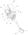
- FIG. 2 is a perspective view showing an embodiment of a 3D oral scanner according to the present invention
- FIG. 2 is an exploded perspective view of FIG. 2,
- FIG. 4 is a cross-sectional view taken along line A-A of FIG. 2,
- FIG. 5 is a perspective view showing an optical path using a pair of stereo cameras in the configuration of FIG. 2,
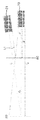
- FIG. 6 is a schematic plan view for explaining the position design of a single polarization filter in the configuration of FIG. 2,
- FIG. 7 is a schematic plan view showing the image angle of view, the projection angle of view, and the triangulation angle of FIG. 6;
- FIG. 8 is a schematic diagram visually showing a fixing part of at least one camera and a light projector, and a fixing part of a single polarizing filter in the configuration of a 3D oral scanner according to an embodiment of the present invention
- FIG. 9 is a schematic diagram showing an ideal installation model of at least one camera and an optical projector in the configuration of FIG. 8,
- FIG. 10 is a schematic diagram illustrating various types of tolerances when installing at least one camera and an optical projector in the configuration of FIG. 8,
- FIG. 11 is a schematic diagram showing the effect of using a single polarization filter
- FIG. 12 is a schematic diagram showing another effect when a single polarization filter is used.
- 31b,32b imaging sensor 41,42: light path changing mirror
- optical projector 80 single polarizing filter
- FIG. 2 is a perspective view showing an embodiment of a 3D oral scanner according to the present invention
- FIG. 3 is an exploded perspective view of FIG. 2
- FIG. 4 is a cross-sectional view taken along line AA of FIG. 2
- FIG. 5 is A perspective view showing an optical path using a pair of stereo cameras in the configuration
- FIG. 6 is a schematic plan view for explaining the position design of a single polarization filter in the configuration of FIG. 2.
- An embodiment of the 3D oral scanner according to the present invention includes a case 10 capable of being inserted and withdrawn into the oral cavity.
- At least one camera 20 may be disposed inside the case 10. That is, at least one camera 20, although not shown in the drawing, is a single camera 20 and may be disposed inside the case 10. In addition, at least one camera 20 may be disposed inside the case 10 as a pair of stereo cameras 20, as shown in FIG. 3.
- the width direction of the case 10 is to pass light incident from one end of the case 10 through different paths. Can be arranged spaced apart.
- at least one camera 90 is disposed inside the case 10, but it should be noted that the application of the single camera 20 is not completely excluded.
- the term'light' means, in a broad sense, light in the visible light range that can be seen by the human eye, but refers to light in the infrared or ultraviolet light that can be observed using a special optical device. It may be a concept that includes all, and in a narrow sense, it may refer to a shape inside the oral cavity of a patient to be measured (hereinafter, abbreviated as'burn').
- the case 10 may be provided with an opening 16 that is opened so that an image is introduced into the interior in the form of light through one end.
- the opening 16 may be an inlet through which light from the outside of the case 10 flows into the interior of the case 10.
- Light incident through the opening 16 is transmitted to each of the pair of stereo cameras 20 while forming different light paths, respectively.
- the light transmitted through the pair of stereo cameras 20 is photographed through imaging sensors 31b and 32b provided in imaging boards 31a and 32a to be described later.
- the pair of stereo cameras 20 may include at least two transmissive lenses capable of adjusting focus on an image in the oral cavity.
- an embodiment of the 3D oral scanner 1 according to the present invention is an imaging board 31a having an imaging sensor 31b and 32b for imaging light transmitted through a pair of stereo cameras 20, respectively. ,32a) may be further included.
- a camera control board mounted with an electric component for controlling the operation of a pair of stereo cameras 20 and an electric field for processing the scanned image A scanning control board on which a component is mounted may be further included.
- the case 10 is a pair of stereo cameras 20, imaging boards 31a and 32a, a camera control board (not shown), and a scanning control board (not shown), as referenced in FIGS. 2 to 4. ) Serves to provide a predetermined space to be embedded.
- the case 10 is provided on the upper side of the lower case 12 and the lower case 12 in which a predetermined space is formed in which the components are embedded, as shown in FIG. 3, the lower case 12 ) Is detachably coupled to the body case 11 made of an upper case 13 covering the above configurations.
- the case 10 is coupled to one end of the main body case 11, the above-described opening 16 is formed, and the light incident into the body case 11 through the opening 16 and the opening 16
- the tip case 14 may further include a tip case 14 in which the input/output path part 17 for guiding the light emitted from the inside of the main body case 11 is formed.
- the inside of the tip case 14 is provided in the form of a darkroom 85 in which incident light and emitted light, which will be described later, are not leaked, and the darkroom 85 is formed to have a different length according to the age group and oral characteristics of the patient to be measured. I can.
- the total length of the tip case 14 is relatively small, and in this case, the length of the darkroom 85 may also be made relatively small.
- the total length of the tip case 14 is relatively large, and the length of the darkroom 85 in this case may also be made relatively large.
- the tip case 14 is coupled to one end of the main body case 11, and a dark room of a different length according to the length measured from one end to the other end so that it can be easily separated and replaced according to the patient to be measured. It is manufactured in various specifications so as to be provided, and may be detachably coupled to one end of the main body case 11.
- a single polarizing filter 80 which will be described later, is installed, and the length of the dark room 85 is within a limit that satisfies the set distance d for setting the position of the single polarizing filter 85, which will be described later. It can be manufactured in various lengths, and at this time, the single polarizing filter 85 may be fixed in a different position satisfying the above setting distance d, so that the tip case 14 of various specifications may be replaced and used.
- the light incident into the body case 11 through the opening 16 refers to an image of the inside of the patient's oral cavity, and the body case through the opening 16 (11)
- Light emitted from the inside refers to irradiation light radiated from the light projector 70 to be described later.
- a light guide structure in which the incident light and the exit light are easily irradiated to the inside and outside of the case 10 may be formed inside the tip case 14.
- the opening 16 is formed to be opened in one direction orthogonal to the longitudinal direction of the tip case 14, and a reflective member 60 to be described later may be disposed in the opening 16.
- the front ends of the pair of stereo cameras 20, as described above, are disposed to converge at the tip case 14 side, and may be disposed to overlap the tip case 14 by a predetermined distance.
- the rear ends of the pair of stereo cameras 20 may be provided to be connected to the camera mounting unit 50 fixed inside the body case 11.
- an embodiment of the 3D oral scanner 1 according to the present invention is disposed inside the case 10, between a pair of stereo cameras 20
- a light projector 70 that emits predetermined emission light through the case 10 and irradiates the emission light through an opening 16 formed at the front end of the tip case 14 of the case 10 may be further included.
- one embodiment of the three-dimensional oral scanner 1 according to the present invention is located between a pair of stereo cameras 20 and the opening 16, a pair
- the stereo camera 20 may further include a single polarization filter 80 positioned at a position spaced apart from the front end by a set distance (d).
- the configurations as described above are arranged inside the case 10, but from the user's side, the 3D oral scanner 1 according to the present invention is easily gripped.
- the slim design of the main body case 11 is related to the arrangement design of the imaging sensors 31b and 32b separately provided for each incident light incident through each of the pair of stereo cameras 20, as described later.
- the slim design of the tip case 14 is related to the arrangement design of the single polarizing filter 80 as described later.
- a camera mounting unit 50 may be disposed to form an optical waveguide that is a path of incident light transmitted through the pair of stereo cameras 20 or emitted light emitted from the light projector 70.
- the optical waveguide formed in the camera mounting unit 50 may be provided in a dark room shape so that incident light incident from the opening 16 and output light irradiated from the light projector 70 are partitioned from each other and do not affect each other.
- the optical waveguide is incident through an emission light path part 53 providing an optical path to the tip case 14 side of the emitted light irradiated from the optical protector, and one of the pair of stereo cameras 20
- One side incident light path unit 51 providing an optical path of the incident light
- the other side incident light path unit 52 providing an optical path of incident light incident through the other side of the pair of stereo cameras 20. I can.
- the exit light path portion 53, the incident light path portion 51 on the one side, and the incident light path portion 52 on the other side are provided so as to be partitioned from each other, so that the light of each path may not affect each other at all.
- the optical protector is located at the center of the other end of the pair of stereo cameras 20 arranged to be spaced apart from each other by a predetermined distance in the width direction of the case 10, and the exit light path part 53 is one side incident light path part. It may be formed between 51 and the other side incident light path portion 52.
- One side incident light path part 51 and the other side incident light path part 52 are formed to match the longitudinal direction of a stereo camera corresponding to each so that the incident light incident from the pair of stereo cameras 20 is transmitted. It may be formed to open to one side and the other side of the mounting part 50.
- the imaging boards 31a and 32a in which the imaging sensors 31b and 32b are integrated may be vertically disposed so as to be in close contact with one side wall in the width direction and the other side wall in the width direction of the case 10.
- the imaging boards 31a and 32a of one side are disposed to be in close contact with one side of the camera mounting unit 50, and may be disposed between one side wall in the width direction of the case 10.
- the imaging boards 31a and 32a on the other side may be disposed between the other side walls in the width direction of the case 10 even if they are arranged to be in close contact with the other side of the camera mounting unit 50.
- the imaging boards 31a and 32a on one side are provided so that the imaging sensors 31b and 32b integrated therein are exposed to the incident light path part 51 on the other side, and the imaging boards 31a and 32a on the other side are integrated therein.
- the imaging sensors 31b and 32b may be provided to be exposed to the other incident light path part 52.
- One of the pair of optical path changing mirrors 41 and 42 transmits the incident light transmitted through the incident light path portion 51 to the imaging sensors 31b and 32b integrated on the imaging boards 31a and 32a on one side.
- One side of the light path changing mirror 41 that changes the path of the incident light to be irradiated, and the other of the pair of light path changing mirrors 41, 42, the other side of the incident light transmitted through the other side incident light path unit 52 It may be the other optical path changing mirror 42 that changes the path of the incident light so as to be irradiated to the imaging sensors 31b and 32b integrated on the imaging boards 31a and 32a of FIG.
- the pair of optical path changing mirrors 41 and 42 herein may include a total reflection mirror capable of total reflection of light. However, it is not necessarily limited to the total reflection mirror, and any optical element capable of total reflection may be included.
- An embodiment of the 3D oral scanner 1 according to the present invention is to secure 3D image data of a patient's oral cavity (ie, an image) using a pair of stereo cameras 20.
- one end of the pair of stereo cameras 20 (referring to the direction in which the tip case 14 is provided in the drawing) includes a reflective member 60 provided in one opening 16, respectively.
- the other end of the pair of stereo cameras 20 (referring to the direction in which the light projector 70 is provided in the drawing) transmits incident light transmitted through each in a linear direction. It must have a structure that transmits it.
- the pair of imaging boards 31a and 32a should be disposed to be spaced apart in the width direction of the case 10 so as to be orthogonal to the straight direction of the other end of each of the pair of stereo cameras 20.
- the thickness of the main body case 11 in the width direction may be increased by the length of the pair of imaging boards 31a and 32a.
- the incident light path portions 51 and 52 are formed to be opened to one side and the other side of the camera mounting unit 50, respectively.
- the mounting positions of the imaging boards 31a and 32a are vertically disposed between one side and the other side of the camera mounting unit 50 and one side wall and the other side wall of the case 10, and a pair of stereo cameras 20
- the body case 11 is slimmed so that the measurer can easily grip and use only with the thumb, forefinger, and middle finger. Can be formed.
- the pair of optical path changing mirrors 41 and 42 are each of the imaging sensors 31b and 32b in which incident light transmitted through the pair of stereo cameras 20 is provided on the pair of imaging boards 31a and 32a. It may be disposed to have a reflector surface of an angle incident on one surface of the.
- the pair of optical path changing mirrors 41 and 42 may have a reflector surface inclined with respect to the longitudinal direction of the case 10. That is, the light path changing mirror 41 on one side is refracted by the reflector surface of the light path changing mirror 41 after the incident light transmitted through the stereo camera 21 is incident through the incident light path unit 51 on the one side. As a result, it may be provided to irradiate the imaging sensors 31b and 32b of one side of the imaging board 31a.
- the other optical path changing mirror 42 is refracted by the reflector surface of the other optical path changing mirror 42 after incident light transmitted through the other stereo camera 22 is incident through the other incident light path part 52 It can be provided to be irradiated to the imaging sensors (31b, 32b) of the other side of the imaging board (31b).
- FIG. 6 is a schematic plan view for explaining the position design of a single polarization filter in the configuration of FIG. 2
- FIG. 7 is a schematic plan view showing the image field of view 92a and 92b, the projection angle of view 91, and the triangulation angle of FIG. .
- a pair of stereo cameras 20 on the front end side of the main body case 11 is a tip case 14
- the light projector 70 may be provided so as to overlap a predetermined length toward the provided side, and to emit light through a pair of stereo cameras 20.
- a single polarizing filter 80 is provided to remove the internal reflection light of the measurement object 100 made of an internal reflection material such as teeth and filter only the surface reflection light to pass through. Can be.
- the single polarization filter 80 may be installed to be positioned in the tip case 14 of the case 10.
- an upper installation rib (not shown) and a lower installation rib 81 may be integrally formed. That is, the single polarization filter 80 may be installed by fitting the upper and lower ends to the upper and lower ribs 81 integrally formed in the tip case 14.
- the single polarization filter 80 is located inside the tip case 14 corresponding between the pair of stereo cameras 20 and the opening 16, and a set distance (d) from the front end of the pair of stereo cameras 20 ) Can be located in a spaced position.
- the single polarization filter 80 is a projection angle of view 91 that the light emitted by the light projector 70 projects and the light reflected from the measurement object 100, as shown in FIG. 6. It is preferable that the set distance (d) is set to a distance in which the two image viewing angles 92a and 92b respectively incident on the pair of stereo cameras 20 do not overlap each other.
- the light emitted from the optical projector 70 passes through the single polarizing filter 80 and then passes through the opening 16 to the inside of the patient's oral cavity where the measurement object 100 is positioned, as shown in FIG. 6. It is projected, and the maximum area through which the light emitted from the light projector 70 passes through the single polarization filter 80 may be defined as the projection angle of view 91 as described above.
- the light emitted from the light projector 70 and projected into the oral cavity of the patient is reflected from the object to be measured 100, and then flows into the tip case 14 through the opening 16 again. It is incident to each of a pair of stereo cameras 20 spaced apart in the width direction of the case 11, where the maximum area transmitted through the single polarization filter 80 when incident to each of the pair of stereo cameras 20 As described above, can be defined as the image field of view 92a and 92b.
- the position where the single polarization filter 80 is installed is set to a position where the projection angle of view 91 and the image view angles 92a and 92b overlap each other, the light projected from the light projector 70 is transmitted to the single polarization filter 80 ) May be reflected by itself from the transmission surface and incident on the pair of stereo cameras 20.
- the image acquired through the imaging sensors 31b and 32b may generate a so-called ghost image or noise in which a spot brighter than the surrounding image is generated.
- the image viewing angles 92a and 92b may be designed to set the set distance d at a position where they do not overlap each other.
- the set distance (d) defining the position of the single polarizing filter 80 is a pair of reflected light reflected by the single polarizing filter 80 from the light projected into the oral cavity from the optical projector 70 It may be set not to be incident to each of the stereo cameras.
- the set distance (d) is sufficient if the projection angle of view 91 and the image angles of view 92a and 92b are set to position the single polarization filter 80 in a range where they do not overlap each other, so a single polarization filter ( 80) may be positioned as close as possible to the front end of the pair of stereo cameras 20.
- a single polarization filter ( 80) may be positioned as close as possible to the front end of the pair of stereo cameras 20.
- the size of the single polarization filter 80 when a single camera is applied, at least the size of the single polarization filter 80 is physically the above-described projection angle of view 91 and the image angle of view (any of 92a and 92b of FIG. 6).
- One reference is required to be larger than the size of the single camera, and when the single polarization filter 80 is designed to be positioned as close as possible to the front end of the single camera, an increase in the width direction is inevitably expected.
- a pair of stereo cameras 20 are used in the main body case. It is installed in the width direction of (11), but the front end of the pair of stereo cameras 20 is set to overlap with the tip case 14.
- the single polarization filter 80 should be manufactured at least in a size capable of implementing the image field of view (92a, 92b). As described above, the single polarization filter 80 is as much as possible toward the pair of stereo cameras 20. In the case of the close design, the size in the width direction must be increased inevitably, and thus a problem of hindering the slim design of the tip case 14 occurs.
- the set distance (d) of the single polarizing filter 80, the single polarizing filter 80 is a pair Assuming that the upper and lower widths and the left and right widths (hereinafter, abbreviated as'full size') of the single polarizing filter 80 increase as they approach toward the stereo camera 20, the total size of the single polarizing filter 80 Can be set in the smallest position.
- the single polarization filter 80 even if the single polarization filter 80 is approached to a pair of stereo cameras 20 to have a minimum separation distance, the single polarization filter 80 It should be set to a location where there is no mechanical or structural interference between the and surrounding components.
- the optimal setting distance d of the single polarization filter 80 may be set to satisfy the following equation, as shown in FIG. 7.
- d is the set distance
- D is the aperture of one camera lens
- the single polarization filter 80 can be positioned close to a minimum distance as long as there is no mechanical interference with the pair of stereo cameras 20. You will be able to.
- the single polarization filter 80 is close to the pair of stereo cameras 20, there is a problem that the overall size increases, so even in this case, the effect of slim manufacturing in an embodiment of the present invention. It should be designed in consideration of
- D is the aperture of the camera lens 21 on one side, and the increase in D means that the set distance d should be designed to be smaller, and becomes an impediment to the slim design. Therefore, it is desirable to design D to the minimum as possible, and the optical projector 70 and the pair of stereo cameras 21 and 22 each have to prioritize an optimal structural design in which the instrument interference does not occur.
- the direct reflected light L1 is transmitted through the single polarizing filter 80 forming the projection angle of view 91 to the camera 21 It must satisfy the condition not to penetrate into
- an increase in the aperture D of the camera lens 21 leads to an increase in the image field of view 92b, and in this case, the projection angle of view 91 and the image field of view 92b may overlap each other, and the set distance ( d) should be designed to be smaller.
- Equation 1 described above presents a theoretical background for deriving an optimal set distance d of a single polarization filter 80 capable of implementing all of these purposes.
- the reflective member 60 may be provided in the opening 16 formed in the tip case 14 as described above.
- the reflective member 60 serves to reflect incident light incident into the body case 11 and outgoing light emitted from the body case 11 through a predetermined path.
- the reflective member 60 may be provided in the form of a mirror or a prism.
- the reflective member 60 facilitates photographing through a pair of stereo cameras 20 through an opening 16 formed to be opened in one direction orthogonal to the longitudinal direction of the case 10.
- the single polarization filter 80 may be disposed between the pair of stereo cameras 20 and the reflective member 60, and may be disposed parallel to the light projector 70.
- the meaning that the single polarization filter 80 is disposed in parallel with the optical projector 70 means that each polarization filter is provided for each exit path of the exit light from the conventional optical projector 70 and the incident path of the incident light to the camera lens, This means that it has the advantage of eliminating the complicated process of designing the position of each polarization filter very precisely to reduce polarization efficiency.
- the measurer presses the operation button 15 provided on the upper part of the case 10 in order to measure into the patient's oral cavity using an embodiment of the 3D oral scanner 1 according to the present invention.
- the light emitted from the light projector 70 is irradiated.
- the outgoing light irradiated from the optical projector 70 is sequentially passed through the outgoing light path part 53 of the optical waveguides formed in the camera mounting part 50 and the in/out light path part 17 formed in the tip case 14 It is irradiated toward the opening 16 and is irradiated into the oral cavity of the patient through the opening 16 by the reflective member 60.
- the pair of stereo cameras 20 are operated by the operator pressing the operation button 15, so that two images having the same focus at any one point of the image You can get the data.
- the oral image of the patient exists in the form of light by the emitted light, and contrary to the emitted light, it is sequentially incident into the tip case 14 through the opening 16, and the path through the reflective member 60 Is changed, and a corresponding incident light path part 51 among the above-described input/output light path part 17, a corresponding stereo camera, and an optical waveguide with a pair of camera lenses that substantially photograph the reflective surface of the reflective member 60 52).
- two predetermined image data can be simultaneously secured. Based on the two image data secured in this way, 3D data on the oral image of the patient can be easily secured.
- FIG. 8 is a schematic diagram showing visually a fixing part of at least one camera and a light projector and a fixing part of a single polarizing filter among the configurations of a 3D oral scanner according to an embodiment of the present invention
- FIG. 9 is It is a schematic diagram showing an ideal installation model of at least one camera and an optical projector
- FIG. 10 is a various schematic diagram illustrating the occurrence of tolerances when installing at least one camera and an optical projector among the configurations of FIG. 8, and
- FIG. 11 is a single polarization
- FIG. 12 is a schematic diagram showing another effect of using a single polarization filter.
- FIG. 8 to 12 are schematic diagrams for explaining an effective aspect of a 3D oral scanner according to an embodiment of the present invention, and as shown in FIG. 8, a stereo camera provided inside the body case 14 ( 21) and the other side stereo camera 22, the optical projector 70 therebetween, and the single polarization filter 80, respectively, the lower end of each of the preset fixed position (reference numerals 21a, 21b, 22a, 22b, 70a in Fig. 8, 70b, and 80a, 80b) are most preferred to be installed without tolerances.
- the projection angle of view 91 and the object to be measured 100 are projected by the light emitted by the light projector 70.
- an assembly tolerance occurs in the other stereo camera 22, as referenced in FIG. 10(a), or as referenced in FIG. 10(b), one stereo camera 21
- An assembly tolerance may occur in, and as shown in FIG. 10(c), an assembly tolerance may occur only in the optical projector 70, and as shown in FIG. 10(d), one stereo camera 21 )
- the other side stereo camera 22 may have an assembly tolerance.
- the single polarization filter 80 as in the embodiment of the present invention is not applied and polarization filters are applied for each, the precision of the measured value is lowered due to the assembly tolerance of the above three configurations. Will occur.
- the measurement object is measured by mechanical tolerances with polarization filters corresponding to both stereo cameras 21 and the other stereo camera 22.
- the reflected light through is bound to be (100-@)%.
- the projection angle of view of the light projector 70 and the projection angle of view are similar to the shaded portions respectively displayed on the image field of view and the projection angle of view. Since the angles of the image field of view are all the same, it can be seen that the efficiency of the projected light and the reflected light is also the same.
- the projection angle of view of the optical projector 70 and the image angle of view by the one stereo camera 21 and the other stereo camera 22 are sized according to the above equation, and the area of the single polarization filter 80 is Because it does not deviate, it has the advantage of greatly improving the reliability.
- the present invention provides a 3D oral scanner capable of manufacturing a slim body case so that it is possible to secure 3D image data at the same time as measuring an object to be measured, as well as to facilitate gripping by a user.
Abstract
The present invention relates to a three-dimensional intraoral scanner specifically comprising: a case which can be inserted into and withdrawn from the oral cavity, and has an opening portion which is open to allow the form of the inside of the oral cavity (hereinafter, referred to as an 'image') to be incident into the case in the form of light via an end portion thereof; at least one camera which is arranged inside the case to transmit the light incident via the opening portion of the case; a light projector which is arranged on one side of the at least one camera and emits light into the oral cavity via the opening portion; and a single polarized filter which is positioned between the at least one camera and the opening portion at a position spaced a set distance (d) from the front end of the at least one camera. Thus, the present invention provides the advantages of making it possible to manufacture a product having a slim size and improve the reliability with which an object to be measured can be measured.
Description
본 발명은 3차원 구강 스캐너(3-DIMENSIONAL INTRAORAL SCANNER)에 관한 것으로서, 보다 상세하게는, 적어도 하나의 카메라를 통해 측정 대상물을 용이하게 측정할 수 있는 3차원 구강 스캐너에 관한 것이다.The present invention relates to a three-dimensional oral scanner (3-DIMENSIONAL INTRAORAL SCANNER), and more particularly, to a three-dimensional oral scanner that can easily measure a measurement object through at least one camera.
일반적으로, 구강 스캐너는 치과 환자의 구강 내에 삽입되어 비접촉식으로 치아를 스캐닝함으로써 치열에 대한 3차원 스캐닝 모델을 생성하기 위한 광학장치이다.In general, an oral scanner is an optical device for generating a three-dimensional scanning model of a dental row by being inserted into the oral cavity of a dental patient and scanning teeth in a non-contact manner.
단일 카메라를 이용하여 다중 시점(view)에서 측정한 영상을 이용하여 3차원 정보를 획득하는 종래 기술로는, 서로 다른 시점의 영상의 좌표계를 이용하여 물체와 카메라간의 거리 정보를 구하는 방법으로 연속으로 촬영된 영상 정보를 정합하여 각 영상에서 서로 일치하는 물체를 찾은 후 사형식(projection)을 이용하여 물체의 거리 정보를 추출한다. 따라서, 3차원 정보를 처리하는데 어려움이 존재하고 계산량이 많아지는 문제가 있으며, 최근에는 두 개 이상의 카메라에서 얻어진 이미지를 이용하는 스테레오 비전(stereo vision) 방식이 구강 스캐너에 적용되고 있다.As a conventional technique for acquiring 3D information using images measured at multiple views using a single camera, a method of obtaining distance information between an object and a camera using a coordinate system of images at different viewpoints. After matching the photographed image information to find an object that matches each other in each image, distance information of the object is extracted using a projection. Accordingly, there is a problem in that processing 3D information is difficult and the amount of calculation is increased, and recently, a stereo vision method using images obtained from two or more cameras has been applied to an oral scanner.
하지만, 스테레오 비전 방식을 이용한 3차원 데이터 측정의 경우, 최소한 두 대 이상의 카메라가 필요하고, 두 대의 카메라는 동일한 방향으로 측정대상을 바라보아야 하므로 두 대의 카메라를 수용하기 위한 구강 스캐너 내부 공간의 활용에 제약이 생기는 문제가 있고, 제품 전체의 크기가 증대하게 되어 기구 설계 제작이 어려운 문제가 있다.However, in the case of 3D data measurement using the stereo vision method, at least two cameras are required, and since the two cameras must look at the measurement target in the same direction, it is not necessary to use the space inside the oral scanner to accommodate the two cameras. There is a problem in that there is a limitation, and the size of the entire product increases, making it difficult to design and manufacture a device.
도 1은 구강 스캐너를 이용한 3차원 정보 획득 모식도 및 편광판 적용 모식도이다.1 is a schematic diagram of obtaining 3D information using an oral scanner and a schematic diagram of applying a polarizing plate.
일반적으로 구강 스캐너를 이용하여 구강 내의 치아에 관한 3차원 스캐닝 모델을 형성하기 위해서는, 도 1의 (a)에 도시된 바와 같이, 측정 대상물(O)인 치아에 구조광을 투영하고 그로부터 반사된 빛을 획득하여 이로부터 3차원 데이터를 획득하는 방식을 취한다.In general, in order to form a three-dimensional scanning model of a tooth in the oral cavity using an oral scanner, as shown in Fig. 1(a), structured light is projected onto the tooth, which is the measurement object O, and the light reflected therefrom. Takes a method of obtaining 3D data from it.
즉, 광 발생부(170)로부터 발생된 광(光)은 프로젝션 렌즈(171)를 투과하여 측정 대상물(O)인 치아를 포함한 구강 내부에서 반사된 후 카메라 렌즈(121)를 통하여 내부로 입사되어 이미징 센서(130)를 통하여 3차원 데이터가 획득된다.That is, the light generated from the light generating unit 170 passes through the projection lens 171 and is reflected from the inside of the oral cavity including the tooth that is the measurement object O, and then enters the inside through the camera lens 121. 3D data is obtained through the imaging sensor 130.
이러한 방식으로 치아에 관한 정밀한 표면 데이터를 획득하기 위해서는 투영된 구조광이 측정 대상물(O)의 표면인 치아에 정확히 투사되고 이를 획득하는 것이 중요하다. 그러나, 석고 모델과 같이 투사된 빛이 표면에서 반사되는 표면 반사(Surface reflection) 재질이 아닌 치아와 같은 내부 반사(Inner reflection) 재질인 경우 물체의 투영된 빛이 측정 대상물의 표면 뿐만 아니라 재질 내부로 투과되어 반사되는 영향으로 정확한 3차원 데이터를 획득할 수 없는 기술적인 문제가 있었다.In order to obtain precise surface data on a tooth in this way, it is important that the projected structured light is accurately projected onto the tooth, which is the surface of the object O, and obtained. However, if the projected light is not a surface reflection material such as a gypsum model, but an inner reflection material such as a tooth, the projected light of the object is transferred not only to the surface of the object to be measured, but also to the inside of the material. There was a technical problem in that accurate 3D data could not be obtained due to the transmitted and reflected effect.
이를 해결하기 위하여, 광학적 파동 특성을 활용하여 측정 대상물의 내부 반사 재질의 표면에서만 반사된 빛을 획득하는 방법들(예를 들면 편광판을 이용하는 방법)이 연구 및 개발되고 있는 실정이나, 편광판을 이용하는 경우에도 3차원 데이터의 손실이 없도록 정밀한 축(axis) 조절 및 편광판 자체의 표면 반사 문제로 인한 적용에 어려움이 있는 실정이다.In order to solve this problem, methods of acquiring light reflected only on the surface of the internal reflective material of the object to be measured using optical wave characteristics (for example, a method using a polarizing plate) are being researched and developed, but when a polarizing plate is used Even in this situation, it is difficult to apply it due to the problem of precise axis control and surface reflection of the polarizer itself so that there is no loss of 3D data.
아울러, 편광판을 적용하는 경우에도 도 1의 (b)에 도시된 바와 같이, 광 발생부(170)로부터 광이 측정 대상물(O)에 투사되기 전의 투사 경로에 제1편광판(180a)을 구비하고, 측정 대상물(O)로부터 반사되어 카메라 렌즈(121)로 입사되기 전의 입사 경로에 제2편광판(180b)을 구비하여야 하는데, 이는 단일 카메라의 경우 적어도 2개의 편광판(180a,180b)을 구비하여야 함을 의미하고, 나아가 스테레오 비전 방식이 적용된 경우에는 적어도 3개의 편광판을 구비하여야 함을 의미하는 바, 전체적인 제품의 슬림 설계가 매우 난망한 문제점으로 이어진다.In addition, even when a polarizing plate is applied, as shown in FIG. 1(b), the first polarizing plate 180a is provided in the projection path before the light is projected from the light generating unit 170 to the measurement object O, , A second polarizing plate 180b should be provided in the incident path before being reflected from the measurement object O and incident on the camera lens 121, which should be provided with at least two polarizing plates 180a, 180b in the case of a single camera. In addition, when the stereo vision method is applied, it means that at least three polarizing plates must be provided, and the overall slim design of the product leads to a very difficult problem.
본 발명의 목적은, 측정 대상물의 측정과 동시에 3차원 이미지 데이터의 확보가 가능함은 물론, 사용자의 파지가 용이하도록 본체 케이스의 슬림 제조가 가능한 3차원 구강 스캐너를 제공하는 것이다.It is an object of the present invention to provide a 3D oral scanner capable of manufacturing a slim body case so that it is possible to secure 3D image data at the same time as the measurement of an object to be measured, as well as to facilitate gripping by a user.
또한, 본 발명의 다른 목적은, 측정 대상물을 측정함에 있어서 치아와 같은 내부 반사 물질에 의한 내부 반사 광을 제거하여 보다 선명하고 정밀한 측정이 가능하도록 하는 3차원 구강 스캐너를 제공하는 것이다.In addition, another object of the present invention is to provide a 3D oral scanner capable of clearer and more precise measurement by removing internal reflection light by an internal reflective material such as a tooth in measuring a measurement object.
아울러, 본 발명의 다른 목적은, 환자의 구강 내부로 인입 가능하게 구비된 팁 케이스의 슬림 제조가 가능하면서 고스트 이미지 또는 노이즈가 발생하지 않는 최적의 설계안을 제공할 수 있는 3차원 구강 스캐너를 제공하는 것이다.In addition, another object of the present invention is to provide a 3D oral scanner capable of providing an optimal design that does not generate ghost images or noise while enabling slim manufacturing of a tip case provided to be retractable into the oral cavity of a patient. will be.
본 발명의 기술적 과제들은 이상에서 언급한 과제들로 제한되지 않으며, 언급되지 않은 또 다른 기술적 과제들은 아래의 기재들로부터 당업자에게 명확하게 이해될 수 있을 것이다.The technical problems of the present invention are not limited to the above-mentioned problems, and other technical problems that are not mentioned will be clearly understood by those skilled in the art from the following description.
상기의 목적을 달성하기 위한 본 발명의 일 실시예에 따른 3차원 구강 스캐너는, 구강 내에 인입 및 인출이 가능하고, 일단부를 통해 상기 구강 내부의 모습(이하, '화상'이라 약칭함)이 광의 형태로 내부로 입사되도록 개구된 개구부가 형성된 케이스, 상기 케이스의 내부에 배치되고, 상기 케이스의 개구부를 통하여 입사된 광을 통과시키도록 배치된 적어도 하나의 카메라, 상기 적어도 하나의 카메라 사이에 배치되어 상기 개구부를 통해 상기 구강 내부로 광을 조사하는 광 프로젝터 및 상기 적어도 하나의 카메라와 상기 개구부 사이에 위치되되, 상기 적어도 하나의 카메라 전단으로부터 설정거리(d)만큼 이격된 위치에 위치된 단일 편광 필터를 포함한다.The three-dimensional oral scanner according to an embodiment of the present invention for achieving the above object is capable of being inserted and withdrawn into the oral cavity, and the appearance of the inside of the oral cavity (hereinafter, abbreviated as'image') through one end is broadly A case in which an opening is formed so as to enter the case in a form, at least one camera disposed inside the case and disposed to pass light incident through the opening of the case, and disposed between the at least one camera A light projector that irradiates light into the oral cavity through the opening, and a single polarization filter positioned between the at least one camera and the opening, but spaced apart by a set distance (d) from the front end of the at least one camera Includes.
여기서, 상기 설정거리(d)는, 상기 광 프로젝터로부터 상기 구강 내부로 투사되는 투사 화각과, 상기 구강 내부로부터 반사되어 상기 적어도 하나의 카메라로 입사되는 이미지 화각이 상호 겹치지 않는 거리로 설정될 수 있다.Here, the set distance (d) may be set to a distance in which a projection angle of view projected from the light projector into the oral cavity and an image angle of view reflected from the oral cavity and incident to the at least one camera do not overlap each other. .
또한, 상기 설정거리(d)는, 상기 광 프로젝터로부터 상기 구강 내부로 투사되는 광이 상기 단일 편광 필터에 의하여 반사된 반사 광 형태로 상기 적어도 하나의 카메라로 입사되지 않도록 설정될 수 있다.In addition, the set distance (d) may be set so that light projected from the optical projector into the oral cavity is not incident to the at least one camera in the form of reflected light reflected by the single polarizing filter.
또한, 상기 설정거리(d)는, 상기 단일 편광 필터가 상기 적어도 하나의 카메라를 향하여 접근할수록 상기 단일 편광 필터의 상하 폭 및 좌우 폭(이하, '전체 크기'라고 약칭함)이 증가한다고 전제할 때, 상기 단일 편광 필터의 전체 크기가 가장 작은 위치에 설정될 수 있다.In addition, the set distance (d) is assumed that the upper and lower widths and the left and right widths (hereinafter, abbreviated as'full size') of the single polarizing filter increase as the single polarizing filter approaches the at least one camera. In this case, the total size of the single polarization filter may be set at the smallest position.
또한, 상기 설정거리(d)는, 다음의 수학식을 만족할 수 있다.In addition, the set distance (d) may satisfy the following equation.
즉, 수학식 :  이고, 여기서, d는 상기 설정거리이고,
  는 광 프로젝터로부터 화상까지의 거리이며,
  는 일측 카메라 렌즈로부터 화상까지의 거리이고,
  는 삼각측량 각도이며, D는 일측 카메라 렌즈의 구경이고,
  는 투사 화각이다.That is, the equation: And, where d is the set distance, Is the distance from the light projector to the image, Is the distance from one camera lens to the image, Is the triangulation angle, D is the aperture of one camera lens, Is the projection angle of view.
또한, 상기 케이스는, 상기 적어도 하나의 카메라 및 이를 구동시키기 위한 각종 전장 부품이 내장되는 본체 케이스 및 상기 본체 케이스의 일단부에 결합되고, 상기 개구부가 형성된 팁 케이스를 포함하고, 상기 단일 편광 필터는, 상기 설정거리(d)가 상기 팁 케이스에 위치되도록 설치될 수 있다.In addition, the case includes a body case in which the at least one camera and various electric components for driving the same are embedded, and a tip case coupled to one end of the body case and having the opening, wherein the single polarization filter , It may be installed so that the set distance (d) is located in the tip case.
또한, 상기 팁 케이스의 내부에는 상기 단일 편광 필터의 상단 및 하단이 삽입되어 설치되는 상단 설치 리브 및 하단 설치 리브가 일체로 형성될 수 있다.In addition, an upper rib and a lower rib may be integrally formed in the tip case in which the upper and lower ends of the single polarizing filter are inserted and installed.
또한, 상기 팁 케이스는, 상기 설정거리(d)가 위치되되, 일단부로부터 타단부까지 측정되는 길이에 따라 상이한 길이의 암실을 구비하도록 다양한 제원으로 제조되고, 상기 본체 케이스의 일단부에 대한 분리 교체가 용이하도록 상기 본체 케이스의 일단부에 착탈 가능하게 결합될 수 있다.In addition, the tip case is manufactured with various specifications so as to have a darkroom having a different length according to the length measured from one end to the other end, where the set distance (d) is located, and is separated from one end of the main body case It may be detachably coupled to one end of the main body case to facilitate replacement.
또한, 상기 팁 케이스는, 상기 암실의 길이에 따라 상기 설정거리(d)를 만족하는 상이한 위치에 상기 단일 편광 필터가 기 고정될 수 있다.In addition, in the tip case, the single polarization filter may be previously fixed at different locations satisfying the set distance d according to the length of the dark room.
본 발명에 따른 3차원 구강 스캐너의 다른 실시예는, 구강 내에 인입 및 인출이 가능하고, 일단부를 통해 상기 구강 내부의 모습(이하, '화상'이라 약칭함)이 광의 형태로 내부로 입사되도록 개구된 개구부가 형성된 케이스, 상기 케이스의 내부에 배치되고, 상기 케이스의 개구부를 통하여 입사된 광을 통과시키도록 배치된 적어도 하나의 카메라, 상기 적어도 하나의 카메라의 일측에 배치되어 상기 개구부를 통해 상기 구강 내부로 광을 조사하는 광 프로젝터 및 상기 적어도 하나의 카메라와 상기 개구부 사이에 위치되되, 상기 광 프로젝터로부터 상기 구강 내부로 투사되는 투사 화각과, 상기 구강 내부로부터 반사되어 적어도 하나의 카메라로 입사되는 이미지 화각이 상호 겹쳐지지 않도록 수평 배치되는 단일 편광 필터를 포함한다.In another embodiment of the 3D oral scanner according to the present invention, it is possible to insert and withdraw into the oral cavity, and an opening so that the shape of the inside of the oral cavity (hereinafter, abbreviated as'image') is incident in the form of light through one end. A case having an opening formed therein, at least one camera disposed inside the case and disposed to pass light incident through the opening of the case, and disposed at one side of the at least one camera and the oral cavity through the opening An optical projector that irradiates light into the interior and a projection angle of view that is positioned between the at least one camera and the opening, and is projected from the optical projector into the oral cavity, and an image reflected from the oral cavity and incident to at least one camera It includes a single polarization filter arranged horizontally so that the angle of view does not overlap each other.
본 발명에 따른 3차원 구강 스캐너의 또 다른 실시예는, 구강 내에 인입 및 인출이 가능하고, 본체 내부로 입사되는 입사광 및 본체 내부로부터 출사되는 출사광을 반사시키는 반사 부재가 구비된 케이스, 상기 케이스의 내부에 배치되고, 상기 케이스의 반사 부재를 통하여 입사된 입사광을 각각 상이한 경로로 통과시키도록 배치된 한 쌍의 스테레오 카메라, 상기 한 쌍의 스테레오 카메라 사이에 배치되어 상기 반사 부재를 통해 상기 구강 내부로 상기 출사광을 조사하는 광 프로젝터 및 상기 한 쌍의 스테레오 카메라와 상기 반사 부재 사이에 위치되되, 상기 광 프로젝터와 평행되게 배치되는 단일 편광 필터를 포함한다.Another embodiment of the 3D oral scanner according to the present invention is a case provided with a reflective member that can be inserted into and withdrawn into the oral cavity and reflects incident light incident into the body and exit light emitted from the body, the case A pair of stereo cameras disposed inside of the case and disposed to pass incident light incident through the reflective member of the case in different paths, respectively, and disposed between the pair of stereo cameras and inside the oral cavity through the reflective member And a single polarization filter positioned between the pair of stereo cameras and the reflective member, and disposed in parallel with the light projector, and an optical projector that irradiates the outgoing light.
본 발명의 일 실시예에 다른 3차원 구강 스캐너에 따르면 다음과 같은 다양한 효과를 달성할 수 있다.According to the 3D oral scanner according to an embodiment of the present invention, various effects as follows can be achieved.
첫째, 이미징 센서가 부착된 이미징 보드를 본체 케이스의 내측벽에 결합시키되, 입사 광을 굴절 또는 변경시키도록 구비함으로써 사용자의 파지가 용이한 본체 케이스의 슬림 제조가 가능한 효과를 가진다.First, the imaging board to which the imaging sensor is attached is coupled to the inner wall of the main body case, and is provided to refract or change the incident light, thereby enabling a slim manufacturing of the main body case to be easily gripped by the user.
둘째, 단일 편광 필터를 통하여 측정 대상물로부터 발생되는 이미지 데이터의 손실없이 정확한 스캔이 이루어지도록 함으로써 제품의 신뢰성을 향상시킬 수 있는 효과를 가진다.Second, it has the effect of improving the reliability of the product by allowing accurate scanning without loss of image data generated from the object to be measured through a single polarization filter.
셋째, 단일 편광 필터의 최적의 위치 설계안을 제시함으로써, 환자의 구강 내부로 유입되는 팁 케이스의 슬림 설계가 가능한 효과를 가진다.Third, by presenting an optimal position design plan of a single polarizing filter, a slim design of the tip case flowing into the patient's oral cavity has an effect.
도 1은 구강 스캐너를 이용한 3차원 정보 획득 모식도 및 편광판 적용 모식도이고,1 is a schematic diagram of obtaining 3D information using an oral scanner and a schematic diagram of applying a polarizing plate,
도 2는 본 발명에 따른 3차원 구강 스캐너의 일 실시예를 나타낸 사시도이며,2 is a perspective view showing an embodiment of a 3D oral scanner according to the present invention,
도 3은 도 2의 분해 사시도이고,3 is an exploded perspective view of FIG. 2,
도 4는 도 2의 A-A선을 따라 취한 단면도이며,4 is a cross-sectional view taken along line A-A of FIG. 2,
도 5는 도 2의 구성 중 한 쌍의 스테레오 카메라를 이용한 광 경로를 나타낸 사시도이고,5 is a perspective view showing an optical path using a pair of stereo cameras in the configuration of FIG. 2,
도 6은 도 2의 구성 중 단일 편광 필터의 위치 설계를 설명하기 위한 평면 모식도이며,6 is a schematic plan view for explaining the position design of a single polarization filter in the configuration of FIG. 2,
도 7은 도 6의 이미지 화각, 투사 화각 및 삼각측량 각도를 나타낸 평면 모식도이고,7 is a schematic plan view showing the image angle of view, the projection angle of view, and the triangulation angle of FIG. 6;
도 8은 본 발명의 일 실시예에 따른 3차원 구강 스캐너의 구성 중 적어도 하나의 카메라 및 광 프로젝터의 고정부 및 단일 편광 필터의 고정부를 가시적으로 나타낸 모식도이며,FIG. 8 is a schematic diagram visually showing a fixing part of at least one camera and a light projector, and a fixing part of a single polarizing filter in the configuration of a 3D oral scanner according to an embodiment of the present invention,
도 9는 도 8의 구성 중 적어도 하나의 카메라 및 광 프로젝터의 이상적인 설치 모델을 나타낸 모식도이고,9 is a schematic diagram showing an ideal installation model of at least one camera and an optical projector in the configuration of FIG. 8,
도 10은 도 8의 구성 중 적어도 하나의 카메라 및 광 프로젝터의 설치 시의 공차 발생 모습을 예시하는 다양한 모식도이며,FIG. 10 is a schematic diagram illustrating various types of tolerances when installing at least one camera and an optical projector in the configuration of FIG. 8,
도 11은 단일 편광 필터를 이용한 경우의 효과를 나타낸 모식도이고,11 is a schematic diagram showing the effect of using a single polarization filter,
도 12는 단일 편광 필터를 이용한 경우의 다른 효과를 나타낸 모식도이다.12 is a schematic diagram showing another effect when a single polarization filter is used.
<부호의 설명> <Explanation of code>
1: 3차원 구강 스캐너 10: 케이스1: 3D oral scanner 10: Case
11: 본체 케이스 12: 로워 케이스11: main body case 12: lower case
13: 어퍼 케이스 14: 팁 케이스13: upper case 14: tip case
16: 개구부 17: 입출광 경로부16: opening 17: input and output light path portion
20: 한 쌍의 스테레오 카메라 21: 일측 스테레오 카메라20: a pair of stereo cameras 21: one side stereo camera
22: 타측 스테레오 카메라 31a,32a: 이미징 보드22: other stereo camera 31a,32a: imaging board
31b,32b: 이미징 센서 41,42: 광경로 변경 미러31b,32b: imaging sensor 41,42: light path changing mirror
50: 카메라 마운팅부 51,52: 입사광 경로부50: camera mounting portion 51, 52: incident light path portion
53: 출사광 경로부 60: 반사 부재53: exit light path part 60: reflective member
70: 광 프로젝터 80: 단일 편광 필터70: optical projector 80: single polarizing filter
81: 하단 설치 리브 91: 투사 화각81: bottom mounting rib 91: projection angle of view
92a,92b: 이미지 화각 100: 측정 대상물92a, 92b: image field of view 100: object to be measured
이하, 본 발명의 일부 실시예들을 예시적인 도면을 통해 상세하게 설명한다. 각 도면의 구성요소들에 참조부호를 부가함에 있어서, 동일한 구성요소들에 대해서는 비록 다른 도면상에 표시되더라도 가능한 한 동일한 부호를 가지도록 하고 있음에 유의해야 한다. 또한, 본 발명의 실시예를 설명함에 있어, 관련된 공지 구성 또는 기능에 대한 구체적인 설명이 본 발명의 실시예에 대한 이해를 방해한다고 판단되는 경우에는 그 상세한 설명은 생략한다.Hereinafter, some embodiments of the present invention will be described in detail through exemplary drawings. In adding reference numerals to elements of each drawing, it should be noted that the same elements are assigned the same numerals as possible even if they are indicated on different drawings. In addition, in describing an embodiment of the present invention, if it is determined that a detailed description of a related known configuration or function obstructs an understanding of the embodiment of the present invention, a detailed description thereof will be omitted.
본 발명의 실시예의 구성요소를 설명하는 데 있어서, 제1, 제2, A, B, (a), (b) 등의 용어를 사용할 수 있다. 이러한 용어는 그 구성요소를 다른 구성요소와 구별하기 위한 것일 뿐, 그 용어에 의해 해당 구성 요소의 본질이나 차례 또는 순서 등이 한정되지 않는다. 또한, 다르게 정의되지 않는 한, 기술적이거나 과학적인 용어를 포함해서 여기서 사용되는 모든 용어들은 본 발명이 속하는 기술분야에서 통상의 지식을 가진 자에 의해 일반적으로 이해되는 것과 동일한 의미를 가진다. 일반적으로 사용되는 사전에 정의되어 있는 것과 같은 용어들은 관련 기술의 문맥상 가지는 의미와 일치하는 의미를 가진 것으로 해석되어야 하며, 본 출원에서 명백하게 정의하지 않는 한, 이상적이거나 과도하게 형식적인 의미로 해석되지 않는다.In describing the constituent elements of the embodiments of the present invention, terms such as first, second, A, B, (a), (b) may be used. These terms are only for distinguishing the component from other components, and the nature, order, or order of the component is not limited by the term. In addition, unless otherwise defined, all terms used herein, including technical or scientific terms, have the same meaning as commonly understood by one of ordinary skill in the art to which the present invention belongs. Terms such as those defined in a commonly used dictionary should be interpreted as having a meaning consistent with the meaning in the context of the related technology, and should not be interpreted as an ideal or excessively formal meaning unless explicitly defined in this application. Does not.
도 2는 본 발명에 따른 3차원 구강 스캐너의 일 실시예를 나타낸 사시도이고, 도 3은 도 2의 분해 사시도이며, 도 4는 도 2의 A-A선을 따라 취한 단면도이고, 도 5는 도 2의 구성 중 한 쌍의 스테레오 카메라를 이용한 광 경로를 나타낸 사시도이며, 도 6은 도 2의 구성 중 단일 편광 필터의 위치 설계를 설명하기 위한 평면 모식도이다.2 is a perspective view showing an embodiment of a 3D oral scanner according to the present invention, FIG. 3 is an exploded perspective view of FIG. 2, FIG. 4 is a cross-sectional view taken along line AA of FIG. 2, and FIG. 5 is A perspective view showing an optical path using a pair of stereo cameras in the configuration, and FIG. 6 is a schematic plan view for explaining the position design of a single polarization filter in the configuration of FIG. 2.
본 발명에 따른 3차원 구강 스캐너의 일 실시예는, 도 1 내지 도 4에 참조된 바와 같이, 구강 내에 인입 및 인출이 가능한 케이스(10)를 포함한다.An embodiment of the 3D oral scanner according to the present invention, as shown in FIGS. 1 to 4, includes a case 10 capable of being inserted and withdrawn into the oral cavity.
케이스(10)의 내부에는, 적어도 하나의 카메라(20)가 배치될 수 있다. 즉, 적어도 하나의 카메라(20)는, 도면에 도시되지 않았으나, 단일 카메라(20)로서, 케이스(10)의 내부에 배치될 수 있다. 또한, 적어도 하나의 카메라(20)는, 도 3에 참조된 바와 같이, 한 쌍의 스테레오 카메라(20)로서, 케이스(10)의 내부에 배치될 수 있다.At least one camera 20 may be disposed inside the case 10. That is, at least one camera 20, although not shown in the drawing, is a single camera 20 and may be disposed inside the case 10. In addition, at least one camera 20 may be disposed inside the case 10 as a pair of stereo cameras 20, as shown in FIG. 3.
이때, 적어도 하나의 카메라(20)가 한 쌍의 스테레오 카메라(20)로 배치되는 경우에는, 케이스(10)의 일단부로부터 입사된 광을 각각 상이한 경로로 통과시키도록 케이스(10)의 폭 방향으로 이격되게 배치될 수 있다. 이하에서는, 설명의 편의를 위하여 적어도 하나의 카메라(90)가 케이스(10)의 내부에 배치된 것을 전제로 설명하나, 단일 카메라(20)의 적용을 완전히 배제하는 것은 아님에 주의하여야 한다.At this time, when at least one camera 20 is disposed as a pair of stereo cameras 20, the width direction of the case 10 is to pass light incident from one end of the case 10 through different paths. Can be arranged spaced apart. Hereinafter, for convenience of description, it is assumed that at least one camera 90 is disposed inside the case 10, but it should be noted that the application of the single camera 20 is not completely excluded.
여기서, '광(光)'이라 함은, 넓은 의미로서는, 사람의 눈으로 볼 수 있는 가시광선 영역의 빛을 의미하는 것이나, 특별한 광학 장치를 이용하여 관찰할 수 있는 적외선 또는 자외선 영역의 빛을 모두 포함하는 개념일 수 있고, 좁은 의미로서는, 측정하고자 하는 환자의 구강 내부의 모습(이하, '화상'이라 약칭함)을 말하는 것일 수 있다.Here, the term'light' means, in a broad sense, light in the visible light range that can be seen by the human eye, but refers to light in the infrared or ultraviolet light that can be observed using a special optical device. It may be a concept that includes all, and in a narrow sense, it may refer to a shape inside the oral cavity of a patient to be measured (hereinafter, abbreviated as'burn').
따라서, 케이스(10)에는 일단부를 통해 화상이 광의 형태로 내부로 유입되도록 개구된 개구부(16)가 구비될 수 있다. 개구부(16)는, 케이스(10) 외부의 광이 케이스(10)의 내부로 유입되는 입구일 수 있다. 개구부(16)를 통하여 입사된 광은 각각 상이한 광 경로를 형성하면서 한 쌍의 스테레오 카메라(20) 각각으로 투과하게 된다. 한 쌍의 스테레오 카메라(20)를 투과한 광은 후술하는 이미징 보드(31a,32a)에 구비된 이미징 센서(31b,32b)를 통해 화상이 촬영된다.Accordingly, the case 10 may be provided with an opening 16 that is opened so that an image is introduced into the interior in the form of light through one end. The opening 16 may be an inlet through which light from the outside of the case 10 flows into the interior of the case 10. Light incident through the opening 16 is transmitted to each of the pair of stereo cameras 20 while forming different light paths, respectively. The light transmitted through the pair of stereo cameras 20 is photographed through imaging sensors 31b and 32b provided in imaging boards 31a and 32a to be described later.
여기서, 화상은 동시에 2개의 이미지 데이터로 확보될 수 있으므로, 한 쌍의 스테레오 카메라(20)의 이격 거리 및 각 스테레오 카메라(20)를 통하여 촬영된 대상지점의 초점 거리를 알면 화상의 3차원 영상 데이터를 확보할 수 있게 된다.Here, since an image can be secured as two image data at the same time, if you know the separation distance of the pair of stereo cameras 20 and the focal length of the target point captured through each stereo camera 20, the three-dimensional image data of the image Can be secured.
한 쌍의 스테레오 카메라(20)는, 구체적으로 도시되지 않았지만, 구강 내의 화상에 대하여 초점 조절이 가능한 적어도 2 이상의 투과 렌즈를 포함할 수 있다.Although not specifically shown, the pair of stereo cameras 20 may include at least two transmissive lenses capable of adjusting focus on an image in the oral cavity.
이를 위해, 본 발명에 따른 3차원 구강 스캐너(1)의 일 실시예는, 한 쌍의 스테레오 카메라(20)를 투과한 광을 각각 이미징 처리하는 이미징 센서(31b,32b)를 가진 이미징 보드(31a,32a)를 더 포함할 수 있다. 아울러, 본 발명에 따른 3차원 구강 스캐너(1)의 일 실시예는, 한 쌍의 스테레오 카메라(20)의 작동을 제어하기 위한 전장부품이 실장된 카메라 제어 보드 및 스캐닝된 이미지를 처리하기 위한 전장부품이 실장된 스캐닝 제어 보드를 더 포함할 수 있다.To this end, an embodiment of the 3D oral scanner 1 according to the present invention is an imaging board 31a having an imaging sensor 31b and 32b for imaging light transmitted through a pair of stereo cameras 20, respectively. ,32a) may be further included. In addition, an embodiment of the three-dimensional oral scanner 1 according to the present invention, a camera control board mounted with an electric component for controlling the operation of a pair of stereo cameras 20 and an electric field for processing the scanned image A scanning control board on which a component is mounted may be further included.
케이스(10)는, 도 2 내지 도 4에 참조된 바와 같이, 상술한 한 쌍의 스테레오 카메라(20), 이미징 보드(31a,32a), 카메라 제어 보드(미도시) 및 스캐닝 제어 보드(미도시)가 내장되도록 소정 공간을 제공하는 역할을 한다.The case 10 is a pair of stereo cameras 20, imaging boards 31a and 32a, a camera control board (not shown), and a scanning control board (not shown), as referenced in FIGS. 2 to 4. ) Serves to provide a predetermined space to be embedded.
보다 상세하게는, 케이스(10)는, 도 3에 참조된 바와 같이, 상기 구성들이 내장되는 소정 공간이 형성된 로워 케이스(12)와, 로워 케이스(12)의 상측에 구비되되, 로워 케이스(12)에 착탈 가능하게 결합되어 상기 구성들을 커버하는 어퍼 케이스(13)로 이루어진 본체 케이스(11)를 포함한다.In more detail, the case 10 is provided on the upper side of the lower case 12 and the lower case 12 in which a predetermined space is formed in which the components are embedded, as shown in FIG. 3, the lower case 12 ) Is detachably coupled to the body case 11 made of an upper case 13 covering the above configurations.
아울러, 케이스(10)는, 본체 케이스(11)의 일단부에 결합되고, 상술한 개구부(16)가 형성되어 개구부(16)를 통해 본체 케이스(11) 내부로 입사되는 광 및 개구부(16)를 통해 본체 케이스(11) 내부로부터 출사되는 광을 가이드하는 입출광 경로부(17)가 형성된 팁 케이스(14)를 더 포함할 수 있다.In addition, the case 10 is coupled to one end of the main body case 11, the above-described opening 16 is formed, and the light incident into the body case 11 through the opening 16 and the opening 16 The tip case 14 may further include a tip case 14 in which the input/output path part 17 for guiding the light emitted from the inside of the main body case 11 is formed.
팁 케이스(14)의 내부는 후술하는 입사광 및 출사광이 누광되지 않는 암실(85) 형태로 구비되고, 암실(85)은 측정하고자 하는 환자의 연령대 및 구강 특징에 따라 상이한 길이를 가지도록 형성될 수 있다.The inside of the tip case 14 is provided in the form of a darkroom 85 in which incident light and emitted light, which will be described later, are not leaked, and the darkroom 85 is formed to have a different length according to the age group and oral characteristics of the patient to be measured. I can.
예를 들면, 측정하고자 하는 환자가 어린이일 경우 상대적으로 팁 케이스(14)의 전체 길이가 작은 것이 선호되고 이 경우의 암실(85)의 길이 또한 상대적으로 작게 제조될 수 있다.For example, when the patient to be measured is a child, it is preferred that the total length of the tip case 14 is relatively small, and in this case, the length of the darkroom 85 may also be made relatively small.
아울러, 측정하고자 하는 환자가 성인일 경우 상대적으로 팁 케이스(14)의 전체 길이가 큰 것이 선호되고 이 경우의 암실(85)의 길이 또한 상대적으로 크게 제조될 수 있다.In addition, when the patient to be measured is an adult, it is preferred that the total length of the tip case 14 is relatively large, and the length of the darkroom 85 in this case may also be made relatively large.
즉, 팁 케이스(14)는, 본체 케이스(11)의 일단부에 결합되되, 측정하고자 하는 환자에 따라 용이하게 분리 및 교체가 가능하도록 일단부로부터 타단부까지 측정되는 길이에 따라 상이한 길이의 암실을 구비하도록 다양한 제원으로 제조되어, 본체 케이스(11)의 일단부에 착탈 가능하게 결합될 수 있다.That is, the tip case 14 is coupled to one end of the main body case 11, and a dark room of a different length according to the length measured from one end to the other end so that it can be easily separated and replaced according to the patient to be measured. It is manufactured in various specifications so as to be provided, and may be detachably coupled to one end of the main body case 11.
다만, 암실(85)에는 후술하는 단일 편광 필터(80)가 설치되는 바, 암실(85)의 길이는 후술하는 단일 편광 필터(85)의 위치를 설정하는 설정거리(d)가 만족되는 한도에서 다양한 길이로 제조 가능하고, 이 때, 단일 편광 필터(85)는 위 설정거리(d)가 만족하는 상이한 위치에 기 고정되어 다양한 제원의 팁 케이스(14)의 교체 사용이 가능할 수 있다.However, in the dark room 85, a single polarizing filter 80, which will be described later, is installed, and the length of the dark room 85 is within a limit that satisfies the set distance d for setting the position of the single polarizing filter 85, which will be described later. It can be manufactured in various lengths, and at this time, the single polarizing filter 85 may be fixed in a different position satisfying the above setting distance d, so that the tip case 14 of various specifications may be replaced and used.
여기서, 개구부(16)를 통해 본체 케이스(11) 내부로 입사되는 광(이하, '입사 광'이라 한다)은, 환자의 구강 내부의 모습인 화상을 의미하고, 개구부(16)를 통해 본체 케이스(11) 내부에서 출사되는 광(이하, '출사광'이라 한다)은, 후술하는 광 프로젝터(70)로부터 조사되는 조사 광을 의미한다.Here, the light incident into the body case 11 through the opening 16 (hereinafter referred to as'incident light') refers to an image of the inside of the patient's oral cavity, and the body case through the opening 16 (11) Light emitted from the inside (hereinafter, referred to as “emission light”) refers to irradiation light radiated from the light projector 70 to be described later.
팁 케이스(14)의 내부에는, 상기 입사 광과 출사광이 용이하게 케이스(10)의 내외부로 조사되는 광 가이드 구조가 형성될 수 있다. 아울러, 개구부(16)는, 팁 케이스(14)의 길이 방향에 대하여 직교되는 일측 방향으로 개구되게 형성되고, 개구부(16)에는, 후술하는 반사 부재(60)가 배치될 수 있다.Inside the tip case 14, a light guide structure in which the incident light and the exit light are easily irradiated to the inside and outside of the case 10 may be formed. In addition, the opening 16 is formed to be opened in one direction orthogonal to the longitudinal direction of the tip case 14, and a reflective member 60 to be described later may be disposed in the opening 16.
한 쌍의 스테레오 카메라(20)의 전단부는, 상술한 바와 같이, 팁 케이스(14) 측에서 수렴되게 배치되되, 팁 케이스(14) 측으로 소정거리 오버랩되게 배치될 수 있다. 아울러, 한 쌍의 스테레오 카메라(20)의 후단부는, 본체 케이스(11)의 내부에 고정된 카메라 마운팅부(50)에 연결되도록 구비될 수 있다.The front ends of the pair of stereo cameras 20, as described above, are disposed to converge at the tip case 14 side, and may be disposed to overlap the tip case 14 by a predetermined distance. In addition, the rear ends of the pair of stereo cameras 20 may be provided to be connected to the camera mounting unit 50 fixed inside the body case 11.
한편, 본 발명에 따른 3차원 구강 스캐너(1)의 일 실시예는, 도 3 및 도 4에 참조된 바와 같이, 케이스(10)의 내부에 배치되고, 한 쌍의 스테레오 카메라(20) 사이를 통하여 소정의 출사광을 방사하되, 케이스(10) 중 팁 케이스(14)의 전단부에 형성된 개구부(16)를 통하여 상기 출사광을 조사하는 광 프로젝터(70)를 더 포함할 수 있다.On the other hand, an embodiment of the 3D oral scanner 1 according to the present invention, as shown in Figs. 3 and 4, is disposed inside the case 10, between a pair of stereo cameras 20 A light projector 70 that emits predetermined emission light through the case 10 and irradiates the emission light through an opening 16 formed at the front end of the tip case 14 of the case 10 may be further included.
아울러, 본 발명에 따른 3차원 구강 스캐너(1)의 일 실시예는, 도 3 내지 도 5에 참조된 바와 같이, 한 쌍의 스테레오 카메라(20)와 개구부(16) 사이에 위치되되, 한 쌍의 스테레오 카메라(20) 전단으로부터 설정거리(d)만큼 이격된 위치에 위치된 단일 편광 필터(80)를 더 포함할 수 있다.In addition, one embodiment of the three-dimensional oral scanner 1 according to the present invention, as shown in Figures 3 to 5, is located between a pair of stereo cameras 20 and the opening 16, a pair The stereo camera 20 may further include a single polarization filter 80 positioned at a position spaced apart from the front end by a set distance (d).
본 발명에 따른 3차원 구강 스캐너(1)의 일 실시예는, 상술한 바와 같은 구성들을 케이스(10) 내부에 배치하되, 사용자 측면에서는 본 발명에 따른 3차원 구강 스캐너(1)를 쉽게 파지하여 사용할 수 있도록 본체 케이스(11)의 슬림 제조를 도모함은 물론, 치과 환자 측면에서는 구강으로 인입 및 인출이 용이하도록 팁 케이스(14)를 가능한 한 길고 슬림하게 형성할 수 있는 최적의 배치 구조를 제안한다.In one embodiment of the 3D oral scanner 1 according to the present invention, the configurations as described above are arranged inside the case 10, but from the user's side, the 3D oral scanner 1 according to the present invention is easily gripped. In addition to promoting the slim manufacturing of the main body case 11 so that it can be used, we propose an optimal arrangement structure that can form the tip case 14 as long and slim as possible to facilitate insertion and withdrawal into the oral cavity from the dental patient's side. .
여기서, 본체 케이스(11)의 슬림화 설계는, 후술하는 바와 같이, 한 쌍의 스테레오 카메라(20) 각각을 통하여 입사되는 입사 광마다 별도로 구비되는 이미징 센서(31b,32b)의 배치 설계와 관계가 있는 한편, 팁 케이스(14)의 슬림화 설계는, 후술하는 바와 같이, 단일 편광 필터(80)의 배치 설계와 관계가 있다.Here, the slim design of the main body case 11 is related to the arrangement design of the imaging sensors 31b and 32b separately provided for each incident light incident through each of the pair of stereo cameras 20, as described later. On the other hand, the slim design of the tip case 14 is related to the arrangement design of the single polarizing filter 80 as described later.
이하, 본체 케이스(11)의 슬림화 설계 방안을 보다 상세하게 설명하기로 한다.Hereinafter, a slim design method of the main body case 11 will be described in more detail.
케이스(10)의 내부에는, 도 3에 참조된 바와 같이, 한 쌍의 스테레오 카메라(20)의 일단부는 팁 케이스(14) 측을 향하여 돌출되도록 구비되고, 한 쌍의 카메라의 타단부가 삽입 설치됨과 아울러, 한 쌍의 스테레오 카메라(20)를 투과한 입사 광 또는 광 프로젝터(70)로부터 조사되는 출사광의 경로인 광도파관을 형성하는 카메라 마운팅부(50)가 배치될 수 있다.Inside the case 10, as shown in FIG. 3, one end of the pair of stereo cameras 20 is provided to protrude toward the tip case 14, and the other end of the pair of cameras is inserted and installed. In addition, a camera mounting unit 50 may be disposed to form an optical waveguide that is a path of incident light transmitted through the pair of stereo cameras 20 or emitted light emitted from the light projector 70.
카메라 마운팅부(50)에 형성된 광도파관은, 개구부(16)로부터 입사되는 입사 광과 광 프로젝터(70)로부터 조사되는 출사광이 상호 구획되어 영향을 미치지 않도록 암실 형태로 구비될 수 있다.The optical waveguide formed in the camera mounting unit 50 may be provided in a dark room shape so that incident light incident from the opening 16 and output light irradiated from the light projector 70 are partitioned from each other and do not affect each other.
즉, 광도파관은, 광 프로텍터로부터 조사된 출사광의 팁 케이스(14) 측까지의 광 경로를 제공하는 출사광 경로부(53)와, 한 쌍의 스테레오 카메라(20) 중 일측의 카메라를 통해 입사되는 입사 광의 광 경로를 제공하는 일측 입사광 경로부(51)와, 한 쌍의 스테레오 카메라(20) 중 타측의 카메라를 통해 입사되는 입사 광의 광 경로를 제공하는 타측 입사광 경로부(52)를 포함할 수 있다.That is, the optical waveguide is incident through an emission light path part 53 providing an optical path to the tip case 14 side of the emitted light irradiated from the optical protector, and one of the pair of stereo cameras 20 One side incident light path unit 51 providing an optical path of the incident light, and the other side incident light path unit 52 providing an optical path of incident light incident through the other side of the pair of stereo cameras 20. I can.
여기서, 출사광 경로부(53)와 일측 입사광 경로부(51) 및 타측 입사광 경로부(52) 각각은 상호 구획되도록 구비됨으로써 각각의 경로의 광이 상호 영향을 전혀 미치지 않게 구비될 수 있다.Here, the exit light path portion 53, the incident light path portion 51 on the one side, and the incident light path portion 52 on the other side are provided so as to be partitioned from each other, so that the light of each path may not affect each other at all.
아울러, 광 프로텍터는 케이스(10)의 폭 방향으로 상호 소정거리 이격되게 배치된 한 쌍의 스테레오 카메라(20)의 타단부 중앙 부분에 위치되는 바, 출사광 경로부(53)는 일측 입사광 경로부(51)와 타측 입사광 경로부(52) 사이에 형성될 수 있다.In addition, the optical protector is located at the center of the other end of the pair of stereo cameras 20 arranged to be spaced apart from each other by a predetermined distance in the width direction of the case 10, and the exit light path part 53 is one side incident light path part. It may be formed between 51 and the other side incident light path portion 52.
일측 입사광 경로부(51) 및 타측 입사광 경로부(52)는, 한 쌍의 스테레오 카메라(20)로부터 입사되는 입사 광이 투광되도록 각각에 대응되는 스테레오 카메라의 길이방향과 일치하도록 형성되되, 각각 카메라 마운팅부(50)의 일측면 및 타측면으로 개구되도록 형성될 수 있다.One side incident light path part 51 and the other side incident light path part 52 are formed to match the longitudinal direction of a stereo camera corresponding to each so that the incident light incident from the pair of stereo cameras 20 is transmitted. It may be formed to open to one side and the other side of the mounting part 50.
여기서, 이미징 센서(31b,32b)가 집적된 이미징 보드(31a,32a)는, 케이스(10)의 폭방향 일측벽 및 폭방향 타측벽에 밀착되도록 상하 수직되게 배치될 수 있다. 보다 상세하게는, 일측의 이미징 보드(31a,32a)는, 카메라 마운팅부(50)의 일측면에 밀착되도록 배치되되, 케이스(10)의 폭방향 일측벽 사이에 배치될 수 있다. 아울러, 타측의 이미징 보드(31a,32a)는, 카메라 마운팅부(50)의 타측면에 밀착되도록 배치되도, 케이스(10)의 폭방향 타측벽 사이에 배치될 수 있다. 이때, 일측의 이미징 보드(31a,32a)는, 그에 집적된 이미징 센서(31b,32b)가 일측 입사광 경로부(51)에 노출되도록 구비되고, 타측의 이미징 보드(31a,32a)는, 그에 집적된 이미징 센서(31b,32b)가 타측 입사광 경로부(52)에 노출되도록 구비될 수 있다.Here, the imaging boards 31a and 32a in which the imaging sensors 31b and 32b are integrated may be vertically disposed so as to be in close contact with one side wall in the width direction and the other side wall in the width direction of the case 10. In more detail, the imaging boards 31a and 32a of one side are disposed to be in close contact with one side of the camera mounting unit 50, and may be disposed between one side wall in the width direction of the case 10. In addition, the imaging boards 31a and 32a on the other side may be disposed between the other side walls in the width direction of the case 10 even if they are arranged to be in close contact with the other side of the camera mounting unit 50. At this time, the imaging boards 31a and 32a on one side are provided so that the imaging sensors 31b and 32b integrated therein are exposed to the incident light path part 51 on the other side, and the imaging boards 31a and 32a on the other side are integrated therein. The imaging sensors 31b and 32b may be provided to be exposed to the other incident light path part 52.
한편, 본 발명에 따른 3차원 구강 스캐너(1)의 일 실시예는, 한 쌍의 스테레오 카메라(20)를 각각 투과한 입사 광의 경로를 이미징 보드(31a,32a)에 집적된 이미징 센서(31b,32b)를 향하여 각각 변경시키도록 배치된 한 쌍의 광경로 변경 미러(41,42)를 더 포함할 수 있다.On the other hand, one embodiment of the three-dimensional oral scanner 1 according to the present invention, the path of the incident light transmitted through the pair of stereo cameras 20, respectively, the imaging sensor 31b, integrated in the imaging boards 31a, 32a, It may further include a pair of optical path changing mirrors (41, 42) arranged to change each toward 32b).
한 쌍의 광경로 변경 미러(41,42) 중 하나는, 일측 입사광 경로부(51)를 통하여 투과된 입사 광을 일측의 이미징 보드(31a,32a)에 집적된 이미징 센서(31b,32b)로 조사되도록 입사 광의 경로를 변경시키는 일측 광경로 변경 미러(41)이고, 한 쌍의 광경로 변경 미러(41,42) 중 다른 하나는, 타측 입사광 경로부(52)를 통하여 투과된 입사 광을 타측의 이미징 보드(31a,32a)에 집적된 이미징 센서(31b,32b)로 조사되도록 입사 광의 경로를 변경시키는 타측 광경로 변경 미러(42)일 수 있다.One of the pair of optical path changing mirrors 41 and 42 transmits the incident light transmitted through the incident light path portion 51 to the imaging sensors 31b and 32b integrated on the imaging boards 31a and 32a on one side. One side of the light path changing mirror 41 that changes the path of the incident light to be irradiated, and the other of the pair of light path changing mirrors 41, 42, the other side of the incident light transmitted through the other side incident light path unit 52 It may be the other optical path changing mirror 42 that changes the path of the incident light so as to be irradiated to the imaging sensors 31b and 32b integrated on the imaging boards 31a and 32a of FIG.
여기서의 한 쌍의 광경로 변경 미러(41,42)는, 광의 전반사가 가능한 전반사 거울을 포함할 수 있다. 그러나, 반드시 전반사 거울만으로 한정되는 것은 아니고, 전반사가 가능한 여하한 광학 요소도 포함할 수 있다.The pair of optical path changing mirrors 41 and 42 herein may include a total reflection mirror capable of total reflection of light. However, it is not necessarily limited to the total reflection mirror, and any optical element capable of total reflection may be included.
본 발명에 따른 3차원 구강 스캐너(1)의 일 실시예는, 한 쌍의 스테레오 카메라(20)를 이용하여 환자의 구강 내부 모습(즉, 화상)의 3차원 영상 데이터를 확보하는 것을 주요 기술적 요지로 한다.An embodiment of the 3D oral scanner 1 according to the present invention is to secure 3D image data of a patient's oral cavity (ie, an image) using a pair of stereo cameras 20. To
그런데, 상술한 바와 같이, 한 쌍의 스테레오 카메라(20)의 일단부(도면상 팁 케이스(14)가 구비된 방향을 말함)는 각각 하나의 개구부(16)에 구비된 반사 부재(60)를 향하도록 상호 수렴되는 각도를 가지도록 배치되는 한편, 한 쌍의 스테레오 카메라(20)의 타단부(도면상 광 프로젝터(70)가 구비된 방향을 말함)는 각각을 투과한 입사 광을 직선 방향으로 투과시키는 구조를 가져야 한다.However, as described above, one end of the pair of stereo cameras 20 (referring to the direction in which the tip case 14 is provided in the drawing) includes a reflective member 60 provided in one opening 16, respectively. On the other hand, the other end of the pair of stereo cameras 20 (referring to the direction in which the light projector 70 is provided in the drawing) transmits incident light transmitted through each in a linear direction. It must have a structure that transmits it.
따라서, 한 쌍의 이미징 보드(31a,32a)를 한 쌍의 스테레오 카메라(20) 각각의 타단부의 일직선 방향에 대하여 직교되도록 케이스(10)의 폭방향으로 이격되게 배치되어야 한다. 그러나, 이 경우, 한 쌍의 이미징 보드(31a,32a)의 길이에 의하여 본체 케이스(11)의 폭방향 두께를 증가시킬 우려가 있다.Accordingly, the pair of imaging boards 31a and 32a should be disposed to be spaced apart in the width direction of the case 10 so as to be orthogonal to the straight direction of the other end of each of the pair of stereo cameras 20. However, in this case, there is a concern that the thickness of the main body case 11 in the width direction may be increased by the length of the pair of imaging boards 31a and 32a.
본 발명에 따른 3차원 구강 스캐너(1)의 일 실시예는, 상술한 바와 같이, 입사광 경로부(51,52)가 카메라 마운팅부(50)의 일측면 및 타측면으로 각각 개구되도록 형성됨과 아울러, 이미징 보드(31a,32a)의 설치 위치를 카메라 마운팅부(50)의 일측면과 타측면 및 케이스(10)의 일측벽과 타측벽 사이에 수직 배치하고, 한 쌍의 스테레오 카메라(20)를 통과한 입사 광의 광 경로를 변경시키는 한 쌍의 광경로 변경 미러(41,42)를 구비함으로써, 본체 케이스(11)를 측정자가 엄지 손가락, 집게 손가락 및 가운데 손가락만으로 손쉽게 파지하여 사용할 수 있도록 슬림하게 형성할 수 있다.In one embodiment of the 3D oral scanner 1 according to the present invention, as described above, the incident light path portions 51 and 52 are formed to be opened to one side and the other side of the camera mounting unit 50, respectively. , The mounting positions of the imaging boards 31a and 32a are vertically disposed between one side and the other side of the camera mounting unit 50 and one side wall and the other side wall of the case 10, and a pair of stereo cameras 20 By providing a pair of optical path changing mirrors 41 and 42 that change the optical path of the incident light that has passed through, the body case 11 is slimmed so that the measurer can easily grip and use only with the thumb, forefinger, and middle finger. Can be formed.
한 쌍의 광경로 변경 미러(41,42)는, 한 쌍의 스테레오 카메라(20)를 투과한 입사 광이 한 쌍의 이미징 보드(31a,32a)에 구비된 각각의 이미징 센서(31b,32b)의 일면에 직각으로 입사되는 각도의 리플렉터면을 가지도록 배치될 수 있다.The pair of optical path changing mirrors 41 and 42 are each of the imaging sensors 31b and 32b in which incident light transmitted through the pair of stereo cameras 20 is provided on the pair of imaging boards 31a and 32a. It may be disposed to have a reflector surface of an angle incident on one surface of the.
이를 위해, 한 쌍의 광경로 변경 미러(41,42)는, 리플렉터면이 케이스(10)의 길이방향에 대하여 경사지게 배치될 수 있다. 즉, 일측 광경로 변경 미러(41)는, 일측 스테레오 카메라(21)를 투과한 입사 광이 일측 입사광 경로부(51)를 통해 입사된 후 일측 광경로 변경 미러(41)의 리플렉터면에 의해 굴절되어 일측 이미징 보드(31a)의 이미징 센서(31b,32b)에 조사되도록 구비될 수 있다. 마찬가지로, 타측 광경로 변경 미러(42)는, 타측 스테레오 카메라(22)를 투과한 입사 광이 타측 입사광 경로부(52)를 통해 입사된 후 타측 광경로 변경 미러(42)의 리플렉터면에 의해 굴절되어 타측 이미징 보드(31b)의 이미징 센서(31b,32b)에 조사되도록 구비될 수 있다.To this end, the pair of optical path changing mirrors 41 and 42 may have a reflector surface inclined with respect to the longitudinal direction of the case 10. That is, the light path changing mirror 41 on one side is refracted by the reflector surface of the light path changing mirror 41 after the incident light transmitted through the stereo camera 21 is incident through the incident light path unit 51 on the one side. As a result, it may be provided to irradiate the imaging sensors 31b and 32b of one side of the imaging board 31a. Similarly, the other optical path changing mirror 42 is refracted by the reflector surface of the other optical path changing mirror 42 after incident light transmitted through the other stereo camera 22 is incident through the other incident light path part 52 It can be provided to be irradiated to the imaging sensors (31b, 32b) of the other side of the imaging board (31b).
다음으로, 팁 케이스(14)의 슬림화 설계 방안을 보다 상세하게 설명하기로 한다.Next, a slim design method of the tip case 14 will be described in more detail.
도 6은 도 2의 구성 중 단일 편광 필터의 위치 설계를 설명하기 위한 평면 모식도이고, 도 7은 도 6의 이미지 화각(92a,92b), 투사 화각(91) 및 삼각측량 각도를 나타낸 평면 모식도이다.6 is a schematic plan view for explaining the position design of a single polarization filter in the configuration of FIG. 2, and FIG. 7 is a schematic plan view showing the image field of view 92a and 92b, the projection angle of view 91, and the triangulation angle of FIG. .
본 발명에 따른 3차원 구강 스캐너의 일 실시예는, 도 3 내지 도 5에 참조된 바와 같이, 본체 케이스(11)의 전단부 측에 한 쌍의 스테레오 카메라(20)가 팁 케이스(14)가 구비된 측으로 소정길이 오버랩되게 구비되고, 한 쌍의 스테레오 카메라(20) 사이를 통하여 광이 출사되도록 광 프로젝터(70)가 설치될 수 있다.In one embodiment of the 3D oral scanner according to the present invention, as shown in Figures 3 to 5, a pair of stereo cameras 20 on the front end side of the main body case 11 is a tip case 14 The light projector 70 may be provided so as to overlap a predetermined length toward the provided side, and to emit light through a pair of stereo cameras 20.
여기서, 본 발명에 따른 3차원 구강 스캐너의 일 실시예는, 치아와 같이 내부 반사 물질로 이루어진 측정 대상물(100)의 내부 반사광은 제거하고 표면 반사광만 필터링하여 통과하도록 단일 편광 필터(80)가 구비될 수 있다.Here, in an embodiment of the 3D oral scanner according to the present invention, a single polarizing filter 80 is provided to remove the internal reflection light of the measurement object 100 made of an internal reflection material such as teeth and filter only the surface reflection light to pass through. Can be.
단일 편광 필터(80)는, 케이스(10) 중 팁 케이스(14)에 위치되도록 설치될 수 있다. 보다 상세하게는, 팁 케이스(14)의 내부에는, 도 4에 참조된 바와 같이, 상단 설치 리브(미도시) 및 하단 설치 리브(81)가 일체로 형성될 수 있다. 즉, 단일 편광 필터(80)는, 팁 케이스(14)의 내부에 일체로 형성된 상단 설치 리브 및 하단 설치 리브(81)에 각각 상단과 하단이 끼워져 설치될 수 있다.The single polarization filter 80 may be installed to be positioned in the tip case 14 of the case 10. In more detail, inside of the tip case 14, as shown in FIG. 4, an upper installation rib (not shown) and a lower installation rib 81 may be integrally formed. That is, the single polarization filter 80 may be installed by fitting the upper and lower ends to the upper and lower ribs 81 integrally formed in the tip case 14.
단일 편광 필터(80)는, 한 쌍의 스테레오 카메라(20)와 개구부(16) 사이에 해당하는 팁 케이스(14) 내부에 위치되되, 한 쌍의 스테레오 카메라(20)의 전단으로부터 설정거리(d)만큼 이격된 위치에 위치될 수 있다.The single polarization filter 80 is located inside the tip case 14 corresponding between the pair of stereo cameras 20 and the opening 16, and a set distance (d) from the front end of the pair of stereo cameras 20 ) Can be located in a spaced position.
보다 상세하게는, 단일 편광 필터(80)는, 도 6에 참조된 바와 같이, 광 프로젝터(70)에 의하여 출사된 광이 투사하는 투사 화각(91) 및 측정 대상물(100)로부터 반사된 광으로서 한 쌍의 스테레오 카메라(20)로 각각 입사되는 2개소의 이미지 화각(92a,92b)이 상호 겹치지 않는 거리로 상기 설정거리(d)가 설정되는 것이 바람직하다.In more detail, the single polarization filter 80 is a projection angle of view 91 that the light emitted by the light projector 70 projects and the light reflected from the measurement object 100, as shown in FIG. 6. It is preferable that the set distance (d) is set to a distance in which the two image viewing angles 92a and 92b respectively incident on the pair of stereo cameras 20 do not overlap each other.
즉, 광 프로젝터(70)로부터 출사된 광은, 도 6에 참조된 바와 같이, 단일 편광 필터(80)를 관통한 후 개구부(16)를 통하여 측정 대상물(100)이 위치된 환자의 구강 내부로 투사되는데, 여기서 광 프로젝터(70)로부터 출사된 광이 단일 편광 필터(80)를 투과한 최대 면적을 상술한 바와 같이 투사 화각(91)으로 정의할 수 있다.That is, the light emitted from the optical projector 70 passes through the single polarizing filter 80 and then passes through the opening 16 to the inside of the patient's oral cavity where the measurement object 100 is positioned, as shown in FIG. 6. It is projected, and the maximum area through which the light emitted from the light projector 70 passes through the single polarization filter 80 may be defined as the projection angle of view 91 as described above.
또한, 광 프로젝터(70)로부터 출사되어 환자의 구강 내부로 투사된 광은, 측정 대상물(100)로부터 반사되는 반사 광 형태로 다시 개구부(16)를 통하여 팁 케이스(14) 내부로 유입된 후 본체 케이스(11)의 폭 방향으로 이격되게 배치된 한 쌍의 스테레오 카메라(20) 각각으로 입사되는데, 여기서 한 쌍의 스테레오 카메라(20) 각각으로 입사될 때 단일 편광 필터(80)를 투과한 최대 면적을 상술한 바와 같이 이미지 화각(92a,92b)으로 정의할 수 있다.In addition, the light emitted from the light projector 70 and projected into the oral cavity of the patient is reflected from the object to be measured 100, and then flows into the tip case 14 through the opening 16 again. It is incident to each of a pair of stereo cameras 20 spaced apart in the width direction of the case 11, where the maximum area transmitted through the single polarization filter 80 when incident to each of the pair of stereo cameras 20 As described above, can be defined as the image field of view 92a and 92b.
여기서, 단일 편광 필터(80)가 설치된 위치가 투사 화각(91) 및 이미지 화각(92a,92b)이 상호 겹치는 위치로 설정될 경우에는, 광 프로젝터(70)로부터 투사된 광이 단일 편광 필터(80)의 투과면에서 자체 반사되어 한 쌍의 스테레오 카메라(20)로 입사될 수 있다. 이 경우에는, 이미징 센서(31b,32b)를 통해 획득한 이미지는 주변 이미지보다 밝은 상점이 생성되는 이른 바 고스트 이미지 또는 노이즈가 발생할 수 있다.Here, when the position where the single polarization filter 80 is installed is set to a position where the projection angle of view 91 and the image view angles 92a and 92b overlap each other, the light projected from the light projector 70 is transmitted to the single polarization filter 80 ) May be reflected by itself from the transmission surface and incident on the pair of stereo cameras 20. In this case, the image acquired through the imaging sensors 31b and 32b may generate a so-called ghost image or noise in which a spot brighter than the surrounding image is generated.
그러므로, 본 발명에 따른 3차원 구강 스캐너(1)의 일 실시예에서는, 상술한 고스트 이미지 또는 노이즈가 발생하는 것을 사전에 차단할 수 있도록 단일 편광 필터(80)를 통해 투과되면서 형성하는 투사 화각(91) 및 이미지 화각(92a,92b)이 상호 겹치지 않는 위치에 상기 설정거리(d)가 설정되도록 설계될 수 있다.Therefore, in one embodiment of the 3D oral scanner 1 according to the present invention, the projection angle of view 91 formed while being transmitted through the single polarizing filter 80 to block the occurrence of the ghost image or noise described above in advance. ) And the image viewing angles 92a and 92b may be designed to set the set distance d at a position where they do not overlap each other.
즉, 단일 편광 필터(80)가 위치를 정의하는 상기 설정거리(d)는, 광 프로젝터(70)로부터 구강 내부로 투사되는 광이 단일 편광 필터(80)에 의하여 반사된 반사 광 형태로 한 쌍의 스테레오 카메라 각각으로 입사되지 않도록 설정될 수 있다.That is, the set distance (d) defining the position of the single polarizing filter 80 is a pair of reflected light reflected by the single polarizing filter 80 from the light projected into the oral cavity from the optical projector 70 It may be set not to be incident to each of the stereo cameras.
이론적으로, 상기 설정거리(d)는, 투사 화각(91) 및 이미지 화각(92a,92b)이 상호 겹쳐지지 않는 범위에 단일 편광 필터(80)를 위치시키도록 설정되면 족하므로, 단일 편광 필터(80)를 한 쌍의 스테레오 카메라(20)의 전단에 최대한 근접되게 위치시킬 수 있다. 그러나 이 경우에는 팁 케이스(14)의 슬림 제조를 위한 최초 취지에 어긋나는 문제점이 있다.Theoretically, the set distance (d) is sufficient if the projection angle of view 91 and the image angles of view 92a and 92b are set to position the single polarization filter 80 in a range where they do not overlap each other, so a single polarization filter ( 80) may be positioned as close as possible to the front end of the pair of stereo cameras 20. However, in this case, there is a problem that deviates from the initial purpose for slim manufacturing of the tip case 14.
즉, 본 발명의 일 실시예에서, 단일 카메라가 적용된 경우에는, 적어도 단일 편광 필터(80)의 크기가 물리적으로 상술한 투사 화각(91) 및 이미지 화각(도 6의 도면부호 92a 및 92b 중 어느 하나 참조)의 크기보다 더 클 것이 요구되는 바, 단일 카메라의 전단에 단일 편광 필터(80)를 최대한 근접 위치되도록 설계된 경우에는 불가피하게 그 폭방향의 증가가 예상된다.That is, in an embodiment of the present invention, when a single camera is applied, at least the size of the single polarization filter 80 is physically the above-described projection angle of view 91 and the image angle of view (any of 92a and 92b of FIG. 6). One reference) is required to be larger than the size of the single camera, and when the single polarization filter 80 is designed to be positioned as close as possible to the front end of the single camera, an increase in the width direction is inevitably expected.
또한, 본 발명의 일 실시예에서, 상술한 단일 카메라를 이용할 때 제기되는 단점을 극복하기 위하여, 한 쌍의 스테레오 카메라(20)가 적용된 경우에는, 한 쌍의 스테리오 카메라(20)를 본체 케이스(11)의 폭 방향으로 설치하되, 한 쌍의 스테레오 카메라(20) 전단이 팁 케이스(14)로 오버랩되도록 설정되어 있다. 여기서, 단일 편광 필터(80)는 적어도 이미지 화각(92a,92b)이 구현될 수 있는 크기로 제조되어야 하는 바, 단일 편광 필터(80)가 상술한 바와 같이 한 쌍의 스테레오 카메라(20) 측으로 최대한 근접 설계된 경우에는 불가피하게 그 폭방향 크기가 증가하여야 하므로, 팁 케이스(14)의 슬림 설계를 저해하는 문제가 발생한다.In addition, in an embodiment of the present invention, in order to overcome the disadvantages raised when using the above-described single camera, when a pair of stereo cameras 20 is applied, a pair of stereo cameras 20 are used in the main body case. It is installed in the width direction of (11), but the front end of the pair of stereo cameras 20 is set to overlap with the tip case 14. Here, the single polarization filter 80 should be manufactured at least in a size capable of implementing the image field of view (92a, 92b). As described above, the single polarization filter 80 is as much as possible toward the pair of stereo cameras 20. In the case of the close design, the size in the width direction must be increased inevitably, and thus a problem of hindering the slim design of the tip case 14 occurs.
본 발명에 따른 3차원 구강 스캐너(1)의 일 실시예는, 상술한 바와 같은 문제점의 해결을 위하여, 단일 편광 필터(80)의 설정거리(d)는, 단일 편광 필터(80)가 한 쌍의 스테레오 카메라(20)를 향하여 접근할수록 단일 편광 필터(80)의 상하 폭 및 좌우 폭(이하, '전체 크기'라고 약칭함)이 증가한다고 전제할 때, 상기 단일 편광 필터(80)의 전체 크기가 가장 작은 위치에 설정될 수 있다.One embodiment of the three-dimensional oral scanner 1 according to the present invention, in order to solve the above-described problem, the set distance (d) of the single polarizing filter 80, the single polarizing filter 80 is a pair Assuming that the upper and lower widths and the left and right widths (hereinafter, abbreviated as'full size') of the single polarizing filter 80 increase as they approach toward the stereo camera 20, the total size of the single polarizing filter 80 Can be set in the smallest position.
또한, 본 발명에 따른 3차원 구강 스캐너(1)의 일 실시예에서는, 단일 편광 필터(80)를 한 쌍의 스테레오 카메라(20)에 최소 이격거리를 가지도록 접근시키더라도 단일 편광 필터(80)와 주변 구성품 간 기구적 또는 구조적인 간섭이 없는 위치로 설정되어야 할 것이다.In addition, in an embodiment of the 3D oral scanner 1 according to the present invention, even if the single polarization filter 80 is approached to a pair of stereo cameras 20 to have a minimum separation distance, the single polarization filter 80 It should be set to a location where there is no mechanical or structural interference between the and surrounding components.
이를 위해, 단일 편광 필터(80)의 최적의 설정거리(d)는, 도 7에 참조된 바와 같이, 다음의 수학식을 만족하도록 설정될 수 있다.To this end, the optimal setting distance d of the single polarization filter 80 may be set to satisfy the following equation, as shown in FIG. 7.

여기서, d는 상기 설정거리이고,  는 광 프로젝터로부터 화상까지의 거리이며,
  는 일측 카메라 렌즈로부터 화상까지의 거리이고,
  는 삼각측량 각도이며, D는 일측 카메라 렌즈의 구경이고,
  는 투사 화각이다.Where d is the set distance, Is the distance from the light projector to the image, Is the distance from one camera lens to the image, Is the triangulation angle, D is the aperture of one camera lens, Is the projection angle of view.
위 수학식 1에 따르면, 설정거리(d)는 작으면 작을수록 좋으므로, 단일 편광 필터(80)는 한 쌍의 스테레오 카메라(20)와의 기구 간섭이 발생하지 않는 한 최소한의 거리까지 근접 위치시킬 수 있게 된다. 그러나, 상술한 바와 같이, 단일 편광 필터(80)가 한 쌍의 스테레오 카메라(20)에 근접될 경우 전체 크기가 증가하는 문제가 있으므로, 이 경우에도 본 발명의 일 실시예에서의 슬림 제조라는 취지를 고려한 설계가 이루어져야 할 것이다.According to Equation 1 above, the smaller the setting distance d is, the better, so the single polarization filter 80 can be positioned close to a minimum distance as long as there is no mechanical interference with the pair of stereo cameras 20. You will be able to. However, as described above, when the single polarization filter 80 is close to the pair of stereo cameras 20, there is a problem that the overall size increases, so even in this case, the effect of slim manufacturing in an embodiment of the present invention. It should be designed in consideration of
여기서, 도 7을 참조하면, D는 일측 카메라 렌즈(21)의 구경으로써, D의 증가는 설정거리(d)가 더 작도록 설계되어야 함을 의미하고 슬림화 설계의 저해 요소가 된다. 따라서, D는 가능한 한 최소화 설계하는 것이 바람직하고, 광 프로젝터(70)와 한 쌍의 스테레오 카메라(21,22) 각각은 상기 기구 간섭이 이루어지지 않는 최적의 구조 설계가 우선되어야 한다.Here, referring to FIG. 7, D is the aperture of the camera lens 21 on one side, and the increase in D means that the set distance d should be designed to be smaller, and becomes an impediment to the slim design. Therefore, it is desirable to design D to the minimum as possible, and the optical projector 70 and the pair of stereo cameras 21 and 22 each have to prioritize an optimal structural design in which the instrument interference does not occur.
아울러, 본 발명에 따른 3차원 구강 스캐너의 일 실시예는, 도 7에 참조된 바와 같이, 투사 화각(91)을 형성하는 단일 편광 필터(80)를 통하여 직접 반사광(L1)이 카메라(21)로 투과되지 않아야 하는 조건을 만족하여야 한다. 여기서, 일측 카메라 렌즈(21)의 구경(D)의 증가는 이미지 화각(92b)의 증가로 이어지고, 이 경우 투사 화각(91)과 이미지 화각(92b)이 상호 겹쳐질 수 있는 바, 설정거리(d)는 더 작도록 설계되어야 한다.In addition, in an embodiment of the 3D oral scanner according to the present invention, as shown in FIG. 7, the direct reflected light L1 is transmitted through the single polarizing filter 80 forming the projection angle of view 91 to the camera 21 It must satisfy the condition not to penetrate into Here, an increase in the aperture D of the camera lens 21 leads to an increase in the image field of view 92b, and in this case, the projection angle of view 91 and the image field of view 92b may overlap each other, and the set distance ( d) should be designed to be smaller.
상술한 수학식 1은 이와 같은 취지들을 모두 구현할 수 있는 단일 편광 필터(80)의 최적의 설정거리(d)를 도출하는 이론적 배경을 제시한다. Equation 1 described above presents a theoretical background for deriving an optimal set distance d of a single polarization filter 80 capable of implementing all of these purposes.
한편, 팁 케이스(14)에 형성된 개구부(16)에는 상술한 바와 같이 반사 부재(60)가 구비될 수 있다. 반사 부재(60)는, 본체 케이스(11) 내부로 입사되는 입사 광 및 본체 케이스(11) 내부로부터 출사되는 출사광을 일정 경로로 반사시키는 역할을 한다. 이와 같은, 반사 부재(60)는, 미러(mirror) 또는 프리즘 형태로 구비될 수 있다.Meanwhile, the reflective member 60 may be provided in the opening 16 formed in the tip case 14 as described above. The reflective member 60 serves to reflect incident light incident into the body case 11 and outgoing light emitted from the body case 11 through a predetermined path. As such, the reflective member 60 may be provided in the form of a mirror or a prism.
특히, 반사 부재(60)는, 케이스(10)의 길이방향에 대하여 직교되는 어느 일 방향으로 개구되게 형성된 개구부(16)를 통해 한 쌍의 스테레오 카메라(20)를 통한 촬영이 용이하도록 한다.In particular, the reflective member 60 facilitates photographing through a pair of stereo cameras 20 through an opening 16 formed to be opened in one direction orthogonal to the longitudinal direction of the case 10.
여기서, 단일 편광 필터(80)는, 한 쌍의 스테레오 카메라(20)와 반사 부재(60) 사이에 위치되되, 광 프로젝터(70)와 평행되게 배치될 수 있다. 단일 편광 필터(80)가 광 프로젝터(70)와 평행되게 배치된다는 의미는, 종래 광 프로젝터(70)로부터의 출사광의 출사 경로 및 카메라 렌즈로의 입사광의 입사 경로마다 각각의 편광 필터를 구비하되, 편광 효율의 저하를 위해 매우 정교하게 각각의 편광 필터의 위치를 설계하던 복잡한 과정을 삭제할 수 있는 이점을 가진다는 것을 의미한다.Here, the single polarization filter 80 may be disposed between the pair of stereo cameras 20 and the reflective member 60, and may be disposed parallel to the light projector 70. The meaning that the single polarization filter 80 is disposed in parallel with the optical projector 70 means that each polarization filter is provided for each exit path of the exit light from the conventional optical projector 70 and the incident path of the incident light to the camera lens, This means that it has the advantage of eliminating the complicated process of designing the position of each polarization filter very precisely to reduce polarization efficiency.
상기와 같이 구성되는 본 발명에 따른 3차원 구강 스캐너(1)의 작동 모습을 첨부된 도면(특히, 도 3 내지 도 6)을 참조하여 보다 상세히 설명하면 다음과 같다.The operation of the 3D oral scanner 1 according to the present invention configured as described above will be described in more detail with reference to the accompanying drawings (in particular, FIGS. 3 to 6).
측정자가 환자의 구강 내로 본 발명에 따른 3차원 구강 스캐너(1)의 일 실시예를 이용하여 측정을 하기 위해 케이스(10)의 상부에 구비된 작동 버튼부(15)를 누른다.The measurer presses the operation button 15 provided on the upper part of the case 10 in order to measure into the patient's oral cavity using an embodiment of the 3D oral scanner 1 according to the present invention.
그러면, 도 5 및 도 7에 참조된 바와 같이, 광 프로젝터(70)로부터 출사광이 조사된다. 광 프로젝터(70)로부터 조사된 출사광은, 순차적으로 카메라 마운팅부(50)에 형성된 광도파관 중 출사광 경로부(53) 및 팁 케이스(14)에 형성된 입출광 경로부(17)를 경유하여 개구부(16) 측으로 조사되고, 반사 부재(60)에 의하여 개구부(16)를 통해 환자의 구강 내부에 조사된다.Then, as shown in FIGS. 5 and 7, the light emitted from the light projector 70 is irradiated. The outgoing light irradiated from the optical projector 70 is sequentially passed through the outgoing light path part 53 of the optical waveguides formed in the camera mounting part 50 and the in/out light path part 17 formed in the tip case 14 It is irradiated toward the opening 16 and is irradiated into the oral cavity of the patient through the opening 16 by the reflective member 60.
동시에, 도 5 및 도 6에 참조된 바와 같이, 측정자가 작동 버튼부(15)를 누르는 동작에 의해 한 쌍의 스테레오 카메라(20)가 작동됨으로써 화상의 어느 일 지점을 동일한 초점으로 하는 2개의 이미지 데이터를 확보할 수 있다.At the same time, as shown in Figs. 5 and 6, the pair of stereo cameras 20 are operated by the operator pressing the operation button 15, so that two images having the same focus at any one point of the image You can get the data.
이때, 환자의 구강 화상은 출사광에 의하여 광의 형태로 존재하는 것으로서, 출사광과는 반대로, 순차적으로 개구부(16)를 통해 팁 케이스(14) 내부로 입사되되, 반사 부재(60)를 통해 경로가 변경되고, 실질적으로 반사 부재(60)의 반사면을 촬영하는 한 쌍의 카메라 렌즈 각각으로 상술한 입출광 경로부(17), 대응하는 스테레오 카메라 및 광도파관 중 대응하는 입사광 경로부(51,52)를 경유하여 입사된다. 그리고, 각각의 광경로 변경 미러(41,42)에 의하여 해당하는 이미징 보드(31a,32a)의 이미징 센서(31b,32b)에 조사됨으로써 소정의 화상 데이터 2개를 동시에 확보할 수 있다. 이와 같이 확보된 2개의 화상 데이터를 토대로 환자의 구강 화상에 관한 3차원 데이터가 용이하게 확보될 수 있다.At this time, the oral image of the patient exists in the form of light by the emitted light, and contrary to the emitted light, it is sequentially incident into the tip case 14 through the opening 16, and the path through the reflective member 60 Is changed, and a corresponding incident light path part 51 among the above-described input/output light path part 17, a corresponding stereo camera, and an optical waveguide with a pair of camera lenses that substantially photograph the reflective surface of the reflective member 60 52). Further, by irradiating the imaging sensors 31b and 32b of the corresponding imaging boards 31a and 32a by the respective optical path changing mirrors 41 and 42, two predetermined image data can be simultaneously secured. Based on the two image data secured in this way, 3D data on the oral image of the patient can be easily secured.
도 8은 본 발명의 일 실시예에 따른 3차원 구강 스캐너의 구성 중 적어도 하나의 카메라 및 광 프로젝터의 고정부 및 단일 편광 필터의 고정부를 가시적으로 나타낸 모식도이고, 도 9는 도 8의 구성 중 적어도 하나의 카메라 및 광 프로젝터의 이상적인 설치 모델을 나타낸 모식도이며, 도 10은 도 8의 구성 중 적어도 하나의 카메라 및 광 프로젝터의 설치 시의 공차 발생 모습을 예시하는 다양한 모식도이고, 도 11은 단일 편광 필터를 이용한 경우의 효과를 나타낸 모식도이며, 도 12는 단일 편광 필터를 이용한 경우의 다른 효과를 나타낸 모식도이다.FIG. 8 is a schematic diagram showing visually a fixing part of at least one camera and a light projector and a fixing part of a single polarizing filter among the configurations of a 3D oral scanner according to an embodiment of the present invention, and FIG. 9 is It is a schematic diagram showing an ideal installation model of at least one camera and an optical projector, and FIG. 10 is a various schematic diagram illustrating the occurrence of tolerances when installing at least one camera and an optical projector among the configurations of FIG. 8, and FIG. 11 is a single polarization It is a schematic diagram showing the effect of using a filter, and FIG. 12 is a schematic diagram showing another effect of using a single polarization filter.
도 8 내지 도 12는 본 발명의 일 실시예에 따른 3차원 구강 스캐너의 효과적인 측면을 설명하기 위한 모식도들로써, 도 8에 참조된 바와 같이, 본체 케이스(14)의 내부에 구비되는 일측 스테레오 카메라(21)와 타측 스테레오 카메라(22) 및 그 사이의 광 프로젝터(70), 그리고 단일 편광 필터(80)는 각각 하단부가 기 설정된 고정 위치(도 8의 도면부호 21a,21b,22a,22b,70a,70b, 그리고 80a,80b 참조)에 공차 없이 설치되는 것이 가장 바람직하다.8 to 12 are schematic diagrams for explaining an effective aspect of a 3D oral scanner according to an embodiment of the present invention, and as shown in FIG. 8, a stereo camera provided inside the body case 14 ( 21) and the other side stereo camera 22, the optical projector 70 therebetween, and the single polarization filter 80, respectively, the lower end of each of the preset fixed position ( reference numerals 21a, 21b, 22a, 22b, 70a in Fig. 8, 70b, and 80a, 80b) are most preferred to be installed without tolerances.
그러나, 도 9에 참조된 바와 같이, 단일 편광 필터(80)의 구성의 설치를 전제하지 않는 경우, 광 프로젝터(70)에 의하여 출사된 광이 투사하는 투사 화각(91)과 측정 대상물(100)로부터 반사된 광으로서 일측 스테레오 카메라(21)와 타측 스테레오 카메라(22)로 각각 입사되는 2개소의 이미지 화각(92a,92b)이 상호 겹치지 않도록 하기 위해서는, 설치 단계에서부터, 적어도 a=a'=a", b=b'=b", c=c'=c" 및 d=d'=d"가 만족하도록 고정되어 각각에 대응되는 편광 필터(도면부호 미표기)가 XY축에 나란하게 형성하여야 한다. 나아가, 이와 같은 이상적인 값의 설치는 아니더라도, 적어도 편광 필터는, 선 ac=a'c'=a"c"가 만족해야 한다.However, as shown in FIG. 9, if the configuration of the single polarizing filter 80 is not installed, the projection angle of view 91 and the object to be measured 100 are projected by the light emitted by the light projector 70. In order to prevent the two image field angles 92a and 92b incident on one stereo camera 21 and the other stereo camera 22 from overlapping each other, from the installation step, at least a=a'=a Polarization filters (not shown) corresponding to each are fixed to satisfy ", b=b'=b", c=c'=c" and d=d'=d" must be formed parallel to the XY axis . Furthermore, even if such an ideal value is not installed, at least the polarization filter should satisfy the line ac=a'c'=a"c".
그러나, 도 9에 참조된 일측 스테레오 카메라(21)와 타측 스테레오 카메라(22) 및 광 프로젝터(70)의 실제 설치 시 조립 공차 등에 따른 다양한 형태의 공차가 발생할 우려가 있다.However, there is a concern that various types of tolerances may occur according to assembly tolerances and the like when the one stereo camera 21, the other stereo camera 22, and the optical projector 70 referenced in FIG. 9 are actually installed.
즉, 3개의 구성 중, 도 10의 (a)에 참조된 바와 같이, 타측 스테레오 카메라(22)에 조립 공차가 발생하거나, 도 10의 (b)에 참조된 바와 같이, 일측 스테레오 카메라(21)에 조립 공차가 발생할 수 있고, 도 10의 (c)에 참조된 바와 같이, 광 프로젝터(70)에만 조립 공차가 발생할 수 있으며, 도 10의 (d)에 참조된 바와 같이, 일측 스테레오 카메라(21) 및 타측 스테레오 카메라(22)에 조립 공차가 발생할 수 있다.That is, of the three configurations, an assembly tolerance occurs in the other stereo camera 22, as referenced in FIG. 10(a), or as referenced in FIG. 10(b), one stereo camera 21 An assembly tolerance may occur in, and as shown in FIG. 10(c), an assembly tolerance may occur only in the optical projector 70, and as shown in FIG. 10(d), one stereo camera 21 ) And the other side stereo camera 22 may have an assembly tolerance.
이와 같이, 본 발명의 일 실시예에서와 같은 단일 편광 필터(80)가 적용되지 않고, 각각에 대한 편광 필터가 적용된 경우에는, 위 3개의 구성의 조립 공차 등에 의하여 측정값의 정밀성이 저하되는 문제점이 발생하게 된다.As described above, when the single polarization filter 80 as in the embodiment of the present invention is not applied and polarization filters are applied for each, the precision of the measured value is lowered due to the assembly tolerance of the above three configurations. Will occur.
가령, 광 프로젝터(70)를 통하여 편광된 투사광이 100%라고 가정할 경우, 양쪽의 일측 스테레오 카메라(21) 및 타측 스테레오 카메라(22)에 대응하는 편광 필터와의 기구적인 공차에 의해 측정 물체를 통한 반사광은 (100-@)% 가 될 수 밖에 없다.For example, assuming that the projection light polarized through the light projector 70 is 100%, the measurement object is measured by mechanical tolerances with polarization filters corresponding to both stereo cameras 21 and the other stereo camera 22. The reflected light through is bound to be (100-@)%.
그러나, 본 발명의 일 실시예에서와 같이, 설정거리(d)를 만족하는 위치에 구비된 단일 편광 필터(80)를 적용할 경우, 도 11에 참조된 바와, 같이, a=c, b=d의 성분인 x값이 동일하고, a=b, c=d의 성분인 y값이 동일하면 되므로, 각각에 대한 편광 필터를 적용한 경우에 비하여 동일한 위치 조정을 위한 기구 설계 계산이 매우 용이한 이점을 가진다.However, as in an embodiment of the present invention, when applying the single polarization filter 80 provided at a position satisfying the set distance (d), as shown in Fig. 11, a = c, b = Since the x value, which is the component of d, is the same, and the y value, which is the component of a=b and c=d, is the same, it is very easy to calculate the mechanism design for the same position adjustment compared to the case of applying polarization filters for each. Have.
아울러, 도 12에 참조된 바와 같이, 단일 편광 필터(80)의 설치 공차가 발생하는 경우에도, 이미지 화각 및 투사 화각 부위에 각각 표시한 음영부와 같이, 광 프로젝터(70)의 투사 화각 부위와 이미지 화각 부위의 각도는 모두 동일하므로 투사광과 반사광의 효율 또한 동일함을 알 수 있다.In addition, as shown in FIG. 12, even when the installation tolerance of the single polarization filter 80 occurs, the projection angle of view of the light projector 70 and the projection angle of view are similar to the shaded portions respectively displayed on the image field of view and the projection angle of view. Since the angles of the image field of view are all the same, it can be seen that the efficiency of the projected light and the reflected light is also the same.
여기서, 광 프로젝터(70)의 투사 화각과 일측 스테레오 카메라(21) 및 타측 스테레오 카메라(22)에 의한 이미지 화각은 상술한 수학식에 의하여 크기가 조절되는 바, 단일 편광 필터(80)의 영역을 벗어나지 않게 되므로, 신뢰성을 크게 향상시키는 이점을 가진다.Here, the projection angle of view of the optical projector 70 and the image angle of view by the one stereo camera 21 and the other stereo camera 22 are sized according to the above equation, and the area of the single polarization filter 80 is Because it does not deviate, it has the advantage of greatly improving the reliability.
이상, 본 발명에 따른 3차원 구강 스캐너의 일 실시예를 첨부된 도면을 참조하여 상세하게 설명하였다. 그러나, 본 발명의 실시예가 반드시 상술한 일 실시예에 의하여 한정되는 것은 아니고, 본 발명이 속하는 기술분야에서 통상의 지식을 가진 자에 의한 다양한 변형 및 균등한 범위에서의 실시가 가능함은 당연하다고 할 것이다. 그러므로, 본 발명의 진정한 권리범위는 후술하는 청구범위에 의하여 정해진다고 할 것이다.In the above, an embodiment of a 3D oral scanner according to the present invention has been described in detail with reference to the accompanying drawings. However, the embodiments of the present invention are not necessarily limited by the above-described embodiment, and it is natural that various modifications and implementations in an equivalent range by those of ordinary skill in the art to which the present invention pertains are possible. will be. Therefore, it will be said that the true scope of the present invention is determined by the claims to be described later.
본 발명은 측정 대상물의 측정과 동시에 3차원 이미지 데이터의 확보가 가능함은 물론, 사용자의 파지가 용이하도록 본체 케이스의 슬림 제조가 가능한 3차원 구강 스캐너를 제공한다.The present invention provides a 3D oral scanner capable of manufacturing a slim body case so that it is possible to secure 3D image data at the same time as measuring an object to be measured, as well as to facilitate gripping by a user.
Claims (11)
- 구강 내에 인입 및 인출이 가능하고, 일단부를 통해 상기 구강 내부의 모습(이하, '화상'이라 약칭함)이 광의 형태로 내부로 입사되도록 개구된 개구부가 형성된 케이스;A case in which an opening is formed so that the inside of the oral cavity (hereinafter, abbreviated as “image”) is incident in the form of light through one end of the oral cavity, and the opening is formed;상기 케이스의 내부에 배치되고, 상기 케이스의 개구부를 통하여 입사된 광을 통과시키도록 배치된 적어도 하나의 카메라;At least one camera disposed inside the case and disposed to pass light incident through the opening of the case;상기 적어도 하나의 카메라의 일측에 배치되어 상기 개구부를 통해 상기 구강 내부로 광을 조사하는 광 프로젝터; 및A light projector disposed on one side of the at least one camera to irradiate light into the oral cavity through the opening; And상기 적어도 하나의 카메라와 상기 개구부 사이에 위치되되, 상기 적어도 하나의 카메라 전단으로부터 설정거리(d)만큼 이격된 위치에 위치된 단일 편광 필터; 를 포함하는, 3차원 구강 스캐너.A single polarization filter positioned between the at least one camera and the opening, and positioned at a position spaced apart by a set distance (d) from a front end of the at least one camera; Containing, a three-dimensional oral scanner.
- 청구항 1에 있어서,The method according to claim 1,상기 설정거리(d)는, 상기 광 프로젝터로부터 상기 구강 내부로 투사되는 투사 화각과, 상기 구강 내부로부터 반사되어 상기 적어도 하나의 카메라로 입사되는 이미지 화각이 상호 겹치지 않는 거리로 설정되는, 3차원 구강 스캐너.The set distance (d) is a three-dimensional oral cavity in which a projection angle of view projected from the optical projector into the oral cavity and an image view angle reflected from the oral cavity and incident to the at least one camera do not overlap each other. scanner.
- 청구항 1에 있어서,The method according to claim 1,상기 설정거리(d)는, 상기 광 프로젝터로부터 상기 구강 내부로 투사되는 광이 상기 단일 편광 필터에 의하여 반사된 반사 광 형태로 상기 적어도 하나의 카메라로 입사되지 않도록 설정되는, 3차원 구강 스캐너.The set distance (d) is set such that the light projected from the optical projector into the oral cavity is not incident to the at least one camera in the form of reflected light reflected by the single polarizing filter.
- 청구항 1에 있어서,The method according to claim 1,상기 설정거리(d)는, 상기 단일 편광 필터가 상기 적어도 하나의 카메라를 향하여 접근할수록 상기 단일 편광 필터의 상하 폭 및 좌우 폭(이하, '전체 크기'라고 약칭함)이 증가한다고 전제할 때, 상기 단일 편광 필터의 전체 크기가 가장 작은 위치에 설정되는, 3차원 구강 스캐너.The set distance (d) is assuming that as the single polarization filter approaches the at least one camera, the vertical width and the left and right widths (hereinafter, abbreviated as'full size') of the single polarization filter increase, A three-dimensional oral scanner in which the overall size of the single polarizing filter is set at the smallest position.
- 청구항 1에 있어서,The method according to claim 1,상기 설정거리(d)는, 다음의 수학식을 만족하는, 3차원 구강 스캐너.The set distance (d) satisfies the following equation, 3D oral scanner.수학식:Equation:
 여기서, d는 상기 설정거리이고,는 광 프로젝터로부터 화상까지의 거리이며,
 는 일측 카메라 렌즈로부터 화상까지의 거리이고,
 는 삼각측량 각도이며, D는 일측 카메라 렌즈의 구경이고,
 는 투사 화각임.Where d is the set distance,
 Is the distance from the light projector to the image,Is the distance from one camera lens to the image,Is the triangulation angle, D is the aperture of one camera lens,Is the projection angle of view.
 - 청구항 1에 있어서,The method according to claim 1,상기 케이스는,The case,상기 적어도 하나의 카메라 및 이를 구동시키기 위한 각종 전장 부품이 내장되는 본체 케이스; 및A main body case in which the at least one camera and various electric components for driving the camera are embedded; And상기 본체 케이스의 일단부에 결합되고, 상기 개구부가 형성된 팁 케이스; 를 포함하고,A tip case coupled to one end of the main body case and having the opening formed therein; Including,상기 단일 편광 필터는, 상기 설정거리(d)가 상기 팁 케이스에 위치되도록 설치되는, 3차원 구강 스캐너.The single polarization filter is installed so that the set distance (d) is located in the tip case, a 3D oral scanner.
- 청구항 6에 있어서,The method of claim 6,상기 팁 케이스의 내부에는 상기 단일 편광 필터의 상단 및 하단이 삽입되어 설치되는 상단 설치 리브 및 하단 설치 리브가 일체로 형성된, 3차원 구강 스캐너.In the inside of the tip case, the upper and lower ends of the single polarizing filter are inserted and installed, and an upper and lower ribs are integrally formed.
- 청구항 6에 있어서,The method of claim 6,상기 팁 케이스는,The tip case,상기 설정거리(d)가 위치되되, 일단부로부터 타단부까지 측정되는 길이에 따라 상이한 길이의 암실을 구비하도록 다양한 제원으로 제조되고,The set distance (d) is located, but is manufactured in various specifications to have a dark room of a different length according to the length measured from one end to the other end,상기 본체 케이스의 일단부에 대한 분리 교체가 용이하도록 상기 본체 케이스의 일단부에 착탈 가능하게 결합되는, 3차원 구강 스캐너.A three-dimensional oral scanner that is detachably coupled to one end of the main body case to facilitate separation and replacement of one end of the main body case.
- 청구항 8에 있어서,The method of claim 8,상기 팁 케이스는,The tip case,상기 암실의 길이에 따라 상기 설정거리(d)를 만족하는 상이한 위치에 상기 단일 편광 필터가 기 고정되는, 3차원 구강 스캐너.According to the length of the dark room, the single polarizing filter is pre-fixed at different positions satisfying the set distance (d).
- 구강 내에 인입 및 인출이 가능하고, 일단부를 통해 상기 구강 내부의 모습(이하, '화상'이라 약칭함)이 광의 형태로 내부로 입사되도록 개구된 개구부가 형성된 케이스;A case in which an opening is formed so that the inside of the oral cavity (hereinafter, abbreviated as “image”) is incident in the form of light through one end of the oral cavity, and the opening is formed;상기 케이스의 내부에 배치되고, 상기 케이스의 개구부를 통하여 입사된 광을 통과시키도록 배치된 적어도 하나의 카메라;At least one camera disposed inside the case and disposed to pass light incident through the opening of the case;상기 적어도 하나의 카메라의 일측에 배치되어 상기 개구부를 통해 상기 구강 내부로 광을 조사하는 광 프로젝터; 및A light projector disposed on one side of the at least one camera to irradiate light into the oral cavity through the opening; And상기 적어도 하나의 카메라와 상기 개구부 사이에 위치되되, 상기 광 프로젝터로부터 상기 구강 내부로 투사되는 투사 화각과, 상기 구강 내부로부터 반사되어 적어도 하나의 카메라로 입사되는 이미지 화각이 상호 겹쳐지지 않도록 수평 배치되는 단일 편광 필터; 를 포함하는, 3차원 구강 스캐너.Located between the at least one camera and the opening, the projection angle of view projected from the optical projector into the oral cavity and the image angle of view reflected from the inside of the oral cavity and incident to the at least one camera do not overlap each other. Single polarizing filter; Containing, a three-dimensional oral scanner.
- 구강 내에 인입 및 인출이 가능하고, 본체 내부로 입사되는 입사광 및 본체 내부로부터 출사되는 출사광을 반사시키는 반사 부재가 구비된 케이스;A case provided with a reflective member that is capable of being inserted and extracted into the oral cavity and reflects the incident light incident into the body and the exit light emitted from the body;상기 케이스의 내부에 배치되고, 상기 케이스의 반사 부재를 통하여 입사된 입사광을 각각 상이한 경로로 통과시키도록 배치된 한 쌍의 스테레오 카메라;A pair of stereo cameras disposed inside the case and disposed to pass incident light incident through the reflective member of the case through different paths, respectively;상기 한 쌍의 스테레오 카메라 사이에 배치되어 상기 반사 부재를 통해 상기 구강 내부로 상기 출사광을 조사하는 광 프로젝터; 및A light projector disposed between the pair of stereo cameras to irradiate the exit light into the oral cavity through the reflective member; And상기 한 쌍의 스테레오 카메라와 상기 반사 부재 사이에 위치되되, 상기 광 프로젝터와 평행되게 배치되는 단일 편광 필터; 를 포함하는, 3차원 구강 스캐너.A single polarization filter positioned between the pair of stereo cameras and the reflective member and disposed in parallel with the optical projector; Containing, a three-dimensional oral scanner.
Priority Applications (3)
| Application Number | Priority Date | Filing Date | Title |
|---|---|---|---|
| CN202080036942.9A CN113840568A (en) | 2019-05-21 | 2020-05-21 | Three-dimensional oral cavity scanner |
| EP20810303.6A EP3964121A4 (en) | 2019-05-21 | 2020-05-21 | Three-dimensional intraoral scanner |
| US17/530,528 US20220079717A1 (en) | 2019-05-21 | 2021-11-19 | Three-dimensional intraoral scanner |
Applications Claiming Priority (2)
| Application Number | Priority Date | Filing Date | Title |
|---|---|---|---|
| KR10-2019-0059581 | 2019-05-21 | ||
| KR1020190059581A KR102096612B1 (en) | 2019-05-21 | 2019-05-21 | 3-dimensional intraoral scanner |
Related Child Applications (1)
| Application Number | Title | Priority Date | Filing Date |
|---|---|---|---|
| US17/530,528 Continuation US20220079717A1 (en) | 2019-05-21 | 2021-11-19 | Three-dimensional intraoral scanner |
Publications (1)
| Publication Number | Publication Date |
|---|---|
| WO2020235948A1 true WO2020235948A1 (en) | 2020-11-26 |
Family
ID=70281713
Family Applications (1)
| Application Number | Title | Priority Date | Filing Date |
|---|---|---|---|
| PCT/KR2020/006652 WO2020235948A1 (en) | 2019-05-21 | 2020-05-21 | Three-dimensional intraoral scanner |
Country Status (5)
| Country | Link |
|---|---|
| US (1) | US20220079717A1 (en) |
| EP (1) | EP3964121A4 (en) |
| KR (1) | KR102096612B1 (en) |
| CN (1) | CN113840568A (en) |
| WO (1) | WO2020235948A1 (en) |
Families Citing this family (6)
| Publication number | Priority date | Publication date | Assignee | Title |
|---|---|---|---|---|
| KR102458838B1 (en) | 2020-07-23 | 2022-10-24 | 오스템임플란트 주식회사 | 3-dimensional intraoral scanner |
| KR102458837B1 (en) | 2020-07-23 | 2022-10-24 | 오스템임플란트 주식회사 | 3-dimensional intraoral scanner |
| KR102465219B1 (en) | 2020-08-03 | 2022-11-10 | 오스템임플란트 주식회사 | 3-dimensional intraoral scanner |
| KR102463389B1 (en) | 2020-08-06 | 2022-11-07 | 주식회사 메디트 | Obtaining System of Reliability Data Using Multi-Angle Scanning And Method Thereof |
| WO2022043911A1 (en) | 2020-08-28 | 2022-03-03 | Dental Scanner Solutions Kft. | Dental scanner apparatus |
| JP1711307S (en) * | 2021-02-08 | 2022-03-30 | Dental scanner |
Citations (5)
| Publication number | Priority date | Publication date | Assignee | Title |
|---|---|---|---|---|
| JP2009165831A (en) * | 2008-01-11 | 2009-07-30 | Carestream Health Inc | Intra-oral imaging apparatus for diagnostic and cosmetic imaging |
| JP2012512678A (en) * | 2008-12-18 | 2012-06-07 | シロナ・デンタル・システムズ・ゲゼルシャフト・ミット・ベシュレンクテル・ハフツング | Cameras that record surface structures such as dental use |
| KR101524605B1 (en) * | 2014-02-26 | 2015-06-03 | 주식회사 덴티움 | Three-dimensional apparatus for measuring tooth in mouth |
| KR20170077432A (en) * | 2015-12-28 | 2017-07-06 | 전자부품연구원 | 3D Oral Cavity Scanner and Oral Cavity Scanning Method thereof |
| KR101874547B1 (en) * | 2018-05-03 | 2018-07-04 | 주식회사 메디트 | 3-dimensional intraoral scaner |
Family Cites Families (5)
| Publication number | Priority date | Publication date | Assignee | Title |
|---|---|---|---|---|
| JP5433381B2 (en) * | 2009-01-28 | 2014-03-05 | 合同会社IP Bridge1号 | Intraoral measurement device and intraoral measurement method |
| KR101533756B1 (en) * | 2014-01-24 | 2015-07-03 | 주식회사 오라픽스 | Oral cavity fixed type three dimensions oral cavity scanner |
| KR20160133112A (en) * | 2015-05-12 | 2016-11-22 | (주)바텍이우홀딩스 | Intraoral scanner having a plurality of optical path |
| KR101838917B1 (en) | 2016-06-29 | 2018-03-15 | 오스템임플란트 주식회사 | Method for processing a dental image, apparatus and computer program therefor |
| CN106491082B (en) * | 2016-10-11 | 2020-09-18 | 明基智能科技(上海)有限公司 | Three-dimensional profile scanner |
-
2019
- 2019-05-21 KR KR1020190059581A patent/KR102096612B1/en active IP Right Grant
-
2020
- 2020-05-21 WO PCT/KR2020/006652 patent/WO2020235948A1/en unknown
- 2020-05-21 EP EP20810303.6A patent/EP3964121A4/en active Pending
- 2020-05-21 CN CN202080036942.9A patent/CN113840568A/en active Pending
-
2021
- 2021-11-19 US US17/530,528 patent/US20220079717A1/en active Pending
Patent Citations (5)
| Publication number | Priority date | Publication date | Assignee | Title |
|---|---|---|---|---|
| JP2009165831A (en) * | 2008-01-11 | 2009-07-30 | Carestream Health Inc | Intra-oral imaging apparatus for diagnostic and cosmetic imaging |
| JP2012512678A (en) * | 2008-12-18 | 2012-06-07 | シロナ・デンタル・システムズ・ゲゼルシャフト・ミット・ベシュレンクテル・ハフツング | Cameras that record surface structures such as dental use |
| KR101524605B1 (en) * | 2014-02-26 | 2015-06-03 | 주식회사 덴티움 | Three-dimensional apparatus for measuring tooth in mouth |
| KR20170077432A (en) * | 2015-12-28 | 2017-07-06 | 전자부품연구원 | 3D Oral Cavity Scanner and Oral Cavity Scanning Method thereof |
| KR101874547B1 (en) * | 2018-05-03 | 2018-07-04 | 주식회사 메디트 | 3-dimensional intraoral scaner |
Non-Patent Citations (1)
| Title |
|---|
| See also references of EP3964121A4 * |
Also Published As
| Publication number | Publication date |
|---|---|
| US20220079717A1 (en) | 2022-03-17 |
| EP3964121A4 (en) | 2023-02-01 |
| KR102096612B1 (en) | 2020-04-02 |
| EP3964121A1 (en) | 2022-03-09 |
| CN113840568A (en) | 2021-12-24 |
Similar Documents
| Publication | Publication Date | Title |
|---|---|---|
| WO2020235948A1 (en) | Three-dimensional intraoral scanner | |
| WO2019212245A1 (en) | Three-dimensional oral scanner | |
| WO2014051196A1 (en) | Scanner for oral cavity | |
| KR100413103B1 (en) | Bonding apparatus and bonding method | |
| KR102403595B1 (en) | 3-dimensional intraoral scanner | |
| WO2020130598A1 (en) | Three-dimensional intraoral scanner and intraoral scanning method using same | |
| WO2021133090A2 (en) | Method for investigating optical element embedded in intraoral scanner, and system using same | |
| WO2018048107A1 (en) | Apparatus and method for designing light guide plate pattern | |
| EP1201180B1 (en) | Dentition image reading apparatus | |
| WO2021187775A1 (en) | Mobile communication terminal | |
| TW528913B (en) | Device and method for positional adjustment of light modulator | |
| WO2010064816A2 (en) | Projector lens apparatus and image-capturing lens apparatus for generating 3d data, and 3d scanning system including the projector lens apparatus and the image-capturing lens apparatus | |
| JP2013113581A (en) | Optical measurement head of three-dimensional shape data acquisition apparatus | |
| WO2020032556A1 (en) | Handle for three-dimensional oral scanner | |
| WO2022154622A1 (en) | Three-dimensional scanner | |
| WO2015130071A1 (en) | Three-dimensional measurement device for intraoral teeth | |
| WO2014148781A1 (en) | Three-dimensional shape measuring device capable of measuring color information | |
| WO2020032572A1 (en) | Three-dimensional intraoral scanner | |
| WO2022014951A1 (en) | Scanner and scan data generation method using same, and calibration plate for scanner and calibration method using same | |
| WO2016195464A2 (en) | Complex medical imaging system | |
| WO2022177261A1 (en) | Calibration cradle for three-dimensional scanner and control method for same | |
| WO2021054516A1 (en) | Portable slit lamp device couplable to image capture device | |
| WO2022177259A1 (en) | Calibration cradle for three-dimensional scanner | |
| WO2022092759A1 (en) | 3d intraoral scanner for dental caries diagnosis | |
| JP3951914B2 (en) | Displacement measuring device |
Legal Events
| Date | Code | Title | Description |
|---|---|---|---|
| 121 | Ep: the epo has been informed by wipo that ep was designated in this application |
Ref document number: 20810303 Country of ref document: EP Kind code of ref document: A1 |
|
| NENP | Non-entry into the national phase |
Ref country code: DE |
|
| ENP | Entry into the national phase |
Ref document number: 2020810303 Country of ref document: EP Effective date: 20211129 |