WO2020235421A1 - Gas safety device - Google Patents
Gas safety device Download PDFInfo
- Publication number
- WO2020235421A1 WO2020235421A1 PCT/JP2020/019150 JP2020019150W WO2020235421A1 WO 2020235421 A1 WO2020235421 A1 WO 2020235421A1 JP 2020019150 W JP2020019150 W JP 2020019150W WO 2020235421 A1 WO2020235421 A1 WO 2020235421A1
- Authority
- WO
- WIPO (PCT)
- Prior art keywords
- pressure
- gas
- flow rate
- unit
- pressure sensor
- Prior art date
Links
Images


Classifications
-
- G—PHYSICS
- G01—MEASURING; TESTING
- G01F—MEASURING VOLUME, VOLUME FLOW, MASS FLOW OR LIQUID LEVEL; METERING BY VOLUME
- G01F1/00—Measuring the volume flow or mass flow of fluid or fluent solid material wherein the fluid passes through a meter in a continuous flow
- G01F1/66—Measuring the volume flow or mass flow of fluid or fluent solid material wherein the fluid passes through a meter in a continuous flow by measuring frequency, phase shift or propagation time of electromagnetic or other waves, e.g. using ultrasonic flowmeters
-
- G—PHYSICS
- G01—MEASURING; TESTING
- G01F—MEASURING VOLUME, VOLUME FLOW, MASS FLOW OR LIQUID LEVEL; METERING BY VOLUME
- G01F3/00—Measuring the volume flow of fluids or fluent solid material wherein the fluid passes through the meter in successive and more or less isolated quantities, the meter being driven by the flow
- G01F3/02—Measuring the volume flow of fluids or fluent solid material wherein the fluid passes through the meter in successive and more or less isolated quantities, the meter being driven by the flow with measuring chambers which expand or contract during measurement
- G01F3/20—Measuring the volume flow of fluids or fluent solid material wherein the fluid passes through the meter in successive and more or less isolated quantities, the meter being driven by the flow with measuring chambers which expand or contract during measurement having flexible movable walls, e.g. diaphragms, bellows
- G01F3/22—Measuring the volume flow of fluids or fluent solid material wherein the fluid passes through the meter in successive and more or less isolated quantities, the meter being driven by the flow with measuring chambers which expand or contract during measurement having flexible movable walls, e.g. diaphragms, bellows for gases
-
- G—PHYSICS
- G01—MEASURING; TESTING
- G01L—MEASURING FORCE, STRESS, TORQUE, WORK, MECHANICAL POWER, MECHANICAL EFFICIENCY, OR FLUID PRESSURE
- G01L15/00—Devices or apparatus for measuring two or more fluid pressure values simultaneously
Landscapes
- Physics & Mathematics (AREA)
- General Physics & Mathematics (AREA)
- Fluid Mechanics (AREA)
- Measuring Volume Flow (AREA)
- Electromagnetism (AREA)
Abstract
The present invention is provided with: a flow passage (101); a flow rate measurement unit (103) that measures the flow rate of a gas flowing through the flow passage (101); a gas-side-absolute-pressure pressure sensor (105) that measures the absolute pressure of the gas; and an atmosphere-side-absolute-pressure pressure sensor (106) that measures the absolute pressure of the atmospheric pressure. The present invention is also provided with: a pressure value collection unit (108) that collects a predetermined number of pressure values measured by the gas-side-absolute-pressure pressure sensor (105) and the atmosphere-side-absolute-pressure pressure sensor (106) in a predetermined measurement time period; and a gas pressure determination unit (109) that calculates a pressure from the difference between average values collected by the pressure value collection unit (108).The present invention is further provided with: a shutoff valve (102) that shuts off the flow passage (101); and a control circuit (104) that controls the flow rate measurement unit (103) and that, if it is determined that the flow rate measured by the flow rate measurement unit (103) or a pressure change measured by the gas pressure determination unit (109) is abnormal, shuts off the flow passage (101) with the shutoff valve (102).
Description
本開示は、ガス流量を計測し、異常流量が計測された場合にはガス通路を遮断し、ガス使用上の安全性を確保するガス保安装置に関する。
The present disclosure relates to a gas security device that measures a gas flow rate and shuts off a gas passage when an abnormal flow rate is measured to ensure safety in using gas.
従来、ガスの使用量を測定するガスメータが、異常と判定してガス通路を遮断し、安全性を確保するガス保安装置が提案されている(特許文献1参照)。このガス保安装置は、超音波センサと、超音波センサ駆動回路が構成された回路基板を一体とした超音波流量計測部と、供給圧と大気圧の差圧を測定する圧力センサとを備える。さらに、圧力センサで測定した供給圧力と大気圧の差圧が異常であると判断した場合は、流路を遮断してガスの供給を停止する制御機能と、通報する機能を備える。
Conventionally, a gas safety device has been proposed in which a gas meter that measures the amount of gas used determines that it is abnormal and shuts off the gas passage to ensure safety (see Patent Document 1). This gas security device includes an ultrasonic sensor, an ultrasonic flow rate measuring unit in which a circuit board including an ultrasonic sensor drive circuit is integrated, and a pressure sensor that measures a differential pressure between supply pressure and atmospheric pressure. Further, when it is determined that the differential pressure between the supply pressure and the atmospheric pressure measured by the pressure sensor is abnormal, it has a control function of shutting off the flow path to stop the gas supply and a function of notifying.
ガス保安装置に内蔵された圧力センサは、ガスの圧力を大気圧基準として測定する差圧測定型であるため、ガスを圧力センサに導入する貫通孔を有しており、ガス保安装置周辺が非常に高温になった場合、貫通孔からガスが漏れ出す可能性がある。そこで、貫通孔が不要な構成として、大気圧を測定する絶対圧圧力センサとガスの圧力を測定する絶対圧圧力センサの測定値の差からガス供給圧の変化を測定する構成がある。
Since the pressure sensor built into the gas security device is a differential pressure measurement type that measures the pressure of gas with the atmospheric pressure as a reference, it has a through hole for introducing gas into the pressure sensor, and the area around the gas security device is very large. If the temperature becomes too high, gas may leak from the through hole. Therefore, as a configuration that does not require a through hole, there is a configuration in which the change in gas supply pressure is measured from the difference between the measured values of the absolute pressure pressure sensor that measures the atmospheric pressure and the absolute pressure pressure sensor that measures the gas pressure.
しかしながら、2個のセンサの個体バラつきや測定タイミングの誤差の影響で測定精度が低下する課題がある。
However, there is a problem that the measurement accuracy is lowered due to the influence of individual variation of the two sensors and the error of the measurement timing.
本開示におけるガス保安装置は、ガスを流すための流路と、流路を流れるガスの流量を測定するための流量計測部と、流路の内部に配置され、ガスの絶対圧力を測定する第1の圧力センサと、流路の外部に配置され、大気圧の絶対圧力を測定する第2の圧力センサと、を備える。また、第1の圧力センサで計測された圧力値をn個採取し、第2の圧力センサで測定された圧力値をm個採取する圧力値採取部と、圧力値採取部で得られたそれぞれの圧力値の平均値の差からガス供給圧を算出するガス圧力判定部と、を備える。さらに、流路を遮断する遮断弁と、流量計測部を制御するとともに、流量計測部で測定した流量やガス圧力判定部で算出したガス供給圧から異常と判定した場合に遮断弁で流路を遮断する制御回路と、を備える。
The gas security device in the present disclosure is arranged inside a flow path for flowing gas, a flow rate measuring unit for measuring the flow rate of gas flowing through the flow path, and a second, and measures the absolute pressure of gas. It includes a pressure sensor of 1 and a second pressure sensor arranged outside the flow path and measuring the absolute pressure of atmospheric pressure. In addition, a pressure value collecting unit that collects n pressure values measured by the first pressure sensor and m pressure values measured by the second pressure sensor, and a pressure value collecting unit that collects m pressure values, respectively. It is provided with a gas pressure determination unit that calculates the gas supply pressure from the difference between the average values of the pressure values. Furthermore, the shutoff valve that shuts off the flow path and the flow rate measuring unit are controlled, and when an abnormality is determined from the flow rate measured by the flow rate measuring section and the gas supply pressure calculated by the gas pressure determination section, the flow path is cut off by the shutoff valve. A control circuit for shutting off is provided.
本開示は、ガス保安装置周辺が高温になってもガスが噴出することのないガス保安装置において、ガス供給圧を精度よく測定することができる。
According to the present disclosure, the gas supply pressure can be accurately measured in a gas security device in which gas does not eject even when the temperature around the gas security device becomes high.
以下、図面を参照しながら実施の形態を詳細に説明する。但し、必要以上に詳細な説明は省略する場合がある。
Hereinafter, the embodiment will be described in detail with reference to the drawings. However, more detailed explanation than necessary may be omitted.
(第1の実施の形態)
以下、第1の実施の形態について、図1~図2を用いて説明する。 (First Embodiment)
Hereinafter, the first embodiment will be described with reference to FIGS. 1 and 2.
以下、第1の実施の形態について、図1~図2を用いて説明する。 (First Embodiment)
Hereinafter, the first embodiment will be described with reference to FIGS. 1 and 2.
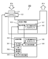
図1において、ガス保安装置100は、ガスが流れる流路101と、流路101を遮断する遮断弁102と、流路101に流れるガスの流量を計測する流量計測部103と、流量計測部103で計測した流量測定データを用いてガスの使用量を積算する制御回路104と、を備える。また、ガス保安装置100は、ガスの絶対圧力を測定する第1の圧力センサであるガス側絶対圧圧力センサ105と、大気の絶対圧力を測定する第2の圧力センサである大気側絶対圧圧力センサ106と、ガス雰囲気中に設置されている電子回路107と、所定の測定時間において、ガス側絶対圧圧力センサ105および大気側絶対圧圧力センサ106で測定した圧力値をそれぞれ所定個採取する圧力値採取部108と、を備える。さらに、ガス保安装置100は、圧力値採取部108で採取されたそれぞれの圧力値の平均値を算出し、その差分からガス供給圧を算出するガス圧力判定部109を備える。
In FIG. 1, the gas safety device 100 includes a flow path 101 through which gas flows, a shutoff valve 102 that shuts off the flow path 101, a flow rate measuring unit 103 that measures the flow rate of gas flowing through the flow path 101, and a flow rate measuring unit 103. A control circuit 104 that integrates the amount of gas used using the flow rate measurement data measured in 1 is provided. Further, the gas safety device 100 includes a gas side absolute pressure pressure sensor 105 which is a first pressure sensor for measuring the absolute pressure of gas, and an atmospheric side absolute pressure pressure which is a second pressure sensor for measuring the absolute pressure of the atmosphere. A pressure that collects a predetermined number of pressure values measured by the sensor 106, the electronic circuit 107 installed in the gas atmosphere, and the gas side absolute pressure pressure sensor 105 and the atmosphere side absolute pressure pressure sensor 106 at a predetermined measurement time. A value collecting unit 108 is provided. Further, the gas security device 100 includes a gas pressure determination unit 109 that calculates the average value of each pressure value collected by the pressure value collection unit 108 and calculates the gas supply pressure from the difference.
ガス側絶対圧圧力センサ105は、流路101の内部のガス雰囲気中に設置されている電子回路107上に電子部品として実装されており、制御回路104からの信号で流路101の内部のガスの絶対圧力を測定する。また、大気側絶対圧圧力センサ106は、流路101の外部の大気中に設置されている制御回路104上に電子部品として実装されており、制御回路104からの信号で大気の絶対圧力を測定する。
The gas-side absolute pressure pressure sensor 105 is mounted as an electronic component on the electronic circuit 107 installed in the gas atmosphere inside the flow path 101, and the gas inside the flow path 101 is received by a signal from the control circuit 104. Measure the absolute pressure of. Further, the atmospheric side absolute pressure pressure sensor 106 is mounted as an electronic component on a control circuit 104 installed in the atmosphere outside the flow path 101, and measures the absolute pressure of the atmosphere with a signal from the control circuit 104. To do.
次に、図2を用いて、具体的な動作説明を行う。ガス圧力判定部109による圧力測定は、予め定めた時間間隔T(例えば、2秒から10秒)で定期的に実行される。図2において、圧力測定時間T1、T2は圧力測定のタイミングを示しており、圧力測定時間T1において、圧力値採取部108によりガスの絶対圧力の圧力値がn個採取され、大気の絶対圧力の圧力値がm個採取される。
Next, a specific operation explanation will be given with reference to FIG. The pressure measurement by the gas pressure determination unit 109 is periodically executed at a predetermined time interval T (for example, 2 to 10 seconds). In FIG. 2, the pressure measurement times T1 and T2 indicate the timing of the pressure measurement. At the pressure measurement time T1, n pressure values of the absolute pressure of the gas are collected by the pressure value sampling unit 108, and the absolute pressure of the atmosphere is measured. M pressure values are collected.
即ち、圧力測定時間T1において、第1の圧力センサであるガス側絶対圧圧力センサ105で所定間隔(例えば、5ms)毎に圧力値Pg(1)、Pg(2)、・・・Pg(n-1)、Pg(n)の計n個(例えば、32個)の圧力値が測定され、圧力値採取部108で採取される。また、圧力測定時間T1において、第2の圧力センサである大気側絶対圧圧力センサ106により、所定間隔(例えば、5ms)毎に圧力値Pa(1)、Pa(2)、・・・Pa(m-1)、Pa(m)の計m個(例えば、32個)の圧力値が測定され、圧力値採取部108で採取される。
That is, at the pressure measurement time T1, the pressure values Pg (1), Pg (2), ... Pg (n) are set at predetermined intervals (for example, 5 ms) by the gas side absolute pressure pressure sensor 105, which is the first pressure sensor. -1), a total of n (for example, 32) pressure values of Pg (n) are measured and collected by the pressure value collecting unit 108. Further, at the pressure measurement time T1, the pressure values Pa (1), Pa (2), ... Pa () are used at predetermined intervals (for example, 5 ms) by the atmospheric side absolute pressure pressure sensor 106 which is the second pressure sensor. A total of m (for example, 32) pressure values of m-1) and Pa (m) are measured and collected by the pressure value collecting unit 108.
そして、ガス圧力判定部109は、ガスの圧力値n個の平均で求めたガスの圧力値Pgと大気の圧力値m個の平均で求めた大気の圧力値Paの差分(Pg-Pa)をガス供給圧として算出する。
Then, the gas pressure determination unit 109 determines the difference (Pg-Pa) between the gas pressure value Pg obtained by averaging the n gas pressure values and the atmospheric pressure value Pa obtained by averaging the atmospheric pressure values m. Calculated as gas supply pressure.
制御回路104は、流量計測部103で計測した流量測定データやガス圧力判定部109で算出されたガス供給圧やその変化を判定し、ガス漏れ等の異常がないかを判定し、異常と判断した場合には、遮断弁102で流路101を遮断して、ガスの供給を停止する。
The control circuit 104 determines the flow rate measurement data measured by the flow rate measurement unit 103, the gas supply pressure calculated by the gas pressure determination unit 109, and its change, determines whether or not there is an abnormality such as a gas leak, and determines that the abnormality is present. If this happens, the shutoff valve 102 shuts off the flow path 101 to stop the gas supply.
以上のように、本実施の形態においては、絶対圧力を測定できる第1の圧力センサであるガス側絶対圧圧力センサ105が測定したn個の圧力値、及び絶対圧力を測定できる第2の圧力センサである大気側絶対圧圧力センサ106が測定したm個の圧力値の平均値を用いてガス供給圧の変動を検知している。そのため、第1の圧力センサおよび第2の圧力センサの個体ばらつきや測定タイミングの誤差による測定精度の改善ができるとともに、差圧測定型の圧力センサを用いる場合に必要な貫通孔が不要となる。そのため、ガス保安装置の周囲が高温になってもガスが噴出することを防止でき、より安全性の高いガス保安装置が実現できる。
As described above, in the present embodiment, the n pressure values measured by the gas side absolute pressure pressure sensor 105, which is the first pressure sensor capable of measuring the absolute pressure, and the second pressure capable of measuring the absolute pressure. Fluctuations in the gas supply pressure are detected using the average value of m pressure values measured by the atmospheric side absolute pressure pressure sensor 106, which is a sensor. Therefore, the measurement accuracy can be improved due to the individual variation of the first pressure sensor and the second pressure sensor and the error of the measurement timing, and the through hole required when using the differential pressure measurement type pressure sensor becomes unnecessary. Therefore, it is possible to prevent gas from being ejected even when the temperature around the gas security device becomes high, and a gas security device with higher safety can be realized.
なお、本実施の形態において、圧力値の平均値を使用する構成で説明したが、平均値の代わりに中央値を使用しても同等に作用させることができる。
Although the configuration using the average value of the pressure values has been described in the present embodiment, the median value can be used instead of the average value to achieve the same effect.
なお、本実施の形態において、流量計測部を超音波流量計測として使用しても同等に作用させることができる。
In the present embodiment, even if the flow rate measuring unit is used for ultrasonic flow rate measurement, it can operate in the same manner.
また、本実施の形態では、ガスの圧力値の測定個数(n)と大気の圧力値の測定個数(m)を同じ32個として説明したが、圧力変動やノイズの影響など測定環境等に応じて異なる個数にしても良い。或いは、変動の少ないことが予想される大気の絶対圧力の測定個数(m個)はガスの絶対圧力の測定個数(n個)よりも少なくしても良く、この場合、第2の圧力センサである大気側絶対圧圧力センサ106による消費電力を少なくすることができる。
Further, in the present embodiment, the number of measured gas pressure values (n) and the number of measured atmospheric pressure values (m) are the same 32, but depending on the measurement environment such as the influence of pressure fluctuation and noise. The number may be different. Alternatively, the number of measured absolute pressures (m) of the atmosphere, which is expected to have little fluctuation, may be less than the number of measured absolute pressures of gas (n). In this case, the second pressure sensor The power consumption by a certain atmospheric side absolute pressure pressure sensor 106 can be reduced.
なお、本実施の形態において、第1の圧力センサであるガス側絶対圧圧力センサ105を流路101の内部のガス雰囲気中に設置されている電子回路107上に実装する構成として説明したが、流路内であれば何処に実装してもよいことはいうまでもない。また、大気側絶対圧圧力センサ106を流路101の外部の大気中に設置されている制御回路104上に実装する構成として説明したが、大気圧を測定できれば実装する場所に制限はない。
In the present embodiment, the gas side absolute pressure sensor 105, which is the first pressure sensor, has been described as a configuration in which the gas side absolute pressure sensor 105 is mounted on the electronic circuit 107 installed in the gas atmosphere inside the flow path 101. Needless to say, it may be mounted anywhere in the flow path. Further, although the configuration has been described in which the atmospheric side absolute pressure pressure sensor 106 is mounted on the control circuit 104 installed in the atmosphere outside the flow path 101, there is no limitation on the mounting location as long as the atmospheric pressure can be measured.
(第2の実施の形態)
以下、第2の実施の形態について、図3~図4を用いて説明する。なお、図3おいて、図1で説明した同一の構成要素については同一符号で示す。 (Second Embodiment)
Hereinafter, the second embodiment will be described with reference to FIGS. 3 to 4. In FIG. 3, the same components described with reference to FIG. 1 are indicated by the same reference numerals.
以下、第2の実施の形態について、図3~図4を用いて説明する。なお、図3おいて、図1で説明した同一の構成要素については同一符号で示す。 (Second Embodiment)
Hereinafter, the second embodiment will be described with reference to FIGS. 3 to 4. In FIG. 3, the same components described with reference to FIG. 1 are indicated by the same reference numerals.
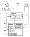
図3において、ガス保安装置200は、ガスが流れる流路101と、流路101を遮断する遮断弁102と、流路101に流れるガスの流量を計測する流量計測部103と、流量計測部103で計測した流量測定データを用いてガスの使用量を積算する制御回路204と、を備える。また、ガス保安装置200は、ガスの絶対圧力を測定する第1の圧力センサであるガス側絶対圧圧力センサ105と、大気の絶対圧力を測定する第2の圧力センサである大気側絶対圧圧力センサ106と、ガス雰囲気中に設置されている電子回路107と、を備える。さらに、ガス保安装置200は、所定の測定時間において、ガス側絶対圧圧力センサ105および大気側絶対圧圧力センサ106で同じタイミングで測定された圧力値の差分値をn個採取する差圧値採取部201と、差圧値採取部201で採取されたn個の差圧値の平均値からガス供給圧を算出するガス圧力判定部209を備える。
In FIG. 3, the gas safety device 200 includes a flow path 101 through which gas flows, a shutoff valve 102 that shuts off the flow path 101, a flow rate measuring unit 103 that measures the flow rate of gas flowing through the flow path 101, and a flow rate measuring unit 103. It is provided with a control circuit 204 for integrating the amount of gas used using the flow rate measurement data measured in. Further, the gas safety device 200 includes a gas-side absolute pressure pressure sensor 105, which is a first pressure sensor for measuring the absolute pressure of gas, and an atmospheric-side absolute pressure pressure, which is a second pressure sensor for measuring the absolute pressure of the atmosphere. It includes a sensor 106 and an electronic circuit 107 installed in a gas atmosphere. Further, the gas safety device 200 collects n differential pressure values measured at the same timing by the gas side absolute pressure pressure sensor 105 and the atmospheric side absolute pressure pressure sensor 106 at a predetermined measurement time. A unit 201 and a gas pressure determination unit 209 that calculates a gas supply pressure from the average value of n differential pressure values collected by the differential pressure value collecting unit 201 are provided.
次に、図4を用いて、具体的な動作説明を行う。なお、図2で説明した同一構成要素については同一符号で示す。
Next, a specific operation explanation will be given with reference to FIG. The same components described with reference to FIG. 2 are designated by the same reference numerals.
ガス圧力判定部209による圧力測定は、予め定めた時間間隔T(例えば、2秒から10秒)で定期的に実行される。図4において、圧力測定時間T1、T2は圧力測定のタイミングを示しており、圧力測定時間T1において、差圧値採取部201によりガスの絶対圧力の圧力値と大気の絶対圧力の圧力値との差圧値がn個採取される。
The pressure measurement by the gas pressure determination unit 209 is periodically executed at a predetermined time interval T (for example, 2 to 10 seconds). In FIG. 4, the pressure measurement times T1 and T2 indicate the timing of the pressure measurement, and at the pressure measurement time T1, the pressure value of the absolute pressure of the gas and the pressure value of the absolute pressure of the atmosphere are set by the differential pressure value sampling unit 201. N differential pressure values are collected.
第1の実施の形態との差異は、ガス側絶対圧圧力センサ105と大気側絶対圧圧力センサ106により同じタイミングで測定した、ガスの圧力値と大気の圧力値の差分を圧力値採取部108でn個採取する点である。
The difference from the first embodiment is that the difference between the gas pressure value and the atmospheric pressure value measured at the same timing by the gas side absolute pressure pressure sensor 105 and the atmospheric side absolute pressure pressure sensor 106 is measured by the pressure value sampling unit 108. It is a point to collect n pieces at.
即ち、圧力測定時間T1において、第1の圧力センサであるガス側絶対圧圧力センサ105により、所定間隔(例えば、5ms)毎に圧力値Pg(1)、Pg(2)、・・・Pg(n-1)、Pg(n)の計n個の圧力値が測定される。一方、第2の圧力センサである大気側絶対圧圧力センサ106では、ガス側絶対圧圧力センサ105による各測定と同じタイミングで圧力値Pa(1)、Pa(2)・・・Pa(n-1)、Pa(n)の計n個(例えば、32個)の圧力値が測定される。さらに、同じタイミングで測定された圧力値同士の差分値ΔP(1)=Pg(1)-Pa(1)、ΔP(2)=Pg(2)-Pa(2)、・・・ΔP(n-1)=Pg(n-1)-Pa(n-1)、ΔP(n)=Pg(n)-Pa(n)を算出する。
That is, at the pressure measurement time T1, the pressure values Pg (1), Pg (2), ... Pg (1), ... Pg (2), ... Pg (1), Pg (2), ... Pg (1), Pg (2), ... A total of n pressure values of n-1) and Pg (n) are measured. On the other hand, in the atmospheric side absolute pressure pressure sensor 106, which is the second pressure sensor, the pressure values Pa (1), Pa (2) ... Pa (n−) at the same timing as each measurement by the gas side absolute pressure pressure sensor 105. 1), Pa (n), a total of n pressure values (for example, 32 pressure values) are measured. Further, the difference values between the pressure values measured at the same timing ΔP (1) = Pg (1) -Pa (1), ΔP (2) = Pg (2) -Pa (2), ... ΔP (n) -1) = Pg (n-1) -Pa (n-1), ΔP (n) = Pg (n) -Pa (n) is calculated.
そして、ガス圧力判定部209は、n個の差分値を平均してガス供給圧を算出する。
Then, the gas pressure determination unit 209 calculates the gas supply pressure by averaging n difference values.
制御回路204は、流量計測部103で計測した流量測定データやガス圧力判定部209で算出されたガス供給圧やその変化を判定し、ガス漏れ等の異常がないかを判定し、異常と判断した場合には、遮断弁102で流路101を遮断して、ガスの供給を停止する。
The control circuit 204 determines the flow rate measurement data measured by the flow rate measurement unit 103, the gas supply pressure calculated by the gas pressure determination unit 209, and its change, determines whether or not there is an abnormality such as a gas leak, and determines that the abnormality is present. If this happens, the shutoff valve 102 shuts off the flow path 101 to stop the gas supply.
以上のように、本実施の形態においては、絶対圧力を測定できる第1の圧力センサであるガス側絶対圧圧力センサ105と第2の圧力センサである大気側絶対圧圧力センサ106によって同じタイミングで測定された圧力値の差分の平均値を用いてガス供給圧の変動を検知する。そのため、第1の圧力センサおよび第2の圧力センサの個体ばらつきや測定タイミングの誤差による測定精度の改善ができるとともに、差圧測定型の圧力センサを用いる場合に必要な貫通孔が不要となる。そのため、ガス保安装置の周囲が高温になってもガスが噴出することを防止でき、より安全性の高いガス保安装置が実現できる。
As described above, in the present embodiment, the gas side absolute pressure pressure sensor 105, which is the first pressure sensor, and the atmospheric side absolute pressure pressure sensor 106, which is the second pressure sensor, can measure the absolute pressure at the same timing. Fluctuations in gas supply pressure are detected using the average value of the difference between the measured pressure values. Therefore, the measurement accuracy can be improved due to the individual variation of the first pressure sensor and the second pressure sensor and the error of the measurement timing, and the through hole required when using the differential pressure measurement type pressure sensor becomes unnecessary. Therefore, it is possible to prevent gas from being ejected even when the temperature around the gas security device becomes high, and a gas security device with higher safety can be realized.
なお、本実施の形態において、圧力値の平均値を使用する構成で説明したが、平均値の代わりに中央値を使用しても同等に作用させることができる。
Although the configuration using the average value of the pressure values has been described in the present embodiment, the median value can be used instead of the average value to achieve the same effect.
(第3の実施の形態)
以下、第3の実施の形態について、図5~図6を用いて説明する。なお、図5において、図1で説明した同一の構成要素については同一符号で示す。 (Third Embodiment)
Hereinafter, the third embodiment will be described with reference to FIGS. 5 to 6. In FIG. 5, the same components described with reference to FIG. 1 are indicated by the same reference numerals.
以下、第3の実施の形態について、図5~図6を用いて説明する。なお、図5において、図1で説明した同一の構成要素については同一符号で示す。 (Third Embodiment)
Hereinafter, the third embodiment will be described with reference to FIGS. 5 to 6. In FIG. 5, the same components described with reference to FIG. 1 are indicated by the same reference numerals.
図5において、ガス保安装置300は、ガスが流れる流路101と、流路101を遮断する遮断弁102と、流路101に流れるガスの流量を計測する流量計測部103と、流量計測部103で計測した流量測定データを用いてガスの使用量を積算する制御回路304と、を備える。また、ガス保安装置300は、ガスの絶対圧力を測定する第1の圧力センサであるガス側絶対圧圧力センサ105と、大気の絶対圧力を測定する第2の圧力センサである大気側絶対圧圧力センサ106と、ガス雰囲気中に設置されている電子回路107と、を備える。さらに、ガス保安装置300は、任意の計測時間において、ガス側絶対圧圧力センサ105および大気側絶対圧圧力センサ106で測定された圧力値をそれぞれ所定個採取する圧力値採取部108と、圧力値比較部301と、異常値無視部302と、ガス圧力判定部309と、を備える。
In FIG. 5, the gas safety device 300 includes a flow path 101 through which gas flows, a shutoff valve 102 that shuts off the flow path 101, a flow rate measuring unit 103 that measures the flow rate of gas flowing through the flow path 101, and a flow rate measuring unit 103. The control circuit 304, which integrates the amount of gas used by using the flow rate measurement data measured in 1. Further, the gas safety device 300 includes a gas-side absolute pressure pressure sensor 105, which is a first pressure sensor for measuring the absolute pressure of gas, and an atmospheric-side absolute pressure pressure, which is a second pressure sensor for measuring the absolute pressure of the atmosphere. It includes a sensor 106 and an electronic circuit 107 installed in a gas atmosphere. Further, the gas safety device 300 has a pressure value sampling unit 108 that collects predetermined pressure values measured by the gas side absolute pressure pressure sensor 105 and the atmosphere side absolute pressure pressure sensor 106 at an arbitrary measurement time, and a pressure value. A comparison unit 301, an abnormal value ignoring unit 302, and a gas pressure determination unit 309 are provided.
ここで、圧力値比較部301は、圧力値採取部108で得られたそれぞれの圧力値を比較する。異常値無視部302は、圧力値比較部301において、値が他の圧力値と明らかに異なると判断された値は異常値と判断する。その判断では、例えば、3つの連続する圧力の測定値を比較し、その1つの測定値が他の測定値と1000パスカル以上の差がある場合、或いは、その測定値が全体の平均に対しての所定割合以上の差がある場合、その測定値を異常値であると判定する。この判断に基づいて異常値を除いた圧力値をガス圧力判定部309に出力する。ガス圧力判定部309は、異常値無視部302から出力されたガスの圧力値と大気の圧力値でそれぞれの平均値を計算し、平均値の差分をガス供給圧として算出する。
Here, the pressure value comparison unit 301 compares each pressure value obtained by the pressure value collection unit 108. The outlier ignoring unit 302 determines that the value determined by the pressure value comparing unit 301 to be clearly different from the other pressure values is an outlier. In that judgment, for example, three consecutive pressure measurements are compared and one measurement is more than 1000 pascals different from the other, or that measurement is relative to the overall average. If there is a difference of more than a predetermined ratio, the measured value is determined to be an abnormal value. Based on this determination, the pressure value excluding the abnormal value is output to the gas pressure determination unit 309. The gas pressure determination unit 309 calculates the average value of each of the gas pressure value and the atmospheric pressure value output from the abnormal value ignoring unit 302, and calculates the difference between the average values as the gas supply pressure.
次に、図6を用いて、具体的な動作説明を行う。図2、図4で説明した同一の構成要素については同一符号で示す。
Next, a specific operation explanation will be given with reference to FIG. The same components described with reference to FIGS. 2 and 4 are designated by the same reference numerals.
ガス圧力判定部309による圧力測定は、予め定めた時間間隔T(例えば、2秒から10秒)で定期的に実行される。図6において、圧力測定時間T1、T2は圧力測定のタイミングを示しており、圧力測定時間T1において、ガス側絶対圧圧力センサ105によりガスの絶対圧力がn個測定され、大気側絶対圧圧力センサ106により大気の絶対圧力がm個測定され、ガスの圧力値n個と大気の圧力値m個が圧力値採取部108で採取される。
The pressure measurement by the gas pressure determination unit 309 is periodically executed at a predetermined time interval T (for example, 2 seconds to 10 seconds). In FIG. 6, the pressure measurement times T1 and T2 indicate the timing of pressure measurement. At the pressure measurement time T1, n absolute pressures of gas are measured by the gas side absolute pressure pressure sensor 105, and the atmospheric side absolute pressure pressure sensor The absolute pressure of m is measured by 106, and n gas pressure values and m atmospheric pressure values are collected by the pressure value collecting unit 108.
即ち、圧力測定時間T1において、ガス側絶対圧圧力センサ105により、所定間隔(例えば、5ms)毎に圧力値Pg(1)、Pg(2)、・・・Pg(n-1)、Pg(n)の合計n個(例えば、32個)の圧力値が測定される。一方、大気側絶対圧圧力センサ106により、所定間隔(例えば、5ms)毎に圧力値Pa(1)、Pa(2)、・・・Pa(m-1)、Pa(m)の合計m個(例えば、32個)の圧力値が測定される。
That is, at the pressure measurement time T1, the pressure values Pg (1), Pg (2), ... Pg (n-1), Pg () are measured at predetermined intervals (for example, 5 ms) by the gas side absolute pressure pressure sensor 105. A total of n (for example, 32) pressure values of n) are measured. On the other hand, by the atmospheric side absolute pressure pressure sensor 106, a total of m pressure values Pa (1), Pa (2), ... Pa (m-1), Pa (m) are provided at predetermined intervals (for example, 5 ms). Pressure values (for example, 32) are measured.
そして、例えば、ガスの2回目の圧力値Pg(2)が、他の測定値と明らかに異なっており、圧力値比較部301で他の測定値との比較によって異常値と判断された場合、以下の処理を行う。すなわち、ガスの圧力測定時間T1では、異常値無視部302において、2回目の圧力値Pg(2)を除いたn-1個の圧力値がガス圧力判定部309に出力され、平均してガスの圧力値Pgが計算される。一方、大気の圧力値で異常な値が無かった場合にはm個の圧力値がガス圧力判定部309に出力され、ガス圧力判定部309ではm個の圧力値を平均して大気側圧力値Paが計算される。
Then, for example, when the second pressure value Pg (2) of the gas is clearly different from the other measured values and is determined by the pressure value comparing unit 301 to be an abnormal value by comparison with the other measured values. Perform the following processing. That is, at the gas pressure measurement time T1, n-1 pressure values excluding the second pressure value Pg (2) are output to the gas pressure determination unit 309 in the abnormal value ignoring unit 302, and the gas is averaged. The pressure value Pg of is calculated. On the other hand, if there is no abnormal value in the atmospheric pressure value, m pressure values are output to the gas pressure determination unit 309, and the gas pressure determination unit 309 averages the m pressure values to the atmospheric pressure value. Pa is calculated.
そして、ガス圧力判定部309は、異常値である圧力値Pg(2)を除いたn-1個の圧力値を平均して求めたガス側圧力値Pgと大気側の絶対圧のm個の圧力値を平均しても求めた大気側圧力値Paの差分(Pg-Pa)をガス供給圧として算出する。
Then, the gas pressure determination unit 309 has the gas side pressure value Pg obtained by averaging the n-1 pressure values excluding the abnormal pressure value Pg (2) and m of the atmospheric side absolute pressure. The difference (Pg-Pa) of the atmospheric pressure value Pa obtained by averaging the pressure values is calculated as the gas supply pressure.
制御回路304は、流量計測部103で計測した流量測定データやガス圧力判定部309で算出されたガス供給圧やその変化を判定し、ガス漏れ等の異常がないかを判定し、異常と判断した場合には、遮断弁102で流路101を遮断して、ガスの供給を停止する。
The control circuit 304 determines the flow rate measurement data measured by the flow rate measurement unit 103, the gas supply pressure calculated by the gas pressure determination unit 309, and its change, determines whether there is an abnormality such as a gas leak, and determines that the abnormality is present. If this happens, the shutoff valve 102 shuts off the flow path 101 to stop the gas supply.
以上のように、本実施の形態においては、絶対圧力を計測できる第1の圧力センサであるガス側絶対圧圧力センサ105と第2の圧力センサである大気側絶対圧圧力センサ106を用いてガス供給圧の変動を検知する場合に、異常な測定値を除外する。この構成により、第1の圧力センサおよび第2の圧力センサの個体ばらつきや測定タイミングの誤差による測定精度の改善ができるとともに、差圧測定型の圧力センサを用いる場合に必要な貫通孔が不要となる。そのため、ガス保安装置の周囲が高温になってもガスが噴出することを防止でき、より安全性の高いガス保安装置が実現できる。
As described above, in the present embodiment, the gas is used by using the gas side absolute pressure pressure sensor 105 which is the first pressure sensor capable of measuring the absolute pressure and the atmospheric side absolute pressure pressure sensor 106 which is the second pressure sensor. Exclude abnormal measurements when detecting fluctuations in supply pressure. With this configuration, it is possible to improve the measurement accuracy due to individual variations of the first pressure sensor and the second pressure sensor and errors in measurement timing, and it is not necessary to have a through hole required when using a differential pressure measurement type pressure sensor. Become. Therefore, it is possible to prevent gas from being ejected even when the temperature around the gas security device becomes high, and a gas security device with higher safety can be realized.
(第4の実施の形態)
以下、第4の実施の形態について、図7~図8を用いて説明する。なお、図7おいて、図1、図3で説明した同一の構成要素については同一番号で示す。 (Fourth Embodiment)
Hereinafter, the fourth embodiment will be described with reference to FIGS. 7 to 8. In FIG. 7, the same components described with reference to FIGS. 1 and 3 are indicated by the same numbers.
以下、第4の実施の形態について、図7~図8を用いて説明する。なお、図7おいて、図1、図3で説明した同一の構成要素については同一番号で示す。 (Fourth Embodiment)
Hereinafter, the fourth embodiment will be described with reference to FIGS. 7 to 8. In FIG. 7, the same components described with reference to FIGS. 1 and 3 are indicated by the same numbers.
図7において、ガス保安装置400は、ガスが流れる流路101と、流路101を遮断する遮断弁102と、流路101に流れるガスの流量を計測する流量計測部103と、流量計測部103で計測した流量測定データを用いてガスの使用量を積算する制御回路404と、を備える。また、ガス保安装置400は、ガスの絶対圧力を測定する第1の圧力センサであるガス側絶対圧圧力センサ105と、大気の絶対圧力を測定する第2の圧力センサである大気側絶対圧圧力センサ106と、ガス雰囲気中に設置されている電子回路107と、を備える。さらに、ガス保安装置400は、所定の測定時間において、ガス側絶対圧圧力センサ105および大気側絶対圧圧力センサ106で同じタイミングで測定された圧力値の差分をn個採取する差圧値採取部201と、差圧値比較部401と、差圧異常値無視部402と、ガス圧力判定部409と、を備える。
In FIG. 7, the gas safety device 400 includes a flow path 101 through which gas flows, a shutoff valve 102 that shuts off the flow path 101, a flow rate measuring unit 103 that measures the flow rate of gas flowing through the flow path 101, and a flow rate measuring unit 103. A control circuit 404 that integrates the amount of gas used using the flow rate measurement data measured in 1 is provided. Further, the gas safety device 400 includes a gas-side absolute pressure pressure sensor 105, which is a first pressure sensor for measuring the absolute pressure of gas, and an atmospheric-side absolute pressure pressure, which is a second pressure sensor for measuring the absolute pressure of the atmosphere. It includes a sensor 106 and an electronic circuit 107 installed in a gas atmosphere. Further, the gas safety device 400 is a differential pressure value collecting unit that collects n differences of pressure values measured at the same timing by the gas side absolute pressure pressure sensor 105 and the atmospheric side absolute pressure pressure sensor 106 at a predetermined measurement time. It includes 201, a differential pressure value comparison unit 401, a differential pressure abnormal value ignoring unit 402, and a gas pressure determination unit 409.
ここで、差圧値比較部401は、差圧値採取部201で得られたn個の差圧値をそれぞれ比較するする。差圧異常値無視部402は、差圧値比較部401において、値が他の差圧値と明らかに異なると判断された値は異常値として判断する。その判断では、例えば、3つの連続する圧力値による差圧値を比較し、その1つが他の差圧値と1000パスカル以上の差がある、或いは、全体の平均に対しての所定割合以上の差がある場合、その差圧値を異常値であると判定する。この異常値を除くn-1個の差圧値をガス圧力判定部409に出力する。
Here, the differential pressure value comparison unit 401 compares the n differential pressure values obtained by the differential pressure value collection unit 201. The differential pressure abnormal value ignoring unit 402 determines in the differential pressure value comparison unit 401 that the value is clearly different from the other differential pressure values as an abnormal value. In that judgment, for example, the differential pressure values of three consecutive pressure values are compared, and one of them has a difference of 1000 pascals or more from the other differential pressure values, or a predetermined ratio or more with respect to the overall average. If there is a difference, the differential pressure value is determined to be an abnormal value. The n-1 differential pressure values excluding this abnormal value are output to the gas pressure determination unit 409.
ガス圧力判定部409は、差圧値比較部401から出力されたn-1個の差圧値の平均値を計算してガス供給圧として算出する。
The gas pressure determination unit 409 calculates the average value of n-1 differential pressure values output from the differential pressure value comparison unit 401 and calculates it as the gas supply pressure.
次に、図8を用いて、具体的な動作説明を行う。図2、図4、図6で説明した同一構成要素については同一番号で示す。
Next, a specific operation explanation will be given with reference to FIG. The same components described in FIGS. 2, 4 and 6 are indicated by the same numbers.
ガス圧力判定部209による圧力測定は、予め定めた時間間隔T(例えば、2秒から10秒)で定期的に実行される。図8において、圧力測定時間T1、T2は圧力測定のタイミングを示しており、圧力測定時間T1において、差圧値採取部201によりガスの絶対圧力の圧力値と大気の絶対圧力の圧力値との差圧値がn個採取される。
The pressure measurement by the gas pressure determination unit 209 is periodically executed at a predetermined time interval T (for example, 2 seconds to 10 seconds). In FIG. 8, the pressure measurement times T1 and T2 indicate the timing of the pressure measurement, and at the pressure measurement time T1, the pressure value of the absolute pressure of the gas and the pressure value of the absolute pressure of the atmosphere are set by the differential pressure value sampling unit 201. N differential pressure values are collected.
即ち、圧力測定時間T1において、第1の圧力センサであるガス側絶対圧圧力センサ105により、所定間隔(例えば、5ms)毎に圧力値Pg(1)、Pg(2)、・・・Pg(n-1)、Pg(n)の計n個(例えば、32個)の圧力値が測定される。一方、第2の圧力センサである大気側絶対圧圧力センサ106では、ガス側絶対圧圧力センサ105による各測定と同じタイミングで圧力値Pa(1)、Pa(2)・・・Pa(n-1)、Pa(n)の計n個(例えば、32個)の圧力値が測定される。さらに、同じタイミングで測定された圧力値同士の差分値ΔP(1)=Pg(1)-Pa(1)、ΔP(2)=Pg(2)-Pa(2)、・・・ΔP(n-1)=Pg(n-1)-Pa(n-1)、ΔP(n)=Pg(n)-Pa(n)を算出する。
That is, at the pressure measurement time T1, the pressure values Pg (1), Pg (2), ... Pg (1), Pg (2), ... Pg (for example, 5 ms) by the gas side absolute pressure pressure sensor 105 which is the first pressure sensor. A total of n (for example, 32) pressure values of n-1) and Pg (n) are measured. On the other hand, in the atmospheric side absolute pressure pressure sensor 106, which is the second pressure sensor, the pressure values Pa (1), Pa (2) ... Pa (n−) at the same timing as each measurement by the gas side absolute pressure pressure sensor 105. 1), Pa (n), a total of n pressure values (for example, 32 pressure values) are measured. Further, the difference values between the pressure values measured at the same timing ΔP (1) = Pg (1) -Pa (1), ΔP (2) = Pg (2) -Pa (2), ... ΔP (n) -1) = Pg (n-1) -Pa (n-1), ΔP (n) = Pg (n) -Pa (n) is calculated.
ここで、例えば、ガス側の2回目の圧力値Pg(2)が、他の測定値と明らか異なっており、Pg(2)とPa(2)で算出された差圧値ΔP(2)が差圧値比較部401で他の値と比較によって異常値と判断された場合、以下の処理を行う。すなわち、ガスの圧力測定時間T1では、差圧異常値無視部402において、異常値と判定された2回目の差圧値ΔP(2)を除いたn-1個の差圧値がガス圧力判定部409に出力され、ガス圧力判定部409では、n-1個の差圧値の平均値をガス供給圧として算出する。
Here, for example, the second pressure value Pg (2) on the gas side is clearly different from the other measured values, and the differential pressure value ΔP (2) calculated by Pg (2) and Pa (2) is When the differential pressure value comparison unit 401 determines that the value is abnormal by comparing with another value, the following processing is performed. That is, in the gas pressure measurement time T1, the gas pressure determination is performed by n-1 differential pressure values excluding the second differential pressure value ΔP (2) determined to be an abnormal value in the differential pressure abnormal value ignoring unit 402. It is output to the unit 409, and the gas pressure determination unit 409 calculates the average value of n-1 differential pressure values as the gas supply pressure.
制御回路404は、流量計測部103で計測した流量測定データやガス圧力判定部409で算出されたガス供給圧やその変化を判定し、ガス漏れ等の異常がないかを判定し、異常と判断した場合には、遮断弁102で流路101を遮断して、ガスの供給を停止する。
The control circuit 404 determines the flow rate measurement data measured by the flow rate measurement unit 103, the gas supply pressure calculated by the gas pressure determination unit 409, and its change, determines whether there is an abnormality such as a gas leak, and determines that the abnormality is present. If this happens, the shutoff valve 102 shuts off the flow path 101 to stop the gas supply.
以上のように、本実施の形態においては、絶対圧力を計測できる第1の圧力センサであるガス側絶対圧圧力センサ105と第2の圧力センサである大気側絶対圧圧力センサ106を用い、同じタイミングで計測した圧力値の差圧値の内、異常な測定値を除いてガス供給圧を算出する。この構成により、ガス供給圧の変動を正確に検知することで、第1の圧力センサおよび第2の圧力センサの個体ばらつきや測定タイミングの誤差による測定精度の改善ができるとともに、差圧測定型の圧力センサを用いる場合に必要な貫通孔が不要となる。そのため、ガス保安装置の周囲が高温になってもガスが噴出することを防止でき、より安全性の高いガス保安装置が実現できる。
As described above, in the present embodiment, the gas side absolute pressure pressure sensor 105 which is the first pressure sensor capable of measuring the absolute pressure and the atmospheric side absolute pressure pressure sensor 106 which is the second pressure sensor are used and the same. The gas supply pressure is calculated by excluding abnormally measured values from the differential pressure values of the pressure values measured at the timing. With this configuration, by accurately detecting fluctuations in the gas supply pressure, it is possible to improve the measurement accuracy due to individual variations of the first pressure sensor and the second pressure sensor and errors in the measurement timing, and the differential pressure measurement type. The through hole required when using a pressure sensor becomes unnecessary. Therefore, it is possible to prevent gas from being ejected even when the temperature around the gas security device becomes high, and a gas security device with higher safety can be realized.
以上説明したように、第1の開示は、ガスを流すための流路と、流路を流れるガスの流量を測定するための流量計測部と、流路の内部に配置されガスの絶対圧力を測定する第1の圧力センサと、流路の外部に配置され大気圧の絶対圧力を測定する第2の圧力センサと、を備える。また、第1の圧力センサで測定された圧力値をn個採取し、第2の圧力センサで測定された圧力値をm個採取する圧力値採取部と、圧力値採取部で得られたそれぞれの圧力値の平均値の差からガス供給圧を算出するガス圧力判定部と、を備える。さらに、流路を遮断する遮断弁と、流量計測部を制御するとともに、流量計測部で測定した流量やガス圧力判定部で算出したガス供給圧から異常と判定した場合に遮断弁で流路を遮断する制御回路と、を備える。
As described above, in the first disclosure, a flow path for flowing a gas, a flow rate measuring unit for measuring the flow rate of the gas flowing through the flow path, and an absolute pressure of the gas arranged inside the flow path are measured. It includes a first pressure sensor for measuring and a second pressure sensor arranged outside the flow path for measuring the absolute pressure of atmospheric pressure. In addition, a pressure value collecting unit that collects n pressure values measured by the first pressure sensor and m pressure values measured by the second pressure sensor, and a pressure value collecting unit that collects m pressure values, respectively. It is provided with a gas pressure determination unit that calculates the gas supply pressure from the difference between the average values of the pressure values. Furthermore, the shutoff valve that shuts off the flow path and the flow rate measuring unit are controlled, and when an abnormality is determined from the flow rate measured by the flow rate measuring section and the gas supply pressure calculated by the gas pressure determination section, the flow path is cut off by the shutoff valve. A control circuit for shutting off is provided.
この構成により、絶対圧力を測定する第1の圧力センサと第2の圧力センサの平均値を用いてガス供給圧を検知するため、第1の圧力センサと第2の圧力センサの個体ばらつきや測定タイミングの誤差による測定精度の改善ができるとともに、差圧測定型の圧力センサを用いる場合に必要な貫通孔が不要となる。そのため、ガス保安装置の周囲が高温になってもガスが噴出することを防止でき、より安全性の高いガス保安装置が実現できる。
With this configuration, the gas supply pressure is detected using the average value of the first pressure sensor and the second pressure sensor that measure the absolute pressure, so that the individual variation and measurement of the first pressure sensor and the second pressure sensor are performed. The measurement accuracy can be improved due to the timing error, and the through hole required when using the differential pressure measurement type pressure sensor becomes unnecessary. Therefore, it is possible to prevent gas from being ejected even when the temperature around the gas security device becomes high, and a gas security device with higher safety can be realized.
第2の開示は、特に第1の開示において、圧力値採取部で採取された第1の圧力センサおよび第2の圧力センサのそれぞれの圧力値と平均値を比較する平均値比較部を備える。さらに、ガス圧力判定部は、平均値比較部において、圧力値採取部値で採取された圧力値のうち平均値と明らかに異なると判断された圧力値を除いて平均値を算出する構成としてもよい。
The second disclosure, particularly in the first disclosure, includes an average value comparison unit that compares the pressure values and average values of the first pressure sensor and the second pressure sensor collected by the pressure value collection unit. Further, the gas pressure determination unit may be configured to calculate the average value by excluding the pressure value determined to be clearly different from the average value among the pressure values collected by the pressure value collection unit value in the average value comparison unit. Good.
この構成により、第1の圧力センサと第2の圧力センサがそれぞれ測定した圧力値の平均値を用いてガス供給圧を検知するため、第1の圧力センサおよび第2の圧力センサの個体ばらつきや測定タイミングの誤差による測定精度の改善ができるとともに、差圧測定型の圧力センサを用いる場合に必要な貫通孔が不要となる。そのため、ガス保安装置の周囲が高温になってもガスが噴出することを防止でき、より安全性の高いガス保安装置が実現できる。
With this configuration, the gas supply pressure is detected using the average value of the pressure values measured by the first pressure sensor and the second pressure sensor, respectively, so that individual variations of the first pressure sensor and the second pressure sensor may occur. The measurement accuracy can be improved due to the error in the measurement timing, and the through hole required when using the differential pressure measurement type pressure sensor becomes unnecessary. Therefore, it is possible to prevent gas from being ejected even when the temperature around the gas security device becomes high, and a gas security device with higher safety can be realized.
第3の開示は、特に第1または2のいずれか1つの開示において、流量計測部が、流路の内部に配置された計測回路を有し、第1の圧力センサは計測回路上に構成され、制御回路が、流路の外部に配置され、第2の圧力センサは制御回路上に配置されてもよい。
A third disclosure, particularly in any one of the first or second disclosures, is that the flow rate measuring unit has a measuring circuit arranged inside the flow path, and the first pressure sensor is configured on the measuring circuit. , The control circuit may be arranged outside the flow path and the second pressure sensor may be arranged on the control circuit.
第4の開示は、特に第3の開示において、流量計測部が、超音波センサと超音波センサを駆動して流量計測を行う計測回路を一体とした超音波流量計測部を備え、超音波流量計測部をガス雰囲気中に設置するとともに、超音波流量計測部に第1の圧力センサを備え、制御回路で超音波流量計測部を制御することによって、第1の圧力センサも制御する構成としてもよい。
In the fourth disclosure, particularly in the third disclosure, the flow rate measuring unit includes an ultrasonic flow rate measuring unit that integrates an ultrasonic sensor and a measuring circuit that drives the ultrasonic sensor to measure the flow rate, and the ultrasonic flow rate. In addition to installing the measuring unit in a gas atmosphere, the ultrasonic flow measuring unit is provided with a first pressure sensor, and by controlling the ultrasonic flow measuring unit with a control circuit, the first pressure sensor can also be controlled. Good.
第5の開示は、ガスを流すための流路と、流路を流れるガスの流量を測定するための流量計測部と、流路内部に配置され、ガスの絶対圧力を測定する第1の圧力センサと、流路外部に配置され、大気圧の絶対圧力を測定する第2の圧力センサと、を備える。また、第1の圧力センサで測定された圧力値と第1の圧力センサの測定の同じタイミングで第2の圧力センサで測定された圧力値の差圧値をn個採取する差圧値採取部と、差圧値採取部で採取したn個の差圧値の平均値でガス供給圧を算出するガス圧力判定部と、を備える。さらに、流路を遮断する遮断弁と、流量計測部を制御するとともに、流量計測部で測定した流量やガス圧力判定部で算出したガス供給圧から異常と判定した場合に遮断弁で流路を遮断する制御回路と、を備える。
The fifth disclosure is a flow path for flowing a gas, a flow rate measuring unit for measuring the flow rate of the gas flowing through the flow path, and a first pressure arranged inside the flow path for measuring the absolute pressure of the gas. It includes a sensor and a second pressure sensor that is arranged outside the flow path and measures the absolute pressure of atmospheric pressure. In addition, a differential pressure value collecting unit that collects n differential pressure values of the pressure values measured by the second pressure sensor at the same timing as the pressure value measured by the first pressure sensor and the measurement of the first pressure sensor. A gas pressure determination unit that calculates the gas supply pressure based on the average value of n differential pressure values collected by the differential pressure value collection unit is provided. Furthermore, the shutoff valve that shuts off the flow path and the flow rate measuring unit are controlled, and when an abnormality is determined from the flow rate measured by the flow rate measuring section and the gas supply pressure calculated by the gas pressure determination section, the flow path is cut off by the shutoff valve. A control circuit for shutting off is provided.
この構成により、絶対圧力を測定する第1の圧力センサおよび第2の圧力センサの平均値を用いてガス供給圧を検知するため、第1の圧力センサおよび第2の圧力センサの個体ばらつきや測定タイミングの誤差による測定精度の改善ができるとともに、差圧測定型の圧力センサを用いる場合に必要な貫通孔が不要となる。そのため、ガス保安装置の周囲が高温になってもガスが噴出することを防止でき、より安全性の高いガス保安装置が実現できる。
With this configuration, since the gas supply pressure is detected using the average value of the first pressure sensor and the second pressure sensor that measure the absolute pressure, individual variation and measurement of the first pressure sensor and the second pressure sensor are performed. The measurement accuracy can be improved due to the timing error, and the through hole required when using the differential pressure measurement type pressure sensor becomes unnecessary. Therefore, it is possible to prevent gas from being ejected even when the temperature around the gas security device becomes high, and a gas security device with higher safety can be realized.
第6の開示は、特に第5の開示において、差圧値採取部で採取された差圧値を比較する差圧値比較部を備え、ガス圧力判定部が、差圧値比較部において、差圧値採取部で採取された差圧値のうち他の差圧値と明らかに異なると判断された差圧値を除いて平均値を算出する構成としてもよい。
The sixth disclosure, particularly in the fifth disclosure, includes a differential pressure value comparison unit that compares the differential pressure values collected by the differential pressure value collection unit, and the gas pressure determination unit makes a difference in the differential pressure value comparison unit. The average value may be calculated by excluding the differential pressure value determined to be clearly different from the other differential pressure values among the differential pressure values collected by the pressure value collecting unit.
この構成により、絶対圧力を測定する第1の圧力センサおよび第2の圧力センサの平均値を用いてガス供給圧を検知するため、第1の圧力センサおよび第2の圧力センサの個体ばらつきや測定タイミングの誤差による測定精度の改善ができるとともに、差圧測定型の圧力センサを用いる場合に必要な貫通孔が不要となる。そのため、ガス保安装置の周囲が高温になってもガスが噴出することを防止でき、より安全性の高いガス保安装置が実現できる。
With this configuration, since the gas supply pressure is detected using the average value of the first pressure sensor and the second pressure sensor that measure the absolute pressure, individual variation and measurement of the first pressure sensor and the second pressure sensor are performed. The measurement accuracy can be improved due to the timing error, and the through hole required when using the differential pressure measurement type pressure sensor becomes unnecessary. Therefore, it is possible to prevent gas from being ejected even when the temperature around the gas security device becomes high, and a gas security device with higher safety can be realized.
第7の開示は、特に第5または6の何れか1つの開示において、流量計測部が、流路の内部に配置された計測回路を有し、第1の圧力センサは計測回路上に構成され、制御回路が、流路の外部に配置され、第2の圧力センサは制御回路上に配置された構成としてもよい。
In the seventh disclosure, particularly in any one of the fifth or sixth disclosure, the flow rate measuring unit has a measuring circuit arranged inside the flow path, and the first pressure sensor is configured on the measuring circuit. , The control circuit may be arranged outside the flow path, and the second pressure sensor may be arranged on the control circuit.
第8の開示は、特に第7の開示において、流量計測部が、超音波センサと超音波センサを駆動して流量計測を行う計測回路を一体とした超音波流量計測部を備え、超音波流量計測部をガス雰囲気中に設置するとともに、超音波流量計測部に第1の圧力センサを備え、制御回路で超音波流量計測部を制御することによって、第1の圧力センサも制御する構成としてもよい。
In the eighth disclosure, particularly in the seventh disclosure, the flow rate measuring unit includes an ultrasonic flow rate measuring unit that integrates an ultrasonic sensor and a measuring circuit that drives the ultrasonic sensor to measure the flow rate, and the ultrasonic flow rate. In addition to installing the measuring unit in a gas atmosphere, the ultrasonic flow measuring unit is provided with a first pressure sensor, and by controlling the ultrasonic flow measuring unit with a control circuit, the first pressure sensor can also be controlled. Good.
本開示は、ガス保安装置は、ガス保安装置の周囲が高温になっても圧力センサ用の貫通穴からガスが噴出することを防止できるため、より安全性を向上できるだけでなく、より安価なガス保安装置が実現でき、一般家庭用及び業務用ガスメータ等の用途に適用できる。
According to the present disclosure, the gas security device can prevent gas from being ejected from the through hole for the pressure sensor even when the temperature around the gas security device becomes high, so that not only the safety can be improved but also the gas is cheaper. A security device can be realized, and it can be applied to applications such as general household and commercial gas meters.
100、200、300、400 ガス保安装置
101 流路
102 遮断弁
103 流量計測部
104、204、304、404 制御回路
105 ガス側絶対圧圧力センサ(第1の圧力センサ)
106 大気側絶対圧圧力センサ(第2の圧力センサ)
107 電子回路(計測回路)
108 圧力値採取部
109、209、309、409 ガス圧力判定部
201 差圧値採取部
301 圧力値比較部
302 異常値無視部
401 差圧値比較部
402 差圧異常値無視部 100, 200, 300, 400Gas security device 101 Flow path 102 Shutoff valve 103 Flow rate measuring unit 104, 204, 304, 404 Control circuit 105 Gas side absolute pressure pressure sensor (first pressure sensor)
106 Atmospheric side absolute pressure pressure sensor (second pressure sensor)
107 Electronic circuit (measurement circuit)
108 Pressure value sampling unit 109, 209, 309, 409 Gas pressure judgment unit 201 Differential pressure value sampling unit 301 Pressure value comparison unit 302 Abnormal value ignoring unit 401 Differential pressure value comparison unit 402 Differential pressure abnormal value ignoring unit
101 流路
102 遮断弁
103 流量計測部
104、204、304、404 制御回路
105 ガス側絶対圧圧力センサ(第1の圧力センサ)
106 大気側絶対圧圧力センサ(第2の圧力センサ)
107 電子回路(計測回路)
108 圧力値採取部
109、209、309、409 ガス圧力判定部
201 差圧値採取部
301 圧力値比較部
302 異常値無視部
401 差圧値比較部
402 差圧異常値無視部 100, 200, 300, 400
106 Atmospheric side absolute pressure pressure sensor (second pressure sensor)
107 Electronic circuit (measurement circuit)
108 Pressure
Claims (8)
- ガスを流すための流路と、
前記流路を流れるガスの流量を測定する流量計測部と、
前記流路の内部に配置され、前記ガスの絶対圧力を測定する第1の圧力センサと、
前記流路の外部に配置され、大気圧の絶対圧力を測定する第2の圧力センサと、
前記第1の圧力センサで測定された圧力値をn個採取し、前記第2の圧力センサで測定された圧力値をm個採取する圧力値採取部と、
前記圧力値採取部で得られたそれぞれの圧力値の平均値の差からガス供給圧を算出するガス圧力判定部と、
前記流路を遮断する遮断弁と、
前記流量計測部を制御すると共に、前記流量計測部で測定した流量や前記ガス圧力判定部で算出したガス供給圧から異常と判定した場合に前記遮断弁で前記流路を遮断する制御回路と、
を備えたガス保安装置。 A flow path for flowing gas and
A flow rate measuring unit that measures the flow rate of gas flowing through the flow path,
A first pressure sensor arranged inside the flow path and measuring the absolute pressure of the gas,
A second pressure sensor located outside the flow path and measuring the absolute pressure of atmospheric pressure,
A pressure value collecting unit that collects n pressure values measured by the first pressure sensor and m pressure values measured by the second pressure sensor.
A gas pressure determination unit that calculates the gas supply pressure from the difference between the average values of the respective pressure values obtained by the pressure value collection unit, and
A shutoff valve that shuts off the flow path and
A control circuit that controls the flow rate measuring unit and shuts off the flow path with the shutoff valve when an abnormality is determined from the flow rate measured by the flow rate measuring unit and the gas supply pressure calculated by the gas pressure determining unit.
Gas security device equipped with. - 前記圧力値採取部で採取された前記第1の圧力センサおよび前記第2の圧力センサのそれぞれの圧力値と前記平均値を比較する平均値比較部を備え、
前記ガス圧力判定部は、前記平均値比較部において、前記圧力値採取部で採取された圧力値のうち前記平均値と明らかに異なると判断された圧力値を除いて前記平均値を算出する請求項1に記載のガス保安装置。 It is provided with an average value comparison unit that compares the average value with the pressure values of the first pressure sensor and the second pressure sensor collected by the pressure value collection unit.
The gas pressure determination unit calculates the average value by excluding the pressure value determined by the average value comparison unit to be clearly different from the average value among the pressure values collected by the pressure value collection unit. Item 1. The gas security device according to item 1. - 前記流量計測部は、前記流路の内部に配置された計測回路を有し、前記第1の圧力センサは前記計測回路上に構成され、
前記制御回路は、前記流路の外部に配置され、前記第2の圧力センサは前記制御回路上に配置された請求項1または2のいずれか1項に記載のガス保安装置。 The flow rate measuring unit has a measuring circuit arranged inside the flow path, and the first pressure sensor is configured on the measuring circuit.
The gas security device according to any one of claims 1 or 2, wherein the control circuit is arranged outside the flow path, and the second pressure sensor is arranged on the control circuit. - 前記流量計測部は、超音波センサと前記超音波センサを駆動して流量計測を行う前記計測回路を一体とした超音波流量計測部を備え、
前記超音波流量計測部をガス雰囲気中に設置するとともに、前記超音波流量計測部に前記第1の圧力センサを備え、前記制御回路で前記超音波流量計測部を制御することによって、前記第1の圧力センサも制御する請求項3に記載のガス保安装置。 The flow rate measuring unit includes an ultrasonic flow rate measuring unit that integrates an ultrasonic sensor and the measuring circuit that drives the ultrasonic sensor to measure the flow rate.
The first ultrasonic flow measuring unit is installed in a gas atmosphere, the ultrasonic flow measuring unit is provided with the first pressure sensor, and the control circuit controls the ultrasonic flow measuring unit. The gas security device according to claim 3, which also controls the pressure sensor of the above. - ガスを流すための流路と、
前記流路を流れるガスの流量を測定する流量計測部と、
前記流路の内部に配置され、前記ガスの絶対圧力を測定する第1の圧力センサと、
前記流路の外部に配置され、大気圧の絶対圧力を測定する第2の圧力センサと、
前記第1の圧力センサで測定された圧力値と前記第1の圧力センサの測定と同じタイミングで前記第2の圧力センサで測定された圧力値の差圧値をn個採取する差圧値採取部と、
前記差圧値採取部で採取したn個の差圧値の平均値でガス供給圧を算出するガス圧力判定部と、
前記流路を遮断する遮断弁と、
前記流量計測部を制御するとともに、前記流量計測部で測定した流量や前記ガス圧力判定部で算出したガス供給圧から異常と判定した場合に前記遮断弁で前記流路を遮断する制御回路と、
を備えたガス保安装置。 A flow path for flowing gas and
A flow rate measuring unit that measures the flow rate of gas flowing through the flow path,
A first pressure sensor arranged inside the flow path and measuring the absolute pressure of the gas,
A second pressure sensor located outside the flow path and measuring the absolute pressure of atmospheric pressure,
Differential pressure value sampling that collects n differential pressure values of the pressure value measured by the first pressure sensor and the pressure value measured by the second pressure sensor at the same timing as the measurement of the first pressure sensor. Department and
A gas pressure determination unit that calculates the gas supply pressure based on the average value of n differential pressure values collected by the differential pressure value collection unit.
A shutoff valve that shuts off the flow path and
A control circuit that controls the flow rate measuring unit and shuts off the flow path with the shutoff valve when an abnormality is determined from the flow rate measured by the flow rate measuring unit and the gas supply pressure calculated by the gas pressure determining unit.
Gas security device equipped with. - 前記差圧値採取部で採取された差圧値を比較する差圧値比較部を備え、
前記ガス圧力判定部は、前記差圧値比較部において、前記差圧値採取部で採取された差圧値のうち他の差圧値と明らかに異なると判断された差圧値を除いて前記平均値を算出する請求項5に記載のガス保安装置。 A differential pressure value comparison unit for comparing the differential pressure values collected by the differential pressure value collection unit is provided.
The gas pressure determination unit is described except for a differential pressure value that is determined by the differential pressure value comparison unit to be clearly different from other differential pressure values among the differential pressure values collected by the differential pressure value sampling unit. The gas security device according to claim 5, which calculates an average value. - 前記流量計測部は、前記流路の内部に配置された計測回路を有し、前記第1の圧力センサは前記計測回路上に構成され、
前記制御回路は、前記流路の外部に配置され、前記第2の圧力センサは前記制御回路上に配置された請求項5または6のいずれか1項に記載のガス保安装置。 The flow rate measuring unit has a measuring circuit arranged inside the flow path, and the first pressure sensor is configured on the measuring circuit.
The gas security device according to any one of claims 5 or 6, wherein the control circuit is arranged outside the flow path, and the second pressure sensor is arranged on the control circuit. - 前記流量計測部は、超音波センサと前記超音波センサを駆動して流量計測を行う前記計測回路を一体とした超音波流量計測部を備え、
前記超音波流量計測部をガス雰囲気中に設置するとともに、前記超音波流量計測部に前記第1の圧力センサを備え、前記制御回路で前記超音波流量計測部を制御することによって、前記第1の圧力センサも制御する請求項7に記載のガス保安装置。 The flow rate measuring unit includes an ultrasonic flow rate measuring unit that integrates an ultrasonic sensor and the measuring circuit that drives the ultrasonic sensor to measure the flow rate.
The first ultrasonic flow measuring unit is installed in a gas atmosphere, the ultrasonic flow measuring unit is provided with the first pressure sensor, and the control circuit controls the ultrasonic flow measuring unit. The gas security device according to claim 7, which also controls the pressure sensor of the above.
Applications Claiming Priority (2)
| Application Number | Priority Date | Filing Date | Title |
|---|---|---|---|
| JP2019-093461 | 2019-05-17 | ||
| JP2019093461A JP2020187081A (en) | 2019-05-17 | 2019-05-17 | Gas safety device |
Publications (1)
| Publication Number | Publication Date |
|---|---|
| WO2020235421A1 true WO2020235421A1 (en) | 2020-11-26 |
Family
ID=73221716
Family Applications (1)
| Application Number | Title | Priority Date | Filing Date |
|---|---|---|---|
| PCT/JP2020/019150 WO2020235421A1 (en) | 2019-05-17 | 2020-05-13 | Gas safety device |
Country Status (2)
| Country | Link |
|---|---|
| JP (2) | JP2020187081A (en) |
| WO (1) | WO2020235421A1 (en) |
Families Citing this family (1)
| Publication number | Priority date | Publication date | Assignee | Title |
|---|---|---|---|---|
| US11815388B2 (en) * | 2020-12-01 | 2023-11-14 | Honeywell International Inc. | Method and system for timely detecting gas pressure irregularities using a gas meter in a power efficient manner |
Citations (9)
| Publication number | Priority date | Publication date | Assignee | Title |
|---|---|---|---|---|
| JPH06180373A (en) * | 1992-12-11 | 1994-06-28 | Jeco Co Ltd | Barometer |
| JPH0777584A (en) * | 1993-09-08 | 1995-03-20 | Seikosha Co Ltd | Atmospheric pressure detection method |
| JP2006520901A (en) * | 2003-03-21 | 2006-09-14 | ローズマウント インコーポレイテッド | Pressure measuring device having an absolute pressure sensor and an atmospheric pressure sensor connected to a gauge pressure calculation circuit by a bus |
| JP2014098563A (en) * | 2012-11-13 | 2014-05-29 | Panasonic Corp | Flow rate measurement apparatus |
| JP2015145826A (en) * | 2014-02-03 | 2015-08-13 | 矢崎エナジーシステム株式会社 | gas meter |
| JP2015145827A (en) * | 2014-02-03 | 2015-08-13 | 矢崎エナジーシステム株式会社 | Measurement flow passage unit |
| JP2018169299A (en) * | 2017-03-30 | 2018-11-01 | 富士通株式会社 | Liquid level measuring system, liquid level measurement method, and liquid level measurement program |
| JP2019502435A (en) * | 2015-12-02 | 2019-01-31 | フィッシャー アンド ペイケル ヘルスケア リミテッド | Flow path detection for flow therapy devices |
| JP2019066347A (en) * | 2017-10-02 | 2019-04-25 | 横河電機株式会社 | Measurement system, control system and measurement method |
Family Cites Families (4)
| Publication number | Priority date | Publication date | Assignee | Title |
|---|---|---|---|---|
| JP3376470B2 (en) * | 1997-07-18 | 2003-02-10 | 矢崎総業株式会社 | Gas meter with gas shut-off valve |
| JP3620012B2 (en) * | 1999-04-09 | 2005-02-16 | 矢崎総業株式会社 | Gas supply pressure abnormality detection device and electronic gas meter |
| JP2005233437A (en) * | 2004-02-17 | 2005-09-02 | Tokyo Gas Co Ltd | Device and method for detecting abnormal pressure |
| WO2019068026A1 (en) * | 2017-09-29 | 2019-04-04 | Glaukos Corporation | Intraocular physiological sensor |
-
2019
- 2019-05-17 JP JP2019093461A patent/JP2020187081A/en active Pending
-
2020
- 2020-05-13 WO PCT/JP2020/019150 patent/WO2020235421A1/en active Application Filing
-
2023
- 2023-06-05 JP JP2023092097A patent/JP2023101797A/en active Pending
Patent Citations (9)
| Publication number | Priority date | Publication date | Assignee | Title |
|---|---|---|---|---|
| JPH06180373A (en) * | 1992-12-11 | 1994-06-28 | Jeco Co Ltd | Barometer |
| JPH0777584A (en) * | 1993-09-08 | 1995-03-20 | Seikosha Co Ltd | Atmospheric pressure detection method |
| JP2006520901A (en) * | 2003-03-21 | 2006-09-14 | ローズマウント インコーポレイテッド | Pressure measuring device having an absolute pressure sensor and an atmospheric pressure sensor connected to a gauge pressure calculation circuit by a bus |
| JP2014098563A (en) * | 2012-11-13 | 2014-05-29 | Panasonic Corp | Flow rate measurement apparatus |
| JP2015145826A (en) * | 2014-02-03 | 2015-08-13 | 矢崎エナジーシステム株式会社 | gas meter |
| JP2015145827A (en) * | 2014-02-03 | 2015-08-13 | 矢崎エナジーシステム株式会社 | Measurement flow passage unit |
| JP2019502435A (en) * | 2015-12-02 | 2019-01-31 | フィッシャー アンド ペイケル ヘルスケア リミテッド | Flow path detection for flow therapy devices |
| JP2018169299A (en) * | 2017-03-30 | 2018-11-01 | 富士通株式会社 | Liquid level measuring system, liquid level measurement method, and liquid level measurement program |
| JP2019066347A (en) * | 2017-10-02 | 2019-04-25 | 横河電機株式会社 | Measurement system, control system and measurement method |
Also Published As
| Publication number | Publication date |
|---|---|
| JP2023101797A (en) | 2023-07-21 |
| JP2020187081A (en) | 2020-11-19 |
Similar Documents
| Publication | Publication Date | Title |
|---|---|---|
| EP2805136B1 (en) | System for monitoring flow through mass flow controllers in real time | |
| US20120222495A1 (en) | Flow monitored particle sensor | |
| US20130092256A1 (en) | Flow rate control device, diagnostic device for use in flow rate measuring mechanism or for use in flow rate control device including the flow rate measuring mechanism and recording medium having diagnostic program recorded thereon for use in the same | |
| ATE433098T1 (en) | FLOW MEASUREMENT | |
| US20120216600A1 (en) | Self-monitoring flow measuring arrangement and method for its operation | |
| EP3779376B1 (en) | Gas safety device | |
| EP3105647B1 (en) | System for and method of providing pressure insensitive self verifying mass flow controller | |
| US9046222B2 (en) | Flowmeter | |
| WO2020235421A1 (en) | Gas safety device | |
| WO2004020958A1 (en) | Thermal flowmeter | |
| JP7426600B2 (en) | gas safety device | |
| EP3805712B1 (en) | Gas safety device | |
| JP2000120918A (en) | Valve device | |
| JPH11287688A (en) | Flow measuring device | |
| US20140278184A1 (en) | Zero Deadband Processing for Velocity Transmitters | |
| JP4832906B2 (en) | Flowmeter | |
| JPH11258022A (en) | Gas meter | |
| JP2005267572A (en) | Method and device for determining abnormality in flow control | |
| JP2000074719A (en) | Estimation type flowmeter | |
| WO2020235423A1 (en) | Gas safety device and gas safety system | |
| JP4019419B2 (en) | Pressure guiding tube clogging detector and differential pressure / pressure transmitter incorporating it | |
| JP2997576B2 (en) | Output method of unit flow rate signal for leakage inspection in fluidic gas meter | |
| JP2000193506A (en) | Gas safety device | |
| JP2008292287A (en) | Flowmeter |
Legal Events
| Date | Code | Title | Description |
|---|---|---|---|
| 121 | Ep: the epo has been informed by wipo that ep was designated in this application |
Ref document number: 20808696 Country of ref document: EP Kind code of ref document: A1 |
|
| NENP | Non-entry into the national phase |
Ref country code: DE |
|
| 122 | Ep: pct application non-entry in european phase |
Ref document number: 20808696 Country of ref document: EP Kind code of ref document: A1 |