WO2020235191A1 - 情報処理装置、情報処理装置の制御方法、及びプログラム - Google Patents
情報処理装置、情報処理装置の制御方法、及びプログラム Download PDFInfo
- Publication number
- WO2020235191A1 WO2020235191A1 PCT/JP2020/010921 JP2020010921W WO2020235191A1 WO 2020235191 A1 WO2020235191 A1 WO 2020235191A1 JP 2020010921 W JP2020010921 W JP 2020010921W WO 2020235191 A1 WO2020235191 A1 WO 2020235191A1
- Authority
- WO
- WIPO (PCT)
- Prior art keywords
- user
- virtual space
- information processing
- information
- head
- Prior art date
- Legal status (The legal status is an assumption and is not a legal conclusion. Google has not performed a legal analysis and makes no representation as to the accuracy of the status listed.)
- Ceased
Links
Images


Classifications
-
- G—PHYSICS
- G09—EDUCATION; CRYPTOGRAPHY; DISPLAY; ADVERTISING; SEALS
- G09G—ARRANGEMENTS OR CIRCUITS FOR CONTROL OF INDICATING DEVICES USING STATIC MEANS TO PRESENT VARIABLE INFORMATION
- G09G3/00—Control arrangements or circuits, of interest only in connection with visual indicators other than cathode-ray tubes
- G09G3/001—Control arrangements or circuits, of interest only in connection with visual indicators other than cathode-ray tubes using specific devices not provided for in groups G09G3/02 - G09G3/36, e.g. using an intermediate record carrier such as a film slide; Projection systems; Display of non-alphanumerical information, solely or in combination with alphanumerical information, e.g. digital display on projected diapositive as background
-
- G—PHYSICS
- G06—COMPUTING OR CALCULATING; COUNTING
- G06F—ELECTRIC DIGITAL DATA PROCESSING
- G06F3/00—Input arrangements for transferring data to be processed into a form capable of being handled by the computer; Output arrangements for transferring data from processing unit to output unit, e.g. interface arrangements
- G06F3/01—Input arrangements or combined input and output arrangements for interaction between user and computer
-
- G—PHYSICS
- G06—COMPUTING OR CALCULATING; COUNTING
- G06T—IMAGE DATA PROCESSING OR GENERATION, IN GENERAL
- G06T19/00—Manipulating three-dimensional [3D] models or images for computer graphics
-
- G—PHYSICS
- G09—EDUCATION; CRYPTOGRAPHY; DISPLAY; ADVERTISING; SEALS
- G09G—ARRANGEMENTS OR CIRCUITS FOR CONTROL OF INDICATING DEVICES USING STATIC MEANS TO PRESENT VARIABLE INFORMATION
- G09G5/00—Control arrangements or circuits for visual indicators common to cathode-ray tube indicators and other visual indicators
- G09G5/36—Control arrangements or circuits for visual indicators common to cathode-ray tube indicators and other visual indicators characterised by the display of a graphic pattern, e.g. using an all-points-addressable [APA] memory
Definitions
- the present invention relates to an information processing device, a control method of the information processing device, and a program.
- a display that makes it appear as if the user has turned to the right even though the user does not actually turn to the right (around this axis, relative to the virtual space, with the user's height as the axis).
- the display is rotated to the left), the user may feel a sense of discomfort in recognition and become in a state of VR sickness.
- the present invention has been made in view of the above circumstances, and provides an information processing device, a control method of the information processing device, and a program capable of reducing VR sickness while suppressing deterioration of the quality of experience in virtual space. , One of the purposes.
- One aspect of the present invention that solves the problems of the above conventional example is an information processing device connected to a display device worn on the user's head, and is an object in a virtual space that is a virtual three-dimensional space.
- a virtual space defined in the virtual space a means for acquiring information relating to the above, information indicating the frontal direction of the head of the user wearing the display device, and an acquisition means for acquiring information in the line-of-sight direction of the user.
- the user's visual field based on the reference direction is set based on the acquired information representing the frontal direction of the head or the information in the line-of-sight direction, and an image of the object in the set user's visual field is generated.
- the image output means to be output to the display device, the reference determination means for determining the reference direction candidate in the virtual space, and the reference direction candidate determined by the reference determination means when a predetermined setting condition is satisfied.
- the reference setting means for setting the direction in the virtual space as the reference direction of the virtual space is included.
- the discontinuous movement is performed when a predetermined setting condition is satisfied, it is possible to reduce VR sickness while suppressing deterioration of the quality of the experience in the virtual space.
- the information processing device 1 is a device that supplies image data representing an image to be displayed by the display device 2, for example, a home-use game machine, a portable game machine, a personal computer, a smartphone, and the like. Such as a tablet.
- the information processing device 1 is connected to a display device 2 or an operation device 3 mounted on the user's head, and is connected to a control unit 11, a storage unit 12, and an interface unit 13. And are configured to include.
- control unit 11 is a program control device such as a CPU, and executes a program stored in the storage unit 12.
- the control unit 11 acquires information related to an object in the virtual three-dimensional space from, for example, a game application, and based on this information, the virtual three-dimensional space (virtual).
- a process of drawing an image of space) and outputting it to the display device 2 is executed.
- the control unit 11 executes a process of rendering an image in a separately determined visual field from a viewpoint in the designated three-dimensional space. Since this rendering process is widely known, detailed description thereof will be omitted here.
- the control unit 11 acquires information indicating the head front direction of the user wearing the display device 2 and information on the line-of-sight direction of the user.
- the control unit 11 refers to the user's field of view based on the virtual reference direction (hereinafter referred to as the virtual space reference direction) determined in the virtual space with the acquired information indicating the head front direction or the line-of-sight direction. Set based on information. Then, the control unit 11 generates an image of the object in the field of view of the set user and outputs it to the display device 2.
- control unit 11 is based on the acquired information in the line-of-sight direction while the acquired information represents the front direction of the user's head or the line-of-sight direction that satisfies a predetermined candidate determination condition. Determine the candidate for the reference direction (candidate for the virtual space reference direction).
- control unit 11 determines the direction in the virtual space represented by the determined virtual space reference direction candidate when a predetermined setting condition different from the candidate determination condition is satisfied after the virtual space reference direction candidate is determined. Is set as the virtual space reference direction.
- the setting condition is a condition that the visual cognitive ability of the user is deteriorated. For example, when the head is rotated, that is, when the visual field is changed or when the user blinks, the eyes are opened. It is widely known that when it is opened narrowly, for example, when it is thinned.
- the control unit 11 sets the direction acquired while satisfying the candidate determination condition as the reference direction. Make it a candidate.
- the front of the user means the direction of the head when the user turns the head straight forward.
- the control unit 11 sets the direction as a candidate for the reference direction to be the direction in front of the user when a predetermined setting condition is satisfied, such as when blinking. The detailed operation of the control unit 11 will be described later.
- the storage unit 12 includes at least one memory device such as a RAM, and stores a program executed by the control unit 11.
- the storage unit 12 also operates as a work memory of the control unit 11 and stores data used by the control unit 11 in the process of program execution.
- This program is provided stored in a computer-readable and non-temporary recording medium, and may be stored in the storage unit 12.
- the interface unit 13 is an interface for the control unit 11 of the information processing device 1 to perform data communication with the operation device 3 and the display device 2.
- the information processing device 1 is connected to the operation device 3, the display device 2, and the like by either wire or wirelessly via the interface unit 13.
- the interface unit 13 includes a multimedia interface such as HDMI (registered trademark) (High-Definition Multimedia Interface) for transmitting image data and sound supplied by the information processing device 1 to the display device 2. Good.
- the interface unit 13 may include a data communication interface such as USB in order to receive various information from the display device 2 and transmit a control signal or the like.
- the interface unit 13 may include a data communication interface such as USB in order to receive a signal indicating the content of the user's operation input to the operation device 3.
- the display device 2 is a display device worn by the user on the head and used, and receives image data and audio data supplied from the information processing device 1. Then, the display device 2 generates image data in which the input image data is rearranged into an array of pixels of the display unit in the video display element 21 of the display device 2. The image display element 21 will be described later. Further, the display device 2 further executes a process of correcting the distortion caused by the optical system of the display device 2 on the image represented by the supplied image data, if necessary, and the image representing the corrected image. Generate a signal.
- the video signal generated here may include two video signals, one for the left eye and one for the right eye.
- the display device 2 displays a video corresponding to the generated video signal and allows the user to view the video.
- the display device 2 displays an image corresponding to each eye in front of each of the user's right eye and left eye.
- the display device 2 includes an image display element 21 and an optical element 22.
- the display device 2 may include a line-of-sight detection unit 23.
- the image display element 21 is, for example, an organic EL display panel or a liquid crystal display panel in which a plurality of pixels are two-dimensionally arranged, and displays an image according to an instruction input from the information processing device 1.
- the image display element 21 may be one display element that displays the image for the left eye and the image for the right eye side by side in a row, or displays the image for the left eye and the image for the right eye independently. It may be configured to include a pair of display elements.
- the screen of the smartphone may be used as it is as the image display element 21, or it is a retinal irradiation type (retinal projection type) device that projects an image directly on the user's retina. May be good.
- the smartphone accepts image data and audio data supplied from the information processing device 1. Then, the display device 2 generates image data in which the input image data is rearranged into an array of pixels of the display unit in the video display element 21 of the display device 2. Further, the display device 2 further executes a process of correcting distortion caused by the optical system of the display device 2 on the image represented by the supplied image data as necessary, and a video signal representing the corrected image. Will be generated. Further, the image display element 21 may be a device that projects an image directly onto the user's retina.
- the optical element 22 is a lens, a hologram, a prism, a half mirror, or the like, and is arranged in front of the user's eyes to transmit or refract the light of the image displayed by the image display element 21 and enter the user's eyes.
- the optical element 22 includes an optical element 22L for the left eye and an optical element 22R for the right eye, and the image for the left eye displayed by the image display element 21 is transmitted by the user via the optical element 22L for the left eye.
- the image for the right eye may be incident on the left eye, and the image for the right eye may be incident on the user's right eye via the optical element 22R for the right eye.
- the display device 2 is a non-transparent display device in which the user cannot visually recognize the state of the outside world.
- the display device 2 is not limited to the non-transparent type, and the user can see the outside world (the image displayed on the image of the outside world is overlaid), and the display device 2 is a transparent type display. It may be a device. In this case, when displaying an image of a menu or the like arranged in a virtual three-dimensional space around the user in advance (displaying by overlaying on an image of the outside world), the process of the present embodiment described below can be used. ..
- the line-of-sight detection unit 23 detects the position of at least one pupil of the user's left and right eyes while the display device 2 is attached.
- the line-of-sight detection unit 23 includes a camera and images the user's eyes. Then, the line-of-sight detection unit 23 detects the pupil among the eyes of the user who has taken the image, and obtains information indicating which position in the range of the eye the pupil is located.
- the line-of-sight detection unit 23 provides information indicating which direction the user's line of sight is facing with respect to the direction of the head (direction of the line of sight when the pupil is in the center of the eye), and information on the position of the pupil. Calculates and outputs based on. Since such a line-of-sight detection unit 23 can employ a widely known eye tracker or the like, detailed description of the operation here will be omitted.
- the operation device 3 is, for example, a controller of a home-use game machine, and is used for a user to perform various instruction operations to the information processing device 1.
- the content of the user's operation input to the operation device 3 is transmitted to the information processing device 1 either by wire or wirelessly.
- the operation device 3 does not necessarily have to be separate from the information processing device 1, and may include operation buttons, a touch panel, and the like arranged on the surface of the housing of the information processing device 1.
- the information processing device 1 of the present embodiment may be connected to the blink sensor 4 that detects the blink of the user.
- the blink sensor 4 may be configured integrally with the display device 2, for example, and may detect the blink by measuring the myoelectric potential in the vicinity of the eyes of the user wearing the display device 2.
- the blink sensor 4 may be integrally configured with the display device 2 and detect the movement of the eyelid of the user wearing the display device 2 with the Doppler sensor.
- the blink sensor 4 may use a line-of-sight tracker. In this case, when the line-of-sight tracker cannot detect the line of sight (the line of sight cannot be detected because the corneal reflex cannot be detected, etc.), it is determined that the user has closed the eyelids.
- the eye tracker may be used as the blink sensor 4 to recognize the pupil, and when the pupil cannot be recognized, the user may determine that the eyelid is closed. Instead of recognizing the pupil, the degree of opening of the eye may be determined. It may be estimated to determine whether or not the eyelids have been closed.
- the blink sensor 4 outputs a signal to the effect that when the user closes the eyelid, the blink is detected as if there was a blink.
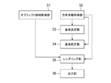
- control unit 11 of the information processing device 1 By executing the program stored in the storage unit 12, the control unit 11 according to the present embodiment functionally includes the object information acquisition unit 31 and the direction information acquisition unit 32, as illustrated in FIG. , A configuration including a reference determination unit 33, a reference setting unit 34, a rendering unit 35, and an output unit 36 is realized.
- the object information acquisition unit 31 acquires information on a virtual object to be displayed in the virtual space.
- the object information acquired by the object information acquisition unit 31 is provided from the application program side such as a game application, and includes information such as the shape and texture of one or more objects, the position and orientation of arrangement, and the like. Since the information of such an object and the process of acquiring the object are widely known, detailed description thereof is omitted here.
- the direction information acquisition unit 32 repeatedly acquires information on the line-of-sight direction of the user wearing the display device 2 at predetermined timings (for example, every 1/30 second).
- the direction information acquisition unit 31 uses information such as the posture of the display device 2 worn by the user based on a user's image taken by a camera (not shown) or output by a posture sensor included in the display device 2. It detects and acquires information on the direction of the user's head (direction of the head, direction of the front of the face).
- the direction information acquisition unit 32 may acquire information on the direction of the user's head (the direction in which the front of the face is facing) based on an image taken by a camera (not shown) provided in the display device 2.
- a widely known method such as an application of SLAM (Simultaneous Localization and Mapping) technology can be adopted.
- the direction of the user's head is expressed as follows. That is, let ⁇ be the angle of the user's face in the real space in the elevation direction (angle in the sagittal plane), ⁇ be the angle in the left-right direction (angle in the cross section), and ⁇ be the angle in the coronal plane. ..
- the direction of the user's head (direction in the world coordinate system) is represented by a set of these angles ( ⁇ , ⁇ , ⁇ ).
- the direction information acquisition unit 32 acquires the information of this set of angles as the information indicating the direction of the user's head.
- the direction information acquisition unit 32 in this example is the direction of the user's head in the real space when a predetermined initialization operation (for example, activation or calibration) is performed on the information processing device 1.
- a predetermined initialization operation for example, activation or calibration
- the amount of change in the angle from this real space reference direction to each direction, where the front direction in which the face faces) is the reference direction (called the real space reference direction) ( ⁇ , ⁇ , ⁇ ) (0, 0, 0). Detects the direction of the user's head with.
- the direction of the user's line of sight is expressed as ⁇ E for the angle from the real space reference direction to the elevation angle direction (angle in the sagittal plane) and ⁇ E for the angle in the left-right direction (angle in the cross section).
- ⁇ E for the angle from the real space reference direction to the elevation angle direction (angle in the sagittal plane)
- ⁇ E for the angle in the left-right direction (angle in the cross section).
- the direction information acquisition unit 32 is a user when the user performs a predetermined initialization operation such as starting the information processing device 1 or instructing the information processing device 1 to perform calibration.
- Information on the direction of the head is acquired.
- the direction information acquisition unit 32 sets the direction of the user's head (front direction in which the user's face faces) when the information indicating the direction of the line of sight is obtained as ( ⁇ H, ⁇ H, ⁇ H), and the information indicating the direction of the line of sight.
- ( ⁇ E, ⁇ E, ⁇ E) as ( ⁇ H + ⁇ E, ⁇ H + ⁇ E, ⁇ H).
- the direction information acquisition unit 32 may use the detected information on the direction of the user's head as it is as information on the user's line-of-sight direction.
- the information indicating the direction of the line of sight ( ⁇ E, ⁇ E, ⁇ E) is equal to the direction of the user's head (front direction in which the user's face faces) ( ⁇ H, ⁇ H, ⁇ H).
- the direction information acquisition unit 32 repeatedly acquires information indicating the direction of the user's head and information on the user's line-of-sight direction at predetermined timings (for example, once every 1/30 second) by such a method. Output.
- the reference determination unit 33 determines the reference direction (virtual space reference direction) in the user's virtual space. In the present embodiment, the reference determination unit 33 determines the virtual space reference direction of the user as follows.
- the reference determination unit 33 initially (at the time of activation, when the control unit 11 starts executing the program) acquires information on the direction of the user's head in the real space ( ⁇ H, ⁇ H, ⁇ H) acquired by the direction information acquisition unit 32. Is used to set the virtual space reference direction ( ⁇ 0, ⁇ 0, ⁇ 0).
- each component of the information representing the virtual space reference direction is an angle in the elevation angle direction (angle in a plane perpendicular to the floor surface of the virtual space) ⁇ and an angle in the left-right direction (parallel to the floor surface of the virtual space). (Angle in the plane) ⁇ and the rotation angle ⁇ around this axis with the direction of the line of sight as the rotation axis, respectively.
- the reference determination unit 33 initially acquires information on the direction of the user's head in the real space ( ⁇ H, ⁇ H, ⁇ H) or the line-of-sight direction ( ⁇ H, ⁇ H, ⁇ H) acquired by the direction information acquisition unit 32 at the time of activation.
- the reference determination unit 33 while the direction of the user's head (direction in front of the head) or the line-of-sight direction represented by the information acquired by the direction information acquisition unit 32 is a direction that satisfies a predetermined candidate determination condition.
- a candidate for the virtual space reference direction is determined based on the information on the line-of-sight direction acquired by the direction information acquisition unit 32.
- the reference determination unit 33 determines the candidate for the virtual space reference direction, but does not change the virtual space reference direction at that time.
- the information of the candidate determination flag initially set to off is used.
- the reference determination unit 33 includes the elevation direction component ⁇ H and the left-right direction component ⁇ H among the directions ( ⁇ H, ⁇ H, ⁇ H) of the user's head represented by the information acquired by the direction information acquisition unit 32, and the real space. Find the difference from the value of the corresponding component in the reference direction (0, 0, 0). Then, the reference determination unit 33 satisfies this candidate determination condition with the above candidate determination condition that the difference of the component having the largest value among the differences of each component exceeds a predetermined threshold value. Judge whether or not.
- the reference determination unit 33 determines that the candidate determination condition is satisfied.
- the reference determination unit 33 is a virtual space corresponding to the user's line-of-sight direction ( ⁇ E, ⁇ E, ⁇ E) when the user performs a predetermined candidate determination operation or action while it is determined that the candidate determination condition is satisfied. Is determined as a candidate for the virtual space reference direction.
- the predetermined candidate determination operation or action performed by the user here may be, for example, an operation of pressing a predetermined button of the operation device 3. Further, if the blinking sensor 4 is connected to the information processing device 1, the predetermined candidate determination operation or action performed by the user may be blinking. Further, the predetermined candidate determination operation or action performed by the user may be such that the line-of-sight direction is not changed for a predetermined time. Specifically, in order to detect that the user does not change the line-of-sight direction, it is detected that the maximum value of the amount of change in the line-of-sight direction of the user acquired during a predetermined time falls below a predetermined threshold value. That is, it may be detected that the person is staring at a predetermined range on the screen.
- the reference determination unit 33 determines the direction of the user's line of sight at that time.
- the reference setting unit 34 determines the direction and inclination ( ⁇ W, ⁇ W, ⁇ W, ⁇ W,) of the user's visual field in the virtual space.
- the angle of the user's face in the elevation angle direction (angle in the sagittal plane) in the virtual space is ⁇
- the angle in the left-right direction (angle in the cross section) is ⁇
- the plane in the viewing direction coronal plane.
- the angle (in the plane) is expressed as ⁇ .
- the reference setting unit 34 makes the information of the direction of the visual field stored by the reference determination unit 33 invalid, and returns the candidate determination flag to off to continue the process.
- the above setting conditions are (1) The user's line-of-sight direction or head direction is moving toward the reference direction (2) The user's line-of-sight direction or head direction is moving toward the reference direction, and blinking What has been done (3) It is determined in advance that the user has performed a predetermined setting operation or action.
- Each distance is determined by a method such as using the spherical cosine theorem.
- the reference setting unit 34 sets the setting conditions. (2) It may be assumed that the direction of the user's head is moving toward the reference direction and the user blinks. In this case, when the reference setting unit 34 determines that the direction of the user's head is moving toward the reference direction by the above method, the blink sensor 4 outputs a signal indicating that the blink sensor 4 has detected the blink. , It is assumed that the setting conditions are satisfied. When the setting condition is satisfied, the reference setting unit 34 sets the virtual space reference direction ( ⁇ 0, ⁇ 0, ⁇ 0) to the stored value ( ⁇ C, ⁇ C, ⁇ C).
- the reference setting unit 34 sets the field of view by, for example, setting the direction and inclination of the field of view by any of the above methods, and separately setting the angle of view of the field of view (for example, by following the instructions of the game application). Do.
- the rendering unit 35 renders and generates an image of an object included in the virtual three-dimensional space projected onto the user's field of view, which is set by the reference setting unit 34. Since this process is a general three-dimensional graphics process, detailed description thereof will be omitted here.
- the output unit 36 outputs an image of an object in the virtual three-dimensional space generated by the rendering unit 35 to the display device 2.
- the present embodiment basically includes the above configuration and operates as follows.
- the information processing device 1 executes a process of arranging and displaying an object in a virtual game space (virtual space) in a process of a game application or the like.
- the user's position (the position of the virtual camera for rendering) in the virtual space is shown as an example of the plan view and the side view in FIGS. 3 (a) and 3 (b), respectively.
- An example is a case where a texture of a 360-degree image is pasted on the inner surface of a spherical object P at the center.
- the information processing device 1 of the present embodiment is not limited to such an example, and can be applied to an example in which a plurality of virtual objects are arranged in a virtual three-dimensional space. ..
- the angle of the user's face in the elevation direction (angle in the sagittal plane) in the virtual three-dimensional space is ⁇
- the angle in the left-right direction (angle in the cross section) is ⁇
- the angle in the plane (in the coronal plane) of the field of view of the camera is expressed as ⁇ .
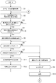
- the information processing device 1 performs the process shown in FIG. 4 to acquire information (information such as shape, position, texture, etc.) of objects arranged in the virtual space (S1).
- the information processing device 1 repeatedly acquires information on the direction of the user's head ( ⁇ H, ⁇ H, ⁇ H) and information on the line-of-sight direction ( ⁇ E, ⁇ E, ⁇ E) at predetermined timings (S2).
- the information processing apparatus 1 acquires such information, among the directions of the user's head ( ⁇ H, ⁇ H, ⁇ H), the elevation angle direction component ⁇ H and the left-right direction component ⁇ H and the reference direction (0, 0, 0) ) Is calculated from the value of the corresponding component. Then, the information processing apparatus 1 examines whether or not the difference of the component having the largest value among the obtained difference values of each component exceeds a predetermined threshold value (for example, 5 degrees) (S3). ). Here, if the difference between the above components exceeds a predetermined threshold value (S3: Yes), the information processing apparatus 1 further examines whether or not the user has performed a predetermined candidate determination operation or action (S4). ). Specifically, the predetermined candidate determination operation or action here is predetermined as an operation of pressing a predetermined button of the operation device 3.
- a predetermined threshold value for example, 5 degrees
- the information processing device 1 determines in the process S4 that the user has performed a predetermined candidate determination operation or action (S4: Yes), it corresponds to the information in the line-of-sight direction of the user ( ⁇ E, ⁇ E, ⁇ E) at that time.
- the direction of the virtual space that is, ( ⁇ E- ⁇ 0, ⁇ E- ⁇ 0, ⁇ E- ⁇ 0)
- ⁇ C, ⁇ C, ⁇ C the candidate determination flag is turned on.
- the information processing apparatus 1 determines whether or not the candidate determination flag is on (S6), and if it is on (process S6: Yes), determines whether or not the setting condition is satisfied (S7). ).
- the information processing device 1 separately determines the viewing angle of the field of view (by instructions from a game application, etc.).
- the information processing device 1 renders an image of an object in this visual field in this virtual three-dimensional space (S9), and displays the rendered image on the display device 2 (S10).
- the images presented to the left and right eyes are displayed by rendering the images of the objects in the field of view from the positions corresponding to the positions of the left and right eyes. You just have to get it.
- the information processing device 1 then returns to the process S2 to continue the process.
- the information processing apparatus 1 sets the direction of the visual field determined in the process S5 to the virtual space reference direction (S11), and sets the candidate determination flag.
- the process proceeds to process S8. That is, in this process S11, the virtual space reference direction ( ⁇ 0, ⁇ 0, ⁇ 0) of the user in the virtual three-dimensional space is set as the candidate ( ⁇ C, ⁇ C, ⁇ C) of the virtual space reference direction stored in the process S5. ..
- the in-plane angle of the field of view in this virtual space reference direction is always parallel to the floor surface, and the user's virtual space reference direction ( ⁇ 0) in the virtual three-dimensional space.
- ⁇ 0, ⁇ 0) may be set to (0, ⁇ C, 0) using only the information in the left-right direction out of the determined information in the direction of the visual field.
- the virtual space reference direction is set to ( ⁇ C, ⁇ C, 0) using the information of the elevation angle and the left-right direction. You may use some information such as, or you may set the virtual space reference direction to ( ⁇ C, ⁇ C, ⁇ C) by using all the information.
- the virtual space reference direction is then set to the direction ( ⁇ C, ⁇ C, ⁇ C) in which the user turned his / her line of sight in the past and performed a predetermined candidate determination operation or action. Therefore, after that, when the visual field is determined based on the line-of-sight direction, this virtual space reference direction is used, and the user uses the front of the head as the real space reference direction (generally, the front of the user).
- the side front side of the body
- the image in the field of view in the direction determined in the process S8 is rendered and presented.
- ⁇ the direction and inclination ( ⁇ , ⁇ , ⁇ ) of the user's visual field in the virtual space.
- process S3: No when the difference of the component having the largest value among the differences of the components in the process S3 does not exceed a predetermined threshold value (for example, 5 degrees) (process S3: No). ), And when it is not determined in the process S4 that the user has performed a predetermined candidate determination operation or action (process S4: No), the process proceeds to the process S6 and the process is continued.
- a predetermined threshold value for example, 5 degrees
- the information processing device 1 of the present embodiment of this example is connected to a display device 2 worn on the user's head and an operation device 3 operated by the user.
- the blink sensor 4 is not always necessary.
- a predetermined threshold value for example, 5 degrees
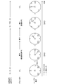
- the information processing device 1 subsequently obtains information on the user's line-of-sight direction ( ⁇ E, ⁇ E, ⁇ E) and information on the set virtual space reference direction (direction in which the character “SE” is drawn) ( ⁇ 0, Using ⁇ 0, ⁇ 0), the direction of the user's field of view in the virtual space is defined as ( ⁇ E- ⁇ 0, ⁇ E- ⁇ 0, ⁇ E- ⁇ 0), and objects within a predetermined angle of view range (field of view) in this direction.
- the image of is rendered and displayed on the display device 2.
- the user initially faces the direction in which the character "N” is drawn in the virtual space, but performs a predetermined candidate determination operation while looking at the direction in which the character "SE” is drawn.
- the virtual space is rotated around the user while the direction of the head is returned to the front side, and the direction in which the characters "SE" are drawn is the direction of the user. It is set to be in front.
- the information processing device 1 of the present embodiment of this example is connected to a display device 2 worn on the user's head, an operation device 3 operated by the user, and a blink sensor 4.
- the head is turned to the right (the direction in which ⁇ becomes larger) from the state in which the user initially faces a predetermined direction (the direction in which the character “N” is drawn). It is assumed that the direction in which the character “E” is drawn) is further directed to the right side, and the direction in which the character “SE” in FIG. 6 is drawn is directed (S31).
- a predetermined threshold value for example, 5 degrees
- the information processing device 1 receives information on the user's line-of-sight direction at that time (S32).
- the information processing device 1 subsequently obtains information on the user's line-of-sight direction ( ⁇ E, ⁇ E, ⁇ E) and information on the set virtual space reference direction (direction in which the character “SE” is drawn) ( ⁇ 0, ⁇ 0). , ⁇ 0), and the direction of the user's field of view in the virtual space is defined as ( ⁇ E- ⁇ 0, ⁇ E- ⁇ 0, ⁇ E- ⁇ 0), and the object within the range (field of view) of the predetermined angle of view in this direction.
- the image is rendered and displayed on the display device 2.
- the user initially faces the direction in which the character "N” is drawn in the virtual space, but performs a predetermined candidate determination operation while looking at the direction in which the character "SE” is drawn.
- the virtual space is rotated around the user while the blinking is performed, and the direction in which the characters "SE" are drawn is the direction of the user. It is set to be in front.
- the information processing device 1 of the present embodiment of this example is connected to a display device 2 worn on the user's head and an operation device 3 operated by the user.
- the blink sensor 4 is not always necessary.
- the predetermined button of the operation device 3 is pressed (held and held) as the candidate determination condition, and the setting condition is that the finger is released from the predetermined button of the operation device 3. And.
- the information processing device 1 moves the button.
- the information processing device 1 subsequently obtains information on the user's line-of-sight direction ( ⁇ E, ⁇ E, ⁇ E) and information on the set virtual space reference direction (direction in which the character “SE” is drawn) ( ⁇ 0, ⁇ 0). , ⁇ 0), and the direction of the user's field of view in the virtual space is defined as ( ⁇ E- ⁇ 0, ⁇ E- ⁇ 0, ⁇ E- ⁇ 0), and the object within the range (field of view) of the predetermined angle of view in this direction.
- the image is rendered and displayed on the display device 2.
- the information processing apparatus 1 is satisfied with the setting conditions at that time.
- this embodiment is not limited to this.
- the information processing device 1 uses the direction of the head in the real space at that time ( ⁇ M, ⁇ M, ⁇ M) and uses the virtual space reference direction as follows. May be set.
- an object in the direction represented by the determined virtual space reference direction is set in the direction of the visual field at that time. It will be drawn.
- the information processing device 1 is connected to the blinking sensor 4, and when the user presses a predetermined first button (a button set to instruct the rotation to the right) of the operation device 3, the information processing device 1 at that time is pressed.
- a predetermined first button a button set to instruct the rotation to the right
- a direction rotated by a predetermined angle ⁇ from the virtual space reference direction may be determined as a candidate for the virtual space reference direction.
- a predetermined second button a button set to instruct the leftward rotation of the operation device 3
- ⁇ a predetermined angle from the virtual space reference direction at that time to the left.
- the direction rotated by ⁇ (direction of ⁇ 0 ⁇ ) may be determined as a candidate for the virtual space reference direction.
- the information processing device 1 blinks the next time the user blinks after the candidate for the virtual space reference direction is set (when the blink sensor 4 outputs a signal indicating that the user blinks).
- the virtual space reference direction is set to the direction of the candidate of the determined virtual space reference direction.
- the rotation in the direction of the field of view is performed while the user is blinking.
- the direction of rotation when obtaining the candidate direction of the virtual space reference direction is not limited to the above-mentioned right direction or left direction, and may be upward or downward in the elevation angle direction depending on the setting of the button of the operation device 3. May be rotated.
- the present embodiment is not limited to this.
- the direction is determined to be rotated by a predetermined angle or more from the virtual space reference direction at that time.
- the direction rotated by the angle ⁇ of may be determined as a candidate for the virtual space reference direction.
- the virtual space reference direction may be set in the direction of the candidate of the determined virtual space reference direction.
- the operation of the operation device 3 is not required, so that the rotation in the visual field direction can be performed by a more intuitive method.
- the blink sensor 4 connected to the information processing device 1 of the present embodiment may be capable of detecting not only the blink but also the opening degree of the user's eyes. In this case, the blink sensor 4 repeatedly detects the information on the opening degree of the user's eyes at predetermined timings and outputs the information to the information processing device 1. Further, also at this time, when the user blinks, the blink sensor 4 shall output a signal indicating that the user has blinked to the information processing device 1.
- the information processing device 1 determines whether or not the opening degree of the user's eyes output by the blink sensor 4 falls below a predetermined threshold value when the candidate determination flag is on.
- the state in which the opening degree of the eyes falls below a predetermined threshold value is a so-called thin state. That is, as the threshold value here, it is assumed that a general human being is in a state where visual recognition is deteriorated.
- the setting condition for setting the virtual space reference direction is that the user has performed a predetermined setting operation, and the user's when the user performs the operation.
- the virtual space reference direction is set to ( ⁇ 0, ⁇ 0, ⁇ 0).
- ( ⁇ C + ⁇ M, ⁇ C + ⁇ M, ⁇ C + ⁇ M) may be set.
- the direction of the stored virtual space reference direction candidate is set to the direction of the user's line of sight when the above setting operation is performed. That is, the user performs a candidate determination operation or the like to determine a candidate in the virtual space reference direction while moving the head and arranging the line of sight in a desired direction, and then moves in another direction (called a setting direction). Perform the setting operation to set the virtual space reference direction with the line of sight arranged.
- the information processing apparatus 1 of this example rotates the virtual space around the position of the virtual user so that the direction represented by the candidate in the virtual space reference direction is positioned in the setting direction. This allows the user to rotate the virtual space in any direction.
- 1 Information processing device 2 Display device, 3 Operation device, 4 Blink sensor, 11 Control unit, 12 Storage unit, 13 Interface unit, 21 Video display element, 22 Optical element, 23 Line-of-sight detection unit, 31 Object information acquisition unit, 32 Direction information acquisition unit, 33 reference determination unit, 34 reference setting unit, 35 rendering unit, 36 output unit.
Landscapes
- Engineering & Computer Science (AREA)
- Theoretical Computer Science (AREA)
- Physics & Mathematics (AREA)
- General Physics & Mathematics (AREA)
- Computer Hardware Design (AREA)
- General Engineering & Computer Science (AREA)
- Human Computer Interaction (AREA)
- Computer Graphics (AREA)
- Software Systems (AREA)
- User Interface Of Digital Computer (AREA)
Priority Applications (1)
| Application Number | Priority Date | Filing Date | Title |
|---|---|---|---|
| JP2021520067A JPWO2020235191A1 (https=) | 2019-05-21 | 2020-03-12 |
Applications Claiming Priority (2)
| Application Number | Priority Date | Filing Date | Title |
|---|---|---|---|
| JP2019095495 | 2019-05-21 | ||
| JP2019-095495 | 2019-05-21 |
Publications (1)
| Publication Number | Publication Date |
|---|---|
| WO2020235191A1 true WO2020235191A1 (ja) | 2020-11-26 |
Family
ID=73458544
Family Applications (1)
| Application Number | Title | Priority Date | Filing Date |
|---|---|---|---|
| PCT/JP2020/010921 Ceased WO2020235191A1 (ja) | 2019-05-21 | 2020-03-12 | 情報処理装置、情報処理装置の制御方法、及びプログラム |
Country Status (2)
| Country | Link |
|---|---|
| JP (1) | JPWO2020235191A1 (https=) |
| WO (1) | WO2020235191A1 (https=) |
Cited By (1)
| Publication number | Priority date | Publication date | Assignee | Title |
|---|---|---|---|---|
| JP2024051366A (ja) * | 2022-09-30 | 2024-04-11 | 株式会社ジェイテクト | 頭方向情報の決定方法、音処理装置、および、決定プログラム |
Citations (5)
| Publication number | Priority date | Publication date | Assignee | Title |
|---|---|---|---|---|
| JPH1098798A (ja) * | 1996-09-20 | 1998-04-14 | Murata Mfg Co Ltd | 角度計測装置およびこれを搭載したヘッドマウントディスプレイ装置 |
| JP2012203128A (ja) * | 2011-03-24 | 2012-10-22 | Seiko Epson Corp | 頭部装着型表示装置および頭部装着型表示装置の制御方法 |
| WO2015145544A1 (ja) * | 2014-03-24 | 2015-10-01 | パイオニア株式会社 | 表示制御装置、制御方法、プログラム及び記憶媒体 |
| WO2016042862A1 (ja) * | 2014-09-19 | 2016-03-24 | ソニー株式会社 | 制御装置、制御方法およびプログラム |
| US20170061696A1 (en) * | 2015-08-31 | 2017-03-02 | Samsung Electronics Co., Ltd. | Virtual reality display apparatus and display method thereof |
-
2020
- 2020-03-12 WO PCT/JP2020/010921 patent/WO2020235191A1/ja not_active Ceased
- 2020-03-12 JP JP2021520067A patent/JPWO2020235191A1/ja active Pending
Patent Citations (5)
| Publication number | Priority date | Publication date | Assignee | Title |
|---|---|---|---|---|
| JPH1098798A (ja) * | 1996-09-20 | 1998-04-14 | Murata Mfg Co Ltd | 角度計測装置およびこれを搭載したヘッドマウントディスプレイ装置 |
| JP2012203128A (ja) * | 2011-03-24 | 2012-10-22 | Seiko Epson Corp | 頭部装着型表示装置および頭部装着型表示装置の制御方法 |
| WO2015145544A1 (ja) * | 2014-03-24 | 2015-10-01 | パイオニア株式会社 | 表示制御装置、制御方法、プログラム及び記憶媒体 |
| WO2016042862A1 (ja) * | 2014-09-19 | 2016-03-24 | ソニー株式会社 | 制御装置、制御方法およびプログラム |
| US20170061696A1 (en) * | 2015-08-31 | 2017-03-02 | Samsung Electronics Co., Ltd. | Virtual reality display apparatus and display method thereof |
Non-Patent Citations (1)
| Title |
|---|
| YOSHIKAZU ONUKI ET AL.: "Reorient the Gazed Scene Towards the Center : Novel Virtual Turning Using Head and Gaze Motions and Blink", 2019 IEEE CONFERENCE ON VIRTUAL REALITY AND 3D USER INTERFACES (VR)[ ONLINE, 23 March 2019 (2019-03-23), pages 1864 - 1871, XP033597429, Retrieved from the Internet <URL:http://ieeexplore.ieee.org/stamp/stamp.jsp?tp=&arnumber=8797722> DOI: 10.1109/VR.2019.8797722 * |
Cited By (1)
| Publication number | Priority date | Publication date | Assignee | Title |
|---|---|---|---|---|
| JP2024051366A (ja) * | 2022-09-30 | 2024-04-11 | 株式会社ジェイテクト | 頭方向情報の決定方法、音処理装置、および、決定プログラム |
Also Published As
| Publication number | Publication date |
|---|---|
| JPWO2020235191A1 (https=) | 2020-11-26 |
Similar Documents
| Publication | Publication Date | Title |
|---|---|---|
| US11032537B2 (en) | Movable display for viewing and interacting with computer generated environments | |
| US20180292908A1 (en) | Control device of head mounted display, operation method and operation program thereof, and image display system | |
| US20220291744A1 (en) | Display processing device, display processing method, and recording medium | |
| JPH0749744A (ja) | 頭部搭載型表示入力装置 | |
| US11609428B2 (en) | Information processing apparatus and information processing method | |
| JPWO2016013272A1 (ja) | 情報処理装置及び情報処理方法、並びに画像表示システム | |
| US11743447B2 (en) | Gaze tracking apparatus and systems | |
| JP2020131044A (ja) | キャリブレーションシステム、及び、瞳孔間のキャリブレーション方法 | |
| JP6500570B2 (ja) | 画像表示装置および画像表示方法 | |
| JP6964142B2 (ja) | 情報処理装置、情報処理方法、及びプログラム | |
| KR20230037054A (ko) | 사용자의 신체에 대한 디바이스의 디스플레이를 업데이트하기 위한 시스템들, 방법들, 및 그래픽 사용자 인터페이스들 | |
| JP2018195172A (ja) | 情報処理方法、情報処理プログラム及び情報処理装置 | |
| JP6212666B1 (ja) | 情報処理方法、プログラム、仮想空間配信システム及び装置 | |
| CN106598259A (zh) | 一种头戴式设备的输入方法、输入器和vr头戴设备 | |
| CN110275304A (zh) | 一种xr头显及调整xr头显中播放图像的视场的方法 | |
| WO2020235191A1 (ja) | 情報処理装置、情報処理装置の制御方法、及びプログラム | |
| JP6479835B2 (ja) | 入出力装置、入出力プログラム、および入出力方法 | |
| JP2018147458A (ja) | 情報処理方法、プログラム、仮想空間配信システム及び装置 | |
| US20250103195A1 (en) | Facilitating extended reality target selection by blending gaze and controller raycasting, and systems and methods of use thereof | |
| JP4267556B2 (ja) | 眼球制御装置、眼球制御方法および眼球制御プログラム | |
| JPH10334274A (ja) | 仮想現実方法及び装置並びに記憶媒体 | |
| Fang et al. | Enhancing human perception of direct gaze from a social robot through eye-head coordination | |
| JP2018125727A (ja) | 顔画像処理装置 | |
| WO2022059730A1 (ja) | 情報処理装置、情報処理方法およびプログラム | |
| US12443275B2 (en) | Eye tracking system and methods of using an eye tracking system |
Legal Events
| Date | Code | Title | Description |
|---|---|---|---|
| 121 | Ep: the epo has been informed by wipo that ep was designated in this application |
Ref document number: 20810027 Country of ref document: EP Kind code of ref document: A1 |
|
| ENP | Entry into the national phase |
Ref document number: 2021520067 Country of ref document: JP Kind code of ref document: A |
|
| NENP | Non-entry into the national phase |
Ref country code: DE |
|
| 122 | Ep: pct application non-entry in european phase |
Ref document number: 20810027 Country of ref document: EP Kind code of ref document: A1 |