WO2020230730A1 - Bending system and die transfer method - Google Patents
Bending system and die transfer method Download PDFInfo
- Publication number
- WO2020230730A1 WO2020230730A1 PCT/JP2020/018708 JP2020018708W WO2020230730A1 WO 2020230730 A1 WO2020230730 A1 WO 2020230730A1 JP 2020018708 W JP2020018708 W JP 2020018708W WO 2020230730 A1 WO2020230730 A1 WO 2020230730A1
- Authority
- WO
- WIPO (PCT)
- Prior art keywords
- mold
- holding member
- right direction
- die
- unit
- Prior art date
Links
Images


Classifications
-
- B—PERFORMING OPERATIONS; TRANSPORTING
- B21—MECHANICAL METAL-WORKING WITHOUT ESSENTIALLY REMOVING MATERIAL; PUNCHING METAL
- B21D—WORKING OR PROCESSING OF SHEET METAL OR METAL TUBES, RODS OR PROFILES WITHOUT ESSENTIALLY REMOVING MATERIAL; PUNCHING METAL
- B21D5/00—Bending sheet metal along straight lines, e.g. to form simple curves
- B21D5/02—Bending sheet metal along straight lines, e.g. to form simple curves on press brakes without making use of clamping means
- B21D5/0209—Tools therefor
- B21D5/0254—Tool exchanging
-
- B—PERFORMING OPERATIONS; TRANSPORTING
- B21—MECHANICAL METAL-WORKING WITHOUT ESSENTIALLY REMOVING MATERIAL; PUNCHING METAL
- B21D—WORKING OR PROCESSING OF SHEET METAL OR METAL TUBES, RODS OR PROFILES WITHOUT ESSENTIALLY REMOVING MATERIAL; PUNCHING METAL
- B21D37/00—Tools as parts of machines covered by this subclass
- B21D37/04—Movable or exchangeable mountings for tools
-
- B—PERFORMING OPERATIONS; TRANSPORTING
- B21—MECHANICAL METAL-WORKING WITHOUT ESSENTIALLY REMOVING MATERIAL; PUNCHING METAL
- B21D—WORKING OR PROCESSING OF SHEET METAL OR METAL TUBES, RODS OR PROFILES WITHOUT ESSENTIALLY REMOVING MATERIAL; PUNCHING METAL
- B21D37/00—Tools as parts of machines covered by this subclass
- B21D37/14—Particular arrangements for handling and holding in place complete dies
- B21D37/145—Die storage magazines
-
- B—PERFORMING OPERATIONS; TRANSPORTING
- B21—MECHANICAL METAL-WORKING WITHOUT ESSENTIALLY REMOVING MATERIAL; PUNCHING METAL
- B21D—WORKING OR PROCESSING OF SHEET METAL OR METAL TUBES, RODS OR PROFILES WITHOUT ESSENTIALLY REMOVING MATERIAL; PUNCHING METAL
- B21D5/00—Bending sheet metal along straight lines, e.g. to form simple curves
- B21D5/004—Bending sheet metal along straight lines, e.g. to form simple curves with program control
-
- B—PERFORMING OPERATIONS; TRANSPORTING
- B21—MECHANICAL METAL-WORKING WITHOUT ESSENTIALLY REMOVING MATERIAL; PUNCHING METAL
- B21D—WORKING OR PROCESSING OF SHEET METAL OR METAL TUBES, RODS OR PROFILES WITHOUT ESSENTIALLY REMOVING MATERIAL; PUNCHING METAL
- B21D5/00—Bending sheet metal along straight lines, e.g. to form simple curves
- B21D5/02—Bending sheet metal along straight lines, e.g. to form simple curves on press brakes without making use of clamping means
Definitions
- the present invention is a bending system for bending a plate-shaped workpiece using an automatically replaceable die, and a die for transferring a die along a press brake die holder or a selected stocker. Regarding the mold transfer method.
- Patent Document 1 proposes a bending processing system provided on the side of a press brake and provided with a mold storage device for storing a plurality of dies.
- the mold storage device has a plurality of stockers for holding a plurality of molds. Each stocker extends in the left-right direction. Any selected stocker is configured to be positioned at a replacement position for mold replacement (automatic replacement).
- the bending system is equipped with a die holder for a press brake and a die changing unit for changing a die for a stocker positioned at a changing position.
- the mold changing unit is provided on the back side of the press brake table so as to be movable in the left-right direction.
- the mold changing unit has a mold holding member for holding the mold.
- the mold holding member can be engaged with and detached from the locking hole of the mold.
- the bending system includes a servomotor as a left-right moving part that moves the mold changing unit in the left-right direction.
- Patent Document 2 proposes an upper mold holder that replaceably holds the upper mold of a press brake.
- Patent Document 3 proposes a die attachment / detachment / replacement method for a press brake and a die storage device.
- the present invention provides a bending system and a mold transfer method capable of transferring only a predetermined mold to be exchanged in the left-right direction by a mold exchange unit without performing post-processing on the side surface of the mold. The purpose.
- the bending system according to the embodiment of the present invention is a die storage device having a plurality of stockers arranged around a press brake and capable of holding a plurality of dies extending in the left-right direction, and a table of the press brake.
- a first mold changing unit that is provided on the back side or the front side so as to be movable in the left-right direction and replaces a mold for the mold holder of the press brake and a stocker selected from the plurality of stockers.
- a second mold exchange unit a left-right moving unit that moves the first mold exchange unit and the second mold exchange unit in the left-right direction, and the first mold exchange unit, the said. It includes a second mold changing unit and a control unit that controls the left-right moving unit.
- the first mold exchange unit can be engaged with and detached from the locking hole of the mold, can hold the mold, and moves in the left-right direction together with the first mold exchange unit. It has a mold holding member.
- the second mold exchange unit can be engaged with and detached from the locking hole of the mold, can hold the mold, and moves in the left-right direction together with the second mold exchange unit. It has a mold holding member.
- the second mold is held in a state of being locked to the left and right, and then the first mold exchange unit is moved to the left and right while the movement of the second mold exchange unit in the left-right direction is stopped.
- the first mold exchange unit, the second mold exchange unit, and the left-right moving unit are controlled so as to move in the direction.
- the mold transfer method uses a first mold exchange unit and a second mold exchange unit provided so as to be movable in the left-right direction on the back side or the front side of the table of the press brake. This is the mold transfer method that was used.
- the first mold to be replaced is adjacent to the replacement target.
- the first mold holding member of the first mold changing unit is locked in the locking hole of the first mold when the second mold is in contact with the first mold.
- the first mold is held by the mold holding member of 1, and the second mold holding member of the second mold changing unit is locked in the locking hole of the second mold.
- the second mold is held by the second mold holding member in the state of being in the state, and subsequently, the movement of the second mold exchange unit in the left-right direction is stopped. 1 is provided with moving the mold changing unit in the left-right direction.
- the position of the second mold does not shift.
- only the first mold to be replaced can be transferred in the left-right direction by the first and second mold replacement units without post-processing the side surface of the mold.
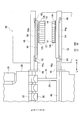
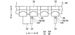
- FIG. 1 is a schematic front view showing a bending processing system according to an embodiment of the present invention.
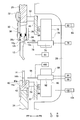
- FIG. 2 is a schematic front view showing the periphery of the stocker (upper stocker and lower stocker) positioned at the mold replacement position.
- FIG. 3 is an enlarged cross-sectional view taken along the line III-III in FIG.
- FIG. 4 is a control block diagram of the bending system according to the embodiment of the present invention.
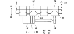
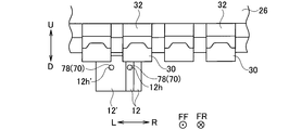
- FIG. 5A is a diagram showing a state in which a predetermined punch die is in contact with another adjacent punch die in a plurality of upper die holders.
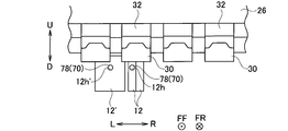
- FIG. 5B is a diagram showing how a predetermined punch die is transferred along a plurality of upper mold holders.
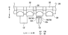
- FIG. 5C is a diagram showing how a predetermined punch die is transferred along a plurality of upper mold holders.
- FIG. 6A is a diagram showing a state in which a plurality of predetermined punch dies are in contact with other adjacent punch dies in the plurality of upper die holders.
- FIG. 6B is a diagram showing an operation for transferring a plurality of predetermined punch dies along a plurality of upper mold holders.
- FIG. 6C is a diagram showing an operation for transferring a plurality of predetermined punch dies along a plurality of upper mold holders.
- FIG. 6D is a diagram showing an operation for transferring a plurality of predetermined punch dies along a plurality of upper mold holders.
- FIG. 6E is a diagram showing an operation for transferring a plurality of predetermined punch dies along a plurality of upper mold holders.
- FIG. 7A is a diagram showing an operation for transferring a plurality of predetermined punch dies along a plurality of upper mold holders.
- FIG. 7B is a diagram showing an operation for transferring a plurality of predetermined punch dies along a plurality of upper mold holders.
- FIG. 7C is a diagram showing an operation for transferring a plurality of predetermined punch dies along a plurality of upper mold holders.
- FIGS. 1 to 7C An embodiment of the present invention will be described with reference to FIGS. 1 to 7C.
- the “left-right direction” is one of the horizontal directions, which is the width direction of the press brake 16 or the mold storage device 56.
- the “front-back direction” is the depth direction of the press brake 16 or the die storage device 56.
- Mold includes an upper mold and a lower mold.
- the “last mold” is the last mold when viewed from the mold transfer direction.
- the “first mold” is the first mold when viewed from the mold transfer method.
- FF indicates the forward direction
- FR indicates the backward direction
- L indicates the left direction
- R indicates the right direction
- U indicates the upward direction
- “D” indicates the downward direction.
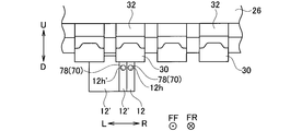
- FIGS. 5A to 7C of the locking holes of the plurality of punch dies, only the locking hole 12h in the locked state with the upper die holding member 78 is shown.
- the bending system 10 has a plate shape using a punch die 12 as an automatically replaceable upper die and a die die 14 as a lower die.
- This is a system for bending the work (sheet metal) W of the above.
- a round hole-shaped or elongated hole-shaped locking hole 12h is formed in the central portion of the punch die 12 in the width direction so as to penetrate in the front-rear direction.
- the shank portion 12s as the base portion of the punch die 12 is formed with a locking groove 12g for preventing the punch die 12 from falling (see FIG. 3).
- a round hole-shaped or elongated hole-shaped locking hole 14h is formed in the central portion of the die die 14 in the width direction so as to penetrate in the front-rear direction (see FIG. 3).
- the bending system 10 includes a press brake 16 that bends the work W in cooperation with the punch die 12 and the die die 14.
- the press brake 16 includes a main body frame 18.
- the main body frame 18 has a pair of side plates 20 that are separated from each other in the left-right direction and face each other, and a plurality of connecting members 22 that connect the pair of side plates 20 to each other.
- a lower table 24 extending in the left-right direction is provided at the lower part of the main body frame 18.
- An upper table 26 extending in the left-right direction is provided on the upper part of the main body frame 18 so as to be movable in the up-down direction.
- a hydraulic cylinder 28 is provided on the upper portion of each side plate 20 as a vertical moving portion for moving the upper table 26 in the vertical direction.
- the lower table 24 may be configured to be movable in the vertical direction.
- a servomotor (not shown) may be used instead of the hydraulic cylinder 28 as the vertical movement unit.
- Each upper mold holder 30 holds the punch die 12 detachably.
- Each upper mold holder 30 has, for example, a known configuration shown in Patent Document 2 and has a holder main body 34.
- a front clamp 36 that presses the shank portion 12s of the punch die 12 in the rearward direction is provided on the front side of each holder body 34 so as to be swingable.
- Each front clamp 36 has a claw portion 36c that can be locked in the locking groove 12g of the punch die 12 on the lower end side thereof.
- each holder body 34 On the rear side of each holder body 34, a rear clamp 38 that presses the shank portion 12s of the punch die 12 in a state where the front and back sides are inverted (in the front-rear direction) in the forward direction is provided so as to be swingable.
- Each rear clamp 38 has a claw portion 38c that can be locked in the locking groove 12g of the punch die 12 in a state where the front and back sides are inverted on the lower end side thereof.
- a lower mold holder 40 extending in the left-right direction is provided on the upper side of the lower table 24.
- the lower mold holder 40 holds the die mold 14 in a detachable manner.
- the lower mold holder 40 has, for example, the known configurations shown in Patent Documents 2 and 3, and a holder groove 40 g for inserting the shank portion 14s of the die mold 14 is formed along the left-right direction. There is.
- the lower mold holder 40 has a clamp 42 for fixing (pressing) the die mold 14.
- an upper connecting block 44 extending in the left-right direction is provided.
- a connecting groove 44g for inserting the shank portion 12s of the punch die 12 is formed along the left-right direction.
- the connecting grooves 44g of the upper connecting block 44 are arranged in series along the left-right direction in the gap between the holder main body 34 and the front clamp 36 in the plurality of upper mold holders 30.
- a lower connecting block 46 extending in the left-right direction is provided.
- a connecting groove 46g for inserting the shank portion 14s of the die mold 14 is formed along the left-right direction.
- the connecting groove 46g of the lower connecting block 46 is connected to the holder groove 40g of the lower mold holder 40.
- upper support beams 48 extending in the left-right direction are provided via a plurality of brackets 50 (only one is shown).
- the upper support beam 48 projects to the right of the upper connecting block 44.
- lower support beams 52 extending in the left-right direction are provided via a plurality of brackets 54 (only one is shown).
- the lower support beam 52 projects to the right of the lower connecting block 46.
- mold storage for storing a plurality of punch dies 12 and a plurality of die dies 14 on the left-right side of the press brake 16 (an example around the press brake 16).
- the device 56 is arranged.
- the mold storage device 56 has, for example, the same configuration as the known configurations shown in Patent Document 1 and Patent Document 3.
- the die storage device 56 has a plurality of (only one is shown) upper stockers 58 for holding the plurality of punch dies 12. Although only the upper stocker 58 positioned at the upper replacement position for replacing the punch die 12 is shown, the plurality of upper stockers 58 are arranged along the front-rear direction. Each upper stocker 58 extends in the left-right direction. Each upper stocker 58 is formed with a stocker groove 58g for inserting the shank portion 12s of the punch die 12 along the left-right direction. Each upper stocker 58 has a locking plate 60 that can be locked in the locking groove 12g of the punch die 12.
- the selected upper stocker 58 is configured to be positioned at the upper replacement position by an upper stocker moving mechanism (not shown).
- the upper stocker 58 positioned at the upper replacement position is supported by a pair of upper receiving members 62 provided on the right end side of the front surface of the upper support beam 48.
- the mold storage device 56 has a plurality of lower stockers 64 (only one is shown) for holding the plurality of die molds 14. Although only the lower stocker 64 positioned at the lower replacement position for replacing the die mold 14 is shown, the plurality of lower stockers 64 are arranged along the front-rear direction. Each lower stocker 64 extends in the left-right direction. A stocker groove 64g for inserting the shank portion 14s of the die mold 14 is formed in each lower stocker 64 along the left-right direction.
- the selected lower stocker 64 is configured to be positioned at the lower replacement position by a lower stocker moving mechanism (not shown).
- the lower stocker 64 positioned at the lower replacement position is supported by a pair of lower receiving members 66 provided on the right end side of the front surface of the lower support beam 52.
- an upper guide rail 68 extending in the left-right direction is provided on the back surface (rear surface) of the upper support beam 48.
- a pair of upper die changing units 70 for exchanging the punch die 12 with respect to the plurality of upper die holders 30 and the upper stocker 58 positioned at the upper changing position can move in the left-right direction. It is provided in.
- the pair of upper mold changing units 70 are provided on the back side of the upper table 26 so as to be movable in the left-right direction via the upper support beam 48 and the upper guide rail 68.
- Each upper die changing unit 70 transfers the punch die 12 between the upper die holder 30 and the upper stocker 58 positioned at the upper changing position.
- the pair of upper mold exchange units 70 includes a first upper mold exchange unit 70 and a second upper mold exchange unit 70.
- Each upper mold exchange unit 70 has the same configuration as the known configuration shown in Patent Document 1.
- Each upper mold changing unit 70 has an upper unit main body 72 and an upper support member 74.
- Each upper unit main body 72 is provided on the upper guide rail 68 so as to be movable in the left-right direction.
- Each upper support member 74 is provided on the upper unit main body 72 so as to be movable in the front-rear direction.
- Each upper support member 74 moves in the front-rear direction with respect to each upper unit main body 72 by driving an air cylinder 76 as a front-rear moving portion provided at an appropriate position of each upper unit main body 72.
- the upper support member 74 may be configured to be movable in the vertical direction with respect to the upper unit main body 72.
- Each upper die changing unit 70 has an upper die holding member 78 that is provided on each upper support member 74 so as to be movable in the front-rear direction and holds the punch die 12.
- the tip end side of each upper mold holding member 78 is formed in a round bar shape or a hook shape.
- Each upper die holding member 78 can be engaged with and detached from the locking hole 12h of the punch die 12.
- Each upper mold holding member 78 moves in the front-rear direction with respect to each upper support member 74 by driving an air cylinder 80 as another front-rear moving portion provided at an appropriate position of each upper support member 74.
- Servo motor 82 as a left-right moving part for moving each upper mold changing unit 70 in the left-right direction is provided at an appropriate position of each upper unit main body 72.
- Each servomotor 82 has an encoder 84 as a position detector that detects the position of each upper mold changing unit 70 (each upper mold holding member 78) in the left-right direction.
- Each servomotor 82 includes a first servomotor 82 and a second servomotor 82.
- Each encoder 84 includes a first encoder 84 and a second encoder 84.
- a lower guide rail 86 extending in the left-right direction is provided on the back surface of the lower support beam 52.
- a pair of lower mold replacement units 88 that replace the die mold 14 with respect to the plurality of lower mold holders 40 and the lower stocker 64 positioned at the lower replacement position can be moved in the left-right direction. It is provided in.
- the pair of lower mold changing units 88 are provided on the back side of the lower table 24 so as to be movable in the left-right direction via the lower support beam 52 and the lower guide rail 86.
- Each lower mold exchange unit 88 transfers the die mold 14 between the lower mold holder 40 and the lower stocker 64 positioned at the lower exchange position.
- the pair of lower mold exchange units 88 includes a first lower mold exchange unit 88 and a second lower mold exchange unit 88.
- Each lower mold exchange unit 88 has the same configuration as the known configuration shown in Patent Document 1.
- Each lower mold replacement unit 88 has a lower unit main body 90 and a lower support member 92.
- the lower unit main body 90 is provided on the lower guide rail 86 so as to be movable in the left-right direction.
- the lower support member 92 is provided on the lower unit main body 90 so as to be movable in the front-rear direction and the up-down direction.
- Each lower support member 92 moves in the front-rear direction with respect to each lower unit main body 90 by driving an air cylinder 94 as a front-rear moving portion provided at an appropriate position of each lower unit main body 90.
- Each lower support member 92 moves in the vertical direction with respect to each lower unit main body 90 by driving an air cylinder 96 as a vertical moving portion provided at an appropriate position of each lower unit main body 90.
- Each lower mold exchange unit 88 has a lower mold holding member 98 that is provided on each lower support member 92 so as to be movable in the front-rear direction and holds the die mold 14.
- the tip end side of each lower mold holding member 98 is formed in a round bar shape or a hook shape.
- Each lower mold holding member 98 can be engaged with and detached from the locking hole 14h of the die mold 14.
- Each lower mold holding member 98 moves in the front-rear direction with respect to each lower support member 92 by driving an air cylinder 100 as another front-rear moving portion provided at an appropriate position of each lower support member 92.
- Servo motors 102 are provided at appropriate positions on each lower unit main body 90 as left-right moving portions for moving each lower mold changing unit 88 in the left-right direction.
- Each servomotor 102 has an encoder 104 as a position detector that detects the position of each lower mold replacement unit 88 (each lower mold holding member 98) in the left-right direction.
- Each servomotor 102 includes a first servomotor 102 and a second servomotor 102.
- Each encoder 104 includes a first encoder 104 and a second encoder 104.
- the bending processing system 10 includes a control device (NC device) 106 as a control unit.
- the control device 106 controls the hydraulic cylinder 28 and the like based on the machining program, and controls the mold storage device 56 and the upper mold changing unit 70 and the like based on the mold changing program.
- the control device 106 is composed of a computer. Encoders 84, 104 and the like are connected to the control device 106.
- the control device 106 has a memory (not shown) for storing a machining program, a mold change program, and the like, and a CPU (not shown) for executing the machining program and the die change program.
- the control device 106 (See FIG. 5A), so that the upper die holding member 78 of the first upper die changing unit 70 holds the predetermined punch die 12 in a state of being locked in the locking hole 12h of the predetermined punch die 12. , Controls the first upper mold changing unit 70 and the first servomotor 82. Further, the control device 106 is in a state where the upper die holding member 78 of the second upper die changing unit 70 is locked in the locking hole 12h'of the other punch die 12', and the other punch die 12'.
- the second upper mold changing unit 70 and the second servomotor 82 are controlled so as to hold the above (see FIG. 5B). Subsequently, the control device 106 obtains the detection result from the first encoder 84 in a state where the movement of the second upper mold exchange unit 70 in the left-right direction is stopped, and the first upper mold exchange unit Each servomotor 82 is controlled so that the 70 moves in the left-right direction until it reaches the target position (see FIG. 5C).
- control device 106 can grasp that the predetermined punch dies 12 are in contact with other adjacent punch dies 12'in the plurality of upper die holders 30 based on the die change program. it can.
- the control device 106 when the control device 106 has a plurality of predetermined punch dies 12 (see FIG. 6A), the control device 106 has a plurality of predetermined upper die holding members 78 of the first upper die changing unit 70.
- the last punch die 12 of the punch dies 12 (the punch die 12 on the left side in FIGS. 6A to 6E) is held in the locking hole 12h so as to hold the last punch die 12.
- 1 Controls the upper mold changing unit 70 and the first servomotor 82. Further, the control device 106 is in a state where the upper die holding member 78 of the second upper die changing unit 70 is locked in the locking hole 12h'of the other punch die 12', and the other punch die 12'.
- the second upper mold changing unit 70 and the second servomotor 82 are controlled so as to hold the above (see FIG. 6B). Subsequently, the control device 106 obtains the detection result from the first encoder 84 in a state where the movement of the second upper mold exchange unit 70 in the left-right direction is stopped, and the first upper mold exchange unit Each servomotor 82 is controlled so that the 70 moves in the left-right direction by a predetermined amount (see FIG. 6C).
- the predetermined amount is a movement amount set in advance for separating the last punch die 12 from the other punch die 12'.
- the upper die holding member 78 of the first upper die changing unit 70 is the first punch die 12 of the plurality of predetermined punch dies (the right punch die in FIGS. 6A to 6E).
- the first upper die changing unit 70 and the first servomotor 82 are controlled so as to hold the leading punch die 12 in a state of being locked in the locking hole 12h of the die 12).
- the control device 106 holds the tail punching die 12 in a state where the upper die holding member 78 of the second upper die changing unit 70 is locked in the locking hole 12h of the tail punching die 12.
- the second upper mold changing unit 70 and the second servomotor 82 are controlled (see FIG. 6D).
- control device 106 obtains the detection results from the encoders 84 and moves the upper mold changing unit 70 in the left-right direction synchronously (or asynchronously) until the target position is reached.
- the servomotor 82 is controlled (see FIG. 6E).
- the plurality of predetermined punch dies 12 may have an intermediate punch die (not shown) between the first punch die 12 and the last punch die 12. In other words, the number of predetermined punch dies 12 may be three or more. Further, from the state shown in FIG. 6B, each servomotor 82 is controlled so that the first upper mold changing unit 70 moves in the left-right direction until it reaches the target position instead of moving in the left-right direction by a predetermined amount. You may.
- control device 106 is before the upper die holding member 78 of the first upper die changing unit 70 holds the last punch die 12 when there are a plurality of predetermined punch dies 12.
- control device 106 may control each upper mold changing unit 70 and each servomotor 82 as follows.
- the control device 106 holds the leading punch die 12 in a state where the upper die holding member 78 of the first upper die changing unit 70 is locked in the locking hole 12h of the leading punch die 12. As described above, the first upper mold changing unit 70 and the first servomotor 82 are controlled. Further, the control device 106 holds the last punch die 12 in a state where the upper die holding member 78 of the second upper die changing unit 70 is locked in the locking hole 12h of the last punch die 12. As described above, the second upper mold changing unit 70 and the second servomotor 82 are controlled (see FIG. 7A).
- the control device 106 obtains the detection result from the first encoder 84 in a state where the movement of the second upper mold exchange unit 70 in the left-right direction is stopped, and the first upper mold exchange unit Each servomotor 82 is controlled so that the 70 moves in the left-right direction by a predetermined amount (see FIG. 7B).
- the predetermined amount means a movement amount set in advance for separating the leading punch die 12 from the trailing punch die 12.
- the predetermined punch die 12 which is the replacement target (transfer target) is not an adjacent replacement target. Even when it is in contact with the punch die 12', each upper die changing unit 70 and each servomotor 82 are controlled in the same manner as described above. Further, in the control device 106, in the lower stocker 64 positioned at the upper and lower replacement positions of the lower mold holder 40, a predetermined die mold 14 which is a replacement target (transfer target) is adjacent to another die mold which is not a replacement target. Even when in contact with the mold (not shown), each lower mold replacement unit 88 and each servomotor 102 are controlled in the same manner as described above.
- the control when the punch die 12 is transferred from the upper die holder 30 to the upper stocker 58 positioned at the upper replacement position will be described.
- the control device 106 controls the servomotor 82 to move the upper die changing unit 70 in the left-right direction, and locks the punch die 12 in which the upper die holding member 78 is mounted on the upper die holder 30. Facing 12h.
- the control device 106 causes the upper die holding member 78 to hold the punch die 12 while engaging the upper die holding member 78 with the locking hole 12h of the punch die 12.
- the control device 106 controls the servomotor 82 to move the upper die changing unit 70 to the right, transfers the punch die 12 to the right, and separates the punch die 12 from the upper die holder 30.
- control device 106 controls the servomotor 82 to move the upper die changing unit 70 to the right, transfers the punch die 12 to the right, and attaches it to the upper stocker 58. After that, the control device 106 disengages the upper die holding member 78 from the locking hole 12h of the punch die 12 to release the holding state of the punch die 12 by the upper die holding member 78.
- the punch die 12 may be moved to the back side (rear) of the upper table 26 by the upper die changing unit 70.
- the die mold 14 When the die mold 14 is transferred between the lower mold holder 40 and the lower stocker 64 positioned at the lower replacement position, the same operation as described above is performed. As a result, the die mold 14 mounted on the lower mold holder 40 and the die mold 14 mounted on the lower stocker 64 can be automatically replaced.
- the lower mold exchange unit 88 may move the die mold 14 in the vertical direction.
- the mold transfer method according to the present embodiment is a method of transferring the molds 12 and 14 along the mold holders 30 and 40 or the stockers 58 and 64 positioned at the replacement positions.
- control device 106 controls each upper mold changing unit 70 and each servomotor 82 to operate as follows.
- the predetermined punch die 12 is held in a state where the upper die holding member 78 of the first upper die changing unit 70 is locked in the locking hole 12h of the predetermined punch die 12. Further, in a state where the upper die holding member 78 of the second upper die changing unit 70 is locked in the locking hole 12h'of the other punch die 12', the other punch die 12'is held ( See FIG. 5B). Subsequently, with the movement of the second upper mold changing unit 70 in the left-right direction stopped, the first upper mold changing unit 70 is set to the target position while acquiring the detection result from the first encoder 84. Move left and right until it reaches (see FIG. 5C).
- the other punch dies 12' are not dragged by the predetermined punch dies 12, so that the positions of the other punch dies 12'do not shift. Therefore, only the predetermined punch die 12 to be replaced can be transferred in the left-right direction by the upper die changing unit 70 without performing post-processing on the side surface of the punch die 12.
- control device 106 is used for each upper die changing unit 70 and each servomotor. By controlling 82, it operates as follows.
- the last punch die Hold the mold 12. Further, in a state where the upper die holding member 78 of the second upper die changing unit 70 is locked in the locking hole 12h'of the other punch die 12', the other punch die 12'is held ( See FIG. 6B). Subsequently, with the second upper mold changing unit 70 stopped moving in the left-right direction, the first upper mold changing unit 70 moves in the left-right direction by a predetermined amount (see FIG. 6C). As a result, the plurality of predetermined punch dies 12 can be separated from the other punch dies 12'.
- each upper mold changing unit 70 moves synchronously (or asynchronously) in the left-right direction until it reaches the target position (see FIG. 6E).
- the other punch dies 12' are not dragged by the plurality of predetermined punch dies 12, so that the positions of the other punch dies 12'do not shift. Therefore, without post-processing the side surface of the punch die 12, only the plurality of predetermined punch dies 12 to be replaced by the upper die changing unit 70 are moved in the left-right direction along the plurality of upper die holders 30. Can be transferred.
- control device 106 causes each upper die changing unit 70 and By controlling each servomotor 82, it may be operated as follows.
- the leading punch die 12 is held in a state where the upper die holding member 78 of the first upper die changing unit 70 is locked in the locking hole 12h of the leading punch die 12. Further, the upper die holding member 78 of the second upper die changing unit 70 holds the last punch die 12 in a state of being locked in the locking hole 12h of the last punch die 12 (see FIG. 7A). .. Subsequently, with the second upper mold changing unit 70 stopped moving in the left-right direction, the first upper mold changing unit 70 moves in the left-right direction by a predetermined amount. As a result, the leading punch die 12 can be separated from the trailing punch die 12.
- the transfer direction of the predetermined punch die 12 is shown as the right direction, and the upper die changing unit 70 on the right side is referred to as the first upper die changing unit 70, and the left side.
- the upper mold exchange unit 70 of the above is used as a second upper mold exchange unit 70.
- the transfer direction of the predetermined punch die 12 is to the left, the upper die changing unit 70 on the left side becomes the first upper die changing unit 70, and the upper die changing unit 70 on the right side becomes the second upper die.
- the replacement unit 70 will be used. That is, when the transfer direction of the predetermined punch die 12 is reversed, the first upper die exchange unit 70 and the second upper die exchange unit 70 are exchanged.
- a predetermined punch die 12 which is a replacement target (transfer target) is adjacent to another punch die which is not a replacement target. Even when it is in contact with 12', the control device 106 controls each upper type exchange unit 70 and each servomotor 82 to operate in the same manner as described above.
- the predetermined die mold 14 (or a plurality of predetermined die molds 14) to be replaced (transfer target) is not an adjacent replacement target.
- the control device 106 controls each lower die changing unit 88 and each servomotor 102 to operate in the same manner as described above.
- the other die dies are not dragged by the predetermined die dies 14 (or a plurality of predetermined die dies 14), so that the position of the other die dies does not shift.
- the predetermined die die 14 (or a plurality of predetermined die dies 14) is placed along the lower die holder 40 by the lower die changing unit 88. It can be transferred in the left-right direction.
- the bending processing system 10 can stably perform the operation related to the automatic replacement of the molds 12 and 14 while suppressing the increase in the manufacturing cost of the molds 12 and 14.
- the mold changing units 70 and 88 may be provided on the front side of the tables 26 and 24 so as to be movable in the left-right direction.
- the location of the mold storage device 56 may be other than the lateral side of the press brake 16 in the left-right direction as long as it is around the press brake 16.
- the present invention has, for example, the following configuration.
- the bending system is arranged around the press brake and has a die storage device having a plurality of stockers extending in the left-right direction and capable of holding a plurality of dies, and the press brake table on the back side or the front side.
- a first mold exchange unit and a second mold exchange that are provided so as to be movable in the left-right direction and exchange dies for the mold holder of the press brake and the stocker selected from the plurality of stockers.
- the unit, the left-right moving unit that moves the first mold exchange unit and the second mold exchange unit in the left-right direction, the first mold exchange unit, and the second mold exchange unit.
- a control unit that controls the left-right movement unit.
- the first mold exchange unit can be engaged with and detached from the locking hole of the mold, can hold the mold, and moves in the left-right direction together with the first mold exchange unit. It has a mold holding member.
- the second mold exchange unit can be engaged with and detached from the locking hole of the mold, can hold the mold, and moves in the left-right direction together with the second mold exchange unit. It has a mold holding member.
- the second mold is held in a state of being locked to, and subsequently, the first mold exchange unit moves to the left and right while the movement of the second mold exchange unit in the left-right direction is stopped.
- the first mold exchange unit, the second mold exchange unit, and the left-right moving unit are controlled so as to move in the direction.
- the second mold that is not the exchange target is not dragged by the first mold that is the exchange target, the position of the second mold does not shift.
- the first mold to be replaced can be transferred in the left-right direction by the first and second mold replacement units without post-processing the side surface of the mold. Therefore, it is possible to stably perform the operation related to the automatic replacement of the mold while suppressing the increase in the manufacturing cost of the mold.
- the control unit uses the first mold holding member as the second mold among the plurality of first dies.
- the last mold is held in a state of being locked in the locking hole of the last mold in contact, and the second mold holding member engages with the locking hole of the second mold.
- the second mold is held in the stopped state, and then the first mold exchange unit moves in the left-right direction while the movement of the second mold exchange unit in the left-right direction is stopped.
- the first mold holding member holds the first mold in a state where the first mold holding member is locked in the locking hole of the first mold among the plurality of first molds.
- the second mold holding member holds the last mold in a state of being locked in the locking hole of the last mold, and subsequently, the first mold exchange unit and the first mold are replaced.
- the first mold exchange unit, the second mold exchange unit, and the left-right movement unit may be controlled so that the mold exchange unit 2 moves in the left-right direction.
- the first mold holding member is placed in the locking hole of the leading mold before the first mold holding member holds the last mold.
- the leading mold is held in a locked state
- the trailing mold is held in a state where the second mold holding member is locked in the locking hole of the trailing mold, and then Then, while the movement of the second mold exchange unit in the left-right direction is stopped, the first mold exchange unit moves in the left-right direction by a predetermined amount.
- the unit, the second mold changing unit, and the left-right moving unit may be controlled.
- a first mold exchange unit and a second mold exchange unit provided so as to be movable in the left-right direction on the back side or the front side of the press brake table are used.
- the first mold to be replaced is adjacent to the replacement target.
- the first mold holding member of the first mold changing unit is locked in the locking hole of the first mold when the second mold is in contact with the first mold.
- the first mold is held by the mold holding member of 1
- the second mold holding member of the second mold changing unit is locked in the locking hole of the second mold.
- the second mold is held by the second mold holding member in the state of being in the state, and subsequently, the movement of the second mold exchange unit in the left-right direction is stopped.
- 1 is provided with moving the mold changing unit in the left-right direction.
- the second mold that is not the exchange target is not dragged by the first mold that is the exchange target, the position of the second mold does not shift.
- the first mold to be replaced can be transferred in the left-right direction by the first and second mold replacement units without post-processing the side surface of the mold. Therefore, it is possible to stably perform the operation related to the automatic replacement of the mold while suppressing the increase in the manufacturing cost of the mold.
- the first mold holding member is in contact with the second mold among the plurality of first molds.
- the last mold is held by the first mold holding member in a state of being locked in the locking hole of the last mold, and the second mold holding member is held by the second mold.
- the second mold is held by the second mold holding member in a state of being locked in the locking hole of the above, and subsequently, the movement of the second mold exchange unit in the left-right direction is performed.
- the first mold changing unit is moved in the left-right direction by a predetermined amount, and then the first mold holding member is moved to the head of the plurality of first molds.
- the first mold holding member holds the first mold in a state of being locked in the locking hole of the mold, and the second mold holding member is engaged with the last mold.
- the last mold is held by the second mold holding member in a state of being locked to the stop hole, and subsequently, the first mold exchange unit and the second mold exchange unit are held. It may be provided with the movement in the left-right direction.
- the first mold holding member is locked in the locking hole of the leading mold before the last mold is held by the first mold holding member.
- the first mold holding member holds the leading mold
- the second mold holding member is locked in the locking hole of the last mold.
- the first mold exchange unit is held in a state where the last mold is held by the mold holding member of No. 1 and subsequently, the movement of the second mold exchange unit in the left-right direction is stopped. It may be provided that it moves by a predetermined amount in the left-right direction.
Abstract
A first die holding member (78) of a first die exchanging unit (70) holds a first die (12), which is to be exchanged, in a state of being locked in a locking hole (12h) of the first die (12). A second die holding member (78) of a second die exchanging unit (70) holds a second die (12'), which is not to be exchanged, in a state of being locked in a locking hole (12h') of the second die (12'). Then, the first die exchanging unit (70) moves in a left-right direction, with movement of the second die exchanging unit (70) in the left-right direction stopped.
Description
本発明は、自動交換可能な金型を用いて板状のワークに対して曲げ加工を行うための曲げ加工システム、及びプレスブレーキの金型ホルダ又は選択したストッカに沿って金型を移送する金型移送方法に関する。
The present invention is a bending system for bending a plate-shaped workpiece using an automatically replaceable die, and a die for transferring a die along a press brake die holder or a selected stocker. Regarding the mold transfer method.
特許文献1は、プレスブレーキの側方に配置されかつ複数の金型を収納する金型収納装置を備えた曲げ加工システムを提案している。金型収納装置は、複数の金型を保持する複数のストッカを有する。各ストッカは、左右方向に延びている。選択した任意のストッカは、金型の交換(自動交換)を行うための交換位置に位置決め可能に構成されている。
Patent Document 1 proposes a bending processing system provided on the side of a press brake and provided with a mold storage device for storing a plurality of dies. The mold storage device has a plurality of stockers for holding a plurality of molds. Each stocker extends in the left-right direction. Any selected stocker is configured to be positioned at a replacement position for mold replacement (automatic replacement).
上記曲げ加工システムは、プレスブレーキの金型ホルダ及び交換位置に位置決めされたストッカに対して金型の交換を行う金型交換ユニットを備えている。金型交換ユニットは、プレスブレーキのテーブルの背面側に左右方向へ移動可能に設けられている。金型交換ユニットは、金型を保持する金型保持部材を有している。金型保持部材は、金型の係止穴に係脱可能である。曲げ加工システムは、金型交換ユニットを左右方向へ移動させる左右移動部としてのサーボモータを備えている。
The bending system is equipped with a die holder for a press brake and a die changing unit for changing a die for a stocker positioned at a changing position. The mold changing unit is provided on the back side of the press brake table so as to be movable in the left-right direction. The mold changing unit has a mold holding member for holding the mold. The mold holding member can be engaged with and detached from the locking hole of the mold. The bending system includes a servomotor as a left-right moving part that moves the mold changing unit in the left-right direction.
特許文献2は、プレスブレーキの上型を交換可能に保持する上型ホルダを提案している。特許文献3は、プレスブレーキの金型着脱交換方法及び金型収納装置を提案している。
Patent Document 2 proposes an upper mold holder that replaceably holds the upper mold of a press brake. Patent Document 3 proposes a die attachment / detachment / replacement method for a press brake and a die storage device.
ところで、金型ホルダ又は金型ストッカに保持された金型の側面には、油等が付着することが多い。交換対象(移送対象)である所定の金型が隣接する他の金型と接触している場合に、所定の金型と他の金型とが油等によって結合することがある。この状態で、金型交換ユニットによって所定の金型を左右方向へ移送しようとすると、他の金型が所定の金型に引きずられて、他の金型の位置ずれが生じることがある。その結果、曲げ加工システムが他の金型の配置位置を把握できなくなり、金型の移送動作を含む、金型の自動交換に関する動作を安定的に行うことができなくなることがある。他の金型の位置ずれの要因になる、隣接する金型同士の結合を防止するために、金型の側面に後加工として逃げ加工又はテーパ加工を施すと、金型の製造コスト(加工コスト)が増大する。
By the way, oil or the like often adheres to the side surface of the mold held by the mold holder or the mold stocker. When a predetermined mold to be replaced (transfer target) is in contact with another adjacent mold, the predetermined mold and the other mold may be bonded by oil or the like. In this state, if an attempt is made to transfer a predetermined mold in the left-right direction by the mold exchange unit, the other mold may be dragged by the predetermined mold and the position of the other mold may be displaced. As a result, the bending system may not be able to grasp the placement position of other molds, and may not be able to stably perform operations related to automatic mold replacement, including mold transfer operations. If relief processing or taper processing is applied to the side surface of the mold as post-processing in order to prevent bonding between adjacent molds, which causes misalignment of other molds, the manufacturing cost of the mold (processing cost) ) Increases.
つまり、金型の製造コストの増大を抑えつつ、曲げ加工システムによって金型の自動交換に関する動作を安定的に行うことが容易でないという問題がある。
That is, there is a problem that it is not easy to stably perform the operation related to the automatic replacement of the mold by the bending processing system while suppressing the increase in the manufacturing cost of the mold.
本発明は、金型の側面に後加工を施すことなく、金型交換ユニットによって交換対象である所定の金型のみを左右方向へ移送できる、曲げ加工システム及び金型移送方法を提供することを目的とする。
The present invention provides a bending system and a mold transfer method capable of transferring only a predetermined mold to be exchanged in the left-right direction by a mold exchange unit without performing post-processing on the side surface of the mold. The purpose.
本発明の実施態様に係る曲げ加工システムは、プレスブレーキの周辺に配置され、左右方向に延びて複数の金型を保持可能な複数のストッカを有する金型収納装置と、前記プレスブレーキのテーブルの背面側又は正面側に前記左右方向へ移動可能に設けられ、前記プレスブレーキの金型ホルダ及び前記複数のストッカのうちの選択したストッカに対して金型の交換を行う第1の金型交換ユニット及び第2の金型交換ユニットと、前記第1の金型交換ユニット及び前記第2の金型交換ユニットをそれぞれ前記左右方向へ移動させる左右移動部と、前記第1の金型交換ユニット、前記第2の金型交換ユニット、及び前記左右移動部を制御する制御部とを備える。前記第1の金型交換ユニットは、金型の係止穴に係脱可能であり、前記金型を保持可能であり、前記第1の金型交換ユニットと共に前記左右方向へ移動する第1の金型保持部材を有する。前記第2の金型交換ユニットは、金型の係止穴に係脱可能であり、前記金型を保持可能であり、前記第2の金型交換ユニットと共に前記左右方向へ移動する第2の金型保持部材を有する。前記制御部は、前記金型ホルダ又は前記選択したストッカにおいて、交換対象である第1の金型が隣接する交換対象でない第2の金型と接触している場合に、前記第1の金型保持部材が前記第1の金型の係止穴に係止した状態で前記第1の金型を保持し、かつ、前記第2の金型保持部材が前記第2の金型の係止穴に係止した状態で前記第2の金型を保持し、続いて、前記第2の金型交換ユニットの前記左右方向の移動を停止した状態で、前記第1の金型交換ユニットが前記左右方向へ移動するように、前記第1の金型交換ユニット、前記第2の金型交換ユニット、及び前記左右移動部を制御する。
The bending system according to the embodiment of the present invention is a die storage device having a plurality of stockers arranged around a press brake and capable of holding a plurality of dies extending in the left-right direction, and a table of the press brake. A first mold changing unit that is provided on the back side or the front side so as to be movable in the left-right direction and replaces a mold for the mold holder of the press brake and a stocker selected from the plurality of stockers. And a second mold exchange unit, a left-right moving unit that moves the first mold exchange unit and the second mold exchange unit in the left-right direction, and the first mold exchange unit, the said. It includes a second mold changing unit and a control unit that controls the left-right moving unit. The first mold exchange unit can be engaged with and detached from the locking hole of the mold, can hold the mold, and moves in the left-right direction together with the first mold exchange unit. It has a mold holding member. The second mold exchange unit can be engaged with and detached from the locking hole of the mold, can hold the mold, and moves in the left-right direction together with the second mold exchange unit. It has a mold holding member. When the first mold to be replaced is in contact with an adjacent second mold that is not to be replaced in the mold holder or the selected stocker, the control unit performs the first mold. The first mold is held in a state where the holding member is locked in the locking hole of the first mold, and the second mold holding member is the locking hole of the second mold. The second mold is held in a state of being locked to the left and right, and then the first mold exchange unit is moved to the left and right while the movement of the second mold exchange unit in the left-right direction is stopped. The first mold exchange unit, the second mold exchange unit, and the left-right moving unit are controlled so as to move in the direction.
本発明の実施態様に係る金型移送方法は、プレスブレーキのテーブルの背面側又は正面側に左右方向へ移動可能に設けられた第1の金型交換ユニット及び第2の金型交換ユニットを用いた金型移送方法である。前記金型移送方法は、前記プレスブレーキの金型ホルダにおいて、又は前記プレスブレーキの周辺に配置された金型収納装置における選択したストッカにおいて、交換対象である第1の金型が隣接する交換対象でない第2の金型と接触している場合に、前記第1の金型交換ユニットの第1の金型保持部材を前記第1の金型の係止穴に係止させた状態で前記第1の金型保持部材により前記第1の金型を保持し、かつ、前記第2の金型交換ユニットの第2の金型保持部材を前記第2の金型の係止穴に係止させた状態で前記第2の金型保持部材により前記第2の金型を保持することと、続いて、前記第2の金型交換ユニットの前記左右方向の移動を停止させた状態で、前記第1の金型交換ユニットを前記左右方向へ移動させることとを備える。
The mold transfer method according to the embodiment of the present invention uses a first mold exchange unit and a second mold exchange unit provided so as to be movable in the left-right direction on the back side or the front side of the table of the press brake. This is the mold transfer method that was used. In the mold transfer method, in the mold holder of the press brake or in the selected stocker in the mold storage device arranged around the press brake, the first mold to be replaced is adjacent to the replacement target. When the first mold holding member of the first mold changing unit is locked in the locking hole of the first mold when the second mold is in contact with the first mold. The first mold is held by the mold holding member of 1, and the second mold holding member of the second mold changing unit is locked in the locking hole of the second mold. The second mold is held by the second mold holding member in the state of being in the state, and subsequently, the movement of the second mold exchange unit in the left-right direction is stopped. 1 is provided with moving the mold changing unit in the left-right direction.
上記構成によれば、交換対象でない第2の金型が交換対象である第1の金型に引きずられないため、第2の金型の位置ずれが生じない。これにより、金型の側面に後加工を施すことなく、第1及び第2の金型交換ユニットによって交換対象である第1の金型のみを左右方向へ移送することができる。
According to the above configuration, since the second mold that is not the exchange target is not dragged by the first mold that is the exchange target, the position of the second mold does not shift. As a result, only the first mold to be replaced can be transferred in the left-right direction by the first and second mold replacement units without post-processing the side surface of the mold.
よって、金型の製造コストの増大を抑えつつ、金型の自動交換に関する動作を安定的に行うことができる。
Therefore, it is possible to stably perform operations related to automatic mold replacement while suppressing an increase in mold manufacturing cost.
本発明の実施形態について、図1から図7Cを参照して説明する。
An embodiment of the present invention will be described with reference to FIGS. 1 to 7C.
なお、「左右方向」は、水平方向の1つであって、プレスブレーキ16又は金型収納装置56の幅方向である。「前後方向」は、プレスブレーキ16又は金型収納装置56の奥行方向である。「金型」は、上部金型及び下部金型を含む。「末尾の金型」は、金型の移送方向から見て末尾の金型である。「先頭の金型」は、金型の移送方法から見て先頭の金型である。図面中、「FF」は前方向、「FR」は後方向、「L」は左方向、「R」は右方向、「U」は上方向、「D」は下方向を示す。説明の便宜上、図5Aから図7Cにおいては、複数のパンチ金型の係止穴のうち、上部金型保持部材78と係止状態にある係止穴12hのみを図示している。
The "left-right direction" is one of the horizontal directions, which is the width direction of the press brake 16 or the mold storage device 56. The "front-back direction" is the depth direction of the press brake 16 or the die storage device 56. "Mold" includes an upper mold and a lower mold. The "last mold" is the last mold when viewed from the mold transfer direction. The "first mold" is the first mold when viewed from the mold transfer method. In the drawing, "FF" indicates the forward direction, "FR" indicates the backward direction, "L" indicates the left direction, "R" indicates the right direction, "U" indicates the upward direction, and "D" indicates the downward direction. For convenience of explanation, in FIGS. 5A to 7C, of the locking holes of the plurality of punch dies, only the locking hole 12h in the locked state with the upper die holding member 78 is shown.
図1から図3に示すように、本実施形態に係る曲げ加工システム10は、自動交換可能な上部金型としてのパンチ金型12及び下部金型としてのダイ金型14を用いて、板状のワーク(板金)Wに対して曲げ加工を行うためのシステムである。パンチ金型12の幅方向の中央部には、丸穴形状又は長穴形状の係止穴12hが前後方向に貫通して形成されている。パンチ金型12の基部としてのシャンク部12sには、パンチ金型12の落下防止用の係止溝12gが形成されている(図3参照)。ダイ金型14の幅方向の中央部には、丸穴形状又は長穴形状の係止穴14hが前後方向に貫通して形成されている(図3参照)。
As shown in FIGS. 1 to 3, the bending system 10 according to the present embodiment has a plate shape using a punch die 12 as an automatically replaceable upper die and a die die 14 as a lower die. This is a system for bending the work (sheet metal) W of the above. A round hole-shaped or elongated hole-shaped locking hole 12h is formed in the central portion of the punch die 12 in the width direction so as to penetrate in the front-rear direction. The shank portion 12s as the base portion of the punch die 12 is formed with a locking groove 12g for preventing the punch die 12 from falling (see FIG. 3). A round hole-shaped or elongated hole-shaped locking hole 14h is formed in the central portion of the die die 14 in the width direction so as to penetrate in the front-rear direction (see FIG. 3).
曲げ加工システム10は、パンチ金型12とダイ金型14との協働によりワークWに対して曲げ加工を行うプレスブレーキ16を備えている。
The bending system 10 includes a press brake 16 that bends the work W in cooperation with the punch die 12 and the die die 14.
プレスブレーキ16の構成について具体的に説明する。プレスブレーキ16は、本体フレーム18を備えている。本体フレーム18は、左右方向に離隔して対向した一対のサイドプレート20と、一対のサイドプレート20を互いに連結する複数の連結部材22とを有している。本体フレーム18の下部には、左右方向に延びた下部テーブル24が設けられている。本体フレーム18の上部には、左右方向に延びた上部テーブル26が上下方向へ移動可能に設けられている。各サイドプレート20の上部には、上部テーブル26を上下方向へ移動させる上下移動部として油圧シリンダ28が設けられている。なお、上部テーブル26を上下方向へ移動可能に構成する代わりに、下部テーブル24を上下方向へ移動可能に構成してもよい。上下移動部として油圧シリンダ28の代わりに、サーボモータ(図示省略)を用いてもよい。
The configuration of the press brake 16 will be specifically described. The press brake 16 includes a main body frame 18. The main body frame 18 has a pair of side plates 20 that are separated from each other in the left-right direction and face each other, and a plurality of connecting members 22 that connect the pair of side plates 20 to each other. A lower table 24 extending in the left-right direction is provided at the lower part of the main body frame 18. An upper table 26 extending in the left-right direction is provided on the upper part of the main body frame 18 so as to be movable in the up-down direction. A hydraulic cylinder 28 is provided on the upper portion of each side plate 20 as a vertical moving portion for moving the upper table 26 in the vertical direction. Instead of configuring the upper table 26 so as to be movable in the vertical direction, the lower table 24 may be configured to be movable in the vertical direction. A servomotor (not shown) may be used instead of the hydraulic cylinder 28 as the vertical movement unit.
上部テーブル26の下端部には、複数の上部金型ホルダ30が固定金具(締め金)32を介して左右方向に間隔を置いて設けられている。各上部金型ホルダ30は、パンチ金型12を着脱可能に保持する。各上部金型ホルダ30は、例えば、特許文献2に示す公知の構成からなり、ホルダ本体34を有している。各ホルダ本体34の前側には、パンチ金型12のシャンク部12sを後方向側に押圧するフロントクランプ36が揺動可能に設けられている。各フロントクランプ36は、その下端側に、パンチ金型12の係止溝12gに係止可能な爪部36cを有している。各ホルダ本体34の後側には、(前後方向において)表裏を反転させた状態のパンチ金型12のシャンク部12sを前方向に押圧するリアクランプ38が揺動可能に設けられている。各リアクランプ38は、その下端側に、表裏を反転させた状態のパンチ金型12の係止溝12gに係止可能な爪部38cを有している。
At the lower end of the upper table 26, a plurality of upper mold holders 30 are provided at intervals in the left-right direction via fixing brackets (clamps) 32. Each upper die holder 30 holds the punch die 12 detachably. Each upper mold holder 30 has, for example, a known configuration shown in Patent Document 2 and has a holder main body 34. A front clamp 36 that presses the shank portion 12s of the punch die 12 in the rearward direction is provided on the front side of each holder body 34 so as to be swingable. Each front clamp 36 has a claw portion 36c that can be locked in the locking groove 12g of the punch die 12 on the lower end side thereof. On the rear side of each holder body 34, a rear clamp 38 that presses the shank portion 12s of the punch die 12 in a state where the front and back sides are inverted (in the front-rear direction) in the forward direction is provided so as to be swingable. Each rear clamp 38 has a claw portion 38c that can be locked in the locking groove 12g of the punch die 12 in a state where the front and back sides are inverted on the lower end side thereof.
下部テーブル24の上側には、左右方向に延びている下部金型ホルダ40が設けられている。下部金型ホルダ40は、ダイ金型14を着脱可能に保持する。下部金型ホルダ40には、例えば、特許文献2及び特許文献3に示す公知の構成からなり、ダイ金型14のシャンク部14sを挿入させるためのホルダ溝40gが左右方向に沿って形成されている。下部金型ホルダ40は、ダイ金型14を固定(押圧)するクランプ42を有している。
A lower mold holder 40 extending in the left-right direction is provided on the upper side of the lower table 24. The lower mold holder 40 holds the die mold 14 in a detachable manner. The lower mold holder 40 has, for example, the known configurations shown in Patent Documents 2 and 3, and a holder groove 40 g for inserting the shank portion 14s of the die mold 14 is formed along the left-right direction. There is. The lower mold holder 40 has a clamp 42 for fixing (pressing) the die mold 14.
上部テーブル26の右側部には、左右方向に延びた上部繋ぎブロック44が設けられている。上部繋ぎブロック44には、パンチ金型12のシャンク部12sを挿入させるための繋ぎ溝44gが左右方向に沿って形成されている。上部繋ぎブロック44の繋ぎ溝44gは、複数の上部金型ホルダ30におけるホルダ本体34とフロントクランプ36との間隙に左右方向に沿って直列に配置されている。
On the right side of the upper table 26, an upper connecting block 44 extending in the left-right direction is provided. In the upper connecting block 44, a connecting groove 44g for inserting the shank portion 12s of the punch die 12 is formed along the left-right direction. The connecting grooves 44g of the upper connecting block 44 are arranged in series along the left-right direction in the gap between the holder main body 34 and the front clamp 36 in the plurality of upper mold holders 30.
下部テーブル24の右側部には、左右方向に延びた下部繋ぎブロック46が設けられている。下部繋ぎブロック46には、ダイ金型14のシャンク部14sを挿入させるための繋ぎ溝46gが左右方向に沿って形成されている。下部繋ぎブロック46の繋ぎ溝46gは、下部金型ホルダ40のホルダ溝40gに接続されている。
On the right side of the lower table 24, a lower connecting block 46 extending in the left-right direction is provided. In the lower connecting block 46, a connecting groove 46g for inserting the shank portion 14s of the die mold 14 is formed along the left-right direction. The connecting groove 46g of the lower connecting block 46 is connected to the holder groove 40g of the lower mold holder 40.
上部テーブル26の背面側(後側)には、左右方向に延びた上部支持ビーム48が複数(1つのみ図示)のブラケット50を介して設けられている。上部支持ビーム48は、上部繋ぎブロック44よりも右方向に突出している。下部テーブル24の背面側には、左右方向に延びた下部支持ビーム52が複数(1つのみ図示)のブラケット54を介して設けられている。下部支持ビーム52は、下部繋ぎブロック46よりも右方向に突出している。
On the back side (rear side) of the upper table 26, upper support beams 48 extending in the left-right direction are provided via a plurality of brackets 50 (only one is shown). The upper support beam 48 projects to the right of the upper connecting block 44. On the back side of the lower table 24, lower support beams 52 extending in the left-right direction are provided via a plurality of brackets 54 (only one is shown). The lower support beam 52 projects to the right of the lower connecting block 46.
図1及び図2に示すように、プレスブレーキ16の左右方向の側方(プレスブレーキ16の周辺の一例)には、複数のパンチ金型12及び複数のダイ金型14を収納する金型収納装置56が配置されている。金型収納装置56は、例えば、特許文献1及び特許文献3に示す公知の構成と同様の構成からなる。
As shown in FIGS. 1 and 2, mold storage for storing a plurality of punch dies 12 and a plurality of die dies 14 on the left-right side of the press brake 16 (an example around the press brake 16). The device 56 is arranged. The mold storage device 56 has, for example, the same configuration as the known configurations shown in Patent Document 1 and Patent Document 3.
金型収納装置56の構成について簡単に説明する。金型収納装置56は、複数のパンチ金型12を保持する複数(1つのみ図示)の上部ストッカ58を有している。パンチ金型12の交換を行うための上部交換位置に位置決めされた上部ストッカ58のみを図示しているが、複数の上部ストッカ58は、前後方向に沿って配置されている。各上部ストッカ58は、左右方向に延びている。各上部ストッカ58には、パンチ金型12のシャンク部12sを挿入させるためのストッカ溝58gが左右方向に沿って形成されている。各上部ストッカ58は、パンチ金型12の係止溝12gに係止可能な係止プレート60を有している。選択した任意の上部ストッカ58は、上部ストッカ移動機構(図示省略)によって上部交換位置に位置決め可能に構成されている。上部交換位置に位置決めされた上部ストッカ58は、上部支持ビーム48の正面の右端側に設けた一対の上部受け部材62に支持される。
The configuration of the mold storage device 56 will be briefly described. The die storage device 56 has a plurality of (only one is shown) upper stockers 58 for holding the plurality of punch dies 12. Although only the upper stocker 58 positioned at the upper replacement position for replacing the punch die 12 is shown, the plurality of upper stockers 58 are arranged along the front-rear direction. Each upper stocker 58 extends in the left-right direction. Each upper stocker 58 is formed with a stocker groove 58g for inserting the shank portion 12s of the punch die 12 along the left-right direction. Each upper stocker 58 has a locking plate 60 that can be locked in the locking groove 12g of the punch die 12. The selected upper stocker 58 is configured to be positioned at the upper replacement position by an upper stocker moving mechanism (not shown). The upper stocker 58 positioned at the upper replacement position is supported by a pair of upper receiving members 62 provided on the right end side of the front surface of the upper support beam 48.
金型収納装置56は、複数のダイ金型14を保持する複数(1つのみ図示)の下部ストッカ64を有している。ダイ金型14の交換を行うための下部交換位置に位置決めされた下部ストッカ64のみを図示しているが、複数の下部ストッカ64は、前後方向に沿って配置されている。各下部ストッカ64は、左右方向に延びている。各下部ストッカ64には、ダイ金型14のシャンク部14sを挿入させるためのストッカ溝64gが左右方向に沿って形成されている。選択した任意の下部ストッカ64は、下部ストッカ移動機構(図示省略)によって下部交換位置に位置決め可能に構成されている。下部交換位置に位置決めされた下部ストッカ64は、下部支持ビーム52の正面の右端側に設けた一対の下部受け部材66に支持される。
The mold storage device 56 has a plurality of lower stockers 64 (only one is shown) for holding the plurality of die molds 14. Although only the lower stocker 64 positioned at the lower replacement position for replacing the die mold 14 is shown, the plurality of lower stockers 64 are arranged along the front-rear direction. Each lower stocker 64 extends in the left-right direction. A stocker groove 64g for inserting the shank portion 14s of the die mold 14 is formed in each lower stocker 64 along the left-right direction. The selected lower stocker 64 is configured to be positioned at the lower replacement position by a lower stocker moving mechanism (not shown). The lower stocker 64 positioned at the lower replacement position is supported by a pair of lower receiving members 66 provided on the right end side of the front surface of the lower support beam 52.
図3に示すように、上部支持ビーム48の背面(後面)には、左右方向に延びた上部ガイドレール68が設けられている。上部ガイドレール68には、複数の上部金型ホルダ30及び上部交換位置に位置決めされた上部ストッカ58に対してパンチ金型12の交換を行う一対の上部金型交換ユニット70が左右方向へ移動可能に設けられている。換言すれば、一対の上部金型交換ユニット70は、上部テーブル26の背面側に上部支持ビーム48及び上部ガイドレール68を介して左右方向へ移動可能に設けられている。各上部金型交換ユニット70は、上部金型ホルダ30と上部交換位置に位置決めされた上部ストッカ58との間でパンチ金型12を移送する。一対の上部金型交換ユニット70は、第1の上部金型交換ユニット70と第2の上部金型交換ユニット70とを含む。
As shown in FIG. 3, an upper guide rail 68 extending in the left-right direction is provided on the back surface (rear surface) of the upper support beam 48. On the upper guide rail 68, a pair of upper die changing units 70 for exchanging the punch die 12 with respect to the plurality of upper die holders 30 and the upper stocker 58 positioned at the upper changing position can move in the left-right direction. It is provided in. In other words, the pair of upper mold changing units 70 are provided on the back side of the upper table 26 so as to be movable in the left-right direction via the upper support beam 48 and the upper guide rail 68. Each upper die changing unit 70 transfers the punch die 12 between the upper die holder 30 and the upper stocker 58 positioned at the upper changing position. The pair of upper mold exchange units 70 includes a first upper mold exchange unit 70 and a second upper mold exchange unit 70.
各上部金型交換ユニット70は、特許文献1に示す公知の構成と同様の構成からなる。各上部金型交換ユニット70は、上部ユニット本体72と上部サポート部材74とを有している。各上部ユニット本体72は、上部ガイドレール68に左右方向へ移動可能に設けられている。各上部サポート部材74は、上部ユニット本体72に前後方向へ移動可能に設けられている。各上部サポート部材74は、各上部ユニット本体72の適宜位置に設けられた前後移動部としてのエアシリンダ76の駆動により各上部ユニット本体72に対して前後方向へ移動する。なお、上部サポート部材74を上部ユニット本体72に対して上下方向へ移動可能に構成してもよい。
Each upper mold exchange unit 70 has the same configuration as the known configuration shown in Patent Document 1. Each upper mold changing unit 70 has an upper unit main body 72 and an upper support member 74. Each upper unit main body 72 is provided on the upper guide rail 68 so as to be movable in the left-right direction. Each upper support member 74 is provided on the upper unit main body 72 so as to be movable in the front-rear direction. Each upper support member 74 moves in the front-rear direction with respect to each upper unit main body 72 by driving an air cylinder 76 as a front-rear moving portion provided at an appropriate position of each upper unit main body 72. The upper support member 74 may be configured to be movable in the vertical direction with respect to the upper unit main body 72.
各上部金型交換ユニット70は、各上部サポート部材74に前後方向へ移動可能に設けられかつパンチ金型12を保持する上部金型保持部材78を有している。各上部金型保持部材78の先端側は、丸棒状又はフック状に形成されている。各上部金型保持部材78は、パンチ金型12の係止穴12hに係脱可能である。各上部金型保持部材78は、各上部サポート部材74の適宜位置に設けられた他の前後移動部としてのエアシリンダ80の駆動により各上部サポート部材74に対して前後方向へ移動する。
Each upper die changing unit 70 has an upper die holding member 78 that is provided on each upper support member 74 so as to be movable in the front-rear direction and holds the punch die 12. The tip end side of each upper mold holding member 78 is formed in a round bar shape or a hook shape. Each upper die holding member 78 can be engaged with and detached from the locking hole 12h of the punch die 12. Each upper mold holding member 78 moves in the front-rear direction with respect to each upper support member 74 by driving an air cylinder 80 as another front-rear moving portion provided at an appropriate position of each upper support member 74.
各上部ユニット本体72の適宜位置には、各上部金型交換ユニット70を左右方向へ移動させる左右移動部としてのサーボモータ82が設けられている。各サーボモータ82は、各上部金型交換ユニット70(各上部金型保持部材78)の左右方向の位置を検出する位置検出器としてのエンコーダ84を有している。各サーボモータ82は、第1のサーボモータ82と第2のサーボモータ82とを含む。各エンコーダ84は、第1のエンコーダ84と第2のエンコーダ84とを含む。
Servo motor 82 as a left-right moving part for moving each upper mold changing unit 70 in the left-right direction is provided at an appropriate position of each upper unit main body 72. Each servomotor 82 has an encoder 84 as a position detector that detects the position of each upper mold changing unit 70 (each upper mold holding member 78) in the left-right direction. Each servomotor 82 includes a first servomotor 82 and a second servomotor 82. Each encoder 84 includes a first encoder 84 and a second encoder 84.
図3に示すように、下部支持ビーム52の背面には、左右方向に延びた下部ガイドレール86が設けられている。下部ガイドレール86には、複数の下部金型ホルダ40及び下部交換位置に位置決めされた下部ストッカ64に対してダイ金型14の交換を行う一対の下部金型交換ユニット88が左右方向へ移動可能に設けられている。換言すれば、一対の下部金型交換ユニット88は、下部テーブル24の背面側に下部支持ビーム52及び下部ガイドレール86を介して左右方向へ移動可能に設けられている。各下部金型交換ユニット88は、下部金型ホルダ40と下部交換位置に位置決めされた下部ストッカ64との間でダイ金型14を移送する。一対の下部金型交換ユニット88は、第1の下部金型交換ユニット88と第2の下部金型交換ユニット88とを含む。
As shown in FIG. 3, a lower guide rail 86 extending in the left-right direction is provided on the back surface of the lower support beam 52. On the lower guide rail 86, a pair of lower mold replacement units 88 that replace the die mold 14 with respect to the plurality of lower mold holders 40 and the lower stocker 64 positioned at the lower replacement position can be moved in the left-right direction. It is provided in. In other words, the pair of lower mold changing units 88 are provided on the back side of the lower table 24 so as to be movable in the left-right direction via the lower support beam 52 and the lower guide rail 86. Each lower mold exchange unit 88 transfers the die mold 14 between the lower mold holder 40 and the lower stocker 64 positioned at the lower exchange position. The pair of lower mold exchange units 88 includes a first lower mold exchange unit 88 and a second lower mold exchange unit 88.
各下部金型交換ユニット88は、特許文献1に示す公知の構成と同様の構成からなる。各下部金型交換ユニット88は、下部ユニット本体90と下部サポート部材92とを有している。下部ユニット本体90は、下部ガイドレール86に左右方向へ移動可能に設けられている。下部サポート部材92は、下部ユニット本体90に前後方向及び上下方向へ移動可能に設けられている。各下部サポート部材92は、各下部ユニット本体90の適宜位置に設けられた前後移動部としてのエアシリンダ94の駆動により各下部ユニット本体90に対して前後方向へ移動する。各下部サポート部材92は、各下部ユニット本体90の適宜位置に設けられた上下移動部としてのエアシリンダ96の駆動により各下部ユニット本体90に対して上下方向へ移動する。
Each lower mold exchange unit 88 has the same configuration as the known configuration shown in Patent Document 1. Each lower mold replacement unit 88 has a lower unit main body 90 and a lower support member 92. The lower unit main body 90 is provided on the lower guide rail 86 so as to be movable in the left-right direction. The lower support member 92 is provided on the lower unit main body 90 so as to be movable in the front-rear direction and the up-down direction. Each lower support member 92 moves in the front-rear direction with respect to each lower unit main body 90 by driving an air cylinder 94 as a front-rear moving portion provided at an appropriate position of each lower unit main body 90. Each lower support member 92 moves in the vertical direction with respect to each lower unit main body 90 by driving an air cylinder 96 as a vertical moving portion provided at an appropriate position of each lower unit main body 90.
各下部金型交換ユニット88は、各下部サポート部材92に前後方向へ移動可能に設けられかつダイ金型14を保持する下部金型保持部材98を有している。各下部金型保持部材98の先端側は、丸棒状又はフック状に形成されている。各下部金型保持部材98は、ダイ金型14の係止穴14hに係脱可能である。各下部金型保持部材98は、各下部サポート部材92の適宜位置に設けられた他の前後移動部としてのエアシリンダ100の駆動により各下部サポート部材92に対して前後方向へ移動する。
Each lower mold exchange unit 88 has a lower mold holding member 98 that is provided on each lower support member 92 so as to be movable in the front-rear direction and holds the die mold 14. The tip end side of each lower mold holding member 98 is formed in a round bar shape or a hook shape. Each lower mold holding member 98 can be engaged with and detached from the locking hole 14h of the die mold 14. Each lower mold holding member 98 moves in the front-rear direction with respect to each lower support member 92 by driving an air cylinder 100 as another front-rear moving portion provided at an appropriate position of each lower support member 92.
各下部ユニット本体90の適宜位置には、各下部金型交換ユニット88を左右方向へ移動させる左右移動部としてのサーボモータ102が設けられている。各サーボモータ102は、各下部金型交換ユニット88(各下部金型保持部材98)の左右方向の位置を検出する位置検出器としてのエンコーダ104を有している。各サーボモータ102は、第1のサーボモータ102と第2のサーボモータ102とを含む。各エンコーダ104は、第1のエンコーダ104と第2のエンコーダ104とを含む。
Servo motors 102 are provided at appropriate positions on each lower unit main body 90 as left-right moving portions for moving each lower mold changing unit 88 in the left-right direction. Each servomotor 102 has an encoder 104 as a position detector that detects the position of each lower mold replacement unit 88 (each lower mold holding member 98) in the left-right direction. Each servomotor 102 includes a first servomotor 102 and a second servomotor 102. Each encoder 104 includes a first encoder 104 and a second encoder 104.
図4に示すように、曲げ加工システム10は、制御部として制御装置(NC装置)106を備えている。制御装置106は、加工プログラムに基づいて油圧シリンダ28等を制御し、金型交換プログラムに基づいて金型収納装置56及び上部金型交換ユニット70等を制御する。制御装置106は、コンピュータによって構成されている。制御装置106には、エンコーダ84,104等が接続されている。制御装置106は、加工プログラム及び金型交換プログラム等を記憶するメモリ(図示省略)と、加工プログラム及び金型交換プログラムを実行するCPU(図示省略)とを有している。
As shown in FIG. 4, the bending processing system 10 includes a control device (NC device) 106 as a control unit. The control device 106 controls the hydraulic cylinder 28 and the like based on the machining program, and controls the mold storage device 56 and the upper mold changing unit 70 and the like based on the mold changing program. The control device 106 is composed of a computer. Encoders 84, 104 and the like are connected to the control device 106. The control device 106 has a memory (not shown) for storing a machining program, a mold change program, and the like, and a CPU (not shown) for executing the machining program and the die change program.
制御装置106は、複数の上部金型ホルダ30において、交換対象(移送対象)である所定のパンチ金型12が隣接する交換対象でない他のパンチ金型12’と接触している場合には(図5A参照)、第1の上部金型交換ユニット70の上部金型保持部材78が所定のパンチ金型12の係止穴12hに係止した状態で所定のパンチ金型12を保持するように、第1の上部金型交換ユニット70及び第1のサーボモータ82を制御する。また、制御装置106は、第2の上部金型交換ユニット70の上部金型保持部材78が他のパンチ金型12’の係止穴12h’に係止した状態で他のパンチ金型12’を保持するように、第2の上部金型交換ユニット70及び第2のサーボモータ82を制御する(図5B参照)。続いて、制御装置106は、第2の上部金型交換ユニット70の左右方向の移動を停止した状態で、第1のエンコーダ84からの検出結果を取得しながら、第1の上部金型交換ユニット70が目標位置に達するまで左右方向へ移動するように、各サーボモータ82を制御する(図5C参照)。
In the plurality of upper die holders 30, when the predetermined punch die 12 to be replaced (transfer target) is in contact with another punch die 12'which is not an adjacent replacement target, the control device 106 ( (See FIG. 5A), so that the upper die holding member 78 of the first upper die changing unit 70 holds the predetermined punch die 12 in a state of being locked in the locking hole 12h of the predetermined punch die 12. , Controls the first upper mold changing unit 70 and the first servomotor 82. Further, the control device 106 is in a state where the upper die holding member 78 of the second upper die changing unit 70 is locked in the locking hole 12h'of the other punch die 12', and the other punch die 12'. The second upper mold changing unit 70 and the second servomotor 82 are controlled so as to hold the above (see FIG. 5B). Subsequently, the control device 106 obtains the detection result from the first encoder 84 in a state where the movement of the second upper mold exchange unit 70 in the left-right direction is stopped, and the first upper mold exchange unit Each servomotor 82 is controlled so that the 70 moves in the left-right direction until it reaches the target position (see FIG. 5C).
ここで、複数の上部金型ホルダ30において所定のパンチ金型12が隣接する他のパンチ金型12’と接触していることは、制御装置106が金型交換プログラムに基づいて把握することができる。
Here, the control device 106 can grasp that the predetermined punch dies 12 are in contact with other adjacent punch dies 12'in the plurality of upper die holders 30 based on the die change program. it can.
制御装置106は、前述の場合であって所定のパンチ金型12が複数の場合には(図6A参照)、第1の上部金型交換ユニット70の上部金型保持部材78が複数の所定のパンチ金型12のうちの末尾のパンチ金型12(図6A~6Eにおいて左側のパンチ金型12)の係止穴12hに係止した状態で末尾のパンチ金型12を保持するように、第1の上部金型交換ユニット70及び第1のサーボモータ82を制御する。また、制御装置106は、第2の上部金型交換ユニット70の上部金型保持部材78が他のパンチ金型12’の係止穴12h’に係止した状態で他のパンチ金型12’を保持するように、第2の上部金型交換ユニット70及び第2のサーボモータ82を制御する(図6B参照)。続いて、制御装置106は、第2の上部金型交換ユニット70の左右方向の移動を停止した状態で、第1のエンコーダ84からの検出結果を取得しながら、第1の上部金型交換ユニット70が左右方向へ所定量だけ移動するように、各サーボモータ82を制御する(図6C参照)。ここで、所定量とは、末尾のパンチ金型12を他のパンチ金型12’から分離させるために予め設定された移動量である。
In the above-mentioned case, when the control device 106 has a plurality of predetermined punch dies 12 (see FIG. 6A), the control device 106 has a plurality of predetermined upper die holding members 78 of the first upper die changing unit 70. The last punch die 12 of the punch dies 12 (the punch die 12 on the left side in FIGS. 6A to 6E) is held in the locking hole 12h so as to hold the last punch die 12. 1 Controls the upper mold changing unit 70 and the first servomotor 82. Further, the control device 106 is in a state where the upper die holding member 78 of the second upper die changing unit 70 is locked in the locking hole 12h'of the other punch die 12', and the other punch die 12'. The second upper mold changing unit 70 and the second servomotor 82 are controlled so as to hold the above (see FIG. 6B). Subsequently, the control device 106 obtains the detection result from the first encoder 84 in a state where the movement of the second upper mold exchange unit 70 in the left-right direction is stopped, and the first upper mold exchange unit Each servomotor 82 is controlled so that the 70 moves in the left-right direction by a predetermined amount (see FIG. 6C). Here, the predetermined amount is a movement amount set in advance for separating the last punch die 12 from the other punch die 12'.
その後、制御装置106は、第1の上部金型交換ユニット70の上部金型保持部材78が複数の所定のパンチ金型のうちの先頭のパンチ金型12(図6A~6Eにおいて右側のパンチ金型12)の係止穴12hに係止した状態で先頭のパンチ金型12を保持するように、第1の上部金型交換ユニット70及び第1のサーボモータ82を制御する。また、制御装置106は、第2の上部金型交換ユニット70の上部金型保持部材78が末尾のパンチ金型12の係止穴12hに係止した状態で末尾のパンチ金型12を保持するように、第2の上部金型交換ユニット70及び第2のサーボモータ82を制御する(図6D参照)。続いて、制御装置106は、各エンコーダ84からの検出結果を取得しながら、各上部金型交換ユニット70が目標位置に達するまで左右方向へ同期して(又は非同期で)移動するように、各サーボモータ82を制御する(図6E参照)。
After that, in the control device 106, the upper die holding member 78 of the first upper die changing unit 70 is the first punch die 12 of the plurality of predetermined punch dies (the right punch die in FIGS. 6A to 6E). The first upper die changing unit 70 and the first servomotor 82 are controlled so as to hold the leading punch die 12 in a state of being locked in the locking hole 12h of the die 12). Further, the control device 106 holds the tail punching die 12 in a state where the upper die holding member 78 of the second upper die changing unit 70 is locked in the locking hole 12h of the tail punching die 12. As described above, the second upper mold changing unit 70 and the second servomotor 82 are controlled (see FIG. 6D). Subsequently, the control device 106 obtains the detection results from the encoders 84 and moves the upper mold changing unit 70 in the left-right direction synchronously (or asynchronously) until the target position is reached. The servomotor 82 is controlled (see FIG. 6E).
なお、複数の所定のパンチ金型12は、先頭のパンチ金型12と末尾のパンチ金型12との間の中間のパンチ金型(図示省略)を有してもよい。換言すれば、所定のパンチ金型12は、3つ以上であってもよい。また、図6Bに示す状態から、第1の上部金型交換ユニット70が左右方向へ所定量だけ移動する代わりに、目標位置に達するまで左右方向へ移動するように、各サーボモータ82を制御してもよい。
It should be noted that the plurality of predetermined punch dies 12 may have an intermediate punch die (not shown) between the first punch die 12 and the last punch die 12. In other words, the number of predetermined punch dies 12 may be three or more. Further, from the state shown in FIG. 6B, each servomotor 82 is controlled so that the first upper mold changing unit 70 moves in the left-right direction until it reaches the target position instead of moving in the left-right direction by a predetermined amount. You may.
制御装置106は、前述の場合であって所定のパンチ金型12が複数の場合に、第1の上部金型交換ユニット70の上部金型保持部材78が末尾のパンチ金型12を保持する前に(図7C参照)、制御装置106は、次のように各上部金型交換ユニット70及び各サーボモータ82を制御してもよい。
In the above case, the control device 106 is before the upper die holding member 78 of the first upper die changing unit 70 holds the last punch die 12 when there are a plurality of predetermined punch dies 12. In addition (see FIG. 7C), the control device 106 may control each upper mold changing unit 70 and each servomotor 82 as follows.
すなわち、制御装置106は、第1の上部金型交換ユニット70の上部金型保持部材78が先頭のパンチ金型12の係止穴12hに係止した状態で先頭のパンチ金型12を保持するように、第1の上部金型交換ユニット70及び第1のサーボモータ82を制御する。また、制御装置106は、第2の上部金型交換ユニット70の上部金型保持部材78が末尾のパンチ金型12の係止穴12hに係止した状態で末尾のパンチ金型12を保持するように、第2の上部金型交換ユニット70及び第2のサーボモータ82を制御する(図7A参照)。続いて、制御装置106は、第2の上部金型交換ユニット70の左右方向の移動を停止した状態で、第1のエンコーダ84からの検出結果を取得しながら、第1の上部金型交換ユニット70が左右方向へ所定量だけ移動するように、各サーボモータ82を制御する(図7B参照)。ここで、所定量とは、先頭のパンチ金型12を末尾のパンチ金型12から分離させるために予め設定された移動量のことをいう。
That is, the control device 106 holds the leading punch die 12 in a state where the upper die holding member 78 of the first upper die changing unit 70 is locked in the locking hole 12h of the leading punch die 12. As described above, the first upper mold changing unit 70 and the first servomotor 82 are controlled. Further, the control device 106 holds the last punch die 12 in a state where the upper die holding member 78 of the second upper die changing unit 70 is locked in the locking hole 12h of the last punch die 12. As described above, the second upper mold changing unit 70 and the second servomotor 82 are controlled (see FIG. 7A). Subsequently, the control device 106 obtains the detection result from the first encoder 84 in a state where the movement of the second upper mold exchange unit 70 in the left-right direction is stopped, and the first upper mold exchange unit Each servomotor 82 is controlled so that the 70 moves in the left-right direction by a predetermined amount (see FIG. 7B). Here, the predetermined amount means a movement amount set in advance for separating the leading punch die 12 from the trailing punch die 12.
制御装置106は、複数の上部金型ホルダ30だけでなく、上部交換位置に位置決めされた上部ストッカ58において、交換対象(移送対象)である所定のパンチ金型12が隣接する交換対象でない他のパンチ金型12’と接触している場合にも、前述と同様に、各上部金型交換ユニット70及び各サーボモータ82を制御する。また、制御装置106は、下部金型ホルダ40上及び下部交換位置に位置決めされた下部ストッカ64において、交換対象(移送対象)である所定のダイ金型14が隣接する交換対象でない他のダイ金型(図示省略)と接触している場合にも、前述と同様に、各下部金型交換ユニット88及び各サーボモータ102を制御する。
In the control device 106, not only the plurality of upper die holders 30 but also the upper stocker 58 positioned at the upper replacement position, the predetermined punch die 12 which is the replacement target (transfer target) is not an adjacent replacement target. Even when it is in contact with the punch die 12', each upper die changing unit 70 and each servomotor 82 are controlled in the same manner as described above. Further, in the control device 106, in the lower stocker 64 positioned at the upper and lower replacement positions of the lower mold holder 40, a predetermined die mold 14 which is a replacement target (transfer target) is adjacent to another die mold which is not a replacement target. Even when in contact with the mold (not shown), each lower mold replacement unit 88 and each servomotor 102 are controlled in the same manner as described above.
曲げ加工システム10による金型12、14の自動交換に関する動作について説明する。
The operation related to the automatic replacement of the molds 12 and 14 by the bending processing system 10 will be described.
上部金型ホルダ30から上部交換位置に位置決めされた上部ストッカ58にパンチ金型12を移送する場合の制御について説明する。制御装置106は、サーボモータ82を制御して上部金型交換ユニット70を左右方向へ移動させて、上部金型保持部材78を上部金型ホルダ30に装着されたパンチ金型12の係止穴12hに対向させる。次に、制御装置106は、上部金型保持部材78をパンチ金型12の係止穴12hに係合させながら、上部金型保持部材78にパンチ金型12を保持させる。そして、制御装置106は、サーボモータ82を制御して上部金型交換ユニット70を右方向へ移動させて、パンチ金型12を右方向へ移送して上部金型ホルダ30から離脱させる。更に、制御装置106は、サーボモータ82を制御して上部金型交換ユニット70を右方向へ移動させて、パンチ金型12を右方向へ移送して上部ストッカ58に装着する。その後、制御装置106は、上部金型保持部材78をパンチ金型12の係止穴12hから離脱させて、上部金型保持部材78によるパンチ金型12の保持状態を解除する。
The control when the punch die 12 is transferred from the upper die holder 30 to the upper stocker 58 positioned at the upper replacement position will be described. The control device 106 controls the servomotor 82 to move the upper die changing unit 70 in the left-right direction, and locks the punch die 12 in which the upper die holding member 78 is mounted on the upper die holder 30. Facing 12h. Next, the control device 106 causes the upper die holding member 78 to hold the punch die 12 while engaging the upper die holding member 78 with the locking hole 12h of the punch die 12. Then, the control device 106 controls the servomotor 82 to move the upper die changing unit 70 to the right, transfers the punch die 12 to the right, and separates the punch die 12 from the upper die holder 30. Further, the control device 106 controls the servomotor 82 to move the upper die changing unit 70 to the right, transfers the punch die 12 to the right, and attaches it to the upper stocker 58. After that, the control device 106 disengages the upper die holding member 78 from the locking hole 12h of the punch die 12 to release the holding state of the punch die 12 by the upper die holding member 78.
なお、パンチ金型12を上部金型ホルダ30から離脱させた後に、上部金型交換ユニット70によってパンチ金型12を上部テーブル26の背面側(後方)に移動させてもよい。
After the punch die 12 is separated from the upper die holder 30, the punch die 12 may be moved to the back side (rear) of the upper table 26 by the upper die changing unit 70.
上部交換位置に位置決めされた上部ストッカ58から上部金型ホルダ30にパンチ金型12を移送する場合には、前述の動作と反対の動作を行う。これにより、上部金型ホルダ30に装着されたパンチ金型12と上部ストッカ58に装着されたパンチ金型12の自動交換を行うことができる。
When the punch die 12 is transferred from the upper stocker 58 positioned at the upper replacement position to the upper die holder 30, the operation opposite to the above operation is performed. As a result, the punch die 12 mounted on the upper die holder 30 and the punch die 12 mounted on the upper stocker 58 can be automatically replaced.
下部金型ホルダ40と下部交換位置に位置決めされた下部ストッカ64との間でダイ金型14を移送する場合も、前述と同様の動作を行う。これにより、下部金型ホルダ40に装着されたダイ金型14と下部ストッカ64に装着されたダイ金型14の自動交換を行うことができる。
When the die mold 14 is transferred between the lower mold holder 40 and the lower stocker 64 positioned at the lower replacement position, the same operation as described above is performed. As a result, the die mold 14 mounted on the lower mold holder 40 and the die mold 14 mounted on the lower stocker 64 can be automatically replaced.
なお、ダイ金型14を下部金型ホルダ40又は下部ストッカ64に対して着脱する際に、下部金型交換ユニット88によってダイ金型14を上下方向へ移動させてもよい。
When the die mold 14 is attached to or detached from the lower mold holder 40 or the lower stocker 64, the lower mold exchange unit 88 may move the die mold 14 in the vertical direction.
続いて、本発明の実施形態に係る金型移送方法の内容を含めて、本発明の実施形態の作用効果について説明する。本実施形態に係る金型移送方法は、金型12、14を金型ホルダ30、40又は交換位置に位置決めされたストッカ58、64に沿って移送する方法である。
Subsequently, the operation and effect of the embodiment of the present invention will be described, including the content of the mold transfer method according to the embodiment of the present invention. The mold transfer method according to the present embodiment is a method of transferring the molds 12 and 14 along the mold holders 30 and 40 or the stockers 58 and 64 positioned at the replacement positions.
図5A~5Cに示すように、複数の上部金型ホルダ30において、交換対象である所定のパンチ金型12が隣接する交換対象でない他のパンチ金型12’と接触している場合には(図5A参照)、制御装置106が各上部金型交換ユニット70及び各サーボモータ82を制御することにより、次のように動作させる。
As shown in FIGS. 5A to 5C, in the plurality of upper die holders 30, when a predetermined punch die 12 to be replaced is in contact with another adjacent punch die 12'which is not a replacement target ( (See FIG. 5A), the control device 106 controls each upper mold changing unit 70 and each servomotor 82 to operate as follows.
第1の上部金型交換ユニット70の上部金型保持部材78が所定のパンチ金型12の係止穴12hに係止した状態で、所定のパンチ金型12を保持する。また、第2の上部金型交換ユニット70の上部金型保持部材78が他のパンチ金型12’の係止穴12h’に係止した状態で、他のパンチ金型12’を保持する(図5B参照)。続いて、第2の上部金型交換ユニット70の左右方向の移動を停止した状態で、第1のエンコーダ84からの検出結果を取得しながら、第1の上部金型交換ユニット70が目標位置に達するまで左右方向へ移動する(図5C参照)。これにより、他のパンチ金型12’が所定のパンチ金型12に引きずられないため、他のパンチ金型12’の位置ずれが生じない。よって、パンチ金型12の側面に後加工を施すことなく、上部金型交換ユニット70によって交換対象である所定のパンチ金型12のみを左右方向へ移送することができる。
The predetermined punch die 12 is held in a state where the upper die holding member 78 of the first upper die changing unit 70 is locked in the locking hole 12h of the predetermined punch die 12. Further, in a state where the upper die holding member 78 of the second upper die changing unit 70 is locked in the locking hole 12h'of the other punch die 12', the other punch die 12'is held ( See FIG. 5B). Subsequently, with the movement of the second upper mold changing unit 70 in the left-right direction stopped, the first upper mold changing unit 70 is set to the target position while acquiring the detection result from the first encoder 84. Move left and right until it reaches (see FIG. 5C). As a result, the other punch dies 12'are not dragged by the predetermined punch dies 12, so that the positions of the other punch dies 12'do not shift. Therefore, only the predetermined punch die 12 to be replaced can be transferred in the left-right direction by the upper die changing unit 70 without performing post-processing on the side surface of the punch die 12.
図6A~6Eに示すように、前述の場合であって所定の複数のパンチ金型12が複数の場合には(図6A参照)、制御装置106が各上部金型交換ユニット70及び各サーボモータ82を制御することにより、次のように動作させる。
As shown in FIGS. 6A to 6E, in the above case, when a plurality of predetermined punch dies 12 are present (see FIG. 6A), the control device 106 is used for each upper die changing unit 70 and each servomotor. By controlling 82, it operates as follows.
第1の上部金型交換ユニット70の上部金型保持部材78が複数の所定のパンチ金型12のうちの末尾のパンチ金型12の係止穴12hに係止した状態で、末尾のパンチ金型12を保持する。また、第2の上部金型交換ユニット70の上部金型保持部材78が他のパンチ金型12’の係止穴12h’に係止した状態で、他のパンチ金型12’を保持する(図6B参照)。続いて、第2の上部金型交換ユニット70の左右方向の移動を停止した状態で、第1の上部金型交換ユニット70が左右方向へ所定量だけ移動する(図6C参照)。これにより、複数の所定のパンチ金型12を他のパンチ金型12’から切り離すことができる。
In a state where the upper die holding member 78 of the first upper die changing unit 70 is locked in the locking hole 12h of the last punch die 12 among the plurality of predetermined punch dies 12, the last punch die Hold the mold 12. Further, in a state where the upper die holding member 78 of the second upper die changing unit 70 is locked in the locking hole 12h'of the other punch die 12', the other punch die 12'is held ( See FIG. 6B). Subsequently, with the second upper mold changing unit 70 stopped moving in the left-right direction, the first upper mold changing unit 70 moves in the left-right direction by a predetermined amount (see FIG. 6C). As a result, the plurality of predetermined punch dies 12 can be separated from the other punch dies 12'.
その後、第1の上部金型交換ユニット70の上部金型保持部材78が複数の所定のパンチ金型12のうちの先頭のパンチ金型12の係止穴12hに係止した状態で、先頭のパンチ金型12を保持する。また、第2の上部金型交換ユニット70の上部金型保持部材78が末尾のパンチ金型12の係止穴12hに係止した状態で、末尾のパンチ金型12を保持する(図6D参照)。続いて、各上部金型交換ユニット70が目標位置に達するまで左右方向へ同期して(又は非同期で)移動する(図6E参照)。これにより、他のパンチ金型12’が複数の所定のパンチ金型12に引きずられないため、他のパンチ金型12’の位置ずれが生じない。よって、パンチ金型12の側面に後加工を施すことなく、上部金型交換ユニット70によって交換対象である複数の所定のパンチ金型12のみを複数の上部金型ホルダ30に沿って左右方向へ移送することができる。
After that, in a state where the upper die holding member 78 of the first upper die changing unit 70 is locked in the locking hole 12h of the leading punch die 12 among the plurality of predetermined punch dies 12, the head Holds the punch die 12. Further, the upper punch die 12 of the second upper die changing unit 70 is held in a state where the upper die holding member 78 is locked in the locking hole 12h of the last punch die 12 (see FIG. 6D). ). Subsequently, each upper mold changing unit 70 moves synchronously (or asynchronously) in the left-right direction until it reaches the target position (see FIG. 6E). As a result, the other punch dies 12'are not dragged by the plurality of predetermined punch dies 12, so that the positions of the other punch dies 12'do not shift. Therefore, without post-processing the side surface of the punch die 12, only the plurality of predetermined punch dies 12 to be replaced by the upper die changing unit 70 are moved in the left-right direction along the plurality of upper die holders 30. Can be transferred.
図7A~7Cに示すように、第1の上部金型交換ユニット70の上部金型保持部材78が末尾のパンチ金型12を保持する前に、制御装置106が各上部金型交換ユニット70及び各サーボモータ82を制御することにより、次のように動作させてもよい。
As shown in FIGS. 7A to 7C, before the upper die holding member 78 of the first upper die changing unit 70 holds the punching die 12 at the end, the control device 106 causes each upper die changing unit 70 and By controlling each servomotor 82, it may be operated as follows.
第1の上部金型交換ユニット70の上部金型保持部材78が先頭のパンチ金型12の係止穴12hに係止した状態で先頭のパンチ金型12を保持する。また、第2の上部金型交換ユニット70の上部金型保持部材78が末尾のパンチ金型12の係止穴12hに係止した状態で末尾のパンチ金型12を保持する(図7A参照)。続いて、第2の上部金型交換ユニット70の左右方向の移動を停止した状態で、第1の上部金型交換ユニット70が左右方向へ所定量だけ移動する。これにより、先頭のパンチ金型12を末尾のパンチ金型12から切り離すことができる。
The leading punch die 12 is held in a state where the upper die holding member 78 of the first upper die changing unit 70 is locked in the locking hole 12h of the leading punch die 12. Further, the upper die holding member 78 of the second upper die changing unit 70 holds the last punch die 12 in a state of being locked in the locking hole 12h of the last punch die 12 (see FIG. 7A). .. Subsequently, with the second upper mold changing unit 70 stopped moving in the left-right direction, the first upper mold changing unit 70 moves in the left-right direction by a predetermined amount. As a result, the leading punch die 12 can be separated from the trailing punch die 12.
ここで、図5Aから図7Cにおいては、所定のパンチ金型12の移送方向が右方向として図示されており、右側の上部金型交換ユニット70を第1の上部金型交換ユニット70とし、左側の上部金型交換ユニット70を第2の上部金型交換ユニット70としている。所定のパンチ金型12の移送方向が左方向になると、左側の上部金型交換ユニット70を第1の上部金型交換ユニット70とし、右側の上部金型交換ユニット70を第2の上部金型交換ユニット70とすることになる。つまり、所定のパンチ金型12の移送方向が反転すると、第1の上部金型交換ユニット70と第2の上部金型交換ユニット70が入れ替わることになる。
Here, in FIGS. 5A to 7C, the transfer direction of the predetermined punch die 12 is shown as the right direction, and the upper die changing unit 70 on the right side is referred to as the first upper die changing unit 70, and the left side. The upper mold exchange unit 70 of the above is used as a second upper mold exchange unit 70. When the transfer direction of the predetermined punch die 12 is to the left, the upper die changing unit 70 on the left side becomes the first upper die changing unit 70, and the upper die changing unit 70 on the right side becomes the second upper die. The replacement unit 70 will be used. That is, when the transfer direction of the predetermined punch die 12 is reversed, the first upper die exchange unit 70 and the second upper die exchange unit 70 are exchanged.
なお、複数の上部金型ホルダ30だけでなく、上部交換位置に位置決めされた上部ストッカ58において、交換対象(移送対象)である所定のパンチ金型12が隣接する交換対象でない他のパンチ金型12’と接触している場合にも、制御装置106が各上部型交換ユニット70及び各サーボモータ82を制御して、前述と同様に動作させる。
In addition to the plurality of upper die holders 30, in the upper stocker 58 positioned at the upper replacement position, a predetermined punch die 12 which is a replacement target (transfer target) is adjacent to another punch die which is not a replacement target. Even when it is in contact with 12', the control device 106 controls each upper type exchange unit 70 and each servomotor 82 to operate in the same manner as described above.
下部金型ホルダ40上及び下部交換位置に位置決めされた下部ストッカ64において、交換対象(移送対象)である所定のダイ金型14(或いは複数の所定のダイ金型14)が隣接する交換対象でない他のダイ金型(図示省略)と接触している場合にも、制御装置106が各下部型交換ユニット88及び各サーボモータ102を制御して、前述と同様に動作させる。これにより、他のダイ金型が所定のダイ金型14(或いは複数の所定のダイ金型14)に引きずられないため、他のダイ金型の位置ずれが生じない。よって、ダイ金型14の側面に後加工を施すことなく、下部金型交換ユニット88によって所定のダイ金型14(或いは複数の所定のダイ金型14)のみを下部金型ホルダ40に沿って左右方向へ移送することができる。
In the lower stocker 64 positioned at the upper and lower replacement positions of the lower mold holder 40, the predetermined die mold 14 (or a plurality of predetermined die molds 14) to be replaced (transfer target) is not an adjacent replacement target. Even when the die is in contact with another die (not shown), the control device 106 controls each lower die changing unit 88 and each servomotor 102 to operate in the same manner as described above. As a result, the other die dies are not dragged by the predetermined die dies 14 (or a plurality of predetermined die dies 14), so that the position of the other die dies does not shift. Therefore, without post-processing the side surface of the die die 14, only the predetermined die die 14 (or a plurality of predetermined die dies 14) is placed along the lower die holder 40 by the lower die changing unit 88. It can be transferred in the left-right direction.
従って、本発明の実施形態によれば、金型12、14の製造コストの増大を抑えつつ、曲げ加工システム10によって金型12、14の自動交換に関する動作を安定的に行うことができる。
Therefore, according to the embodiment of the present invention, the bending processing system 10 can stably perform the operation related to the automatic replacement of the molds 12 and 14 while suppressing the increase in the manufacturing cost of the molds 12 and 14.
金型交換ユニット70、88をテーブル26、24の背面側に左右方向へ移動可能に設ける代わりに、テーブル26、24の正面側に左右方向へ移動可能に設けてもよい。金型収納装置56の配置箇所は、プレスブレーキ16の周辺であれば、プレスブレーキ16の左右方向の側方以外でもよい。
Instead of providing the mold changing units 70 and 88 on the back side of the tables 26 and 24 so as to be movable in the left-right direction, the mold changing units 70 and 88 may be provided on the front side of the tables 26 and 24 so as to be movable in the left-right direction. The location of the mold storage device 56 may be other than the lateral side of the press brake 16 in the left-right direction as long as it is around the press brake 16.
以上、実施形態について説明したが、実施形態は、本開示の理解を容易にするために記載された単なる例示に過ぎない。本開示の技術的範囲は、上記実施形態で開示した具体的な技術事項に限らず、そこから容易に導きうる様々な変形、変更、代替技術なども含むものである。
Although the embodiments have been described above, the embodiments are merely examples described for facilitating the understanding of the present disclosure. The technical scope of the present disclosure is not limited to the specific technical matters disclosed in the above-described embodiment, but also includes various modifications, changes, alternative technologies, etc. that can be easily derived from the specific technical matters.
本発明は、例えば以下の構成を有する。
The present invention has, for example, the following configuration.
曲げ加工システムは、プレスブレーキの周辺に配置され、左右方向に延びて複数の金型を保持可能な複数のストッカを有する金型収納装置と、前記プレスブレーキのテーブルの背面側又は正面側に前記左右方向へ移動可能に設けられ、前記プレスブレーキの金型ホルダ及び前記複数のストッカのうちの選択したストッカに対して金型の交換を行う第1の金型交換ユニット及び第2の金型交換ユニットと、前記第1の金型交換ユニット及び前記第2の金型交換ユニットをそれぞれ前記左右方向へ移動させる左右移動部と、前記第1の金型交換ユニット、前記第2の金型交換ユニット、及び前記左右移動部を制御する制御部とを備える。前記第1の金型交換ユニットは、金型の係止穴に係脱可能であり、前記金型を保持可能であり、前記第1の金型交換ユニットと共に前記左右方向へ移動する第1の金型保持部材を有する。前記第2の金型交換ユニットは、金型の係止穴に係脱可能であり、前記金型を保持可能であり、前記第2の金型交換ユニットと共に前記左右方向へ移動する第2の金型保持部材を有する。前記制御部は、前記金型ホルダ又は前記選択したストッカにおいて、交換対象である第1の金型が隣接する交換対象でない第2の金型と接触している場合に、前記第1の金型保持部材が前記第1の金型の係止穴に係止した状態で前記第1の金型を保持し、かつ、前記第2の金型保持部材が前記第2の金型の係止穴に係止した状態で前記第2の金型を保持し、続いて、前記第2の金型交換ユニットの前記左右方向の移動を停止した状態で、前記第1の金型交換ユニットが前記左右方向へ移動するように、前記第1の金型交換ユニット、前記第2の金型交換ユニット、及び前記左右移動部を制御する。
The bending system is arranged around the press brake and has a die storage device having a plurality of stockers extending in the left-right direction and capable of holding a plurality of dies, and the press brake table on the back side or the front side. A first mold exchange unit and a second mold exchange that are provided so as to be movable in the left-right direction and exchange dies for the mold holder of the press brake and the stocker selected from the plurality of stockers. The unit, the left-right moving unit that moves the first mold exchange unit and the second mold exchange unit in the left-right direction, the first mold exchange unit, and the second mold exchange unit. , And a control unit that controls the left-right movement unit. The first mold exchange unit can be engaged with and detached from the locking hole of the mold, can hold the mold, and moves in the left-right direction together with the first mold exchange unit. It has a mold holding member. The second mold exchange unit can be engaged with and detached from the locking hole of the mold, can hold the mold, and moves in the left-right direction together with the second mold exchange unit. It has a mold holding member. When the first mold to be replaced is in contact with an adjacent second mold that is not to be replaced in the mold holder or the selected stocker, the control unit performs the first mold. The first mold is held in a state where the holding member is locked in the locking hole of the first mold, and the second mold holding member is the locking hole of the second mold. The second mold is held in a state of being locked to, and subsequently, the first mold exchange unit moves to the left and right while the movement of the second mold exchange unit in the left-right direction is stopped. The first mold exchange unit, the second mold exchange unit, and the left-right moving unit are controlled so as to move in the direction.
上記構成によれば、交換対象でない第2の金型が交換対象である第1の金型に引きずられないため、第2の金型の位置ずれが生じない。これにより、金型の側面に後加工を施すことなく、第1及び第2の金型交換ユニットによって交換対象である第1の金型のみを左右方向へ移送することができる。よって、金型の製造コストの増大を抑えつつ、金型の自動交換に関する動作を安定的に行うことができる。
According to the above configuration, since the second mold that is not the exchange target is not dragged by the first mold that is the exchange target, the position of the second mold does not shift. As a result, only the first mold to be replaced can be transferred in the left-right direction by the first and second mold replacement units without post-processing the side surface of the mold. Therefore, it is possible to stably perform the operation related to the automatic replacement of the mold while suppressing the increase in the manufacturing cost of the mold.
前記曲げ加工システムにおいて、前記制御部は、前記第1の金型が複数の場合に、前記第1の金型保持部材が前記複数の第1の金型のうちの前記第2の金型に接触している末尾の金型の係止穴に係止した状態で前記末尾の金型を保持し、かつ、前記第2の金型保持部材が前記第2の金型の係止穴に係止した状態で前記第2の金型を保持し、続いて、前記第2の金型交換ユニットの前記左右方向の移動を停止した状態で、前記第1の金型交換ユニットが前記左右方向へ所定量だけ移動し、その後、前記第1の金型保持部材が前記複数の第1の金型のうちの先頭の金型の係止穴に係止した状態で前記先頭の金型を保持し、かつ、前記第2の金型保持部材が前記末尾の金型の係止穴に係止した状態で前記末尾の金型を保持し、続いて、前記第1の金型交換ユニット及び前記第2の金型交換ユニットが前記左右方向へ移動するように、前記第1の金型交換ユニット、前記第2の金型交換ユニット、及び前記左右移動部を制御してもよい。
In the bending system, when the first mold is a plurality, the control unit uses the first mold holding member as the second mold among the plurality of first dies. The last mold is held in a state of being locked in the locking hole of the last mold in contact, and the second mold holding member engages with the locking hole of the second mold. The second mold is held in the stopped state, and then the first mold exchange unit moves in the left-right direction while the movement of the second mold exchange unit in the left-right direction is stopped. After moving by a predetermined amount, the first mold holding member holds the first mold in a state where the first mold holding member is locked in the locking hole of the first mold among the plurality of first molds. In addition, the second mold holding member holds the last mold in a state of being locked in the locking hole of the last mold, and subsequently, the first mold exchange unit and the first mold are replaced. The first mold exchange unit, the second mold exchange unit, and the left-right movement unit may be controlled so that the mold exchange unit 2 moves in the left-right direction.
上記曲げ加工システムにおいて、前記制御部は、前記第1の金型保持部材が前記末尾の金型を保持する前に、前記第1の金型保持部材が前記先頭の金型の係止穴に係止した状態で前記先頭の金型を保持し、かつ、前記第2の金型保持部材が前記末尾の金型の係止穴に係止した状態で前記末尾の金型を保持し、続いて、前記第2の金型交換ユニットの前記左右方向の移動を停止した状態で、前記第1の金型交換ユニットが前記左右方向へ所定量だけ移動するように、前記第1の金型交換ユニット、前記第2の金型交換ユニット、及び前記左右移動部を制御してもよい。
In the bending system, in the control unit, the first mold holding member is placed in the locking hole of the leading mold before the first mold holding member holds the last mold. The leading mold is held in a locked state, and the trailing mold is held in a state where the second mold holding member is locked in the locking hole of the trailing mold, and then Then, while the movement of the second mold exchange unit in the left-right direction is stopped, the first mold exchange unit moves in the left-right direction by a predetermined amount. The unit, the second mold changing unit, and the left-right moving unit may be controlled.
金型移送方法は、プレスブレーキのテーブルの背面側又は正面側に左右方向へ移動可能に設けられた第1の金型交換ユニット及び第2の金型交換ユニットを用いる。前記金型移送方法は、前記プレスブレーキの金型ホルダにおいて、又は前記プレスブレーキの周辺に配置された金型収納装置における選択したストッカにおいて、交換対象である第1の金型が隣接する交換対象でない第2の金型と接触している場合に、前記第1の金型交換ユニットの第1の金型保持部材を前記第1の金型の係止穴に係止させた状態で前記第1の金型保持部材により前記第1の金型を保持し、かつ、前記第2の金型交換ユニットの第2の金型保持部材を前記第2の金型の係止穴に係止させた状態で前記第2の金型保持部材により前記第2の金型を保持することと、続いて、前記第2の金型交換ユニットの前記左右方向の移動を停止させた状態で、前記第1の金型交換ユニットを前記左右方向へ移動させることとを備える。
As the mold transfer method, a first mold exchange unit and a second mold exchange unit provided so as to be movable in the left-right direction on the back side or the front side of the press brake table are used. In the mold transfer method, in the mold holder of the press brake or in the selected stocker in the mold storage device arranged around the press brake, the first mold to be replaced is adjacent to the replacement target. When the first mold holding member of the first mold changing unit is locked in the locking hole of the first mold when the second mold is in contact with the first mold. The first mold is held by the mold holding member of 1, and the second mold holding member of the second mold changing unit is locked in the locking hole of the second mold. The second mold is held by the second mold holding member in the state of being in the state, and subsequently, the movement of the second mold exchange unit in the left-right direction is stopped. 1 is provided with moving the mold changing unit in the left-right direction.
上記構成によれば、交換対象でない第2の金型が交換対象である第1の金型に引きずられないため、第2の金型の位置ずれが生じない。これにより、金型の側面に後加工を施すことなく、第1及び第2の金型交換ユニットによって交換対象である第1の金型のみを左右方向へ移送することができる。よって、金型の製造コストの増大を抑えつつ、金型の自動交換に関する動作を安定的に行うことができる。
According to the above configuration, since the second mold that is not the exchange target is not dragged by the first mold that is the exchange target, the position of the second mold does not shift. As a result, only the first mold to be replaced can be transferred in the left-right direction by the first and second mold replacement units without post-processing the side surface of the mold. Therefore, it is possible to stably perform the operation related to the automatic replacement of the mold while suppressing the increase in the manufacturing cost of the mold.
前記金型移送方法において、前記第1の金型が複数の場合に、前記第1の金型保持部材を前記複数の第1の金型のうちの前記第2の金型に接触している末尾の金型の係止穴に係止させた状態で前記第1の金型保持部材により前記末尾の金型を保持し、かつ、前記第2の金型保持部材を前記第2の金型の係止穴に係止させた状態で前記第2の金型保持部材により前記第2の金型を保持することと、続いて、前記第2の金型交換ユニットの前記左右方向の移動を停止させた状態で、前記第1の金型交換ユニットを前記左右方向へ所定量だけ移動させることと、その後、前記第1の金型保持部材を前記複数の第1の金型のうちの先頭の金型の係止穴に係止させた状態で前記第1の金型保持部材により前記先頭の金型を保持し、かつ、前記第2の金型保持部材を前記末尾の金型の係止穴に係止させた状態で前記第2の金型保持部材により前記末尾の金型を保持することと、続いて、前記第1の金型交換ユニット及び前記第2の金型交換ユニットを前記左右方向へ移動させることとを備えてもよい。
In the mold transfer method, when the first mold is a plurality, the first mold holding member is in contact with the second mold among the plurality of first molds. The last mold is held by the first mold holding member in a state of being locked in the locking hole of the last mold, and the second mold holding member is held by the second mold. The second mold is held by the second mold holding member in a state of being locked in the locking hole of the above, and subsequently, the movement of the second mold exchange unit in the left-right direction is performed. In the stopped state, the first mold changing unit is moved in the left-right direction by a predetermined amount, and then the first mold holding member is moved to the head of the plurality of first molds. The first mold holding member holds the first mold in a state of being locked in the locking hole of the mold, and the second mold holding member is engaged with the last mold. The last mold is held by the second mold holding member in a state of being locked to the stop hole, and subsequently, the first mold exchange unit and the second mold exchange unit are held. It may be provided with the movement in the left-right direction.
上記金型移送方法において、前記第1の金型保持部材により前記末尾の金型を保持する前に、前記第1の金型保持部材を前記先頭の金型の係止穴に係止させた状態で前記第1の金型保持部材により前記先頭の金型を保持し、かつ、前記第2の金型保持部材を前記末尾の金型の係止穴に係止させた状態で前記第2の金型保持部材により前記末尾の金型を保持することと、続いて、前記第2の金型交換ユニットの前記左右方向の移動を停止させた状態で、前記第1の金型交換ユニットを前記左右方向へ所定量だけ移動することとを備えてもよい。
In the mold transfer method, the first mold holding member is locked in the locking hole of the leading mold before the last mold is held by the first mold holding member. In this state, the first mold holding member holds the leading mold, and the second mold holding member is locked in the locking hole of the last mold. The first mold exchange unit is held in a state where the last mold is held by the mold holding member of No. 1 and subsequently, the movement of the second mold exchange unit in the left-right direction is stopped. It may be provided that it moves by a predetermined amount in the left-right direction.
特願2019-092890(出願日:2019年5月16日)の全内容は、ここに援用される。
The entire contents of Japanese Patent Application No. 2019-092890 (application date: May 16, 2019) are incorporated here.
Claims (6)
- プレスブレーキの周辺に配置され、左右方向に延びて複数の金型を保持可能な複数のストッカを有する金型収納装置と、
前記プレスブレーキのテーブルの背面側又は正面側に前記左右方向へ移動可能に設けられ、前記プレスブレーキの金型ホルダ及び前記複数のストッカのうちの選択したストッカに対して金型の交換を行う第1の金型交換ユニット及び第2の金型交換ユニットと、
前記第1の金型交換ユニット及び前記第2の金型交換ユニットをそれぞれ前記左右方向へ移動させる左右移動部と、
前記第1の金型交換ユニット、前記第2の金型交換ユニット、及び前記左右移動部を制御する制御部と、
を備え
前記第1の金型交換ユニットは、金型の係止穴に係脱可能であり、前記金型を保持可能であり、前記第1の金型交換ユニットと共に前記左右方向へ移動する第1の金型保持部材を有し、
前記第2の金型交換ユニットは、金型の係止穴に係脱可能であり、前記金型を保持可能であり、前記第2の金型交換ユニットと共に前記左右方向へ移動する第2の金型保持部材を有し、
前記制御部は、前記金型ホルダ又は前記選択したストッカにおいて、交換対象である第1の金型が隣接する交換対象でない第2の金型と接触している場合に、
前記第1の金型保持部材が前記第1の金型の係止穴に係止した状態で前記第1の金型を保持し、かつ、前記第2の金型保持部材が前記第2の金型の係止穴に係止した状態で前記第2の金型を保持し、
続いて、前記第2の金型交換ユニットの前記左右方向の移動を停止した状態で、前記第1の金型交換ユニットが前記左右方向へ移動する
ように、前記第1の金型交換ユニット、前記第2の金型交換ユニット、及び前記左右移動部を制御する
曲げ加工システム。 A mold storage device that is located around the press brake and has multiple stockers that extend in the left-right direction and can hold multiple molds.
A die is provided on the back side or the front side of the press brake table so as to be movable in the left-right direction, and the mold is replaced for the mold holder of the press brake and the stocker selected from the plurality of stockers. 1 mold exchange unit and 2nd mold exchange unit,
A left-right moving unit that moves the first mold changing unit and the second mold changing unit in the left-right direction, respectively.
A control unit that controls the first mold exchange unit, the second mold exchange unit, and the left-right movement unit.
The first mold changing unit can be engaged with and detached from the locking hole of the mold, can hold the mold, and moves in the left-right direction together with the first mold changing unit. Has 1 mold holding member
The second mold exchange unit can be engaged with and detached from the locking hole of the mold, can hold the mold, and moves in the left-right direction together with the second mold exchange unit. Has a mold holding member
When the first mold to be replaced is in contact with an adjacent second mold that is not to be replaced in the mold holder or the selected stocker, the control unit is used.
The first mold holding member holds the first mold in a state where the first mold holding member is locked in the locking hole of the first mold, and the second mold holding member is the second mold holding member. The second mold is held in a state of being locked in the locking hole of the mold, and the second mold is held.
Subsequently, the first mold exchange unit, so that the first mold exchange unit moves in the left-right direction while the movement of the second mold exchange unit in the left-right direction is stopped. A bending system that controls the second mold changing unit and the left-right moving portion. - 前記制御部は、前記第1の金型が複数の場合に、
前記第1の金型保持部材が前記複数の第1の金型のうちの前記第2の金型に接触している末尾の金型の係止穴に係止した状態で前記末尾の金型を保持し、かつ、前記第2の金型保持部材が前記第2の金型の係止穴に係止した状態で前記第2の金型を保持し、
続いて、前記第2の金型交換ユニットの前記左右方向の移動を停止した状態で、前記第1の金型交換ユニットが前記左右方向へ所定量だけ移動し、
その後、前記第1の金型保持部材が前記複数の第1の金型のうちの先頭の金型の係止穴に係止した状態で前記先頭の金型を保持し、かつ、前記第2の金型保持部材が前記末尾の金型の係止穴に係止した状態で前記末尾の金型を保持し、
続いて、前記第1の金型交換ユニット及び前記第2の金型交換ユニットが前記左右方向へ移動する
ように、前記第1の金型交換ユニット、前記第2の金型交換ユニット、及び前記左右移動部を制御する
請求項1に記載の曲げ加工システム。 The control unit may be used when there are a plurality of the first molds.
The last mold in a state where the first mold holding member is locked in the locking hole of the last mold in contact with the second mold among the plurality of first molds. The second mold is held in a state where the second mold holding member is locked in the locking hole of the second mold.
Subsequently, in a state where the movement of the second mold changing unit in the left-right direction is stopped, the first mold changing unit moves in the left-right direction by a predetermined amount.
After that, the first mold holding member holds the first mold in a state of being locked in the locking hole of the first mold among the plurality of first molds, and the second mold is held. Holds the last mold in a state where the mold holding member of No. 1 is locked in the locking hole of the last mold.
Subsequently, the first mold exchange unit, the second mold exchange unit, and the above are described so that the first mold exchange unit and the second mold exchange unit move in the left-right direction. The bending system according to claim 1, wherein the left-right moving portion is controlled. - 前記制御部は、前記第1の金型保持部材が前記末尾の金型を保持する前に、
前記第1の金型保持部材が前記先頭の金型の係止穴に係止した状態で前記先頭の金型を保持し、かつ、前記第2の金型保持部材が前記末尾の金型の係止穴に係止した状態で前記末尾の金型を保持し、
続いて、前記第2の金型交換ユニットの前記左右方向の移動を停止した状態で、前記第1の金型交換ユニットが前記左右方向へ所定量だけ移動する
ように、前記第1の金型交換ユニット、前記第2の金型交換ユニット、及び前記左右移動部を制御する
請求項2に記載の曲げ加工システム。 The control unit is used before the first mold holding member holds the last mold.
The first mold holding member holds the first mold in a state of being locked in the locking hole of the first mold, and the second mold holding member is of the last mold. Hold the mold at the end while locked in the locking hole,
Subsequently, with the movement of the second mold changing unit in the left-right direction stopped, the first mold is moved so that the first mold changing unit moves in the left-right direction by a predetermined amount. The bending system according to claim 2, wherein the replacement unit, the second mold replacement unit, and the left-right moving portion are controlled. - プレスブレーキのテーブルの背面側又は正面側に左右方向へ移動可能に設けられた第1の金型交換ユニット及び第2の金型交換ユニットを用いた金型移送方法であって、
前記金型移送方法は、前記プレスブレーキの金型ホルダにおいて、又は前記プレスブレーキの周辺に配置された金型収納装置における選択したストッカにおいて、交換対象である第1の金型が隣接する交換対象でない第2の金型と接触している場合に、
前記第1の金型交換ユニットの第1の金型保持部材を前記第1の金型の係止穴に係止させた状態で前記第1の金型保持部材により前記第1の金型を保持し、かつ、前記第2の金型交換ユニットの第2の金型保持部材を前記第2の金型の係止穴に係止させた状態で前記第2の金型保持部材により前記第2の金型を保持することと、
続いて、前記第2の金型交換ユニットの前記左右方向の移動を停止させた状態で、前記第1の金型交換ユニットを前記左右方向へ移動させることと、
を備えた
金型移送方法。 A mold transfer method using a first mold exchange unit and a second mold exchange unit provided so as to be movable in the left-right direction on the back side or the front side of the press brake table.
In the mold transfer method, in the mold holder of the press brake or in the selected stocker in the mold storage device arranged around the press brake, the first mold to be replaced is adjacent to the replacement target. If it is in contact with a second mold that is not
With the first mold holding member of the first mold changing unit locked in the locking hole of the first mold, the first mold holding member holds the first mold. The second mold holding member holds the second mold, and the second mold holding member of the second mold changing unit is locked in the locking hole of the second mold. Holding the mold of 2 and
Subsequently, in a state where the movement of the second mold changing unit in the left-right direction is stopped, the first mold changing unit is moved in the left-right direction.
Mold transfer method equipped with. - 前記第1の金型が複数の場合に、
前記第1の金型保持部材を前記複数の第1の金型のうちの前記第2の金型に接触している末尾の金型の係止穴に係止させた状態で前記第1の金型保持部材により前記末尾の金型を保持し、かつ、前記第2の金型保持部材を前記第2の金型の係止穴に係止させた状態で前記第2の金型保持部材により前記第2の金型を保持することと、
続いて、前記第2の金型交換ユニットの前記左右方向の移動を停止させた状態で、前記第1の金型交換ユニットを前記左右方向へ所定量だけ移動させることと、
その後、前記第1の金型保持部材を前記複数の第1の金型のうちの先頭の金型の係止穴に係止させた状態で前記第1の金型保持部材により前記先頭の金型を保持し、かつ、前記第2の金型保持部材を前記末尾の金型の係止穴に係止させた状態で前記第2の金型保持部材により前記末尾の金型を保持することと、
続いて、前記第1の金型交換ユニット及び前記第2の金型交換ユニットを前記左右方向へ移動させることと、
を備えた
請求項4に記載の金型移送方法。 When there are a plurality of the first molds,
The first mold holding member is locked in the locking hole of the last mold in contact with the second mold among the plurality of first molds. The second mold holding member holds the last mold by the mold holding member, and the second mold holding member is locked in the locking hole of the second mold. To hold the second mold by
Subsequently, in a state where the movement of the second mold changing unit in the left-right direction is stopped, the first mold changing unit is moved in the left-right direction by a predetermined amount.
After that, the leading mold is locked by the first mold holding member in a state where the first mold holding member is locked in the locking hole of the leading mold among the plurality of first molds. Holding the mold and holding the last mold by the second mold holding member in a state where the second mold holding member is locked in the locking hole of the last mold. When,
Subsequently, the first mold exchange unit and the second mold exchange unit are moved in the left-right direction.
4. The mold transfer method according to claim 4. - 前記第1の金型保持部材により前記末尾の金型を保持する前に、
前記第1の金型保持部材を前記先頭の金型の係止穴に係止させた状態で前記第1の金型保持部材により前記先頭の金型を保持し、かつ、前記第2の金型保持部材を前記末尾の金型の係止穴に係止させた状態で前記第2の金型保持部材により前記末尾の金型を保持することと、
続いて、前記第2の金型交換ユニットの前記左右方向の移動を停止させた状態で、前記第1の金型交換ユニットを前記左右方向へ所定量だけ移動することと、
を備えた
請求項5に記載の金型移送方法。 Before the last mold is held by the first mold holding member,
The leading mold is held by the first mold holding member in a state where the first mold holding member is locked in the locking hole of the leading mold, and the second mold is held. Holding the last mold by the second mold holding member in a state where the mold holding member is locked in the locking hole of the last mold.
Subsequently, in a state where the movement of the second mold changing unit in the left-right direction is stopped, the first mold changing unit is moved in the left-right direction by a predetermined amount.
5. The mold transfer method according to claim 5.
Priority Applications (3)
| Application Number | Priority Date | Filing Date | Title |
|---|---|---|---|
| CN202080036296.6A CN113840672B (en) | 2019-05-16 | 2020-05-08 | Bending system and die conveying method |
| US17/610,484 US20220219221A1 (en) | 2019-05-16 | 2020-05-08 | Bending system and tool transport method |
| EP20804835.5A EP3970874B1 (en) | 2019-05-16 | 2020-05-08 | Bending system and tool transfer method |
Applications Claiming Priority (2)
| Application Number | Priority Date | Filing Date | Title |
|---|---|---|---|
| JP2019-092890 | 2019-05-16 | ||
| JP2019092890A JP6741824B1 (en) | 2019-05-16 | 2019-05-16 | Bending system and die transfer method |
Publications (1)
| Publication Number | Publication Date |
|---|---|
| WO2020230730A1 true WO2020230730A1 (en) | 2020-11-19 |
Family
ID=72047802
Family Applications (1)
| Application Number | Title | Priority Date | Filing Date |
|---|---|---|---|
| PCT/JP2020/018708 WO2020230730A1 (en) | 2019-05-16 | 2020-05-08 | Bending system and die transfer method |
Country Status (5)
| Country | Link |
|---|---|
| US (1) | US20220219221A1 (en) |
| EP (1) | EP3970874B1 (en) |
| JP (1) | JP6741824B1 (en) |
| CN (1) | CN113840672B (en) |
| WO (1) | WO2020230730A1 (en) |
Citations (7)
| Publication number | Priority date | Publication date | Assignee | Title |
|---|---|---|---|---|
| JPS5841800B2 (en) | 1980-08-29 | 1983-09-14 | 富士通株式会社 | Method of forming ceramic multilayer substrate |
| JPS5947861B2 (en) | 1976-12-28 | 1984-11-21 | 日本電気株式会社 | Plasma display panel with alarm display |
| JPH1110235A (en) * | 1997-06-20 | 1999-01-19 | Amada Co Ltd | Method for changing die in bending machine, die storing device and bending system |
| JP2000071028A (en) * | 1998-08-28 | 2000-03-07 | Amada Co Ltd | Die and die exchange device |
| JP2006000855A (en) * | 2003-06-23 | 2006-01-05 | Amada Co Ltd | Bending apparatus, its method and bending die |
| JP4672868B2 (en) | 1999-01-13 | 2011-04-20 | 株式会社アマダ | Bending press system |
| JP2019092890A (en) | 2017-11-22 | 2019-06-20 | 株式会社三洋物産 | Game machine |
Family Cites Families (7)
| Publication number | Priority date | Publication date | Assignee | Title |
|---|---|---|---|---|
| JP2004322199A (en) * | 2003-04-30 | 2004-11-18 | Amada Co Ltd | Bend processing apparatus |
| ATE501810T1 (en) * | 2006-06-01 | 2011-04-15 | Wila Bv | INTERCHANGEABLE TOOL/MANIPULATOR COMBINATION |
| JP2013111610A (en) * | 2011-11-29 | 2013-06-10 | Amada Co Ltd | Device for bending plate material |
| JP5965214B2 (en) * | 2012-05-31 | 2016-08-03 | 株式会社アマダホールディングス | Bending device operation control method and operation control system, and bending work training system and training method |
| WO2015118505A2 (en) * | 2014-02-10 | 2015-08-13 | Salvagnini Italia S.P.A. | Sheet metal bending machine |
| IT201700052500A1 (en) * | 2017-05-15 | 2018-11-15 | Salvagnini Italia Spa | BENDING MACHINE FOR METAL SHEETS |
| CN208004538U (en) * | 2018-03-24 | 2018-10-26 | 北京铂纳艺境视觉技术有限公司 | Hydrolic plate bender |
-
2019
- 2019-05-16 JP JP2019092890A patent/JP6741824B1/en active Active
-
2020
- 2020-05-08 EP EP20804835.5A patent/EP3970874B1/en active Active
- 2020-05-08 CN CN202080036296.6A patent/CN113840672B/en active Active
- 2020-05-08 WO PCT/JP2020/018708 patent/WO2020230730A1/en active Application Filing
- 2020-05-08 US US17/610,484 patent/US20220219221A1/en active Pending
Patent Citations (7)
| Publication number | Priority date | Publication date | Assignee | Title |
|---|---|---|---|---|
| JPS5947861B2 (en) | 1976-12-28 | 1984-11-21 | 日本電気株式会社 | Plasma display panel with alarm display |
| JPS5841800B2 (en) | 1980-08-29 | 1983-09-14 | 富士通株式会社 | Method of forming ceramic multilayer substrate |
| JPH1110235A (en) * | 1997-06-20 | 1999-01-19 | Amada Co Ltd | Method for changing die in bending machine, die storing device and bending system |
| JP2000071028A (en) * | 1998-08-28 | 2000-03-07 | Amada Co Ltd | Die and die exchange device |
| JP4672868B2 (en) | 1999-01-13 | 2011-04-20 | 株式会社アマダ | Bending press system |
| JP2006000855A (en) * | 2003-06-23 | 2006-01-05 | Amada Co Ltd | Bending apparatus, its method and bending die |
| JP2019092890A (en) | 2017-11-22 | 2019-06-20 | 株式会社三洋物産 | Game machine |
Also Published As
| Publication number | Publication date |
|---|---|
| JP6741824B1 (en) | 2020-08-19 |
| JP2020185598A (en) | 2020-11-19 |
| EP3970874B1 (en) | 2023-05-31 |
| CN113840672A (en) | 2021-12-24 |
| CN113840672B (en) | 2023-08-15 |
| EP3970874A4 (en) | 2022-07-13 |
| EP3970874A1 (en) | 2022-03-23 |
| US20220219221A1 (en) | 2022-07-14 |
Similar Documents
| Publication | Publication Date | Title |
|---|---|---|
| JP4582621B2 (en) | Bending machine | |
| JP6789356B1 (en) | Bending system and mold misalignment correction method | |
| JP6244480B2 (en) | Sheet metal bending machine | |
| JP6800364B1 (en) | Bending system | |
| WO2020230730A1 (en) | Bending system and die transfer method | |
| WO2020226084A1 (en) | Press brake | |
| JP6920222B2 (en) | Mold presence detection method and press brake | |
| JP6785392B1 (en) | Press brake | |
| WO2020246507A1 (en) | Bending system | |
| WO2020230731A1 (en) | Bending system and mold misalignment correction method | |
| EP3808468B1 (en) | Divided tool attachment method and press brake | |
| JP3783944B2 (en) | Presser die mounting structure for plate bending machine | |
| JP5508688B2 (en) | Product carrying method and apparatus | |
| WO2023112663A1 (en) | Insert die device, press brake, and press brake bending method | |
| WO2005120740A1 (en) | Hemming die and hemming die apparatus | |
| TWM545029U (en) | Board cutting device | |
| JP7320439B2 (en) | Arrangement method of split mold and press brake | |
| WO2022224943A1 (en) | Bending system, and split mold arrangement method | |
| JP7182535B2 (en) | Bending system and lubrication unit | |
| JP5252956B2 (en) | Pallet replaceable machine tool system | |
| JP4824977B2 (en) | Press brake | |
| JP2022166825A (en) | Bending system, and split die arrangement method | |
| JP2004034124A (en) | Press machine | |
| JP2004034123A (en) | Die mounting mechanism and press machine | |
| JP2001252836A (en) | Combined working machine |
Legal Events
| Date | Code | Title | Description |
|---|---|---|---|
| 121 | Ep: the epo has been informed by wipo that ep was designated in this application |
Ref document number: 20804835 Country of ref document: EP Kind code of ref document: A1 |
|
| NENP | Non-entry into the national phase |
Ref country code: DE |
|
| WWE | Wipo information: entry into national phase |
Ref document number: 2020804835 Country of ref document: EP |
|
| ENP | Entry into the national phase |
Ref document number: 2020804835 Country of ref document: EP Effective date: 20211216 |