WO2020230685A1 - 浮体式水上風車及び浮体式水上風車の設置方法 - Google Patents
浮体式水上風車及び浮体式水上風車の設置方法 Download PDFInfo
- Publication number
- WO2020230685A1 WO2020230685A1 PCT/JP2020/018523 JP2020018523W WO2020230685A1 WO 2020230685 A1 WO2020230685 A1 WO 2020230685A1 JP 2020018523 W JP2020018523 W JP 2020018523W WO 2020230685 A1 WO2020230685 A1 WO 2020230685A1
- Authority
- WO
- WIPO (PCT)
- Prior art keywords
- floating
- shaft
- arm
- wind turbine
- wing
- Prior art date
- Legal status (The legal status is an assumption and is not a legal conclusion. Google has not performed a legal analysis and makes no representation as to the accuracy of the status listed.)
- Ceased
Links
Images




Classifications
-
- F—MECHANICAL ENGINEERING; LIGHTING; HEATING; WEAPONS; BLASTING
- F03—MACHINES OR ENGINES FOR LIQUIDS; WIND, SPRING, OR WEIGHT MOTORS; PRODUCING MECHANICAL POWER OR A REACTIVE PROPULSIVE THRUST, NOT OTHERWISE PROVIDED FOR
- F03D—WIND MOTORS
- F03D13/00—Assembly, mounting or commissioning of wind motors; Arrangements specially adapted for transporting wind motor components
- F03D13/20—Arrangements for mounting or supporting wind motors; Masts or towers for wind motors
- F03D13/25—Arrangements for mounting or supporting wind motors; Masts or towers for wind motors specially adapted for offshore installation
-
- F—MECHANICAL ENGINEERING; LIGHTING; HEATING; WEAPONS; BLASTING
- F03—MACHINES OR ENGINES FOR LIQUIDS; WIND, SPRING, OR WEIGHT MOTORS; PRODUCING MECHANICAL POWER OR A REACTIVE PROPULSIVE THRUST, NOT OTHERWISE PROVIDED FOR
- F03D—WIND MOTORS
- F03D13/00—Assembly, mounting or commissioning of wind motors; Arrangements specially adapted for transporting wind motor components
- F03D13/40—Arrangements or methods specially adapted for transporting wind motor components
-
- F—MECHANICAL ENGINEERING; LIGHTING; HEATING; WEAPONS; BLASTING
- F03—MACHINES OR ENGINES FOR LIQUIDS; WIND, SPRING, OR WEIGHT MOTORS; PRODUCING MECHANICAL POWER OR A REACTIVE PROPULSIVE THRUST, NOT OTHERWISE PROVIDED FOR
- F03D—WIND MOTORS
- F03D3/00—Wind motors with rotation axis substantially perpendicular to the air flow entering the rotor
- F03D3/06—Rotors
-
- Y—GENERAL TAGGING OF NEW TECHNOLOGICAL DEVELOPMENTS; GENERAL TAGGING OF CROSS-SECTIONAL TECHNOLOGIES SPANNING OVER SEVERAL SECTIONS OF THE IPC; TECHNICAL SUBJECTS COVERED BY FORMER USPC CROSS-REFERENCE ART COLLECTIONS [XRACs] AND DIGESTS
- Y02—TECHNOLOGIES OR APPLICATIONS FOR MITIGATION OR ADAPTATION AGAINST CLIMATE CHANGE
- Y02E—REDUCTION OF GREENHOUSE GAS [GHG] EMISSIONS, RELATED TO ENERGY GENERATION, TRANSMISSION OR DISTRIBUTION
- Y02E10/00—Energy generation through renewable energy sources
- Y02E10/70—Wind energy
- Y02E10/727—Offshore wind turbines
-
- Y—GENERAL TAGGING OF NEW TECHNOLOGICAL DEVELOPMENTS; GENERAL TAGGING OF CROSS-SECTIONAL TECHNOLOGIES SPANNING OVER SEVERAL SECTIONS OF THE IPC; TECHNICAL SUBJECTS COVERED BY FORMER USPC CROSS-REFERENCE ART COLLECTIONS [XRACs] AND DIGESTS
- Y02—TECHNOLOGIES OR APPLICATIONS FOR MITIGATION OR ADAPTATION AGAINST CLIMATE CHANGE
- Y02E—REDUCTION OF GREENHOUSE GAS [GHG] EMISSIONS, RELATED TO ENERGY GENERATION, TRANSMISSION OR DISTRIBUTION
- Y02E10/00—Energy generation through renewable energy sources
- Y02E10/70—Wind energy
- Y02E10/74—Wind turbines with rotation axis perpendicular to the wind direction
-
- Y—GENERAL TAGGING OF NEW TECHNOLOGICAL DEVELOPMENTS; GENERAL TAGGING OF CROSS-SECTIONAL TECHNOLOGIES SPANNING OVER SEVERAL SECTIONS OF THE IPC; TECHNICAL SUBJECTS COVERED BY FORMER USPC CROSS-REFERENCE ART COLLECTIONS [XRACs] AND DIGESTS
- Y02—TECHNOLOGIES OR APPLICATIONS FOR MITIGATION OR ADAPTATION AGAINST CLIMATE CHANGE
- Y02P—CLIMATE CHANGE MITIGATION TECHNOLOGIES IN THE PRODUCTION OR PROCESSING OF GOODS
- Y02P70/00—Climate change mitigation technologies in the production process for final industrial or consumer products
- Y02P70/50—Manufacturing or production processes characterised by the final manufactured product
Definitions
- This technology relates to the installation method of floating type water turbines and floating type water turbines.
- the height of the tower is about 100 m, and the weight of the wind turbine head is several hundred tons. Therefore, in order to install the wind turbine head at the top of the tower, a land crane is insufficient and a large crane vessel must be used. Do not get. However, the charter fee for a large crane vessel is more than 10 million yen per day, and it is extremely difficult to install a floating horizontal axis wind turbine at sea from the viewpoint of cost.
- the present disclosure has been made in view of such circumstances, and an object of the present disclosure is to provide a floating wind turbine that can be practically installed on water and a method of installing the wind turbine.
- the floating floating wind turbine includes a floating body, a shaft connected to the floating body, and a wing structure connected to the shaft and foldable in a direction approaching the shaft.
- the floating floating wind turbine can be made smaller and towed on the water becomes easier.
- the blade structure may be deployed at a desired position, and the work of attaching the blade structure to the shaft on the water becomes unnecessary.
- the wing structure protrudes radially from the shaft and is rotatable around an axis that intersects the shaft, and a shaft that intersects the shaft at the protruding end of the arm. It has wings that are rotatably connected around and extend along the shaft.
- the deployment of the wings is realized by rotating the arms and wings.
- the floating floating wind turbine according to the present disclosure includes a reinforcing member for reinforcing the wing structure.
- the deployed wing structure is reinforced.
- the floating floating wind turbine according to the present disclosure includes a plurality of the arms, the plurality of arms include a first arm and a second arm arranged in the axial direction of the shaft, and the reinforcing member includes the first arm and the first arm and the second arm.
- the connecting portion of the wing and the connecting portion of the shaft and the second arm are connected to form a truss structure.
- the wing structure can be reinforced and the deployed state of the wing structure can be maintained by forming the truss structure.
- the wing structure includes a reinforced fiber plastic material or an aluminum member.
- the weight of the wing structure can be reduced by using a reinforced fiber plastic material or an aluminum material. Moreover, the manufacturing cost of the wing structure can be suppressed.
- the shaft is configured to be expandable and contractible.
- the shaft can be shrunk during towing to facilitate towing.
- the method for installing a floating floating wind turbine is a floating floating wind turbine including a floating body, a shaft connected to the floating body, and a wing structure connected to the shaft and foldable in a direction approaching the shaft. Is assembled in a state where the wing structure is folded and laid on its side, the assembled floating floating wind turbine is towed to a desired position on the water, and the floating floating wind turbine is erected on the water with the floating body on the lower side. , The wing structure of the floating floating wind turbine that stands up is deployed.
- the load of the assembly work can be reduced as compared with the case where the parts are attached to the upright shaft. Also, by folding the wing structure, it is easy to tow a floating surface wind turbine. Further, since it is not necessary to attach the wing structure to the shaft on the water and it is only necessary to deploy the wing structure previously attached to the shaft, it is possible to reduce the installation cost, labor saving and time reduction of the installation work.
- the floating floating wind turbine and its installation method by bringing the wing structure closer to the shaft, the floating floating wind turbine can be made smaller and towed on the water becomes easier. Further, the blade structure may be deployed at a desired position, which eliminates the need for the work of attaching the blade structure to the shaft on the water, and can reduce the installation cost, labor saving and time reduction of the installation work.
- FIG. It is a schematic perspective view of the floating wind power generator which concerns on Embodiment 1.
- FIG. It is a schematic diagram explaining the assembly process of a floating wind power generator. It is a schematic diagram explaining the assembly process of a floating wind power generator. It is a schematic diagram explaining the assembly process of a floating wind power generator. It is a schematic diagram explaining the assembly process of a floating wind power generator. It is a schematic diagram explaining the assembly process of a floating wind power generator. It is a schematic enlarged view of an arm, a wing and a reinforcing member of a floating wind power generator whose composition was partially changed. It is a perspective view which shows the telescopic shaft of the floating wind power generator which concerns on Embodiment 2. FIG. It is a perspective view which shows the telescopic shaft of the floating wind power generator which concerns on Embodiment 2. FIG. It is a perspective view which shows the telescopic shaft of the floating wind power generator which concerns on Embodiment 2.
- FIG. It is a partially enlarged
- the shaft 3 is coaxially connected to the portion of the floating body 2 protruding from the water surface.
- a steel material, a reinforced fiber plastic material, or an aluminum material is used for the shaft 3.
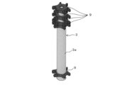
- a plurality of connecting rings 9 are attached to the outer periphery of the shaft 3.
- the plurality of connecting rings 9 are arranged at predetermined intervals in the axial direction of the shaft 3.
- a plurality of arms 7 (three in this embodiment) are rotatably attached to each of the connecting rings 9.
- the plurality of arms 7 project radially from the connecting ring 9 and are arranged in the circumferential direction with substantially the same phase spacing.
- One end of the arm 7 is connected to the connecting ring 9 via a hinge 10 whose rotation axis direction is orthogonal to the shaft 3.
- the length of each arm 7 is substantially the same.
- the arm 7 has a flat columnar shape.
- Wings 6 are rotatably attached to the other ends of a plurality of arms 7 arranged in the same phase in the circumferential direction and arranged in the axial direction.
- the airfoil 6 has a flat columnar shape extending along the shaft 3 and has an airfoil cross-sectional shape in a plan view.
- the other end of the arm 7 is connected to the blade 6 via a hinge 10 whose rotation axis direction is orthogonal to the shaft 3.
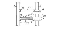
- the arm 7 arranged at the position closest to the floating body 2 (hereinafter, also referred to as the first arm 71), and the arm 7 arranged next to the first arm 71 in the axial direction (hereinafter, also referred to as the second arm 72).
- a reinforcing member 8 is provided between the two.
- the reinforcing member 8 has a flat columnar shape, and one end of the reinforcing member 8 is connected to the connecting portion between the first arm 71 and the wing 6 via a hinge 12 whose rotation axis direction is orthogonal to the shaft 3. ..
- the other end of the reinforcing member 8 is fixed to the connecting portion between the second arm 72 and the shaft 3 by the fixing member 11.
- Reinforcing fiber plastic material is used for the wing 6, the arm 7, and the reinforcing member 8, and since the wing 6, the arm 7, and the reinforcing member 8 have a substantially constant flat shape over the length direction, they are continuous at high speed. And can be manufactured, and the manufacturing cost can be reduced. Further, the weight of the wing 6, the arm 7, and the reinforcing member 8 can be reduced.
- An aluminum material may be used instead of the reinforced fiber plastic material.
- a power generation device 4 is attached to the outer periphery of the shaft 3 between the first arm 71 and the floating body 2.
- the power generation device 4 is moored by a plurality of ropes 5, and the rotation of the power generation device 4 around the axis is restricted.
- the power generation device 4 When wind power acts on the blade 6, the floating body 2 and the shaft 3 rotate around the axis.
- the power generation device 4 does not rotate. That is, the shaft 3 and the power generation device 4 rotate relatively around the axis, and the power generation device 4 generates power by the rotation of the shaft 3.
- Power generation is performed, for example, by meshing gears provided on the shaft 3 and the power generation device 4, or by providing an electromagnet and a coil on the shaft 3 and the power generation device 4. Permanent magnets may be used instead of electromagnets.
- FIG. 2 to 5 are schematic views illustrating an assembly process of the floating wind power generator 1.
- the floating body 2 and the shaft 3 are placed sideways on the ground 50, and the connecting ring 9, the arm 7, and the wing 6 are attached to the shaft 3.
- the arm 7 and the wing 6 are attached to the shaft 3 in a substantially parallel state. That is, the arm 7 and the wing 6 are folded in a direction approaching the shaft 3.
- the floating wind power generator 1 is transported to the water surface 51, placed on the auxiliary floating body 40, and towed to a desired position.
- a ballast material such as water, an iron material, and a rock is put into the floating body 2, and the floating body 2 and the shaft 3 stand up.
- the floating body 2 is formed with an opening for inserting the ballast material.
- each arm 7 is rotated toward the water surface 51, and each wing 6 is moved in a direction away from the shaft 3. That is, the wings 6 are deployed.
- a wire (not shown) is attached to the arm 7 and the wing 6 in advance, the arm 7 and the wing 6 facing the water surface 51 by their own weight are held by the wire, the amount of movement of the wire is controlled, and the wing 6 is gradually expanded.
- one end of the reinforcing member 8 is rotatably connected to the connecting portion between the first arm 71 and the wing 6. At this time, the other end of the reinforcing member 8 is a free end.
- a winch 20 is installed on the second arm 72, and a wire 21 is pulled out from the winch 20 and connected to the other end of the reinforcing member 8. After that, the winch 20 is driven to bring the other end of the reinforcing member 8 close to the connecting portion between the second arm 72 and the shaft 3, and the winch 20 is fixed to the connecting portion by the fixing member 11.
- a ladder for the worker to move and an operation unit for operating the winch 20 are provided in the shaft 3, and the operator can operate the operation unit to control the drive of the winch 20.
- the floating wind power generator 1 is made smaller by bringing the arm 7 and the wing 6 closer to the shaft 3, and the towing on water is performed. It will be easier. Further, the arm 7 and the wing 6 may be deployed at a desired position, eliminating the need for the work of attaching the arm 7 and the wing 6 to the shaft 3 on the water, reducing the installation cost, labor saving and time reduction of the installation work. Can be planned. Further, by rotating the arm 7 and the wing 6, the wing 6 can be deployed.
- the reinforcing member 8 by attaching the reinforcing member 8 and forming the truss structure, it is possible to prevent the deployed wings 6 and the arm 7 from rotating toward the floating body 2 due to their own weight and to prevent them from being folded. Further, the arm 7 and the wing 6 can be reinforced. Further, by using a reinforced fiber plastic material or an aluminum material for the wing 6, the arm 7, and the reinforcing member 8, the weight of the wing 6, the arm 7, and the reinforcing member 8 can be reduced. Further, the manufacturing cost of the blade 6, the arm 7, and the reinforcing member 8 can be suppressed.
- FIG. 6 is a schematic enlarged view of the arm 7, the blade 6, and the reinforcing member 8 of the floating wind power generator 1 whose configuration has been partially changed.
- the reinforcing member 8 may be attached as follows.
- a connecting ring 90 is slidably attached to the outer periphery of the shaft 3 between the first arm 71 and the second arm 72.
- the connecting ring 90 is arranged at a position close to the first arm 71.
- one end of the reinforcing member 8 is connected to the connecting portion between the first arm 71 and the wing 6 via a hinge 12.
- the other end of the reinforcing member 8 is connected to the connecting ring 90 via a hinge 10 that rotates about an axis orthogonal to the shaft 3.
- the connecting ring 90 is moved toward the second arm 72, the other end of the reinforcing member 8 is adjacent to the connecting portion between the second arm 72 and the connecting ring 9, and the connecting ring 90 is fixed to the shaft 3.
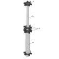
- FIGS. 7A to 7C are perspective views showing the telescopic shaft 3.
- the shaft 3 is configured to be expandable and contractible.
- the shaft 3 includes a cylindrical large diameter portion 3a, a middle diameter portion 3b, and a small diameter portion 3c.
- the diameter of the middle diameter portion 3b is smaller than the diameter of the large diameter portion 3a, and the middle diameter portion 3b is arranged in the large diameter portion 3a.
- a locking portion (not shown) that locks to the large diameter portion 3a is formed in the middle diameter portion 3b.
- the middle diameter portion 3b can be pulled out until the locking portion locks on the large diameter portion 3a.
- the diameter of the small diameter portion 3c is smaller than the diameter of the middle diameter portion 3b, and the small diameter portion 3c is arranged in the middle diameter portion 3b.
- a locking portion (not shown) that locks to the middle warp portion 3b is formed in the small diameter portion 3c.
- the small diameter portion 3c can be pulled out until the locking portion is locked to the middle warp portion 3b.
- the direction of pulling out the middle warp portion 3b and the small diameter portion 3c is the axial direction of the shaft 3 and is the same direction.
- the middle diameter portion 3b is housed in the large diameter portion 3a
- the small diameter portion 3c is housed in the middle diameter portion 3b.
- the small diameter portion 3c is pulled out until the locking portion is locked to the middle diameter portion 3b, and further, as shown in FIG. 7C, the locking portion engages with the large diameter portion 3a. Pull out the middle part 3b until it stops. Then, the small diameter portion 3c and the middle warp portion 3b are fixed in a pulled out state.
- FIG. 8 is a partially enlarged schematic view of the first arm 71, the second arm 72, and the shaft 3.
- the wing 6 is connected only to the large diameter portion 3a via the first arm 71 and the second arm 72. Since the middle diameter portion 3b and the small diameter portion 3c are arranged inside the large diameter portion 3a, the middle diameter portion 3b and the small diameter portion 3c and the wing 6 cannot be connected by the arm 7. That is, the arm 7 connecting the middle warp portion 3b, the small diameter portion 3c, and the wing 6 is removed.
- the shaft 3 is contracted, and the first arm 71, the second arm 72 and the wing 6 are folded.
- the wing 6 As shown in FIG. 8, after the shaft 3 stands on the water, the wing 6, the first arm 71 and the second arm 72 are deployed. After that, the shaft 3 is extended, and the middle warp portion 3b, the small diameter portion 3c, and the wing 6 are connected by the arm 7.
- a wire and a winch are used for the installation of the arm 7, for example.
- the shaft 3 is contracted at the time of towing to facilitate towing. Further, the shaft 3 can be erected at a desired position and then extended to deploy the wing 6.
- the floating wind power generator 1 protects the shaft 3, wings 6, arms 7, connecting rings 9, hinges 10, 12 or power generator 4 from moisture, for example, seawater droplets.
- a cover is provided for this.
- a device for supplying lubricating oil may be provided at the contact points of the parts, for example, the hinges 10 and 12.
Landscapes
- Engineering & Computer Science (AREA)
- Life Sciences & Earth Sciences (AREA)
- Sustainable Development (AREA)
- Sustainable Energy (AREA)
- Chemical & Material Sciences (AREA)
- Combustion & Propulsion (AREA)
- Mechanical Engineering (AREA)
- General Engineering & Computer Science (AREA)
- Wind Motors (AREA)
Priority Applications (1)
| Application Number | Priority Date | Filing Date | Title |
|---|---|---|---|
| JP2021519390A JPWO2020230685A1 (https=) | 2019-05-10 | 2020-05-07 |
Applications Claiming Priority (2)
| Application Number | Priority Date | Filing Date | Title |
|---|---|---|---|
| JP2019089827 | 2019-05-10 | ||
| JP2019-089827 | 2019-05-10 |
Publications (1)
| Publication Number | Publication Date |
|---|---|
| WO2020230685A1 true WO2020230685A1 (ja) | 2020-11-19 |
Family
ID=73289025
Family Applications (1)
| Application Number | Title | Priority Date | Filing Date |
|---|---|---|---|
| PCT/JP2020/018523 Ceased WO2020230685A1 (ja) | 2019-05-10 | 2020-05-07 | 浮体式水上風車及び浮体式水上風車の設置方法 |
Country Status (2)
| Country | Link |
|---|---|
| JP (1) | JPWO2020230685A1 (https=) |
| WO (1) | WO2020230685A1 (https=) |
Citations (10)
| Publication number | Priority date | Publication date | Assignee | Title |
|---|---|---|---|---|
| GB2407114A (en) * | 2003-10-15 | 2005-04-20 | Arup Group Ltd | A method of installing an offshore structure |
| WO2010110330A1 (ja) * | 2009-03-24 | 2010-09-30 | 戸田建設株式会社 | 洋上風力発電設備及びその施工方法 |
| US20110042958A1 (en) * | 2007-02-27 | 2011-02-24 | Vaxsis Inc. | Collapsible vertical-axis turbine |
| JP2011038482A (ja) * | 2009-08-12 | 2011-02-24 | Nasu Denki Tekko Co Ltd | 風力発電用風車 |
| US20110241347A1 (en) * | 2008-12-18 | 2011-10-06 | Single Buoy Moorings Inc. | Removable offshore wind turbines with pre-installed mooring system |
| WO2013069757A1 (ja) * | 2011-11-11 | 2013-05-16 | Nakamura Takuju | 流体力利用構造物 |
| US20130216379A1 (en) * | 2012-02-21 | 2013-08-22 | Clean Green Energy LLC | Fluid driven vertical axis turbine |
| JP2014058959A (ja) * | 2012-09-14 | 2014-04-03 | M Craft:Kk | 風力発電機 |
| JP2017218998A (ja) * | 2016-06-09 | 2017-12-14 | 達広 佐野 | 風力発電装置 |
| JP2019010608A (ja) * | 2017-06-29 | 2019-01-24 | 聡 安斎 | 超微細気泡発生装置 |
-
2020
- 2020-05-07 WO PCT/JP2020/018523 patent/WO2020230685A1/ja not_active Ceased
- 2020-05-07 JP JP2021519390A patent/JPWO2020230685A1/ja active Pending
Patent Citations (10)
| Publication number | Priority date | Publication date | Assignee | Title |
|---|---|---|---|---|
| GB2407114A (en) * | 2003-10-15 | 2005-04-20 | Arup Group Ltd | A method of installing an offshore structure |
| US20110042958A1 (en) * | 2007-02-27 | 2011-02-24 | Vaxsis Inc. | Collapsible vertical-axis turbine |
| US20110241347A1 (en) * | 2008-12-18 | 2011-10-06 | Single Buoy Moorings Inc. | Removable offshore wind turbines with pre-installed mooring system |
| WO2010110330A1 (ja) * | 2009-03-24 | 2010-09-30 | 戸田建設株式会社 | 洋上風力発電設備及びその施工方法 |
| JP2011038482A (ja) * | 2009-08-12 | 2011-02-24 | Nasu Denki Tekko Co Ltd | 風力発電用風車 |
| WO2013069757A1 (ja) * | 2011-11-11 | 2013-05-16 | Nakamura Takuju | 流体力利用構造物 |
| US20130216379A1 (en) * | 2012-02-21 | 2013-08-22 | Clean Green Energy LLC | Fluid driven vertical axis turbine |
| JP2014058959A (ja) * | 2012-09-14 | 2014-04-03 | M Craft:Kk | 風力発電機 |
| JP2017218998A (ja) * | 2016-06-09 | 2017-12-14 | 達広 佐野 | 風力発電装置 |
| JP2019010608A (ja) * | 2017-06-29 | 2019-01-24 | 聡 安斎 | 超微細気泡発生装置 |
Also Published As
| Publication number | Publication date |
|---|---|
| JPWO2020230685A1 (https=) | 2020-11-19 |
Similar Documents
| Publication | Publication Date | Title |
|---|---|---|
| CN108349713B (zh) | 用于安装风力涡轮机的起吊系统 | |
| EP2606228B1 (en) | Offshore wind turbine and methods of installing same | |
| KR101611779B1 (ko) | 연 지상 스테이션과 이를 이용하는 시스템 | |
| US7296974B2 (en) | Wind energy turbine | |
| US8668455B2 (en) | Turbine wheel | |
| GB2469740A (en) | Extraction of energy from the wind using kites | |
| US7775760B1 (en) | Turbine wheel | |
| MXPA06015165A (es) | Turbina de viento de eje vertical. | |
| JP2015028298A (ja) | 流体力利用構造物 | |
| GB2461265A (en) | Tidal turbine with limited axial thrust | |
| WO2017008818A1 (en) | Methods for erecting or dismantling a multirotor wind turbine | |
| CN101535582A (zh) | 用于构建和包覆风力涡轮机塔架的提升系统及装置 | |
| CN105129629B (zh) | 大部件提升系统及其拆卸方法、大部件提升方法 | |
| EP3992451B1 (en) | Method and system for attaching vortex suppression devices to a wind turbine tower | |
| EP3631193B1 (en) | Method for dismantling a wind turbine and erecting an airborne wind energy generating system | |
| EP2487364A2 (en) | Vessel and method for mounting an offshore wind turbine | |
| WO2020230685A1 (ja) | 浮体式水上風車及び浮体式水上風車の設置方法 | |
| JP4547039B1 (ja) | 風力発電用ローターブレードの取り付け方法 | |
| US20250237195A1 (en) | Methods and devices for vibration mitigation on wind turbines | |
| EP4413257B1 (en) | Floating foundation for wind turbine generators | |
| EP4602264A1 (en) | Method for handling a wind turbine blade using a crane system | |
| WO2026087037A1 (en) | Mounting wind turbine components to offshore wind turbine tower structures | |
| HK1180750B (en) | Offshore wind turbine and methods of installing same | |
| PL216202B1 (pl) | Elektrownia wiatrowa |
Legal Events
| Date | Code | Title | Description |
|---|---|---|---|
| 121 | Ep: the epo has been informed by wipo that ep was designated in this application |
Ref document number: 20806206 Country of ref document: EP Kind code of ref document: A1 |
|
| ENP | Entry into the national phase |
Ref document number: 2021519390 Country of ref document: JP Kind code of ref document: A |
|
| NENP | Non-entry into the national phase |
Ref country code: DE |
|
| 122 | Ep: pct application non-entry in european phase |
Ref document number: 20806206 Country of ref document: EP Kind code of ref document: A1 |