WO2020227809A1 - Skin torsionometer - Google Patents
Skin torsionometer Download PDFInfo
- Publication number
- WO2020227809A1 WO2020227809A1 PCT/CA2020/000075 CA2020000075W WO2020227809A1 WO 2020227809 A1 WO2020227809 A1 WO 2020227809A1 CA 2020000075 W CA2020000075 W CA 2020000075W WO 2020227809 A1 WO2020227809 A1 WO 2020227809A1
- Authority
- WO
- WIPO (PCT)
- Prior art keywords
- skin
- torsionometer
- sensor
- operably connected
- processor
- Prior art date
Links
Classifications
-
- A—HUMAN NECESSITIES
- A61—MEDICAL OR VETERINARY SCIENCE; HYGIENE
- A61B—DIAGNOSIS; SURGERY; IDENTIFICATION
- A61B5/00—Measuring for diagnostic purposes; Identification of persons
- A61B5/44—Detecting, measuring or recording for evaluating the integumentary system, e.g. skin, hair or nails
- A61B5/441—Skin evaluation, e.g. for skin disorder diagnosis
- A61B5/442—Evaluating skin mechanical properties, e.g. elasticity, hardness, texture, wrinkle assessment
-
- A—HUMAN NECESSITIES
- A61—MEDICAL OR VETERINARY SCIENCE; HYGIENE
- A61B—DIAGNOSIS; SURGERY; IDENTIFICATION
- A61B5/00—Measuring for diagnostic purposes; Identification of persons
- A61B5/0048—Detecting, measuring or recording by applying mechanical forces or stimuli
- A61B5/0057—Detecting, measuring or recording by applying mechanical forces or stimuli by applying motion other than vibrations, e.g. rolling, rubbing, applying a torque, tribometry
Definitions
- a device for determining the elasticity and tautness of skin including a housing, a torsionometer rotationally attached to the housing having a lower surface designed and configured to adhere to skin, a sensor configured to monitor rotation velocity of the torsionometer operably connected to the torsionometer and contained within the housing.
- the sensor may be selected from optical sensors, cameras, video cameras, smart phones, optical encoders, and the like and combinations thereof, and in certain embodiments, the sensor may be an optical encoder.
- the device may further include a processor operably connected to the sensor, a display, indicator lights, buttons, hardware for transmitting data, and the like and combinations thereof.
- the hardware for transmitting data may be selected from cords, connectors, dongles, WiFi hardware, Bluetooth hardware, or other wireless network hardware, and combinations thereof.
- the device may further include a processor operably connected to the sensor, and the processor may be configured to determine the Young’s modulus of the skin.
- the torsionometer may be substantially cylindrical in shape, and in some embodiments, the torsionometer may include a rotatable shaft operably connected to the torsionometer and the sensor.
- the device may include a vacuum pump operably connected to the torsionometer and configured to adhere the torsionometer to the skin by suction, and in some embodiments, a vacuum gauge operably connected to the vacuum pump and operably connected to the processor, and the processor may be configured to calculate a density of skin adhered to the torsionometer.
- Other embodiments are directed to a method for measuring the elasticity or tautness of skin by measuring recoil speed associated with return of twisted skin to a natural position.
- the method may include calculating a Young’s modulus of the skin based on the recoil speed, and in some embodiments, the method may include measuring a degree of rotation of the twisted skin, measuring an angular velocity of the return of the twisted skin to a natural position, measuring an acceleration of the return of the twisted skin to a natural position, and the like and combinations thereof.
- the method may be carried out on facial skin, arm skin, leg skin, and the like and combinations thereof.
- FIG. 1 is a diagram illustrating one example of a skin torsionometer embodied by the invention.
- FIG. 2 is a diagram illustrating one example of a skin torsionometer embodied by the invention.
- FIG. 3 is a diagram illustrating one example of a skin torsionometer embodied by the invention.
- FIG. 4 is a diagram illustrating one example of a system including a skin torionometer embodied by the invention and a computing device configured to capture images.
- FIG. 5A is a diagram illustrating one example of a device including a torsionometer.
- FIG. 5B is a diagram illustrating one example of a device including a torsionometer.
- FIG. 6 is a block diagram showing methods encompassed by the invention.
- FIG. 7 is a block diagram showing method encompassed by the invention.
- FIG. 8 is a bar and line graph illustrating example data collected using the device of embodiments.
- the word“about” when immediately preceding a numerical value means a range of plus or minus 10% of that value, e.g,“about 50” means 45 to 55,“about 25,000” means 22,500 to 27,500, etc., unless the context of the disclosure indicates otherwise, or is inconsistent with such an interpretation.
- “about 49, about 50, about 55, “about 50” means a range extending to less than half the interval(s) between the preceding and subsequent values, e.g, more than 49.5 to less than 52.5.
- the phrases“less than about” a value or“greater than about” a value should be understood in view of the definition of the term “about” provided herein.
- the term“patient” and“subject” are interchangeable and may be taken to mean any living organism which may be treated with compounds of the present invention.
- the terms “patient” and“subject” may include, but is not limited to, any non-human mammal, primate or human.
- the“patient” or“subject” is a mammal, such as mice, rats, other rodents, rabbits, dogs, cats, swine, cattle, sheep, horses, primates, or humans.
- the patient or subject is an adult, child or infant.
- the patient or subject is a human.
- Embodiments of the invention are directed to a devices, systems, and methods for measuring the tautness and elasticity of skin.
- the torsionometer includes a rigid disk having an upper and a lower surface. The lower surface includes an adhesive and the upper surface includes one or more marking.
- the torsionometer is used by adhering the torsionometer to the skin of a subject and twisting the torsionometer. The degree of movement provides a measurement of the taughtness and elasticity of the skin of the patient.
- the torsionometer may be part of a system that includes an optical sensor operably associated with processor.
- the optical sensor may monitor movement of the markings on the upper surface of the torsionometer and the processor may use this information to measure the tautness of skin based on the amount of rotation, torque, rotational force, acceleration, and the like during return after the torsionometer is released, or other measurement that can provide a measurement of and elasticity.
- the torsionometer may be part of a device that measures rotation of the torsionometer using a sensor, such as a optical encoder, torque meter, or other sensor capable of measuring rotation, torque, rotational force, acceleration, and the like.
- Figures 1-3 show various examples of the skin torsionometer. FIG.
- FIG. 1 shows a skin torsionometer 1, having an upper surface 10 and a lower surface 11, and a marking 12 on the upper surface 10.
- FIG. 2 shows a skin torsionometer 2, having an upper surface 20 and a lower surface 21, and markings 22 is on the upper surface 20.
- FIG. 3 shows a skin torsionometer 3, having an upper surface 30 and a lower surface 31, and various markings 32 on the upper surface.
- the markings 12, 22, 32 provide a means for observing the torsion of the skin when the skin torsionometers 1, 2, 3 are rotated on the skin. For example, rotation of the skin torsionometer 1 of FIG.
- the change in angle may be observed as the torsionometer 1 is rotated, and in some embodiments, the skin may be marked at the location of the marking 12 at a first position before the torsionometer is rotated.
- the markings 22 on torsionometer 2 of FIG. 2 can be used in the same way to observe the change in angle of the torsionometer 2 at the center 23 of the torsionometer.
- the torsionometer may include markings that allow for multiple, simultaneous calculation of the degree of rotation, the recoil speed, return velocity, acceleration, angular velocity, and the like or combinations thereof.
- FIG. 3 illustrates a torsionometer 3 having a series of markings 32 on an upper surface 30 that are located at various distances from a center marking 33.
- the lower surface 31 can be designed as discussed above to adhere to the skin of the subject.
- the computing device configured for image capture may align images based on the center marking 33 and identify a resting position and a rotated position of the torsionometer for each of the series of markings 32.
- the degree of rotation, the recoil speed, return velocity, acceleration, angular velocity, and the like or combinations thereof can be determined for each marking of the series of markings independently, and the final calculation can be an average of these measured values.
- the torsionometers 1 ,2 of various embodiments may be of any diameter sufficient to allow the user to hold the torsionometer 1,2 against the skin and rotate it against the resistance of the skins inherent elestasticity.
- the torsionometer 1,2 may have a diameter of about 1 inch (about 2.5 centimeters (cm)) to about 4 inches (about 10.2 cm) or about 1.5 inches (about 3.8 cm) to about 3 inches (about 7.6 cm) or any individual diameter or range encompassed by these example ranges, and in certain embodiments, the torionsometer 1,2 may have a diameter of about 2.2 inches (about 55 cm).
- the lower surface 11,21 of the torionsometer 1,2 may include an adhesive to hold the torionometer 1,2 on the skin of the patient during testing.
- the adhesive may be an adhesive compound, such as silicone adhesives, rubber adhesives, polyurethane adhesives, or hydrocolloid blended with adhesives such as polyisobutylenes or styrene-soprene-styrenes.
- the adhesive may generally be designed to balance internal cohesion or shear as well as tack and peel strength to provide sufficient adhesive strength to enable it to stick to objects, including human skin and allow for rotation of the trosionometer 1,2 without releasing during use, but that can be released from the skin following use without causing discomfort to the patient after use.
- the adhesive may be reusable.
- the adhesive may be applied in layers, for example, the adhesive may be layers of double-sided medical tape so that after each use the user may remove a layer of the tape exposing a fresh layer of adhesive.
- the lower surface 11,21 of the torisonometer 1,2 may be textured to increase the surface area of the lower surface 11,21.
- dimples or bumps can be provided on the lower surface 11,21 of the torsionometer 1,2, and in other embodiments, the lower surface 11,21 may include a series of ridges, waves, or paddles extending radially from the center of the torsionometer 1,2. The ridges, waves, or paddles may be sufficiently large to hold the torsionometer 1 ,2 to the skin of the subj ect without breaching the skin of the subj ect.
- FIG. 4A-B illustrates the change in angle observed during use of the torsionometer.
- Panel A of FIG. 4 shows the torsionometer 4 of FIG. 1 in a first position. The position of the marking 42 is illustrated by the dashed line 44.
- the torsionometer 4 is rotated about a center axis 45 as indicated by the arrow R.
- Panel B shows the torsionometer 4 in the second position after rotation as indicated by the change in position of the marking 42.
- the torsionometer is rotated against the tautness and elasticity of the skin. Therefore, the change in angle A at the center of the torsionometer 4 provides a measure of the tautness and elasticity of the skin. For example, a change in angle A of 1 degrees or less, a change in angle A of 15 degrees, a change in angle A of 30 degrees, and a change in angle A of less than 45 degree may indicate different tightness in the skin.
- the change in angle A may provide evidence of the amount and health of the elastin and collagen in the skin.
- Healthy skin with abundant elastin and collagen may exhibit a change in angle A of about 1 degree to 5 degrees or less and return upon release of the torsionometer of less than about 1 second, less than about 0.5 seconds, or less than about 0.1 seconds.
- Aged or damaged skin with lower concentrations of healthy elastin and collagen may exhibit a change in angle A of up to about 45 degrees and return upon release of the torsionometer of up to about 20 seconds, about 5 to about 20 seconds, about 8 to about 15 seconds, or any individual time or range encompassed by these example ranges.
- the torsionometer may be used to document the effect of skin care products that are formulated to improve the tautness, firmness, and elasticity of skin.
- a subject may use the torsionometer before administering a skin care product to provide a baseline tautness and elasticity.
- the subject may administer the skin care product and use the torsionometer to document any improvement is tautness, firmness, and elasticity based on a change in angle A from the baseline measurement.
- the subject mays use the torsionometer to measure skin elasticity or tightening after exposure to, for example, the Sun or other environmental conditions, after treatment with medical devices, or to monitor changes in skin taughtness after surgery.
- Such systems may generally include a torsionometer 1,2 such as those described above and a device for measuring the degree of rotation of the torsionometer 1,2, the acceleration or rate of return of the torsionometer 1,2 upon release, or any measure of movement of the device that can be used to determine the tightness of skin.
- Such measurements can be obtained using various devices and by various means. For example, such measurements can be obtained using accelerometers associated with the torsionometer 1,2, or in other embodiments, such measurements can be obtained by monitoring the movement of the torsionometer 1,2 with a secondary device such as a smartphone or tablet. Measurements can be obtained by monitoring, for example, change in light wavelength, magnetic response, phase retardation, ultrasound echo processes, optical laser, or comparing video or still images taken at various times during use of the torsionometer.
- Data can be collected and aggregated using, for example, WiFi, Bluetooth, or other wireless network, and stored in a separate computing device to allow for analysis of groups of patients results.
- Various embodiments include of such systems are illustrated in FIG. 4C.
- Such systems may include a skin torsionometer 40 such as those discussed above have one or more markings 42, and a computing device 400 communicatively coupled to a camera, video camera, or other image data capturing means such as a smartphone or tablet having a camera 420 and a display 410.
- the skin torsionometer 40 may be adhered to the skin of a subject and the handheld device 400 may be used to capture an image of the skin torsionometer 40 in the first position.
- the torsionometer 40 may be rotated to a second position and the computing device 400 may be used to capture a second image of the torsionometer 40 in the second position.
- a processor associated with the computing device 400 may compare the images and calculate the change in angle at the center of the torsionometer 40.
- the change in angle A at the center of the torsionometer 4 provides a measure of the tautness and elasticity of the skin.
- the system may include an app that can be downloaded on the handheld device and provides computer readable instructions for the processor of the handheld device to capture one or more still or video images using the computing device 400 camera 420, identify the torsionometer 40 and/or the markings 42 on the torsionometer 40, and calculate the change in angle A at the center of the torsionometer, the acceleration and/or rate of release of the torsionometer 40, and the like and combinations thereof, and display the change in angle A and/or measurement of skin tightness on the display 410 of the computing device 400.
- the computer readable instructions may further cause the processor to display the still or video images captured by the camera 420 on the display 410.
- the torsionometer may be associated with a device specifically designed to measure the amount of rotation, rotational force, acceleration during return after the skin torsionometer is released or other measurement that can provide a measurement of and elasticity.
- the torsionometer 5 a may be operably attached to an optical sensor 530.
- the torsionometer 5 may have a substantially cylindrical shape with a lower surface 51 designed and configured to adhere to skin using any of the means for adherence described above.
- the torsionometer may be sized to accomodate handling be a user, allowing the user to rotate the torsionometer and release it without interrupting the return rotation.
- the torsionometer 5 may be rotationally attached to a housing 530 by, for example, a rotatable shaft 531 that is operable connected to a sensor 532.
- Such devices may further include a processor 533, and various displays 534, indicator lights 535, and buttons 536.
- the device may further include a means for transmitting data acquired to a larger processor or computer, such as a cord, connector, or dongle 537.
- FIG. 5B is another torsionometer containing device.
- the torsionometer 5 may have a substantially cylindrical shape with a lower surface 51 designed and configured to adhere to skin using any of the means for adherence described above.
- the torsionometer 5 may be rotationally attached to a housing 530 by, for example, a rotatable shaft 531 that is operable connected to a sensor 532.
- the sensor 532 may include an optical encoder 532a.
- the optical encoder 532a may be, for example, a slotted photo interrupter or opto-interrupter.
- optical encoders 532a may include markings as described above and an optical sensor 532b may measure, for example, recoil speed, return velocity, acceleration, angular velocity, and the like, by monitoring the position of the marks over time.
- the optical encoder 532a may include alternating slots.
- an optical sensor 532b passes a beam of light through the optical encoder creating changes in conduction of the photo transistor/diode as the optical encoder 532a rotates, breaking the beam.
- the optical sensor 532b may emit light onto one side of the optical encoder 532a and detect the reflected light.
- the optical sensor may be an iOS optical sensor or other commercially available optical sensor, a camera, video camera, smart phone, and the like, and combinations thereof.
- such devices may further include a processor 533, and various displays 534, indicator lights 535, and buttons 536.
- the device may further include a means for transmitting data acquired to a larger processor or computer, such as a cord, connector, or dongle.
- the device may include hardware 538 for transmitting data by, for example, WiFi, Bluetooth, or other wireless network.
- the lower surface 51 of the torsionometer 5 may be adhered to the skin of a patient.
- the torsionometer 5 may be rotated, as indicated by arrow 540, rotating the rotatable shaft 531 while the sensor housing 530 and associated optical sensor 532 remains static.
- the torsionometer 5 may be released allowing the torsionometer 5, underlying skin, and rotatable shaft 531 to rotate in the opposite direction, as indicated by arrow 541, returning to its original position.
- the optical sensor 532 capture data relating to the amount of rotation, torsion, rotational force, acceleration, and the like.
- the processor 533 may calculate the amount of rotation, torsion, rotational force, acceleration and the like and display data relating to these calculations on the display 534 and/or transmit this data to another processing device by a cord 537 or wireless hardware 538.
- an indicator light 535 may turn on indicating that sufficient force has been applied by rotation of the skin in direction 540 to produce reproducible results.
- Various buttons 536 may control any aspect of the use of the device, such as rotation of the torsionometer 5, release of the torsionometer 5, display of results, adherence of the torsionometer 5 to skin, suction which allows the torsionometer 5 to adhere to skin, or any other function of the device.
- the device may further include a vacuum pump operably connected to the torsionometer.
- the vacuum pump may be configured to adhere the torsionometer by applying suction to the skin.
- the vacuum pump may be operably connected to a vacuum gauge that measure suction applied to skin when the torsionometer is adhered to the skin.
- the vacuum gauge may be operably connected to the processor and may transmit suction data to the processor where it can be used to calculate the density of skin adhered to the torsionometer.
- FIG. 6 shows an example method 6 for determining the rotation, the recoil speed, return velocity, acceleration, angular velocity, and the like or combinations thereof of the torsionometer.
- a computing device may be configured to operate as an image processing engine, on which each of the following steps can be executed.
- an optical sensor may be used to capture image data relating to the rotation, torque recoil speed, return velocity, acceleration, angular velocity, and the like or combinations thereof of the torsionometer.
- All commercially suitable computing devices are contemplated for use with the inventive subject matter, including for example, a mobile phone, a tablet computer, a laptop computer, an electronic book reader, a camera, a video camera, a smart phone, a kiosk, or any other device having a sensor and a user interface.
- Step 600 includes capturing first image data of the scene containing the torionsometer.
- This image data is received by the computing device or a different device communicatively coupled to the computing device such as a camera, video camera, or other image data capturing means.
- image data is used broadly to include, among other things, a still image, a video frame, a video frame delta, a video, a computer rendered image, a computer generated image or graphic, a projection, printed matter, an on-screen image, medical images, or other types of images.
- Step 610 includes compiling a first object-specific metric map of the torsionometer from the image data.
- the metric map may include at least a portion of the image data representing the torsionometer and may include mapping of color values, metric values (e.g., scalars, vectors, etc.), spacing, and the like and combinations thereof.
- the initial object-specific metric map can be generated in an empirical, data-driven fashion.
- the object-specific metric map should be lighting invariant, such that the torsionsometer may be recognized regardless of the lighting conditions under which the image data is generated. For example, as lighting conditions are varied, the imaging processing engine can execute a desired image processing algorithm on the image data to derive descriptors.
- the engine can further compile which RBG values remain invariant as the lighting is changed and yield the best results for high quality descriptors.
- the engine can further construct (e.g., automatically, manually, semi-automatically, etc.) the object-specific metric map (step 611) that indicates how the RGB should be mapped to metric values and how to generate best results under all lighting conditions.
- the first object-specific metric map of the first image data may include, for example, a circumference of the torsionsometer, the location of the center of the torsionometer, and the location of any markings on the torsionometer.
- step 620 the user rotates the torsionometer against the elasticity of the skin to which the torsionometer is attached. Rotating is continued until the rotation meets sufficient resistance to stop rotation without injuring the subject.
- Step 630 includes capturing a second image data of the scene containing the torsionometer in fully rotated position, and step 640 includes compiling a second object-specific metric map of the torsionometer from the image data.
- Compiling of the second object-specific metric map can be carried out in the same manner as compiling the first object-specific metric map, and can include constructing the object-specific metric map (step 641) that indicates the best results under all lighting conditions.
- the second object-specific metric map of the second image data may include, for example, a circumference of the torsionsometer, the location of the center of the torsionometer, and the location of any markings on the torsionometer.
- Step 650 includes comparing the first object-specific metric map and the second object-specific metric map.
- the image processing engine can compare or contrast each individual object's specific map.
- Each map can be treated has having a functional complexity with respect to the computation steps necessary to convert RGB values to individual metrics. Complexity might be measured by size of look up table, number of calculations, or other factors.
- a form of principle component analysis could operate on the various dimensions (e.g. constants, scales, operations, etc.) of the map's functions across the class of objects to reduce the features of the collective map's complexity.
- Step 650 (and any other step of the inventive subject matter) can be carried out via the image processing engine, or another engine, server or platform, distal or local.
- the first or second object-specific metric map compiled in steps 610 and 640 can be adjusted to generate a new object-specific metric map in accordance with step 651.
- the initial map can be adjusted by tuning the function in a manner effective to enhance differentiation of descriptors generated by the implementation of the feature identification algorithm (e.g. SIFT, FAST, etc.) as executed on the portion of the image.
- the feature identification algorithm e.g. SIFT, FAST, etc.
- the first or second object-specific image maps may be manipulated to align the orientation of the first and second object-specific image maps.
- Aligning the orientation of the first and second image maps may include, for example, aligning centers of the image maps, enlarging or reducing the size of the torsionometers in the image map to make the image maps equally sized and dimensioned, and the like and combinations thereof.
- the method may include Step 652 in which one or more characteristics can be removed from image data at the pixel-level to allow for increased and more consistent differentiation of the values in the image data.
- image data may comprise various characteristics that hinder a differentiation of colors on a pixel-level basis (e.g., illumination color, illumination geometry, surface reflectance, surface geometry and view-point, diffuse reflection, specular reflection, etc.). Removal of, or zeroing out, one or more of the characteristics can improve the effectiveness of image analysis or feature identification algorithms on an image as many algorithms assume perfect diffuse reflections and consider locations of specular reflection to be outliers. Such assumption reduces the robustness of these algorithms since the presence of specular reflection is inevitable in most real-world environments.
- Step 660 includes calculating the degree of rotation of the torsionometer on the aligned first and second image maps. Calculating can be carried out by any means that results in a degree of rotation of the torsionometer.
- Step 661 calculating the recoil speed, return velocity, acceleration, angular velocity, and the like or combinations thereof of the torsionometer from the rotated position to the first position.
- Calculating the recoil speed, return velocity, acceleration, angular velocity, and the like or combinations thereof can be carried out using various means and, in particular embodiments, the calculating the recoil speed, return velocity, acceleration, angular velocity, and the like or combinations thereof can be carried out by capturing video image, identifying a first, resting position, identifying a rotated position, and determining the amount of time required for the torsionometer to return to a second, resting position from the rotated position.
- the second, resting position may be the same position as the first resting position, and in some embodiments, the second, resting position may be a position in which the torsionometer has stopped rotating away from the rotated position that is not the same as the first, resting position.
- the computing device configured for image capture may identify a final resting position on skin that has lost elasticity.
- Such methods may include the step of displaying the degree of rotation, the recoil speed, return velocity, acceleration, angular velocity, and the like and combinations thereof.
- the degree of rotation can be displayed as a number such as, for example, 1 degree, 15 degrees, 30 degrees, or 45 degrees
- the recoil speed, return velocity, acceleration, angular velocity, and the like or combinations thereof can be displayed as a numerical value such as, less than about 0.1 second, less than about 0.5 seconds and up to about 20 seconds, less than about 0.2 seconds to about 15 seconds, about 1 to about 15 seconds, about 1.5 to about 10 seconds, or any individual time or range encompassed by these example ranges.
- the display may provide an independent measurement providing the user with an indication of the elasticity, firmness, taughtness, and/or overall health of the skin.
- the calculations obtained from methods described above can be combined and weighted, and the skin can overall elasticity, firmness, or taughtness can be measured on a 1-10 or 1-5 scale.
- the app may contain instructions for understanding the measured number and display examples of skin falling within the applicable measurement.
- Additional embodiments include methods for measuring the elasticity of skin using the device illustrated in FIG. 5 and described above.
- the user rotates the torsionometer against the elasticity of the skin to which the torsionometer is attached in step 720. Rotating is continued until the rotation meets sufficient resistance to stop rotation without injuring the subject.
- the rotating the torsionometer causes an optical senosr associated with the torsionometer to rotate to a first position.
- Step 730 the optical sensor is activated by rotation of the torsionometer.
- Step 740 includes releasing the torsionometer, causing the torsionometer in the opposite direction of the rotation in Step 720, and reversing twisting of the underlying skin.
- the sensor may capture data, Step 750 relating to the amount of rotation, rotational force, acceleration, and the like, by monitoring transmission of light through slits in the optical encoder.
- Step 760 recoil speed, return velocity, acceleration, angular velocity, and the like may be calculated by a processor associated with the optical sensor.
- the processor may be associated directly with the optical sensor and these data may be transmitted to a processor that can display, save, and/or compile the data.
- the optical sensor may transmit raw data to a processor that can use the data to calculate recoil speed, return velocity, acceleration, angular velocity, and the like, display, save and/or compile these data.
- a processor that can use the data to calculate recoil speed, return velocity, acceleration, angular velocity, and the like, display, save and/or compile these data.
- such methods may include the step of displaying the degree of rotation, the recoil speed, torsion, return velocity, acceleration, angular velocity, and the like and combinations thereof.
- the degree of rotation can be displayed as a number such as, for example, 1 degree, 15 degrees, 30 degrees, or 45 degrees, and the recoil speed, return velocity, acceleration, angular velocity, and the like or combinations thereof, can be displayed as a numerical value such as, less than about 0.1 second, less than about 0.5 seconds and up to about 20 seconds, less than about 0.2 seconds to about 15 seconds, about 1 to about 15 seconds, about 1.5 to about 10 seconds, or any individual time or range encompassed by these example ranges.
- the display may provide an independent measurement providing the user with an indication of the elasticity, firmness, taughtness, and/or overall health of the skin.
- the calculations obtained from methods described above can be combined and weighted, and the skin can overall elasticity, firmness, or taughtness can be measured on a 1-10 or 1-5 scale.
- the app may contain instructions for understanding the measured number and display examples of skin falling within the applicable measurement.
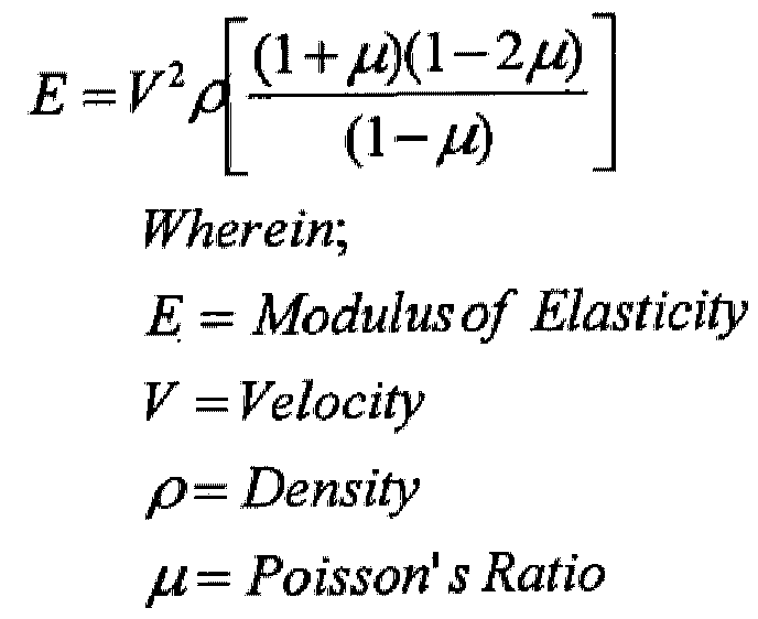
- elasticity can be measured as a function of the modulus of elasticity, e.g. Young's modulus. Young’s modulus can be calculated as follows:
- Density (p) can be calculated as follows:
- Density can be constant based on the average density of skin in the region tested, for example, the density of skin on the forehead or the density of skin on the forearm. In other embodiments, density can be calculated by irradiating the skin and detecting, for example, absorbance or scattering. Similarly, Poisson’s ratio (m), which is calculated as follows:
- Poisson’s ratio can be calculated based on the change in length and width of the skin when twisted under the torsionometer.
- the app may store various measured values such as, the degree of rotation, recoil speed, acceleration, and the like and combinations thereof, in a transitory storage medium.
- the app may display these measurements in, for example, graphically or on a spreadsheet.
- the app may sequentially store and transmit various measured values to a repository, where the data can be used by formularies and skin care professionals to monitor the effect of skin care products and treatment regimens. For example, the data may be used to compile patient reported outcomes for skin care products and treatment regimens under review by the FDA.
Landscapes
- Health & Medical Sciences (AREA)
- Life Sciences & Earth Sciences (AREA)
- Medical Informatics (AREA)
- Biophysics (AREA)
- Pathology (AREA)
- Engineering & Computer Science (AREA)
- Biomedical Technology (AREA)
- Heart & Thoracic Surgery (AREA)
- Physics & Mathematics (AREA)
- Molecular Biology (AREA)
- Surgery (AREA)
- Animal Behavior & Ethology (AREA)
- General Health & Medical Sciences (AREA)
- Public Health (AREA)
- Veterinary Medicine (AREA)
- Dermatology (AREA)
- Measuring And Recording Apparatus For Diagnosis (AREA)
- Measurement Of The Respiration, Hearing Ability, Form, And Blood Characteristics Of Living Organisms (AREA)
Abstract
Description


Claims
Priority Applications (4)
| Application Number | Priority Date | Filing Date | Title |
|---|---|---|---|
| EP20805756.2A EP3809965A4 (en) | 2019-05-13 | 2020-06-24 | Skin torsionometer |
| CA3098854A CA3098854A1 (en) | 2019-05-13 | 2020-06-24 | Skin torsionometer |
| US17/054,103 US20210196185A1 (en) | 2018-05-11 | 2020-06-24 | Skin torsionometer |
| JP2020563987A JP2022532456A (en) | 2019-05-13 | 2020-06-24 | Skin fertility transfer |
Applications Claiming Priority (2)
| Application Number | Priority Date | Filing Date | Title |
|---|---|---|---|
| US201916409904A | 2019-05-13 | 2019-05-13 | |
| US16/409,904 | 2019-05-13 |
Publications (2)
| Publication Number | Publication Date |
|---|---|
| WO2020227809A1 true WO2020227809A1 (en) | 2020-11-19 |
| WO2020227809A8 WO2020227809A8 (en) | 2021-08-19 |
Family
ID=73289160
Family Applications (1)
| Application Number | Title | Priority Date | Filing Date |
|---|---|---|---|
| PCT/CA2020/000075 WO2020227809A1 (en) | 2018-05-11 | 2020-06-24 | Skin torsionometer |
Country Status (4)
| Country | Link |
|---|---|
| EP (1) | EP3809965A4 (en) |
| JP (1) | JP2022532456A (en) |
| CA (1) | CA3098854A1 (en) |
| WO (1) | WO2020227809A1 (en) |
Citations (5)
| Publication number | Priority date | Publication date | Assignee | Title |
|---|---|---|---|---|
| US4396025A (en) | 1980-07-01 | 1983-08-02 | L'oreal | Apparatus for measuring the elastic characteristics of skin |
| DE4229549A1 (en) | 1992-09-04 | 1994-03-10 | Christoph Prof Dr Hartung | Determination method for mechanical properties of biological tissue - using in situ measuring head applying dynamic twisting |
| WO2005064311A1 (en) | 2003-12-27 | 2005-07-14 | University Court Of The University Of Dundee | Measuring skin deflection |
| EP1513445B1 (en) | 2002-06-14 | 2006-09-06 | Courage + Khazaka electronic GmbH | Pneumatic device for measuring skin elasticity |
| US20130079643A1 (en) * | 2011-09-22 | 2013-03-28 | Lvmh Recherche | Method to measure skin elasticity and firmness |
-
2020
- 2020-06-24 EP EP20805756.2A patent/EP3809965A4/en active Pending
- 2020-06-24 CA CA3098854A patent/CA3098854A1/en active Pending
- 2020-06-24 WO PCT/CA2020/000075 patent/WO2020227809A1/en unknown
- 2020-06-24 JP JP2020563987A patent/JP2022532456A/en active Pending
Patent Citations (5)
| Publication number | Priority date | Publication date | Assignee | Title |
|---|---|---|---|---|
| US4396025A (en) | 1980-07-01 | 1983-08-02 | L'oreal | Apparatus for measuring the elastic characteristics of skin |
| DE4229549A1 (en) | 1992-09-04 | 1994-03-10 | Christoph Prof Dr Hartung | Determination method for mechanical properties of biological tissue - using in situ measuring head applying dynamic twisting |
| EP1513445B1 (en) | 2002-06-14 | 2006-09-06 | Courage + Khazaka electronic GmbH | Pneumatic device for measuring skin elasticity |
| WO2005064311A1 (en) | 2003-12-27 | 2005-07-14 | University Court Of The University Of Dundee | Measuring skin deflection |
| US20130079643A1 (en) * | 2011-09-22 | 2013-03-28 | Lvmh Recherche | Method to measure skin elasticity and firmness |
Non-Patent Citations (1)
| Title |
|---|
| See also references of EP3809965A4 |
Also Published As
| Publication number | Publication date |
|---|---|
| WO2020227809A8 (en) | 2021-08-19 |
| JP2022532456A (en) | 2022-07-15 |
| EP3809965A1 (en) | 2021-04-28 |
| EP3809965A4 (en) | 2022-06-08 |
| CA3098854A1 (en) | 2021-12-24 |
Similar Documents
| Publication | Publication Date | Title |
|---|---|---|
| AU2006206334B2 (en) | Devices and methods for identifying and monitoring changes of a suspect area on a patient | |
| US11883185B2 (en) | Systems, devices and methods for assessing milk volume expressed from a breast | |
| RU2436507C2 (en) | Methods of wound area therapy and systems for its realisation | |
| US9696897B2 (en) | Image-based measurement tools | |
| US20130162796A1 (en) | Methods and apparatus for imaging, detecting, and monitoring surficial and subdermal inflammation | |
| KR20090013216A (en) | Systems and methods for wound area management | |
| US20080045807A1 (en) | System and methods for evaluating and monitoring wounds | |
| CN103327894A (en) | Apparatus, systems, and methods for tissue oximetry and perfusion imaging | |
| TW201813585A (en) | Systems and methods for evaluation of scoliosis and kyphosis | |
| US20170078584A1 (en) | Optical dynamic imaging system | |
| Sprigle et al. | Iterative design and testing of a hand-held, non-contact wound measurement device | |
| EP2795574A1 (en) | Method for measuring the absorption of fluid in an absorbent product | |
| CN115170629A (en) | Wound information acquisition method, device, equipment and storage medium | |
| JP2023525742A (en) | Gating Machine Learning Prediction for Medical Ultrasound Images via Risk and Uncertainty Quantification | |
| US10258252B1 (en) | Wound measurement and tracking system and method | |
| US20210196185A1 (en) | Skin torsionometer | |
| WO2020227809A1 (en) | Skin torsionometer | |
| CN106419830A (en) | Method for measuring diameters of pupils | |
| US10362969B2 (en) | Image-based detection and diagnosis of diastasis recti | |
| CN116649953A (en) | Wound scanning method and device and wound scanner | |
| CN205625932U (en) | Nail growth detector | |
| WO2024090190A1 (en) | Ultrasonic inspection device, inspection method, and program | |
| RU38280U1 (en) | INFORMATION-MEASURING SYSTEM FOR THE STUDY OF HUMAN MOTOR FUNCTIONS | |
| Tarabini et al. | A prototype for the automatic measurement of the hand dimensions using the Microsoft Kinect V2 | |
| CN111991002A (en) | Method, device and equipment for measuring neck mobility |
Legal Events
| Date | Code | Title | Description |
|---|---|---|---|
| ENP | Entry into the national phase |
Ref document number: 3098854 Country of ref document: CA |
|
| ENP | Entry into the national phase |
Ref document number: 2020563987 Country of ref document: JP Kind code of ref document: A |
|
| 121 | Ep: the epo has been informed by wipo that ep was designated in this application |
Ref document number: 20805756 Country of ref document: EP Kind code of ref document: A1 |
|
| ENP | Entry into the national phase |
Ref document number: 2020805756 Country of ref document: EP Effective date: 20210121 |
|
| NENP | Non-entry into the national phase |
Ref country code: DE |