WO2020226080A1 - 液晶回折素子および積層回折素子 - Google Patents
液晶回折素子および積層回折素子 Download PDFInfo
- Publication number
- WO2020226080A1 WO2020226080A1 PCT/JP2020/017764 JP2020017764W WO2020226080A1 WO 2020226080 A1 WO2020226080 A1 WO 2020226080A1 JP 2020017764 W JP2020017764 W JP 2020017764W WO 2020226080 A1 WO2020226080 A1 WO 2020226080A1
- Authority
- WO
- WIPO (PCT)
- Prior art keywords
- liquid crystal
- crystal layer
- cholesteric liquid
- light
- cholesteric
- Prior art date
- Legal status (The legal status is an assumption and is not a legal conclusion. Google has not performed a legal analysis and makes no representation as to the accuracy of the status listed.)
- Ceased
Links
Images


Classifications
-
- G—PHYSICS
- G02—OPTICS
- G02F—OPTICAL DEVICES OR ARRANGEMENTS FOR THE CONTROL OF LIGHT BY MODIFICATION OF THE OPTICAL PROPERTIES OF THE MEDIA OF THE ELEMENTS INVOLVED THEREIN; NON-LINEAR OPTICS; FREQUENCY-CHANGING OF LIGHT; OPTICAL LOGIC ELEMENTS; OPTICAL ANALOGUE/DIGITAL CONVERTERS
- G02F1/00—Devices or arrangements for the control of the intensity, colour, phase, polarisation or direction of light arriving from an independent light source, e.g. switching, gating or modulating; Non-linear optics
- G02F1/01—Devices or arrangements for the control of the intensity, colour, phase, polarisation or direction of light arriving from an independent light source, e.g. switching, gating or modulating; Non-linear optics for the control of the intensity, phase, polarisation or colour
- G02F1/13—Devices or arrangements for the control of the intensity, colour, phase, polarisation or direction of light arriving from an independent light source, e.g. switching, gating or modulating; Non-linear optics for the control of the intensity, phase, polarisation or colour based on liquid crystals, e.g. single liquid crystal display cells
- G02F1/137—Devices or arrangements for the control of the intensity, colour, phase, polarisation or direction of light arriving from an independent light source, e.g. switching, gating or modulating; Non-linear optics for the control of the intensity, phase, polarisation or colour based on liquid crystals, e.g. single liquid crystal display cells characterised by the electro-optical or magneto-optical effect, e.g. field-induced phase transition, orientation effect, guest-host interaction or dynamic scattering
- G02F1/13718—Devices or arrangements for the control of the intensity, colour, phase, polarisation or direction of light arriving from an independent light source, e.g. switching, gating or modulating; Non-linear optics for the control of the intensity, phase, polarisation or colour based on liquid crystals, e.g. single liquid crystal display cells characterised by the electro-optical or magneto-optical effect, e.g. field-induced phase transition, orientation effect, guest-host interaction or dynamic scattering based on a change of the texture state of a cholesteric liquid crystal
-
- G—PHYSICS
- G02—OPTICS
- G02B—OPTICAL ELEMENTS, SYSTEMS OR APPARATUS
- G02B5/00—Optical elements other than lenses
- G02B5/30—Polarising elements
- G02B5/3016—Polarising elements involving passive liquid crystal elements
-
- G—PHYSICS
- G02—OPTICS
- G02B—OPTICAL ELEMENTS, SYSTEMS OR APPARATUS
- G02B5/00—Optical elements other than lenses
- G02B5/18—Diffraction gratings
- G02B5/1814—Diffraction gratings structurally combined with one or more further optical elements, e.g. lenses, mirrors, prisms or other diffraction gratings
-
- G—PHYSICS
- G02—OPTICS
- G02B—OPTICAL ELEMENTS, SYSTEMS OR APPARATUS
- G02B5/00—Optical elements other than lenses
- G02B5/18—Diffraction gratings
- G02B5/1847—Manufacturing methods
- G02B5/1857—Manufacturing methods using exposure or etching means, e.g. holography, photolithography, exposure to electron or ion beams
-
- G—PHYSICS
- G02—OPTICS
- G02B—OPTICAL ELEMENTS, SYSTEMS OR APPARATUS
- G02B5/00—Optical elements other than lenses
- G02B5/32—Holograms used as optical elements
-
- G—PHYSICS
- G02—OPTICS
- G02F—OPTICAL DEVICES OR ARRANGEMENTS FOR THE CONTROL OF LIGHT BY MODIFICATION OF THE OPTICAL PROPERTIES OF THE MEDIA OF THE ELEMENTS INVOLVED THEREIN; NON-LINEAR OPTICS; FREQUENCY-CHANGING OF LIGHT; OPTICAL LOGIC ELEMENTS; OPTICAL ANALOGUE/DIGITAL CONVERTERS
- G02F1/00—Devices or arrangements for the control of the intensity, colour, phase, polarisation or direction of light arriving from an independent light source, e.g. switching, gating or modulating; Non-linear optics
- G02F1/29—Devices or arrangements for the control of the intensity, colour, phase, polarisation or direction of light arriving from an independent light source, e.g. switching, gating or modulating; Non-linear optics for the control of the position or the direction of light beams, i.e. deflection
- G02F1/292—Devices or arrangements for the control of the intensity, colour, phase, polarisation or direction of light arriving from an independent light source, e.g. switching, gating or modulating; Non-linear optics for the control of the position or the direction of light beams, i.e. deflection by controlled diffraction or phased-array beam steering
Definitions
- the liquid crystal orientation patterns of the first cholesteric liquid crystal layer and the second cholesteric liquid crystal layer are concentric from the inside to the outside in one direction in which the direction of the optical axis derived from the liquid crystal compound changes while continuously rotating.
- the liquid crystal diffusing element according to any one of [1] to [4], which is a concentric pattern having the above.
- a laminated diffraction grating in which the selected wavelengths of the liquid crystal diffraction elements are different from each other.
- the thickness of the support 30 is not limited, and the thickness capable of holding the alignment film 32 and the cholesteric liquid crystal layer 18 (20) can be appropriately adjusted according to the application of the liquid crystal diffraction element, the forming material of the support 30, and the like. You can set it.
- the thickness of the support 30 is preferably 1 to 1000 ⁇ m, more preferably 3 to 250 ⁇ m, and even more preferably 5 to 150 ⁇ m.
- FIG. 4 conceptually shows an example of an exposure apparatus that exposes the alignment film 32 to form an alignment pattern.
- the exposure apparatus 60 shown in FIG. 4 uses a light source 64 provided with a laser 62, a ⁇ / 2 plate 65 that changes the polarization direction of the laser light M emitted by the laser 62, and a laser beam M emitted by the laser 62. It includes a polarized beam splitter 68 that separates the MB into two, mirrors 70A and 70B arranged on the optical paths of the two separated rays MA and MB, respectively, and ⁇ / 4 plates 72A and 72B.
- the light source 64 emits linearly polarized light P 0 .
- the cholesteric liquid crystal layer 18 (20) is formed on the surface of the alignment film 32.
- the cholesteric liquid crystal layer 18 (20) is a cholesteric liquid crystal layer in which the cholesteric liquid crystal phase is fixed, and the direction of the optical axis derived from the liquid crystal compound is continuously along at least one direction in the plane. It is a cholesteric liquid crystal layer having a liquid crystal orientation pattern that changes while rotating.
- the cholesteric liquid crystal phase is known to exhibit selective reflectivity at specific wavelengths.
- the selective reflection center wavelength can be adjusted by adjusting the spiral pitch. The longer the pitch P, the longer the selective reflection center wavelength of the cholesteric liquid crystal phase.
- a liquid crystal composition containing a liquid crystal compound can be mentioned.
- the liquid crystal compound is preferably a polymerizable liquid crystal compound.
- the liquid crystal composition used for forming the cholesteric liquid crystal layer may further contain a surfactant and a chiral agent.
- rod-shaped nematic liquid crystal compound examples include azomethines, azoxys, cyanobiphenyls, cyanophenyl esters, benzoic acid esters, cyclohexanecarboxylic acid phenyl esters, cyanophenylcyclohexanes, cyano-substituted phenylpyrimidines, and alkoxy-substituted phenylpyrimidines.
- Phenyldioxans, trans, alkenylcyclohexylbenzonitriles and the like are preferably used. Not only low molecular weight liquid crystal compounds but also high molecular weight liquid crystal compounds can be used.
- the polymerizable liquid crystal compound is obtained by introducing a polymerizable group into the liquid crystal compound.
- the polymerizable group include an unsaturated polymerizable group, an epoxy group, and an aziridinyl group, and an unsaturated polymerizable group is preferable, and an ethylenically unsaturated polymerizable group is more preferable.
- the polymerizable group can be introduced into the molecule of the liquid crystal compound by various methods.
- the number of polymerizable groups contained in the polymerizable liquid crystal compound is preferably 1 to 6, more preferably 1 to 3.
- Examples of polymerizable liquid crystal compounds include Makromol. Chem. , 190, 2255 (1989), Advanced Materials 5, 107 (1993), US Pat. No.
- disk-shaped liquid crystal compound As the disk-shaped liquid crystal compound, for example, those described in JP-A-2007-108732 and JP-A-2010-244038 can be preferably used.
- the amount of the polymerizable liquid crystal compound added to the liquid crystal composition is preferably 75 to 99.9% by mass, preferably 80 to 99%, based on the solid content mass (mass excluding the solvent) of the liquid crystal composition. It is more preferably mass%, and even more preferably 85-90 mass%.
- the amount of the surfactant added to the liquid crystal composition is preferably 0.01 to 10% by mass, more preferably 0.01 to 5% by mass, and 0.02 to 1% by mass with respect to the total mass of the liquid crystal compound. Is even more preferable.
- the polymerizable group of the polymerizable chiral agent is preferably a group of the same type as the polymerizable group of the polymerizable liquid crystal compound. Therefore, the polymerizable group of the chiral agent is preferably an unsaturated polymerizable group, an epoxy group or an aziridinyl group, more preferably an unsaturated polymerizable group, and preferably an ethylenically unsaturated polymerizable group. More preferred. Moreover, the chiral agent may be a liquid crystal compound.
- the chiral agent has a photoisomerizing group
- a pattern of a desired reflection wavelength corresponding to the emission wavelength can be formed by irradiation with a photomask such as active light after coating and orientation.
- a photomask such as active light after coating and orientation.
- an isomerization site of a compound exhibiting photochromic properties, an azo group, an azoxy group, or a cinnamoyl group is preferable.
- Specific compounds include JP-A-2002-80478, JP-A-2002-80851, JP-A-2002-179668, JP-A-2002-179669, JP-A-2002-179670, and JP-A-2002.
- the content of the chiral agent in the liquid crystal composition is preferably 0.01 to 200 mol%, more preferably 1 to 30 mol%, based on the molar content of the liquid crystal compound.
- the liquid crystal composition contains a polymerizable compound, it preferably contains a polymerization initiator.
- the polymerization initiator used is preferably a photopolymerization initiator capable of initiating the polymerization reaction by irradiation with ultraviolet rays.
- photopolymerization initiators include ⁇ -carbonyl compounds (described in U.S. Pat. No. 2,376,661 and U.S. Pat. No. 2,376,670), acidoin ethers (described in U.S. Pat. No. 2,448,828), and ⁇ -hydrogen.
- the liquid crystal composition may optionally contain a cross-linking agent in order to improve the film strength and durability after curing.
- a cross-linking agent one that cures with ultraviolet rays, heat, moisture, or the like can be preferably used.
- the cross-linking agent is not particularly limited and may be appropriately selected depending on the intended purpose. For example, a polyfunctional acrylate compound such as trimethylpropantri (meth) acrylate and pentaerythritol tri (meth) acrylate; glycidyl (meth) acrylate.
- epoxy compounds such as ethylene glycol diglycidyl ether; aziridine compounds such as 2,2-bishydroxymethylbutanol-tris [3- (1-aziridinyl) propionate] and 4,4-bis (ethyleneiminocarbonylamino) diphenylmethane; hexa Isocyanate compounds such as methylenediisocyanate and biuret-type isocyanate; polyoxazoline compounds having an oxazoline group in the side chain; and alkoxysilane compounds such as vinyltrimethoxysilane and N- (2-aminoethyl) 3-aminopropyltrimethoxysilane. Can be mentioned.
- a known catalyst can be used depending on the reactivity of the cross-linking agent, and the productivity can be improved in addition to the improvement of the film strength and durability. These may be used alone or in combination of two or more.
- the content of the cross-linking agent is preferably 3 to 20% by mass, more preferably 5 to 15% by mass, based on the solid content mass of the liquid crystal composition. When the content of the cross-linking agent is within the above range, the effect of improving the cross-linking density can be easily obtained, and the stability of the cholesteric liquid crystal phase is further improved.
- the liquid crystal composition is preferably used as a liquid when forming the cholesteric liquid crystal layer.
- the liquid crystal composition may contain a solvent.
- the solvent is not limited and may be appropriately selected depending on the intended purpose, but an organic solvent is preferable.
- the organic solvent is not limited and may be appropriately selected depending on the intended purpose.
- the liquid crystal composition When forming the cholesteric liquid crystal layer, the liquid crystal composition is applied to the forming surface of the cholesteric liquid crystal layer, the liquid crystal compound is oriented in the state of the cholesteric liquid crystal phase, and then the liquid crystal compound is cured to form the cholesteric liquid crystal layer.
- the liquid crystal composition is applied to the alignment film 32, the liquid crystal compound is oriented in the state of the cholesteric liquid crystal phase, and then the liquid crystal compound is cured to cholesteric. It is preferable to form a cholesteric liquid crystal layer in which the liquid crystal phase is fixed.
- printing methods such as inkjet and scroll printing, and known methods such as spin coating, bar coating and spray coating that can uniformly apply the liquid to a sheet-like material can be used.
- the oriented liquid crystal compound is further polymerized, if necessary.
- the polymerization may be either thermal polymerization or photopolymerization by light irradiation, but photopolymerization is preferable.
- the irradiation energy is preferably 20mJ / cm 2 ⁇ 50J / cm 2, more preferably 50 ⁇ 1500mJ / cm 2.
- light irradiation may be carried out under heating conditions or a nitrogen atmosphere.
- the wavelength of the ultraviolet rays to be irradiated is preferably 250 to 430 nm.
- the thickness of the cholesteric liquid crystal layer there is no limit to the thickness of the cholesteric liquid crystal layer, and the required light reflectance depends on the application of the cholesteric liquid crystal layer, the light reflectance required for the cholesteric liquid crystal layer, the material for forming the cholesteric liquid crystal layer, and the like.
- the thickness at which the above can be obtained may be appropriately set.
- the direction of the optical axis 40A derived from the liquid crystal compound 40 forming the cholesteric liquid crystal phase is continuously rotated in one direction in the plane of the cholesteric liquid crystal layer. It has a changing liquid crystal orientation pattern.
- the optical axis 40A derived from the liquid crystal compound 40 is a so-called slow-phase axis having the highest refractive index in the liquid crystal compound 40.
- the optical shaft 40A is along the long axis direction of the rod shape.
- the optical axis 40A derived from the liquid crystal compound 40 is also referred to as "optical axis 40A of liquid crystal compound 40" or "optical axis 40A".
- FIG. 3 conceptually shows a plan view of the cholesteric liquid crystal layer 18 (20).
- the liquid crystal compound 40 shows only the liquid crystal compound 40 on the surface of the alignment film 32.
- the liquid crystal compound 40 constituting the cholesteric liquid crystal layer 18 (20) is in the plane of the cholesteric liquid crystal layer according to the alignment pattern formed on the lower alignment film 32.
- the optical axis 40A of the liquid crystal compound 40 has a liquid crystal orientation pattern that changes while continuously rotating clockwise along the arrow X1 direction.
- the liquid crystal compound 40 constituting the cholesteric liquid crystal layer 18 (20) is in a state of being two-dimensionally arranged in the direction orthogonal to the arrow X1 and this one direction (arrow X1 direction).
- the direction orthogonal to the arrow X1 direction is conveniently referred to as the Y direction. That is, the arrow Y direction is a direction in which the direction of the optical axis 40A of the liquid crystal compound 40 is orthogonal to one direction that changes while continuously rotating in the plane of the cholesteric liquid crystal layer. Therefore, in FIG. 2 and FIG. 5 described later, the Y direction is a direction orthogonal to the paper surface.
- the fact that the direction of the optical axis 40A of the liquid crystal compound 40 changes while continuously rotating in the arrow X1 direction specifically means that the liquid crystal compounds arranged along the arrow X1 direction.
- the angle formed by the optical axis 40A of 40 and the direction of arrow X1 differs depending on the position in the direction of arrow X1, and the angle formed by the optical axis 40A and the direction of arrow X1 along the direction of arrow X1 is ⁇ to ⁇ + 180 ° or It means that the temperature is gradually changing up to ⁇ -180 °.
- the difference in the angles of the optical axes 40A of the liquid crystal compounds 40 adjacent to each other in the arrow X1 direction is preferably 45 ° or less, more preferably 15 ° or less, and further preferably a smaller angle. ..
- the liquid crystal compound 40 forming the cholesteric liquid crystal layer 18 (20) has the optical axis 40A in the Y direction orthogonal to the arrow X1 direction, that is, in the Y direction orthogonal to one direction in which the optical axis 40A continuously rotates.
- the directions are equal.
- the liquid crystal compound 40 forming the cholesteric liquid crystal layer 18 (20) has the same angle formed by the optical axis 40A of the liquid crystal compound 40 and the arrow X1 direction in the Y direction.
- the optical axis 40A of the liquid crystal compound 40 changes in the direction of the arrow X1 in which the optical axis 40A continuously rotates and changes in the plane.
- the length (distance) of rotating 180 ° is defined as the length ⁇ of one cycle in the liquid crystal alignment pattern. That is, the distance between the centers of the two liquid crystal compounds 40 having the same angle with respect to the arrow X1 direction in the arrow X1 direction is defined as the length ⁇ of one cycle.
- the distance between the centers of the two liquid crystal compounds 40 in which the direction of the arrow X1 and the direction of the optical axis 40A coincide with each other in the direction of the arrow X1 is defined as the length ⁇ of one cycle. .. In the following description, the length ⁇ of this one cycle is also referred to as "one cycle ⁇ ".
- the liquid crystal orientation pattern of the cholesteric liquid crystal layer 18 (20) repeats this one cycle ⁇ in the direction of arrow X1, that is, in one direction in which the direction of the optical axis 40A continuously rotates and changes.
- the cholesteric liquid crystal layer in which the cholesteric liquid crystal phase is fixed usually mirror-reflects incident light (circularly polarized light).
- the cholesteric liquid crystal layer 18 (20) reflects the incident light at an angle X1 direction with respect to specular reflection.
- the cholesteric liquid crystal layer 18 (20) has a liquid crystal orientation pattern in which the optical axis 40A changes while continuously rotating along the arrow X1 direction (a predetermined one direction) in the plane.
- the right circularly polarized light R R of the red light is reflected in the normal direction equiphase plane E, the right circularly polarized light R R of the reflected red light, with respect to the XY plane (major surface of the cholesteric liquid crystal layer) It is reflected in the direction tilted in the direction of the arrow X1.
- the arrow X1 direction optical axis 40A is unidirectional rotating, as appropriate, by setting, adjustable reflecting direction of the right-handed circularly polarized light R R of the red light. That is, if the arrow X1 direction in the opposite direction, the direction the reflection of right-handed circularly polarized light R R of the red light is also in a direction opposite to the FIG.
- the rotation direction of the optical axis 40A of the liquid crystal compound 40 towards the direction of the arrow X1 by reversing can the reflection direction of the right circularly polarized light R R of the red light in the opposite. That is, in FIGS. 3 and 5, the rotation direction of the optical axis 40A toward the arrow X1 direction in the clockwise, the right circularly polarized light R R of the red light is reflected by tilting in the arrow X1 direction, which the counterclockwise with around right circularly polarized light R R of the red light is reflected by tilting in the arrow X1 direction and the opposite direction.
- the reflection direction is reversed depending on the spiral swirling direction of the liquid crystal compound 40, that is, the swirling direction of the reflected circularly polarized light.
- the spiral turning direction is twisted to the right and the right circular polarization is selectively reflected, and the optical axis 40A rotates clockwise along the arrow X1 direction.
- the right circular polarization is tilted and reflected in the direction of the arrow X1.
- the shorter one cycle ⁇ the larger the angle of the reflected light with respect to the above-mentioned incident light. That is, the shorter one cycle ⁇ is, the more the reflected light can be tilted and reflected with respect to the incident light.
- the cholesteric liquid crystal layer having a liquid crystal orientation pattern has wavelength selective reflectivity and reflects light of the selected wavelength while diffracting it.
- the cholesteric liquid crystal layer has a structure having a liquid crystal alignment pattern and the reflected light is tilted and reflected, the angle of the reflected light and the layer adjacent to the cholesteric liquid crystal layer and the cholesteric liquid crystal layer (for example, air)
- the light reflected in the cholesteric liquid crystal layer is reflected multiple times in the cholesteric liquid crystal layer, and then emitted from the surface opposite to the surface on which the light is incident. It was found that it may penetrate the layer.
- the specific phenomenon is estimated as follows. As shown in FIG. 6, when the cholesteric liquid crystal layer is a single layer, when light L 1 having a selective reflection wavelength is incident on the cholesteric liquid crystal layer 18 from a direction perpendicular to the main surface of the cholesteric liquid crystal layer 18, the inside of the cholesteric liquid crystal layer 18 is formed. Is reflected in the tilted direction on the above-mentioned equiphase plane E (see FIG. 5) (light L 2 ). The reflected light L 2 reaches the interface of the cholesteric liquid crystal layer 18 (the surface on the side where the light L 1 is incident), but the traveling direction of the light L 2 is inclined with respect to the interface of the cholesteric liquid crystal layer 18.
- the reflected light L 3 travels in the cholesteric liquid crystal layer 18, but since the traveling direction is an angle close to parallel to the equiphase plane E, it is not reflected in the cholesteric liquid crystal layer 18 and is not reflected in the cholesteric liquid crystal layer 18. It reaches the other interface of 18 (the surface opposite to the surface on which the light L 1 is incident).
- the traveling direction of the light L 3 is inclined with respect to the interface of the cholesteric liquid crystal layer 18 like the light L 2 , it is totally reflected at the interface (light L 4 ).
- the reflected light L 4 travels in the cholesteric liquid crystal layer 18, but since its traveling direction intersects the above-mentioned equiphase plane E at an angle close to orthogonal to it, it is reflected by the equiphase plane E (light L 5). ).
- the angle of the light L 4 in the traveling direction with respect to the equiphase surface E is the same as the angle of the light L 2 reflected by the equiphase surface E in the traveling direction, the light L 4 is reflected by the equiphase surface E.
- the traveling direction of the reflected light L 5 becomes the same as that of the light L 1. That is, in the example shown in FIG. 6, the light L 5 is emitted in a direction perpendicular to the main surface of the cholesteric liquid crystal layer 18.
- the equiphase plane is a periodic plane in which the liquid crystal compounds have the same orientation direction.
- the side opposite to the surface on which the light is incident is opposite. It is emitted from the surface and passes through the cholesteric liquid crystal layer. At that time, since the incident angle of the incident light and the emitted angle of the transmitted light are the same, the effect of diffraction cannot be obtained.
- the liquid crystal diffractometer of the present invention has a structure in which the above-mentioned cholesteric liquid crystal layers are laminated and one cycle of the liquid crystal orientation pattern of the laminated cholesteric liquid crystal layers is different from each other.
- the operation of the liquid crystal diffraction element having such a configuration will be described with reference to FIG. 7.
- the reflected light L 3 travels in the first cholesteric liquid crystal layer 18, but since the traveling direction intersects the equiphase plane E at an angle close to parallel, the reflected light L 3 travels in the first cholesteric liquid crystal layer 18. Instead, it reaches the other interface of the first cholesteric liquid crystal layer 18 (the surface on the second cholesteric liquid crystal layer 20 side).
- first cholesteric liquid crystal layer 18 and the second cholesteric liquid crystal layer 20 have similar refractive indexes, they are not reflected at the interface between the first cholesteric liquid crystal layer 18 and the second cholesteric liquid crystal layer 20 and are not reflected. It invades the cholesteric liquid crystal layer 20.
- the light L 3 that has penetrated into the second cholesteric liquid crystal layer 20 travels in the second cholesteric liquid crystal layer 20, but the traveling direction intersects the equiphase plane E at an angle close to parallel, so that the second cholesteric liquid crystal It is not reflected in the layer 20 and reaches the other interface of the second cholesteric liquid crystal layer 20 (the surface opposite to the first cholesteric liquid crystal layer 18).
- the traveling direction of the light L 3 is inclined with respect to the interface of the second cholesteric liquid crystal layer 20 like the light L 2 , it is totally reflected at the interface (light L 6 ).
- the reflected light L 6 travels in the second cholesteric liquid crystal layer 20, but the traveling direction intersects the equiphase plane E of the second cholesteric liquid crystal layer 20, so that the reflected light L 6 is reflected by the equiphase plane E. (Light L 7 ).
- the isophase of the first cholesteric liquid crystal layer 18 The surface E and the equiphase surface E of the second cholesteric liquid crystal layer 20 are different in angle with respect to the main surface of the first cholesteric liquid crystal layer 18 (liquid crystal diffractometer).
- the angle of the light L 6 in the traveling direction is the same as the angle of the light L 2 reflected by the equiphase plane E of the first cholesteric liquid crystal layer 18.
- the angle of the traveling direction of the light L 6 with respect to the equiphase plane E of the second cholesteric liquid crystal layer 20 and the angle of the traveling direction of the light L 2 with respect to the equiphase plane E of the first cholesteric liquid crystal layer 18 are It will be different. Therefore, the traveling direction of the light L 7 reflected by the equiphase plane E of the second cholesteric liquid crystal layer 20 is different from that of the incident light L 1 . That is, in the example shown in FIG. 7, the light L 7 is emitted in a direction inclined with respect to the direction perpendicular to the main surface of the liquid crystal diffraction element.
- the liquid crystal diffraction element of the present invention having a structure in which cholesteric liquid crystal layers having a liquid crystal orientation pattern are laminated, light is emitted from a surface opposite to the surface on which light is incident, and the traveling of the emitted light.
- the direction can be an angle different from the traveling direction of the incident light.
- the first cholesteric liquid crystal layer 18 and the second cholesteric liquid crystal layer 20 have wavelength selective reflectivity, and the selective reflection wavelength of the first cholesteric liquid crystal layer 18 and the second cholesteric liquid crystal.
- the selective reflection wavelength of the layer 20 is the same. Therefore, the liquid crystal diffractometer diffracts and transmits the incident light with respect to the light of the selective reflection wavelength of the first cholesteric liquid crystal layer 18 and the second cholesteric liquid crystal layer 20 as described above.
- the wavelength of the incident light is different from the selective reflection wavelength, the light is not reflected by the first cholesteric liquid crystal layer 18 and the second cholesteric liquid crystal layer 20, so that the light is only transmitted through the liquid crystal diffraction element and diffraction is performed. Not done.
- the selective reflection wavelength of the first cholesteric liquid crystal layer 18 and the selective reflection wavelength of the second cholesteric liquid crystal layer 20 are different, for example, light having a selective reflection wavelength of the first cholesteric liquid crystal layer 18 is incident.
- light is reflected in the first cholesteric liquid crystal layer 18 and penetrates into the second cholesteric liquid crystal layer 20 as in the example shown in FIG. 7, but the equiphase plane E of the second cholesteric liquid crystal layer 20
- the light L 6 reflected at the interface of the second cholesteric liquid crystal layer 20 returns to the first cholesteric liquid crystal layer 18, is reflected by the equiphase plane E of the first cholesteric liquid crystal layer 18, and is reflected again.
- the light reflected by the equiphase plane E of the first cholesteric liquid crystal layer 18 is the same as the incident angle of the incident light L 1 as in the case where the cholesteric liquid crystal layer shown in FIG. 6 is one layer.
- the light After invading the second cholesteric liquid crystal layer 20, the light is emitted in the vertical direction from the surface opposite to the first cholesteric liquid crystal layer 18. Therefore, the incident light is transmitted without being diffracted.
- the liquid crystal diffractometer of the present invention formed by laminating the first cholesteric liquid crystal layer 18 and the second cholesteric liquid crystal layer 20 is a transmissive diffractive element and has wavelength selectivity. Can be realized.
- the twisting direction of the spiral structure of the first cholesteric liquid crystal layer 18 and the twisting direction of the spiral structure of the second cholesteric liquid crystal layer 20 are the same. That is, the turning direction of the circularly polarized light reflected by the first cholesteric liquid crystal layer 18 and the turning direction of the circularly polarized light reflected by the second cholesteric liquid crystal layer 20 are the same. As a result, the equiphase surface E of the first cholesteric liquid crystal layer 18 and the equiphase surface E of the second cholesteric liquid crystal layer 20 can reflect circular polarization in the same turning direction. The action described in the above can be exhibited.
- one cycle of the liquid crystal alignment pattern of the first cholesteric liquid crystal layer 18 is smaller than the selective reflection wavelength of the first cholesteric liquid crystal layer 18, and one cycle of the liquid crystal alignment pattern of the second cholesteric liquid crystal layer 20 is It is preferably smaller than the selective reflection wavelength of the second cholesteric liquid crystal layer 20.
- one direction in the liquid crystal orientation pattern of the first cholesteric liquid crystal layer 18 coincides with one direction in the liquid crystal orientation pattern of the second cholesteric liquid crystal layer 20.
- diffraction by the liquid crystal diffraction element can be suitably exhibited. Even if one direction in the liquid crystal alignment pattern of the first cholesteric liquid crystal layer 18 and one direction in the liquid crystal alignment pattern of the second cholesteric liquid crystal layer 20 are different, the directional directions of the angles of the equiphase planes are substantially the same. If they match, diffraction can be expressed.
- the first cholesteric liquid crystal layer 18 and the second cholesteric liquid crystal layer 20 When there is retardation between 20 and the like, even if the one direction in the liquid crystal alignment pattern of the first cholesteric liquid crystal layer 18 and the one direction in the liquid crystal alignment pattern of the second cholesteric liquid crystal layer 20 are different. May develop diffraction.
- ⁇ 1 and ⁇ 2 May be appropriately set according to the angle to be diffracted, the selective reflection wavelength, and the like.
- the ratio of ⁇ 1 to ⁇ 2 is about 0.2 to 5.
- the liquid crystal diffraction element is not limited to a configuration having only the first cholesteric liquid crystal layer 18 and the second cholesteric liquid crystal layer 20.
- the first cholesteric liquid crystal layer 18 and / or the second cholesteric liquid crystal layer 20 of the liquid crystal diffraction element may be in a state of being laminated with the support 30 and the alignment film 32, or may be laminated with the alignment film 32. It may be in a laminated state.
- the liquid crystal diffractometer may have another layer.
- the light guide member 16 may be provided between the first cholesteric liquid crystal layer 18 and the second cholesteric liquid crystal layer 20.
- the light guide member 16 also functions as a support member for supporting the cholesteric liquid crystal layer. Further, as described later, by adopting a configuration in which the light guide member 16 has retardation ( ⁇ / 2 plate), it is possible to change the turning direction of the circularly polarized light passing through the light guide member 16. Even when the light guide member 16 is provided between the first cholesteric liquid crystal layer 18 and the second cholesteric liquid crystal layer 20, light is emitted between the first cholesteric liquid crystal layer 18 and the second cholesteric liquid crystal layer 20. As the light progresses, it only passes through the light guide member 16 and does not affect the diffraction, so that the same diffraction effect as the example shown in FIG. 7 can be obtained.
- the configuration in which the light guide member 16 is arranged between the first cholesteric liquid crystal layer 18 and the second cholesteric liquid crystal layer 20 is not limited, and as shown in the example shown in FIG. 9, the second cholesteric liquid crystal layer
- the light guide member 16 may be arranged on the surface on the 20 side, or the light guide member 16 may be arranged on the surface on the first cholesteric liquid crystal layer 18 side as shown in FIG. Even in the case of such a configuration, the same diffraction effect as in the case of FIG. 7 can be obtained.
- the twisting direction of the spiral structure of the first cholesteric liquid crystal layer 18 and the twisting direction of the spiral structure of the second cholesteric liquid crystal layer 20 are the same, but the limitation is limited to this. Not done.
- the twisting direction of the spiral structure of the first cholesteric liquid crystal layer 18 and the twisting direction of the spiral structure of the second cholesteric liquid crystal layer 20 are opposite to each other, and the first cholesteric liquid crystal layer 18 and the second cholesteric liquid crystal A ⁇ / 2 plate is arranged between the layer 20 and the layer 20.
- the first cholesteric liquid crystal layer 18 By arranging the ⁇ / 2 plate between the first cholesteric liquid crystal layer 18 and the second cholesteric liquid crystal layer 20, the first cholesteric liquid crystal layer 18 to the second through the ⁇ / 2 plate.
- the polarization direction of the light changes in the opposite direction. For example, when the light reflected by the first cholesteric liquid crystal layer 18 on the equiphase plane E is right-handed circularly polarized light, the light that penetrates the second cholesteric liquid crystal layer 20 through the ⁇ / 2 plate is left-handed circularly polarized light. Become.
- the twisting direction of the spiral structure of the second cholesteric liquid crystal layer 20 is opposite to the twisting direction of the spiral structure of the first cholesteric liquid crystal layer 18, the polarization direction changes in the opposite direction through the ⁇ / 2 plate.
- the light can be reflected on the equiphase plane E. Therefore, even in the case of such a configuration, the same diffraction effect as in the case of FIG. 7 can be obtained.
- the cholesteric liquid crystal layer 18 (20) shown in FIG. 2 shows a structure in which the optical axis of the liquid crystal compound is parallel to the main surface of the cholesteric liquid crystal layer, but the present invention is not limited to this.
- the optical axis of the liquid crystal compound may be inclined to the main surface of the liquid crystal layer (cholesteric liquid crystal layer).
- the cholesteric liquid crystal layer 21 has the above-mentioned cholesteric liquid crystal layer in that the direction of the optical axis derived from the liquid crystal compound changes while continuously rotating along one direction in the plane. It is the same as 18 (20). That is, the plan view of the cholesteric liquid crystal layer 21 is the same as that in FIG.
- a configuration in which the optical axis of the liquid crystal compound is inclined toward the main surface of the cholesteric liquid crystal layer is also referred to as having a pretilt angle.
- the optical axis of the liquid crystal compound may have a pre-tilt angle at one of the upper and lower interfaces, or may have a pre-tilt angle at both interfaces. Further, the pretilt angle may be different at both interfaces.
- the cholesteric liquid crystal layer has a pre-tilt angle on the surface, even a bulk portion further away from the surface is affected by the surface and has a tilt angle.
- pre-tilting (tilting) the liquid crystal compound in this way the birefringence of the liquid crystal compound, which is effective when light is diffracted, is increased, and the diffraction efficiency can be improved.
- the pre-tilt angle can be measured by dividing the liquid crystal layer with a microtome and observing the cross section with a polarization microscope.
- the light vertically incident on the cholesteric liquid crystal layer travels diagonally in the cholesteric liquid crystal layer with a bending force applied.
- a diffraction loss occurs because a deviation from conditions such as a diffraction period originally set so as to obtain a desired diffraction angle with respect to vertical incidence occurs.
- the liquid crystal compound is tilted, there is an orientation in which a higher double refractive index is generated with respect to the orientation in which the light is diffracted as compared with the case where the liquid crystal compound is not tilted.
- the birefringence which is the difference between the abnormal light refractive index and the normal light refractive index.
- a liquid crystal compound having a pre-tilt angle is used. In this case, it is considered that higher diffraction efficiency can be obtained.
- the pre-tilt angle is an angle from 0 degrees to 90 degrees, but if it is made too large, the birefringence in the front will decrease, so it is actually desirable to have about 1 to 30 degrees. More preferably, it is 3 to 20 degrees, and even more preferably 5 to 15 degrees.
- the pre-tilt angle is controlled by the treatment of the interface of the liquid crystal layer.
- the pretilt angle of the liquid crystal compound can be controlled by performing a pretilt treatment on the alignment film. For example, when the alignment film is formed, the alignment film is exposed to ultraviolet rays from the front and then obliquely exposed, so that a pretilt angle can be generated in the liquid crystal compound in the cholesteric liquid crystal layer formed on the alignment film. In this case, the liquid crystal compound is pre-tilted in a direction in which the uniaxial side can be seen with respect to the second irradiation direction.
- liquid crystal compound in the direction perpendicular to the second irradiation direction does not pre-tilt, there are an in-plane pre-tilt region and a non-pre-tilt region. This contributes to increasing the birefringence most in that direction when the light is diffracted in the target direction, and is therefore suitable for increasing the diffraction efficiency.
- an additive that promotes the pretilt angle can be added in the cholesteric liquid crystal layer or the alignment film. In this case, an additive can be used as a factor for further increasing the diffraction efficiency. This additive can also be used to control the pretilt angle of the interface on the air side.
- the cholesteric liquid crystal layer is configured to have regions in which the length of one cycle of the liquid crystal alignment pattern is different in the plane, so that the liquid crystal diffraction element diffracts light at different diffraction angles for each region in the plane. Can be done.
- the length of one cycle of the liquid crystal alignment pattern is in-plane in either or both of the first cholesteric liquid crystal layer 18 and the second cholesteric liquid crystal layer 20.
- the configuration may have different regions. At that time, one cycle of the liquid crystal alignment pattern of the first cholesteric liquid crystal layer 18 and one cycle of the liquid crystal alignment pattern of the second cholesteric liquid crystal layer 20 may be different for each region.
- one cycle of the liquid crystal alignment pattern of the first cholesteric liquid crystal layer 18 and one cycle of the liquid crystal alignment pattern of the second cholesteric liquid crystal layer 20 are different in at least a part of the region, and the first cholesteric One cycle of the liquid crystal alignment pattern of the liquid crystal layer 18 and one cycle of the liquid crystal alignment pattern of the second cholesteric liquid crystal layer 20 may have the same region.
- the optical axis 40A of the liquid crystal compound 40 in the liquid crystal orientation pattern of the cholesteric liquid crystal layer shown in FIG. 3 continuously rotates only in the direction of arrow X1.
- the present invention is not limited to this, and various configurations can be used as long as the optical axis 40A of the liquid crystal compound 40 continuously rotates along one direction in the cholesteric liquid crystal layer.
- the liquid crystal orientation pattern changes in one direction in which the direction of the optical axis of the liquid crystal compound 40 changes while continuously rotating, in a concentric circle from the inside to the outside.
- the cholesteric liquid crystal layer 22 (24) which has a concentric pattern, is exemplified.
- a liquid crystal orientation pattern in which the direction of the optical axis of the liquid crystal compound 40 changes while continuously rotating instead of being concentric is also available, which is provided radially from the center of the cholesteric liquid crystal layer 22 (24). Is.
- the liquid crystal compound 40 on the surface of the alignment film is shown as in FIG. 3, but in the cholesteric liquid crystal layer 22 (24), the surface of the alignment film is shown as in the example shown in FIG.
- the liquid crystal compound 40 has a spiral structure in which the liquid crystal compound 40 is spirally swirled and stacked.
- the first cholesteric liquid crystal layer 22 and the second cholesteric liquid crystal layer 24 are each a cholesteric liquid crystal layer having a concentric liquid crystal orientation pattern.
- the interval of one cycle of the liquid crystal orientation pattern of each cholesteric liquid crystal layer is shown by a broken line.
- the plan view of the first cholesteric liquid crystal layer 22 and the plan view of the second cholesteric liquid crystal layer 24 are shown by shifting them up and down.
- one cycle of the liquid crystal alignment pattern of the first cholesteric liquid crystal layer 22 and one cycle of the liquid crystal alignment pattern of the second cholesteric liquid crystal layer 24 are different from each other.
- the optical axis (not shown) of the liquid crystal compound 40 is the longitudinal direction of the liquid crystal compound 40.
- the direction of the optical axis of the liquid crystal compound 40 is indicated by a number of directions from the center of the cholesteric liquid crystal layer 22 (24) to the outside, for example, the direction indicated by the arrow A 1 and the direction indicated by the arrow A 2 . direction, along the direction ... indicated by the arrow a 3, are changed while continuously rotating.
- the cholesteric liquid crystal layer 22 (24) changes radially from the center while rotating in the same direction.
- the aspect shown in FIG. 12 is a counterclockwise orientation. In each of the arrows A 1 , A 2 and A 3 in FIG. 12, the direction of rotation of the optical axis is counterclockwise from the center to the outside.
- the cholesteric liquid crystal layer 22 (24) having such a concentric liquid crystal alignment pattern that is, a liquid crystal alignment pattern in which the optical axis continuously rotates and changes radially, is formed in the rotation direction of the optical axis of the liquid crystal compound 40 and Depending on the direction of the reflected circular polarization, the incident light can be reflected as divergent or focused light. That is, by making the liquid crystal orientation pattern of the cholesteric liquid crystal layer concentric, the liquid crystal diffraction element of the present invention exhibits a function as, for example, a concave lens or a convex lens.
- the liquid crystal orientation pattern of the cholesteric liquid crystal layer is concentric and the liquid crystal diffractometer acts as a convex lens
- one cycle ⁇ in which the optical axis rotates 180 ° in the liquid crystal alignment pattern is performed from the center of the cholesteric liquid crystal layer.
- the optical axis is gradually shortened in the outward direction in one direction in which the optical axis rotates continuously.
- the reflection angle of light with respect to the incident direction increases as the one cycle ⁇ in the liquid crystal orientation pattern becomes shorter.
- the continuous rotation direction of the optical axis in the liquid crystal alignment pattern is from the center of the cholesteric liquid crystal layer 22 (24) in the direction opposite to that of the convex lens described above. It is preferable to rotate it to. Further, by gradually shortening one cycle ⁇ in which the optical axis rotates 180 ° from the center of the cholesteric liquid crystal layer 22 (24) toward the outer direction in one direction in which the optical axis continuously rotates, the cholesteric The light from the liquid crystal layer can be emitted more, and the performance as a concave lens can be improved.
- the liquid crystal diffractive element acts as a concave lens
- the direction of circular polarization reflected by the cholesteric liquid crystal layer is reversed from that of the convex lens, that is, the cholesteric liquid crystal layer rotates spirally. It is also preferable to reverse the direction of the spiral.
- by gradually shortening the one cycle ⁇ in which the optical axis rotates 180 ° from the center of the cholesteric liquid crystal layer 22 (24) toward the outer direction in one direction in which the optical axis rotates continuously. The light reflected by the cholesteric liquid crystal layer can be dissipated more, and the performance as a concave lens can be improved.
- the liquid crystal diffraction is performed by reversing the direction in which the cholesteric liquid crystal layer spirally swirls and then rotating the continuous rotation direction of the optical axis in the liquid crystal orientation pattern in the opposite direction from the center of the cholesteric liquid crystal layer.
- the element can act as a convex lens.
- ⁇ (r) ( ⁇ / ⁇ ) [(r 2 + f 2 ) 1/2 ⁇ f]
- ⁇ (r) is the angle of the optical axis at the distance r from the center
- ⁇ is the selective reflection center wavelength of the cholesteric liquid crystal layer
- f is the target focal length.
- one cycle ⁇ in the concentric liquid crystal orientation pattern is set in the outward direction in one direction in which the optical axis continuously rotates from the center of the cholesteric liquid crystal layer. It may be gradually lengthened toward. Further, depending on the application of the liquid crystal diffraction element, for example, when it is desired to provide a light amount distribution in the transmitted light, the optical axis is not gradually changed in one cycle ⁇ toward one direction in which the optical axis rotates continuously. It is also possible to use a configuration in which one period ⁇ partially differs in one direction in which the optics rotate continuously.
- one cholesteric liquid crystal layer may have a region in which one cycle ⁇ is entirely uniform, and the other cholesteric liquid crystal layer may have a region in which one cycle ⁇ is different.
- FIG. 14 conceptually shows an example of an exposure apparatus that forms such a concentric alignment pattern on the alignment film.
- the exposure apparatus 80 includes a light source 84 provided with a laser 82, a polarizing beam splitter 86 that divides the laser beam M from the laser 82 into S-polarized MS and P-polarized MP, and a mirror 90A arranged in the optical path of the P-polarized MP. It also has a mirror 90B arranged in the optical path of the S-polarized MS, a lens 92 arranged in the optical path of the S-polarized MS, a polarized beam splitter 94, and a ⁇ / 4 plate 96.
- the P-polarized MP divided by the polarizing beam splitter 86 is reflected by the mirror 90A and incident on the polarizing beam splitter 94.
- the S-polarized light MS split by the polarizing beam splitter 86 is reflected by the mirror 90B, focused by the lens 92, and incident on the polarizing beam splitter 94.
- the P-polarized MP and the S-polarized MS are combined by a polarization beam splitter 94 and become right-circularly polarized light and left-handed circularly polarized light according to the polarization direction by the ⁇ / 4 plate 96, and the alignment film 32 on the support 30. Incident to.
- the polarization state of the light applied to the alignment film 32 periodically changes in an interference fringe pattern. Since the intersection angle of the left circular polarization and the right circular polarization changes from the inside to the outside of the concentric circles, an exposure pattern in which the pitch changes from the inside to the outside can be obtained. As a result, in the alignment film 32, a concentric alignment pattern in which the alignment state changes periodically can be obtained.
- the length ⁇ of one cycle of the liquid crystal orientation pattern in which the optical axis of the liquid crystal compound 40 continuously rotates by 180 ° is the refractive power of the lens 92 (F number of the lens 92) and the focal length of the lens 92.
- the distance between the lens 92 and the alignment film 32 can be changed.
- the refractive force of the lens 92 F number of the lens 92
- the length ⁇ of one cycle of the liquid crystal alignment pattern can be changed in one direction in which the optical axis continuously rotates.
- the length ⁇ of one cycle of the liquid crystal alignment pattern can be changed in one direction in which the optic axis continuously rotates by the spreading angle of the light spread by the lens 92 that interferes with the parallel light. More specifically, when the refractive power of the lens 92 is weakened, it approaches parallel light, so that the length ⁇ of one cycle of the liquid crystal alignment pattern gradually shortens from the inside to the outside, and the F number increases. On the contrary, when the refractive force of the lens 92 is increased, the length ⁇ of one cycle of the liquid crystal alignment pattern suddenly shortens from the inside to the outside, and the F number becomes small.
- the configuration in which the one cycle ⁇ in which the optical axis rotates 180 ° in one direction in which the optical axis rotates continuously is changed is the liquid crystal compound in only one direction in the arrow X direction shown in FIGS. 2 and 3. It can also be used in a configuration in which the optical shaft 40A of 40 is continuously rotated and changed. For example, by gradually shortening one cycle ⁇ of the liquid crystal orientation pattern in the direction of arrow X, a liquid crystal diffusing element that reflects light so as to condense can be obtained.
- a liquid crystal diffusing element that transmits light can be obtained. Further, for example, when it is desired to provide a light amount distribution in the diffracted light, one cycle ⁇ is not gradually changed toward the arrow X direction depending on the application of the liquid crystal diffusing element, but is partially changed by one cycle in the arrow X direction. Configurations in which ⁇ has different regions are also available. For example, as a method of partially changing one cycle ⁇ , a method of scanning and exposing a photoalignment film and patterning while arbitrarily changing the polarization direction of the focused laser light can be used.
- the laminated diffusing element of the present invention has two or more of the above-mentioned liquid crystal diffusing elements. It is a laminated diffraction grating in which the selective reflection wavelengths of the liquid crystal diffraction elements are different from each other.
- the laminated diffraction element has four or more cholesteric liquid crystal layers having a liquid crystal alignment pattern, and has two or more sets of cholesteric liquid crystal layers having the same selective reflection wavelength but different lengths of one cycle of the liquid crystal alignment pattern. Is.
- the liquid crystal diffraction element 10B having a selective reflection wavelength of blue (B), the liquid crystal diffraction element 10G having a selective reflection wavelength of green (G), and the selective reflection wavelength of red. It has a liquid crystal diffraction element 10R which is (R).
- the liquid crystal diffractometer 10B has a first cholesteric liquid crystal layer 18B and a second cholesteric liquid crystal layer 20B.
- the liquid crystal diffractometer 10G has a first cholesteric liquid crystal layer 18G and a second cholesteric liquid crystal layer 20G.
- the liquid crystal diffraction element 10R has a first cholesteric liquid crystal layer 18R and a second cholesteric liquid crystal layer 20R.
- the first cholesteric liquid crystal layer 18B, the second cholesteric liquid crystal layer 20B, the first cholesteric liquid crystal layer 18G, the second cholesteric liquid crystal layer 20G, the first cholesteric liquid crystal layer 18R and the second cholesteric liquid crystal layer 20R are all , A cholesteric liquid crystal layer having the above-mentioned liquid crystal orientation pattern.
- the first cholesteric liquid crystal layer 18B and the second cholesteric liquid crystal layer 20B have a selective reflection wavelength in the blue region. Further, one cycle of the liquid crystal alignment pattern of the first cholesteric liquid crystal layer 18B is different from one cycle of the liquid crystal alignment pattern of the second cholesteric liquid crystal layer 20B.
- the liquid crystal diffraction element 10B having the first cholesteric liquid crystal layer 18B and the second cholesteric liquid crystal layer 20B selectively transmits and diffracts blue light. Further, since the liquid crystal diffractometer 10B does not act on green light and red light, it transmits as it is.
- the first cholesteric liquid crystal layer 18G and the second cholesteric liquid crystal layer 20G have a selective reflection wavelength in the green region. Further, one cycle of the liquid crystal alignment pattern of the first cholesteric liquid crystal layer 18G is different from one cycle of the liquid crystal alignment pattern of the second cholesteric liquid crystal layer 20G.
- the liquid crystal diffraction element 10G having the first cholesteric liquid crystal layer 18G and the second cholesteric liquid crystal layer 20G selectively transmits and diffracts green light. Further, since the liquid crystal diffraction element 10G does not act on blue light and red light, it transmits as it is.
- the first cholesteric liquid crystal layer 18R and the second cholesteric liquid crystal layer 20R have a selective reflection wavelength in the red region. Further, one cycle of the liquid crystal alignment pattern of the first cholesteric liquid crystal layer 18R is different from one cycle of the liquid crystal alignment pattern of the second cholesteric liquid crystal layer 20R.
- the liquid crystal diffractometer 10R having the first cholesteric liquid crystal layer 18R and the second cholesteric liquid crystal layer 20R selectively transmits and diffracts red light. Further, since the liquid crystal diffraction element 10R does not act on blue light and green light, it transmits as it is.
- the laminated liquid crystal diffracting element 50 When light is incident on the laminated liquid crystal diffracting element 50 having such a configuration, blue light is diffracted by the liquid crystal diffracting element 10B, green light is diffracted by the liquid crystal diffracting element 10G, and red light is diffracted by the liquid crystal diffracting element 10R. Diffracted by.
- the laminated grating element having liquid crystal diffraction elements having different selection wavelengths can selectively transmit and diffract light in different wavelength ranges.
- liquid crystal diffractometer and the laminated diffractive element of the present invention have been described in detail above, the present invention is not limited to the above-mentioned examples, and various improvements and changes may be made without departing from the gist of the present invention. Of course, it's good.
- Example 1 ⁇ Preparation of the first cholesteric liquid crystal layer> (Formation of alignment film)
- a glass substrate was prepared as a support.
- the following coating liquid for forming an alignment film was applied onto the support at 2500 rpm for 30 seconds using a spin coater.
- the support on which the coating liquid for forming the alignment film was formed was dried on a hot plate at 60 ° C. for 60 seconds to form an alignment film.
- Coating liquid for forming an alignment film Materials for photoalignment below 1.00 parts by mass Water 16.00 parts by mass Butoxyethanol 42.00 parts by mass Propropylene glycol monomethyl ether 42.00 parts by mass ⁇ ⁇
- the alignment film was exposed using the exposure apparatus shown in FIG. 4 to form a pattern alignment film P-1 having an alignment pattern.
- a laser that emits laser light having a wavelength (325 nm) was used.
- the exposure amount due to the interference light was set to 300 mJ / cm 2 .
- the one cycle ⁇ of the orientation pattern formed by the interference between the two laser beams was controlled to have the length shown in Table 1 below by changing the intersection angle (intersection angle ⁇ ) of the two lights. ..
- composition LC-1 was prepared as a liquid crystal composition for forming the first cholesteric liquid crystal layer.
- the above liquid crystal composition LC-1 was applied onto the pattern alignment film P-1 at 800 rpm for 10 seconds using a spin coater.
- the coating film of the liquid crystal composition LC-1 was heated on a hot plate at 80 ° C. for 3 minutes (180 sec).
- the liquid crystal composition LC-1 was cured by irradiating the coating film with ultraviolet rays having a wavelength of 365 nm at an irradiation amount of 300 mJ / cm 2 at 80 ° C. in a nitrogen atmosphere using a high-pressure mercury lamp to obtain the liquid crystal compound.
- the orientation was fixed to form a cholesteric liquid crystal layer.
- the surface of the cholesteric liquid crystal layer had a periodic orientation as shown in FIG.
- the cholesteric liquid crystal layer was cut in a direction along the rotation direction of the optical axis, and the cross section was observed by SEM.
- the length pitch P of one cycle ⁇ and one spiral pitch in the liquid crystal orientation pattern was measured.
- the measurement results are shown in Table 1.
- the bright and dark areas observed in the SEM cross section were tilted with respect to the main surface.
- the bright and dark areas are observed derived from the cholesteric liquid crystal phase, and two repetitions of the bright and dark areas correspond to one spiral pitch.
- the bright and dark areas are formed so as to connect liquid crystal compounds whose optical axes are aligned in the turning direction. That is, the bright and dark areas coincide with the above-mentioned equiphase planes.
- Examples 2 and 3 and Comparative Example 1 The liquid crystal in the same manner as in Example 1 except that the amount of the chiral agent Ch-1 in the composition LC-1 was changed as shown in Table 1 to prepare the first cholesteric liquid crystal layer and the second cholesteric liquid crystal layer. A diffraction element was manufactured.
- Example 4 A first cholesteric liquid crystal layer and a second cholesteric liquid crystal layer were produced in the same manner as in Example 1, and a second cholesteric liquid crystal layer was applied to the surface of the support of the first cholesteric liquid crystal layer as an adhesive SK Dyne (Soken Kagaku). Co., Ltd.), and the support of the second cholesteric liquid crystal layer was peeled off to prepare a liquid crystal diffusing element having a structure as shown in FIG.
- SK Dyne Soken Kagaku
- Liquid crystal diffractometer 16
- Light guide member 18
- First cholesteric liquid crystal layer 20
- Second cholesteric liquid crystal layer 21
- Cholesteric liquid crystal layer 30
- Support 32
- Alignment film 40
- Liquid crystal compound 40A Optical shaft 60, 80 Exposure device 62, 82 Laser 64,84 Light source 65 ⁇ / 2 plate 68, 88, 94 Polarized beam splitter 70A, 70B, 90A, 90B Mirror 72A, 72B, 96 ⁇ / 4 plate 92
- Lens RR Red right circularly polarized light M Laser light MA, MB rays MP
- Q absolute phase E equal phase plane L 1, L 2, L 3 , L 4, L 5, L 6, L 7 light
Landscapes
- Physics & Mathematics (AREA)
- General Physics & Mathematics (AREA)
- Optics & Photonics (AREA)
- Nonlinear Science (AREA)
- Chemical & Material Sciences (AREA)
- Crystallography & Structural Chemistry (AREA)
- Engineering & Computer Science (AREA)
- Manufacturing & Machinery (AREA)
- Polarising Elements (AREA)
- Optical Filters (AREA)
- Diffracting Gratings Or Hologram Optical Elements (AREA)
Abstract
入射した光を透過しつつ回折し、かつ、波長選択性を有する液晶回折素子、および、積層回折素子を提供する。液晶化合物をコレステリック配向させてなる第1のコレステリック液晶層、および、第1のコレステリック液晶層に積層された第2のコレステリック液晶層を有し、第1のコレステリック液晶層および第2のコレステリック液晶層は、液晶化合物由来の光学軸の向きが面内の少なくとも一方向に沿って連続的に回転しながら変化している液晶配向パターンを有し、第1のコレステリック液晶層の選択反射波長と、第2のコレステリック液晶層の選択反射波長とが同じであり、液晶配向パターンにおける液晶化合物由来の光学軸の向きが面内で180°回転する長さを1周期とすると、第1のコレステリック液晶層の液晶配向パターンの1周期と、第2のコレステリック液晶層の液晶配向パターンの1周期とが異なっている。
Description
本発明は、入射した光を回折する液晶回折素子、および、この液晶回折素子を積層回折素子に関する。
光を回折して光の進行方向を制御する回折素子は多くの光学デバイスあるいはシステムで利用されている。
例えば、透過型レンズ、透過型プリズム、プロジェクター、ビームステアリング、物体の検出および物体との距離の測定等を行うためのセンサーなど、様々な光学デバイスで光を回折する回折素子が用いられている。
例えば、透過型レンズ、透過型プリズム、プロジェクター、ビームステアリング、物体の検出および物体との距離の測定等を行うためのセンサーなど、様々な光学デバイスで光を回折する回折素子が用いられている。
このような回折素子として、液晶化合物を用いた液晶回折素子が提案されている。
例えば、特許文献1には、ブラッグ条件に従って、内部を通過する光の伝播の方向を変更するように構成されている、複数の積層複屈折副層を備え、積層複屈折副層は、それぞれ、それぞれの格子周期を画定するように該積層複屈折副層の隣接するものの間のそれぞれの境界面に沿って変化する局所光軸を備える光学素子が記載されている。特許文献1に記載の光学素子は、入射した光を透過しつつ回折するものである。
また、特許文献2には、各々が所定方向に沿って延びる複数の螺旋状構造体を備え、所定方向に交差するとともに、光が入射する第1入射面と、所定方向に交差するとともに、第1入射面から入射した前記光を反射する反射面とを有し、第1入射面は、複数の螺旋状構造体のそれぞれの両端部のうちの一方端部を含み、複数の螺旋状構造体の各々は、所定方向に沿って連なる複数の構造単位を含み、複数の構造単位は、螺旋状に旋回して積み重ねられた複数の要素を含み、複数の構造単位の各々は、第1端部と第2端部とを有し、所定方向に沿って互いに隣接する構造単位のうち、一方の構造単位の第2端部は、他方の構造単位の第1端部を構成し、複数の螺旋状構造体に含まれる複数の第1端部に位置する要素の配向方向は揃っており、反射面は、複数の螺旋状構造体のそれぞれに含まれる少なくとも1つの第1端部を含み、反射面は、第1入射面に対して非平行である、反射構造体が記載されている。特許文献2には、液晶化合物をコレステリック配向させて螺旋構造とすることが記載されている。また、特許文献2に記載の反射構造体は、入射した光を反射しつつ回折するものである。
周知のとおり、コレステリック構造を有するコレステリック液晶層は波長選択反射性を有する。そのため、特許文献2に記載の反射構造体は、入射した光のうち選択反射波長の光を反射しつつ回折し、他の波長域の光は透過する。一方、特許文献1に記載の光学素子は、波長選択性が弱いため、全波長域の光を透過しつつ回折する。
これに対して、入射した光を透過しつつ回折する液晶回折素子において、強い波長選択性を有するものはなかった。
これに対して、入射した光を透過しつつ回折する液晶回折素子において、強い波長選択性を有するものはなかった。
本発明の課題は、入射した光を透過しつつ回折し、かつ、波長選択性を有する液晶回折素子、および、積層回折素子を提供することにある。
この課題を解決するために、本発明は、以下の構成を有する。
[1] 液晶化合物をコレステリック配向させてなる第1のコレステリック液晶層、および、第1のコレステリック液晶層に積層された第2のコレステリック液晶層を有し、
第1のコレステリック液晶層および第2のコレステリック液晶層は、液晶化合物由来の光学軸の向きが面内の少なくとも一方向に沿って連続的に回転しながら変化している液晶配向パターンを有し、
第1のコレステリック液晶層の選択反射波長と、第2のコレステリック液晶層の選択反射波長とが同じであり、
液晶配向パターンにおける液晶化合物由来の光学軸の向きが面内で180°回転する長さを1周期とすると、第1のコレステリック液晶層の液晶配向パターンの1周期と、第2のコレステリック液晶層の液晶配向パターンの1周期とが異なっている液晶回折素子。
[2] 第1のコレステリック液晶層の液晶配向パターンの1周期が、第1のコレステリック液晶層の選択反射波長よりも小さく、
第2のコレステリック液晶層の液晶配向パターンの1周期が、第2のコレステリック液晶層の選択反射波長よりも小さい[1]に記載の液晶回折素子。
[3] 第1のコレステリック液晶層の螺旋構造の捩れ方向と、第2のコレステリック液晶層の螺旋構造の捩れ方向とが同じである[1]または[2]に記載の液晶回折素子。
[4] 第1のコレステリック液晶層の液晶配向パターンにおける一方向と、第2のコレステリック液晶層の液晶配向パターンにおける一方向とが一致している[1]~[3]のいずれかに記載の液晶回折素子。
[5] 第1のコレステリック液晶層および第2のコレステリック液晶層の少なくとも一方の液晶配向パターンの1周期の長さが面内で異なる領域を有する[1]~[4]のいずれかに記載の液晶回折素子。
[6] 第1のコレステリック液晶層および第2のコレステリック液晶層の液晶配向パターンが、液晶化合物由来の光学軸の向きが連続的に回転しながら変化する一方向を、内側から外側に向かう同心円状に有する、同心円状のパターンである[1]~[4]のいずれかに記載の液晶回折素子。
[7] [1]~[6]のいずれかに記載の液晶回折素子を2以上有し、
各液晶回折素子の選択波長が互いに異なる積層回折素子。
[1] 液晶化合物をコレステリック配向させてなる第1のコレステリック液晶層、および、第1のコレステリック液晶層に積層された第2のコレステリック液晶層を有し、
第1のコレステリック液晶層および第2のコレステリック液晶層は、液晶化合物由来の光学軸の向きが面内の少なくとも一方向に沿って連続的に回転しながら変化している液晶配向パターンを有し、
第1のコレステリック液晶層の選択反射波長と、第2のコレステリック液晶層の選択反射波長とが同じであり、
液晶配向パターンにおける液晶化合物由来の光学軸の向きが面内で180°回転する長さを1周期とすると、第1のコレステリック液晶層の液晶配向パターンの1周期と、第2のコレステリック液晶層の液晶配向パターンの1周期とが異なっている液晶回折素子。
[2] 第1のコレステリック液晶層の液晶配向パターンの1周期が、第1のコレステリック液晶層の選択反射波長よりも小さく、
第2のコレステリック液晶層の液晶配向パターンの1周期が、第2のコレステリック液晶層の選択反射波長よりも小さい[1]に記載の液晶回折素子。
[3] 第1のコレステリック液晶層の螺旋構造の捩れ方向と、第2のコレステリック液晶層の螺旋構造の捩れ方向とが同じである[1]または[2]に記載の液晶回折素子。
[4] 第1のコレステリック液晶層の液晶配向パターンにおける一方向と、第2のコレステリック液晶層の液晶配向パターンにおける一方向とが一致している[1]~[3]のいずれかに記載の液晶回折素子。
[5] 第1のコレステリック液晶層および第2のコレステリック液晶層の少なくとも一方の液晶配向パターンの1周期の長さが面内で異なる領域を有する[1]~[4]のいずれかに記載の液晶回折素子。
[6] 第1のコレステリック液晶層および第2のコレステリック液晶層の液晶配向パターンが、液晶化合物由来の光学軸の向きが連続的に回転しながら変化する一方向を、内側から外側に向かう同心円状に有する、同心円状のパターンである[1]~[4]のいずれかに記載の液晶回折素子。
[7] [1]~[6]のいずれかに記載の液晶回折素子を2以上有し、
各液晶回折素子の選択波長が互いに異なる積層回折素子。
本発明によれば、入射した光を透過しつつ回折し、かつ、波長選択性を有する液晶回折素子、および、積層回折素子を提供することができる。
以下、本発明の液晶回折素子および積層回折素子について、添付の図面に示される好適実施例を基に詳細に説明する。
本明細書において「~」を用いて表される数値範囲は、「~」の前後に記載される数値を下限値および上限値として含む範囲を意味する。
本明細書において、「(メタ)アクリレート」は、「アクリレートおよびメタクリレートのいずれか一方または双方」の意味で使用される。
本明細書において、「(メタ)アクリレート」は、「アクリレートおよびメタクリレートのいずれか一方または双方」の意味で使用される。
本明細書において、可視光は、電磁波のうち、ヒトの目で見える波長の光であり、380~780nmの波長域の光を示す。非可視光は、380nm未満の波長域および780nmを超える波長域の光である。
またこれに限定されるものではないが、可視光のうち、420~490nmの波長域の光は青色光であり、495~570nmの波長域の光は緑色光であり、620~750nmの波長域の光は赤色光である。
またこれに限定されるものではないが、可視光のうち、420~490nmの波長域の光は青色光であり、495~570nmの波長域の光は緑色光であり、620~750nmの波長域の光は赤色光である。
[液晶回折素子]
本発明の液晶回折素子は、
液晶化合物をコレステリック配向させてなる第1のコレステリック液晶層、および、第1のコレステリック液晶層に積層された第2のコレステリック液晶層を有し、
第1のコレステリック液晶層および第2のコレステリック液晶層は、液晶化合物由来の光学軸の向きが面内の少なくとも一方向に沿って連続的に回転しながら変化している液晶配向パターンを有し、
第1のコレステリック液晶層の選択反射波長と、第2のコレステリック液晶層の選択反射波長とが同じであり、
液晶配向パターンにおける液晶化合物由来の光学軸の向きが面内で180°回転する長さを1周期とすると、第1のコレステリック液晶層の液晶配向パターンの1周期と、第2のコレステリック液晶層の液晶配向パターンの1周期とが異なっている液晶回折素子である。
本発明の液晶回折素子は、
液晶化合物をコレステリック配向させてなる第1のコレステリック液晶層、および、第1のコレステリック液晶層に積層された第2のコレステリック液晶層を有し、
第1のコレステリック液晶層および第2のコレステリック液晶層は、液晶化合物由来の光学軸の向きが面内の少なくとも一方向に沿って連続的に回転しながら変化している液晶配向パターンを有し、
第1のコレステリック液晶層の選択反射波長と、第2のコレステリック液晶層の選択反射波長とが同じであり、
液晶配向パターンにおける液晶化合物由来の光学軸の向きが面内で180°回転する長さを1周期とすると、第1のコレステリック液晶層の液晶配向パターンの1周期と、第2のコレステリック液晶層の液晶配向パターンの1周期とが異なっている液晶回折素子である。
図1に、本発明の液晶回折素子の一例を概念的に示す。
図1に示す液晶回折素子10は、第1のコレステリック液晶層18と第2のコレステリック液晶層20とを有する。なお、図1において第1のコレステリック液晶層18中の液晶化合物40の長さと第2のコレステリック液晶層20中の液晶化合物40の長さをそれぞれ異なる長さで図示したが、同じであってもよい。また、図1において、第1のコレステリック液晶層18および第2のコレステリック液晶層20の厚さ方向における螺旋構造(コレステリック構造)の螺旋の数は半ピッチ分を記載しているが、実際には少なくとも数ピッチ分の螺旋構造を有する。
図1に示すように、第1のコレステリック液晶層18と第2のコレステリック液晶層20とは積層されている。
第1のコレステリック液晶層18の選択反射波長と、第2のコレステリック液晶層20の選択反射波長とは同じである。なお、本発明において、選択反射波長が同じという場合には、技術分野で一般的に許容される誤差範囲を含み、一方の選択反射波長に対して他方の選択反射波長が±10%以下の場合を含み、±5%以下が好ましく、±1%以下がより好ましい。
コレステリック液晶層の選択反射波長(選択反射中心波長)は、コレステリック液晶相(コレステリック構造)における螺旋構造のピッチ(=螺旋の周期)に依存する。そのため、螺旋構造のピッチを調節することによって、選択反射波長を調節することができる。
コレステリック液晶層の選択反射波長(選択反射中心波長)は、コレステリック液晶相(コレステリック構造)における螺旋構造のピッチ(=螺旋の周期)に依存する。そのため、螺旋構造のピッチを調節することによって、選択反射波長を調節することができる。
第1のコレステリック液晶層18および第2のコレステリック液晶層20は、液晶化合物由来の光学軸の向きが面内の少なくとも一方向に沿って連続的に回転しながら変化している液晶配向パターンを有する。
第1のコレステリック液晶層18および第2のコレステリック液晶層20が、上記液晶配向パターンを有することによって、反射する選択反射波長の光を回折することができる。その際の回折角度は、液晶配向パターンにおいて、液晶化合物由来の光学軸の向きが面内で180°回転する長さを1周期(以下、液晶配向パターンの1周期ともいう)とすると、この1周期の長さと螺旋構造のピッチに依存する。そのため、液晶配向パターンの1周期を調節することによって、回折角度を調節することができる。
第1のコレステリック液晶層18および第2のコレステリック液晶層20が、上記液晶配向パターンを有することによって、反射する選択反射波長の光を回折することができる。その際の回折角度は、液晶配向パターンにおいて、液晶化合物由来の光学軸の向きが面内で180°回転する長さを1周期(以下、液晶配向パターンの1周期ともいう)とすると、この1周期の長さと螺旋構造のピッチに依存する。そのため、液晶配向パターンの1周期を調節することによって、回折角度を調節することができる。
ここで、本発明において、第1のコレステリック液晶層18の液晶配向パターンの1周期と、第2のコレステリック液晶層20の液晶配向パターンの1周期とは異なる。以上の構成を有する本発明の液晶回折素子は、入射した光のうち所定の光を透過しつつ回折する。すなわち、本発明の液晶回折素子は、波長選択性を有する透過型の回折素子を実現できる。このような作用については後に詳述する。
(コレステリック液晶層)
第1のコレステリック液晶層18および第2のコレステリック液晶層20について図2および図3を用いて説明する。なお、第1のコレステリック液晶層18および第2のコレステリック液晶層20は、液晶配向パターンの1周期の長さが異なる以外は同様の構成を有するので、第1のコレステリック液晶層18と第2のコレステリック液晶層20とを区別する必要がない場合にはまとめてコレステリック液晶層として説明を行う。
第1のコレステリック液晶層18および第2のコレステリック液晶層20について図2および図3を用いて説明する。なお、第1のコレステリック液晶層18および第2のコレステリック液晶層20は、液晶配向パターンの1周期の長さが異なる以外は同様の構成を有するので、第1のコレステリック液晶層18と第2のコレステリック液晶層20とを区別する必要がない場合にはまとめてコレステリック液晶層として説明を行う。
コレステリック液晶層の一例を図2および図3を用いて説明する。
図2および図3に示すコレステリック液晶層は、液晶化合物をコレステリック配向させたコレステリック液晶相を固定してなり、液晶化合物由来の光学軸の向きが面内の少なくとも一方向に沿って連続的に回転しながら変化している液晶配向パターンを有するコレステリック液晶層である。
図2および図3に示すコレステリック液晶層は、液晶化合物をコレステリック配向させたコレステリック液晶相を固定してなり、液晶化合物由来の光学軸の向きが面内の少なくとも一方向に沿って連続的に回転しながら変化している液晶配向パターンを有するコレステリック液晶層である。
図2に示す例では、コレステリック液晶層18(20)は、支持体30の上に積層された配向膜32上に積層されている。
なお、第1のコレステリック液晶層および前記第2のコレステリック液晶層が液晶回折素子として、積層される際には、図2に示す例のように、コレステリック液晶層は、支持体30および配向膜32の上に積層された状態で積層されてもよい。あるいは、コレステリック液晶層は、例えば、支持体30を剥離した、配向膜32およびコレステリック液晶層のみが積層された状態で積層されてもよい。または、コレステリック液晶層は、例えば、支持体30および配向膜32を剥離した、コレステリック液晶層のみの状態で積層されてもよい。
なお、第1のコレステリック液晶層および前記第2のコレステリック液晶層が液晶回折素子として、積層される際には、図2に示す例のように、コレステリック液晶層は、支持体30および配向膜32の上に積層された状態で積層されてもよい。あるいは、コレステリック液晶層は、例えば、支持体30を剥離した、配向膜32およびコレステリック液晶層のみが積層された状態で積層されてもよい。または、コレステリック液晶層は、例えば、支持体30および配向膜32を剥離した、コレステリック液晶層のみの状態で積層されてもよい。
<支持体>
支持体30は、配向膜32、および、コレステリック液晶層18(20)を支持するものである。
支持体30は、配向膜32、コレステリック液晶層18(20)を支持できるものであれば、各種のシート状物(フィルム、板状物)が利用可能である。
なお、支持体30は、対応する光に対する透過率が50%以上であるのが好ましく、70%以上であるのがより好ましく、85%以上であるのがさらに好ましい。
支持体30は、配向膜32、および、コレステリック液晶層18(20)を支持するものである。
支持体30は、配向膜32、コレステリック液晶層18(20)を支持できるものであれば、各種のシート状物(フィルム、板状物)が利用可能である。
なお、支持体30は、対応する光に対する透過率が50%以上であるのが好ましく、70%以上であるのがより好ましく、85%以上であるのがさらに好ましい。
支持体30の厚さには、制限はなく、液晶回折素子の用途および支持体30の形成材料等に応じて、配向膜32、コレステリック液晶層18(20)を保持できる厚さを、適宜、設定すればよい。
支持体30の厚さは、1~1000μmが好ましく、3~250μmがより好ましく、5~150μmがさらに好ましい。
支持体30の厚さは、1~1000μmが好ましく、3~250μmがより好ましく、5~150μmがさらに好ましい。
支持体30は単層であっても、多層であってもよい。
単層である場合の支持体30としては、ガラス、トリアセチルセルロース(TAC)、ポリエチレンテレフタレート(PET)、ポリカーボネート、ポリ塩化ビニル、アクリル、および、ポリオレフィン等からなる支持体30が例示される。多層である場合の支持体30の例としては、前述の単層の支持体のいずれかなどを基板として含み、この基板の表面に他の層を設けたもの等が例示される。
単層である場合の支持体30としては、ガラス、トリアセチルセルロース(TAC)、ポリエチレンテレフタレート(PET)、ポリカーボネート、ポリ塩化ビニル、アクリル、および、ポリオレフィン等からなる支持体30が例示される。多層である場合の支持体30の例としては、前述の単層の支持体のいずれかなどを基板として含み、この基板の表面に他の層を設けたもの等が例示される。
<配向膜>
液晶回折素子において、支持体30の表面には配向膜32が形成される。
配向膜32は、コレステリック液晶層18(20)を形成する際に、液晶化合物40を所定の液晶配向パターンに配向するための配向膜である。
後述するが、本発明において、コレステリック液晶層18(20)は、液晶化合物40に由来する光学軸40A(図3参照)の向きが、面内の一方向に沿って連続的に回転しながら変化している液晶配向パターンを有する。従って、配向膜32は、コレステリック液晶層18(20)が、この液晶配向パターンを形成できるように、形成される。
以下の説明では、『光学軸40Aの向きが回転』を単に『光学軸40Aが回転』とも言う。
液晶回折素子において、支持体30の表面には配向膜32が形成される。
配向膜32は、コレステリック液晶層18(20)を形成する際に、液晶化合物40を所定の液晶配向パターンに配向するための配向膜である。
後述するが、本発明において、コレステリック液晶層18(20)は、液晶化合物40に由来する光学軸40A(図3参照)の向きが、面内の一方向に沿って連続的に回転しながら変化している液晶配向パターンを有する。従って、配向膜32は、コレステリック液晶層18(20)が、この液晶配向パターンを形成できるように、形成される。
以下の説明では、『光学軸40Aの向きが回転』を単に『光学軸40Aが回転』とも言う。
配向膜32は、公知の各種のものが利用可能である。
例えば、ポリマーなどの有機化合物からなるラビング処理膜、無機化合物の斜方蒸着膜、マイクログルーブを有する膜、ならびに、ω-トリコサン酸、ジオクタデシルメチルアンモニウムクロライドおよびステアリル酸メチルなどの有機化合物のラングミュア・ブロジェット法によるLB(Langmuir-Blodgett:ラングミュア・ブロジェット)膜を累積させた膜、等が例示される。
例えば、ポリマーなどの有機化合物からなるラビング処理膜、無機化合物の斜方蒸着膜、マイクログルーブを有する膜、ならびに、ω-トリコサン酸、ジオクタデシルメチルアンモニウムクロライドおよびステアリル酸メチルなどの有機化合物のラングミュア・ブロジェット法によるLB(Langmuir-Blodgett:ラングミュア・ブロジェット)膜を累積させた膜、等が例示される。
ラビング処理による配向膜32は、ポリマー層の表面を紙または布で一定方向に数回こすることにより形成できる。
配向膜32に使用する材料としては、ポリイミド、ポリビニルアルコール、特開平9-152509号公報に記載された重合性基を有するポリマー、特開2005-97377号公報、特開2005-99228号公報、および、特開2005-128503号公報記載の配向膜32等の形成に用いられる材料が好ましい。
配向膜32に使用する材料としては、ポリイミド、ポリビニルアルコール、特開平9-152509号公報に記載された重合性基を有するポリマー、特開2005-97377号公報、特開2005-99228号公報、および、特開2005-128503号公報記載の配向膜32等の形成に用いられる材料が好ましい。
コレステリック液晶層においては、配向膜32は、光配向性の素材に偏光または非偏光を照射して配向膜32とした、いわゆる光配向膜が好適に利用される。すなわち、コレステリック液晶層においては、配向膜32として、支持体30上に、光配向材料を塗布して形成した光配向膜が、好適に利用される。
偏光の照射は、光配向膜に対して、垂直方向または斜め方向から行うことができ、非偏光の照射は、光配向膜に対して、斜め方向から行うことができる。
偏光の照射は、光配向膜に対して、垂直方向または斜め方向から行うことができ、非偏光の照射は、光配向膜に対して、斜め方向から行うことができる。
本発明に利用可能な配向膜に用いられる光配向材料としては、例えば、特開2006-285197号公報、特開2007-76839号公報、特開2007-138138号公報、特開2007-94071号公報、特開2007-121721号公報、特開2007-140465号公報、特開2007-156439号公報、特開2007-133184号公報、特開2009-109831号公報、特許第3883848号公報および特許第4151746号公報に記載のアゾ化合物、特開2002-229039号公報に記載の芳香族エステル化合物、特開2002-265541号公報および特開2002-317013号公報に記載の光配向性単位を有するマレイミドおよび/またはアルケニル置換ナジイミド化合物、特許第4205195号および特許第4205198号に記載の光架橋性シラン誘導体、特表2003-520878号公報、特表2004-529220号公報および特許第4162850号に記載の光架橋性ポリイミド、光架橋性ポリアミドおよび光架橋性ポリエステル、ならびに、特開平9-118717号公報、特表平10-506420号公報、特表2003-505561号公報、国際公開第2010/150748号、特開2013-177561号公報および特開2014-12823号公報に記載の光二量化可能な化合物、特にシンナメート化合物、カルコン化合物およびクマリン化合物等が、好ましい例として例示される。
中でも、アゾ化合物、光架橋性ポリイミド、光架橋性ポリアミド、光架橋性ポリエステル、シンナメート化合物、および、カルコン化合物は、好適に利用される。
中でも、アゾ化合物、光架橋性ポリイミド、光架橋性ポリアミド、光架橋性ポリエステル、シンナメート化合物、および、カルコン化合物は、好適に利用される。
配向膜32の厚さには、制限はなく、配向膜32の形成材料に応じて、必要な配向機能を得られる厚さを、適宜、設定すればよい。
配向膜32の厚さは、0.01~5μmが好ましく、0.05~2μmがより好ましい。
配向膜32の厚さは、0.01~5μmが好ましく、0.05~2μmがより好ましい。
配向膜32の形成方法には、制限はなく、配向膜32の形成材料に応じた公知の方法が、各種、利用可能である。一例として、配向膜32を支持体30の表面に塗布して乾燥させた後、配向膜32をレーザ光によって露光して、配向パターンを形成する方法が例示される。
図4に、配向膜32を露光して、配向パターンを形成する露光装置の一例を概念的に示す。
図4に示す露光装置60は、レーザ62を備えた光源64と、レーザ62が出射したレーザ光Mの偏光方向を変えるλ/2板65と、レーザ62が出射したレーザ光Mを光線MAおよびMBの2つに分離する偏光ビームスプリッター68と、分離された2つの光線MAおよびMBの光路上にそれぞれ配置されたミラー70Aおよび70Bと、λ/4板72Aおよび72Bと、を備える。
なお、光源64は直線偏光P0を出射する。λ/4板72Aは、直線偏光P0(光線MA)を右円偏光PRに、λ/4板72Bは直線偏光P0(光線MB)を左円偏光PLに、それぞれ変換する。
図4に示す露光装置60は、レーザ62を備えた光源64と、レーザ62が出射したレーザ光Mの偏光方向を変えるλ/2板65と、レーザ62が出射したレーザ光Mを光線MAおよびMBの2つに分離する偏光ビームスプリッター68と、分離された2つの光線MAおよびMBの光路上にそれぞれ配置されたミラー70Aおよび70Bと、λ/4板72Aおよび72Bと、を備える。
なお、光源64は直線偏光P0を出射する。λ/4板72Aは、直線偏光P0(光線MA)を右円偏光PRに、λ/4板72Bは直線偏光P0(光線MB)を左円偏光PLに、それぞれ変換する。
配向パターンを形成される前の配向膜32を有する支持体30が露光部に配置され、2つの光線MAと光線MBとを配向膜32上において交差させて干渉させ、その干渉光を配向膜32に照射して露光する。
この際の干渉により、配向膜32に照射される光の偏光状態が干渉縞状に周期的に変化するものとなる。これにより、配向状態が周期的に変化する配向パターンを有する配向膜(以下、パターン配向膜ともいう)が得られる。
露光装置60においては、2つの光線MAおよびMBの交差角αを変化させることにより、配向パターンの周期を調節できる。すなわち、露光装置60においては、交差角αを調節することにより、液晶化合物40に由来する光学軸40Aが一方向に沿って連続的に回転する配向パターンにおいて、光学軸40Aが回転する1方向における、光学軸40Aが180°回転する1周期の長さを調節できる。
このような配向状態が周期的に変化した配向パターンを有する配向膜32上に、コレステリック液晶層を形成することにより、後述するように、液晶化合物40に由来する光学軸40Aが一方向に沿って連続的に回転する液晶配向パターンを有する、コレステリック液晶層18(20)を形成できる。
また、λ/4板72Aおよび72Bの光学軸を、それぞれ、90°回転することにより、光学軸40Aの回転方向を逆にすることができる。
この際の干渉により、配向膜32に照射される光の偏光状態が干渉縞状に周期的に変化するものとなる。これにより、配向状態が周期的に変化する配向パターンを有する配向膜(以下、パターン配向膜ともいう)が得られる。
露光装置60においては、2つの光線MAおよびMBの交差角αを変化させることにより、配向パターンの周期を調節できる。すなわち、露光装置60においては、交差角αを調節することにより、液晶化合物40に由来する光学軸40Aが一方向に沿って連続的に回転する配向パターンにおいて、光学軸40Aが回転する1方向における、光学軸40Aが180°回転する1周期の長さを調節できる。
このような配向状態が周期的に変化した配向パターンを有する配向膜32上に、コレステリック液晶層を形成することにより、後述するように、液晶化合物40に由来する光学軸40Aが一方向に沿って連続的に回転する液晶配向パターンを有する、コレステリック液晶層18(20)を形成できる。
また、λ/4板72Aおよび72Bの光学軸を、それぞれ、90°回転することにより、光学軸40Aの回転方向を逆にすることができる。
上述のとおり、パターン配向膜は、パターン配向膜の上に形成されるコレステリック液晶層中の液晶化合物の光学軸の向きが面内の少なくとも一方向に沿って連続的に回転しながら変化している液晶配向パターンとなるように、液晶化合物を配向させる配向パターンを有する。パターン配向膜が、液晶化合物を配向させる向きに沿った軸を配向軸とすると、パターン配向膜は、配向軸の向きが面内の少なくとも一方向に沿って連続的に回転しながら変化している配向パターンを有するといえる。パターン配向膜の配向軸は、吸収異方性を測定することで検出することができる。例えば、パターン配向膜に直線偏光を回転させながら照射して、パターン配向膜を透過する光の光量を測定した際に、光量が最大または最小となる向きが、面内の一方向に沿って漸次変化して観測される。
なお、本発明において、配向膜32は、好ましい態様として設けられるものであり、必須の構成要件ではない。
例えば、支持体30をラビング処理する方法、支持体30をレーザ光などで加工する方法等によって、支持体30に配向パターンを形成することにより、コレステリック液晶層が、液晶化合物40に由来する光学軸40Aの向きが面内の少なくとも一方向に沿って連続的に回転しながら変化している液晶配向パターンを有する構成とすることも、可能である。すなわち、本発明においては、支持体30を配向膜として作用させてもよい。
例えば、支持体30をラビング処理する方法、支持体30をレーザ光などで加工する方法等によって、支持体30に配向パターンを形成することにより、コレステリック液晶層が、液晶化合物40に由来する光学軸40Aの向きが面内の少なくとも一方向に沿って連続的に回転しながら変化している液晶配向パターンを有する構成とすることも、可能である。すなわち、本発明においては、支持体30を配向膜として作用させてもよい。
<コレステリック液晶層>
コレステリック液晶層18(20)は、配向膜32の表面に形成される。
上述したように、コレステリック液晶層18(20)は、コレステリック液晶相を固定してなる、コレステリック液晶層であり、液晶化合物由来の光学軸の向きが面内の少なくとも一方向に沿って連続的に回転しながら変化している液晶配向パターンを有するコレステリック液晶層である。
コレステリック液晶層18(20)は、配向膜32の表面に形成される。
上述したように、コレステリック液晶層18(20)は、コレステリック液晶相を固定してなる、コレステリック液晶層であり、液晶化合物由来の光学軸の向きが面内の少なくとも一方向に沿って連続的に回転しながら変化している液晶配向パターンを有するコレステリック液晶層である。
コレステリック液晶層18(20)は、図2に概念的に示すように、通常のコレステリック液晶相を固定してなるコレステリック液晶層と同様に、液晶化合物40が螺旋状に旋回して積み重ねられた螺旋構造を有し、液晶化合物40が螺旋状に1回転(360°回転)して積み重ねられた構成を螺旋1ピッチとして、螺旋状に旋回する液晶化合物40が、複数ピッチ、積層された構造を有する。
周知のように、コレステリック液晶相を固定してなるコレステリック液晶層は、波長選択反射性を有する。
後に詳述するが、コレステリック液晶層の選択的な反射波長域は、上述した螺旋1ピッチの厚さ方向の長さ(図2に示すピッチP)に依存する。
後に詳述するが、コレステリック液晶層の選択的な反射波長域は、上述した螺旋1ピッチの厚さ方向の長さ(図2に示すピッチP)に依存する。
従って、液晶回折素子に波長選択性を持たせ、所定の波長の光のみを回折する構成とする場合には、コレステリック液晶層の螺旋ピッチPを調整して、コレステリック液晶層の選択的な反射波長域を適宜設定すればよい。
<<コレステリック液晶相>>
コレステリック液晶相は、特定の波長において選択反射性を示すことが知られている。
一般的なコレステリック液晶相において、選択反射の中心波長(選択反射中心波長)λは、コレステリック液晶相における螺旋のピッチPに依存し、コレステリック液晶相の平均屈折率nとλ=n×Pの関係に従う。そのため、この螺旋ピッチを調節することによって、選択反射中心波長を調節することができる。
コレステリック液晶相の選択反射中心波長は、ピッチPが長いほど、長波長になる。
なお、螺旋のピッチPとは、上述したように、コレステリック液晶相の螺旋構造1ピッチ分(螺旋の周期)であり、言い換えれば、螺旋の巻き数1回分であり、すなわち、コレステリック液晶相を構成する液晶化合物のダイレクター(棒状液晶であれば長軸方向)が360°回転する螺旋軸方向の長さである。
コレステリック液晶相は、特定の波長において選択反射性を示すことが知られている。
一般的なコレステリック液晶相において、選択反射の中心波長(選択反射中心波長)λは、コレステリック液晶相における螺旋のピッチPに依存し、コレステリック液晶相の平均屈折率nとλ=n×Pの関係に従う。そのため、この螺旋ピッチを調節することによって、選択反射中心波長を調節することができる。
コレステリック液晶相の選択反射中心波長は、ピッチPが長いほど、長波長になる。
なお、螺旋のピッチPとは、上述したように、コレステリック液晶相の螺旋構造1ピッチ分(螺旋の周期)であり、言い換えれば、螺旋の巻き数1回分であり、すなわち、コレステリック液晶相を構成する液晶化合物のダイレクター(棒状液晶であれば長軸方向)が360°回転する螺旋軸方向の長さである。
コレステリック液晶相の螺旋ピッチは、コレステリック液晶層を形成する際に、液晶化合物と共に用いるキラル剤の種類、および、キラル剤の添加濃度に依存する。従って、これらを調節することによって、所望の螺旋ピッチを得ることができる。
なお、ピッチの調節については富士フイルム研究報告No.50(2005年)p.60-63に詳細な記載がある。螺旋のセンスおよびピッチの測定法については「液晶化学実験入門」日本液晶学会編 シグマ出版2007年出版、46頁、および、「液晶便覧」液晶便覧編集委員会 丸善 196頁に記載される方法を用いることができる。
なお、ピッチの調節については富士フイルム研究報告No.50(2005年)p.60-63に詳細な記載がある。螺旋のセンスおよびピッチの測定法については「液晶化学実験入門」日本液晶学会編 シグマ出版2007年出版、46頁、および、「液晶便覧」液晶便覧編集委員会 丸善 196頁に記載される方法を用いることができる。
コレステリック液晶相は、特定の波長において左右いずれかの円偏光に対して選択反射性を示す。反射光が右円偏光であるか左円偏光であるかは、コレステリック液晶相の螺旋の捩れ方向(センス)による。コレステリック液晶相による円偏光の選択反射は、コレステリック液晶層の螺旋の捩れ方向が右の場合は右円偏光を反射し、螺旋の捩れ方向が左の場合は左円偏光を反射する。
なお、コレステリック液晶相の旋回の方向は、コレステリック液晶層を形成する液晶化合物の種類および/または添加されるキラル剤の種類によって調節できる。
なお、コレステリック液晶相の旋回の方向は、コレステリック液晶層を形成する液晶化合物の種類および/または添加されるキラル剤の種類によって調節できる。
また、選択反射を示す選択反射波長域(円偏光反射波長域)の半値幅Δλ(nm)は、コレステリック液晶相のΔnと螺旋のピッチPとに依存し、Δλ=Δn×Pの関係に従う。そのため、選択反射波長域(選択的な反射波長域)の幅の制御は、Δnを調節して行うことができる。Δnは、コレステリック液晶層を形成する液晶化合物の種類およびその混合比率、ならびに、配向固定時の温度により調節できる。
反射波長域の半値幅は、回折素子の用途に応じて調節され、例えば10~500nmであればよく、好ましくは20~300nmであり、より好ましくは30~100nmである。
反射波長域の半値幅は、回折素子の用途に応じて調節され、例えば10~500nmであればよく、好ましくは20~300nmであり、より好ましくは30~100nmである。
<<コレステリック液晶層の形成方法>>
コレステリック液晶層は、コレステリック液晶相を層状に固定して形成できる。
コレステリック液晶相を固定した構造は、コレステリック液晶相となっている液晶化合物の配向が保持されている構造であればよく、典型的には、重合性液晶化合物をコレステリック液晶相の配向状態としたうえで、紫外線照射、加熱等によって重合、硬化し、流動性が無い層を形成して、同時に、外場または外力によって配向形態に変化を生じさせることない状態に変化した構造が好ましい。
なお、コレステリック液晶相を固定した構造においては、コレステリック液晶相の光学的性質が保持されていれば十分であり、コレステリック液晶層において、液晶化合物40は液晶性を示さなくてもよい。例えば、重合性液晶化合物は、硬化反応により高分子量化して、液晶性を失っていてもよい。
コレステリック液晶層は、コレステリック液晶相を層状に固定して形成できる。
コレステリック液晶相を固定した構造は、コレステリック液晶相となっている液晶化合物の配向が保持されている構造であればよく、典型的には、重合性液晶化合物をコレステリック液晶相の配向状態としたうえで、紫外線照射、加熱等によって重合、硬化し、流動性が無い層を形成して、同時に、外場または外力によって配向形態に変化を生じさせることない状態に変化した構造が好ましい。
なお、コレステリック液晶相を固定した構造においては、コレステリック液晶相の光学的性質が保持されていれば十分であり、コレステリック液晶層において、液晶化合物40は液晶性を示さなくてもよい。例えば、重合性液晶化合物は、硬化反応により高分子量化して、液晶性を失っていてもよい。
コレステリック液晶相を固定してなるコレステリック液晶層の形成に用いる材料としては、一例として、液晶化合物を含む液晶組成物が挙げられる。液晶化合物は重合性液晶化合物であるのが好ましい。
また、コレステリック液晶層の形成に用いる液晶組成物は、さらに界面活性剤およびキラル剤を含んでいてもよい。
また、コレステリック液晶層の形成に用いる液晶組成物は、さらに界面活性剤およびキラル剤を含んでいてもよい。
--重合性液晶化合物--
重合性液晶化合物は、棒状液晶化合物であっても、円盤状液晶化合物であってもよい。
コレステリック液晶相を形成する棒状の重合性液晶化合物の例としては、棒状ネマチック液晶化合物が挙げられる。棒状ネマチック液晶化合物としては、アゾメチン類、アゾキシ類、シアノビフェニル類、シアノフェニルエステル類、安息香酸エステル類、シクロヘキサンカルボン酸フェニルエステル類、シアノフェニルシクロヘキサン類、シアノ置換フェニルピリミジン類、アルコキシ置換フェニルピリミジン類、フェニルジオキサン類、トラン類、および、アルケニルシクロヘキシルベンゾニトリル類等が好ましく用いられる。低分子液晶化合物だけではなく、高分子液晶化合物も用いることができる。
重合性液晶化合物は、棒状液晶化合物であっても、円盤状液晶化合物であってもよい。
コレステリック液晶相を形成する棒状の重合性液晶化合物の例としては、棒状ネマチック液晶化合物が挙げられる。棒状ネマチック液晶化合物としては、アゾメチン類、アゾキシ類、シアノビフェニル類、シアノフェニルエステル類、安息香酸エステル類、シクロヘキサンカルボン酸フェニルエステル類、シアノフェニルシクロヘキサン類、シアノ置換フェニルピリミジン類、アルコキシ置換フェニルピリミジン類、フェニルジオキサン類、トラン類、および、アルケニルシクロヘキシルベンゾニトリル類等が好ましく用いられる。低分子液晶化合物だけではなく、高分子液晶化合物も用いることができる。
重合性液晶化合物は、重合性基を液晶化合物に導入することで得られる。重合性基の例には、不飽和重合性基、エポキシ基、およびアジリジニル基が含まれ、不飽和重合性基が好ましく、エチレン性不飽和重合性基がより好ましい。重合性基は種々の方法で、液晶化合物の分子中に導入できる。重合性液晶化合物が有する重合性基の個数は、好ましくは1~6個、より好ましくは1~3個である。
重合性液晶化合物の例は、Makromol.Chem.,190巻、2255頁(1989年)、Advanced Materials 5巻、107頁(1993年)、米国特許第4683327号明細書、米国特許第5622648号明細書、米国特許第5770107号明細書、国際公開第95/22586号、国際公開第95/24455号、国際公開第97/00600号、国際公開第98/23580号、国際公開第98/52905号、特開平1-272551号公報、特開平6-16616号公報、特開平7-110469号公報、特開平11-80081号公報、および、特開2001-328973号公報等に記載の化合物が含まれる。2種類以上の重合性液晶化合物を併用してもよい。2種類以上の重合性液晶化合物を併用すると、配向温度を低下させることができる。
重合性液晶化合物の例は、Makromol.Chem.,190巻、2255頁(1989年)、Advanced Materials 5巻、107頁(1993年)、米国特許第4683327号明細書、米国特許第5622648号明細書、米国特許第5770107号明細書、国際公開第95/22586号、国際公開第95/24455号、国際公開第97/00600号、国際公開第98/23580号、国際公開第98/52905号、特開平1-272551号公報、特開平6-16616号公報、特開平7-110469号公報、特開平11-80081号公報、および、特開2001-328973号公報等に記載の化合物が含まれる。2種類以上の重合性液晶化合物を併用してもよい。2種類以上の重合性液晶化合物を併用すると、配向温度を低下させることができる。
また、上記以外の重合性液晶化合物としては、特開昭57-165480号公報に開示されているようなコレステリック相を有する環式オルガノポリシロキサン化合物等を用いることができる。さらに、前述の高分子液晶化合物としては、液晶を呈するメソゲン基を主鎖、側鎖、あるいは主鎖および側鎖の両方の位置に導入した高分子、コレステリル基を側鎖に導入した高分子コレステリック液晶、特開平9-133810号公報に開示されているような液晶性高分子、および、特開平11-293252号公報に開示されているような液晶性高分子等を用いることができる。
--円盤状液晶化合物--
円盤状液晶化合物としては、例えば、特開2007-108732号公報や特開2010-244038号公報に記載のものを好ましく用いることができる。
円盤状液晶化合物としては、例えば、特開2007-108732号公報や特開2010-244038号公報に記載のものを好ましく用いることができる。
また、液晶組成物中の重合性液晶化合物の添加量は、液晶組成物の固形分質量(溶媒を除いた質量)に対して、75~99.9質量%であるのが好ましく、80~99質量%であるのがより好ましく、85~90質量%であるのがさらに好ましい。
--界面活性剤--
コレステリック液晶層を形成する際に用いる液晶組成物は、界面活性剤を含有してもよい。
界面活性剤は、安定的に、または迅速に、コレステリック液晶相の配向に寄与する配向制御剤として機能できる化合物が好ましい。界面活性剤としては、例えば、シリコ-ン系界面活性剤およびフッ素系界面活性剤が挙げられ、フッ素系界面活性剤が好ましく例示される。
コレステリック液晶層を形成する際に用いる液晶組成物は、界面活性剤を含有してもよい。
界面活性剤は、安定的に、または迅速に、コレステリック液晶相の配向に寄与する配向制御剤として機能できる化合物が好ましい。界面活性剤としては、例えば、シリコ-ン系界面活性剤およびフッ素系界面活性剤が挙げられ、フッ素系界面活性剤が好ましく例示される。
界面活性剤の具体例としては、特開2014-119605号公報の段落[0082]~[0090]に記載の化合物、特開2012-203237号公報の段落[0031]~[0034]に記載の化合物、特開2005-99248号公報の段落[0092]および[0093]中に例示されている化合物、特開2002-129162号公報の段落[0076]~[0078]および段落[0082]~[0085]中に例示されている化合物、ならびに、特開2007-272185号公報の段落[0018]~[0043]等に記載のフッ素(メタ)アクリレート系ポリマー、などが挙げられる。
なお、界面活性剤は、1種を単独で用いてもよいし、2種以上を併用してもよい。
フッ素系界面活性剤として、特開2014-119605号公報の段落[0082]~[0090]に記載の化合物が好ましい。
なお、界面活性剤は、1種を単独で用いてもよいし、2種以上を併用してもよい。
フッ素系界面活性剤として、特開2014-119605号公報の段落[0082]~[0090]に記載の化合物が好ましい。
液晶組成物中における、界面活性剤の添加量は、液晶化合物の全質量に対して0.01~10質量%が好ましく、0.01~5質量%がより好ましく、0.02~1質量%がさらに好ましい。
--キラル剤(光学活性化合物)--
キラル剤(キラル剤)はコレステリック液晶相の螺旋構造を誘起する機能を有する。キラル剤は、化合物によって誘起する螺旋の捩れ方向または螺旋ピッチが異なるため、目的に応じて選択すればよい。
キラル剤としては、特に制限はなく、公知の化合物(例えば、液晶デバイスハンドブック、第3章4-3項、TN(twisted nematic)、STN(Super Twisted Nematic)用キラル剤、199頁、日本学術振興会第142委員会編、1989に記載)、イソソルビド、および、イソマンニド誘導体等を用いることができる。
キラル剤は、一般に不斉炭素原子を含むが、不斉炭素原子を含まない軸性不斉化合物または面性不斉化合物もキラル剤として用いることができる。軸性不斉化合物または面性不斉化合物の例には、ビナフチル、ヘリセン、パラシクロファン、および、これらの誘導体が含まれる。キラル剤は、重合性基を有していてもよい。キラル剤と液晶化合物とがいずれも重合性基を有する場合は、重合性キラル剤と重合性液晶化合物との重合反応により、重合性液晶化合物から誘導される繰り返し単位と、キラル剤から誘導される繰り返し単位とを有するポリマーを形成することができる。この態様では、重合性キラル剤が有する重合性基は、重合性液晶化合物が有する重合性基と、同種の基であるのが好ましい。従って、キラル剤の重合性基も、不飽和重合性基、エポキシ基またはアジリジニル基であるのが好ましく、不飽和重合性基であるのがより好ましく、エチレン性不飽和重合性基であるのがさらに好ましい。
また、キラル剤は、液晶化合物であってもよい。
キラル剤(キラル剤)はコレステリック液晶相の螺旋構造を誘起する機能を有する。キラル剤は、化合物によって誘起する螺旋の捩れ方向または螺旋ピッチが異なるため、目的に応じて選択すればよい。
キラル剤としては、特に制限はなく、公知の化合物(例えば、液晶デバイスハンドブック、第3章4-3項、TN(twisted nematic)、STN(Super Twisted Nematic)用キラル剤、199頁、日本学術振興会第142委員会編、1989に記載)、イソソルビド、および、イソマンニド誘導体等を用いることができる。
キラル剤は、一般に不斉炭素原子を含むが、不斉炭素原子を含まない軸性不斉化合物または面性不斉化合物もキラル剤として用いることができる。軸性不斉化合物または面性不斉化合物の例には、ビナフチル、ヘリセン、パラシクロファン、および、これらの誘導体が含まれる。キラル剤は、重合性基を有していてもよい。キラル剤と液晶化合物とがいずれも重合性基を有する場合は、重合性キラル剤と重合性液晶化合物との重合反応により、重合性液晶化合物から誘導される繰り返し単位と、キラル剤から誘導される繰り返し単位とを有するポリマーを形成することができる。この態様では、重合性キラル剤が有する重合性基は、重合性液晶化合物が有する重合性基と、同種の基であるのが好ましい。従って、キラル剤の重合性基も、不飽和重合性基、エポキシ基またはアジリジニル基であるのが好ましく、不飽和重合性基であるのがより好ましく、エチレン性不飽和重合性基であるのがさらに好ましい。
また、キラル剤は、液晶化合物であってもよい。
キラル剤が光異性化基を有する場合には、塗布、配向後に活性光線などのフォトマスク照射によって、発光波長に対応した所望の反射波長のパターンを形成することができるので好ましい。光異性化基としては、フォトクロッミック性を示す化合物の異性化部位、アゾ基、アゾキシ基、または、シンナモイル基が好ましい。具体的な化合物として、特開2002-80478号公報、特開2002-80851号公報、特開2002-179668号公報、特開2002-179669号公報、特開2002-179670号公報、特開2002-179681号公報、特開2002-179682号公報、特開2002-338575号公報、特開2002-338668号公報、特開2003-313189号公報、および、特開2003-313292号公報等に記載の化合物を用いることができる。
液晶組成物における、キラル剤の含有量は、液晶化合物の含有モル量に対して0.01~200モル%が好ましく、1~30モル%がより好ましい。
--重合開始剤--
液晶組成物が重合性化合物を含む場合は、重合開始剤を含有しているのが好ましい。紫外線照射により重合反応を進行させる態様では、使用する重合開始剤は、紫外線照射によって重合反応を開始可能な光重合開始剤であるのが好ましい。
光重合開始剤の例には、α-カルボニル化合物(米国特許第2367661号、米国特許第2367670号の各明細書記載)、アシロインエーテル(米国特許第2448828号明細書記載)、α-炭化水素置換芳香族アシロイン化合物(米国特許第2722512号明細書記載)、多核キノン化合物(米国特許第3046127号、米国特許第2951758号の各明細書記載)、トリアリールイミダゾールダイマーとp-アミノフェニルケトンとの組み合わせ(米国特許第3549367号明細書記載)、アクリジンおよびフェナジン化合物(特開昭60-105667号公報、米国特許第4239850号明細書記載)、ならびに、オキサジアゾール化合物(米国特許第4212970号明細書記載)等が挙げられる。
液晶組成物中の光重合開始剤の含有量は、液晶化合物の含有量に対して0.1~20質量%であるのが好ましく、0.5~12質量%であるのがさらに好ましい。
液晶組成物が重合性化合物を含む場合は、重合開始剤を含有しているのが好ましい。紫外線照射により重合反応を進行させる態様では、使用する重合開始剤は、紫外線照射によって重合反応を開始可能な光重合開始剤であるのが好ましい。
光重合開始剤の例には、α-カルボニル化合物(米国特許第2367661号、米国特許第2367670号の各明細書記載)、アシロインエーテル(米国特許第2448828号明細書記載)、α-炭化水素置換芳香族アシロイン化合物(米国特許第2722512号明細書記載)、多核キノン化合物(米国特許第3046127号、米国特許第2951758号の各明細書記載)、トリアリールイミダゾールダイマーとp-アミノフェニルケトンとの組み合わせ(米国特許第3549367号明細書記載)、アクリジンおよびフェナジン化合物(特開昭60-105667号公報、米国特許第4239850号明細書記載)、ならびに、オキサジアゾール化合物(米国特許第4212970号明細書記載)等が挙げられる。
液晶組成物中の光重合開始剤の含有量は、液晶化合物の含有量に対して0.1~20質量%であるのが好ましく、0.5~12質量%であるのがさらに好ましい。
--架橋剤--
液晶組成物は、硬化後の膜強度向上、耐久性向上のため、任意に架橋剤を含有していてもよい。架橋剤としては、紫外線、熱、および、湿気等で硬化するものが好適に使用できる。
架橋剤としては、特に制限はなく、目的に応じて適宜選択することができ、例えばトリメチロールプロパントリ(メタ)アクリレートおよびペンタエリスリトールトリ(メタ)アクリレート等の多官能アクリレート化合物;グリシジル(メタ)アクリレートおよびエチレングリコールジグリシジルエーテル等のエポキシ化合物;2,2-ビスヒドロキシメチルブタノール-トリス[3-(1-アジリジニル)プロピオネート]および4,4-ビス(エチレンイミノカルボニルアミノ)ジフェニルメタン等のアジリジン化合物;ヘキサメチレンジイソシアネートおよびビウレット型イソシアネート等のイソシアネート化合物;オキサゾリン基を側鎖に有するポリオキサゾリン化合物;ならびに、ビニルトリメトキシシラン、N-(2-アミノエチル)3-アミノプロピルトリメトキシシラン等のアルコキシシラン化合物などが挙げられる。また、架橋剤の反応性に応じて公知の触媒を用いることができ、膜強度および耐久性向上に加えて生産性を向上させることができる。これらは、1種単独で使用してもよいし、2種以上を併用してもよい。
架橋剤の含有量は、液晶組成物の固形分質量に対して、3~20質量%が好ましく、5~15質量%がより好ましい。架橋剤の含有量が上記範囲内であれば、架橋密度向上の効果が得られやすく、コレステリック液晶相の安定性がより向上する。
液晶組成物は、硬化後の膜強度向上、耐久性向上のため、任意に架橋剤を含有していてもよい。架橋剤としては、紫外線、熱、および、湿気等で硬化するものが好適に使用できる。
架橋剤としては、特に制限はなく、目的に応じて適宜選択することができ、例えばトリメチロールプロパントリ(メタ)アクリレートおよびペンタエリスリトールトリ(メタ)アクリレート等の多官能アクリレート化合物;グリシジル(メタ)アクリレートおよびエチレングリコールジグリシジルエーテル等のエポキシ化合物;2,2-ビスヒドロキシメチルブタノール-トリス[3-(1-アジリジニル)プロピオネート]および4,4-ビス(エチレンイミノカルボニルアミノ)ジフェニルメタン等のアジリジン化合物;ヘキサメチレンジイソシアネートおよびビウレット型イソシアネート等のイソシアネート化合物;オキサゾリン基を側鎖に有するポリオキサゾリン化合物;ならびに、ビニルトリメトキシシラン、N-(2-アミノエチル)3-アミノプロピルトリメトキシシラン等のアルコキシシラン化合物などが挙げられる。また、架橋剤の反応性に応じて公知の触媒を用いることができ、膜強度および耐久性向上に加えて生産性を向上させることができる。これらは、1種単独で使用してもよいし、2種以上を併用してもよい。
架橋剤の含有量は、液晶組成物の固形分質量に対して、3~20質量%が好ましく、5~15質量%がより好ましい。架橋剤の含有量が上記範囲内であれば、架橋密度向上の効果が得られやすく、コレステリック液晶相の安定性がより向上する。
--その他の添加剤--
液晶組成物中には、必要に応じて、さらに重合禁止剤、酸化防止剤、紫外線吸収剤、光安定化剤、色材、および、金属酸化物微粒子等を、光学的性能等を低下させない範囲で添加することができる。
液晶組成物中には、必要に応じて、さらに重合禁止剤、酸化防止剤、紫外線吸収剤、光安定化剤、色材、および、金属酸化物微粒子等を、光学的性能等を低下させない範囲で添加することができる。
液晶組成物は、コレステリック液晶層を形成する際には、液体として用いられるのが好ましい。
液晶組成物は溶媒を含んでいてもよい。溶媒には、制限はなく、目的に応じて適宜選択することができるが、有機溶媒が好ましい。
有機溶媒には、制限はなく、目的に応じて適宜選択することができ、例えば、ケトン類、アルキルハライド類、アミド類、スルホキシド類、ヘテロ環化合物、炭化水素類、エステル類、および、エーテル類などが挙げられる。これらは、1種単独で使用してもよいし、2種以上を併用してもよい。これらの中でも、環境への負荷を考慮した場合にはケトン類が好ましい。
液晶組成物は溶媒を含んでいてもよい。溶媒には、制限はなく、目的に応じて適宜選択することができるが、有機溶媒が好ましい。
有機溶媒には、制限はなく、目的に応じて適宜選択することができ、例えば、ケトン類、アルキルハライド類、アミド類、スルホキシド類、ヘテロ環化合物、炭化水素類、エステル類、および、エーテル類などが挙げられる。これらは、1種単独で使用してもよいし、2種以上を併用してもよい。これらの中でも、環境への負荷を考慮した場合にはケトン類が好ましい。
コレステリック液晶層を形成する際には、コレステリック液晶層の形成面に液晶組成物を塗布して、液晶化合物をコレステリック液晶相の状態に配向した後、液晶化合物を硬化して、コレステリック液晶層とするのが好ましい。
すなわち、配向膜32上にコレステリック液晶層を形成する場合には、配向膜32に液晶組成物を塗布して、液晶化合物をコレステリック液晶相の状態に配向した後、液晶化合物を硬化して、コレステリック液晶相を固定してなるコレステリック液晶層を形成するのが好ましい。
液晶組成物の塗布は、インクジェットおよびスクロール印刷等の印刷法、ならびに、スピンコート、バーコートおよびスプレー塗布等のシート状物に液体を一様に塗布できる公知の方法が全て利用可能である。
すなわち、配向膜32上にコレステリック液晶層を形成する場合には、配向膜32に液晶組成物を塗布して、液晶化合物をコレステリック液晶相の状態に配向した後、液晶化合物を硬化して、コレステリック液晶相を固定してなるコレステリック液晶層を形成するのが好ましい。
液晶組成物の塗布は、インクジェットおよびスクロール印刷等の印刷法、ならびに、スピンコート、バーコートおよびスプレー塗布等のシート状物に液体を一様に塗布できる公知の方法が全て利用可能である。
塗布された液晶組成物は、必要に応じて乾燥および/または加熱され、その後、硬化され、コレステリック液晶層を形成する。この乾燥および/または加熱の工程で、液晶組成物中の液晶化合物がコレステリック液晶相に配向すればよい。加熱を行う場合、加熱温度は、200℃以下が好ましく、130℃以下がより好ましい。
配向させた液晶化合物は、必要に応じて、さらに重合される。重合は、熱重合、および、光照射による光重合のいずれでもよいが、光重合が好ましい。光照射は、紫外線を用いるのが好ましい。照射エネルギーは、20mJ/cm2~50J/cm2が好ましく、50~1500mJ/cm2がより好ましい。光重合反応を促進するため、加熱条件下または窒素雰囲気下で光照射を実施してもよい。照射する紫外線の波長は250~430nmが好ましい。
コレステリック液晶層の厚さには、制限はなく、コレステリック液晶層の用途、コレステリック液晶層に要求される光の反射率、および、コレステリック液晶層の形成材料等に応じて、必要な光の反射率が得られる厚さを、適宜、設定すればよい。
<<コレステリック液晶層の液晶配向パターン>>
前述のように、コレステリック液晶層において、コレステリック液晶層は、コレステリック液晶相を形成する液晶化合物40に由来する光学軸40Aの向きが、コレステリック液晶層の面内において、一方向に連続的に回転しながら変化する液晶配向パターンを有する。
なお、液晶化合物40に由来する光学軸40Aとは、液晶化合物40において屈折率が最も高くなる軸、いわゆる遅相軸である。例えば、液晶化合物40が棒状液晶化合物である場合には、光学軸40Aは、棒形状の長軸方向に沿っている。以下の説明では、液晶化合物40に由来する光学軸40Aを、『液晶化合物40の光学軸40A』または『光学軸40A』ともいう。
前述のように、コレステリック液晶層において、コレステリック液晶層は、コレステリック液晶相を形成する液晶化合物40に由来する光学軸40Aの向きが、コレステリック液晶層の面内において、一方向に連続的に回転しながら変化する液晶配向パターンを有する。
なお、液晶化合物40に由来する光学軸40Aとは、液晶化合物40において屈折率が最も高くなる軸、いわゆる遅相軸である。例えば、液晶化合物40が棒状液晶化合物である場合には、光学軸40Aは、棒形状の長軸方向に沿っている。以下の説明では、液晶化合物40に由来する光学軸40Aを、『液晶化合物40の光学軸40A』または『光学軸40A』ともいう。
図3に、コレステリック液晶層18(20)の平面図を概念的に示す。
なお、平面図とは、図2においてコレステリック液晶層を上方から見た図であり、すなわち、コレステリック液晶層を厚さ方向(=各層(膜)の積層方向)から見た図である。
また、図3では、コレステリック液晶層(コレステリック液晶層18(20))の構成を明確に示すために、液晶化合物40は配向膜32の表面の液晶化合物40のみを示している。
なお、平面図とは、図2においてコレステリック液晶層を上方から見た図であり、すなわち、コレステリック液晶層を厚さ方向(=各層(膜)の積層方向)から見た図である。
また、図3では、コレステリック液晶層(コレステリック液晶層18(20))の構成を明確に示すために、液晶化合物40は配向膜32の表面の液晶化合物40のみを示している。
図3に示すように、配向膜32の表面において、コレステリック液晶層18(20)を構成する液晶化合物40は、下層の配向膜32に形成された配向パターンに応じて、コレステリック液晶層の面内において、矢印X1で示す所定の一方向に沿って、光学軸40Aの向きが連続的に回転しながら変化する液晶配向パターンを有する。図示例においては、液晶化合物40の光学軸40Aが、矢印X1方向に沿って、時計方向に連続的に回転しながら変化する、液晶配向パターンを有する。
コレステリック液晶層18(20)を構成する液晶化合物40は、矢印X1、および、この一方向(矢印X1方向)と直交する方向に、二次元的に配列された状態になっている。
以下の説明では、矢印X1方向と直交する方向を、便宜的にY方向とする。すなわち、矢印Y方向とは、液晶化合物40の光学軸40Aの向きが、コレステリック液晶層の面内において、連続的に回転しながら変化する一方向と直交する方向である。従って、図2および後述する図5では、Y方向は、紙面に直交する方向となる。
コレステリック液晶層18(20)を構成する液晶化合物40は、矢印X1、および、この一方向(矢印X1方向)と直交する方向に、二次元的に配列された状態になっている。
以下の説明では、矢印X1方向と直交する方向を、便宜的にY方向とする。すなわち、矢印Y方向とは、液晶化合物40の光学軸40Aの向きが、コレステリック液晶層の面内において、連続的に回転しながら変化する一方向と直交する方向である。従って、図2および後述する図5では、Y方向は、紙面に直交する方向となる。
液晶化合物40の光学軸40Aの向きが矢印X1方向(所定の一方向)に連続的に回転しながら変化しているとは、具体的には、矢印X1方向に沿って配列されている液晶化合物40の光学軸40Aと、矢印X1方向とが成す角度が、矢印X1方向の位置によって異なっており、矢印X1方向に沿って、光学軸40Aと矢印X1方向とが成す角度がθからθ+180°あるいはθ-180°まで、順次、変化していることを意味する。
なお、矢印X1方向に互いに隣接する液晶化合物40の光学軸40Aの角度の差は、45°以下であるのが好ましく、15°以下であるのがより好ましく、より小さい角度であるのがさらに好ましい。
なお、矢印X1方向に互いに隣接する液晶化合物40の光学軸40Aの角度の差は、45°以下であるのが好ましく、15°以下であるのがより好ましく、より小さい角度であるのがさらに好ましい。
一方、コレステリック液晶層18(20)を形成する液晶化合物40は、矢印X1方向と直交するY方向、すなわち、光学軸40Aが連続的に回転する一方向と直交するY方向では、光学軸40Aの向きが等しい。
言い換えれば、コレステリック液晶層18(20)を形成する液晶化合物40は、Y方向では、液晶化合物40の光学軸40Aと矢印X1方向とが成す角度が等しい。
言い換えれば、コレステリック液晶層18(20)を形成する液晶化合物40は、Y方向では、液晶化合物40の光学軸40Aと矢印X1方向とが成す角度が等しい。
コレステリック液晶層18(20)においては、このような液晶化合物40の液晶配向パターンにおいて、面内で光学軸40Aが連続的に回転して変化する矢印X1方向において、液晶化合物40の光学軸40Aが180°回転する長さ(距離)を、液晶配向パターンにおける1周期の長さΛとする。
すなわち、矢印X1方向に対する角度が等しい2つの液晶化合物40の、矢印X1方向の中心間の距離を、1周期の長さΛとする。具体的には、図3に示すように、矢印X1方向と光学軸40Aの方向とが一致する2つの液晶化合物40の、矢印X1方向の中心間の距離を、1周期の長さΛとする。以下の説明では、この1周期の長さΛを『1周期Λ』とも言う。
コレステリック液晶層18(20)の液晶配向パターンは、この1周期Λを、矢印X1方向すなわち光学軸40Aの向きが連続的に回転して変化する一方向に繰り返す。
すなわち、矢印X1方向に対する角度が等しい2つの液晶化合物40の、矢印X1方向の中心間の距離を、1周期の長さΛとする。具体的には、図3に示すように、矢印X1方向と光学軸40Aの方向とが一致する2つの液晶化合物40の、矢印X1方向の中心間の距離を、1周期の長さΛとする。以下の説明では、この1周期の長さΛを『1周期Λ』とも言う。
コレステリック液晶層18(20)の液晶配向パターンは、この1周期Λを、矢印X1方向すなわち光学軸40Aの向きが連続的に回転して変化する一方向に繰り返す。
コレステリック液晶相を固定してなるコレステリック液晶層は、通常、入射した光(円偏光)を鏡面反射する。
これに対して、コレステリック液晶層18(20)は、入射した光を、鏡面反射に対して矢印X1方向に傾けて反射する。コレステリック液晶層18(20)は、面内において、矢印X1方向(所定の一方向)に沿って光学軸40Aが連続的に回転しながら変化する、液晶配向パターンを有するものである。以下、図5を参照して説明する。
これに対して、コレステリック液晶層18(20)は、入射した光を、鏡面反射に対して矢印X1方向に傾けて反射する。コレステリック液晶層18(20)は、面内において、矢印X1方向(所定の一方向)に沿って光学軸40Aが連続的に回転しながら変化する、液晶配向パターンを有するものである。以下、図5を参照して説明する。
一例として、コレステリック液晶層18(20)は、赤色光の右円偏光RRを選択的に反射するコレステリック液晶層であるとする。従って、コレステリック液晶層18(20)に光が入射すると、コレステリック液晶層18(20)は、赤色光の右円偏光RRのみを反射し、それ以外の光を透過する。
コレステリック液晶層18(20)に入射した赤色光の右円偏光RRは、コレステリック液晶層によって反射される際に、各液晶化合物40の光学軸40Aの向きに応じて絶対位相が変化する。
ここで、コレステリック液晶層18(20)では、液晶化合物40の光学軸40Aが矢印X1方向(一方向)に沿って回転しながら変化している。そのため、光学軸40Aの向きによって、入射した赤色光の右円偏光RRの絶対位相の変化量が異なる。
さらに、コレステリック液晶層18(20)に形成された液晶配向パターンは、矢印X1方向に周期的なパターンである。そのため、コレステリック液晶層18(20)に入射した赤色光の右円偏光RRには、図5に概念的に示すように、それぞれの光学軸40Aの向きに対応した矢印X1方向に周期的な絶対位相Qが与えられる。
また、液晶化合物40の光学軸40Aの矢印X1方向に対する向きは、矢印X1方向と直交するY方向の液晶化合物40の配列では、均一である。
これによりコレステリック液晶層18(20)では、赤色光の右円偏光RRに対して、XY面に対して矢印X1方向に傾いた等位相面Eが形成される。
そのため、赤色光の右円偏光RRは、等位相面Eの法線方向に反射され、反射された赤色光の右円偏光RRは、XY面(コレステリック液晶層の主面)に対して矢印X1方向に傾いた方向に反射される。
ここで、コレステリック液晶層18(20)では、液晶化合物40の光学軸40Aが矢印X1方向(一方向)に沿って回転しながら変化している。そのため、光学軸40Aの向きによって、入射した赤色光の右円偏光RRの絶対位相の変化量が異なる。
さらに、コレステリック液晶層18(20)に形成された液晶配向パターンは、矢印X1方向に周期的なパターンである。そのため、コレステリック液晶層18(20)に入射した赤色光の右円偏光RRには、図5に概念的に示すように、それぞれの光学軸40Aの向きに対応した矢印X1方向に周期的な絶対位相Qが与えられる。
また、液晶化合物40の光学軸40Aの矢印X1方向に対する向きは、矢印X1方向と直交するY方向の液晶化合物40の配列では、均一である。
これによりコレステリック液晶層18(20)では、赤色光の右円偏光RRに対して、XY面に対して矢印X1方向に傾いた等位相面Eが形成される。
そのため、赤色光の右円偏光RRは、等位相面Eの法線方向に反射され、反射された赤色光の右円偏光RRは、XY面(コレステリック液晶層の主面)に対して矢印X1方向に傾いた方向に反射される。
従って、光学軸40Aが回転する一方向である矢印X1方向を、適宜、設定することで、赤色光の右円偏光RRの反射方向を調節できる。
すなわち、矢印X1方向を逆方向にすれば、赤色光の右円偏光RRの反射方向も図5とは逆方向になる。
すなわち、矢印X1方向を逆方向にすれば、赤色光の右円偏光RRの反射方向も図5とは逆方向になる。
また、矢印X1方向に向かう液晶化合物40の光学軸40Aの回転方向を逆にすることで、赤色光の右円偏光RRの反射方向を逆にできる。
すなわち、図3および図5においては、矢印X1方向に向かう光学軸40Aの回転方向は時計回りで、赤色光の右円偏光RRは矢印X1方向に傾けて反射されるが、これを反時計回りとすることで、赤色光の右円偏光RRは矢印X1方向と逆方向に傾けて反射される。
すなわち、図3および図5においては、矢印X1方向に向かう光学軸40Aの回転方向は時計回りで、赤色光の右円偏光RRは矢印X1方向に傾けて反射されるが、これを反時計回りとすることで、赤色光の右円偏光RRは矢印X1方向と逆方向に傾けて反射される。
さらに、同じ液晶配向パターンを有するコレステリック液晶層では、液晶化合物40の螺旋の旋回方向すなわち反射する円偏光の旋回方向によって、反射方向が逆になる。
図5に示すコレステリック液晶層18(20)は、螺旋の旋回方向が右捩れで、右円偏光を選択的に反射するものであり、矢印X1方向に沿って光学軸40Aが時計回りに回転する液晶配向パターンを有することにより、右円偏光を矢印X1方向に傾けて反射する。
従って、螺旋の旋回方向が左捩れで、左円偏光を選択的に反射するものであり、矢印X1方向に沿って光学軸40Aが時計回りに回転する液晶配向パターンを有するコレステリック液晶層は、左円偏光を矢印X1方向と逆方向に傾けて反射する。
図5に示すコレステリック液晶層18(20)は、螺旋の旋回方向が右捩れで、右円偏光を選択的に反射するものであり、矢印X1方向に沿って光学軸40Aが時計回りに回転する液晶配向パターンを有することにより、右円偏光を矢印X1方向に傾けて反射する。
従って、螺旋の旋回方向が左捩れで、左円偏光を選択的に反射するものであり、矢印X1方向に沿って光学軸40Aが時計回りに回転する液晶配向パターンを有するコレステリック液晶層は、左円偏光を矢印X1方向と逆方向に傾けて反射する。
液晶配向パターンを有するコレステリック液晶層では、1周期Λが短いほど、上述した入射光に対する反射光の角度が大きくなる。すなわち、1周期Λが短いほど、入射光に対して、反射光を大きく傾けて反射できる。
(液晶回折素子の作用)
上述のとおり、液晶配向パターンを有するコレステリック液晶層は、波長選択反射性を有し、選択波長の光を回折しつつ反射する。
ここで、コレステリック液晶層が液晶配向パターンを有する構成として、反射光を傾けて反射するようにした場合には、反射光の角度、および、コレステリック液晶層とコレステリック液晶層に隣接する層(例えば空気層)との屈折率差等によっては、コレステリック液晶層内で反射した光が、コレステリック液晶層内で複数回反射された後、光が入射した面とは反対側の面から出射されてコレステリック液晶層を透過する場合があることがわかった。
上述のとおり、液晶配向パターンを有するコレステリック液晶層は、波長選択反射性を有し、選択波長の光を回折しつつ反射する。
ここで、コレステリック液晶層が液晶配向パターンを有する構成として、反射光を傾けて反射するようにした場合には、反射光の角度、および、コレステリック液晶層とコレステリック液晶層に隣接する層(例えば空気層)との屈折率差等によっては、コレステリック液晶層内で反射した光が、コレステリック液晶層内で複数回反射された後、光が入射した面とは反対側の面から出射されてコレステリック液晶層を透過する場合があることがわかった。
具体的に起きている現象は以下のように推定される。
図6に示すように、コレステリック液晶層が一層の場合に、コレステリック液晶層18の主面に垂直な方向から、選択反射波長の光L1がコレステリック液晶層18に入射すると、コレステリック液晶層18内で前述の等位相面E(図5参照)で傾いた方向に反射される(光L2)。反射された光L2は、コレステリック液晶層18の界面(光L1が入射した側の面)に到達するが、光L2の進行方向は、コレステリック液晶層18の界面に対して傾斜しているため、反射光の角度、および、コレステリック液晶層18とコレステリック液晶層18に隣接する層との屈折率差等によっては、全反射される(光L3)。反射された光L3は、コレステリック液晶層18内を進行するが、その進行方向は等位相面Eと平行に近い角度になるため、コレステリック液晶層18内で反射等はされず、コレステリック液晶層18の他方の界面(光L1が入射した面とは反対側の面)に到達する。光L3の進行方向は光L2と同様にコレステリック液晶層18の界面に対して傾斜しているため、界面で全反射される(光L4)。反射された光L4は、コレステリック液晶層18内を進行するが、その進行方向は前述の等位相面Eと直交に近い角度で交差するため、等位相面Eで反射される(光L5)。その際、光L4の進行方向の等位相面Eに対する角度は、等位相面Eで反射された光L2の進行方向の角度と同じであるため、光L4が等位相面Eで反射されると、反射された光L5の進行方向は、光L1と同じになる。すなわち、図6に示す例では、光L5は、コレステリック液晶層18の主面に垂直な方向に出射される。なお、等位相面は、液晶化合物が同じ配向方向になっている周期面である。
図6に示すように、コレステリック液晶層が一層の場合に、コレステリック液晶層18の主面に垂直な方向から、選択反射波長の光L1がコレステリック液晶層18に入射すると、コレステリック液晶層18内で前述の等位相面E(図5参照)で傾いた方向に反射される(光L2)。反射された光L2は、コレステリック液晶層18の界面(光L1が入射した側の面)に到達するが、光L2の進行方向は、コレステリック液晶層18の界面に対して傾斜しているため、反射光の角度、および、コレステリック液晶層18とコレステリック液晶層18に隣接する層との屈折率差等によっては、全反射される(光L3)。反射された光L3は、コレステリック液晶層18内を進行するが、その進行方向は等位相面Eと平行に近い角度になるため、コレステリック液晶層18内で反射等はされず、コレステリック液晶層18の他方の界面(光L1が入射した面とは反対側の面)に到達する。光L3の進行方向は光L2と同様にコレステリック液晶層18の界面に対して傾斜しているため、界面で全反射される(光L4)。反射された光L4は、コレステリック液晶層18内を進行するが、その進行方向は前述の等位相面Eと直交に近い角度で交差するため、等位相面Eで反射される(光L5)。その際、光L4の進行方向の等位相面Eに対する角度は、等位相面Eで反射された光L2の進行方向の角度と同じであるため、光L4が等位相面Eで反射されると、反射された光L5の進行方向は、光L1と同じになる。すなわち、図6に示す例では、光L5は、コレステリック液晶層18の主面に垂直な方向に出射される。なお、等位相面は、液晶化合物が同じ配向方向になっている周期面である。
以上から、液晶配向パターンを有するコレステリック液晶層において、反射光の角度、および、コレステリック液晶層とコレステリック液晶層に隣接する層との屈折率差等によっては、光が入射した面とは反対側の面から出射されてコレステリック液晶層を透過する。その際、入射光の入射角度と透過光の出射角度は同じであるため、回折の効果は得られない。
これに対して、本発明の液晶回折素子は、上述したコレステリック液晶層を積層し、積層したコレステリック液晶層の液晶配向パターンの1周期が互いに異なっている構成を有する。このような構成の液晶回折素子の作用について、図7を用いて説明する。
図7に示すように、コレステリック液晶層が二層の場合に、第1のコレステリック液晶層18の主面に垂直な方向から、選択反射波長の光L1が第1のコレステリック液晶層18に入射すると、第1のコレステリック液晶層18内で前述の等位相面E(図5参照)で傾いた方向に反射される(光L2)。反射された光L2は、第1のコレステリック液晶層18の界面(光L1が入射した側の面)に到達するが、光L2の進行方向は、第1のコレステリック液晶層18の界面に対して傾斜しているため、反射光の角度、および、第1のコレステリック液晶層18と第1のコレステリック液晶層18に隣接する層との屈折率差等によっては、全反射される(光L3)。反射された光L3は、第1のコレステリック液晶層18内を進行するが、その進行方向は等位相面Eに平行に近い角度で交わるため、第1のコレステリック液晶層18内で反射等はされず、第1のコレステリック液晶層18の他方の界面(第2のコレステリック液晶層20側の面)に到達する。第1のコレステリック液晶層18と第2のコレステリック液晶層20とは、屈折率が近いため、第1のコレステリック液晶層18と第2のコレステリック液晶層20との界面では反射されずに第2のコレステリック液晶層20に侵入する。第2のコレステリック液晶層20に侵入した光L3は、第2のコレステリック液晶層20内を進行するが、その進行方向は等位相面Eに平行に近い角度で交わるため、第2のコレステリック液晶層20内で反射等はされず、第2のコレステリック液晶層20の他方の界面(第1のコレステリック液晶層18とは反対側の面)に到達する。光L3の進行方向は光L2と同様に第2のコレステリック液晶層20の界面に対して傾斜しているため、界面で全反射される(光L6)。反射された光L6は、第2のコレステリック液晶層20内を進行するが、その進行方向は第2のコレステリック液晶層20の等位相面Eと交差するため、等位相面Eで反射される(光L7)。
ここで、第1のコレステリック液晶層18の液晶配向パターンの1周期と、第2のコレステリック液晶層20の液晶配向パターンの1周期とが異なっているため、第1のコレステリック液晶層18の等位相面Eと、第2のコレステリック液晶層20の等位相面Eとは、第1のコレステリック液晶層18(液晶回折素子)の主面に対する角度が異なっている。一方、光L6の進行方向の角度は、第1のコレステリック液晶層18の等位相面Eで反射された光L2の進行方向の角度と同じである。そのため、光L6の進行方向の、第2のコレステリック液晶層20の等位相面Eに対する角度と、光L2の進行方向の、第1のコレステリック液晶層18の等位相面Eに対する角度とは異なるものとなる。そのため、第2のコレステリック液晶層20の等位相面Eで反射された光L7の進行方向は、入射光L1とは異なる向きとなる。すなわち、図7に示す例では、光L7は、液晶回折素子の主面に垂直な方向に対して傾斜した方向に出射される。
このように、液晶配向パターンを有するコレステリック液晶層を積層した構成を有する本発明の液晶回折素子では、光が入射した面とは反対側の面から光を出射し、かつ、出射する光の進行方向を入射光の進行方向とは異なる角度とすることができる。
ここで、前述のとおり、第1のコレステリック液晶層18および第2のコレステリック液晶層20は、波長選択反射性を有し、第1のコレステリック液晶層18の選択反射波長と、第2のコレステリック液晶層20の選択反射波長とが同じである。そのため、液晶回折素子は、第1のコレステリック液晶層18および第2のコレステリック液晶層20の選択反射波長の光に対しては、上述のようにして、入射した光を回折して透過する。
ここで、前述のとおり、第1のコレステリック液晶層18および第2のコレステリック液晶層20は、波長選択反射性を有し、第1のコレステリック液晶層18の選択反射波長と、第2のコレステリック液晶層20の選択反射波長とが同じである。そのため、液晶回折素子は、第1のコレステリック液晶層18および第2のコレステリック液晶層20の選択反射波長の光に対しては、上述のようにして、入射した光を回折して透過する。
一方、入射した光の波長が選択反射波長とは異なる場合には、光は第1のコレステリック液晶層18および第2のコレステリック液晶層20では反射されないため、液晶回折素子を透過するのみで回折はされない。
また、第1のコレステリック液晶層18の選択反射波長と第2のコレステリック液晶層20の選択反射波長とが異なる場合には、例えば、第1のコレステリック液晶層18の選択反射波長の光が入射した場合には、第1のコレステリック液晶層18内では図7に示す例と同様に光が反射されて第2のコレステリック液晶層20に侵入するが、第2のコレステリック液晶層20の等位相面Eでは反射されず、第2のコレステリック液晶層20の界面で反射された光L6が第1のコレステリック液晶層18に戻り、第1のコレステリック液晶層18の等位相面Eで反射されて、再度、第2のコレステリック液晶層20に侵入する。この場合、図6に示すコレステリック液晶層が1層の場合と同様に、第1のコレステリック液晶層18の等位相面Eで反射された光は、入射光L1の入射角度と同じであるため、第2のコレステリック液晶層20に侵入した後、第1のコレステリック液晶層18とは反対側の面から垂直方向に出射される。従って、入射した光は回折されずに透過する。
以上のとおり、第1のコレステリック液晶層18と第2のコレステリック液晶層20とを積層してなる本発明の液晶回折素子は、透過型の回折素子であり、かつ、波長選択性を有する回折素子を実現できる。
なお、図7に示す例では、第1のコレステリック液晶層18の螺旋構造の捩れ方向と、第2のコレステリック液晶層20の螺旋構造の捩れ方向とが同じである。すなわち、第1のコレステリック液晶層18が反射する円偏光の旋回方向と、第2のコレステリック液晶層20が反射する円偏光の旋回方向とは同じである。これにより、第1のコレステリック液晶層18の等位相面E、および、第2のコレステリック液晶層20の等位相面Eで同じ旋回方向の円偏光を反射する構成とすることができるので、図7で説明した作用を発現することができる。
ここで、第1のコレステリック液晶層18の液晶配向パターンの1周期が、第1のコレステリック液晶層18の選択反射波長よりも小さく、第2のコレステリック液晶層20の液晶配向パターンの1周期が、第2のコレステリック液晶層20の選択反射波長よりも小さいことが好ましい。このような構成とすることで、コレステリック液晶層の等位相面Eで反射した光をコレステリック液晶層とコレステリック液晶層に隣接する層(例えば空気層)との間の界面で反射する構成とすることができる。
また、第1のコレステリック液晶層18の液晶配向パターンにおける一方向(図3のX1方向)と、第2のコレステリック液晶層20の液晶配向パターンにおける一方向とが一致していることが好ましい。このような構成とすることで、液晶回折素子による回折を好適に発現することができる。
なお、第1のコレステリック液晶層18の液晶配向パターンにおける一方向と、第2のコレステリック液晶層20の液晶配向パターンにおける一方向とが異なっている場合でも、等位相面の角度の方位方向が略一致していれば回折を発現することができる。また、第1のコレステリック液晶層18の螺旋の旋回方向と、第2のコレステリック液晶層20の螺旋の正解方向とが異なっている場合、第1のコレステリック液晶層18と、第2のコレステリック液晶層20との間にリタデーションがある場合、等には、第1のコレステリック液晶層18の液晶配向パターンにおける一方向と、第2のコレステリック液晶層20の液晶配向パターンにおける一方向とが異なっていても回折を発現する場合がある。
なお、第1のコレステリック液晶層18の液晶配向パターンにおける一方向と、第2のコレステリック液晶層20の液晶配向パターンにおける一方向とが異なっている場合でも、等位相面の角度の方位方向が略一致していれば回折を発現することができる。また、第1のコレステリック液晶層18の螺旋の旋回方向と、第2のコレステリック液晶層20の螺旋の正解方向とが異なっている場合、第1のコレステリック液晶層18と、第2のコレステリック液晶層20との間にリタデーションがある場合、等には、第1のコレステリック液晶層18の液晶配向パターンにおける一方向と、第2のコレステリック液晶層20の液晶配向パターンにおける一方向とが異なっていても回折を発現する場合がある。
第1のコレステリック液晶層18の液晶配向パターンの1周期の長さをΛ1、第2のコレステリック液晶層20の液晶配向パターンの1周期の長さをΛ2とすると、Λ1とΛ2とは、回折したい角度、選択反射波長等に応じて適宜設定すればよい。Λ1とΛ2との比は概ね0.2~5程度である。
また、液晶回折素子は、第1のコレステリック液晶層18および第2のコレステリック液晶層20のみを有する構成に限定はされない。前述のとおり、液晶回折素子の第1のコレステリック液晶層18および/または第2のコレステリック液晶層20は、支持体30および配向膜32と積層された状態であってもよいし、配向膜32と積層された状態であってもよい。
また、液晶回折素子は、他の層を有していてもよい。例えば、図8に示す例のように、第1のコレステリック液晶層18と第2のコレステリック液晶層20との間に導光部材16を有していてもよい。導光部材16はコレステリック液晶層を支持する支持部材としても機能する。また、後述のとおり、導光部材16がリタデーションを有する構成(λ/2板)とすることで、導光部材16を通過する円偏光の旋回方向を変える構成とすることができる。
第1のコレステリック液晶層18と第2のコレステリック液晶層20との間に導光部材16を設けた場合にも、第1のコレステリック液晶層18と第2のコレステリック液晶層20との間で光が進行する際に導光部材16内を通過するのみで回折に影響は与えないため、図7に示す例と同様の回折の作用を得ることができる。
また、液晶回折素子は、他の層を有していてもよい。例えば、図8に示す例のように、第1のコレステリック液晶層18と第2のコレステリック液晶層20との間に導光部材16を有していてもよい。導光部材16はコレステリック液晶層を支持する支持部材としても機能する。また、後述のとおり、導光部材16がリタデーションを有する構成(λ/2板)とすることで、導光部材16を通過する円偏光の旋回方向を変える構成とすることができる。
第1のコレステリック液晶層18と第2のコレステリック液晶層20との間に導光部材16を設けた場合にも、第1のコレステリック液晶層18と第2のコレステリック液晶層20との間で光が進行する際に導光部材16内を通過するのみで回折に影響は与えないため、図7に示す例と同様の回折の作用を得ることができる。
また、第1のコレステリック液晶層18と第2のコレステリック液晶層20との間に導光部材16を配置する構成に限定はされず、図9に示す例のように、第2のコレステリック液晶層20側の面に導光部材16を配置してもよいし、図10に示す例のように、第1のコレステリック液晶層18側の面に導光部材16を配置してもよい。このような構成の場合も図7の場合と同様の回折の作用を得ることができる。
また、図7に示す例では、第1のコレステリック液晶層18の螺旋構造の捩れ方向と、第2のコレステリック液晶層20の螺旋構造の捩れ方向とが同じである構成としたがこれに限定はされない。例えば、第1のコレステリック液晶層18の螺旋構造の捩れ方向と、第2のコレステリック液晶層20の螺旋構造の捩れ方向とが互いに逆方向とし、第1のコレステリック液晶層18と第2のコレステリック液晶層20との間に、λ/2板を配置した構成とする。第1のコレステリック液晶層18と第2のコレステリック液晶層20との間に、λ/2板を配置した構成とすることで、λ/2板を通って第1のコレステリック液晶層18から第2のコレステリック液晶層20に光が進行する際に光の偏光方向が逆方向に変化する。例えば、第1のコレステリック液晶層18が等位相面Eで反射した光が右円偏光の場合には、λ/2板を通って第2のコレステリック液晶層20に侵入する光は左円偏光となる。第2のコレステリック液晶層20の螺旋構造の捩れ方向は、第1のコレステリック液晶層18の螺旋構造の捩れ方向とは逆であるので、λ/2板を通って、偏光方向が逆方向に変化した光を等位相面Eで反射することができる。従って、このような構成の場合も図7の場合と同様の回折の作用を得ることができる。
ここで、図2に示すコレステリック液晶層18(20)は、液晶化合物の光学軸がコレステリック液晶層の主面に平行な構成を示したがこれに限定はされない。
例えば、図11に示すコレステリック液晶層21のように、前述のコレステリック液晶層において、液晶化合物の光学軸が液晶層(コレステリック液晶層)の主面に傾斜していてもよい。なお、このコレステリック液晶層21は、液晶化合物に由来する光学軸の向きが、面内の一方向に沿って連続的に回転しながら変化している液晶配向パターンを有する点は前述のコレステリック液晶層18(20)と同様である。すなわち、コレステリック液晶層21の平面図は、図3と同様である。
以下の説明において、液晶化合物の光学軸がコレステリック液晶層の主面に傾斜している構成を、プレチルト角を有するともいう。
以下の説明において、液晶化合物の光学軸がコレステリック液晶層の主面に傾斜している構成を、プレチルト角を有するともいう。
コレステリック液晶層においては、上下界面の一方の界面において、液晶化合物の光学軸がプレチルト角を有している構成であってもよく、両方の界面でプレチルト角を有する構成であってもよい。また、両界面でプレチルト角が異なっていてもよい。
コレステリック液晶層が表面でプレチルト角を有すると、さらに表面から離れたバルクの部分でも表面の影響を受けてチルト角を有する。このように液晶化合物がプレチルト(傾斜)することにより、光が回折する際に実効的な液晶化合物の複屈折率が高くなり、回折効率を高めることができる。
プレチルト角は、液晶層をミクロトームで割断し、断面の偏光顕微鏡観察によって測定することができる。
コレステリック液晶層が表面でプレチルト角を有すると、さらに表面から離れたバルクの部分でも表面の影響を受けてチルト角を有する。このように液晶化合物がプレチルト(傾斜)することにより、光が回折する際に実効的な液晶化合物の複屈折率が高くなり、回折効率を高めることができる。
プレチルト角は、液晶層をミクロトームで割断し、断面の偏光顕微鏡観察によって測定することができる。
本発明において、コレステリック液晶層に垂直に入射した光は、コレステリック液晶層内において斜め方向に、屈曲力が加わり斜めに進む。コレステリック液晶層内において光が進むと、本来垂直入射に対して所望の回折角が得られるように設定されている回折周期等の条件とのずれが生じるために、回折ロスが生じる。
液晶化合物をチルトさせた場合、チルトさせない場合と比較して、光が回折する方位に対してより高い複屈折率が生じる方位が存在する。この方向では実効的な異常光屈折率が大きくなるため、異常光屈折率と常光屈折率の差である複屈折率が高くなる。
狙った回折する方位に合わせて、プレチルト角の方位を設定することによって、その方位での本来の回折条件とのずれを抑制することができ、結果としてプレチルト角を持たせた液晶化合物を用いた場合の方が、より高い回折効率を得ることができると考えられる。
液晶化合物をチルトさせた場合、チルトさせない場合と比較して、光が回折する方位に対してより高い複屈折率が生じる方位が存在する。この方向では実効的な異常光屈折率が大きくなるため、異常光屈折率と常光屈折率の差である複屈折率が高くなる。
狙った回折する方位に合わせて、プレチルト角の方位を設定することによって、その方位での本来の回折条件とのずれを抑制することができ、結果としてプレチルト角を持たせた液晶化合物を用いた場合の方が、より高い回折効率を得ることができると考えられる。
プレチルト角は0度から90度までの角度であるが、大きくしすぎると正面での複屈折率が低下してしまうため、実際には1度から30度程度が望ましい。更に望ましくは、3度から20度であり、更に好ましくは5度から15度である。
また、プレチルト角は液晶層の界面の処理によって制御されることが望ましい。支持体側の界面においては、配向膜にプレチルト処理をおこなうことにより液晶化合物のプレチルト角を制御することが出来る。例えば、配向膜の形成の際に配向膜に紫外線を正面から露光した後に斜めから露光することにより、配向膜上に形成するコレステリック液晶層中の液晶化合物にプレチルト角を生じさせることが出来る。この場合には、2回目の照射方向に対して液晶化合物の単軸側が見える方向にプレチルトする。但し2回目の照射方向に対して垂直方向の方位の液晶化合物はプレチルトしないため、面内でプレチルトする領域とプレチルトしない領域が存在する。このことは、狙った方位に光を回折させるときにその方向に最も複屈折を高めることに寄与するので回折効率を高めるのに適している。
さらに、コレステリック液晶層中または配向膜中にプレチルト角を助長する添加剤を加えることも出来る。この場合、回折効率を更に高める因子として添加剤を利用できる。
この添加剤は空気側の界面のプレチルト角の制御にも利用できる。
さらに、コレステリック液晶層中または配向膜中にプレチルト角を助長する添加剤を加えることも出来る。この場合、回折効率を更に高める因子として添加剤を利用できる。
この添加剤は空気側の界面のプレチルト角の制御にも利用できる。
また、本発明の液晶回折素子が有するコレステリック液晶層は、液晶配向パターンの1周期の長さが面内で異なる領域を有する構成としてもよい。
前述のとおり、液晶配向パターンを有するコレステリック液晶層において、コレステリック液晶層の等位相面Eによる光の反射角度は、光学軸40Aが180°回転する液晶配向パターンの1周期の長さΛによって異なる。具体的には、1周期Λが短いほど、入射光に対する反射光の角度が大きくなる。従って、コレステリック液晶層が、液晶配向パターンの1周期の長さが面内で異なる領域を有する構成とすることで、液晶回折素子は、面内の領域ごとに異なる回折角度で光を回折することができる。
前述のとおり、液晶配向パターンを有するコレステリック液晶層において、コレステリック液晶層の等位相面Eによる光の反射角度は、光学軸40Aが180°回転する液晶配向パターンの1周期の長さΛによって異なる。具体的には、1周期Λが短いほど、入射光に対する反射光の角度が大きくなる。従って、コレステリック液晶層が、液晶配向パターンの1周期の長さが面内で異なる領域を有する構成とすることで、液晶回折素子は、面内の領域ごとに異なる回折角度で光を回折することができる。
なお、このような構成とする場合には、第1のコレステリック液晶層18および第2のコレステリック液晶層20のいずれか一方、または、両方で、液晶配向パターンの1周期の長さが面内で異なる領域を有する構成とすればよい。その際、各領域ごとに第1のコレステリック液晶層18の液晶配向パターンの1周期と、第2のコレステリック液晶層20の液晶配向パターンの1周期とが異なっていればよい。また、少なくとも一部の領域で第1のコレステリック液晶層18の液晶配向パターンの1周期と、第2のコレステリック液晶層20の液晶配向パターンの1周期とが異なっていればよく、第1のコレステリック液晶層18の液晶配向パターンの1周期と、第2のコレステリック液晶層20の液晶配向パターンの1周期とが同じ領域を有していてもよい。
図3に示すコレステリック液晶層の液晶配向パターンにおける液晶化合物40の光学軸40Aは、矢印X1方向のみに沿って、連続して回転している。
しかしながら、本発明は、これに制限はされず、コレステリック液晶層において、液晶化合物40の光学軸40Aが一方向に沿って連続して回転するものであれば、各種の構成が利用可能である。
しかしながら、本発明は、これに制限はされず、コレステリック液晶層において、液晶化合物40の光学軸40Aが一方向に沿って連続して回転するものであれば、各種の構成が利用可能である。
一例として、図12の平面図に概念的に示すような、液晶配向パターンが、液晶化合物40の光学軸の向きが連続的に回転しながら変化する一方向を、内側から外側に向かう同心円状に有する、同心円状のパターンである、コレステリック液晶層22(24)が例示される。
あるいは、同心円状ではなく、液晶化合物40の光学軸の向きが連続的に回転しながら変化する一方向が、コレステリック液晶層22(24)の中心から放射状に設けられた液晶配向パターンも、利用可能である。
あるいは、同心円状ではなく、液晶化合物40の光学軸の向きが連続的に回転しながら変化する一方向が、コレステリック液晶層22(24)の中心から放射状に設けられた液晶配向パターンも、利用可能である。
なお、図12においても、図3と同様、配向膜の表面の液晶化合物40のみを示すが、コレステリック液晶層22(24)においては、図2に示される例と同様に、この配向膜の表面の液晶化合物40から、液晶化合物40が螺旋状に旋回して積み重ねられた螺旋構造を有するのは、前述のとおりである。
また、液晶回折素子としては、図13に示すように、第1のコレステリック液晶層22および第2のコレステリック液晶層24がそれぞれ、同心円状の液晶配向パターンを有するコレステリック液晶層である構成となる。図13では、それぞれのコレステリック液晶層の液晶配向パターンの1周期の間隔を破線で示している。また、図13では説明のため、第1のコレステリック液晶層22の平面図と、第2のコレステリック液晶層24の平面図とを上下にずらして示している。
図13に示すように、第1のコレステリック液晶層22の液晶配向パターンの1周期と、第2のコレステリック液晶層24の液晶配向パターンの1周期とは互いに異なっている。
図13に示すように、第1のコレステリック液晶層22の液晶配向パターンの1周期と、第2のコレステリック液晶層24の液晶配向パターンの1周期とは互いに異なっている。
図12に示すコレステリック液晶層22(24)において、液晶化合物40の光学軸(図示省略)は、液晶化合物40の長手方向である。
コレステリック液晶層22(24)では、液晶化合物40の光学軸の向きは、コレステリック液晶層22(24)の中心から外側に向かう多数の方向、例えば、矢印A1で示す方向、矢印A2で示す方向、矢印A3で示す方向…に沿って、連続的に回転しながら変化している。
また、好ましい態様として、図12に示すようにコレステリック液晶層22(24)の中心から放射状に、同じ方向に回転しながら変化するものが挙げられる。図12で示す態様は、反時計回りの配向である。図12中の矢印A1、A2およびA3の各矢印において、光学軸の回転方向は、中心から外側に向かうにつれて反時計回りとなっている。
コレステリック液晶層22(24)では、液晶化合物40の光学軸の向きは、コレステリック液晶層22(24)の中心から外側に向かう多数の方向、例えば、矢印A1で示す方向、矢印A2で示す方向、矢印A3で示す方向…に沿って、連続的に回転しながら変化している。
また、好ましい態様として、図12に示すようにコレステリック液晶層22(24)の中心から放射状に、同じ方向に回転しながら変化するものが挙げられる。図12で示す態様は、反時計回りの配向である。図12中の矢印A1、A2およびA3の各矢印において、光学軸の回転方向は、中心から外側に向かうにつれて反時計回りとなっている。
このような、同心円状の液晶配向パターン、すなわち、放射状に光学軸が連続的に回転して変化する液晶配向パターンを有するコレステリック液晶層22(24)は、液晶化合物40の光学軸の回転方向および反射する円偏光の方向に応じて、入射光を、発散光または集束光として反射できる。
すなわち、コレステリック液晶層の液晶配向パターンを同心円状とすることにより、本発明の液晶回折素子は、例えば、凹レンズまたは凸レンズとしての機能を発現する。
すなわち、コレステリック液晶層の液晶配向パターンを同心円状とすることにより、本発明の液晶回折素子は、例えば、凹レンズまたは凸レンズとしての機能を発現する。
ここで、コレステリック液晶層の液晶配向パターンを同心円状として、液晶回折素子を凸レンズとして作用させる場合には、液晶配向パターンにおいて光学軸が180°回転する1周期Λを、コレステリック液晶層の中心から、光学軸が連続的に回転する1方向の外方向に向かって、漸次、短くするのが好ましい。
前述のように、入射方向に対する光の反射角度は、液晶配向パターンにおける1周期Λが短いほど、大きくなる。従って、液晶配向パターンにおける1周期Λを、コレステリック液晶層の中心から、光学軸が連続的に回転する1方向の外方向に向かって、漸次、短くすることにより、光を、より集束でき、凸レンズとしての性能を、向上できる。
前述のように、入射方向に対する光の反射角度は、液晶配向パターンにおける1周期Λが短いほど、大きくなる。従って、液晶配向パターンにおける1周期Λを、コレステリック液晶層の中心から、光学軸が連続的に回転する1方向の外方向に向かって、漸次、短くすることにより、光を、より集束でき、凸レンズとしての性能を、向上できる。
本発明において、液晶回折素子を凹レンズとして作用させる場合には、液晶配向パターンにおける光学軸の連続的な回転方向を、コレステリック液晶層22(24)の中心から、上述の凸レンズの場合とは逆方向に回転させるのが好ましい。
また、コレステリック液晶層22(24)の中心から、光学軸が連続的に回転する1方向の外方向に向かって、光学軸が180°回転する1周期Λを、漸次、短くすることにより、コレステリック液晶層による光を、より発散でき、凹レンズとしての性能を、向上できる。
また、コレステリック液晶層22(24)の中心から、光学軸が連続的に回転する1方向の外方向に向かって、光学軸が180°回転する1周期Λを、漸次、短くすることにより、コレステリック液晶層による光を、より発散でき、凹レンズとしての性能を、向上できる。
本発明において、液晶回折素子を凹レンズとして作用させる場合には、コレステリック液晶層が反射する円偏光の方向(螺旋構造のセンス)を凸レンズの場合と逆にする、つまりコレステリック液晶層が螺旋状に旋回する方向を逆にするのも好ましい。
この場合も、コレステリック液晶層22(24)の中心から、光学軸が連続的に回転する1方向の外方向に向かって、光学軸が180°回転する1周期Λを、漸次、短くすることにより、コレステリック液晶層が反射する光を、より発散でき、凹レンズとしての性能を、向上できる。
なお、コレステリック液晶層の螺旋状に旋回する方向を逆にした上で、液晶配向パターンにおいて光学軸の連続的な回転方向を、コレステリック液晶層の中心から、逆方向に回転させることで、液晶回折素子を凸レンズとして作用させることができる。
この場合も、コレステリック液晶層22(24)の中心から、光学軸が連続的に回転する1方向の外方向に向かって、光学軸が180°回転する1周期Λを、漸次、短くすることにより、コレステリック液晶層が反射する光を、より発散でき、凹レンズとしての性能を、向上できる。
なお、コレステリック液晶層の螺旋状に旋回する方向を逆にした上で、液晶配向パターンにおいて光学軸の連続的な回転方向を、コレステリック液晶層の中心から、逆方向に回転させることで、液晶回折素子を凸レンズとして作用させることができる。
本発明において、液晶回折素子を凸レンズまたは凹レンズとして作用させる場合には、下記の式を満たすのが好ましい。
Φ(r)=(π/λ)[(r2+f2)1/2-f]
ここで、rは同心円の中心からの距離で式『r=(x2+y2)1/2』で表わされる。xおよびyは面内の位置を表し、(x、y)=(0、0)は同心円の中心を表す。Φ(r)は中心からの距離rにおける光軸の角度、λはコレステリック液晶層の選択反射中心波長、fは目的とする焦点距離を表わす。
Φ(r)=(π/λ)[(r2+f2)1/2-f]
ここで、rは同心円の中心からの距離で式『r=(x2+y2)1/2』で表わされる。xおよびyは面内の位置を表し、(x、y)=(0、0)は同心円の中心を表す。Φ(r)は中心からの距離rにおける光軸の角度、λはコレステリック液晶層の選択反射中心波長、fは目的とする焦点距離を表わす。
なお、本発明においては、液晶回折素子の用途によっては、逆に、同心円状の液晶配向パターンにおける1周期Λを、コレステリック液晶層の中心から、光学軸が連続的に回転する1方向の外方向に向かって、漸次、長くしてもよい。
さらに、例えば透過光に光量分布を設けたい場合など、液晶回折素子の用途によって、光学軸が連続的に回転する1方向に向かって、1周期Λを、漸次、変更するのではなく、光学軸が連続的に回転する1方向において、部分的に1周期Λが異なる領域を有する構成も利用可能である。
さらに、例えば透過光に光量分布を設けたい場合など、液晶回折素子の用途によって、光学軸が連続的に回転する1方向に向かって、1周期Λを、漸次、変更するのではなく、光学軸が連続的に回転する1方向において、部分的に1周期Λが異なる領域を有する構成も利用可能である。
また、本発明の液晶回折素子は、一方のコレステリック液晶層の1周期Λが全面的に均一で、他方のコレステリック液晶層が1周期Λが異なる領域を有するものであってもよい。この点に関しては、図1に示すような、一方向のみに光学軸が連続的に回転する構成でも、同様である。
図14に、配向膜に、このような同心円状の配向パターンを形成する露光装置の一例を概念的に示す。
露光装置80は、レーザ82を備えた光源84と、レーザ82からのレーザ光MをS偏光MSとP偏光MPとに分割する偏光ビームスプリッター86と、P偏光MPの光路に配置されたミラー90AおよびS偏光MSの光路に配置されたミラー90Bと、S偏光MSの光路に配置されたレンズ92と、偏光ビームスプリッター94と、λ/4板96とを有する。
露光装置80は、レーザ82を備えた光源84と、レーザ82からのレーザ光MをS偏光MSとP偏光MPとに分割する偏光ビームスプリッター86と、P偏光MPの光路に配置されたミラー90AおよびS偏光MSの光路に配置されたミラー90Bと、S偏光MSの光路に配置されたレンズ92と、偏光ビームスプリッター94と、λ/4板96とを有する。
偏光ビームスプリッター86で分割されたP偏光MPは、ミラー90Aによって反射されて、偏光ビームスプリッター94に入射する。他方、偏光ビームスプリッター86で分割されたS偏光MSは、ミラー90Bによって反射され、レンズ92によって集光されて偏光ビームスプリッター94に入射する。
P偏光MPおよびS偏光MSは、偏光ビームスプリッター94で合波されて、λ/4板96によって偏光方向に応じた右円偏光および左円偏光となって、支持体30の上の配向膜32に入射する。
ここで、右円偏光と左円偏光の干渉により、配向膜32に照射される光の偏光状態が干渉縞状に周期的に変化するものとなる。同心円の内側から外側に向かうにしたがい、左円偏光と右円偏光の交差角が変化するため、内側から外側に向かってピッチが変化する露光パターンが得られる。これにより、配向膜32において、配向状態が周期的に変化する同心円状の配向パターンが得られる。
P偏光MPおよびS偏光MSは、偏光ビームスプリッター94で合波されて、λ/4板96によって偏光方向に応じた右円偏光および左円偏光となって、支持体30の上の配向膜32に入射する。
ここで、右円偏光と左円偏光の干渉により、配向膜32に照射される光の偏光状態が干渉縞状に周期的に変化するものとなる。同心円の内側から外側に向かうにしたがい、左円偏光と右円偏光の交差角が変化するため、内側から外側に向かってピッチが変化する露光パターンが得られる。これにより、配向膜32において、配向状態が周期的に変化する同心円状の配向パターンが得られる。
この露光装置80において、液晶化合物40の光学軸が連続的に180°回転する液晶配向パターンの1周期の長さΛは、レンズ92の屈折力(レンズ92のFナンバー)、レンズ92の焦点距離、および、レンズ92と配向膜32との距離等を変化させることで、制御できる。
また、レンズ92の屈折力(レンズ92のFナンバー)を調節することによって、光学軸が連続的に回転する一方向において、液晶配向パターンの1周期の長さΛを変更できる。具体的には、平行光と干渉させる、レンズ92で広げる光の広がり角によって、光学軸が連続的に回転する一方向において、液晶配向パターンの1周期の長さΛを変えることができる。より具体的には、レンズ92の屈折力を弱くすると、平行光に近づくため、液晶配向パターンの1周期の長さΛは、内側から外側に向かって緩やかに短くなり、Fナンバーは大きくなる。逆に、レンズ92の屈折力を強めると、液晶配向パターンの1周期の長さΛは、内側から外側に向かって急に短くなり、Fナンバーは小さくなる。
また、レンズ92の屈折力(レンズ92のFナンバー)を調節することによって、光学軸が連続的に回転する一方向において、液晶配向パターンの1周期の長さΛを変更できる。具体的には、平行光と干渉させる、レンズ92で広げる光の広がり角によって、光学軸が連続的に回転する一方向において、液晶配向パターンの1周期の長さΛを変えることができる。より具体的には、レンズ92の屈折力を弱くすると、平行光に近づくため、液晶配向パターンの1周期の長さΛは、内側から外側に向かって緩やかに短くなり、Fナンバーは大きくなる。逆に、レンズ92の屈折力を強めると、液晶配向パターンの1周期の長さΛは、内側から外側に向かって急に短くなり、Fナンバーは小さくなる。
このように、光学軸が連続的に回転する1方向において、光学軸が180°回転する1周期Λを変更する構成は、図2および図3に示す、矢印X方向の一方向のみに液晶化合物40の光学軸40Aが連続的に回転して変化する構成でも、利用可能である。
例えば、液晶配向パターンの1周期Λを、矢印X方向に向かって、漸次、短くすることにより、集光するように光を反射する液晶回折素子を得ることができる。
また、液晶配向パターンにおいて光学軸が180°回転する方向を逆にすることにより、矢印X方向にのみ拡散するように光を反射する液晶回折素子を得ることができる。コレステリック液晶層が反射する円偏光の方向(螺旋構造のセンス)を逆にすることでも、矢印X方向にのみ拡散するように光を反射する液晶回折素子を得ることができる。なお、コレステリック液晶層が反射する円偏光の方向(螺旋構造のセンス)を逆にした上で、液晶配向パターンにおいて光学軸が180°回転する方向を逆にすることにより、集光するように光を透過する液晶回折素子を得ることができる。
さらに、例えば回折光に光量分布を設けたい場合など、液晶回折素子の用途によって、矢印X方向に向かって、1周期Λを漸次、変更するのではなく、矢印X方向において、部分的に1周期Λが異なる領域を有する構成も利用可能である。例えば、部分的に1周期Λを変更する方法として、集光したレーザ光の偏光方向を任意に変えながら、光配向膜をスキャン露光してパターニングする方法等を利用することができる。
例えば、液晶配向パターンの1周期Λを、矢印X方向に向かって、漸次、短くすることにより、集光するように光を反射する液晶回折素子を得ることができる。
また、液晶配向パターンにおいて光学軸が180°回転する方向を逆にすることにより、矢印X方向にのみ拡散するように光を反射する液晶回折素子を得ることができる。コレステリック液晶層が反射する円偏光の方向(螺旋構造のセンス)を逆にすることでも、矢印X方向にのみ拡散するように光を反射する液晶回折素子を得ることができる。なお、コレステリック液晶層が反射する円偏光の方向(螺旋構造のセンス)を逆にした上で、液晶配向パターンにおいて光学軸が180°回転する方向を逆にすることにより、集光するように光を透過する液晶回折素子を得ることができる。
さらに、例えば回折光に光量分布を設けたい場合など、液晶回折素子の用途によって、矢印X方向に向かって、1周期Λを漸次、変更するのではなく、矢印X方向において、部分的に1周期Λが異なる領域を有する構成も利用可能である。例えば、部分的に1周期Λを変更する方法として、集光したレーザ光の偏光方向を任意に変えながら、光配向膜をスキャン露光してパターニングする方法等を利用することができる。
[積層回折素子]
本発明の積層回折素子は、上述した液晶回折素子を2以上有し、
各液晶回折素子の選択反射波長が互いに異なる積層回折素子である。
本発明の積層回折素子は、上述した液晶回折素子を2以上有し、
各液晶回折素子の選択反射波長が互いに異なる積層回折素子である。
すなわち、積層回折素子は、液晶配向パターンを有するコレステリック液晶層を4層以上有し、選択反射波長が同じで液晶配向パターンの1周期の長さが異なるコレステリック液晶層の組を2組以上有するものである。
例えば、図15に示す積層液晶回折素子50は、選択反射波長が青色(B)である液晶回折素子10Bと、選択反射波長が緑色(G)である液晶回折素子10Gと、選択反射波長が赤色(R)である液晶回折素子10Rと、を有する。
液晶回折素子10Bは、第1のコレステリック液晶層18Bと第2のコレステリック液晶層20Bとを有する。液晶回折素子10Gは、第1のコレステリック液晶層18Gと第2のコレステリック液晶層20Gとを有する。液晶回折素子10Rは、第1のコレステリック液晶層18Rと第2のコレステリック液晶層20Rとを有する。
液晶回折素子10Bは、第1のコレステリック液晶層18Bと第2のコレステリック液晶層20Bとを有する。液晶回折素子10Gは、第1のコレステリック液晶層18Gと第2のコレステリック液晶層20Gとを有する。液晶回折素子10Rは、第1のコレステリック液晶層18Rと第2のコレステリック液晶層20Rとを有する。
第1のコレステリック液晶層18B、第2のコレステリック液晶層20B、第1のコレステリック液晶層18G、第2のコレステリック液晶層20G、第1のコレステリック液晶層18Rおよび第2のコレステリック液晶層20Rはいずれも、上述した液晶配向パターンを有するコレステリック液晶層である。
第1のコレステリック液晶層18Bおよび第2のコレステリック液晶層20Bは、青色領域に選択反射波長を有する。また、第1のコレステリック液晶層18Bの液晶配向パターンの1周期と、第2のコレステリック液晶層20Bの液晶配向パターンの1周期とが異なっている。
第1のコレステリック液晶層18Bおよび第2のコレステリック液晶層20Bを有する液晶回折素子10Bは、青色光を選択的に透過回折する。また、液晶回折素子10Bは、緑色光および赤色光に対しては作用しないためそのまま透過する。
第1のコレステリック液晶層18Bおよび第2のコレステリック液晶層20Bを有する液晶回折素子10Bは、青色光を選択的に透過回折する。また、液晶回折素子10Bは、緑色光および赤色光に対しては作用しないためそのまま透過する。
第1のコレステリック液晶層18Gおよび第2のコレステリック液晶層20Gは、緑色領域に選択反射波長を有する。また、第1のコレステリック液晶層18Gの液晶配向パターンの1周期と、第2のコレステリック液晶層20Gの液晶配向パターンの1周期とが異なっている。
第1のコレステリック液晶層18Gおよび第2のコレステリック液晶層20Gを有する液晶回折素子10Gは、緑色光を選択的に透過回折する。また、液晶回折素子10Gは、青色光および赤色光に対しては作用しないためそのまま透過する。
第1のコレステリック液晶層18Gおよび第2のコレステリック液晶層20Gを有する液晶回折素子10Gは、緑色光を選択的に透過回折する。また、液晶回折素子10Gは、青色光および赤色光に対しては作用しないためそのまま透過する。
第1のコレステリック液晶層18Rおよび第2のコレステリック液晶層20Rは、赤色領域に選択反射波長を有する。また、第1のコレステリック液晶層18Rの液晶配向パターンの1周期と、第2のコレステリック液晶層20Rの液晶配向パターンの1周期とが異なっている。
第1のコレステリック液晶層18Rおよび第2のコレステリック液晶層20Rを有する液晶回折素子10Rは、赤色光を選択的に透過回折する。また、液晶回折素子10Rは、青色光および緑色光に対しては作用しないためそのまま透過する。
第1のコレステリック液晶層18Rおよび第2のコレステリック液晶層20Rを有する液晶回折素子10Rは、赤色光を選択的に透過回折する。また、液晶回折素子10Rは、青色光および緑色光に対しては作用しないためそのまま透過する。
このような構成を有する積層液晶回折素子50に光が入射すると、青色光は液晶回折素子10Bによって回折され、また、緑色光は液晶回折素子10Gによって回折され、また、赤色光は液晶回折素子10Rによって回折される。
このように、選択波長が互いに異なる液晶回折素子を有する積層回折素子は、異なる波長域の光を選択的に透過回折することができる。
このように、選択波長が互いに異なる液晶回折素子を有する積層回折素子は、異なる波長域の光を選択的に透過回折することができる。
以上、本発明の液晶回折素子および積層回折素子について詳細に説明したが、本発明は上述の例に限定はされず、本発明の要旨を逸脱しない範囲において、各種の改良や変更を行ってもよいのは、もちろんである。
以下に実施例を挙げて本発明の特徴をさらに具体的に説明する。以下の実施例に示す材料、試薬、使用量、物質量、割合、処理内容、および、処理手順等は、本発明の趣旨を逸脱しない限り適宜変更することができる。したがって、本発明の範囲は以下に示す具体例により限定的に解釈されるべきものではない。
[実施例1]
<第1のコレステリック液晶層の作製>
(配向膜の形成)
支持体としてガラス基板を用意した。支持体上に、下記の配向膜形成用塗布液をスピンコータを用いて2500rpmにて30秒間塗布した。この配向膜形成用塗布液の塗膜が形成された支持体を60℃のホットプレート上で60秒間乾燥し、配向膜を形成した。
<第1のコレステリック液晶層の作製>
(配向膜の形成)
支持体としてガラス基板を用意した。支持体上に、下記の配向膜形成用塗布液をスピンコータを用いて2500rpmにて30秒間塗布した。この配向膜形成用塗布液の塗膜が形成された支持体を60℃のホットプレート上で60秒間乾燥し、配向膜を形成した。
配向膜形成用塗布液
―――――――――――――――――――――――――――――――――
下記光配向用素材 1.00質量部
水 16.00質量部
ブトキシエタノール 42.00質量部
プロピレングリコールモノメチルエーテル 42.00質量部
―――――――――――――――――――――――――――――――――
―――――――――――――――――――――――――――――――――
下記光配向用素材 1.00質量部
水 16.00質量部
ブトキシエタノール 42.00質量部
プロピレングリコールモノメチルエーテル 42.00質量部
―――――――――――――――――――――――――――――――――
-光配向用素材-

(配向膜の露光)
図4に示す露光装置を用いて配向膜を露光して、配向パターンを有するパターン配向膜P-1を形成した。
露光装置において、レーザとして波長(325nm)のレーザ光を出射するものを用いた。干渉光による露光量を300mJ/cm2とした。なお、2つのレーザ光およびの干渉により形成される配向パターンの1周期Λは、2つの光の交差角(交差角α)を変化させることによって下記表1に記載の長さとなるように制御した。
図4に示す露光装置を用いて配向膜を露光して、配向パターンを有するパターン配向膜P-1を形成した。
露光装置において、レーザとして波長(325nm)のレーザ光を出射するものを用いた。干渉光による露光量を300mJ/cm2とした。なお、2つのレーザ光およびの干渉により形成される配向パターンの1周期Λは、2つの光の交差角(交差角α)を変化させることによって下記表1に記載の長さとなるように制御した。
(コレステリック液晶層の形成)
第1のコレステリック液晶層を形成する液晶組成物として、下記の組成物LC-1を調製した。
組成物LC-1
―――――――――――――――――――――――――――――――――
棒状液晶化合物L-1 100.00質量部
重合開始剤(BASF製、Irgacure(登録商標)907)
3.00質量部
光増感剤(日本化薬製、KAYACURE DETX-S)
1.00質量部
キラル剤Ch-1 5.18質量部
メチルエチルケトン 330.60質量部
―――――――――――――――――――――――――――――――――
第1のコレステリック液晶層を形成する液晶組成物として、下記の組成物LC-1を調製した。
組成物LC-1
―――――――――――――――――――――――――――――――――
棒状液晶化合物L-1 100.00質量部
重合開始剤(BASF製、Irgacure(登録商標)907)
3.00質量部
光増感剤(日本化薬製、KAYACURE DETX-S)
1.00質量部
キラル剤Ch-1 5.18質量部
メチルエチルケトン 330.60質量部
―――――――――――――――――――――――――――――――――
液晶化合物L-1

キラル剤Ch-1

パターン配向膜P-1上に、上記の液晶組成物LC-1を、スピンコータを用いて、800rpmで10秒間塗布した。液晶組成物LC-1の塗膜をホットプレート上で80℃にて3分間(180sec)加熱した。その後、80℃にて、窒素雰囲気下で高圧水銀灯を用いて波長365nmの紫外線を300mJ/cm2の照射量で塗膜に照射することにより、液晶組成物LC-1を硬化して液晶化合物の配向を固定化し、コレステリック液晶層を形成した。
コレステリック液晶層は、表面が図3に示すような周期的な配向になっていることを偏光顕微鏡で確認した。
コレステリック液晶層を光学軸の回転方向に沿う方向切削し、断面をSEMで観察した。SEM画像を解析することで、液晶配向パターンにおける1周期Λ、螺旋1ピッチの長さピッチPを測定した。測定結果を表1に示す。また、SEM断面で観察される明部および暗部が主面に対して傾いていることを確認した。この明部および暗部はコレステリック液晶相に由来して観察されるものであり、明部と暗部の繰り返し2回分が、螺旋1ピッチに相当する。この明部および暗部は、光学軸の向きが旋回方向で一致している液晶化合物を接続するように形成される。すなわち、明部および暗部は、上述した等位相面と一致する。
コレステリック液晶層を光学軸の回転方向に沿う方向切削し、断面をSEMで観察した。SEM画像を解析することで、液晶配向パターンにおける1周期Λ、螺旋1ピッチの長さピッチPを測定した。測定結果を表1に示す。また、SEM断面で観察される明部および暗部が主面に対して傾いていることを確認した。この明部および暗部はコレステリック液晶相に由来して観察されるものであり、明部と暗部の繰り返し2回分が、螺旋1ピッチに相当する。この明部および暗部は、光学軸の向きが旋回方向で一致している液晶化合物を接続するように形成される。すなわち、明部および暗部は、上述した等位相面と一致する。
<第2のコレステリック液晶層の作製>
配向膜を露光してパターン配向膜を形成する際の2つの光の交差角αを変えて配向パターンの1周期Λが下記表1に記載の長さとなるように制御した以外は第1のコレステリック液晶層と同様にして第2のコレステリック液晶層を作製した。
配向膜を露光してパターン配向膜を形成する際の2つの光の交差角αを変えて配向パターンの1周期Λが下記表1に記載の長さとなるように制御した以外は第1のコレステリック液晶層と同様にして第2のコレステリック液晶層を作製した。
<液晶回折素子の作製>
第2のコレステリック液晶層の表面に第1のコレステリック液晶層を粘着剤SKダイン(綜研化学株式会社)で貼合し、第1のコレステリック液晶層の支持体を剥離して、図9に示すような構成の液晶回折素子を作製した。
なお、貼合の際には、第1のコレステリック液晶層と第2のコレステリック液晶層の液晶配向パターンにおける光学軸の向きが連続的に回転しながら変化する一方向が一致させ、また、明部および暗部の傾きの方向が同じ向きとなるようにして、第1のコレステリック液晶層と第2のコレステリック液晶層とを貼合した。
第2のコレステリック液晶層の表面に第1のコレステリック液晶層を粘着剤SKダイン(綜研化学株式会社)で貼合し、第1のコレステリック液晶層の支持体を剥離して、図9に示すような構成の液晶回折素子を作製した。
なお、貼合の際には、第1のコレステリック液晶層と第2のコレステリック液晶層の液晶配向パターンにおける光学軸の向きが連続的に回転しながら変化する一方向が一致させ、また、明部および暗部の傾きの方向が同じ向きとなるようにして、第1のコレステリック液晶層と第2のコレステリック液晶層とを貼合した。
[実施例2、3および比較例1]
組成物LC-1中のキラル剤Ch-1の量を表1に示すように変更して第1のコレステリック液晶層および第2のコレステリック液晶層を作製した以外は実施例1と同様にして液晶回折素子を作製した。
組成物LC-1中のキラル剤Ch-1の量を表1に示すように変更して第1のコレステリック液晶層および第2のコレステリック液晶層を作製した以外は実施例1と同様にして液晶回折素子を作製した。
[実施例4]
実施例1と同様にして第1のコレステリック液晶層および第2のコレステリック液晶層を作製し、第1のコレステリック液晶層の支持体の表面に第2のコレステリック液晶層を粘着剤SKダイン(綜研化学株式会社)で貼合し、第2のコレステリック液晶層の支持体を剥離して、図8に示すような構成の液晶回折素子を作製した。
実施例1と同様にして第1のコレステリック液晶層および第2のコレステリック液晶層を作製し、第1のコレステリック液晶層の支持体の表面に第2のコレステリック液晶層を粘着剤SKダイン(綜研化学株式会社)で貼合し、第2のコレステリック液晶層の支持体を剥離して、図8に示すような構成の液晶回折素子を作製した。
[評価]
作製した各液晶回折素子の一方の表面に垂直な方向から、所定の波長の光(450nm、532nm、650nm)を照射し、出射される光の角度(極角)を測定した。
測定に用いる光の波長450nmは実施例1、実施例4および比較例1の第1のコレステリック液晶層および第2のコレステリック液晶層の選択反射波長であり、波長532nmは実施例2の第1のコレステリック液晶層および第2のコレステリック液晶層の選択反射波長であり、波長650nmは実施例3の第1のコレステリック液晶層および第2のコレステリック液晶層の選択反射波長である。
結果を下記の表1に示す。
作製した各液晶回折素子の一方の表面に垂直な方向から、所定の波長の光(450nm、532nm、650nm)を照射し、出射される光の角度(極角)を測定した。
測定に用いる光の波長450nmは実施例1、実施例4および比較例1の第1のコレステリック液晶層および第2のコレステリック液晶層の選択反射波長であり、波長532nmは実施例2の第1のコレステリック液晶層および第2のコレステリック液晶層の選択反射波長であり、波長650nmは実施例3の第1のコレステリック液晶層および第2のコレステリック液晶層の選択反射波長である。
結果を下記の表1に示す。
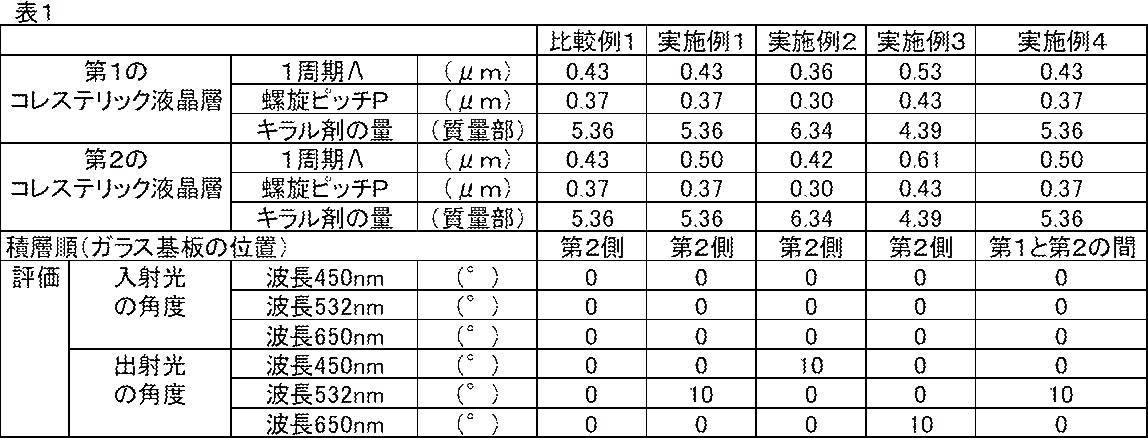
表1から、第1のコレステリック液晶層と第2のコレステリック液晶層の液晶配向パターンの1周期Λが同じである比較例1の場合には、いずれの波長の光も回折せずに透過することがわかる。これに対して、本発明の液晶回折素子は、選択反射波長の光を回折して透過し、それ以外の波長の光は回折せずに透過していることがわかる。すなわち、本発明の液晶回折素子は、波長選択性を有する透過型の回折素子であることがわかる。
以上の結果より、本発明の効果は明らかである。
以上の結果より、本発明の効果は明らかである。
透過型レンズなど、光学装置において光を屈折させる各種の用途に好適に利用可能である。
10 液晶回折素子
16 導光部材
18,22 第1のコレステリック液晶層
20,24 第2のコレステリック液晶層
21 コレステリック液晶層
30 支持体
32 配向膜
40 液晶化合物
40A 光学軸
60,80 露光装置
62,82 レーザ
64,84 光源
65 λ/2板
68,88,94 偏光ビームスプリッター
70A,70B,90A,90B ミラー
72A,72B,96 λ/4板
92 レンズ
RR 赤色の右円偏光
M レーザ光
MA,MB 光線
MP P偏光
MS S偏光
PO 直線偏光
PR 右円偏光
PL 左円偏光
Q 絶対位相
E 等位相面
L1,L2,L3,L4,L5,L6,L7 光
16 導光部材
18,22 第1のコレステリック液晶層
20,24 第2のコレステリック液晶層
21 コレステリック液晶層
30 支持体
32 配向膜
40 液晶化合物
40A 光学軸
60,80 露光装置
62,82 レーザ
64,84 光源
65 λ/2板
68,88,94 偏光ビームスプリッター
70A,70B,90A,90B ミラー
72A,72B,96 λ/4板
92 レンズ
RR 赤色の右円偏光
M レーザ光
MA,MB 光線
MP P偏光
MS S偏光
PO 直線偏光
PR 右円偏光
PL 左円偏光
Q 絶対位相
E 等位相面
L1,L2,L3,L4,L5,L6,L7 光
Claims (7)
- 液晶化合物をコレステリック配向させてなる第1のコレステリック液晶層、および、前記第1のコレステリック液晶層に積層された第2のコレステリック液晶層を有し、
前記第1のコレステリック液晶層および前記第2のコレステリック液晶層は、前記液晶化合物由来の光学軸の向きが面内の少なくとも一方向に沿って連続的に回転しながら変化している液晶配向パターンを有し、
前記第1のコレステリック液晶層の選択反射波長と、前記第2のコレステリック液晶層の選択反射波長とが同じであり、
前記液晶配向パターンにおける前記液晶化合物由来の光学軸の向きが面内で180°回転する長さを1周期とすると、前記第1のコレステリック液晶層の前記液晶配向パターンの1周期と、前記第2のコレステリック液晶層の前記液晶配向パターンの1周期とが異なっている液晶回折素子。 - 前記第1のコレステリック液晶層の前記液晶配向パターンの1周期が、前記第1のコレステリック液晶層の選択反射波長よりも小さく、
前記第2のコレステリック液晶層の前記液晶配向パターンの1周期が、前記第2のコレステリック液晶層の選択反射波長よりも小さい請求項1に記載の液晶回折素子。 - 前記第1のコレステリック液晶層の螺旋構造の捩れ方向と、前記第2のコレステリック液晶層の螺旋構造の捩れ方向とが同じである請求項1または2に記載の液晶回折素子。
- 前記第1のコレステリック液晶層の前記液晶配向パターンにおける前記一方向と、前記第2のコレステリック液晶層の前記液晶配向パターンにおける前記一方向とが一致している請求項1~3のいずれか一項に記載の液晶回折素子。
- 前記第1のコレステリック液晶層および前記第2のコレステリック液晶層の少なくとも一方の前記液晶配向パターンの1周期の長さが面内で異なる領域を有する請求項1~4のいずれか一項に記載の液晶回折素子。
- 前記第1のコレステリック液晶層および前記第2のコレステリック液晶層の前記液晶配向パターンが、前記液晶化合物由来の光学軸の向きが連続的に回転しながら変化する前記一方向を、内側から外側に向かう同心円状に有する、同心円状のパターンである請求項1~4のいずれか一項に記載の液晶回折素子。
- 請求項1~6のいずれか一項に記載の液晶回折素子を2以上有し、
各液晶回折素子の選択波長が互いに異なる積層回折素子。
Priority Applications (2)
| Application Number | Priority Date | Filing Date | Title |
|---|---|---|---|
| JP2021518355A JP7196290B2 (ja) | 2019-05-09 | 2020-04-24 | 液晶回折素子および積層回折素子 |
| US17/521,595 US11796880B2 (en) | 2019-05-09 | 2021-11-08 | Liquid crystal diffraction element and laminated diffraction element |
Applications Claiming Priority (2)
| Application Number | Priority Date | Filing Date | Title |
|---|---|---|---|
| JP2019088975 | 2019-05-09 | ||
| JP2019-088975 | 2019-05-09 |
Related Child Applications (1)
| Application Number | Title | Priority Date | Filing Date |
|---|---|---|---|
| US17/521,595 Continuation US11796880B2 (en) | 2019-05-09 | 2021-11-08 | Liquid crystal diffraction element and laminated diffraction element |
Publications (1)
| Publication Number | Publication Date |
|---|---|
| WO2020226080A1 true WO2020226080A1 (ja) | 2020-11-12 |
Family
ID=73050613
Family Applications (1)
| Application Number | Title | Priority Date | Filing Date |
|---|---|---|---|
| PCT/JP2020/017764 Ceased WO2020226080A1 (ja) | 2019-05-09 | 2020-04-24 | 液晶回折素子および積層回折素子 |
Country Status (3)
| Country | Link |
|---|---|
| US (1) | US11796880B2 (ja) |
| JP (1) | JP7196290B2 (ja) |
| WO (1) | WO2020226080A1 (ja) |
Cited By (3)
| Publication number | Priority date | Publication date | Assignee | Title |
|---|---|---|---|---|
| WO2023243295A1 (ja) * | 2022-06-15 | 2023-12-21 | 富士フイルム株式会社 | ファインダー光学系、ファインダー装置、および撮像装置 |
| WO2024204065A1 (ja) * | 2023-03-31 | 2024-10-03 | 富士フイルム株式会社 | 光学積層体、表示装置、センサー |
| WO2026053611A1 (ja) * | 2024-09-03 | 2026-03-12 | 学校法人関西学院 | 光学素子 |
Families Citing this family (2)
| Publication number | Priority date | Publication date | Assignee | Title |
|---|---|---|---|---|
| US11635669B1 (en) * | 2020-08-27 | 2023-04-25 | Meta Platforms Technologies, Llc | Optical device based on tunable polarization volume hologram |
| CN119200287B (zh) * | 2024-09-02 | 2025-12-09 | 南京大学 | 一种液晶图像识别器及其制备方法、图像识别装置 |
Citations (2)
| Publication number | Priority date | Publication date | Assignee | Title |
|---|---|---|---|---|
| US20180143438A1 (en) * | 2016-11-18 | 2018-05-24 | Magic Leap, Inc. | Multilayer liquid crystal diffractive gratings for redirecting light of wide incident angle ranges |
| US20180164627A1 (en) * | 2016-12-08 | 2018-06-14 | Magic Leap, Inc. | Diffractive devices based on cholesteric liquid crystal |
Family Cites Families (4)
| Publication number | Priority date | Publication date | Assignee | Title |
|---|---|---|---|---|
| AU2001249514A1 (en) * | 2000-03-27 | 2001-10-08 | California Institute Of Technology | Adjustable liquid crystal blazed grating deflector |
| JP6726110B2 (ja) | 2014-07-31 | 2020-07-22 | イマジンオプティクス・コーポレイション | 光学素子、及び回折光学素子 |
| US10564336B2 (en) | 2015-06-04 | 2020-02-18 | Osaka University | Reflective structure, device, and method for producing reflective structure |
| JP7015392B2 (ja) * | 2018-07-27 | 2022-02-15 | 富士フイルム株式会社 | 光学素子およびセンサー |
-
2020
- 2020-04-24 WO PCT/JP2020/017764 patent/WO2020226080A1/ja not_active Ceased
- 2020-04-24 JP JP2021518355A patent/JP7196290B2/ja active Active
-
2021
- 2021-11-08 US US17/521,595 patent/US11796880B2/en active Active
Patent Citations (2)
| Publication number | Priority date | Publication date | Assignee | Title |
|---|---|---|---|---|
| US20180143438A1 (en) * | 2016-11-18 | 2018-05-24 | Magic Leap, Inc. | Multilayer liquid crystal diffractive gratings for redirecting light of wide incident angle ranges |
| US20180164627A1 (en) * | 2016-12-08 | 2018-06-14 | Magic Leap, Inc. | Diffractive devices based on cholesteric liquid crystal |
Cited By (3)
| Publication number | Priority date | Publication date | Assignee | Title |
|---|---|---|---|---|
| WO2023243295A1 (ja) * | 2022-06-15 | 2023-12-21 | 富士フイルム株式会社 | ファインダー光学系、ファインダー装置、および撮像装置 |
| WO2024204065A1 (ja) * | 2023-03-31 | 2024-10-03 | 富士フイルム株式会社 | 光学積層体、表示装置、センサー |
| WO2026053611A1 (ja) * | 2024-09-03 | 2026-03-12 | 学校法人関西学院 | 光学素子 |
Also Published As
| Publication number | Publication date |
|---|---|
| US20220066075A1 (en) | 2022-03-03 |
| US11796880B2 (en) | 2023-10-24 |
| JPWO2020226080A1 (ja) | 2020-11-12 |
| JP7196290B2 (ja) | 2022-12-26 |
Similar Documents
| Publication | Publication Date | Title |
|---|---|---|
| JP7397954B2 (ja) | 光学素子および光偏向装置 | |
| JP7492001B2 (ja) | 透過型液晶回折素子 | |
| JP7196290B2 (ja) | 液晶回折素子および積層回折素子 | |
| JPWO2020122128A1 (ja) | 導光素子、画像表示装置およびセンシング装置 | |
| JPWO2020022513A1 (ja) | 光学素子の製造方法および光学素子 | |
| JP7367010B2 (ja) | 光学素子、波長選択フィルタおよびセンサー | |
| WO2020230556A1 (ja) | センサー | |
| WO2020226078A1 (ja) | 導光素子および画像表示装置 | |
| WO2021200228A1 (ja) | 導光素子 | |
| JP2023160888A (ja) | 光学素子および画像表示装置 | |
| JP7541104B2 (ja) | 透過型液晶回折素子 | |
| JP6931417B2 (ja) | 光学素子 | |
| CN117178212A (zh) | 液晶衍射元件、图像显示装置及头戴式显示器 | |
| JP2023076530A (ja) | 光偏向装置および光学装置 | |
| WO2023100916A1 (ja) | 光学素子および光学センサー | |
| WO2022264908A1 (ja) | 透過型液晶回折素子 | |
| WO2021182625A1 (ja) | 液晶層の製造方法 | |
| WO2021132063A1 (ja) | 画像表示装置およびarグラス | |
| JP7360481B2 (ja) | 光学素子および画像表示装置 | |
| WO2022239858A1 (ja) | 光学素子および光学センサー | |
| WO2021256413A1 (ja) | 光学異方性膜、光学素子、光学システム | |
| WO2021182627A1 (ja) | 液晶層の製造方法 | |
| JP7392160B2 (ja) | 透過型液晶回折素子 | |
| WO2025126979A1 (ja) | 光学素子 | |
| WO2021060474A1 (ja) | 光配向膜の形成方法および液晶層の形成方法 |
Legal Events
| Date | Code | Title | Description |
|---|---|---|---|
| 121 | Ep: the epo has been informed by wipo that ep was designated in this application |
Ref document number: 20802549 Country of ref document: EP Kind code of ref document: A1 |
|
| ENP | Entry into the national phase |
Ref document number: 2021518355 Country of ref document: JP Kind code of ref document: A |
|
| NENP | Non-entry into the national phase |
Ref country code: DE |
|
| 122 | Ep: pct application non-entry in european phase |
Ref document number: 20802549 Country of ref document: EP Kind code of ref document: A1 |