WO2020218436A1 - 通信制御方法 - Google Patents
通信制御方法 Download PDFInfo
- Publication number
- WO2020218436A1 WO2020218436A1 PCT/JP2020/017528 JP2020017528W WO2020218436A1 WO 2020218436 A1 WO2020218436 A1 WO 2020218436A1 JP 2020017528 W JP2020017528 W JP 2020017528W WO 2020218436 A1 WO2020218436 A1 WO 2020218436A1
- Authority
- WO
- WIPO (PCT)
- Prior art keywords
- base station
- message
- rrc
- deterioration
- timer
- Prior art date
- Legal status (The legal status is an assumption and is not a legal conclusion. Google has not performed a legal analysis and makes no representation as to the accuracy of the status listed.)
- Ceased
Links
Images





Classifications
-
- H—ELECTRICITY
- H04—ELECTRIC COMMUNICATION TECHNIQUE
- H04W—WIRELESS COMMUNICATION NETWORKS
- H04W76/00—Connection management
- H04W76/10—Connection setup
- H04W76/19—Connection re-establishment
-
- H—ELECTRICITY
- H04—ELECTRIC COMMUNICATION TECHNIQUE
- H04B—TRANSMISSION
- H04B17/00—Monitoring; Testing
- H04B17/30—Monitoring; Testing of propagation channels
- H04B17/309—Measuring or estimating channel quality parameters
-
- H—ELECTRICITY
- H04—ELECTRIC COMMUNICATION TECHNIQUE
- H04W—WIRELESS COMMUNICATION NETWORKS
- H04W24/00—Supervisory, monitoring or testing arrangements
- H04W24/10—Scheduling measurement reports ; Arrangements for measurement reports
-
- H—ELECTRICITY
- H04—ELECTRIC COMMUNICATION TECHNIQUE
- H04W—WIRELESS COMMUNICATION NETWORKS
- H04W76/00—Connection management
- H04W76/20—Manipulation of established connections
- H04W76/28—Discontinuous transmission [DTX]; Discontinuous reception [DRX]
-
- H—ELECTRICITY
- H04—ELECTRIC COMMUNICATION TECHNIQUE
- H04B—TRANSMISSION
- H04B17/00—Monitoring; Testing
- H04B17/20—Monitoring; Testing of receivers
- H04B17/24—Monitoring; Testing of receivers with feedback of measurements to the transmitter
-
- H—ELECTRICITY
- H04—ELECTRIC COMMUNICATION TECHNIQUE
- H04W—WIRELESS COMMUNICATION NETWORKS
- H04W76/00—Connection management
- H04W76/10—Connection setup
- H04W76/15—Setup of multiple wireless link connections
Definitions
- the present disclosure relates to a communication control method in a mobile communication system.
- 3GPP 3rd Generation Partnership Project
- a user device communicates with a master node and a secondary node at the same time
- dual connectivity wireless resources are allocated to the user device from both the master node and the secondary node, so that the user device can use high-speed and highly reliable communication.
- the dual connectivity communication ends and the user device terminates the dual connectivity communication.
- the RRC connection can be reestablished with other base stations.
- the wireless state between the user device and the master node can be improved after such deterioration of the wireless link, it is desired to introduce a mechanism that enables quick recovery of dual connectivity communication.
- the communication control method is a method for controlling dual connectivity communication in which the user device communicates at the same time as the master node and the secondary node.
- the user device detects the deterioration of the wireless link between the master node and the user device, and the user device detects the deterioration of the wireless link and sets a timer.
- the user device sends a message indicating the deterioration of the wireless link to the secondary node in response to the detection of the deterioration of the wireless link, and the user device causes the timer to expire. Includes processing to establish an RRC connection.
- DC dual connectivity
- the mobile communication system is a 5G system of 3GPP, but LTE may be applied to the mobile communication system at least partially.
- FIG. 1 is a diagram showing a configuration of a mobile communication system according to an embodiment.
- mobile communication systems include a user device (UE: User Equipment) 100, a 5G radio access network (NG-RAN: Next Generation Radio Access Network) 10, and a 5G core network (5GC: 5G). It has a Core Network) 20.
- UE User Equipment
- NG-RAN Next Generation Radio Access Network
- 5GC 5G core network
- the UE100 is a movable device.
- the UE 100 may be any device as long as it is a device used by the user.
- the UE 100 is a mobile phone terminal (including a smartphone), a tablet terminal, a notebook PC, a communication module (including a communication card or a chip set), a sensor or a device provided in the sensor, a vehicle or a device provided in the vehicle (Vehicle UE). ), Or a vehicle or a device (Aerial UE) provided on the vehicle.
- the NG-RAN 10 includes a base station (called "gNB” in a 5G system) 200.
- the gNB 200 is sometimes referred to as an NG-RAN node.
- the gNB 200s are connected to each other via the Xn interface, which is an interface between base stations.
- the gNB 200 manages one or more cells.
- the gNB 200 performs wireless communication with the UE 100 that has established a connection with its own cell.
- the gNB 200 has a radio resource management (RRM) function, a routing function for user data (hereinafter, simply referred to as “data”), and / or a measurement control function for mobility control / scheduling.
- RRM radio resource management
- Cell is used as a term to indicate the smallest unit of a wireless communication area.
- the term “cell” is also used to indicate a function or resource for wireless communication with the UE 100.
- One cell belongs to one carrier frequency.
- the gNB may be connected to the EPC (Evolved Packet Core), which is the LTE core network, or the LTE base station may be connected to the 5GC. Further, the LTE base station and gNB may be connected via an interface between base stations.
- EPC Evolved Packet Core
- 5GC20 includes AMF (Access and Mobility Management Function) and UPF (User Plane Function) 300.
- the AMF performs various mobility controls and the like for the UE 100.
- the AMF manages information on the area in which the UE 100 resides by communicating with the UE 100 using NAS (Non-Access Stratum) signaling.
- UPF controls data transfer.
- the AMF and UPF are connected to the gNB 200 via the NG interface, which is a base station-core network interface.
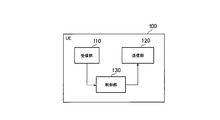
- FIG. 2 is a diagram showing the configuration of the UE 100 (user device).
- the UE 100 includes a receiving unit 110, a transmitting unit 120, and a control unit 130.
- the receiving unit 110 performs various receptions under the control of the control unit 130.
- the receiving unit 110 includes an antenna and a receiver.
- the receiver converts the radio signal received by the antenna into a baseband signal (received signal) and outputs it to the control unit 130.
- the transmission unit 120 performs various transmissions under the control of the control unit 130.
- the transmitter 120 includes an antenna and a transmitter.
- the transmitter converts the baseband signal (transmission signal) output by the control unit 130 into a radio signal and transmits it from the antenna.
- the control unit 130 performs various controls on the UE 100.
- the control unit 130 includes at least one processor and at least one memory electrically connected to the processor.
- the memory stores a program executed by the processor and information used for processing by the processor.
- the processor may include a baseband processor and a CPU (Central Processing Unit).
- the baseband processor modulates / demodulates and encodes / decodes the baseband signal.
- the CPU executes a program stored in the memory to perform various processes.
- FIG. 3 is a diagram showing the configuration of gNB200 (base station).
- the gNB 200 includes a transmission unit 210, a reception unit 220, a control unit 230, and a backhaul communication unit 240.
- the transmission unit 210 performs various transmissions under the control of the control unit 230.
- the transmitter 210 includes an antenna and a transmitter.
- the transmitter converts the baseband signal (transmission signal) output by the control unit 230 into a radio signal and transmits it from the antenna.
- the receiving unit 220 performs various receptions under the control of the control unit 230.
- the receiving unit 220 includes an antenna and a receiver.
- the receiver converts the radio signal received by the antenna into a baseband signal (received signal) and outputs it to the control unit 230.
- the control unit 230 performs various controls on the gNB 200.
- the control unit 230 includes at least one processor and at least one memory electrically connected to the processor.
- the memory stores a program executed by the processor and information used for processing by the processor.
- the processor may include a baseband processor and a CPU.
- the baseband processor modulates / demodulates and encodes / decodes the baseband signal.
- the CPU executes a program stored in the memory to perform various processes.
- the backhaul communication unit 240 is connected to an adjacent base station via an interface between base stations.
- the backhaul communication unit 240 is connected to the AMF / UPF 300 via the base station-core network interface.
- the gNB is composed of a CU (Central Unit) and a DU (Distributed Unit) (that is, the functions are divided), and both units may be connected by an F1 interface.
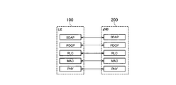
- FIG. 4 is a diagram showing a configuration of a protocol stack of a user plane wireless interface that handles data.
- the wireless interface protocol of the user plane includes a physical (PHY) layer, a MAC (Medium Access Control) layer, an RLC (Radio Link Control) layer, a PDCP (Packet Data Convergence Protocol) layer, and the like. It has an SDAP (Service Data Application Protocol) layer.
- PHY physical
- MAC Medium Access Control
- RLC Radio Link Control
- PDCP Packet Data Convergence Protocol
- SDAP Service Data Application Protocol
- the PHY layer performs coding / decoding, modulation / demodulation, antenna mapping / demapping, and resource mapping / demapping. Data and control information are transmitted between the PHY layer of the UE 100 and the PHY layer of the gNB 200 via a physical channel.
- the MAC layer performs data priority control, retransmission processing by hybrid ARQ (HARQ), random access procedure, and the like. Data and control information are transmitted between the MAC layer of the UE 100 and the MAC layer of the gNB 200 via a transport channel.
- the MAC layer of gNB200 includes a scheduler. The scheduler determines the transport format (transport block size, modulation / coding method (MCS)) of the upper and lower links and the resource block allocated to the UE 100.
- MCS modulation / coding method
- the RLC layer transmits data to the receiving RLC layer by using the functions of the MAC layer and the PHY layer. Data and control information are transmitted between the RLC layer of the UE 100 and the RLC layer of the gNB 200 via a logical channel.
- the PDCP layer performs header compression / decompression and encryption / decryption.
- the SDAP layer maps an IP flow, which is a unit for which the core network performs QoS control, and a wireless bearer, which is a unit for which AS (Access Stratum) controls QoS.
- IP flow which is a unit for which the core network performs QoS control
- wireless bearer which is a unit for which AS (Access Stratum) controls QoS.
- AS Access Stratum
- FIG. 5 is a diagram showing a configuration of a protocol stack of a wireless interface of a control plane that handles signaling (control signal).
- the protocol stack of the radio interface of the control plane has an RRC (Radio Resource Control) layer and a NAS (Non-Access Stratum) layer in place of the SDAP layer shown in FIG.
- RRC signaling for various settings is transmitted between the RRC layer of UE100 and the RRC layer of gNB200.
- the RRC layer controls logical channels, transport channels, and physical channels as radio bearers are established, reestablished, and released. If there is a connection (RRC connection) between the RRC of the UE 100 and the RRC of the gNB 200, the UE 100 is in RRC connected mode. If there is no connection (RRC connection) between the RRC of the UE 100 and the RRC of the gNB 200, the UE 100 is in RRC idle mode. Further, when the RRC connection is suspended, the UE 100 is in the RRC inactive mode.
- the NAS layer located above the RRC layer performs session management, mobility management, etc.
- NAS signaling is transmitted between the NAS layer of the UE 100 and the NAS layer of the AMF 300.
- the UE 100 has an application layer and the like in addition to the wireless interface protocol.
- DC dual connectivity
- MR-DCs Multi-RAT DCs
- Multi-connivity Multi-connivity
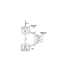
- a UE 100 having a plurality of transmitters / receivers is set to utilize resources provided by two different nodes (two different base stations).
- One base station provides NR access and the other base station provides E-UTRA (LTE) or NR access.
- the base station 200A may be an eNB or a gNB
- the base station 200B may be an eNB or a gNB.
- one base station 200A functions as a master node (MN), and the other base station 200B functions as a secondary node (SN).
- MN is a wireless access node that provides a control plane connection to the core network.
- the MN is sometimes referred to as the master base station.
- the SN is a wireless access node that does not have a control plane connection to the core network.
- the SN is sometimes referred to as a secondary base station.
- the MN and SN are connected via a network interface (inter-base station interface), and at least the MN is connected to the core network.
- FIG. 6 shows an example in which the inter-base station interface is an Xn interface, the inter-base station interface may be an X2 interface.
- the MN and SN send and receive various messages described later via the inter-base station interface.
- a group of serving cells that is a cell of MN and is set in UE100 is called a master cell group (MCG).
- MCG master cell group
- SCG secondary cell group
- radio resources are allocated to the UE 100 from both the MN (MCG) and the SN (SCG), and the UE 100 communicates with the MN and the SN at the same time, so that the UE 100 can use high-speed and highly reliable communication. Become.
- the UE 100 may have a single RRC state based on a single control plane connection to the MN's RRC and core network.
- Each of the MN and SN has an RRC entity capable of generating an RRC PDU (Protocol Data Unit) to be transmitted to the UE 100.
- RRC PDU Protocol Data Unit
- MCG link deterioration of the wireless link
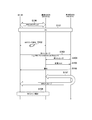
- FIG. 7 is a diagram showing the operation of the mobile communication system according to the first embodiment.
- step S100 the UE 100 has established an RRC connection with the base station 200A and is in the RRC connected mode.
- step S101 the UE 100 starts DC communication with the base station 200A and the base station 200B.
- the base station 200A may transmit an additional request (Addition Request) requesting the addition of the base station 200B for the DC to the base station 200B.
- the base station 200B may transmit an acknowledgment (Addition Request Ac) to the additional request (Addition Request) to the base station 200A in response to the reception of the additional request (Addition Request).
- the base station 200A may transmit an RRC message (for example, an RRC Reconfiguration message) including DC setting information to the UE 100 in response to receiving an acknowledgment (Addition Request Ac).
- the base station 200A may set this operation for the UE 100 having a function (MCG maintenance function via SCG) for performing the operation according to the first embodiment as a part of the DC setting.
- MCG maintenance function via SCG MCG maintenance function via SCG
- the base station 200A may set a threshold value for detecting the deterioration of the MCG link for the UE 100.
- the threshold value may be different from the threshold value for determining the trigger condition of the measurement report.
- the threshold is a threshold for radio status and may be for detecting signs of RLF.
- the base station 200A sets N times (M> N) as a threshold value for the UE 100.
- N N times
- the base station 200A functions as an MN
- the base station 200B functions as an SN
- at least one cell of the base station 200A is set in the UE 100 as an MCG
- at least one cell of the base station 200B is set in the UE 100 as an SCG.
- step S102 the UE 100 detects the deterioration of the MCG link.
- a wireless link refers to a layer 2 or lower wireless connection.
- Deterioration of MCG link means that RLF or its sign has occurred. For example, if the UE 100 does not recover within a certain period of time after a radio problem (for example, out of synchronization) occurs in the physical layer, or if a random access procedure failure and / or an RLC layer failure occurs, the UE 100 sets the RLF. Detect.
- the sign of RLF means that a failure occurs that is less than the detection threshold of RLF, although the detection threshold of RLF is not satisfied.
- a predetermined number of out-of-sync occurrences in the MCG link or a random access preamble resent a predetermined number of times in a random access procedure correspond to signs of RLF. These predetermined times may be set as a threshold value from the base station 200A.
- the UE 100 transmits a first message based on the deterioration of the MCG link to the base station 200B that functions as an SN. Specifically, when the UE 100 detects the RLF with the base station 200A functioning as the MN or a sign thereof, the UE 100 preferentially reselects the base station 200B (SCG) functioning as the SN. In this case, the UE 100 transmits an RRC Re-establishment Request message (first message) requesting the reestablishment of the RRC connection to the base station 200B (SCG). Alternatively, the first message may be an RRC Request Request message requesting the restoration of the RRC connection.
- the first message may be a message indicating the connection status of the MCG link, or may be a measurement report message.
- the first message may be the same as the first message according to the second embodiment described later.
- the UE 100 may include in the first message that it has a function (MCG maintenance function via SCG) that performs the operation according to the first embodiment, or that the operation is desired.
- MCG maintenance function via SCG MCG maintenance function via SCG
- the UE 100 that has detected the sign of RLF not only transmits the first message to the base station 200B, but also transmits the first message to the base station 200A. May be good.
- an RRC connection may be established between the UE 100 and the base station 200B based on the first message.
- the UE 100 may omit the transmission of the random access preamble (Msg1) to the base station 200B and the reception of the random access response (Msg2) from the base station 200B at the time of transmitting the RRC Re-establishment Request message.
- the UE 100 may include the C-RNTI (Cell-Radio Network Temporary Identifier) used in the SCG in the DC in the RRC Re-establishment Request message.
- C-RNTI Cell-Radio Network Temporary Identifier
- C-RNTI is assigned to the UE 100 from each of the base station 200A and the base station 200B, and the UE 100 includes an RRC Re-establishment Request message for the C-RNTI assigned from the base station 200B.
- the base station 200B In the base station 200B, the base station 200B (SN) provided the SCG to the source UE of the RRC Re-establishment Request message based on the C-RNTI included in the RRC Re-establishment Request message received from the UE 100. Identify that it is UE100. The UE 100 replaces or in addition to the C-RNTI assigned from the base station 200B, and sets the cell identifier of the primary / secondary cell (PSCell) included in the SCG provided by the base station 200B (SN) to the RRC Re-establishment. It may be included in the Request message.
- PSCell primary / secondary cell
- the base station 200B states that the UE 100 that has transmitted the RRC Re-establishment Request message including the cell identifier of the C-RNTI and / or PSCell assigned from the base station 200B has the ability of the MCG link holding function via the SCG. You may judge.
- step S104 the base station 200B that has received the first message transmits a second message used for restoring DC communication to the base station 200A.
- the second message may be a request message requesting the base station 200A to maintain the RRC connection between the base station 200A and the UE 100 or to maintain the DC state.
- the second message may be a notification message notifying the base station 200A that the base station 200B has received the RRC Re-establishment Request message from the UE 100 from the UE 100.
- the second message may be a transfer message including the RRC Re-establishment Request message received from the UE 100 by the base station 200B as a container.
- the second message may be the same as the second message according to the second embodiment described later.
- the second message includes each identifier of MN (base station 200A) and SN (base station 200B) on the inter-base station interface and a UE identifier on the inter-base station interface as information elements.
- the messages transmitted and received between the base station 200A and the base station 200B shall include these information elements.
- the second message may be a message requesting or proposing a split SRB, or a message including an information element requesting or proposing a split SRB.
- the split SRB is a branch in the MN in order to transmit the SRB not only in the MCG but also in the SCG.
- the second message may inform the type of SRB (SRB1, SRB2, or both) that is acceptable as a split SRB.
- step S105 the base station 200A that has received the second message transmits a response message to the second message to the base station 200B.
- the response message may be an acknowledgment (Ack) consenting to maintain the RRC connection between the base station 200A and the UE 100 or to maintain the DC state.
- Ack acknowledgment
- the response message may be a negative response (Nack) that refuses to maintain the RRC connection or DC state between the base station 200A and the UE 100.
- the base station 200A may transmit a Handover Request message for handing over the UE 100 to the base station 200B to the base station 200B.
- the response message may include information (Requested Split SRBs) indicating which SRB is to be the split SRB.
- the base station 200B which has received a negative response (Nack) from the base station 200A, may transmit an RRC Re-establishment message to the UE 100 in response to the RRC Re-establishment Request message received from the UE 100.
- the base station 200B receiving a negative response (Nack) from the base station 200A sends a message or information element to the UE 100 prompting the UE 100 to detect the RLF. Send. Then, the base station 200B may cause the UE 100 to perform Re-establishment.
- the message prompting the UE 100 to detect the RLF may be an RRC Re-establishment Reject message.
- MCG base station 200A
- step S106 the base station 200B that has received the acknowledgment (Ack) transmits a message to the UE 100 that the RRC connection with the base station 200A is maintained via the base station 200B (SCG link).
- the RRC connection between the UE 100 and the base station 200A is not physically via the MCG managed by the base station 200A. Therefore, the UE 100 may stop monitoring the RLF and other procedures for the base station 200A (MCG) (eg, PUCCH transmission, DRX operation, etc.). However, the UE 100 measures the radio state of the base station 200A.
- MCG base station 200A
- step S107 an RRC message is transmitted / received between the UE 100 and the base station 200A via the base station 200B while maintaining the RRC connection between the UE 100 and the base station 200A.
- the RRC message is a message sent and received in the RRC layer.
- the RRC message from the base station 200A to the UE 100 is transferred to the base station 200B via the inter-base station interface, and then transmitted from the base station 200B to the UE 100 on the signaling radio bearer (SRB) 3.
- SRB3 refers to a control radio bearer established between the UE 100 and the SN.
- the RRC message from the UE 100 to the base station 200A is transmitted to the base station 200B by the RRC container transmitted on the SRB3, and then transferred from the base station 200B to the base station 200A via the inter-base station interface.
- the RRC container transmitted on such SRB3 may be a dedicated RRC container that can be used only when the operation according to the first embodiment (that is, MCG connection via the SCG link) is active.
- the state of step S107 may be considered to be a state in which the UE 100 has an RRC connection with each of the base station 200A and the base station 200B.
- the RRC connection established between the UE 100 and the base station 200A may be suspended or deactivated.
- the UE 100 may be in the RRC inactive mode. Since the link state with the MCG is poor, if the UE 100 maintains the RRC connected mode, the UE 100 can detect the RLF. Therefore, the RRC connection between the UE 100 and the base station 200A may be interrupted.
- the RRC of the UE 100 connected to the MCG may be the master RRC (M-RRC), and the RRC of the UE 100 connected to the SCG may be the secondary RRC (S-RRC).
- the M-RRC of the UE 100 may give an instruction to select a cell to be connected to the S-RRC of the UE 100.
- the M-RRC of the UE 100 may set the list of candidate cells of the cell to be connected to the S-RRC in the S-RRC. Since it is difficult to control which cell the S-RRC may connect to, the M-RRC of the UE 100 specifies a cell to which the S-RRC of the UE 100 is connected. For example, in order to obtain diversity gain, the frequency of the connection destination cell may be different between M-RRC and S-RRC, or the S-RRC may select a cell different from the cell to which M-RRC is connected. It becomes possible to control the frequency.
- the UE 100 may transmit a measurement report to the base station 200A by the RRC container via the base station 200B.
- the measurement report includes the measurement result obtained by the UE 100 measuring the radio state for each cell.
- the base station 200A determines, for example, that the radio state between the UE 100 and the base station 200A has improved based on the measurement report from the UE 100 (step S108)
- the base station 200B is used as a DC by the RRC container.
- Control information for restoring the connection (RRC connection between the UE 100 and the base station 200) may be transmitted to the UE 100.
- This control information includes a non-conflict (Contention-free) random access preamble used for the random access procedure to the base station 200A and / or a radio setting used for wireless communication with the base station 200A.
- a message for re-requesting the RRC connection (for example, an RRC Re-Request message) via the base station 200B. ) May be transmitted to the base station 200A.
- the base station 200A may transmit a response message to this message to the UE 100 via the base station 200B.
- the response message may include information indicating that the DC will be restored based on the previous DC setting information.
- the UE 100 and the base station 200A restore the MCG link.
- the UE 100 may transmit a notification that the MCG link has been improved to the base station 200A by the RRC container via the base station 200B.
- the base station 200A may directly transmit the response to the notification from the UE 100 to the UE 100 via the MCG link, for example, by means of an RRC Configuration message.
- the base station 200A may transmit a response to the notification from the UE 100 to the UE 100 by the RRC container via the base station 200B.
- the base station 200A hands over the UE 100 to the base station 200B to the base station 200B.
- the RRC connection may be taken over.
- the DC ends, and the UE 100 communicates only with the base station 200B.
- the above fixed period may be set by a timer.
- the base station 200A may set a timer for the base station 200B.
- the base station 200B may start the timer when the first message is received from the UE 100 (step S103).
- the base station 200B may set (notify) a timer to the base station 200A.
- the base station 200A may start the timer when it receives the second message from the base station 200B (step S104) or when it transmits an acknowledgment (Ack) (step S105).
- the base station 200A may set a timer on the UE 100.
- the UE 100 may start the timer when it detects the deterioration of the MCG link. When the timer expires without the MCG link being restored, the UE 100 may automatically perform the handover to the base station 200B without receiving the handover instruction from the base station 200A.
- the UE 100 and the base via the base station 200B are maintained while maintaining the RRC connection between the UE 100 and the base station 200A. Send and receive RRC messages to and from station 200A.
- the base station 200A can perform various controls on the UE 100 via the SCG. Therefore, DC communication can be quickly restored when the wireless state of the MCG is improved.
- the UE 100 selects an appropriate cell by performing a cell reselection operation within a certain period of time, and transmits an RRC Re-establishment Request message.
- a cell reselection operation includes measurement of radio quality (RSRP, RSRQ, etc.) for each cell and evaluation of whether or not the measurement result satisfies the cell selection criterion.
- the base station 200B is functioning as an SN, such a cell reselection operation is unnecessary. Therefore, when the UE 100 detects the RLF with the base station 200A functioning as the MN or a sign thereof, the cell reselection operation may be omitted and an RRC Re-establishment Request message may be transmitted to the base station 200B.
- the UE 100 detects the RLF with the base station 200A functioning as the MN or its sign, if the SCG RLF (or SCG Radio program) with the base station 200B occurs, the UE 100 performs a cell reselection operation. You may go. On the other hand, the UE 100 may omit the cell reselection operation when the SCG RLF (or SCG Radio program) with the base station 200B has not occurred. When the cells of the base stations other than the base stations 200A and 200B are reselected by the cell reselection operation, the DC is terminated.
- the UE 100 may perform the omitted operation.
- FIG. 8 is a diagram showing the operation of the mobile communication system according to the second embodiment.
- step S200 the UE 100 has established an RRC connection with the base station 200A and is in the RRC connected mode.
- step S201 the UE 100 starts DC communication with the base station 200A and the base station 200B.
- the base station 200A may transmit an additional request (Addition Request) requesting the addition of the base station 200B for the DC to the base station 200B.
- the base station 200B may transmit an acknowledgment (Addition Request Ac) to the additional request (Addition Request) to the base station 200A in response to the reception of the additional request (Addition Request).
- the base station 200A may transmit an RRC message including DC setting information to the UE 100 in response to receiving an acknowledgment (Addition Request Ac) (step S202).
- the base station 200A functions as an MN
- the base station 200B functions as an SN
- at least one cell of the base station 200A is set in the UE 100 as an MCG
- at least one cell of the base station 200B is set in the UE 100 as an SCG.
- the base station 200A may set a threshold value for detecting the deterioration of the MCG link for the UE 100.
- the threshold value may be different from the threshold value for determining the trigger condition of the measurement report.
- the threshold is a threshold for radio status and may be for detecting signs of RLF.
- the base station 200A sets N times (M> N) as a threshold value for the UE 100.
- the UE 100 can detect the possibility of RLF at an early stage before the occurrence of RLF with MCG.
- the base station 200A may transmit the setting information to be used after the Role Change to the UE 100 in advance. Specifically, the base station 200A transmits a plurality of RRC settings to the UE 100.
- the first RRC setting among these RRC settings is the setting information for immediate use for the MCG link, and becomes active when the UE 100 is set.
- at least one second RRC setting is setting information to be used after the Role Change, and is in a standby state (inactive) when it is set in the UE 100.
- the base station 200A may include a plurality of RRC settings in one RRC Configuration message and collectively transmit the plurality of RRC settings to the UE 100. Alternatively, the base station 200A may transmit the first RRC setting to the UE 100 first, and then additionally transmit the second RRC setting to the UE 100. The base station 200A may delete any one of the plurality of RRC settings by designating the UE 100. Each of the plurality of RRC settings may be associated with a cell identifier. The base station 200A may transmit a plurality of sets of RRC settings and cell identifiers to the UE 100. For example, the UE 100 properly uses the RRC setting by activating the corresponding RRC setting for each cell that becomes the MCG.
- step S203 the UE 100 detects the deterioration of the MCG link.
- deterioration of the MCG link means that RLF or a sign thereof has occurred.
- the UE 100 detects an RLF when a radio problem (for example, out of synchronization) occurs in the physical layer and does not spread within a certain period of time, or when a random access procedure failure or an RLC layer failure occurs.
- a radio problem for example, out of synchronization
- the sign of RLF means that a failure occurs that is less than the detection threshold of RLF, although the detection threshold of RLF is not satisfied.
- a predetermined number of out-of-sync occurrences in the MCG link or a random access preamble resent a predetermined number of times in a random access procedure correspond to signs of RLF. These predetermined times may be set as a threshold value from the base station 200A.
- the UE 100 that has detected the sign of RLF in step S204 may send a message notifying the possibility of RLF to the base station 200A.
- This message may be a message different from the measurement report, or may be a request message requesting Role Change.
- the UE 100 may transmit a message to the base station 200A by using the SRB (SRB1) associated with the MAC entity for MCG.
- the base station 200A may perform the Role Change (step S207) based on the reception of the message notifying the possibility of RLF.
- step S205 the UE 100 transmits a first message based on the deterioration of the MCG link to the base station 200B that functions as an SN.
- the UE 100 that has detected the sign of RLF may transmit a message to the base station 200A in step S204 and may transmit a first message to the base station 200B in step S205.
- the first message may be a message indicating that the UE 100 has detected RLF with the base station 200A (MCG link) or a sign thereof. Such a message may be called an M-RLF information message.
- the first message may be a measurement report message.
- the UE 100 transmits an M-RLF information message or a measurement report message to the base station 200B by using the SRB (SRB3) associated with the MAC entity for SCG.
- the first message may include at least one of an information element indicating the type of failure (T310 expiration, random access failure, or reaching the RLC retransmission upper limit) and an information element indicating the measurement result of the radio state.
- step S206 the base station 200B transmits a second message to the base station 200A based on the first message received from the UE 100.
- the second message may be a notification message indicating that the RLF of the MCG link or a sign thereof has been detected, or may be a request message for the base station 200B to become an MN.
- the second message may include at least one of PDCP Change Indication, which is an information element indicating whether PDCP data recovery is necessary, and a container for carrying the information element of RRC.
- PDCP Change Indication which is an information element indicating whether PDCP data recovery is necessary
- step S207 the base station 200A and the base station 200B perform a Role Change.
- the base station 200A bases a response message (Ack or Nack) to this Role Change request message. It may be transmitted to the station 200B.
- the base station 200A may transmit a Role Change request message to the base station 200B based on the message received from the UE 100 in step S204 or the second message received from the base station 200B in step S206. ..
- the Role Change request message may include various setting information necessary for the base station 200B to become an MN.
- the base station 200B that has received the Role Change request message may transmit a response message (Ack or Nack) to the Role Change request message to the base station 200A.
- the base station 200A is changed to SN (step S208), and the base station 200B is changed to MN (step S209).
- At least one of the base station 200A and the base station 200B may transmit a message indicating that the Role Change has been performed to the UE 100 (step S210, step S211).
- the message indicating that the Role Change has been performed may include at least one of the cell identifier of each cell included in the new MCG and the cell identifier of each cell included in the SCG.
- the UE 100 confirms that the Role Change has been performed based on the message received in step S210 and / or step S211.
- the second RRC setting was on standby. Activate the RRC settings for. After that, the UE 100 starts applying the second RRC setting.
- the UE 100 uses the cell identifier of the cell that has become the new MCG among the plurality of second RRC settings. Activate the second RRC setting associated with. After that, the UE 100 may discard the other second RRC settings or keep it in the standby state. Whether to discard or retain may be determined by the setting from the base station 200A (step S202).
- the UE 100 may activate the second RRC setting that has been on standby, triggered by a condition different from the condition that the message was received in step S210 and / or step S211.
- the UE 100 may activate the second RRC setting that has been on standby, triggered by the transmission of the message in step S204 or the transmission of the message in step S205.
- the UE 100 can send and receive data to and from the base station 200A.
- the base station 200B functioning as the MN transmits a release message to the base station 200A.
- the base station 200B may release the base station 200A that functions as an SN.
- the DC ends, and the UE 100 communicates only with the base station 200B.
- the setting method for this fixed period is the same as that in the first embodiment.
- the base station 200B which has become a new MN, can control the UE 100 while maintaining the base station 200A as an SN. Therefore, DC communication can be quickly restored when the wireless state of the base station 200A is improved.
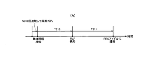
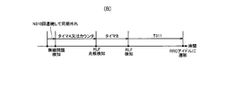
- the UE 100 detects an out-of-sync state (out-of-sync) N310 times in a row, it detects a radio problem (radio problem).
- the UE 100 starts a predetermined timer T310.
- the UE 100 stops the timer T310 when the synchronization state (in-sync) is continuously detected N311 times.
- the timer T310 expires, the UE 100 detects the RLF, starts the timer T311 and starts the cell reselection operation (connection reestablishment process). Then, when the timer T311 expires without succeeding in reestablishing the connection, the UE 100 shifts to the RRC idle mode.
- the UE 100 detects the sign of the MCG RLF when the timer A expires, and transmits the above-mentioned first message to the base station 200B.
- the UE 100 increments the counter each time it detects a radio problem, and when the counter value reaches a threshold value, it detects a sign of MCG RLF and transmits the above-mentioned first message to the base station 200B.
- the UE 100 detects the out-of-sync state (out-of-sync) N310 times in succession, it detects the radio problem once.
- the UE 100 continuously detects the synchronization state (in-sync) N311 times (timer T310 stops) and then continuously detects the out-of-synchronization state (out-of-sync) N310 times, a wireless problem occurs. Is detected once more. In this way, the counter value is incremented.
- the UE 100 may reset the counter value if the radio problem does not occur for a certain period of time.
- the threshold value of this counter value can be set as appropriate.
- the counter may be a counter that counts the out-of-sync state (out-of-sync).
- the threshold value of this counter may be larger or smaller than the value of N310.
- the UE 100 may reset this counter value when it detects the synchronization state (in-sync). It is assumed that the cycle in which the UE 100 detects the out-of-synchronization state (out-of-sync) is Tout, the cycle in which the UE 100 detects the synchronization state (in-sync) is Tin, and each of Tout and Tin is a constant time. ..
- the threshold value Out of the counter that counts the above-mentioned out-of-synchronization state (out-of-sync) may be set so as to satisfy Nout ⁇ Tout ⁇ N311 ⁇ Tin. If this formula is satisfied, the UE 100 can detect the sign of RLF before detecting the synchronization state (in-sync) N311 times, that is, before the expiration of the timer T310. The UE 100 sets the timing to start counting the out-of-sync state (out-of-sync) to be the first of N310 times out-of-sync state (out-of-sync), which is a condition for detecting a radio problem in FIGS. 9A and 9B. It may be the timing when the (first) out-of-synchronization state is detected.
- the value (threshold value) of the timer A and the threshold value of the counter may be set from the base station 200A or 200B to the UE 100.
- the value of the period during which the radio problem does not occur (the above-mentioned "fixed period") may be set from the base station 200A or 200B to the UE 100.
- the UE 100 may detect the sign of MCG RLF by combining the timer A and the counter.
- the UE 100 detects the sign of RLF, and when the above-mentioned first message is transmitted to the base station 200B, the timer B is started.
- the UE 100 suspends the start of the RLF detection or connection reestablishment process (RRC Restabrishment procedure) while the timer B is operating.
- RRC Restabrishment procedure RRC Restabrishment procedure
- the network (base stations 200A and 200B) side performs the operations as described in the first and second embodiments described above.
- instructions to the UE 100 can be transmitted from the network.
- the UE 100 can wait for an instruction from the network side.
- the UE 100 may stop the timer B when it receives an instruction from the network side while the timer B is operating. While the timer B is operating, the UE 100 does not detect the RLF even if the timer T310 expires, and does not execute the connection reestablishment process.
- the UE 100 When the timer B expires, the UE 100 performs the reserved operation. That is, the UE 100 detects the RLF and starts the connection reestablishment process.
- the value (threshold value) of the timer B may be set from the base station 200A or 200B to the UE 100.
- the timer B is a timer that operates in parallel with the timer T310.
- the timer B may not be required by partially changing the handling of the timer T310 and resetting (restarting) the timer T310 when the sign of RLF is detected and the first message is transmitted.
- the UE 100 starts a timer in response to detecting deterioration of the MCG link (that is, RLF or a sign thereof), and improves (recovers) the radio state of the MCG link until the timer expires. I explained an example of waiting for.
- the base station 200A which is an MN, can give an instruction to the UE 100 (for example, a handover instruction) while the timer is operating, it is possible to grasp whether or not the timer is operating in the UE 100. desired. However, it is difficult for the base station 200A to grasp when the UE 100 starts the timer.
- FIG. 10 is a diagram showing the operation of the mobile communication system according to this modified example.
- the operation according to this modification relates to a method for controlling DC communication in which the UE 100 communicates at the same time as the base station 200A (MN) and the base station 200B (SN).
- MN base station 200A
- SN base station 200B
- steps S300 to S303 are the same as steps S100 to S102 in the first embodiment.
- the base station 200A may set a timer value in the UE 100 that determines the time for waiting for an instruction from the base station 200A after detecting the deterioration of the wireless link between the base station 200A and the UE 100. .. This timer value may be set individually for each UE by the RRC Reconfiguration message, or may be set by broadcasting by the SIB. Further, the base station 200A may set the UE 100 to allow the transmission of the first message.
- step S304 the UE 100 starts a timer that determines the time for waiting for the instruction from the base station 200A.
- the value of the timer may be set from the base station 200A in step S302, or may be a preset value specified in the specifications.
- the start timing of the timer may be the timing at which the deterioration of the MCG link is detected, or the timing at which the first message is transmitted.
- step S305 the UE 100 transmits a first message indicating deterioration of the wireless link to the base station 200B.
- This first message may be the same as the first message described in the above-described embodiment, and is, for example, a message indicating that RLF with the base station 200A (MCG link) or a sign thereof has been detected.
- MCG link MCG link
- Such a message may be referred to as an MCG fiber indication message.
- the UE 100 includes timing information indicating the start timing of the timer in step S304 in the first message.
- the timing information may be represented by the system frame number (SFN) of the base station 200A corresponding to the start timing of the timer.
- the timing information may be represented by an absolute time corresponding to the start timing of the timer. This absolute time may be an absolute time obtained by GNSS (Global Navigation Satellite System) of UE 100.
- GNSS Global Navigation Satellite System
- the base station 200B which is an SN, receives the first message from the UE 100.
- the base station 200B transmits a second message corresponding to the first message from the UE 100 to the base station 200A.
- This second message may be the same as the second message described in the above-described embodiment, and may be, for example, a transfer message including the contents of the first message received from the UE 100 by the base station 200B as a container. Good. That is, the timing information included in the first message by the UE 100 is transferred from the base station 200B to the base station 200A.
- the base station 200A When the base station 200A receives the second message from the base station 200B, the base station 200A stays in the base station 200A for a period of time (that is, until the timer expires) based on the timing information included in the received second message. Period) is determined. The base station 200A determines that the instruction to the UE 100 can be transmitted within this period.
- the base station 200A may determine that the instruction to the UE 100 cannot be transmitted, and may determine that the instruction message is not transmitted. Further, the base station 200A may consider that the UE 100 has detected the MCG RLF, or may discard the UE context of the UE 100.
- the UE context may be discarded when the timer expires, or after a certain period of time has elapsed from the time when the timer expires.
- the fixed period may be, for example, a timing at which it can be determined that the UE context acquisition request from another base station is not received. Specifically, the timing may be the timing at which the timer (T311) for determining the failure of the RRC Restabrishment has expired and the UE 100 has transitioned to the IDLE mode.
- the base station 200A can grasp the timer start timing in the UE 100.
- the base station 200A receives the second message.
- the base station 200A can accurately grasp the timer start timing in the UE 100 even if there is a delay before receiving the signal.
- the UE 100 does not include the timing information in the first message, and the base station 200B includes the timing information in the second message. It may be included in the message. Specifically, the base station 200B considers the timing at which the first message is received from the UE 100 as the timer start timing in the UE 100, and includes information indicating the timing at which the first message is received from the UE 100 as timing information in the second message.
- Modification 3 of the first and second embodiments In the above-described embodiment, when the MCG link is restored after the UE 100 detects the deterioration of the MCG link (that is, RLF or a sign thereof), the UE 100 notifies the base station 200B that the MCG link has been improved (recovered). An example of transmitting to the base station 200A via the above has been described. In this modification, the details of such an operation will be described.
- FIG. 11 is a diagram showing the operation of the mobile communication system according to this modified example.
- the operation according to this modification relates to a method for controlling DC communication in which the UE 100 communicates at the same time as the base station 200A (MN) and the base station 200B (SN).
- MN base station 200A
- SN base station 200B
- steps S400 to S406 are the same as the above-mentioned modification 2.
- the timer described in the above-mentioned modification example 2 is not essential in this modification example.
- the UE 100 detects the recovery of the wireless link (MCG link) with the base station 200A. Specifically, the UE 100 detects that the radio state of the MCG link has been restored as follows. For example, the UE 100 has a wireless state of the MCG link when the received power or reception quality of the reference signal received from the MCG exceeds the threshold value, or when the received power or reception quality exceeds the threshold value for a certain period of time. Detects recovery. Alternatively, the UE 100 may detect the recovery of the wireless state of the MCG link when the number of times that the synchronous state (in-sync) of the MCG link is continuously detected exceeds the threshold value. These thresholds may be set from the base station 200A to the UE 100 (for example, set in step S402).
- step S408 the UE 100 transmits a third message indicating that the MCG link has been improved (recovered) to the base station 200A.
- a third message may be referred to as an MCG Recovered Indication message.
- the UE 100 may send a third message indicating that the MCG link has been improved (recovered) to the base station 200B.
- the base station 200B may transmit a fourth message corresponding to the third message from the UE 100 to the base station 200A (step S410).
- the fourth message may be a transfer message including the contents of the third message received from the UE 100 by the base station 200B as a container.
- the UE 100 may transmit the third message indicating the recovery of the wireless link. That is, as one of the conditions under which the third message can be transmitted, a condition that the time is within a predetermined time after the first message is transmitted may be defined.
- a condition that the transmission permission of the first message is set from the base station 200A may be defined. Further, as one of the conditions under which the third message can be transmitted, a condition that the transmission permission of the third message is set from the base station 200A may be defined. As one of the conditions under which the third message can be transmitted, a condition that the timer described in the above-described second modification is in operation may be defined.
- the base station 200A grasps that the MCG link has been improved (recovered) based on the third message received from the UE 100 in step S408 or the fourth message received from the base station 200B in step S410, and wirelessly communicates with the UE 100. To resume.
- This modified example relates to an operation for making an addition or modification to the base station 200B.
- the addition to the base station 200B means that the base station 200B is added as an SN in order to start DC communication when the UE 100 is connected to the base station 200A.
- the addition to base station 200B is sometimes referred to as SCG Addition.
- the change to the base station 200B means changing the SN of the UE 100 that has already started DC communication from another base station to the base station 200B.
- the changes to base station 200B are sometimes referred to as SCG Change.
- FIG. 12 is a diagram showing the operation of the mobile communication system according to this modified example.
- the operation according to this modification relates to a method for controlling DC communication in which the UE 100 communicates at the same time as the base station 200A (MN) and the base station 200B (SN).
- MN base station 200A
- SN base station 200B
- step S500 the UE 100 has established an RRC connection with the base station 200A and is in the RRC connected mode.
- the base station 200A transmits an RRC Reconfiguration message to the UE 100 for making additions or changes to the base station 200B.
- the RRC Reconfiguration message contains information for setting a non-competitive-based PRACH (Physical Random Access Channel) resource.
- This non-competitive-based PRACH resource is a PRACH resource reserved at base station 200B to make additions or changes to base station 200B.
- the UE 100 After receiving the RRC Reconfiguration message, the UE 100 starts a random access procedure for connecting to the base station 200B.
- step S502 before the UE 100 connects to the base station 200B, the UE 100 detects deterioration of the wireless link (MCG Fairure) between the base station 200A and the UE 100.
- MCG Fairure the wireless link
- step S503 the UE 100 starts the RRC reestablishment process for the base station 200B in response to detecting the deterioration of the radio link between the base station 200A and the UE 100, and sets the random access preamble (Msg1) to the base station 200B. Send to.
- the UE 100 transmits a random access preamble to the base station 200B by using the non-competitive-based PRACH resource set by the RRC Configuration message.
- step S504 the base station 200B transmits a random access response (Msg2) to the UE 100 in response to receiving the random access preamble from the UE 100.
- Msg2 random access response
- step S505 the UE 100 transmits an RRC re-establishment request (RRC Re-establishment Request) message to the base station 200B.
- RRC Re-establishment Request RRC Re-establishment Request
- the RRC reestablishment request message corresponds to Msg3.
- the UE 100 uses the non-competitive-based PRACH resource to perform the base station. Send a random access preamble to 200B.
- the UE 100 and the base station 200B can more reliably complete the RRC reestablishment process.
- the UE 100 may transmit the first message described above using the Spirit SRB1.
- the Split SRB1 is a signaling radio bearer branched at the base station 200A, and the base station 200B is interposed between the base station 200A and the UE 100.
- the UE 100 may transmit the above-mentioned first message using the SRB3.
- the base station 200B functioning as the SN may be in charge of controlling the UE 100, or may be instructed by the MN (base station 200A) via the Xn interface.
- the base station 200A or 200B that has received the above-mentioned first message may transmit a handover instruction to the UE 100.
- This handover instruction may be a conditional handover instruction.
- At least a part of the operation according to the first embodiment and at least a part of the operation according to the second embodiment may be combined and carried out.
- At least a part of the operation according to the first embodiment and at least a part of the operation according to the second embodiment may be applied to carrier aggregation (CA).
- CA carrier aggregation
- MN and MCG are read as primary cells (PCell)
- SCell secondary cells
- the UE 100 may perform DC communication with the base station and other UEs. Specifically, the UE 100 performs simultaneous communication with the base station and other UEs via the Uu interface with the base station and the PC5 interface (side link) with the other UEs. Under such an assumption, the above-mentioned M-RRC may be used as an RRC for a base station (Uu), and the above-mentioned S-RRC may be used as an RRC for another UE (PC5).
- Uu base station
- PC5 another UE
- a program that causes a computer to execute each process performed by the UE 100 or the gNB 200 may be provided.
- the program may be recorded on a computer-readable medium.
- Computer-readable media can be used to install programs on a computer.
- the computer-readable medium on which the program is recorded may be a non-transient recording medium.
- the non-transient recording medium is not particularly limited, but may be, for example, a recording medium such as a CD-ROM or a DVD-ROM.
- a circuit that executes each process performed by the UE 100 or the gNB 200 may be integrated, and at least a part of the UE 100 or the gNB 200 may be configured as a semiconductor integrated circuit (chipset, SoC).
Landscapes
- Engineering & Computer Science (AREA)
- Computer Networks & Wireless Communication (AREA)
- Signal Processing (AREA)
- Quality & Reliability (AREA)
- Physics & Mathematics (AREA)
- Electromagnetism (AREA)
- Mobile Radio Communication Systems (AREA)
Abstract
一実施形態に係る通信制御方法は、ユーザ装置がマスタノード及びセカンダリノードと同時に通信するデュアルコネクティビティ通信を制御するための方法である。前記通信制御方法は、前記ユーザ装置が、前記マスタノードと前記ユーザ装置との間の無線リンクの劣化を検知することと、前記ユーザ装置が、前記無線リンクの劣化の検知に応じて、前記マスタノードからの指示を待つためのタイマを開始させることと、前記ユーザ装置が、前記無線リンクの劣化の検知に応じて、前記無線リンクの劣化を示すメッセージを前記セカンダリノードに送信し、前記メッセージは、前記セカンダリノードから前記マスタノードに転送されることとを含む。前記メッセージは、前記タイマの開始タイミングを示すタイミング情報を含む。
Description
本開示は、移動通信システムにおける通信制御方法に関する。
従来、移動通信システムの標準化プロジェクトである3GPP(3rd Generation Partnership Project)において、ユーザ装置がマスタノード及びセカンダリノードと同時に通信するデュアルコネクティビティが規定されている。デュアルコネクティビティは、マスタノード及びセカンダリノードの両方からユーザ装置に無線リソースが割り当てられるため、高速且つ高信頼性の通信をユーザ装置が利用可能になる。
このようなデュアルコネクティビティの通信中に、ユーザ装置がマスタノードとの無線リンクの劣化、例えば、無線リンク障害(RLF:Radio Link Failure)を検知した場合、デュアルコネクティビティ通信が終了し、ユーザ装置は、RRC接続を他の基地局と再確立しうる。しかしながら、このような無線リンクの劣化後、ユーザ装置とマスタノードとの間の無線状態が改善しうるため、デュアルコネクティビティ通信を速やかに復旧可能とする仕組みを導入することが望まれる。
第1の態様に係る通信制御方法は、ユーザ装置がマスタノード及びセカンダリノードと同時に通信するデュアルコネクティビティ通信を制御するための方法である。前記通信制御方法は、前記ユーザ装置が、前記マスタノードと前記ユーザ装置との間の無線リンクの劣化を検知することと、前記ユーザ装置が、前記無線リンクの劣化の検知に応じて、タイマを開始させることと、前記ユーザ装置が、前記無線リンクの劣化の検知に応じて、前記無線リンクの劣化を示すメッセージを前記セカンダリノードに送信することと、前記ユーザ装置が、前記タイマが満了した場合に、RRC接続を確立するための処理を行うこととを含む。
図面を参照しながら、実施形態に係る移動通信システムについて説明する。図面の記載において、同一又は類似の部分には同一又は類似の符号を付している。
(移動通信システム)
まず、一実施形態に係る移動通信システムの構成について説明する。一実施形態に係る移動通信システムは3GPPの5Gシステムであるが、移動通信システムには、LTEが少なくとも部分的に適用されてもよい。
まず、一実施形態に係る移動通信システムの構成について説明する。一実施形態に係る移動通信システムは3GPPの5Gシステムであるが、移動通信システムには、LTEが少なくとも部分的に適用されてもよい。
図1は、一実施形態に係る移動通信システムの構成を示す図である。
図1に示すように、移動通信システムは、ユーザ装置(UE:User Equipment)100と、5Gの無線アクセスネットワーク(NG-RAN:Next Generation Radio Access Network)10と、5Gのコアネットワーク(5GC:5G Core Network)20とを有する。
UE100は、移動可能な装置である。UE100は、ユーザにより利用される装置であればどのような装置であってもよい。例えば、UE100は、携帯電話端末(スマートフォンを含む)、タブレット端末、ノートPC、通信モジュール(通信カード又はチップセットを含む)、センサ若しくはセンサに設けられる装置、車両若しくは車両に設けられる装置(Vehicle UE)、又は飛行体若しくは飛行体に設けられる装置(Aerial UE)である。
NG-RAN10は、基地局(5Gシステムにおいて「gNB」と呼ばれる)200を含む。gNB200は、NG-RANノードと呼ばれることもある。gNB200は、基地局間インターフェイスであるXnインターフェイスを介して相互に接続される。gNB200は、1又は複数のセルを管理する。gNB200は、自セルとの接続を確立したUE100との無線通信を行う。gNB200は、無線リソース管理(RRM)機能、ユーザデータ(以下、単に「データ」という)のルーティング機能、及び/又はモビリティ制御・スケジューリングのための測定制御機能等を有する。「セル」は、無線通信エリアの最小単位を示す用語として用いられる。「セル」は、UE100との無線通信を行う機能又はリソースを示す用語としても用いられる。1つのセルは1つのキャリア周波数に属する。
なお、gNBがLTEのコアネットワークであるEPC(Evolved Packet Core)に接続されてもよいし、LTEの基地局が5GCに接続されてもよい。また、LTEの基地局とgNBとが基地局間インターフェイスを介して接続されてもよい。
5GC20は、AMF(Access and Mobility Management Function)及びUPF(User Plane Function)300を含む。AMFは、UE100に対する各種モビリティ制御等を行う。AMFは、NAS(Non-Access Stratum)シグナリングを用いてUE100と通信することにより、UE100が在圏するエリアの情報を管理する。UPFは、データの転送制御を行う。AMF及びUPFは、基地局-コアネットワーク間インターフェイスであるNGインターフェイスを介してgNB200と接続される。
図2は、UE100(ユーザ装置)の構成を示す図である。
図2に示すように、UE100は、受信部110、送信部120、及び制御部130を備える。
受信部110は、制御部130の制御下で各種の受信を行う。受信部110は、アンテナ及び受信機を含む。受信機は、アンテナが受信する無線信号をベースバンド信号(受信信号)に変換して制御部130に出力する。
送信部120は、制御部130の制御下で各種の送信を行う。送信部120は、アンテナ及び送信機を含む。送信機は、制御部130が出力するベースバンド信号(送信信号)を無線信号に変換してアンテナから送信する。
制御部130は、UE100における各種の制御を行う。制御部130は、少なくとも1つのプロセッサと、プロセッサと電気的に接続された少なくとも1つのメモリと、を含む。メモリは、プロセッサにより実行されるプログラム、及びプロセッサによる処理に用いられる情報を記憶する。プロセッサは、ベースバンドプロセッサと、CPU(Central Processing Unit)と、を含んでもよい。ベースバンドプロセッサは、ベースバンド信号の変調・復調及び符号化・復号等を行う。CPUは、メモリに記憶されるプログラムを実行して各種の処理を行う。
図3は、gNB200(基地局)の構成を示す図である。
図3に示すように、gNB200は、送信部210、受信部220、制御部230、及びバックホール通信部240を備える。
送信部210は、制御部230の制御下で各種の送信を行う。送信部210は、アンテナ及び送信機を含む。送信機は、制御部230が出力するベースバンド信号(送信信号)を無線信号に変換してアンテナから送信する。
受信部220は、制御部230の制御下で各種の受信を行う。受信部220は、アンテナ及び受信機を含む。受信機は、アンテナが受信する無線信号をベースバンド信号(受信信号)に変換して制御部230に出力する。
制御部230は、gNB200における各種の制御を行う。制御部230は、少なくとも1つのプロセッサと、プロセッサと電気的に接続された少なくとも1つのメモリと、を含む。メモリは、プロセッサにより実行されるプログラム、及びプロセッサによる処理に用いられる情報を記憶する。プロセッサは、ベースバンドプロセッサと、CPUと、を含んでもよい。ベースバンドプロセッサは、ベースバンド信号の変調・復調及び符号化・復号等を行う。CPUは、メモリに記憶されるプログラムを実行して各種の処理を行う。
バックホール通信部240は、基地局間インターフェイスを介して隣接基地局と接続される。バックホール通信部240は、基地局-コアネットワーク間インターフェイスを介してAMF/UPF300と接続される。なお、gNBは、CU(Central Unit)とDU(Distributed Unit)とで構成され(すなわち、機能分割され)、両ユニット間がF1インターフェイスで接続されてもよい。
図4は、データを取り扱うユーザプレーンの無線インターフェイスのプロトコルスタックの構成を示す図である。
図4に示すように、ユーザプレーンの無線インターフェイスプロトコルは、物理(PHY)レイヤと、MAC(Medium Access Control)レイヤと、RLC(Radio Link Control)レイヤと、PDCP(Packet Data Convergence Protocol)レイヤと、SDAP(Service Data Adaptation Protocol)レイヤとを有する。
PHYレイヤは、符号化・復号、変調・復調、アンテナマッピング・デマッピング、及びリソースマッピング・デマッピングを行う。UE100のPHYレイヤとgNB200のPHYレイヤとの間では、物理チャネルを介してデータ及び制御情報が伝送される。
MACレイヤは、データの優先制御、ハイブリッドARQ(HARQ)による再送処理、及びランダムアクセスプロシージャ等を行う。UE100のMACレイヤとgNB200のMACレイヤとの間では、トランスポートチャネルを介してデータ及び制御情報が伝送される。gNB200のMACレイヤはスケジューラを含む。スケジューラは、上下リンクのトランスポートフォーマット(トランスポートブロックサイズ、変調・符号化方式(MCS))及びUE100への割当リソースブロックを決定する。
RLCレイヤは、MACレイヤ及びPHYレイヤの機能を利用してデータを受信側のRLCレイヤに伝送する。UE100のRLCレイヤとgNB200のRLCレイヤとの間では、論理チャネルを介してデータ及び制御情報が伝送される。
PDCPレイヤは、ヘッダ圧縮・伸張、及び暗号化・復号化を行う。
SDAPレイヤは、コアネットワークがQoS制御を行う単位であるIPフローと、AS(Access Stratum)がQoS制御を行う単位である無線ベアラと、のマッピングを行う。なお、RANがEPCに接続される場合は、SDAPが無くてもよい。
図5は、シグナリング(制御信号)を取り扱う制御プレーンの無線インターフェイスのプロトコルスタックの構成を示す図である。
図5に示すように、制御プレーンの無線インターフェイスのプロトコルスタックは、図4に示したSDAPレイヤに代えて、RRC(Radio Resource Control)レイヤ及びNAS(Non-Access Stratum)レイヤを有する。
UE100のRRCレイヤとgNB200のRRCレイヤとの間では、各種設定のためのRRCシグナリングが伝送される。RRCレイヤは、無線ベアラの確立、再確立及び解放に応じて、論理チャネル、トランスポートチャネル、及び物理チャネルを制御する。UE100のRRCとgNB200のRRCとの間に接続(RRC接続)がある場合、UE100はRRCコネクティッドモードにある。UE100のRRCとgNB200のRRCとの間に接続(RRC接続)がない場合、UE100はRRCアイドルモードにある。また、RRC接続が中断(サスペンド)されている場合、UE100はRRCインアクティブモードにある。
RRCレイヤの上位に位置するNASレイヤは、セッション管理及びモビリティ管理等を行う。UE100のNASレイヤとAMF300のNASレイヤとの間では、NASシグナリングが伝送される。
なお、UE100は、無線インターフェイスのプロトコル以外にアプリケーションレイヤ等を有する。
(デュアルコネクティビティ)
次に、デュアルコネクティビティ(DC)の概要について説明する。以下において、NRアクセスを含むDCを主として想定する。このようなDCは、MR-DC(Multi-RAT DC)又はMulti-connectivityと呼ばれることがある。図6は、DCの一例を示す図である。
次に、デュアルコネクティビティ(DC)の概要について説明する。以下において、NRアクセスを含むDCを主として想定する。このようなDCは、MR-DC(Multi-RAT DC)又はMulti-connectivityと呼ばれることがある。図6は、DCの一例を示す図である。
図6に示すように、DCにおいて、複数の送受信機を有するUE100は、2つの異なるノード(2つの異なる基地局)によって提供されるリソースを利用するように設定される。一方の基地局はNRアクセスを提供し、他方の基地局はE-UTRA(LTE)又はNRアクセスを提供する。図6の例において、基地局200AはeNB又はgNBであり、基地局200BはeNB又はgNBであってもよい。
また、一方の基地局200Aがマスタノード(MN)として機能し、他方の基地局200Bがセカンダリノード(SN)として機能する。MNは、コアネットワークへの制御プレーン接続を提供する無線アクセスノードである。MNは、マスタ基地局と呼ばれることがある。SNは、コアネットワークへの制御プレーン接続を持たない無線アクセスノードである。SNは、セカンダリ基地局と呼ばれることがある。
MNとSNとはネットワークインターフェース(基地局間インターフェイス)を介して接続され、少なくともMNはコアネットワークに接続される。図6において、基地局間インターフェイスがXnインターフェイスである一例を示しているが、基地局間インターフェイスがX2インターフェイスであってもよい。MN及びSNは、基地局間インターフェイスを介して、後述する各種のメッセージを送受信する。
MNのセルであって、UE100に設定されるサービングセルのグループは、マスタセルグループ(MCG)と呼ばれる。一方、SNのセルであって、UE100に設定されるサービングセルのグループは、セカンダリセルグループ(SCG)と呼ばれる。
DCによれば、MN(MCG)及びSN(SCG)の両方からUE100に無線リソースが割り当てられ、UE100がMN及びSNと同時に通信することにより、高速且つ高信頼性の通信をUE100が利用可能になる。
UE100は、MNのRRC及びコアネットワークへの単一の制御プレーン接続に基づいて単一のRRC状態を有してもよい。MN及びSNのそれぞれは、UE100に送信されるべきRRC PDU(Protocol Data Unit)を生成可能なRRCエンティティを有する。
(第1実施形態)
次に、上述したような移動通信システムの構成を前提として、第1実施形態に係る移動通信システムの動作について説明する。
次に、上述したような移動通信システムの構成を前提として、第1実施形態に係る移動通信システムの動作について説明する。
第1実施形態において、DC通信の開始後、基地局200AとUE100との間の無線リンク(以下、「MCGリンク」と呼ぶ)の劣化が検知された場合を想定する。この場合において、MNとして機能する基地局200Aが、SNとして機能する基地局200B経由でUE100を制御することにより、DC通信を速やかに復旧可能とする一例について説明する。
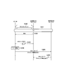
図7は、第1実施形態に係る移動通信システムの動作を示す図である。
図7に示すように、ステップS100において、UE100は、基地局200AとのRRC接続を確立しており、RRCコネクティッドモードにある。
ステップS101において、UE100は、DC通信を基地局200A及び基地局200Bと開始する。
ここで、基地局200Aは、DCのために基地局200Bの追加を要求する追加要求(Addition Request)を基地局200Bに送信してもよい。基地局200Bは、追加要求(Addition Request)の受信に応じて、追加要求(Addition Request)への肯定応答(Addition Request Ack)を基地局200Aに送信してもよい。基地局200Aは、肯定応答(Addition Request Ack)の受信に応じて、DCの設定情報を含むRRCメッセージ(例えば、RRC Reconfigurationメッセージ)をUE100に送信してもよい。
基地局200Aは、DC設定の一部として、第1実施形態に係る動作を行う機能(SCG経由のMCG維持機能)を有するUE100に対してこの動作の設定を行ってもよい。
基地局200Aは、UE100に対して、MCGリンクの劣化を検知するための閾値を設定してもよい。閾値は、測定報告のトリガ条件を定めるための閾値とは異なるものであってもよい。閾値は、無線状態に関する閾値であって、RLFの兆候を検知するためのものであってもよい。例えば、UE100が、RLC再送がM回に達したらRLFを検知するという前提下において、基地局200Aは、UE100に対して、閾値としてN回(M>N)を設定しておく。これにより、UE100は、MCGとのRLF発生前に、RLFの可能性を早期に検知できる。
その結果、基地局200AはMNとして機能し、基地局200BはSNとして機能する。また、基地局200Aの少なくとも1つのセルがMCGとしてUE100に設定され、基地局200Bの少なくとも1つのセルがSCGとしてUE100に設定される。
ステップS102において、UE100は、MCGリンクの劣化を検知する。無線リンクとは、レイヤ2以下の無線接続をいう。
MCGリンクの劣化とは、RLF又はその兆候が発生したことをいう。例えば、UE100は、物理レイヤにおいて無線問題(例えば、同期外れ)が発生してから一定時間内に復旧しない場合、又はランダムアクセスプロシージャの障害、及び/又はRLCレイヤの障害が発生した場合、RLFを検知する。
RLFの兆候とは、RLFの検知閾値が満たされないものの、RLFの検知閾値未満の障害が発生したことをいう。例えば、MCGリンクにおいて同期外れが一定時間内に所定回数発生したこと、又はランダムアクセスプロシージャにおいてランダムアクセスプリアンブルを所定回数だけ再送したことがRLFの兆候に相当する。これらの所定回数は、基地局200Aから閾値として設定されてもよい。
なお、基地局200AとUE100との間のRLF又はその兆候が発生した場合、UE100はRLF又はその兆候を検知できるものの、基地局200AはRLF又はその兆候を検知できないと考えられる。
ステップS103において、UE100は、MCGリンクの劣化に基づく第1メッセージを、SNとして機能する基地局200Bに送信する。具体的には、UE100は、MNとして機能する基地局200AとのRLF又はその兆候を検知すると、SNとして機能する基地局200B(SCG)を優先して再選択する。この場合、UE100は、基地局200B(SCG)に対して、RRC接続の再確立を要求するRRC Re-establishment Requestメッセージ(第1メッセージ)を送信する。或いは、第1メッセージは、RRC接続の復旧を要求するRRC Resume Requestメッセージであってもよい。或いは、第1メッセージは、MCGリンクの接続状況を示すメッセージであってもよいし、測定報告メッセージであってもよい。第1メッセージは、後述する第2実施形態に係る第1メッセージと同じであってもよい。UE100は、第1メッセージに、第1実施形態に係る動作を行う機能(SCG経由のMCG維持機能)を有する旨もしくは当該動作を希望する旨を含めてよい。
第1メッセージがMCGリンクの接続状況を示すメッセージである場合、RLFの兆候を検知したUE100は、第1メッセージを基地局200Bに送信するだけではなく、第1メッセージを基地局200Aに送信してもよい。
第1メッセージがRRC Re-establishment Requestメッセージ又はRRC Resume Requestメッセージである場合、第1メッセージに基づいてUE100と基地局200Bとの間にRRC接続が確立されてもよい。
ここで、UE100は、RRC Re-establishment Requestメッセージの送信時において、基地局200Bへのランダムアクセスプリアンブル(Msg1)の送信、及び基地局200Bからのランダムアクセス応答(Msg2)の受信を省略してもよい。UE100は、RRC Re-establishment Requestメッセージに、DC中にSCGで使っていたC-RNTI(Cell-Radio Network Temporary Identifier)を含めてもよい。具体的には、基地局200A及び基地局200BのそれぞれからUE100にC-RNTIが割り当てられており、UE100は、基地局200Bから割り当てられたC-RNTIをRRC Re-establishment Requestメッセージを含める。基地局200Bは、UE100から受信したRRC Re-establishment Requestメッセージに含まれるC-RNTIに基づいて、RRC Re-establishment Requestメッセージの送信元UEが、基地局200B(SN)がSCGを提供していたUE100であることを特定する。UE100は、基地局200Bから割り当てられたC-RNTIに代えて又は加えて、基地局200B(SN)が提供していたSCGに含まれるプライマリ・セカンダリセル(PSCell)のセル識別子をRRC Re-establishment Requestメッセージに含めてもよい。基地局200Bは、基地局200Bから割り当てられたC-RNTI及び/又はPSCellのセル識別子を含むRRC Re-establishment Requestメッセージを送信したUE100がSCG経由のMCGリンク保持機能の能力を有していると判断してもよい。
ステップS104において、第1メッセージを受信した基地局200Bは、DC通信を復旧するために用いる第2メッセージを基地局200Aに送信する。
第2メッセージは、基地局200AとUE100との間のRRC接続を維持すること又はDC状態を維持することを基地局200Aに要求する要求メッセージであってもよい。第2メッセージは、基地局200BがUE100からRRC Re-establishment RequestメッセージをUE100から受信したことを基地局200Aに通知する通知メッセージであってもよい。第2メッセージは、基地局200BがUE100から受信したRRC Re-establishment Requestメッセージをコンテナとして含む転送メッセージであってもよい。第2メッセージは、後述する第2実施形態に係る第2メッセージと同じであってもよい。
第2メッセージは、基地局間インターフェイス上でのMN(基地局200A)及びSN(基地局200B)のそれぞれの識別子と、基地局間インターフェイス上でのUE識別子とを情報要素として含む。以下の第1実施形態及び第2実施形態において、基地局200Aと基地局200Bとの間で送受信されるメッセージには、これらの情報要素が含まれるものとする。
第2メッセージは、スプリット(Sprit) SRBを要求もしくは提案するメッセージであってもよいし、スプリットSRBを要求もしくは提案する情報要素を含むメッセージであってもよい。スプリットSRBとは、SRBをMCGだけでなくSCGでも送信するためにMNにおいて分岐されるものである。第2メッセージは、スプリットSRBとして受け入れ可能なSRBの種別(SRB1、SRB2、又はそれらの両方)を通知してもよい。
ステップS105において、第2メッセージを受信した基地局200Aは、第2メッセージに対する応答メッセージを基地局200Bに送信する。
応答メッセージは、基地局200AとUE100との間のRRC接続を維持すること又はDC状態を維持することを承諾する肯定応答(Ack)であってもよい。
応答メッセージは、基地局200AとUE100との間のRRC接続を維持すること又はDC状態を維持することを拒否する否定応答(Nack)であってもよい。この場合、基地局200Aは、UE100を基地局200BにハンドオーバするためのHandover Requestメッセージを基地局200Bに送信してもよい。
応答メッセージは、どのSRBをスプリットSRBにするかを示す情報(Requested Split SRBs)を含んでもよい。
基地局200Aから否定応答(Nack)を受信した基地局200Bは、UE100から受信したRRC Re-establishment Requestメッセージに対してRRC Re-establishmentメッセージをUE100に送信してもよい。或いは、UE100が基地局200AとのRLFを検知していない場合、基地局200Aから否定応答(Nack)を受信した基地局200Bは、UE100にRLFを検知するように促すメッセージ又は情報要素をUE100に送信する。そして、基地局200Bは、UE100にRe-establishmentを行わせてもよい。UE100にRLFを検知するように促すメッセージは、RRC Re-establishment Rejectメッセージであってもよい。UE100は、RLFを検知するように促すメッセージを受信した場合、基地局200A(MCG)との通信を継続し、RLFのモニタを実施する。
以下において、基地局200Bが受信した応答メッセージが肯定応答(Ack)であると仮定して説明を進める。
ステップS106において、肯定応答(Ack)を受信した基地局200Bは、基地局200B(SCGリンク)経由で基地局200AとのRRC接続が維持される旨を通知するメッセージをUE100に送信する。この状態において、UE100と基地局200Aとの間のRRC接続は物理的には基地局200Aが管理するMCGを介していない。そのため、UE100は、基地局200A(MCG)に対するRLFのモニタリング及びその他のプロシージャ(例えば、PUCCHの送信、DRX動作など)は停止してもよい。但し、UE100は、基地局200Aに対する無線状態の測定は実施する。
ステップS107において、UE100と基地局200Aとの間のRRC接続を維持しつつ、基地局200Bを介してUE100と基地局200Aとの間でRRCメッセージを送受信する。RRCメッセージとは、RRCレイヤにおいて送受信されるメッセージをいう。
ここで、基地局200AからUE100へのRRCメッセージは、基地局間インターフェイス経由で基地局200Bに転送された後、基地局200BからUE100に対して、シグナリング無線ベアラ(SRB)3上で伝送されるRRCコンテナによって送信される。SRB3とは、UE100とSNとの間で確立される制御用の無線ベアラをいう。
UE100から基地局200AへのRRCメッセージは、SRB3上で伝送されるRRCコンテナによって基地局200Bに送信された後、基地局間インターフェイス経由で基地局200Bから基地局200Aに転送される。
このようなSRB3上で伝送されるRRCコンテナは、第1実施形態に係る動作(すなわち、SCGリンク経由のMCG接続)がアクティブな場合のみ使用可能な専用のRRCコンテナであってもよい。
ステップS107の状態は、UE100が基地局200A及び基地局200BのそれぞれとRRC接続を有する状態であると考えてもよい。この場合、UE100と基地局200Aとの間で確立されているRRC接続が中断(サスペンド)又は非アクティブ化されていてもよい。UE100は、RRCインアクティブモードであってもよい。MCGとのリンク状態が悪い状態であるため、UE100がRRCコネクティッドモードを維持すると、UE100がRLFを検知しうる。そのため、UE100と基地局200Aとの間のRRC接続が中断されていてもよい。
なお、MCGと接続しているUE100のRRCをマスタRRC(M-RRC)、SCGと接続しているUE100のRRCをセカンダリRRC(S-RRC)としてもよい。UE100のM-RRCは、UE100のS-RRCの接続先とするセルを選択させる指示を行ってもよい。ここで、UE100のM-RRCは、S-RRCの接続先とするセルの候補セルのリストをS-RRCに設定してもよい。S-RRCがどのセルと接続してもよいとすると制御しにくいため、UE100のM-RRCは、UE100のS-RRCの接続先とするセルを指定する。例えば、ダイバーシティゲインを得るために、M-RRCとS-RRCとで接続先セルの周波数を別にしたり、M-RRCが接続しているセルとは別のセルをS-RRCに選択させたりする制御が可能になる。
UE100は、基地局200Bを介して、基地局200Aに対してRRCコンテナにより測定報告を送信してもよい。測定報告は、UE100がセルごとに無線状態を測定して得た測定結果を含む。基地局200Aは、UE100からの測定報告に基づいて、例えばUE100と基地局200Aとの間の無線状態が改善したと判定した場合(ステップS108)、基地局200Bを介して、RRCコンテナにより、DC接続(UE100と基地局200との間のRRC接続)を復旧させるための制御情報をUE100に送信してもよい。この制御情報は、基地局200Aへのランダムアクセスプロシージャに用いる非競合(Contention-free)ランダムアクセスプリアンブル、及び/又は基地局200Aとの無線通信に用いる無線設定などを含む。
UE100は、例えばUE100と基地局200Aとの間の無線状態が改善したと判定した場合(ステップS108)、基地局200Bを介して、RRC接続を再要求するためのメッセージ(例えばRRC Re-Requestメッセージ)を基地局200Aに送信してもよい。基地局200Aは、基地局200Bを介して、このメッセージに対する応答メッセージをUE100に送信してもよい。応答メッセージには、前回のDCの設定情報を基にDCを復旧することを示す情報を含めてもよい。
ステップS108において、UE100及び基地局200Aは、MCGリンクを復旧させる。ここで、UE100は、MCGリンクが改善した旨の通知を、基地局200Bを介して、RRCコンテナにより基地局200Aに送信してもよい。基地局200Aは、UE100からの通知に対する応答を、MCGリンク経由で例えばRRC ReconfigurationメッセージによりUE100に直接的に送信してもよい。或いは、基地局200Aは、UE100からの通知に対する応答を、基地局200Bを介してRRCコンテナによりUE100に送信してもよい。
一方、一定期間が経過してもMCGリンクの無線状態が改善しない場合(つまり、MCGリンクを再確立できない場合)、基地局200Aは、基地局200Bに対してUE100をハンドオーバし、基地局200BにRRC接続を引き継いでもよい。この場合、DCが終了し、UE100は基地局200Bとのみ通信を行う。
上記の一定期間は、タイマによって設定されてもよい。基地局200Aが基地局200Bにタイマを設定してもよい。基地局200Bは、UE100から第1メッセージを受信した際(ステップS103)にタイマを開始させてもよい。基地局200Bが基地局200Aにタイマを設定(通知)してもよい。基地局200Aは、基地局200Bから第2メッセージを受信した際(ステップS104)又は肯定応答(Ack)を送信する際(ステップS105)に、タイマを開始させてもよい。基地局200AがUE100にタイマを設定してもよい。UE100は、MCGリンクの劣化を検知した際に、タイマを開始させてもよい。UE100は、MCGリンクが復旧することなくタイマが満了した場合、基地局200Aからのハンドオーバ指示を受信しなくても、自動的に基地局200Bにハンドオーバを行ってもよい。
第1実施形態によれば、DC通信の開始後、MCGリンクの劣化が検知された際に、UE100と基地局200Aとの間のRRC接続を維持しつつ、基地局200Bを介してUE100と基地局200Aとの間でRRCメッセージを送受信する。これにより、MCGリンクのRLFが発生した場合であっても、基地局200AがSCG経由でUE100に対して各種の制御を実施可能である。そのため、MCGの無線状態が改善した場合にDC通信を速やかに復旧できる。
(第1実施形態の変更例)
上述した第1実施形態において、UE100が、MNとして機能する基地局200AとのRLF又はその兆候を検知すると、SNとして機能する基地局200B(SCG)を優先して再選択する場合を想定した。その場合に、UE100が、基地局200B(SCG)に対して、RRC接続の再確立を要求するRRC Re-establishment Requestメッセージ(第1メッセージ)を送信する一例について上述した第1実施形態において説明した。
上述した第1実施形態において、UE100が、MNとして機能する基地局200AとのRLF又はその兆候を検知すると、SNとして機能する基地局200B(SCG)を優先して再選択する場合を想定した。その場合に、UE100が、基地局200B(SCG)に対して、RRC接続の再確立を要求するRRC Re-establishment Requestメッセージ(第1メッセージ)を送信する一例について上述した第1実施形態において説明した。
一般的に、RLFが検知された場合、UE100は、一定期間内でセル再選択動作を行うことにより、適切なセルを選択してRRC Re-establishment Requestメッセージを送信する。このようなセル再選択動作は、セルごとの無線品質(RSRP、RSRQ等)の測定と、測定結果がセル選択基準を満たすか否かの評価とを含む。
しかしながら、基地局200BがSNとして機能している場合、このようなセル再選択動作は不要である。このため、UE100は、MNとして機能する基地局200AとのRLF又はその兆候を検知すると、セル再選択動作を省略して、RRC Re-establishment Requestメッセージを基地局200Bに送信してもよい。
但し、UE100は、MNとして機能する基地局200AとのRLF又はその兆候を検知した際に、基地局200BとのSCG RLF (もしくはSCGのRadio problem)が発生している場合はセル再選択動作を行ってもよい。一方、UE100は、基地局200BとのSCG RLF (もしくはSCGのRadio problem)が発生していない場合はセル再選択動作を省略してもよい。なお、セル再選択動作により、基地局200A及び200B以外の基地局のセルが再選択される場合、DCが終了することになる。
UE100は、このようなセル選択動作を省略する動作の実行許可が基地局200A又は200Bから設定されている場合、当該省略動作を行うとしてもよい。
(第2実施形態)
次に、第2実施形態に係る移動通信システムの動作について、第1実施形態との相違点を主として説明する。
次に、第2実施形態に係る移動通信システムの動作について、第1実施形態との相違点を主として説明する。
第2実施形態において、DC通信の開始後、MCGリンクの劣化が検知された場合、基地局200Aと基地局200Bとの間でMN及びSNの役割を入れ替えること(以下、適宜「Role Change」と呼ぶ)により、DC通信を速やかに復旧可能とする一例について説明する。
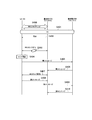
図8は、第2実施形態に係る移動通信システムの動作を示す図である。
図8に示すように、ステップS200において、UE100は、基地局200AとのRRC接続を確立しており、RRCコネクティッドモードにある。
ステップS201において、UE100は、DC通信を基地局200A及び基地局200Bと開始する。
ここで、基地局200Aは、DCのために基地局200Bの追加を要求する追加要求(Addition Request)を基地局200Bに送信してもよい。基地局200Bは、追加要求(Addition Request)の受信に応じて、追加要求(Addition Request)への肯定応答(Addition Request Ack)を基地局200Aに送信してもよい。
基地局200Aは、肯定応答(Addition Request Ack)の受信に応じて、DCの設定情報を含むRRCメッセージをUE100に送信してもよい(ステップS202)。
その結果、基地局200AはMNとして機能し、基地局200BはSNとして機能する。また、基地局200Aの少なくとも1つのセルがMCGとしてUE100に設定され、基地局200Bの少なくとも1つのセルがSCGとしてUE100に設定される。
ステップS202において、基地局200Aは、UE100に対して、MCGリンクの劣化を検知するための閾値を設定してもよい。閾値は、測定報告のトリガ条件を定めるための閾値とは異なるものであってもよい。閾値は、無線状態に関する閾値であって、RLFの兆候を検知するためのものであってもよい。例えば、RLC再送がM回に達したらRLFを検知するという前提下において、基地局200Aは、UE100に対して、閾値としてN回(M>N)を設定しておく。これにより、UE100は、MCGとのRLF発生前に、RLFの可能性を早期に検知できる。
ステップS202において、基地局200Aは、Role Change後に用いるべき設定情報を予めUE100に送信してもよい。具体的には、基地局200Aは、UE100に対して複数のRRC設定を送信する。これらのRRC設定のうち第1のRRC設定は、MCGリンク用に即座に使うための設定情報であって、UE100に設定された時点でアクティブになる。これらのRRC設定のうち、少なくとも1つの第2のRRC設定は、Role Change後に用いるべき設定情報であって、UE100に設定された時点ではスタンバイ状態(非アクティブ)にある。
基地局200Aは、複数のRRC設定を1つのRRC Reconfigurationメッセージに含めて、複数のRRC設定をまとめてUE100に送信してもよい。或いは、基地局200Aは、第1のRRC設定を先にUE100に送信し、その後、第2のRRC設定を追加的にUE100に送信してもよい。基地局200Aは、複数のRRC設定のうちいずれかをUE100に指定して削除してもよい。複数のRRC設定のそれぞれは、セル識別子と紐づいていてもよい。基地局200Aは、RRC設定とセル識別子との複数のセットをUE100に送信してもよい。例えば、UE100は、MCGになるセルごとに、対応するRRC設定をアクティブにすることでRRC設定を使い分ける。
ステップS203において、UE100は、MCGリンクの劣化を検知する。
上述したように、MCGリンクの劣化とは、RLF又はその兆候が発生したことをいう。例えば、UE100は、物理レイヤにおいて無線問題(例えば、同期外れ)が発生してから一定時間内に普及しない場合、又はランダムアクセスプロシージャの障害、RLCレイヤの障害が発生した場合、RLFを検知する。
RLFの兆候とは、RLFの検知閾値が満たされないものの、RLFの検知閾値未満の障害が発生したことをいう。例えば、MCGリンクにおいて同期外れが一定時間内に所定回数発生したこと、又はランダムアクセスプロシージャにおいてランダムアクセスプリアンブルを所定回数だけ再送したことがRLFの兆候に相当する。これらの所定回数は、基地局200Aから閾値として設定されてもよい。
なお、基地局200AとUE100との間のRLF又はその兆候が発生した場合、UE100はRLF又はその兆候を検知できるものの、基地局200AはRLF又はその兆候を検知できないと考えられる。
ステップS204において、RLFの兆候を検知したUE100は、RLFの可能性を通知するメッセージを基地局200Aに送信してもよい。このメッセージは、測定報告とは異なるメッセージであってもよいし、Role Changeを要求する要求メッセージであってもよい。UE100は、MCG用のMACエンティティに紐づいたSRB(SRB1)を用いて、メッセージを基地局200Aに送信してもよい。基地局200Aは、RLFの可能性を通知するメッセージの受信に基づいて、Role Change(ステップS207)を行ってもよい。
ステップS205において、UE100は、MCGリンクの劣化に基づく第1メッセージを、SNとして機能する基地局200Bに送信する。RLFの兆候を検知したUE100は、ステップS204でメッセージを基地局200Aに送信するとともに、ステップS205で第1メッセージを基地局200Bに送信してもよい。
第1メッセージは、UE100が基地局200A(MCGリンク)とのRLF又はその兆候を検知したことを示すメッセージであってもよい。このようなメッセージは、M-RLF informationメッセージと呼ばれてもよい。第1メッセージは、測定報告メッセージであってもよい。UE100は、基地局200Bに対して、SCG用のMACエンティティに紐づいたSRB(SRB3)を用いて、M-RLF informationメッセージ又は測定報告メッセージを送信する。
第1メッセージは、障害の種別(T310満了、ランダムアクセス失敗、RLC再送上限到達のいずれか)を示す情報要素と、無線状態の測定結果を示す情報要素とのうち少なくとも1つを含んでもよい。
ステップS206において、基地局200Bは、UE100から受信した第1メッセージに基づいて、第2メッセージを基地局200Aに送信する。
第2メッセージは、MCGリンクのRLF又はその兆候を検知したことを示す通知メッセージであってもよいし、基地局200BがMNになるための要求メッセージであってもよい。
第2メッセージは、PDCPデータリカバリが必要か否かを示す情報要素であるPDCP Change Indicationと、RRCの情報要素を運ぶためのコンテナとのうち少なくとも1つを含んでもよい。
ステップS207において、基地局200A及び基地局200Bは、Role Changeを行う。
第2メッセージが、基地局200BがMNになるための要求メッセージ(Role Change要求メッセージ)である場合、ステップS207において、基地局200Aは、このRole Change要求メッセージに対する応答メッセージ(Ack又はNack)を基地局200Bに送信してもよい。
或いは、ステップS207において、基地局200Aは、ステップS204でUE100から受信したメッセージ又はステップS206で基地局200Bから受信した第2メッセージに基づいて、Role Change要求メッセージを基地局200Bに送信してもよい。Role Change要求メッセージは、基地局200BがMNになるために必要な各種の設定情報を含んでもよい。Role Change要求メッセージを受信した基地局200Bは、Role Change要求メッセージに対する応答メッセージ(Ack又はNack)を基地局200Aに送信してもよい。
その結果、基地局200AがSNに変更(ステップS208)されるとともに、基地局200BがMNに変更(ステップS209)される。
基地局200A及び基地局200Bの少なくとも一方は、Role Changeが行われたことを示すメッセージをUE100に送信してもよい(ステップS210、ステップS211)。Role Changeが行われたことを示すメッセージは、新たなMCGに含まれる各セルのセル識別子及びSCGに含まれる各セルのセル識別子のうち少なくとも一方を含んでもよい。
UE100は、ステップS210及び/又はステップS211で受信したメッセージに基づいて、Role Changeが行われたことを確認する。
Role Changeが行われたことを確認したUE100は、ステップS202で基地局200Aから複数のRRC設定(第1のRRC設定及び第2のRRC設定)を受信していた場合、スタンバイしていた第2のRRC設定をアクティブ化する。その後、UE100は、第2のRRC設定の適用を開始する。第2のRRC設定が複数存在し、各第2のRRC設定がセル識別子と紐付けられている場合、UE100は、複数の第2のRRC設定のうち、新たにMCGになったセルのセル識別子と紐付けられた第2のRRC設定をアクティブ化する。その後、UE100は、その他の第2のRRC設定を破棄するか又はスタンバイ状態のまま保持してもよい。破棄するか又は保持するかは、基地局200Aからの設定(ステップS202)により定められてもよい。
なお、UE100は、ステップS210及び/又はステップS211でメッセージを受信したこととは異なる条件をトリガとして、スタンバイしていた第2のRRC設定をアクティブ化してもよい。例えば、UE100は、ステップS204のメッセージを送信したこと又はステップS205のメッセージを送信したことをトリガとして、スタンバイしていた第2のRRC設定をアクティブ化してもよい。
SNとして機能する基地局200Aの無線状態の状態が改善した場合(ステップS212)、UE100は、基地局200Aとデータを送受信可能になる。一方、一定期間が経過しても基地局200Aの無線状態が改善しない場合、MNとして機能する基地局200Bは、基地局200Aに対して解放メッセージを送信する。これにより、基地局200Bは、SNとして機能する基地局200Aを解放してもよい。この場合、DCが終了し、UE100は基地局200Bとのみ通信を行う。この一定期間の設定方法については、第1実施形態と同様である。
第2実施形態によれば、DC通信の開始後、基地局200Aのリンクの劣化が検知された場合、基地局200Aと基地局200Bとの間でMN及びSNの役割を入れ替える。これにより、基地局200AをSNとして維持しつつ、新たにMNになった基地局200BがUE100を制御可能である。そのため、基地局200Aの無線状態が改善した場合にDC通信を速やかに復旧できる。
(第1及び第2実施形態の変更例1)
上述した第1及び第2実施形態において、UE100が、MCGリンクにおいて同期外れが一定時間内に所定回数発生したこと、又はランダムアクセスプロシージャにおいてランダムアクセスプリアンブルを所定回数だけ再送した場合を想定した。その場合に、MCGリンクのRLFの兆候を検知し、MCGリンクのRLFの兆候を通知するための第1メッセージを基地局200Bに送信する一例について上述した第1及び第2実施形態において説明した。本変更例において、このような動作の具体例について説明する。
上述した第1及び第2実施形態において、UE100が、MCGリンクにおいて同期外れが一定時間内に所定回数発生したこと、又はランダムアクセスプロシージャにおいてランダムアクセスプリアンブルを所定回数だけ再送した場合を想定した。その場合に、MCGリンクのRLFの兆候を検知し、MCGリンクのRLFの兆候を通知するための第1メッセージを基地局200Bに送信する一例について上述した第1及び第2実施形態において説明した。本変更例において、このような動作の具体例について説明する。
まず、RLFに関連するUE100の一般的な動作について説明する。図9Aに示すように、UE100は、N310回連続して同期外れ状態(out-of-sync)を検知した場合、無線問題(radio problem)を検知する。UE100は、無線問題を検知すると、所定のタイマT310を開始させる。UE100は、タイマT310を開始させた後、N311回連続して同期状態(in-sync)を検知した場合、タイマT310を停止させる。UE100は、タイマT310が満了すると、RLFを検知するとともに、タイマT311を開始し、且つセル再選択動作(接続再確立処理)を開始する。そして、UE100は、接続再確立に成功せずにタイマT311が満了すると、RRCアイドルモードに遷移する。
次に、本変更例に係る動作について説明する。図9Bに示すように、UE100は、N310回連続して同期外れ状態(out-of-sync)を検知した場合、無線問題(radio problem)を検知する。UE100は、無線問題を検知すると、RLFの兆候を検知するためのタイマA又はカウンタを開始させる。タイマAの値は、タイマT310の値より小さい。
タイマAを用いる場合、UE100は、タイマAが満了すると、MCG RLFの兆候を検知し、上述した第1メッセージを基地局200Bに送信する。
カウンタを用いる場合、UE100は、無線問題を検知する度にカウンタをインクリメントし、カウンタ値が閾値に達すると、MCG RLFの兆候を検知し、上述した第1メッセージを基地局200Bに送信する。UE100は、N310回連続して同期外れ状態(out-of-sync)を検知すると無線問題を1回検知する。そして、UE100は、N311回連続して同期状態(in-sync)を検知し(タイマT310が停止する)、その後、N310回連続して同期外れ状態(out-of-sync)を検知すると無線問題をもう1回検知する。このようにしてカウンタ値をインクリメントする。UE100は、無線問題が一定期間発生しなかった場合、カウンタ値をリセットしてもよい。このカウンタ値の閾値は、適宜設定されうる。
或いは、カウンタは、同期外れ状態(out-of-sync)をカウントするカウンタであってもよい。このカウンタの閾値は、N310の値よりも大きくてもよいし、小さくてもよい。UE100は、同期状態(in-sync)を検知すると、このカウンタ値をリセットしてもよい。UE100が同期外れ状態(out-of-sync)を検知する周期をTout、UE100が同期状態(in-sync)を検知する周期をTinとし、Tout及びTinのそれぞれは一定の時間であると仮定する。この場合、前述の同期外れ状態(out-of-sync)をカウントするカウンタの閾値Noutは、Nout×Tout < N311×Tin を満たすように設定されてよい。この数式が満たされれば、UE100は、同期状態(in-sync)をN311回検知する前に、すなわちタイマT310の満了前に、RLFの兆候を検知することができる。UE100は、同期外れ状態(out-of-sync)のカウントを開始するタイミングを、図9A及び図9Bで無線問題を検知する条件であるN310回の同期外れ状態(out-ofsync)のうち最初の(1回目の)同期外れ状態を検知したタイミングとしてもよい。
なお、タイマAの値(閾値)及びカウンタの閾値は、基地局200A又は200BからUE100に設定されてもよい。無線問題が発生しない期間(上述の「一定期間」)の値は、基地局200A又は200BからUE100に設定されてもよい。UE100は、タイマAとカウンタとを組み合わせてMCG RLFの兆候を検知してもよい。
UE100は、RLFの兆候を検知し、上述した第1メッセージを基地局200Bに送信した場合、タイマBを開始させる。UE100は、タイマBが動作中において、RLFの検知又は接続再確立処理(RRC Reestablishmentプロシージャ)の開始を保留する。UE100が第1メッセージを基地局200Bに送信すると、ネットワーク(基地局200A及び200B)側では、上述した第1及び第2実施形態のような動作が行われる。その結果、ネットワークからUE100への指示が送信されうる。タイマBが動作中において、RLFの検知又は接続再確立処理の開始を保留することにより、UE100は、ネットワーク側からの指示を待つことができる。
UE100は、タイマBが動作中にネットワーク側からの指示を受信すると、タイマBを停止させてもよい。UE100は、タイマBが動作中においては、タイマT310が満了してもRLFを検知せず、接続再確立処理も実行しない。
UE100は、タイマBが満了すると、保留していた動作を行う。すなわち、UE100は、RLFを検知し、接続再確立処理を開始する。
なお、タイマBの値(閾値)は、基地局200A又は200BからUE100に設定されてもよい。
本変更例において、タイマBが、タイマT310と並行して動作するタイマである一例について説明した。しかしながら、タイマT310の取り扱いを一部変更し、RLFの兆候を検知して第1メッセージを送信した際にタイマT310をリセット(リスタート)することにより、タイマBを不要としてもよい。
(第1及び第2実施形態の変更例2)
上述した実施形態において、UE100が、MCGリンクの劣化(すなわち、RLF又はその兆候)を検知したことに応じて、タイマを開始させ、このタイマが満了するまでMCGリンクの無線状態の改善(回復)を待つ一例について説明した。
上述した実施形態において、UE100が、MCGリンクの劣化(すなわち、RLF又はその兆候)を検知したことに応じて、タイマを開始させ、このタイマが満了するまでMCGリンクの無線状態の改善(回復)を待つ一例について説明した。
ここで、MNである基地局200Aは、タイマが動作中はUE100に対する指示(例えば、ハンドオーバの指示)が可能であるため、UE100においてタイマが動作中であるか否かを把握していることが望まれる。しかしながら、基地局200Aは、UE100がタイマをいつ開始させるかを把握することが難しい。
図10は、本変更例に係る移動通信システムの動作を示す図である。本変更例に係る動作は、UE100が基地局200A(MN)及び基地局200B(SN)と同時に通信するDC通信を制御するための方法に関する。
図10に示すように、ステップS300乃至S303は、第1実施形態におけるステップS100乃至S102と同様である。
但し、ステップS302において、基地局200Aは、基地局200AとUE100との間の無線リンクの劣化を検知した後に基地局200Aからの指示を待つべき時間を定めるタイマ値をUE100に設定してもよい。このタイマ値は、RRC ReconfigurationメッセージによりUE個別に設定されてもよいし、SIBによりブロードキャストで設定されてもよい。また、基地局200Aは、第1メッセージの送信を許可することを示す設定をUE100に対して行ってもよい。
ステップS303でMCGリンクの劣化を検知した際に、ステップS304において、UE100は、基地局200Aからの指示を待つべき時間を定めるタイマを開始させる。タイマの値は、ステップS302で基地局200Aから設定されてもよいし、仕様で規定された事前設定値であってもよい。タイマの開始タイミングは、MCGリンクの劣化を検知したタイミングであってもよいし、第1メッセージの送信タイミングであってもよい。
ステップS305において、UE100は、無線リンクの劣化を示す第1メッセージを基地局200Bに送信する。この第1メッセージは、上述した実施形態で説明した第1メッセージと同じものであってもよく、例えば、基地局200A(MCGリンク)とのRLF又はその兆候を検知したことを示すメッセージである。このようなメッセージは、MCG failure indicationメッセージと呼ばれてもよい。
本変更において、UE100は、ステップS304におけるタイマの開始タイミングを示すタイミング情報を第1メッセージに含める。タイミング情報は、タイマの開始タイミングに対応する基地局200Aのシステムフレーム番号(SFN)により表現されてもよい。タイミング情報は、タイマの開始タイミングに対応する絶対時間により表現されてもよい。この絶対時間は、UE100のGNSS(Global Navigation Satellite System)により得られる絶対時間であってもよい。
SNである基地局200Bは、UE100からの第1メッセージを受信する。ステップS306において、基地局200Bは、UE100からの第1メッセージに対応する第2メッセージを基地局200Aに送信する。この第2メッセージは、上述した実施形態で説明した第2メッセージと同じものであってもよく、例えば、基地局200BがUE100から受信した第1メッセージの内容をコンテナとして含む転送メッセージであってもよい。すなわち、UE100が第1メッセージに含めたタイミング情報は、基地局200Bから基地局200Aに転送される。
基地局200Aは、基地局200Bからの第2メッセージを受信すると、受信した第2メッセージに含まれるタイミング情報に基づいて、UE100が基地局200Aに留まる期間(すなわち、当該タイマが満了する時点までの期間)を判定する。基地局200Aは、この期間内であればUE100に対する指示を送信可能であると判定する。
基地局200Aは、この期間外であれば、UE100に対する指示が送信不能であると判定し、当該指示メッセージの送信を実施しないという判断を行ってもよい。更に、基地局200Aは、UE100がMCG RLFを検知したと見なしてもよく、UE100のUEコンテクストを破棄してもよい。なお、当該UEコンテクストの破棄は、当該タイマが満了した時点で実施してもよく、当該タイマが満了した時点から一定期間経過後に実施してもよい。当該一定期間は、例えば、他基地局からのUEコンテクスト取得要求の受信が行われないと判断できるタイミングであってもよい。具体的には、当該タイミングは、RRC Reestablishmentの失敗を判定するためのタイマ(T311)が満了し、UE100がIDLEモードに遷移したタイミングであってもよい。
以降の動作については、上述した実施形態と同様である。
このように、本変更例によれば、基地局200AがUE100におけるタイマ開始タイミングを把握できる。特に、UE100がタイマを開始した後、基地局200Bに第1メッセージを送信するまでに遅延が生じた場合、及び/又は基地局200Bが第1メッセージを受信した後、基地局200Aが第2メッセージを受信するまでに遅延が生じた場合であっても、基地局200AがUE100におけるタイマ開始タイミングを精度よく把握できる。
なお、UE100がタイマを開始した後、基地局200Bに第1メッセージを送信するまでの遅延を無視できる場合、UE100がタイミング情報を第1メッセージに含めずに、基地局200Bがタイミング情報を第2メッセージに含めてもよい。具体的には、基地局200Bは、UE100から第1メッセージを受信したタイミングをUE100におけるタイマ開始タイミングとみなし、UE100から第1メッセージを受信したタイミングを示す情報をタイミング情報として第2メッセージに含める。
(第1及び第2実施形態の変更例3)
上述した実施形態において、UE100がMCGリンクの劣化(すなわち、RLF又はその兆候)を検知した後、MCGリンクが復旧した場合、MCGリンクが改善(回復)した旨の通知をUE100から基地局200Bを介して基地局200Aに送信する一例について説明した。本変更例において、このような動作の詳細について説明する。
上述した実施形態において、UE100がMCGリンクの劣化(すなわち、RLF又はその兆候)を検知した後、MCGリンクが復旧した場合、MCGリンクが改善(回復)した旨の通知をUE100から基地局200Bを介して基地局200Aに送信する一例について説明した。本変更例において、このような動作の詳細について説明する。
図11は、本変更例に係る移動通信システムの動作を示す図である。本変更例に係る動作は、UE100が基地局200A(MN)及び基地局200B(SN)と同時に通信するDC通信を制御するための方法に関する。
図11に示すように、ステップS400乃至S406は、上述した変更例2と同様である。但し、上述した変更例2で説明したタイマは本変更例においては必須ではない。
ステップS407において、UE100は、基地局200Aとの無線リンク(MCGリンク)の回復を検知する。具体的には、UE100は、MCGリンクの無線状態が回復したことを次のようにして検知する。例えば、UE100は、MCGから受信する参照信号の受信電力又は受信品質が閾値を上回った場合、又はこの受信電力又は受信品質が閾値を上回った状態が一定時間にわたって継続した場合、MCGリンクの無線状態の回復を検知する。或いは、UE100は、MCGリンクについて同期状態(in-sync)を連続して検知した回数が閾値を超えた場合、MCGリンクの無線状態の回復を検知してもよい。これらの閾値は、基地局200AからUE100に設定(例えば、ステップS402において設定)されてもよい。
ステップS408において、UE100は、MCGリンクが改善(回復)したことを示す第3メッセージを基地局200Aに送信する。このような第3メッセージは、MCG Recovered Indicationメッセージと呼ばれてもよい。
或いは、ステップS409において、UE100は、MCGリンクが改善(回復)したことを示す第3メッセージを基地局200Bに送信してもよい。この場合、基地局200Bは、UE100からの第3メッセージに対応する第4メッセージを基地局200Aに送信してもよい(ステップS410)。第4メッセージは、基地局200BがUE100から受信した第3メッセージの内容をコンテナとして含む転送メッセージであってもよい。
UE100は、無線リンクの劣化を示す第1メッセージを送信してから所定時間内に無線リンクの回復を検知した場合、無線リンクの回復を示す第3メッセージを送信してもよい。すなわち、第3メッセージを送信可能な条件の1つとして、第1メッセージを送信してから所定時間内であるという条件が定められていてもよい。
また、第3メッセージを送信可能な条件の1つとして、第1メッセージの送信許可が基地局200Aから設定されているという条件が定められていてもよい。更に、第3メッセージを送信可能な条件の1つとして、第3メッセージの送信許可が基地局200Aから設定されているという条件が定められていてもよい。第3メッセージを送信可能な条件の1つとして、上述した変更例2で説明したタイマが動作中であるという条件が定められていてもよい。
基地局200Aは、ステップS408でUE100から受信する第3メッセージ又はステップS410で基地局200Bから受信する第4メッセージに基づいて、MCGリンクが改善(回復)したことを把握し、UE100との無線通信を再開する。
(第1及び第2実施形態の変更例4)
本変更例は、基地局200Bに対する追加又は変更を行うための動作に関する。基地局200Bに対する追加とは、基地局200AにUE100が接続している際に、DC通信を開始するために基地局200BをSNとして追加することをいう。基地局200Bに対する追加は、SCG Additionと呼ばれることがある。基地局200Bに対する変更とは、既にDC通信を開始しているUE100のSNを別の基地局から基地局200Bに変更することをいう。基地局200Bに対する変更は、SCG Changeと呼ばれることがある。
本変更例は、基地局200Bに対する追加又は変更を行うための動作に関する。基地局200Bに対する追加とは、基地局200AにUE100が接続している際に、DC通信を開始するために基地局200BをSNとして追加することをいう。基地局200Bに対する追加は、SCG Additionと呼ばれることがある。基地局200Bに対する変更とは、既にDC通信を開始しているUE100のSNを別の基地局から基地局200Bに変更することをいう。基地局200Bに対する変更は、SCG Changeと呼ばれることがある。
図12は、本変更例に係る移動通信システムの動作を示す図である。本変更例に係る動作は、UE100が基地局200A(MN)及び基地局200B(SN)と同時に通信するDC通信を制御するための方法に関する。
図12に示すように、ステップS500において、UE100は、基地局200AとのRRC接続を確立しており、RRCコネクティッドモードにある。
ステップS501において、基地局200Aは、基地局200Bに対する追加又は変更を行うためのRRC ReconfigurationメッセージをUE100に送信する。RRC Reconfigurationメッセージは、非競合ベースのPRACH(Physical Random Access Channel)リソースを設定する情報を含む。この非競合ベースのPRACHリソースは、基地局200Bに対する追加又は変更を行うために基地局200Bにおいて予約されたPRACHリソースである。UE100は、RRC Reconfigurationメッセージの受信した後、基地局200Bに接続するためのランダムアクセスプロシージャを開始する。
ステップS502において、UE100が基地局200Bに接続する前において、UE100は、基地局200AとUE100との間の無線リンクの劣化(MCG Failure)を検知する。
ステップS503において、UE100は、基地局200AとUE100との間の無線リンクの劣化を検知したことに応じて、基地局200Bに対するRRC再確立処理を開始し、ランダムアクセスプリアンブル(Msg1)を基地局200Bに送信する。ここで、UE100は、RRC Reconfigurationメッセージにより設定された非競合ベースのPRACHリソースを用いて、基地局200Bにランダムアクセスプリアンブルを送信する。
ステップS504において、基地局200Bは、UE100からのランダムアクセスプリアンブルの受信に応じて、ランダムアクセス応答(Msg2)をUE100に送信する。
ステップS505において、UE100は、RRC再確立要求(RRC Re-establishment Request)メッセージを基地局200Bに送信する。RRC再確立要求メッセージは、Msg3に相当する。
本変更例によれば、基地局200Bに対する追加又は変更を行うためのRRC ReconfigurationメッセージをUE100が受信した後、MCG Failureが検知された場合、UE100は、非競合ベースのPRACHリソースを用いて基地局200Bにランダムアクセスプリアンブルを送信する。これにより、UE100及び基地局200Bは、RRC再確立処理をより確実に完了させることが可能である。
(その他の実施形態)
上述した第1及び第2実施形態及びそれらの変更例において、UE100は、上述した第1メッセージを、Split SRB1を用いて送信してもよい。Split SRB1とは、基地局200Aで分岐するシグナリング無線ベアラであって、基地局200AとUE100との間に基地局200Bが介在するものである。或いは、UE100は、上述した第1メッセージを、SRB3を用いて送信してもよい。この場合、SNとして機能する基地局200BがUE100の制御を担当してもよく、Xnインターフェイス経由でMN(基地局200A)の指示を仰いでもよい。
上述した第1及び第2実施形態及びそれらの変更例において、UE100は、上述した第1メッセージを、Split SRB1を用いて送信してもよい。Split SRB1とは、基地局200Aで分岐するシグナリング無線ベアラであって、基地局200AとUE100との間に基地局200Bが介在するものである。或いは、UE100は、上述した第1メッセージを、SRB3を用いて送信してもよい。この場合、SNとして機能する基地局200BがUE100の制御を担当してもよく、Xnインターフェイス経由でMN(基地局200A)の指示を仰いでもよい。
上述した第1及び第2実施形態及びそれらの変更例において、上述した第1メッセージを受信した基地局200A又は200Bは、UE100に対してハンドオーバ指示を送信してもよい。このハンドオーバ指示は、条件付きハンドオーバの指示であってもよい。
第1実施形態に係る動作の少なくとも一部と第2実施形態に係る動作の少なくとも一部とを組み合わせて実施してもよい。
その他の実施形態として、第1実施形態に係る動作の少なくとも一部及び第2実施形態に係る動作の少なくとも一部を、キャリアアグリゲーション(CA)に応用してもよい。CAに応用する場合、MN及びMCGをプライマリセル(PCell)と読み替え、且つSN及びSCGをセカンダリセル(SCell)と読み替える。
その他の実施形態として、UE100が基地局及び他のUEとのDC通信を行ってもよい。具体的には、UE100は、基地局とのUuインターフェイスと他のUEとのPC5インターフェイス(サイドリンク)とを介して基地局及び他のUEとの同時通信を行う。このような想定下において、上述したM-RRCを基地局(Uu)向けのRRCとし、上述したS-RRCを他のUE(PC5)向けのRRCとしてもよい。
UE100又はgNB200が行う各処理をコンピュータに実行させるプログラムが提供されてもよい。プログラムは、コンピュータ読取り可能媒体に記録されていてもよい。コンピュータ読取り可能媒体を用いれば、コンピュータにプログラムをインストールすることが可能である。ここで、プログラムが記録されたコンピュータ読取り可能媒体は、非一過性の記録媒体であってもよい。非一過性の記録媒体は、特に限定されるものではないが、例えば、CD-ROMやDVD-ROM等の記録媒体であってもよい。
また、UE100又はgNB200が行う各処理を実行する回路を集積化し、UE100又はgNB200の少なくとも一部を半導体集積回路(チップセット、SoC)として構成してもよい。
以上、図面を参照して一実施形態について詳しく説明したが、具体的な構成は上述のものに限られることはなく、要旨を逸脱しない範囲内において様々な設計変更等をすることが可能である。
本願は、日本国特許出願第2019-086500号(2019年4月26日出願)の優先権を主張し、その内容の全てが本願明細書に組み込まれている。
Claims (6)
- ユーザ装置がマスタノード及びセカンダリノードと同時に通信するデュアルコネクティビティ通信を制御するための通信制御方法であって、
前記ユーザ装置が、前記マスタノードと前記ユーザ装置との間の無線リンクの劣化を検知することと、
前記ユーザ装置が、前記無線リンクの劣化の検知に応じて、タイマを開始させることと、
前記ユーザ装置が、前記無線リンクの劣化の検知に応じて、前記無線リンクの劣化を示すメッセージを前記セカンダリノードに送信することと、
前記ユーザ装置が、前記タイマが満了した場合に、RRC接続を確立するための処理を行うことと、
含む
通信制御方法。 - 前記ユーザ装置が、前記マスタノードからのRRCメッセージを、前記セカンダリノードと前記ユーザ装置との間に確立されるシグナリングベアラ(SRB3)を介して、前記セカンダリノードから受信することを含む
請求項1に記載の通信制御方法。 - 前記ユーザ装置が、前記無線リンクの劣化を検知した場合、前記マスタノードへの上りリンク信号の送信を停止することを含む
請求項1に記載の通信制御方法。 - 前記ユーザ装置が、前記無線リンクの劣化を検知した場合、前記マスタノードに対するDRX動作を停止することを含む
請求項1に記載の通信制御方法。 - 前記ユーザ装置が、前記無線リンクの劣化を検知した場合でも、前記マスタノードに対する無線状態の計測を行うことを含む
請求項1に記載の通信制御方法。 - 前記無線リンクの劣化を示すメッセージは、前記マスタノードの無線状態の測定報告及び前記無線リンクの劣化の種別を示す情報要素のうち少なくとも1つを含む
請求項1に記載の通信制御方法。
Priority Applications (3)
| Application Number | Priority Date | Filing Date | Title |
|---|---|---|---|
| JP2021516211A JP7426383B2 (ja) | 2019-04-26 | 2020-04-23 | 通信制御方法 |
| US17/509,275 US12213200B2 (en) | 2019-04-26 | 2021-10-25 | Communication control method |
| US18/986,087 US20250119970A1 (en) | 2019-04-26 | 2024-12-18 | Communication control method |
Applications Claiming Priority (2)
| Application Number | Priority Date | Filing Date | Title |
|---|---|---|---|
| JP2019-086500 | 2019-04-26 | ||
| JP2019086500 | 2019-04-26 |
Related Child Applications (1)
| Application Number | Title | Priority Date | Filing Date |
|---|---|---|---|
| US17/509,275 Continuation US12213200B2 (en) | 2019-04-26 | 2021-10-25 | Communication control method |
Publications (1)
| Publication Number | Publication Date |
|---|---|
| WO2020218436A1 true WO2020218436A1 (ja) | 2020-10-29 |
Family
ID=72942135
Family Applications (1)
| Application Number | Title | Priority Date | Filing Date |
|---|---|---|---|
| PCT/JP2020/017528 Ceased WO2020218436A1 (ja) | 2019-04-26 | 2020-04-23 | 通信制御方法 |
Country Status (3)
| Country | Link |
|---|---|
| US (2) | US12213200B2 (ja) |
| JP (1) | JP7426383B2 (ja) |
| WO (1) | WO2020218436A1 (ja) |
Citations (2)
| Publication number | Priority date | Publication date | Assignee | Title |
|---|---|---|---|---|
| JP2015122735A (ja) * | 2013-11-08 | 2015-07-02 | 財團法人工業技術研究院Industrial Technology Research Institute | 無線リンク障害に対処する方法 |
| JP2019506064A (ja) * | 2016-01-07 | 2019-02-28 | エルジー エレクトロニクス インコーポレイティド | ユーザ機器及びそのためのデータ送信方法、並びにネットワークノード及びそのためのデータ送信方法 |
Family Cites Families (28)
| Publication number | Priority date | Publication date | Assignee | Title |
|---|---|---|---|---|
| US20150089382A1 (en) * | 2013-09-26 | 2015-03-26 | Wu-chi Feng | Application context migration framework and protocol |
| KR102287928B1 (ko) * | 2013-09-27 | 2021-08-10 | 삼성전자 주식회사 | 이동 통신 시스템에서 복수의 캐리어를 이용하는 데이터 송수신 방법 및 장치 |
| JP2015082766A (ja) * | 2013-10-23 | 2015-04-27 | Kddi株式会社 | 基地局装置、通信装置、制御方法及びプログラム |
| WO2015115573A1 (ja) * | 2014-01-31 | 2015-08-06 | 京セラ株式会社 | 通信制御方法 |
| EP3142452A4 (en) * | 2014-05-07 | 2017-12-20 | Kyocera Corporation | Communication control method, base station, and user terminal |
| US11089648B2 (en) * | 2015-01-30 | 2021-08-10 | Kyocera Corporation | User terminal for executing dual connectivity |
| US10367677B2 (en) * | 2016-05-13 | 2019-07-30 | Telefonaktiebolaget Lm Ericsson (Publ) | Network architecture, methods, and devices for a wireless communications network |
| US10848977B2 (en) * | 2016-11-02 | 2020-11-24 | Comcast Cable Communications, Llc | Dual connectivity with licensed assisted access |
| JP6889257B2 (ja) * | 2016-11-04 | 2021-06-18 | テレフオンアクチーボラゲット エルエム エリクソン(パブル) | ビームベースのシステムにおける無線リンク監視を実行するためのモビリティ基準信号の再利用 |
| WO2018143415A1 (ja) * | 2017-02-03 | 2018-08-09 | 京セラ株式会社 | 無線端末、基地局、及び方法 |
| CN108924866B (zh) * | 2017-03-24 | 2022-09-02 | 夏普株式会社 | 基站、用户设备和相关方法 |
| FI4013122T3 (fi) * | 2017-05-04 | 2025-09-16 | Beijing Xiaomi Mobile Software Co Ltd | Säteilykeiloihin perustuva mittauskonfiguraatio |
| CN109151876A (zh) * | 2017-06-16 | 2019-01-04 | 华为技术有限公司 | 一种无线链路监控方法和装置 |
| US20180367288A1 (en) * | 2017-06-16 | 2018-12-20 | Huawei Technologies Co., Ltd. | Dynamic activation and deactivation of packet duplication |
| CN111316752B (zh) * | 2017-08-22 | 2023-09-12 | 瑞典爱立信有限公司 | 无线电网络节点、无线设备以及其中执行的方法 |
| JP6881724B2 (ja) * | 2017-09-28 | 2021-06-02 | オフィノ, エルエルシー | パケット複製アクティブ化シグナリング |
| US10785817B2 (en) * | 2017-09-28 | 2020-09-22 | Apple Inc. | Signaling radio bearer type 3 (SRB3) and secondary cell group (SCG) failure handling |
| CN111345058B (zh) * | 2017-11-16 | 2024-05-24 | 瑞典爱立信有限公司 | 无线电链路监测/无线电链路故障重新配置的方法和装置 |
| CN110536429B (zh) * | 2018-08-10 | 2023-04-18 | 中兴通讯股份有限公司 | 直通链路波束管理方法、装置、设备、及可读存储介质 |
| CN111479333B (zh) * | 2019-01-23 | 2022-09-02 | 华为技术有限公司 | 通信方法和通信装置 |
| WO2020167644A1 (en) * | 2019-02-11 | 2020-08-20 | Google Llc | Secondary cell group failure in dual connectivity |
| CN113424651B (zh) * | 2019-02-11 | 2024-05-28 | 瑞典爱立信有限公司 | 主节点执行的主小区组失败处理 |
| WO2020167210A1 (en) * | 2019-02-14 | 2020-08-20 | Telefonaktiebolaget Lm Ericsson (Publ) | Centralized unit-distributed unit communication associated to radio link failure report and beam failure recovery attempts |
| EP3925270B1 (en) * | 2019-02-15 | 2025-04-09 | Telefonaktiebolaget Lm Ericsson (Publ) | Radio link monitoring |
| EP3949241B1 (en) * | 2019-03-28 | 2025-04-30 | Lenovo (Singapore) Pte. Ltd. | Multiple radio access technology communications |
| WO2020201826A1 (en) * | 2019-03-29 | 2020-10-08 | Lenovo (Singapore) Pte. Ltd. | Session management function derived core network assisted radio access network parameters |
| WO2020201827A1 (en) * | 2019-03-29 | 2020-10-08 | Lenovo (Singapore) Pte. Ltd. | Transmission power for dual connectivity |
| ES3056409T3 (en) * | 2019-04-18 | 2026-02-20 | Lenovo Singapore Pte Ltd | Multiple zone configuration |
-
2020
- 2020-04-23 JP JP2021516211A patent/JP7426383B2/ja active Active
- 2020-04-23 WO PCT/JP2020/017528 patent/WO2020218436A1/ja not_active Ceased
-
2021
- 2021-10-25 US US17/509,275 patent/US12213200B2/en active Active
-
2024
- 2024-12-18 US US18/986,087 patent/US20250119970A1/en active Pending
Patent Citations (2)
| Publication number | Priority date | Publication date | Assignee | Title |
|---|---|---|---|---|
| JP2015122735A (ja) * | 2013-11-08 | 2015-07-02 | 財團法人工業技術研究院Industrial Technology Research Institute | 無線リンク障害に対処する方法 |
| JP2019506064A (ja) * | 2016-01-07 | 2019-02-28 | エルジー エレクトロニクス インコーポレイティド | ユーザ機器及びそのためのデータ送信方法、並びにネットワークノード及びそのためのデータ送信方法 |
Also Published As
| Publication number | Publication date |
|---|---|
| US12213200B2 (en) | 2025-01-28 |
| US20220046741A1 (en) | 2022-02-10 |
| US20250119970A1 (en) | 2025-04-10 |
| JP7426383B2 (ja) | 2024-02-01 |
| JPWO2020218436A1 (ja) | 2020-10-29 |
Similar Documents
| Publication | Publication Date | Title |
|---|---|---|
| JP7322230B2 (ja) | 通信制御方法 | |
| JP7522797B2 (ja) | 通信制御方法 | |
| US12574815B2 (en) | Managing configurations | |
| JP7520164B2 (ja) | 通信制御方法、遠隔ユーザ装置、プロセッサ、システム及びプログラム | |
| US20230171655A1 (en) | Method Network Optimization in Handover Failure Scenarios | |
| CN103179597B (zh) | 一种无线保真技术的处理方法和用户设备 | |
| JP7252367B2 (ja) | 通信制御方法及び無線中継装置 | |
| WO2021161891A1 (ja) | 通信制御方法 | |
| WO2016121670A1 (ja) | ユーザ端末及び基地局 | |
| TW201519689A (zh) | 處理無線鏈路失敗的方法 | |
| WO2015170655A1 (ja) | 通信制御方法、基地局、ユーザ端末 | |
| CN116114311A (zh) | 用于处理主小区组mcg故障和无线电链路故障rlf汇报的方法、产品和设备 | |
| JP7410167B2 (ja) | 通信制御方法及び無線中継装置 | |
| US20230403623A1 (en) | Managing sidelink information, configuration, and communication | |
| JP7426383B2 (ja) | 通信制御方法 | |
| WO2025113874A1 (en) | Configuration of multiple signaling radio bearer sets | |
| WO2025113954A1 (en) | Configuration of multiple signaling radio bearer sets | |
| WO2025113894A1 (en) | Configuration of multiple signaling radio bearer sets | |
| WO2025113878A1 (en) | Configuration of multiple signaling radio bearer sets |
Legal Events
| Date | Code | Title | Description |
|---|---|---|---|
| 121 | Ep: the epo has been informed by wipo that ep was designated in this application |
Ref document number: 20795477 Country of ref document: EP Kind code of ref document: A1 |
|
| ENP | Entry into the national phase |
Ref document number: 2021516211 Country of ref document: JP Kind code of ref document: A |
|
| NENP | Non-entry into the national phase |
Ref country code: DE |
|
| 122 | Ep: pct application non-entry in european phase |
Ref document number: 20795477 Country of ref document: EP Kind code of ref document: A1 |