WO2020218029A1 - 電子内視鏡システム及びデータ処理装置 - Google Patents
電子内視鏡システム及びデータ処理装置 Download PDFInfo
- Publication number
- WO2020218029A1 WO2020218029A1 PCT/JP2020/016068 JP2020016068W WO2020218029A1 WO 2020218029 A1 WO2020218029 A1 WO 2020218029A1 JP 2020016068 W JP2020016068 W JP 2020016068W WO 2020218029 A1 WO2020218029 A1 WO 2020218029A1
- Authority
- WO
- WIPO (PCT)
- Prior art keywords
- lesion
- degree
- image
- section
- value
- Prior art date
Links
Images


Classifications
-
- A—HUMAN NECESSITIES
- A61—MEDICAL OR VETERINARY SCIENCE; HYGIENE
- A61B—DIAGNOSIS; SURGERY; IDENTIFICATION
- A61B1/00—Instruments for performing medical examinations of the interior of cavities or tubes of the body by visual or photographical inspection, e.g. endoscopes; Illuminating arrangements therefor
- A61B1/00002—Operational features of endoscopes
- A61B1/00043—Operational features of endoscopes provided with output arrangements
- A61B1/00045—Display arrangement
- A61B1/0005—Display arrangement combining images e.g. side-by-side, superimposed or tiled
-
- A—HUMAN NECESSITIES
- A61—MEDICAL OR VETERINARY SCIENCE; HYGIENE
- A61B—DIAGNOSIS; SURGERY; IDENTIFICATION
- A61B1/00—Instruments for performing medical examinations of the interior of cavities or tubes of the body by visual or photographical inspection, e.g. endoscopes; Illuminating arrangements therefor
- A61B1/00002—Operational features of endoscopes
- A61B1/00004—Operational features of endoscopes characterised by electronic signal processing
- A61B1/00009—Operational features of endoscopes characterised by electronic signal processing of image signals during a use of endoscope
- A61B1/000094—Operational features of endoscopes characterised by electronic signal processing of image signals during a use of endoscope extracting biological structures
-
- G—PHYSICS
- G06—COMPUTING; CALCULATING OR COUNTING
- G06T—IMAGE DATA PROCESSING OR GENERATION, IN GENERAL
- G06T1/00—General purpose image data processing
-
- G—PHYSICS
- G06—COMPUTING; CALCULATING OR COUNTING
- G06T—IMAGE DATA PROCESSING OR GENERATION, IN GENERAL
- G06T7/00—Image analysis
-
- A—HUMAN NECESSITIES
- A61—MEDICAL OR VETERINARY SCIENCE; HYGIENE
- A61B—DIAGNOSIS; SURGERY; IDENTIFICATION
- A61B1/00—Instruments for performing medical examinations of the interior of cavities or tubes of the body by visual or photographical inspection, e.g. endoscopes; Illuminating arrangements therefor
- A61B1/04—Instruments for performing medical examinations of the interior of cavities or tubes of the body by visual or photographical inspection, e.g. endoscopes; Illuminating arrangements therefor combined with photographic or television appliances
- A61B1/05—Instruments for performing medical examinations of the interior of cavities or tubes of the body by visual or photographical inspection, e.g. endoscopes; Illuminating arrangements therefor combined with photographic or television appliances characterised by the image sensor, e.g. camera, being in the distal end portion
-
- A—HUMAN NECESSITIES
- A61—MEDICAL OR VETERINARY SCIENCE; HYGIENE
- A61B—DIAGNOSIS; SURGERY; IDENTIFICATION
- A61B1/00—Instruments for performing medical examinations of the interior of cavities or tubes of the body by visual or photographical inspection, e.g. endoscopes; Illuminating arrangements therefor
- A61B1/06—Instruments for performing medical examinations of the interior of cavities or tubes of the body by visual or photographical inspection, e.g. endoscopes; Illuminating arrangements therefor with illuminating arrangements
- A61B1/0661—Endoscope light sources
- A61B1/0669—Endoscope light sources at proximal end of an endoscope
-
- A—HUMAN NECESSITIES
- A61—MEDICAL OR VETERINARY SCIENCE; HYGIENE
- A61B—DIAGNOSIS; SURGERY; IDENTIFICATION
- A61B1/00—Instruments for performing medical examinations of the interior of cavities or tubes of the body by visual or photographical inspection, e.g. endoscopes; Illuminating arrangements therefor
- A61B1/06—Instruments for performing medical examinations of the interior of cavities or tubes of the body by visual or photographical inspection, e.g. endoscopes; Illuminating arrangements therefor with illuminating arrangements
- A61B1/0661—Endoscope light sources
- A61B1/0684—Endoscope light sources using light emitting diodes [LED]
-
- A—HUMAN NECESSITIES
- A61—MEDICAL OR VETERINARY SCIENCE; HYGIENE
- A61B—DIAGNOSIS; SURGERY; IDENTIFICATION
- A61B1/00—Instruments for performing medical examinations of the interior of cavities or tubes of the body by visual or photographical inspection, e.g. endoscopes; Illuminating arrangements therefor
- A61B1/06—Instruments for performing medical examinations of the interior of cavities or tubes of the body by visual or photographical inspection, e.g. endoscopes; Illuminating arrangements therefor with illuminating arrangements
- A61B1/07—Instruments for performing medical examinations of the interior of cavities or tubes of the body by visual or photographical inspection, e.g. endoscopes; Illuminating arrangements therefor with illuminating arrangements using light-conductive means, e.g. optical fibres
Definitions
- the present invention relates to an electronic endoscopy system and a data processing device that process images of living tissues in an organ.
- ulcerative colitis ulcerative colitis
- the ulcerated part of an ulcerative colitis (UC) lesion becomes white with white moss and purulent mucus, and the inflamed part becomes reddish with edema and easy bleeding.
- UC ulcerative colitis
- the endoscopic system provides an evaluation result in which the degree of lesion in the lesion is objectively quantified.
- an endoscope system that can suppress fluctuations in the evaluation value of the inflamed area due to the brightness of the image, perform stable evaluation value calculation, and reduce the processing load of the evaluation value calculation is known. (Patent Document 1).
- a light source device that irradiates the subject with illumination light and an image acquisition unit that captures the reflected light from the subject with an image pickup element and acquires a color image containing at least three or more color components.
- an image acquisition unit that captures the reflected light from the subject with an image pickup element and acquires a color image containing at least three or more color components.
- a predetermined reference point set in the color plane and a color image acquired by the image acquisition unit are configured.
- a line segment connecting pixel corresponding points in the color plane of each pixel, a reference axis having a correlation with the target disease, and an evaluation unit for obtaining an evaluation result regarding the target disease of each pixel based on an angle formed by the reference axis are provided.
- the reference axis is set so as to pass through a predetermined reference point.
- the reference axis is at least one of an axis having a correlation with a target disease having an inflammation degree of a predetermined value or less and an axis having a correlation with a target disease having an inflammation degree of a predetermined value or more in the color plane. According to such a configuration, it is possible to suppress the fluctuation of the inflammation evaluation value due to the brightness of the image, perform stable calculation of the inflammation evaluation value, and suppress the processing load of the calculation of the inflammation evaluation value.
- the brightness of the image changes depending on the imaging conditions such as the distance between the subject and the endoscope, and even if an image of a living tissue having the same intensity of inflammation is imaged, the inflammation evaluation value varies.
- the inflammation evaluation value fluctuates and varies even when the degree of lesion changes along the depth direction in the organ.
- the method of treating the lesion may also differ.
- an object of the present invention is to obtain an index appropriately indicating the degree of lesion in a predetermined region in an organ in an electronic endoscopy system and a data processing device that process an image of a living tissue inside an organ. ..
- One aspect of the present invention is an electronic endoscope comprising an endoscope configured to image a living tissue in an organ extending in the depth direction and a processor configured to process the image of the captured living tissue. It is a mirror system.
- the electronic endoscopy system An evaluation value calculation unit configured to obtain an evaluation value indicating the degree of lesion in a living tissue of each of a plurality of images taken in a predetermined section along the depth direction of the region in the organ.
- a determination unit configured to determine whether or not the degree of lesion has changed within the section based on the degree of variation in the evaluation values.
- a representative value determination configured to determine a representative value of the section representing the evaluation value by a different method depending on whether the degree of lesion is determined to have changed or not. It is characterized by having a part and.
- the determination unit makes the determination using an index indicating the degree of variation obtained from the evaluation value, and when the degree of variation indicated by the index is equal to or greater than a predetermined value, the lesion is found in the section. It is preferably configured to determine that the degree has changed.
- the index is preferably the difference between the maximum value and the minimum value of the evaluation values.
- the index is preferably the standard deviation or variance of the evaluation value.
- the index is preferably an index indicating the degree of fit of the regression line obtained by regressing the evaluation value in the order of the images in which the image was taken.
- the electronic endoscope system further includes a position information processing unit configured to associate information on an imaging position in the organ in which each of the images is imaged with each of the images. It is preferable that the determination unit further uses the information on the imaging position to identify a region within the section where the degree of the lesion has changed.
- the evaluation value obtained by the evaluation value calculation unit is an evaluation value indicating the degree of lesions in the biological tissue of each of the plurality of images taken in each of the plurality of sections in which the region in the organ including the section is divided in the depth direction.
- the electronic endoscope system further includes a section specifying unit configured to specify in which section of the plurality of sections the image is captured by utilizing the information of the imaging position. ..
- the determination unit is configured to make the determination for each of the sections. It is preferable that the representative value determining unit is configured to determine the representative value for each of the sections.
- a position information processing unit configured to associate the information of the imaging position in the organ in which each of the images is imaged with each of the images.
- the determination unit makes the determination using the slope of the regression line obtained by returning the evaluation value to the imaging position, and when the slope is greater than or equal to a predetermined value, the degree of the lesion within the section. Is preferably configured to determine that is changing.
- the determination unit makes the determination by further using an index indicating the degree of fit of the regression line, and when the degree of fit indicated by the index exceeds a predetermined value, the inclination of the regression line is used. It is preferably configured to make a determination.
- the determination unit is configured to specify the degree of change of the lesion in the section according to the magnitude of the inclination of the regression line.
- the determination unit is configured to perform the determination based on the variation of some of the evaluation values.
- the representative value determining unit determines that the degree of the lesion has changed within the section, the maximum of the evaluation values of at least a part of the images captured in the section among the evaluation values. It is preferable that the value is configured to be the representative value of the section.
- the representative value determining unit averages at least a part of the evaluation values of the image captured in the section. It is preferable that any one of the value, the mode value, and the median value is set as the representative value of the section.
- the electronic endoscopy system uses information on the determination result of whether or not the degree of the lesion has changed, when it is determined that the degree of the lesion has changed and when it is determined that the degree of the lesion has not changed. It is preferable to further include a monitor configured to display the screen in a display mode different from that of the above.
- Another aspect of the present invention is a data processing device that processes an image of a living tissue in an organ that extends in the depth direction.
- the data processing device An evaluation value calculation unit configured to obtain an evaluation value indicating the degree of lesion in a living tissue of each of a plurality of images taken in a predetermined section along the depth direction of the region in the organ.
- a determination unit configured to determine whether or not the degree of lesion has changed within the section based on the degree of variation in the evaluation values.
- a representative value determination configured to determine a representative value of the section representing the evaluation value by a different method depending on whether the degree of lesion is determined to have changed or not. It is characterized by having a part and.
- FIG. 1 It is a block diagram which shows the structure of the endoscope system of one Embodiment. It is a figure explaining the structure of the part which evaluates the spread of the lesion in the depth direction of an organ of the image processing unit shown in FIG. It is a figure explaining the example of the reference axis in the color space used in one Embodiment. It is a figure explaining the method of calculating the deviation angle for calculating the degree of redness of a living tissue used in one Embodiment.
- (A) and (b) are graphs showing the relationship between the number of times of imaging and the image evaluation value of the captured image.
- (A) and (b) are graphs showing the relationship between the number of times of imaging and the image evaluation value of the captured image.
- (A) and (b) are graphs showing the relationship between the number of times of imaging and the image evaluation value of the captured image.
- (A) and (b) are graphs showing the relationship between the number of times of imaging and the image evaluation value of the captured image. It is a figure which shows an example of the flow from image acquisition to obtaining the representative evaluation value for each section performed by the evaluation unit of one embodiment. It is a figure which shows another example of the flow from image acquisition to obtaining the representative evaluation value for each section performed by the evaluation unit of one embodiment. It is a figure explaining the large intestine which is an example of the organ to be measured by the endoscope system of one Embodiment. It is a figure which shows an example of the evaluation result by the lesion evaluation part of one Embodiment.
- the processor of the electronic endoscopy system of the embodiment described below processes the image of the living tissue inside the organ taken by the electronic endoscope to evaluate the degree of lesion.
- the extent of the lesion includes at least the strength of the lesion and, according to one embodiment, further includes the extent of the lesion.
- the depth direction includes both a direction from the opening end to the deepest side and a direction from the deepest side to the opening end side.
- the images of the living tissue may be moving images continuously taken at regular time intervals, or may be a plurality of still images taken intermittently while moving the electronic endoscope in the organ. ..
- the speed of the electronic endoscope does not necessarily have to be constant, and the image is taken by returning to the place where the electronic endoscope has passed, that is, the moving direction is partially reversed. You can also do it.
- the electronic endoscope is imaged while moving at substantially the same speed and in substantially the same direction.
- the processor calculates an image evaluation value (evaluation value) indicating the intensity of the lesion in each of the plurality of images of the living tissue illuminated by the illumination light of white light.
- This image evaluation value is not particularly limited, but for example, when the lesion is inflamed, the degree of inflammation of the lesion (inflamed part) is evaluated based on the information of the color component of the lesion (for example, red).
- the evaluation value can be given.
- the organ to be evaluated is not particularly limited, and examples thereof include gastrointestinal tracts such as pharynx to esophagus, stomach, duodenum, small intestine, and large intestine.
- a living tissue is illuminated and imaged using special light including a laser beam having a wavelength of 405 nm, a laser beam having a wavelength of 445 nm, and a fluorescence having a phosphor emitted by a laser beam having a wavelength of 445 nm and having a fluorescence of 445 to 700 nm.
- the evaluation value for evaluating the mucous membrane or the like in atrophic gastric inflammation can be used as the above-mentioned image evaluation value.
- the evaluation value for each image created by using the image for example, the evaluation value for evaluating the state of blood vessels in the deep mucosa can be used as the above image evaluation value.
- the cells of the mucosa of the gastrointestinal tract which are illuminated with light and have been pretreated by staining or the like, are magnified and imaged, and the characteristics of the cell nuclei (length, diameter, perimeter, roundness, etc.)
- the average value of information can be used as an image evaluation value for evaluating the degree of lesions such as non-tumor, adenoma, and cancer.
- the image evaluation value may be an evaluation value such as a Mayo score obtained for each image.
- the evaluation value calculated by using the evaluation device machine-learned from the captured image may be used as the image evaluation value.
- the image evaluation value may be a numerical value of the histopathological evaluation for each image.
- the processor calculates a representative evaluation value (representative value) of the image evaluation value from the image evaluation values of a plurality of images of the living tissue imaged in a predetermined section along the depth direction of the region in the imaged organ, and this representative evaluation.
- the value is used to assess the extent of lesions within a given interval.
- the section to be evaluated may be one section in the organ, but according to one embodiment, it is preferable that the section in the organ is divided into a plurality of sections in the depth direction. In this case, when each image is imaged, the information of the imaging position inside the captured organ is associated with each image. Further, according to one embodiment, it is preferable to include a lesion evaluation unit configured to evaluate the degree of lesion using a representative evaluation value.
- the processor uses the acquired imaging position information to use the representative evaluation values calculated for each of the plurality of sections in which the imaged organ region is divided in the depth direction. Evaluate the extent and strength of lesions that are continuously spreading in the depth direction of the organ.
- the section is a section divided by a distance equal to or longer than the sampling interval of the imaging position.
- this section is a section delimited at predetermined intervals.
- the predetermined interval may be a constant interval or may not be constant. Further, the predetermined interval may be changed at any time during the calculation of the representative evaluation value.
- the pre-divided sections may be changed to larger sections, for example, segments that are distinguishable from other parts within the organ.
- the degree of lesion is evaluated by obtaining a representative evaluation value of an image evaluation value corresponding to this section for each of a plurality of sections and displaying the distribution of the representative evaluation value in the depth direction. It includes providing the total value of the representative evaluation values corresponding to the section including the lesion portion determined by using the image evaluation value. Thereby, the degree of the lesion in which the extent and the strength of the lesion are evaluated at the same time can be evaluated by dividing it into levels.
- the representative evaluation value of the image evaluation value is calculated from the image evaluation value for each of a plurality of sections in which the region inside the imaged organ is divided by using the information of the imaging position inside the organ in which each image is imaged. Therefore, the extent of the lesion can be evaluated accurately.
- the representative evaluation value is an index of the strength of the lesion in the section. Therefore, it is possible to accurately evaluate not only the local lesion strength of living tissue for each of a plurality of captured images, but also the comprehensive evaluation including the lesion spread and the lesion strength in the depth direction of the organ. it can.
- the spread of the lesion indicates that the lesion is continuously spread in the depth direction. For this reason, it is difficult to evaluate the extent of a lesion even if the image is discretely imaged at several positions in the organ and the image evaluation value is calculated.
- FIG. 1 is a block diagram showing a configuration of an electronic endoscope system 1 according to an embodiment of the present invention.
- the electronic endoscope system 1 includes an electronic scope 100, an electronic endoscope processor 200, a monitor 300, and a printer 400.
- the electronic endoscope processor 200 includes a system controller 202 and a timing controller 206.
- the system controller 202 executes various programs stored in the memory 204 and controls the entire electronic endoscopy system 1 in an integrated manner. Further, the system controller 202 changes various settings of the electronic endoscopy system 1 according to an instruction by a user (operator or assistant) input to the operation panel 208. On the operation panel 208, for example, input for setting a statistic to be used as a representative value can be performed, and at that time, different statistic can be set according to a determination result described later.
- the timing controller 206 outputs a clock pulse for adjusting the operation timing of each part to each circuit in the electronic endoscope system 1.
- the electronic endoscope processor 200 includes a light source unit 230 that supplies illumination light to the electronic scope 100.
- the light source unit 230 includes, for example, a high-intensity lamp that emits white illumination light by receiving drive power from a lamp power source, for example, a xenon lamp, a metal halide lamp, a mercury lamp, or a halogen lamp.
- the illumination light emitted from the high-intensity lamp is focused by a condensing lens (not shown) and then incident on the incident end of the LCB (Light Carrying Bundle) 102 of the electron scope 100 via a dimmer (not shown).
- the light source unit 230 is configured.
- the light source unit 230 includes a plurality of light emitting diodes that emit light in a wavelength band of a predetermined color.
- the light emitted from the light emitting diode is synthesized by using an optical element such as a dichroic mirror, and the synthesized light is collected as illumination light by a condensing lens (not shown), and then the LCB (Light Carrying Bundle) 102 of the electron scope 100.
- the light source unit 230 is configured so as to be incident on the incident end of.
- a laser diode may be used instead of the light emitting diode.
- the light emitting diode and the laser diode have features such as low power consumption and low heat generation amount as compared with other light sources, they have an advantage that a bright image can be acquired while suppressing power consumption and heat generation amount. By acquiring a bright image, it is possible to improve the accuracy of the evaluation value regarding inflammation described later.
- the light source unit 230 is built in the electronic endoscope processor 200, but is provided in the electronic endoscope system 1 as a device separate from the electronic endoscope processor 200. It may be provided. Further, the light source unit 230 may be provided at the tip end portion of the electronic scope 100 described later. In this case, the LCB 102 that guides the illumination light is unnecessary.
- the illumination light incident on the LCB 102 from the incident end propagates in the LCB 102 and is emitted from the end of the LCB 102 arranged in the tip of the electron scope 100, and is emitted from the end of the LCB 102 via the light distribution lens 104, and the biological tissue inside the organ which is the subject. Is irradiated to.
- the reflected light from the living tissue forms an optical image on the light receiving surface of the solid-state image sensor 108 via the objective lens 106.
- the solid-state image sensor 108 is, for example, a single-plate color CCD (Charge-Coupled Device) image sensor in which various filters of an IR (Infrared) cut filter 108a and a Bayer array color filter 108b are arranged on a light receiving surface. Each primary color signal of R (Red), G (Green), and B (Blue) corresponding to the imaged optical image is generated.
- a single-plate color CMOS (Complementary Metal Oxide Semiconductor) image sensor can also be used instead of the single-plate color CCD image sensor.
- CMOS image sensors generally tend to have an overall darker image than CCD image sensors.
- the electron scope 100 uses the solid-state image sensor 108 to image the biological tissue inside the organ and generate a moving image.
- a driver signal processing circuit 112 is provided inside the connection portion of the electronic scope 100 with the processor 200.
- the driver signal processing circuit 112 generates an image signal (brightness signal Y, color difference signal Cb, Cr) by performing predetermined signal processing such as color interpolation and matrix calculation on the primary color signal input from the solid-state image sensor 108. , The generated image signal is output to the image processing unit 220 of the electronic endoscope processor 200. Further, the driver signal processing circuit 112 accesses the memory 114 and reads out the unique information of the electronic scope 100.
- the unique information of the electronic scope 100 recorded in the memory 114 includes, for example, the number of pixels and sensitivity of the solid-state image sensor 108, the operable frame rate, the model number, and the like.
- the driver signal processing circuit 112 outputs the unique information read from the memory 114 to the system controller 202.
- the system controller 202 performs various calculations based on the unique information of the electronic scope 100 and generates a control signal.
- the system controller 202 uses the generated control signal to operate each circuit in the electronic endoscope processor 200 so that processing suitable for the electronic scope 100 connected to the electronic endoscope processor 200 is performed. And control the timing.
- the timing controller 206 supplies clock pulses to the driver signal processing circuit 112, the image processing unit 220, and the light source unit 230 according to the timing control by the system controller 202.
- the driver signal processing circuit 112 drives and controls the solid-state image sensor 108 at a timing synchronized with the frame rate of the image processed by the electronic endoscope processor 200 according to the clock pulse supplied from the timing controller 206.
- the image processing unit 220 is a portion capable of performing image processing according to an operator's instruction or according to preset processing contents. Under the control of the system controller 202, the image processing unit 220 generates a video signal for displaying an endoscopic image or the like on a monitor based on the image signal of the captured image input from the driver signal processing circuit 112, and the monitor 300. Output to. Further, as a part of image processing, the image processing unit 220 processes a plurality of images of the imaged biological tissue to evaluate the degree of lesions in the organ, and generates a video signal for displaying the evaluation result on a monitor. Then, it is output to the monitor 300.
- the image processing unit 220 calculates an image evaluation value described later, which indicates the degree of lesions in the living tissue in each of the images, from a plurality of images of the living tissue obtained by the electron scope 100.
- the electronic scope 100 is set to the biological tissue inside the organ while moving substantially continuously along the depth direction inside the organ (including the case where the imaging position in the depth direction is partially displaced in the opposite direction). Image at a frame rate. Therefore, the image processing unit 220 takes an image by utilizing the image evaluation value of the images captured substantially continuously along the substantially depth direction and the information of the imaging position inside the organ in which each of the plurality of images is imaged.
- a representative evaluation value of the image evaluation value is calculated for each of a plurality of sections in which the region inside the organ is divided at predetermined intervals, and the representative evaluation value is used to continuously spread the lesion in the depth direction inside the organ. Evaluate the degree.
- the representative evaluation value is an evaluation value that represents the image evaluation value of a plurality of images captured in the section.
- the image processing unit 220 generates a color map image in which the color of each pixel in the image is replaced according to the pixel evaluation value described later.
- the image processing unit 220 generates information on the evaluation result of the degree of lesion in the organ and a video signal for displaying the color map image on the monitor, and outputs the video signal to the monitor 300.
- the image processing unit 220 outputs a color map image and information on the evaluation result of the degree of lesion in the organ to the printer 400 as needed.
- the electronic endoscope processor 200 is connected to the server 600 via the NIC (Network Interface Card) 210 and the network 500.
- the processor 200 for electronic endoscopy can download information related to endoscopy (for example, electronic medical record information of a patient, information of an operator, evaluation result of the degree of lesion in the same organ in the past) from a server 600. ..
- the downloaded information is displayed, for example, on the display screen of the monitor 300 or the operation panel 208.
- the electronic endoscope processor 200 uploads the endoscopic examination results (endoscopic image data, examination conditions, evaluation results of the degree of organ lesions, operator's findings, etc.) to the server 600, thereby causing the server. It can be stored in 600.
- FIG. 2 is a diagram illustrating a configuration of a portion of the image processing unit 220 for evaluating the degree of lesion in the section.
- the image processing unit 220 is a portion configured to process a plurality of images of living tissue captured by the electron scope 100 and evaluate the degree of lesions.
- the image processing unit 220 includes a preprocessing unit 220a, an image evaluation value calculation unit 220b, an image pickup position information processing unit 220c, a determination unit 220d, a lesion evaluation unit 220e, a lesion site calculation unit 220f, and an evaluation result integration unit 220g.
- the preprocessing unit 220a, the image evaluation value calculation unit 220b, the imaging position information processing unit 220c, the lesion evaluation unit 20d, the lesion site calculation unit 220f, and the evaluation result integration unit 220g activate the software stored in the memory 204. It may be a software module formed by the above, or it may be composed of hardware.
- the electronic endoscope system 1 includes a position measurement system 250 described later, and the image processing unit 220 includes an image pickup position information processing unit 220c.
- the electronic endoscope system 1 does not include a position measuring system 250 and an imaging position information processing unit 220c.
- the image processing unit 220 includes a lesion site calculation unit 220f, but in another embodiment, the image processing unit 220 does not include a lesion site calculation unit 220f.
- the image evaluation value calculation unit 220b evaluates the degree of inflammation, which is an example of a lesion, for each image.
- inflammation generated by ulcerative colitis or the like will be described as an example of a lesion.
- the image evaluation value calculation unit 220b uses the degree of redness of the living tissue, which is obtained by quantifying the degree of redness of the living tissue for each pixel, as the pixel evaluation value, and integrates the pixel evaluation values of the entire image into one numerical value. Is calculated as an image evaluation value. That is, the intensity of inflammation of the living tissue is evaluated by using the degree of redness of the living tissue.
- a form for calculating the redness of living tissue which indicates the degree of inflammation, will be described as an example.
- the pretreatment unit 220a is a portion for pretreating an image for evaluating the degree of redness exhibited by a living tissue. As shown as an example, the preprocessing unit 220a performs RGB conversion, color space conversion, reference axis setting, and color correction processing. The preprocessing unit 220a converts the image signal (luminance signal Y, color difference signal Cb, Cr) input from the driver signal processing circuit 112 into image color components (R, G, B) using predetermined matrix coefficients. The preprocessing unit 220a further performs color conversion to project the image data converted into the image color component on the RG plane.
- the image color component of each pixel in the RGB color space defined by the RGB3 primary colors is converted into the image color component of RG.
- the points of the image color components of each pixel in the RGB color space and the points of the image color components plotted in the RG color space are referred to as “pixel correspondence points”.
- the RGB image color components of the RGB color space are, for example, color components having a wavelength of 620 to 750 nm, a wavelength of 495 to 570 nm, and a wavelength of 450 to 495 nm, respectively.
- the color component constitutes a color space (including a color plane). Hue and saturation are excluded from the "color components”.
- the pretreatment unit 220a sets a reference axis in the RG plane necessary for evaluating the redness of the living tissue.
- the R component of the image color components is dominant over the other components (G component and B component) due to the influence of the hemoglobin pigment and the like.
- the degree of lesion in the lesion is low and the lesion is inflamed, the stronger the inflammation, the stronger the red color (R component) with respect to other colors (G component and B component).
- the color of the captured image in the organ changes depending on the imaging conditions that affect the brightness (for example, the degree of illumination light and the distance between the subject and the endoscope).
- the shaded area that the illumination light does not reach is black (achromatic color, for example, the values of the image color components of R, G, and B are zero or close to zero), and the illumination light is strongly applied to the positive.
- the reflecting portion is white (achromatic color, for example, when the values of the image color components of R, G, and B are 8-bit gradation, the values are close to 255 or 255). That is, even when the same inflamed area where inflammation is occurring is imaged, the pixel value of the inflamed area increases as the illumination light hits the image. Therefore, depending on how the illumination light hits, the value of the color component of the image may take a value that does not correlate with the intensity of inflammation. Similarly, depending on the distance between the subject and the endoscope, the value of the color component of the image may take a value that does not correlate with the intensity of inflammation.
- the healthy part inside the non-inflamed organ is covered with sufficient mucous membrane.
- the inflamed area inside the inflamed organ is not sufficiently covered with mucous membrane.
- the mucous membrane becomes relatively thin and the color of the blood becomes easily visible.
- the mucous membrane is basically white, but the color is slightly yellowish, and the color (yellow) that appears on the image changes depending on the shade (thickness of the mucous membrane). Therefore, the shading of the mucous membrane is also considered to be one of the indexes for evaluating the degree of inflammation.
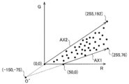
- FIG. 3 is a diagram illustrating an example of a reference axis in the color space used in one embodiment.
- the plot shown in FIG. 3 was obtained as a result of analyzing a large number of reference images inside the organ.
- the reference images used in the analysis include an example of an inflammation image with the highest degree of inflammation (an example of an inflammation image with the most severe level) and an example of an inflammation image with the lowest degree of inflammation (substantially considered to be a healthy part). Image examples) and other inflammation image examples of each stage are included.
- FIG. 3 only a part of the plot obtained as a result of the analysis is shown for convenience of clarifying the drawing.
- the number of plots actually obtained as a result of the analysis is much larger than the number of plots shown in FIG.
- the axis on the boundary line passing through 76) is set as the axis having the highest degree of inflammation, that is, the axis having a high correlation with the part having the highest degree of inflammation.
- This axis is the hemoglobin change axis AX1.
- the hemoglobin change axis AX1 is the axis on which the pixel correspondence points plotted as the degree of inflammation of the living tissue increases.
- the axis on the boundary line passing through 192) is set as the axis with the lowest degree of inflammation, that is, the part with the lowest degree of inflammation, which is highly correlated with what is considered to be a substantially healthy part. To. This axis is the mucosal change axis AX2.
- the mucosal change axis AX2 is superposed with plots corresponding to the lowest degree of inflammation imaged under various imaging conditions, for example, under various illumination conditions, that is, what is considered to be a substantially normal part. .. Therefore, the mucosal change axis AX2 is the axis on which the pixel correspondence points plotted as the degree of inflammation decreases (closer to the healthy part) converge.
- the highest degree of lesion in the lesion is accompanied by bleeding.
- the part with the lowest degree of lesion is a substantially normal healthy part, and is therefore covered with sufficient mucosa. Therefore, the plot in the RG color space shown in FIG. 3 can be regarded as being distributed in the region sandwiched between the axis having the highest correlation with blood (hemoglobin pigment) and the axis having the highest correlation with mucosal color. .. Therefore, of the boundary lines between the areas where the plot is distributed and the areas where the plot is not distributed, the boundary line closer to the R axis (stronger R component) is the axis indicating the inflamed area with the highest degree of inflammation (hemoglobin change axis AX1).
- the boundary line closer to the G axis corresponds to the axis indicating the inflamed part with the lowest degree of inflammation (mucosal change axis AX2).
- a process of calculating the redness of the living tissue which indicates the degree of redness, which will be described later, is performed on the color component of the normally projected image.
- color correction is performed on the normally projected pixel data.
- the reference axis shown in FIG. 3 is an example, and the reference axis varies depending on the type of disease.
- the pretreatment unit 220a performs color correction on the color components of the image represented in the RG color space before calculating the inflammation evaluation value.
- the correction matrix coefficient is stored in the memory 204. Pretreatment unit so that the inflammation evaluation values described later do not vary (in other words, to suppress inter-individual errors of the electronic scope) when images are taken with different electron endoscopy systems despite the same inflammation area.
- the 220a corrects the pixel data (R, G), which is the pixel corresponding point in the RG color space of each pixel, as shown in the following equation using the correction matrix coefficient.
- Rnew Corrected pixel data (R component)
- Gnew Corrected pixel data (G component)
- M 00 to M 11 Correction matrix coefficient
- R Pixel data before correction (R component)
- G Pixel data before correction (G component)
- the image evaluation value calculation unit 220b selects one pixel of interest from the pixels, and calculates the deviation angle for calculating the degree of inflammation of the selected pixel of interest based on the information of the color component of the pixel of interest. That is, a quantification process is performed to quantify the degree of redness of the living tissue based on the information of the color component of the pixel.
- FIG. 4 is a diagram illustrating a method of calculating a deviation angle for calculating the redness of living tissue used in one embodiment. Specifically, as shown in FIG.
- the image evaluation value calculation unit 220b sets the intersection of the hemoglobin change axis AX1 and the mucosa change axis AX2 as the reference point O', and sets the reference point O'and the pixel corresponding point of the pixel of interest.
- the deviation angle ⁇ at which the direction of the line segment L connecting P deviates from the reference axis AX1 is calculated.
- the reference point O' is located at the coordinates (-150, -75).
- the example in which the reference point O'is set to the coordinates (-150, -75) is given, but the present invention is not limited to this.
- the reference point O' can be changed as appropriate, and may be, for example, an intersection of the R axis and the G axis in the RG color space.
- a suitable coordinate position as the reference point O'is for example, a position where an error in the evaluation result due to fluctuations in brightness can be reduced.
- the reference point O' is determined in advance to minimize the error between the evaluation result in the dark part (brightness is less than the predetermined value) and the evaluation result in the non-dark part (brightness is more than the predetermined value). It is preferable to set it.
- the coordinates (-150, -75) and the like are compared with the case where the reference point O'is set. Therefore, the amount of change in the angle ⁇ when the pixel correspondence point changes becomes large, so that the resolution is improved. As a result, a highly accurate evaluation result can be obtained.
- the evaluation result indicating the degree of inflammation is not easily affected by noise.
- the color of the image is generally affected by individual differences, the location of the image, the state of inflammation, etc., but in the RG color space. In the most severely inflamed area, it changes along the hemoglobin change axis AX1, and in the inflamed area with the lowest degree of inflammation, it changes along the mucosal change axis AX2. In addition, it is presumed that the color of the image of the inflamed area where the degree of inflammation is intermediate changes with the same tendency.
- the pixel corresponding point corresponding to the inflamed portion changes depending on how the illumination light hits, the pixel corresponding point shifts in the azimuth direction starting from the reference point O'.
- the deviation angle ⁇ with respect to the mucosal change axis AX2 moves while being constant, and the distance from the reference point O'changes. This means that the shift angle ⁇ is a parameter that is substantially unaffected by changes in the brightness of the image.
- the image evaluation value calculation unit 220b normalizes the angle ⁇ so that the value becomes 255 when the deviation angle ⁇ is zero and the value becomes zero when the deviation angle ⁇ is ⁇ MAX .
- ⁇ MAX is equal to the angle formed by the hemoglobin change axis AX1 and the mucosal change axis AX2.
- the image evaluation value calculation unit 220b sets a value in the range of 0 to 255 obtained by normalizing the deviation angle ⁇ calculated based on the information of the color component of each attention pixel for each attention pixel, as the biological tissue redness (pixel). It is calculated as an evaluation value).
- the pixel of interest is selected one by one for all the pixels of the image.
- the RG color space is used as the color space, but the RB color space can be used instead of the RG color space.
- the image evaluation value calculation unit 220b calculates the redness of the living tissue, which is a value obtained by normalizing the deviation angle ⁇ , as the pixel evaluation value. In some cases, the whiteness of the living tissue indicating the degree of the characteristic of the ulcer of the living tissue is calculated. It can also be calculated as a pixel evaluation value.
- a gain adjustment that gives a linear gain (gain) to the pixel value of each color component of each pixel of an image of a living tissue is performed to substantially widen the dynamic range in the vicinity of the color gamut peculiar to a lesion, and color
- tone enhancement treatment that enhances the effective resolution of expression, for example, inflammation showing white ulcers including white moss and purulent mucus of ulcerative colitis and red color including edema and easy bleeding. It can be distinguished by the color component from the normal part showing a part or yellow or green.
- the whiteness of biological tissue is a color used as the coordinate axis of two color components (R component, G component, and B component) or three color components (R component, G component, and B component) as shown in FIG. It can be calculated by using the deviation angle with respect to the reference axis different from the reference axis AX represented in space.
- the tone enhancement process is performed by the preprocessing unit 220a.
- the image evaluation value calculation unit 220b calculates one image evaluation value using the pixel evaluation value of each pixel. For example, the pixels representing the image of the living tissue to be evaluated are selected from the captured images, and the integrated value or the average value of the pixel evaluation values of the selected pixels is calculated as one image evaluation value. Alternatively, for example, among the RGB color components or pixel brightness components for each pixel, the pixels to be evaluated are extracted based on the color components or brightness components in a predetermined range, and the average value of the pixel evaluation values of the extracted pixels is extracted. The image evaluation value calculation unit 220b calculates one image evaluation value by obtaining a weighted average value using a predetermined weighting coefficient, or by performing an integration process.
- the pixel portion to be evaluated in the image is a portion having a value of a color component within a predetermined range assumed in a living tissue in order to evaluate the degree of inflammation of an organ with high accuracy, and is illuminated by illumination light. It is preferable that the portion of the pixel has an illuminated brightness component of a predetermined value or more.
- the image evaluation value calculated by the image evaluation value calculation unit 220b is sent to the determination unit 220d and the lesion evaluation unit 220e.
- the image evaluation value calculation unit 220b further creates a color map image in which the image of the living tissue is mosaicked with a display color that changes according to the redness of the living tissue.
- a table in which the pixel evaluation value and the predetermined display color are associated with each other is stored in the storage area of the memory 204.
- different display colors are associated with each value in increments of 5.
- blue is associated with a pixel evaluation value in the range of 0 to 5
- different display colors are associated with each increase of the pixel evaluation value by 5 according to the order of colors in the color wheel.
- Red is associated with the pixel evaluation value in the range of 250 to 255.
- the display color is a color that approaches a warm color from a cold color, for example, from blue to yellow to red as the degree of redness of the living tissue increases.
- the image evaluation value calculation unit 220b determines the display color of the selected pixel of interest on the color map image based on the above table according to the redness of the biological tissue of the pixel of interest. In this way, the image evaluation value calculation unit 220b creates a color map image in which colors are added according to the degree of redness of the living tissue.
- the image pickup position information processing unit 220c acquires position information regarding the image pickup position sent from the position measurement system 250 provided in the electronic endoscope system 1, and associates the acquired position information with the image taken.
- the position measurement system 250 uses a sensor to acquire, for example, the position of the solid-state image sensor 108 located at the tip of the electronic scope 100 inserted into the organ, and the position of each of the subsequent flexible tubes.
- the system the system for acquiring the insertion length of the electronic scope 100 inserted from the open end of the organ, or the captured image is displayed on the monitor 300, and the operator who sees this image can see the inside of the inserted organ.
- This is a system for acquiring a specific partial passage signal indicating that the tip portion of the electronic scope 100 has passed through the characteristic portion of the above.
- the acquired information of the imaging position is sequentially sent to the determination unit 220d and the lesion evaluation unit 220e.
- a position near the solid-state image sensor 108 at the tip of the electronic scope 100 and a flexible tube following the tip to the processor 200 side A plurality of magnetic sensors are provided at predetermined intervals, and an electron scope 100 applies a magnetic field having different strength depending on the position from the outside of the human body inserted into the organ, and the magnetic sensor measures the strength of the magnetic field.
- the position of the magnetic sensor provided at the tip portion can be known, and further, the curved shape in the organ of the flexible tube can be known from the positions of the plurality of magnetic sensors.
- the position of the tip of the solid-state image sensor 108 can be known, and the shape of the electron scope 100 in the organ and the insertion length of the electron scope 100 from the open end can be known.
- the optical flow shows how much the biological tissue has moved between adjacent images in the captured moving image.
- Information on the insertion length of the current electronic scope 100 can be acquired by acquiring using the process and integrating the acquisition results to calculate the moving distance. Further, for example, information on the current insertion length of the electron scope 100 can be obtained by measuring the length of the flexible tube extending from the tip of the inserted electron scope 100 toward the inside of the organ. can do.
- the operator sees the image displayed on the monitor 300, and when the identifiable specific part inside the organ appears in the image and passes through, the button that the operator has at hand. By pressing, a specific partial passage signal is generated, and the imaging position information processing unit 220c can acquire this specific partial passage signal.
- the positions of specific parts inside the organ are, for example, when the organ is the large intestine, the position where the ascending colon begins, the position where the ascending colon ends and the large intestine bends and the transverse colon begins, and the position where the transverse colon ends and the large intestine bends and descends.
- the position where the descending colon ends, the large intestine bends and the sigmoid colon begins, the position where the sigmoid colon ends and the rectum begins, and the position where the rectum ends and reaches the anus.
- the determination unit 220d is configured to determine whether or not the degree of lesion changes in the section based on the degree of variation in the image evaluation values of the plurality of images captured in the section. By making such a determination, an index (representative evaluation value) indicating the degree of lesion in the section can be obtained more appropriately, and the degree of lesion can be evaluated accurately.
- the variation in the evaluation value may be the variation in the image evaluation value of all the images captured in the section, or may be the variation in the image evaluation value of some images as described later.
- a section in which the degree of lesion changes a section in which a plurality of lesion degrees exist and a section in which both a lesion and a normal part exist are included.
- Examples of the degree of the plurality of lesions include a plurality of ranks or a plurality of levels, which will be described later, which are different from each other.
- the determination unit 220d makes a determination using an index indicating the degree of variation obtained from the image evaluation value, and the degree of variation indicated by this index is equal to or higher than a predetermined threshold value (predetermined value). In some cases, it is preferably configured to determine that the extent of the lesion has changed within the section. Examples of such indicators include the following indicators 1 to 4. Index 1: Difference between the maximum and minimum values of the image evaluation values (the size of the range of image evaluation values) Index 2: Standard deviation (or variance) of the image evaluation value Index 3: An index showing the degree of fit of the regression line obtained by regressing the image evaluation value in the order of the images taken. Index 4: Slope of the regression line obtained by regressing the image evaluation value to the imaging position.
- FIGS. 5 to 8 show graphs showing the relationship between the number of measurements (number of images taken) in each section and the image evaluation value of the captured image for a certain two sections
- FIG. 8A shows the image evaluation value of the image evaluation value.
- a graph in a section with a small variation is shown
- (b) shows a graph in a section with a large variation in the image evaluation value.
- the number of measurements (number of imagings) on the horizontal axis indicates that the plot located on the right side is the one that was imaged later, and the number of measurements is from left to right in the order of imaging. Lined up in the direction.
- the horizontal axis indicates the imaging position along the depth direction in the organ, and the plot located on the right side indicates that the image was taken on the side of the open end of the organ.
- a threshold value for distinguishing the degree of variation in the image evaluation value between FIGS. 5 (a) and 5 (b) regarding the difference between the maximum value and the minimum value of the image evaluation value is set.
- the strength of the lesion changes within the section when the difference between the maximum value and the minimum value is equal to or greater than the threshold value as shown in FIG. 5 (b). ..
- the difference between the maximum value and the minimum value is less than the threshold value as shown in FIG. 5A, it can be determined that the lesion strength has not changed within the interval.
- a threshold value for distinguishing the degree of variation in the image evaluation value between FIGS. 6 (a) and 6 (b) should be set in advance with respect to the standard deviation (or variance). Therefore, when the standard deviation (or variance) is equal to or greater than the threshold value as shown in FIG. 6B, it can be determined that the strength of the lesion changes within the interval. Further, when the standard deviation (or variance) is less than the threshold value as shown in FIG. 6A, it can be determined that the lesion strength has not changed within the interval. Note that FIGS. 6A and 6B show the average value of the image evaluation values used in the calculation of the standard deviation (or variance).
- the degree of variation in the image evaluation value caused by the change in the brightness of the image is less than the threshold value, and the image caused by the change in the degree of lesion within the section.
- the degree of variation in the evaluation value is set to be equal to or higher than the threshold value.
- a threshold value for distinguishing the degree of variation of the image evaluation value with respect to the regression line between FIGS. 7 (a) and 7 (b) is set in advance with respect to the degree of fit of the regression line.
- y i captured image evaluation value y 'i of the image: the image evaluation value Y on the regression line: Mean value n of the image evaluation value of captured image: Number of captured images
- the coefficient of determination is indicated by a value from 0 to 1, and the closer it is to 1, the better the fit of the regression line.
- the threshold is set to a value between 0 and 1. As a result, when the coefficient of determination exceeds a predetermined threshold value, it is determined that the strength of the lesion changes within the section. If the coefficient of determination is less than or equal to the threshold value, it is determined that the lesion strength has not changed within the interval.
- the electronic endoscope system 1 does not have to have the position measurement system 250 and the imaging position information processing unit 220c.
- the graphs shown in FIGS. 5 to 7 there is no correlation between the image evaluation value and the imaging position, but whether or not the degree of lesion changes within the section using the above indicators 1 to 3. Can be determined.
- the variation of the image evaluation value may be large as shown in FIG. 8 (b). In this case, since it should be determined that the degree of lesion has changed within the section, it is preferable to make the determination using the index 4 described above.
- the determination unit 220d makes a determination using the inclination of the regression line obtained by regressing the image evaluation values in the order of the imaging positions along the depth direction, and the inclination is greater than or equal to a predetermined value. In some cases, it is preferably configured to determine that the extent of the lesion has changed within the section. In this case, it is preferable that the determination unit 220d is configured to perform a determination using the slope of such a regression line when the index indicating the degree of fit exceeds the threshold value.
- the slope of the regression line is not only when the index indicating the degree of fit of the regression line exceeds the threshold value, but also when the index indicating the degree of fit of the regression line is below the threshold value (when the fit is good). If is large, it can be determined that the degree of lesion has changed. On the other hand, when the index indicating the degree of fit of the regression line is equal to or less than the threshold value, it can be determined that the degree of lesion has not changed when the slope of the regression line is small.
- the determination using such an index 4 can be performed when the electronic endoscope system 1 includes the imaging position information processing unit 220c and the position measurement system 250.
- a threshold value for distinguishing the degree of variation in the image evaluation value between FIGS. 8 (a) and 8 (b) is set in advance with respect to the slope of the regression line.
- FIG. 8B when the slope of the regression line is equal to or greater than the threshold value, it can be determined that the strength of the lesion changes within the interval.
- FIG. 8A when the slope of the regression line is less than the threshold value, it can be determined that the strength of the lesion has not changed within the section.
- the determination is made using the index 4 it is possible to know how the strength of the lesion changes and the degree of the change. For example, it can be seen whether the strength of the lesion changes suddenly or slowly.
- the determination unit 220d further utilizes the imaging position information to determine the degree of lesion. It is preferable to identify the region within the section where is changing. By identifying the region where the strength of the lesion has changed, the region where the degree of lesion has changed exists, for example, in a spot shape or continuously so as to be connected to the lesion portion in the adjacent section. You can see if it is.
- the spot-like regions may exist in various depth directions depending on the length of the section. For example, there are cases where one or a plurality of spot-like regions exist in one section, and there are cases where they continuously exist over two or three or more sections.
- a region in which the degree of lesion has changed a region within one lesion that continuously spreads in the depth direction and a section including a boundary between the lesion and a normal portion (start position or end position described later). There is an area.
- the determination unit 220d further specifies the degree of change in the intensity of the lesion with respect to the region in the section where the degree of the lesion is changing by using the information of the imaging position. It is also preferable. For example, depending on whether the degree of change (inclination) of the lesion strength is greater than or equal to a predetermined threshold value or less than the threshold value, it can be determined whether the change in lesion strength is rapid or gradual. Further, depending on the direction of change in the strength of the lesion along one direction in the depth direction, it can be seen whether the strength of the lesion is stronger or weaker in the one direction. That is, according to one embodiment, it is preferable that the determination unit 220d is configured to specify the degree of change in the lesion in the section according to the magnitude of the inclination of the regression line.
- the lesion site calculation unit 220f may be configured to perform these identifications performed by the determination unit 220d.
- the determination unit 220d is configured to perform determination based on the variation of some image evaluation values among the image evaluation values. For example, when water for cleaning, blood, stool, etc. adheres to the part of the living tissue to be imaged or the tip of the endoscope, the image greatly deviates from the average value of the image evaluation values of all the images captured. The evaluation value may be calculated. If it is determined whether or not the degree of the lesion has changed within the section based on the variation in the image evaluation value including such outliers, the accuracy of the determination is lowered. In this embodiment, the strength of the lesion changes within the section by making a judgment based on the variation of the remaining image evaluation values excluding the outliers as some of the image evaluation values.
- the degree of lesion can be evaluated with high accuracy.
- outliers for example, from the maximum value, the minimum value, or both of the image evaluation values of all the images captured in the section, the range of variation of the image evaluation values (maximum value and minimum value).
- the image evaluation value within a predetermined ratio for example, several%) of the difference
- the inflammation evaluation value outside the range of the predetermined inflammation evaluation value may be excluded.
- outliers detected by the test are excluded from the image evaluation values of all the images captured in the section, and the test is performed again to detect another outlier. And repeat the exclusion.
- the outliers are preferably excluded from the image evaluation values obtained when all the images are imaged in the region in the organ to be imaged or in a predetermined segment. According to one embodiment, the image can be excluded while being reproduced.
- the lesion evaluation unit 220e uses the information regarding the imaging position sent from the imaging position information processing unit 220c to divide the region inside the imaged organ into a plurality of sections at predetermined intervals, and the living body of each of the plurality of sections.
- a representative evaluation value of the image evaluation value is calculated from the image evaluation values of a plurality of images obtained by imaging the tissue.
- the lesion evaluation unit 220e evaluates the spread of the lesion continuously spreading in the depth direction inside the organ by using the representative evaluation value. For example, in the case of ulcerative colitis in the large intestine, it can be evaluated that the lesion has spread from the rectum to the descending colon. In such an evaluation, the extent of the lesion can be evaluated assuming that the region where the representative evaluation value exceeds a preset threshold value is the lesion portion.
- the section may be predetermined by the operator, or the section may be divided by a specific partial passage signal.
- a section is defined by a specific partial passage signal, the section is called a segment.
- This segment is a part of one organ that can be distinguished from the other, for example, if the organ is the large intestine, the ascending colon segment, the transverse colon segment, the descending colon segment, the S-shape. Includes colon segment, rectal segment, etc.
- Such segments are separated by specific partial passage signals.
- the lesion evaluation unit 220e has a representative value determination unit 220h.
- the representative value determining unit 220h differs in the representative evaluation value depending on whether the determination unit 220d determines that the lesion intensity has changed within the section or has not changed. It is configured to be determined by the method.
- the brightness of the image changes depending on the shooting conditions such as the distance between the subject and the endoscope. Therefore, even if a site of a living tissue having the same inflammation intensity is imaged, the image evaluation value fluctuates and varies. On the other hand, the image evaluation value also fluctuates when the degree of the lesion changes along the depth direction in the organ, and the variation occurs.
- the image evaluation is performed not only when the image evaluation value varies due to the brightness of the image but also when the intensity of inflammation changes. Even if the values vary, it becomes a representative evaluation value indicating the average intensity of inflammation. As a result, it becomes difficult to understand that there is a lesion portion showing a stronger inflammation intensity than the representative evaluation value indicates in the section, and it is not possible to appropriately judge the inflammation intensity. Knowing the strength of a lesion is important in considering a treatment method for the lesion. Therefore, as described above, the representative value determining unit 220h determines the representative evaluation value by a different method depending on whether the lesion strength is determined to be changed or not. Determine. As a result, an index that appropriately indicates the degree of lesion in the section can be obtained, and the degree of lesion can be evaluated accurately.
- the method is preferably a statistical method.
- the representative value determining unit 220h determines at least a part of the images captured in the section when it is determined that the intensity of the lesion changes in the section. It is preferable that the maximum value among the evaluation values of the image of is set as the representative value of the section. This makes it possible to optimally indicate the degree of lesion in the section where the degree of lesion is changing. Further, according to one embodiment, when it is determined that the degree of lesion does not change in the section, the representative value determining unit 220h determines at least a part of the images captured in the section.
- any one of the average value, the mode value, and the median value of the evaluation values is set as the representative value of the section. Since it is considered that the variation in the evaluation value in the section where the degree of lesion has not changed is due to the imaging conditions, the strength of the lesion in the section can be appropriately determined by using these statistics as representative values. Can be shown.
- the maximum value, or any one of the average value, the mode value, and the median value is preferably determined based on the evaluation values of all the images captured in the interval, but as described above. In the case of excluding outliers from the image evaluation values as described above, it is preferable that the values are obtained based on the remaining image evaluation values.
- the lesion evaluation unit 220e may include the section identification unit 220i according to one embodiment. preferable.
- the section specifying unit 220i is configured to use the information of the imaging position to specify the section in which section the image associated with the acquired information is the image captured in the plurality of sections. ..
- the lesion evaluation unit 220e is configured to evaluate the degree of lesion by dividing it into a plurality of ranks related to the strength of the lesion, and the lesion evaluation unit 220e is based on a representative evaluation value. It is preferable to determine one of a plurality of ranks and evaluate the degree of lesion for each section. This makes it possible for the operator to accurately inform the operator of the extent and strength of the lesion that continuously spreads in the depth direction inside the organ. Further, according to one embodiment, it is preferable that the lesion evaluation unit 220e determines the presence or absence of a lesion portion in which the lesion is continuously spread in the depth direction of the organ for each section based on the representative evaluation value.
- the region of the lesion is a region in which the representative evaluation value is larger than the preset threshold value.
- the lesion evaluation unit 220e can also determine the presence or absence of a lesion portion in which the lesion is continuously spread in the depth direction of the organ based on the image evaluation value.
- the region of the lesion is a region where the image evaluation value is larger than the preset threshold value. Since the image evaluation value is an evaluation value for each image, it may include a noise component. In this case, it is preferable to use the representative evaluation value for each section instead of the image evaluation value.
- the lesion site calculation unit 220f obtains the start position and the end position of the lesion area by obtaining the section in which the lesion is located among the above sections based on the position information of the captured image. Identify the location of the lesion. In order to accurately determine the start position and end position of the lesion, it is also preferable to determine the position where the image evaluation value crosses a predetermined threshold value by using the image evaluation value and the position information obtained by capturing the image. .. In this case, the lesion evaluation unit 220e compares each image evaluation value with the threshold value to determine whether or not the image evaluation value crosses the threshold value. This determination result is sent to the lesion site calculation unit 220f.
- the lesion evaluation unit 220e preferably calculates the length of the lesion portion from the information on the start position and the end position of the lesion portion obtained by the lesion site calculation unit 220f. Therefore, according to one embodiment, it is preferable that the monitor 300 displays at least one of the start position, the end position, and the length of the lesion on the screen. This makes it easier for the operator to recognize the extent of the lesion organ in the depth direction. Further, the lesion evaluation unit 220e obtains the total value of the representative evaluation values corresponding to the sections included between the start position and the end position of the lesion part among the plurality of sections, and evaluates the degree of the lesion by the total value. It is preferable to do.
- the total value can be divided into a plurality of levels and the degree of lesion can be evaluated according to the level.
- the lesion evaluation unit 220e When many sections are set by shortening the length of the predetermined section, the lesion evaluation unit 220e provides position information along the depth direction of each section (for example, the distance from the deepest part of the electronic scope to the opening end).
- the curve created by the representative evaluation value for each section may be uneven in the adjacent section.
- the representative evaluation shown in the above graph is performed by performing a moving average process or a curve fitting process using a function indicating a predetermined curve by using the position information of the section and the representative evaluation value. It is preferable to process the value curve smoothly.
- FIG. 9 is a diagram showing an example of a flow performed by the evaluation unit 221 from image acquisition to obtaining a representative evaluation value for each section.
- the maximum value among the image evaluation values corresponding to the section is used as the representative evaluation value.
- the average value of the image evaluation values corresponding to the section is used as the representative evaluation value, but the median value or the mode value may be used. Good.
- the preprocessing unit 220a acquires an image (step S10) and performs the above-described processing.
- the image pickup position information processing unit 220c from the position measurement system 250 acquires the image pickup position information of the acquired image in association with the captured image.
- the lesion evaluation unit 220e uses the information of the imaging position to specify the section in which the acquired image is captured inside the organ among the predetermined sections (step S12).
- the image evaluation value calculation unit 220b calculates the image evaluation value using the image processed by the preprocessing unit 220a (step S14). Note that step S14 is not limited to being performed after step S12, and can be performed before or at the same time as step S12.
- the lesion evaluation unit 220e determines whether or not the degree of lesion has changed in the section based on the image evaluation value calculated for the image captured in the section. Specifically, the lesion evaluation unit 220e compares the difference between the maximum value and the minimum value (“MAX-min”) of the calculated image evaluation values in the section with the predetermined threshold value ⁇ (step S16). If the difference is less than the threshold value (YES in step S16), it is determined that the degree of lesion has not changed within the section, and the average value of the image evaluation values within the section is calculated (step S18). This is used as a representative evaluation value (step S22).
- the lesion evaluation unit 220e determines that the degree of the lesion has changed within the section, and further, among the image evaluation values in the section. The maximum value is calculated (step S20), and this is used as the representative evaluation value (step S22).
- step S16 instead of comparing the difference between the maximum value and the minimum value of the image evaluation value and the threshold value, the standard deviation or variance of the image evaluation value is compared with the threshold value. You may.
- steps S10 to S24 are repeated until the preprocessing unit 220a finishes acquiring the image (step S24).
- the evaluation unit 221 obtains a representative evaluation value for each section.
- FIG. 10 is a diagram showing an example of a flow performed by the evaluation unit 221 from image acquisition to obtaining a representative evaluation value for each section.
- steps S30, S32, S34, S40, S42, S44, and S46 perform the same steps as steps S10, S12, S14, S18, S20, S22, and S24 of the flow shown in FIG. ..
- the determinations in steps S36 and S38 are performed in order to determine whether or not the degree of change in the lesion has changed within the section.
- the lesion evaluation unit 220e obtains a regression line obtained by regressing the image evaluation value in the section calculated in step S34 to the imaging position acquired from the imaging position information processing unit 220c, and calculates the coefficient of determination.
- the calculated coefficient of determination is compared with the predetermined coefficient ⁇ (step S36), and when the coefficient of determination exceeds the threshold (YES in step S36), the slope of the regression line (regression coefficient) and the predetermined threshold ⁇
- the slope of the regression line is less than the threshold value (YES in step S38)
- the average value of the image evaluation values in the section is calculated (step S40), and this is used as the representative evaluation value. (Step S44).
- step S36 when the coefficient of determination is equal to or less than the threshold value in step S36 (NO in step S36) and when the slope of the regression line is equal to or greater than the threshold value in step S38 (NO in step S38), the maximum image evaluation value in the section is maximum. A value is calculated (step S42), and this is used as a representative evaluation value (step S44).
- the above-mentioned outliers may be excluded before the determinations in steps S16 and S36 are performed.
- the evaluation result integrated unit 220 g includes evaluation results, a graph showing the numerical value of the representative evaluation value for each section, the distribution of the representative evaluation value in each section for the section, information showing the extent of the lesion in the depth direction, and the lesion. Information on the start position, end position or lesion length of the part, and information on the ranked strength of the lesion for each section are integrated and monitored as one or more evaluation result screens 300. To display.
- FIG. 11 is a diagram illustrating a large intestine, which is an example of an organ.
- the large intestine comprises the rectum, the sigmoid colon, the descending colon, the transverse colon, and the ascending colon, in order from the open end (anus).
- the rectum is referred to as segment SG5
- the sigmoid colon is referred to as segment SG4
- the descending colon is referred to as segment SG3
- the transverse colon is referred to as segment SG2
- the ascending colon rectum is referred to as segment SG1.
- the electron scope 100 is inserted to the deepest part of the segment SG1 which is the ascending colon, and moves from there so as to be pulled out toward the opening end side at a substantially constant moving speed. Therefore, the electronic scope 100 captures images in the order of segment SG1, segment SG2, segment SG3, and so on.
- FIG. 12 is a diagram showing an example of the evaluation result by the lesion evaluation unit 220e.
- the evaluation result shown in FIG. 12 is a graph in which the horizontal axis represents the positions from the segment SG5 to the segment SG1 and the vertical axis represents the integrated evaluation value. It is preferable that the number of images captured in each segment is equal.
- a plurality of sections are designated as segments SG1 to SG5, and a segment having a representative evaluation value equal to or higher than the threshold value is shown as an inflamed lesion portion with a predetermined threshold value as a boundary.
- FIG. 12 it is shown that a part of segment SG5, segment SG4, and segment SG3 is inflamed. According to one embodiment, such an evaluation result is displayed on the monitor 300.
- FIG. 13 is a diagram showing another example of the evaluation result by the lesion evaluation unit 220e. Similar to FIG. 12, the evaluation result shown in FIG. 13 is a graph in which the horizontal axis represents the positions from the segment SG5 to the segment SG1 and the vertical axis represents the representative evaluation value. In the example shown in FIG. 13, the degree of lesion is evaluated in four ranks regarding the strength of the lesion, that is, “strong inflammation”, “medium inflammation”, “low inflammation”, and “no inflammation”. It is configured to be evaluated separately.
- the lesion evaluation unit 220e determines one of a plurality of ranks based on the representative evaluation value, and evaluates the degree of lesion for each segment. Therefore, in the example shown in FIG.
- inflammation exists from a part of segment SG3 to segment SG5, and the degree of inflammation (lesion intensity) of segment SG5 and segment SG4 is evaluated to be strong, and the segment The degree of inflammation of SG3 is evaluated as moderate. According to one embodiment, such an evaluation result is displayed on the monitor 300.
- FIG. 14 is a diagram showing another example of the evaluation result by the lesion evaluation unit 220e.
- the evaluation result shown in FIG. 14 is a graph showing the representative evaluation value for each section, in which the horizontal axis represents the position in the large intestine in the depth direction and the vertical axis represents the representative evaluation value.
- the section shows a narrow range as compared with the segments SG1 to SG5, and more specifically, a section in which each segment is divided into two is set.
- a section having a representative evaluation value equal to or higher than the threshold value can be defined as an inflamed lesion portion with a predetermined threshold value as a boundary. According to one embodiment, such an evaluation result is displayed on the monitor 300.
- the electronic endoscope system 1 preferably includes a monitor 300.
- the evaluation result integration unit 220g further integrates the presence / absence of a section in which the degree of lesion has changed, the region in which the degree of lesion has changed, and the degree of change in the evaluation result screen. It is preferable to display it on the monitor 300.
- character information indicating that is added, or the plot and / or the area between the plots indicating the representative evaluation value in the graph is added. It is shown in an emphasized display mode such as a display color different from other parts.
- the monitor 300 uses the information of the determination result as to whether or not the degree of the lesion has changed, when it is determined that the degree of the lesion has changed and when it is determined that the degree has not changed. It is preferable that the screen is displayed in a different display mode.
- FIG. 15 is a diagram showing an example of a screen including one frame of a moving image displayed on the monitor 300.
- the captured image IM is shown on the left side of the screen.
- a schematic diagram of the large intestine FIG. FIG. FIG. The color map image CM in which is replaced is shown, and below that, the score SC, which is an image evaluation value indicating the degree of inflammation, is shown.
- the score SC is 40. Further, in the screen example of FIG.
- the above-mentioned information such as the section where the degree of the lesion has changed is, for example, a display color in which the corresponding segment or the region between the segments in the large intestine schematic diagram FIG is different from other parts. It is shown in a highlighted display mode.
- the various display screens displayed on the monitor 300 are integrated by the evaluation result integration unit 220 g according to the input instruction of the operator, and a screen like the example shown in FIG. 15 is created.
- the electronic endoscopy system 1 described above may evaluate the degree of lesion online when the electron scope 100 is currently inserted into an organ for measurement, or an image is recorded in a memory 204 in advance. At a later date, the extent of the lesion in the depth direction of the organ may be evaluated while reproducing the image captured by the electron scope 100 and calculating the image evaluation value, the representative evaluation value, and the like. When the evaluation is performed while reproducing the image captured by the electronic scope 100 at a later date, the evaluation is not limited to the reproduction by the electronic endoscope system 1. For example, the image recorded in the memory 204 can be read out to another data processing device, and the extent of the lesion in the depth direction of the organ can be evaluated while reproducing the image and calculating the image evaluation value, the representative evaluation value, and the like. ..
- the data processing device of the embodiment described below is a data processing device that processes an image of a living tissue in an organ spreading in the depth direction.
- An evaluation value calculation unit configured to obtain an evaluation value indicating the degree of lesion in a living tissue of each of a plurality of images taken in a predetermined section along the depth direction of a region in an organ.
- a determination unit configured to determine whether or not the degree of lesion has changed within the section based on the degree of variation in the evaluation value.
- a representative value determination unit configured to determine the representative value of the section representing the evaluation value by different methods depending on whether the degree of lesion is changed or not. , Equipped with.
- the data processing device further includes a monitor configured to display information on a determination result of whether or not the degree of lesion has changed.
- the degree of lesion changes in the section based on the degree of variation in the image evaluation values of the plurality of images captured in the section.
Landscapes
- Health & Medical Sciences (AREA)
- Life Sciences & Earth Sciences (AREA)
- Engineering & Computer Science (AREA)
- Surgery (AREA)
- Physics & Mathematics (AREA)
- Biomedical Technology (AREA)
- Animal Behavior & Ethology (AREA)
- Radiology & Medical Imaging (AREA)
- Optics & Photonics (AREA)
- Nuclear Medicine, Radiotherapy & Molecular Imaging (AREA)
- Biophysics (AREA)
- Heart & Thoracic Surgery (AREA)
- Medical Informatics (AREA)
- Molecular Biology (AREA)
- Pathology (AREA)
- General Health & Medical Sciences (AREA)
- Public Health (AREA)
- Veterinary Medicine (AREA)
- Signal Processing (AREA)
- General Physics & Mathematics (AREA)
- Theoretical Computer Science (AREA)
- Computer Vision & Pattern Recognition (AREA)
- Endoscopes (AREA)
Abstract
電子内視鏡システムは、評価値算出部と、判定部と、代表値決定部と、を備える。評価値算出部は、器官内の領域の奥行き方向に沿った所定の区間内で撮像された複数の画像それぞれの生体組織の病変の程度を示す評価値を求めるよう構成されている。判定部は、前記評価値のばらつきの程度に基づいて、前記区間内で病変の程度が変化しているか否かを判定するよう構成されている。代表値決定部は、前記評価値を代表する前記区間の代表値を、病変の程度が変化していると判定された場合と、変化していないと判定された場合とで異なる方法で定めるよう構成されている。
Description
本発明は、器官内の生体組織の画像を処理する電子内視鏡システム及びデータ処理装置に関する。
生体組織における病変部は、生体組織の粘膜層が薄くなって荒れて赤色を示す炎症から、粘膜層及びその下層まで部分的に欠落する潰瘍まで、種々のレベルの重症度が存在する。例えば、潰瘍性大腸炎(UC:Ulcerative Colitis)の病変の潰瘍部では、白苔や膿様粘液を含み白色になり、また、炎症部では、浮腫や易出血性を含む赤色を帯びる。このような病変部を、内視鏡システムで撮像して観察することができる。
しかし、術者が内視鏡の画像内に含まれる色の相違によって正常部と病変部とを識別できるようになるためには、熟練者の指導下で長期間のトレーニングを受ける必要がある。また、熟練した術者であっても僅かな色の違いから病変部を識別することは容易ではなく、慎重な作業が要求される。したがって、内視鏡システムは、病変部における病変の程度を客観的に数値化した評価結果を提供することが好ましい。
これに対して、画像の明るさによる炎症部の評価値の変動を抑えて安定した評価値の計算を行い、かつ、評価値の計算の処理負荷を抑えることが可能な内視鏡システムが知られている(特許文献1)。
これに対して、画像の明るさによる炎症部の評価値の変動を抑えて安定した評価値の計算を行い、かつ、評価値の計算の処理負荷を抑えることが可能な内視鏡システムが知られている(特許文献1)。
上述の内視鏡システムでは、被写体に向けて照明光を照射する光源装置と、被写体からの反射光を撮像素子により撮像し、少なくとも3つ以上の色成分を含むカラー画像を取得する画像取得部と、少なくとも3つ以上の色成分のうちの少なくとも2つの色成分によって定義される色平面内において、色平面内に設定された所定の基準点及び画像取得部で取得されるカラー画像を構成する各画素の色平面内における画素対応点を結ぶ線分と、対象疾患に相関を有する基準軸と、がなす角度に基づいて各画素の対象疾患に関する評価結果を求める評価部と、を備える。基準軸は、所定の基準点を通るように設定される。基準軸は、色平面内において炎症度が所定値以下の対象疾患と相関を有する軸及び炎症度が所定値以上である対象疾患と相関を有する軸の少なくとも一方である。
このような構成によれば、画像の明るさによる炎症評価値の変動を抑えて、安定した炎症評価値の計算を行い、かつ、炎症評価値の計算の処理負荷を抑えることができる。
このような構成によれば、画像の明るさによる炎症評価値の変動を抑えて、安定した炎症評価値の計算を行い、かつ、炎症評価値の計算の処理負荷を抑えることができる。
しかし、画像の明るさは、例えば、被写体と内視鏡との距離等、撮影条件によって変化し、炎症の強さが同じ生体組織の部位を撮像しても、炎症評価値にばらつきが生じる。一方で、炎症評価値は、器官内の奥行き方向に沿って病変の程度が変化している場合にも、変動し、ばらつきが生じる。上記内視鏡システムにおいて、炎症評価値のばらつきが、画像の明るさに起因したものであるか、病変の程度が変化していることに起因したものであるかを理解することは難しく、病変の程度が奥行き方向に変化しているか否かを判断することは困難である。病変の程度が変化しているか否かによって、病変部を治療する方法も異なる場合がある。
そこで、本発明は、器官内部の生体組織の画像を処理する電子内視鏡システム及びデータ処理装置において、器官内の所定の領域内における病変の程度を適切に示す指標を得ることを目的とする。
本発明の一態様は、奥行き方向に広がる器官内の生体組織を撮像するよう構成された内視鏡と、撮像された生体組織の画像を処理するよう構成されたプロセッサと、を備える電子内視鏡システムである。当該電子内視鏡システムは、
前記器官内の領域の奥行き方向に沿った所定の区間内で撮像された複数の画像それぞれの生体組織の病変の程度を示す評価値を求めるよう構成された評価値算出部と、
前記評価値のばらつきの程度に基づいて、前記区間内で病変の程度が変化しているか否かを判定するよう構成された判定部と、
前記評価値を代表する前記区間の代表値を、病変の程度が変化していると判定された場合と、変化していないと判定された場合とで異なる方法で定めるよう構成された代表値決定部と、を備えることを特徴とする。
前記器官内の領域の奥行き方向に沿った所定の区間内で撮像された複数の画像それぞれの生体組織の病変の程度を示す評価値を求めるよう構成された評価値算出部と、
前記評価値のばらつきの程度に基づいて、前記区間内で病変の程度が変化しているか否かを判定するよう構成された判定部と、
前記評価値を代表する前記区間の代表値を、病変の程度が変化していると判定された場合と、変化していないと判定された場合とで異なる方法で定めるよう構成された代表値決定部と、を備えることを特徴とする。
前記判定部は、前記評価値から得られる前記ばらつきの程度を示す指標を用いて前記判定を行い、前記指標が示す前記ばらつきの程度が所定値以上である場合に、前記区間内で前記病変の程度が変化していると判定するよう構成されていることが好ましい。
前記指標は、前記評価値のうちの最大値と最小値の差であることが好ましい。
前記指標は、前記評価値の標準偏差又は分散であることが好ましい。
前記指標は、前記評価値を、前記撮像を行った前記画像の順序に回帰させた回帰直線の当てはまりの程度を示す指標であることが好ましい。
前記電子内視鏡システムは、前記画像それぞれを撮像した前記器官内における撮像位置の情報を前記画像それぞれと対応付けるよう構成された位置情報処理部をさらに備え、
前記判定部は、さらに、前記撮像位置の情報を利用して、前記病変の程度が変化している前記区間内の領域を特定することが好ましい。
前記判定部は、さらに、前記撮像位置の情報を利用して、前記病変の程度が変化している前記区間内の領域を特定することが好ましい。
前記評価値算出部が求める評価値は、前記区間を含む、前記器官内の領域を奥行き方向に区分けした複数の区間それぞれにおいて撮像された複数の画像それぞれの生体組織の病変の程度を示す評価値であり、
前記電子内視鏡システムは、前記撮像位置の情報を利用して、前記画像が前記複数の区間のうちのどの区間で撮像されたかを特定するよう構成された区間特定部をさらに備えることが好ましい。
前記電子内視鏡システムは、前記撮像位置の情報を利用して、前記画像が前記複数の区間のうちのどの区間で撮像されたかを特定するよう構成された区間特定部をさらに備えることが好ましい。
前記判定部は、前記区間のそれぞれについて前記判定を行うよう構成され、
前記代表値決定部は、前記区間のそれぞれについて前記代表値を定めるよう構成されていることが好ましい。
前記代表値決定部は、前記区間のそれぞれについて前記代表値を定めるよう構成されていることが好ましい。
前記画像それぞれを撮像した前記器官内における撮像位置の情報を前記画像それぞれと対応付けるよう構成された位置情報処理部をさらに備え、
前記判定部は、前記評価値を前記撮像位置に回帰させた回帰直線の傾きを用いて前記判定を行い、前記傾きが所定値以上の大きさである場合に、前記区間内で前記病変の程度が変化していると判定するよう構成されていることが好ましい。
前記判定部は、前記評価値を前記撮像位置に回帰させた回帰直線の傾きを用いて前記判定を行い、前記傾きが所定値以上の大きさである場合に、前記区間内で前記病変の程度が変化していると判定するよう構成されていることが好ましい。
前記判定部は、前記回帰直線の当てはまりの程度を示す指標をさらに用いて前記判定を行い、前記指標が示す前記当てはまりの程度が所定値を超える場合に、前記回帰直線の前記傾きを用いた前記判定を行うよう構成されていることが好ましい。
前記判定部は、前記回帰直線の前記傾きの大きさに応じて、前記区間内での前記病変の変化の程度を特定するよう構成されていることが好ましい。
前記判定部は、前記評価値のうちの一部の評価値のばらつきに基づいて、前記判定を行うよう構成されていることが好ましい。
前記代表値決定部は、前記区間内で前記病変の程度が変化していると判定された場合に、前記評価値のうち、当該区間で撮像された前記画像の少なくとも一部の評価値の最大値を当該区間の前記代表値とするよう構成されていることが好ましい。
前記代表値決定部は、前記区間内で前記病変の程度が変化していないと判定された場合に、前記評価値のうち、当該区間で撮像された前記画像の少なくとも一部の評価値の平均値、最頻値、及び中央値のいずれか1つを当該区間の前記代表値とするよう構成されていることが好ましい。
前記電子内視鏡システムは、前記病変の程度が変化しているか否かの判定結果の情報を、病変の程度が変化していると判定された場合と、変化していないと判定された場合とで異なる表示態様で画面表示するよう構成されたモニタをさらに備えることが好ましい。
本発明の別の一態様は、奥行き方向に広がる器官内の生体組織の画像を処理するデータ処理装置である。当該データ処理装置は、
前記器官内の領域の奥行き方向に沿った所定の区間内で撮像された複数の画像それぞれの生体組織の病変の程度を示す評価値を求めるよう構成された評価値算出部と、
前記評価値のばらつきの程度に基づいて、前記区間内で病変の程度が変化しているか否かを判定するよう構成された判定部と、
前記評価値を代表する前記区間の代表値を、病変の程度が変化していると判定された場合と、変化していないと判定された場合とで異なる方法で定めるよう構成された代表値決定部と、を備えることを特徴とする。
前記器官内の領域の奥行き方向に沿った所定の区間内で撮像された複数の画像それぞれの生体組織の病変の程度を示す評価値を求めるよう構成された評価値算出部と、
前記評価値のばらつきの程度に基づいて、前記区間内で病変の程度が変化しているか否かを判定するよう構成された判定部と、
前記評価値を代表する前記区間の代表値を、病変の程度が変化していると判定された場合と、変化していないと判定された場合とで異なる方法で定めるよう構成された代表値決定部と、を備えることを特徴とする。
上述の電子内視鏡システム及びデータ処理装置によれば、器官内の所定の領域内における病変の程度を適切に示す指標を得ることができる。
以下、本発明の実施形態の電子内視鏡システム及びデータ処理装置について図面を参照しながら説明する前に、まず、器官内部の病変の程度の評価を概念的に説明する。
(器官内部の病変の程度の評価の概要)
以下説明する実施形態の電子内視鏡システムのプロセッサは、電子内視鏡で撮像した器官内部の生体組織の画像を処理して病変の程度を評価する。病変の程度とは、少なくとも病変の強さを含み、一実施形態によれば、さらに病変の広がりを含む。器官内部の生体組織を撮像する場合、例えば、管状の器官の開口端から器官内部の奥行き方向の撮像対象とする最深部の位置まで電子内視鏡を挿入し、そこから、器官の開口端に向かって略連続的に移動しながら、器官内部の生体組織を撮像する。奥行き方向は、開口端から最深部の側に進む方向、及び最深部の側から開口端の側に進む方向の双方を含む。
生体組織の撮像される画像は、一定の時間間隔で連続して撮像した動画でもよく、また、器官内で電子内視鏡を移動しながら断続的に撮像した複数の静止画であってもよい。電子内視鏡を移動させる場合、電子内視鏡の速度を必ずしも一定にする必要はなく、また、電子内視鏡が通過した場所に戻って撮像する、すなわち移動方向を部分的に逆方向にすることもできる。なお、一実施形態では、動画の場合、電子内視鏡を略同じ速度で略同じ方向に移動しながら撮像する。
病変の程度の評価では、プロセッサは、白色光の照明光で照明した生体組織の複数の画像それぞれに対して、画像それぞれにおける病変の強さを示す画像評価値(評価値)を算出する。この画像評価値は、特に限定されないが、例えば、病変が炎症である場合、病変部(炎症部)の炎症の程度を、病変部の色成分の情報(例えば、赤色)に基づいて評価する炎症評価値を挙げることができる。
評価対象の器官は、特に限定されないが、例えば、咽頭~食道、胃、十二指腸、小腸、大腸等の消化管等を挙げることができる。
また、例えば、波長405nmのレーザ光、波長445nmのレーザ光、及び波長445nmのレーザ光で蛍光体を発光させた445~700nmの蛍光、を含んだ特殊光を用いて生体組織を照明して撮像し、撮像によって得られるRGBの3つの画像信号から2つの画像信号の比を作成し、この2つの画像信号を所定の強調処理を行った処理結果を利用して作られる画像毎の評価値、例えば萎縮性胃炎における粘膜等を評価する評価値を、上記画像評価値とすることもできる。
また、例えば、波長600nmの光、波長630nmの光、波長540nmの光をそれぞれ照明光として生体組織を照明して撮像し、撮像によって得られる画像に対して所定の強調処理を行った処理結果を利用して作られる画像毎の評価値、例えば粘膜深部の血管の状態を評価するための評価値を上記画像評価値とすることもできる。
また、光で照明された、染色等により前処理が施された消化管の粘膜の細胞を、拡大撮像して、細胞核の特徴量(長さ、直径、周長、真円度等の形状の情報)の平均値等を、非腫瘍、腺腫、癌等の病変の程度を評価するための評価値を画像評価値とすることもできる。
また、画像評価値は、画像毎に得られるMayoスコア等の評価値であってもよい。この場合、撮像した画像によって機械学習をした評価装置を用いて算出した評価値を上記画像評価値としてもよい。また、画像評価値は、病理組織学的な評価を画像毎に数値化したものであってもよい。
プロセッサは、撮像した器官内の領域の奥行き方向に沿った所定の区間で生体組織を撮像した複数の画像の画像評価値から画像評価値の代表評価値(代表値)を算出し、この代表評価値を用いて、所定の区間内の病変の程度を評価する。評価対象となる区間は、器官内の1つの区間であってもよいが、一実施形態によれば、器官内の領域を奥行き方向に区分けした複数の区間であることが好ましい。この場合、画像それぞれを撮像した際、撮像した器官内部における撮像位置の情報が画像それぞれと対応付けられる。また、一実施形態によれば、代表評価値を用いて、病変の程度を評価するように構成された病変評価部を備えることが好ましい。具体的に、プロセッサは、取得した撮像位置の情報を利用して、撮像した器官内の領域を奥行き方向に区分けした複数の区間ごとに、複数の区間それぞれについて算出した代表評価値を用いて、器官の奥行き方向に連続して広がっている病変の広がりと強さを評価する。以降の説明では、撮像位置の情報を利用して、複数の区間それぞれについて代表評価値を算出し、病変の程度として病変の強さと広がりを評価する場合を例に説明する。
ここで、区間とは、撮像位置のサンプリング間隔以上の距離で区切られた区間である。一実施形態によれば、この区間は、予め定められた間隔で区切られた区間である。予め定めた間隔は、一定の間隔であってもよいし、一定でなくてもよい。また、予め定めた間隔は、代表評価値の算出の途中で随時変更してもよい。例えば、予め細かい間隔で区切った区間を、より大きな区間に、例えば器官内で他の部分と識別可能に区別することができる部分であるセグメントに変更してもよい。
ここで、区間とは、撮像位置のサンプリング間隔以上の距離で区切られた区間である。一実施形態によれば、この区間は、予め定められた間隔で区切られた区間である。予め定めた間隔は、一定の間隔であってもよいし、一定でなくてもよい。また、予め定めた間隔は、代表評価値の算出の途中で随時変更してもよい。例えば、予め細かい間隔で区切った区間を、より大きな区間に、例えば器官内で他の部分と識別可能に区別することができる部分であるセグメントに変更してもよい。
病変の程度の評価は、一実施形態によれば、複数の区間毎に、この区間に対応した画像評価値の代表評価値を求め、代表評価値の奥行き方向の分布を表示すること、あるいは、画像評価値を用いて判定される病変部を含む区間、に対応した代表評価値の合計値を提供すること、を含む。これにより、病変の広がりと強さを同時に評価した病変の程度を、レベルに分けて評価することができる。
このように、画像それぞれを撮像した器官内部における撮像位置の情報を利用して、撮像した器官内部の領域を区分けした複数の区間毎に、画像評価値から画像評価値の代表評価値を算出して、病変の広がりを精度よく評価することができる。代表評価値は、区間における病変の強さの指標である。したがって、撮像した複数の画像毎の局所的な生体組織の病変の強さの評価だけではなく、器官の奥行き方向における病変の広がりと病変の強さを含む総合的な評価を精度よく行うことができる。ここで、病変の広がりは、病変が連続して奥行き方向に広がっていることを示す。このため、器官内で離散的に数箇所の位置で画像を離散的に撮像して画像評価値を算出しても、病変の広がりを評価することは難しい。
(電子内視鏡システムの説明)
図1は、本発明の一実施形態の電子内視鏡システム1の構成を示すブロック図である。図1に示されるように、電子内視鏡システム1は、電子スコープ100、電子内視鏡用プロセッサ200、モニタ300及びプリンタ400を備えている。
図1は、本発明の一実施形態の電子内視鏡システム1の構成を示すブロック図である。図1に示されるように、電子内視鏡システム1は、電子スコープ100、電子内視鏡用プロセッサ200、モニタ300及びプリンタ400を備えている。
電子内視鏡用プロセッサ200は、システムコントローラ202やタイミングコントローラ206を備えている。システムコントローラ202は、メモリ204に記憶された各種プログラムを実行し、電子内視鏡システム1の全体を統括的に制御する。また、システムコントローラ202は、操作パネル208に入力されるユーザ(術者又は補助者)による指示に応じて電子内視鏡システム1の各種設定を変更する。操作パネル208では、例えば、代表値として用いる統計量の設定のための入力を行うことができ、その際、後述する判定結果に応じて異なる統計量を設定することができる。タイミングコントローラ206は、各部の動作のタイミングを調整するクロックパルスを電子内視鏡システム1内の各回路に出力する。
電子内視鏡用プロセッサ200は、電子スコープ100に照明光を供給する光源部230を備えている。光源部230は、図示されないが、例えば、ランプ電源から駆動電力の供給を受けることにより白色の照明光を放射する高輝度ランプ、例えば、キセノンランプ、メタルハライドランプ、水銀ランプ又はハロゲンランプを備える。高輝度ランプから出射した照明光は、図示されない集光レンズにより集光された後、図示されない調光装置を介して電子スコープ100のLCB(Light Carrying Bundle)102の入射端に入射されるように光源部230は構成される。
あるいは、光源部230は、所定の色の波長帯域の光を出射する複数の発光ダイオードを備える。発光ダイオードから出射した光はダイクロイックミラー等の光学素子を用いて合成され、合成した光は照明光として、図示されない集光レンズにより集光された後、電子スコープ100のLCB(Light Carrying Bundle)102の入射端に入射されるように光源部230は構成される。発光ダイオードに代えてレーザーダイオードを用いることもできる。発光ダイオード及びレーザーダイオードは、他の光源と比較して、低消費電力、発熱量が小さい等の特徴があるため、消費電力や発熱量を抑えつつ明るい画像を取得できるというメリットがある。明るい画像が取得できることにより、後述する炎症に関する評価値の精度を向上させることができる。
なお、図1に示す例では、光源部230は、電子内視鏡用プロセッサ200に内蔵して設けられるが、電子内視鏡用プロセッサ200とは別体の装置として電子内視鏡システム1に設けられてもよい。また、光源部230は、後述する電子スコープ100の先端部に設けられてもよい。この場合、照明光を導光するLCB102は不要である。
入射端よりLCB102内に入射した照明光は、LCB102内を伝播して電子スコープ100の先端部内に配置されたLCB102の端より射出され、配光レンズ104を介して被写体である器官内部の生体組織に照射される。生体組織からの反射光は、対物レンズ106を介して固体撮像素子108の受光面上で光学像を結ぶ。
固体撮像素子108は、例えば、IR(Infrared)カットフィルタ108a、ベイヤ配列カラーフィルタ108bの各種フィルタが受光面に配置された単板式カラーCCD(Charge-Coupled Device)イメージセンサであり、受光面上で結像した光学像に応じたR(Red)、G(Green)、B(Blue)の各原色信号を生成する。単板式カラーCCDイメージセンサの代わりに、単板式カラーCMOS(Complementary Metal Oxide Semiconductor)イメージセンサを用いることもできる。CMOSイメージセンサは、一般に、CCDイメージセンサと比較して画像が全体的に暗くなる傾向にある。従って、以下説明する病変の程度の評価を行う数値化処理における、画像の明るさによる病変部の病変の重症度の変動を抑えることができるという有利な効果は、CMOSイメージセンサを用いる場合においてより顕著である。このように、電子スコープ100は、固体撮像素子108を用いて、器官内部の生体組織を撮像し、動画を生成する。
電子スコープ100の、プロセッサ200との接続部の内部には、ドライバ信号処理回路112が備えられている。ドライバ信号処理回路112は、固体撮像素子108より入力される原色信号に対して色補間、マトリックス演算等の所定の信号処理を施して画像信号(輝度信号Y、色差信号Cb、Cr)を生成し、生成された画像信号を電子内視鏡用プロセッサ200の画像処理ユニット220に出力する。また、ドライバ信号処理回路112は、メモリ114にアクセスして電子スコープ100の固有情報を読み出す。メモリ114に記録される電子スコープ100の固有情報には、例えば固体撮像素子108の画素数や感度、動作可能なフレームレート、型番等が含まれる。ドライバ信号処理回路112は、メモリ114より読み出された固有情報をシステムコントローラ202に出力する。
システムコントローラ202は、電子スコープ100の固有情報に基づいて各種演算を行い、制御信号を生成する。システムコントローラ202は、生成された制御信号を用いて、電子内視鏡用プロセッサ200に接続中の電子スコープ100に適した処理がなされるように電子内視鏡用プロセッサ200内の各回路の動作やタイミングを制御する。
タイミングコントローラ206は、システムコントローラ202によるタイミング制御に従って、ドライバ信号処理回路112、画像処理ユニット220、及び光源部230にクロックパルスを供給する。ドライバ信号処理回路112は、タイミングコントローラ206から供給されるクロックパルスに従って、固体撮像素子108を電子内視鏡用プロセッサ200側で処理される映像のフレームレートに同期したタイミングで駆動制御する。
画像処理ユニット220は、術者の指示に従って、あるいは予め設定された処理内容に従って画像処理することができる部分である。画像処理ユニット220は、システムコントローラ202による制御の下、ドライバ信号処理回路112より入力した撮像した画像の画像信号に基づいて内視鏡画像等をモニタ表示するためのビデオ信号を生成し、モニタ300に出力する。さらに、画像処理ユニット220は、画像処理の一部として、撮像された生体組織の複数の画像を処理して器官の病変の程度を評価し、その評価結果をモニタ表示するためのビデオ信号を生成し、モニタ300に出力する。画像処理ユニット220は、具体的には、電子スコープ100で得られた生体組織の複数の画像から、画像それぞれにおける生体組織の病変の程度を示す、後述する画像評価値を算出する。なお、電子スコープ100は、器官内部の奥行き方向に沿って略連続的に移動しながら(一部、奥行き方向の撮像位置が逆方向に位置ずれする場合も含む)器官内部の生体組織を設定されたフレームレートで撮像する。このため、画像処理ユニット220は、略奥行き方向に沿って略連続的に撮像された画像の画像評価値、及び複数の画像それぞれを撮像した器官内部における撮像位置の情報を利用して、撮像した器官内部の領域を所定の間隔で区分けした複数の区間毎に、画像評価値の代表評価値を算出し、この代表評価値を用いて、器官内部の奥行き方向に連続して広がっている病変の程度を評価する。代表評価値は、区間内で撮像した複数の画像の画像評価値を代表する評価値である。
さらに、画像処理ユニット220は、画像内の各画素の、後述する画素評価値に応じて各画素の色を置換したカラーマップ画像を生成する。画像処理ユニット220は、器官における病変の程度の評価結果の情報及び上記カラーマップ画像をモニタ表示するためのビデオ信号を生成し、モニタ300に出力する。これにより、術者は、モニタ300の表示画面に表示された画像を通じて注目する器官の奥行き方向に広がる病変の程度の評価を受けることができる。画像処理ユニット220は、必要に応じてプリンタ400にカラーマップ画像及び器官における病変の程度の評価結果の情報を出力する。
さらに、画像処理ユニット220は、画像内の各画素の、後述する画素評価値に応じて各画素の色を置換したカラーマップ画像を生成する。画像処理ユニット220は、器官における病変の程度の評価結果の情報及び上記カラーマップ画像をモニタ表示するためのビデオ信号を生成し、モニタ300に出力する。これにより、術者は、モニタ300の表示画面に表示された画像を通じて注目する器官の奥行き方向に広がる病変の程度の評価を受けることができる。画像処理ユニット220は、必要に応じてプリンタ400にカラーマップ画像及び器官における病変の程度の評価結果の情報を出力する。
電子内視鏡用プロセッサ200は、NIC(Network Interface Card)210及びネットワーク500を介してサーバ600に接続されている。電子内視鏡用プロセッサ200は、内視鏡検査に関する情報(例えば、患者の電子カルテ情報、術者の情報、過去の同じ器官における病変の程度の評価結果)をサーバ600からダウンロードすることができる。ダウンロードされた情報は、例えばモニタ300の表示画面や操作パネル208に表示される。また、電子内視鏡用プロセッサ200は、内視鏡検査結果(内視鏡画像データ、検査条件、器官の病変の程度の評価結果、術者所見等)をサーバ600にアップロードすることにより、サーバ600に保存することができる。
図2は、画像処理ユニット220の、区間内の病変の程度の評価を行う部分の構成を説明する図である。画像処理ユニット220は、電子スコープ100で撮像された生体組織の複数の画像を処理して病変の程度を評価するように構成された部分である。画像処理ユニット220は、前処理部220a、画像評価値算出部220b、撮像位置情報処理部220c、判定部220d、病変評価部220e、及び病変部位算出部220f、及び評価結果統合部220gを備える。前処理部220a、画像評価値算出部220b、撮像位置情報処理部220c、病変評価部20d、及び病変部位算出部220f、及び評価結果統合部220gは、メモリ204に記憶されているソフトウェアを起動することにより形成されるソフトウェアモジュールであってもよいし、ハードウェアで構成されたものであってもよい。
なお、図2に示す実施形態では、電子内視鏡システム1は、後述する位置測定システム250を備え、画像処理ユニット220は、撮像位置情報処理部220cを備えるが、別の一実施形態では、電子内視鏡システム1は、位置測定システム250及び撮像位置情報処理部220cを備えない。また、画像処理ユニット220は、病変部位算出部220fを備えるが、別の一実施形態では、病変部位算出部220fを備えない。
なお、図2に示す実施形態では、電子内視鏡システム1は、後述する位置測定システム250を備え、画像処理ユニット220は、撮像位置情報処理部220cを備えるが、別の一実施形態では、電子内視鏡システム1は、位置測定システム250及び撮像位置情報処理部220cを備えない。また、画像処理ユニット220は、病変部位算出部220fを備えるが、別の一実施形態では、病変部位算出部220fを備えない。
画像評価値算出部220bは、一実施形態によれば、病変の一例である炎症の程度を画像毎に評価する。以下、病変の一例として、潰瘍性大腸炎等で発生する炎症を挙げて説明する。
画像評価値算出部220bは、生体組織の赤色の程度を画素毎に数値化した生体組織赤色度を画素評価値とし、画像全体における画素評価値を積算処理することにより1つの数値に纏めた値を、画像評価値として算出する。すなわち、生体組織の炎症の強さを、生体組織の赤色の程度を利用して評価する。以下、炎症の程度を示す生体組織赤色度を計算する形態を一例として説明する。
画像評価値算出部220bは、生体組織の赤色の程度を画素毎に数値化した生体組織赤色度を画素評価値とし、画像全体における画素評価値を積算処理することにより1つの数値に纏めた値を、画像評価値として算出する。すなわち、生体組織の炎症の強さを、生体組織の赤色の程度を利用して評価する。以下、炎症の程度を示す生体組織赤色度を計算する形態を一例として説明する。
(前処理部220a)
前処理部220aは、生体組織が示す赤色の程度を評価するための画像に前処理を施す部分である。前処理部220aは、一例として図示されるように、RGB変換、色空間変換、基準軸の設定、及び色補正の各処理を行う。
前処理部220aは、ドライバ信号処理回路112より入力した画像信号(輝度信号Y、色差信号Cb、Cr)を所定のマトリックス係数を用いて画像色成分(R、G、B)に変換する。
前処理部220aは、さらに、画像色成分に変換された画像データをRG平面に正射影する色変換を行う。具体的には、RGB3原色で定義されるRGB色空間の各画素の画像色成分がRGの画像色成分に変換される。概念的には、RGB色空間の各画素の画像色成分が、R、G成分の画素値に応じてRG平面内(例えば、R成分の画素値=0~255、G成分の画素値=0~255の値を取るRG平面内の区画)にプロットされる。以下、説明の便宜上、RGB色空間の各画素の画像色成分の点及びRG色空間内にプロットされた画像色成分の点を「画素対応点」と記す。RGB色空間のRGBそれぞれの画像色成分は、順番に、例えば、波長620~750nm、波長495~570nm、及び波長450~495nmの色成分である。なお、色成分は、色空間(色平面も含む。)を構成するものである。色相及び彩度は、「色成分」から除かれる。
前処理部220aは、生体組織赤色度を評価するために必要なRG平面内の基準軸を設定する。
被写体となる患者の器官内部の生体組織では、ヘモグロビン色素等の影響により画像色成分のうちR成分が他の成分(G成分及びB成分)に対して支配的である。病変部の病変の程度が低く、病変部が炎症部である場合、炎症が強いほど赤色(R成分)が他の色(G成分及びB成分)に対して強くなる。しかし、器官内の撮像画像は、明るさに影響する撮影条件(例えば、照明光の当たり具合、被写体と内視鏡との距離)に応じて色が変化する。例示的には、照明光の届かない陰影部分は黒(無彩色であり、例えば、R、G、Bの画像色成分の値がゼロ又はゼロに近い値)となり、照明光が強く当たって正反射する部分は白(無彩色であり、例えば、R、G、Bの画像色成分の値が8ビット階調の場合、255又は255に近い値)となる。すなわち、炎症が起こっている同じ炎症部を撮像した場合であっても、照明光が強く当たるほどその炎症部の画素値が大きくなる。そのため、照明光の当たり具合によっては、画像の色成分の値が炎症の強さと相関の無い値を取ることがある。同様に、被写体と内視鏡との距離によっても、画像の色成分の値が炎症の強さと相関の無い値を取ることがある。
一般に、炎症が起こっていない器官内部の健常部は十分な粘膜で覆われている。これに対し、炎症が起こっている器官内部の炎症部は十分な粘膜で覆われていない。具体的には、血管が拡張すると共に血管から血液・体液が漏出するため、相対的に粘膜が薄くなり血液の色が目に映り易くなる。粘膜は、基本的には白基調ではあるが、色としては若干黄味がかっており、その濃淡(粘膜の厚み)によって画像上に写る色(黄色)が変化する。従って、粘膜の濃淡も炎症の程度を評価する指標の一つになるものと考えられる。
そこで、図3に示されるように、RG色空間内において、(50,0)及び(255,76)を通る直線が基準軸の1つとして設定されると共に、(0,0)及び(255,192)を通る直線が基準軸の1つとして設定される。説明の便宜上、前者の基準軸を「ヘモグロビン変化軸AX1」と記し、後者の基準軸を「粘膜変化軸AX2」と記す。図3は、一実施形態で用いる色空間内における基準軸の例を説明する図である。
図3に示されるプロットは、器官内部の多数の参照画像を解析した結果得たものである。解析に用いられる参照画像には、炎症の程度の最も高い炎症画像例(最も重症なレベルの炎症画像例)や、炎症の程度の最も低い炎症画像例(実質的に健常部であるとみなされる画像例)など、各段階の炎症画像例が含まれる。なお、図3に示す例では、図面を明瞭化する便宜上、解析の結果得られたプロットを一部だけ示している。解析の結果実際に得られたプロットは、図3に示されるプロットの数よりも遥かに多い。
上述したように、炎症が強い部分ほど画像の色成分のうちR成分が他の成分(G成分及びB成分)に対して強くなる。そのため、プロットが分布する領域と分布しない領域との境界線であって、G軸よりもR軸に近い方の境界線上の軸、図3に示す例では、(50,0)及び(255,76)を通る境界線上の軸が、炎症の程度が最も強い部分、すなわち炎症の程度の最も高い部位と相関の高い軸として設定される。この軸がヘモグロビン変化軸AX1である。ヘモグロビン変化軸AX1には、様々な撮影条件、例えば様々な照明光の当たり具合で撮像された炎症の程度の最も高い炎症部に対応するプロットが重畳される。したがって、ヘモグロビン変化軸AX1は、生体組織の炎症の程度が高くなるほどプロットされる画素対応点が収束する軸である。
一方、健常部に近いほど画像の色成分のうちG成分(又はB成分)がR成分に対して強くなる。そのため、プロットが分布する領域と分布しない領域との境界線であって、R軸よりもG軸に近い方の境界線上の軸、図3に示す例では、(0,0)及び(255,192)を通る境界線上の軸が、炎症の程度の最も低い部分、すなわち、炎症の程度の最も低い部分であって、実質的に健常部であるとみなされるものと相関の高い軸として設定される。この軸が粘膜変化軸AX2である。粘膜変化軸AX2には、様々な撮影条件、例えば様々な照明光の当たり具合で撮像された炎症の程度の最も低い部分、すなわち実質的に正常部とみなされるものに対応するプロットが重畳される。したがって、粘膜変化軸AX2は、炎症の程度が低くなるほど(健常部に近いほど)プロットされる画素対応点が収束する軸である。
補足すると、病変部の病変の程度の最も高い部分は、出血を伴う。一方、病変の程度の最も低い部分は、実質正常な健常部であるから、十分な粘膜で覆われている。そのため、図3に示されるRG色空間内のプロットは、血液(ヘモグロビン色素)と最も相関の高い軸と、粘膜の色と最も相関の高い軸に挟まれた領域内に分布すると捉えることができる。そのため、プロットが分布する領域と分布しない領域との境界線のうち、R軸に近い(R成分が強い)方の境界線が、炎症の程度の最も高い炎症部を示す軸(ヘモグロビン変化軸AX1)に相当し、G軸に近い(G成分が強い)方の境界線が、炎症の程度の最も低い炎症部を示す軸(粘膜変化軸AX2)に相当する。
このような基準軸の設定を行った後、正射影された画像の色成分に対して後述する赤色の程度を示す生体組織赤色度を算出する処理が行われる。この生体組織赤色度を算出する処理の前に、正射影された画素データに対して色補正が行われる。
図3に示す基準軸は、一例であり、疾患の種類に応じて基準軸は種々異なる。
このような基準軸の設定を行った後、正射影された画像の色成分に対して後述する赤色の程度を示す生体組織赤色度を算出する処理が行われる。この生体組織赤色度を算出する処理の前に、正射影された画素データに対して色補正が行われる。
図3に示す基準軸は、一例であり、疾患の種類に応じて基準軸は種々異なる。
前処理部220aは、炎症評価値の算出の前に、RG色空間で表された画像の色成分に対して色補正を行う。メモリ204には、補正マトリックス係数が保存されている。同一の炎症部にも拘らず、異なる電子内視鏡システムで撮像したときに後述する炎症評価値がばらつかないように(言い換えると、電子スコープの個体間誤差を抑えるために)、前処理部220aは、各画素のRG色空間内の画素対応点である画素データ(R,G)を、補正マトリックス係数を用いて下記式に示すように補正する。

Rnew :補正後の画素データ(R成分)
Gnew :補正後の画素データ(G成分)
M00~M11:補正マトリックス係数
R :補正前の画素データ(R成分)
G :補正前の画素データ(G成分)
(画像評価値算出部220b)
画像評価値算出部220bは、画素の中から一つの注目画素を選択し、選択した注目画素について、注目画素の色成分の情報に基づいて炎症の程度を計算するためのずれ角度を算出する。すなわち、画素の色成分の情報に基づいて生体組織の赤色の程度を数値化する数値化処理を行う。図4は、一実施形態で用いる生体組織赤色度を計算するためのずれ角度を計算する方法を説明する図である。具体的には、画像評価値算出部220bは、図4に示すように、ヘモグロビン変化軸AX1と粘膜変化軸AX2との交点を基準点O’とし、基準点O’と注目画素の画素対応点Pとを結ぶ線分Lの向きが、基準軸AX1に対してずれるずれ角度θを算出する。なお、基準点O’は座標(-150,-75)に位置する。基準点O’を座標(-150,-75)にする例に挙げたが、これに限定されるものではない。上記基準点O’は、適宜変更可能であり、例えば、RG色空間のR軸とG軸の交点であってもよい。
画像評価値算出部220bは、画素の中から一つの注目画素を選択し、選択した注目画素について、注目画素の色成分の情報に基づいて炎症の程度を計算するためのずれ角度を算出する。すなわち、画素の色成分の情報に基づいて生体組織の赤色の程度を数値化する数値化処理を行う。図4は、一実施形態で用いる生体組織赤色度を計算するためのずれ角度を計算する方法を説明する図である。具体的には、画像評価値算出部220bは、図4に示すように、ヘモグロビン変化軸AX1と粘膜変化軸AX2との交点を基準点O’とし、基準点O’と注目画素の画素対応点Pとを結ぶ線分Lの向きが、基準軸AX1に対してずれるずれ角度θを算出する。なお、基準点O’は座標(-150,-75)に位置する。基準点O’を座標(-150,-75)にする例に挙げたが、これに限定されるものではない。上記基準点O’は、適宜変更可能であり、例えば、RG色空間のR軸とG軸の交点であってもよい。
基準点O’として好適な座標位置は、例えば、明るさの変動による評価結果の誤差を少なくできる位置である。具体的には、基準点O’は、暗部(輝度が所定値未満)での評価結果と非暗部(輝度が所定値以上)での評価結果との誤差を最小にする点を予め求めることで設定することが好ましい。
また、例えば、基準点O’を座標(-10,-10)から(10,10)の間に設定すると、座標(-150,-75)等を基準点O’と設定した場合と比較して、画素対応点が変化した場合の角度θの変化量が大きくなるため、分解能が向上する。これにより、精度の高い評価結果を得ることができる。
他方、基準点O’を座標(-50,-50)から(-200,-200)の間に設定することで、炎症の程度を示す評価結果はノイズの影響を受け難い。
他方、基準点O’を座標(-50,-50)から(-200,-200)の間に設定することで、炎症の程度を示す評価結果はノイズの影響を受け難い。
器官内部の生体組織を撮影した画像の明るさが白色光の当たり具合によって変化すると、画像の色は、個人差、撮影箇所、炎症の状態等の影響があるものの、RG色空間内において、概ね、重症度の最も高い炎症部ではヘモグロビン変化軸AX1上に沿って変化し、炎症の程度が最も低い炎症部では粘膜変化軸AX2上に沿って変化する。また、炎症の程度が中間程度である炎症部の画像の色も同じ傾向で変化するものと推定される。すなわち、炎症部に対応する画素対応点は、照明光の当たり具合によって変化すると、基準点O’を起点とした方位角方向にシフトする。言い換えると、炎症部に対応する画素対応点は、照明光の当たり具合によって変化すると、粘膜変化軸AX2に対するずれ角度θが一定のまま移動して基準点O’との距離が変わる。これは、ずれ角度θが画像の明るさの変化に実質的に影響を受けないパラメータであることを意味する。
ずれ角度θが小さいほどR成分がG成分に対して強くなり、病変部における赤色の程度が相対的に大きいことを示す。また、ずれ角度θが大きいほどG成分がR成分に対して強くなり、赤色の程度が相対的に小さいことを示す。そこで、画像評価値算出部220bは、ずれ角度θがゼロであるときに値255となり、ずれ角度θがθMAXであるときに値ゼロとなるように、角度θを正規化する。なお、θMAXは、ヘモグロビン変化軸AX1と粘膜変化軸AX2とがなす角度と等しい。すなわち、画像評価値算出部220bは、各注目画素について、各注目画素の色成分の情報に基づいて算出したずれ角度θを正規化した0~255の範囲の値を、生体組織赤色度(画素評価値)として算出する。
なお、注目画素は、画像の全画素について1つずつ選択される。
なお、図4に示す例では、色空間としてRG色空間を用いるが、RG色空間に代えてRB色空間を用いることもできる。
なお、注目画素は、画像の全画素について1つずつ選択される。
なお、図4に示す例では、色空間としてRG色空間を用いるが、RG色空間に代えてRB色空間を用いることもできる。
画像評価値算出部220bは、ずれ角度θを正規化した値である生体組織赤色度を画素評価値として算出するが、場合によっては、生体組織の潰瘍の特徴の程度を示す生体組織白色度を画素評価値として算出することもできる。例えば、生体組織の画像の各画素の各色成分の画素値に対して、線形なゲイン(利得)を与えるゲイン調整を行い、病変に特有の色域付近におけるダイナミックレンジを実質的に広げて、色表現の実効的な分解能を高める、トーン強調処理を行うことにより、例えば、潰瘍性大腸炎の白苔や膿様粘液を含む潰瘍部は白色を示し、浮腫や易出血性を含む赤色を示す炎症部や黄色あるいは緑色を示す正常部と色成分によって区別することができる。生体組織白色度は、図4に示すような2つの色成分(R成分、G成分、B成分のうち2つ)あるいは3つの色成分(R成分、G成分、B成分)の座標軸とする色空間上に表した、基準軸AXとは異なる基準軸に対するずれ角度を用いて計算することができる。なお、トーン強調処理は、前処理部220aが行う。
画像評価値算出部220bは、各画素の画素評価値を用いて、1つの画像評価値を算出する。例えば、撮像画像の中で、評価対象とする生体組織の像を表す画素を、取捨選択し、選択した画素の画素評価値の積算値あるいは平均値を、1つの画像評価値として算出する。あるいは、例えば、画素毎のRGBの色成分あるいは画素の輝度成分のうち、所定の範囲にある色成分あるいは輝度成分に基づいて評価対象の画素を抽出し、抽出した画素の画素評価値の平均値を求めることにより、あるいは所定の重み付け係数を用いた重み付け平均値を求めることにより、あるいは積算処理をすることにより、画像評価値算出部220bは、1つの画像評価値を算出する。画像中の評価対象とする画素の部分は、器官の炎症の程度を精度高く評価するために、生体組織における想定される所定の範囲内の色成分の値を有する部分であって、照明光で照明された所定値以上の輝度成分を有する画素の部分であることが好ましい。
画像評価値算出部220bが算出した画像評価値は、判定部220d及び病変評価部220eに送られる。
画像評価値算出部220bが算出した画像評価値は、判定部220d及び病変評価部220eに送られる。
画像評価値算出部220bは、さらに、生体組織赤色度に応じて変化する表示色で生体組織の画像をモザイク化したカラーマップ画像を作成する。カラーマップ画像の作成のために、画素評価値と所定の表示色とを対応付けたテーブルがメモリ204の記憶領域に記憶されている。上記テーブルは、例えば、値5刻みで異なる表示色が対応付けられている。例示的には、画素評価値が0~5の範囲では青色が対応付けられており、該画素評価値が5増える毎に色相環での色の並び順に従って異なる表示色が対応付けられており、該画素評価値が250~255の範囲では赤色が対応付けられている。表示色は、例えば、生体組織赤色度が大きいほど青色から黄色さらには赤色といったように、寒色から暖色に近づく色とする。画像評価値算出部220bは、選択された注目画素の、カラーマップ画像上での表示色を、上記テーブルに基づき、注目画素の生体組織赤色度に応じて決定する。
こうして、画像評価値算出部220bは、生体組織赤色度に応じて色を付与したカラーマップ画像を作成する。
こうして、画像評価値算出部220bは、生体組織赤色度に応じて色を付与したカラーマップ画像を作成する。
(撮像位置情報処理部220c)
撮像位置情報処理部220cは、電子内視鏡システム1に設けられた位置測定システム250から送られる撮像位置に関する位置情報を取得し、この取得した位置情報を撮像した画像と対応付ける。位置測定システム250は、例えば、器官内に挿入された電子スコープ100の先端部に位置する固体撮像素子108の位置、さらには、後続する可撓管の各位置を、センサを利用して取得するシステム、器官の開口端から挿入された電子スコープ100の挿入長さを取得するシステム、あるいは、撮像された画像が、モニタ300に表示され、この画像を見た術者が、挿入された器官内の特徴となる部分を電子スコープ100の先端部が通過したことを示す特定部分通過信号を取得するシステムである。
撮像位置の取得情報は、逐次、判定部220d及び病変評価部220eに送られる。
固体撮像素子108の位置を、センサを利用して取得するシステムでは、例えば、電子スコープ100の先端部の固体撮像素子108の近傍の位置及び先端部からプロセッサ200の側に後続する可撓管に所定の間隔をあけて、磁気センサを複数設け、電子スコープ100が器官内に挿入された人体の外部から、位置によって強さが異なる磁界を付与し、上記磁気センサが磁界の強さを計測することにより、先端部に設けられた磁気センサの位置を知ることができ、さらに、複数の磁気センサの位置から可撓管の器官内における湾曲形状を知ることができる。これにより、固体撮像素子108の先端部の位置を知ることができ、電子スコープ100の器官内における形状、さらには、電子スコープ100の器官の開口端からの挿入長さを知ることができる。
器官の開口端から挿入された電子スコープ100の挿入長さを取得するシステムの場合、例えば、撮像した動画における撮像時間が隣り合う画像間で、生体組織がどの程度移動したかを、オプティカルフローの処理を利用して取得し、この取得結果を積算して移動距離を算出することにより、現在の電子スコープ100の挿入長さの情報を取得することができる。また、例えば、挿入される電子スコープ100の先端部から後続する可撓管が器官内に向かって繰り出されている長さを計測することにより、現在の電子スコープ100の挿入長さの情報を取得することができる。
器官の特定部分通過信号を取得するシステムでは、モニタ300に表示された画像を術者が見ながら、器官内部の識別可能な特定部分が画像に現れ通過した時点で、術者が手元にあるボタンを押すことにより、特定部分通過信号を生成し、撮像位置情報処理部220cはこの特定部分通過信号を取得することができる。器官内部の特定部分の位置とは、例えば、器官が大腸の場合、上行結腸が始まる位置、上行結腸が終了し大腸が曲がって横行結腸が始まる位置、横行結腸が終了し大腸が曲がって下行結腸が始まる位置、下行結腸が終了し大腸が曲がってS字結腸が始まる位置、S字結腸が終了し直腸が始まる位置、及び、直腸が終了し肛門に到達する位置、を含む。
(判定部220d)
判定部220dは、区間内で撮像された複数の画像の画像評価値のばらつきの程度に基づいて、区間内で病変の程度が変化しているか否かを判定するよう構成されている。このような判定を行うことで、区間内での病変の程度をより適切に示す指標(代表評価値)を得ることができ、病変の程度の評価を精度よく行うことができる。評価値のばらつきは、区間内で撮像された全ての画像の画像評価値のばらつきであってもよく、後述するように、一部の画像の画像評価値のばらつきであってもよい。また、病変の程度が変化している区間の例として、複数の病変の程度が存在する区間のほか、病変部と正常部の両方が存在する区間が含まれる。複数の病変の程度として、例えば、互いに異なる後述する複数のランクあるいは複数のレベルが挙げられる。
判定部220dは、区間内で撮像された複数の画像の画像評価値のばらつきの程度に基づいて、区間内で病変の程度が変化しているか否かを判定するよう構成されている。このような判定を行うことで、区間内での病変の程度をより適切に示す指標(代表評価値)を得ることができ、病変の程度の評価を精度よく行うことができる。評価値のばらつきは、区間内で撮像された全ての画像の画像評価値のばらつきであってもよく、後述するように、一部の画像の画像評価値のばらつきであってもよい。また、病変の程度が変化している区間の例として、複数の病変の程度が存在する区間のほか、病変部と正常部の両方が存在する区間が含まれる。複数の病変の程度として、例えば、互いに異なる後述する複数のランクあるいは複数のレベルが挙げられる。
一実施形態によれば、判定部220dは、画像評価値から得られるばらつきの程度を示す指標を用いて判定を行い、この指標が示すばらつきの程度が、予め定めた閾値(所定値)以上である場合に、区間内で病変の程度が変化していると判定するよう構成されていることが好ましい。そのような指標の例として、下記の指標1~4が挙げられる。
指標1:画像評価値のうちの最大値と最小値の差(画像評価値の範囲の大きさ)
指標2:画像評価値の標準偏差(又は分散)
指標3:画像評価値を、撮像を行った画像の順序に回帰させた回帰直線の当てはまりの程度を示す指標
指標4:画像評価値を撮像位置に回帰させた回帰直線の傾き
指標1:画像評価値のうちの最大値と最小値の差(画像評価値の範囲の大きさ)
指標2:画像評価値の標準偏差(又は分散)
指標3:画像評価値を、撮像を行った画像の順序に回帰させた回帰直線の当てはまりの程度を示す指標
指標4:画像評価値を撮像位置に回帰させた回帰直線の傾き
図5~図8を参照して、指標1~4を用いて行う判定について説明する。
図5~図8は、ある2つの区間について、各区間での測定回数(撮像回数)と撮像された画像の画像評価値との関係を示すグラフを示し、(a)は、画像評価値のばらつきの小さい区間におけるグラフを示し、(b)は、画像評価値のばらつきの大きい区間におけるグラフを示す。
なお、図5~図7において、横軸の測定回数(撮像回数)は、右側に位置するプロットであるほど、後で撮像されたものであることを示し、撮像を行った順に左方から右方に並んでいる。図8において、横軸は、器官内の奥行き方向に沿った撮像位置を示し、右側に位置するプロットであるほど、器官の開口端の側で撮像されたものであることを示す。
図5~図8は、ある2つの区間について、各区間での測定回数(撮像回数)と撮像された画像の画像評価値との関係を示すグラフを示し、(a)は、画像評価値のばらつきの小さい区間におけるグラフを示し、(b)は、画像評価値のばらつきの大きい区間におけるグラフを示す。
なお、図5~図7において、横軸の測定回数(撮像回数)は、右側に位置するプロットであるほど、後で撮像されたものであることを示し、撮像を行った順に左方から右方に並んでいる。図8において、横軸は、器官内の奥行き方向に沿った撮像位置を示し、右側に位置するプロットであるほど、器官の開口端の側で撮像されたものであることを示す。
指標1を用いて判定を行う場合、画像評価値の最大値と最小値の差に関して、図5(a)と図5(b)との間で画像評価値のばらつきの程度を区別する閾値を予め定めておくことで、図5(b)に示すような、最大値と最小値の差が閾値以上である場合に、区間内で病変の強さが変化していると判定することができる。また、図5(a)に示すような、最大値と最小の差が閾値未満である場合に、区間内で病変の強さは変化していないと判定することができる。
指標2を用いて判定を行う場合、標準偏差(又は分散)に関して、図6(a)と図6(b)との間で画像評価値のばらつきの程度を区別する閾値を予め定めておくことで、図6(b)に示すような、標準偏差(又は分散)が閾値以上である場合に、区間内で病変の強さが変化していると判定することができる。また、図6(a)に示すような、標準偏差(又は分散)が閾値未満である場合に、区間内で病変の強さは変化していないと判定することができる。なお、図6(a),(b)には、標準偏差(又は分散)の計算に用いられる画像評価値の平均値を示す。
指標1及び2に関する閾値は、具体的に、画像の明るさの変化に起因して生じる画像評価値のばらつきの程度は閾値未満となり、区間内での病変の程度の変化に起因して生じる画像評価値のばらつきの程度は閾値以上となるよう設定される。
指標1及び2に関する閾値は、具体的に、画像の明るさの変化に起因して生じる画像評価値のばらつきの程度は閾値未満となり、区間内での病変の程度の変化に起因して生じる画像評価値のばらつきの程度は閾値以上となるよう設定される。
指標3を用いて判定を行う場合、回帰直線の当てはまりの程度に関して、図7(a)と図7(b)との間で画像評価値の回帰直線に対するばらつきの程度を区別する閾値を予め定めておくことで、図7(b)に示すような、当てはまりの程度を示す指標が閾値を超え、当てはまりの良さを示す場合に、区間内で病変の強さが変化していると判定することができる。また、図7(a)に示すような、当てはまりの程度を示す指標が、閾値以下であり、当てはまりの悪さを示す場合に、区間内で病変の強さは変化していないと判定することができる。
図7に示す回帰直線は、最小二乗法を用いて求めた直線である。また、指標3、すなわち、回帰直線の当てはまりの程度を示す指標には、例えば、下記式で表す決定係数R2が用いられる。
図7に示す回帰直線は、最小二乗法を用いて求めた直線である。また、指標3、すなわち、回帰直線の当てはまりの程度を示す指標には、例えば、下記式で表す決定係数R2が用いられる。

yi :撮像した画像の画像評価値
y'i :回帰直線上の画像評価値
Y :撮像した画像の画像評価値の平均値
n :撮像した画像の数
決定係数は、0から1までの値で示され、1に近いほど回帰直線の当てはまりが良いことを示す。上記閾値は、0から1の間の値に設定される。その結果、決定係数が、所定の閾値を超える場合、区間内で病変の強さが変化していると判定される。また、決定係数が、閾値以下である場合、区間内で病変の強さは変化していないと判定される。一実施形態によれば、指標3として、決定係数の代わりに、撮像した画像の画像評価値と、回帰直線上の画像評価値との相関性を示す相関係数Rを用いることも好ましい。
上述したように、電子内視鏡システム1は、位置測定システム250及び撮像位置情報処理部220cを有していなくてもよい。この場合、図5~図7に示すグラフにおいて、画像評価値と撮像位置との間に相関はないが、上記指標1~3を用いて、区間内で病変の程度が変化しているか否かを判定することができる。一方で、例えば回帰直線の当てはまりが良いことを示す場合であっても、図8(b)に示すように、画像評価値のばらつきが大きい場合がある。この場合、区間内で病変の程度が変化していると判定すべきであるため、上記指標4を用いて判定を行うことが好ましい。すなわち、一実施形態によれば、判定部220dは、画像評価値を奥行き方向に沿った撮像位置の順に回帰させた回帰直線の傾きを用いて判定を行い、傾きが所定値以上の大きさである場合に、区間内で病変の程度が変化していると判定するよう構成されていることが好ましい。この場合、判定部220dは、当てはまりの程度を示す指標が閾値を超える場合に、このような回帰直線の傾きを用いた判定を行うよう構成されていることが好ましい。これにより、回帰直線の当てはまりの程度を示す指標が閾値を超える場合のみでなく、回帰直線の当てはまりの程度を示す指標が閾値以下の場合(当てはまりが良い場合)であっても、回帰直線の傾きが大きければ、病変の程度が変化していると判定することができる。一方、回帰直線の当てはまりの程度を示す指標が閾値以下の場合に関しては、回帰直線の傾きが小さい場合に、病変の程度が変化していないと判定することができる。このような指標4を用いた判定は、電子内視鏡システム1が、撮像位置情報処理部220c及び位置測定システム250を備える場合に行うことができる。
指標4を用いて判定を行う場合、回帰直線の傾きに関して、図8(a)と図8(b)との間で画像評価値のばらつきの程度を区別する閾値を予め定めておくことで、図8(b)に示すように、回帰直線の傾きが閾値以上である場合に、区間内で病変の強さが変化していると判定することができる。また、図8(a)に示すように、回帰直線の傾きが閾値未満である場合に、区間内で病変の強さは変化していないと判定することができる。また、指標4を用いて判定を行うと、病変の強さがどのように変化しているか、その変化の程度もわかる。例えば、病変の強さが急変しているか、緩やかに変化しているかがわかる。
電子内視鏡システム1が、位置測定システム250及び撮像位置情報処理部220cを備える場合に、一実施形態によれば、判定部220dは、さらに、撮像位置の情報を利用して、病変の程度が変化している区間内の領域を特定することが好ましい。病変の強さが変化した領域が特定されることで、病変の程度が変化した領域が、例えば、スポット状に存在しているのか、隣の区間の病変部とつながるように連続的に存在しているのか、等がわかる。スポット状に存在する領域は、区間の長さに応じて、種々の奥行き方向の長さで存在しうる。例えば、スポット状に存在する領域は、1つの区間内に1つ又は複数存在する場合があるほか、2つ又は3つ以上の区間に跨って連続的に存在する場合がある。また、隣の区間の病変部とつながるように連続的に存在する病変部は、1つの区間内に複数存在する場合がある。すなわち、1つの区間内に、その両隣の区間の病変部とそれぞれつながる2つの病変部が存在する場合がある。また、病変の程度が変化した領域の例として、奥行き方向に連続的に広がる1つの病変部内の領域や、病変部と正常部との境界(後述する開始位置又は終了位置)を含む区間内の領域がある。
また、一実施形態によれば、判定部220dは、病変の程度が変化している区間内の領域に関して、さらに、撮像位置の情報を利用して、病変の強さの変化の程度を特定することも好ましい。例えば、病変の強さの変化の程度(傾き)が、所定の閾値以上であるか、閾値未満であるかによって、病変の強さの変化が急であるか、緩やかであるかがわかる。また、奥行き方向の一方の方向に沿った病変の強さの変化の向きによって、病変の強さが、当該一方の方向に、強くなっているか、弱くなっているかがわかる。すなわち、一実施形態によれば、判定部220dは、回帰直線の傾きの大きさに応じて、区間内での病変の変化の程度を特定するよう構成されていることが好ましい。
判定部220dが行うこれらの特定は、一実施形態では、病変部位算出部220fが行うよう構成されていてもよい。
一実施形態によれば、判定部220dは、画像評価値のうちの一部の画像評価値のばらつきに基づいて、判定を行うよう構成されていることが好ましい。例えば、撮像される生体組織の部位や内視鏡の先端部に、洗浄用の水、血液、便等が付着した場合に、撮像した全ての画像の画像評価値の平均値から大きく外れた画像評価値が算出される場合がある。このような外れ値を含んだ画像評価値のばらつきに基づいて、区間内で病変の程度が変化しているか否かの判定を行うと、判定の精度が低下する。この実施形態では、画像評価値のうちの一部の画像評価値として、外れ値を除外した残りの画像評価値のばらつきに基づいて判定を行うことで、区間内で病変の強さが変化しているか否かの判定の精度を高め、当該区間における病変の程度をより適切に示す指標(代表評価値)を得ることができる。これにより、病変の程度の評価を高い精度で行うことができる。
外れ値を除外する方法として、例えば、区間内で撮像した全ての画像の画像評価値のうちの最大値、最小値、あるいはその両方から、画像評価値のばらつきの範囲(最大値と最小値との差)の所定割合(例えば数%)の範囲内にある画像評価値を除外すること、が挙げられる。また、例えば、区間内で撮像した全ての画像の炎症評価値のうち、予め定めた炎症評価値の範囲外の炎症評価値を除外すること、が挙げられる。また、外れ値を除外する別の方法として、例えば、区間内で撮像した全ての画像の画像評価値の中から検定により検出した外れ値を除外し、再度検定を行って別の外れ値を検出し、除外することを繰り返すこと、が挙げられる。外れ値は、一実施形態によれば、撮像対象とする器官内の領域、あるいは所定のセグメント内で全ての画像を撮像した時点で得られる画像評価値を対象として除外することが好ましいが、別の一実施形態によれば、画像を再生しながら除外することもできる。
外れ値を除外する方法として、例えば、区間内で撮像した全ての画像の画像評価値のうちの最大値、最小値、あるいはその両方から、画像評価値のばらつきの範囲(最大値と最小値との差)の所定割合(例えば数%)の範囲内にある画像評価値を除外すること、が挙げられる。また、例えば、区間内で撮像した全ての画像の炎症評価値のうち、予め定めた炎症評価値の範囲外の炎症評価値を除外すること、が挙げられる。また、外れ値を除外する別の方法として、例えば、区間内で撮像した全ての画像の画像評価値の中から検定により検出した外れ値を除外し、再度検定を行って別の外れ値を検出し、除外することを繰り返すこと、が挙げられる。外れ値は、一実施形態によれば、撮像対象とする器官内の領域、あるいは所定のセグメント内で全ての画像を撮像した時点で得られる画像評価値を対象として除外することが好ましいが、別の一実施形態によれば、画像を再生しながら除外することもできる。
(病変評価部220e)
病変評価部220eは、撮像位置情報処理部220cから送られる撮像位置に関する情報を利用して、撮像した器官内部の領域を予め定めた間隔で区分けした複数の区間毎に、複数の区間それぞれの生体組織を撮像した複数の画像の画像評価値から画像評価値の代表評価値を算出する。さらに、病変評価部220eは、代表評価値を用いて、器官内部の奥行き方向に連続して広がっている病変の広がりを評価する。例えば、大腸における潰瘍性大腸炎の場合、病変が、直腸から下行結腸まで広がっている等と評価することができる。このような評価では、代表評価値が予め設定された閾値を超えている領域が病変部であるとして病変の広がりを評価することができる。
病変評価部220eは、撮像位置情報処理部220cから送られる撮像位置に関する情報を利用して、撮像した器官内部の領域を予め定めた間隔で区分けした複数の区間毎に、複数の区間それぞれの生体組織を撮像した複数の画像の画像評価値から画像評価値の代表評価値を算出する。さらに、病変評価部220eは、代表評価値を用いて、器官内部の奥行き方向に連続して広がっている病変の広がりを評価する。例えば、大腸における潰瘍性大腸炎の場合、病変が、直腸から下行結腸まで広がっている等と評価することができる。このような評価では、代表評価値が予め設定された閾値を超えている領域が病変部であるとして病変の広がりを評価することができる。
ここで、区間は、術者が予め定めたものでもよく、特定部分通過信号によって区間が区切られてもよい。特定部分通過信号によって区間を定める場合、区間をセグメントという。
このセグメントは、1つの器官内で他の部分と識別可能に区別することができる部分であり、例えば、器官が大腸の場合、上行結腸のセグメント、横行結腸のセグメント、下行結腸のセグメント、S字結腸のセグメント、直腸のセグメント等を含む。このようなセグメントは、特定部分通過信号により区間が区切られる。
このセグメントは、1つの器官内で他の部分と識別可能に区別することができる部分であり、例えば、器官が大腸の場合、上行結腸のセグメント、横行結腸のセグメント、下行結腸のセグメント、S字結腸のセグメント、直腸のセグメント等を含む。このようなセグメントは、特定部分通過信号により区間が区切られる。
病変評価部220eは、代表値決定部220hを有している。代表値決定部220hは、は、判定部220dによって、区間内で病変の強さが変化していると判定された場合と、変化していないと判定された場合とで、代表評価値を異なる方法で定めるよう構成されている。上述したように、画像の明るさは、被写体と内視鏡との距離等の撮影条件によって変化する。このため、炎症の強さが同じ生体組織の部位を撮像しても、画像評価値が変動し、ばらつきが生じる。一方、画像評価値は、器官内の奥行き方向に沿って病変の程度が変化している場合にも変動し、ばらつきが生じる。このため、代表評価値として、例えば画像評価値の平均値を用いると、画像の明るさに起因して画像評価値のばらつきが生じている場合だけでなく、炎症の強さの変化によって画像評価値のばらつきが生じている場合も、平均的な炎症の強さを示す代表評価値になってしまう。その結果、区間内に代表評価値が示すよりも強い炎症の強さを示す病変部が存在することがわかり難くなり、炎症の強さを適切に判断することができない。病変の強さを知ることは、病変部の治療方法を検討する上で重要である。このため、代表値決定部220hは、上述したように、病変の強さが変化していると判定された場合と、変化していないと判定された場合とで、代表評価値を異なる方法で定める。これにより、当該区間における病変の程度を適切に示す指標が得られ、病変の程度の評価を精度よく行うことができる。
一実施形態によれば、上記方法は、統計的手法であることが好ましい。
具体的に、代表値決定部220hは、一実施形態によれば、区間内で病変の強さが変化していると判定された場合に、その区間内で撮像された画像のうち少なくとも一部の画像の評価値のうちの最大値を当該区間の代表値とするよう構成されていることが好ましい。これにより、病変の程度が変化している区間に関して、病変の程度を最適に示すことができる。
また、代表値決定部220hは、一実施形態によれば、区間内で病変の程度が変化していないと判定された場合に、その区間内で撮像された画像のうち少なくとも一部の画像の評価値の平均値、最頻値、及び中央値のいずれか1つを当該区間の代表値とするよう構成されていることが好ましい。病変の程度が変化していない区間での評価値のばらつきは、撮影条件に起因したものと考えられるため、これらの統計量を代表値とすることで、当該区間の病変の強さを適切に示すことができる。
これらの実施形態において、最大値、あるいは、平均値、最頻値、及び中央値のいずれか1つは、区間内で撮像された画像すべての評価値に基づいて求めることが好ましいが、上述したように画像評価値のうちの外れ値を除外する場合は、残りの画像評価値に基づいて求めたものであることが好ましい。
電子内視鏡システム1が、上述したように、位置測定システム250及び撮像位置情報処理部220cを備える場合に、病変評価部220eは、一実施形態によれば、区間特定部220iを備えることが好ましい。区間特定部220iは、撮像位置の情報を利用して、複数の区間のうち、取得した情報と対応付けられた画像が、どの区間で撮像された画像か、区間を特定するよう構成されている。
一実施形態によれば、病変評価部220eは、病変の程度の評価を病変の強さに関する複数のランクに分けて評価するように構成されており、病変評価部220eは、代表評価値に基づいて複数のランクの1つを定めて、区間毎に病変の程度を評価する、ことが好ましい。これにより、器官内部の奥行き方向に連続して広がっている病変の広がりと病変の強さを術者により正確に知らせることができる。
また、一実施形態によれば、病変評価部220eは、病変が器官の奥行き方向に連続して広がっている病変部の有無を、代表評価値に基づいて区間毎に判定することが好ましい。病変部の領域は、代表評価値が予め設定された閾値に対して大きい領域である。
一実施形態によれば、病変評価部220eは、病変が器官の奥行き方向に連続して広がっている病変部の有無を、画像評価値に基づいて判定することもできる。病変部の領域は、画像評価値が予め設定された閾値に対して大きい領域である。画像評価値は、画像毎の評価値であるため、ノイズ成分を含む場合がある。この場合、画像評価値ではなく、区間毎の代表評価値を用いることが好ましい。
また、一実施形態によれば、病変評価部220eは、病変が器官の奥行き方向に連続して広がっている病変部の有無を、代表評価値に基づいて区間毎に判定することが好ましい。病変部の領域は、代表評価値が予め設定された閾値に対して大きい領域である。
一実施形態によれば、病変評価部220eは、病変が器官の奥行き方向に連続して広がっている病変部の有無を、画像評価値に基づいて判定することもできる。病変部の領域は、画像評価値が予め設定された閾値に対して大きい領域である。画像評価値は、画像毎の評価値であるため、ノイズ成分を含む場合がある。この場合、画像評価値ではなく、区間毎の代表評価値を用いることが好ましい。
(病変部位算出部220f)
このとき、病変部位算出部220fは、上述の区間のうち、病変部が位置する区間を、撮像した画像の位置情報に基づいて求めることで、病変部の領域の開始位置と終了位置を求め、病変部の位置を特定する。病変部の開始位置及び終了位置を正確に求めるためには、画像評価値とその画像を撮像した位置情報を用いて、画像評価値が、予め定められている閾値を横切る位置を求めることも好ましい。この場合、病変評価部220eは、画像評価値毎に閾値と比較して、画像評価値が閾値を横切るか否かを判定する。この判定結果は、病変部位算出部220fに送られる。このとき、病変評価部220eは、病変部位算出部220fが求めた病変部の開始位置と終了位置の情報から、病変部の長さを算出することが好ましい。
したがって、一実施形態によれば、モニタ300は、病変部の開始位置、終了位置、及び病変部の長さの少なくとも1つを画面表示する、ことが好ましい。これにより、術者は、病変の器官の奥行き方向の広がりを認識し易くなる。
また、病変評価部220eは、複数の区間のうち病変部の開始位置と終了位置との間に含まれる区間に対応する代表評価値の合計値を求め、この合計値により、病変の程度を評価する、ことが好ましい。これにより、病変の器官の奥行き方向の広がりと病変の程度(強さ)を同時に評価することができる。この場合、例えば、合計値を複数のレベルに分けて病変の程度をレベルにより評価することができる。
病変評価部220eは、予め定める区間の長さを短くして多くの区間を設定した場合、各区間の奥行き方向に沿った位置情報(例えば電子スコープの挿入最深部から開口端に向かう距離)を横軸に示し、代表評価値を縦軸に示すグラフにおいて、区間毎の代表評価値によって作られる曲線が隣り合う区間で凸凹になる場合がある。この場合、一実施形態によれば、区間の位置情報及び代表評価値を利用して、移動平均処理あるいは所定の曲線を示す関数を用いてカーブフィッティング処理をすることにより、上記グラフに示す代表評価値の曲線を平滑に処理することが好ましい。
図9は、評価ユニット221が行う、画像取得から区間毎の代表評価値を求めるまでの流れの一例を示す図である。図9に示す例では、病変の程度が変化していると判定された区間に関しては、代表評価値には、区間に対応する画像評価値のうちの最大値が用いられる。また、病変の程度が変化していないと判定された区間に関しては、代表評価値には、区間に対応する画像評価値の平均値が用いられるが、中央値又は最頻値が用いられてもよい。
まず、前処理部220aは、画像を取得(ステップS10)して、上述した処理を行う。このとき、位置測定システム250から撮像位置情報処理部220cが、取得した画像の撮像位置の情報を、撮像した画像と対応付けて取得する。これにより、病変評価部220eは、この撮像位置の情報を用いて、取得した画像が、予め定めた区間のうち、器官内部のどの区間で撮像した画像か、区間を特定する(ステップS12)。一方、画像評価値算出部220bは、前処理部220aで処理された画像を用いて画像評価値を算出する(ステップS14)。
なお、ステップS14は、ステップS12の後に行うことに限定されず、ステップS12の前に、あるいは同時に行うことができる。
なお、ステップS14は、ステップS12の後に行うことに限定されず、ステップS12の前に、あるいは同時に行うことができる。
病変評価部220eは、区間内で撮像した画像について算出した画像評価値に基づいて、区間内で病変の程度が変化しているか否かを判定する。具体的には、病変評価部220eは、算出した区間内の画像評価値の最大値と最小値の差(「MAX-min」)と、予め定めた閾値αとを比較し(ステップS16)、その差が閾値未満である場合は(ステップS16のYES)、区間内で病変の程度は変化していないと判定し、さらに、区間内の画像評価値の平均値を算出し(ステップS18)、これを代表評価値とする(ステップS22)。一方、上記差が閾値以上である場合は(ステップS16のNO)、病変評価部220eは、区間内で病変の程度が変化していると判定し、さらに、区間内の画像評価値のうちの最大値を算出し(ステップS20)、これを代表評価値とする(ステップS22)。
図9に示すフローにおいて、ステップS16で行う判定には、画像評価値の最大値と最小値の差と閾値との比較をする代わりに、画像評価値の標準偏差あるいは分散と閾値とを比較してもよい。
こうして、前処理部220aが画像の取得を終了する(ステップS24)まで、ステップS10~S24が繰り返される。こうして、評価ユニット221は、区間毎の代表評価値を求める。
図10は、評価ユニット221が行う、画像取得から区間毎の代表評価値を求めるまでの流れの一例を示す図である。図10に示すフローのうち、ステップS30、S32、S34、S40、S42、S44、S46は、図9に示すフローのステップS10、S12、S14、S18、S20、S22、S24と同様のことを行う。
図10に示すフローでは、区間内で病変の変化の程度が変化しているか否かの判定を行うために、ステップS36、S38の判断を行う。
図10に示すフローでは、区間内で病変の変化の程度が変化しているか否かの判定を行うために、ステップS36、S38の判断を行う。
病変評価部220eは、ステップS34で算出した区間内の画像評価値を、撮像位置情報処理部220cから取得した撮像位置に回帰させた回帰直線を求め、決定係数を算出する。算出した決定係数を、予め定めた閾値αと比較し(ステップS36)、決定係数が閾値を超える場合(ステップS36のYES)、さらに、回帰直線の傾き(回帰係数)と、予め定めた閾値βとを比較し(ステップS38)、回帰直線の傾きが閾値未満である場合(ステップS38のYES)、区間内の画像評価値の平均値を算出し(ステップS40)、これを代表評価値とする(ステップS44)。
一方、ステップS36において決定係数が閾値以下である場合(ステップS36のNO)、及び、ステップS38において回帰直線の傾きが閾値以上である場合(ステップS38のNO)、区間内の画像評価値の最大値を算出し(ステップS42)、これを代表評価値とする(ステップS44)。
一方、ステップS36において決定係数が閾値以下である場合(ステップS36のNO)、及び、ステップS38において回帰直線の傾きが閾値以上である場合(ステップS38のNO)、区間内の画像評価値の最大値を算出し(ステップS42)、これを代表評価値とする(ステップS44)。
以上説明した図9及び図10に示すフローでは、ステップS16、S36の判定を行う前に、上述した外れ値の除外を行ってもよい。
(評価結果統合部220g)
評価結果統合部220gは、評価結果である、区間毎の代表評価値の数値や、各区間における代表評価値の区間に対する分布を示したグラフ、病変部の奥行き方向の広がりを示した情報、病変部の開始位置、終了位置あるいは病変部の長さの情報、さらには、区間毎に、病変部のランク付けした強さの情報、を統合して、1つあるいは複数の評価結果画面としてモニタ300に表示させる。
評価結果統合部220gは、評価結果である、区間毎の代表評価値の数値や、各区間における代表評価値の区間に対する分布を示したグラフ、病変部の奥行き方向の広がりを示した情報、病変部の開始位置、終了位置あるいは病変部の長さの情報、さらには、区間毎に、病変部のランク付けした強さの情報、を統合して、1つあるいは複数の評価結果画面としてモニタ300に表示させる。
図11は、器官の一例である大腸を説明する図である。大腸は、開口端(肛門)から順番に、直腸、S字結腸、下行結腸、横行結腸、及び上行結腸を備える。以降、直腸はセグメントSG5、S字結腸はセグメントSG4、下行結腸はセグメントSG3、横行結腸はセグメントSG2、及び上行結腸直腸はセグメントSG1という。
一般的に、電子スコープ100は、上行結腸であるセグメントSG1の最深部まで挿入され、そこから、開口端側に向かって略一定の移動速度で引き出すように移動する。このため、電子スコープ100は、セグメントSG1、セグメントSG2、セグメントSG3、・・・と順番に画像を撮像する。
一般的に、電子スコープ100は、上行結腸であるセグメントSG1の最深部まで挿入され、そこから、開口端側に向かって略一定の移動速度で引き出すように移動する。このため、電子スコープ100は、セグメントSG1、セグメントSG2、セグメントSG3、・・・と順番に画像を撮像する。
図12は、病変評価部220eによる評価結果の一例を示す図である。図12に示す評価結果は、横軸にセグメントSG5からセグメントSG1までの位置を表し、縦軸に積算評価値を表したグラフである。各セグメントにおいて撮像された画像の数は等しいことが好ましい。図12では、複数の区間をセグメントSG1~SG5として、予め定めた閾値を境に、閾値以上の代表評価値を有するセグメントを、炎症のある病変部として示している。図12に示す例では、セグメントSG5、セグメントSG4、及びセグメントSG3の一部が炎症を起こしていることを示している。一実施形態によれば、このような評価結果はモニタ300に表示される。
図13は、病変評価部220eによる評価結果の別の一例を示す図である。図13に示す評価結果は、図12と同様に、横軸にセグメントSG5からセグメントSG1までの位置を表し、縦軸に代表評価値を表したグラフである。図13に示す例では、病変の程度の評価を病変の強さに関する複数のランク、すなわち、“炎症度強”、“炎症度中”、“炎症度小”、“炎症なし”、の4段階に分けて評価するように構成されている。病変評価部220eは、代表評価値に基づいて複数のランクの1つを定めて、セグメント毎に病変の程度を評価する。したがって、図13に示す例では、炎症(病変)は、セグメントSG3の一部からセグメントSG5まで存在し、セグメントSG5及びセグメントSG4の炎症度(病変の強さ)は強であると評価され、セグメントSG3の炎症度は中程度と評価される。一実施形態によれば、このような評価結果が、モニタ300に表示される。
図14は、病変評価部220eによる評価結果の別の一例を示す図である。図14に示す評価結果は、横軸に大腸内の奥行き方向の位置を表し、縦軸に代表評価値を示す、区間毎の代表評価値を表したグラフである。図14では、区間はセグメントSG1~SG5に比べて狭い範囲を示しており、さらにいうとセグメントそれぞれを2つに分けた区間を設定している。図14に示す例でも、予め定めた閾値を境に、閾値以上の代表評価値を有する区間を、炎症のある病変部として定めることができる。一実施形態によれば、このような評価結果はモニタ300に表示される。
電子内視鏡システム1は、上述したように、モニタ300を備えることが好ましい。一実施形態によれば、評価結果統合部220gは、評価結果画面に、さらに、病変の程度が変化した区間の有無、区間内の病変の程度が変化した領域、変化の程度、を統合してモニタ300に表示させることが好ましい。これらの情報は、例えば、図12~図14の例の評価結果において、そのことを表す文字情報が付加される、あるいは、グラフ中の代表評価値を示すプロット及び/又はプロット間の領域が、他の部分と異なる表示色等、強調した表示態様で示される。このように、モニタ300は、病変の程度が変化しているか否かの判定結果の情報を、病変の程度が変化していると判定された場合と、変化していないと判定された場合とで異なる表示態様で画面表示するよう構成されていることが好ましい。
図15は、モニタ300に表示される動画の一コマを含む画面の一例を示す図である。図15に示す一例では、画面の左側には、撮像した画像IMが示されている。画面の右上には、大腸を模式的に示した大腸模式図FIGが示され、画面の右下には、画面の左側に示す画像を炎症の程度を示す画素評価値に応じて各画素の色を置換したカラーマップ画像CMが示され、その下方には、炎症の程度を示す画像評価値であるスコアSCが示されている。図15に示す例では、スコアSCは40である。また、図15の画面例において、病変の程度が変化した区間等の上述した情報は、例えば、大腸模式図FIG中の該当するセグメントあるいはセグメント間の領域が、他の部分と異なる表示色等、強調した表示態様で示される。
このようなモニタ300に表示する種々の表示画面は、術者の入力指示に応じて評価結果統合部220gで統合されて、図15に示す例のような画面が作成される。
以上説明した電子内視鏡システム1は、現在電子スコープ100を器官内部に挿入して計測を行っているときにオンラインで、病変の程度を評価してもよいし、予め画像をメモリ204に記録しておき、後日、電子スコープ100で取り込んだ画像を再生しながら画像評価値及び代表評価値等を算出しながら、器官の奥行き方向の病変の広がりを評価してもよい。
後日、電子スコープ100で取り込んだ画像を再生しながら評価を行う場合、電子内視鏡システム1で再生することに限定されない。
例えば、メモリ204に記録した画像を別のデータ処理装置に読み出して、画像を再生しながら画像評価値及び代表評価値等を算出しながら、器官の奥行き方向の病変の広がりを評価することもできる。
後日、電子スコープ100で取り込んだ画像を再生しながら評価を行う場合、電子内視鏡システム1で再生することに限定されない。
例えば、メモリ204に記録した画像を別のデータ処理装置に読み出して、画像を再生しながら画像評価値及び代表評価値等を算出しながら、器官の奥行き方向の病変の広がりを評価することもできる。
すなわち、以下説明する実施形態のデータ処理装置は、奥行き方向に広がる器官内の生体組織の画像を処理するデータ処理装置であって、
器官内の領域の奥行き方向に沿った所定の区間内で撮像された複数の画像それぞれの生体組織の病変の程度を示す評価値を求めるよう構成された評価値算出部と、
評価値のばらつきの程度に基づいて、区間内で病変の程度が変化しているか否かを判定するよう構成された判定部と、
評価値を代表する区間の代表値を、病変の程度が変化していると判定された場合と、変化していないと判定された場合とで異なる方法で定めるよう構成された代表値決定部と、を備える。
一実施形態によれば、データ処理装置は、さらに、病変の程度が変化しているか否かの判定結果の情報を画面表示するように構成されたモニタを備えることが好ましい。
器官内の領域の奥行き方向に沿った所定の区間内で撮像された複数の画像それぞれの生体組織の病変の程度を示す評価値を求めるよう構成された評価値算出部と、
評価値のばらつきの程度に基づいて、区間内で病変の程度が変化しているか否かを判定するよう構成された判定部と、
評価値を代表する区間の代表値を、病変の程度が変化していると判定された場合と、変化していないと判定された場合とで異なる方法で定めるよう構成された代表値決定部と、を備える。
一実施形態によれば、データ処理装置は、さらに、病変の程度が変化しているか否かの判定結果の情報を画面表示するように構成されたモニタを備えることが好ましい。
以上説明したように、電子内視鏡システム及びデータ処理装置によれば、区間内で撮像された複数の画像の画像評価値のばらつきの程度に基づいて、区間内で病変の程度が変化しているか否かを判定を行うことで、区間内での病変の程度をより適切に示す指標(代表評価値)を得ることができ、病変の程度の評価を精度よく行うことができる。
以上、本発明の電子内視鏡システム及びデータ処理装置について詳細に説明したが、本発明の電子内視鏡システム及びデータ処理装置は上記実施形態に限定されず、本発明の主旨を逸脱しない範囲において、種々の改良や変更をしてもよいのはもちろんである。
1 電子内視鏡システム
100 電子スコープ
200 プロセッサ
220 画像処理ユニット
220a 前処理部
220b 画像評価値算出部
220c 撮像位置情報処理部
220d 判定部
220e 病変評価部
220f 病変部位算出部
220g 評価結果統合部
220h 代表値決定部
220i 区間特定部
230 光源部
300 モニタ
400 プリンタ
600 サーバ
100 電子スコープ
200 プロセッサ
220 画像処理ユニット
220a 前処理部
220b 画像評価値算出部
220c 撮像位置情報処理部
220d 判定部
220e 病変評価部
220f 病変部位算出部
220g 評価結果統合部
220h 代表値決定部
220i 区間特定部
230 光源部
300 モニタ
400 プリンタ
600 サーバ
Claims (16)
- 奥行き方向に広がる器官内の生体組織を撮像するよう構成された内視鏡と、撮像された生体組織の画像を処理するよう構成されたプロセッサと、を備える電子内視鏡システムであって、
前記器官内の領域の奥行き方向に沿った所定の区間内で撮像された複数の画像それぞれの生体組織の病変の程度を示す評価値を求めるよう構成された評価値算出部と、
前記評価値のばらつきの程度に基づいて、前記区間内で病変の程度が変化しているか否かを判定するよう構成された判定部と、
前記評価値を代表する前記区間の代表値を、病変の程度が変化していると判定された場合と、変化していないと判定された場合とで異なる方法で定めるよう構成された代表値決定部と、を備えることを特徴とする電子内視鏡システム。 - 前記判定部は、前記評価値から得られる前記ばらつきの程度を示す指標を用いて前記判定を行い、前記指標が示す前記ばらつきの程度が所定値以上である場合に、前記区間内で前記病変の程度が変化していると判定するよう構成されている、請求項1に記載の電子内視鏡システム。
- 前記指標は、前記評価値のうちの最大値と最小値の差である、請求項2に記載の電子内視鏡システム。
- 前記指標は、前記評価値の標準偏差又は分散である、請求項2に記載の電子内視鏡システム。
- 前記指標は、前記評価値を、前記撮像を行った前記画像の順序に回帰させた回帰直線の当てはまりの程度を示す指標である、請求項2に記載の電子内視鏡システム。
- 前記画像それぞれを撮像した前記器官内における撮像位置の情報を前記画像それぞれと対応付けるよう構成された位置情報処理部をさらに備え、
前記判定部は、さらに、前記撮像位置の情報を利用して、前記病変の程度が変化している前記区間内の領域を特定する、請求項1から5のいずれか1項に記載の電子内視鏡システム。 - 前記評価値算出部が求める評価値は、前記区間を含む、前記器官内の領域を奥行き方向に区分けした複数の区間それぞれにおいて撮像された複数の画像それぞれの生体組織の病変の程度を示す評価値であり、
前記電子内視鏡システムは、前記撮像位置の情報を利用して、前記画像が前記複数の区間のうちのどの区間で撮像されたかを特定するよう構成された区間特定部をさらに備える、請求項6に記載の電子内視鏡システム。 - 前記判定部は、前記区間のそれぞれについて前記判定を行うよう構成され、
前記代表値決定部は、前記区間のそれぞれについて前記代表値を定めるよう構成されている、請求項7に記載の電子内視鏡システム。 - 前記画像それぞれを撮像した前記器官内における撮像位置の情報を前記画像それぞれと対応付けるよう構成された位置情報処理部をさらに備え、
前記判定部は、前記評価値を前記撮像位置に回帰させた回帰直線の傾きを用いて前記判定を行い、前記傾きが所定値以上の大きさである場合に、前記区間内で前記病変の程度が変化していると判定するよう構成されている、請求項1に記載の電子内視鏡システム。 - 前記判定部は、前記回帰直線の当てはまりの程度を示す指標をさらに用いて前記判定を行い、前記指標が示す前記当てはまりの程度が所定値を超える場合に、前記回帰直線の前記傾きを用いた前記判定を行うよう構成されている、請求項9に記載の電子内視鏡システム。
- 前記判定部は、前記回帰直線の前記傾きの大きさに応じて、前記区間内での前記病変の変化の程度を特定するよう構成されている、請求項9又は10に記載の電子内視鏡システム。
- 前記判定部は、前記評価値のうちの一部の評価値のばらつきに基づいて、前記判定を行うよう構成されている、請求項1から11のいずれか1項に記載の電子内視鏡システム。
- 前記代表値決定部は、前記区間内で前記病変の程度が変化していると判定された場合に、前記評価値のうち、当該区間で撮像された前記画像のうち少なくとも一部の画像の評価値のうちの最大値を当該区間の前記代表値とするよう構成されている、請求項1から12のいずれか1項に記載の電子内視鏡システム。
- 前記代表値決定部は、前記区間内で前記病変の程度が変化していないと判定された場合に、前記評価値のうち、当該区間で撮像された前記画像のうち少なくとも一部の画像の評価値の平均値、最頻値、及び中央値のいずれか1つを当該区間の前記代表値とするよう構成されている、請求項1から13のいずれか1項に記載の電子内視鏡システム。
- 前記病変の程度が変化しているか否かの判定結果の情報を、病変の程度が変化していると判定された場合と、変化していないと判定された場合とで異なる表示態様で画面表示するよう構成されたモニタをさらに備える、請求項1から14のいずれか1項に記載の電子内視鏡システム。
- 奥行き方向に広がる器官内の生体組織の画像を処理するデータ処理装置であって、
前記器官内の領域の奥行き方向に沿った所定の区間内で撮像された複数の画像それぞれの生体組織の病変の程度を示す評価値を求めるよう構成された評価値算出部と、
前記評価値のばらつきの程度に基づいて、前記区間内で病変の程度が変化しているか否かを判定するよう構成された判定部と、
前記評価値を代表する前記区間の代表値を、病変の程度が変化していると判定された場合と、変化していないと判定された場合とで異なる方法で定めるよう構成された代表値決定部と、を備えることを特徴とするデータ処理装置。
Priority Applications (4)
| Application Number | Priority Date | Filing Date | Title |
|---|---|---|---|
| US17/283,417 US11950762B2 (en) | 2019-04-26 | 2020-04-10 | Electronic endoscope system and data processing device |
| DE112020002107.6T DE112020002107T5 (de) | 2019-04-26 | 2020-04-10 | Elektronisches endoskopsystem und datenverarbeitungsvorrichtung |
| CN202080005742.7A CN112888356A (zh) | 2019-04-26 | 2020-04-10 | 电子内窥镜系统与数据处理装置 |
| JP2021511682A JP6877672B2 (ja) | 2019-04-26 | 2020-04-10 | 電子内視鏡システム及びデータ処理装置 |
Applications Claiming Priority (2)
| Application Number | Priority Date | Filing Date | Title |
|---|---|---|---|
| JP2019086464 | 2019-04-26 | ||
| JP2019-086464 | 2019-04-26 |
Publications (1)
| Publication Number | Publication Date |
|---|---|
| WO2020218029A1 true WO2020218029A1 (ja) | 2020-10-29 |
Family
ID=72942566
Family Applications (1)
| Application Number | Title | Priority Date | Filing Date |
|---|---|---|---|
| PCT/JP2020/016068 WO2020218029A1 (ja) | 2019-04-26 | 2020-04-10 | 電子内視鏡システム及びデータ処理装置 |
Country Status (5)
| Country | Link |
|---|---|
| US (1) | US11950762B2 (ja) |
| JP (1) | JP6877672B2 (ja) |
| CN (1) | CN112888356A (ja) |
| DE (1) | DE112020002107T5 (ja) |
| WO (1) | WO2020218029A1 (ja) |
Cited By (1)
| Publication number | Priority date | Publication date | Assignee | Title |
|---|---|---|---|---|
| WO2023026538A1 (ja) * | 2021-08-27 | 2023-03-02 | ソニーグループ株式会社 | 医療支援システム、医療支援方法及び評価支援装置 |
Families Citing this family (1)
| Publication number | Priority date | Publication date | Assignee | Title |
|---|---|---|---|---|
| CN113610847B (zh) * | 2021-10-08 | 2022-01-04 | 武汉楚精灵医疗科技有限公司 | 一种白光模式下胃部标志物评估方法及系统 |
Citations (3)
| Publication number | Priority date | Publication date | Assignee | Title |
|---|---|---|---|---|
| JP2016120026A (ja) * | 2014-12-24 | 2016-07-07 | 富士フイルム株式会社 | 内視鏡システム及びその作動方法 |
| WO2018002935A1 (en) * | 2016-06-30 | 2018-01-04 | Given Imaging Ltd. | Systems and methods for assessment and monitoring of a mucosal disease in a subject's gastrointestinal tract |
| WO2018230130A1 (ja) * | 2017-06-13 | 2018-12-20 | オリンパス株式会社 | 内視鏡装置及び表示画像生成方法 |
Family Cites Families (6)
| Publication number | Priority date | Publication date | Assignee | Title |
|---|---|---|---|---|
| JP4409166B2 (ja) * | 2002-12-05 | 2010-02-03 | オリンパス株式会社 | 画像処理装置 |
| JP5005981B2 (ja) * | 2006-08-03 | 2012-08-22 | オリンパスメディカルシステムズ株式会社 | 画像表示装置 |
| EP2429400B1 (en) * | 2009-05-14 | 2014-01-01 | University Health Network | Quantitative endoscopy |
| US9854970B2 (en) * | 2012-02-21 | 2018-01-02 | Massachusetts Eye & Ear Infirmary | Calculating conjunctival redness |
| JP6204314B2 (ja) * | 2014-09-03 | 2017-09-27 | Hoya株式会社 | 電子内視鏡システム |
| US10918270B2 (en) | 2015-09-30 | 2021-02-16 | Hoya Corporation | Endoscope system and evaluation value calculation device |
-
2020
- 2020-04-10 WO PCT/JP2020/016068 patent/WO2020218029A1/ja active Application Filing
- 2020-04-10 CN CN202080005742.7A patent/CN112888356A/zh active Pending
- 2020-04-10 JP JP2021511682A patent/JP6877672B2/ja active Active
- 2020-04-10 DE DE112020002107.6T patent/DE112020002107T5/de active Pending
- 2020-04-10 US US17/283,417 patent/US11950762B2/en active Active
Patent Citations (3)
| Publication number | Priority date | Publication date | Assignee | Title |
|---|---|---|---|---|
| JP2016120026A (ja) * | 2014-12-24 | 2016-07-07 | 富士フイルム株式会社 | 内視鏡システム及びその作動方法 |
| WO2018002935A1 (en) * | 2016-06-30 | 2018-01-04 | Given Imaging Ltd. | Systems and methods for assessment and monitoring of a mucosal disease in a subject's gastrointestinal tract |
| WO2018230130A1 (ja) * | 2017-06-13 | 2018-12-20 | オリンパス株式会社 | 内視鏡装置及び表示画像生成方法 |
Cited By (1)
| Publication number | Priority date | Publication date | Assignee | Title |
|---|---|---|---|---|
| WO2023026538A1 (ja) * | 2021-08-27 | 2023-03-02 | ソニーグループ株式会社 | 医療支援システム、医療支援方法及び評価支援装置 |
Also Published As
| Publication number | Publication date |
|---|---|
| US20210338043A1 (en) | 2021-11-04 |
| JP6877672B2 (ja) | 2021-05-26 |
| DE112020002107T5 (de) | 2022-03-03 |
| US11950762B2 (en) | 2024-04-09 |
| JPWO2020218029A1 (ja) | 2021-06-10 |
| CN112888356A (zh) | 2021-06-01 |
Similar Documents
| Publication | Publication Date | Title |
|---|---|---|
| JP6581730B2 (ja) | 電子内視鏡用プロセッサ及び電子内視鏡システム | |
| JP7068487B2 (ja) | 電子内視鏡システム | |
| US11944261B2 (en) | Electronic endoscope system and data processing device | |
| JP6907398B2 (ja) | 内視鏡システム | |
| JP2014018333A (ja) | 画像処理装置及び内視鏡装置 | |
| JP6912688B2 (ja) | 電子内視鏡システム及びデータ処理装置 | |
| JP7041318B2 (ja) | 内視鏡システム | |
| JP6877672B2 (ja) | 電子内視鏡システム及びデータ処理装置 | |
| JP7084546B2 (ja) | 内視鏡システム | |
| JP6912608B2 (ja) | 内視鏡システム | |
| WO2022064987A1 (ja) | 内視鏡用プロセッサ及び内視鏡システム | |
| JP7455716B2 (ja) | 内視鏡用プロセッサ及び内視鏡システム | |
| JP6926242B2 (ja) | 電子内視鏡用プロセッサ及び電子内視鏡システム | |
| JP7455717B2 (ja) | 内視鏡用プロセッサ及び内視鏡システム |
Legal Events
| Date | Code | Title | Description |
|---|---|---|---|
| 121 | Ep: the epo has been informed by wipo that ep was designated in this application |
Ref document number: 20796418 Country of ref document: EP Kind code of ref document: A1 |
|
| ENP | Entry into the national phase |
Ref document number: 2021511682 Country of ref document: JP Kind code of ref document: A |
|
| 122 | Ep: pct application non-entry in european phase |
Ref document number: 20796418 Country of ref document: EP Kind code of ref document: A1 |