WO2020217824A1 - Driver airbag device - Google Patents
Driver airbag device Download PDFInfo
- Publication number
- WO2020217824A1 WO2020217824A1 PCT/JP2020/013132 JP2020013132W WO2020217824A1 WO 2020217824 A1 WO2020217824 A1 WO 2020217824A1 JP 2020013132 W JP2020013132 W JP 2020013132W WO 2020217824 A1 WO2020217824 A1 WO 2020217824A1
- Authority
- WO
- WIPO (PCT)
- Prior art keywords
- clock
- airbag
- airbag device
- panel
- gas
- Prior art date
Links
Images


Classifications
-
- B—PERFORMING OPERATIONS; TRANSPORTING
- B60—VEHICLES IN GENERAL
- B60R—VEHICLES, VEHICLE FITTINGS, OR VEHICLE PARTS, NOT OTHERWISE PROVIDED FOR
- B60R21/00—Arrangements or fittings on vehicles for protecting or preventing injuries to occupants or pedestrians in case of accidents or other traffic risks
- B60R21/02—Occupant safety arrangements or fittings, e.g. crash pads
- B60R21/16—Inflatable occupant restraints or confinements designed to inflate upon impact or impending impact, e.g. air bags
- B60R21/20—Arrangements for storing inflatable members in their non-use or deflated condition; Arrangement or mounting of air bag modules or components
- B60R21/203—Arrangements for storing inflatable members in their non-use or deflated condition; Arrangement or mounting of air bag modules or components in steering wheels or steering columns
-
- B—PERFORMING OPERATIONS; TRANSPORTING
- B60—VEHICLES IN GENERAL
- B60R—VEHICLES, VEHICLE FITTINGS, OR VEHICLE PARTS, NOT OTHERWISE PROVIDED FOR
- B60R21/00—Arrangements or fittings on vehicles for protecting or preventing injuries to occupants or pedestrians in case of accidents or other traffic risks
- B60R21/02—Occupant safety arrangements or fittings, e.g. crash pads
- B60R21/16—Inflatable occupant restraints or confinements designed to inflate upon impact or impending impact, e.g. air bags
- B60R21/20—Arrangements for storing inflatable members in their non-use or deflated condition; Arrangement or mounting of air bag modules or components
- B60R21/215—Arrangements for storing inflatable members in their non-use or deflated condition; Arrangement or mounting of air bag modules or components characterised by the covers for the inflatable member
- B60R21/2165—Arrangements for storing inflatable members in their non-use or deflated condition; Arrangement or mounting of air bag modules or components characterised by the covers for the inflatable member characterised by a tear line for defining a deployment opening
- B60R21/21656—Steering wheel covers or similar cup-shaped covers
-
- B—PERFORMING OPERATIONS; TRANSPORTING
- B60—VEHICLES IN GENERAL
- B60R—VEHICLES, VEHICLE FITTINGS, OR VEHICLE PARTS, NOT OTHERWISE PROVIDED FOR
- B60R21/00—Arrangements or fittings on vehicles for protecting or preventing injuries to occupants or pedestrians in case of accidents or other traffic risks
- B60R21/02—Occupant safety arrangements or fittings, e.g. crash pads
- B60R21/16—Inflatable occupant restraints or confinements designed to inflate upon impact or impending impact, e.g. air bags
- B60R21/23—Inflatable members
- B60R21/231—Inflatable members characterised by their shape, construction or spatial configuration
- B60R21/2334—Expansion control features
- B60R21/2346—Soft diffusers
-
- B—PERFORMING OPERATIONS; TRANSPORTING
- B60—VEHICLES IN GENERAL
- B60R—VEHICLES, VEHICLE FITTINGS, OR VEHICLE PARTS, NOT OTHERWISE PROVIDED FOR
- B60R21/00—Arrangements or fittings on vehicles for protecting or preventing injuries to occupants or pedestrians in case of accidents or other traffic risks
- B60R21/02—Occupant safety arrangements or fittings, e.g. crash pads
- B60R21/16—Inflatable occupant restraints or confinements designed to inflate upon impact or impending impact, e.g. air bags
- B60R21/26—Inflatable occupant restraints or confinements designed to inflate upon impact or impending impact, e.g. air bags characterised by the inflation fluid source or means to control inflation fluid flow
- B60R21/264—Inflatable occupant restraints or confinements designed to inflate upon impact or impending impact, e.g. air bags characterised by the inflation fluid source or means to control inflation fluid flow using instantaneous generation of gas, e.g. pyrotechnic
-
- B—PERFORMING OPERATIONS; TRANSPORTING
- B60—VEHICLES IN GENERAL
- B60R—VEHICLES, VEHICLE FITTINGS, OR VEHICLE PARTS, NOT OTHERWISE PROVIDED FOR
- B60R21/00—Arrangements or fittings on vehicles for protecting or preventing injuries to occupants or pedestrians in case of accidents or other traffic risks
- B60R21/02—Occupant safety arrangements or fittings, e.g. crash pads
- B60R21/16—Inflatable occupant restraints or confinements designed to inflate upon impact or impending impact, e.g. air bags
- B60R21/23—Inflatable members
- B60R21/235—Inflatable members characterised by their material
- B60R2021/23533—Inflatable members characterised by their material characterised by the manufacturing process
- B60R2021/23538—Sewing
-
- B—PERFORMING OPERATIONS; TRANSPORTING
- B60—VEHICLES IN GENERAL
- B60R—VEHICLES, VEHICLE FITTINGS, OR VEHICLE PARTS, NOT OTHERWISE PROVIDED FOR
- B60R21/00—Arrangements or fittings on vehicles for protecting or preventing injuries to occupants or pedestrians in case of accidents or other traffic risks
- B60R21/02—Occupant safety arrangements or fittings, e.g. crash pads
- B60R21/16—Inflatable occupant restraints or confinements designed to inflate upon impact or impending impact, e.g. air bags
- B60R21/23—Inflatable members
- B60R21/235—Inflatable members characterised by their material
- B60R2021/23571—Inflatable members characterised by their material characterised by connections between panels
- B60R2021/23576—Sewing
Definitions
- the present invention relates to a vehicle airbag device, and more particularly to a driver airbag device housed in a steering wheel.
- Airbags are installed in a vehicle to protect the occupants in the event of a vehicle accident.
- Airbags are, for example, so-called driver airbags that expand from near the center of the steering wheel of an automobile to protect the driver, or deploy downward inside the window of an automobile to cause lateral impact, rollover, or overturning of the vehicle.
- There are various forms such as a curtain airbag that protects the occupant in the event of an accident, and a side airbag that is deployed on the side of the occupant (the side of the seat) to protect the occupant in the event of a lateral impact of the vehicle.
- front airbag devices such as driver airbag devices and passenger airbag devices that protect passenger seat occupants
- the occupants are restrained by the rapid deployment of airbags and have entered the airbag. It is required to reduce the damage of the occupants.
- the airbag deployed from the vicinity of the center of the steering wheel needs to be quickly deployed toward the vicinity (downward) of the driver's abdomen. That is, it is required to quickly deploy in the 6 o'clock direction when the surface of the steering wheel is regarded as a clock.
- the present invention has been made in view of the above circumstances, and it is intended to improve the restraint performance of an occupant by appropriately controlling the deployment behavior and shape of the airbag while having a relatively simple structure. It is an object of the present invention to provide an airbag device capable of performing.
- the airbag device is an airbag device housed in a steering wheel of a vehicle and is a gas generator that generates an expansion gas; and is expanded and deployed by the expansion gas. It is provided with an airbag that restrains an occupant with a gas, and a gas rectifying member that is provided inside the airbag so as to cover the occupant side of the gas generator and controls the flow of the expanded gas.
- the gas rectifying member is a flat surface including a portion symmetrical with respect to the line (X-axis) connecting 12 o'clock and 6 o'clock when the surface parallel to the rim of the steering wheel is regarded as a clock face.
- a downward open portion for discharging the expansion gas is formed at 6 o'clock, and the gas generator is covered on the occupant side. Then, when the panel before sewing is aligned with the direction in which it is actually installed with respect to the steering wheel, and is virtually divided into four by a line (Y axis) connecting the X axis and 3 o'clock and 9 o'clock. In addition, a first opening and a second opening are formed in the upper right region between 12 o'clock and 3 o'clock and the upper left region between 9 o'clock and 12 o'clock, respectively.
- left-right symmetry means symmetry with respect to the line (Y-axis) connecting the 12 o'clock position and the 6 o'clock position. In addition to being symmetrical over the entire range, it also includes cases where it is partially symmetrical, and further, it is not limited to perfect symmetry, but also includes a substantially symmetric state. In the present invention, it is important that one panel is superposed along the center line (Y-axis) and the edge portion is sewn to easily form the gas rectifying member. Further, the "occupant side” means a direction perpendicular to the surface including the rim of the steering wheel and a direction slightly inclined from the vertical direction.
- the directions of 12 o'clock, 3 o'clock, 6 o'clock, and 9 o'clock are the positions when the steering wheel is regarded as the dial of the clock, but the direction of the steering when the vehicle goes straight is the reference, and the upward or traveling direction is set.
- 12 o'clock the position rotated 90 degrees clockwise with reference to the 12 o'clock position is 3 o'clock, the position rotated 180 degrees is 6 o'clock, and the position rotated 270 degrees is 9 o'clock.
- the airbag device when the airbag device is activated, the gas released from the gas generator flows into the gas rectifying member before being filled in the entire airbag. After that, a large amount of expansion gas flows out into the airbag from the downward opening portion, and a part of the expansion gas flows out into the airbag through the first opening and the second opening. Therefore, the airbag can be quickly deployed in the direction of 6 o'clock at the initial stage of deployment, can enter between the occupant (driver) and the steering wheel, and can quickly restrain the occupant's abdomen.
- the downward opening portion may be formed as a notch in the panel, and the edge portion of the notch may not be sewn.
- the notch forming the downward opening portion is a state in which the left and right edge portions of the panel are in a state before sewing, and the edge portion on the side opposite to the 12 o'clock position is the edge portion on the side close to the 12 o'clock position. It can be molded into a wider trapezoidal shape.
- the angle ⁇ formed by the straight line connecting the lower corner portion of the trapezoidal notch and the connecting portion and the straight line in the 3 o'clock to 9 o'clock direction is 110 ° to 170 °, and further. , 120 ° to 160 ° is preferable. As a result of the experiment by the inventor, good deployment behavior could be obtained by setting the angle ⁇ as described above.
- An upper opening portion for discharging the expansion gas is further formed in the 12 o'clock direction, and the upper opening portion can have a structure having an opening area smaller than that of the lower opening portion.
- the "opening area” is a surface formed by the edge of the portion of the gas rectifying member that has been sewn between the left and right edges in a state where the gas rectifying member is completely deployed and is opened (opened).
- This closed surface is composed of at least one such as a planar shape, a curved surface shape, or a composite shape thereof, and includes a case where the shapes themselves are bent.
- the term "area of the opening" has the same meaning.
- the gas rectifying member and the airbag can be connected to each other at a connecting portion near the outer periphery of the gas generator.
- the area of the first and second openings is preferably smaller than the opening area of the lower opening. Area of the first and second openings may be a 840 mm 2 ⁇ 4800 mm 2.
- a cover is provided to cover the occupant-side surface of the airbag in the housed state, and the cover has a structure that opens when the airbag is deployed, and at least a part of the first and second openings is said.
- the airbag When the airbag is deployed, it can be configured so as to protrude toward the occupant side from the surface of the cover.
- a cover is provided to cover the occupant-side surface of the airbag in the housed state, the cover has a structure that opens when the airbag is deployed, and at least a part of the downward opening portion is deployed by the airbag. Occasionally, it is preferable that the cover protrudes toward the occupant side from the surface of the cover.
- the force to push up the cover is maximized until the cover is opened by deploying the airbag, and after the cover is opened, the gas rectifying member exerts its original function. Then, the gas flow is appropriately controlled.
- the airbag can include a front panel located on the occupant side, a back panel located on the gas generator side, and a side panel connecting the front panel and the back panel. Then, when the 3 o'clock to 9 o'clock direction is the Y-axis direction, the deviation between the center position of the front panel of the airbag in the housed state and the center position of the gas rectifying member in the Y-axis direction is ⁇ . It is preferably 30 mm or less.
- the deviation between the center position of the front panel of the airbag in the housed state and the center position of the gas rectifying member in the X-axis direction It is preferably ⁇ 30 mm or less.
- the gas rectifying member so as to be in contact with the front panel in the stored state of the airbag.
- FIG. 1 is a plan view showing an external shape of a steering wheel to which the airbag device according to the present invention can be applied.
- FIG. 2 is a side view showing a state in which the airbag device according to the present invention is operated and the airbag is deployed.
- FIG. 3 is a plan view showing a panel structure of an airbag adopted in the airbag device according to the first embodiment of the present invention.
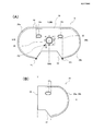
- FIG. 4 is a plan view showing a panel structure of a gas rectifying member used in the airbag device according to the first embodiment of the present invention.
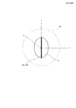
- FIG. 5 is a front view showing the positional relationship between the front panel of the airbag and the gas rectifying member according to the first embodiment of the present invention, and shows the deployed airbag as viewed from the driver side (partially seen through).
- FIG. 6A is a perspective view showing a state in which the airbag according to the first embodiment of the present invention is deployed, and FIG. 6B is an enlarged view of a part of FIG. 6A.
- FIG. 7 is a plan view showing a panel structure of a gas rectifying member used in the airbag device according to the second embodiment of the present invention.
- FIG. 8 is a plan view showing a panel structure of a gas rectifying member used in the airbag device according to the third embodiment of the present invention.
- FIG. 9 is a plan view showing a panel structure of a gas rectifying member used in the airbag device according to the fourth embodiment of the present invention.
- FIG. 7 is a plan view showing a panel structure of a gas rectifying member used in the airbag device according to the second embodiment of the present invention.
- FIG. 8 is a plan view showing a panel structure of a gas rectifying member used in the airbag device according to the third embodiment of the present invention.
- FIG. 9 is a plan view showing a panel
- FIG. 10 is a plan view showing a panel structure of a gas rectifying member used in the airbag device according to the fifth embodiment of the present invention.
- FIG. 11 is a plan view showing a panel structure of a gas rectifying member used in the airbag device according to the sixth embodiment of the present invention.
- FIG. 12 is a plan view showing a panel structure of a gas rectifying member used in the airbag device according to the seventh embodiment of the present invention.
- FIG. 1 is a plan view showing an external shape of a steering wheel 12 to which the airbag device 10 according to the present invention can be applied.
- FIG. 2 is a side view showing a state in which the airbag device 10 according to the present invention is operated and the airbag 16 is deployed.
- the airbag device 10 according to the present invention is housed near the center of the steering wheel 12. Note that “12 o'clock”, “3 o'clock”, “6 o'clock”, and “9 o'clock” are when the steering wheel (or the surface perpendicular to the deployment direction of the airbag) is viewed from the driver side. Corresponds to the position indicating the time.
- the airbag device 10 includes a gas generator 14 that generates an expansion gas; an airbag 16 that restrains an occupant by expanding and deploying with the expansion gas; and an occupant of the gas generator inside the airbag 16. It is provided so as to cover the D side, and includes a gas rectifying member 18 that controls the flow of expanding gas.
- FIG. 3 is a plan view showing a panel structure of an airbag 16 adopted in the airbag device 10 according to the first embodiment of the present invention.
- the airbag 16 includes a circular front panel 20 located on the occupant D side, a circular back panel 22 located on the gas generator 14 side, and a side panel 24 connected to the outer periphery of the front panel 20 and the back panel 22. It is composed of and.
- the front panel 20 is formed larger than the back panel 22.
- the outer peripheral sewn portion 20a of the front panel 20 is connected to the sewn portion 24a of the side panel 24 by sewing, and the outer peripheral sewn portion 22a of the back panel 22 is connected to the sewn portion 24b of the side panel 24 by sewing.
- a connecting hole 26 into which the gas generator 14 is inserted is formed in the center of the back panel 22. Further, a connecting portion 28 with the rectifying member 18 is formed on the outside of the connecting hole 26.
- FIG. 4 is a plan view showing a panel structure of a rectifying member 18 adopted in the airbag device 10 according to the first embodiment of the present invention.
- (A) shows the panel 30 before sewing
- (B) shows the panel 30 in a sewn state.
- the gas rectifying member 18 is formed from a symmetrical panel 30 and is oriented in the 6 o'clock direction when the surface parallel to the rim of the steering wheel 12 is regarded as a clock face.
- a downward opening portion 32 for discharging the expansion gas is formed.
- the left and right edges of the panel 30 are sewn (36a, 36b) so as to cover the occupant D side of the gas generator 14 (see FIG. 6).
- symmetrical means symmetrical with respect to the line (Y-axis) connecting the 12 o'clock position and the 6 o'clock position.
- occupant side means a direction perpendicular to the surface including the rim of the steering wheel 12 and a direction slightly inclined from the vertical direction.
- the flat panel 30 before sewing is aligned with the direction in which it is actually installed with respect to the steering wheel 12, and the line (Y-axis) connecting 12 o'clock and 6 o'clock and 3
- the line connecting time and 9 o'clock X axis
- the upper right area between 12 o'clock and 3 o'clock and the upper left area between 9 o'clock and 12 o'clock A first opening 34b and a second opening 34a, which are oval-shaped, are formed therein.
- the directions of 12 o'clock, 3 o'clock, 6 o'clock, and 9 o'clock are the positions when the steering wheel is regarded as the dial of the clock, but the direction of the steering when the vehicle goes straight is the reference.
- the upward or traveling direction is 12 o'clock
- the position rotated 90 degrees clockwise with respect to this 12 o'clock position is 3 o'clock
- the position rotated 180 degrees is 6 o'clock
- the position rotated 270 degrees is 9 o'clock.
- a connecting hole 35 into which the gas generator 14 is inserted is formed in the center of the panel 30 for forming the gas rectifying member 18. Further, a connecting portion 39 with the back panel 22 is formed on the outside of the connecting hole 35.
- the lower opening portion 32 of the panel 30 is formed as a notch, and the edge portion of the notch 32 is not sewn.
- the notch forming the downward opening portion 32 is formed in a trapezoidal shape having a wide edge on the opposite side to the 12 o'clock position.
- an upper opening portion 38 having an opening area smaller than that of the lower opening portion 32 can be formed.
- the upper portion may be closed by sewing without forming the upper opening portion 38.
- the gas rectifying member 18 and the back panel 22 of the airbag 16 are connected to each other at connecting portions (28, 39) near the outer periphery of the gas generator 14.
- the angle ⁇ formed by the straight line connecting the lower corner portion P1 of the trapezoidal notch 32 and the closest position P2 of the connecting portion 39 and the straight line (X-axis) in the 3 o'clock to 9 o'clock direction is It is 110 ° to 170 °, preferably 120 ° to 160 °.
- the panel 30 is folded along the Y axis (12 o'clock to 6 o'clock direction) passing through the center and sewn along the sewing lines 36a and 36b. ing.
- FIG. 5 is a front view showing the positional relationship between the front panel 20 of the airbag 16 and the gas rectifying member 18, and shows a state (partially seen through) of the deployed airbag 16 as viewed from the driver D side.
- the center position of the front panel 20 of the airbag 16 in the housed state and the gas rectifying member 18 It is preferable that the center position C coincides with the center position C, but at least the deviations in the X direction and the Y direction are ⁇ 30 mm or less.
- the gas rectifying member 18 is folded and accommodated so as to be in contact with the front panel 20.
- FIG. 6A is a perspective view showing a state in which the airbag 16 according to the first embodiment of the present invention is deployed
- FIG. 6B is an enlarged view of a part of FIG. 6A.
- a cover 42 is provided on the occupant D side of the airbag 16 in the housed state to open the hinge 42a as a fulcrum when the airbag 16 is deployed.
- At least a part of the first and second openings 34b and 34a is configured to be in a position protruding toward the occupant D side from the surface (hinge 42a) of the cover 42 when the airbag 16 is deployed.
- the lower opening portion 32 similarly, at least a part of the lower opening portion 32 is positioned so as to protrude toward the occupant D side from the surface (hinge 42a) of the cover 42 when the airbag 16 is deployed. It is configured in.
- the airbag 16 when the airbag device 10 is activated, the gas released from the gas generator 14 flows into the gas rectifying member 18 before being filled in the entire airbag 16. After that, a large amount of expansion gas flows out from the downward opening 32 into the airbag 16 and a part of the expansion gas flows out from the first opening 34b and the second opening 34a into the airbag 16. .. Therefore, the airbag 16 can be quickly deployed in the direction of 6 o'clock at the initial stage of deployment, can enter between the occupant (driver D) and the steering wheel 12, and quickly restrain the abdomen of the occupant D. ..
- each embodiment is a modification of the panel structure of the gas rectifying member 18 of the first embodiment described above, the first embodiment Only the differences from and will be described. That is, for the components corresponding to the first embodiment described above, the last two digits are the same code and only the third digit is changed, and in the case of substantially the same function and structure, duplicate explanations are omitted. To do.
- FIG. 7 is a plan view showing the structure of the panel 130 of the gas rectifying member 118 adopted in the airbag device according to the second embodiment of the present invention.
- the trapezoidal shape of the downward opening portion 132 is horizontally long, and the angle ⁇ is larger than that in the first embodiment.
- one panel 140 is interposed between the left and right edge portions 136a and 136b of the panel 130 to increase the thickness of the gas rectifying member 118 in the X-axis direction.
- FIG. 8 is a plan view showing the structure of the panel 230 of the gas rectifying member 218 used in the airbag device according to the third embodiment of the present invention.
- the trapezoidal shape of the downward opening portion 232 is horizontally long, and the angle ⁇ is larger than that in the first embodiment.
- the first and second openings 234b and 234a are not oval but are completely circular.
- FIG. 9 is a plan view showing the structure of the panel 330 of the gas rectifying member 318 used in the airbag device according to the fourth embodiment of the present invention.
- the shape of the panel 330 itself is completely the same as that of the first embodiment, but the sewing lines 336a and 336b are formed only by straight lines instead of curved lines.
- FIG. 10 is a plan view showing the structure of the panel 430 of the gas rectifying member 418 used in the airbag device according to the fifth embodiment of the present invention.
- a panel 430 having an appearance shape different from that of the other embodiments is adopted, and the length (height) in the Y direction is relatively large. Therefore, when the airbag 16 is deployed, the first and second openings 434b and 434a project further toward the occupant D side than the cover 42 (see FIG. 6).
- FIG. 11 is a plan view showing the structure of the panel 530 of the gas rectifying member 518 adopted in the airbag device according to the sixth embodiment of the present invention.
- the downward opening portion 532 is formed extremely horizontally long, and therefore the angle ⁇ is very large. Therefore, the opening area of the lower opening portion 532 formed after sewing becomes large.
- FIG. 12 is a plan view showing a panel structure of a gas rectifying member 618 used in the airbag device according to the seventh embodiment of the present invention.
- (A) shows the panel 630 before sewing
- (B) shows the panel 630 in the sewn state.
- This embodiment is similar to the third embodiment shown in FIG. 8, except for the sewing portion 636 on the outer circumference of the panel 630.
- the sewing line 636 on the outer peripheral portion of the panel 630 is continuous at the 12 o'clock position without interruption. Therefore, as shown in FIG. (B), the 12 o'clock side (upper portion) of the gas rectifying member 618 after sewing is completely closed. As a result, the expansion gas released from the inflator flows out to the inside of the airbag only from the downward opening portion 632 and the first and second openings 634b and 634a.
Abstract
Description
前記ガス整流部材は、ステアリングホイールのリムに平行な面を時計の文字盤に見立てたときに、12時と6時を結ぶ線(X軸)に対して左右対称な部分を含んだ平面状のパネルから成形され、前記パネルの左右縁部同士を縫製することで、6時の方向に前記膨張ガスを排出する下方開放部が形成され、且つ前記ガス発生器の乗員側を覆う構成である。
そして、縫製前の前記パネルを、前記ステアリングホイールに対して実際に設置する向きに合わせ、前記X軸と、3時と9時とを結ぶ線(Y軸)とによって仮想的に4分割したときに、12時と3時との間の右上部領域と、9時と12時との間の左上部領域とに、第1の開口部と第2の開口部が各々形成されている。 In order to achieve the above object, the airbag device according to the present invention is an airbag device housed in a steering wheel of a vehicle and is a gas generator that generates an expansion gas; and is expanded and deployed by the expansion gas. It is provided with an airbag that restrains an occupant with a gas, and a gas rectifying member that is provided inside the airbag so as to cover the occupant side of the gas generator and controls the flow of the expanded gas.
The gas rectifying member is a flat surface including a portion symmetrical with respect to the line (X-axis) connecting 12 o'clock and 6 o'clock when the surface parallel to the rim of the steering wheel is regarded as a clock face. By molding from the panel and sewing the left and right edges of the panel to each other, a downward open portion for discharging the expansion gas is formed at 6 o'clock, and the gas generator is covered on the occupant side.
Then, when the panel before sewing is aligned with the direction in which it is actually installed with respect to the steering wheel, and is virtually divided into four by a line (Y axis) connecting the X axis and 3 o'clock and 9 o'clock. In addition, a first opening and a second opening are formed in the upper right region between 12 o'clock and 3 o'clock and the upper left region between 9 o'clock and 12 o'clock, respectively.
発明者による実験の結果、上記のような角度θの設定とすることで、良好な展開挙動を得ることができた。 The downward opening portion may be formed as a notch in the panel, and the edge portion of the notch may not be sewn. The notch forming the downward opening portion is a state in which the left and right edge portions of the panel are in a state before sewing, and the edge portion on the side opposite to the 12 o'clock position is the edge portion on the side close to the 12 o'clock position. It can be molded into a wider trapezoidal shape. Here, the angle θ formed by the straight line connecting the lower corner portion of the trapezoidal notch and the connecting portion and the straight line in the 3 o'clock to 9 o'clock direction is 110 ° to 170 °, and further. , 120 ° to 160 ° is preferable.
As a result of the experiment by the inventor, good deployment behavior could be obtained by setting the angle θ as described above.
本発明に係るエアバッグ装置10は、ステアリングホイール12の中心付近に収容される。なお、「12時」、「3時」、「6時」、「9時」とは、ステアリングホイール(あるいは、エアバッグの展開方向と垂直な面)をドライバ側から見たときに、時計の時刻を示す位置に対応する。 Hereinafter, the airbag device according to the embodiment of the present invention will be described with reference to the accompanying drawings. FIG. 1 is a plan view showing an external shape of a
The
バックパネル22の中心には、ガス発生器14が挿入される連結孔26が形成されている。また、連結孔26の外側には、整流部材18との連結部28が形成されている。 The outer peripheral sewn
A connecting
発明者による実験の結果、上記のような角度θの設定とすることで、良好な展開挙動を得ることができた。 The
As a result of the experiment by the inventor, good deployment behavior could be obtained by setting the angle θ as described above.
また、エアバッグ16の収容状態において、ガス整流部材18がフロントパネル20と接するように折り畳まれ、収容される。 FIG. 5 is a front view showing the positional relationship between the
Further, in the state of accommodating the
Claims (15)
- 車両のステアリングホイールに収容されるエアバッグ装置であって、
膨張ガスを発生するガス発生器と;
前記膨張ガスによって膨張展開することで乗員を拘束するエアバッグと;
前記エアバッグの内部において、前記ガス発生器の前記乗員側を覆うように設けられ、前記膨張ガスの流れを制御するガス整流部材と;を備え、
前記ガス整流部材は、ステアリングホイールのリムに平行な面を時計の文字盤に見立てたときに、12時と6時を結ぶ線(X軸)に対して左右対称な部分を含んだ平面状のパネルから成形され、前記パネルの左右縁部同士を縫製することで、6時の方向に前記膨張ガスを排出する下方開放部が形成され、且つ前記ガス発生器の乗員側を覆う構成であり、
縫製前の前記パネルを、前記ステアリングホイールに対して実際に設置する向きに合わせ、前記X軸と、3時と9時とを結ぶ線(Y軸)とによって仮想的に4分割したときに、12時と3時との間の右上部領域と、9時と12時との間の左上部領域とに、第1の開口部と第2の開口部が各々形成されていることを特徴とするエアバッグ装置。 An airbag device housed in the steering wheel of a vehicle.
With a gas generator that generates expansion gas;
With an airbag that restrains the occupant by expanding and deploying with the expansion gas;
A gas rectifying member provided inside the airbag so as to cover the occupant side of the gas generator and controlling the flow of the expanded gas;
The gas rectifying member is a flat surface including a portion symmetrical with respect to the line (X-axis) connecting 12 o'clock and 6 o'clock when the surface parallel to the rim of the steering wheel is regarded as a clock face. By molding from the panel and sewing the left and right edges of the panel to each other, a downward open portion for discharging the expansion gas is formed at 6 o'clock, and the gas generator is covered on the occupant side.
When the panel before sewing is virtually divided into four by the X-axis and the line connecting 3 o'clock and 9 o'clock (Y-axis) according to the direction in which the panel is actually installed with respect to the steering wheel. It is characterized in that a first opening and a second opening are formed in the upper right region between 12 o'clock and 3 o'clock and the upper left region between 9 o'clock and 12 o'clock, respectively. Airbag device. - 前記下方開放部は、前記パネルの切り欠きとして成形され、当該切り欠きの縁部は縫製されないことを特徴とする請求項1に記載のエアバッグ装置。 The airbag device according to claim 1, wherein the lower opening portion is formed as a notch in the panel, and the edge portion of the notch is not sewn.
- 前記下方開放部を形成する前記切り欠きは、前記パネルの左右縁部同士の縫製前の状態で、前記12時の位置と反対側の縁部が、前記12時の位置に近い側の縁部よりも広い台形状に成形されていることを特徴とする請求項2に記載のエアバッグ装置。 The notch forming the downward opening portion is a state in which the left and right edge portions of the panel are in a state before sewing, and the edge portion on the side opposite to the 12 o'clock position is the edge portion on the side close to the 12 o'clock position. The airbag device according to claim 2, wherein the airbag device is formed into a wider trapezoidal shape.
- 前記台形状の前記切り欠きの下側の角部と前記連結部とを結んだ直線と、前記3時-9時方向の直線とがなす角度θが110°~170°であることを特徴とする請求項3に記載のエアバッグ装置。 The feature is that the angle θ formed by the straight line connecting the lower corner portion of the trapezoidal notch and the connecting portion and the straight line in the 3 o'clock to 9 o'clock direction is 110 ° to 170 °. The airbag device according to claim 3.
- 前記角度θが、120°~160°であることを特徴とする請求項4に記載のエアバッグ装置。 The airbag device according to claim 4, wherein the angle θ is 120 ° to 160 °.
- 前記12時の方向に前記膨張ガスを排出する上方開放部が更に形成され、当該上方開放部は、前記下方開放部よりも小さい開口面積を有することを特徴とする請求項1乃至5の何れか1項に記載のエアバッグ装置。 Any of claims 1 to 5, wherein an upper opening portion for discharging the expansion gas is further formed in the 12 o'clock direction, and the upper opening portion has an opening area smaller than that of the lower opening portion. The airbag device according to item 1.
- 前記ガス整流部材と前記エアバッグとは、前記ガス発生器の外周付近の連結部において互いに連結されていることを特徴とする請求項1乃至6の何れか1項に記載のエアバッグ装置。 The airbag device according to any one of claims 1 to 6, wherein the gas rectifying member and the airbag are connected to each other at a connecting portion near the outer periphery of the gas generator.
- 前記第1及び第2の開口部の面積は、前記下方開放部の開口面積よりも小さいことを特徴とする請求項1乃至7の何れか1項に記載のエアバッグ装置。 The airbag device according to any one of claims 1 to 7, wherein the area of the first and second openings is smaller than the opening area of the lower opening.
- 前記第1及び第2の開口部の面積は、840mm2~4800mm2であることを特徴とする請求項1乃至8の何れか1項に記載のエアバッグ装置。 The areas of the first and second openings, the air bag device according to any one of claims 1 to 8, characterized in that it is 840 mm 2 ~ 4800 mm 2.
- 収容状態の前記エアバッグの乗員側表面を覆うカバーが設けられ、
前記カバーは、前記エアバッグが展開したときに開放する構造であり、
前記第1及び第2の開口部の少なくとも一部は、前記エアバッグが展開したときに、前記カバーの表面よりも乗員側に突出した位置にあることを特徴とする請求項1乃至9の何れか1項に記載のエアバッグ装置。 A cover is provided to cover the occupant side surface of the airbag in the stored state.
The cover has a structure that opens when the airbag is deployed.
Any of claims 1 to 9, wherein at least a part of the first and second openings is located at a position protruding toward the occupant side with respect to the surface of the cover when the airbag is deployed. The airbag device according to item 1. - 収容状態の前記エアバッグの乗員側表面を覆うカバーが設けられ、
前記カバーは、前記エアバッグが展開したときに開放する構造であり、
前記下方開放部の少なくとも一部は、前記エアバッグが展開したときに、前記カバーの表面よりも乗員側に突出した位置にあることを特徴とする請求項1乃至10の何れか1項に記載のエアバッグ装置。 A cover is provided to cover the occupant side surface of the airbag in the stored state.
The cover has a structure that opens when the airbag is deployed.
The invention according to any one of claims 1 to 10, wherein at least a part of the downward opening portion is located at a position protruding toward the occupant side from the surface of the cover when the airbag is deployed. Airbag device. - 前記エアバッグは、乗員側に位置するフロントパネルと、前記ガス発生器側に位置するバックパネルと、当該フロントパネルとバックパネルとを連結するサイドパネルとを含むことを特徴とする請求項1乃至11の何れか1項に記載のエアバッグ装置。 Claims 1 to 1, wherein the airbag includes a front panel located on the occupant side, a back panel located on the gas generator side, and a side panel connecting the front panel and the back panel. The airbag device according to any one of 11.
- 前記3時-9時の方向をY軸方向としたときに、収容状態にある前記エアバッグの前記フロントパネルの中心位置と前記ガス整流部材の中心位置とのY軸方向におけるずれが±30mm以下であることを特徴とする請求項12に記載のエアバッグ装置。 When the 3 o'clock to 9 o'clock direction is the Y-axis direction, the deviation between the center position of the front panel of the airbag in the housed state and the center position of the gas rectifying member in the Y-axis direction is ± 30 mm or less. The airbag device according to claim 12, wherein the airbag device is characterized by the above.
- 前記12時-6時の方向をX軸方向としたときに、収容状態にある前記エアバッグの前記フロントパネルの中心位置と前記ガス整流部材の中心位置とのX軸方向におけるずれが±30mm以下であることを特徴とする請求項12又は13に記載のエアバッグ装置。 When the 12 o'clock to 6 o'clock direction is the X-axis direction, the deviation between the center position of the front panel of the airbag in the housed state and the center position of the gas rectifying member in the X-axis direction is ± 30 mm or less. The airbag device according to claim 12 or 13, wherein the airbag device is characterized by the above.
- 前記エアバッグの収容状態において、前記ガス整流部材が前記フロントパネルと接するように配置されることを特徴とする請求項12乃至14の何れか1項に記載のエアバッグ装置。 The airbag device according to any one of claims 12 to 14, wherein the gas rectifying member is arranged so as to be in contact with the front panel in the stored state of the airbag.
Priority Applications (5)
| Application Number | Priority Date | Filing Date | Title |
|---|---|---|---|
| KR1020217037720A KR102609538B1 (en) | 2019-04-25 | 2020-03-24 | driver airbag device |
| CN202080028575.8A CN113677568B (en) | 2019-04-25 | 2020-03-24 | Driver airbag device |
| EP20794420.8A EP3960550B1 (en) | 2019-04-25 | 2020-03-24 | Driver airbag device |
| US17/594,580 US11752964B2 (en) | 2019-04-25 | 2020-03-24 | Driver airbag device |
| JP2021515890A JP7291210B2 (en) | 2019-04-25 | 2020-03-24 | Driver airbag device |
Applications Claiming Priority (2)
| Application Number | Priority Date | Filing Date | Title |
|---|---|---|---|
| JP2019-084758 | 2019-04-25 | ||
| JP2019084758 | 2019-04-25 |
Publications (1)
| Publication Number | Publication Date |
|---|---|
| WO2020217824A1 true WO2020217824A1 (en) | 2020-10-29 |
Family
ID=72942539
Family Applications (1)
| Application Number | Title | Priority Date | Filing Date |
|---|---|---|---|
| PCT/JP2020/013132 WO2020217824A1 (en) | 2019-04-25 | 2020-03-24 | Driver airbag device |
Country Status (6)
| Country | Link |
|---|---|
| US (1) | US11752964B2 (en) |
| EP (1) | EP3960550B1 (en) |
| JP (1) | JP7291210B2 (en) |
| KR (1) | KR102609538B1 (en) |
| CN (1) | CN113677568B (en) |
| WO (1) | WO2020217824A1 (en) |
Families Citing this family (1)
| Publication number | Priority date | Publication date | Assignee | Title |
|---|---|---|---|---|
| JP7357073B2 (en) * | 2019-12-05 | 2023-10-05 | オートリブ ディベロップメント エービー | air bag device |
Citations (5)
| Publication number | Priority date | Publication date | Assignee | Title |
|---|---|---|---|---|
| JP2000085512A (en) * | 1998-09-08 | 2000-03-28 | Denso Corp | Air bag module |
| JP2001080440A (en) * | 1999-07-15 | 2001-03-27 | Takata Corp | Air bag, air bag device and steering |
| JP2003320921A (en) * | 2002-04-26 | 2003-11-11 | Breed Automotive Technology Inc | Flow straightener of air bag pocket for front passenger |
| US20050073139A1 (en) * | 2003-10-06 | 2005-04-07 | Trw Vehicle Safety Systems Inc. | Inflatable vehicle occupant protection device with inflation fluid deflector |
| JP2006297958A (en) * | 2005-04-15 | 2006-11-02 | Takata Corp | Air bag and air bag device |
Family Cites Families (32)
| Publication number | Priority date | Publication date | Assignee | Title |
|---|---|---|---|---|
| JPS5216140U (en) * | 1975-07-23 | 1977-02-04 | ||
| JPH0948307A (en) * | 1995-08-11 | 1997-02-18 | Denso Corp | Manufacture of air bag |
| JPH10226294A (en) * | 1997-02-17 | 1998-08-25 | Toyo Tire & Rubber Co Ltd | Air bag for vehicle |
| JP3577208B2 (en) * | 1997-12-09 | 2004-10-13 | トヨタ自動車株式会社 | Passenger airbag device |
| DE19858690A1 (en) * | 1998-12-18 | 2000-06-21 | Delphi Automotive Systems Gmbh | Airbag |
| DE10011066A1 (en) * | 2000-03-07 | 2001-09-13 | Delphi Tech Inc | Airbag module for motor vehicle has deflection pocket in region of airbag's inlet opening and consisting of lower material layer with through-opening aligned with inlet opening and at least partially covered by upper layer |
| DE10030488A1 (en) * | 2000-06-21 | 2002-01-03 | Delphi Tech Inc | air bag |
| JP2003170796A (en) * | 2001-12-06 | 2003-06-17 | Takata Corp | Airbag |
| JP4100129B2 (en) * | 2002-10-28 | 2008-06-11 | タカタ株式会社 | Airbag device |
| JP2006248511A (en) * | 2005-02-09 | 2006-09-21 | Takata Corp | Airbag and airbag device |
| US7445238B2 (en) * | 2005-05-06 | 2008-11-04 | Tk Holdings Inc. | Occupant protection apparatus |
| JP2009113502A (en) * | 2006-02-09 | 2009-05-28 | Takata Corp | Air bag and air bag device |
| EP1864871B1 (en) * | 2006-06-02 | 2008-12-03 | Toyoda Gosei Co., Ltd. | Airbag apparatus |
| JP5641637B2 (en) * | 2009-12-23 | 2014-12-17 | タカタ株式会社 | Air bag and air bag device |
| JP5206707B2 (en) * | 2010-02-23 | 2013-06-12 | 豊田合成株式会社 | Airbag device for passenger seat |
| JP5883613B2 (en) * | 2011-10-20 | 2016-03-15 | 芦森工業株式会社 | Airbag device |
| JP5664567B2 (en) * | 2012-01-31 | 2015-02-04 | 豊田合成株式会社 | Airbag device for steering wheel |
| WO2013114591A1 (en) * | 2012-02-01 | 2013-08-08 | トヨタ自動車株式会社 | Vehicle side airbag device |
| JP6143542B2 (en) * | 2013-05-13 | 2017-06-07 | 芦森工業株式会社 | Airbag device |
| JP5880489B2 (en) * | 2013-06-25 | 2016-03-09 | トヨタ自動車株式会社 | Airbag device for driver's seat |
| US9283921B2 (en) * | 2013-11-21 | 2016-03-15 | Ford Global Technologies, Llc | Driver airbag module having multiple deployment paths |
| JP6422738B2 (en) * | 2014-10-31 | 2018-11-14 | 芦森工業株式会社 | Airbag device |
| JP6726543B2 (en) * | 2016-07-01 | 2020-07-22 | 日本プラスト株式会社 | Airbag |
| JP2018020737A (en) * | 2016-08-05 | 2018-02-08 | タカタ株式会社 | Airbag for driver seat, airbag device for driver seat and steering wheel |
| JP6806005B2 (en) * | 2017-08-25 | 2020-12-23 | 豊田合成株式会社 | Airbag |
| JP6798954B2 (en) * | 2017-09-14 | 2020-12-09 | 本田技研工業株式会社 | Airbag device |
| CN111094078B (en) * | 2017-10-05 | 2024-02-13 | 奥托立夫开发公司 | Airbag device |
| CN112236335B (en) * | 2018-06-04 | 2022-10-18 | 奥托立夫开发公司 | Safety air bag device for vehicle driver's seat |
| JP7316364B2 (en) * | 2019-09-17 | 2023-07-27 | オートリブ ディベロップメント エービー | Airbag device for driver's seat |
| JP7215453B2 (en) * | 2020-03-31 | 2023-01-31 | 豊田合成株式会社 | Airbag device for driver's seat |
| US11472363B2 (en) * | 2020-04-13 | 2022-10-18 | Autoliv Development Ab | Driver's side airbag device |
| JP7400764B2 (en) * | 2021-03-29 | 2023-12-19 | 豊田合成株式会社 | air bag device |
-
2020
- 2020-03-24 WO PCT/JP2020/013132 patent/WO2020217824A1/en unknown
- 2020-03-24 EP EP20794420.8A patent/EP3960550B1/en active Active
- 2020-03-24 JP JP2021515890A patent/JP7291210B2/en active Active
- 2020-03-24 US US17/594,580 patent/US11752964B2/en active Active
- 2020-03-24 KR KR1020217037720A patent/KR102609538B1/en active IP Right Grant
- 2020-03-24 CN CN202080028575.8A patent/CN113677568B/en active Active
Patent Citations (5)
| Publication number | Priority date | Publication date | Assignee | Title |
|---|---|---|---|---|
| JP2000085512A (en) * | 1998-09-08 | 2000-03-28 | Denso Corp | Air bag module |
| JP2001080440A (en) * | 1999-07-15 | 2001-03-27 | Takata Corp | Air bag, air bag device and steering |
| JP2003320921A (en) * | 2002-04-26 | 2003-11-11 | Breed Automotive Technology Inc | Flow straightener of air bag pocket for front passenger |
| US20050073139A1 (en) * | 2003-10-06 | 2005-04-07 | Trw Vehicle Safety Systems Inc. | Inflatable vehicle occupant protection device with inflation fluid deflector |
| JP2006297958A (en) * | 2005-04-15 | 2006-11-02 | Takata Corp | Air bag and air bag device |
Also Published As
| Publication number | Publication date |
|---|---|
| JP7291210B2 (en) | 2023-06-14 |
| KR102609538B1 (en) | 2023-12-04 |
| CN113677568A (en) | 2021-11-19 |
| CN113677568B (en) | 2023-11-24 |
| EP3960550A1 (en) | 2022-03-02 |
| JPWO2020217824A1 (en) | 2020-10-29 |
| EP3960550B1 (en) | 2024-03-13 |
| US20220203920A1 (en) | 2022-06-30 |
| US11752964B2 (en) | 2023-09-12 |
| KR20210153698A (en) | 2021-12-17 |
| EP3960550A4 (en) | 2023-01-25 |
Similar Documents
| Publication | Publication Date | Title |
|---|---|---|
| EP1992526B1 (en) | Tether mounting method for airbag device, and airbag device | |
| US20120074677A1 (en) | Airbag, airbag device, and method for sewing lid member of airbag | |
| WO2010026970A1 (en) | Knee airbag device for vehicle | |
| JP6710756B2 (en) | Airbag device | |
| JP7054422B2 (en) | Airbag device | |
| US7988189B2 (en) | Air bag cover and air bag device | |
| WO2020217824A1 (en) | Driver airbag device | |
| JP6224932B2 (en) | Air bag and air bag device | |
| JP6754347B2 (en) | Airbag device | |
| JP6981382B2 (en) | Airbag | |
| JP4376677B2 (en) | Airbag device and airbag folding method | |
| JP7412570B2 (en) | air bag device | |
| JP2013123974A (en) | Module cover and airbag device | |
| JP2014213749A (en) | Air bag | |
| JP7425227B2 (en) | air bag device | |
| WO2024070721A1 (en) | Pedestrian protection airbag apparatus | |
| KR102443541B1 (en) | Air bag device | |
| JP5318722B2 (en) | Air bag and air bag device | |
| JP6995611B2 (en) | Knee airbag and knee airbag device | |
| KR100295994B1 (en) | Air bag having a vent control means and manufacturing methode thereof | |
| JP2506253Y2 (en) | Airbag device | |
| JP2022165710A (en) | Air bag and air bag device | |
| JP2005335652A (en) | Air bag device, and manufacturing method of air bag for vehicle | |
| JP2005088621A (en) | Welded portion structure for vehicular air bag device | |
| JPH04339048A (en) | Air bag grid fitting structure |
Legal Events
| Date | Code | Title | Description |
|---|---|---|---|
| 121 | Ep: the epo has been informed by wipo that ep was designated in this application |
Ref document number: 20794420 Country of ref document: EP Kind code of ref document: A1 |
|
| ENP | Entry into the national phase |
Ref document number: 2021515890 Country of ref document: JP Kind code of ref document: A |
|
| NENP | Non-entry into the national phase |
Ref country code: DE |
|
| ENP | Entry into the national phase |
Ref document number: 20217037720 Country of ref document: KR Kind code of ref document: A |
|
| ENP | Entry into the national phase |
Ref document number: 2020794420 Country of ref document: EP Effective date: 20211125 |