WO2020217600A1 - Cleaning device, imaging unit with cleaning device, and cleaning method - Google Patents
Cleaning device, imaging unit with cleaning device, and cleaning method Download PDFInfo
- Publication number
- WO2020217600A1 WO2020217600A1 PCT/JP2020/000851 JP2020000851W WO2020217600A1 WO 2020217600 A1 WO2020217600 A1 WO 2020217600A1 JP 2020000851 W JP2020000851 W JP 2020000851W WO 2020217600 A1 WO2020217600 A1 WO 2020217600A1
- Authority
- WO
- WIPO (PCT)
- Prior art keywords
- cleaning
- unit
- foreign matter
- protective cover
- resonance frequency
- Prior art date
Links
Images


Classifications
-
- H—ELECTRICITY
- H04—ELECTRIC COMMUNICATION TECHNIQUE
- H04N—PICTORIAL COMMUNICATION, e.g. TELEVISION
- H04N23/00—Cameras or camera modules comprising electronic image sensors; Control thereof
- H04N23/80—Camera processing pipelines; Components thereof
- H04N23/81—Camera processing pipelines; Components thereof for suppressing or minimising disturbance in the image signal generation
- H04N23/811—Camera processing pipelines; Components thereof for suppressing or minimising disturbance in the image signal generation by dust removal, e.g. from surfaces of the image sensor or processing of the image signal output by the electronic image sensor
-
- B—PERFORMING OPERATIONS; TRANSPORTING
- B08—CLEANING
- B08B—CLEANING IN GENERAL; PREVENTION OF FOULING IN GENERAL
- B08B7/00—Cleaning by methods not provided for in a single other subclass or a single group in this subclass
- B08B7/02—Cleaning by methods not provided for in a single other subclass or a single group in this subclass by distortion, beating, or vibration of the surface to be cleaned
-
- B—PERFORMING OPERATIONS; TRANSPORTING
- B08—CLEANING
- B08B—CLEANING IN GENERAL; PREVENTION OF FOULING IN GENERAL
- B08B3/00—Cleaning by methods involving the use or presence of liquid or steam
- B08B3/04—Cleaning involving contact with liquid
- B08B3/10—Cleaning involving contact with liquid with additional treatment of the liquid or of the object being cleaned, e.g. by heat, by electricity or by vibration
- B08B3/12—Cleaning involving contact with liquid with additional treatment of the liquid or of the object being cleaned, e.g. by heat, by electricity or by vibration by sonic or ultrasonic vibrations
-
- B—PERFORMING OPERATIONS; TRANSPORTING
- B08—CLEANING
- B08B—CLEANING IN GENERAL; PREVENTION OF FOULING IN GENERAL
- B08B7/00—Cleaning by methods not provided for in a single other subclass or a single group in this subclass
- B08B7/0028—Cleaning by methods not provided for in a single other subclass or a single group in this subclass by adhesive surfaces
-
- B—PERFORMING OPERATIONS; TRANSPORTING
- B08—CLEANING
- B08B—CLEANING IN GENERAL; PREVENTION OF FOULING IN GENERAL
- B08B7/00—Cleaning by methods not provided for in a single other subclass or a single group in this subclass
- B08B7/02—Cleaning by methods not provided for in a single other subclass or a single group in this subclass by distortion, beating, or vibration of the surface to be cleaned
- B08B7/026—Using sound waves
- B08B7/028—Using ultrasounds
-
- B—PERFORMING OPERATIONS; TRANSPORTING
- B60—VEHICLES IN GENERAL
- B60S—SERVICING, CLEANING, REPAIRING, SUPPORTING, LIFTING, OR MANOEUVRING OF VEHICLES, NOT OTHERWISE PROVIDED FOR
- B60S1/00—Cleaning of vehicles
- B60S1/02—Cleaning windscreens, windows or optical devices
- B60S1/46—Cleaning windscreens, windows or optical devices using liquid; Windscreen washers
- B60S1/48—Liquid supply therefor
- B60S1/52—Arrangement of nozzles; Liquid spreading means
-
- B—PERFORMING OPERATIONS; TRANSPORTING
- B60—VEHICLES IN GENERAL
- B60S—SERVICING, CLEANING, REPAIRING, SUPPORTING, LIFTING, OR MANOEUVRING OF VEHICLES, NOT OTHERWISE PROVIDED FOR
- B60S1/00—Cleaning of vehicles
- B60S1/02—Cleaning windscreens, windows or optical devices
- B60S1/56—Cleaning windscreens, windows or optical devices specially adapted for cleaning other parts or devices than front windows or windscreens
- B60S1/60—Cleaning windscreens, windows or optical devices specially adapted for cleaning other parts or devices than front windows or windscreens for signalling devices, e.g. reflectors
-
- G—PHYSICS
- G02—OPTICS
- G02B—OPTICAL ELEMENTS, SYSTEMS OR APPARATUS
- G02B27/00—Optical systems or apparatus not provided for by any of the groups G02B1/00 - G02B26/00, G02B30/00
- G02B27/0006—Optical systems or apparatus not provided for by any of the groups G02B1/00 - G02B26/00, G02B30/00 with means to keep optical surfaces clean, e.g. by preventing or removing dirt, stains, contamination, condensation
-
- G—PHYSICS
- G03—PHOTOGRAPHY; CINEMATOGRAPHY; ANALOGOUS TECHNIQUES USING WAVES OTHER THAN OPTICAL WAVES; ELECTROGRAPHY; HOLOGRAPHY
- G03B—APPARATUS OR ARRANGEMENTS FOR TAKING PHOTOGRAPHS OR FOR PROJECTING OR VIEWING THEM; APPARATUS OR ARRANGEMENTS EMPLOYING ANALOGOUS TECHNIQUES USING WAVES OTHER THAN OPTICAL WAVES; ACCESSORIES THEREFOR
- G03B15/00—Special procedures for taking photographs; Apparatus therefor
-
- G—PHYSICS
- G03—PHOTOGRAPHY; CINEMATOGRAPHY; ANALOGOUS TECHNIQUES USING WAVES OTHER THAN OPTICAL WAVES; ELECTROGRAPHY; HOLOGRAPHY
- G03B—APPARATUS OR ARRANGEMENTS FOR TAKING PHOTOGRAPHS OR FOR PROJECTING OR VIEWING THEM; APPARATUS OR ARRANGEMENTS EMPLOYING ANALOGOUS TECHNIQUES USING WAVES OTHER THAN OPTICAL WAVES; ACCESSORIES THEREFOR
- G03B17/00—Details of cameras or camera bodies; Accessories therefor
- G03B17/02—Bodies
-
- H—ELECTRICITY
- H04—ELECTRIC COMMUNICATION TECHNIQUE
- H04N—PICTORIAL COMMUNICATION, e.g. TELEVISION
- H04N23/00—Cameras or camera modules comprising electronic image sensors; Control thereof
- H04N23/50—Constructional details
- H04N23/52—Elements optimising image sensor operation, e.g. for electromagnetic interference [EMI] protection or temperature control by heat transfer or cooling elements
-
- B—PERFORMING OPERATIONS; TRANSPORTING
- B08—CLEANING
- B08B—CLEANING IN GENERAL; PREVENTION OF FOULING IN GENERAL
- B08B3/00—Cleaning by methods involving the use or presence of liquid or steam
- B08B3/04—Cleaning involving contact with liquid
- B08B3/041—Cleaning travelling work
Definitions
- the present invention relates to a cleaning device, an imaging unit including the cleaning device, and a cleaning method.
- Imaging units are provided at the front and rear of the vehicle, and the images captured by the imaging unit are used to control safety devices and to perform automatic driving control. Since such an imaging unit is often provided outside the vehicle, foreign matter such as raindrops, mud, and dust may adhere to the translucent body (lens or protective glass) that covers the outside. When foreign matter adheres to the translucent body, the foreign matter adhered to the image captured by the imaging unit is reflected, and a clear image cannot be obtained.
- a cleaning device has been developed that discriminates foreign matter adhering to the surface of the translucent body and vibrates the translucent body to remove the foreign matter (Patent Document 1). Further, a cleaning device has been developed in which a cleaning liquid is discharged onto the surface of a translucent body to vibrate the translucent body to remove foreign substances (Patent Document 2).
- Patent Document 1 may not be able to remove muddy water or the like only by vibrating the translucent body.
- the water in the muddy water is atomized by vibrating the translucent body, and the muddy water or the like cannot be removed only by vibrating the translucent body due to an increase in the concentration of mud in the muddy water.
- an object of the present invention is to provide a cleaning device capable of performing highly efficient cleaning according to a foreign substance adhering to a translucent body, an imaging unit provided with the cleaning device, and a cleaning method.
- the cleaning device includes a holding unit that holds the image pickup element, a translucent body that is arranged in the field of view of the image pickup element, a vibrating body that vibrates the translucent body, and a driving unit that drives the vibrating body.
- a control unit that controls the drive unit and a detection unit that detects a value related to the impedance of the vibrating body driven by the driving unit are provided, and the control unit has a resonance frequency when the vibrating body is driven by the first voltage. Based on at least two pieces of information, the time change, the time change of the value related to the impedance detected by the detection unit, and the time change of the image captured by the imaging element, it is determined that foreign matter has adhered to the surface of the translucent body. , The surface of the translucent body is cleaned by controlling the vibrating body according to the judgment.
- the imaging unit includes the cleaning device described above.
- the cleaning method includes a holding unit that holds the image pickup element, a translucent body that is arranged in the field of view of the image pickup element, a vibrating body that vibrates the translucent body, and a driving unit that drives the vibrating body.
- a cleaning method for cleaning the surface of the translucent body with a cleaning device including a control unit that controls the drive unit and a detection unit that detects a value related to the impedance of the vibrating body driven by the drive unit, as a search mode.
- control unit determines that foreign matter has adhered to the surface of the translucent body based on at least two pieces of information, and performs highly efficient cleaning according to the foreign matter adhering to the translucent body. Can be done.
- FIG. 1 is a perspective view for explaining the configuration of the imaging unit 100 according to the first embodiment.
- FIG. 2 is a cross-sectional view for explaining the configuration of the imaging unit 100 according to the first embodiment.
- the imaging unit 100 vibrates the housing 1, the transparent protective cover 2 provided on one surface of the housing 1, the cleaning nozzle 3 having an opening 31 for discharging the cleaning liquid (cleaning body) into the protective cover 2, and the protective cover 2. It is provided with a vibrating unit 12 which is a vibrating body and an imaging unit 5 provided inside the protective cover 2.
- the configuration of the housing 1, the protective cover 2, the cleaning nozzle 3, and the vibrating unit 12 excluding the imaging unit 5 from the imaging unit 100 is a cleaning that cleans foreign matter (adhesion) adhering to the imaging range of the imaging unit 5. It constitutes a device.
- the imaging unit 5 is supported by the tubular main body member 4 and fixed to the base plate 4a.
- the base plate 4a is fixed to a part of the housing 1. Therefore, the housing 1 functions as a holding unit that holds the imaging unit 5 via the main body member 4 and the base plate 4a.
- the holding unit is not limited to the structure shown in FIG. 2 as long as the imaging unit 5 can be held.
- a circuit 6 including an image sensor is built in the image pickup unit 5.
- the lens module 7 is fixed in the imaging direction of the imaging unit 5.
- the lens module 7 is formed of a tubular body, and a plurality of lenses 9 are provided inside.
- the structure of the imaging unit 5 is not particularly limited as long as it can image an image to be imaged located in front of the lens 9.
- the housing 1 has a square cylinder shape and is made of, for example, metal or synthetic resin.
- the housing 1 may have another shape such as a cylindrical shape.
- the base plate 4a is fixed to one end side of the housing 1, and the protective cover 2 and the vibrating portion 12 are provided on the other end side of the housing 1.
- the vibrating portion 12 has a cylindrical shape.
- the vibrating unit 12 has a cylindrical first tubular member 13, a cylindrical second tubular member 14, and a cylindrical piezoelectric vibrator 15.
- the cylindrical piezoelectric vibrator 15 has two cylindrical piezoelectric plates 16 and 17. In the thickness directions of the two piezoelectric plates 16 and 17, the polarization direction of one piezoelectric plate and the polarization direction of the other piezoelectric plate are opposite to each other.
- the vibrating portion and the piezoelectric vibrator may be cylindrical or square tubular.
- a cylindrical or ring shape is used.
- the piezoelectric plates 16 and 17 are made of lead zirconate titanate-based piezoelectric ceramics. However, other piezoelectric ceramics such as (K, Na) NbO 3 may be used. Further, a piezoelectric single crystal such as LiTaO 3 may be used.
- Electrodes are formed on both sides of the piezoelectric plates 16 and 17.
- This electrode has, for example, a laminated structure of Ag / NiCu / NiCr.
- a cylindrical first tubular member 13 is fixed to the lower surface of the piezoelectric vibrator 15.
- the first tubular member 13 is made of metal.
- the metal duralumin, stainless steel, kovar and the like can be used.
- the first tubular member 13 may be made of a conductive semiconductor such as Si.
- the piezoelectric vibrator 15 is sandwiched between a part of the first tubular member 13 and a part of the second tubular member 14.
- the first tubular member 13 and the second tubular member 14 are both made of metal and have conductivity. By applying an AC electric field to each of the electrodes of the piezoelectric plates 16 and 17, the piezoelectric vibrator 15 can be vibrated vertically or horizontally.
- a female screw portion is formed on the inner peripheral surface.
- the first tubular member 13 is screwed into the second tubular member 14, and the first tubular member 13 is fixed to the second tubular member 14.
- a part of the first tubular member 13 and a part of the second tubular member 14 are pressure-welded to the upper surface and the lower surface of the piezoelectric vibrator 15.
- the vibration generated in the piezoelectric vibrator 15 causes the entire vibrating portion 12 to vibrate efficiently.
- the vibrating portion 12 is efficiently excited by the vertical effect or the horizontal effect.
- the second tubular member 14 is provided with a flange portion 14b overhanging to the outside.
- the flange portion 14b is placed and fixed in the recess of the housing 1.
- a flange portion 14c overhanging outward is provided at the end of the second tubular member 14.
- the portion connected between the flange portion 14b and the flange portion 14c is the thin-walled portion 14a.
- the thickness of the thin portion 14a is thinner than the thickness of the first tubular member 13. Therefore, the tubular thin-walled portion 14a is largely displaced by the vibration of the vibrating portion 12. Due to the presence of the thin portion 14a, vibration, particularly amplitude can be expanded.
- the protective cover 2 is fixed to the flange portion 14c.
- the protective cover 2 functions as a translucent body that transmits light from the object to be imaged.
- the protective cover 2 has an opening that opens in one direction. The end of this opening is joined to the flange portion 14c. This bonding is performed using, for example, an adhesive or a brazing material. Further, thermocompression bonding or anode bonding may be used.
- the protective cover 2 has a dome shape extending from the end joined to the flange portion 14c.
- this dome-shaped shape is a hemispherical shape.
- the imaging unit 5 has, for example, a viewing angle of 170 °.
- the dome shape is not limited to the hemispherical shape.
- the hemisphere may have a shape in which cylinders are connected, a curved surface shape smaller than the hemisphere, and the like.
- the protective cover 2 has a translucent property as a whole.
- the protective cover 2 is made of glass.
- the material is not limited to glass, and may be made of transparent plastic or the like. Alternatively, it may be made of translucent ceramics. However, it is preferable to use tempered glass depending on the application. Thereby, the strength can be increased. Further, in the case of glass, a coating layer made of DLC or the like may be formed on the surface in order to increase the strength.
- the lens module 7 and the imaging unit 5 described above are arranged in the protective cover 2. An image of an external object to be imaged is taken through the protective cover 2.
- the housing 1 is provided with a cleaning nozzle 3 having an opening 31 for discharging the cleaning liquid in the protective cover 2.
- the cleaning nozzle 3 has a tubular shape, and the cleaning liquid is supplied from the opposite end provided with the opening 31, and the cleaning liquid is discharged from the opening 31 to the end of the protective cover 2.
- the tip of the cleaning nozzle 3 is outside the imaging range (field of view) of the imaging unit 5, and the opening 31 is not at a position where the image is reflected in the image of the imaging unit 5.
- the flow of the cleaning liquid is indicated by an arrow.
- the cleaning nozzle 3 functions as a discharge unit for discharging the cleaning liquid.
- the housing 1 is provided with one cleaning nozzle 3, but the housing 1 may be provided with a plurality of cleaning nozzles 3.
- the cleaning device provided in the image pickup unit 100 (hereinafter, simply referred to as a cleaning device) is provided with a cleaning nozzle 3, and the cleaning liquid can be discharged to the protective cover 2 for cleaning.
- the cleaning nozzle 3 may not be provided and cleaning may be performed only by vibrating the protective cover 2.
- the cleaning device may include another configuration (for example, an air blower, etc.) in addition to or in place of the cleaning nozzle 3.
- FIG. 3 is a block diagram for explaining control of the cleaning device of the imaging unit 100 according to the first embodiment.
- the image pickup unit 100 includes an image pickup unit 5, a signal processing circuit 20, a piezoelectric drive unit 30, a piezoelectric device 40, a cleaning liquid discharge unit 50, a cleaning drive unit 60, an impedance detection unit 70, and a power supply circuit 80.
- the signal processing circuit 20 is a control unit that processes the image pickup signal from the image pickup unit 5 and supplies the control signal to the piezoelectric drive unit 30 and the cleaning drive unit 60.
- the cleaning liquid discharge unit 50 is shown as one block in which the cleaning liquid is discharged from the opening 31 of the cleaning nozzle 3.
- the signal processing circuit 20 includes a CPU (Central Processing Unit) as a control center, a ROM (Read Only Memory) that stores programs and control data for operating the CPU, and a RAM (Random) that functions as a work area of the CPU. Access Memory), input / output interfaces for maintaining signal consistency with peripheral devices, etc. are provided.
- CPU Central Processing Unit
- ROM Read Only Memory
- RAM Random
- the piezoelectric drive unit 30 generates an AC output signal having a frequency f and a voltage V according to the control signal from the signal processing circuit 20 and the drive voltage.
- the piezoelectric device 40 is composed of a vibrating portion 12 having a piezoelectric vibrator 15 shown in FIG. 2, and by applying an AC output signal to the piezoelectric vibrator 15, the vibrating portion 12 and the protective cover 2 are vibrated to remove foreign matter. To do.
- the signal processing circuit 20 can generate a control signal for cleaning by discharging the cleaning liquid to the protective cover 2.
- the cleaning drive unit 60 controls to discharge the cleaning liquid from the cleaning liquid discharge unit 50 to the protective cover 2 based on the control signal from the signal processing circuit 20.
- the impedance detection unit 70 monitors the current of the piezoelectric drive unit 30 when the piezoelectric device 40 is operated by applying an AC output signal to the piezoelectric vibrator 15.
- FIG. 4 is a flowchart for explaining the operation of the cleaning device of the imaging unit according to the first embodiment.
- the signal processing circuit 20 operates the piezoelectric device 40 in the search mode, and determines that foreign matter has adhered to the surface of the protective cover 2.
- the piezoelectric drive unit 30 sets the drive voltage Vdr to V1, sweeps the frequency f, and applies an AC output signal to the piezoelectric vibrator 15. It is desirable that the drive voltage Vdr of the AC output signal applied to the piezoelectric vibrator 15 is reduced from the viewpoint of suppressing heat generation.
- the impedance detection unit 70 monitors the current of the piezoelectric drive unit 30 while operating the piezoelectric device 40 in the search mode. Specifically, the impedance detection unit 70 sets the frequency at which the current of the piezoelectric drive unit 30 becomes the maximum (or the impedance which is the reciprocal of the current value is the minimum) among the sweeped frequencies f at the initial resonance frequency fr0, at that time. The current value of is measured as I0 (step S101). The signal processing circuit 20 updates the memory of the measured initial resonance frequency fr0 and current value I0 as reference values f and I (step S102).
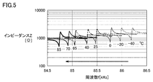
- FIG. 5 is a graph showing the relationship between the resonance frequency and the temperature of the piezoelectric device 40.
- the horizontal axis is the frequency [kHz] and the vertical axis is the impedance [ ⁇ ].
- the frequency of the portion where the impedance suddenly changes is the resonance frequency of the piezoelectric device 40, and the state of the change of the resonance frequency when the temperature is changed from ⁇ 40 ° C. to 85 ° C. is illustrated.
- the resonance frequency of the piezoelectric device 40 decreases as the temperature changes from ⁇ 40 ° C. to 85 ° C.
- the resonance frequency of the piezoelectric device 40 decreases as the amount of the adhered foreign matter increases. Then, only by measuring the change in the resonance frequency of the piezoelectric device 40 with the impedance detection unit 70, it is possible to accurately determine whether the fluctuation is due to foreign matter adhering to the surface of the protective cover 2 or due to a temperature change. I can't.
- the signal processing circuit 20 determines that foreign matter has adhered to the surface of the protective cover 2 only at the resonance frequency, and the temperature rises. There is a risk of erroneously recognizing that foreign matter has adhered to the surface of the protective cover 2.
- the signal processing circuit 20 when the signal processing circuit 20 erroneously recognizes that foreign matter has adhered to the surface of the protective cover 2 due to the temperature rise, the signal processing circuit 20 ACs the piezoelectric vibrator 15 in the direction of increasing the vibration amplitude of the piezoelectric device 40 in order to remove the foreign matter. The output signal will be applied. Increasing the vibration amplitude of the piezoelectric device 40 further raises the temperature of the surface of the protective cover 2, and the signal processing circuit 20 determines that the surface of the protective cover 2 becomes more unstable due to foreign matter adhering to the surface. Becomes difficult.
- the change in the resonance frequency of the piezoelectric device 40 is not limited to the temperature change, but the resonance frequency also changes due to the secular change of the joint portion between the protective cover 2 and the vibrating portion 12, the moisture absorption of the resin portion, and the like. Therefore, the signal processing circuit 20 needs to determine that foreign matter has adhered to the surface of the protective cover 2 together with information other than the change in the resonance frequency of the piezoelectric device 40.
- FIG. 6 is a graph in which the resonance frequency and the minimum impedance of the piezoelectric device 40 are plotted with respect to the temperature.
- FIG. 6A shows a change in the resonance frequency of the piezoelectric device 40 with respect to temperature, with the horizontal axis representing the temperature [° C.] and the vertical axis representing the resonance frequency [kHz].
- the resonance frequency of the piezoelectric device 40 decreases as the temperature increases.
- FIG. 6B shows a change in the minimum impedance (minimum impedance value) of the piezoelectric device 40 with respect to temperature, with the horizontal axis representing the temperature [° C.] and the vertical axis representing the minimum impedance [ ⁇ ].
- the minimum impedance of the piezoelectric device 40 decreases as the temperature increases.
- FIG. 7 is a graph in which the resonance frequency and the minimum impedance of the piezoelectric device 40 are plotted against the amount of foreign matter adhered.
- FIG. 7A shows a change in the resonance frequency of the piezoelectric device 40 with respect to the amount of water adhering to the surface of the protective cover 2.
- the horizontal axis is the amount of water adhering [ ⁇ l] and the vertical axis is the resonance frequency [. kHz].
- the resonance frequency of the piezoelectric device 40 decreases as the amount of water adhered increases.
- FIG. 7B shows the rate of change of the minimum impedance (minimum impedance value) of the piezoelectric device 40 with respect to the amount of water adhering to the surface of the protective cover 2, and the horizontal axis is the amount of water adhering [ ⁇ l].
- the vertical axis is the impedance change rate.
- the rate of change in the minimum impedance of the piezoelectric device 40 increases as the amount of water adhered increases.
- the rate of change of the current value I corresponding to the minimum impedance of the piezoelectric device 40 decreases as the amount of water adhered increases.
- the signal processing circuit 20 determines by combining the change in the resonance frequency of the piezoelectric device 40 and the change in the minimum impedance (minimum impedance value) of the piezoelectric device 40. , It is possible to accurately determine whether the fluctuation is due to foreign matter adhering to the surface of the protective cover 2 or the fluctuation due to a temperature change.
- the minimum impedance of the piezoelectric device 40 changes due to aging of the joint between the protective cover 2 and the vibrating portion 12, moisture absorption of the resin portion, etc., but it is different from the change when foreign matter adheres to the surface of the protective cover 2. Since they are different, it is possible to distinguish between the two.
- the resonance frequency and the current value are used instead of determining that the foreign matter has adhered to the surface of the protective cover 2 only by the resonance frequency.
- (Impedance) is used to determine that foreign matter has adhered to the surface of the protective cover 2. That is, the signal processing circuit 20 determines that foreign matter has adhered to the surface of the protective cover 2 based on the change in the resonance frequency and the current value at that time while the piezoelectric device 40 is operated in the search mode.
- the piezoelectric drive unit 30 sets the drive voltage Vdr to V1 and sweeps the frequency f to perform AC output in order to operate the piezoelectric device 40 in the search mode.
- a signal is applied to the piezoelectric vibrator 15.
- the impedance detection unit 70 measures the frequency at which the current of the piezoelectric drive unit 30 is maximized as the resonance frequency fr1 and the current value at that time as I1 among the sweeped frequencies f (step S103).
- the signal processing circuit 20 does not determine that foreign matter has adhered to the surface of the protective cover 2 only by the amount of change in resonance frequency (time change), but the amount of change in current value, which is a value related to impedance (time change). It is determined that foreign matter has adhered to the surface of the protective cover 2 due to time change).
- the signal processing circuit 20 When the difference value is larger than the predetermined threshold values fth and Is (NO in step S104), the signal processing circuit 20 returns the processing to step S102 and uses the resonance frequency fr1 and the current value I1 measured in step S104 as a reference.
- the memory is updated as the values f and I.
- the signal processing circuit 20 obtains the difference value between the reference values f and I and the resonance frequency fr1 and the current value I1 and obtains the difference value. Is compared with the predetermined threshold values fth1 and Is1 (step S105).
- the signal processing circuit 20 adheres to the surface of the protective cover 2. It is judged that the foreign matter that has been removed is large (the degree of dirt is severe).
- the signal processing circuit 20 determines the presence or absence of foreign matter adhering to the surface of the protective cover 2 by the threshold values fth and Is, and determines the degree of foreign matter adhering to the surface of the protective cover 2 by the threshold values fth1 and Is1.
- the signal processing circuit 20 determines that the foreign matter adhering to the surface of the protective cover 2 is small (the degree of dirt is light), and the piezoelectricity is reduced.
- the drive unit 30 sets the drive voltage Vdr to V2 (> V1) and applies an AC output signal having the drive frequency fdr as the resonance frequency fmax to the piezoelectric vibrator 15. (Step S106).
- the signal processing circuit 20 executes the drive mode A that drives only the piezoelectric drive unit 30 without driving the cleaning drive unit 60 (step S107).
- the signal processing circuit 20 determines that the foreign matter adhering to the surface of the protective cover 2 is large (the degree of dirtiness is severe).
- the piezoelectric drive unit 30 sets the drive voltage Vdr to V3 ( ⁇ V2) and transmits an AC output signal having the drive frequency fdr as the resonance frequency fmax to the piezoelectric vibrator 15. Apply (step S108). That is, the piezoelectric drive unit 30 vibrates the piezoelectric vibrator 15 with a weaker vibration than in the case of step S106.
- the signal processing circuit 20 drives the cleaning drive unit 60 to discharge the cleaning liquid, and executes the drive mode B that also drives the piezoelectric drive unit 30 (step S109). By executing the drive mode B, the signal processing circuit 20 can more strongly clean the foreign matter adhering to the protective cover 2.
- the signal processing circuit 20 discharges in the drive mode B based on at least one information of the resonance frequency, the value (current value) related to the impedance detected by the impedance detection unit 70, and the image captured by the image pickup unit 5. You may switch to a cleaning liquid having a stronger cleaning power than the cleaning liquid to be used.
- the signal processing circuit 20 determines whether or not the current value Idr measured by the impedance detection unit 70 has increased above a certain level (step S110).
- step S111 determines whether or not the operation for ending the cleaning process is accepted.
- the signal processing circuit 20 ends the cleaning process.
- the signal processing circuit 20 returns the process to step S101.
- the signal processing circuit 20 determines whether or not it has been driven for more than a certain time (for example, 1 minute) in the drive mode of the cleaning process. (Step S112).
- a certain time for example, 1 minute
- the piezoelectric device 40 is driven for a long time in the drive mode of the cleaning process, problems such as heat generation of the protective cover 2 may occur. Therefore, when the drive mode of the cleaning process is driven for more than a certain period of time (YES in step S112), the signal processing circuit 20 abnormally ends the cleaning process.
- the signal processing circuit 20 returns the process to step S105.
- FIG. 8 is a timing chart for explaining the operation of the cleaning device of the imaging unit.
- the upper row shows the waveform instructing the piezoelectric drive unit 30 to operate in the drive mode A (FIG. 4: step S107), and the lower row shows the operation of discharging the cleaning liquid to the cleaning liquid discharge unit 50.
- a waveform instructing the piezoelectric drive unit 30 to operate in the drive mode B (FIG. 4: step S109) is shown.
- the drive voltage Vdr is set to V1 and the frequency f is swept in order to determine whether or not foreign matter is attached to the surface of the protective cover 2, and the AC output signal is transmitted from the piezoelectric drive unit 30. It is applied to the piezoelectric vibrator 15.
- the signal processing circuit 20 determines the presence or absence of deposits on the protective cover 2 by comparing the measured changes in the resonance frequency fr and the current value I (difference values ⁇ fr and ⁇ I) with the threshold values fth and Is. Further, the signal processing circuit 20 is attached to the protective cover 2 in comparison with the measured changes in the resonance frequency fr and the current value I (difference values ⁇ fr, ⁇ I) and the threshold values fth1 ( ⁇ fs) and Is1 ( ⁇ Ith). Judge the degree of foreign matter.
- the signal processing circuit 20 sweeps the frequency f, scans a frequency in a certain range, sets the frequency at which the current is maximum as the resonance frequency fr, and measures the current at that time as the reciprocal of the impedance.
- the time change ( ⁇ fr) of the measured resonance frequency fr is negative
- the time change ( ⁇ I) of the current value I is negative
- the absolute value of ⁇ I is absolute.
- the time change ( ⁇ fr) of the measured resonance frequency fr is negative
- the time change ( ⁇ I) of the current value I is negative, ⁇ I.
- > 4 mA it is determined that the foreign matter adhering to the surface of the protective cover 2 is large (the degree of dirtiness is severe).
- the threshold value fth1 is 100 Hz
- the signal processing circuit 20 refers to the piezoelectric drive unit 30. Instructs the operation in the drive mode A.
- the piezoelectric drive unit 30 applies a voltage for vibrating the piezoelectric vibrator 15 with a vibration amplitude of a predetermined magnitude at a timing of time 0 s, as shown in the upper waveform shown in FIG.
- the piezoelectric drive unit 30 When the piezoelectric drive unit 30 is provided with a self-excited vibration circuit, the piezoelectric drive unit 30 can make the oscillation frequency follow the resonance frequency, so that the vibration amplitude is adjusted according to the current value Idr at the resonance frequency fr.
- the voltage applied to the piezoelectric vibrator 15 is changed. That is, in the piezoelectric drive unit 30, as the foreign matter adhering to the protective cover 2 becomes smaller due to the vibration of the piezoelectric vibrator 15 (for example, the timing of time 1.6 s and time 2.0 s), the current value Idr at the resonance frequency fr becomes smaller. This will increase, and the voltage applied so as to reduce the vibration amplitude of the piezoelectric vibrator 15 is reduced.
- the piezoelectric drive unit 30 assumes that the foreign matter adhering to the protective cover 2 is removed by the vibration of the piezoelectric vibrator 15 in the drive mode. Exits and shifts to search mode again.
- the signal processing circuit 20 is driven by the piezoelectric drive unit 30 and cleaning. Instruct unit 60 to operate in drive mode B.
- the cleaning drive unit 60 discharges the cleaning liquid from the cleaning liquid discharging unit 50 at the timing of time 0s (between time 0s and time 1.6s) as shown in the upper waveform shown in FIG.
- the piezoelectric drive unit 30 applies a voltage for vibrating the piezoelectric vibrator 15 with a vibration amplitude of a predetermined magnitude at a timing of time 2.0 s.
- the timing at which the piezoelectric drive unit 30 applies a voltage to vibrate the piezoelectric vibrator 15 is from any timing between time 0s and time 1.6s, even from the timing of time 0s. It may be.
- the piezoelectric drive unit 30 When the piezoelectric drive unit 30 is provided with a self-excited vibration circuit, the piezoelectric drive unit 30 can make the oscillation frequency follow the resonance frequency, so that the vibration amplitude is adjusted according to the current value Idr at the resonance frequency fr. The voltage applied to the piezoelectric vibrator 15 is changed. However, when the foreign matter adhering to the protective cover 2 does not change due to the vibration of the piezoelectric vibrator 15, the piezoelectric drive unit 30 stops applying the voltage to the piezoelectric vibrator 15 (for example, the timing of time 15s).
- the cleaning drive unit 60 discharges the cleaning liquid from the cleaning liquid discharging unit 50 again at the timing of the time 16s (between the time 16s and the time 17.6s).
- the piezoelectric drive unit 30 applies a voltage for vibrating the piezoelectric vibrator 15 with a vibration amplitude of a predetermined magnitude at a timing of time 18 s.
- the foreign matter adhering to the surface of the protective cover 2 is cleaned by using the vibration and the discharge of the cleaning liquid in combination.
- the cleaning device uses a cleaning liquid to wash away foreign substances, and then vibrates to atomize the remaining water droplets.
- the foreign matter adhering to the surface of the protective cover 2 is muddy water
- the water droplets are first atomized by vibration
- the solidified mud component remains and it becomes difficult to wash away the mud component with the cleaning liquid. Therefore, in the drive mode B, the mud component is less likely to remain by first washing the mud water with the cleaning liquid and then atomizing the remaining water droplets by vibration.
- the protective cover 2 by giving the protective cover 2 a vibration to the extent that the water does not atomize during the discharge of the cleaning liquid, the ultrasonic cleaning effect has the effect that the foreign matter stuck on the protective cover 2 is lifted and easily washed away. In this way, by combining the vibration and the discharge of the cleaning liquid, dirt can be effectively removed.
- FIG. 9 is a diagram showing the experimental results of the cleaning device for the imaging unit according to the first embodiment.
- the horizontal axis is time (s)
- the vertical axis on the left side is the current value I (A)
- the vertical axis on the right side is the resonance frequency fr (Hz).
- the cleaning device changes in electrical characteristics (for example, resonance frequency fr) due to temperature changes and aging, and electrical characteristics (for example, current value) due to foreign matter adhering to the surface of the protective cover 2. It is possible to distinguish the change of I) and prevent the malfunction. Further, in the cleaning device according to the present embodiment, effective cleaning can be performed while saving the cleaning liquid according to the degree of foreign matter adhering to the surface of the protective cover 2 by setting the threshold value. Further, in the cleaning device according to the present embodiment, the piezoelectric vibrator 15 is not vibrated when cleaning is not required, and the piezoelectric vibration is generated when the foreign matter adhering to the protective cover 2 is small (lightly soiled). By reducing the vibration amplitude of the child 15, the stress applied to the vibrating portion 12 can be reduced and the life can be improved.
- electrical characteristics for example, resonance frequency fr
- electrical characteristics for example, current value
- FIG. 10 is a schematic view showing the amplitude displacement when the protective cover 2 is vibrated in different vibration modes.
- FIG. 10A shows a view of the protective cover 2 when the imaging unit 100 shown in FIG. 2 is viewed from the left side in the drawing, and the protective cover 2 is vibrated in the first vibration mode (resonance frequency f1).
- the first vibration mode the portion having a large vibration displacement is the central portion (vibration antinode) of the protective cover 2, and the portion having a small vibration displacement is the vibrating portion 12 (vibration node) connected to the protective cover 2.
- the magnitude of the vibration displacement is represented by hatching, and the hatching in which the line spacing is narrow indicates that the vibration displacement is larger.
- FIG. 10B shows a view of the protective cover 2 when the imaging unit 100 shown in FIG. 2 is viewed from the left side in the drawing, and the protective cover 2 is vibrated in the second vibration mode (resonance frequency f2).
- the portion having a large vibration displacement is the vibrating portion 12 (vibration antinode) connected to the protective cover 2
- the portion having a small vibration displacement is the portion of the protective cover 2 (vibration node).
- FIG. 10C shows a view of the protective cover 2 when the imaging unit 100 shown in FIG. 2 is viewed from the left side in the drawing, and the protective cover 2 is vibrated in the third vibration mode (resonance frequency f3).
- the portion having a large vibration displacement is the peripheral edge portion (vibration antinode) of the protective cover 2
- the portion having a small vibration displacement is the portion other than the peripheral edge portion (vibration node).
- the vibrating portion 12 In the search mode, by vibrating the vibrating portion 12 in the second vibration mode in which the portion of the protective cover 2 becomes a vibration node, the influence of foreign matter adhering to the protective cover 2 is reduced, and the temperature and aging change. It is possible to measure fluctuations in electrical characteristics due to only. Therefore, the vibrating portion 12 is vibrated in the first vibration mode in which the portion of the protective cover 2 becomes the antinode of vibration, and the fluctuation of the electrical characteristics, which is greatly affected by the foreign matter adhering to the protective cover 2, is measured. By obtaining the difference from the measurement result in the second vibration mode, it is possible to measure the fluctuation of the electrical characteristics due only to the foreign matter adhering to the protective cover 2.
- the optimum vibration mode for atomization is the first vibration mode.
- the sensitivity to foreign matter is increased at the central portion of the protective cover 2 where the vibration displacement is maximized. In other parts, the sensitivity to foreign matter becomes small. Therefore, in the search mode, the vibrating portion 12 is vibrated in the first vibrating mode, the result of measuring the foreign matter adhering to the central portion of the protective cover 2 with high sensitivity, and the vibrating portion 12 is vibrated in the third vibrating mode. This may be performed in combination with the result of sensitively measuring the foreign matter adhering to the peripheral edge of the protective cover 2. This makes it possible to detect foreign matter adhering to any position of the protective cover 2, and further to identify which position of the protective cover 2 the foreign matter has adhered to. It is also possible to vibrate only at the position where foreign matter adheres to the protective cover 2.
- the cleaning device it is determined that foreign matter has adhered to the surface of the protective cover 2 by measuring two parameters (for example, resonance frequency fr and current value I).
- the information of the image captured by the imaging unit 5 may be used to determine the foreign matter adhering to the surface of the protective cover 2.
- the signal processing circuit 20 adds the amount of change in the resonance frequency fr (time change) and the amount of change in the current value I (time change) in order to determine that foreign matter has adhered to the surface of the protective cover 2. Information on the time change of the image captured by the imaging unit 5 may be taken into consideration.
- the signal processing circuit 20 combines the amount of change in the resonance frequency fr (time change) and the time change of the image captured by the imaging unit 5 in order to determine that foreign matter has adhered to the surface of the protective cover 2. May be good. Further, the signal processing circuit 20 combines the amount of change in the current value Ir (time change) and the time change of the image captured by the imaging unit 5 in order to determine that foreign matter has adhered to the surface of the protective cover 2. May be good.
- the signal processing circuit 20 when the amount of change in the resonance frequency fr is larger than the absolute value of the threshold value fth and the integrated brightness of the image captured by the imaging unit 5 decreases, foreign matter adheres to the surface of the protective cover 2. Judge that. As a result, the signal processing circuit 20 considers the amount of change in the resonance frequency fr, so that the decrease in the integrated brightness caused by the vehicle equipped with the imaging unit 100 entering the tunnel, for example, and the foreign matter on the surface of the protective cover 2 It is possible to distinguish from the decrease in the integrated brightness value caused by the adhesion of.
- the amount of change in the resonance frequency fr and the amount of change in the current value I are larger than the absolute values of the threshold values fth and It, respectively, and the integrated brightness of the image captured by the imaging unit 5 is greatly reduced.
- the signal processing circuit 20 determines that the foreign matter adhering to the surface of the protective cover 2 is a transparent object such as water. In this way, the signal processing circuit 20 more accurately determines the type of foreign matter adhering to the surface of the protective cover 2 by considering the information on the time change of the image captured by the imaging unit 5, and discharges the cleaning liquid. The presence or absence can be accurately determined.
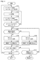
- FIG. 11 is a flowchart for explaining the operation of the cleaning device of the imaging unit according to the modified example of the first embodiment.
- the impedance detection unit 70 sets the frequency at which the current of the piezoelectric drive unit 30 is maximum (or the impedance which is the reciprocal of the current value is the minimum) among the swept frequencies f to the initial resonance frequency fr0, and the current at that time. The value is measured as I0 (step S101).
- the signal processing circuit 20 updates the memory with the initial resonance frequency fr0 and the current value I0 as the reference values f and I (step S102).
- the piezoelectric drive unit 30 sets the drive voltage Vdr to V1 and sweeps the frequency f to send the AC output signal to the piezoelectric vibrator 15 in order to operate the piezoelectric device 40 in the search mode. Apply to. Then, the impedance detection unit 70 measures the frequency at which the current of the piezoelectric drive unit 30 is maximized as the resonance frequency fr1 and the current value at that time as I1 among the sweeped frequencies f (step S103).
- the signal processing circuit 20 obtains a difference value between the reference values f and I updated in step S102 and the resonance frequency fr1 and the current value I1 and compares the difference value with the predetermined threshold values fth and Is (step S104). ..
- the signal processing circuit 20 When the difference value is larger than the predetermined threshold values fth and Is (NO in step S104), the signal processing circuit 20 returns the processing to step S102 and uses the resonance frequency fr1 and the current value I1 measured in step S104 as a reference.
- the memory is updated as the values f and I.
- the signal processing circuit 20 determines whether or not the brightness integral value (time change) of the image captured by the imaging unit 5 drops more than a certain level. Is determined (step S205).
- the signal processing circuit 20 uses the threshold values fth1 and Is1 having larger absolute values than the threshold values fth and Is, and does not determine the degree of foreign matter adhering to the surface of the protective cover 2, and the degree of foreign matter changes with time of the image. Can be judged.
- the signal processing circuit 20 determines that the foreign matter adhering to the surface of the protective cover 2 is a transparent material such as water, and is piezoelectrically driven.
- the unit 30 sets the drive voltage Vdr to V2 (> V1) and applies an AC output signal having the drive frequency fdr as the resonance frequency fmax to the piezoelectric vibrator 15 (Ste S106).
- the signal processing circuit 20 executes the drive mode A that drives only the piezoelectric drive unit 30 without driving the cleaning drive unit 60 (step S107).
- the signal processing circuit 20 determines that the foreign matter adhering to the surface of the protective cover 2 is an opaque substance such as mud, and is piezoelectrically driven.
- the unit 30 sets the drive voltage Vdr to V3 ( ⁇ V2) and applies an AC output signal having the drive frequency fdr as the resonance frequency fmax to the piezoelectric vibrator 15 (Ste S108).
- the signal processing circuit 20 drives the cleaning drive unit 60 to discharge the cleaning liquid, and executes the drive mode B that also drives the piezoelectric drive unit 30 (step S109).
- the signal processing circuit 20 determines whether or not the current value Idr measured by the impedance detection unit 70 has increased above a certain level (step S110). When the current value Idr increases to a certain level or more (YES in step S110), the signal processing circuit 20 determines whether or not the operation for ending the cleaning process is accepted (step S111). When the operation for ending the cleaning process is accepted (YES in step S111), the signal processing circuit 20 ends the cleaning process. On the other hand, when the operation for ending the cleaning process is not accepted (NO in step S111), the signal processing circuit 20 returns the process to step S101.
- the signal processing circuit 20 determines whether or not it has been driven for more than a certain time (for example, 30 minutes) in the drive mode of the cleaning process. (Step S112).
- a certain time for example, 30 minutes
- the piezoelectric device 40 is driven for a long time in the drive mode of the cleaning process, problems such as heat generation of the protective cover 2 may occur. Therefore, when the drive mode of the cleaning process is driven for more than a certain period of time (YES in step S112), the signal processing circuit 20 abnormally ends the cleaning process.
- the signal processing circuit 20 returns the process to step S105.
- the imaging unit 100 is provided with a cleaning device.
- This cleaning device includes a housing 1 that holds the imaging unit 5, a protective cover 2 that is arranged in the field of view of the imaging unit 5, a vibrating unit 12 that vibrates the protective cover 2, and a piezoelectric driving unit that drives the vibrating unit 12.
- the configuration includes 30, a signal processing circuit 20 that controls the piezoelectric drive unit 30, and an impedance detection unit 70 that detects a value (current value I) related to the impedance of the vibration unit 12 driven by the signal processing circuit 20.
- the signal processing circuit 20 changes the resonance frequency ( ⁇ f) when the vibrating unit 12 is driven by the first voltage (V1) and the change amount of the current value related to the impedance detected by the impedance detecting unit 70 ( ⁇ I). ) And the time change (brightness integrated value) of the image captured by the imaging unit 5, it is determined that foreign matter has adhered to the surface of the protective cover 2, and the vibrating unit is determined according to the determination. 12 is controlled to clean the surface of the protective cover 2.
- the cleaning device determines that foreign matter has adhered to the surface of the protective cover 2 based on at least two pieces of information, and controls the vibrating unit 12 according to the determination to control the protective cover 2. Since the surface of the surface is cleaned, highly efficient cleaning can be performed.
- the signal processing circuit 20 determines the drive frequency fdr for driving the vibrating unit 12 in order to clean the surface of the protective cover 2, and determines the drive frequency fdr and the drive frequency fdr.
- the vibrating unit 12 may be driven by the second voltage (V2).
- V2 the second voltage
- the piezoelectric drive unit 30 can clean the surface of the protective cover 2 with an appropriate drive frequency fdr and a second voltage (V2).
- the signal processing circuit 20 the amount of change in resonance frequency ( ⁇ f) when the vibrating unit 12 is driven by the first voltage (V1) is negative, and the time change of impedance detected by the impedance detecting unit 70 is positive (current value).
- the amount of change ( ⁇ I) is negative
- the signal processing circuit 20 can accurately determine whether the fluctuation is due to foreign matter adhering to the surface of the protective cover 2 or the fluctuation due to a temperature change.
- the signal processing circuit 20 the amount of change ( ⁇ f) in the resonance frequency when the vibrating unit 12 is driven by the first voltage (V1) is negative, and the time change (brightness) of the brightness obtained from the image captured by the imaging unit 5 is negative. If the integrated value) is negative, it may be determined that foreign matter has adhered to the surface of the protective cover 2. As a result, the signal processing circuit 20 can more accurately determine the type of foreign matter adhering to the surface of the protective cover 2 and accurately determine whether or not the cleaning liquid is discharged.
- the time change of impedance detected by the impedance detection unit 70 is positive (the amount of change in current value ( ⁇ I) is negative), and the time change of brightness (brightness integration) obtained from the image captured by the imaging unit 5 is positive. If the value) is negative, it may be determined that foreign matter has adhered to the surface of the protective cover 2. As a result, the signal processing circuit 20 can more accurately determine the type of foreign matter adhering to the surface of the protective cover 2 and accurately determine whether or not the cleaning liquid is discharged.
- the signal processing circuit 20 may specify the type of foreign matter adhering to the surface of the protective cover 2 based on the analysis result (brightness integrated value) of the image captured by the image sensor. As a result, the signal processing circuit 20 determines that the foreign matter adhering to the surface of the protective cover 2 is an opaque substance such as mud.
- the signal processing circuit 20 can drive the vibration unit 12 in a plurality of vibration modes, and drives the vibration unit 12 in order to determine that foreign matter has adhered to the surface of the protective cover 2 (for example, a first vibration mode).
- the first vibration mode + second vibration mode) and the vibration mode (for example, the first vibration mode) that drives the vibration unit 12 to clean the surface of the protective cover 2 may be different.
- the signal processing circuit 20 can measure fluctuations in electrical characteristics due only to foreign matter adhering to the protective cover 2.
- the signal processing circuit 20 may change the voltage (V2 or V3) for driving the vibrating unit 12 for cleaning the surface of the protective cover 2 based on at least one value of the resonance frequency and the impedance. As a result, the signal processing circuit 20 can change the vibration amplitude of the piezoelectric vibrator 15 according to the degree of foreign matter adhering to the protective cover 2.
- the cleaning liquid discharge unit 50 for discharging the cleaning liquid (cleaning body) is further provided on the surface of the protective cover 2, and the signal processing circuit 20 is provided from the cleaning liquid discharge unit 50 in response to the determination that foreign matter has adhered to the surface of the protective cover 2.
- the cleaning liquid may be discharged.
- the signal processing circuit 20 can more strongly clean the foreign matter adhering to the protective cover 2.
- the voltage for driving the vibrating unit 12 is equal to or higher than the first voltage (V1) and the second voltage (V2). ) It may be as follows. As a result, the signal processing circuit 20 can be cleaned by vibration in combination with cleaning by discharging the cleaning liquid. In the signal processing circuit 20, if cleaning is performed with the same vibration amplitude as cleaning with only vibration, the cleaning liquid is atomized and cannot be effectively used. Therefore, the vibrating unit 12 is driven by weak vibration.
- the cleaning liquid discharge unit 50 can discharge a first cleaning liquid for cleaning the surface of the protective cover 2 and a second cleaning liquid having a stronger cleaning power than the first cleaning liquid, and the signal processing circuit 20 can discharge the second cleaning liquid.
- the value (current value) related to the impedance detected by the impedance detecting unit 70, and the image captured by the imaging unit 5. The first cleaning liquid and the second cleaning liquid may be switched. As a result, the signal processing circuit 20 can more strongly clean the foreign matter adhering to the protective cover 2.
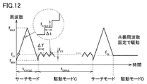
- FIG. 12 is a timing chart for explaining the control of the cleaning device of the imaging unit according to the second embodiment.
- the piezoelectric drive unit 30 sets the drive voltage Vdr to V1 and sweeps the frequency f from f MIN to f MAX to transmit the AC output signal to the piezoelectric vibrator. Apply to 15.
- the signal processing circuit 20 determines that the foreign matter adhering to the surface of the protective cover 2 is water based on the measurement results of the resonance frequency and the current value in the search mode, the signal processing circuit 20 sweeps around the resonance frequency f 01 .
- An AC output signal is applied to the piezoelectric vibrator 15.
- the signal processing circuit 20 can determine the presence / absence and degree of foreign matter adhering to the surface of the protective cover 2 with the configuration described in the first embodiment.
- the signal processing circuit 20 applies an AC output signal to the piezoelectric vibrator 15 by sweeping the range f FS before and after the resonance frequency f 01 in the period ⁇ T, as in the drive mode C shown in FIG.
- the cleaning device can prevent the temperature of the protective cover 2 from rising excessively by continuing the vibration at the resonance frequency f 01 , and atomizes the water (droplets) adhering to the surface of the protective cover 2. Can be made to.
- the cleaning device sweeps the AC output signal applied to the piezoelectric vibrator 15 in the range f FS before and after the resonance frequency f 01 , so that the water film adhering to the surface of the protective cover 2 vibrates in a steady state. It is possible to avoid the phenomenon that remains without atomization.
- the frequency of the AC output signal applied to the piezoelectric vibrator 15 changes in a stepped manner as shown in FIG. Specifically, the AC output signal increases or decreases by the frequency f STEP for each period ⁇ t.
- the signal processing circuit 20 drives the period ⁇ tDRIVE in the drive mode C and then drives it again in the search mode, and based on the measurement results of the resonance frequency and the current value in the search mode, the foreign matter adhering to the surface of the protective cover 2 Is judged to be mud.
- the surface tension differs depending on the liquid type, but also depends on the temperature of the liquid. Therefore, on the low temperature side where the surface tension is large, it is necessary to increase the vibration amplitude of the piezoelectric vibrator 15 to promote atomization. Further, the signal processing circuit 20 needs to change the vibration amplitude of the piezoelectric vibrator 15 according to the temperature in order to effectively atomize the foreign matter adhering to the surface of the protective cover 2.
- the cleaning device can adopt a cleaning method according to the mud and water as described above without relying on the discharge of the cleaning liquid.
- the signal processing circuit 20 has a duty value of t1 / (t1 + t2), where the time for strong vibration in the vicinity of the resonance frequency is time t1 and the time for vibration in the drive modes C and D is time t2. Can be controlled with. That is, the signal processing circuit 20 sets the time t2 longer than the time t1 to sweep the AC output signal in the range f FS before and after the resonance frequency f 01 as in the drive mode C. Can be applied to.
- the signal processing circuit 20 is capable of applying an AC output signal to the piezoelectric vibrator 15 and fixed at the resonance frequency f 02, such as drive mode D by setting longer than the time t1 and the time t2 ..
- the signal processing circuit 20 drives the vibrating unit 12 for cleaning the surface of the protective cover 2 in the vicinity of the resonance frequency for the first period (time).
- the duty ratio between the first period and the second period is determined based on at least one information of the (current value) and the image captured by the imaging unit 5.
- FIG. 13 is a block diagram for explaining the control of the cleaning device of the imaging unit 200 according to the third embodiment.
- the image pickup unit 200 includes an image pickup unit 5, a signal processing circuit 20, a piezoelectric drive unit 30, a piezoelectric device 40, a cleaning liquid discharge unit 50, a cleaning drive unit 60, an impedance detection unit 70, a power supply circuit 80, and a temperature measurement unit 90. There is.
- the imaging unit 200 has the same configuration except that the temperature measuring unit 90 is added to the imaging unit 100 shown in FIG. 3, and the same configuration is designated by the same reference numerals and detailed description thereof will not be repeated.
- the temperature measuring unit 90 can measure the temperature in the vicinity of the imaging unit 200, for example, the vibrating unit 12 and the protective cover 2.
- the temperature measuring unit 90 only needs to be able to output the measured temperature to the signal processing circuit 20, and a known temperature sensor and temperature measuring device can be used.
- the signal processing circuit 20 uses the temperature information measured by the temperature measuring unit 90 to change the drive voltage applied to the piezoelectric vibrator 15 in the drive mode in order to remove foreign matter adhering to the surface of the protective cover 2. ..
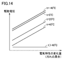
- FIG. 14 is a diagram for explaining the relationship between the amount of change in electrical characteristics and the drive voltage.
- the horizontal axis is the amount of change in electrical characteristics (for example, the amount of change in current value ( ⁇ I)), and the vertical axis is the drive voltage.
- the drive voltage applied to the piezoelectric vibrator 15 is substantially the same as long as the temperature is higher than 40 ° C. even if the amount of change in electrical characteristics changes.
- the amount of change in the electrical characteristics increases, the amount of foreign matter adhering to the surface of the protective cover 2 increases (the degree of dirt becomes worse).
- the drive voltage applied to the piezoelectric vibrator 15 becomes higher as the amount of change in electrical characteristics changes. That is, foreign matter (for example, droplets) adhering to the surface of the protective cover 2 increases the surface tension at a low temperature and becomes difficult to atomize and separate. Therefore, the signal processing circuit 20 is piezoelectric so as to compensate for this. The drive voltage applied to the vibrator 15 is increased. Further, when the vibration amplitude of the piezoelectric vibrator 15 has a temperature characteristic, the signal processing circuit 20 may be set to compensate the temperature characteristic of the vibration amplitude in addition to the compensation of the surface tension.
- the temperature measuring unit 90 is a temperature sensor and a temperature measuring device.
- the amount of change in the resonance frequency of the piezoelectric device 40 shown in FIG. 6A and the amount of change in the impedance of the piezoelectric device 40 shown in FIG. 6B can be obtained.
- the temperature may be estimated. That is, the temperature may be measured as the processing in the signal processing circuit 20 without providing the temperature measuring unit 90 in the imaging unit 200 shown in FIG.
- the temperature of the protective cover 2 is estimated based on the amount of change ( ⁇ I) of the current value with respect to the impedance detected by the unit 70, and the vibrating unit is used when cleaning the surface of the protective cover 2 based on the estimated temperature of the protective cover 2.
- the voltage for driving 12 is changed.
- the cleaning device in the cleaning device according to the third embodiment, it is possible to prevent the cleaning performance from deteriorating at low temperatures without separately providing a temperature measuring unit. Further, in the cleaning device, it is possible to prevent the joint portion from being stressed due to unnecessary vibration at a high temperature and shortening the life.
- the cleaning device according to the third embodiment further includes a temperature measuring unit 90 for measuring the temperature of the vibrating unit 12 or the protective cover 2, and the signal processing circuit 20 protects the signal processing circuit 20 based on the measurement result of the temperature measuring unit 90.
- the voltage for driving the vibrating portion 12 may be changed.
- the imaging unit according to the fourth embodiment has the same configuration as the imaging unit 100 shown in FIG. Since the signal processing circuit 20 has the same configuration except that it has a function of storing the impedance value and the resonance frequency detected by the impedance detection unit 70, the same configuration is designated by the same reference numerals and detailed description will be given. Do not repeat.
- FIG. 15 is a flowchart for explaining the operation of the cleaning device of the imaging unit according to the fourth embodiment.
- the signal processing circuit 20 operates the piezoelectric device 40 in the search mode, and determines that foreign matter has adhered to the surface of the protective cover 2.
- the piezoelectric drive unit 30 sets the drive voltage Vdr to V0, sweeps the frequency f, and applies an AC output signal to the piezoelectric vibrator 15. It is desirable that the drive voltage Vdr of the AC output signal applied to the piezoelectric vibrator 15 is reduced from the viewpoint of suppressing heat generation.
- the impedance detection unit 70 monitors the impedance of the piezoelectric drive unit 30 while operating the piezoelectric device 40 in the search mode. Specifically, the impedance detection unit 70 sets the frequency at which the current of the piezoelectric drive unit 30 becomes the maximum (or the impedance which is the reciprocal of the current value is the minimum) among the sweeped frequencies f at the initial resonance frequency fr1, at that time. Is measured as Z1 (step S301).
- the signal processing circuit 20 stores the measured initial resonance frequency fr1 and impedance Z1. Further, the impedance Z0, which is the reference value of the impedance, and the resonance frequency fr0, which is the reference value of the resonance frequency, are stored in advance in the signal processing circuit 20 from the beginning.
- FIG. 16 is a graph showing the relationship between the voltage of the piezoelectric device 40 and the rate of change of the resonance frequency.
- the horizontal axis represents the rate of change of the resonance frequency [%]
- the vertical axis represents the rate of change of the voltage [%].
- graph A shows that water-only foreign matter adheres to the surface of the protective cover 2
- graph B protects foreign matter in muddy water (50% muddy water) in which the weight ratio of mud contained in water is 50%.
- the graph C adheres to the surface of the cover 2
- the graph D is contained in the water.
- the slope between the rate of change in voltage and the rate of change in resonance frequency differs depending on the foreign matter adhering to the surface of the protective cover 2. Further, it has been experimentally found that when the protective cover 2 is vibrated several times to remove foreign matter, the inclination of graphs B to D approaches the inclination of graph A. That is, the slope between the voltage change rate and the resonance frequency change rate approaches the water slope from the muddy water slope by vibrating the protective cover 2 several times. Since voltage and impedance have a proportional relationship, the slope between the voltage change rate and the resonance frequency change rate is the slope between the impedance change rate (time change) and the resonance frequency change rate (time change). The tendency is similar.
- the foreign matter adhering to the surface of the protective cover 2 is determined by using the difference in inclination between the rate of change of impedance and the rate of change of resonance frequency. Specifically, in the cleaning device, the inclination between the past impedance change rate and the resonance frequency change rate is memorized, and by comparing with the inclination measured this time, even the type of foreign matter adhering to the surface of the protective cover 2 You can judge.
- the signal processing circuit 20 stores the impedance change rate ⁇ Z1 and the resonance frequency change rate ⁇ fr calculated in step S302.
- the signal processing circuit 20 determines the difference between the measured impedance Z1 and the reference value impedance Z0, and the measured resonance frequency fr1 and the reference value resonance frequency. Find the difference from fr0. The signal processing circuit 20 determines whether or not the obtained difference
- the signal processing circuit 20 determines that foreign matter has adhered to the surface of the protective cover 2.
- the signal processing circuit 20 ends the process.
- the signal processing circuit 20 has a foreign matter on the surface of the protective cover 2. It is determined that the foreign matter has adhered, and the process proceeds to determine the type of the adhered foreign matter.
- the signal processing circuit 20 repeats the search mode n times to determine the type of foreign matter adhering to the surface of the protective cover 2, and causes the impedance detection unit 70 to measure the impedance Zn and the resonance frequency frn (step).
- FIG. 17 is a graph showing changes in frequency and impedance when the search mode is repeatedly operated n times.
- the impedance detection unit 70 sets the frequency at which the current of the piezoelectric drive unit 30 becomes the maximum (or the impedance which is the reciprocal of the current value is the minimum) as the resonance frequency fr1, and the impedance at that time as Z1. Measure as.
- the measurement in step S301 may be the first measurement.
- the impedance detection unit 70 sets the frequency at which the current of the piezoelectric drive unit 30 is the maximum (or the impedance which is the reciprocal of the current value is the minimum) among the frequencies f swept n times, as the resonance frequency frn.
- the impedance at that time is measured as Zn.
- the signal processing circuit 20 obtains the slope between the measured impedance change rate and the resonance frequency change rate in order to determine the type of foreign matter adhering to the surface of the protective cover 2.
- the signal processing circuit 20 determines whether or not the obtained slope
- Graphs B and C to which foreign substances such as 100% muddy water and 100% of muddy water are attached change so that the slope approaches the slope of graph A when the search mode is repeated n times. That is, when the signal processing circuit 20 repeats the search mode n times and the inclination does not change much, it determines that the foreign matter adhering to the surface of the protective cover 2 is water, and repeats the search mode n times to change the inclination. If there is, it can be determined that the foreign matter adhering to the surface of the protective cover 2 is muddy water.
- the signal processing circuit 20 determines that the foreign matter adhering to the surface of the protective cover 2 is water.
- the drive frequency fdr is set to the resonance frequency, and the drive voltage Vdr is set to V1 (step S307).
- the signal processing circuit 20 executes the drive mode A that drives only the piezoelectric drive unit 30 based on the value set in step S307 without driving the cleaning drive unit 60 (step S308).
- the signal processing circuit 20 then returns the processing to step S303.
- the signal processing circuit 20 determines that the foreign matter adhering to the surface of the protective cover 2 is muddy water.
- the drive frequency fdr is set to the resonance frequency
- the drive voltage Vdr is set to V1
- the cleaning drive unit 60 is started (step S309).
- the signal processing circuit 20 discharges the cleaning liquid by the cleaning drive unit 60, and executes the drive mode B for driving the piezoelectric drive unit 30 based on the value set in step S309 (step S310).
- the signal processing circuit 20 then returns the processing to step S303.
- FIG. 18 is a diagram for explaining an example in the case of driving in the drive mode A.
- the signal processing circuit 20 determines in the search mode that the foreign matter adhering to the surface of the protective cover 2 is water, the signal processing circuit 20 does not drive the cleaning drive unit 60 in the drive mode A in the drive mode, but only the piezoelectric drive unit 30. Drive.
- the piezoelectric drive unit 30 is provided with a self-excited circuit, the piezoelectric drive unit 30 can make the oscillation frequency follow the resonance frequency.
- the signal processing circuit 20 is driven in the drive mode for a predetermined period of time, and then is driven again in the search mode to determine the presence or absence of foreign matter adhering to the surface of the protective cover 2.
- the signal processing circuit 20 ends the processing, and when it is determined that there is a foreign matter, the signal processing circuit 20 identifies the type of the foreign matter and shifts to the optimum drive mode. In this way, if the signal processing circuit 20 can determine that the foreign matter adhering to the surface of the protective cover 2 is water, the foreign matter water can be removed only by vibration, and the cleaning drive unit 60 such as a washer is wasted. You don't have to operate it.
- FIG. 19 is a diagram for explaining an example in the case of driving in the drive mode B.
- the signal processing circuit 20 determines in the search mode that the foreign matter adhering to the surface of the protective cover 2 is muddy water
- the signal processing circuit 20 drives the cleaning drive unit 60 and the piezoelectric drive unit 30 in the drive mode B in the drive mode.
- the cleaning drive unit 60 discharges the cleaning liquid to the protective cover 2 to wash away the dirt, and then the remaining water droplets are atomized by the piezoelectric drive unit 30.
- the signal processing circuit 20 discharges the cleaning liquid to the protective cover 2 by the cleaning drive unit 60 to wash away the dirt. Further, the signal processing circuit 20 is protected by the ultrasonic cleaning effect by applying vibration to the protective cover 2 to the extent that foreign matter is not atomized by the piezoelectric drive unit 30 during cleaning by the cleaning drive unit 60 with the cleaning liquid.
- the signal processing circuit 20 sets the threshold value th3 for the slope between the rate of change of impedance and the rate of change of resonance frequency to determine whether the foreign matter adhering to the surface of the protective cover 2 is water or muddy water.
- the threshold th3 should be set appropriately.
- the foreign matter adhering to the surface of the protective cover 2 can be determined by other than water or muddy water.
- the signal processing circuit 20 can determine whether the muddy water is 50% or 200% even if the muddy water is the same, by appropriately setting the threshold value th3. By determining the type of foreign matter adhering to the surface of the protective cover 2, the signal processing circuit 20 can select the optimum cleaning method and efficiently remove the foreign matter.
- the surface of the protective cover 2 is based on the inclination of the time change of the impedance and the time change of the resonance frequency detected by the signal processing circuit 20 by the impedance detection unit 70. Identify the type of foreign matter adhering to the.
- the signal processing circuit 20 can select the optimum cleaning method.
- the signal processing circuit 20 may store the change tendency of the gradient between the time change of the impedance detected by the impedance detection unit 70 and the time change of the resonance frequency according to the type of foreign matter adhering to the surface of the protective cover 2. ..
- the signal processing circuit 20 can determine the type of foreign matter other than water and muddy water.
- the cleaning device according to the fourth embodiment can be appropriately combined with the configurations described in the cleaning device according to the first embodiment.
- the vibration mode for driving the unit 12 may be different.
- the signal processing circuit 20 may change the voltage for driving the vibrating portion 12 for cleaning the surface of the protective cover 2 based on at least one value of the resonance frequency and the impedance.
- the signal processing circuit 20 discharges the cleaning liquid from the cleaning liquid discharge unit 50 to clean the surface of the protective cover 2, the voltage for driving the vibrating unit 12 is equal to or higher than the first voltage (V1) and the second voltage (V2). ) It may be as follows.
- the cleaning liquid discharge unit 50 can discharge a first cleaning liquid for cleaning the surface of the protective cover 2 and a second cleaning liquid having a stronger cleaning power than the first cleaning liquid, and is a signal processing circuit.
- Reference numeral 20 denotes at least one information of the resonance frequency when the vibrating unit 12 is driven by the first voltage, the value (current value) related to the impedance detected by the impedance detecting unit 70, and the image captured by the imaging unit 5.
- the first cleaning liquid and the second cleaning liquid may be switched based on the above.
- the cleaning device according to the fourth embodiment can be appropriately combined with the configuration described in the cleaning device according to the second embodiment.
- the signal processing circuit 20 drives the vibrating unit 12 for cleaning the surface of the protective cover 2 in the vicinity of the resonance frequency during the first period (time t1).
- the image captured by the imaging unit 5 the duty ratio between the first period and the second period may be determined.
- the cleaning device according to the fourth embodiment can be appropriately combined with the configuration described in the cleaning device according to the third embodiment.
- the change amount ( ⁇ f) of the resonance frequency when the signal processing circuit 20 drives the vibrating unit 12 with the first voltage (V1) and the impedance detecting unit 70 The temperature of the protective cover 2 is estimated based on the amount of change ( ⁇ I) of the current value with respect to the detected impedance, and the vibrating unit 12 is driven when cleaning the surface of the protective cover 2 based on the estimated temperature of the protective cover 2.
- the voltage may be changed.
- the cleaning device may further include a temperature measuring unit 90 for measuring the temperature of the vibrating unit 12 or the protective cover 2 described in the above-described third embodiment
- the signal processing circuit 20 may further include a temperature measuring unit 90.
- the voltage for driving the vibrating unit 12 may be changed when cleaning the surface of the protective cover 2 based on the measurement result of the temperature measuring unit 90.
- the configuration of the image pickup unit 5 is not described in detail, but the image pickup unit 5 may include a camera, LiDAR, Radar, and the like.
- the signal processing circuit 20 has at least one of a change in resonance frequency ( ⁇ f), a change in current value ( ⁇ I), and a time change in an image (integrated brightness). It was explained that it is determined that foreign matter has adhered to the surface of the protective cover 2 based on the two pieces of information. However, if the cleaning device further includes a temperature measuring unit 90, the signal processing circuit 20 has a change in resonance frequency ( ⁇ f), a change in current value ( ⁇ I), and a time change (brightness integration) of the image. It may be determined that foreign matter has adhered to the surface of the protective cover 2 based on the value) and at least two pieces of information of the temperature measured by the temperature measuring unit 90.
- a search mode for determining the presence / absence and degree of foreign matter adhering to the surface of the protective cover 2 and a search mode for removing the foreign matter adhering to the surface of the protective cover 2 It is driven separately from the drive mode.
- the cleaning device is not limited to this, and the cleaning device may be constantly driven in a search mode for determining the presence / absence and degree of foreign matter adhering to the surface of the protective cover 2, or may be intermittently driven at a predetermined cycle. Good.
- cleaning that vibrates the protective cover 2 and cleaning that discharges the cleaning liquid by the cleaning liquid discharge unit 50 are exemplified, but the present invention is not limited to this.
- foreign matter adhering to the surface of the protective cover 2 may be removed by cleaning in which air is discharged by the cleaning liquid discharge unit 50.
- the imaging unit according to the above-described embodiment has a configuration in which one cleaning nozzle 3 is provided in the housing 1 as shown in FIG. 1, but the present invention is not limited to this, and a plurality of cleaning nozzles 3 are provided.
- the configuration may be provided in the housing 1.
- the image pickup unit according to the above-described embodiment is not limited to the image pickup unit provided in the vehicle, and is similarly applied to the image pickup unit for which it is necessary to clean the translucent body arranged in the field of view of the image pickup element. can do.
- the image pickup unit As one of the information for determining that foreign matter has adhered to the surface of the protective cover 2, there is a time change of the image captured by the image pickup unit 5, and as an example, the image pickup unit 5 It was explained that it is a time change of the brightness integral value of the captured image.
- the present invention is not limited to this, and as a time change of the image captured by the imaging unit 5, for example, blurring of the edge of the captured image is evaluated by the frequency spectrum of image processing, and foreign matter is protected by the time change of the frequency spectrum of the protective cover 2. It may be determined that it has adhered to the surface.
- the signal processing circuit 20 can determine that raindrops have adhered to the surface of the protective cover 2 as foreign matter when the frequency at which the frequency power increases in the frequency spectrum changes to a low level.
- the signal processing circuit 20 can further improve the accuracy by combining the time change of the frequency spectrum and determining that the foreign matter has adhered to the surface of the protective cover 2.
Abstract
The present invention provides a cleaning device in which a signal processing circuit (20) determines that a foreign substance adheres on the surface of a protective cover (2) on the basis of at least two pieces of information among a change amount (Δf) of a resonant frequency when a vibration unit (12) is driven with a first voltage (V1), a change amount (ΔI) of a current value related to impedance detected by an impedance detection unit (70), and a temporal change (lightness integrated value) in an image captured by an imaging unit (5), and controls the vibration unit (12) in accordance with the determination to clean the surface of the protective cover (2).
Description
本発明は、洗浄装置、洗浄装置を備える撮像ユニット、および洗浄方法に関する。
The present invention relates to a cleaning device, an imaging unit including the cleaning device, and a cleaning method.
車両の前部や後部に撮像ユニットを設けて、当該撮像ユニットで撮像した画像を利用して安全装置を制御したり、自動運転制御を行ったりすることが行われている。このような撮像ユニットは、車外に設けられることが多いため、外部を覆う透光体(レンズや保護ガラス)に雨滴、泥、塵埃等の異物が付着することがある。透光体に異物が付着すると、当該撮像ユニットで撮像した画像に付着した異物が映り込み、鮮明な画像が得られなくなる。
Imaging units are provided at the front and rear of the vehicle, and the images captured by the imaging unit are used to control safety devices and to perform automatic driving control. Since such an imaging unit is often provided outside the vehicle, foreign matter such as raindrops, mud, and dust may adhere to the translucent body (lens or protective glass) that covers the outside. When foreign matter adheres to the translucent body, the foreign matter adhered to the image captured by the imaging unit is reflected, and a clear image cannot be obtained.
そこで、透光体の表面に付着した異物を判別し、透光体を振動させて異物を除去する洗浄装置が開発されている(特許文献1)。また、透光体の表面に洗浄液を吐出し、透光体を振動させて異物を除去する洗浄装置が開発されている(特許文献2)。
Therefore, a cleaning device has been developed that discriminates foreign matter adhering to the surface of the translucent body and vibrates the translucent body to remove the foreign matter (Patent Document 1). Further, a cleaning device has been developed in which a cleaning liquid is discharged onto the surface of a translucent body to vibrate the translucent body to remove foreign substances (Patent Document 2).
しかし、特許文献1に記載の洗浄装置は、透光体を振動することのみでは、泥水などを除去できない場合があった。例えば、透光体を振動することによって泥水中の水分が霧化してしまい、泥水中の泥の濃度が上昇して透光体を振動することのみでは、泥水などを除去できない場合があった。
However, the cleaning device described in Patent Document 1 may not be able to remove muddy water or the like only by vibrating the translucent body. For example, there are cases where the water in the muddy water is atomized by vibrating the translucent body, and the muddy water or the like cannot be removed only by vibrating the translucent body due to an increase in the concentration of mud in the muddy water.
また、特許文献2に記載の洗浄装置では、透光体の振動と洗浄液の吐出との組み合わせにより、透光体の異物を除去することができる。しかし、実走行において、撮像ユニットには、透光体の異物として雨滴のみがかかる状況が殆どであり、泥が付着することは稀である。そのため、特許文献2に記載の洗浄装置では、透光体の異物として水滴や微量の泥が付着した場合でも、洗浄液の吐出を行っているので、洗浄液の消費量が増大してしまい効率の低い洗浄となっていた。
Further, in the cleaning device described in Patent Document 2, foreign matter in the translucent body can be removed by combining the vibration of the translucent body and the discharge of the cleaning liquid. However, in actual driving, in most cases, only raindrops are applied to the image pickup unit as foreign matter of the translucent body, and mud rarely adheres to the image pickup unit. Therefore, in the cleaning device described in Patent Document 2, even when water droplets or a small amount of mud adhere as foreign matter to the translucent body, the cleaning liquid is discharged, so that the consumption of the cleaning liquid increases and the efficiency is low. It was a wash.
そこで、本発明の目的は、透光体に付着した異物に応じて、効率の高い洗浄を行うことができる洗浄装置、洗浄装置を備える撮像ユニット、および洗浄方法を提供する。
Therefore, an object of the present invention is to provide a cleaning device capable of performing highly efficient cleaning according to a foreign substance adhering to a translucent body, an imaging unit provided with the cleaning device, and a cleaning method.
本発明の一形態に係る洗浄装置は、撮像素子を保持する保持部と、撮像素子の視野に配置される透光体と、透光体を振動させる振動体と、振動体を駆動する駆動部と、駆動部を制御する制御部と、駆動部で駆動する振動体のインピーダンスに関する値を検出する検出部とを備え、制御部は、第1の電圧で振動体を駆動する場合の共振周波数の時間変化と、検出部で検出するインピーダンスに関する値の時間変化と、撮像素子で撮像した画像の時間変化とのうち少なくとも2つの情報に基づき、透光体の表面に異物が付着したことを判断し、当該判断に応じて振動体を制御して透光体の表面を洗浄する。
The cleaning device according to one embodiment of the present invention includes a holding unit that holds the image pickup element, a translucent body that is arranged in the field of view of the image pickup element, a vibrating body that vibrates the translucent body, and a driving unit that drives the vibrating body. A control unit that controls the drive unit and a detection unit that detects a value related to the impedance of the vibrating body driven by the driving unit are provided, and the control unit has a resonance frequency when the vibrating body is driven by the first voltage. Based on at least two pieces of information, the time change, the time change of the value related to the impedance detected by the detection unit, and the time change of the image captured by the imaging element, it is determined that foreign matter has adhered to the surface of the translucent body. , The surface of the translucent body is cleaned by controlling the vibrating body according to the judgment.
本発明の一形態に係る撮像ユニットは、上記に記載の洗浄装置を備える。
本発明の一形態に係る洗浄方法は、撮像素子を保持する保持部と、撮像素子の視野に配置される透光体と、透光体を振動させる振動体と、振動体を駆動する駆動部と、駆動部を制御する制御部と、駆動部で駆動する振動体のインピーダンスに関する値を検出する検出部とを備える洗浄装置で透光体の表面を洗浄する洗浄方法であって、サーチモードとして、第1の電圧で振動体を駆動するステップと、サーチモードにおける共振周波数の時間変化と、検出部で検出するインピーダンスに関する値の時間変化と、撮像素子で撮像した画像の時間変化とのうち少なくとも2つの情報に基づき、透光体の表面に異物が付着したことを判断するステップと、透光体の表面に異物が付着したことの判断に応じて振動体を駆動する駆動周波数を決定するステップと、ドライブモードとして、決定した駆動周波数および第2の電圧で振動体を駆動するステップとを含む。 The imaging unit according to one embodiment of the present invention includes the cleaning device described above.
The cleaning method according to one embodiment of the present invention includes a holding unit that holds the image pickup element, a translucent body that is arranged in the field of view of the image pickup element, a vibrating body that vibrates the translucent body, and a driving unit that drives the vibrating body. A cleaning method for cleaning the surface of the translucent body with a cleaning device including a control unit that controls the drive unit and a detection unit that detects a value related to the impedance of the vibrating body driven by the drive unit, as a search mode. , At least of the step of driving the vibrating body with the first voltage, the time change of the resonance frequency in the search mode, the time change of the value related to the impedance detected by the detection unit, and the time change of the image captured by the image pickup device. Based on the two pieces of information, a step of determining that foreign matter has adhered to the surface of the translucent body and a step of determining the drive frequency for driving the vibrating body according to the determination of foreign matter adhering to the surface of the translucent body. And, as the drive mode, the step of driving the vibrating body with the determined drive frequency and the second voltage is included.
本発明によれば、制御部が、少なくとも2つの情報に基づき、透光体の表面に異物が付着したことを判断し、透光体に付着した異物に応じて、効率の高い洗浄を行うことができる。
According to the present invention, the control unit determines that foreign matter has adhered to the surface of the translucent body based on at least two pieces of information, and performs highly efficient cleaning according to the foreign matter adhering to the translucent body. Can be done.
以下に、本実施の形態に係る撮像ユニットについて図面を参照して詳しく説明する。なお、図中同一符号は同一または相当部分を示す。
The imaging unit according to this embodiment will be described in detail below with reference to the drawings. In the figure, the same reference numerals indicate the same or corresponding parts.
(実施の形態1)
以下に、本実施の形態1に係る撮像ユニットについて図面を参照しながら説明する。図1は、本実施の形態1に係る撮像ユニット100の構成を説明するための斜視図である。図2は、本実施の形態1に係る撮像ユニット100の構成を説明するための断面図である。撮像ユニット100は、筐体1、筐体1の一面に設けられた透明の保護カバー2、保護カバー2に洗浄液(洗浄体)を吐出する開口部31を有する洗浄ノズル3、保護カバー2を振動させる振動体である振動部12、保護カバー2の内側に設けられた撮像部5を備えている。なお、撮像ユニット100から撮像部5を除いた、筐体1、保護カバー2、洗浄ノズル3および振動部12の構成が、撮像部5の撮像範囲に付着した異物(付着物)を洗浄する洗浄装置を構成している。 (Embodiment 1)
The imaging unit according to the first embodiment will be described below with reference to the drawings. FIG. 1 is a perspective view for explaining the configuration of theimaging unit 100 according to the first embodiment. FIG. 2 is a cross-sectional view for explaining the configuration of the imaging unit 100 according to the first embodiment. The imaging unit 100 vibrates the housing 1, the transparent protective cover 2 provided on one surface of the housing 1, the cleaning nozzle 3 having an opening 31 for discharging the cleaning liquid (cleaning body) into the protective cover 2, and the protective cover 2. It is provided with a vibrating unit 12 which is a vibrating body and an imaging unit 5 provided inside the protective cover 2. The configuration of the housing 1, the protective cover 2, the cleaning nozzle 3, and the vibrating unit 12 excluding the imaging unit 5 from the imaging unit 100 is a cleaning that cleans foreign matter (adhesion) adhering to the imaging range of the imaging unit 5. It constitutes a device.
以下に、本実施の形態1に係る撮像ユニットについて図面を参照しながら説明する。図1は、本実施の形態1に係る撮像ユニット100の構成を説明するための斜視図である。図2は、本実施の形態1に係る撮像ユニット100の構成を説明するための断面図である。撮像ユニット100は、筐体1、筐体1の一面に設けられた透明の保護カバー2、保護カバー2に洗浄液(洗浄体)を吐出する開口部31を有する洗浄ノズル3、保護カバー2を振動させる振動体である振動部12、保護カバー2の内側に設けられた撮像部5を備えている。なお、撮像ユニット100から撮像部5を除いた、筐体1、保護カバー2、洗浄ノズル3および振動部12の構成が、撮像部5の撮像範囲に付着した異物(付着物)を洗浄する洗浄装置を構成している。 (Embodiment 1)
The imaging unit according to the first embodiment will be described below with reference to the drawings. FIG. 1 is a perspective view for explaining the configuration of the
撮像部5は、図2に示すように筒状の本体部材4により支えられ、ベースプレート4aに固定されている。ベースプレート4aは、筐体1の一部に固定されている。そのため、筐体1は、本体部材4およびベースプレート4aを介して撮像部5を保持する保持部として機能している。なお、保持部は、撮像部5を保持することができれば図2に示した構造に限定されない。
As shown in FIG. 2, the imaging unit 5 is supported by the tubular main body member 4 and fixed to the base plate 4a. The base plate 4a is fixed to a part of the housing 1. Therefore, the housing 1 functions as a holding unit that holds the imaging unit 5 via the main body member 4 and the base plate 4a. The holding unit is not limited to the structure shown in FIG. 2 as long as the imaging unit 5 can be held.
撮像部5内には、撮像素子を含む回路6が内蔵されている。撮像部5の撮像方向に、レンズモジュール7が固定されている。レンズモジュール7は、筒状体からなり、内部に複数のレンズ9が設けられている。なお、撮像部5の構造は、レンズ9の前方に位置している被撮像物を撮像し得る限り特に限定されるものではない。
A circuit 6 including an image sensor is built in the image pickup unit 5. The lens module 7 is fixed in the imaging direction of the imaging unit 5. The lens module 7 is formed of a tubular body, and a plurality of lenses 9 are provided inside. The structure of the imaging unit 5 is not particularly limited as long as it can image an image to be imaged located in front of the lens 9.
筐体1は、角筒状で、たとえば金属や合成樹脂からなる。なお、筐体1は、円筒状などの他の形状であってもよい。筐体1の一端側にベースプレート4aが固定され、筐体1の他端側に保護カバー2および振動部12が設けられている。
The housing 1 has a square cylinder shape and is made of, for example, metal or synthetic resin. The housing 1 may have another shape such as a cylindrical shape. The base plate 4a is fixed to one end side of the housing 1, and the protective cover 2 and the vibrating portion 12 are provided on the other end side of the housing 1.
振動部12は、円筒状の形状を有している。振動部12は、円筒状の第1の筒部材13と、円筒状の第2の筒部材14と、円筒状の圧電振動子15とを有する。円筒状の圧電振動子15は、2枚の円筒状の圧電板16,17を有する。2枚の圧電板16,17は、厚み方向において、一方の圧電板の分極方向と他方の圧電板の分極方向とが逆方向となっている。
The vibrating portion 12 has a cylindrical shape. The vibrating unit 12 has a cylindrical first tubular member 13, a cylindrical second tubular member 14, and a cylindrical piezoelectric vibrator 15. The cylindrical piezoelectric vibrator 15 has two cylindrical piezoelectric plates 16 and 17. In the thickness directions of the two piezoelectric plates 16 and 17, the polarization direction of one piezoelectric plate and the polarization direction of the other piezoelectric plate are opposite to each other.
なお、本発明において、振動部や圧電振動子については、円筒状の他、角筒状であってもよい。好ましくは、円筒状すなわちリング状の形状が用いられる。
In the present invention, the vibrating portion and the piezoelectric vibrator may be cylindrical or square tubular. Preferably, a cylindrical or ring shape is used.
圧電板16,17は、チタン酸ジルコン酸鉛系圧電セラミックスからなる。もっとも、(K,Na)NbO3などの他の圧電セラミックスが用いられてもよい。さらにLiTaO3などの圧電単結晶が用いられてもよい。
The piezoelectric plates 16 and 17 are made of lead zirconate titanate-based piezoelectric ceramics. However, other piezoelectric ceramics such as (K, Na) NbO 3 may be used. Further, a piezoelectric single crystal such as LiTaO 3 may be used.
圧電板16,17の両面には、図示しない電極が形成されている。この電極は、たとえばAg/NiCu/NiCrの積層構造を有する。
Electrodes (not shown) are formed on both sides of the piezoelectric plates 16 and 17. This electrode has, for example, a laminated structure of Ag / NiCu / NiCr.
圧電振動子15の下面に、円筒状の第1の筒部材13が固定されている。第1の筒部材13は、金属からなる。金属としては、ジュラルミン、ステンレスまたはコバールなどを用いることができる。もっとも、第1の筒部材13は、導電性を有するSiなどの半導体からなるものであってもよい。
A cylindrical first tubular member 13 is fixed to the lower surface of the piezoelectric vibrator 15. The first tubular member 13 is made of metal. As the metal, duralumin, stainless steel, kovar and the like can be used. However, the first tubular member 13 may be made of a conductive semiconductor such as Si.
第1の筒部材13の一部と、第2の筒部材14の一部との間に圧電振動子15が挟持されている。第1の筒部材13及び第2の筒部材14は、いずれも金属からなり、導電性を有する。圧電板16,17のそれぞれの電極に交流電界を印加することにより、圧電振動子15を縦振動または横振動させることができる。第2の筒部材14の一部においては、内周面に雌ネジ部が形成されている。それによって、第2の筒部材14に、第1の筒部材13がねじ込まれ、第1の筒部材13が第2の筒部材14に固定されている。このねじ込みより、圧電振動子15の上面及び下面に、第1の筒部材13の一部および第2の筒部材14の一部が圧接されている。
The piezoelectric vibrator 15 is sandwiched between a part of the first tubular member 13 and a part of the second tubular member 14. The first tubular member 13 and the second tubular member 14 are both made of metal and have conductivity. By applying an AC electric field to each of the electrodes of the piezoelectric plates 16 and 17, the piezoelectric vibrator 15 can be vibrated vertically or horizontally. In a part of the second tubular member 14, a female screw portion is formed on the inner peripheral surface. As a result, the first tubular member 13 is screwed into the second tubular member 14, and the first tubular member 13 is fixed to the second tubular member 14. By this screwing, a part of the first tubular member 13 and a part of the second tubular member 14 are pressure-welded to the upper surface and the lower surface of the piezoelectric vibrator 15.
従って、圧電振動子15において生じた振動により、振動部12全体が効率良く振動する。本実施の形態では、振動部12が縦効果または横効果により効率よく励振される。
Therefore, the vibration generated in the piezoelectric vibrator 15 causes the entire vibrating portion 12 to vibrate efficiently. In the present embodiment, the vibrating portion 12 is efficiently excited by the vertical effect or the horizontal effect.
他方、第2の筒部材14には、外側に張り出したフランジ部14bが設けられている。フランジ部14bが、筐体1の凹部に載置され、かつ固定されている。
On the other hand, the second tubular member 14 is provided with a flange portion 14b overhanging to the outside. The flange portion 14b is placed and fixed in the recess of the housing 1.
第2の筒部材14の端には、外側に張り出したフランジ部14cが設けられている。このフランジ部14bとフランジ部14cとの間に連なる部分が、薄肉部14aである。薄肉部14aの厚みは、第1の筒部材13の厚みよりも薄くなっている。そのため、筒状の薄肉部14aは、振動部12の振動により大きく変位する。この薄肉部14aの存在により、振動、特に振幅の拡大を図ることができる。
A flange portion 14c overhanging outward is provided at the end of the second tubular member 14. The portion connected between the flange portion 14b and the flange portion 14c is the thin-walled portion 14a. The thickness of the thin portion 14a is thinner than the thickness of the first tubular member 13. Therefore, the tubular thin-walled portion 14a is largely displaced by the vibration of the vibrating portion 12. Due to the presence of the thin portion 14a, vibration, particularly amplitude can be expanded.
フランジ部14cに、保護カバー2が固定されている。保護カバー2は、被撮像物からの光を透光する透光体として機能している。保護カバー2は、一方向に開いた開口を有する。この開口の端が、フランジ部14cに接合されている。この接合は、たとえば、接着剤やろう材を用いて接合されている。また、熱圧着や陽極接合などを用いてもよい。
The protective cover 2 is fixed to the flange portion 14c. The protective cover 2 functions as a translucent body that transmits light from the object to be imaged. The protective cover 2 has an opening that opens in one direction. The end of this opening is joined to the flange portion 14c. This bonding is performed using, for example, an adhesive or a brazing material. Further, thermocompression bonding or anode bonding may be used.
保護カバー2は、フランジ部14cに接合した端から延びるドーム状の形状を有している。本実施の形態では、このドーム状の形状が半球の形状とされている。なお、撮像部5は、たとえば170°の視野角を備える。もっとも、ドーム状の形状は半球状の形状に限定されるものではない。半球に、円筒を連ねた形状や、半球よりも小さい曲面形状などを有していてもよい。保護カバー2は、その全体が透光性を有している。本実施の形態では、保護カバー2がガラスからなる。もっとも、ガラスに限らず、透明なプラスチックスなどにより構成されていてもよい。あるいは、透光性のセラミックスにより構成されていてもよい。もっとも、用途によっては、強化ガラスを用いることが好ましい。それによって、強度を高めることができる。さらに、ガラスの場合には、表面に、強度を高めるために、DLCなどからなるコーティング層が形成されていてもよい。
The protective cover 2 has a dome shape extending from the end joined to the flange portion 14c. In the present embodiment, this dome-shaped shape is a hemispherical shape. The imaging unit 5 has, for example, a viewing angle of 170 °. However, the dome shape is not limited to the hemispherical shape. The hemisphere may have a shape in which cylinders are connected, a curved surface shape smaller than the hemisphere, and the like. The protective cover 2 has a translucent property as a whole. In the present embodiment, the protective cover 2 is made of glass. However, the material is not limited to glass, and may be made of transparent plastic or the like. Alternatively, it may be made of translucent ceramics. However, it is preferable to use tempered glass depending on the application. Thereby, the strength can be increased. Further, in the case of glass, a coating layer made of DLC or the like may be formed on the surface in order to increase the strength.
保護カバー2内に、前述したレンズモジュール7および撮像部5が配置されている。この保護カバー2を通して外部の被撮像物の撮影が行われる。
The lens module 7 and the imaging unit 5 described above are arranged in the protective cover 2. An image of an external object to be imaged is taken through the protective cover 2.
筐体1には、保護カバー2に洗浄液を吐出する開口部31を有する洗浄ノズル3が設けられている。洗浄ノズル3は、筒状形状で開口部31を設けた反対側の端部から洗浄液が供給され、開口部31から保護カバー2の端に洗浄液を吐出する。洗浄ノズル3の先端は、撮像部5の撮像範囲(視野)の外部にあり、開口部31は、撮像部5の画像に写り込む位置にはない。図2では、洗浄液の流れが矢印で示されている。この洗浄ノズル3は、洗浄液を吐出する吐出部として機能している。本実施の形態では、筐体1に洗浄ノズル3を1本設けた構成を示しているが、筐体1に洗浄ノズル3を複数本設けた構成であってもよい。
The housing 1 is provided with a cleaning nozzle 3 having an opening 31 for discharging the cleaning liquid in the protective cover 2. The cleaning nozzle 3 has a tubular shape, and the cleaning liquid is supplied from the opposite end provided with the opening 31, and the cleaning liquid is discharged from the opening 31 to the end of the protective cover 2. The tip of the cleaning nozzle 3 is outside the imaging range (field of view) of the imaging unit 5, and the opening 31 is not at a position where the image is reflected in the image of the imaging unit 5. In FIG. 2, the flow of the cleaning liquid is indicated by an arrow. The cleaning nozzle 3 functions as a discharge unit for discharging the cleaning liquid. In the present embodiment, the housing 1 is provided with one cleaning nozzle 3, but the housing 1 may be provided with a plurality of cleaning nozzles 3.
なお、本実施の形態では、撮像ユニット100に設けた洗浄装置(以下、単に洗浄装置と称す)が洗浄ノズル3を備え、保護カバー2に洗浄液を吐出して洗浄することが可能な構成として説明するが、洗浄ノズル3を備えず保護カバー2を振動させることのみで洗浄を行う構成であってもよい。もちろん、洗浄装置は、洗浄ノズル3に加えて、または洗浄ノズル3に代えて別の構成(たとえば、エアブロワなど)を備えてもよい。
In the present embodiment, the cleaning device provided in the image pickup unit 100 (hereinafter, simply referred to as a cleaning device) is provided with a cleaning nozzle 3, and the cleaning liquid can be discharged to the protective cover 2 for cleaning. However, the cleaning nozzle 3 may not be provided and cleaning may be performed only by vibrating the protective cover 2. Of course, the cleaning device may include another configuration (for example, an air blower, etc.) in addition to or in place of the cleaning nozzle 3.
次に、洗浄装置の制御について図を用いて説明する。図3は、本実施の形態1に係る撮像ユニット100の洗浄装置の制御を説明するためのブロック図である。
Next, the control of the cleaning device will be described with reference to the figure. FIG. 3 is a block diagram for explaining control of the cleaning device of the imaging unit 100 according to the first embodiment.
撮像ユニット100は、撮像部5、信号処理回路20、圧電駆動部30、圧電デバイス40、洗浄液吐出部50、洗浄駆動部60、インピーダンス検出部70、および電源回路80を含んでいる。信号処理回路20は、撮像部5からの撮像信号を処理するとともに、圧電駆動部30および洗浄駆動部60に対して制御信号を供給する制御部である。洗浄液吐出部50は、洗浄ノズル3の開口部31から洗浄液を吐出する構成を1つのブロックとして図示してある。
The image pickup unit 100 includes an image pickup unit 5, a signal processing circuit 20, a piezoelectric drive unit 30, a piezoelectric device 40, a cleaning liquid discharge unit 50, a cleaning drive unit 60, an impedance detection unit 70, and a power supply circuit 80. The signal processing circuit 20 is a control unit that processes the image pickup signal from the image pickup unit 5 and supplies the control signal to the piezoelectric drive unit 30 and the cleaning drive unit 60. The cleaning liquid discharge unit 50 is shown as one block in which the cleaning liquid is discharged from the opening 31 of the cleaning nozzle 3.
信号処理回路20は、制御中枢としてのCPU(Central Processing Unit)、CPUが動作するためのプログラムや制御データ等を記憶しているROM(Read Only Memory)、CPUのワークエリアとして機能するRAM(Random Access Memory)、周辺機器との信号の整合性を保つための入出力インターフェイス等を設けてある。
The signal processing circuit 20 includes a CPU (Central Processing Unit) as a control center, a ROM (Read Only Memory) that stores programs and control data for operating the CPU, and a RAM (Random) that functions as a work area of the CPU. Access Memory), input / output interfaces for maintaining signal consistency with peripheral devices, etc. are provided.
圧電駆動部30は、信号処理回路20からの制御信号と駆動電圧に応じた、周波数f、電圧Vの交流出力信号を生成する。圧電デバイス40は、図2に示す圧電振動子15を有する振動部12により構成され、圧電振動子15に交流出力信号を印加することで、振動部12および保護カバー2を振動させて異物を除去する。
The piezoelectric drive unit 30 generates an AC output signal having a frequency f and a voltage V according to the control signal from the signal processing circuit 20 and the drive voltage. The piezoelectric device 40 is composed of a vibrating portion 12 having a piezoelectric vibrator 15 shown in FIG. 2, and by applying an AC output signal to the piezoelectric vibrator 15, the vibrating portion 12 and the protective cover 2 are vibrated to remove foreign matter. To do.
また、信号処理回路20は、洗浄液を保護カバー2に吐出して洗浄する制御信号を生成することができる。洗浄駆動部60は、信号処理回路20からの制御信号に基づいて洗浄液吐出部50より洗浄液を保護カバー2に吐出させる制御を行う。
Further, the signal processing circuit 20 can generate a control signal for cleaning by discharging the cleaning liquid to the protective cover 2. The cleaning drive unit 60 controls to discharge the cleaning liquid from the cleaning liquid discharge unit 50 to the protective cover 2 based on the control signal from the signal processing circuit 20.
インピーダンス検出部70は、圧電振動子15に交流出力信号を印加して圧電デバイス40を動作させている場合に、圧電駆動部30の電流をモニタしている。
The impedance detection unit 70 monitors the current of the piezoelectric drive unit 30 when the piezoelectric device 40 is operated by applying an AC output signal to the piezoelectric vibrator 15.
次に、撮像ユニットの洗浄装置の動作についてフローチャートに基づいて説明する。図4は、本実施の形態1に係る撮像ユニットの洗浄装置の動作を説明するためのフローチャートである。まず、信号処理回路20は、圧電デバイス40をサーチモードで動作させて、保護カバー2の表面に異物が付着したことを判断する。圧電駆動部30は、圧電デバイス40をサーチモードで動作するために、駆動電圧VdrをV1とし、周波数fをスイープさせて交流出力信号を圧電振動子15に印加する。なお、圧電振動子15に印加する交流出力信号は、発熱抑制の観点から駆動電圧Vdrを小さくする方が望ましい。
Next, the operation of the cleaning device of the imaging unit will be described based on the flowchart. FIG. 4 is a flowchart for explaining the operation of the cleaning device of the imaging unit according to the first embodiment. First, the signal processing circuit 20 operates the piezoelectric device 40 in the search mode, and determines that foreign matter has adhered to the surface of the protective cover 2. In order to operate the piezoelectric device 40 in the search mode, the piezoelectric drive unit 30 sets the drive voltage Vdr to V1, sweeps the frequency f, and applies an AC output signal to the piezoelectric vibrator 15. It is desirable that the drive voltage Vdr of the AC output signal applied to the piezoelectric vibrator 15 is reduced from the viewpoint of suppressing heat generation.
インピーダンス検出部70は、サーチモードで圧電デバイス40を動作させている間、圧電駆動部30の電流をモニタしている。具体的に、インピーダンス検出部70は、スイープさせた周波数fのうち、圧電駆動部30の電流が最大(または電流値の逆数であるインピーダンスが最小)となる周波数を初期の共振周波数fr0、そのときの電流値をI0として測定している(ステップS101)。信号処理回路20は、測定した初期の共振周波数fr0、および電流値I0を、基準値f、Iとして記憶を更新する(ステップS102)。
The impedance detection unit 70 monitors the current of the piezoelectric drive unit 30 while operating the piezoelectric device 40 in the search mode. Specifically, the impedance detection unit 70 sets the frequency at which the current of the piezoelectric drive unit 30 becomes the maximum (or the impedance which is the reciprocal of the current value is the minimum) among the sweeped frequencies f at the initial resonance frequency fr0, at that time. The current value of is measured as I0 (step S101). The signal processing circuit 20 updates the memory of the measured initial resonance frequency fr0 and current value I0 as reference values f and I (step S102).
ここで、圧電デバイス40の共振周波数と温度との関係を説明する。図5は、圧電デバイス40の共振周波数と温度との関係を示すグラフである。図5では、横軸を周波数[kHz]、縦軸をインピーダンス[Ω]としている。図5に示すグラフでは、インピーダンスが急激に変化している箇所の周波数が圧電デバイス40の共振周波数であり、温度が-40℃から85℃まで変化させた場合の共振周波数の変化の様子が図示されている。当該グラフから分かるように、温度が-40℃から85℃に変化するに従って、圧電デバイス40の共振周波数は低下している。
Here, the relationship between the resonance frequency of the piezoelectric device 40 and the temperature will be described. FIG. 5 is a graph showing the relationship between the resonance frequency and the temperature of the piezoelectric device 40. In FIG. 5, the horizontal axis is the frequency [kHz] and the vertical axis is the impedance [Ω]. In the graph shown in FIG. 5, the frequency of the portion where the impedance suddenly changes is the resonance frequency of the piezoelectric device 40, and the state of the change of the resonance frequency when the temperature is changed from −40 ° C. to 85 ° C. is illustrated. Has been done. As can be seen from the graph, the resonance frequency of the piezoelectric device 40 decreases as the temperature changes from −40 ° C. to 85 ° C.
一方、保護カバー2の表面に異物が付着した場合、圧電デバイス40の共振周波数は、付着している異物の量が多くなるに従い低下する。そうすると、インピーダンス検出部70で、圧電デバイス40の共振周波数の変化を測定するのみでは、保護カバー2の表面に異物が付着したことによる変動なのか、温度変化による変動なのかを正確に判断することができない。特に、圧電デバイス40の共振周波数は、温度上昇によって低下することが明らかとなったため、信号処理回路20は、共振周波数のみで保護カバー2の表面に異物が付着したことを判断すると、温度上昇により保護カバー2の表面に異物が付着したと誤認識する虞がある。
On the other hand, when foreign matter adheres to the surface of the protective cover 2, the resonance frequency of the piezoelectric device 40 decreases as the amount of the adhered foreign matter increases. Then, only by measuring the change in the resonance frequency of the piezoelectric device 40 with the impedance detection unit 70, it is possible to accurately determine whether the fluctuation is due to foreign matter adhering to the surface of the protective cover 2 or due to a temperature change. I can't. In particular, since it has become clear that the resonance frequency of the piezoelectric device 40 decreases as the temperature rises, the signal processing circuit 20 determines that foreign matter has adhered to the surface of the protective cover 2 only at the resonance frequency, and the temperature rises. There is a risk of erroneously recognizing that foreign matter has adhered to the surface of the protective cover 2.
さらに、信号処理回路20は、温度上昇により保護カバー2の表面に異物が付着したと誤認識した場合、異物を除去するために圧電デバイス40の振動振幅を上昇させる方向で圧電振動子15に交流出力信号を印加することになる。圧電デバイス40の振動振幅を上昇させると保護カバー2の表面の温度をさらに上昇させることになり、信号処理回路20は、保護カバー2の表面に異物が付着したことでさらに不安定となり判断することが難しくなる。
Further, when the signal processing circuit 20 erroneously recognizes that foreign matter has adhered to the surface of the protective cover 2 due to the temperature rise, the signal processing circuit 20 ACs the piezoelectric vibrator 15 in the direction of increasing the vibration amplitude of the piezoelectric device 40 in order to remove the foreign matter. The output signal will be applied. Increasing the vibration amplitude of the piezoelectric device 40 further raises the temperature of the surface of the protective cover 2, and the signal processing circuit 20 determines that the surface of the protective cover 2 becomes more unstable due to foreign matter adhering to the surface. Becomes difficult.
圧電デバイス40の共振周波数の変化は、温度変化に限定されず、保護カバー2と振動部12との接合部の経年変化、樹脂部の吸湿などによっても共振周波数に変化が生じる。そのため、信号処理回路20は、圧電デバイス40の共振周波数の変化以外の情報とあわせて、保護カバー2の表面に異物が付着したことを判断する必要がある。
The change in the resonance frequency of the piezoelectric device 40 is not limited to the temperature change, but the resonance frequency also changes due to the secular change of the joint portion between the protective cover 2 and the vibrating portion 12, the moisture absorption of the resin portion, and the like. Therefore, the signal processing circuit 20 needs to determine that foreign matter has adhered to the surface of the protective cover 2 together with information other than the change in the resonance frequency of the piezoelectric device 40.
ここで、図5に示すグラフから分かるように、温度が-40℃から85℃に変化するに従って、圧電デバイス40の共振周波数が低下するとともに、インピーダンスの最小値も低下している。当該関係を分かり易く説明するため、温度に対する圧電デバイス40の共振周波数の変化のグラフと、温度に対するインピーダンスの最小値の変化のグラフとに分けて説明する。図6は、温度に対して圧電デバイス40の共振周波数、インピーダンスの最小値をそれぞれプロットしたグラフである。
Here, as can be seen from the graph shown in FIG. 5, as the temperature changes from −40 ° C. to 85 ° C., the resonance frequency of the piezoelectric device 40 decreases, and the minimum value of impedance also decreases. In order to explain the relationship in an easy-to-understand manner, a graph of a change in the resonance frequency of the piezoelectric device 40 with respect to temperature and a graph of a change in the minimum value of impedance with respect to temperature will be described separately. FIG. 6 is a graph in which the resonance frequency and the minimum impedance of the piezoelectric device 40 are plotted with respect to the temperature.
図6(a)には、温度に対する圧電デバイス40の共振周波数の変化が示されており、横軸が温度[℃]、縦軸が共振周波数[kHz]である。図6(a)に示すグラフから分かるように、圧電デバイス40の共振周波数は、温度が高くなるに従い低下している。図6(b)には、温度に対する圧電デバイス40の最小インピーダンス(インピーダンスの最小値)の変化が示されており、横軸が温度[℃]、縦軸が最小インピーダンス[Ω]である。図6(b)に示すグラフから分かるように、圧電デバイス40の最小インピーダンスは、温度が高くなるに従い低下する。
FIG. 6A shows a change in the resonance frequency of the piezoelectric device 40 with respect to temperature, with the horizontal axis representing the temperature [° C.] and the vertical axis representing the resonance frequency [kHz]. As can be seen from the graph shown in FIG. 6A, the resonance frequency of the piezoelectric device 40 decreases as the temperature increases. FIG. 6B shows a change in the minimum impedance (minimum impedance value) of the piezoelectric device 40 with respect to temperature, with the horizontal axis representing the temperature [° C.] and the vertical axis representing the minimum impedance [Ω]. As can be seen from the graph shown in FIG. 6B, the minimum impedance of the piezoelectric device 40 decreases as the temperature increases.
一方、保護カバー2の表面に異物が付着した場合の圧電デバイス40の共振周波数、インピーダンスの最小値の変化について説明する。図7は、異物の付着量に対して圧電デバイス40の共振周波数、インピーダンスの最小値をそれぞれプロットしたグラフである。
On the other hand, changes in the resonance frequency and the minimum impedance of the piezoelectric device 40 when foreign matter adheres to the surface of the protective cover 2 will be described. FIG. 7 is a graph in which the resonance frequency and the minimum impedance of the piezoelectric device 40 are plotted against the amount of foreign matter adhered.
図7(a)には、保護カバー2の表面に付着した水の量に対する圧電デバイス40の共振周波数の変化が示されており、横軸が水付着量[μl]、縦軸が共振周波数[kHz]である。図7(a)に示すグラフから分かるように、圧電デバイス40の共振周波数は、水付着量が多くなるに従い低下している。図7(b)には、保護カバー2の表面に付着した水の量に対する圧電デバイス40の最小インピーダンス(インピーダンスの最小値)の変化率が示されており、横軸が水付着量[μl]、縦軸がインピーダンス変化率である。図7(b)に示すグラフから分かるように、圧電デバイス40の最小インピーダンスの変化率は、水付着量が多くなるに従い高くなる。なお、圧電デバイス40の最小インピーダンスに対応する電流値Iの変化率は、逆に水付着量が多くなるに従い低くなる。
FIG. 7A shows a change in the resonance frequency of the piezoelectric device 40 with respect to the amount of water adhering to the surface of the protective cover 2. The horizontal axis is the amount of water adhering [μl] and the vertical axis is the resonance frequency [. kHz]. As can be seen from the graph shown in FIG. 7A, the resonance frequency of the piezoelectric device 40 decreases as the amount of water adhered increases. FIG. 7B shows the rate of change of the minimum impedance (minimum impedance value) of the piezoelectric device 40 with respect to the amount of water adhering to the surface of the protective cover 2, and the horizontal axis is the amount of water adhering [μl]. , The vertical axis is the impedance change rate. As can be seen from the graph shown in FIG. 7B, the rate of change in the minimum impedance of the piezoelectric device 40 increases as the amount of water adhered increases. On the contrary, the rate of change of the current value I corresponding to the minimum impedance of the piezoelectric device 40 decreases as the amount of water adhered increases.
図6および図7のグラフから分かるように、信号処理回路20は、圧電デバイス40の共振周波数の変化と、圧電デバイス40の最小インピーダンス(インピーダンスの最小値)の変化とを組み合わせて判断することで、保護カバー2の表面に異物が付着したことによる変動なのか、温度変化による変動なのかを正確に判断することができる。なお、保護カバー2と振動部12との接合部の経年変化、樹脂部の吸湿などによっても圧電デバイス40の最小インピーダンスに変化が生じるが、保護カバー2の表面に異物が付着した場合の変化と異なるため、両者を区別して判断することが可能である。
As can be seen from the graphs of FIGS. 6 and 7, the signal processing circuit 20 determines by combining the change in the resonance frequency of the piezoelectric device 40 and the change in the minimum impedance (minimum impedance value) of the piezoelectric device 40. , It is possible to accurately determine whether the fluctuation is due to foreign matter adhering to the surface of the protective cover 2 or the fluctuation due to a temperature change. The minimum impedance of the piezoelectric device 40 changes due to aging of the joint between the protective cover 2 and the vibrating portion 12, moisture absorption of the resin portion, etc., but it is different from the change when foreign matter adheres to the surface of the protective cover 2. Since they are different, it is possible to distinguish between the two.
そこで、本実施の形態1に係る信号処理回路20では、共振周波数のみで保護カバー2の表面に異物が付着したことを判断するのではなく、共振周波数および電流値(または電流値の逆数であるインピーダンス)で保護カバー2の表面に異物が付着したことを判断する。つまり、信号処理回路20は、圧電デバイス40をサーチモードで動作させている間の共振周波数、そのときの電流値の変化で保護カバー2の表面に異物が付着したことを判断する。
Therefore, in the signal processing circuit 20 according to the first embodiment, the resonance frequency and the current value (or the reciprocal of the current value) are used instead of determining that the foreign matter has adhered to the surface of the protective cover 2 only by the resonance frequency. (Impedance) is used to determine that foreign matter has adhered to the surface of the protective cover 2. That is, the signal processing circuit 20 determines that foreign matter has adhered to the surface of the protective cover 2 based on the change in the resonance frequency and the current value at that time while the piezoelectric device 40 is operated in the search mode.
図4に戻って、一定時間後(たとえば、1秒後)、圧電駆動部30は、圧電デバイス40をサーチモードで動作するために、駆動電圧VdrをV1とし、周波数fをスイープさせて交流出力信号を圧電振動子15に印加する。そして、インピーダンス検出部70は、スイープさせた周波数fのうち、圧電駆動部30の電流が最大となる周波数を共振周波数fr1、そのときの電流値をI1として測定する(ステップS103)。
Returning to FIG. 4, after a certain period of time (for example, after 1 second), the piezoelectric drive unit 30 sets the drive voltage Vdr to V1 and sweeps the frequency f to perform AC output in order to operate the piezoelectric device 40 in the search mode. A signal is applied to the piezoelectric vibrator 15. Then, the impedance detection unit 70 measures the frequency at which the current of the piezoelectric drive unit 30 is maximized as the resonance frequency fr1 and the current value at that time as I1 among the sweeped frequencies f (step S103).
信号処理回路20は、ステップS102で更新した基準値f、Iと共振周波数fr1、電流値I1との差分値を求め、当該差分値が予め定めてある閾値fth、Ithと比較する(ステップS104)。具体的には、信号処理回路20は、Δfr(=fr1-fr)≦-fth、およびΔI(=I1-I)≦-Ithの関係を満たしているか否かを判断する。つまり、信号処理回路20は、共振周波数が減少する変化量(Δfr)が閾値fth以下で、かつ電流値が減少する変化量(ΔI)が閾値Ith以下である場合、保護カバー2の表面に異物が付着したと判断する。
The signal processing circuit 20 obtains a difference value between the reference values f and I updated in step S102 and the resonance frequency fr1 and the current value I1 and compares the difference value with the predetermined threshold values fth and Is (step S104). .. Specifically, the signal processing circuit 20 determines whether or not the relationship of Δfr (= fr1-fr) ≦ −fs and ΔI (= I1-I) ≦ −Ith is satisfied. That is, in the signal processing circuit 20, when the amount of change (Δfr) at which the resonance frequency decreases is less than or equal to the threshold value fth and the amount of change (ΔI) at which the current value decreases is less than or equal to the threshold value Is, foreign matter is present on the surface of the protective cover 2. Is judged to have adhered.
前述したように、信号処理回路20は、共振周波数の変化量(時間変化)のみで保護カバー2の表面に異物が付着したと判断するのではなく、インピーダンスに関する値である電流値の変化量(時間変化)で保護カバー2の表面に異物が付着したことを判断している。
As described above, the signal processing circuit 20 does not determine that foreign matter has adhered to the surface of the protective cover 2 only by the amount of change in resonance frequency (time change), but the amount of change in current value, which is a value related to impedance (time change). It is determined that foreign matter has adhered to the surface of the protective cover 2 due to time change).
差分値が予め定めてある閾値fth、Ithより大きい場合(ステップS104でNO)、信号処理回路20は、処理をステップS102に戻し、ステップS104で測定した共振周波数fr1、および電流値I1を、基準値f、Iとして記憶を更新する。
When the difference value is larger than the predetermined threshold values fth and Is (NO in step S104), the signal processing circuit 20 returns the processing to step S102 and uses the resonance frequency fr1 and the current value I1 measured in step S104 as a reference. The memory is updated as the values f and I.
差分値が予め定めてある閾値fth、Ith以下の場合(ステップS104でYES)、信号処理回路20は、基準値f、Iと共振周波数fr1、電流値I1との差分値を求め、当該差分値が予め定めてある閾値fth1、Ith1と比較する(ステップS105)。なお、閾値fth1、Ith1は、ステップS104で用いた閾値fth、Ithより絶対値が大きい(fth1>fth、Ith1>Ith)。具体的には、信号処理回路20は、Δfr(=fr1-fr)≦-fth1、およびΔI(=I1-I)≦-Ith1の関係を満たしているか否かを判断する。つまり、信号処理回路20は、共振周波数が減少する変化量(Δfr)が閾値fth1以下で、かつ電流値が減少する変化量(ΔI)が閾値Ith1以下である場合、保護カバー2の表面に付着した異物が大きい(汚れ具合がひどい)と判断する。
When the difference value is equal to or less than the predetermined threshold value fth and Is (YES in step S104), the signal processing circuit 20 obtains the difference value between the reference values f and I and the resonance frequency fr1 and the current value I1 and obtains the difference value. Is compared with the predetermined threshold values fth1 and Is1 (step S105). The threshold values fth1 and Is1 have larger absolute values than the threshold values fth and Is used in step S104 (fs1> fth, Is1> Is). Specifically, the signal processing circuit 20 determines whether or not the relationship of Δfr (= fr1-fr) ≦ −fs1 and ΔI (= I1-I) ≦ −Ith1 is satisfied. That is, when the change amount (Δfr) at which the resonance frequency decreases is the threshold value fth1 or less and the change amount (ΔI) at which the current value decreases is the threshold value Is1 or less, the signal processing circuit 20 adheres to the surface of the protective cover 2. It is judged that the foreign matter that has been removed is large (the degree of dirt is severe).
信号処理回路20は、閾値fth、Ithにより保護カバー2の表面に付着した異物の有無を判断し、閾値fth1、Ith1により保護カバー2の表面に付着した異物の程度を判断している。
The signal processing circuit 20 determines the presence or absence of foreign matter adhering to the surface of the protective cover 2 by the threshold values fth and Is, and determines the degree of foreign matter adhering to the surface of the protective cover 2 by the threshold values fth1 and Is1.
差分値が予め定めてある閾値fth1、Ith1より大きい場合(ステップS105でNO)、信号処理回路20は、保護カバー2の表面に付着した異物が小さい(汚れ具合が軽い)と判断して、圧電駆動部30は、圧電デバイス40を駆動モードで動作するために、駆動電圧VdrをV2(>V1)に設定し、駆動周波数fdrを共振周波数fmaxとする交流出力信号を圧電振動子15に印加する(ステップS106)。信号処理回路20は、洗浄駆動部60を駆動せずに、圧電駆動部30のみを駆動する駆動モードAを実行する(ステップS107)。
When the difference value is larger than the predetermined thresholds fth1 and Is1 (NO in step S105), the signal processing circuit 20 determines that the foreign matter adhering to the surface of the protective cover 2 is small (the degree of dirt is light), and the piezoelectricity is reduced. In order to operate the piezoelectric device 40 in the drive mode, the drive unit 30 sets the drive voltage Vdr to V2 (> V1) and applies an AC output signal having the drive frequency fdr as the resonance frequency fmax to the piezoelectric vibrator 15. (Step S106). The signal processing circuit 20 executes the drive mode A that drives only the piezoelectric drive unit 30 without driving the cleaning drive unit 60 (step S107).
一方、差分値が予め定めてある閾値fth1、Ith1以下の場合(ステップS105でYES)、信号処理回路20は、保護カバー2の表面に付着した異物が大きい(汚れ具合がひどい)と判断して、圧電駆動部30は、圧電デバイス40を駆動モードで動作するために、駆動電圧VdrをV3(<V2)に設定し、駆動周波数fdrを共振周波数fmaxとする交流出力信号を圧電振動子15に印加する(ステップS108)。つまり、圧電駆動部30は、ステップS106の場合より弱振動で圧電振動子15を振動させる。信号処理回路20は、洗浄駆動部60を駆動させて洗浄液を吐出させて、圧電駆動部30も駆動する駆動モードBを実行する(ステップS109)。信号処理回路20は、駆動モードBを実行することで、保護カバー2に付着した異物をより強力に洗浄できる。なお、信号処理回路20は、共振周波数と、インピーダンス検出部70で検出するインピーダンスに関する値(電流値)と、撮像部5で撮像した画像とのうち少なくとも1つの情報に基づき、駆動モードBで吐出する洗浄液よりも強力な洗浄力を有する洗浄液とを切り替えてもよい。
On the other hand, when the difference values are equal to or less than the predetermined thresholds fth1 and Is1 (YES in step S105), the signal processing circuit 20 determines that the foreign matter adhering to the surface of the protective cover 2 is large (the degree of dirtiness is severe). In order to operate the piezoelectric device 40 in the drive mode, the piezoelectric drive unit 30 sets the drive voltage Vdr to V3 (<V2) and transmits an AC output signal having the drive frequency fdr as the resonance frequency fmax to the piezoelectric vibrator 15. Apply (step S108). That is, the piezoelectric drive unit 30 vibrates the piezoelectric vibrator 15 with a weaker vibration than in the case of step S106. The signal processing circuit 20 drives the cleaning drive unit 60 to discharge the cleaning liquid, and executes the drive mode B that also drives the piezoelectric drive unit 30 (step S109). By executing the drive mode B, the signal processing circuit 20 can more strongly clean the foreign matter adhering to the protective cover 2. The signal processing circuit 20 discharges in the drive mode B based on at least one information of the resonance frequency, the value (current value) related to the impedance detected by the impedance detection unit 70, and the image captured by the image pickup unit 5. You may switch to a cleaning liquid having a stronger cleaning power than the cleaning liquid to be used.
ステップS108またはステップS109の洗浄により保護カバー2の表面に付着した異物が除去されると、インピーダンス検出部70で測定される電流値Idrが一定以上に増加する。つまり、インピーダンス検出部70で測定される電流値Idrは、保護カバー2の表面に異物が付着していないときの電流値Idrの値にほぼ戻る。そのため、信号処理回路20は、インピーダンス検出部70で測定される電流値Idrが一定以上に増加したか否かを判断する(ステップS110)。
When the foreign matter adhering to the surface of the protective cover 2 is removed by cleaning in step S108 or step S109, the current value Idr measured by the impedance detection unit 70 increases above a certain level. That is, the current value Idr measured by the impedance detection unit 70 substantially returns to the value of the current value Idr when no foreign matter adheres to the surface of the protective cover 2. Therefore, the signal processing circuit 20 determines whether or not the current value Idr measured by the impedance detection unit 70 has increased above a certain level (step S110).
電流値Idrが一定以上に増加した場合(ステップS110でYES)、信号処理回路20は、洗浄処理を終了する操作を受付けているか否か判断する(ステップS111)。洗浄処理を終了する操作を受付けている場合(ステップS111でYES)、信号処理回路20は、洗浄処理を終了する。一方、洗浄処理を終了する操作を受付けていない場合(ステップS111でNO)、信号処理回路20は、処理をステップS101に戻す。
When the current value Idr increases above a certain level (YES in step S110), the signal processing circuit 20 determines whether or not the operation for ending the cleaning process is accepted (step S111). When the operation for ending the cleaning process is accepted (YES in step S111), the signal processing circuit 20 ends the cleaning process. On the other hand, when the operation for ending the cleaning process is not accepted (NO in step S111), the signal processing circuit 20 returns the process to step S101.
電流値Idrが一定以上に増加していない場合(ステップS110でNO)、信号処理回路20は、洗浄処理の駆動モードで一定時間(たとえば、1分間)を超えて駆動しているか否かを判断する(ステップS112)。洗浄処理の駆動モードで長時間、圧電デバイス40を駆動した場合、保護カバー2が発熱するなどの不具合が発生する可能性がある。そこで、洗浄処理の駆動モードで一定時間を超えて駆動している場合(ステップS112でYES)、信号処理回路20は、洗浄処理を異常終了する。洗浄処理の駆動モードにおいて一定時間以下で駆動している場合(ステップS112でNO)、信号処理回路20は、処理をステップS105に戻す。
When the current value Idr has not increased more than a certain amount (NO in step S110), the signal processing circuit 20 determines whether or not it has been driven for more than a certain time (for example, 1 minute) in the drive mode of the cleaning process. (Step S112). When the piezoelectric device 40 is driven for a long time in the drive mode of the cleaning process, problems such as heat generation of the protective cover 2 may occur. Therefore, when the drive mode of the cleaning process is driven for more than a certain period of time (YES in step S112), the signal processing circuit 20 abnormally ends the cleaning process. When the cleaning process is driven in the drive mode for a certain period of time or less (NO in step S112), the signal processing circuit 20 returns the process to step S105.
次に、撮像ユニット100の洗浄装置の動作についてタイミングチャートを用いてさらに詳しく説明する。図8は、撮像ユニットの洗浄装置の動作を説明するためのタイミングチャートである。図8に示すタイミングチャートでは、上段が圧電駆動部30に対して駆動モードA(図4:ステップS107)での動作を指示する波形、下段が洗浄液吐出部50に対して洗浄液を吐出する動作を伴い圧電駆動部30に対して駆動モードB(図4:ステップS109)での動作を指示する波形が図示されている。
Next, the operation of the cleaning device of the imaging unit 100 will be described in more detail using a timing chart. FIG. 8 is a timing chart for explaining the operation of the cleaning device of the imaging unit. In the timing chart shown in FIG. 8, the upper row shows the waveform instructing the piezoelectric drive unit 30 to operate in the drive mode A (FIG. 4: step S107), and the lower row shows the operation of discharging the cleaning liquid to the cleaning liquid discharge unit 50. A waveform instructing the piezoelectric drive unit 30 to operate in the drive mode B (FIG. 4: step S109) is shown.
まず、信号処理回路20は、サーチモードにおいて、保護カバー2の表面に異物が付着しているか判断するために駆動電圧VdrをV1とし、周波数fをスイープさせて交流出力信号を圧電駆動部30から圧電振動子15に印加させる。
First, in the signal processing circuit 20, in the search mode, the drive voltage Vdr is set to V1 and the frequency f is swept in order to determine whether or not foreign matter is attached to the surface of the protective cover 2, and the AC output signal is transmitted from the piezoelectric drive unit 30. It is applied to the piezoelectric vibrator 15.
信号処理回路20は、測定した共振周波数fr、電流値Iのそれぞれの変化(差分値Δfr、ΔI)と閾値fth、Ithと比較して保護カバー2の付着物の有無を判断する。さらに、信号処理回路20は、測定した共振周波数fr、電流値Iのそれぞれの変化(差分値Δfr、ΔI)と閾値fth1(<fth)、Ith1(<Ith)と比較して保護カバー2に付着した異物の程度を判断する。
The signal processing circuit 20 determines the presence or absence of deposits on the protective cover 2 by comparing the measured changes in the resonance frequency fr and the current value I (difference values Δfr and ΔI) with the threshold values fth and Is. Further, the signal processing circuit 20 is attached to the protective cover 2 in comparison with the measured changes in the resonance frequency fr and the current value I (difference values Δfr, ΔI) and the threshold values fth1 (<fs) and Is1 (<Ith). Judge the degree of foreign matter.
具体的に、信号処理回路20は、周波数fをスイープさせて一定範囲の周波数をスキャンし、そのうちで電流が最大となる周波数を共振周波数frとし、そのときの電流をインピーダンスの逆数として測定する。信号処理回路20は、測定した共振周波数frの時間変化(Δfr)が負で、Δfrの絶対値(|Δfr|)>50Hz、かつ電流値Iの時間変化(ΔI)が負で、ΔIの絶対値|ΔI|>2mAのとき、保護カバー2の表面に異物が付着していると判断する。なお、閾値fthは50Hz、閾値Ithは2mAとする。
Specifically, the signal processing circuit 20 sweeps the frequency f, scans a frequency in a certain range, sets the frequency at which the current is maximum as the resonance frequency fr, and measures the current at that time as the reciprocal of the impedance. In the signal processing circuit 20, the time change (Δfr) of the measured resonance frequency fr is negative, the absolute value of Δfr (| Δfr |)> 50 Hz, and the time change (ΔI) of the current value I is negative, and the absolute value of ΔI is absolute. When the value | ΔI |> 2 mA, it is determined that foreign matter is attached to the surface of the protective cover 2. The threshold value fth is 50 Hz, and the threshold value Is is 2 mA.
さらに、信号処理回路20は、測定した共振周波数frの時間変化(Δfr)が負で、Δfrの絶対値(|Δfr|)>100Hz、かつ電流値Iの時間変化(ΔI)が負で、ΔIの絶対値|ΔI|>4mAのとき、保護カバー2の表面に付着した異物が大きい(汚れ具合がひどい)と判断する。なお、閾値fth1は100Hz、閾値Ith1は4mAとする。
Further, in the signal processing circuit 20, the time change (Δfr) of the measured resonance frequency fr is negative, the absolute value of Δfr (| Δfr |)> 100 Hz, and the time change (ΔI) of the current value I is negative, ΔI. When the absolute value of | ΔI |> 4 mA, it is determined that the foreign matter adhering to the surface of the protective cover 2 is large (the degree of dirtiness is severe). The threshold value fth1 is 100 Hz, and the threshold value Is1 is 4 mA.
サーチモードにおいて、保護カバー2の表面に異物が付着していると判断し、保護カバー2に付着した異物が小さい(汚れ具合が軽い)場合、信号処理回路20は、圧電駆動部30に対して駆動モードAでの動作を指示する。圧電駆動部30は、図8に示す上段の波形のように、時間0sのタイミングで所定の大きさの振動振幅で圧電振動子15を振動させるための電圧を印加する。
In the search mode, when it is determined that foreign matter is attached to the surface of the protective cover 2 and the foreign matter attached to the protective cover 2 is small (the degree of dirt is light), the signal processing circuit 20 refers to the piezoelectric drive unit 30. Instructs the operation in the drive mode A. The piezoelectric drive unit 30 applies a voltage for vibrating the piezoelectric vibrator 15 with a vibration amplitude of a predetermined magnitude at a timing of time 0 s, as shown in the upper waveform shown in FIG.
圧電駆動部30に自励振回路を設けた場合、圧電駆動部30は、発振周波数を共振周波数に追随させることができるので、共振周波数frにおける電流値Idrに応じて、振動振幅を調整するように圧電振動子15に印加する電圧を変化させている。つまり、圧電駆動部30は、圧電振動子15の振動により保護カバー2に付着した異物が小さくなるにつれて(たとえば、時間1.6s、時間2.0sのタイミング)、共振周波数frにおける電流値Idrが増加することになり、圧電振動子15の振動振幅を小さくするように印加する電圧を低下させている。
When the piezoelectric drive unit 30 is provided with a self-excited vibration circuit, the piezoelectric drive unit 30 can make the oscillation frequency follow the resonance frequency, so that the vibration amplitude is adjusted according to the current value Idr at the resonance frequency fr. The voltage applied to the piezoelectric vibrator 15 is changed. That is, in the piezoelectric drive unit 30, as the foreign matter adhering to the protective cover 2 becomes smaller due to the vibration of the piezoelectric vibrator 15 (for example, the timing of time 1.6 s and time 2.0 s), the current value Idr at the resonance frequency fr becomes smaller. This will increase, and the voltage applied so as to reduce the vibration amplitude of the piezoelectric vibrator 15 is reduced.
圧電駆動部30は、共振周波数frにおける電流値Idrが一定以上増加した場合(たとえば、時間10sのタイミング)、保護カバー2に付着した異物が圧電振動子15の振動により除去されたとして、駆動モードが終了して再びサーチモードに移行する。
When the current value Idr at the resonance frequency fr increases by a certain amount or more (for example, at the timing of time 10 s), the piezoelectric drive unit 30 assumes that the foreign matter adhering to the protective cover 2 is removed by the vibration of the piezoelectric vibrator 15 in the drive mode. Exits and shifts to search mode again.
サーチモードにおいて、保護カバー2の表面に異物が付着していると判断し、保護カバー2に付着した異物が大きい(汚れ具合がひどい)場合、信号処理回路20は、圧電駆動部30および洗浄駆動部60に対して駆動モードBでの動作を指示する。洗浄駆動部60は、図8に示す上段の波形のように、時間0sのタイミングで洗浄液吐出部50から洗浄液を吐出させる(時間0s~時間1.6sの間)。その後、圧電駆動部30は、時間2.0sのタイミングで所定の大きさの振動振幅で圧電振動子15を振動させるための電圧を印加する。なお、圧電駆動部30が圧電振動子15を振動させるために電圧を印加するタイミングは、時間0sのタイミングからであっても、時間0s~時間1.6sの間のうちの何れかのタイミングからであってもよい。
In the search mode, if it is determined that foreign matter is attached to the surface of the protective cover 2 and the foreign matter attached to the protective cover 2 is large (severely dirty), the signal processing circuit 20 is driven by the piezoelectric drive unit 30 and cleaning. Instruct unit 60 to operate in drive mode B. The cleaning drive unit 60 discharges the cleaning liquid from the cleaning liquid discharging unit 50 at the timing of time 0s (between time 0s and time 1.6s) as shown in the upper waveform shown in FIG. After that, the piezoelectric drive unit 30 applies a voltage for vibrating the piezoelectric vibrator 15 with a vibration amplitude of a predetermined magnitude at a timing of time 2.0 s. The timing at which the piezoelectric drive unit 30 applies a voltage to vibrate the piezoelectric vibrator 15 is from any timing between time 0s and time 1.6s, even from the timing of time 0s. It may be.
圧電駆動部30に自励振回路を設けた場合、圧電駆動部30は、発振周波数を共振周波数に追随させることができるので、共振周波数frにおける電流値Idrに応じて、振動振幅を調整するように圧電振動子15に印加する電圧を変化させている。しかし、圧電駆動部30は、圧電振動子15の振動により保護カバー2に付着した異物が変化しない場合、圧電振動子15への電圧の印加を停止する(たとえば、時間15sのタイミング)。
When the piezoelectric drive unit 30 is provided with a self-excited vibration circuit, the piezoelectric drive unit 30 can make the oscillation frequency follow the resonance frequency, so that the vibration amplitude is adjusted according to the current value Idr at the resonance frequency fr. The voltage applied to the piezoelectric vibrator 15 is changed. However, when the foreign matter adhering to the protective cover 2 does not change due to the vibration of the piezoelectric vibrator 15, the piezoelectric drive unit 30 stops applying the voltage to the piezoelectric vibrator 15 (for example, the timing of time 15s).
その後、洗浄駆動部60は、時間16sのタイミングで再度、洗浄液吐出部50から洗浄液を吐出させる(時間16s~時間17.6s間)。圧電駆動部30は、時間18sのタイミングで所定の大きさの振動振幅で圧電振動子15を振動させるための電圧を印加する。
After that, the cleaning drive unit 60 discharges the cleaning liquid from the cleaning liquid discharging unit 50 again at the timing of the time 16s (between the time 16s and the time 17.6s). The piezoelectric drive unit 30 applies a voltage for vibrating the piezoelectric vibrator 15 with a vibration amplitude of a predetermined magnitude at a timing of time 18 s.
駆動モードBでは、振動と洗浄液の吐出とを併用して保護カバー2の表面に付着した異物の洗浄を行っている。具体的に、洗浄装置は、洗浄液で異物を洗い流した後、残った水滴を振動で霧化させている。しかし、たとえば保護カバー2の表面に付着した異物が泥水であれば、先に振動で水滴を霧化させてしまうと、固化した泥成分が残り、洗浄液で泥成分を洗い流し難くなる。そのため、駆動モードBでは、先に洗浄液で泥水を洗い流した後に、残った水滴を振動で霧化させることで、泥成分が残り難くしている。また、洗浄液の吐出中に水分が霧化しない程度の振動を保護カバー2に与えておくことで、超音波洗浄効果により、保護カバー2上に固着した異物が浮き上がり、洗い流しやすくなる効果がある。このように、振動と洗浄液の吐出とを組み合わせることで、効果的に汚れを除去することができる。
In the drive mode B, the foreign matter adhering to the surface of the protective cover 2 is cleaned by using the vibration and the discharge of the cleaning liquid in combination. Specifically, the cleaning device uses a cleaning liquid to wash away foreign substances, and then vibrates to atomize the remaining water droplets. However, for example, if the foreign matter adhering to the surface of the protective cover 2 is muddy water, if the water droplets are first atomized by vibration, the solidified mud component remains and it becomes difficult to wash away the mud component with the cleaning liquid. Therefore, in the drive mode B, the mud component is less likely to remain by first washing the mud water with the cleaning liquid and then atomizing the remaining water droplets by vibration. Further, by giving the protective cover 2 a vibration to the extent that the water does not atomize during the discharge of the cleaning liquid, the ultrasonic cleaning effect has the effect that the foreign matter stuck on the protective cover 2 is lifted and easily washed away. In this way, by combining the vibration and the discharge of the cleaning liquid, dirt can be effectively removed.
前述したように、撮像ユニット100の洗浄装置では、圧電振動子15の共振周波数frと電流値I(または電流値Iの逆数であるインピーダンス)とを測定して、保護カバー2の表面に異物が付着していると判断すると説明した。次に、当該洗浄装置の実験結果を説明する。図9は、本実施の形態1に係る撮像ユニットの洗浄装置の実験結果を示す図である。図9では、横軸が時間(s)、左側の縦軸が電流値I(A)、右側の縦軸が共振周波数fr(Hz)である。
As described above, in the cleaning device of the imaging unit 100, the resonance frequency fr of the piezoelectric vibrator 15 and the current value I (or the impedance which is the reciprocal of the current value I) are measured, and foreign matter is found on the surface of the protective cover 2. He explained that it was judged to be attached. Next, the experimental results of the cleaning device will be described. FIG. 9 is a diagram showing the experimental results of the cleaning device for the imaging unit according to the first embodiment. In FIG. 9, the horizontal axis is time (s), the vertical axis on the left side is the current value I (A), and the vertical axis on the right side is the resonance frequency fr (Hz).
図9に示す実験では、撮像ユニット100の洗浄装置をON状態にしてから100秒後、保護カバー2の表面に異物をスプレーで付着させている。当該洗浄装置は、モニタモードで駆動しているとき、図9に示すように、共振周波数frおよび電流値Iが温度変化によって緩やかに変化している。なお、撮像ユニット100では、急に日光が当たるなど環境が変化することで、温度が急激に変化する可能性もあるため、時間微分値のみをもって異物の付着を判断することは困難である。洗浄装置は、約100後にスプレーで付着させた異物(たとえば、水)により、共振周波数frおよび電流値Iがともに低下している。このように、本実施に形態に係る洗浄装置では、2つのパラメータ(たとえば、共振周波数frおよび電流値I)を測定することで、保護カバー2の表面に異物が付着したことを判断することができる。
In the experiment shown in FIG. 9, a foreign substance is sprayed onto the surface of the protective cover 2 100 seconds after the cleaning device of the imaging unit 100 is turned on. When the cleaning device is driven in the monitor mode, as shown in FIG. 9, the resonance frequency fr and the current value I gradually change due to the temperature change. In the image pickup unit 100, it is difficult to determine the adhesion of foreign matter only by the time derivative value because the temperature may change suddenly due to a sudden change in the environment such as exposure to sunlight. In the cleaning device, both the resonance frequency fr and the current value I are lowered by the foreign matter (for example, water) attached by spraying after about 100. As described above, in the cleaning device according to the present embodiment, it is possible to determine that foreign matter has adhered to the surface of the protective cover 2 by measuring two parameters (for example, resonance frequency fr and current value I). it can.
つまり、本実施に形態に係る洗浄装置では、温度変化や経年変化による電気特性(たとえば、共振周波数fr)の変化と、保護カバー2の表面に異物が付着したことによる電気特性(たとえば、電流値I)の変化を区別して、誤動作を防止することができる。また、本実施に形態に係る洗浄装置では、閾値の設定により保護カバー2の表面に付着した異物の程度に応じて、洗浄液を節約しつつ効果的な洗浄を行うことができる。さらに、本実施に形態に係る洗浄装置では、洗浄が不要な場合には圧電振動子15を振動させることがなく、保護カバー2に付着した異物が小さい(汚れ具合が軽い)場合には圧電振動子15の振動振幅を小さくすることで、振動部12にかかる応力を低減し、寿命を向上させることができる。
That is, in the cleaning device according to the present embodiment, changes in electrical characteristics (for example, resonance frequency fr) due to temperature changes and aging, and electrical characteristics (for example, current value) due to foreign matter adhering to the surface of the protective cover 2. It is possible to distinguish the change of I) and prevent the malfunction. Further, in the cleaning device according to the present embodiment, effective cleaning can be performed while saving the cleaning liquid according to the degree of foreign matter adhering to the surface of the protective cover 2 by setting the threshold value. Further, in the cleaning device according to the present embodiment, the piezoelectric vibrator 15 is not vibrated when cleaning is not required, and the piezoelectric vibration is generated when the foreign matter adhering to the protective cover 2 is small (lightly soiled). By reducing the vibration amplitude of the child 15, the stress applied to the vibrating portion 12 can be reduced and the life can be improved.
なお、振動部12により保護カバー2を振動させる振動モードには、保護カバー2の中心部分の振動変位を大きくして、保護カバー2に付着した水分を霧化させるのに最適な振動モード以外に、複数存在する。以下に、振動モードについて図を用いて説明する。図10は、異なる振動モードで保護カバー2を振動させた場合の振幅変位を示す模式図である。
In the vibration mode in which the protective cover 2 is vibrated by the vibrating unit 12, the vibration displacement of the central portion of the protective cover 2 is increased, and the vibration mode other than the optimum vibration mode for atomizing the moisture adhering to the protective cover 2 is used. , There are multiple. The vibration mode will be described below with reference to the drawings. FIG. 10 is a schematic view showing the amplitude displacement when the protective cover 2 is vibrated in different vibration modes.
図10(a)では、図2に示す撮像ユニット100を図中左側から見た保護カバー2の図が示されており、第一の振動モード(共振周波数f1)で保護カバー2を振動させている。第一の振動モードでは、振動変位の大きい部分が保護カバー2の中心部分(振動の腹)で、振動変位の小さい部分が保護カバー2と接続されている振動部12(振動の節)になっている。図中では、振動変位の大きさをハッチングにより表しており、線の間隔が狭いハッチングの方がより振動変位が大きいことを表している。
FIG. 10A shows a view of the protective cover 2 when the imaging unit 100 shown in FIG. 2 is viewed from the left side in the drawing, and the protective cover 2 is vibrated in the first vibration mode (resonance frequency f1). There is. In the first vibration mode, the portion having a large vibration displacement is the central portion (vibration antinode) of the protective cover 2, and the portion having a small vibration displacement is the vibrating portion 12 (vibration node) connected to the protective cover 2. ing. In the figure, the magnitude of the vibration displacement is represented by hatching, and the hatching in which the line spacing is narrow indicates that the vibration displacement is larger.
図10(b)では、図2に示す撮像ユニット100を図中左側から見た保護カバー2の図が示されており、第二の振動モード(共振周波数f2)で保護カバー2を振動させている。第二の振動モードでは、振動変位の大きい部分が保護カバー2と接続されている振動部12(振動の腹)で、振動変位の小さい部分が保護カバー2の部分(振動の節)になっている。
FIG. 10B shows a view of the protective cover 2 when the imaging unit 100 shown in FIG. 2 is viewed from the left side in the drawing, and the protective cover 2 is vibrated in the second vibration mode (resonance frequency f2). There is. In the second vibration mode, the portion having a large vibration displacement is the vibrating portion 12 (vibration antinode) connected to the protective cover 2, and the portion having a small vibration displacement is the portion of the protective cover 2 (vibration node). There is.
図10(c)では、図2に示す撮像ユニット100を図中左側から見た保護カバー2の図が示されており、第三の振動モード(共振周波数f3)で保護カバー2を振動させている。第三の振動モードでは、振動変位の大きい部分が保護カバー2の周縁部(振動の腹)で、振動変位の小さい部分が当該周縁部以外の部分(振動の節)になっている。
FIG. 10C shows a view of the protective cover 2 when the imaging unit 100 shown in FIG. 2 is viewed from the left side in the drawing, and the protective cover 2 is vibrated in the third vibration mode (resonance frequency f3). There is. In the third vibration mode, the portion having a large vibration displacement is the peripheral edge portion (vibration antinode) of the protective cover 2, and the portion having a small vibration displacement is the portion other than the peripheral edge portion (vibration node).
サーチモードにおいて、保護カバー2の部分が振動の節となるような第二の振動モードで振動部12を振動させることで、保護カバー2に付着した異物の影響を小さくして、温度や経年変化のみによる電気特性の変動を測定することが可能となる。そのため、保護カバー2の部分が振動の腹となるような第一の振動モードで振動部12を振動させ、保護カバー2に付着した異物の影響が大きい電気特性の変動を測定した結果から、第二の振動モードでの測定結果との差分を求めることで、保護カバー2に付着した異物のみによる電気特性の変動を測定することが可能となる。
In the search mode, by vibrating the vibrating portion 12 in the second vibration mode in which the portion of the protective cover 2 becomes a vibration node, the influence of foreign matter adhering to the protective cover 2 is reduced, and the temperature and aging change. It is possible to measure fluctuations in electrical characteristics due to only. Therefore, the vibrating portion 12 is vibrated in the first vibration mode in which the portion of the protective cover 2 becomes the antinode of vibration, and the fluctuation of the electrical characteristics, which is greatly affected by the foreign matter adhering to the protective cover 2, is measured. By obtaining the difference from the measurement result in the second vibration mode, it is possible to measure the fluctuation of the electrical characteristics due only to the foreign matter adhering to the protective cover 2.
また、霧化させるのに最適な振動モードは、第一の振動モードであるが、当該第一の振動モードでは、振動変位が最大となる保護カバー2の中心部分で異物に対する感度が高くなるが、それ以外の部分では異物に対する感度が小さくなる。そのため、サーチモードにおいて、第一の振動モードで振動部12を振動させ、保護カバー2の中心部に付着した異物を感度よく測定した結果と、第三の振動モードで振動部12を振動させ、保護カバー2の周縁部に付着した異物を感度よく測定した結果とを組み合わせて行ってもよい。これにより、保護カバー2のあらゆる位置に付着した異物を検知することが可能になり、さらに保護カバー2のどの位置に異物が付着したのかを特定することも可能になる。また、保護カバー2に異物が付着した位置のみ振動させることも可能になる。
The optimum vibration mode for atomization is the first vibration mode. In the first vibration mode, the sensitivity to foreign matter is increased at the central portion of the protective cover 2 where the vibration displacement is maximized. In other parts, the sensitivity to foreign matter becomes small. Therefore, in the search mode, the vibrating portion 12 is vibrated in the first vibrating mode, the result of measuring the foreign matter adhering to the central portion of the protective cover 2 with high sensitivity, and the vibrating portion 12 is vibrated in the third vibrating mode. This may be performed in combination with the result of sensitively measuring the foreign matter adhering to the peripheral edge of the protective cover 2. This makes it possible to detect foreign matter adhering to any position of the protective cover 2, and further to identify which position of the protective cover 2 the foreign matter has adhered to. It is also possible to vibrate only at the position where foreign matter adheres to the protective cover 2.
(変形例)
前述で説明したように、本実施の形態に係る洗浄装置では、2つのパラメータ(たとえば、共振周波数frおよび電流値I)を測定することで、保護カバー2の表面に異物が付着したことを判断することができると説明した。しかし、保護カバー2の表面に付着した異物の判断は、共振周波数frおよび電流値Iを測定する以外に、撮像部5で撮像した画像の情報を用いてもよい。例えば、信号処理回路20は、保護カバー2の表面に異物が付着したことを判断するために、共振周波数frの変化量(時間変化)、電流値Iの変化量(時間変化)に加えて、撮像部5で撮像した画像の時間変化の情報を考慮してもよい。また、信号処理回路20は、保護カバー2の表面に異物が付着したことを判断するために、共振周波数frの変化量(時間変化)と撮像部5で撮像した画像の時間変化とを組み合わせてもよい。さらに、信号処理回路20は、保護カバー2の表面に異物が付着したことを判断するために、電流値Irの変化量(時間変化)と撮像部5で撮像した画像の時間変化とを組み合わせてもよい。 (Modification example)
As described above, in the cleaning device according to the present embodiment, it is determined that foreign matter has adhered to the surface of theprotective cover 2 by measuring two parameters (for example, resonance frequency fr and current value I). Explained that it can be done. However, in addition to measuring the resonance frequency fr and the current value I, the information of the image captured by the imaging unit 5 may be used to determine the foreign matter adhering to the surface of the protective cover 2. For example, the signal processing circuit 20 adds the amount of change in the resonance frequency fr (time change) and the amount of change in the current value I (time change) in order to determine that foreign matter has adhered to the surface of the protective cover 2. Information on the time change of the image captured by the imaging unit 5 may be taken into consideration. Further, the signal processing circuit 20 combines the amount of change in the resonance frequency fr (time change) and the time change of the image captured by the imaging unit 5 in order to determine that foreign matter has adhered to the surface of the protective cover 2. May be good. Further, the signal processing circuit 20 combines the amount of change in the current value Ir (time change) and the time change of the image captured by the imaging unit 5 in order to determine that foreign matter has adhered to the surface of the protective cover 2. May be good.
前述で説明したように、本実施の形態に係る洗浄装置では、2つのパラメータ(たとえば、共振周波数frおよび電流値I)を測定することで、保護カバー2の表面に異物が付着したことを判断することができると説明した。しかし、保護カバー2の表面に付着した異物の判断は、共振周波数frおよび電流値Iを測定する以外に、撮像部5で撮像した画像の情報を用いてもよい。例えば、信号処理回路20は、保護カバー2の表面に異物が付着したことを判断するために、共振周波数frの変化量(時間変化)、電流値Iの変化量(時間変化)に加えて、撮像部5で撮像した画像の時間変化の情報を考慮してもよい。また、信号処理回路20は、保護カバー2の表面に異物が付着したことを判断するために、共振周波数frの変化量(時間変化)と撮像部5で撮像した画像の時間変化とを組み合わせてもよい。さらに、信号処理回路20は、保護カバー2の表面に異物が付着したことを判断するために、電流値Irの変化量(時間変化)と撮像部5で撮像した画像の時間変化とを組み合わせてもよい。 (Modification example)
As described above, in the cleaning device according to the present embodiment, it is determined that foreign matter has adhered to the surface of the
例えば、信号処理回路20は、共振周波数frの変化量が閾値fthの絶対値より大きく、かつ撮像部5で撮像した画像の明度積分値が低下した場合、保護カバー2の表面に異物が付着したことを判断する。これにより、信号処理回路20は、共振周波数frの変化量を考慮することで、撮像ユニット100を装着した車が例えばトンネルに入ることで生じる明度積分値の低下と、保護カバー2の表面に異物が付着したことで生じる明度積分値の低下とを区別することができる。
For example, in the signal processing circuit 20, when the amount of change in the resonance frequency fr is larger than the absolute value of the threshold value fth and the integrated brightness of the image captured by the imaging unit 5 decreases, foreign matter adheres to the surface of the protective cover 2. Judge that. As a result, the signal processing circuit 20 considers the amount of change in the resonance frequency fr, so that the decrease in the integrated brightness caused by the vehicle equipped with the imaging unit 100 entering the tunnel, for example, and the foreign matter on the surface of the protective cover 2 It is possible to distinguish from the decrease in the integrated brightness value caused by the adhesion of.
また、信号処理回路20は、共振周波数frの変化量、電流値Iの変化量が閾値fth、Ithのそれぞれの絶対値より大きく、かつ撮像部5で撮像した画像の明度積分値が大きく低下した場合、保護カバー2の表面に付着した異物が泥など不透明物であると判断する。信号処理回路20は、撮像部5で撮像した画像の明度積分値の低下が小さい場合、保護カバー2の表面に付着した異物が水など透明物であると判断する。このように、信号処理回路20は、撮像部5で撮像した画像の時間変化の情報を考慮することで、保護カバー2の表面に付着した異物の種類をより正確に判断し、洗浄液の吐出の有無を精度よく判断することができる。
Further, in the signal processing circuit 20, the amount of change in the resonance frequency fr and the amount of change in the current value I are larger than the absolute values of the threshold values fth and It, respectively, and the integrated brightness of the image captured by the imaging unit 5 is greatly reduced. In this case, it is determined that the foreign matter adhering to the surface of the protective cover 2 is an opaque substance such as mud. When the decrease in the integrated brightness of the image captured by the imaging unit 5 is small, the signal processing circuit 20 determines that the foreign matter adhering to the surface of the protective cover 2 is a transparent object such as water. In this way, the signal processing circuit 20 more accurately determines the type of foreign matter adhering to the surface of the protective cover 2 by considering the information on the time change of the image captured by the imaging unit 5, and discharges the cleaning liquid. The presence or absence can be accurately determined.
次に、本変形例に係る洗浄装置の動作についてフローチャートに基づいて説明する。図11は、本実施の形態1の変形例に係る撮像ユニットの洗浄装置の動作を説明するためのフローチャートである。なお、図11に示すフローチャートにおいて、図4に示すフローチャートと同じ処理については同じステップ番号を付して詳細な説明を繰返さない。まず、インピーダンス検出部70は、スイープさせた周波数fのうち、圧電駆動部30の電流が最大(または電流値の逆数であるインピーダンスが最小)となる周波数を初期の共振周波数fr0、そのときの電流値をI0として測定する(ステップS101)。信号処理回路20は、初期の共振周波数fr0、および電流値I0を、基準値f、Iとして記憶を更新する(ステップS102)。
Next, the operation of the cleaning device according to this modification will be described based on the flowchart. FIG. 11 is a flowchart for explaining the operation of the cleaning device of the imaging unit according to the modified example of the first embodiment. In the flowchart shown in FIG. 11, the same steps as those in the flowchart shown in FIG. 4 are given the same step numbers, and detailed description is not repeated. First, the impedance detection unit 70 sets the frequency at which the current of the piezoelectric drive unit 30 is maximum (or the impedance which is the reciprocal of the current value is the minimum) among the swept frequencies f to the initial resonance frequency fr0, and the current at that time. The value is measured as I0 (step S101). The signal processing circuit 20 updates the memory with the initial resonance frequency fr0 and the current value I0 as the reference values f and I (step S102).
一定時間後(たとえば、1秒後)、圧電駆動部30は、圧電デバイス40をサーチモードで動作するために、駆動電圧VdrをV1とし、周波数fをスイープさせて交流出力信号を圧電振動子15に印加する。そして、インピーダンス検出部70は、スイープさせた周波数fのうち、圧電駆動部30の電流が最大となる周波数を共振周波数fr1、そのときの電流値をI1として測定する(ステップS103)。
After a certain period of time (for example, after 1 second), the piezoelectric drive unit 30 sets the drive voltage Vdr to V1 and sweeps the frequency f to send the AC output signal to the piezoelectric vibrator 15 in order to operate the piezoelectric device 40 in the search mode. Apply to. Then, the impedance detection unit 70 measures the frequency at which the current of the piezoelectric drive unit 30 is maximized as the resonance frequency fr1 and the current value at that time as I1 among the sweeped frequencies f (step S103).
信号処理回路20は、ステップS102で更新した基準値f、Iと共振周波数fr1、電流値I1との差分値を求め、当該差分値が予め定めてある閾値fth、Ithと比較する(ステップS104)。
The signal processing circuit 20 obtains a difference value between the reference values f and I updated in step S102 and the resonance frequency fr1 and the current value I1 and compares the difference value with the predetermined threshold values fth and Is (step S104). ..
差分値が予め定めてある閾値fth、Ithより大きい場合(ステップS104でNO)、信号処理回路20は、処理をステップS102に戻し、ステップS104で測定した共振周波数fr1、および電流値I1を、基準値f、Iとして記憶を更新する。
When the difference value is larger than the predetermined threshold values fth and Is (NO in step S104), the signal processing circuit 20 returns the processing to step S102 and uses the resonance frequency fr1 and the current value I1 measured in step S104 as a reference. The memory is updated as the values f and I.
差分値が予め定めてある閾値fth、Ith以下の場合(ステップS104でYES)、信号処理回路20は、撮像部5で撮像した画像の明度積分値(時間変化)が一定以上に低下か否かを判断する(ステップS205)。保護カバー2の表面に泥など不透明物な異物が付着すると、撮像部5で撮像した画像の明度が急激に低下する。そのため、信号処理回路20は、閾値fth、Ithより絶対値が大きい閾値fth1、Ith1を用いて、保護カバー2の表面に付着した異物の程度を判断することなく、画像の時間変化で異物の程度を判断できる。
When the difference value is equal to or less than the predetermined threshold value fth and Is (YES in step S104), the signal processing circuit 20 determines whether or not the brightness integral value (time change) of the image captured by the imaging unit 5 drops more than a certain level. Is determined (step S205). When an opaque foreign substance such as mud adheres to the surface of the protective cover 2, the brightness of the image captured by the imaging unit 5 drops sharply. Therefore, the signal processing circuit 20 uses the threshold values fth1 and Is1 having larger absolute values than the threshold values fth and Is, and does not determine the degree of foreign matter adhering to the surface of the protective cover 2, and the degree of foreign matter changes with time of the image. Can be judged.
画像の明度積分値が一定以上に低下していない場合(ステップS205でNO)、信号処理回路20は、保護カバー2の表面に付着した異物が水など透明物であると判断して、圧電駆動部30は、圧電デバイス40を駆動モードで動作するために、駆動電圧VdrをV2(>V1)に設定し、駆動周波数fdrを共振周波数fmaxとする交流出力信号を圧電振動子15に印加する(ステップS106)。信号処理回路20は、洗浄駆動部60を駆動せずに、圧電駆動部30のみを駆動する駆動モードAを実行する(ステップS107)。
When the brightness integration value of the image does not decrease more than a certain level (NO in step S205), the signal processing circuit 20 determines that the foreign matter adhering to the surface of the protective cover 2 is a transparent material such as water, and is piezoelectrically driven. In order to operate the piezoelectric device 40 in the drive mode, the unit 30 sets the drive voltage Vdr to V2 (> V1) and applies an AC output signal having the drive frequency fdr as the resonance frequency fmax to the piezoelectric vibrator 15 ( Step S106). The signal processing circuit 20 executes the drive mode A that drives only the piezoelectric drive unit 30 without driving the cleaning drive unit 60 (step S107).
一方、画像の明度積分値が一定以上に低下した場合(ステップS205でYES)、信号処理回路20は、保護カバー2の表面に付着した異物が泥など不透明物であると判断して、圧電駆動部30は、圧電デバイス40を駆動モードで動作するために、駆動電圧VdrをV3(<V2)に設定し、駆動周波数fdrを共振周波数fmaxとする交流出力信号を圧電振動子15に印加する(ステップS108)。信号処理回路20は、洗浄駆動部60を駆動させて洗浄液を吐出させて、圧電駆動部30も駆動する駆動モードBを実行する(ステップS109)。
On the other hand, when the brightness integrated value of the image drops to a certain level or more (YES in step S205), the signal processing circuit 20 determines that the foreign matter adhering to the surface of the protective cover 2 is an opaque substance such as mud, and is piezoelectrically driven. In order to operate the piezoelectric device 40 in the drive mode, the unit 30 sets the drive voltage Vdr to V3 (<V2) and applies an AC output signal having the drive frequency fdr as the resonance frequency fmax to the piezoelectric vibrator 15 ( Step S108). The signal processing circuit 20 drives the cleaning drive unit 60 to discharge the cleaning liquid, and executes the drive mode B that also drives the piezoelectric drive unit 30 (step S109).
信号処理回路20は、インピーダンス検出部70で測定される電流値Idrが一定以上に増加したか否かを判断する(ステップS110)。電流値Idrが一定以上に増加した場合(ステップS110でYES)、信号処理回路20は、洗浄処理を終了する操作を受付けているか否か判断する(ステップS111)。洗浄処理を終了する操作を受付けている場合(ステップS111でYES)、信号処理回路20は、洗浄処理を終了する。一方、洗浄処理を終了する操作を受付けていない場合(ステップS111でNO)、信号処理回路20は、処理をステップS101に戻す。
The signal processing circuit 20 determines whether or not the current value Idr measured by the impedance detection unit 70 has increased above a certain level (step S110). When the current value Idr increases to a certain level or more (YES in step S110), the signal processing circuit 20 determines whether or not the operation for ending the cleaning process is accepted (step S111). When the operation for ending the cleaning process is accepted (YES in step S111), the signal processing circuit 20 ends the cleaning process. On the other hand, when the operation for ending the cleaning process is not accepted (NO in step S111), the signal processing circuit 20 returns the process to step S101.
電流値Idrが一定以上に増加していない場合(ステップS110でNO)、信号処理回路20は、洗浄処理の駆動モードで一定時間(たとえば、30分間)を超えて駆動しているか否かを判断する(ステップS112)。洗浄処理の駆動モードで長時間、圧電デバイス40を駆動した場合、保護カバー2が発熱するなどの不具合が発生する可能性がある。そこで、洗浄処理の駆動モードで一定時間を超えて駆動している場合(ステップS112でYES)、信号処理回路20は、洗浄処理を異常終了する。洗浄処理の駆動モードにおいて一定時間以下で駆動している場合(ステップS112でNO)、信号処理回路20は、処理をステップS105に戻す。
When the current value Idr has not increased more than a certain amount (NO in step S110), the signal processing circuit 20 determines whether or not it has been driven for more than a certain time (for example, 30 minutes) in the drive mode of the cleaning process. (Step S112). When the piezoelectric device 40 is driven for a long time in the drive mode of the cleaning process, problems such as heat generation of the protective cover 2 may occur. Therefore, when the drive mode of the cleaning process is driven for more than a certain period of time (YES in step S112), the signal processing circuit 20 abnormally ends the cleaning process. When the cleaning process is driven in the drive mode for a certain period of time or less (NO in step S112), the signal processing circuit 20 returns the process to step S105.
以上のように、本実施の形態1に係る撮像ユニット100では、洗浄装置を備えている。この洗浄装置は、撮像部5を保持する筐体1と、撮像部5の視野に配置される保護カバー2と、保護カバー2を振動させる振動部12と、振動部12を駆動する圧電駆動部30と、圧電駆動部30を制御する信号処理回路20と、信号処理回路20で駆動する振動部12のインピーダンスに関する値(電流値I)を検出するインピーダンス検出部70とを備える構成である。そして、信号処理回路20は、第1の電圧(V1)で振動部12を駆動する場合の共振周波数の変化量(Δf)と、インピーダンス検出部70で検出するインピーダンスに関する電流値の変化量(ΔI)と、撮像部5で撮像した画像の時間変化(明度積分値)とのうち少なくとも2つの情報に基づき、保護カバー2の表面に異物が付着したことを判断し、当該判断に応じて振動部12を制御して保護カバー2の表面を洗浄する。
As described above, the imaging unit 100 according to the first embodiment is provided with a cleaning device. This cleaning device includes a housing 1 that holds the imaging unit 5, a protective cover 2 that is arranged in the field of view of the imaging unit 5, a vibrating unit 12 that vibrates the protective cover 2, and a piezoelectric driving unit that drives the vibrating unit 12. The configuration includes 30, a signal processing circuit 20 that controls the piezoelectric drive unit 30, and an impedance detection unit 70 that detects a value (current value I) related to the impedance of the vibration unit 12 driven by the signal processing circuit 20. Then, the signal processing circuit 20 changes the resonance frequency (Δf) when the vibrating unit 12 is driven by the first voltage (V1) and the change amount of the current value related to the impedance detected by the impedance detecting unit 70 (ΔI). ) And the time change (brightness integrated value) of the image captured by the imaging unit 5, it is determined that foreign matter has adhered to the surface of the protective cover 2, and the vibrating unit is determined according to the determination. 12 is controlled to clean the surface of the protective cover 2.
そのため、本実施の形態1に係る洗浄装置は、少なくとも2つの情報に基づき、保護カバー2の表面に異物が付着したことを判断し、当該判断に応じて振動部12を制御して保護カバー2の表面を洗浄するので、効率の高い洗浄を行うことができる。
Therefore, the cleaning device according to the first embodiment determines that foreign matter has adhered to the surface of the protective cover 2 based on at least two pieces of information, and controls the vibrating unit 12 according to the determination to control the protective cover 2. Since the surface of the surface is cleaned, highly efficient cleaning can be performed.
信号処理回路20は、保護カバー2の表面に異物が付着していると判断した場合、保護カバー2の表面を洗浄するために振動部12を駆動する駆動周波数fdrを決定し、駆動周波数fdrおよび第2の電圧(V2)で振動部12を駆動してもよい。これにより、圧電駆動部30は、適切な駆動周波数fdrおよび第2の電圧(V2)で、保護カバー2の表面を洗浄することができる。
When the signal processing circuit 20 determines that foreign matter is attached to the surface of the protective cover 2, the signal processing circuit 20 determines the drive frequency fdr for driving the vibrating unit 12 in order to clean the surface of the protective cover 2, and determines the drive frequency fdr and the drive frequency fdr. The vibrating unit 12 may be driven by the second voltage (V2). As a result, the piezoelectric drive unit 30 can clean the surface of the protective cover 2 with an appropriate drive frequency fdr and a second voltage (V2).
信号処理回路20は、第1の電圧(V1)で振動部12を駆動する場合の共振周波数の変化量(Δf)が負で、インピーダンス検出部70で検出するインピーダンスの時間変化が正(電流値の変化量(ΔI)が負)の場合、保護カバー2の表面に異物が付着したと判断してもよい。これにより、信号処理回路20は、保護カバー2の表面に異物が付着したことによる変動なのか、温度変化による変動なのかを正確に判断することができる。
In the signal processing circuit 20, the amount of change in resonance frequency (Δf) when the vibrating unit 12 is driven by the first voltage (V1) is negative, and the time change of impedance detected by the impedance detecting unit 70 is positive (current value). When the amount of change (ΔI) is negative), it may be determined that foreign matter has adhered to the surface of the protective cover 2. As a result, the signal processing circuit 20 can accurately determine whether the fluctuation is due to foreign matter adhering to the surface of the protective cover 2 or the fluctuation due to a temperature change.
信号処理回路20は、第1の電圧(V1)で振動部12を駆動する場合の共振周波数の変化量(Δf)が負で、撮像部5で撮像した画像から得られる明度の時間変化(明度積分値)が負の場合、保護カバー2の表面に異物が付着したと判断してもよい。これにより、信号処理回路20は、保護カバー2の表面に付着した異物の種類をより正確に判断し、洗浄液の吐出の有無を精度よく判断することができる。
In the signal processing circuit 20, the amount of change (Δf) in the resonance frequency when the vibrating unit 12 is driven by the first voltage (V1) is negative, and the time change (brightness) of the brightness obtained from the image captured by the imaging unit 5 is negative. If the integrated value) is negative, it may be determined that foreign matter has adhered to the surface of the protective cover 2. As a result, the signal processing circuit 20 can more accurately determine the type of foreign matter adhering to the surface of the protective cover 2 and accurately determine whether or not the cleaning liquid is discharged.
信号処理回路20は、インピーダンス検出部70で検出するインピーダンスの時間変化が正(電流値の変化量(ΔI)が負)で、撮像部5で撮像した画像から得られる明度の時間変化(明度積分値)が負の場合、保護カバー2の表面に異物が付着したと判断してもよい。これにより、信号処理回路20は、保護カバー2の表面に付着した異物の種類をより正確に判断し、洗浄液の吐出の有無を精度よく判断することができる。
In the signal processing circuit 20, the time change of impedance detected by the impedance detection unit 70 is positive (the amount of change in current value (ΔI) is negative), and the time change of brightness (brightness integration) obtained from the image captured by the imaging unit 5 is positive. If the value) is negative, it may be determined that foreign matter has adhered to the surface of the protective cover 2. As a result, the signal processing circuit 20 can more accurately determine the type of foreign matter adhering to the surface of the protective cover 2 and accurately determine whether or not the cleaning liquid is discharged.
信号処理回路20は、前記撮像素子で撮像した画像の解析結果(明度積分値)に基づき、保護カバー2の表面に付着した異物の種類を特定してもよい。これにより、信号処理回路20は、保護カバー2の表面に付着した異物が泥など不透明物であると判断する。
The signal processing circuit 20 may specify the type of foreign matter adhering to the surface of the protective cover 2 based on the analysis result (brightness integrated value) of the image captured by the image sensor. As a result, the signal processing circuit 20 determines that the foreign matter adhering to the surface of the protective cover 2 is an opaque substance such as mud.
信号処理回路20は、複数の振動モードで振動部12を駆動することが可能で、保護カバー2の表面に異物が付着したことを判断するために振動部12を駆動する振動モード(たとえば、第一の振動モード+第二の振動モード)と、保護カバー2の表面を洗浄するために振動部12を駆動する振動モード(たとえば、第一の振動モード)とが異ならせてもよい。これにより、信号処理回路20は、保護カバー2に付着した異物のみによる電気特性の変動を測定することが可能となる。
The signal processing circuit 20 can drive the vibration unit 12 in a plurality of vibration modes, and drives the vibration unit 12 in order to determine that foreign matter has adhered to the surface of the protective cover 2 (for example, a first vibration mode). The first vibration mode + second vibration mode) and the vibration mode (for example, the first vibration mode) that drives the vibration unit 12 to clean the surface of the protective cover 2 may be different. As a result, the signal processing circuit 20 can measure fluctuations in electrical characteristics due only to foreign matter adhering to the protective cover 2.
信号処理回路20は、共振周波数およびインピーダンスのうち少なくとも1つの値に基づいて、保護カバー2の表面を洗浄するための振動部12を駆動する電圧(V2またはV3)を変更してもよい。これにより、信号処理回路20は、保護カバー2に付着した異物の程度に応じて圧電振動子15の振動振幅を変更できる。
The signal processing circuit 20 may change the voltage (V2 or V3) for driving the vibrating unit 12 for cleaning the surface of the protective cover 2 based on at least one value of the resonance frequency and the impedance. As a result, the signal processing circuit 20 can change the vibration amplitude of the piezoelectric vibrator 15 according to the degree of foreign matter adhering to the protective cover 2.
保護カバー2の表面に洗浄液(洗浄体)を吐出させる洗浄液吐出部50をさらに備え、信号処理回路20は、保護カバー2の表面に異物が付着したとの判断に応じて、洗浄液吐出部50から洗浄液を吐出させてもよい。これにより、信号処理回路20は、保護カバー2に付着した異物をより強力に洗浄できる。
The cleaning liquid discharge unit 50 for discharging the cleaning liquid (cleaning body) is further provided on the surface of the protective cover 2, and the signal processing circuit 20 is provided from the cleaning liquid discharge unit 50 in response to the determination that foreign matter has adhered to the surface of the protective cover 2. The cleaning liquid may be discharged. As a result, the signal processing circuit 20 can more strongly clean the foreign matter adhering to the protective cover 2.
信号処理回路20は、洗浄液吐出部50から洗浄液を吐出して保護カバー2の表面を洗浄する場合、振動部12を駆動する電圧を第1の電圧(V1)以上で、第2の電圧(V2)以下としてもよい。これにより、信号処理回路20は、洗浄液の吐出による洗浄に組み合わせて振動でも洗浄が可能となる。信号処理回路20は、振動のみの洗浄と同じ振動振幅で洗浄を行うと洗浄液が霧化して有効に利用できないため、振動部12を弱振動で駆動させる。
When the signal processing circuit 20 discharges the cleaning liquid from the cleaning liquid discharge unit 50 to clean the surface of the protective cover 2, the voltage for driving the vibrating unit 12 is equal to or higher than the first voltage (V1) and the second voltage (V2). ) It may be as follows. As a result, the signal processing circuit 20 can be cleaned by vibration in combination with cleaning by discharging the cleaning liquid. In the signal processing circuit 20, if cleaning is performed with the same vibration amplitude as cleaning with only vibration, the cleaning liquid is atomized and cannot be effectively used. Therefore, the vibrating unit 12 is driven by weak vibration.
洗浄液吐出部50は、保護カバー2の表面を洗浄する第1の洗浄液と、第1の洗浄液よりも強力な洗浄力を有する第2の洗浄液とを吐出させることが可能で、信号処理回路20は、第1の電圧で振動部12を駆動する場合の共振周波数と、インピーダンス検出部70で検出するインピーダンスに関する値(電流値)と、撮像部5で撮像した画像とのうち少なくとも1つの情報に基づき、第1の洗浄液と、第2の洗浄液とを切り替えてもよい。これにより、信号処理回路20は、保護カバー2に付着した異物をより強力に洗浄できる。
The cleaning liquid discharge unit 50 can discharge a first cleaning liquid for cleaning the surface of the protective cover 2 and a second cleaning liquid having a stronger cleaning power than the first cleaning liquid, and the signal processing circuit 20 can discharge the second cleaning liquid. , Based on at least one of the resonance frequency when the vibrating unit 12 is driven by the first voltage, the value (current value) related to the impedance detected by the impedance detecting unit 70, and the image captured by the imaging unit 5. , The first cleaning liquid and the second cleaning liquid may be switched. As a result, the signal processing circuit 20 can more strongly clean the foreign matter adhering to the protective cover 2.
(実施の形態2)
実施の形態1に係る洗浄装置では、保護カバー2の表面に付着した異物の程度に応じて、信号処理回路20で圧電振動子15に印加する電圧を変更するのみであった。本実施の形態に係る洗浄装置では、保護カバー2の表面に付着した異物の程度に応じて、信号処理回路20で圧電振動子15に印加する周波数をスイープさせる構成について説明する。 (Embodiment 2)
In the cleaning device according to the first embodiment, the voltage applied to thepiezoelectric vibrator 15 in the signal processing circuit 20 is only changed according to the degree of foreign matter adhering to the surface of the protective cover 2. In the cleaning device according to the present embodiment, a configuration will be described in which the frequency applied to the piezoelectric vibrator 15 in the signal processing circuit 20 is swept according to the degree of foreign matter adhering to the surface of the protective cover 2.
実施の形態1に係る洗浄装置では、保護カバー2の表面に付着した異物の程度に応じて、信号処理回路20で圧電振動子15に印加する電圧を変更するのみであった。本実施の形態に係る洗浄装置では、保護カバー2の表面に付着した異物の程度に応じて、信号処理回路20で圧電振動子15に印加する周波数をスイープさせる構成について説明する。 (Embodiment 2)
In the cleaning device according to the first embodiment, the voltage applied to the
図12は、本実施の形態2に係る撮像ユニットの洗浄装置の制御を説明するためのタイミングチャートである。図12にタイミングチャートにおいてサーチモードの期間(tCYCLE期間)では、圧電駆動部30が、たとえば駆動電圧VdrをV1とし、周波数fをfMIN~fMAXまでスイープさせて交流出力信号を圧電振動子15に印加する。信号処理回路20は、サーチモードでの共振周波数および電流値の測定結果に基づいて、保護カバー2の表面に付着した異物が水であると判断した場合、共振周波数f01の前後でスイープさせた交流出力信号を圧電振動子15に印加する。なお、信号処理回路20は、実施の形態1で説明した構成で保護カバー2の表面に付着した異物の有無、程度を判断することができる。
FIG. 12 is a timing chart for explaining the control of the cleaning device of the imaging unit according to the second embodiment. In the timing chart shown in FIG. 12, during the search mode period (t CYCLE period), the piezoelectric drive unit 30 sets the drive voltage Vdr to V1 and sweeps the frequency f from f MIN to f MAX to transmit the AC output signal to the piezoelectric vibrator. Apply to 15. When the signal processing circuit 20 determines that the foreign matter adhering to the surface of the protective cover 2 is water based on the measurement results of the resonance frequency and the current value in the search mode, the signal processing circuit 20 sweeps around the resonance frequency f 01 . An AC output signal is applied to the piezoelectric vibrator 15. The signal processing circuit 20 can determine the presence / absence and degree of foreign matter adhering to the surface of the protective cover 2 with the configuration described in the first embodiment.
信号処理回路20は、図12に示す駆動モードCのように、期間ΔTで共振周波数f01の前後の範囲fFSをスイープさせた交流出力信号を圧電振動子15に印加する。これにより、洗浄装置は、共振周波数f01での振動を継続することにより保護カバー2の温度が過度に上昇することを防止でき、保護カバー2の表面に付着した水(液滴)を霧化させることができる。また、洗浄装置は、圧電振動子15に印加する交流出力信号を共振周波数f01の前後の範囲fFSでスイープさせることで、保護カバー2の表面に付着した水膜が定常状態で振動して霧化せず残る現象を回避することができる。
The signal processing circuit 20 applies an AC output signal to the piezoelectric vibrator 15 by sweeping the range f FS before and after the resonance frequency f 01 in the period ΔT, as in the drive mode C shown in FIG. As a result, the cleaning device can prevent the temperature of the protective cover 2 from rising excessively by continuing the vibration at the resonance frequency f 01 , and atomizes the water (droplets) adhering to the surface of the protective cover 2. Can be made to. Further, the cleaning device sweeps the AC output signal applied to the piezoelectric vibrator 15 in the range f FS before and after the resonance frequency f 01 , so that the water film adhering to the surface of the protective cover 2 vibrates in a steady state. It is possible to avoid the phenomenon that remains without atomization.
なお、サーチモードおよび駆動モードCで、圧電振動子15に印加する交流出力信号は、図12に示すようにスッテプ状に周波数が変化する。具体的に、交流出力信号は、期間Δtごとに周波数fSTEPだけ増加または減少する。
In the search mode and the drive mode C, the frequency of the AC output signal applied to the piezoelectric vibrator 15 changes in a stepped manner as shown in FIG. Specifically, the AC output signal increases or decreases by the frequency f STEP for each period Δt.
信号処理回路20は、期間ΔtDRIVEを駆動モードCで駆動した後、再びサーチモードで駆動し、当該サーチモードでの共振周波数および電流値の測定結果に基づいて、保護カバー2の表面に付着した異物が泥であると判断する。信号処理回路20は、異物が泥であると判断した場合、共振周波数f02で固定して交流出力信号を圧電振動子15に印加する。これは、保護カバー2の表面に泥が付着した場合、霧化ではなく、異物を「ふるい落とす」動作で振動させて洗浄するのが有効であるためである。つまり、信号処理回路20は、駆動モードDとして共振周波数f02で固定して圧電振動子15を駆動させ、異物に対して最大のエネルギーを与えることで保護カバー2の表面から異物を離脱させる。
The signal processing circuit 20 drives the period ΔtDRIVE in the drive mode C and then drives it again in the search mode, and based on the measurement results of the resonance frequency and the current value in the search mode, the foreign matter adhering to the surface of the protective cover 2 Is judged to be mud. The signal processing circuit 20, when the foreign matter is determined to be mud, to apply an AC output signal to the piezoelectric vibrator 15 and fixed at the resonance frequency f 02. This is because when mud adheres to the surface of the protective cover 2, it is effective to vibrate and clean the foreign matter by the operation of "sieving off" instead of atomizing. That is, the signal processing circuit 20, the drive mode is fixed at the resonance frequency f 02 as D drives the piezoelectric vibrator 15, the maximum of the foreign matter is removed from the surface of the protective cover 2 by giving energy to the foreign substance.
ここで、泥が霧化しにくい理由について、表面張力と比重との関係により説明する。水(液滴)を霧化させるためには、水(液滴)の表面に生じるキャビテーション波によるエネルギーが、水(液滴)の表面張力に打ち勝つ必要がある。そのため、表面張力が大きい異物が保護カバー2の表面に付着した場合、霧化させるためには、より多くのエネルギーを水(液滴)の表面に与える必要である。
Here, the reason why mud is difficult to atomize will be explained by the relationship between surface tension and specific gravity. In order to atomize water (droplets), the energy generated by the cavitation waves generated on the surface of the water (droplets) must overcome the surface tension of the water (droplets). Therefore, when a foreign substance having a large surface tension adheres to the surface of the protective cover 2, it is necessary to apply more energy to the surface of water (droplets) in order to atomize the foreign matter.
表面張力は、液種によっても異なるが、液体の温度によっても異なる。そのため、表面張力が大きい低温側では、圧電振動子15の振動振幅を増大させて霧化を促す必要がある。さらに、信号処理回路20は、保護カバー2の表面に付着した異物を有効に霧化させるためには、温度に応じて圧電振動子15の振動振幅を変化させる必要がある。
The surface tension differs depending on the liquid type, but also depends on the temperature of the liquid. Therefore, on the low temperature side where the surface tension is large, it is necessary to increase the vibration amplitude of the piezoelectric vibrator 15 to promote atomization. Further, the signal processing circuit 20 needs to change the vibration amplitude of the piezoelectric vibrator 15 according to the temperature in order to effectively atomize the foreign matter adhering to the surface of the protective cover 2.
また、保護カバー2の表面に泥水が付着した場合、洗浄装置は、洗浄液の吐出に頼らないで、前述したように泥と水とに応じた洗浄方法を採用することができる。また、信号処理回路20は、駆動モードC,Dにおける駆動を、共振周波数近傍で強振動させる時間を時間t1、共振周波数近傍以外で振動させる時間を時間t2として、t1/(t1+t2)のデューティ値で制御することができる。つまり、信号処理回路20は、時間t2を時間t1と比較して長く設定することで駆動モードCのような共振周波数f01の前後の範囲fFSをスイープさせた交流出力信号を圧電振動子15に印加することができる。また、信号処理回路20は、時間t1を時間t2と比較して長く設定することで駆動モードDのような共振周波数f02で固定して交流出力信号を圧電振動子15に印加することができる。
Further, when muddy water adheres to the surface of the protective cover 2, the cleaning device can adopt a cleaning method according to the mud and water as described above without relying on the discharge of the cleaning liquid. Further, the signal processing circuit 20 has a duty value of t1 / (t1 + t2), where the time for strong vibration in the vicinity of the resonance frequency is time t1 and the time for vibration in the drive modes C and D is time t2. Can be controlled with. That is, the signal processing circuit 20 sets the time t2 longer than the time t1 to sweep the AC output signal in the range f FS before and after the resonance frequency f 01 as in the drive mode C. Can be applied to. The signal processing circuit 20 is capable of applying an AC output signal to the piezoelectric vibrator 15 and fixed at the resonance frequency f 02, such as drive mode D by setting longer than the time t1 and the time t2 ..
以上のように、本実施の形態2に係る洗浄装置では、信号処理回路20が、保護カバー2の表面を洗浄するための振動部12の駆動に、共振周波数近傍で駆動する第1期間(時間t1)と、当該共振周波数近傍以外で駆動する第2期間(時間t2)とを含み、第1の電圧で振動部12を駆動する場合の共振周波数と、インピーダンス検出部70で検出するインピーダンスに関する値(電流値)と、撮像部5で撮像した画像とのうち少なくとも1つの情報に基づき、第1期間と第2期間とのデューティ比を決定する。
As described above, in the cleaning device according to the second embodiment, the signal processing circuit 20 drives the vibrating unit 12 for cleaning the surface of the protective cover 2 in the vicinity of the resonance frequency for the first period (time). A value related to the resonance frequency when the vibrating unit 12 is driven by the first voltage and the impedance detected by the impedance detecting unit 70, including t1) and the second period (time t2) of driving other than the vicinity of the resonance frequency. The duty ratio between the first period and the second period is determined based on at least one information of the (current value) and the image captured by the imaging unit 5.
これにより、本実施の形態2に係る洗浄装置では、保護カバー2の表面に付着した異物に応じて、適切な振動を与え除去することができる。
As a result, in the cleaning device according to the second embodiment, appropriate vibration can be applied and removed according to the foreign matter adhering to the surface of the protective cover 2.
(実施の形態3)
実施の形態1に係る洗浄装置では、圧電デバイス40の共振周波数が温度により変化することを説明した。本実施の形態に係る洗浄装置では、温度を測定する温度測定部を設けた構成について説明する。 (Embodiment 3)
In the cleaning device according to the first embodiment, it has been explained that the resonance frequency of thepiezoelectric device 40 changes with temperature. In the cleaning apparatus according to the present embodiment, a configuration provided with a temperature measuring unit for measuring the temperature will be described.
実施の形態1に係る洗浄装置では、圧電デバイス40の共振周波数が温度により変化することを説明した。本実施の形態に係る洗浄装置では、温度を測定する温度測定部を設けた構成について説明する。 (Embodiment 3)
In the cleaning device according to the first embodiment, it has been explained that the resonance frequency of the
図13は、本実施の形態3に係る撮像ユニット200の洗浄装置の制御を説明するためのブロック図である。撮像ユニット200は、撮像部5、信号処理回路20、圧電駆動部30、圧電デバイス40、洗浄液吐出部50、洗浄駆動部60、インピーダンス検出部70、電源回路80、および温度測定部90を含んでいる。撮像ユニット200は、図3に示した撮像ユニット100に温度測定部90が追加された以外は同じ構成であり、同じ構成については同じ符号を付して詳細な説明は繰り返さない。
FIG. 13 is a block diagram for explaining the control of the cleaning device of the imaging unit 200 according to the third embodiment. The image pickup unit 200 includes an image pickup unit 5, a signal processing circuit 20, a piezoelectric drive unit 30, a piezoelectric device 40, a cleaning liquid discharge unit 50, a cleaning drive unit 60, an impedance detection unit 70, a power supply circuit 80, and a temperature measurement unit 90. There is. The imaging unit 200 has the same configuration except that the temperature measuring unit 90 is added to the imaging unit 100 shown in FIG. 3, and the same configuration is designated by the same reference numerals and detailed description thereof will not be repeated.
温度測定部90は、撮像ユニット200、たとえば振動部12、保護カバー2の近傍での温度を測定することが可能である。温度測定部90は、信号処理回路20に対して測定した温度を出力することができればよく、公知の温度センサ、温度測定装置を用いることができる。
The temperature measuring unit 90 can measure the temperature in the vicinity of the imaging unit 200, for example, the vibrating unit 12 and the protective cover 2. The temperature measuring unit 90 only needs to be able to output the measured temperature to the signal processing circuit 20, and a known temperature sensor and temperature measuring device can be used.
信号処理回路20は、温度測定部90で測定した温度の情報を利用して、保護カバー2の表面に付着した異物を除去するために駆動モードで圧電振動子15に印加する駆動電圧を変更する。図14は、電気特性の変化量と駆動電圧との関係を説明するための図である。図14では、横軸が電気特性の変化量(たとえば、電流値の変化量(ΔI))で、縦軸が駆動電圧である。圧電振動子15に印加する駆動電圧は、図14に示すように、温度が40℃より高ければ電気特性の変化量が変化しても、ほぼ同じ電圧となる。なお、電気特性の変化量が大きくなるにつれて、保護カバー2の表面に付着した異物が大きくなる(汚れ具合がひどくなる)。
The signal processing circuit 20 uses the temperature information measured by the temperature measuring unit 90 to change the drive voltage applied to the piezoelectric vibrator 15 in the drive mode in order to remove foreign matter adhering to the surface of the protective cover 2. .. FIG. 14 is a diagram for explaining the relationship between the amount of change in electrical characteristics and the drive voltage. In FIG. 14, the horizontal axis is the amount of change in electrical characteristics (for example, the amount of change in current value (ΔI)), and the vertical axis is the drive voltage. As shown in FIG. 14, the drive voltage applied to the piezoelectric vibrator 15 is substantially the same as long as the temperature is higher than 40 ° C. even if the amount of change in electrical characteristics changes. As the amount of change in the electrical characteristics increases, the amount of foreign matter adhering to the surface of the protective cover 2 increases (the degree of dirt becomes worse).
圧電振動子15に印加する駆動電圧は、温度が40℃以下であれば電気特性の変化量が変化するにつれて、高い電圧となる。つまり、保護カバー2の表面に付着した異物(たとえば、液滴)は、低温になると表面張力が増大して霧化、離脱しにくくなるため、信号処理回路20は、それを補償するように圧電振動子15に印加する駆動電圧を高くする。また、圧電振動子15による振動振幅が温度特性を持つ場合、信号処理回路20は、表面張力の補償に加えて、振動振幅の温度特性を補償するように設定してもよい。
If the temperature is 40 ° C. or lower, the drive voltage applied to the piezoelectric vibrator 15 becomes higher as the amount of change in electrical characteristics changes. That is, foreign matter (for example, droplets) adhering to the surface of the protective cover 2 increases the surface tension at a low temperature and becomes difficult to atomize and separate. Therefore, the signal processing circuit 20 is piezoelectric so as to compensate for this. The drive voltage applied to the vibrator 15 is increased. Further, when the vibration amplitude of the piezoelectric vibrator 15 has a temperature characteristic, the signal processing circuit 20 may be set to compensate the temperature characteristic of the vibration amplitude in addition to the compensation of the surface tension.
図14から分かるように、圧電振動子15に印加する駆動電圧は、低温になるにしたがって、電圧を高くすることが望ましい。なお、温度測定部90は、温度センサ、温度測定装置であると説明した。しかし、別途、温度センサ、温度測定装置を設けることなく、図6(a)に示した圧電デバイス40の共振周波数の変化量、図6(b)に示した圧電デバイス40のインピーダンスの変化量から温度を推定してもよい。つまり、図13に示す撮像ユニット200に温度測定部90を設けずに、信号処理回路20内の処理として温度測定を行ってもよい。
As can be seen from FIG. 14, it is desirable that the drive voltage applied to the piezoelectric vibrator 15 increases as the temperature decreases. It was explained that the temperature measuring unit 90 is a temperature sensor and a temperature measuring device. However, without separately providing a temperature sensor and a temperature measuring device, the amount of change in the resonance frequency of the piezoelectric device 40 shown in FIG. 6A and the amount of change in the impedance of the piezoelectric device 40 shown in FIG. 6B can be obtained. The temperature may be estimated. That is, the temperature may be measured as the processing in the signal processing circuit 20 without providing the temperature measuring unit 90 in the imaging unit 200 shown in FIG.
以上のように、本実施の形態3に係る洗浄装置では、信号処理回路20が、第1の電圧(V1)で振動部12を駆動する場合の共振周波数の変化量(Δf)と、インピーダンス検出部70で検出するインピーダンスに関する電流値の変化量(ΔI)とに基づき、保護カバー2の温度を推定し、推定した保護カバー2の温度に基づき、保護カバー2の表面を洗浄する場合に振動部12を駆動する電圧を変更する。
As described above, in the cleaning device according to the third embodiment, the change amount (Δf) of the resonance frequency and the impedance detection when the signal processing circuit 20 drives the vibrating unit 12 with the first voltage (V1). The temperature of the protective cover 2 is estimated based on the amount of change (ΔI) of the current value with respect to the impedance detected by the unit 70, and the vibrating unit is used when cleaning the surface of the protective cover 2 based on the estimated temperature of the protective cover 2. The voltage for driving 12 is changed.
これにより、本実施の形態3に係る洗浄装置では、温度測定部を別途設けなくても、低温時に洗浄性能が低下するのを抑制することができる。また、洗浄装置では、高温時に、不必要な振動により接合部にストレスがかかり、寿命が低下するのを防止することができる。
As a result, in the cleaning device according to the third embodiment, it is possible to prevent the cleaning performance from deteriorating at low temperatures without separately providing a temperature measuring unit. Further, in the cleaning device, it is possible to prevent the joint portion from being stressed due to unnecessary vibration at a high temperature and shortening the life.
また、本実施の形態3に係る洗浄装置では、振動部12または保護カバー2の温度を測定する温度測定部90をさらに備え、信号処理回路20は、温度測定部90の測定結果に基づき、保護カバー2の表面を洗浄する場合に振動部12を駆動する電圧を変更してもよい。これにより、本実施の形態3に係る洗浄装置では、温度測定部90の測定結果を利用して、低温時に洗浄性能が低下するのを抑制することができる。
Further, the cleaning device according to the third embodiment further includes a temperature measuring unit 90 for measuring the temperature of the vibrating unit 12 or the protective cover 2, and the signal processing circuit 20 protects the signal processing circuit 20 based on the measurement result of the temperature measuring unit 90. When cleaning the surface of the cover 2, the voltage for driving the vibrating portion 12 may be changed. As a result, in the cleaning device according to the third embodiment, it is possible to suppress the deterioration of the cleaning performance at a low temperature by utilizing the measurement result of the temperature measuring unit 90.
(実施の形態4)
実施の形態1に係る洗浄装置では、インピーダンス検出部70が圧電デバイス40を動作させている間の圧電駆動部30の電流をモニタすることで、保護カバー2の表面に異物が付着したことを判断している。本実施の形態に係る洗浄装置では、インピーダンスの変化率と共振周波数の変化率との傾きの差を用いて、保護カバーの表面に異物が付着したことを判断する構成について説明する。 (Embodiment 4)
In the cleaning device according to the first embodiment, it is determined that foreign matter has adhered to the surface of theprotective cover 2 by monitoring the current of the piezoelectric drive unit 30 while the impedance detection unit 70 is operating the piezoelectric device 40. doing. In the cleaning device according to the present embodiment, a configuration for determining that foreign matter has adhered to the surface of the protective cover will be described by using the difference in inclination between the rate of change in impedance and the rate of change in resonance frequency.
実施の形態1に係る洗浄装置では、インピーダンス検出部70が圧電デバイス40を動作させている間の圧電駆動部30の電流をモニタすることで、保護カバー2の表面に異物が付着したことを判断している。本実施の形態に係る洗浄装置では、インピーダンスの変化率と共振周波数の変化率との傾きの差を用いて、保護カバーの表面に異物が付着したことを判断する構成について説明する。 (Embodiment 4)
In the cleaning device according to the first embodiment, it is determined that foreign matter has adhered to the surface of the
本実施の形態4に係る撮像ユニットは、図3に示した撮像ユニット100と同じ構成である。信号処理回路20において、インピーダンス検出部70で検出したインピーダンス値と共振周波数とを記憶することができる機能を有する以外、同じ構成であるため、同じ構成については同じ符号を付して詳細な説明は繰り返さない。
The imaging unit according to the fourth embodiment has the same configuration as the imaging unit 100 shown in FIG. Since the signal processing circuit 20 has the same configuration except that it has a function of storing the impedance value and the resonance frequency detected by the impedance detection unit 70, the same configuration is designated by the same reference numerals and detailed description will be given. Do not repeat.
本実施の形態4に係る撮像ユニットの洗浄装置の動作についてフローチャートに基づいて説明する。図15は、本実施の形態4に係る撮像ユニットの洗浄装置の動作を説明するためのフローチャートである。まず、信号処理回路20は、圧電デバイス40をサーチモードで動作させて、保護カバー2の表面に異物が付着したことを判断する。圧電駆動部30は、圧電デバイス40をサーチモードで動作するために、駆動電圧VdrをV0とし、周波数fをスイープさせて交流出力信号を圧電振動子15に印加する。なお、圧電振動子15に印加する交流出力信号は、発熱抑制の観点から駆動電圧Vdrを小さくする方が望ましい。
The operation of the cleaning device of the imaging unit according to the fourth embodiment will be described based on the flowchart. FIG. 15 is a flowchart for explaining the operation of the cleaning device of the imaging unit according to the fourth embodiment. First, the signal processing circuit 20 operates the piezoelectric device 40 in the search mode, and determines that foreign matter has adhered to the surface of the protective cover 2. In order to operate the piezoelectric device 40 in the search mode, the piezoelectric drive unit 30 sets the drive voltage Vdr to V0, sweeps the frequency f, and applies an AC output signal to the piezoelectric vibrator 15. It is desirable that the drive voltage Vdr of the AC output signal applied to the piezoelectric vibrator 15 is reduced from the viewpoint of suppressing heat generation.
インピーダンス検出部70は、サーチモードで圧電デバイス40を動作させている間、圧電駆動部30のインピーダンスをモニタしている。具体的に、インピーダンス検出部70は、スイープさせた周波数fのうち、圧電駆動部30の電流が最大(または電流値の逆数であるインピーダンスが最小)となる周波数を初期の共振周波数fr1、そのときのインピーダンスをZ1として測定している(ステップS301)。なお、信号処理回路20は、測定した初期の共振周波数fr1、およびインピーダンスZ1を記憶する。また、インピーダンスのリファレンス値であるインピーダンスZ0、および共振周波数のリファレンス値である共振周波数fr0は、信号処理回路20にあらかじめ最初から記憶されている。
The impedance detection unit 70 monitors the impedance of the piezoelectric drive unit 30 while operating the piezoelectric device 40 in the search mode. Specifically, the impedance detection unit 70 sets the frequency at which the current of the piezoelectric drive unit 30 becomes the maximum (or the impedance which is the reciprocal of the current value is the minimum) among the sweeped frequencies f at the initial resonance frequency fr1, at that time. Is measured as Z1 (step S301). The signal processing circuit 20 stores the measured initial resonance frequency fr1 and impedance Z1. Further, the impedance Z0, which is the reference value of the impedance, and the resonance frequency fr0, which is the reference value of the resonance frequency, are stored in advance in the signal processing circuit 20 from the beginning.
ここで、圧電デバイス40の電圧の変化率と共振周波数の変化率との関係を説明する。図16は、圧電デバイス40の電圧と共振周波数の変化率との関係を示すグラフである。図16では、横軸を共振周波数の変化率[%]、縦軸を電圧の変化率[%]としている。図16に示すグラフでは、グラフAが水のみの異物が保護カバー2の表面に付着した場合、グラフBが水に含まれる泥の重量割合が50%の泥水(泥水50%)の異物が保護カバー2の表面に付着した場合、グラフCが水に含まれる泥の重量割合が100%の泥水(泥水100%)の異物が保護カバー2の表面に付着した場合、グラフDが水に含まれる泥の重量割合が200%の泥水(泥水200%)の異物が保護カバー2の表面に付着した場合をそれぞれ示している。
Here, the relationship between the rate of change in the voltage of the piezoelectric device 40 and the rate of change in the resonance frequency will be described. FIG. 16 is a graph showing the relationship between the voltage of the piezoelectric device 40 and the rate of change of the resonance frequency. In FIG. 16, the horizontal axis represents the rate of change of the resonance frequency [%], and the vertical axis represents the rate of change of the voltage [%]. In the graph shown in FIG. 16, when graph A shows that water-only foreign matter adheres to the surface of the protective cover 2, graph B protects foreign matter in muddy water (50% muddy water) in which the weight ratio of mud contained in water is 50%. When the graph C adheres to the surface of the cover 2, the graph D is contained in the water. When the foreign matter of muddy water (100% muddy water) having a weight ratio of 100% is attached to the surface of the protective cover 2, the graph D is contained in the water. The cases where foreign matter of muddy water (muddy water 200%) having a weight ratio of mud of 200% adheres to the surface of the protective cover 2 are shown.
図16に示すグラフから分かるように、電圧の変化率と共振周波数の変化率との傾きが保護カバー2の表面に付着した異物によって異なることが分かる。また、保護カバー2を数回振動させて異物を除去する動作をさせると、グラフB~グラフDの傾きがグラフAの傾きに近づくことが実験で分かっている。つまり、電圧の変化率と共振周波数の変化率との傾きは、保護カバー2を数回振動させることで、泥水の傾きから水の傾きに近づく。なお、電圧とインピーダンスとは比例関係があるので、電圧の変化率と共振周波数の変化率との傾きは、インピーダンスの変化率(時間変化)と共振周波数の変化率(時間変化)との傾きと同様の傾向となる。
As can be seen from the graph shown in FIG. 16, it can be seen that the slope between the rate of change in voltage and the rate of change in resonance frequency differs depending on the foreign matter adhering to the surface of the protective cover 2. Further, it has been experimentally found that when the protective cover 2 is vibrated several times to remove foreign matter, the inclination of graphs B to D approaches the inclination of graph A. That is, the slope between the voltage change rate and the resonance frequency change rate approaches the water slope from the muddy water slope by vibrating the protective cover 2 several times. Since voltage and impedance have a proportional relationship, the slope between the voltage change rate and the resonance frequency change rate is the slope between the impedance change rate (time change) and the resonance frequency change rate (time change). The tendency is similar.
そのため、本実施の形態4に係る撮像ユニットの洗浄装置では、インピーダンスの変化率と共振周波数の変化率との傾きの差を用いて保護カバー2の表面に付着した異物を判断する。具体的に、洗浄装置では、過去のインピーダンスの変化率と共振周波数の変化率との傾きを記憶しておき、今回測定した傾きと比較することで保護カバー2の表面に付着した異物の種類まで判断することができる。
Therefore, in the cleaning device of the imaging unit according to the fourth embodiment, the foreign matter adhering to the surface of the protective cover 2 is determined by using the difference in inclination between the rate of change of impedance and the rate of change of resonance frequency. Specifically, in the cleaning device, the inclination between the past impedance change rate and the resonance frequency change rate is memorized, and by comparing with the inclination measured this time, even the type of foreign matter adhering to the surface of the protective cover 2 You can judge.
図4に戻って、信号処理回路20は、ステップS301で測定したインピーダンスZ1のインピーダンスZ0に対する変化率ΔZ1を、ΔZ1=Z1/Z0で計算し、測定した共振周波数fr1の共振周波数fr0に対する変化率Δfr1を、Δfr1=fr1/fr0で計算する(ステップS302)。信号処理回路20は、ステップS302で計算したインピーダンスの変化率ΔZ1および共振周波数の変化率Δfrを記憶する。
Returning to FIG. 4, the signal processing circuit 20 calculates the rate of change ΔZ1 of the impedance Z1 with respect to the impedance Z0 measured in step S301 with ΔZ1 = Z1 / Z0, and the rate of change Δfr1 of the measured resonance frequency fr1 with respect to the resonance frequency fr0. Is calculated by Δfr1 = fr1 / fr0 (step S302). The signal processing circuit 20 stores the impedance change rate ΔZ1 and the resonance frequency change rate Δfr calculated in step S302.
信号処理回路20は、保護カバー2の表面に異物が付着したか否かを判断するため、測定したインピーダンスZ1とリファレンス値のインピーダンスZ0との差分、および測定した共振周波数fr1とリファレンス値の共振周波数fr0との差分を求める。信号処理回路20は、求めた差分|Z1-Z0|が閾値th1以上で、かつ求めた差分|fr1-fr0|が閾値th2以上であるか否かを判断する(ステップS303)。例えば、インピーダンスZ0を約100Ωと閾値th1を約10Ωとし、共振周波数fr0を約50kHzと閾値th2を約100kHzとした場合、測定したインピーダンスZ1が110Ω以上、共振周波数fr1が150kHz以上となると、ステップS303の条件を満たし、信号処理回路20は、保護カバー2の表面に異物が付着したと判断する。
In order to determine whether or not foreign matter has adhered to the surface of the protective cover 2, the signal processing circuit 20 determines the difference between the measured impedance Z1 and the reference value impedance Z0, and the measured resonance frequency fr1 and the reference value resonance frequency. Find the difference from fr0. The signal processing circuit 20 determines whether or not the obtained difference | Z1-Z0 | is the threshold th1 or more and the obtained difference | fr1-fr0 | is the threshold th2 or more (step S303). For example, when the impedance Z0 is about 100Ω and the threshold th1 is about 10Ω, the resonance frequency fr0 is about 50kHz and the threshold th2 is about 100kHz, and the measured impedance Z1 is 110Ω or more and the resonance frequency fr1 is 150kHz or more, step S303. Satisfying the above conditions, the signal processing circuit 20 determines that foreign matter has adhered to the surface of the protective cover 2.
求めた差分|Z1-Z0|が閾値th1未満で、かつ求めた差分|fr1-fr0|が閾値th2未満である場合(ステップS303でNO)、信号処理回路20は、処理を終了する。求めた差分|Z1-Z0|が閾値th1以上で、かつ求めた差分|fr1-fr0|が閾値th2以上である場合(ステップS303でYES)、信号処理回路20は、保護カバー2の表面に異物が付着したと判断して、付着した異物の種類を判定する処理に移行する。
When the obtained difference | Z1-Z0 | is less than the threshold value th1 and the obtained difference | fr1-fr0 | is less than the threshold value th2 (NO in step S303), the signal processing circuit 20 ends the process. When the obtained difference | Z1-Z0 | is the threshold value th1 or more and the obtained difference | fr1-fr0 | is the threshold value th2 or more (YES in step S303), the signal processing circuit 20 has a foreign matter on the surface of the protective cover 2. It is determined that the foreign matter has adhered, and the process proceeds to determine the type of the adhered foreign matter.
信号処理回路20は、保護カバー2の表面に付着した異物の種類を判定する処理として、サーチモードをn回繰り返して動作して、インピーダンス検出部70にインピーダンスZnおよび共振周波数frnを測定させる(ステップS304)。図17は、サーチモードをn回繰り返して動作させた場合の周波数およびインピーダンスの変化を示すグラフである。インピーダンス検出部70は、1回目スイープさせた周波数fのうち、圧電駆動部30の電流が最大(または電流値の逆数であるインピーダンスが最小)となる周波数を共振周波数fr1、そのときのインピーダンスをZ1として測定する。なお、ステップS301での測定を、1回目の測定としてもよい。1回目の測定後、時間tのインターバル時間を挟んで2回目の測定を開始する。インピーダンス検出部70は、図17に示すようにn回目スイープさせた周波数fのうち、圧電駆動部30の電流が最大(または電流値の逆数であるインピーダンスが最小)となる周波数を共振周波数frn、そのときのインピーダンスをZnとして測定する。
The signal processing circuit 20 repeats the search mode n times to determine the type of foreign matter adhering to the surface of the protective cover 2, and causes the impedance detection unit 70 to measure the impedance Zn and the resonance frequency frn (step). S304). FIG. 17 is a graph showing changes in frequency and impedance when the search mode is repeatedly operated n times. Of the frequencies f swept the first time, the impedance detection unit 70 sets the frequency at which the current of the piezoelectric drive unit 30 becomes the maximum (or the impedance which is the reciprocal of the current value is the minimum) as the resonance frequency fr1, and the impedance at that time as Z1. Measure as. The measurement in step S301 may be the first measurement. After the first measurement, the second measurement is started with an interval time of time t. As shown in FIG. 17, the impedance detection unit 70 sets the frequency at which the current of the piezoelectric drive unit 30 is the maximum (or the impedance which is the reciprocal of the current value is the minimum) among the frequencies f swept n times, as the resonance frequency frn. The impedance at that time is measured as Zn.
信号処理回路20は、ステップS304で測定したインピーダンスZnのインピーダンスZ0に対する変化率ΔZnを、ΔZn=Zn/Z0で計算し、測定した共振周波数frnの共振周波数fr0に対する変化率Δfrnを、Δfrn=frn/fr0で計算する(ステップS305)。
The signal processing circuit 20 calculates the rate of change ΔZn of the impedance Zn with respect to the impedance Z0 measured in step S304 at ΔZn = Zn / Z0, and sets the rate of change Δfrn of the measured resonance frequency frn with respect to the resonance frequency fr0 to Δfrn = frn /. Calculate at fr0 (step S305).
信号処理回路20は、保護カバー2の表面に付着した異物の種類を判断するため、測定したインピーダンスの変化率と共振周波数の変化率との傾きを求める。信号処理回路20は、求めた傾き|ΔZn/Δfrn-(ΔZ1/Δfr1)|が閾値th3以下であるか否かを判断する(ステップS306)。例えば、図16で示したように保護カバー2の表面に水のみの異物が付着したグラフAは、サーチモードをn回繰り返しても傾きに変化はないが、保護カバー2の表面に泥水50%や泥水100%などの異物が付着したグラフB,Cは、サーチモードをn回繰り返すと傾きがグラフAの傾き近づくように変化する。つまり、信号処理回路20は、サーチモードをn回繰り返して傾きにあまり変化がない場合、保護カバー2の表面に付着した異物が水であると判断し、サーチモードをn回繰り返して傾きに変化がある場合、保護カバー2の表面に付着した異物が泥水であると判断できる。
The signal processing circuit 20 obtains the slope between the measured impedance change rate and the resonance frequency change rate in order to determine the type of foreign matter adhering to the surface of the protective cover 2. The signal processing circuit 20 determines whether or not the obtained slope | ΔZn / Δfrn− (ΔZ1 / Δfr1) | is equal to or less than the threshold value th3 (step S306). For example, as shown in FIG. 16, in Graph A in which foreign matter containing only water adheres to the surface of the protective cover 2, the inclination does not change even if the search mode is repeated n times, but 50% of muddy water is present on the surface of the protective cover 2. Graphs B and C to which foreign substances such as 100% muddy water and 100% of muddy water are attached change so that the slope approaches the slope of graph A when the search mode is repeated n times. That is, when the signal processing circuit 20 repeats the search mode n times and the inclination does not change much, it determines that the foreign matter adhering to the surface of the protective cover 2 is water, and repeats the search mode n times to change the inclination. If there is, it can be determined that the foreign matter adhering to the surface of the protective cover 2 is muddy water.
求めた傾き|ΔZn/Δfrn-(ΔZ1/Δfr1)|が閾値th3以下の場合(ステップS306でYES)、信号処理回路20は、保護カバー2の表面に付着した異物が水であると判断して、圧電駆動部30を駆動するため駆動周波数fdrを共振周波数に設定し、駆動電圧VdrをV1に設定する(ステップS307)。信号処理回路20は、洗浄駆動部60を駆動せずに、ステップS307で設定した値に基づき圧電駆動部30のみを駆動する駆動モードAを実行する(ステップS308)。信号処理回路20は、その後、処理をステップS303に戻す。
When the obtained inclination | ΔZn / Δfrn− (ΔZ1 / Δfr1) | is equal to or less than the threshold value th3 (YES in step S306), the signal processing circuit 20 determines that the foreign matter adhering to the surface of the protective cover 2 is water. In order to drive the piezoelectric drive unit 30, the drive frequency fdr is set to the resonance frequency, and the drive voltage Vdr is set to V1 (step S307). The signal processing circuit 20 executes the drive mode A that drives only the piezoelectric drive unit 30 based on the value set in step S307 without driving the cleaning drive unit 60 (step S308). The signal processing circuit 20 then returns the processing to step S303.
求めた傾き|ΔZn/Δfrn-(ΔZ1/Δfr1)|が閾値th3より大きい場合(ステップS306でNO)、信号処理回路20は、保護カバー2の表面に付着した異物が泥水であると判断して、圧電駆動部30を駆動するため駆動周波数fdrを共振周波数に設定し、駆動電圧VdrをV1に設定して洗浄駆動部60を起動する(ステップS309)。信号処理回路20は、洗浄駆動部60で洗浄液を吐出させて、ステップS309で設定した値に基づき圧電駆動部30を駆動する駆動モードBを実行する(ステップS310)。信号処理回路20は、その後、処理をステップS303に戻す。
When the obtained inclination | ΔZn / Δfrn− (ΔZ1 / Δfr1) | is larger than the threshold value th3 (NO in step S306), the signal processing circuit 20 determines that the foreign matter adhering to the surface of the protective cover 2 is muddy water. In order to drive the piezoelectric drive unit 30, the drive frequency fdr is set to the resonance frequency, the drive voltage Vdr is set to V1, and the cleaning drive unit 60 is started (step S309). The signal processing circuit 20 discharges the cleaning liquid by the cleaning drive unit 60, and executes the drive mode B for driving the piezoelectric drive unit 30 based on the value set in step S309 (step S310). The signal processing circuit 20 then returns the processing to step S303.
図18は、駆動モードAで駆動させた場合の一例を説明するための図である。信号処理回路20は、サーチモードで保護カバー2の表面に付着した異物が水であると判断した場合、ドライブモードにおいて駆動モードAで洗浄駆動部60を駆動せずに、圧電駆動部30のみを駆動する。なお、圧電駆動部30に自励振回路を設けた場合、圧電駆動部30は、発振周波数を共振周波数に追随させることができる。信号処理回路20は、所定の期間、ドライブモードで駆動した後、再びサーチモードで駆動し保護カバー2の表面に付着した異物の有無を判断する。信号処理回路20は、異物なしと判断した場合、処理を終了し、異物ありと判断した場合、異物の種類を特定し、最適な駆動モードへ移行する。このように、信号処理回路20は、保護カバー2の表面に付着した異物が水であると判断できれば、異物の水を振動だけで除去することが可能となり、ウォッシャなどの洗浄駆動部60を無駄に動作させなくて済む。
FIG. 18 is a diagram for explaining an example in the case of driving in the drive mode A. When the signal processing circuit 20 determines in the search mode that the foreign matter adhering to the surface of the protective cover 2 is water, the signal processing circuit 20 does not drive the cleaning drive unit 60 in the drive mode A in the drive mode, but only the piezoelectric drive unit 30. Drive. When the piezoelectric drive unit 30 is provided with a self-excited circuit, the piezoelectric drive unit 30 can make the oscillation frequency follow the resonance frequency. The signal processing circuit 20 is driven in the drive mode for a predetermined period of time, and then is driven again in the search mode to determine the presence or absence of foreign matter adhering to the surface of the protective cover 2. When it is determined that there is no foreign matter, the signal processing circuit 20 ends the processing, and when it is determined that there is a foreign matter, the signal processing circuit 20 identifies the type of the foreign matter and shifts to the optimum drive mode. In this way, if the signal processing circuit 20 can determine that the foreign matter adhering to the surface of the protective cover 2 is water, the foreign matter water can be removed only by vibration, and the cleaning drive unit 60 such as a washer is wasted. You don't have to operate it.
図19は、駆動モードBで駆動させた場合の一例を説明するための図である。信号処理回路20は、サーチモードで保護カバー2の表面に付着した異物が泥水であると判断した場合、ドライブモードにおいて駆動モードBで洗浄駆動部60および圧電駆動部30を駆動する。具体的に、信号処理回路20は、洗浄駆動部60で保護カバー2に洗浄液を吐出して汚れを洗い流した後、残った水滴を圧電駆動部30で霧化させる。圧電駆動部30で、先に異物を霧化させてしまうと、例えば異物が泥水の場合、泥水の水分だけが霧化され、固化した泥成分が保護カバー2の表面に残ることになり、洗浄液を吐出しても固化した泥成分を洗い流しにくくなる。そのため、信号処理回路20は、圧電駆動部30で異物を霧化させる前に、洗浄駆動部60で保護カバー2に洗浄液を吐出して汚れを洗い流す。また、信号処理回路20は、洗浄駆動部60で洗浄液による洗浄中に、圧電駆動部30で保護カバー2を異物が霧化しない程度の振動を与えておくことで、超音波洗浄効果により、保護カバー2上に固着した汚れが浮き上がり、洗い流しやすくなる効果がある。このように、撮像ユニットの洗浄装置、洗浄駆動部60での洗浄と圧電駆動部30での振動とを組み合わせることで、保護カバー2の表面に付着した異物を効果的に除去することができる。
FIG. 19 is a diagram for explaining an example in the case of driving in the drive mode B. When the signal processing circuit 20 determines in the search mode that the foreign matter adhering to the surface of the protective cover 2 is muddy water, the signal processing circuit 20 drives the cleaning drive unit 60 and the piezoelectric drive unit 30 in the drive mode B in the drive mode. Specifically, in the signal processing circuit 20, the cleaning drive unit 60 discharges the cleaning liquid to the protective cover 2 to wash away the dirt, and then the remaining water droplets are atomized by the piezoelectric drive unit 30. If the foreign matter is atomized first by the piezoelectric drive unit 30, for example, when the foreign matter is muddy water, only the water content of the muddy water is atomized, and the solidified mud component remains on the surface of the protective cover 2, and the cleaning liquid. It becomes difficult to wash away the solidified mud component even if it is discharged. Therefore, before the piezoelectric drive unit 30 atomizes the foreign matter, the signal processing circuit 20 discharges the cleaning liquid to the protective cover 2 by the cleaning drive unit 60 to wash away the dirt. Further, the signal processing circuit 20 is protected by the ultrasonic cleaning effect by applying vibration to the protective cover 2 to the extent that foreign matter is not atomized by the piezoelectric drive unit 30 during cleaning by the cleaning drive unit 60 with the cleaning liquid. The dirt stuck on the cover 2 is lifted up, which has the effect of facilitating washing away. In this way, by combining the cleaning by the cleaning device and the cleaning drive unit 60 of the imaging unit and the vibration by the piezoelectric drive unit 30, foreign matter adhering to the surface of the protective cover 2 can be effectively removed.
前述の例では、信号処理回路20は、インピーダンスの変化率と共振周波数の変化率との傾きに対して閾値th3を設定することで、保護カバー2の表面に付着した異物が水か泥水かを判断できると説明した。しかし、これに限られず、保護カバー2の表面に付着した異物の種類に応じて、インピーダンスの変化率と共振周波数の変化率との傾きの変化傾向が分かれば、閾値th3を適切に設定することで保護カバー2の表面に付着した異物を水や泥水以外でも判断できる。また、信号処理回路20は、同じ泥水でも、泥水50%か泥水200%かを、閾値th3を適切に設定することで判断できる。信号処理回路20は、保護カバー2の表面に付着した異物の種類を判断することで、最適な洗浄方法を選択して効率的に異物を除去することが可能となる。
In the above example, the signal processing circuit 20 sets the threshold value th3 for the slope between the rate of change of impedance and the rate of change of resonance frequency to determine whether the foreign matter adhering to the surface of the protective cover 2 is water or muddy water. I explained that I could judge. However, the present invention is not limited to this, and if the tendency of the inclination of the change rate of the impedance and the change rate of the resonance frequency is known according to the type of foreign matter adhering to the surface of the protective cover 2, the threshold th3 should be set appropriately. The foreign matter adhering to the surface of the protective cover 2 can be determined by other than water or muddy water. Further, the signal processing circuit 20 can determine whether the muddy water is 50% or 200% even if the muddy water is the same, by appropriately setting the threshold value th3. By determining the type of foreign matter adhering to the surface of the protective cover 2, the signal processing circuit 20 can select the optimum cleaning method and efficiently remove the foreign matter.
以上のように、本実施の形態4に係る洗浄装置では、信号処理回路20が、インピーダンス検出部70で検出するインピーダンスの時間変化と共振周波数の時間変化との傾きに基づき、保護カバー2の表面に付着した異物の種類を特定する。これにより、本実施の形態4に係る洗浄装置では、信号処理回路20が、最適な洗浄方法を選択することが可能となる。信号処理回路20は、保護カバー2の表面に付着した異物の種類に応じて、インピーダンス検出部70で検出するインピーダンスの時間変化と共振周波数の時間変化との傾きの変化傾向を記憶してもよい。これにより、信号処理回路20は、水と泥水以外の異物についても異物の種類を判断することが可能となる。
As described above, in the cleaning device according to the fourth embodiment, the surface of the protective cover 2 is based on the inclination of the time change of the impedance and the time change of the resonance frequency detected by the signal processing circuit 20 by the impedance detection unit 70. Identify the type of foreign matter adhering to the. As a result, in the cleaning device according to the fourth embodiment, the signal processing circuit 20 can select the optimum cleaning method. The signal processing circuit 20 may store the change tendency of the gradient between the time change of the impedance detected by the impedance detection unit 70 and the time change of the resonance frequency according to the type of foreign matter adhering to the surface of the protective cover 2. .. As a result, the signal processing circuit 20 can determine the type of foreign matter other than water and muddy water.
本実施の形態4に係る洗浄装置は、前述の実施の形態1に係る洗浄装置で説明した構成を適宜組み合わせることができる。例えば、本実施の形態4に係る洗浄装置では、保護カバー2の表面に異物が付着したことを判断するために振動部12を駆動する振動モードと、保護カバー2の表面を洗浄するために振動部12を駆動する振動モードとを異ならせてもよい。信号処理回路20は、共振周波数およびインピーダンスのうち少なくとも1つの値に基づいて、保護カバー2の表面を洗浄するための振動部12を駆動する電圧を変更してもよい。信号処理回路20は、洗浄液吐出部50から洗浄液を吐出して保護カバー2の表面を洗浄する場合、振動部12を駆動する電圧を第1の電圧(V1)以上で、第2の電圧(V2)以下としてもよい。
The cleaning device according to the fourth embodiment can be appropriately combined with the configurations described in the cleaning device according to the first embodiment. For example, in the cleaning device according to the fourth embodiment, there is a vibration mode for driving the vibrating unit 12 to determine that foreign matter has adhered to the surface of the protective cover 2, and vibration for cleaning the surface of the protective cover 2. The vibration mode for driving the unit 12 may be different. The signal processing circuit 20 may change the voltage for driving the vibrating portion 12 for cleaning the surface of the protective cover 2 based on at least one value of the resonance frequency and the impedance. When the signal processing circuit 20 discharges the cleaning liquid from the cleaning liquid discharge unit 50 to clean the surface of the protective cover 2, the voltage for driving the vibrating unit 12 is equal to or higher than the first voltage (V1) and the second voltage (V2). ) It may be as follows.
さらに、洗浄液吐出部50は、保護カバー2の表面を洗浄する第1の洗浄液と、第1の洗浄液よりも強力な洗浄力を有する第2の洗浄液とを吐出させることが可能で、信号処理回路20は、第1の電圧で振動部12を駆動する場合の共振周波数と、インピーダンス検出部70で検出するインピーダンスに関する値(電流値)と、撮像部5で撮像した画像とのうち少なくとも1つの情報に基づき、第1の洗浄液と、第2の洗浄液とを切り替えてもよい。
Further, the cleaning liquid discharge unit 50 can discharge a first cleaning liquid for cleaning the surface of the protective cover 2 and a second cleaning liquid having a stronger cleaning power than the first cleaning liquid, and is a signal processing circuit. Reference numeral 20 denotes at least one information of the resonance frequency when the vibrating unit 12 is driven by the first voltage, the value (current value) related to the impedance detected by the impedance detecting unit 70, and the image captured by the imaging unit 5. The first cleaning liquid and the second cleaning liquid may be switched based on the above.
また、本実施の形態4に係る洗浄装置に、前述の実施の形態2に係る洗浄装置で説明した構成を適宜組み合わせることができる。例えば、本実施の形態4に係る洗浄装置では、信号処理回路20が、保護カバー2の表面を洗浄するための振動部12の駆動に、共振周波数近傍で駆動する第1期間(時間t1)と、当該共振周波数近傍以外で駆動する第2期間(時間t2)とを含み、第1の電圧で振動部12を駆動する場合の共振周波数と、インピーダンス検出部70で検出するインピーダンスに関する値(電流値)と、撮像部5で撮像した画像とのうち少なくとも1つの情報に基づき、第1期間と第2期間とのデューティ比を決定してもよい。
Further, the cleaning device according to the fourth embodiment can be appropriately combined with the configuration described in the cleaning device according to the second embodiment. For example, in the cleaning device according to the fourth embodiment, the signal processing circuit 20 drives the vibrating unit 12 for cleaning the surface of the protective cover 2 in the vicinity of the resonance frequency during the first period (time t1). , The resonance frequency when the vibration unit 12 is driven by the first voltage, including the second period (time t2) of driving other than the vicinity of the resonance frequency, and the value (current value) related to the impedance detected by the impedance detection unit 70. ) And the image captured by the imaging unit 5, the duty ratio between the first period and the second period may be determined.
また、本実施の形態4に係る洗浄装置に、前述の実施の形態3に係る洗浄装置で説明した構成を適宜組み合わせることができる。例えば、本実施の形態4に係る洗浄装置では、信号処理回路20が、第1の電圧(V1)で振動部12を駆動する場合の共振周波数の変化量(Δf)と、インピーダンス検出部70で検出するインピーダンスに関する電流値の変化量(ΔI)とに基づき、保護カバー2の温度を推定し、推定した保護カバー2の温度に基づき、保護カバー2の表面を洗浄する場合に振動部12を駆動する電圧を変更してもよい。また、本実施の形態4に係る洗浄装置に、前述の実施の形態3で説明した振動部12または保護カバー2の温度を測定する温度測定部90をさらに備えてもよく、信号処理回路20は、温度測定部90の測定結果に基づき、保護カバー2の表面を洗浄する場合に振動部12を駆動する電圧を変更してもよい。
Further, the cleaning device according to the fourth embodiment can be appropriately combined with the configuration described in the cleaning device according to the third embodiment. For example, in the cleaning device according to the fourth embodiment, the change amount (Δf) of the resonance frequency when the signal processing circuit 20 drives the vibrating unit 12 with the first voltage (V1) and the impedance detecting unit 70 The temperature of the protective cover 2 is estimated based on the amount of change (ΔI) of the current value with respect to the detected impedance, and the vibrating unit 12 is driven when cleaning the surface of the protective cover 2 based on the estimated temperature of the protective cover 2. The voltage may be changed. Further, the cleaning device according to the fourth embodiment may further include a temperature measuring unit 90 for measuring the temperature of the vibrating unit 12 or the protective cover 2 described in the above-described third embodiment, and the signal processing circuit 20 may further include a temperature measuring unit 90. , The voltage for driving the vibrating unit 12 may be changed when cleaning the surface of the protective cover 2 based on the measurement result of the temperature measuring unit 90.
(その他の変形例)
前述の実施の形態に係る撮像ユニットでは、特に撮像部5の構成については詳しく説明していないが、撮像部5として、カメラ、LiDAR,Raderなどを含んでもよい。 (Other variants)
In the image pickup unit according to the above-described embodiment, the configuration of theimage pickup unit 5 is not described in detail, but the image pickup unit 5 may include a camera, LiDAR, Radar, and the like.
前述の実施の形態に係る撮像ユニットでは、特に撮像部5の構成については詳しく説明していないが、撮像部5として、カメラ、LiDAR,Raderなどを含んでもよい。 (Other variants)
In the image pickup unit according to the above-described embodiment, the configuration of the
前述の実施の形態に係る洗浄装置では、信号処理回路20は、共振周波数の変化量(Δf)と、電流値の変化量(ΔI)と、画像の時間変化(明度積分値)とのうち少なくとも2つの情報に基づき、保護カバー2の表面に異物が付着したことを判断すると説明した。しかし、洗浄装置が、温度測定部90をさらに備えるのであれば、信号処理回路20は、共振周波数の変化量(Δf)と、電流値の変化量(ΔI)と、画像の時間変化(明度積分値)と、温度測定部90で測定した温度のうち少なくとも2つの情報に基づき、保護カバー2の表面に異物が付着したことを判断してもよい。
In the cleaning apparatus according to the above-described embodiment, the signal processing circuit 20 has at least one of a change in resonance frequency (Δf), a change in current value (ΔI), and a time change in an image (integrated brightness). It was explained that it is determined that foreign matter has adhered to the surface of the protective cover 2 based on the two pieces of information. However, if the cleaning device further includes a temperature measuring unit 90, the signal processing circuit 20 has a change in resonance frequency (Δf), a change in current value (ΔI), and a time change (brightness integration) of the image. It may be determined that foreign matter has adhered to the surface of the protective cover 2 based on the value) and at least two pieces of information of the temperature measured by the temperature measuring unit 90.
前述の実施の形態に係る撮像ユニットの洗浄装置では、保護カバー2の表面に付着した異物の有無、程度を判断するためのサーチモードと、保護カバー2の表面に付着した異物を除去するための駆動モードとに分けて駆動している。しかし、これに限定されず、洗浄装置では、保護カバー2の表面に付着した異物の有無、程度を判断するためのサーチモードを常時駆動させても、所定の周期で間欠的に駆動させてもよい。
In the cleaning device of the imaging unit according to the above-described embodiment, a search mode for determining the presence / absence and degree of foreign matter adhering to the surface of the protective cover 2 and a search mode for removing the foreign matter adhering to the surface of the protective cover 2 It is driven separately from the drive mode. However, the cleaning device is not limited to this, and the cleaning device may be constantly driven in a search mode for determining the presence / absence and degree of foreign matter adhering to the surface of the protective cover 2, or may be intermittently driven at a predetermined cycle. Good.
前述の実施の形態に係る撮像ユニットの洗浄装置では、保護カバー2を振動させる洗浄、洗浄液吐出部50により洗浄液を吐出する洗浄を例示したが、これに限定されるものではない。たとえば、洗浄液吐出部50によりエアを吐出する洗浄で保護カバー2の表面に付着した異物を除去してもよい。
In the cleaning device of the imaging unit according to the above-described embodiment, cleaning that vibrates the protective cover 2 and cleaning that discharges the cleaning liquid by the cleaning liquid discharge unit 50 are exemplified, but the present invention is not limited to this. For example, foreign matter adhering to the surface of the protective cover 2 may be removed by cleaning in which air is discharged by the cleaning liquid discharge unit 50.
前述の実施の形態に係る撮像ユニットでは、図1で示したように1本の洗浄ノズル3を筐体1に設ける構成であると説明したが、これに限られず、複数本の洗浄ノズル3を筐体1に設ける構成であってもよい。
It has been described that the imaging unit according to the above-described embodiment has a configuration in which one cleaning nozzle 3 is provided in the housing 1 as shown in FIG. 1, but the present invention is not limited to this, and a plurality of cleaning nozzles 3 are provided. The configuration may be provided in the housing 1.
前述の実施の形態に係る撮像ユニットは、車両に設けられる撮像ユニットに限定されず、撮像素子の視野に配置される透光体を洗浄する必要がある用途の撮像ユニットに対しても同様に適用することができる。
The image pickup unit according to the above-described embodiment is not limited to the image pickup unit provided in the vehicle, and is similarly applied to the image pickup unit for which it is necessary to clean the translucent body arranged in the field of view of the image pickup element. can do.
前述の実施の形態に係る撮像ユニットでは、保護カバー2の表面に異物が付着したことを判断する情報の1つとして、撮像部5で撮像した画像の時間変化があり、一例として撮像部5で撮像した画像の明度積分値の時間変化であると説明した。しかし、これに限られず、撮像部5で撮像した画像の時間変化として、例えば、撮像した画像のエッジのぼやけを画像処理の周波数スペクトルで評価し、周波数スペクトルの時間変化で異物が保護カバー2の表面に付着したと判断してもよい。
In the image pickup unit according to the above-described embodiment, as one of the information for determining that foreign matter has adhered to the surface of the protective cover 2, there is a time change of the image captured by the image pickup unit 5, and as an example, the image pickup unit 5 It was explained that it is a time change of the brightness integral value of the captured image. However, the present invention is not limited to this, and as a time change of the image captured by the imaging unit 5, for example, blurring of the edge of the captured image is evaluated by the frequency spectrum of image processing, and foreign matter is protected by the time change of the frequency spectrum of the protective cover 2. It may be determined that it has adhered to the surface.
具体的に、保護カバー2の表面に異物として雨滴が付着した場合、撮像部5で撮像した画像は、雨滴が付着していない場合に比べて画像のエッジにぼやけが生じ、ぼやけていない状態の画像と比較して低い周波数で周波数スペクトルの周波数パワーが大きくなる。そのため、信号処理回路20は、周波数スペクトルにおいて周波数パワーが大きくなる周波数が低く変化した場合、保護カバー2の表面に異物として雨滴が付着したと判断することができる。信号処理回路20は、周波数スペクトルの時間変化を組み合わせて、保護カバー2の表面に異物が付着したことを判断することで、より正確性を向上させることができる。
Specifically, when raindrops adhere to the surface of the protective cover 2 as foreign matter, the image captured by the imaging unit 5 is in a state in which the edges of the image are blurred as compared with the case where the raindrops are not attached. The frequency power of the frequency spectrum increases at lower frequencies compared to the image. Therefore, the signal processing circuit 20 can determine that raindrops have adhered to the surface of the protective cover 2 as foreign matter when the frequency at which the frequency power increases in the frequency spectrum changes to a low level. The signal processing circuit 20 can further improve the accuracy by combining the time change of the frequency spectrum and determining that the foreign matter has adhered to the surface of the protective cover 2.
今回開示された実施の形態はすべての点で例示であって制限的なものではないと考えられるべきである。本発明の範囲は、上記した説明ではなく、請求の範囲によって示され、請求の範囲と均等の意味および範囲内でのすべての変更が含まれることが意図される。
It should be considered that the embodiments disclosed this time are exemplary in all respects and not restrictive. The scope of the present invention is indicated by the scope of claims, not the above description, and is intended to include all modifications within the meaning and scope of the claims.
1 筐体、2 保護カバー、3 洗浄ノズル、4 本体部材、4a ベースプレート、5 撮像部、7 レンズモジュール、9 レンズ、31 開口部、12 振動部、15 圧電振動子、100 撮像ユニット。
1 housing, 2 protective cover, 3 cleaning nozzle, 4 main body member, 4a base plate, 5 imaging unit, 7 lens module, 9 lens, 31 opening, 12 vibrating unit, 15 piezoelectric vibrator, 100 imaging unit.
Claims (18)
- 撮像素子を保持する保持部と、
前記撮像素子の視野に配置される透光体と、
前記透光体を振動させる振動体と、
前記振動体を駆動する駆動部と、
前記駆動部を制御する制御部と、
前記駆動部で駆動する前記振動体のインピーダンスに関する値を検出する検出部とを備え、
前記制御部は、第1の電圧で前記振動体を駆動する場合の共振周波数の時間変化と、前記検出部で検出するインピーダンスに関する値の時間変化と、前記撮像素子で撮像した画像の時間変化とのうち少なくとも2つの情報に基づき、前記透光体の表面に異物が付着したことを判断し、当該判断に応じて前記振動体を制御して前記透光体の表面を洗浄する、洗浄装置。 A holding unit that holds the image sensor and
A translucent body arranged in the field of view of the image sensor and
A vibrating body that vibrates the translucent body and
The drive unit that drives the vibrating body and
A control unit that controls the drive unit and
A detection unit for detecting a value related to the impedance of the vibrating body driven by the drive unit is provided.
The control unit has a time change of the resonance frequency when the vibrating body is driven by the first voltage, a time change of a value related to impedance detected by the detection unit, and a time change of an image captured by the image pickup element. A cleaning device that determines that foreign matter has adhered to the surface of the translucent body based on at least two of these pieces of information, and controls the vibrating body according to the determination to clean the surface of the translucent body. - 前記制御部は、前記透光体の表面に異物が付着していると判断した場合、前記透光体の表面を洗浄するために前記振動体を駆動する駆動周波数を決定し、前記駆動周波数および第2の電圧で前記振動体を駆動する、請求項1に記載の洗浄装置。 When the control unit determines that foreign matter is attached to the surface of the translucent body, the control unit determines a drive frequency for driving the vibrating body in order to clean the surface of the translucent body, and determines the drive frequency and the drive frequency. The cleaning device according to claim 1, wherein the vibrating body is driven by a second voltage.
- 前記制御部は、前記第1の電圧で前記振動体を駆動する場合の共振周波数の時間変化が負で、前記検出部で検出するインピーダンスの時間変化が正の場合、前記透光体の表面に異物が付着したと判断する、請求項1または請求項2に記載の洗浄装置。 When the time change of the resonance frequency when the control unit drives the vibrating body with the first voltage is negative and the time change of the impedance detected by the detection unit is positive, the control unit is on the surface of the translucent body. The cleaning device according to claim 1 or 2, wherein it is determined that foreign matter has adhered.
- 前記制御部は、前記第1の電圧で前記振動体を駆動する場合の共振周波数の時間変化が負で、前記撮像素子で撮像した画像から得られる明度の時間変化が負の場合、前記透光体の表面に異物が付着したと判断する、請求項1または請求項2に記載の洗浄装置。 When the time change of the resonance frequency when driving the vibrating body with the first voltage is negative and the time change of the brightness obtained from the image captured by the image sensor is negative, the control unit transmits light. The cleaning device according to claim 1 or 2, wherein it is determined that foreign matter has adhered to the surface of the body.
- 前記制御部は、前記検出部で検出するインピーダンスの時間変化が正で、前記撮像素子で撮像した画像から得られる明度の時間変化が負の場合、前記透光体の表面に異物が付着したと判断する、請求項1または請求項2に記載の洗浄装置。 When the time change of the impedance detected by the detection unit is positive and the time change of the brightness obtained from the image captured by the image sensor is negative, the control unit is said to have adhered to the surface of the translucent body. The cleaning device according to claim 1 or 2, which is determined.
- 前記制御部は、前記撮像素子で撮像した画像の解析結果に基づき、前記透光体の表面に付着した異物の種類を特定する、請求項1~請求項5のいずれか1項に記載の洗浄装置。 The cleaning according to any one of claims 1 to 5, wherein the control unit identifies the type of foreign matter adhering to the surface of the translucent body based on the analysis result of the image captured by the image sensor. apparatus.
- 前記制御部は、前記検出部で検出するインピーダンスの時間変化と共振周波数の時間変化との傾きに基づき、前記透光体の表面に付着した異物の種類を特定する、請求項1~請求項5のいずれか1項に記載の洗浄装置。 Claims 1 to 5 specify the type of foreign matter adhering to the surface of the translucent body based on the slope between the time change of impedance and the time change of resonance frequency detected by the detection unit. The cleaning device according to any one of the above.
- 前記制御部は、前記透光体の表面に付着した異物の種類に応じて、前記検出部で検出するインピーダンスの時間変化と共振周波数の時間変化との傾きの変化傾向を記憶する、請求項7に記載の洗浄装置。 7. The control unit stores a tendency of inclination of a time change of impedance and a time change of resonance frequency detected by the detection unit according to the type of foreign matter adhering to the surface of the translucent body. The cleaning device described in.
- 前記制御部は、複数の振動モードで前記振動体を駆動することが可能で、前記透光体の表面に異物が付着したことを判断するために前記振動体を駆動する振動モードと、前記透光体の表面を洗浄するために前記振動体を駆動する振動モードとが異なる、請求項1~請求項8のいずれか1項に記載の洗浄装置。 The control unit can drive the vibrating body in a plurality of vibration modes, and has a vibration mode for driving the vibrating body in order to determine that foreign matter has adhered to the surface of the translucent body, and the transmissive body. The cleaning device according to any one of claims 1 to 8, which is different from the vibration mode for driving the vibrating body to clean the surface of the optical body.
- 前記制御部は、共振周波数およびインピーダンスのうち少なくとも1つの値に基づいて、前記透光体の表面を洗浄するための前記振動体を駆動する電圧を変更する、請求項1~請求項9のいずれか1項に記載の洗浄装置。 Any of claims 1 to 9, wherein the control unit changes the voltage for driving the vibrating body for cleaning the surface of the translucent body based on at least one value of resonance frequency and impedance. The cleaning device according to item 1.
- 前記透光体の表面に洗浄体を吐出させる吐出部をさらに備え、
前記制御部は、
前記透光体の表面に異物が付着したとの判断に応じて、前記吐出部から前記洗浄体を吐出させる、請求項1~請求項10のいずれか1項に記載の洗浄装置。 A discharge unit for discharging the cleaning body is further provided on the surface of the translucent body.
The control unit
The cleaning device according to any one of claims 1 to 10, wherein the cleaning body is discharged from the discharging portion in response to the determination that foreign matter has adhered to the surface of the translucent body. - 前記制御部は、
前記吐出部から前記洗浄体を吐出して前記透光体の表面を洗浄する場合、前記振動体を駆動する電圧を前記第1の電圧以上で、第2の電圧以下とする、請求項11に記載の洗浄装置。 The control unit
According to claim 11, when the cleaning body is discharged from the discharging portion to clean the surface of the translucent body, the voltage for driving the vibrating body is set to be equal to or higher than the first voltage and lower than or lower than the second voltage. The cleaning device described. - 前記吐出部は、前記透光体の表面を洗浄する第1の洗浄体と、前記第1の洗浄体よりも強力な洗浄力を有する第2の洗浄体とを吐出させることが可能で、
前記制御部は、第1の電圧で前記振動体を駆動する場合の共振周波数と、前記検出部で検出するインピーダンスに関する値と、前記撮像素子で撮像した画像とのうち少なくとも1つの情報に基づき、前記第1の洗浄体と、前記第2の洗浄体とを切り替える、請求項11または請求項12に記載の洗浄装置。 The discharge unit can discharge a first cleaning body that cleans the surface of the translucent body and a second cleaning body that has a stronger cleaning power than the first cleaning body.
The control unit is based on at least one information of a resonance frequency when the vibrating body is driven by the first voltage, a value related to impedance detected by the detection unit, and an image captured by the image sensor. The cleaning device according to claim 11 or 12, which switches between the first cleaning body and the second cleaning body. - 前記制御部は、
前記透光体の表面を洗浄するための前記振動体の駆動に、共振周波数近傍で駆動する第1期間と、当該共振周波数近傍以外で駆動する第2期間とを含み、
第1の電圧で前記振動体を駆動する場合の共振周波数と、前記検出部で検出するインピーダンスに関する値と、前記撮像素子で撮像した画像とのうち少なくとも1つの情報に基づき、前記第1期間と前記第2期間とのデューティ比を決定する、請求項1~請求項13のいずれか1項に記載の洗浄装置。 The control unit
The driving of the vibrating body for cleaning the surface of the translucent body includes a first period of driving in the vicinity of the resonance frequency and a second period of driving in the vicinity of the resonance frequency.
Based on at least one information of the resonance frequency when the vibrating body is driven by the first voltage, the value related to the impedance detected by the detection unit, and the image captured by the image sensor, the first period The cleaning device according to any one of claims 1 to 13, which determines the duty ratio with the second period. - 前記制御部は、
前記第1の電圧で前記振動体を駆動する場合の共振周波数の時間変化と、前記検出部で検出するインピーダンスに関する値の時間変化とに基づき、前記透光体の温度を推定し、
推定した前記透光体の温度に基づき、前記透光体の表面を洗浄する場合に前記振動体を駆動する電圧を変更する、請求項1~請求項14のいずれか1項に記載の洗浄装置。 The control unit
The temperature of the translucent body is estimated based on the time change of the resonance frequency when the vibrating body is driven by the first voltage and the time change of the value related to the impedance detected by the detection unit.
The cleaning device according to any one of claims 1 to 14, wherein the voltage for driving the vibrating body is changed when the surface of the translucent body is cleaned based on the estimated temperature of the translucent body. .. - 前記振動体または前記透光体の温度を測定する温度測定部をさらに備え、
前記制御部は、
前記温度測定部の測定結果に基づき、前記透光体の表面を洗浄する場合に前記振動体を駆動する電圧を変更する、請求項1~請求項14のいずれか1項に記載の洗浄装置。 A temperature measuring unit for measuring the temperature of the vibrating body or the translucent body is further provided.
The control unit
The cleaning device according to any one of claims 1 to 14, wherein the voltage for driving the vibrating body is changed when the surface of the translucent body is cleaned based on the measurement result of the temperature measuring unit. - 撮像素子と、
請求項1~請求項16のいずれか1項に記載の前記洗浄装置とを備える、撮像ユニット。 With the image sensor
An imaging unit including the cleaning device according to any one of claims 1 to 16. - 撮像素子を保持する保持部と、前記撮像素子の視野に配置される透光体と、前記透光体を振動させる振動体と、前記振動体を駆動する駆動部と、前記駆動部を制御する制御部と、前記駆動部で駆動する前記振動体のインピーダンスに関する値を検出する検出部とを備える洗浄装置で前記透光体の表面を洗浄する洗浄方法であって、
サーチモードとして、第1の電圧で前記振動体を駆動するステップと、
前記サーチモードにおける共振周波数の時間変化と、前記検出部で検出するインピーダンスに関する値の時間変化と、前記撮像素子で撮像した画像の時間変化とのうち少なくとも2つの情報に基づき、前記透光体の表面に異物が付着したことを判断するステップと、
前記透光体の表面に異物が付着したことの判断に応じて前記振動体を駆動する駆動周波数を決定するステップと、
ドライブモードとして、決定した前記駆動周波数および第2の電圧で前記振動体を駆動するステップとを含む、洗浄方法。 It controls a holding unit that holds the image sensor, a translucent body arranged in the field of view of the image sensor, a vibrating body that vibrates the translucent body, a driving unit that drives the vibrating body, and the driving unit. A cleaning method for cleaning the surface of the translucent body with a cleaning device including a control unit and a detection unit that detects a value related to the impedance of the vibrating body driven by the drive unit.
As a search mode, a step of driving the vibrating body with a first voltage and
The translucent body is based on at least two pieces of information: a time change of the resonance frequency in the search mode, a time change of a value related to impedance detected by the detection unit, and a time change of an image captured by the image pickup device. Steps to determine if foreign matter has adhered to the surface,
A step of determining the drive frequency for driving the vibrating body according to the determination that foreign matter has adhered to the surface of the translucent body, and
A cleaning method comprising, as a drive mode, a step of driving the vibrating body at the determined drive frequency and a second voltage.
Priority Applications (4)
| Application Number | Priority Date | Filing Date | Title |
|---|---|---|---|
| CN202080007622.0A CN113273169B (en) | 2019-04-26 | 2020-01-14 | Cleaning device, imaging unit provided with cleaning device, and cleaning method |
| EP20795214.4A EP3934227A4 (en) | 2019-04-26 | 2020-01-14 | Cleaning device, imaging unit with cleaning device, and cleaning method |
| JP2020559585A JP7124886B2 (en) | 2019-04-26 | 2020-01-14 | CLEANING DEVICE, IMAGING UNIT INCLUDING CLEANING DEVICE, AND CLEANING METHOD |
| US17/108,034 US20210084199A1 (en) | 2019-04-26 | 2020-12-01 | Cleaning device, imaging unit including the same, and cleaning method |
Applications Claiming Priority (2)
| Application Number | Priority Date | Filing Date | Title |
|---|---|---|---|
| JP2019-086243 | 2019-04-26 | ||
| JP2019086243 | 2019-04-26 |
Related Child Applications (1)
| Application Number | Title | Priority Date | Filing Date |
|---|---|---|---|
| US17/108,034 Continuation US20210084199A1 (en) | 2019-04-26 | 2020-12-01 | Cleaning device, imaging unit including the same, and cleaning method |
Publications (1)
| Publication Number | Publication Date |
|---|---|
| WO2020217600A1 true WO2020217600A1 (en) | 2020-10-29 |
Family
ID=72942418
Family Applications (1)
| Application Number | Title | Priority Date | Filing Date |
|---|---|---|---|
| PCT/JP2020/000851 WO2020217600A1 (en) | 2019-04-26 | 2020-01-14 | Cleaning device, imaging unit with cleaning device, and cleaning method |
Country Status (5)
| Country | Link |
|---|---|
| US (1) | US20210084199A1 (en) |
| EP (1) | EP3934227A4 (en) |
| JP (1) | JP7124886B2 (en) |
| CN (1) | CN113273169B (en) |
| WO (1) | WO2020217600A1 (en) |
Cited By (6)
| Publication number | Priority date | Publication date | Assignee | Title |
|---|---|---|---|---|
| US20210302723A1 (en) * | 2020-03-27 | 2021-09-30 | Murata Manufacturing Co., Ltd. | Vibration device and vibration control method |
| US20210370358A1 (en) * | 2020-04-30 | 2021-12-02 | Murata Manufacturing Co., Ltd. | Cleaning apparatus, imaging unit including cleaning apparatus, and cleaning method |
| WO2022091073A1 (en) * | 2020-10-30 | 2022-05-05 | 株式会社村田製作所 | Cleaning device, imaging unit equipped with cleaning device, and cleaning method |
| WO2023157366A1 (en) * | 2022-02-16 | 2023-08-24 | 株式会社村田製作所 | Vibration device and vibration method |
| WO2023188515A1 (en) * | 2022-03-31 | 2023-10-05 | 株式会社村田製作所 | Control device for controlling vibration apparatus, and method for controlling vibration apparatus |
| WO2023188516A1 (en) * | 2022-03-31 | 2023-10-05 | 株式会社村田製作所 | Control device for controlling vibration device and method for controlling vibration device |
Families Citing this family (3)
| Publication number | Priority date | Publication date | Assignee | Title |
|---|---|---|---|---|
| WO2018100796A1 (en) * | 2016-11-30 | 2018-06-07 | 株式会社村田製作所 | Vibration device, water droplet removal device for camera, and camera |
| FR3121370A1 (en) * | 2021-03-31 | 2022-10-07 | Université de Lille | Device for cleaning an optical surface |
| CN115900239A (en) * | 2021-09-30 | 2023-04-04 | 江西晶浩光学有限公司 | Current compensation circuit, current compensation method and piezoelectric water mist removal device |
Citations (8)
| Publication number | Priority date | Publication date | Assignee | Title |
|---|---|---|---|---|
| JP2003330082A (en) * | 2002-05-17 | 2003-11-19 | Olympus Optical Co Ltd | Electronic imaging device |
| JP2004289532A (en) * | 2003-03-24 | 2004-10-14 | Fuji Photo Film Co Ltd | Automatic photographing apparatus |
| JP2009010736A (en) * | 2007-06-28 | 2009-01-15 | Canon Inc | Imaging apparatus, its control method, and program |
| JP2009165032A (en) * | 2008-01-09 | 2009-07-23 | Nikon Corp | Imaging apparatus and camera |
| JP2011244417A (en) | 2009-09-29 | 2011-12-01 | Denso Corp | On-vehicle optical sensor cover and on-vehicle optical sensor device |
| JP2012138768A (en) | 2010-12-27 | 2012-07-19 | Hitachi Kokusai Electric Inc | Dome type monitor camera system |
| JP2015031564A (en) * | 2013-08-01 | 2015-02-16 | 株式会社リコー | Deposit detection device, and equipment control system for transfer device |
| WO2018198465A1 (en) * | 2017-04-26 | 2018-11-01 | 株式会社村田製作所 | Cleaning device and image capture unit provided with cleaning device |
Family Cites Families (22)
| Publication number | Priority date | Publication date | Assignee | Title |
|---|---|---|---|---|
| JP4481845B2 (en) * | 2005-02-07 | 2010-06-16 | オリンパス株式会社 | Electronic imaging device |
| JP2008098926A (en) * | 2006-10-11 | 2008-04-24 | Nikon Corp | In-camera cleaning system, dust removal unit for camera and camera with cleaning function |
| JP2009020230A (en) * | 2007-07-11 | 2009-01-29 | Fujifilm Corp | Imaging device cleaner and cleaning method, and imaging device |
| JP2011180757A (en) * | 2010-02-26 | 2011-09-15 | Nikon Corp | Image processor, image pickup device and program |
| JP5501902B2 (en) * | 2010-09-03 | 2014-05-28 | オリンパスイメージング株式会社 | Vibrating device and imaging device using the same |
| US8899761B2 (en) * | 2011-03-23 | 2014-12-02 | Gentex Corporation | Lens cleaning apparatus |
| JP2012204958A (en) * | 2011-03-24 | 2012-10-22 | Nikon Corp | Imaging apparatus |
| US10012530B2 (en) * | 2013-03-14 | 2018-07-03 | Gentex Corporation | Light sensing device |
| JP6379665B2 (en) * | 2013-08-12 | 2018-08-29 | 株式会社デンソー | In-vehicle optical sensor cleaning device |
| JP6645984B2 (en) * | 2014-04-16 | 2020-02-14 | ディエルエイチ・ボウルズ・インコーポレイテッドdlhBOWLES Inc. | Integrated cleaning assembly for image sensor support and lens |
| JP2015231173A (en) * | 2014-06-06 | 2015-12-21 | キヤノン株式会社 | Imaging apparatus |
| JP6374238B2 (en) * | 2014-07-01 | 2018-08-15 | クラリオン株式会社 | In-vehicle device |
| JP6460824B2 (en) * | 2015-02-12 | 2019-01-30 | キヤノン株式会社 | Optical apparatus and control method thereof |
| US10401618B2 (en) * | 2015-03-11 | 2019-09-03 | Texas Instruments Incorporated | Ultrasonic lens cleaning system with current sensing |
| EP3276940B1 (en) * | 2015-08-04 | 2020-10-07 | Murata Manufacturing Co., Ltd. | Vibrating device and camera |
| CN108476275B (en) * | 2015-12-24 | 2020-05-12 | 株式会社村田制作所 | Vibration device, driving method of the vibration device, and camera |
| US11042026B2 (en) * | 2017-02-24 | 2021-06-22 | Texas Instruments Incorporated | Transducer-induced heating and cleaning |
| CN110546941B (en) * | 2017-04-24 | 2022-03-04 | 株式会社村田制作所 | Cleaning device and imaging unit provided with same |
| JP6620914B2 (en) * | 2017-08-09 | 2019-12-18 | 株式会社村田製作所 | Driving method of vibration device and vibration device |
| US11372270B2 (en) * | 2018-12-03 | 2022-06-28 | The Boeing Company | Optical limiters with thermochromic material and nanostructures for facilitating aperture protection |
| CN112997473B (en) * | 2019-05-16 | 2022-10-14 | 株式会社村田制作所 | Optical device and optical unit provided with optical device |
| CN114206516B (en) * | 2020-04-30 | 2023-07-04 | 株式会社村田制作所 | Cleaning device, imaging unit provided with cleaning device, and cleaning method |
-
2020
- 2020-01-14 CN CN202080007622.0A patent/CN113273169B/en active Active
- 2020-01-14 JP JP2020559585A patent/JP7124886B2/en active Active
- 2020-01-14 WO PCT/JP2020/000851 patent/WO2020217600A1/en unknown
- 2020-01-14 EP EP20795214.4A patent/EP3934227A4/en active Pending
- 2020-12-01 US US17/108,034 patent/US20210084199A1/en active Pending
Patent Citations (8)
| Publication number | Priority date | Publication date | Assignee | Title |
|---|---|---|---|---|
| JP2003330082A (en) * | 2002-05-17 | 2003-11-19 | Olympus Optical Co Ltd | Electronic imaging device |
| JP2004289532A (en) * | 2003-03-24 | 2004-10-14 | Fuji Photo Film Co Ltd | Automatic photographing apparatus |
| JP2009010736A (en) * | 2007-06-28 | 2009-01-15 | Canon Inc | Imaging apparatus, its control method, and program |
| JP2009165032A (en) * | 2008-01-09 | 2009-07-23 | Nikon Corp | Imaging apparatus and camera |
| JP2011244417A (en) | 2009-09-29 | 2011-12-01 | Denso Corp | On-vehicle optical sensor cover and on-vehicle optical sensor device |
| JP2012138768A (en) | 2010-12-27 | 2012-07-19 | Hitachi Kokusai Electric Inc | Dome type monitor camera system |
| JP2015031564A (en) * | 2013-08-01 | 2015-02-16 | 株式会社リコー | Deposit detection device, and equipment control system for transfer device |
| WO2018198465A1 (en) * | 2017-04-26 | 2018-11-01 | 株式会社村田製作所 | Cleaning device and image capture unit provided with cleaning device |
Cited By (11)
| Publication number | Priority date | Publication date | Assignee | Title |
|---|---|---|---|---|
| US20210302723A1 (en) * | 2020-03-27 | 2021-09-30 | Murata Manufacturing Co., Ltd. | Vibration device and vibration control method |
| US11754830B2 (en) * | 2020-03-27 | 2023-09-12 | Murata Manufacturing Co., Ltd. | Vibration device and vibration control method |
| US20210370358A1 (en) * | 2020-04-30 | 2021-12-02 | Murata Manufacturing Co., Ltd. | Cleaning apparatus, imaging unit including cleaning apparatus, and cleaning method |
| US11904367B2 (en) * | 2020-04-30 | 2024-02-20 | Murata Manufacturing Co., Ltd. | Cleaning apparatus, imaging unit including cleaning apparatus, and cleaning method |
| WO2022091073A1 (en) * | 2020-10-30 | 2022-05-05 | 株式会社村田製作所 | Cleaning device, imaging unit equipped with cleaning device, and cleaning method |
| JP2022072661A (en) * | 2020-10-30 | 2022-05-17 | 株式会社村田製作所 | Cleaning device, imaging unit equipped with cleaning device, and cleaning method |
| JP7088259B2 (en) | 2020-10-30 | 2022-06-21 | 株式会社村田製作所 | Cleaning device, imaging unit equipped with cleaning device, and cleaning method |
| US11865592B2 (en) | 2020-10-30 | 2024-01-09 | Murata Manufacturing Co., Ltd. | Cleaning device, imaging unit equipped with cleaning device, and cleaning method |
| WO2023157366A1 (en) * | 2022-02-16 | 2023-08-24 | 株式会社村田製作所 | Vibration device and vibration method |
| WO2023188515A1 (en) * | 2022-03-31 | 2023-10-05 | 株式会社村田製作所 | Control device for controlling vibration apparatus, and method for controlling vibration apparatus |
| WO2023188516A1 (en) * | 2022-03-31 | 2023-10-05 | 株式会社村田製作所 | Control device for controlling vibration device and method for controlling vibration device |
Also Published As
| Publication number | Publication date |
|---|---|
| JP7124886B2 (en) | 2022-08-24 |
| EP3934227A4 (en) | 2022-11-09 |
| US20210084199A1 (en) | 2021-03-18 |
| EP3934227A1 (en) | 2022-01-05 |
| CN113273169A (en) | 2021-08-17 |
| JPWO2020217600A1 (en) | 2021-06-10 |
| CN113273169B (en) | 2023-06-06 |
Similar Documents
| Publication | Publication Date | Title |
|---|---|---|
| WO2020217600A1 (en) | Cleaning device, imaging unit with cleaning device, and cleaning method | |
| US11467396B2 (en) | Cleaning device, and image capturing apparatus including cleaning device | |
| US11904367B2 (en) | Cleaning apparatus, imaging unit including cleaning apparatus, and cleaning method | |
| US11489988B2 (en) | Method for removing foreign substances from a camera system using vibration of piezoelectric component, and camera system comprising the piezoelectric component | |
| US20200282435A1 (en) | Ultrasonic lens cleaning systems and methods | |
| US11960076B2 (en) | Vibrating device and vibration control method | |
| WO2023157366A1 (en) | Vibration device and vibration method | |
| US11865592B2 (en) | Cleaning device, imaging unit equipped with cleaning device, and cleaning method | |
| WO2021131122A1 (en) | Droplet removal device and imaging unit | |
| JP7281843B2 (en) | Photodetection system and method capable of automatically removing foreign matter | |
| US20220134760A1 (en) | Cleaning device, imaging unit including cleaning device, and control method | |
| WO2021186785A1 (en) | Vibration device and vibration control method | |
| TW202243753A (en) | Optical detection system and method capable of automatically removing foreign substances | |
| US20230258924A1 (en) | Cleaning device, imaging unit including cleaning device, and cleaning method | |
| WO2023084843A1 (en) | Excitation device, vibration device, vehicle, control method, and computer program | |
| JPH068563Y2 (en) | Mirror with anti-fog function |
Legal Events
| Date | Code | Title | Description |
|---|---|---|---|
| ENP | Entry into the national phase |
Ref document number: 2020559585 Country of ref document: JP Kind code of ref document: A |
|
| 121 | Ep: the epo has been informed by wipo that ep was designated in this application |
Ref document number: 20795214 Country of ref document: EP Kind code of ref document: A1 |
|
| NENP | Non-entry into the national phase |
Ref country code: DE |
|
| ENP | Entry into the national phase |
Ref document number: 2020795214 Country of ref document: EP Effective date: 20201105 |