WO2020213093A1 - 情報処理装置、情報処理システム、端末装置、及び情報処理方法 - Google Patents
情報処理装置、情報処理システム、端末装置、及び情報処理方法 Download PDFInfo
- Publication number
- WO2020213093A1 WO2020213093A1 PCT/JP2019/016506 JP2019016506W WO2020213093A1 WO 2020213093 A1 WO2020213093 A1 WO 2020213093A1 JP 2019016506 W JP2019016506 W JP 2019016506W WO 2020213093 A1 WO2020213093 A1 WO 2020213093A1
- Authority
- WO
- WIPO (PCT)
- Prior art keywords
- information
- antenna
- radio signal
- antenna element
- terminal device
- Prior art date
- Legal status (The legal status is an assumption and is not a legal conclusion. Google has not performed a legal analysis and makes no representation as to the accuracy of the status listed.)
- Ceased
Links
Images





Classifications
-
- H—ELECTRICITY
- H04—ELECTRIC COMMUNICATION TECHNIQUE
- H04B—TRANSMISSION
- H04B7/00—Radio transmission systems, i.e. using radiation field
- H04B7/02—Diversity systems; Multi-antenna system, i.e. transmission or reception using multiple antennas
- H04B7/04—Diversity systems; Multi-antenna system, i.e. transmission or reception using multiple antennas using two or more spaced independent antennas
- H04B7/06—Diversity systems; Multi-antenna system, i.e. transmission or reception using multiple antennas using two or more spaced independent antennas at the transmitting station
- H04B7/0613—Diversity systems; Multi-antenna system, i.e. transmission or reception using multiple antennas using two or more spaced independent antennas at the transmitting station using simultaneous transmission
- H04B7/0615—Diversity systems; Multi-antenna system, i.e. transmission or reception using multiple antennas using two or more spaced independent antennas at the transmitting station using simultaneous transmission of weighted versions of same signal
- H04B7/0617—Diversity systems; Multi-antenna system, i.e. transmission or reception using multiple antennas using two or more spaced independent antennas at the transmitting station using simultaneous transmission of weighted versions of same signal for beam forming
-
- H—ELECTRICITY
- H04—ELECTRIC COMMUNICATION TECHNIQUE
- H04B—TRANSMISSION
- H04B7/00—Radio transmission systems, i.e. using radiation field
- H04B7/02—Diversity systems; Multi-antenna system, i.e. transmission or reception using multiple antennas
- H04B7/04—Diversity systems; Multi-antenna system, i.e. transmission or reception using multiple antennas using two or more spaced independent antennas
- H04B7/0413—MIMO systems
-
- H—ELECTRICITY
- H04—ELECTRIC COMMUNICATION TECHNIQUE
- H04B—TRANSMISSION
- H04B7/00—Radio transmission systems, i.e. using radiation field
- H04B7/02—Diversity systems; Multi-antenna system, i.e. transmission or reception using multiple antennas
- H04B7/04—Diversity systems; Multi-antenna system, i.e. transmission or reception using multiple antennas using two or more spaced independent antennas
- H04B7/06—Diversity systems; Multi-antenna system, i.e. transmission or reception using multiple antennas using two or more spaced independent antennas at the transmitting station
-
- H—ELECTRICITY
- H04—ELECTRIC COMMUNICATION TECHNIQUE
- H04B—TRANSMISSION
- H04B7/00—Radio transmission systems, i.e. using radiation field
- H04B7/02—Diversity systems; Multi-antenna system, i.e. transmission or reception using multiple antennas
- H04B7/04—Diversity systems; Multi-antenna system, i.e. transmission or reception using multiple antennas using two or more spaced independent antennas
- H04B7/06—Diversity systems; Multi-antenna system, i.e. transmission or reception using multiple antennas using two or more spaced independent antennas at the transmitting station
- H04B7/0686—Hybrid systems, i.e. switching and simultaneous transmission
- H04B7/0695—Hybrid systems, i.e. switching and simultaneous transmission using beam selection
- H04B7/06952—Selecting one or more beams from a plurality of beams, e.g. beam training, management or sweeping
-
- G—PHYSICS
- G01—MEASURING; TESTING
- G01R—MEASURING ELECTRIC VARIABLES; MEASURING MAGNETIC VARIABLES
- G01R29/00—Arrangements for measuring or indicating electric quantities not covered by groups G01R19/00 - G01R27/00
- G01R29/08—Measuring electromagnetic field characteristics
- G01R29/10—Radiation diagrams of antennas
- G01R29/105—Radiation diagrams of antennas using anechoic chambers; Chambers or open field sites used therefor
-
- H—ELECTRICITY
- H04—ELECTRIC COMMUNICATION TECHNIQUE
- H04B—TRANSMISSION
- H04B17/00—Monitoring; Testing
- H04B17/10—Monitoring; Testing of transmitters
- H04B17/11—Monitoring; Testing of transmitters for calibration
- H04B17/12—Monitoring; Testing of transmitters for calibration of transmit antennas, e.g. of the amplitude or phase
-
- H—ELECTRICITY
- H04—ELECTRIC COMMUNICATION TECHNIQUE
- H04B—TRANSMISSION
- H04B7/00—Radio transmission systems, i.e. using radiation field
- H04B7/02—Diversity systems; Multi-antenna system, i.e. transmission or reception using multiple antennas
- H04B7/04—Diversity systems; Multi-antenna system, i.e. transmission or reception using multiple antennas using two or more spaced independent antennas
- H04B7/08—Diversity systems; Multi-antenna system, i.e. transmission or reception using multiple antennas using two or more spaced independent antennas at the receiving station
- H04B7/0868—Hybrid systems, i.e. switching and combining
- H04B7/088—Hybrid systems, i.e. switching and combining using beam selection
Definitions
- This disclosure relates to an information processing device, an information processing system, a terminal device, and an information processing method.
- a radio signal having a frequency called ultra-high frequency around 700 MHz to 3.5 GHz is mainly used for communication.
- MIMO Multiple-Input and Multiple-Output
- reflected waves can be generated in addition to direct waves even in a fading environment. It is possible to further improve the communication performance by using it for transmitting and receiving signals. Since MIMO uses a plurality of antennas, various methods for arranging a plurality of antennas in a more preferable manner for a terminal device for mobile communication such as a smartphone are also being studied.
- Non-Patent Document 1 discloses the content of a study on the use of beamforming technology as a study on communication using millimeter waves in a 5G mobile communication system.
- the accuracy of controlling the directivity of the radio signal based on the beamforming technology may be due to the accuracy of controlling the phase of the radio signal transmitted from each of the plurality of antenna elements included in the antenna device.
- the phase of the radio signals transmitted from each of the plurality of antenna elements may shift. is there.
- the influence of the error caused by the above-mentioned device-specific characteristics may become larger.
- the present disclosure proposes a technique capable of reducing the influence of an error caused by the hardware configuration of the antenna device in controlling the directivity of a radio signal in a more preferable manner.
- the generation unit includes a generation unit for generating control information for controlling the directivity of a radio signal transmitted from an antenna device including a plurality of antenna elements, and the generation unit is among the plurality of antenna elements.
- the first information according to the measurement result of the phase of the radio signal transmitted from the first antenna element and the phase of the radio signal transmitted from the first antenna element are different from the first antenna element.
- the phase of the radio signal transmitted from the second antenna element and the second information according to the measurement result of the relative deviation between the two antenna elements are acquired, and the first information and the second information are obtained.
- An information processing device that generates the control information based on the above is provided.
- the terminal device including an antenna device including a plurality of antenna elements and an information processing device for generating control information for the antenna device to control the directivity of a radio signal are included.
- the information processing device includes the first information according to the phase measurement result of the radio signal transmitted from the first antenna element among the plurality of antenna elements, and the radio signal transmitted from the first antenna element. Acquires the phase, the phase of the radio signal transmitted from the second antenna element different from the first antenna element, and the second information according to the measurement result of the relative deviation between the phase and the second antenna element.
- An information processing system that generates the control information based on the first information and the second information is provided.
- an antenna device including a plurality of antenna elements and a control unit that controls the directivity of a radio signal transmitted from the antenna device based on control information generated in advance.
- the control information includes the first information according to the measurement result of the phase of the radio signal transmitted from the first antenna element among the plurality of antenna elements, and the phase of the radio signal transmitted from the first antenna element.
- the second information according to the measurement result of the relative deviation between the phase of the radio signal transmitted from the second antenna element different from the first antenna element and the second antenna element.
- the computer uses the first information according to the phase measurement result of the radio signal transmitted from the first antenna element among the plurality of antenna elements included in the antenna device, and the first information. According to the measurement result of the relative deviation between the phase of the radio signal transmitted from the antenna element of the above and the phase of the radio signal transmitted from the second antenna element different from the first antenna element. Acquiring the second information, and generating control information for controlling the directivity of the radio signal transmitted from the antenna device based on the first information and the second information. And, information processing methods are provided.
- FIG. 1 is an explanatory diagram for explaining an example of a schematic configuration of the system 1 according to the embodiment of the present disclosure.
- the system 1 includes a wireless communication device 100 and a terminal device 200.
- the terminal device 200 is also referred to as a user.
- the user may also be referred to as a UE.
- the wireless communication device 100C is also called a UE-Relay.
- the UE here may be the UE defined in LTE or LTE-A, and the UE-Relay may be the Prose UE to Network Relay discussed in 3GPP, more generally communicating. It may mean a device.
- the wireless communication device 100 is a device that provides a wireless communication service to a subordinate device.
- the wireless communication device 100A is a base station of a cellular system (or mobile communication system).
- the base station 100A performs wireless communication with a device (for example, a terminal device 200A) located inside the cell 10A of the base station 100A.
- the base station 100A transmits a downlink signal to the terminal device 200A and receives an uplink signal from the terminal device 200A.
- the base station 100A is logically connected to another base station by, for example, an X2 interface, and can send and receive control information and the like. Further, the base station 100A is logically connected to a so-called core network (not shown) by, for example, an S1 interface, and can transmit and receive control information and the like. Communication between these devices can be physically relayed by various devices.
- the wireless communication device 100A shown in FIG. 1 is a macro cell base station, and cell 10A is a macro cell.
- the wireless communication devices 100B and 100C are master devices that operate the small cells 10B and 10C, respectively.
- the master device 100B is a small cell base station that is fixedly installed.
- the small cell base station 100B establishes a wireless backhaul link with the macrocell base station 100A and an access link with one or more terminal devices (eg, terminal device 200B) in the small cell 10B.
- the wireless communication device 100B may be a relay node defined by 3GPP.
- the master device 100C is a dynamic AP (access point).
- the dynamic AP100C is a mobile device that dynamically operates the small cell 10C.
- the dynamic AP100C establishes a wireless backhaul link with the macrocell base station 100A and an access link with one or more terminal devices (eg, terminal device 200C) in the small cell 10C.
- the dynamic AP100C may be, for example, a terminal device equipped with hardware or software capable of operating as a base station or a wireless access point.
- the small cell 10C in this case is a dynamically formed local network (Localized Network / Virtual Cell).
- Cell 10A is an arbitrary wireless communication method such as LTE, LTE-A (LTE-Advanced), LTE-ADVANCED PRO, GSM (registered trademark), UMTS, W-CDMA, CDMA2000, WiMAX, WiMAX2 or IEEE 802.16. It may be operated according to.
- a small cell is a concept that can include various types of cells (for example, femtocells, nanocells, picocells, microcells, etc.) that are smaller than macrocells and are arranged so as to overlap or do not overlap with macrocells.
- the small cell is operated by a dedicated base station.
- the small cell is operated by the terminal serving as the master device temporarily operating as a small cell base station.
- So-called relay nodes can also be considered as a form of small cell base station.
- a wireless communication device that functions as a master station of a relay node is also called a donor base station.
- Donor base station may mean DeNB in LTE, or more generally the master station of a relay node.
- Terminal device 200 The terminal device 200 can communicate in a cellular system (or mobile communication system).
- the terminal device 200 performs wireless communication with a wireless communication device of a cellular system (for example, base station 100A, master device 100B or 100C).
- a wireless communication device of a cellular system for example, base station 100A, master device 100B or 100C.
- the terminal device 200A receives the downlink signal from the base station 100A and transmits the uplink signal to the base station 100A.
- the terminal device 200 is not limited to the so-called UE, and for example, a so-called low cost terminal (Low cost UE) such as an MTC terminal, an eMTC (Enhanced MTC) terminal, and an NB-IoT terminal may be applied. ..
- a so-called low cost terminal such as an MTC terminal, an eMTC (Enhanced MTC) terminal, and an NB-IoT terminal may be applied. ..
- the present technology is not limited to the example shown in FIG.
- a configuration that does not include a master device SCE (Small Cell Enhancement), HetNet (Heterogeneous Network), MTC network, or the like can be adopted.
- the master device may be connected to the small cell and the cell may be constructed under the small cell.
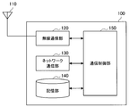
- FIG. 2 is a block diagram showing an example of the configuration of the base station 100 according to the embodiment of the present disclosure.
- the base station 100 includes an antenna unit 110, a wireless communication unit 120, a network communication unit 130, a storage unit 140, and a communication control unit 150.
- Antenna unit 110 The antenna unit 110 radiates the signal output by the wireless communication unit 120 into space as a radio wave. Further, the antenna unit 110 converts a radio wave in space into a signal and outputs the signal to the wireless communication unit 120.
- the wireless communication unit 120 transmits and receives signals. For example, the wireless communication unit 120 transmits a downlink signal to the terminal device and receives the uplink signal from the terminal device.
- the network communication unit 130 transmits / receives information.
- the network communication unit 130 transmits information to another node and receives information from the other node.
- the other nodes include other base stations and core network nodes.
- the terminal device may operate as a relay terminal and relay the communication between the remote terminal and the base station.
- the wireless communication device 100C corresponding to the relay terminal may not include the network communication unit 130.
- Storage unit 140 The storage unit 140 temporarily or permanently stores the program and various data for the operation of the base station 100.
- the communication control unit 150 controls the operation of the wireless communication unit 120 to control communication with another device (for example, the terminal device 200) via a wireless communication path.
- the communication control unit 150 generates a transmission signal by modulating the data to be transmitted based on a predetermined modulation method, and transmits the transmission signal to the wireless communication unit 120 to the terminal device 200 in the cell. You may send it to.
- the communication control unit 150 acquires the reception result (that is, the received signal) of the signal from the terminal device 200 from the wireless communication unit 120, and performs a predetermined demodulation process on the received signal.
- the data transmitted from the terminal device 200 may be demodulated.
- the communication control unit 150 may control communication between other base stations 100 and each entity constituting the core net by controlling the operation of the network communication unit 130.
- each configuration of the base station 100 is merely an example, and does not necessarily limit the functional configuration of the base station 100.
- a part of each configuration of the base station 100 may be provided outside the base station 100.
- each function of the base station 100 may be realized by operating a plurality of devices in cooperation with each other.
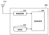
- FIG. 3 is a block diagram showing an example of the configuration of the terminal device 200 according to the embodiment of the present disclosure.
- the terminal device 200 includes an antenna unit 210, a wireless communication unit 220, a storage unit 230, and a communication control unit 240.
- Antenna unit 210 The antenna unit 210 radiates the signal output by the wireless communication unit 220 into space as a radio wave. Further, the antenna unit 210 converts the radio wave in the space into a signal and outputs the signal to the wireless communication unit 220.
- the antenna unit 210 may include a plurality of antenna elements.
- the wireless communication unit 220 transmits and receives signals. For example, the wireless communication unit 220 receives the downlink signal from the base station and transmits the uplink signal to the base station.
- the terminal device may operate as a relay terminal and relay the communication between the remote terminal and the base station.
- the wireless communication unit 220 in the terminal device 200C operating as a remote terminal may transmit and receive a side link signal to and from the relay terminal.
- Storage unit 230 The storage unit 230 temporarily or permanently stores the program and various data for the operation of the terminal device 200.
- the communication control unit 240 controls the operation of the wireless communication unit 220 to control communication with another device (for example, the base station 100) via a wireless communication path.
- the communication control unit 240 generates a transmission signal by modulating the data to be transmitted based on a predetermined modulation method, and transmits the transmission signal to the wireless communication unit 220 toward the base station 100. You may let me.
- the communication control unit 240 acquires the reception result (that is, the received signal) of the signal from the base station 100 from the wireless communication unit 220, and performs a predetermined demodulation process on the received signal.
- the data transmitted from the base station 100 may be demodulated.
- the configuration of the terminal device 200 described above with reference to FIG. 3 is merely an example, and does not necessarily limit the functional configuration of the terminal device 200.
- a part of each configuration of the terminal device 200 may be provided outside the terminal device 200.
- at least one of the antenna unit 210, the wireless communication unit 220, and the storage unit 230 shown in FIG. 3 may be externally attached to the terminal device 200.
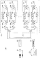
- FIG. 4 is a block diagram showing an example of the configuration of the antenna device 250 according to the embodiment of the present disclosure, and shows an example of the configuration of the antenna device configured so that the directivity of the radio signal can be controlled by the beamforming technique.
- FIG. 4 shows a configuration of a portion corresponding to the antenna unit 210 in the example shown in FIG. 3 and a portion of the communication control unit 240 related to the control of the antenna unit 210. An example is shown.
- the antenna device 250 includes a plurality of antenna units 255, a mixer 251, an RF distributor (synthesizer) 253, a storage unit 230, and a communication control unit 241.
- the antenna device 250 shown in FIG. 4 is configured to be capable of transmitting V-polarized wave and H-polarized wave as wireless signals. That is, in FIG. 4, the IF_V signal and the IF_H signal indicate a signal corresponding to V polarization and a signal corresponding to H polarization among analog signals corresponding to the modulation result of the data to be transmitted. ing. Further, the LO signal schematically shows an output signal from a local oscillator (Local Oscillator) used for converting an IF_V signal and an IF_H signal into a millimeter-wave RF signal.
- a local oscillator Local Oscillator
- each of the IF_V signal and the IF_H signal is converted into a millimeter-wave RF signal by being mixed with the LO signal by the mixer 251. Then, each of the IF_V signal and the IF_H signal converted into the millimeter wave RF signal is supplied to each antenna unit 255 by the RF distributor (synthesizer) 253.
- the antenna unit 255 schematically shows a configuration including a plurality of antenna elements included in the antenna device 250 and a circuit group for transmitting and receiving radio signals via the antenna elements.
- the antenna unit 255 schematically shows a portion corresponding to each patch antenna.
- the antenna unit 255 includes two systems, one for transmitting and receiving I polarization and the other for transmitting and receiving H polarization among the radio signals transmitted and received. It should be noted that each of these configurations has substantially the same configuration except that the polarization to be transmitted is different. Therefore, in the following, only the configuration related to the transmission / reception of one polarized wave will be described, and the detailed description of the configuration related to the transmission / reception of the other polarized wave will be omitted.
- the configuration for transmitting each polarized wave includes a phase device 257, RF switches 259a and 259b, amplifiers 261 and 263, and an antenna element 265.
- the antenna element 265 schematically shows a portion of the antenna element included in the antenna unit 255 related to transmission / reception of the target polarized wave.
- the antenna element 265 schematically shows a portion of the flat plate antenna element related to the transmission of the target polarized light. .. That is, the antenna element 265 radiates the millimeter-wave RF signal (transmission signal) supplied from the RF switch 259b side into space as a radio wave (radio signal). Further, the antenna element 265 converts a radio wave in space into a millimeter wave RF signal (received signal), and supplies the millimeter wave RF signal to the RF switch 259 side.
- the phase device 257 controls the phase of the input signal. Specifically, the millimeter-wave RF signal (transmission signal) to be transmitted is input to the phase device 257 from the RF distributor (synthesis) device 253 side, the phase is adjusted by the phase device 257, and then the RF switch is used. It is input to 259a. Further, the millimeter-wave RF signal (received signal) obtained by converting the radio wave in space by the antenna element 265 is input to the phase device 257 from the RF switch 259a side, the phase is adjusted by the phase device 257, and then RF distribution is performed. It is input to the (synthesis) device 253.
- Each of the amplifiers 261 and 263 amplifies the input signal (millimeter wave RF signal). Specifically, the amplifier 261 amplifies the transmission signal. The amplifier 263 also amplifies the received signal. Further, each of the amplifiers 261 and 263 may be configured to be able to control the gain related to the amplification of the signal.
- the RF switches 259a and 259b switch the path through which the millimeter-wave RF signal is propagated. Specifically, when the antenna unit 255 transmits a radio signal, the RF switches 259a and 259b so that the transmission signal output from the phase device 257 is supplied to the antenna element 265 via the amplifier 261. Controls the route through which the transmitted signal is propagated. Further, when the antenna unit 255 receives the radio signal, the RF switches 259a and 259b so that the received signal obtained by converting the radio wave in space by the antenna element 265 is supplied to the phase controller 257 via the amplifier 263. In addition, the route through which the received signal is propagated is controlled.
- the communication control unit 241 controls the phase of the millimeter-wave RF signal input to the phase device 257 by controlling the operation of each phase device 257 included in each antenna unit 255. Further, the communication control unit 241 may control the gain related to the amplification of the signal by the amplifiers 261 and 263 included in each antenna unit 255. With such a configuration, for example, the communication control unit 241 controls the directivity of the beam related to the transmission of the radio signal by the antenna device 250 by individually controlling each phase device 257 included in each antenna unit 255. Is possible. Further, at this time, the communication control unit 241 may individually control the operation of the amplifier 261 included in each antenna unit 255.
- the communication control unit 241 can control the directivity of the beam related to the reception of the radio signal by the antenna device 250 by individually controlling each phase device 257 included in each antenna unit 255. Further, at this time, the communication control unit 241 may individually control the operation of the amplifier 263 included in each antenna unit 255.
- the communication control unit 241 controls each antenna from the LUT (Lookup Table) held in the storage unit 230 when controlling the operation of at least one of the phase device 257, the amplifier 261 and the amplifier 263 included in each antenna unit 255. Information specific to the unit 255 may be read out and used. With such a configuration, the communication control unit 241 has a delay caused by a factor peculiar to each antenna unit 255 (for example, a delay caused by a difference in the wiring length of the millimeter wave antenna element on the substrate) and the like. It is possible to reduce (and thus suppress) the influence of. The details of the LUT will be described later. Further, the LUT corresponds to an example of "control information" for controlling the directivity of the radio signal transmitted from the antenna device.
- the LUT corresponds to an example of "control information" for controlling the directivity of the radio signal transmitted from the antenna device.
- FIG. 5 is a diagram showing an example of a system configuration of a mobile communication system assumed in NSA.
- C-plane control information
- U-plane user data
- the 5G RAN Radio Access Network
- millimeter wave such as 28 GHz or 39 GHz
- millimeter wave a radio signal having a frequency called millimeter wave
- millimeter waves have a relatively large spatial attenuation, and when millimeter waves are used for communication, an antenna having a high gain tends to be required.
- a directional beam is formed by a technique called beamforming, so that the directional beam is used for communication between a base station and a terminal device. It is being considered to use it.
- communication between a base station and a terminal device can be spatially multiplexed in addition to temporal and frequency multiplexing.
- eMBB enhanced Mobile Broad. Band
- FIG. 6 is an explanatory diagram for explaining an outline of an example of cell arrangement design in 5G.
- an existing cell 10A based on the LTE standard is used as an overlaid cell, and small cells 10B # 1 to 10B # 3 capable of communicating using millimeter waves in the cell 10A. Overlap to form a heterogeneous network (HetNet).
- the small cells 10B # 1 to 10B # 3 indicate the small cells formed by the small cell base stations 100B # 1 to 100B # 3, respectively.
- Beam management Next, the procedure of beam management (BM: Beam Management) in 5G will be described with particular attention to the procedure for narrowing the beam used for communication between the base station and the terminal device.
- 5G (NR) using the millimeter wave band is called FR2 (24.25G to 52.6GHz) from the frequency range in the specifications, and in TS38.101-2 (2018/09), the terminal device (5G terminal) Specifications have been made for the test items of the radio characteristics on the side and the minimum requirements for the test items.
- FR2 5G NR
- the coverage of one base station for example, eNB, gNB, TRP, etc.
- the radio waves radiated from the antenna are concentrated in a desired direction to form a narrow beam width so as to have sharp directivity.
- FR2 5G (NR) adopts the TDD method, and ping-pong transmission communication with the same frequency is performed together with the DL signal and UL signal. Therefore, the beamforming function for compensating for the path loss in FR2 described above may be required not only on the base station side but also on the terminal device (5G terminal) side.
- BM Beam Management
- FIG. 7 is an explanatory diagram for explaining the outline of the beam management procedure.
- BM beam management
- P1, P2, and P3 procedures the operation of beam management (BM) represented by the P1, P2, and P3 procedures is defined as the procedure for narrow beam formation.
- BR Beam Refinement
- the beam refinement (BR: Beam Refinement) between the base station and the terminal device is performed by the P1, P2, and P3 procedures.
- the P1 procedure is defined by beam selection (Beam selection) and beam reselection (Beam reselection).
- Beam selection Beam selection
- Beam reselection Beam reselection
- Beam Alignment Beam Alignment
- the P2 procedure is defined by Tx beam refinement.
- the beam is refined (BR) for the DL (Downlink) Tx beam on the base station side, and the beam width is narrowed between the narrow beam on the base station side and the beam on the terminal device side. It is assumed that the alignment (Beam correspondence) will be performed at.
- the P3 procedure is defined by Rx beam refinement.
- beam refinement (BR) is performed for the DL Rx beam on the terminal device side, and the narrow beam on the base station side and the narrow beam on the terminal device side with a narrower beam width are used. It is assumed that the alignment (Beam correspondence) will be performed.
- FR2 5G NR
- the number of beams formed by a plurality of antenna elements included in the antenna device mounted on the terminal device and the phase and power characteristics of the beams depend on the form factor of the terminal device itself, the terminal design, and the terminal design. May be done. As an example of specific factors, the characteristics of the antenna element included in the antenna device mounted on the terminal device, how many antenna devices are provided per terminal device (5G terminal), and the position of the terminal where the antenna device is arranged. The material of the material used for the terminal itself, what the design of the terminal is, and so on.
- the influence of the above-mentioned factors unique to the terminal device is taken into consideration. It may be necessary to control the phase and power associated with the transmission of the signal.
- the information related to such phase and power control is, for example, a series of information obtained by measuring each beam in advance and associating each beam with the information acquired for the beam.
- So-called LUT Lookup Table
- LUT Lookup Table
- the terminal device is unique to the terminal device described above by controlling the phase and power related to the transmission of the radio signal from each antenna element included in the desired antenna device by using the information held in the LUT. It is possible to reduce the influence of the above factors.
- the phase and power related to the transmission of the radio signal by each antenna element included in the antenna device at the time of forming the beam are measured. Is required. If the terminal device includes four antenna devices, it is necessary to measure the phase and power related to the transmission of the radio signal by each antenna element for each beam that can be formed by the antenna device for each antenna device. Therefore, the measurement time of the data related to the control of the phase and the power for creating the LUT becomes relatively long. In such a situation where the measurement takes a long time, the IF signal (that is, the IF_V signal and the IF_H signal shown in FIG.
- each element for example, an amplifier
- the LO is affected by the heat dissipation of each element (for example, an amplifier) included in the antenna device.
- each element for example, an amplifier
- 5G (NR) using the millimeter wave band adopts the TDD method, and both DL signal and UL signal communicate by ping-pong transmission at the same frequency. Therefore, the beamforming function for compensating for the path loss in FR2 may be required not only on the base station side but also on the terminal device (5G terminal) side.
- the base station side and the terminal device (5G terminal) side have the ability (Capability) to align the spatial positions of the beams with each other.
- the ability to align the spatial position of the beam is called Beam Correspondence (BC). That is, it is important that the terminal device (5G terminal) side in FR2 has this capability in order to quickly and stably communicate with the base station side in the millimeter wave band.
- the above-mentioned Capability of Beam Correspondence is described in Section 6.6 Beam correspondence of TS38.101-2 of 3GPP.
- test items are disclosed as core specifications that are the minimum requirements for UE RF characteristics.
- the terminal device (5G terminal) can have the above-mentioned beam correspondence capability by holding the above-mentioned LUT generated as described above so as to be able to refer to the antenna device provided by the terminal device (5G terminal). ..
- the generation of the LUT is particularly preferable.
- the measurement system is configured so that the DUT (UE) and the measurement antenna are separated by a distance R, which is a distant field in which the electromagnetic wave is directly regarded as a plane wave.
- the distance R is represented by the calculation formula shown below as (Equation 1).
- R indicates the minimum far field distance.
- ⁇ indicates the wavelength of the radio signal whose RF characteristic is to be measured (that is, the wavelength of the radio signal corresponding to the frequency whose RF characteristic is to be measured).
- D indicates the diameter of the minimum sphere surrounding the radiating portion of the DUT.
- D for example, the diagonal length of the housing of the terminal device (5G terminal) is used. In a general smartphone, the length of the diagonal line tends to be about 15 cm. Further, in the case of a tablet terminal, the length of the diagonal line tends to be about 30 cm.
- the formula for calculating the distance that can be regarded as a distant field and the free space loss derived from the distance are disclosed in, for example, TR38.810 of 3GPP.
- the size of the anechoic chamber that can be regarded as a distant field tends to be relatively large, and the free space loss tends to be large.
- NFTF NFTF
- the conversion from the near field to the far field is performed.
- the 3D far-field pattern is obtained by using the spherical wave extension of the modal analysis, and the transformation between the near-field and the far-field is based on the Huygens principle.
- the direct solution of the Helmholtz equation is obtained by applying boundary conditions at infinity from the DUT to the surface.
- the mode coefficient can be determined from the tangent field on the surface of the sphere using the orthogonality of the mode expansion. Details of this matter are disclosed in Annex F of TR38.810.
- NFTF In the measurement of NFTF, it is possible to measure a 3D pattern accompanied by rotation of the azimuth angle (azimuth direction) by using a circular probe array. Further, by utilizing the electronic switching between the antenna elements of the probe array, it is possible to measure the point of the elevation angle (elevation direction) without rotating the DUT in the elevation angle plane.
- the signal transmitted by the DUT is measured simultaneously using two probes. At this time, one corresponds to the probe for the measurement signal and the other corresponds to the probe for the reference signal. Based on such a configuration, the amplitude and absolute phase of the measurement signal are acquired by inputting the measurement results of the measurement signal and the reference signal by the above two probes to the PRU (Phase Recovery Unit). ..
- the NFTF method tends to complicate the measurement system due to the characteristic of using PRF.
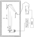
- FIG. 8 is an explanatory diagram for explaining an example of a measurement system to which the IFF method is applied, and shows an example of a configuration of a so-called CATR measurement system (hereinafter, also simply referred to as “CATR”).
- CATR CATR measurement system
- the CATR shown in FIG. 8 has the following features. It is possible to provide a positioning system that has at least two degrees of freedom of rotation at an angle between the dual polarization measurement antenna and the DUT and maintains a polarization reference. -It has been agreed in 3GPP TR38.810 that test items for EIRP, TRP, EIS, EVM, spurious emission, and blocking can be tested. -Before executing the beam lock function (UBF), the measuring antenna probe functions as a link antenna for maintaining a polarization reference with respect to the DUT.
- UPF beam lock function
- the link with the SS (gNB emulator) side is passed to the link antenna side, and the link antenna can maintain a reliable signal level with respect to the DUT.
- the link antenna can maintain a reliable signal level with respect to the DUT.
- CATR as shown in FIG. 8 is generally used as a standard measurement system for the OTA (Over The Air) test method of UE RF characteristics in 5G (NR) of FR2.
- the DUT radiates a spherical wave surface to a collimator (a system that parallelizes radio waves) that is within the range of focusing the propagation vector that coincides with the bore site direction of the reflector on the feed antenna.
- the feeding antenna radiates a spherical wave surface to a reflector in a range in which radio waves are parallel to the DUT direction. That is, the CATR is a system that converts the spherical wave surface into a plane wave surface when the spherical wave surface is on the DUT side.
- a plane wave plane (having uniform amplitude and phase) is a measurement system guaranteed for a specific cylinder size.
- the size of the QZ depends mainly on the reflector, the taper of the feed antenna, and the design of the anechoic chamber.
- the details of the concept of QZ in CATR and an example of the phase distribution in QZ of CATR designed for QZ size are disclosed in TR38.810 of 3GPP, so detailed description thereof will be omitted. ..
- the total phase variation in QZ of CATR is characterized by being extremely smaller than the phase variation (22.5 degrees) with respect to general DFF.
- the NR RF FR2 requirement CATR includes a link antenna for maintaining the NR link that enables off-center beam measurement.
- this link antenna makes it possible to measure the entire emission pattern of UE RF characteristics at 5G (NR) of FR2.
- NR 5G
- the antenna probe for measurement functions as a link antenna that maintains a polarization reference with respect to the DUT.
- SS System Simulator
- UE terminal device
- the link antenna and the beam lock test function on the terminal device side allow the CATR to perform beam measurement on both the beam center side and the beam off-center side.
- the link on the LTE side is set to the DUT side by using the link antenna for LTE as an anchor. It is possible to provide.
- Link antennas for LTE provide stable LTE signals without accurate path loss or polarization control.
- the CATR is provided with such a link antenna for LTE.
- FIG. 9 is an explanatory diagram for explaining an example of the EIPR measurement system using the CATR measurement system, and shows an example of the EIPR measurement system at the time of non-standalone.
- a general measurement procedure will be described below.
- the terminal device (UE) side that has entered the test mode by the test SIM performs almost the same operation as during IA during normal operation, and uses the antenna module group provided on the terminal device side to perform an NR system simulator (Stars search reception of "SS Block” sent from the SS) side.
- the "threshold information" of "SS Block” to be selected for the RSRP received by each antenna module from the LTE side of the anchor for the terminal device and the gNB side.
- Tx transmission power information and is transmitted.
- the "Tx-Rx Reciprocity characteristic" is sufficiently established in the anechoic chamber chamber, so the direction in which the RSRP measurement result is the largest is set as the beam peak direction on the Tx-Rx side. It is possible to decide. It is agreed in 3GPP that the beam direction of PRACH is QCL (spatial) with "SS Block" having the largest RSRP value.
- the terminal device (5G terminal) side uses a test SIM, but operates in almost the same way as during normal IA, receives the SS Block signal from the NR system simulator, and uses the EN-DC (NSA) anchor. Obtain “SIB1" information from the LTE side. Then, the terminal device performs a beamforming (BF) operation so that the RSRP value of the "SIB1" information is maximized. Specifically, the terminal device controls the direction in which the peak beam is directed so as to satisfy the beam correspondence (BC) characteristic from the optimum antenna module.
- BF beamforming
- the Tx-Rx side beam peak direction is detected.
- the transmission output is increased until the Tx peak beam is formed in the direction specified above by "UL RMC setting” and "Power control by TPC” according to the DCI format.
- UBF Beam Lock
- the above measurement is performed for each of the V-polarized wave and the H-polarized wave for each frequency that is the target of FR2.
- FIG. 10 is an explanatory diagram for explaining an example of the EIPR measurement system using the CATR measurement system, and shows an example of the EIPR measurement system at the time of stand-alone.
- the NR RF FR2 requirement CATR measurement system includes a link antenna for maintaining the NR link in order to enable off-center beam measurement. That is, in the measurement of UE RF characteristics in the non-standalone (NSA) mode using the 1UL setting, by using the LTE link antenna that serves as an anchor in advance, the terminal device (5G terminal) side and the LTE that serves as an anchor can be used. Therefore, the "CONNECTED" state is maintained, and the link with the LTE system simulator (SS) side is maintained.
- NSA non-standalone
- the terminal device (5G terminal) side in the measurement of UE RF characteristics in the stand-alone (SA) mode, generally corresponds to both the Sub6 (FR1) and millimeter-wave band (FR2) bands. It is reasonable enough to think that it is. Therefore, in the measurement of UE RF characteristics in the non-standalone (NSA) mode using the above-mentioned 1UL setting, by using the LTE link antenna that serves as an anchor in advance, the terminal device (5G terminal) side and the LTE that serves as an anchor The system simulator on the side uses the same concept as when the "CONNECTED" state is maintained.
- the 5G (NR) FR1 in the 3GPP specifications operates in the same frequency band as LTE (for example, 7.125 GHz or less). Therefore, in general, the antenna on the terminal device (5G terminal) side can have an omni pattern.
- the 5G (NR) side of FR1 whose antenna has an omni pattern first is in the "CONNECTED" state with the NR system simulator SS side. The call connection is made until.
- the NR system simulator side of FR1 inside the measurement system of the anechoic chamber as well as the LTE side which is the anchor of the non-standalone (NSA) mode. That is, as in the non-standalone (NSA) mode, off-center beam measurement of UE RF characteristics in 5G (NR) of FR2 becomes possible.
- EIRP measurement and the like can be performed in both the non-standalone (NSA) mode and the stand-alone (SA) mode.
- a common reference CLK (Ref_CLK) is used between the NR system simulator side for FR2 where beam forming is performed and the measuring instrument on the LTE system simulator side which is an anchor in NSA.
- Ref_CLK a common reference CLK
- the terminal device (5G terminal) side having an omni-pattern antenna is stable with respect to the measuring instruments on the LTE system simulator side and the NR system simulator side for FR1. It is possible to maintain a link with the measuring instrument side. Therefore, the CE (Channel Estimation) function and frequency tracking function of the BB (Base Band) modem inside the terminal device (5G terminal) operate autonomously, and the frequency is affected by heat dissipation due to the long measurement time. Even in a situation where a deviation can occur, the deviation of the frequency is autonomously compensated by the terminal device itself.
- CE Channel Estimation
- BB Base Band
- TS36.101 which is a specification that describes the core specifications of LTE RF characteristics
- TS38.101 which is a specification that describes the core specifications of 5G (NR) RF characteristics
- an omni-pattern antenna is provided for the measuring instrument on the LTE system simulator side and the FR1 NR system simulator side in the measurement system in the anechoic chamber.
- the terminal device (5G terminal) side can stably maintain a link with the measuring instrument side. That is, even in a situation where the CE (Channel Optimization) function and the frequency tracking function of the BB modem inside the terminal device (5G terminal) may cause a frequency shift due to the influence of heat dissipation due to a long measurement time. The frequency shift is autonomously compensated by the terminal device itself.
- the influence of frequency shift due to heat dissipation (for example, phase shift of wireless signals) can be suppressed, and complicated operations are not required.
- a mechanism that enables the generation of the above-mentioned LUT.
- the terminal device As mentioned above, when performing the conformance test of UE RF characteristics in 3GPP, the "Black Box approach" that does not declare the location of the antenna device on the terminal device (5G terminal) side is currently agreed on in RAN4 and RAN5. Has been done.
- the terminal device (UE) vendor side When the terminal device (UE) vendor side generates a LUT peculiar to the antenna device provided in the terminal device, the position where the antenna device is arranged can be clearly grasped. In the system according to the present embodiment, such a characteristic is used to generate a LUT peculiar to the antenna device provided in the terminal device.
- the terminal device will be provided with four antenna devices as shown in the example shown in FIG. 7. Further, with respect to the antenna device, as shown in the example shown in FIG. 4, each antenna element is configured to be able to transmit and receive V-polarized light and H-polarized wave, and the four antenna elements are arranged in an array. And.
- VNA vector network analyzer
- the 5G (NR) BB modem side has, for example, a setting for operating in a special test mode as a development test function.
- a LUT for millimeter wave (FR2) is created for a non-standalone (NSA) mode and a stand-alone (SA) mode terminal device (5G terminal) will be described.
- the system simulator side for LTE, which is an anchor, and the "CONNECTED" state are first maintained, and then the antenna included in the antenna device is provided for each beam formed by each antenna device included in the terminal device.
- test mode for measuring the phase and power of the radio signal transmitted by the element is set for each of the measuring instrument side and the terminal device (5G terminal) side in the measurement system of the CATR.
- SA mode first, as an Inter-band CA, the NR system simulator side of FR1 and the "CONNECTED" state are maintained, and then the antenna is formed for each beam formed by each antenna device provided in the terminal device.
- a test mode for measuring the phase and power of the radio signal transmitted by the antenna element included in the device is set for each of the measuring device side and the terminal device (5G terminal) side in the measurement system of the CATR. It shall be.
- a CW (Continuous Wave) signal which is an unmodulated carrier, is used as a signal for operating the antenna device in the same manner as the signal output from the VNA described above. It is assumed that the output is from the 5G (NR) BB modem side.
- the phase shifter inside the antenna device for millimeter waves is operating according to the IC design, and the antenna element included in the antenna device is provided for each beam formed by each antenna device.
- the phase and power of the radio signal transmitted by is measured.
- the QZ of the CATR has a cylindrical shape, and the amount of phase fluctuation in the QZ is smaller than the amount of phase fluctuation in the case of DFF.
- a CATR measurement system having a QZ with a diameter of 30 cm has already been put into practical use.
- VSA vector signal analyzer
- the antenna element included in the antenna device is provided for each beam that can be formed by the antenna device mounted on the terminal device (5G terminal) by using the VSA to which the high-speed ADC described above is applied in the CATR measurement system.
- the radio signal phase and amplitude (power) transmitted by each are measured.
- the above measurement is performed while changing the posture of the terminal device (in other words, the antenna device) in the azimuth direction and the elevation direction with a measurement grid having a predetermined step size.
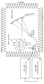
- FIG. 11 is an explanatory diagram for explaining an example of the configuration of the information processing system according to the embodiment of the present disclosure.
- the information processing system (that is, the measurement system) 10 includes a terminal device 200, an attitude control device 281, a position controller 283, a reflector 285, a feed antenna 287, and the like. It includes a link antenna 289 for LTE, a vector signal analyzer (VSA) 291, a system simulator 293 for LTE, and a control device 295.
- VSA vector signal analyzer
- the attitude control device 281 includes a support portion configured to support the terminal device 200. Further, the support portion is supported by a member configured to be rotatable with respect to each of a plurality of rotation axes different from each other. Based on such a configuration, the posture of the support portion is controlled by rotationally driving the member by driving an actuator or the like. That is, the posture of the terminal device 200 supported by the support portion is controlled.
- the operation of the attitude control device 281 is controlled by, for example, the position controller 283 described later.
- the reflector 285 corresponds to a reflector for indirectly forming a far-field environment in the IFF measurement system.
- the reflector 285 is arranged so as to face the terminal device 200 supported by the attitude control device 281 at a predetermined distance. Based on such a configuration, the reflector 285 reflects the radio signal transmitted from the antenna device included in the terminal device 200 toward the feed antenna 287.
- the feed antenna 287 receives the radio signal transmitted by the antenna device included in the terminal device 200 and then reflected by the reflector 285, and outputs the reception result to the vector signal analyzer 291.
- the LTE system simulator 293 and the LTE link antenna 289 play a role as the LTE system simulator and the LTE link antenna described with reference to FIG. That is, by using the LTE link antenna 289 as an anchor and maintaining the "CONNECTED" state with respect to the terminal device 200 and the LTE as an anchor, the link between the terminal device 200 and the LTE system simulator 293 is maintained. Dripping. That is, the LTE system simulator 293 autonomously performs wireless communication (LTE) with the terminal device 200 via the LTE link antenna 289 so that the frequency error is within ⁇ 0.1 PPM as described above. By operating, it is possible to solve the problem of phase measurement due to frequency shift due to heat dissipation of the element included in the antenna device. Further, the LTE system simulator 293 supplies the vector signal analyzer 291 with a control signal according to the control content of the operation of the terminal device 200, thereby notifying the vector signal analyzer 291 of information regarding the control of the terminal device 200. Is also possible.
- CRS Cell Specific
- DMRS Demodulation
- the LTE system simulator 293 is supplied with the same reference clock (Ref_CLK) as the vector signal analyzer 291 in the measurement system. It can be seen from the above-mentioned measurement system that the vector signal analyzer 291 and the LTE system simulator 293 and the terminal device 200 are always compensated to be synchronized in both the frequency domain and the time domain.
- a CW signal which is an unmodulated carrier
- the IF_V bias is applied in the terminal device 200. It becomes a wave signal and an IF_H polarization signal.
- the terminal device 200 and the vector signal analyzer 291 can be synchronized with the timing related to the transmission of the CW signal which is the unmodulated carrier which is the test mode signal.
- the vector signal analyzer 291 acquires the reception result of the radio signal from the feed antenna 287 and measures the phase and amplitude of the radio signal. As described above, since the entire measurement system is time-synchronized, the vector signal analyzer 291 always recognizes the transmission timing of the CW signal, which is the unmodulated carrier, which is the test mode signal by the terminal device 200. is made of. Of course, if the vector signal analyzer 291 can measure the phase of the CW radio signal based on the reception result of the CW signal which is the unmodulated carrier, the method is not limited to the above-mentioned example. Then, the vector signal analyzer 291 outputs the measurement result of the phase and the amplitude of the radio signal to the control device 295.
- the position controller 283 controls the attitude of the terminal device 200 supported by the support portion of the attitude control device 281 by controlling the operation of the attitude control device 281.
- the terminal device 200 for the reflector 285 is controlled. That is, with the control of the attitude control device 281 by the position controller 283, one of the plurality of antenna devices included in the terminal device 200 is controlled so as to face the reflector 285, and the reflection is performed.
- the attitude of the antenna device with respect to the plate 285 is controlled.
- the control device 295 controls the operation related to the measurement of the phase and amplitude of the radio signal transmitted from the antenna device of the terminal device 200, and generates the LUT specific to the antenna device based on the measurement result.
- the control device 295 attaches the attitude control device to the position controller 283 so that the antenna device to be measured among the plurality of antenna devices included in the terminal device 200 is in a state of facing the reflector 285.
- the operation of 281 is controlled.
- the control device 295 causes the position controller 283 to control the operation of the attitude control device 281 so that the attitude of the antenna device with respect to the reflector 285 is controlled according to the direction in which the antenna device forms a beam. You may.
- control device 295 instructs the vector signal analyzer 291 to perform an operation related to the measurement of the phase and amplitude of the radio signal transmitted by the target antenna device.
- the vector signal analyzer 291 operates in cooperation with the LTE system simulator 293 to execute a series of processes related to the above-mentioned measurement.
- control device 295 acquires information according to the measurement results of the phase and amplitude from the vector signal analyzer 291, the control device 295 uses the information as information on the antenna device set as the measurement target at that time and information on the attitude of the antenna device.
- the LUT is generated by associating it with (in other words, information about the direction in which the directivity of the beam is directed). The details of the operation related to the above-mentioned series of measurements and the operation related to the generation of the LUT according to the result of the measurement will be described later. Further, the control device 295 corresponds to an example of the "information processing device" related to the generation of the LUT.
- the vendor side of the terminal device can grasp the location of the antenna device on the terminal device (5G terminal) side. Therefore, for example, the posture of the antenna device can be finely adjusted so that the measured value of the power of the beam formed by the antenna device by the vector signal analyzer 291 is maximized.
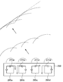
- FIG. 12 is an explanatory diagram for explaining an example of the configuration of the antenna device included in the terminal device according to the present embodiment.
- the antenna device 250 shown in FIG. 12 includes antenna elements 265a to 255d configured as a patch antenna (plane antenna).
- antenna elements 265a to 255d when the antenna elements 265a to 255d are not particularly distinguished, they may be referred to as "antenna element 265".
- the antenna element 265 is configured to be capable of transmitting V-polarized light and H-polarized wave.
- reference numerals 271a to 271d schematically indicate wiring for transmitting an electric signal related to transmission of a radio signal to each feeding point of the antenna elements 265a to 255d.
- any one of the antenna elements 265a to 255d is set as the reference antenna element 265.
- the phase and power of the radio signal measured for the reference antenna element 265 are set as reference values related to the measurement of the phase and power of the radio signal for the other antenna element 265.
- the phase and power measurements are acquired as deviation measurements with respect to the reference value (ie, relative to the reference value).
- the method of determining the reference antenna element 265 from the plurality of antenna elements 265 (for example, the antenna elements 265a to 255d) included in the antenna device 250 is not particularly limited.
- the antenna element 265b (hereinafter, also referred to as “Patch 2”) is set as a reference.
- the antenna element 265 included in the reference antenna element 265b corresponds to an example of the "first antenna element”.
- the information corresponding to the reference value corresponds to an example of the "first information”.
- a radio signal is transmitted from the antenna element 265b (Patch2), and the vector signal analyzer 291 is made to measure the phase and amplitude of the V polarization of the radio signal.
- the measurement results of the phase and amplitude (power) are retained as reference values.
- the settings of the CATR measurement system and the 5G (NR) BB modem side are controlled in advance so that the polarization plane of the antenna element 265 is used for the radiation signal of V polarization.
- a radio signal is transmitted from the antenna element 265a (hereinafter, also referred to as “Patch 1”), and the vector signal analyzer 291 is made to measure the phase and amplitude (power) deviation of the V polarization of the radio signal with respect to the reference value.
- the antenna element 265c hereinafter, also referred to as “Patch3”
- the antenna element 265d hereinafter, also referred to as “Patch4”
- the vector signal analyzer 291 is made to transmit the radio signal with respect to the reference value.
- the phase and amplitude (power) deviation of the V polarization of the signal are measured.
- An antenna element 265 other than the reference antenna element 265b, such as the antenna element 265a, corresponds to an example of the “second antenna element”. Further, the information according to the measurement result of the phase and amplitude (power) deviation corresponds to an example of "second information" about the antenna element 265a.
- the other antenna element 265 may be invalidated when the above measurement is performed for each antenna element 265. That is, the above measurement may be performed for each antenna element 265 while sequentially enabling each of the antenna elements 265b, 255a, 255c, and 255d.
- a radio signal is transmitted from the antenna element 265b, and the vector signal analyzer 291 is made to measure the phase and amplitude of the H polarization of the radio signal.
- the measurement results of the phase and amplitude (power) are retained as reference values.
- a radio signal is transmitted for each of the antenna elements 265a, 255c, and 255d, and the vector signal analyzer 291 is made to measure the phase and amplitude (power) deviation of the H polarization of the radio signal with respect to the reference value.
- the phases and amplitudes of V-polarized light and H-polarized light are measured for the antenna elements 265a to 255d included in the target antenna device 250.
- the posture of the antenna device 250 is adjusted for each measurement grid having a predetermined step size in the azimuth direction and the elevation direction, and is executed for each posture. That is, for one antenna device, the measurement results of the phases and amplitudes of V-polarized light and H-polarized light are acquired for the antenna elements 265a to 255d for each attitude in the azimuth direction and the elevation direction.
- the measurement results acquired at this time are the measurement results of the phase and amplitude (power) of the V-polarized light and the H-polarized light transmitted from the reference antenna element 265b, and the measurement results as reference values.
- the measurement results of the phase and amplitude deviations of the V-polarized light and the H-polarized light transmitted from the antenna elements 265a, 255c, and 255d, respectively, are included.
- the antenna device 250 shown in FIG. 12 is configured to be capable of transmitting V-polarized light and H-polarized wave, and includes four antenna elements 265. Further, the antenna device 250 is composed of each TXRU (Tx & Rx chain) including a plurality of antenna elements (for example, four antenna elements) as in the example described with reference to FIG.
- a line routing (Feed line) to the feeding point of each antenna element 265 occurs due to the influence of size restrictions in the configuration and the like.
- the form factor, peripheral members, materials, etc. of the terminal device 200 itself may differ depending on the position of the terminal device 200 in which the antenna device 250 for millimeter waves is arranged.
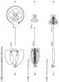
- FIG. 12 shows the principle of controlling the spatial position of the beam in the assumed direction (beam steering).
- the absolute phase and amplitude (power) values of the radio signal which is a millimeter wave transmitted from each of the four antenna elements 265, are not particularly required, and are configured as shown in FIG.
- each TXRU Tx & Rx chain
- the total measurement time and the accuracy related to the beam formation by each antenna device provided in the terminal device (in other words, the accuracy of phase and amplitude compensation based on the LUT). ) And, it is decided by the trade-off.
- the trade-off As a specific example, when measuring the phase and power of a radio signal which is a millimeter wave for each antenna element included in each antenna device included in the terminal device with a measurement grid having a step size of 3 degrees. In proportion to the number of measurement points, the accuracy of beam formation during beamforming improves, but the measurement time becomes longer.
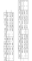
- FIG. 13 shows an example of the measurement results of the phase and power of the antenna device related to the generation of the LUT according to this embodiment.
- the measurement result of the antenna element 265b (Patch2) among the antenna elements 265 of the antenna device 250 shown in FIG. 12 is set as a reference value.
- the angle in the azimuth direction was set to 0 degrees, 3 degrees, and 6 degrees after changing the posture of the antenna device 250 on the measurement grid with the step size set to an angle of 3 degrees. Measurements are made for each case.
- the measurement data as shown in FIG. 13 is acquired for each antenna device by performing the above-mentioned measurement for each antenna device. Will be done.
- any one of the plurality of antenna elements 265 included in the antenna device 250 is set as the reference antenna element. Then, each antenna element 265 is sequentially activated to transmit a radio signal which is a millimeter wave, and then the phase and amplitude (power) of the radio signal are measured. At this time, the measurement result of the phase and amplitude (power) of the reference antenna element 265 is used as a reference value, and the deviation of the phase and amplitude (power) of the other antenna element 265 from the reference value is measured. To do.
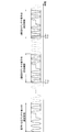
- FIG. 14 is an explanatory diagram for explaining a method of measuring the phase of a radio signal which is a millimeter wave in the information processing system according to the present embodiment.
- a radio signal in millimeter waves is transmitted from the reference antenna element, and the radio signal is taken into the vector signal analyzer 291.
- millimeter waves are generated from any of the antenna elements other than the reference antenna element (in other words, the antenna unit) (hereinafter, also referred to as “second antenna element”).
- a radio signal is transmitted, and the radio signal is captured in the vector signal analyzer 291.
- the vector signal analyzer 291 compares the millimeter-wave radio signal captured for the second antenna element with the millimeter-wave radio signal captured for the reference antenna element on the time axis.
- the phase difference T12 is calculated. That is, the phase difference T12 corresponds to the relative phase difference between the radio signal which is a millimeter wave transmitted from each of the reference antenna element and the second antenna element. Then, the calculated phase difference T12 is held as phase measurement data for the second antenna element.
- the third antenna element any other antenna element (hereinafter, also referred to as “third antenna element”) other than the reference antenna element (in other words, the antenna unit).
- the radio signal is transmitted, and the radio signal is taken into the vector signal analyzer 291.
- the vector signal analyzer 291 compares the millimeter-wave radio signal captured for the third antenna element with the millimeter-wave radio signal captured for the reference antenna element on the time axis.
- the phase difference T12 is calculated. That is, the phase difference T13 corresponds to the relative phase difference between the radio signal which is a millimeter wave transmitted from each of the reference antenna element and the third antenna element. Then, the calculated phase difference T13 is held as phase measurement data for the third antenna element.
- each antenna element (antenna unit) included in the antenna device is sequentially activated, and the phase measurement data of the radio signal which is a millimeter wave transmitted from the antenna element is acquired.
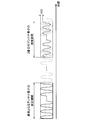
- FIG. 15 is an explanatory diagram for explaining a method of measuring the amplitude of a radio signal which is a millimeter wave in the information processing system according to the present embodiment.
- a radio signal in millimeter waves is transmitted from the reference antenna element, and the radio signal is taken into the vector signal analyzer 291.
- a radio signal which is a millimeter wave is transmitted from the second antenna element, and the radio signal is taken into the vector signal analyzer 291.
- the vector signal analyzer 291 compares the millimeter-wave radio signal captured for the second antenna element with the millimeter-wave radio signal captured for the reference antenna element to compare the amplitude (power).
- the difference A22 is calculated. That is, the amplitude difference A22 corresponds to the relative amplitude difference between the radio signal which is a millimeter wave transmitted from each of the reference antenna element and the second antenna element. Then, the calculated amplitude difference A22 is held as phase measurement data for the second antenna element.
- each antenna element included in the antenna device is sequentially activated, and measurement data of the amplitude of the radio signal which is a millimeter wave transmitted from the antenna element is acquired.
- the information processing system according to the present embodiment has a configuration as shown in FIG. 11, in which a hole is formed in the housing of the terminal device, and a cable is connected to the BB modem included in the terminal device via the hole. , It is not necessary to apply a configuration in which various signals related to the transmission of wireless signals are input from the VNA via the cable. Therefore, according to the information processing system according to the present embodiment, it is possible to construct a measurement system without requiring complicated and delicate work. Further, as described above, the terminal device 200 autonomously compensates for the frequency shift by channel estimation and frequency tracking based on the reference signal transmitted from the LTE link antenna 289. Therefore, even in a situation where a frequency shift may occur due to the influence of heat dissipation or the like due to a long measurement time, the terminal device 200 itself autonomously compensates for the frequency shift.
- the terminal device has the ability (BC Capability) to align the spatial positions of the beams with each other on the base station side and the UE (5G terminal) side as the operation of the FR2 system. Therefore, it becomes possible to realize beamforming in a more preferable manner.
- the information processing system controls the measuring instrument (for example, vector signal analyzer 291) side and the terminal device (5G terminal) side when carrying out the measurement related to the generation of the LUT. It is possible to selectively switch the method of doing so according to the situation.
- An example of a method of controlling the measuring instrument side and the UE (5G terminal) side will be described below as (Example 1) and (Example 2).
- both the measuring instrument and the terminal device may be controlled by using a dedicated test SIM.
- the control software When generating the LUT for each antenna device included in the terminal device (5G terminal), the control software is operated on both the measuring instrument and the terminal device. At this time, on the measuring instrument side, the software may be controlled from an external device (for example, a PC or the like) via IEEE 488 or Ethernet (registered trademark). Further, the terminal device side may be controlled from the external device via a cable connection using USB.
- an external device for example, a PC or the like
- IEEE 488 or Ethernet registered trademark
- the terminal device side may be controlled from the external device via a cable connection using USB.
- the above is just an example, and the method is not particularly limited as long as it is possible to control the measuring instrument side and the terminal device (5G terminal) side in time synchronization.
- a hole is made in the housing of the terminal device, a cable is connected to the BB modem provided in the terminal device via the hole, and the cable is connected. It is not necessary to apply a configuration in which various signals related to the transmission of wireless signals are input from the VNA via the VNA. From such characteristics, it is possible to construct a measurement system without requiring complicated and delicate work.
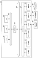
- FIG. 16 is a functional block diagram showing a configuration example of a hardware configuration of an information processing device constituting the system according to the embodiment of the present disclosure.
- the information processing device 900 constituting the system according to the present embodiment mainly includes a CPU 901, a ROM 902, and a RAM 903. Further, the information processing device 900 further includes a host bus 907, a bridge 909, an external bus 911, an interface 913, an input device 915, an output device 917, a storage device 919, a drive 921, and a connection port 923. And a communication device 925.
- the CPU 901 functions as an arithmetic processing device and a control device, and controls all or a part of the operation in the information processing device 900 according to various programs recorded in the ROM 902, the RAM 903, the storage device 919, or the removable recording medium 927.
- the ROM 902 stores programs, calculation parameters, and the like used by the CPU 901.
- the RAM 903 primary stores a program used by the CPU 901, parameters that change as appropriate in the execution of the program, and the like. These are connected to each other by a host bus 907 composed of an internal bus such as a CPU bus.
- the communication control unit 150 of the base station 100 shown in FIG. 2 and the communication control unit 240 of the terminal device 200 shown in FIG. 3 may be configured by the CPU 901. Further, various functions of the control device 295 can be realized by the operation of the CPU 901.
- the host bus 907 is connected to an external bus 911 such as a PCI (Peripheral Component Interconnect / Interface) bus via a bridge 909. Further, the input device 915, the output device 917, the storage device 919, the drive 921, the connection port 923, and the communication device 925 are connected to the external bus 911 via the interface 913.
- PCI Peripheral Component Interconnect / Interface
- the input device 915 is an operating means operated by the user, such as a mouse, keyboard, touch panel, buttons, switches, levers, and pedals. Further, the input device 915 may be, for example, a remote control means (so-called remote controller) using infrared rays or other radio waves, or an externally connected device such as a mobile phone or PDA that supports the operation of the information processing device 900. It may be 929. Further, the input device 915 is composed of, for example, an input control circuit that generates an input signal based on the information input by the user using the above-mentioned operating means and outputs the input signal to the CPU 901. By operating the input device 915, the user of the information processing device 900 can input various data to the information processing device 900 and instruct the processing operation.
- a remote control means such as a mobile phone or PDA that supports the operation of the information processing device 900. It may be 929.
- the input device 915 is composed of, for example, an input control circuit that generates an input signal
- the output device 917 is composed of a device capable of visually or audibly notifying the user of the acquired information.
- Such devices include display devices such as CRT display devices, liquid crystal display devices, plasma display devices, EL display devices and lamps, audio output devices such as speakers and headphones, and printer devices.
- the output device 917 outputs, for example, the results obtained by various processes performed by the information processing device 900.
- the display device displays the results obtained by various processes performed by the information processing device 900 as text or an image.
- the audio output device converts an audio signal composed of reproduced audio data, acoustic data, and the like into an analog signal and outputs the signal.
- the storage device 919 is a data storage device configured as an example of the storage unit of the information processing device 900.
- the storage device 919 is composed of, for example, a magnetic storage device such as an HDD (Hard Disk Drive), a semiconductor storage device, an optical storage device, an optical magnetic storage device, or the like.
- the storage device 919 stores a program executed by the CPU 901, various data, and the like.
- the storage unit 140 of the base station 100 shown in FIG. 2 and the storage unit 230 of the terminal device 200 shown in FIG. 3 may be any of the storage devices 919, ROM 902, and RAM 903, or the storage devices 919, ROM 902, and RAM 903. It may be composed of a combination of two or more of them.
- the drive 921 is a reader / writer for a recording medium, and is built in or externally attached to the information processing device 900.
- the drive 921 reads the information recorded on the removable recording medium 927 such as the mounted magnetic disk, optical disk, magneto-optical disk, or semiconductor memory, and outputs the information to the RAM 903.
- the drive 921 can also write a record on a removable recording medium 927 such as a mounted magnetic disk, optical disk, magneto-optical disk, or semiconductor memory.
- the removable recording medium 927 is, for example, DVD media, HD-DVD media, Blu-ray (registered trademark) media, or the like.
- the removable recording medium 927 may be a compact flash (registered trademark) (CF: CompactFlash), a flash memory, an SD memory card (Secure Digital memory card), or the like. Further, the removable recording medium 927 may be, for example, an IC card (Integrated Circuit card) or an electronic device equipped with a non-contact type IC chip.
- CF CompactFlash
- SD memory card Secure Digital memory card
- the connection port 923 is a port for directly connecting to the information processing device 900.
- the connection port 923 there are a USB (Universal Serial Bus) port, an IEEE1394 port, a SCSI (Small Computer System Interface) port, and the like.
- Another example of the connection port 923 is an RS-232C port, an optical audio terminal, an HDMI (registered trademark) (High-Definition Multimedia Interface) port, and the like.
- the communication device 925 is, for example, a communication interface composed of a communication device or the like for connecting to a communication network (network) 931.
- the communication device 925 is, for example, a communication card for a wired or wireless LAN (Local Area Network), Bluetooth (registered trademark), WUSB (Wireless USB), or the like.
- the communication device 925 may be a router for optical communication, a router for ADSL (Asymmetric Digital Subscriber Line), a modem for various communications, or the like.
- the communication device 925 can transmit and receive signals and the like to and from the Internet and other communication devices in accordance with a predetermined protocol such as TCP / IP.
- the communication network 931 connected to the communication device 925 is composed of a network connected by wire or wireless, and may be, for example, the Internet, a home LAN, infrared communication, radio wave communication, satellite communication, or the like. ..
- the wireless communication unit 120 and the network communication unit 130 of the base station 100 shown in FIG. 2, and the wireless communication unit 220 of the terminal device 200 shown in FIG. 3 may be configured by the communication device 925.
- the above is an example of a hardware configuration capable of realizing the functions of the information processing device 900 constituting the system according to the embodiment of the present disclosure.
- Each of the above-mentioned components may be configured by using general-purpose members, or may be configured by hardware specialized for the function of each component. Therefore, it is possible to appropriately change the hardware configuration to be used according to the technical level at each time when the present embodiment is implemented.
- various configurations corresponding to the information processing apparatus 900 constituting the system are naturally provided.
- the recording medium is, for example, a magnetic disk, an optical disk, a magneto-optical disk, a flash memory, or the like.
- the above computer program may be distributed via a network, for example, without using a recording medium.
- the number of computers for executing the computer program is not particularly limited. For example, a plurality of computers (for example, a plurality of servers, etc.) may execute the computer program in cooperation with each other.
- Application example 1 Application example to other communication devices> First, as an application example 1, an example in which the technology according to the present disclosure is applied to a device other than a communication terminal such as a smartphone will be described.
- IoT Internet of Things
- FIG. 17 is an explanatory diagram for explaining an application example of the communication device according to the present embodiment, and shows an example when the technique according to the present disclosure is applied to a camera device.
- the outer surfaces of the housing of the camera device 300 are located in the vicinity of the surfaces 301 and 302 facing in different directions.
- the antenna device is held.
- reference numeral 311 schematically shows an antenna device according to an embodiment of the present disclosure.
- the camera device 300 shown in FIG. 17 can transmit or receive, for example, a radio signal propagating in a direction substantially matching the normal direction of the surfaces 301 and 302, respectively. ..
- the antenna device 311 may be provided not only on the surfaces 301 and 302 shown in FIG. 17 but also on other surfaces.
- communication with another device using a directional beam is controlled according to a change in the posture of the camera device 300 based on the above-described technology according to the present disclosure. By doing so, it becomes possible to realize communication using millimeter waves in a more preferable manner.
- FIG. 18 is an explanatory diagram for explaining an application example of the communication device according to the present embodiment, and shows an example in the case where the technique according to the present disclosure is applied to a camera device installed under the drone. ing.
- the radio signal millimeter wave
- FIG. 18 one implementation of the present disclosure is made so that the outer surface 401 of the housing of the camera device 400 installed at the lower part of the drone is located in the vicinity of each portion facing different directions.
- the antenna device according to the form is held.
- reference numeral 411 schematically shows an antenna device according to an embodiment of the present disclosure.
- an antenna device 411 may be provided in each part of the housing of the drone itself. Even in this case, it is particularly preferable that the antenna device 411 is provided on the lower side of the housing.
- each partial region in the curved surface is formed.
- the antenna device 411 is held in the vicinity of each of the plurality of partial regions whose normal directions intersect with each other or whose normal directions are twisted with each other.
- the camera device 400 shown in FIG. 18 can transmit or receive a radio signal propagating in a direction substantially coincide with the normal direction of each partial region.
- the examples described with reference to FIGS. 17 and 18 are merely examples, and the application destination of the technology according to the present disclosure is not particularly limited as long as it is a device that performs communication using millimeter waves.
- the business areas newly added in 5G are diverse, such as the automobile field, industrial equipment field, home security field, smart meter field, and other IoT fields, and for communication terminals applied in each field. It is possible to apply the technology according to the present disclosure.
- application destinations of the technology according to the present disclosure include head-mounted wearable devices used for realizing AR and VR, and various wearable devices used in telemedicine and the like. ..
- the technology according to the present disclosure can be applied to a so-called portable game device, a camcorder for a broadcasting station, or the like if wireless communication is possible. ..
- various so-called autonomous robots such as customer service robots, pet-type robots, and work robots have been proposed, and even such robots may have a communication function.
- the technology according to the present disclosure can be applied.
- the technique according to the present disclosure may be applied not only to the drone described above but also to various moving objects such as automobiles, motorcycles, bicycles and the like.
- Application example 2 Application example to communication based on other communication standards> Subsequently, as application example 2, an example in which the technology according to the present disclosure is applied to communication other than communication using millimeter waves in 5G, in particular, application to communication based on other communication standards. The explanation will be focused on.
- wireless communications based on the Wi-Fi (registered trademark) standard communications based on the IEEE802.11ad standard that uses the 60 GHz band, communications based on the IEEE802.11ay standard for which standardization work is underway, etc. It is possible to apply the technology according to the present disclosure to.
- the beamforming procedure in the IEEE802.11ad standard is mainly divided into two stages, SLS (Sector Level Sweep) and BRP (Beam Refinement Protocol).
- the SLS searches for a communication partner and starts communication.
- the maximum number of sectors is defined as 64 for one ANT and 128 for the total of all ANTs.
- BRP is appropriately carried out after the end of SLS, for example, after the ring is broken.
- BPL is established by the wide beam in the operation based on the IA procedure in the communication using millimeter waves in 5G, and the narrow beam is operated by the operation of BR (Beam Refinement) in BM (Beam Management) in the CONNECTED mode. It is similar to the mechanism by which BPL is established.
- the IEEE802.11ay standard is currently under development, but the data rate is based on a combination of channel bonding technology and higher-order modulation, similar to the "contiguous" "intra-CA” in 5G millimeter-wave communication. Speeding up is being considered.
- the information processing device includes a generation unit that generates control information for controlling the directivity of a radio signal transmitted from an antenna device including a plurality of antenna elements. Be prepared.
- the generation unit receives the first information according to the phase measurement result of the radio signal transmitted from the first antenna element among the plurality of antenna elements, and the radio signal transmitted from the first antenna element.
- the phase, the phase of the radio signal transmitted from the second antenna element different from the first antenna element, and the second information according to the measurement result of the relative deviation between the phases are acquired.
- the generation unit generates the control information based on the first information and the second information.
- the terminal device is a control that controls the directivity of a radio signal transmitted from the antenna device based on the antenna device including a plurality of antenna elements and the control information generated in advance. It has a part and.
- the following configurations also belong to the technical scope of the present disclosure.
- a generator that generates control information for controlling the directivity of a radio signal transmitted from an antenna device including a plurality of antenna elements.
- the generator The first information according to the phase measurement result of the radio signal transmitted from the first antenna element among the plurality of antenna elements, and Measurement result of relative deviation between the phase of the radio signal transmitted from the first antenna element and the phase of the radio signal transmitted from the second antenna element different from the first antenna element.
- the second information according to To get The control information is generated based on the first information and the second information.
- Information processing device (2)
- the first information includes information according to the measurement result of the amplitude of the radio signal transmitted from the first antenna element.
- the second information is based on the measurement result of the relative deviation between the amplitude of the radio signal transmitted from the first antenna element and the amplitude of the radio signal transmitted from the second antenna element. Including the corresponding information, The information processing device according to (1) above. (3) The information processing device according to (1) or (2), wherein the control information is generated based on the first information and the second information acquired for each posture of the antenna device. (4) The generation unit recognizes the timing at which the terminal device transmits the wireless signal to the antenna device based on the information notified from the communication device configured to be able to communicate with the terminal device including the antenna device. The information processing apparatus according to any one of 1) to (3).
- a terminal device including an antenna device including a plurality of antenna elements, An information processing device in which the antenna device generates control information for controlling the directivity of a wireless signal.
- the information processing device The first information according to the phase measurement result of the radio signal transmitted from the first antenna element among the plurality of antenna elements, and Measurement result of relative deviation between the phase of the radio signal transmitted from the first antenna element and the phase of the radio signal transmitted from the second antenna element different from the first antenna element.
- the second information according to To get The control information is generated based on the first information and the second information.
- Information processing system (6)
- the first information includes information according to the measurement result of the amplitude of the radio signal transmitted from the first antenna element.
- the second information is based on the measurement result of the relative deviation between the amplitude of the radio signal transmitted from the first antenna element and the amplitude of the radio signal transmitted from the second antenna element. Including the corresponding information, The information processing system according to (5) above. (7) A communication device for wirelessly communicating with the terminal device using a frequency band different from the frequency band in which the wireless signal is transmitted is provided. The terminal device controls the transmission of the radio signal based on the control signal transmitted from the communication device. The information processing system according to (5) or (6) above. (8) The information processing system according to (7) above, wherein the terminal device corrects a frequency shift of the radio signal based on the control signal.
- the communication device transmits a control signal to the terminal device, notifies the information processing device of information about the control signal, and causes the information processing device.
- the terminal device controls the transmission timing of the radio signal based on the control signal.
- the information processing device recognizes the transmission timing based on the information regarding the control signal.
- the information processing system according to (7) or (8) above.
- a posture control device for controlling the posture of the terminal device is provided.
- the control information is generated based on the first information and the second information acquired for each posture of the antenna device according to the posture of the terminal device.
- the information processing system according to any one of (5) to (9) above.
- the terminal device includes a plurality of the antenna devices.
- the control information is generated based on the first information and the second information acquired for each of the plurality of antenna devices.
- the information processing system according to any one of (5) to (10) above.
- An antenna device that includes multiple antenna elements and A control unit that controls the directivity of the radio signal transmitted from the antenna device based on the control information generated in advance.
- the control information is The first information according to the phase measurement result of the radio signal transmitted from the first antenna element among the plurality of antenna elements, and Measurement result of relative deviation between the phase of the radio signal transmitted from the first antenna element and the phase of the radio signal transmitted from the second antenna element different from the first antenna element.
- the second information according to Generated based on Terminal equipment.
- the first information includes information according to the measurement result of the amplitude of the radio signal transmitted from the first antenna element.
- the second information is based on the measurement result of the relative deviation between the amplitude of the radio signal transmitted from the first antenna element and the amplitude of the radio signal transmitted from the second antenna element. Including the corresponding information, The terminal device according to (12) above. (14) The computer The first information according to the phase measurement result of the radio signal transmitted from the first antenna element among the plurality of antenna elements included in the antenna device, and Measurement result of relative deviation between the phase of the radio signal transmitted from the first antenna element and the phase of the radio signal transmitted from the second antenna element different from the first antenna element. The second information according to To get and To generate control information for controlling the directivity of the radio signal transmitted from the antenna device based on the first information and the second information. Information processing methods, including.
- Terminal device 210 Antenna unit 220 Wireless communication unit 230 Storage unit 230 Detection unit 240 Communication control unit 250 Antenna device 251 Mixer 253 RF distributor (synthesis) device 255 Antenna unit 257 Phase device 259a, 259b Switch 261 Amplifier 263 Amplifier 265 Antenna element 281 Attitude control device 283 Position controller 285 Reflector 287 Feed antenna 289 Link antenna for LTE 291 Vector signal analyzer 293 System simulator for LTE 295 Control device
Landscapes
- Engineering & Computer Science (AREA)
- Computer Networks & Wireless Communication (AREA)
- Signal Processing (AREA)
- Mobile Radio Communication Systems (AREA)
- Radio Transmission System (AREA)
Priority Applications (5)
| Application Number | Priority Date | Filing Date | Title |
|---|---|---|---|
| EP19925318.8A EP3952122A4 (en) | 2019-04-17 | 2019-04-17 | INFORMATION PROCESSING DEVICE, INFORMATION PROCESSING SYSTEM, TERMINAL DEVICE AND INFORMATION PROCESSING METHOD |
| PCT/JP2019/016506 WO2020213093A1 (ja) | 2019-04-17 | 2019-04-17 | 情報処理装置、情報処理システム、端末装置、及び情報処理方法 |
| JP2021514716A JPWO2020213093A1 (https=) | 2019-04-17 | 2019-04-17 | |
| US17/598,882 US20220190885A1 (en) | 2019-04-17 | 2019-04-17 | Information processing device, information processing system, terminal device, and information processing method |
| CN201980095251.3A CN113647025A (zh) | 2019-04-17 | 2019-04-17 | 信息处理设备、信息处理系统、终端设备和信息处理方法 |
Applications Claiming Priority (1)
| Application Number | Priority Date | Filing Date | Title |
|---|---|---|---|
| PCT/JP2019/016506 WO2020213093A1 (ja) | 2019-04-17 | 2019-04-17 | 情報処理装置、情報処理システム、端末装置、及び情報処理方法 |
Publications (1)
| Publication Number | Publication Date |
|---|---|
| WO2020213093A1 true WO2020213093A1 (ja) | 2020-10-22 |
Family
ID=72838102
Family Applications (1)
| Application Number | Title | Priority Date | Filing Date |
|---|---|---|---|
| PCT/JP2019/016506 Ceased WO2020213093A1 (ja) | 2019-04-17 | 2019-04-17 | 情報処理装置、情報処理システム、端末装置、及び情報処理方法 |
Country Status (5)
| Country | Link |
|---|---|
| US (1) | US20220190885A1 (https=) |
| EP (1) | EP3952122A4 (https=) |
| JP (1) | JPWO2020213093A1 (https=) |
| CN (1) | CN113647025A (https=) |
| WO (1) | WO2020213093A1 (https=) |
Cited By (1)
| Publication number | Priority date | Publication date | Assignee | Title |
|---|---|---|---|---|
| WO2023090517A1 (ko) * | 2021-11-19 | 2023-05-25 | 대한민국(과학기술정보통신부 국립전파연구원장) | 방송통신기자재 성능 측정 시스템 및 그 방법 |
Families Citing this family (6)
| Publication number | Priority date | Publication date | Assignee | Title |
|---|---|---|---|---|
| DE102019131374A1 (de) * | 2019-11-20 | 2021-05-20 | Rohde & Schwarz GmbH & Co. Kommanditgesellschaft | Messgerät und Messverfahren zur Bestimmung einer gesamten Strahlungsleistung |
| US11044693B1 (en) * | 2020-05-08 | 2021-06-22 | Qualcomm Incorporated | Efficient positioning enhancement for dynamic spectrum sharing |
| CN117256107A (zh) * | 2021-05-06 | 2023-12-19 | 高通股份有限公司 | 用于基于窄波束的信道接入的散度统计办法 |
| US11509381B2 (en) * | 2021-11-12 | 2022-11-22 | Ultralogic 6G, Llc | Resource-efficient beam selection in 5G and 6G |
| US12395213B2 (en) * | 2022-08-11 | 2025-08-19 | Samsung Electronics Co., Ltd. | Circular antenna array design for future 6G TBPS wireless communications |
| CN116929289B (zh) * | 2023-09-18 | 2024-01-05 | 中国科学院西安光学精密机械研究所 | 一种天线姿态快速测量系统及方法 |
Citations (4)
| Publication number | Priority date | Publication date | Assignee | Title |
|---|---|---|---|---|
| WO2008139832A1 (ja) * | 2007-05-07 | 2008-11-20 | Murata Manufacturing Co., Ltd. | 放射効率測定装置および放射効率測定方法 |
| JP2012124749A (ja) * | 2010-12-09 | 2012-06-28 | Denso Corp | フェーズドアレイアンテナの位相校正方法及びフェーズドアレイアンテナ |
| JP2017187406A (ja) * | 2016-04-07 | 2017-10-12 | アンリツ株式会社 | 位相調整システム及び位相調整方法 |
| JP2019057850A (ja) * | 2017-09-22 | 2019-04-11 | Necスペーステクノロジー株式会社 | フェーズドアレーアンテナ、デジタル無線中継器、およびフェーズドアレーアンテナの素子間偏差測定方法 |
Family Cites Families (3)
| Publication number | Priority date | Publication date | Assignee | Title |
|---|---|---|---|---|
| US6507315B2 (en) * | 2001-05-03 | 2003-01-14 | Lockheed Martin Corporation | System and method for efficiently characterizing the elements in an array antenna |
| EP1770827B1 (en) * | 2005-09-28 | 2008-05-28 | Alcatel Lucent | Calibration method for smart antenna arrays |
| KR100776679B1 (ko) * | 2006-09-27 | 2007-11-16 | 한국전자통신연구원 | 챔버의 비운용 주파수 대역에서의 안테나 특성 측정 방법 |
-
2019
- 2019-04-17 JP JP2021514716A patent/JPWO2020213093A1/ja active Pending
- 2019-04-17 WO PCT/JP2019/016506 patent/WO2020213093A1/ja not_active Ceased
- 2019-04-17 CN CN201980095251.3A patent/CN113647025A/zh not_active Withdrawn
- 2019-04-17 EP EP19925318.8A patent/EP3952122A4/en not_active Withdrawn
- 2019-04-17 US US17/598,882 patent/US20220190885A1/en not_active Abandoned
Patent Citations (4)
| Publication number | Priority date | Publication date | Assignee | Title |
|---|---|---|---|---|
| WO2008139832A1 (ja) * | 2007-05-07 | 2008-11-20 | Murata Manufacturing Co., Ltd. | 放射効率測定装置および放射効率測定方法 |
| JP2012124749A (ja) * | 2010-12-09 | 2012-06-28 | Denso Corp | フェーズドアレイアンテナの位相校正方法及びフェーズドアレイアンテナ |
| JP2017187406A (ja) * | 2016-04-07 | 2017-10-12 | アンリツ株式会社 | 位相調整システム及び位相調整方法 |
| JP2019057850A (ja) * | 2017-09-22 | 2019-04-11 | Necスペーステクノロジー株式会社 | フェーズドアレーアンテナ、デジタル無線中継器、およびフェーズドアレーアンテナの素子間偏差測定方法 |
Non-Patent Citations (4)
| Title |
|---|
| 3GPP TR38.810 |
| ERICSSON, MVG INDUSTRIES, KATHREIN,: "TP to TR 37.842: On Test Methods", 3GPP TSG-RAN WG4#78BIS R4-162966, 26 April 2016 (2016-04-26), XP051094348, Retrieved from the Internet <URL:http://www.3gpp.org/ftp/tsg_ran/WG4_Radio/TSGR4_78Bis/Docs/R4-162966.zip> [retrieved on 20160807] * |
| SATOSHI SUYAMA ET AL.: "5G Multi-Antenna Technology", NTT DOCOMO TECHNICAL JOURNAL, vol. 23, no. 4, 2016, pages 30 - 39 |
| See also references of EP3952122A4 |
Cited By (4)
| Publication number | Priority date | Publication date | Assignee | Title |
|---|---|---|---|---|
| WO2023090517A1 (ko) * | 2021-11-19 | 2023-05-25 | 대한민국(과학기술정보통신부 국립전파연구원장) | 방송통신기자재 성능 측정 시스템 및 그 방법 |
| JP2024536730A (ja) * | 2021-11-19 | 2024-10-08 | ナショナル ラジオ リサーチ エージェンシー | 放送通信機器性能測定システム及びその方法 |
| JP7752756B2 (ja) | 2021-11-19 | 2025-10-10 | ナショナル ラジオ リサーチ エージェンシー | 放送通信機器性能測定システム及びその方法 |
| US12449460B2 (en) | 2021-11-19 | 2025-10-21 | National Radio Research Agency | System for measuring performance of equipment under test, and method therefor |
Also Published As
| Publication number | Publication date |
|---|---|
| CN113647025A (zh) | 2021-11-12 |
| EP3952122A4 (en) | 2022-04-20 |
| JPWO2020213093A1 (https=) | 2020-10-22 |
| US20220190885A1 (en) | 2022-06-16 |
| EP3952122A1 (en) | 2022-02-09 |
Similar Documents
| Publication | Publication Date | Title |
|---|---|---|
| WO2020213093A1 (ja) | 情報処理装置、情報処理システム、端末装置、及び情報処理方法 | |
| CN109845128B (zh) | 促进来自交通工具用户设备的波束成形的系统和方法 | |
| WO2021084592A1 (ja) | 情報処理装置、通信装置、情報処理方法、通信方法、情報処理プログラム、及び通信プログラム | |
| CN115812159A (zh) | 通过使用自适应相变设备来确定用户设备的位置 | |
| US20240405807A1 (en) | Systems and methods for beam spot alignment on reconfigurable intelligent surface in communication systems | |
| US12191971B2 (en) | Electronic device, wireless communication method and computer-readable storage medium | |
| Rajagopal et al. | Self-interference mitigation for in-band mmWave wireless backhaul | |
| Rebato et al. | Multi-sector and multi-panel performance in 5G mmWave cellular networks | |
| WO2023115058A2 (en) | Adaptive phase-changing devices for active coordination sets | |
| EP3716497A1 (en) | Electronic device and method for wireless communication system, and storage medium | |
| US20250158693A1 (en) | mmWAVE 5G PROPAGATION USING INTER-SECTOR BEAMSETS | |
| JP2025501933A (ja) | 適応型相変化デバイスを使用した多重入出力伝送 | |
| WO2022187801A1 (en) | Phase vector training for adaptive phase-changing device-enabled communication | |
| US12598579B2 (en) | Collaborative geolocation of an access point | |
| EP3668143B1 (en) | Communication device and communication method | |
| Saha et al. | 60 GHz indoor WLANs: Insights into performance and power consumption | |
| US12615540B2 (en) | Electronic device, method and storage medium for wireless communication system | |
| Haider et al. | itrack: Tracking indicator leds on aps to bootstrap mmwave beam acquisition and steering | |
| JP7781288B2 (ja) | スマートリピータのための方法および装置 | |
| EP3089515A1 (en) | Apparatuses, methods and computer programs for a mobility management unit of a first and a second mobile communication system and a mobile transceiver | |
| US12362809B2 (en) | User equipment (UE) antenna module lock function | |
| Baba et al. | Trends in 5G NR mmWave UE RF Conformance Test Standards | |
| WO2024174237A1 (en) | Devices, methods, and apparatuses for joint communication and sensing | |
| US20250202567A1 (en) | Conformance testing for a user equipment under blockage conditions | |
| US20250062815A1 (en) | Ue-side beam selection procedure |
Legal Events
| Date | Code | Title | Description |
|---|---|---|---|
| 121 | Ep: the epo has been informed by wipo that ep was designated in this application |
Ref document number: 19925318 Country of ref document: EP Kind code of ref document: A1 |
|
| ENP | Entry into the national phase |
Ref document number: 2021514716 Country of ref document: JP Kind code of ref document: A |
|
| NENP | Non-entry into the national phase |
Ref country code: DE |
|
| ENP | Entry into the national phase |
Ref document number: 2019925318 Country of ref document: EP Effective date: 20211101 |