WO2020209337A1 - 識別装置、識別方法、識別処理プログラム、生成装置、生成方法、および生成処理プログラム - Google Patents
識別装置、識別方法、識別処理プログラム、生成装置、生成方法、および生成処理プログラム Download PDFInfo
- Publication number
- WO2020209337A1 WO2020209337A1 PCT/JP2020/015984 JP2020015984W WO2020209337A1 WO 2020209337 A1 WO2020209337 A1 WO 2020209337A1 JP 2020015984 W JP2020015984 W JP 2020015984W WO 2020209337 A1 WO2020209337 A1 WO 2020209337A1
- Authority
- WO
- WIPO (PCT)
- Prior art keywords
- vibration
- identified
- dimensional object
- feature amount
- identification
- Prior art date
- Legal status (The legal status is an assumption and is not a legal conclusion. Google has not performed a legal analysis and makes no representation as to the accuracy of the status listed.)
- Ceased
Links
Images







Classifications
-
- G—PHYSICS
- G01—MEASURING; TESTING
- G01N—INVESTIGATING OR ANALYSING MATERIALS BY DETERMINING THEIR CHEMICAL OR PHYSICAL PROPERTIES
- G01N29/00—Investigating or analysing materials by the use of ultrasonic, sonic or infrasonic waves; Visualisation of the interior of objects by transmitting ultrasonic or sonic waves through the object
- G01N29/04—Analysing solids
- G01N29/12—Analysing solids by measuring frequency or resonance of acoustic waves
-
- G—PHYSICS
- G01—MEASURING; TESTING
- G01N—INVESTIGATING OR ANALYSING MATERIALS BY DETERMINING THEIR CHEMICAL OR PHYSICAL PROPERTIES
- G01N29/00—Investigating or analysing materials by the use of ultrasonic, sonic or infrasonic waves; Visualisation of the interior of objects by transmitting ultrasonic or sonic waves through the object
- G01N29/44—Processing the detected response signal, e.g. electronic circuits specially adapted therefor
- G01N29/4409—Processing the detected response signal, e.g. electronic circuits specially adapted therefor by comparison
- G01N29/4418—Processing the detected response signal, e.g. electronic circuits specially adapted therefor by comparison with a model, e.g. best-fit, regression analysis
-
- G—PHYSICS
- G01—MEASURING; TESTING
- G01N—INVESTIGATING OR ANALYSING MATERIALS BY DETERMINING THEIR CHEMICAL OR PHYSICAL PROPERTIES
- G01N29/00—Investigating or analysing materials by the use of ultrasonic, sonic or infrasonic waves; Visualisation of the interior of objects by transmitting ultrasonic or sonic waves through the object
- G01N29/22—Details, e.g. general constructional or apparatus details
- G01N29/24—Probes
- G01N29/2437—Piezoelectric probes
-
- G—PHYSICS
- G01—MEASURING; TESTING
- G01N—INVESTIGATING OR ANALYSING MATERIALS BY DETERMINING THEIR CHEMICAL OR PHYSICAL PROPERTIES
- G01N29/00—Investigating or analysing materials by the use of ultrasonic, sonic or infrasonic waves; Visualisation of the interior of objects by transmitting ultrasonic or sonic waves through the object
- G01N29/34—Generating the ultrasonic, sonic or infrasonic waves, e.g. electronic circuits specially adapted therefor
- G01N29/348—Generating the ultrasonic, sonic or infrasonic waves, e.g. electronic circuits specially adapted therefor with frequency characteristics, e.g. single frequency signals, chirp signals
-
- G—PHYSICS
- G01—MEASURING; TESTING
- G01N—INVESTIGATING OR ANALYSING MATERIALS BY DETERMINING THEIR CHEMICAL OR PHYSICAL PROPERTIES
- G01N29/00—Investigating or analysing materials by the use of ultrasonic, sonic or infrasonic waves; Visualisation of the interior of objects by transmitting ultrasonic or sonic waves through the object
- G01N29/44—Processing the detected response signal, e.g. electronic circuits specially adapted therefor
- G01N29/46—Processing the detected response signal, e.g. electronic circuits specially adapted therefor by spectral analysis, e.g. Fourier analysis or wavelet analysis
-
- G—PHYSICS
- G01—MEASURING; TESTING
- G01V—GEOPHYSICS; GRAVITATIONAL MEASUREMENTS; DETECTING MASSES OR OBJECTS; TAGS
- G01V1/00—Seismology; Seismic or acoustic prospecting or detecting
-
- G—PHYSICS
- G01—MEASURING; TESTING
- G01N—INVESTIGATING OR ANALYSING MATERIALS BY DETERMINING THEIR CHEMICAL OR PHYSICAL PROPERTIES
- G01N2291/00—Indexing codes associated with group G01N29/00
- G01N2291/02—Indexing codes associated with the analysed material
- G01N2291/023—Solids
-
- G—PHYSICS
- G01—MEASURING; TESTING
- G01N—INVESTIGATING OR ANALYSING MATERIALS BY DETERMINING THEIR CHEMICAL OR PHYSICAL PROPERTIES
- G01N2291/00—Indexing codes associated with group G01N29/00
- G01N2291/02—Indexing codes associated with the analysed material
- G01N2291/024—Mixtures
-
- G—PHYSICS
- G01—MEASURING; TESTING
- G01N—INVESTIGATING OR ANALYSING MATERIALS BY DETERMINING THEIR CHEMICAL OR PHYSICAL PROPERTIES
- G01N2291/00—Indexing codes associated with group G01N29/00
- G01N2291/26—Scanned objects
- G01N2291/269—Various geometry objects
- G01N2291/2698—Other discrete objects, e.g. bricks
Definitions
- An embodiment of the present invention relates to an identification device, an identification method, an identification processing program, a generation device, a generation method, and a generation processing program.
- Non-Patent Document 1 In a state where a cavity is provided inside a 3D printed object, the presence or absence of a cavity is distinguished by distinguishing between a portion where the cavity exists and a portion where the cavity does not exist by utilizing the difference in light reflection characteristics. There is a method of recovering information from (see, for example, Non-Patent Document 1).
- Non-Patent Document 2 there is also an information embedding and identification method that utilizes the way the sound reverberates in the cavity provided inside the object (see, for example, Non-Patent Document 2).
- this method utilizes the difference in light reflection characteristics, it is necessary to use a translucent material that transmits light to print the object in 3D, and an opaque material that does not transmit light or light.
- the applicable print material is restricted, such as not being applicable to 3D-printed objects using a metal material that reflects light.
- the object needs to be provided with at least two openings, which limits the applicable object structure.
- the present invention has been made in view of the above circumstances, and an object of the present invention is an identification device, an identification method, an identification processing program, a generation device, and a generation method capable of appropriately identifying a three-dimensional object. , And to provide a generation processing program.
- one aspect of the identification device is to generate a first vibration given to a three-dimensional object to be identified by a vibration generator having an integrated structure.
- the feature amount generation unit that generates the feature amount indicating the frequency characteristic of the second vibration and the frequency characteristic based on the vibration propagated inside the identified three-dimensional object are shown.
- the feature amount stored in the storage device in which the feature amount is stored, and the identification unit for identifying the three-dimensional object to be identified based on the feature amount generated by the feature amount generation unit are provided.
- One aspect of the identification method is an identification method performed by an identification device, which generates a first vibration given to a three-dimensional object to be identified, which has an integrated structure. It is generated by a device, and among the first vibrations given to the three-dimensional object, the detection signal corresponding to the second vibration propagating inside the three-dimensional object is acquired from the vibration detector. Based on the acquired detection signal, a feature amount indicating the frequency characteristic of the second vibration is generated, and a feature amount indicating the frequency characteristic based on the vibration propagating inside the identified three-dimensional object is generated. The feature amount stored in the stored storage device and the three-dimensional object to be identified are identified based on the generated feature amount.
- one aspect of the generator according to the embodiment of the present invention is the shape of the vibration generator that generates the first vibration given to the three-dimensional object to be identified, and the three-dimensional object. Based on the shape of the vibration detector that detects the second vibration propagating inside the three-dimensional object among the given first vibrations, it has a contact surface suitable for propagating the second vibration. It is provided with a generation unit that generates a model of a three-dimensional object to be identified.
- One aspect of the generation method according to the embodiment of the present invention is the generation method performed by the generation device, the shape of the vibration generator that generates the first vibration given to the three-dimensional object to be identified, and the above-mentioned.
- a contact surface suitable for propagating the second vibration based on the shape of the vibration detector that detects the second vibration propagating inside the three-dimensional object among the first vibrations given to the three-dimensional object.
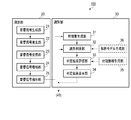
- FIG. 1 is a diagram showing an application example of the object identification device according to the embodiment of the present invention.
- FIG. 2 is a block diagram showing an example of functional configuration of a measuring unit and an identification unit of an object identification device according to an embodiment of the present invention.
- FIG. 3 is a diagram showing an example of the object to be identified.
- FIG. 4 is a diagram showing an example of the object to be identified.
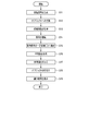
- FIG. 5 is a flow chart showing an example of a procedure for identification by the identification device according to the first embodiment of the present invention.
- FIG. 6 is a flowchart showing an example of a procedure for identification by the identification device according to the second embodiment of the present invention.
- FIG. 7 is a flowchart showing an example of a procedure for identification by the identification device according to the third embodiment of the present invention.
- FIG. 8 is a flowchart showing an example of a procedure for identification by the identification device according to the fourth embodiment of the present invention.
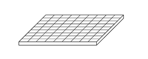
- FIG. 9 is a diagram showing an example of the appearance of the measuring device.
- FIG. 10 is a diagram showing an example of the appearance of the vibration generator.
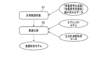
- FIG. 11 is a diagram showing an example of the functional configuration of the object model (model) generator according to the sixth embodiment of the present invention.
- FIG. 12 is a flowchart showing an example of a procedure related to object model generation by the object model generation device according to the sixth embodiment of the present invention.
- FIG. 13 is a block diagram showing an example of a hardware configuration of the object identification device according to the embodiment of the present invention.
- the identification device analyzes an acoustic spectrum (spectrum) obtained by analyzing vibration propagating inside an object, and identifies an object based on the difference in the acoustic spectrum.
- This identification device analyzes the resonance characteristics that change depending on the shape, material, boundary conditions, etc. from the acoustic spectrum, and identifies the object based on the difference in the spectrum.
- any medium in which vibration propagates can be applied as an object to be identified regardless of the filling rate.
- any material having a low sound wave attenuation rate can be applied as an object to be identified, and it is not necessary to provide an opening in this object.
- the object to be identified is a certain object A, but also data of all objects to be identified that can be arbitrarily selected are used for classification. Generate an object identification model that is a model. Therefore, according to this difference, it is possible to distinguish which object the object to be identified is, for example, the target A, the target B, and the target C, respectively.
- the identification device can perform not only authenticity determination but also object identification at the same time. Further, the identification device can identify an object from the acoustic spectrum by associating the acoustic spectrum with an object ID (identification) unique to each object. Further, by preparing a plurality of measurement portions or devising the shape of the measurement portion and the shape of the object, the identification accuracy by the identification device can be improved.
- FIG. 1 is a diagram showing an application example of the object identification device according to the embodiment of the present invention.
- the object identification device 100 according to the embodiment of the present invention can be configured as a computer provided with a central processing unit (CPU), a program memory, a calculation memory, and the like.
- the object identification device 100 includes a measurement unit 20, an identification unit 30, and a database. ) 40.
- the measuring unit 20 is a resonance characteristic acquisition unit.
- FIG. 2 is a block diagram showing a functional configuration example of the measurement unit and the identification unit of the object identification device according to the embodiment of the present invention.
- the measuring unit 20 includes an acoustic signal generation unit 21, an acoustic signal generation unit 22, an acoustic signal reception unit 23, an acoustic signal amplification unit 24, and an acoustic signal extraction unit 25.
- the identification unit 30 includes a feature amount generation unit 31, an identification determination unit 32, a determination result evaluation unit 33, and a determination result display unit 34.
- the identification unit 30 can include an accompanying information citation unit 35 and an analysis model generation unit 36. The functions of the accompanying information quoting unit 35 and the analysis model generation unit 36 will be described later.
- Each part in the object identification device 100 can be realized by causing the CPU to execute a program stored in the program memory.
- the object identification device 100 may be configured by hardware, but after a program having the procedure shown in the flowchart described later is installed on a well-known computer via a medium or a communication line, the object identification device 100 is installed. It can also be realized by a combination of a computer and a database 40, a computer having a database 40, or the like.
- FIG. 3 and 4 are diagrams showing an example of the object to be identified.
- seven objects (a, b, c, d, e, f and g in FIG. 3) are shown respectively, and as a whole, an integrated structure inside the object is shown.
- the vibration generator connected to the acoustic signal generating unit 22 and the vibration detector connected to the acoustic signal receiving unit 23 are brought into contact with the target object, the object is subjected to the contact.
- An object having an integrated structure inside the object between two points can be applied as an object to be identified regardless of the filling rate of the internal structure of the object, unlike the prior art.
- a translucent material and a metal material can also be applied as objects to be identified.
- the vibration generator and vibration detector described above can be realized by a piezoelectric element that does not contact each other, for example, a piezoelectric element. Further, this piezoelectric element can be used as an element for a vibration generator and an element for a vibration detector.
- the measuring unit 20 generates an acoustic signal having an arbitrary frequency characteristic of the ultrasonic band, gives the vibration of the ultrasonic band to the object to be identified from the piezoelectric element, and then acquires the vibration that has passed through this object. ..
- the identification unit 30 identifies the object to be identified based on the vibration signal data acquired by the measurement unit 20, and presents the identification result.
- the acoustic signal generation unit 21 generates an acoustic signal that is a source of vibration generated by the acoustic signal generation unit 22.
- the acoustic signal generation unit 22 generates a vibration having the same frequency characteristics as the acoustic signal generated by the acoustic signal generation unit 21 by a vibration generator that comes into contact with the object to be identified, and causes this vibration to be generated in the object to be identified. give.
- the acoustic signal receiving unit 23 detects the vibration of the object to be identified by the vibration generated by the acoustic signal generating unit 22 by the vibration detector in contact with the object to be identified. The signal indicated by this vibration is received.
- the sound signal generation unit 22 and the sound signal reception unit 23 can be realized by an audio interface.
- the acoustic signal amplification unit 24 obtains a signal from the vibration received by the acoustic signal reception unit 23 and amplifies this signal.
- the acoustic signal extraction unit 25 extracts the signal amplified by the acoustic signal amplification unit 24 at regular intervals on the time axis.
- the feature amount generation unit 31 generates a feature amount for identifying the object to be identified based on the waveform of the signal extracted by the acoustic signal extraction unit 25 of the measurement unit 20.
- the identification determination unit 32 obtains a numerical value for determining an object to be identified based on the feature amount generated by the feature amount generation unit 31.
- the determination result evaluation unit 33 identifies the object to be identified based on the numerical value obtained by the identification determination unit 32.
- the determination result display unit 34 displays the identification result of the object by the determination result evaluation unit 33 on a display device or the like.
- an acoustic signal given as vibration is acquired (measured) from the measuring unit 20 with respect to an object having an integrated structure, and the feature quantity representing the acoustic frequency characteristic of the acquired vibration is used. Based on this, the object to be identified is identified.
- FIG. 5 is a flowchart showing an example of a procedure for identification by the identification device according to the first embodiment of the present invention.
- the acoustic signal generation unit 21 of the measurement unit 20 generates an acoustic signal based on arbitrarily set parameters.
- the acoustic signal is an ultrasonic wave that is swept in the frequency band from 20 [kHz] to 40 [kHz].
- the setting of the acoustic signal such as whether or not it is swept and whether or not other frequency bands are used is not particularly limited.
- the vibration generator connected to the acoustic signal generating unit 22 and the vibration detector connected to the acoustic signal receiving unit 23 are brought into contact with the object to be identified by, for example, a mechanism.
- the vibration generator and the vibration detector can be attached to the outer edge of the object to be identified by a double-sided tape or the like.
- the vibration generator may be separated from the acoustic signal generation unit 22 of the measurement unit 20, or may be integrated with the acoustic signal generation unit 22.
- the vibration detector may be separated from the acoustic signal receiving unit 23 of the measuring unit 20, or may be integrated with the acoustic signal receiving unit 23.
- the form and material of the vibration generator and the vibration detector are not particularly limited.
- the acoustic signal generation unit 22 causes the vibration generator to generate vibration given to the object to be identified by the acoustic signal generated by the acoustic signal generation unit 21 based on the preset parameters. This gives vibration to the object to be identified.
- the vibration at this time is another vibration as long as the feature amount included in the registration data related to the registered object registered in the database 40 includes the frequency included in the vibration used when the identification unit 30 generates the vibration. Vibration containing a mixture of frequencies may be used.
- the vibration generator may be composed of the above-mentioned piezoelectric element, but the form is not particularly limited as long as it generates vibration.
- the vibration detector detects the vibration given to the object to be identified and propagated inside the object.
- the acoustic signal receiving unit 23 acquires the signal indicated by the detected vibration.
- the internal structure of the object to be measured functions as a vibration propagation path.
- the frequency characteristic of the vibration given according to this propagation path changes depending on the object.
- the acoustic signal amplification unit 24 converts the vibration acquired by the acoustic signal reception unit 23 into a vibration signal and amplifies this signal.
- the processing of S14 is executed because the vibration that has passed through the object to be identified is attenuated and the signal level needs to be amplified to a level at which processing is possible.
- the feature amount generation unit 31 of the identification unit 30 expresses the acoustic frequency characteristics and the like by performing a fast Fourier transform (FFT) on the vibration signal extracted by the acoustic signal extraction unit 25. Generate a feature quantity.
- FFT fast Fourier transform
- the identification determination unit 32 is generated by the feature amount generation unit 31 and the feature amount indicated by the registration data regarding the pre-identified object registered in the database 40 in advance. Find the reference value, which is the difference from the test data, which is the feature quantity.
- the registered data is data in which a pre-measured feature amount of a registered object registered in the database 40 is associated with a unique identifier (hereinafter referred to as an object ID) given to the feature amount.
- the reference value is, for example, a least squares error, an euclidian distance, or the like, and is an arbitrary index whose value becomes smaller as the similarity of the features between the test data and the registered data increases.
- the determination result evaluation unit 33 identifies the smallest reference value among the reference values obtained by the identification determination unit 32.
- the determination result evaluation unit 33 outputs the same feature amount as the specified reference value in the registered data and the object ID of the registered object associated with the feature amount as the identification result of the object to be identified.
- the processes S11 to S18 are repeated a plurality of times, and the determination result evaluation unit 33 may use the object ID with the largest number of outputs as the identification result of the object to be identified.
- the processes S11 to S17 are repeated a plurality of times, and the determination result evaluation unit 33 identifies the smallest reference value among the reference values output in S17, and the registered data.
- the same feature amount as the specified reference value and the object ID of the registered object associated with this feature amount may be output as the identification result of the object to be identified.
- the determination result display unit 34 displays the identification result output by the determination result evaluation unit 33.
- additional information which is information related to the identification result
- product information such as the name of the identification target, manufacturer, material, price, manufacturing date and time, manufacturing location, and how to use the product.
- the processes S11 to S19 described in the first embodiment are performed.
- the object ID for the object to be identified, the feature amount representing the acoustic frequency characteristic, and the like, which are shown in the above-mentioned registered data, and the data in which the related information of the object is further associated are stored in the database 40 in advance. It may be registered.
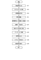
- FIG. 6 is a flowchart showing an example of a procedure for identification by the identification device according to the second embodiment of the present invention.
- the incidental information citation unit 35 of the identification unit 30 acquires this related information from the database 40 or the like and determines the determination result display unit 34. Output to. This related information is displayed together with the identification result on the determination result display unit 34.
- FIG. 7 is a flowchart showing an example of a procedure for identification by the identification device according to the third embodiment of the present invention.
- the processing of S11 to S15 by the measuring unit 20 described in the first embodiment is performed.
- the feature amount generation unit 31 of the identification unit 30 is a teacher that sets a feature amount representing the acoustic frequency characteristics of the object to be identified and an object ID given to the feature amount. Generate data.
- the teacher data may be generated based on the above-mentioned pre-created registration data extracted from the database 40. Further, instead of generating teacher data, measured data given from the outside may be adopted as teacher data. That is, the generation of teacher data by the feature amount generation unit 31 is not essential.
- the analysis model generation unit 36 of the identification unit 30 inputs the generated feature amount.
- the analysis model generation unit 36 generates and learns an analysis model that outputs an object ID as a label and a reference value that is a difference with respect to the input for this input.
- a generally known machine learning method (library) is used for the analysis model and its learning.
- an algorithm for model generation (algorithm), for example, a support vector machine (SVM: Support Vector Machine) or a neural network (neural network), etc., performs parameter tuning (tuning) with respect to the teacher data.
- the analysis model is trained so that the optimum output can be obtained by performing it.
- the analysis model thus obtained is registered in the database for the model by the identification determination unit 32 as the analysis model itself or as a parameter of the analysis model.
- the identification determination unit 32 outputs a reference value based on the feature amount generated by the feature amount generation unit 31 and the analysis model.
- the identification determination unit 32 when the SVM is an algorithm for generating an analysis model, the identification determination unit 32 has a similarity to each label of the analysis model with respect to the input of the feature amount. And so on, get a score. The identification determination unit 32 converts the obtained score to obtain a reference value, and outputs the reference value. Further, for example, when the similarity is normalized and expressed between 0 and 1, the identification determination unit 32 can output the reference value as "1- (similarity)".
- the identification determination unit 32 randomly extracts data from the teacher data generated in S31. Generate multiple decision trees based on this data.
- the identification determination unit 32 outputs the number of determination results for each label related to each generated decision tree. The higher the number of determination results, the more desirable the number. Therefore, the identification determination unit 32 outputs "(number of determinations)-(number of determination results)" as a reference value.
- the reference value may be "1-normalized similarity" or may be a value obtained by converting the original similarity by the reciprocal of the similarity.
- the feature amount newly generated for the new identification target object is input to the database 40, and the feature amount of at least one identified object and the new identification target object are input.
- the model in which the value based on the difference from the feature amount is output in association with the object ID uniquely assigned to the object is stored.
- the identification determination unit 32 inputs the newly generated feature amount for the new identification target object into the model, and among the values output from this model, the new identification target The object ID output associated with the value indicating the highest relevance (based on similarity or reference value) with the feature amount of the object is determined as the object ID of the object to be newly identified. By this determination, the identification determination unit 32 identifies a new object to be identified.
- FIG. 8 is a flowchart showing an example of a procedure for identification by the identification device according to the fourth embodiment of the present invention. First, the processing of S11 to S15 by the measuring unit 20 described in the first embodiment is performed. Next, the processing of S31 to S33 by the identification unit 30 described in the third embodiment is performed.
- the identification determination unit 32 of the identification unit 30 acquires a list of reference values by inputting test data into the analysis model.
- the determination result evaluation unit 33 identifies the smallest reference value in the list of reference values by using the list of reference values acquired in S41.
- the determination result evaluation unit 33 outputs the same feature amount as the specified reference value in the registered data and the object ID associated with the feature amount as the identification result of the object to be identified. After this output, as S19 described in the first embodiment, the determination result display unit 34 displays the identification result output by the determination result evaluation unit 33.
- the determination result evaluation unit 33 sets a threshold value related to the determination related to the output of the identification result in the reference value, and only when the reference value is smaller than the threshold value, the same feature amount as the reference value and this feature amount are used.
- the object ID associated with the feature amount may be determined as the identification result of the object to be identified, and this result may be output.
- the measuring device consists of a vibration generator and a vibration detector.
- the vibration generator and vibration detector are attached to any outer edge of the object to be identified.
- the vibration generator and the vibration detector are arranged so as not to come into contact with each other, and both the vibration generator and the vibration detector are fixed so as to be in contact with the bottom surface of the object. Measurement device is provided.
- the form and material of the measuring device are not limited.
- the measuring device By fixing the measuring device in this way, it is possible to prevent the error of the feature amount based on the vibration with respect to the object to be identified from fluctuating for each measurement. Further, unique identification is given to each of the plurality of vibration generators and the plurality of vibration detectors, and in addition to the above-mentioned feature quantities representing acoustic frequency characteristics and the like, the vibration generator used for the measurement. And, together with the identifier of the vibration detector, it may be registered in the database 40 as additional information of the registration data and used for identifying the object.
- the feature amount of the object identified by the previous identification process detects an identifier uniquely assigned to the vibration generator that generated the vibration related to the previous identification, and the vibration related to the previous identification.
- An identifier uniquely assigned to the vibration detector is associated and stored.
- the feature amount generation unit 31 of the identification unit 30 generates a new feature amount indicating the frequency characteristic based on the new vibration detected for the new object to be identified.
- the identification determination unit 32 of the identification unit 30 is given to the new identification target object by the vibration generator and the identifier given to the vibration generator that generated the new vibration given to the new identification target object.
- the feature amount of the identified object associated with the identifier given to the vibration detector that has detected the new vibration propagating inside the object is extracted from the database 40.
- the identification determination unit 32 identifies a new object to be identified based on the feature amount newly generated by the feature amount generation unit 31 and the extracted feature amount.
- a plurality of sets of vibration generators and a plurality of sets of vibration detectors correspond to a feature quantity of one identified object, a plurality or all sets of these sets are used. It may be registered in the database 40.
- the identification determination unit is based on the identifier given to the set of the vibration generator and the vibration detector and the feature amount generated based on the vibration of the vibration generator and the vibration detector belonging to each set.
- the 32 may calculate the above-mentioned reference value for each generated feature amount, and make a determination regarding the identification of a new object to be identified for each of the calculated reference values, or each of the generated features.
- a reference value integrated by a weighted sum of reference values calculated from the quantity may be calculated, and a new identification target object may be identified based on the calculated reference value.
- FIG. 9 is a diagram showing an example of the appearance of the measuring device.
- An example of the form of the vibration generator and the vibration detector at this time is a plate in which the piezoelectric elements as shown in FIG. 9 are arranged in an array.
- the external shape of the measuring device may be a flat surface as shown in FIG. 9 or may have an uneven shape. In this plate, it is assumed that the piezoelectric elements do not come into contact with each other.
- the vibration generator and the vibration detector can be arbitrarily selected.
- the database 40 stores in advance information indicating the contact surface with the object in the vibration generator, information indicating the contact surface with the object in the vibration detector, and determination information indicating the surface of the object to be identified. ..
- the identification determination unit 32 acoustically selects a vibration generator whose contact surface with the object matches the surface of the object to be identified among the plurality of vibration generators based on the determination information stored in the database 40. It can be selected as a vibration generator used for signal generation by the signal generation unit 22. Further, the identification determination unit 32 acoustically selects a vibration detector whose contact surface with the object matches the surface of the object to be identified among the plurality of vibration detectors based on the determination information stored in the database 40. It can be selected as a vibration detector used for signal reception by the signal receiving unit 23.
- the determination information includes information related to the vibration generator and the vibration detector having a relative positional relationship.
- the identification determination unit 32 selects one of the vibration generator and the vibration detector having a relative positional relationship as described above based on the determination information stored in the database 40, and then the relative positional relationship. The other of the vibration generator and the vibration detector in may be further selected. Further, when there are a plurality of vibration generator candidates whose contact surface with the object matches the surface of the object to be identified, the identification determination unit 32 refers to each of these candidates with the object in the vibration generator.
- the reference value indicating the difference between the contact surface and the surface of the object is obtained, and the candidate related to the smallest reference value among the obtained reference values, that is, the candidate whose contact surface with the object is most similar to the surface of the object to be identified is selected. You may choose. The same applies when there are a plurality of vibration detector candidates whose contact surfaces with the object match the surface of the object to be identified.
- At least one set of vibration generators and vibration detectors comes into contact with the bottom surface of the object indicated by the registration data stored in the database 40 and having a plurality of vibration generators and vibration detectors, respectively.
- the arrangement may be made as follows. By using any one set from the set of the vibration generator and the vibration detector in this way, it is possible to correspond to the identified object represented by the registered data having various bottom shapes.
- FIG. 10 is a diagram showing an example of the appearance of the vibration generator. Further, in the vibration generator, a form in which a flexible material capable of acoustic propagation such as silicon as shown in FIG. 10 is used is applied to a portion of the vibration generator which is a contact surface with an object to be identified. You may. With this form, even if the contact surface of the bottom surface of the object has various bottom surface shapes such as a spherical surface, the above-mentioned flexible material of the vibration generator is deformed according to this bottom surface, so that the object Vibration can be efficiently transmitted to the inside.
- a form in which a flexible material capable of acoustic propagation such as silicon as shown in FIG. 10 is used is applied to a portion of the vibration generator which is a contact surface with an object to be identified. You may. With this form, even if the contact surface of the bottom surface of the object has various bottom surface shapes such as a spherical surface, the above-mentioned flexible material of the vibration generator is
- the third and fourth embodiments described above have been described.
- the analysis by the analysis model can be applied to the identification unit 30. That is, the third or fourth embodiment and the fifth embodiment may be combined.
- FIG. 11 is a diagram showing an example of the functional configuration of the object model generator according to the sixth embodiment of the present invention.
- the object model generation device according to the sixth embodiment of the present invention has a measurement unit selection unit 61 and an optimization unit 62.
- the measuring unit selection unit 61 selects a possible combination of the vibration generator and the vibration detector.
- the optimization unit 62 generates a bottom shape model showing the bottom shape of the model input to the 3D printer from the data of the model of the object and the shape data of the measuring device described in the fifth embodiment.
- the shape of the bottom surface is not particularly limited as long as the unevenness meshes with the contact surface of the vibration generator or the contact surface of the vibration detector.
- FIG. 12 is a flowchart showing an example of a procedure related to object model generation using the object model generation device according to the sixth embodiment of the present invention.
- the measuring unit selection unit 61 selects all possible combinations of the vibration generator and the vibration detector of the measuring device.
- the optimization unit 62 is stored in the database 40 so that the connection between the object indicated by the model input to the 3D printer and the bottom shape model of the object becomes smooth, that is, continuously changes. From the pre-registered bottom shape model (base measurement unit shape data) and the joining orientation of the object and bottom shape model, the optimum bottom shape model and the above joining orientation that satisfy the predetermined conditions are selected. Select and output the selected result.
- This predetermined condition is, for example, one or more of the amount of material at the time of injection of the object by the 3D printer, the price, the injection time, the strength of the object, and the like.
- the above-mentioned direction of joining is the angle formed between the reference position of the object and the reference position of the bottom shape model on the plane of the bottom surface of the object, for example, clockwise.
- the direction of the joint may be an angle of inclination formed by the object and the bottom shape model, if necessary, in consideration of the center of gravity and the like so that the object can be installed in a place other than the horizontal plane.
- the object generation device generates a model of the entire object based on the output by the optimization unit 62.
- This model is passed to the 3D printer, a 3D object is ejected and generated.
- the bottom surface shape model may be a model having a concave shape corresponding to the shape shown in, for example, FIG. 9 of the vibration generator and the vibration detector. With such a shape, the positioning at the time of measurement by the measuring device becomes easy, and the object can be stably installed even at the time of normal use of the object and the measurement by the measuring device.
- one embodiment of the present invention it is also applicable to an object to which a low filling factor is set and output by a 3D printer. That is, it can be adapted independently of the filling rate of the object.
- the inside of the object to be identified is an acoustic propagation path. Therefore, as long as it has an integrated structure inside, it can be adapted to an object made of a translucent material or a material capable of sound wave propagation such as metal, and it is not necessary to provide an opening in the object. .. This allows the object to be identified without any structural restrictions. Further, the acoustic frequency is shown and the feature amount and the object ID are associated with each other, so that the object can be identified from the feature amount.
- FIG. 13 is a block diagram showing an example of the hardware configuration of the object identification device according to the embodiment of the present invention.
- the object identification device 100 according to the above embodiment is composed of, for example, a server computer or a personal computer, and is a hardware processor 111A such as a CPU. Has. Then, the program memory 111B, the data memory 112, the input / output interface 113, and the communication interface 114 are connected to the hardware processor 111A via the bus 120.
- the communication interface 114 includes, for example, one or more wireless communication interface units (units), and enables information to be transmitted / received to / from the communication network NW.
- the wireless interface an interface adopting a low-power wireless data communication standard such as a wireless LAN is used.
- An input device (device) 200 for an administrator and an output device 300 may be connected to the input / output interface 113.
- the program memory 111B is a non-volatile memory (non-volatile memory) that can be written and read at any time, such as an HDD (Hard Disk Drive) or an SSD (Solid State Drive), as a non-temporary tangible storage medium. It is used in combination with a non-volatile memory such as a ROM (Read Only Memory), and stores programs necessary for executing various control processes according to one embodiment.
- non-volatile memory non-volatile memory
- HDD Hard Disk Drive
- SSD Solid State Drive
- ROM Read Only Memory
- the data memory 112 is used as a tangible storage medium, for example, in combination with the above-mentioned non-volatile memory and a volatile memory such as RAM (Random Access Memory), and various processes are performed. It is used to store various data acquired and created in the process.
- RAM Random Access Memory
- the object identification device 100 is configured as a data processing device having each part in the measurement unit 20 and each part in the identification unit 30 shown in FIG. 2 as a processing function unit by software. Can be done.
- the database 40 can be configured by using the data memory 112 shown in FIG.
- the storage area in the data memory 112 is not an essential configuration for the object identification device 100, and is, for example, an external storage medium such as a USB (Universal Serial Bus) memory or a database server (database) arranged in the cloud. It may be an area provided in a storage device such as server).
- USB Universal Serial Bus
- database server database
- Each of the processing function units in each part of the object identification device 100 can be realized by reading the program stored in the program memory 111B by the hardware processor 111A and executing the program.
- a part or all of these processing function units may be in various other formats including integrated circuits such as integrated circuits (ASIC (Application Specific Integrated Circuit)) or FPGA (Field-Programmable Gate Array) for specific applications. It may be realized.
- ASIC Application Specific Integrated Circuit
- FPGA Field-Programmable Gate Array
- a first aspect of the identification device includes a vibration generating unit that has an integrated structure and generates a first vibration given to a three-dimensional object to be identified by a vibration generator.
- the acquisition unit that acquires the detection signal corresponding to the second vibration propagating inside the three-dimensional object from the vibration detector among the first vibrations given to the three-dimensional object, and the acquired detection signal.
- a feature amount generating unit that generates a feature amount indicating the frequency characteristic of the second vibration and a storage that stores the feature amount indicating the frequency characteristic based on the vibration propagating inside the identified three-dimensional object. It includes the feature amount stored in the apparatus and an identification unit that identifies the three-dimensional object to be identified based on the feature amount generated by the feature amount generation unit.
- a second aspect of the identification device of the present invention is, in the first aspect, an identifier uniquely assigned to the vibration generator that generated the first vibration related to identification, and the second vibration related to identification.
- An identifier uniquely assigned to the vibration detector that has detected the above is associated with the feature amount of the three-dimensional object identified by the identification unit and stored in the storage device, and the feature amount generation unit is the three-dimensional object to be identified.
- the identification unit Based on the detection signal acquired by the acquisition unit, a feature amount indicating a frequency characteristic is generated, and the identification unit generates a vibration generator that generates the first vibration given to the three-dimensional object to be identified.
- the feature amount of the identified three-dimensional object associated with the assigned identifier and the identifier given to the vibration detector that detected the second vibration is extracted from the feature amount stored in the storage device.
- the feature amount generated by the feature amount generation unit, and the three-dimensional object to be identified are identified based on the extracted feature amount.
- a third aspect of the identification device of the present invention is, in the first or second aspect, information indicating a contact surface with a three-dimensional object in the vibration generator and information indicating a contact surface with a three-dimensional object in the vibration detector.
- information indicating the surface of the three-dimensional object to be identified is stored in the storage device, and the identification unit refers to the three-dimensional object among the plurality of vibration generators based on the information stored in the storage device.
- the vibration generator whose contact surface matches the surface of the three-dimensional object to be identified is selected as the vibration generator used to generate the vibration, and a plurality of the vibrations are based on the information stored in the storage device.
- the vibration detector whose contact surface with the three-dimensional object matches the surface of the three-dimensional object to be identified is selected as the vibration detector used for the acquisition.
- a fourth aspect of the identification device of the present invention is, in the first or second aspect, at least one of the three-dimensional objects to be identified, in which the feature amount generated by the feature amount generation unit is input and identified.
- a model that outputs a value based on the difference between the feature amount of the three-dimensional object and the feature amount of the three-dimensional object to be identified in association with the identifier uniquely given to the three-dimensional object is stored in the storage device, and the model is stored in the storage device.
- the identification unit inputs the feature amount generated by the feature amount generation unit to the model for the three-dimensional object to be identified, and from the model.
- the identifier output associated with the value indicating the highest relevance to the feature amount of the three-dimensional object to be identified is determined as the identifier of the three-dimensional object to be identified. , The three-dimensional object to be identified is identified.
- a fifth aspect of the identification device of the present invention is, in the fourth aspect, an identifier given to the vibration generator that generated the vibration given to the three-dimensional object to be identified, and the identification object by the vibration generator.
- An identifier given to the three-dimensional object and given to the vibration detector that detects the vibration propagating inside the three-dimensional object is further input to the model, and the input identifier is given to at least one identified.
- a value based on the difference between the feature amount of the three-dimensional object and the feature amount of the three-dimensional object to be identified is associated with the identifier and output from the model.
- the model has a feature amount generated for the three-dimensional object to be identified and an identifier uniquely assigned to the three-dimensional object to be identified. Learned based on the associated teacher data.
- the first aspect of the identification method is the identification method performed by the identification device, which vibrates the first vibration given to the three-dimensional object to be identified, which has an integrated structure. It is generated by a generator, and among the first vibrations given to the three-dimensional object, a detection signal corresponding to the second vibration propagating inside the three-dimensional object is acquired from the vibration detector. Based on the acquired detection signal, a feature amount showing the frequency characteristic of the second vibration is generated, and a feature amount showing the frequency characteristic based on the vibration propagated inside the identified three-dimensional object.
- the feature amount stored in the storage device in which the device is stored and the three-dimensional object to be identified are identified based on the generated feature amount.
- the generated feature amount of the three-dimensional object to be identified is input, and the feature of at least one three-dimensional object that has been identified.
- a model for outputting a value based on the difference between the quantity and the feature quantity of the three-dimensional object to be identified in association with an identifier uniquely assigned to the three-dimensional object is stored in the storage device, and the model is generated.
- the identification means inputting the generated feature amount to the model for the three-dimensional object to be identified, and among the values output from the model, the identification target.
- the generation of the feature amount is the feature amount generated for the three-dimensional object to be identified and the identification target.
- the model is trained on the basis of the generated teacher data, including generating teacher data associated with an identifier uniquely assigned to the three-dimensional object.
- One aspect of the identification processing program causes the processor to function as each of the parts of the identification device in any one of the first to sixth aspects.
- One aspect of the generator according to one embodiment of the present invention is the shape of a vibration generator that generates the first vibration given to the three-dimensional object to be identified, and the first vibration given to the three-dimensional object.
- a model of a three-dimensional object to be identified which has a contact surface suitable for the propagation of the second vibration, based on the shape of the vibration detector that detects the second vibration propagating inside the three-dimensional object. It has a generation unit to generate.
- One aspect of the generation method according to the embodiment of the present invention is the generation method performed by the generation device, the shape of the vibration generator that generates the first vibration given to the three-dimensional object to be identified, and the above-mentioned.
- a contact surface suitable for propagating the second vibration based on the shape of the vibration detector that detects the second vibration propagating inside the three-dimensional object among the first vibrations given to the three-dimensional object.
- One aspect of the generation processing program according to the embodiment of the present invention causes the processor to function as a generation unit of the generation device in the above aspect.
- the vibration generator generates the first vibration given to the three-dimensional object to be identified, which has an integrated structure, and the first vibration is generated.
- a detection signal corresponding to the second vibration propagating inside the three-dimensional object is acquired from the vibration detector, and based on the acquired detection signal, a feature quantity indicating the frequency characteristic of the second vibration is obtained.
- the three-dimensional object to be identified is identified based on the feature amount generated and the feature amount showing the frequency characteristic based on the vibration propagated inside the identified three-dimensional object.
- the identifier of the vibration generator that generated the first vibration related to the identification and the vibration detector that detected the second vibration related to the identification is associated with the feature quantity of the identified three-dimensional object and stored in the storage device, and based on the detection signal acquired for the three-dimensional object to be identified, the feature quantity indicating the frequency characteristic is generated, and the three-dimensional object to be identified is generated.
- the identified feature quantities of the three-dimensional object associated with the identifier of the vibration generator that generated the first vibration and the identifier of the vibration detector that detected the second vibration are stored in the storage device. It is extracted from the feature amount, and the three-dimensional object to be identified is identified based on the generated feature amount and the extracted feature amount. As a result, it is possible to accurately identify a three-dimensional object according to the individual vibration generator and vibration detector.
- the information indicating the contact surface with the three-dimensional object in the vibration generator and the contact surface with the three-dimensional object in the vibration detector stored in the storage device is vibrated based on the information indicating the above and the information indicating the surface of the three-dimensional object to be identified.
- the vibration detector whose contact surface with the three-dimensional object matches the surface of the three-dimensional object to be identified is the vibration used to acquire the detection signal. Select as a detector. This makes it possible to accurately identify a three-dimensional object by using a vibration generator and a vibration detector suitable for the surface of the three-dimensional object to be identified.
- the feature amount generated for the three-dimensional object to be identified is input, and the feature amount of at least one identified three-dimensional object is newly identified.
- a model that outputs a value based on the difference from the feature amount of the target three-dimensional object in association with the identifier is stored in the storage device, and the model is learned based on the generated feature amount, and the generated feature amount is used as a model.
- the three-dimensional object to be identified is identified based on the value indicating that the relationship with the feature amount of the three-dimensional object to be identified is the highest. As a result, it is possible to appropriately identify the three-dimensional object by using the identified three-dimensional object.
- the identifier given to the vibration generator that generated the vibration and the second aspect propagating inside the three-dimensional object is further input to the model, and the feature amount of at least one identified three-dimensional object and the feature amount of the three-dimensional object to be identified are given the input identifier.
- the value based on the difference of is associated with the identifier and output from the model.
- the model is applied to the feature amount generated for the new identification target three-dimensional object and the identification target three-dimensional object.
- the assigned identifier is learned based on the associated teacher data. This makes it possible to identify a three-dimensional object with higher accuracy.
- a model of a three-dimensional object to be identified has a contact surface suitable for vibration propagation based on the shapes of the vibration generator and the vibration detector. ..
- the three-dimensional object to be identified can be appropriately represented, and accurate identification can be realized.
- the method described in each embodiment is a program (software means) that can be executed by a computer (computer), for example, a magnetic disk (floppy (registered trademark) disk (Floppy disk), hard disk, etc.), an optical disk, etc. It can be stored in a recording medium such as (optical disc) (CD-ROM, DVD, MO, etc.), semiconductor memory (ROM, RAM, Flash memory, etc.), or transmitted and distributed by a communication medium. ..
- the program stored on the medium side also includes a setting program for configuring the software means (including not only the execution program but also the table and the data structure) to be executed by the computer in the computer.
- a computer that realizes this device reads a program recorded on a recording medium, constructs software means by a setting program in some cases, and executes the above-mentioned processing by controlling the operation by the software means.
- the recording medium referred to in the present specification is not limited to distribution, and includes storage media such as magnetic disks and semiconductor memories provided in devices connected inside a computer or via a network.
- the present invention is not limited to the above embodiment, and can be variously modified at the implementation stage without departing from the gist thereof.
- each embodiment may be carried out in combination as appropriate, in which case the combined effect can be obtained.
- the above-described embodiment includes various inventions, and various inventions can be extracted by a combination selected from a plurality of disclosed constituent requirements. For example, even if some constituent requirements are deleted from all the constituent requirements shown in the embodiment, if the problem can be solved and the effect is obtained, the configuration in which the constituent requirements are deleted can be extracted as an invention.
Landscapes
- Physics & Mathematics (AREA)
- Life Sciences & Earth Sciences (AREA)
- General Physics & Mathematics (AREA)
- Immunology (AREA)
- Health & Medical Sciences (AREA)
- Chemical & Material Sciences (AREA)
- Analytical Chemistry (AREA)
- Biochemistry (AREA)
- General Health & Medical Sciences (AREA)
- Pathology (AREA)
- Engineering & Computer Science (AREA)
- Signal Processing (AREA)
- Acoustics & Sound (AREA)
- Mathematical Physics (AREA)
- Spectroscopy & Molecular Physics (AREA)
- Environmental & Geological Engineering (AREA)
- Geology (AREA)
- Remote Sensing (AREA)
- General Life Sciences & Earth Sciences (AREA)
- Geophysics (AREA)
- Measurement Of Mechanical Vibrations Or Ultrasonic Waves (AREA)
- Testing Of Devices, Machine Parts, Or Other Structures Thereof (AREA)
- Geophysics And Detection Of Objects (AREA)
- Investigating Or Analyzing Materials By The Use Of Ultrasonic Waves (AREA)
Abstract
一実施形態に係る識別装置は、一体化された構造を有する、識別対象の立体物に与えられる第1の振動を振動発生器により発生させる振動発生部と、前記立体物に与えられた前記第1の振動のうちで前記立体物の内部を伝搬した第2の振動に対応する検出信号を振動検出器から取得する取得部と、前記取得された前記検出信号をもとに、前記第2の振動の周波数特性を示す特徴量を生成する特徴量生成部と、識別済みの立体物の内部を伝搬した振動に基づく、周波数特性を示す特徴量が記憶される記憶装置に記憶される前記特徴量、および前記特徴量生成部により生成された特徴量に基づいて、前記識別対象の立体物を識別する識別部と、を有する。
Description
本発明の実施形態は、識別装置、識別方法、識別処理プログラム、生成装置、生成方法、および生成処理プログラムに関する。
3D(3次元(three dimensions))プリンタ(printer)により3Dプリント(print)された立体物であるオブジェクト(object)を識別するために、3Dプリントされたオブジェクトに情報を埋め込む手法がある。
第1の手法として、3Dプリントされたオブジェクトの内部に空洞が設けられた状態で、光の反射特性の違いを利用して、空洞が存在する部位と存在しない部位とを区別し、空洞の有無から情報を復元する手法がある(例えば、非特許文献1を参照)。
また、第2の手法として、オブジェクト内部に設けられた空洞内の音の響き方が利用された情報埋め込みおよび識別手法も存在する(例えば、非特許文献2を参照)。
Dingzeyu Li, Avinash S. Nair, Shree K. Nayar, Changxi Zheng. AirCode: Unobtrusive Physical Tags for Digital Fabrication. In Proceedings of the Annual ACM Symposium on User Interface Software & Technology (UIST ’17). ACM.
Dingzeyu Li, David I. W. Levin, Wojciech Matusik, and Changxi Zheng. 2016. Acoustic Voxels: Computational Optimization of Modular Acoustic Filters. ACM Trans. Graph. 35, 4, Article 88 (July 2016), 12 pages.
しかしながら、上記第1の手法では、内部に設けられる空洞以外の部位を密な構造にする必要があるが、3Dプリント時に低い充填率が設定されて印刷されたオブジェクトには適用できない。
また、この手法では、光の反射特性の違いが利用されるため、光を透過する半透明な材料が用いられてオブジェクトが3Dプリントされる必要があり、光を透過しない不透明な素材、又は光を反射する金属素材が用いられて3Dプリントされたオブジェクトには適用できない等、適用可能な印刷素材が制約される。
また、上記第2の手法は、対象物体の任意箇所に設けられる空洞入口から音を入力し、この空洞を通過した音の出力を空洞出口において読み取る必要がある。このため、オブジェクトに少なくとも2か所の開口部が設けられる必要があり、適用できる物体構造が制約される。
この発明は、上記事情に着目してなされたもので、その目的とするところは、立体物を適切に識別することができるようにした識別装置、識別方法、識別処理プログラム、生成装置、生成方法、および生成処理プログラムを提供することにある。
上記目的を達成するために、この発明の一実施形態に係る識別装置の一つの態様は、一体化された構造を有する、識別対象の立体物に与えられる第1の振動を振動発生器により発生させる振動発生部と、前記立体物に与えられた前記第1の振動のうちで前記立体物の内部を伝搬した第2の振動に対応する検出信号を振動検出器から取得する取得部と、前記取得された前記検出信号をもとに、前記第2の振動の周波数特性を示す特徴量を生成する特徴量生成部と、識別済みの立体物の内部を伝搬した振動に基づく、周波数特性を示す特徴量が記憶される記憶装置に記憶される前記特徴量、および前記特徴量生成部により生成された特徴量に基づいて、前記識別対象の立体物を識別する識別部と、を備える。
本発明の一実施形態に係る識別方法の一つの態様は、識別装置により行なわれる識別方法であって、一体化された構造を有する、識別対象の立体物に与えられる第1の振動を振動発生器により発生させることと、前記立体物に与えられた前記第1の振動のうちで前記立体物の内部を伝搬した第2の振動に対応する検出信号を振動検出器から取得することと、前記取得された前記検出信号をもとに、前記第2の振動の周波数特性を示す特徴量を生成することと、識別済みの立体物の内部を伝搬した振動に基づく、周波数特性を示す特徴量が記憶される記憶装置に記憶される前記特徴量、および前記生成された特徴量に基づいて、前記識別対象の立体物を識別することと、を備える。
上記目的を達成するために、この発明の一実施形態に係る生成装置の一つの態様は、識別対象の立体物へ与えられる第1の振動を発生する振動発生器の形状、および前記立体物に与えられた前記第1の振動のうちで前記立体物の内部を伝搬した第2の振動を検出する振動検出器の形状に基づいて、前記第2の振動の伝搬に適切な接触面を有する、識別対象の立体物のモデルを生成する生成部を備える。
本発明の一実施形態に係る生成方法の一つの態様は、生成装置により行なわれる生成方法であって、識別対象の立体物へ与えられる第1の振動を発生する振動発生器の形状、および前記立体物に与えられた前記第1の振動のうちで前記立体物の内部を伝搬した第2の振動を検出する振動検出器の形状に基づいて、前記第2の振動の伝搬に適切な接触面を有する、識別対象の立体物のモデルを生成すること、を備える。
本発明の各態様によれば、立体物を適切に識別することが可能になる。
以下、図面を参照しながら、この発明に係わる一実施形態を説明する。
本発明の一実施形態に係る識別装置は、オブジェクト内部を伝搬する振動が解析されて得られる音響スペクトル(spectrum)を解析し、この音響スペクトルの違いに基づいてオブジェクトを識別する。この識別装置は、形状、素材、および境界条件等によって変化する共振特性を音響スペクトルにより解析し、このスペクトルの違いに基づいてオブジェクトを識別する。
本発明の一実施形態に係る識別装置は、オブジェクト内部を伝搬する振動が解析されて得られる音響スペクトル(spectrum)を解析し、この音響スペクトルの違いに基づいてオブジェクトを識別する。この識別装置は、形状、素材、および境界条件等によって変化する共振特性を音響スペクトルにより解析し、このスペクトルの違いに基づいてオブジェクトを識別する。
本発明の一実施形態では、振動が伝搬する媒体であれば、充填率は問わずに識別対象のオブジェクトとして適用され得る。また、本発明の一実施形態では、音波の減衰率が低い素材であれば識別対象のオブジェクトとして適用され得、このオブジェクトに開口部が設けられる必要もない。
また、本発明の一実施形態では、識別対象のオブジェクトが、ある1つの対象Aであるか否かだけでなく、任意に選択可能な、識別対象である全てのオブジェクトのデータを用いて、分類モデルであるオブジェクト識別モデルを生成する。このため、この違いに応じて、識別対象のオブジェクトが、どのオブジェクトかを区別すること、例えば対象A、対象B、および対象Cをそれぞれ区別することが可能である。
すなわち、識別装置は、オブジェクト識別モデルを用いることで、真贋判定だけでなくオブジェクトの識別も同時に行なうことができる。
また、識別装置は、音響スペクトルと各オブジェクトに固有のオブジェクトID(identification)とが結び付けられることによって、音響スペクトルからオブジェクトを識別できる。
また、複数の計測部分が用意されること、又は計測部分の形状とオブジェクトの形状とが工夫されることにより、識別装置による識別精度が向上され得る。
また、識別装置は、音響スペクトルと各オブジェクトに固有のオブジェクトID(identification)とが結び付けられることによって、音響スペクトルからオブジェクトを識別できる。
また、複数の計測部分が用意されること、又は計測部分の形状とオブジェクトの形状とが工夫されることにより、識別装置による識別精度が向上され得る。
図1は、本発明の一実施形態に係るオブジェクト識別装置の適用例を示す図である。
本発明の一実施形態に係るオブジェクト識別装置100は、中央処理ユニット(Central Processing Unit:CPU)、プログラムメモリ(program memory)、および演算用メモリなどが備えられたコンピュータ(computer)として構成され得る。この実施形態が実施されるために必要な機能として、図1に示されるように、オブジェクト10を識別するための構成として、オブジェクト識別装置100は、測定部20、識別部30、およびデータベース(database)40を有する。測定部20は共振特性取得部である。
本発明の一実施形態に係るオブジェクト識別装置100は、中央処理ユニット(Central Processing Unit:CPU)、プログラムメモリ(program memory)、および演算用メモリなどが備えられたコンピュータ(computer)として構成され得る。この実施形態が実施されるために必要な機能として、図1に示されるように、オブジェクト10を識別するための構成として、オブジェクト識別装置100は、測定部20、識別部30、およびデータベース(database)40を有する。測定部20は共振特性取得部である。
図2は、本発明の一実施形態に係るオブジェクト識別装置の測定部及び識別部の機能構成例を示すブロック図である。
図2に示されるように、測定部20は、音響信号生成部21、音響信号発生部22、音響信号受信部23、音響信号増幅部24、および音響信号抽出部25を有する。
図2に示されるように、測定部20は、音響信号生成部21、音響信号発生部22、音響信号受信部23、音響信号増幅部24、および音響信号抽出部25を有する。
また、図2に示されるように、識別部30は、特徴量生成部31、識別判定部32、判定結果評価部33、および判定結果表示部34を有する。また、識別部30は、付随情報引用部35、および解析モデル生成部36を有することができる。これら、付随情報引用部35および解析モデル生成部36の機能については後述する。
オブジェクト識別装置100内の各部は、プログラムメモリに格納されたプログラムを上記CPUに実行させることにより実現され得る。なお、オブジェクト識別装置100は、ハードウエアで構成され得るが、後述するフローチャートに示された手順を備えるプログラムが、媒体もしくは通信回線を介して周知のコンピュータにインストール(install)された上で、このコンピュータとデータベース40との組み合わせ、又はデータベース40を有するコンピュータなどによっても実現され得る。
図3,4は、識別対象のオブジェクトの一例を示す図である。
図3に示された例では、7つのオブジェクト(図3中のa,b,c,d,e,fおよびg)がそれぞれ示されており、全体として、オブジェクト内部における一体化された構造を有する。
図3に示された例では、7つのオブジェクト(図3中のa,b,c,d,e,fおよびg)がそれぞれ示されており、全体として、オブジェクト内部における一体化された構造を有する。
本発明の一実施形態では、音響信号発生部22に接続される振動発生器、および音響信号受信部23に接続される振動検出器を、対象とするオブジェクトにそれぞれ接触させた際の当該オブジェクトの2点間に、オブジェクト内部における一体化した構造を有しているオブジェクトであれば、先行技術と異なり、オブジェクトの内部構造の充填率に関係なく識別対象のオブジェクトとして適用できる。また、本発明の一実施形態では、半透明素材および金属素材も識別対象のオブジェクトとして適用できる。
上記の振動発生器および振動検出器は、互いに接触しない圧電素子、例えばピエゾ素子(piezoelectric element)により実現され得る。また、この圧電素子は、振動発生器用の素子および振動検出器用の素子として用いられ得る。
上記の振動発生器および振動検出器は、互いに接触しない圧電素子、例えばピエゾ素子(piezoelectric element)により実現され得る。また、この圧電素子は、振動発生器用の素子および振動検出器用の素子として用いられ得る。
測定部20は、超音波帯域の任意の周波数特性を有する音響信号を生成し、圧電素子から当該超音波帯域の振動を識別対象のオブジェクトに与えた上で、このオブジェクトを通過した振動を取得する。
識別部30は、測定部20において取得した振動信号のデータに基づいて、識別対象のオブジェクトを識別し、この識別結果を提示する。
識別部30は、測定部20において取得した振動信号のデータに基づいて、識別対象のオブジェクトを識別し、この識別結果を提示する。
次に、測定部20の各部について説明する。
音響信号生成部21は、音響信号発生部22において発生させる振動の元となる音響信号を生成する。
音響信号発生部22は、音響信号生成部21において生成された音響信号と同一の周波数特性を有する振動を、識別対象のオブジェクトに接触する振動発生器により発生させ、この振動を識別対象のオブジェクトに与える。
音響信号生成部21は、音響信号発生部22において発生させる振動の元となる音響信号を生成する。
音響信号発生部22は、音響信号生成部21において生成された音響信号と同一の周波数特性を有する振動を、識別対象のオブジェクトに接触する振動発生器により発生させ、この振動を識別対象のオブジェクトに与える。
音響信号受信部23は、音響信号発生部22により発生した振動が識別対象のオブジェクトに対して与えられることによる、当該オブジェクトの振動を、識別対象のオブジェクトに接触する振動検出器により検出させて、この振動により示される信号を受信する。音響信号発生部22および音響信号受信部23は、オーディオインターフェース(audio interface)により実現され得る。
音響信号増幅部24は、音響信号受信部23において受信された振動から信号を得て、この信号を増幅する。
音響信号抽出部25は、音響信号増幅部24により増幅された信号を時間軸の一定区間ごとに抽出する。
音響信号抽出部25は、音響信号増幅部24により増幅された信号を時間軸の一定区間ごとに抽出する。
次に、識別部30の各部について説明する。
特徴量生成部31は、測定部20の音響信号抽出部25により抽出された信号の波形に基づき、識別対象のオブジェクトを識別するための特徴量を生成する。
識別判定部32は、特徴量生成部31により生成された特徴量をもとに、識別対象のオブジェクトを判定するための数値を求める。
特徴量生成部31は、測定部20の音響信号抽出部25により抽出された信号の波形に基づき、識別対象のオブジェクトを識別するための特徴量を生成する。
識別判定部32は、特徴量生成部31により生成された特徴量をもとに、識別対象のオブジェクトを判定するための数値を求める。
判定結果評価部33は、識別判定部32により求められた数値をもとに、識別対象のオブジェクトを識別する。
判定結果表示部34は、判定結果評価部33による、オブジェクトの識別結果を表示装置などに表示する。
判定結果表示部34は、判定結果評価部33による、オブジェクトの識別結果を表示装置などに表示する。
(第1の実施形態)
次に、本発明の第1の実施形態について説明する。第1の実施形態では、一体化した構造を有するオブジェクトに対して、測定部20から振動として与えられた音響信号が取得(計測)され、この取得された振動の音響周波数特性を表す特徴量に基づいて、識別対象のオブジェクトが識別される。
次に、本発明の第1の実施形態について説明する。第1の実施形態では、一体化した構造を有するオブジェクトに対して、測定部20から振動として与えられた音響信号が取得(計測)され、この取得された振動の音響周波数特性を表す特徴量に基づいて、識別対象のオブジェクトが識別される。
測定部20および識別部30による具体的な処理を以下に示す。図5は、本発明の第1の実施形態に係る識別装置による識別に係る手順の一例を示すフローチャートである。
(S11) 測定部20の音響信号生成部21は、任意に設定されたパラメータ(parameters)に基づく音響信号を生成する。
一例として、音響信号は、20[kHz]から40[kHz]までの周波数帯域で掃引される超音波であるとする。ただし、掃引されるか否か、および他の周波数帯域の利用の有無等の、音響信号の設定は特に限られない。
(S11) 測定部20の音響信号生成部21は、任意に設定されたパラメータ(parameters)に基づく音響信号を生成する。
一例として、音響信号は、20[kHz]から40[kHz]までの周波数帯域で掃引される超音波であるとする。ただし、掃引されるか否か、および他の周波数帯域の利用の有無等の、音響信号の設定は特に限られない。
(S12) 次に、音響信号発生部22に接続される振動発生器と、音響信号受信部23に接続される振動検出器を例えば機構などにより識別対象のオブジェクトに接触させる。例えば、振動発生器、振動検出器は、両面テープ等により、識別対象のオブジェクトの外縁部に貼り付けられ得る。振動発生器は、測定部20の音響信号発生部22と分離されてもよいし、音響信号発生部22と一体であってもよい。同様に、振動検出器は、測定部20の音響信号受信部23と分離されてもよいし、音響信号受信部23と一体であってもよい。
識別対象のオブジェクトと接触しつつ、かつ、振動をオブジェクトに伝搬できる機構、又は当該機構を用いて振動検出器を識別対象のオブジェクトと接触させつつ、かつ、振動をオブジェクトに伝搬できる方法を実現できるのであれば、振動発生器および振動検出器の形態及び素材は特に限られない。
予め設定されたパラメータに基づいて音響信号生成部21で生成された音響信号により、音響信号発生部22は、識別対象のオブジェクトに与えられる振動を振動発生器に発生させる。これにより、識別対象のオブジェクト内に振動が与えられる。
このときの振動は、データベース40に登録されている登録オブジェクトに関する登録データに含まれる特徴量が識別部30により生成される際に用いられた振動に含まれる周波数を含む振動であれば、他の周波数を混在して含む振動でも良い。加えて、振動発生器は上記の圧電素子により構成され得るが、振動を発生させるものであれば形態は特に限られない。
(S13) 振動検出器は、識別対象のオブジェクトに与えられて当該オブジェクトの内部を伝搬してきた振動を検出する。音響信号受信部23は、この検出された振動で示される信号を取得する。
振動発生器から与えられる振動が振動検出器まで伝搬される際に、測定対象のオブジェクトの内部構造は振動の伝搬路として機能する。この伝搬路に応じて与えられた振動の周波数特性はオブジェクトにより変化する。
(S14) 音響信号増幅部24は、音響信号受信部23により取得された振動を振動信号に変換し、この信号を増幅する。
S14の処理は、識別対象のオブジェクトを通過した振動は減衰するので、信号のレベル(level)を処理が可能であるレベルまで増幅される必要があるため、実行される。
S14の処理は、識別対象のオブジェクトを通過した振動は減衰するので、信号のレベル(level)を処理が可能であるレベルまで増幅される必要があるため、実行される。
(S15) 音響信号抽出部25は、音響信号増幅部24により増幅された振動信号を取得し、この取得した信号を時間軸の一定区間ごとに抽出する。
例えば、音響信号抽出部25は、サンプル(sample)数が8192(=213)である信号を取得するごとに振動信号を抽出する。ただし、このサンプル数は特に限られない。
例えば、音響信号抽出部25は、サンプル(sample)数が8192(=213)である信号を取得するごとに振動信号を抽出する。ただし、このサンプル数は特に限られない。
(S16) 識別部30の特徴量生成部31は、音響信号抽出部25により抽出された振動信号に対する高速フーリエ変換(Fast Fourier Transform (FFT))を行なうことで、音響周波数特性等が表される特徴量を生成する。
(S17) 識別対象のオブジェクトを識別するために、識別判定部32は、データベース40に予め登録される、予め識別されたオブジェクトに関する登録データで示される特徴量と、特徴量生成部31により生成された特徴量であるテストデータ(test data)との差である参考値を求める。
登録データとは、データベース40に予め登録された、登録オブジェクトに関する予め計測された特徴量と、この特徴量に付与される一意の識別子(以下オブジェクトID)とが関連付けられたデータである。
参考値は、例えば、最小二乗誤差、またはユークリッド(euclidian)距離等であり、テストデータと登録データとの間の特徴量の類似度が高いほど値が小さい任意の指標であるとする。
参考値は、例えば、最小二乗誤差、またはユークリッド(euclidian)距離等であり、テストデータと登録データとの間の特徴量の類似度が高いほど値が小さい任意の指標であるとする。
(S18) 判定結果評価部33は、識別判定部32により求められた参考値のうち、最も小さい参考値を特定する。判定結果評価部33は、登録データにおける、この特定した参考値と同じ特徴量と、この特徴量に関連付けられる、登録オブジェクトのオブジェクトIDとを、識別対象のオブジェクトの識別結果として出力する。
第1の実施形態では、S11~S18の処理が複数回繰り返され、判定結果評価部33は、出力された回数が最も多いオブジェクトIDを、識別対象のオブジェクトの識別結果としても良い。
別の例として、第1の実施形態では、S11~S17の処理を複数回繰り返され、判定結果評価部33は、S17でそれぞれ出力された参考値のうち最も小さい参考値を特定し、登録データにおける、この特定した参考値と同じ特徴量と、この特徴量に関連付けられる、登録オブジェクトのオブジェクトIDとを、識別対象のオブジェクトの識別結果として出力しても良い。
(S19) 判定結果表示部34は、判定結果評価部33により出力された識別結果を表示する。
(S19) 判定結果表示部34は、判定結果評価部33により出力された識別結果を表示する。
(第2の実施形態)
次に、本発明の第2の実施形態について説明する。以降の各実施形態について、第1の実施形態と重複する説明は省略することがある。第2の実施形態では、識別結果に関連する情報である付加情報が表示される。付加情報の例としては、識別対象の名称、製造者、材質、価格、製造日時、および製造場所等の商品の情報、その商品の使い方等が挙げられる。
次に、本発明の第2の実施形態について説明する。以降の各実施形態について、第1の実施形態と重複する説明は省略することがある。第2の実施形態では、識別結果に関連する情報である付加情報が表示される。付加情報の例としては、識別対象の名称、製造者、材質、価格、製造日時、および製造場所等の商品の情報、その商品の使い方等が挙げられる。
まず、第1の実施形態で説明したS11~S19の処理がなされる。
第2の実施形態では、上記の登録データで示される、識別対象オブジェクトに対するオブジェクトIDと、音響周波数特性等が表される特徴量とともに、オブジェクトの関連情報がさらに関連付けられたデータがデータベース40に予め登録されても良い。
第2の実施形態では、上記の登録データで示される、識別対象オブジェクトに対するオブジェクトIDと、音響周波数特性等が表される特徴量とともに、オブジェクトの関連情報がさらに関連付けられたデータがデータベース40に予め登録されても良い。
図6は、本発明の第2の実施形態に係る識別装置による識別に係る手順の一例を示すフローチャートである。
(S21) 識別部30の付随情報引用部35は、判定結果表示部34により表示された識別結果に関連した関連情報がある場合、この関連情報をデータベース40等から取得して判定結果表示部34に出力する。この関連情報は、判定結果表示部34において識別結果とともに表示される。
(S21) 識別部30の付随情報引用部35は、判定結果表示部34により表示された識別結果に関連した関連情報がある場合、この関連情報をデータベース40等から取得して判定結果表示部34に出力する。この関連情報は、判定結果表示部34において識別結果とともに表示される。
(第3の実施形態)
次に、本発明の第3の実施形態について説明する。
第3の実施形態では、第1の実施形態で説明した識別部30の処理において機械学習が用いられたときの第1の例を述べる。
次に、本発明の第3の実施形態について説明する。
第3の実施形態では、第1の実施形態で説明した識別部30の処理において機械学習が用いられたときの第1の例を述べる。
図7は、本発明の第3の実施形態に係る識別装置による識別に係る手順の一例を示すフローチャートである。
まず、第1の実施形態で説明した、測定部20によるS11~S15の処理がなされる。
(S31) そして、識別部30の特徴量生成部31は、識別対象のオブジェクトの音響周波数特性等が表される特徴量と、この特徴量に対して付与されたオブジェクトIDとを組とする教師データを生成する。
まず、第1の実施形態で説明した、測定部20によるS11~S15の処理がなされる。
(S31) そして、識別部30の特徴量生成部31は、識別対象のオブジェクトの音響周波数特性等が表される特徴量と、この特徴量に対して付与されたオブジェクトIDとを組とする教師データを生成する。
教師データは、データベース40から抽出された、上記の予め作成された登録データに基づいて生成されても良い。また、教師データが生成されるのではなく、外部から与えられた測定済みのデータが教師データとして採用されても良い。つまり、特徴量生成部31による教師データの生成は必須ではない。
(S32) 識別部30の解析モデル生成部36は、上記生成された特徴量を入力する。解析モデル生成部36は、この入力に対して、ラベル(label)としてのオブジェクトIDと、当該入力に対する差である参考値とをそれぞれ出力する解析モデルを生成および学習する。
解析モデルおよびその学習には一般的に公知な機械学習手法(ライブラリ(library))が用いられる。解析モデル生成部36は、モデル生成用のアルゴリズム(algorithm)、例えばサポートベクタマシン(SVM:Support Vector Machine )またはニューラルネットワーク(neural network)などが、教師データに対してパラメータのチューニング(tuning)等が実施されることにより最適な出力が得られるよう、解析モデルを学習する。
(S33) このように得られた解析モデルは、解析モデル自体または解析モデルのパラメータとして、識別判定部32によりモデル用のデータベースに登録される。
(S34) 識別判定部32は、特徴量生成部31により生成された特徴量と解析モデルとに基づいて、参考値を出力する。
(S34) 識別判定部32は、特徴量生成部31により生成された特徴量と解析モデルとに基づいて、参考値を出力する。
S34の第1の例として、例えば解析モデル生成部36において、SVMが解析モデル生成用のアルゴリズムである場合、識別判定部32は、特徴量の入力に対して解析モデルが有する各ラベルに対する類似度等を示すスコア(score)を得る。
識別判定部32は、この得られたスコアを変換して参考値を得て、これを出力する。また、例えば、類似度が正規化されて0から1の間で表現される場合、識別判定部32は、参考値を「1-(類似度)」として出力できる。
識別判定部32は、この得られたスコアを変換して参考値を得て、これを出力する。また、例えば、類似度が正規化されて0から1の間で表現される場合、識別判定部32は、参考値を「1-(類似度)」として出力できる。
S34の第2の例として、例えば解析モデル生成部36において、Random Forestが解析モデル生成用のアルゴリズムである場合、識別判定部32は、S31で生成された教師データからランダムにデータを抽出し、このデータに基づいて複数の決定木を生成する。
識別判定部32は、生成された各決定木に係る各ラベルに対する判定結果の数を出力する。
この判定結果の数が高いほど、望ましい数であるため、識別判定部32は、「(判定回数)-(判定結果の数)」を参考値として出力する。
この判定結果の数が高いほど、望ましい数であるため、識別判定部32は、「(判定回数)-(判定結果の数)」を参考値として出力する。
また、モデル生成用のアルゴリズムは、ディープニューラルネットワーク(deep neural network)等の他のアルゴリズムが用いられても良い。この場合、参考値は、「1-正規化した類似度」でも良いし、類似度の逆数などによって元の類似度が変換して得られた値でもよい。
つまり、第3の実施形態では、データベース40には、新たな識別対象のオブジェクトについて新たに生成された特徴量が入力され、識別済みの少なくとも1つのオブジェクトの特徴量と新たな識別対象のオブジェクトの特徴量との差分に基づく値が、当該オブジェクトに一意に付与されるオブジェクトIDと関連付けられて出力されるモデルが記憶される。
また、第3の実施形態では、識別判定部32は、新たな識別対象のオブジェクトについて新たに生成された特徴量をモデルに入力し、このモデルから出力された値のうち、新たな識別対象のオブジェクトの特徴量との関連性(類似度または参考値に基づく)が最も高いことを示す値に関連付けられて出力されたオブジェクトIDを、新たな識別対象のオブジェクトのオブジェクトIDとして判定する。この判定により、識別判定部32は、新たな識別対象のオブジェクトを識別する。
(第4の実施形態)
次に、本発明の第4の実施形態について説明する。
この第4の実施形態では、第1の実施形態で説明した識別部30による処理において機械学習が用いられた第2の例を述べる。
次に、本発明の第4の実施形態について説明する。
この第4の実施形態では、第1の実施形態で説明した識別部30による処理において機械学習が用いられた第2の例を述べる。
図8は、本発明の第4の実施形態に係る識別装置による識別に係る手順の一例を示すフローチャートである。
まず、第1の実施形態で説明した、測定部20によるS11~S15の処理がなされる。
次に、第3の実施形態で説明した、識別部30によるS31~S33の処理がなされる。
まず、第1の実施形態で説明した、測定部20によるS11~S15の処理がなされる。
次に、第3の実施形態で説明した、識別部30によるS31~S33の処理がなされる。
(S41) 学習によって得た解析モデルを利用して、識別部30の識別判定部32は、テストデータを解析モデルに入力することで、参考値の一覧を取得する。
(S42) 判定結果評価部33は、S41で取得した参考値の一覧を用いて、この参考値の一覧のうち最も小さい参考値を特定する。判定結果評価部33は、登録データにおける、この特定した参考値と同じ特徴量と、この特徴量に関連付けられるオブジェクトIDとを、識別対象のオブジェクトの識別結果として出力する。
この出力後は、第1の実施形態で説明したS19として、判定結果表示部34は、判定結果評価部33により出力された識別結果を表示する。
(S42) 判定結果評価部33は、S41で取得した参考値の一覧を用いて、この参考値の一覧のうち最も小さい参考値を特定する。判定結果評価部33は、登録データにおける、この特定した参考値と同じ特徴量と、この特徴量に関連付けられるオブジェクトIDとを、識別対象のオブジェクトの識別結果として出力する。
この出力後は、第1の実施形態で説明したS19として、判定結果表示部34は、判定結果評価部33により出力された識別結果を表示する。
第4の実施形態では、判定結果評価部33は、参考値に、識別結果の出力に係る判定に係る閾値を設け、閾値より参考値が小さい場合のみに、参考値と同じ特徴量と、この特徴量に関連付けられるオブジェクトIDとを、識別対象のオブジェクトの識別結果として判定して、この結果を出力してもよい。
(第5の実施形態)
次に、本発明の第5の実施形態について説明する。この第5の実施形態では、計測装置(計測機構)の配置の制限、および複数個所の設置について説明する。計測装置は、振動発生器および振動検出器でなる。
次に、本発明の第5の実施形態について説明する。この第5の実施形態では、計測装置(計測機構)の配置の制限、および複数個所の設置について説明する。計測装置は、振動発生器および振動検出器でなる。
第1の実施形態では、振動発生器および振動検出器は、識別対象のオブジェクトの任意の外縁部に貼り付けられる。
これに対し、第5の実施形態では、振動発生器と振動検出器とが互いに接触しないよう配置され、振動発生器および振動検出器の両方がオブジェクトの底面に接触するように固定される土台型の計測装置が設けられる。
これに対し、第5の実施形態では、振動発生器と振動検出器とが互いに接触しないよう配置され、振動発生器および振動検出器の両方がオブジェクトの底面に接触するように固定される土台型の計測装置が設けられる。
識別対象のオブジェクトと接触しつつ、かつ、オブジェクトの内部に振動を伝搬できる機構、又は当該機構が用いられることで、振動検出器を識別対象のオブジェクトと接触させつつ、かつ、振動をオブジェクトに伝搬できる方法が実現できれば、計測装置の形態及び素材は問わない。
このように計測装置が固定化されることで、識別対象オブジェクトに対する振動に基づく特徴量の誤差が計測ごとに変動することを防ぐことが可能となる。
さらに、複数の振動発生器および複数の振動検出器の各々に対して、一意な識別がそれぞれ付与され、上記の、音響周波数特性等を表す特徴量に加えて、計測に用いられた振動発生器および振動検出器の識別子とともに、登録データの付加情報としてデータベース40に登録されて、オブジェクトの識別に利用されても良い。
さらに、複数の振動発生器および複数の振動検出器の各々に対して、一意な識別がそれぞれ付与され、上記の、音響周波数特性等を表す特徴量に加えて、計測に用いられた振動発生器および振動検出器の識別子とともに、登録データの付加情報としてデータベース40に登録されて、オブジェクトの識別に利用されても良い。
例えば、データベース40には、先の識別処理により識別済みのオブジェクトの特徴量が、先の識別に係る振動を発生した振動発生器に一意に付与される識別子、および先の識別に係る振動を検出した振動検出器に一意に付与される識別子が関連付けられて記憶される。
識別部30の特徴量生成部31は、新たな識別対象のオブジェクトについて検出された新たな振動に基づいて、周波数特性を示す新たな特徴量を生成する。
識別部30の特徴量生成部31は、新たな識別対象のオブジェクトについて検出された新たな振動に基づいて、周波数特性を示す新たな特徴量を生成する。
そして、識別部30の識別判定部32は、新たな識別対象のオブジェクトに与えられる新たな振動を発生した振動発生器に付与される識別子と、振動発生器により新たな識別対象のオブジェクトに与えられて当該オブジェクトの内部を伝搬した新たな振動を検出した振動検出器に付与される識別子とにそれぞれ関連付けられる、識別済みのオブジェクトの特徴量をデータベース40から抽出する。
そして、識別判定部32は、特徴量生成部31により新たに生成された特徴量、および抽出した特徴量に基づいて、新たな識別対象のオブジェクトを識別する。
そして、識別判定部32は、特徴量生成部31により新たに生成された特徴量、および抽出した特徴量に基づいて、新たな識別対象のオブジェクトを識別する。
データベース40において、1つの識別済みオブジェクトの特徴量に対して、複数の組の振動発生器と複数の組の振動検出器とが対応する場合は、これらの組のうち、複数または全ての組がデータベース40に登録されても良い。
また、振動発生器および振動検出器の組に付与される識別子と、各々の組に属する振動発生器および振動検出器に係る振動に基づいてそれぞれ生成された特徴量とに基づいて、識別判定部32は、生成された特徴量毎に上記参考値を算出し、この算出された参考値毎に、新たな識別対象のオブジェクトの識別に係る判定を行なっても良いし、上記生成された各特徴量から算出された参考値の重み付き和などによって統合された参考値を算出し、この算出された参考値に基づいて、新たな識別対象のオブジェクトを識別してもよい。
図9は、計測装置の外観の一例を示す図である。
この際の振動発生器および振動検出器の形態の例として、図9に示されるような圧電素子がアレイ(array)状に並んだプレート(plate)が挙げられる。計測装置の外観の形状は、図9に示されるような平面であってもよいし、凹凸を有する形状であってもよい。
このプレートでは、圧電素子同士は接触しないとする。この際、振動発生器および振動検出器は任意に選択され得る。例えば、データベース40には、振動発生器におけるオブジェクトとの接触面を示す情報、振動検出器におけるオブジェクトとの接触面を示す情報、および識別対象のオブジェクトの表面を示す判定用情報が予め記憶される。
この際の振動発生器および振動検出器の形態の例として、図9に示されるような圧電素子がアレイ(array)状に並んだプレート(plate)が挙げられる。計測装置の外観の形状は、図9に示されるような平面であってもよいし、凹凸を有する形状であってもよい。
このプレートでは、圧電素子同士は接触しないとする。この際、振動発生器および振動検出器は任意に選択され得る。例えば、データベース40には、振動発生器におけるオブジェクトとの接触面を示す情報、振動検出器におけるオブジェクトとの接触面を示す情報、および識別対象のオブジェクトの表面を示す判定用情報が予め記憶される。
そして、識別判定部32は、データベース40に記憶される判定用情報に基づいて、複数の振動発生器のうち、オブジェクトとの接触面が識別対象のオブジェクトの表面に適合する振動発生器を、音響信号発生部22による信号発生に用いられる振動発生器として選択することができる。
また、識別判定部32は、データベース40に記憶される判定用情報に基づいて、複数の振動検出器のうち、オブジェクトとの接触面が識別対象のオブジェクトの表面に適合する振動検出器を、音響信号受信部23による信号受信に用いられる振動検出器として選択することができる。
また、識別判定部32は、データベース40に記憶される判定用情報に基づいて、複数の振動検出器のうち、オブジェクトとの接触面が識別対象のオブジェクトの表面に適合する振動検出器を、音響信号受信部23による信号受信に用いられる振動検出器として選択することができる。
上記選択において、判定用情報は、相対的な位置関係にある振動発生器および振動検出器に係る情報を含む情報であるとする。識別判定部32は、データベース40に記憶される判定用情報に基づいて、相対的な位置関係にある振動発生器および振動検出器の一方を上記のように選択した後に、上記相対的な位置関係にある振動発生器および振動検出器の他方をさらに選択してもよい。
また、オブジェクトとの接触面が識別対象のオブジェクトの表面に適合する複数の振動発生器の候補がある場合には、識別判定部32は、これらの候補の各々について、振動発生器におけるオブジェクトとの接触面とオブジェクトとの表面との差を示す参考値を求め、求めた参考値のうち最も小さい参考値に係る候補、つまりオブジェクトとの接触面が識別対象のオブジェクトの表面に最も類似する候補を選択してもよい。オブジェクトとの接触面が識別対象のオブジェクトの表面に適合する複数の振動検出器の候補がある場合も同様である。
また、オブジェクトとの接触面が識別対象のオブジェクトの表面に適合する複数の振動発生器の候補がある場合には、識別判定部32は、これらの候補の各々について、振動発生器におけるオブジェクトとの接触面とオブジェクトとの表面との差を示す参考値を求め、求めた参考値のうち最も小さい参考値に係る候補、つまりオブジェクトとの接触面が識別対象のオブジェクトの表面に最も類似する候補を選択してもよい。オブジェクトとの接触面が識別対象のオブジェクトの表面に適合する複数の振動検出器の候補がある場合も同様である。
また、振動発生器および振動検出器の少なくとも一方の数を複数として、かつデータベース40に記憶される登録データで示されるオブジェクトの底面に、少なくとも一組の振動発生器および振動検出器がそれぞれ接触するように配置がなされてもよい。
このように振動発生器と振動検出器の組の中から任意の一組が用いられることで、多様な底面の形状を有する登録データで示される識別済みオブジェクトに対応することが可能となる。
このように振動発生器と振動検出器の組の中から任意の一組が用いられることで、多様な底面の形状を有する登録データで示される識別済みオブジェクトに対応することが可能となる。
図10は、振動発生器の外観の一例を示す図である。
また、振動発生器における、識別対象のオブジェクトとの接触面である部位に、図10に示されるような、シリコン(silicon)等の、音響伝搬可能な柔軟素材等が用いられた形態が適用されてもよい。このような形態とすることで、オブジェクトの底面の接触面が球面等の多様な底面の形状を有していても、この底面に合わせて振動発生器の上記の柔軟素材が変形するため、オブジェクト内部に振動を効率よく伝達可能となる。
また、振動発生器における、識別対象のオブジェクトとの接触面である部位に、図10に示されるような、シリコン(silicon)等の、音響伝搬可能な柔軟素材等が用いられた形態が適用されてもよい。このような形態とすることで、オブジェクトの底面の接触面が球面等の多様な底面の形状を有していても、この底面に合わせて振動発生器の上記の柔軟素材が変形するため、オブジェクト内部に振動を効率よく伝達可能となる。
また、第5の実施形態では、この第5の実施形態で説明した、振動発生器および振動検出器の形状、または配置される数によらず、上記の第3,4の実施形態で説明したように、識別部30に解析モデルによる解析が適用され得る。つまり、第3または第4の実施形態と第5の実施形態とが組み合わせられてもよい。
(第6の実施形態)
次に、本発明の第6の実施形態について説明する。この第6の実施形態では、3Dプリンタに入力するための、オブジェクトのモデルの生成について説明する。
ここでは、識別対象のオブジェクトまたは登録データにおける識別済みのオブジェクトのモデルとして、3Dプリンタに入力されるモデルの生成処理の例を示す。
次に、本発明の第6の実施形態について説明する。この第6の実施形態では、3Dプリンタに入力するための、オブジェクトのモデルの生成について説明する。
ここでは、識別対象のオブジェクトまたは登録データにおける識別済みのオブジェクトのモデルとして、3Dプリンタに入力されるモデルの生成処理の例を示す。
図11は、本発明の第6の実施形態に係るオブジェクトモデル生成装置の機能構成の一例を示す図である。
図11に示すように、本発明の第6の実施形態に係るオブジェクトモデル生成装置は、計測部選択部61および最適化部62を有する。
計測部選択部61は、振動発生器と振動検出器の、取り得る組合せを選択する。
最適化部62は、オブジェクトのモデルのデータと第5の実施形態で説明した測定装置の形状データとから、3Dプリンタに入力されるモデルの底面形状を示す底面形状モデルを生成する。この底面の形状は、振動発生器の接触面、または振動検出器の接触面にあわせて凹凸がかみ合う形状であれば、特に限られない。
図11に示すように、本発明の第6の実施形態に係るオブジェクトモデル生成装置は、計測部選択部61および最適化部62を有する。
計測部選択部61は、振動発生器と振動検出器の、取り得る組合せを選択する。
最適化部62は、オブジェクトのモデルのデータと第5の実施形態で説明した測定装置の形状データとから、3Dプリンタに入力されるモデルの底面形状を示す底面形状モデルを生成する。この底面の形状は、振動発生器の接触面、または振動検出器の接触面にあわせて凹凸がかみ合う形状であれば、特に限られない。
第6の実施形態では、第5の実施形態で説明した測定装置の形状に応じて、オブジェクトの3Dプリンタ入力用のモデルの、識別可能な底面が形成される。
図12は、本発明の第6の実施形態に係るオブジェクトモデル生成装置を用いたオブジェクトモデル生成に係る手順の一例を示すフローチャートである。
(S61) 計測部選択部61は、計測装置の振動発生器および振動検出器の、取り得る全ての組合せを選択する。
図12は、本発明の第6の実施形態に係るオブジェクトモデル生成装置を用いたオブジェクトモデル生成に係る手順の一例を示すフローチャートである。
(S61) 計測部選択部61は、計測装置の振動発生器および振動検出器の、取り得る全ての組合せを選択する。
(S62) 3Dプリンタに入力されるモデルで示されるオブジェクトと、オブジェクトの底面形状モデルとの接合がスムース(smooth)になる、つまり連続的に変化するように、最適化部62は、データベース40に予め登録された底面形状モデル(土台計測部形状データ)と、オブジェクトおよび底面形状モデルの接合の向きの中から、予め定められた条件を満たす、最適な底面形状モデルおよび上記の接合向きとをそれぞれ選択し、選択した結果を出力する。
この予め定められた条件とは、例えば3Dプリンタによるオブジェクトの射出時の材料の量、価格、射出時間、オブジェクトの強度などのうち、いずれか1つ以上の条件とする。
上記の、接合の向きは、オブジェクトの底面が有する平面上における、オブジェクトの基準位置と底面形状モデルの基準位置との間が成す角度、例えば時計回りであるとする。
さらに、オブジェクトが、水平面上でない箇所へ設置され得るよう、接合の向きは、重心などを考慮して、必要に応じてオブジェクトおよび底面形状モデルが成す傾斜の角度でも良い。
このようにすることで、オブジェクトの射出条件が最適化されつつ、識別可能なオブジェクトが実現され得る。
さらに、オブジェクトの通常使用時、および計測装置による計測時においても、オブジェクトが安定して設置できるため、オブジェクトの破損等を防ぐことが可能となる。
さらに、オブジェクトが、水平面上でない箇所へ設置され得るよう、接合の向きは、重心などを考慮して、必要に応じてオブジェクトおよび底面形状モデルが成す傾斜の角度でも良い。
このようにすることで、オブジェクトの射出条件が最適化されつつ、識別可能なオブジェクトが実現され得る。
さらに、オブジェクトの通常使用時、および計測装置による計測時においても、オブジェクトが安定して設置できるため、オブジェクトの破損等を防ぐことが可能となる。
(S63) オブジェクト生成装置は、最適化部62による出力を元に、オブジェクト全体のモデルを生成する。このモデルが3Dプリンタに渡されることで、3Dオブジェクトが射出、生成される。
ここで、底面形状モデルは、さらに振動発生器および振動検出器の、例えば図9に示された形状に応じた凹形状であるモデルであっても良い。
このような形状とすることで、計測装置による計測時の位置合わせが簡易となり、さらにオブジェクトの通常使用時および計測装置による計測時においても、オブジェクトが安定して設置され得る。
このような形状とすることで、計測装置による計測時の位置合わせが簡易となり、さらにオブジェクトの通常使用時および計測装置による計測時においても、オブジェクトが安定して設置され得る。
次に、本発明の一実施形態より生じる効果について説明する。
本発明の一実施形態では、低い充填率が設定されて3Dプリンタにより出力されたオブジェクトに対しても適応可能である。すなわち、オブジェクトの充填率に依存せずに適応可能である。
本発明の一実施形態では、低い充填率が設定されて3Dプリンタにより出力されたオブジェクトに対しても適応可能である。すなわち、オブジェクトの充填率に依存せずに適応可能である。
また、本発明の一実施形態では、識別対象であるオブジェクトの内部を音響伝搬路とする。このため、この内部に一体化された構造を有するものであれば、半透明素材、または金属等の音波伝搬可能な素材で形成されたオブジェクトに適応でき、オブジェクトに開口部が設けられる必要がなくなる。これにより、オブジェクトに構造の制約が課されずに識別が可能である。
また、音響周波数が示され特徴量とオブジェクトIDとが関連付けることによって、特徴量からオブジェクトの識別を可能とする。
また、音響周波数が示され特徴量とオブジェクトIDとが関連付けることによって、特徴量からオブジェクトの識別を可能とする。
図13は、本発明の一実施形態に係るオブジェクト識別装置のハードウエア構成の一例を示すブロック図である。
図22に示された例では、上記の実施形態に係るオブジェクト識別装置100は、例えばサーバコンピュータ(server computer)またはパーソナルコンピュータ(personal computer)により構成され、CPU等のハードウエアプロセッサ(hardware processor)111Aを有する。そして、このハードウエアプロセッサ111Aに対し、プログラムメモリ111B、データメモリ(data memory)112、入出力インタフェース(interface)113及び通信インタフェース114が、バス(bus)120を介して接続される。
図22に示された例では、上記の実施形態に係るオブジェクト識別装置100は、例えばサーバコンピュータ(server computer)またはパーソナルコンピュータ(personal computer)により構成され、CPU等のハードウエアプロセッサ(hardware processor)111Aを有する。そして、このハードウエアプロセッサ111Aに対し、プログラムメモリ111B、データメモリ(data memory)112、入出力インタフェース(interface)113及び通信インタフェース114が、バス(bus)120を介して接続される。
通信インタフェース114は、例えば1つ以上の無線の通信インタフェースユニット(unit)を含んでおり、通信ネットワークNWとの間で情報の送受信を可能にする。無線インタフェースとしては、例えば無線LANなどの小電力無線データ通信規格が採用されたインタフェースが使用される。
入出力インタフェース113には、管理者用の入力デバイス(device)200および出力デバイス300が接続されてもよい。
入出力インタフェース113には、管理者用の入力デバイス(device)200および出力デバイス300が接続されてもよい。
プログラムメモリ111Bは、非一時的な有形の記憶媒体として、例えば、HDD(Hard Disk Drive)またはSSD(Solid State Drive)等の随時書込みおよび読出しが可能な不揮発性メモリ(non-volatile memory)と、ROM(Read Only Memory)等の不揮発性メモリとが組み合わせて使用されたもので、一実施形態に係る各種制御処理を実行する為に必要なプログラムが格納されている。
データメモリ112は、有形の記憶媒体として、例えば、上記の不揮発性メモリと、RAM(Random Access Memory)等の揮発性メモリ(volatile memory)とが組み合わせて使用されたもので、各種処理が行なわれる過程で取得および作成された各種データが記憶される為に用いられる。
本発明の一実施形態に係るオブジェクト識別装置100は、ソフトウエア(software)による処理機能部として、図2に示される測定部20内の各部および識別部30内の各部を有するデータ処理装置として構成され得る。
データベース40は、図13に示されたデータメモリ112が用いられることで構成され得る。ただし、データメモリ112における記憶の領域はオブジェクト識別装置100に必須の構成ではなく、例えば、USB(Universal Serial Bus)メモリなどの外付け記憶媒体、又はクラウド(cloud)に配置されたデータベースサーバ(database server)等の記憶装置に設けられた領域であってもよい。
上記のオブジェクト識別装置100の各部における処理機能部は、いずれも、プログラムメモリ111Bに格納されたプログラムを上記ハードウエアプロセッサ111Aにより読み出させて実行させることにより実現され得る。なお、これらの処理機能部の一部または全部は、特定用途向け集積回路(ASIC(Application Specific Integrated Circuit))またはFPGA(Field-Programmable Gate Array)などの集積回路を含む、他の多様な形式によって実現されてもよい。
本発明の一実施形態に係る識別装置の第1の態様は、一体化された構造を有する、識別対象の立体物に与えられる第1の振動を振動発生器により発生させる振動発生部と、前記立体物に与えられた前記第1の振動のうちで前記立体物の内部を伝搬した第2の振動に対応する検出信号を振動検出器から取得する取得部と、前記取得された前記検出信号をもとに、前記第2の振動の周波数特性を示す特徴量を生成する特徴量生成部と、識別済みの立体物の内部を伝搬した振動に基づく、周波数特性を示す特徴量が記憶される記憶装置に記憶される前記特徴量、および前記特徴量生成部により生成された特徴量に基づいて、前記識別対象の立体物を識別する識別部と、を備える。
この発明の識別装置の第2の態様は、第1の態様において、識別に係る前記第1の振動を発生した前記振動発生器に一意に付与される識別子、および識別に係る前記第2の振動を検出した前記振動検出器に一意に付与される識別子が前記識別部により識別済みの立体物の特徴量に関連付けられて前記記憶装置に記憶され、前記特徴量生成部は、識別対象の立体物について前記取得部により取得された検出信号に基づいて、周波数特性を示す特徴量を生成し、前記識別部は、前記識別対象の立体物に与えられる前記第1の振動を発生した振動発生器に付与される識別子と、前記第2の振動を検出した振動検出器に付与される識別子とにそれぞれ関連付けられる、前記識別済みの立体物の特徴量を前記記憶装置に記憶される特徴量から抽出し、前記特徴量生成部により生成された特徴量、および前記抽出した特徴量に基づいて、前記識別対象の立体物を識別する。
この発明の識別装置の第3の態様は、第1又は第2の態様において、前記振動発生器における立体物との接触面を示す情報、前記振動検出器における立体物との接触面を示す情報、および識別対象の立体物の表面を示す情報が前記記憶装置に記憶され、前記識別部は、前記記憶装置に記憶される情報に基づいて、複数の前記振動発生器のうち、立体物との接触面が前記識別対象の立体物の表面に適合する前記振動発生器を、前記振動の発生に用いられる振動発生器として選択し、前記記憶装置に記憶される情報に基づいて、複数の前記振動検出器のうち、立体物との接触面が前記識別対象の立体物の表面に適合する前記振動検出器を、前記取得に用いられる振動検出器として選択する。
この発明の識別装置の第4の態様は、第1又は第2の態様において、前記識別対象の立体物について前記特徴量生成部により生成された特徴量を入力し、かつ識別済みの少なくとも1つの立体物の特徴量と前記識別対象の立体物の特徴量との差分に基づく値を当該立体物に一意に付与される識別子と関連付けて出力するモデルが前記記憶装置に記憶され、前記モデルは、前記特徴量生成部により生成された特徴量に基づいて学習され、前記識別部は、前記識別対象の立体物について前記特徴量生成部により生成された特徴量を前記モデルに入力し、前記モデルから出力された値のうち、前記識別対象の立体物の特徴量との関連性が最も高いことを示す値に関連付けられて出力された識別子を、前記識別対象の立体物の識別子として判定することで、前記識別対象の立体物を識別する。
この発明の識別装置の第5の態様は、第4の態様において、前記識別対象の立体物に与えられる振動を発生した振動発生器に付与される識別子と、前記振動発生器により前記識別対象の立体物に与えられて当該立体物の内部を伝搬した振動を検出した振動検出器に付与される識別子とが前記モデルにさらに入力され、前記入力された識別子が付与される、識別済みの少なくとも1つの立体物の特徴量と前記識別対象の立体物の特徴量との差分に基づく値が前記識別子と関連付けられて前記モデルから出力される。
この発明の識別装置の第6の態様は、第4の態様において、前記モデルは、前記識別対象の立体物について生成された特徴量、および前記識別対象の立体物に一意に付与された識別子が関連付けられた教師データに基づいて学習される。
本発明の一実施形態に係る識別方法の第1の態様は、識別装置により行なわれる識別方法であって、一体化された構造を有する、識別対象の立体物に与えられる第1の振動を振動発生器により発生させることと、前記立体物に与えられた前記第1の振動のうちで前記立体物の内部を伝搬した第2の振動に対応する検出信号を振動検出器から取得することと、前記取得された前記検出信号をもとに、前記第2の振動の周波数特性を示す特徴量を生成することと、識別済みの立体物の内部を伝搬した振動に基づく、周波数特性を示す特徴量が記憶される記憶装置に記憶される前記特徴量、および前記生成された特徴量に基づいて、前記識別対象の立体物を識別することと、を備える。
この発明の一実施形態に係る識別方法の第2の態様は、第1の態様において、前記識別対象の立体物について前記生成された特徴量を入力し、識別済みの少なくとも1つの立体物の特徴量と前記識別対象の立体物の特徴量との差分に基づく値を当該立体物に一意に付与される識別子と関連付けて出力するモデルが前記記憶装置に記憶され、前記モデルは、前記生成された特徴量に基づいて学習され、前記識別することは、前記識別対象の立体物について前記生成された特徴量を前記モデルに入力することと、前記モデルから出力された値のうち、前記識別対象の立体物の特徴量との類似度が最も高いことを示す値に関連付けて出力された識別子を、前記識別対象の立体物の識別子として判定することで、前記識別対象の立体物を識別することと、を含む。
この発明の一実施形態に係る識別方法の第3の態様は、第2の態様において、前記特徴量を生成することは、前記識別対象の立体物について生成された特徴量、および前記識別対象の立体物に一意に付与された識別子が関連付けられた教師データを生成することを含み、前記モデルは、前記生成された教師データに基づいて学習される。
本発明の一実施形態に係る識別処理プログラムの一つの態様は、第1乃至第6の態様のいずれか1つにおける識別装置の前記各部としてプロセッサを機能させる。
本発明の一実施形態に係る生成装置の一つの態様は、識別対象の立体物へ与えられる第1の振動を発生する振動発生器の形状、および前記立体物に与えられた前記第1の振動のうちで前記立体物の内部を伝搬した第2の振動を検出する振動検出器の形状に基づいて、前記第2の振動の伝搬に適切な接触面を有する、識別対象の立体物のモデルを生成する生成部を備える。
本発明の一実施形態に係る生成方法の一つの態様は、生成装置により行なわれる生成方法であって、識別対象の立体物へ与えられる第1の振動を発生する振動発生器の形状、および前記立体物に与えられた前記第1の振動のうちで前記立体物の内部を伝搬した第2の振動を検出する振動検出器の形状に基づいて、前記第2の振動の伝搬に適切な接触面を有する、識別対象の立体物のモデルを生成すること、を備える。
本発明の一実施形態に係る生成処理プログラムの一つの態様は、上記態様における生成装置の生成部としてプロセッサを機能させる。
本発明の一実施形態に係る識別装置の第1の態様によれば、一体化された構造を有する、識別対象の立体物に与えられる第1の振動を振動発生器により発生させ、第1の振動のうちで立体物の内部を伝搬した第2の振動に対応する検出信号を振動検出器から取得し、取得された検出信号をもとに、第2の振動の周波数特性を示す特徴量を生成し、特徴量、および識別済みの立体物の内部を伝搬した振動に基づく、周波数特性を示す特徴量に基づいて、識別対象の立体物を識別する。これにより、振動が伝搬する立体物であれば識別対象の立体物として適用することができる。
この発明の一実施形態に係る識別装置の第2の態様によれば、識別に係る第1の振動を発生した振動発生器の識別子、および識別に係る第2の振動を検出した振動検出器の識別子が識別済みの立体物の特徴量に関連付けられて記憶装置に記憶され、識別対象の立体物について取得された検出信号に基づいて、周波数特性を示す特徴量を生成し、識別対象の立体物に与えられる第1の振動を発生した振動発生器の識別子と、第2の振動を検出した振動検出器の識別子とにそれぞれ関連付けられる、識別済みの立体物の特徴量を記憶装置に記憶される特徴量から抽出し、生成された特徴量、および抽出した特徴量に基づいて、識別対象の立体物を識別する。これにより、振動発生器および振動検出器の個体に応じた、立体物を精度良く識別することができる。
この発明の一実施形態に係る識別装置の第3の態様によれば、記憶装置に記憶される、振動発生器における立体物との接触面を示す情報、振動検出器における立体物との接触面を示す情報、および識別対象の立体物の表面を示す情報に基づいて、複数の振動発生器のうち、立体物との接触面が識別対象の立体物の表面に適合する振動発生器を、振動の発生に用いられる振動発生器として選択し、複数の振動検出器のうち、立体物との接触面が識別対象の立体物の表面に適合する振動検出器を、検出信号の取得に用いられる振動検出器として選択する。これにより、識別対象の立体物の表面に適した振動発生器、振動検出器を用いて、立体物の精度良い識別を行なうことができる。
この発明の一実施形態に係る識別装置の第4の態様によれば、識別対象の立体物について生成された特徴量を入力し、かつ識別済みの少なくとも1つの立体物の特徴量と新たな識別対象の立体物の特徴量との差分に基づく値を識別子と関連付けて出力するモデルが記憶装置に記憶され、モデルは、生成された特徴量に基づいて学習され、生成された特徴量をモデルに入力し、モデルから出力された値のうち、識別対象の立体物の特徴量との関係性が最も高いことを示す値に基づいて識別対象の立体物を識別する。これによりので、識別済みの立体物を用いて、立体物の適切な識別を行なうことができる。
この発明の一実施形態に係る識別装置の第5の態様によれば、第4の態様において、振動を発生した振動発生器に付与される識別子と、当該立体物の内部を伝搬した第2の振動を検出した振動検出器に付与される識別子をとがモデルにさらに入力され、入力した識別子が付与される、識別済みの少なくとも1つの立体物の特徴量と識別対象の立体物の特徴量との差分に基づく値が識別子と関連付けられてモデルから出力される。これにより、振動発生器および振動検出器の個体に応じた、立体物の精度良い識別を行なうことができる。
この発明の一実施形態に係る識別装置の第6の態様によれば、第4の態様において、モデルは、新たな識別対象の立体物について生成された特徴量、および識別対象の立体物に付与された識別子が関連付けられた教師データに基づいて学習される。これにより、立体物の、より精度良い識別を行なうことができる。
本発明の一実施形態に係る生成装置の態様によれば、振動発生器および振動検出器の形状に基づいて、振動の伝搬に適切な接触面を有する、識別対象の立体物のモデルを生成する。これにより、識別対象の立体物を適切に表すことができ、精度良い識別を実現できる。
すなわち、本発明の各態様によれば、立体物を適切に識別することが可能になる。
また、各実施形態に記載された手法は、計算機(コンピュータ)に実行させることができるプログラム(ソフトウエア手段)として、例えば磁気ディスク(フロッピー(登録商標)ディスク(Floppy disk)、ハードディスク等)、光ディスク(optical disc)(CD-ROM、DVD、MO等)、半導体メモリ(ROM、RAM、フラッシュメモリ(Flash memory)等)等の記録媒体に格納し、また通信媒体により伝送して頒布することもできる。なお、媒体側に格納されるプログラムには、計算機に実行させるソフトウエア手段(実行プログラムのみならずテーブル(table)、データ構造も含む)を計算機内に構成させる設定プログラムをも含む。本装置を実現する計算機は、記録媒体に記録されたプログラムを読み込み、また場合により設定プログラムによりソフトウエア手段を構築し、このソフトウエア手段によって動作が制御されることにより上述した処理を実行する。なお、本明細書でいう記録媒体は、頒布用に限らず、計算機内部あるいはネットワークを介して接続される機器に設けられた磁気ディスク、半導体メモリ等の記憶媒体を含むものである。
なお、本発明は、上記実施形態に限定されるものではなく、実施段階ではその要旨を逸脱しない範囲で種々に変形することが可能である。また、各実施形態は適宜組み合わせて実施してもよく、その場合組み合わせた効果が得られる。更に、上記実施形態には種々の発明が含まれており、開示される複数の構成要件から選択された組み合わせにより種々の発明が抽出され得る。例えば、実施形態に示される全構成要件からいくつかの構成要件が削除されても、課題が解決でき、効果が得られる場合には、この構成要件が削除された構成が発明として抽出され得る。
10…オブジェクト
20…測定部
21…音響信号生成部
22…音響信号発生部
23…音響信号受信部
24…音響信号増幅部
25…音響信号抽出部
30…識別部
31…特徴量生成部
32…識別判定部
33…判定結果評価部
34…判定結果表示部
35…付随情報引用部
36…解析モデル生成部
40…データベース
61…計測部選択部
62…最適化部
100…オブジェクト識別装置
20…測定部
21…音響信号生成部
22…音響信号発生部
23…音響信号受信部
24…音響信号増幅部
25…音響信号抽出部
30…識別部
31…特徴量生成部
32…識別判定部
33…判定結果評価部
34…判定結果表示部
35…付随情報引用部
36…解析モデル生成部
40…データベース
61…計測部選択部
62…最適化部
100…オブジェクト識別装置
Claims (13)
- 一体化された構造を有する、識別対象の立体物に与えられる第1の振動を振動発生器により発生させる振動発生部と、
前記立体物に与えられた前記第1の振動のうちで前記立体物の内部を伝搬した第2の振動に対応する検出信号を振動検出器から取得する取得部と、
前記取得された前記検出信号をもとに、前記第2の振動の周波数特性を示す特徴量を生成する特徴量生成部と、
識別済みの立体物の内部を伝搬した振動に基づく、周波数特性を示す特徴量が記憶される記憶装置に記憶される前記特徴量、および前記特徴量生成部により生成された特徴量およびに基づいて、前記識別対象の立体物を識別する識別部と、
を備える識別装置。 - 識別に係る前記第1の振動を発生した前記振動発生器に一意に付与される識別子、および識別に係る前記第2の振動を検出した前記振動検出器に一意に付与される識別子が前記識別部により識別済みの立体物の特徴量に関連付けられて前記記憶装置に記憶され、
前記特徴量生成部は、
識別対象の立体物について前記取得部により取得された検出信号に基づいて、周波数特性を示す特徴量を生成し、
前記識別部は、
前記識別対象の立体物に与えられる前記第1の振動を発生した振動発生器に付与される識別子と、前記第2の振動を検出した振動検出器に付与される識別子とにそれぞれ関連付けられる、前記識別済みの立体物の特徴量を前記記憶装置に記憶される特徴量から抽出し、
前記特徴量生成部により生成された特徴量、および前記抽出した特徴量に基づいて、前記識別対象の立体物を識別する、
請求項1に記載の識別装置。 - 前記振動発生器における立体物との接触面を示す情報、前記振動検出器における立体物との接触面を示す情報、および識別対象の立体物の表面を示す情報が前記記憶装置に記憶され、
前記識別部は、
前記記憶装置に記憶される情報に基づいて、複数の前記振動発生器のうち、立体物との接触面が前記識別対象の立体物の表面に適合する前記振動発生器を、前記振動の発生に用いられる振動発生器として選択し、
前記記憶装置に記憶される情報に基づいて、複数の前記振動検出器のうち、立体物との接触面が前記識別対象の立体物の表面に適合する前記振動検出器を、前記取得に用いられる振動検出器として選択する、
請求項1又は請求項2に記載の識別装置。 - 前記識別対象の立体物について前記特徴量生成部により生成された特徴量を入力し、かつ識別済みの少なくとも1つの立体物の特徴量と前記識別対象の立体物の特徴量との差分に基づく値を当該立体物に一意に付与される識別子と関連付けて出力するモデルが前記記憶装置に記憶され、
前記モデルは、前記特徴量生成部により生成された特徴量に基づいて学習され、
前記識別部は、
前記識別対象の立体物について前記特徴量生成部により生成された特徴量を前記モデルに入力し、
前記モデルから出力された値のうち、前記識別対象の立体物の特徴量との関連性が最も高いことを示す値に関連付けられて出力された識別子を、前記識別対象の立体物の識別子として判定することで、前記識別対象の立体物を識別する、
請求項1又は請求項2に記載の識別装置。 - 前記識別対象の立体物に与えられる振動を発生した振動発生器に付与される識別子と、前記振動発生器により前記識別対象の立体物に与えられて当該立体物の内部を伝搬した振動を検出した振動検出器に付与される識別子とが前記モデルにさらに入力され、
前記入力された識別子が付与される、識別済みの少なくとも1つの立体物の特徴量と前記識別対象の立体物の特徴量との差分に基づく値が前記識別子と関連付けられて前記モデルから出力される、
請求項4に記載の識別装置。 - 前記モデルは、
前記識別対象の立体物について生成された特徴量、および前記識別対象の立体物に一意に付与された識別子が関連付けられた教師データに基づいて学習される、
請求項4に記載の識別装置。 - 識別装置により行なわれる識別方法であって、
一体化された構造を有する、識別対象の立体物に与えられる第1の振動を振動発生器により発生させることと、
前記立体物に与えられた前記第1の振動のうちで前記立体物の内部を伝搬した第2の振動に対応する検出信号を振動検出器から取得することと、
前記取得された前記検出信号をもとに、前記第2の振動の周波数特性を示す特徴量を生成することと、
識別済みの立体物の内部を伝搬した振動に基づく、周波数特性を示す特徴量が記憶される記憶装置に記憶される前記特徴量、および前記生成された特徴量に基づいて、前記識別対象の立体物を識別することと、
を備える識別方法。 - 前記識別対象の立体物について前記生成された特徴量を入力し、識別済みの少なくとも1つの立体物の特徴量と前記識別対象の立体物の特徴量との差分に基づく値を当該立体物に一意に付与される識別子と関連付けて出力するモデルが前記記憶装置に記憶され、
前記モデルは、前記生成された特徴量に基づいて学習され、
前記識別することは、
前記識別対象の立体物について前記生成された特徴量を前記モデルに入力することと、
前記モデルから出力された値のうち、前記識別対象の立体物の特徴量との類似度が最も高いことを示す値に関連付けて出力された識別子を、前記識別対象の立体物の識別子として判定することで、前記識別対象の立体物を識別することと、を含む、
請求項7に記載の識別方法。 - 前記特徴量を生成することは、
前記識別対象の立体物について生成された特徴量、および前記識別対象の立体物に一意に付与された識別子が関連付けられた教師データを生成することを含み、
前記モデルは、前記生成された教師データに基づいて学習される、
請求項8に記載の識別方法。 - 請求項1乃至6のいずれか1項に記載の識別装置の前記各部としてプロセッサを機能させる識別処理プログラム。
- 識別対象の立体物へ与えられる第1の振動を発生する振動発生器の形状、および前記立体物に与えられた前記第1の振動のうちで前記立体物の内部を伝搬した第2の振動を検出する振動検出器の形状に基づいて、前記第2の振動の伝搬に適切な接触面を有する、識別対象の立体物のモデルを生成する生成部を備える、
生成装置。 - 生成装置により行なわれる生成方法であって、
識別対象の立体物へ与えられる第1の振動を発生する振動発生器の形状、および前記立体物に与えられた前記第1の振動のうちで前記立体物の内部を伝搬した第2の振動を検出する振動検出器の形状に基づいて、前記第2の振動の伝搬に適切な接触面を有する、識別対象の立体物のモデルを生成すること、
を備える生成方法。 - 請求項11に記載の生成装置の前記生成部としてプロセッサを機能させる生成処理プログラム。
Priority Applications (1)
| Application Number | Priority Date | Filing Date | Title |
|---|---|---|---|
| US17/602,483 US12078613B2 (en) | 2019-04-12 | 2020-04-09 | Identification apparatus, identification method, identification processing program, generation apparatus, generation method, and generation processing program |
Applications Claiming Priority (2)
| Application Number | Priority Date | Filing Date | Title |
|---|---|---|---|
| JP2019-076445 | 2019-04-12 | ||
| JP2019076445A JP7228456B2 (ja) | 2019-04-12 | 2019-04-12 | 識別装置、識別方法、および識別処理プログラム |
Publications (1)
| Publication Number | Publication Date |
|---|---|
| WO2020209337A1 true WO2020209337A1 (ja) | 2020-10-15 |
Family
ID=72751333
Family Applications (1)
| Application Number | Title | Priority Date | Filing Date |
|---|---|---|---|
| PCT/JP2020/015984 Ceased WO2020209337A1 (ja) | 2019-04-12 | 2020-04-09 | 識別装置、識別方法、識別処理プログラム、生成装置、生成方法、および生成処理プログラム |
Country Status (3)
| Country | Link |
|---|---|
| US (1) | US12078613B2 (ja) |
| JP (1) | JP7228456B2 (ja) |
| WO (1) | WO2020209337A1 (ja) |
Cited By (2)
| Publication number | Priority date | Publication date | Assignee | Title |
|---|---|---|---|---|
| CN112816165A (zh) * | 2020-12-31 | 2021-05-18 | 易旻 | 基于机械振动特性和形态匹配的唯一性识别系统和方法 |
| WO2023068126A1 (ja) * | 2021-10-19 | 2023-04-27 | ソニーグループ株式会社 | 学習装置、データ加工装置、パラメータ生成装置、学習方法、データ加工方法及びパラメータ生成方法 |
Families Citing this family (1)
| Publication number | Priority date | Publication date | Assignee | Title |
|---|---|---|---|---|
| CN115619934A (zh) * | 2022-10-20 | 2023-01-17 | 北京声智科技有限公司 | 一种物品真伪的鉴别方法、装置、设备及存储介质 |
Citations (5)
| Publication number | Priority date | Publication date | Assignee | Title |
|---|---|---|---|---|
| US5242512A (en) * | 1992-03-13 | 1993-09-07 | Alloying Surfaces, Inc. | Method and apparatus for relieving residual stresses |
| JPH0980033A (ja) * | 1995-09-14 | 1997-03-28 | Takenaka Komuten Co Ltd | 建物の壁タイルの剥離の判定方法 |
| JP2007537527A (ja) * | 2004-05-05 | 2007-12-20 | コーニンクレッカ フィリップス エレクトロニクス エヌ ヴィ | 識別システム |
| JP2008151538A (ja) * | 2006-12-14 | 2008-07-03 | Matsushita Electric Works Ltd | 内部検査装置 |
| CN103995051A (zh) * | 2014-06-03 | 2014-08-20 | 武汉理工大学 | 一种识别正交异性钢桥面板焊缝缺陷的试验装置和方法 |
Family Cites Families (1)
| Publication number | Priority date | Publication date | Assignee | Title |
|---|---|---|---|---|
| JP6773612B2 (ja) * | 2017-07-11 | 2020-10-21 | 株式会社東芝 | 音響検査装置、音声信号取得装置、音響検査システム、および音響検査方法 |
-
2019
- 2019-04-12 JP JP2019076445A patent/JP7228456B2/ja active Active
-
2020
- 2020-04-09 US US17/602,483 patent/US12078613B2/en active Active
- 2020-04-09 WO PCT/JP2020/015984 patent/WO2020209337A1/ja not_active Ceased
Patent Citations (5)
| Publication number | Priority date | Publication date | Assignee | Title |
|---|---|---|---|---|
| US5242512A (en) * | 1992-03-13 | 1993-09-07 | Alloying Surfaces, Inc. | Method and apparatus for relieving residual stresses |
| JPH0980033A (ja) * | 1995-09-14 | 1997-03-28 | Takenaka Komuten Co Ltd | 建物の壁タイルの剥離の判定方法 |
| JP2007537527A (ja) * | 2004-05-05 | 2007-12-20 | コーニンクレッカ フィリップス エレクトロニクス エヌ ヴィ | 識別システム |
| JP2008151538A (ja) * | 2006-12-14 | 2008-07-03 | Matsushita Electric Works Ltd | 内部検査装置 |
| CN103995051A (zh) * | 2014-06-03 | 2014-08-20 | 武汉理工大学 | 一种识别正交异性钢桥面板焊缝缺陷的试验装置和方法 |
Non-Patent Citations (1)
| Title |
|---|
| "Acoustic Voxels: Computational Optimization of Modular Acoustic Filters", ACM TRANSACTIONS ON GRAPHICS, vol. 35, no. 4, 2016 * |
Cited By (4)
| Publication number | Priority date | Publication date | Assignee | Title |
|---|---|---|---|---|
| CN112816165A (zh) * | 2020-12-31 | 2021-05-18 | 易旻 | 基于机械振动特性和形态匹配的唯一性识别系统和方法 |
| CN112816165B (zh) * | 2020-12-31 | 2023-08-15 | 易旻 | 基于机械振动特性和形态匹配的唯一性识别系统和方法 |
| WO2023068126A1 (ja) * | 2021-10-19 | 2023-04-27 | ソニーグループ株式会社 | 学習装置、データ加工装置、パラメータ生成装置、学習方法、データ加工方法及びパラメータ生成方法 |
| US20250225632A1 (en) * | 2021-10-19 | 2025-07-10 | Sony Group Corporation | Learning device, data processing device, parameter generation device, learning method, data processing method, and parameter generation method |
Also Published As
| Publication number | Publication date |
|---|---|
| JP2020173220A (ja) | 2020-10-22 |
| US20220205955A1 (en) | 2022-06-30 |
| US12078613B2 (en) | 2024-09-03 |
| JP7228456B2 (ja) | 2023-02-24 |
Similar Documents
| Publication | Publication Date | Title |
|---|---|---|
| Pepe et al. | Insights into latent class analysis of diagnostic test performance | |
| RU2655703C2 (ru) | Определение оценки размера помещения | |
| WO2020209337A1 (ja) | 識別装置、識別方法、識別処理プログラム、生成装置、生成方法、および生成処理プログラム | |
| JP4829278B2 (ja) | 室内インパルス応答モデリング方法および装置 | |
| TW201732789A (zh) | 磁片的故障預測方法和裝置 | |
| CN103718242A (zh) | 采用谱运动变换的用于处理声音信号的系统和方法 | |
| CN105074697A (zh) | 用于推断关于实体的元数据的实时众包数据的累积 | |
| US9036291B1 (en) | Systems and methods for asynchronous-frequency tracking of disk drive rotational vibration (RV) performance with position error signal (PES) | |
| CN114783456B (zh) | 歌曲主旋律提取方法、歌曲处理方法、计算机设备和产品 | |
| CN109886016A (zh) | 用于检测异常数据的方法、设备和计算机可读存储介质 | |
| TWI703515B (zh) | 訓練改編水準評價模型、評價改編水準的方法及裝置 | |
| JP2017507346A (ja) | 光学的音楽認識のためのシステムおよび方法 | |
| Ammunét et al. | Deep learning tools are top performers in long non-coding RNA prediction | |
| TW460862B (en) | Acoustic test method and apparatus of hard disk and program storing medium | |
| JP5483780B1 (ja) | サービス品質情報の品質属性特定システム及びサービス品質情報の品質属性特定方法 | |
| CN120179565B (zh) | 测试方法、系统、存储介质和程序产品 | |
| Zhu et al. | Damage detection, quantification, and localization for resonant metamaterials using physics-based and data-driven methods | |
| JP7397801B2 (ja) | 呼吸障害を有する被験者を検出する装置及び呼吸障害を有する被験者を検出する装置の作動方法 | |
| WO2021229636A1 (ja) | 識別装置、識別方法及び識別プログラム | |
| JP2008233725A (ja) | 楽曲種類判別装置、楽曲種類判別方法、および楽曲種類判別プログラム | |
| Osses | Prediction of perceptual similarity based on time-domain models of auditory perception | |
| CN115510911B (zh) | 基频序列识别模型训练及基频序列识别方法、设备和产品 | |
| CN109416607A (zh) | 用于识别手势的方法及相应设备 | |
| Li et al. | Coil parameter analysis of meander-line coil electromagnetic acoustic transducer-based Rayleigh waves | |
| Bellafkir et al. | Edge-Based Bird Species Recognition via Active Learning |
Legal Events
| Date | Code | Title | Description |
|---|---|---|---|
| 121 | Ep: the epo has been informed by wipo that ep was designated in this application |
Ref document number: 20787892 Country of ref document: EP Kind code of ref document: A1 |
|
| NENP | Non-entry into the national phase |
Ref country code: DE |
|
| 122 | Ep: pct application non-entry in european phase |
Ref document number: 20787892 Country of ref document: EP Kind code of ref document: A1 |