WO2020209013A1 - 画像処理装置、画像処理方法及びプログラム - Google Patents
画像処理装置、画像処理方法及びプログラム Download PDFInfo
- Publication number
- WO2020209013A1 WO2020209013A1 PCT/JP2020/011469 JP2020011469W WO2020209013A1 WO 2020209013 A1 WO2020209013 A1 WO 2020209013A1 JP 2020011469 W JP2020011469 W JP 2020011469W WO 2020209013 A1 WO2020209013 A1 WO 2020209013A1
- Authority
- WO
- WIPO (PCT)
- Prior art keywords
- image
- resolution
- difference
- medical image
- medical
- Prior art date
- Legal status (The legal status is an assumption and is not a legal conclusion. Google has not performed a legal analysis and makes no representation as to the accuracy of the status listed.)
- Ceased
Links
Images


Classifications
-
- G—PHYSICS
- G06—COMPUTING OR CALCULATING; COUNTING
- G06T—IMAGE DATA PROCESSING OR GENERATION, IN GENERAL
- G06T7/00—Image analysis
- G06T7/0002—Inspection of images, e.g. flaw detection
- G06T7/0012—Biomedical image inspection
- G06T7/0014—Biomedical image inspection using an image reference approach
- G06T7/0016—Biomedical image inspection using an image reference approach involving temporal comparison
-
- G—PHYSICS
- G06—COMPUTING OR CALCULATING; COUNTING
- G06T—IMAGE DATA PROCESSING OR GENERATION, IN GENERAL
- G06T12/00—Tomographic reconstruction from projections
- G06T12/30—Image post-processing, e.g. metal artefact correction
-
- A—HUMAN NECESSITIES
- A61—MEDICAL OR VETERINARY SCIENCE; HYGIENE
- A61B—DIAGNOSIS; SURGERY; IDENTIFICATION
- A61B6/00—Apparatus or devices for radiation diagnosis; Apparatus or devices for radiation diagnosis combined with radiation therapy equipment
-
- A—HUMAN NECESSITIES
- A61—MEDICAL OR VETERINARY SCIENCE; HYGIENE
- A61B—DIAGNOSIS; SURGERY; IDENTIFICATION
- A61B6/00—Apparatus or devices for radiation diagnosis; Apparatus or devices for radiation diagnosis combined with radiation therapy equipment
- A61B6/02—Arrangements for diagnosis sequentially in different planes; Stereoscopic radiation diagnosis
- A61B6/03—Computed tomography [CT]
-
- G—PHYSICS
- G06—COMPUTING OR CALCULATING; COUNTING
- G06T—IMAGE DATA PROCESSING OR GENERATION, IN GENERAL
- G06T1/00—General purpose image data processing
-
- G—PHYSICS
- G06—COMPUTING OR CALCULATING; COUNTING
- G06T—IMAGE DATA PROCESSING OR GENERATION, IN GENERAL
- G06T3/00—Geometric image transformations in the plane of the image
- G06T3/40—Scaling of whole images or parts thereof, e.g. expanding or contracting
-
- G—PHYSICS
- G06—COMPUTING OR CALCULATING; COUNTING
- G06T—IMAGE DATA PROCESSING OR GENERATION, IN GENERAL
- G06T7/00—Image analysis
- G06T7/0002—Inspection of images, e.g. flaw detection
- G06T7/0012—Biomedical image inspection
-
- G—PHYSICS
- G06—COMPUTING OR CALCULATING; COUNTING
- G06T—IMAGE DATA PROCESSING OR GENERATION, IN GENERAL
- G06T7/00—Image analysis
- G06T7/30—Determination of transform parameters for the alignment of images, i.e. image registration
-
- G—PHYSICS
- G06—COMPUTING OR CALCULATING; COUNTING
- G06T—IMAGE DATA PROCESSING OR GENERATION, IN GENERAL
- G06T2207/00—Indexing scheme for image analysis or image enhancement
- G06T2207/10—Image acquisition modality
- G06T2207/10072—Tomographic images
-
- G—PHYSICS
- G06—COMPUTING OR CALCULATING; COUNTING
- G06T—IMAGE DATA PROCESSING OR GENERATION, IN GENERAL
- G06T2207/00—Indexing scheme for image analysis or image enhancement
- G06T2207/10—Image acquisition modality
- G06T2207/10072—Tomographic images
- G06T2207/10081—Computed x-ray tomography [CT]
-
- G—PHYSICS
- G06—COMPUTING OR CALCULATING; COUNTING
- G06T—IMAGE DATA PROCESSING OR GENERATION, IN GENERAL
- G06T2207/00—Indexing scheme for image analysis or image enhancement
- G06T2207/10—Image acquisition modality
- G06T2207/10132—Ultrasound image
- G06T2207/10136—3D ultrasound image
-
- G—PHYSICS
- G06—COMPUTING OR CALCULATING; COUNTING
- G06T—IMAGE DATA PROCESSING OR GENERATION, IN GENERAL
- G06T2207/00—Indexing scheme for image analysis or image enhancement
- G06T2207/20—Special algorithmic details
- G06T2207/20212—Image combination
- G06T2207/20224—Image subtraction
-
- G—PHYSICS
- G06—COMPUTING OR CALCULATING; COUNTING
- G06T—IMAGE DATA PROCESSING OR GENERATION, IN GENERAL
- G06T2207/00—Indexing scheme for image analysis or image enhancement
- G06T2207/30—Subject of image; Context of image processing
- G06T2207/30004—Biomedical image processing
-
- G—PHYSICS
- G06—COMPUTING OR CALCULATING; COUNTING
- G06T—IMAGE DATA PROCESSING OR GENERATION, IN GENERAL
- G06T2207/00—Indexing scheme for image analysis or image enhancement
- G06T2207/30—Subject of image; Context of image processing
- G06T2207/30168—Image quality inspection
Definitions
- the disclosure of this specification relates to an image processing apparatus, an image processing method and a program.
- Non-Patent Document 1 discloses a technique for displaying a difference image generated from two three-dimensional images obtained by imaging with a CT apparatus as a two-dimensional tomographic image. Further, a technique for generating and displaying a two-dimensional projected image in which the brightness value of the difference image is projected in a direction parallel to the slice plane (generally in a direction orthogonal to the body axis of the subject in CT) is disclosed.
- Non-Patent Document 1 when a difference image is generated from two three-dimensional images having a coarse slice interval, the slice interval of the difference image is also coarse. As a result, there is a problem that it is difficult to see when the projected image in which the brightness value of the difference image is projected in the direction parallel to the slice surface is displayed on the display unit.
- the disclosure of the present specification aims to generate a difference image with high visibility even when projected in a direction parallel to the slice plane.
- the image processing apparatus disclosed in the present specification is an image processing apparatus that generates a difference image which is a three-dimensional image from a first medical image which is a three-dimensional image obtained by imaging a subject and a second medical image.
- the acquisition means for acquiring the first medical image and the second medical image, the determination means for determining the resolution of the difference image, and the difference image are generated at the resolution determined by the determination means.
- a difference image generation means is provided, and the determination means determines the resolution in at least one axial direction among the three axial directions constituting the resolution of the difference image, the resolution of the first medical image, and a predetermined first. It is characterized in that it is determined based on the resolution of.
- the image processing device is a device that aligns two images captured at different times and generates a difference image.
- the image processing apparatus determines the resolution in the direction orthogonal to the slice plane of the difference image (that is, the slice interval of the difference image). It is characterized in that it is generated according to a fine resolution.
- FIG. 1 shows the configuration of the image processing system according to the present embodiment. As shown in the figure, the image processing device 100 in this embodiment is connected to the data server 130 via the network 120.
- the data server 130 holds a plurality of medical images.
- a plurality of images obtained by preliminarily imaging a subject under different conditions (different modality, imaging mode, date and time, position, etc.) as a first medical image and a second medical image on the data server 130. It is assumed that the three-dimensional tomographic image of is retained.
- the first medical image and the second medical image will be described as being three-dimensional tomographic images (three-dimensional medical images) obtained by imaging with an X-ray CT apparatus.
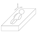
- the axis representing the direction from the right hand to the left hand of the subject is the X-axis
- the axis representing the direction from the back to the front of the subject is the Y-axis
- the subject is defined as the Z axis.
- the XY cross section is defined as an axial surface
- the YZ cross section is defined as a sagittal surface
- the ZX cross section is defined as a coronal surface. That is, the X-axis direction is a direction orthogonal to the sagittal plane (hereinafter, sagittal direction).
- the Y-axis direction is a direction orthogonal to the coronal plane (hereinafter, coronal direction). Further, the Z-axis direction is a direction orthogonal to the axial plane (hereinafter referred to as an axial direction).
- the slice plane of the image represents an axial plane
- the direction orthogonal to the slice plane (hereinafter, the slice direction) represents the axial direction.
- the method of taking the coordinate system is an example, and other definitions may be used.
- the modality for capturing a three-dimensional tomographic image may be an MRI apparatus, a three-dimensional ultrasonic imaging apparatus, a photoacoustic tomography apparatus, a PET / SPECT, an OCT apparatus, or the like.
- the first medical image and the second medical image may be any image as long as it is a three-dimensional tomographic image for which a difference image is generated. For example, they may be captured at the same time in different modality or different shooting modes. Further, for follow-up, images of the same patient may be taken at different dates and times with the same modality and the same position.
- the first medical image and the second medical image are three-dimensional medical images (three-dimensional tomographic images) configured as a set of two-dimensional tomographic images, and the position and orientation of each two-dimensional tomographic image are reference. It is assumed that it is stored in the data server 130 after being converted into a coordinate system (a coordinate system in space based on the subject). At this time, the first medical image and the second medical image represented in the reference coordinate system are input to the image processing device 100 according to the instruction of the user who operates the instruction unit 140.
- the image processing device 100 is a device that receives a processing request from the instruction unit 140, performs image processing, and outputs the processing result to the display unit 150, and functions as a terminal device for image interpretation operated by a user such as a doctor. To do. Specifically, based on an instruction from the user through the instruction unit 140, the first medical image and the second medical image to be image-processed are acquired as an image pair from the data server 130. Then, the alignment processing of these images is performed, a difference image is generated, and the difference image is output to the display unit 150.
- the image processing device 100 is composed of the components described below.
- the acquisition unit 101 acquires the information of the first medical image and the second medical image input to the image processing device 100.
- the conversion unit 102 converts the resolution of the first medical image and the second medical image into predetermined resolutions (hereinafter, processing resolutions), respectively.
- the alignment unit 103 performs alignment processing between the first medical image and the second medical image (hereinafter, the first converted image and the second converted image) after the resolution is converted, and the alignment process is performed between the images. Calculate the displacement field.
- the determination unit 104 determines the resolution of the difference image to be output (hereinafter, output resolution).
- the difference image generation unit 105 is a difference between the second deformed image obtained by deforming the second medical image so as to match the first medical image based on the acquired displacement field and the first medical image. Generate an image based on the output resolution.
- the projection image generation unit 106 generates a projection image (hereinafter referred to as a difference projection image) in which the brightness value of the difference image is projected two-dimensionally.
- the display control unit 107 controls to output the generated difference image, difference projection image, and the like to the display unit 150.
- the display unit 150 is composed of an arbitrary device such as an LCD or a CRT, and displays a medical image or the like for the doctor to interpret. Specifically, a cross-sectional image of a first medical image and a second medical image acquired from the image processing apparatus 100 is displayed. In addition, a cross-sectional image of the difference image generated by the image processing device 100 and a difference projection image are displayed.
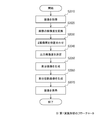
- FIG. 2 is a flowchart showing the entire processing procedure performed by the image processing device 100.
- step S2010 the acquisition unit 101 acquires the first medical image and the second medical image designated by the user from the data server 130 through the instruction unit 140. Then, the first medical image and the second medical image are output to the conversion unit 102, the difference image generation unit 105, and the display control unit 107.
- step S2020 the conversion unit 102 converts the first medical image and the second medical image into processing resolutions, and acquires the first converted image and the second converted image.
- the alignment between the images performed in the subsequent processing can be performed with high accuracy.
- the first converted image and the second converted image in which the pixel size is isometric are acquired. More specifically, for example, when the first image and the second image are CT images, the resolution in the slice plane (for example, sagittal direction and coronal direction) is higher than the resolution in the slice direction (axial direction). Therefore, a process of upsampling the pixels in the slice direction according to the resolution in the slice plane is performed.
- a known image processing method can be used for interpolation of the density value at the time of resolution conversion.
- the processing resolution is set to 1 mm in each of the three-dimensional axial directions so that the difference in details between the images can be calculated, and the pixel size is isotropicized by the resolution conversion of the first converted image and the second converted image. Get the converted image.
- the processing resolution does not have to be 1 mm as long as the difference in details between the images can be calculated sufficiently. Further, it does not necessarily have to be isotropic, and it is sufficient that the resolution can be converted to such an extent that the alignment between images performed in the subsequent processing can be performed with high accuracy. Further, when the resolution conversion processing is not necessary, such as when the resolutions of the first medical image and the second medical image are already the processing resolutions at the stage acquired in step S2010, the resolution conversion is not necessarily performed. Good. Then, the generated first converted image and the second converted image are output to the alignment unit 103.
- step S2030 the alignment unit 103 aligns the first converted image and the second converted image so that the pixels representing the same portion substantially match, and acquires a displacement field that associates the positions between the images. .. Then, the information of the displacement field which is the result of the alignment is output to the difference image generation unit 105.
- the alignment between images indicates a process of calculating a displacement field for displaced each pixel position of one image to correspond to the pixel position of the other image.
- the displacement field is created by displacing the pixel position of each image captured in the past compared to one image and making it correspond to the pixel position of one image. calculate. That is, assuming that the second medical image is an image captured in the past as compared with the first medical image in the present embodiment, the position of each pixel on the second converted image is displaced to obtain the first converted image.
- the displacement vector field at each pixel position is acquired by aligning with. That is, the generated displacement field is an image (second deformed image) in which the displacement vector at each pixel position of the first converted image is stored with reference to the first converted image, and is combined with the first converted image. It has the same resolution and the same number of pixels. Therefore, when the processing resolution is 1 mm isotropic, the displacement field is also an isotropic displacement vector field of 1 mm. As a result, the displacement field holds an amount of information in which the difference in details between the images can be calculated.
- the alignment is performed by a known image processing method. For example, it is obtained by deforming one of the images so that the image similarity between the images is high.
- a commonly used method such as Sum of Squared Difference (SSD), mutual information amount, and mutual correlation coefficient can be used.
- SSD Sum of Squared Difference
- known deformation models such as a deformation model based on a radial basis function such as Thin Plate Spline (TPS), a Free Form Deformation (FFD), and a Large Deformation Defeomorphic Metallic Mapping (LDDMM) can be used. ..
- TPS Thin Plate Spline
- FFD Free Form Deformation
- LDMM Large Deformation Defeomorphic Metallic Mapping
- step S2040 (Determine the output resolution)
- the determination unit 104 determines the output resolution based on the resolution of the first medical image and the processing resolution used in step S2020.
- the determined output resolution value is output to the difference image generation unit 105.
- the position of the image that is the reference for alignment (the first medical image in this embodiment) and the difference image of the two images are set for each pixel.
- the difference image is generated with the same resolution and the same number of pixels as the image (first medical image) that serves as a reference for alignment.
- a difference projection image obtained by two-dimensionally projecting a difference image in a direction parallel to the slice surface or a cross-sectional image obtained by cutting the difference image at an arbitrary cross section including a sagittal surface or a coronal surface, which is different from the slice surface (axial surface).
- the slice interval of the first image is coarse
- the slice interval of the difference image is also coarse.
- the resolution is sufficient when the cross-sectional image of the sliced surface of the difference image is displayed on the display unit, but when the difference projection image is displayed on the display unit, it is displayed at a coarse resolution in the slice direction. was there.
- the resolutions often do not always match in all axial directions when acquiring 3D tomographic images with various modality.
- the resolution in the slice direction (axial direction) is set to the resolution in the slice in-plane direction (for example, sagittal direction or coronal direction) in order to reduce the exposure dose and the amount of data. It is often coarser than that.
- the resolution in the slice plane at the output resolution is matched with the resolution of the first image so that the first image and the difference image can be displayed in association with each other.
- the resolution in the slice direction in the output resolution it is determined so that the differential projection image does not become coarse.
- the slice plane of a three-dimensional image is defined as the X-axis and the Y-axis (for example, the sagittal direction and the coronal direction) and the slice direction (axial direction) is defined as the Z-axis
- the X-axis of the three axes constituting the output resolution is defined.
- the Y-axis (in-slice plane) resolutions are determined to match the X-axis and Y-axis resolutions of the resolution of the first medical image.
- the resolution of the Z-axis (slice direction) is determined based on the resolution of the Z-axis of the first medical image and a predetermined resolution (hereinafter, the first resolution) in which the difference in details between the images can be calculated. To do.
- the higher (finer) resolution is the Z-axis output resolution (that is, the Z-axis of the difference image).
- the Z-axis output resolution is set to the same resolution as the first resolution.
- the Z-axis output resolution is set to the Z-axis resolution of the first medical image.
- the value of the processing resolution is adopted as the first resolution. That is, the upper limit of the output resolution in the slice direction is set as the processing resolution. Specifically, assuming that the processing resolution is 1 mm isotropic, 1 mm is used as the first resolution. In this way, by matching the upper limit value (first resolution) of the resolution in the slice direction of the output resolution with the processing resolution, the output resolution in the slice direction is the displacement obtained by the alignment process as described in step S2030. It also matches the resolution of the field. As described in step S2030, the displacement field is generated at a resolution (1 mm) at which the difference in details between the images can be calculated.
- the upper limit of the output resolution in the slice direction is not only set so that the size of each pixel of the differential projection image does not increase, but also the amount of information is set as a value that can express the difference in details between the images. It will be done.
- the upper limit value (maximum value) for the resolution value in the slice direction of the output resolution in this way, even when the slice interval of the first medical image is coarse (the resolution in the slice direction is coarse), the difference is obtained.
- the resolution in the slice direction of the projected image can be made finer.
- the resolution in the slice direction of the differential projection image can be made fine as it is. Therefore, as compared with the method of always generating a difference image at a predetermined resolution regardless of the resolution of the first medical image, a more appropriate resolution can be determined, so that a highly visible difference projection image can be generated.
- the value used as the first resolution is an example and is not limited to the above. That is, the first resolution does not have to match the value of the processing resolution, and may not be 1 mm. Desirably, it is a predetermined value of 0.5 mm or more and 2.0 mm or less. According to the above, the resolution can be appropriately set even when observing the time course of the bone portion of the subject, for example.
- the resolution of the first medical image in the slice direction is 5 mm
- the resolution of the first medical image is coarser than the processing resolution with respect to the slice direction, so the value of the output resolution in the slice direction is set to 1 mm.
- the resolution in the slice direction of the first medical image is 0.5 mm
- the resolution of the first medical image in the slice direction is finer than the processing resolution, so the value of the output resolution in the slice direction is set to 0.5 mm.
- the slice direction value of the output resolution may be based on three resolutions including the slice direction resolution of the second medical image. That is, the value of the output resolution in the slice direction is adjusted to a resolution obtained by correcting the resolution in the slice direction of the first medical image, which is the reference of the difference image, based on the resolution in the slice direction of the first resolution and the second medical image. You may decide to be. More specifically, it may be the minimum value (highest resolution) of these three resolutions. As a result, the slice direction value of the output resolution can be adjusted to the most informative, that is, fine resolution, of the slice direction resolution of the first medical image, the slice direction resolution of the second medical image, and the processing resolution. ..
- the value in the slice direction (axial direction) of the output resolution but also the value in the slice plane (in this example, the value in the X-axis (sagittal direction) and the value in the Y-axis (coronal direction)) of the first medical image. It may be calculated based on the resolution and the processing resolution. That is, the resolution in at least one axial direction among the three axial directions constituting the resolution of the difference image is determined based on the resolution of the first medical image and the predetermined first resolution.
- the output resolution in the slice direction is not the minimum value of the first medical image and the processing resolution (including a combination of a plurality of resolutions), but an intermediate value such as an average value thereof or an average value weighted to each resolution. May be.
- the output resolution in the slice direction is minimized even when both the first medical image and the second medical image are extremely coarse.
- the value can be set closer to the first medical image or the second medical image than in the case of the value. That is, it is possible to reduce the possibility of generating a difference image or a difference projection image having a fine resolution unnecessarily.
- the resolution of the original image to be differentiated is extremely coarse, so that the alignment itself is also coarse. Become. Therefore, even if the resolution of the displacement field obtained as a result of alignment is as fine as 1 mm, the amount of information contained therein is almost the same as that of the coarse displacement field, and the difference projection image obtained as a result is based on the coarse difference. It becomes. That is, when the output resolution in the slice direction is matched with the processing resolution (1 mm) which is the minimum value of the plurality of resolutions, a difference image or a difference projection image having an unnecessarily fine resolution is generated.
- the processing resolution (1 mm) which is the minimum value of the plurality of resolutions
- the output resolution in the slice direction can be set to a value closer to the first medical image or the second medical image than in the case of the minimum value. ..
- the displacement field due to alignment can be obtained only at a resolution of 1 mm. Therefore, the obtained difference projection image can be obtained only by the amount of information of the resolution of the displacement field (however, as described above, it is sufficient for calculating the difference in details between the images). That is, when the output resolution in the slice direction is matched with the resolution (0.1 mm) of the first medical image, which is the minimum value of the combination of a plurality of resolutions, a difference image or a difference projection image having an unnecessarily fine resolution is generated. To.
- the output resolution determination method can perform the above-mentioned normal process of setting the minimum value when a predetermined condition is satisfied, and set the average value only when the predetermined condition is not satisfied.
- a predetermined condition is set as the first condition
- the first condition is that the resolution in the slice direction of the first medical image is equal to or higher than the first threshold value (for example, 0.4 mm or higher) and the second condition. It is assumed that it is less than the threshold value (for example, less than 7 mm).
- the determination unit 104 sets the resolution of the difference image in the slice direction, the resolution of the first medical image, and the resolution of the second medical image.
- the highest (fine) resolution is determined.
- the resolution in the slice direction of the difference image is determined to be the average value of the resolution of the first medical image, the resolution of the second medical image, and the first resolution.
- step S2050 (Generate a difference image)
- the difference image generation unit 105 displaces each position on the second medical image to a position on the first medical image based on the displacement field acquired in step S2030.
- a difference image is generated by taking a difference value of pixels with the corresponding position on the first medical image.
- the difference image is generated with the output resolution determined in step S2030.
- the generated difference image is output to the projection image generation unit 106 and the display control unit 107.
- FIG. 3 shows an axial cross section 300 of the first medical image, an axial cross section 301 of the second medical image, and an axial cross section 302 of the difference image.
- 303 on the axial cross section 300 of the first medical image represents an abnormal portion
- 304 on the axial cross section 302 of the difference image represents a difference region corresponding to the abnormal portion 303.
- the difference region corresponding to the abnormal portion 303 is a difference value of the brightness of those regions because there is no abnormal portion in the region of the second medical image corresponding to the abnormal portion 303 existing in the first medical image. This is the area depicted.
- the images correspond to each other in pixel units. Therefore, for example, it is possible to easily display the corresponding positions between the images, such as fusion of images and the display of the position of the corresponding original abnormal portion 303 when the difference region 304 is specified.
- step S2060 (Generate differential projection image)
- the projection image generation unit 106 generates a difference projection image in which the brightness value of the difference image generated in step S2040 is projected two-dimensionally. Then, the generated difference projection image is output to the display control unit 107.
- a difference projection image a projection image obtained by projecting a difference image, which is a three-dimensional image, in parallel with the slice plane is generated.
- the slice direction coincides with the body axis direction (Z axis), so that the difference projection image is an image projected in a direction orthogonal to the body axis of the subject.
- a differential projection image projected in the front direction (colonal direction) of the subject is generated as a direction orthogonal to the body axis.
- a projection method for example, an image in which the average value of the maximum value and the minimum value of the brightness in the projection direction is calculated is generated.
- this is referred to as a MIP / MinIP image (maximum value projection / minimum value projection image).
- MIP Maximum Industry Projection
- MinIP Minimum Industry Projection
- the differential projection image includes a MIP image, a MinIP image, or an image in which a value based on both the maximum value and the minimum value of the pixel value on the projection line is projected when the three-dimensional image is projected in two dimensions.
- the resolution in the slice direction of the differential projection image is the output resolution determined in step S2030.
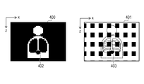
- FIG. 4 shows a coronal cross-sectional image 400 and a difference projection image 401 of the first medical image.
- 402 on the coronal cross-sectional image 400 of the first medical image represents an abnormal portion
- 403 on the differential projection image 401 represents a differential projection region in which a difference region corresponding to the abnormal portion 402 is projected. This corresponds to a region obtained by projecting a three-dimensional difference region including the difference region 304 on the slice image of FIG. 3 in the coronal direction.
- the slice interval of the first medical image is coarse (example: 5 mm)
- the resolution in the slice direction (Z axis in the figure) of the coronal cross-sectional image 400 is coarse.
- the difference projection image 401 is an image that retains the information amount of the difference in details whose resolution in the slice direction is the processing resolution (example: 1 mm), it does not become coarse in the slice direction. That is, since the slice interval of the first medical image is coarse, the abnormal portion 402 becomes coarse on the coronal cross section 400, but the difference projection area 403 on the difference projection image holds the amount of information of the difference in detail. Therefore, it is drawn in detail.
- step S2070 the display control unit 107 controls the display unit 150 to display the cross-sectional image of the difference image acquired from the difference image generation unit 105 and the difference projection image acquired from the projection image generation unit 106. Further, the display unit 150 is controlled to display the cross-sectional images of the first medical image and the second medical image.
- the process of displaying these images is not always necessary, and the generated difference image or projection difference image may be stored in a holding unit (not shown) or output to the data server 130. Further, it is not always necessary to generate the difference projection image, and the projection difference image may be generated by another device based on the difference image saved by the image processing device 100.
- the resolution in the slice direction can be generated with a fine resolution even if the slice interval of the original image is coarse. ..
- Non-Patent Document 1 when a projected image in which the brightness value of the difference image is projected parallel to the slice surface is generated as in Non-Patent Document 1, a projected image having a fine resolution in the slice direction can be obtained even if the slice interval of the original image is coarse. Can be generated.
- the upper limit value (first resolution) at the time of determining the value of the output resolution in the slice direction and the processing resolution are the same.
- the upper limit of the output resolution and the processing resolution do not necessarily have to match.
- the processing resolution may be a value close to the upper limit of the output resolution.
- the value in the vicinity is defined as a value within ⁇ 0.5 mm with respect to the target resolution. That is, it is a value including the first resolution based on the first resolution.
- the upper limit of the output resolution is a resolution (1 mm) in which the difference in details between the images can be calculated as described in step S2020.
- step S2020 the processing resolution for resolution conversion is set to 1.5 mm, which is a value near 1 mm.
- step S2030 the alignment is performed between the first converted image and the second converted image whose resolution has been converted to 1.5 mm.
- the alignment is performed at high speed without reducing the alignment accuracy as much as possible (without reducing the amount of information in the displacement field as much as possible) by aligning with the resolution in the vicinity thereof. be able to.
- step S2050 a difference image having an upper limit value of the output resolution of 1 mm is generated using a displacement field having a resolution of 1.5 mm, and a difference projection image based on the difference image is generated in step S2070.
- the difference projection image can be generated without reducing the amount of information in the slice direction so much. ..
- the processing resolution is coarser than the upper limit of the output resolution but is close to the value, the difference projection image can be produced at high speed without degrading the quality of the difference projection image generated in the first embodiment as much as possible. Can be output.
- the technique disclosed in the present specification can be implemented as, for example, a system, an apparatus, a method, a program, a recording medium (storage medium), or the like. Specifically, it may be applied to a system composed of a plurality of devices (for example, a host computer, an interface device, an imaging device, a web application, etc.), or it may be applied to a device composed of one device. good.
- a system composed of a plurality of devices (for example, a host computer, an interface device, an imaging device, a web application, etc.), or it may be applied to a device composed of one device. good.
- a recording medium (or storage medium) in which a software program code (computer program) that realizes the functions of the above-described embodiment is recorded is supplied to the system or device.
- the storage medium is a computer-readable storage medium.
- the computer or CPU or MPU
- the program code itself read from the recording medium realizes the function of the above-described embodiment, and the recording medium on which the program code is recorded constitutes the technique disclosed in the present specification.
Landscapes
- Engineering & Computer Science (AREA)
- Physics & Mathematics (AREA)
- Health & Medical Sciences (AREA)
- General Physics & Mathematics (AREA)
- Theoretical Computer Science (AREA)
- Medical Informatics (AREA)
- Life Sciences & Earth Sciences (AREA)
- Computer Vision & Pattern Recognition (AREA)
- General Health & Medical Sciences (AREA)
- Nuclear Medicine, Radiotherapy & Molecular Imaging (AREA)
- Radiology & Medical Imaging (AREA)
- Quality & Reliability (AREA)
- Biophysics (AREA)
- Surgery (AREA)
- Optics & Photonics (AREA)
- Pathology (AREA)
- Biomedical Technology (AREA)
- Heart & Thoracic Surgery (AREA)
- Molecular Biology (AREA)
- High Energy & Nuclear Physics (AREA)
- Animal Behavior & Ethology (AREA)
- Public Health (AREA)
- Veterinary Medicine (AREA)
- Apparatus For Radiation Diagnosis (AREA)
- Image Analysis (AREA)
- Image Processing (AREA)
Abstract
本明細書に開示の画像処理装置は、被検体を撮像して得られた3次元画像である第1の医用画像と第2の医用画像から3次元画像である差分画像を生成する画像処理装置であって、前記第1の医用画像と前記第2の医用画像を取得する取得手段と、前記差分画像の解像度を決定する決定手段と、前記決定手段が決定した解像度で前記差分画像を生成する差分画像生成手段と、を備え、前記決定手段は、前記差分画像の解像度を構成する3つの軸方向のうち少なくとも1軸方向の解像度を、前記第1の医用画像の解像度と、所定の第1の解像度とに基づいて決定することを特徴とする。
Description
本明細書の開示は、画像処理装置、画像処理方法及びプログラムに関する。
医療の分野において、種々のモダリティにより互いに異なる時刻に撮像して得られた2つの画像から生成される差分画像をユーザに提示することにより、病変等の経時変化を可視化する試みがなされている。
非特許文献1では、CT装置により撮像して得られた2つの3次元画像から生成した差分画像を2次元の断層画像として表示する技術が開示されている。また、差分画像の輝度値をスライス面と平行な方向(CTでは一般に被検体の体軸と直交する方向)に投影した2次元の投影画像を生成・表示する技術が開示されている。
SUMMARY
SUMMARY
R.Sakamoto,et.al,Temporal subtraction system for detecting bone metastasis using LDDMM : preliminary study,CARS2014.
しかし、非特許文献1の技術では、スライス間隔が粗い2つの3次元画像から差分画像を生成した場合には、差分画像のスライス間隔も粗くなる。その結果、差分画像の輝度値をスライス面と平行な方向に投影した投影画像を表示部に表示した場合に見づらいという課題があった。
上記課題に鑑み、本明細書の開示は、スライス面と平行な方向に投影した場合でも視認性の高い差分画像を生成することを目的とする。
なお、前記目的に限らず、後述する発明を実施するための形態に示す各構成により導かれる作用効果であって、従来の技術によっては得られない作用効果を奏することも本明細書の開示の他の目的の1つとして位置付けることができる。
本明細書に開示の画像処理装置は、被検体を撮像して得られた3次元画像である第1の医用画像と第2の医用画像から3次元画像である差分画像を生成する画像処理装置であって、前記第1の医用画像と前記第2の医用画像を取得する取得手段と、前記差分画像の解像度を決定する決定手段と、前記決定手段が決定した解像度で前記差分画像を生成する差分画像生成手段と、を備え、前記決定手段は、前記差分画像の解像度を構成する3つの軸方向のうち少なくとも1軸方向の解像度を、前記第1の医用画像の解像度と、所定の第1の解像度とに基づいて決定することを特徴とする。
本明細書の開示によれば、スライス面と平行な方向に投影した場合でも視認性の高い差分画像を生成することができる。
以下、添付図面に従って本明細書に開示の画像処理装置の好ましい実施形態について詳説する。ただし、この実施形態に記載されている構成要素はあくまで例示であり、本明細書に開示の画像処理装置の技術的範囲は、特許請求の範囲によって確定されるのであって、以下の個別の実施形態によって限定されるわけではない。また、本明細書の開示は下記実施形態に限定されるものではなく、本明細書の開示の趣旨に基づき種々の変形(各実施例の有機的な組合せを含む)が可能であり、それらを本明細書の開示の範囲から除外するものではない。即ち、後述する各実施例及びその変形例を組み合わせた構成も全て本明細書に開示の実施形態に含まれるものである。
<第1の実施形態>
本実施形態に係る画像処理装置は、互いに異なる時刻に撮像された2つの画像間で位置合わせを行い、差分画像を生成する装置である。本実施形態に係る画像処理装置は、2つの画像(原画像)のスライス間隔が粗い場合には、差分画像のスライス面に直交する方向の解像度(すなわち、差分画像のスライス間隔)を、所定の細かい解像度に合わせて生成することを特徴とする。
本実施形態に係る画像処理装置は、互いに異なる時刻に撮像された2つの画像間で位置合わせを行い、差分画像を生成する装置である。本実施形態に係る画像処理装置は、2つの画像(原画像)のスライス間隔が粗い場合には、差分画像のスライス面に直交する方向の解像度(すなわち、差分画像のスライス間隔)を、所定の細かい解像度に合わせて生成することを特徴とする。
以下、図1乃至図4を用いて、本実施形態の構成及び処理を説明する。
図1は、本実施形態に係る画像処理システムの構成を示す。同図に示すように、本実施形態における画像処理装置100は、ネットワーク120を介してデータサーバ130と接続されている。
データサーバ130は、複数の医用画像を保持している。以下の説明では、データサーバ130には、第1の医用画像および第2の医用画像として、異なる条件(異なるモダリティ、撮影モード、日時、体位等)で被検体を予め撮像して得られた複数の3次元断層画像が保持されているとする。本実施形態では、第1の医用画像と第2の医用画像はX線CT装置により撮像して得られた3次元断層画像(3次元医用画像)であるとして説明を行う。
なお、本明細書においては、図5に示すように、被検者の右手から左手への方向を表す軸をX軸、被検者の背面から正面への方向を表す軸をY軸、被検者の頭から足への方向を表す軸をZ軸として定義する。また、XY断面をアキシャル面、YZ断面をサジタル面、ZX断面をコロナル面と定義する。すなわち、X軸方向は、サジタル面に直交する方向(以下、サジタル方向)である。また、Y軸方向は、コロナル面に直交する方向(以下、コロナル方向)である。さらに、Z軸方向は、アキシャル面に直交する方向(以下、アキシャル方向)である。このとき、2次元スライス画像の集合として構成されるCT画像の場合は、画像のスライス面はアキシャル面を表し、スライス面に直交する方向(以下、スライス方向)はアキシャル方向を表す。なお、座標系の取り方は一例であり、これ以外の定義であってもよい。
なお、3次元断層画像を撮像するモダリティは、MRI装置、3次元超音波撮影装置、光音響トモグラフィ装置、PET/SPECT、OCT装置などであってもよい。さらに、第1の医用画像および第2の医用画像は、差分画像を生成する対象となる3次元断層画像であれば、いかなる画像であってもよい。例えば、異なるモダリティや異なる撮影モードで同時期に撮像されたものであってもよい。また、経過観察のために、同一患者を同一モダリティ、同一体位で異なる日時に撮像した画像であってもよい。なお、第1の医用画像および第2の医用画像は、2次元断層画像の集合として構成された3次元医用画像(3次元断層画像)であり、各2次元断層画像の位置および姿勢は、基準座標系(被検体を基準とした空間中の座標系)に変換した上でデータサーバ130に保持されているものとする。このとき、基準座標系で表現された第1の医用画像および第2の医用画像は、指示部140を操作するユーザの指示に応じて、画像処理装置100に入力される。
画像処理装置100は、指示部140からユーザによる処理の要求を受け付けて画像処理を行い、処理結果を表示部150へ出力する装置であり、医師等のユーザが操作する読影用の端末装置として機能する。具体的には、指示部140を通じたユーザからの指示に基づいて、データサーバ130から、画像処理対象となる第1の医用画像と第2の医用画像を画像対として取得する。そして、これらの画像の位置合わせ処理を行い、差分画像を生成して表示部150に出力する。画像処理装置100は、以下に説明する構成要素により構成されている。取得部101は、画像処理装置100へと入力される第1の医用画像および第2の医用画像の情報を取得する。変換部102は、第1の医用画像と第2の医用画像を予め決められた解像度(以下、処理解像度)に夫々解像度変換する。位置合わせ部103は、解像度変換された後の第1の医用画像と第2の医用画像(以下、第1の変換画像、第2の変換画像)の間の位置合わせ処理を行い、画像間の変位場を算出する。決定部104は、出力する差分画像の解像度(以下、出力解像度)を決定する。差分画像生成部105は、取得した変位場に基づいて第2の医用画像を第1の医用画像と一致させるように変形させた第2の変形画像と、第1の医用画像との間の差分画像を、出力解像度に基づいて生成する。投影画像生成部106は、差分画像の輝度値を2次元に投影した投影画像(以下、差分投影画像)を生成する。表示制御部107は、生成された差分画像や差分投影画像等を表示部150に出力する制御を行う。
表示部150は、LCDやCRT等の任意の機器により構成されており、医師が読影するために医用画像等の表示を行う。具体的には、画像処理装置100から取得した第1の医用画像と第2の医用画像の断面画像を表示する。また、画像処理装置100で生成された差分画像の断面画像、および差分投影画像を表示する。
図2は、画像処理装置100が行う全体の処理手順を示すフローチャートである。
(S2010)(画像を取得)
ステップS2010において、取得部101は、データサーバ130から、指示部140を通じてユーザが指定した、第1の医用画像および第2の医用画像を取得する。そして、第1の医用画像および第2の医用画像を、変換部102、差分画像生成部105、および表示制御部107へと出力する。
ステップS2010において、取得部101は、データサーバ130から、指示部140を通じてユーザが指定した、第1の医用画像および第2の医用画像を取得する。そして、第1の医用画像および第2の医用画像を、変換部102、差分画像生成部105、および表示制御部107へと出力する。
(S2020)(画像の解像度を変換)
ステップS2020において、変換部102は、第1の医用画像および第2の医用画像を処理解像度に解像度変換し、第1の変換画像および第2の変換画像を取得する。
ステップS2020において、変換部102は、第1の医用画像および第2の医用画像を処理解像度に解像度変換し、第1の変換画像および第2の変換画像を取得する。
例えば、差分画像の原画像となる第1の医用画像および第2の医用画像の画素サイズが非等方な場合に、後段の処理で行う画像間の位置合わせを高精度に実施できるように、画素サイズを等方化した第1の変換画像および第2の変換画像を取得する。より具体的には、例えば第1の画像と第2の画像がCT画像の場合には、スライス方向(アキシャル方向)の解像度に対してスライス面内(例えばサジタル方向、コロナル方向)の解像度が高いため、スライス面内の解像度に合わせてスライス方向の画素をアップサンプリングする処理を行う。なお、解像度変換時の濃度値の補間には公知の画像処理手法を用いることができる。
本実施形態では、画像間の細部の差分が算出可能なように処理解像度を3次元の各軸方向に1mmとし、解像度変換により画素サイズが等方化された第1の変換画像と第2の変換画像を取得する。なお、処理解像度は十分に画像間の細部の差分が算出可能な解像度であれば1mmでなくともよい。また、必ずしも等方化しなくてもよく、後段の処理で行う画像間の位置合わせを高精度に実施できる程度に解像度を変換できればよい。さらに、ステップS2010において取得された段階で第1の医用画像と第2の医用画像の解像度が既に処理解像度である場合等の解像度変換処理が必要ない場合には、必ずしも解像度変換をしなくてもよい。そして、生成された第1の変換画像および第2の変換画像を、位置合わせ部103へと出力する。
(S2030)(2画像間を位置合わせ)
ステップS2030において、位置合わせ部103は、第1の変換画像と第2の変換画像間で同一部位を表す画素が略一致するように位置合わせを行い、画像間の位置を対応付ける変位場を取得する。そして、位置合わせの結果である変位場の情報を、差分画像生成部105へと出力する。
ステップS2030において、位置合わせ部103は、第1の変換画像と第2の変換画像間で同一部位を表す画素が略一致するように位置合わせを行い、画像間の位置を対応付ける変位場を取得する。そして、位置合わせの結果である変位場の情報を、差分画像生成部105へと出力する。
本実施形態では、画像間の位置合わせとは、一方の画像の各画素位置を変位させて他方の画像の画素位置に対応させるための変位場を算出する処理を示している。
例えば、互いに異なる時刻に撮像された2つの画像がある場合、一方の画像に比べて過去に撮像された画像の各画素位置を変位させ、一方の画像の画素位置に対応させることにより変位場を算出する。すなわち、本実施形態において第2の医用画像が第1の医用画像に比べて過去に撮像された画像であるとすると、第2の変換画像上の各画素位置を変位させて第1の変換画像に位置合わせすることにより各画素位置における変位ベクトル場を取得する。つまり、生成される変位場は、第1の変換画像を基準として、第1の変換画像の各画素位置における変位ベクトルを格納した画像(第2の変形画像)であり、第1の変換画像と同じ解像度、同じ画素数となる。従って、処理解像度が1mm等方の場合は、変位場も1mmで等方化された変位ベクトル場となる。これにより、変位場は画像間の細部の差分が算出可能な情報量を保持するものとなる。
本実施形態において、位置合わせは公知の画像処理手法により行う。例えば、画像間の画像類似度が高くなるように一方の画像を変形させることにより求める。画像類似度としては、一般的に用いられているSum of Squared Difference(SSD)や相互情報量、相互相関係数などの公知の方法を用いることができる。また、画像の変形のモデルとしては、Thin Plate Spline(TPS)などの放射基底関数に基づく変形モデルやFree Form Deformation(FFD)、Large Deformation Diffeomorphic Metric Mapping(LDDMM)等の公知の変形モデルを利用できる。
(S2040)(出力解像度を決定)
ステップS2040において、決定部104は、出力解像度を、第1の医用画像の解像度とステップS2020において用いた処理解像度とに基づいて決定する。
ステップS2040において、決定部104は、出力解像度を、第1の医用画像の解像度とステップS2020において用いた処理解像度とに基づいて決定する。
そして、決定した出力解像度の値を、差分画像生成部105へと出力する。
ここで、決定部104が出力解像度を決定する処理の詳細について説明する。
2画像間の差分画像を生成する一般的な方法として、2つの画像のうち位置合わせの基準となる画像(本実施形態では第1の医用画像)と、差分画像とが、画素毎に位置が対応付けられた形で差分画像を生成する方法がある。このとき、差分画像は、位置合わせの基準となる画像(第1の医用画像)と同じ解像度、同じ画素数で生成される。これにより、例えば、第1の医用画像に含まれる2次元断層画像と差分画像に含まれる2次元断層画像の位置を対応付けて確認したい場合には、容易に対応付けて表示することができる。
しかしながら、差分画像をスライス面に平行な方向に2次元投影した差分投影画像や、スライス面(アキシャル面)とは異なる、サジタル面やコロナル面を含む任意の断面で差分画像を切断した断面画像を生成して表示する場合は以下の問題が生じる。
すなわち、第1の画像のスライス間隔が粗いと、差分画像のスライス間隔も粗くなる。これにより、差分画像のスライス面の断面画像を表示部に表示した場合には解像度が十分であるものの、差分投影画像を表示部に表示した場合にはスライス方向に粗い解像度で表示されるという問題があった。この問題は、種々のモダリティにより3次元断層画像を取得する場合に、全ての軸方向において解像度が必ずしも一致しないことが多いために生じる。例えば、X線CT装置の場合は、被ばく量の低減やデータ量削減のために、スライス方向(アキシャル方向)の解像度(スライス間隔)はスライス面内方向(例えばサジタル方向やコロナル方向)の解像度に比べて粗いことが多い。
そのため、本実施形態では、出力解像度におけるスライス面内の解像度に関しては、第1の画像と差分画像を対応付けて表示できるように、第1の画像の解像度に一致させる。一方、出力解像度におけるスライス方向の解像度に関しては、差分投影画像が粗くならないように決定する。例えば、3次元画像のスライス面がX軸とY軸(例えばサジタル方向とコロナル方向)、スライス方向(アキシャル方向)がZ軸と定義される場合、出力解像度を構成する3軸のうち、X軸とY軸(スライス面内)の解像度は、第1の医用画像の解像度のX軸とY軸の解像度に一致させるように決定する。一方、Z軸(スライス方向)の解像度は、第1の医用画像のZ軸の解像度と、画像間の細部の差分が算出可能な所定の解像度(以下、第1の解像度)とに基づいて決定する。
より具体的には、第1の医用画像のZ軸の解像度と第1の解像度の2つの解像度のうち、高い(細かい)方の解像度をZ軸の出力解像度(すなわち、差分画像のZ軸の解像度)として設定する。すなわち、第1の医用画像のZ軸の解像度が「第1の解像度より粗い」の場合は、Z軸の出力解像度を第1の解像度と同じ解像度に設定する。一方、第1の医用画像のZ軸の解像度が「第1の解像度と同じ、または、第1の解像度より細かい」の場合は、Z軸の出力解像度を第1の医用画像のZ軸の解像度と同じ解像度に設定する。換言すると、解像度が極力粗くならないように、差分画像の基準となる第1の医用画像のスライス方向の解像度を、細かい解像度である第1の解像度に基づいて補正した解像度になるように出力解像度を決定する。
また、本実施形態では、第1の解像度として処理解像度の値を採用する。つまり、スライス方向に関して出力解像度の上限値を処理解像度とする。具体的には、処理解像度が1mm等方であるとすると、第1の解像度として1mmを使用する。このように、出力解像度のスライス方向の解像度の上限値(第1の解像度)を処理解像度に一致させることにより、ステップS2030に記載した通り、スライス方向の出力解像度は位置合わせ処理によって得られた変位場の解像度とも一致する。ステップS2030に記載した通り変位場は画像間の細部の差分が算出可能な解像度(1mm)で生成されている。従って、スライス方向の出力解像度の上限値は、単に差分投影画像の各画素のサイズが大きくならないように設定されているだけではなく、情報量としても画像間の細部の差分を表現できる値として設定されていることになる。このように、出力解像度のスライス方向の解像度の値に上限値(最大値)を設けることにより、第1の医用画像のスライス間隔が粗い(スライス方向の解像度が粗い)場合であっても、差分投影画像のスライス方向における解像度を細かくできる。そして、元々第1の医用画像のスライス間隔が細かい(スライス方向の解像度が細かい)場合には、差分投影画像のスライス方向における解像度をそのまま細かくできる。そのため、第1の医用画像の解像度に関わらず常に所定の解像度で差分画像を生成する方法に比べ、より適切な解像度に決定できるため視認性の高い差分投影画像を生成できる。
なお、第1の解像度として用いる値は一例であって上記に限定されない。すなわち、第1の解像度は処理解像度の値と一致していなくてもよいし、1mmでなくてもよい。望ましくは、0.5mm以上かつ2.0mm以下の所定の値であるとよい。上記により、例えば被検体の骨部の経時変化を観察する場合でも、解像度を適切に設定することができる。
このとき、第1の医用画像のスライス方向の解像度が5mmの場合は、スライス方向に関して第1の医用画像の解像度が処理解像度よりも粗いため、出力解像度のスライス方向の値を1mmとする。一方、第1の医用画像のスライス方向の解像度が0.5mmの場合は、スライス方向に関して第1の医用画像の解像度が処理解像度よりも細かいため、出力解像度のスライス方向の値を0.5mmとする。
なお、出力解像度の決定方法は、上記に限られるものではない。例えば、出力解像度のスライス方向の値を、さらに第2の医用画像のスライス方向の解像度も含めた3つの解像度に基づくようにしてもよい。すなわち、出力解像度のスライス方向の値を、差分画像の基準となる第1の医用画像のスライス方向の解像度を第1の解像度と第2の医用画像のスライス方向の解像度に基づいて補正した解像度になるように決定してもよい。より具体的には、これら3つの解像度の最小値(最も高い解像度)としてもよい。これにより、出力解像度のスライス方向の値を、第1の医用画像のスライス方向の解像度、第2の医用画像のスライス方向の解像度、処理解像度のうち最も情報量の多い、すなわち細かい解像度に合わせられる。
また、出力解像度のスライス方向(アキシャル方向)の値に限らず、スライス面内(この例ではX軸(サジタル方向)の値やY軸(コロナル方向))の値も、第1の医用画像の解像度と処理解像度に基づいて算出するようにしてもよい。すなわち、差分画像の解像度を構成する3つの軸方向のうち少なくとも1軸方向の解像度を、第1の医用画像の解像度と、所定の第1の解像度とに基づいて決定する。
これにより、全ての軸方向の解像度が適切に細かい、視認性の高い差分画像および差分投影画像を生成することができる。
さらに、スライス方向の出力解像度を、第1の医用画像と処理解像度(を含む複数の解像度の組み合わせ)の最小値ではなく、それらの平均値や各解像度に重み付けした平均値などの中間的な値としてもよい。
例えば、第1の医用画像、第2の医用画像及び処理解像度の平均値をとることで、第1の医用画像、第2の医用画像がともに極端に粗い場合でも、スライス方向の出力解像度を最小値の場合よりも第1の医用画像や第2の医用画像に近い値に設定できる。すなわち、不要に解像度の細かい差分画像や差分投影画像を生成する可能性を低減できる。
より詳細には、第1の医用画像と第2の医用画像のスライス間隔がともに極端に粗い(例:10mm)場合、差分をとる元画像の解像度自体が極端に粗いため、位置合わせ自体も粗くなる。従って、位置合わせの結果得られた変位場の解像度が1mmのように細かくても、そこに含まれる情報量は粗い変位場とほぼ変わらなくなり、その結果得られる差分投影画像は粗い差分に基づくものとなる。つまり、スライス方向の出力解像度を複数の解像度の最小値である処理解像度(1mm)に一致させると、不要に解像度の細かい差分画像や差分投影画像が生成される。
しかし、このような場合でも、出力解像度を平均値などに決定することにより不要に解像度の細かい差分画像や差分投影画像を生成する可能性を低減できる。
また、第1の医用画像、第2の医用画像がともに極端に細かい場合でも、スライス方向の出力解像度を最小値の場合よりも第1の医用画像や第2の医用画像に近い値に設定できる。
より詳細には、第1の医用画像と第2の医用画像のスライス間隔がともに極端に細かい(例:0.1mm)場合、位置合わせによる変位場が1mmの解像度でしか得られない。そのため、得られる差分投影画像は変位場の解像度の情報量でしか得られない(但し、上述の通り画像間の細部の差分算出には充分である)。つまり、スライス方向の出力解像度を、複数の解像度の組み合わせの最小値である第1の医用画像の解像度(0.1mm)に一致させると、不要に解像度の細かい差分画像や差分投影画像が生成される。
しかし、このような場合でも、複数の解像度の組み合わせの平均値をとることにより不要に解像度の細かい差分画像や差分投影画像を生成する可能性を低減できる。
また、出力解像度の決定方法は、所定の条件を満たす場合は、最小値を設定する上記の通常の処理を行い、所定の条件を満たさない場合にのみ、平均値を設定するようにできる。より具体的には、所定の条件を第1の条件とし、第1の条件を、第1の医用画像のスライス方向の解像度が第1の閾値以上(例えば、0.4mm以上)かつ第2の閾値未満(例えば、7mm未満)であることとする。このとき、決定部104は例えば、第1の医用画像の解像度が第1の条件を満たす場合に、差分画像のスライス方向の解像度を、第1の医用画像の解像度、第2の医用画像の解像度及び第1の解像度のうち、最も高い(細かい)解像度に決定する。一方、第1の条件を満たさない場合には、差分画像のスライス方向の解像度を、第1の医用画像の解像度、第2の医用画像の解像度及び第1の解像度の平均値に決定する。
(S2050)(差分画像を生成)
ステップS2050において、差分画像生成部105は、ステップS2030で取得した変位場に基づいて、第2の医用画像上の各位置を第1の医用画像上の位置に変位させる。その後、第1の医用画像上の対応位置との間で、画素の差分値を取ることで差分画像を生成する。このとき、差分画像はステップS2030で決定した出力解像度で生成する。そして、生成された差分画像を投影画像生成部106および表示制御部107へと出力する。
ステップS2050において、差分画像生成部105は、ステップS2030で取得した変位場に基づいて、第2の医用画像上の各位置を第1の医用画像上の位置に変位させる。その後、第1の医用画像上の対応位置との間で、画素の差分値を取ることで差分画像を生成する。このとき、差分画像はステップS2030で決定した出力解像度で生成する。そして、生成された差分画像を投影画像生成部106および表示制御部107へと出力する。
図3には、第1の医用画像のアキシャル断面300、第2の医用画像のアキシャル断面301、差分画像のアキシャル断面302が示されている。また、第1の医用画像のアキシャル断面300上の303は異常部位を表し、差分画像のアキシャル断面302上の304は異常部位303に対応する差分領域を表す。異常部位303に対応する差分領域とは、第1の医用画像に存在する異常部位303に対応する第2の医用画像の領域には異常部位が存在しないため、それらの領域の輝度の差分値として描出された領域である。このとき、差分画像のアキシャル断面302の解像度は第1の医用画像のアキシャル断面の解像度と一致するため、画像同士が画素単位で対応付いている。そのため、例えば、画像同士の融合や、差分領域304を指定すると対応する元の異常部位303の位置が表示されるといった画像間での対応位置の表示を容易に行える。
(S2060)(差分投影画像を生成)
ステップS2060において、投影画像生成部106は、ステップS2040で生成した差分画像の輝度値を2次元に投影した差分投影画像を生成する。そして、生成された差分投影画像を表示制御部107へと出力する。
ステップS2060において、投影画像生成部106は、ステップS2040で生成した差分画像の輝度値を2次元に投影した差分投影画像を生成する。そして、生成された差分投影画像を表示制御部107へと出力する。
より具体的には、差分投影画像として、3次元画像である差分画像をスライス面に平行に投影した投影画像を生成する。差分画像の原画像がX線CT画像の場合、スライス方向は体軸方向(Z軸)に一致するため、差分投影画像は、被検体の体軸に直交する方向に投影された画像となる。例えば、体軸に直交する方向として、被検体の正面方向(コロナル方向)に投影した差分投影画像を生成する。これにより、被検体の撮像部位全体の差分画像の情報を容易に把握できる。投影方法としては、例えば、投影方向における輝度の最大値と最小値の平均値を算出した画像を生成する。以下ではこれを、MIP/MinIP画像(最大値投影/最小値投影画像)と称する。これにより、差分画像における正の差分値、負の差分値の双方を考慮した値を投影画像上に反映できる。また、投影方法はこの方法に限られるものではなく、最大値投影(MIP:Maximum Intensity Projection)であっても、最小値投影(MinIP:Minimum Intensity Projection)であってもよい。すなわち、差分投影画像は、MIP画像もしくはMinIP画像、もしくは3次元画像を2次元に投影する際に、投影線上の画素値の最大値と最小値の両方に基づく値を投影した画像を含む。このとき、差分投影画像のスライス方向の解像度は、ステップS2030で決定した出力解像度となる。
図4は、第1の医用画像のコロナル断面画像400と差分投影画像401を示している。また、第1の医用画像のコロナル断面画像400上の402は異常部位を表し、差分投影画像401上の403は異常部位402に対応する差分領域を投影した差分投影領域を表す。これは、図3のスライス画像上の差分領域304を含む3次元の差分領域を、コロナル方向に投影した領域に相当する。図4では、第1の医用画像のスライス間隔が粗い(例:5mm)ため、コロナル断面画像400のスライス方向(図示のZ軸)の解像度は粗くなっている。しかし、差分投影画像401は、スライス方向の解像度が処理解像度(例:1mm)である細部の差分の情報量を保持した画像となるため、スライス方向に粗くならない。すなわち、第1の医用画像のスライス間隔が粗いためコロナル断面400上では異常部位402は粗くなってしまうが、差分投影画像上の差分投影領域403は、細部の差分の情報量を保持しているため、細かく描出される。
(S2070)(画像を表示)
ステップS2070において、表示制御部107は、差分画像生成部105から取得した差分画像の断面画像と、投影画像生成部106から取得した差分投影画像を、表示部150に表示する制御を行う。また、第1の医用画像と第2の医用画像の断面画像を表示部150に表示する制御を行う。
ステップS2070において、表示制御部107は、差分画像生成部105から取得した差分画像の断面画像と、投影画像生成部106から取得した差分投影画像を、表示部150に表示する制御を行う。また、第1の医用画像と第2の医用画像の断面画像を表示部150に表示する制御を行う。
なお、これらの画像を表示する処理は必ずしも必要ではなく、生成した差分画像や投影差分画像を不図示の保持部に保存する構成や、データサーバ130に出力する構成であってもよい。また、差分投影画像の生成は必ずしも必要ではなく、画像処理装置100が保存した差分画像に基づいて、他の装置で投影差分画像を生成するようにしてもよい。
以上によって、画像処理装置100の処理が実施される。
本実施形態によれば、差分画像の輝度値をスライス面に平行に投影した投影画像を生成する場合に、原画像のスライス間隔が粗い場合でもスライス方向の解像度を細かい解像度で生成することができる。
これにより、非特許文献1のように差分画像の輝度値をスライス面に平行に投影した投影画像を生成する場合に、原画像のスライス間隔が粗い場合でもスライス方向に細かい解像度を有する投影画像を生成することができる。
(変形例)
第1の実施形態では、出力解像度のスライス方向の値を決定する際の上限値(第1の解像度)と処理解像度は一致していた。しかし、必ずしも出力解像度の上限値と処理解像度は一致させなくともよい。例えば、処理解像度は出力解像度の上限値に対して近傍の値であってもよい。ここで、本変形例では、近傍の値とは、対象とする解像度に対して±0.5mm以内の値であると定義する。すなわち、第1の解像度に基づいた、第1の解像度を含む値である。例えば、ステップS2040において、出力解像度の上限値は、ステップS2020に記載した通り、画像間の細部の差分が算出可能な解像度(1mm)とする。一方、ステップS2020において、解像度変換する処理解像度を、1mmの近傍の値である1.5mmとする。そして、ステップS2030において、1.5mmに解像度変換された第1の変換画像と第2の変換画像の間で位置合わせを行う。これにより、1mmに解像度変換した場合に対して、その近傍の解像度で位置合わせすることで、位置合わせ精度を極力落とさずに(変位場の情報量を極力落とさずに)位置合わせを高速に行うことができる。そして、ステップS2050において、1.5mmの解像度の変位場を用いて、出力解像度の上限値を1mmとする差分画像を生成し、ステップS2070でその差分画像に基づく差分投影画像を生成する。このとき、差分画像を生成する際に用いた変位場は、1mmの場合に比べ情報量があまり落ちていないため、差分投影画像を、スライス方向の情報量をあまり落とさずに生成することができる。このように、処理解像度が出力解像度の上限値より粗くとも近傍の値であれば、第1の実施形態で生成される差分投影画像に対して極力品質を落とさずに、差分投影画像を高速に出力することができる。
第1の実施形態では、出力解像度のスライス方向の値を決定する際の上限値(第1の解像度)と処理解像度は一致していた。しかし、必ずしも出力解像度の上限値と処理解像度は一致させなくともよい。例えば、処理解像度は出力解像度の上限値に対して近傍の値であってもよい。ここで、本変形例では、近傍の値とは、対象とする解像度に対して±0.5mm以内の値であると定義する。すなわち、第1の解像度に基づいた、第1の解像度を含む値である。例えば、ステップS2040において、出力解像度の上限値は、ステップS2020に記載した通り、画像間の細部の差分が算出可能な解像度(1mm)とする。一方、ステップS2020において、解像度変換する処理解像度を、1mmの近傍の値である1.5mmとする。そして、ステップS2030において、1.5mmに解像度変換された第1の変換画像と第2の変換画像の間で位置合わせを行う。これにより、1mmに解像度変換した場合に対して、その近傍の解像度で位置合わせすることで、位置合わせ精度を極力落とさずに(変位場の情報量を極力落とさずに)位置合わせを高速に行うことができる。そして、ステップS2050において、1.5mmの解像度の変位場を用いて、出力解像度の上限値を1mmとする差分画像を生成し、ステップS2070でその差分画像に基づく差分投影画像を生成する。このとき、差分画像を生成する際に用いた変位場は、1mmの場合に比べ情報量があまり落ちていないため、差分投影画像を、スライス方向の情報量をあまり落とさずに生成することができる。このように、処理解像度が出力解像度の上限値より粗くとも近傍の値であれば、第1の実施形態で生成される差分投影画像に対して極力品質を落とさずに、差分投影画像を高速に出力することができる。
<その他の実施形態>
また、本明細書に開示の技術は例えば、システム、装置、方法、プログラム若しくは記録媒体(記憶媒体)等としての実施態様をとることが可能である。具体的には、複数の機器(例えば、ホストコンピュータ、インターフェイス機器、撮像装置、webアプリケーション等)から構成されるシステムに適用しても良いし、また、1つの機器からなる装置に適用しても良い。
また、本明細書に開示の技術は例えば、システム、装置、方法、プログラム若しくは記録媒体(記憶媒体)等としての実施態様をとることが可能である。具体的には、複数の機器(例えば、ホストコンピュータ、インターフェイス機器、撮像装置、webアプリケーション等)から構成されるシステムに適用しても良いし、また、1つの機器からなる装置に適用しても良い。
また、本明細書に開示の技術の目的は、以下のようにすることによって達成されることはいうまでもない。すなわち、前述した実施形態の機能を実現するソフトウェアのプログラムコード(コンピュータプログラム)を記録した記録媒体(または記憶媒体)を、システムあるいは装置に供給する。係る記憶媒体は言うまでもなく、コンピュータ読み取り可能な記憶媒体である。そして、そのシステムあるいは装置のコンピュータ(またはCPUやMPU)が記録媒体に格納されたプログラムコードを読み出し実行する。この場合、記録媒体から読み出されたプログラムコード自体が前述した実施形態の機能を実現することになり、そのプログラムコードを記録した記録媒体は本明細書に開示の技術を構成することになる。
本発明は上記実施の形態に制限されるものではなく、本発明の精神及び範囲から離脱することなく、様々な変更及び変形が可能である。従って、本発明の範囲を公にするために以下の請求項を添付する。
本願は、2019年4月10日提出の日本国特許出願特願2019-075075を基礎として優先権を主張するものであり、その記載内容の全てをここに援用する。
Claims (19)
- 被検体を撮像して得られた3次元画像である第1の医用画像と第2の医用画像から3次元画像である差分画像を生成する画像処理装置であって、
前記第1の医用画像と前記第2の医用画像を取得する取得手段と、
前記差分画像の解像度を決定する決定手段と、
前記決定手段が決定した解像度で前記差分画像を生成する差分画像生成手段と、
を備え、
前記決定手段は、前記差分画像の解像度を構成する3つの軸方向のうち少なくとも1軸方向の解像度を、前記第1の医用画像の解像度と、所定の第1の解像度とに基づいて決定することを特徴とする画像処理装置。 - 前記3次元画像は、2次元スライス画像の集合として構成された画像であり、
前記決定手段は、前記差分画像のスライス面に直交するスライス方向の解像度を、前記第1の医用画像の前記スライス方向の解像度と前記第1の解像度に基づいて決定することを特徴とする請求項1に記載の画像処理装置。 - 前記決定手段は、前記差分画像の前記スライス方向の解像度を、前記第1の医用画像の前記スライス方向の解像度と前記第1の解像度のうち、高い方の解像度に基づいて決定することを特徴とする請求項2に記載の画像処理装置。
- 前記決定手段は、前記差分画像の前記スライス方向の解像度を、前記第1の医用画像の前記スライス方向の解像度、前記第2の医用画像の前記スライス方向の解像度、及び前記第1の解像度のうち、最も高い解像度に基づいて決定することを特徴とする請求項2に記載の画像処理装置。
- 前記決定手段は、前記差分画像の前記スライス方向の解像度を、前記第1の医用画像の前記スライス方向の解像度と前記第1の解像度の平均値に基づいて決定することを特徴とする請求項2に記載の画像処理装置。
- 前記決定手段は、前記差分画像の前記スライス方向の解像度を、前記第1の医用画像の前記スライス方向の解像度、前記第2の医用画像の前記スライス方向の解像度、及び前記第1の解像度の平均値に基づいて決定することを特徴とする請求項2に記載の画像処理装置。
- 前記決定手段は、前記差分画像のスライス面内の解像度を、前記第1の医用画像のスライス面内の解像度に基づいて決定することを特徴とする請求項2乃至6のいずれか1項に記載の画像処理装置。
- 前記決定手段は、前記差分画像のスライス面内の解像度を、前記第1の医用画像のスライス面内の解像度に一致させることを特徴とする請求項7に記載の画像処理装置。
- 前記第1の画像と前記第2の画像を、前記第1の解像度またはその近傍の解像度に夫々変換したうえで当該画像間の位置合わせ処理を施す位置合わせ手段をさらに備え、
前記生成手段は、前記位置合わせ処理の結果に基づいて前記差分画像を生成することを特徴とする、請求項1に記載の画像処理装置。 - 前記決定手段は、前記第1の医用画像の解像度が第1の条件を満たす場合に、前記差分画像の解像度を、前記第1の医用画像の解像度、前記第2の医用画像の解像度及び前記第1の解像度のうち、最も高い解像度に基づいて決定し、且つ前記第1の条件を満たさない場合に、前記差分画像の方向の解像度を、前記第1の医用画像の解像度、前記第2の医用画像の解像度及び前記第1の解像度の平均値に基づいて決定することを特徴とする請求項1乃至9のいずれか1項に記載の画像処理装置。
- 前記第1の条件は、前記第1の医用画像の解像度が第1の閾値以上かつ、前記第1の閾値よりも高い第2の閾値未満であることを特徴とする請求項10に記載の画像処理装置。
- 前記決定手段は、前記差分画像の解像度を構成する3つの軸方向のうち少なくとも1軸方向の解像度を、前記第1の医用画像の解像度を所定の第1の解像度に基づいて補正した解像度に決定し、
前記差分画像生成手段は、前記決定手段が決定した解像度で前記第1の医用画像を基準にして前記差分画像を生成することを特徴とする請求項1乃至11のいずれか1項に記載の画像処理装置。 - 前記第1の医用画像と前記第2の医用画像の解像度を前記第1の解像度に基づいた値に変換して得られる第1の変換画像と第2の変換画像を位置合わせする位置合わせ手段をさらに備え、
前記生成手段は、前記位置合わせ処理の結果に基づいて前記差分画像を生成することを特徴とする請求項1乃至12のいずれか1項に記載の画像処理装置。 - 前記差分画像を前記スライス面に平行な方向に投影した投影画像を生成する投影画像生成手段をさらに備えることを特徴とする請求項1乃至13のいずれか1項に記載の画像処理装置。
- 前記投影画像は、MIP画像もしくはMinIP画像、もしくは3次元画像を2次元に投影する際に、投影線上の画素値の最大値と最小値の両方に基づく値を投影した画像を含むことを特徴とする請求項14に記載の画像処理装置。
- 前記第1の医用画像と前記第2の医用画像は互いに異なる時刻に撮像された画像であることを特徴とする請求項1乃至15のいずれか1項に記載の画像処理装置。
- 前記第1の解像度は、0.5mm以上かつ2.0mm以下の所定の値であることを特徴とする請求項1乃至16のいずれか1項に記載の画像処理装置。
- 被検体を撮像して得られた3次元医用画像である第1の医用画像と第2の医用画像から3次元の差分画像を生成する画像処理方法であって、
前記第1の医用画像と前記第2の医用画像を取得する取得工程と、
前記差分画像の解像度を決定する決定工程と、
前記決定工程において決定した解像度で前記差分画像を生成する差分画像生成工程と、を備え、
前記決定工程において、前記差分画像の解像度を構成する3つの軸方向のうち少なくとも1軸方向の解像度を、前記第1の医用画像の解像度と、所定の第1の解像度とに基づいて決定することを特徴とする画像処理方法。 - 請求項1乃至17のいずれか1項に記載の画像処理装置の各手段をコンピュータに実行させることを特徴とするプログラム。
Priority Applications (1)
| Application Number | Priority Date | Filing Date | Title |
|---|---|---|---|
| US17/497,721 US12169884B2 (en) | 2019-04-10 | 2021-10-08 | Image processing apparatus for generating a highly visible three-dimensional image from two medical images |
Applications Claiming Priority (2)
| Application Number | Priority Date | Filing Date | Title |
|---|---|---|---|
| JP2019-075075 | 2019-04-10 | ||
| JP2019075075A JP7387280B2 (ja) | 2019-04-10 | 2019-04-10 | 画像処理装置、画像処理方法及びプログラム |
Related Child Applications (1)
| Application Number | Title | Priority Date | Filing Date |
|---|---|---|---|
| US17/497,721 Continuation US12169884B2 (en) | 2019-04-10 | 2021-10-08 | Image processing apparatus for generating a highly visible three-dimensional image from two medical images |
Publications (1)
| Publication Number | Publication Date |
|---|---|
| WO2020209013A1 true WO2020209013A1 (ja) | 2020-10-15 |
Family
ID=72751793
Family Applications (1)
| Application Number | Title | Priority Date | Filing Date |
|---|---|---|---|
| PCT/JP2020/011469 Ceased WO2020209013A1 (ja) | 2019-04-10 | 2020-03-16 | 画像処理装置、画像処理方法及びプログラム |
Country Status (3)
| Country | Link |
|---|---|
| US (1) | US12169884B2 (ja) |
| JP (1) | JP7387280B2 (ja) |
| WO (1) | WO2020209013A1 (ja) |
Families Citing this family (1)
| Publication number | Priority date | Publication date | Assignee | Title |
|---|---|---|---|---|
| JP7451098B2 (ja) * | 2019-06-26 | 2024-03-18 | キヤノン株式会社 | 画像処理装置、画像処理方法及びプログラム |
Citations (3)
| Publication number | Priority date | Publication date | Assignee | Title |
|---|---|---|---|---|
| JP2005136594A (ja) * | 2003-10-29 | 2005-05-26 | Canon Inc | 画像処理装置及びその制御方法 |
| WO2018043575A1 (ja) * | 2016-08-31 | 2018-03-08 | キヤノン株式会社 | 画像処理装置、画像処理方法およびプログラム |
| JP2019046057A (ja) * | 2017-08-31 | 2019-03-22 | キヤノン株式会社 | 画像処理装置、画像処理方法およびプログラム |
Family Cites Families (7)
| Publication number | Priority date | Publication date | Assignee | Title |
|---|---|---|---|---|
| US8045770B2 (en) * | 2003-03-24 | 2011-10-25 | Cornell Research Foundation, Inc. | System and method for three-dimensional image rendering and analysis |
| WO2010073251A2 (en) * | 2008-12-25 | 2010-07-01 | Medic Vision - Brain Technologies Ltd. | Denoising medical images |
| US8594401B2 (en) * | 2010-03-30 | 2013-11-26 | The Johns Hopkins University | Automated characterization of time-dependent tissue change |
| JP5612371B2 (ja) * | 2010-06-11 | 2014-10-22 | 富士フイルム株式会社 | 画像位置合わせ装置および方法並びにプログラム |
| JP7039182B2 (ja) | 2017-05-24 | 2022-03-22 | キヤノンメディカルシステムズ株式会社 | 医用画像診断装置及び医用画像処理装置 |
| JP6772123B2 (ja) | 2017-12-27 | 2020-10-21 | キヤノン株式会社 | 画像処理装置、画像処理方法、画像処理システムおよびプログラム |
| JP7451098B2 (ja) * | 2019-06-26 | 2024-03-18 | キヤノン株式会社 | 画像処理装置、画像処理方法及びプログラム |
-
2019
- 2019-04-10 JP JP2019075075A patent/JP7387280B2/ja active Active
-
2020
- 2020-03-16 WO PCT/JP2020/011469 patent/WO2020209013A1/ja not_active Ceased
-
2021
- 2021-10-08 US US17/497,721 patent/US12169884B2/en active Active
Patent Citations (3)
| Publication number | Priority date | Publication date | Assignee | Title |
|---|---|---|---|---|
| JP2005136594A (ja) * | 2003-10-29 | 2005-05-26 | Canon Inc | 画像処理装置及びその制御方法 |
| WO2018043575A1 (ja) * | 2016-08-31 | 2018-03-08 | キヤノン株式会社 | 画像処理装置、画像処理方法およびプログラム |
| JP2019046057A (ja) * | 2017-08-31 | 2019-03-22 | キヤノン株式会社 | 画像処理装置、画像処理方法およびプログラム |
Also Published As
| Publication number | Publication date |
|---|---|
| US20220028134A1 (en) | 2022-01-27 |
| US12169884B2 (en) | 2024-12-17 |
| JP2020171481A (ja) | 2020-10-22 |
| JP7387280B2 (ja) | 2023-11-28 |
Similar Documents
| Publication | Publication Date | Title |
|---|---|---|
| US20190355174A1 (en) | Information processing apparatus, information processing system, information processing method, and computer-readable recording medium | |
| JP5526148B2 (ja) | 医療用画像のビューを生成する画像処理システム及び方法 | |
| US7620229B2 (en) | Method and apparatus for aiding image interpretation and computer-readable recording medium storing program therefor | |
| JPH08131403A (ja) | 医用画像処理装置 | |
| JP2017531228A (ja) | ボリューム画像への顔テクスチャのマッピング | |
| JP7809738B2 (ja) | 画像処理装置、画像処理方法及びプログラム | |
| CN111063424B (zh) | 一种椎间盘数据处理方法、装置、电子设备及存储介质 | |
| JP6995535B2 (ja) | 画像処理装置、画像処理方法およびプログラム | |
| US20260120301A1 (en) | Combining angiographic information with fluoroscopic images | |
| US20020154800A1 (en) | Image processing apparatus, image processing system, image processing method and storage medium | |
| JP2006000127A (ja) | 画像処理方法および装置並びにプログラム | |
| JP7824365B2 (ja) | 画像処理装置、画像処理方法、画像処理システム及びプログラム | |
| JP2017225835A (ja) | 画像処理装置 | |
| JP7387280B2 (ja) | 画像処理装置、画像処理方法及びプログラム | |
| EP3695380B1 (en) | Hypersurface reconstruction of microscope view | |
| JP6643433B2 (ja) | 読影レポート作成のための支援装置およびその制御方法 | |
| US10074198B2 (en) | Methods and apparatuses for image processing and display | |
| US20120007851A1 (en) | Method for display of images utilizing curved planar reformation techniques | |
| JP2019093288A (ja) | 画像処理装置及びプログラム | |
| JP2006247293A (ja) | 画像処理方法および画像処理装置ならびにプログラム | |
| JP6202960B2 (ja) | 画像処理装置、画像処理方法およびプログラム | |
| Almukhtar | Three dimensional study to quantify the relationship between facial hard and soft tissue movement as a result of orthognathic surgery | |
| Matsopoulos et al. | Image registration based on lifting process: an application to digital subtraction radiography | |
| JP2012147901A (ja) | 画像表示装置、その制御方法及びコンピュータプログラム |
Legal Events
| Date | Code | Title | Description |
|---|---|---|---|
| 121 | Ep: the epo has been informed by wipo that ep was designated in this application |
Ref document number: 20786702 Country of ref document: EP Kind code of ref document: A1 |
|
| NENP | Non-entry into the national phase |
Ref country code: DE |
|
| 122 | Ep: pct application non-entry in european phase |
Ref document number: 20786702 Country of ref document: EP Kind code of ref document: A1 |