WO2020203893A1 - 生体データ測定装置、生体データ測定方法及びプログラム - Google Patents
生体データ測定装置、生体データ測定方法及びプログラム Download PDFInfo
- Publication number
- WO2020203893A1 WO2020203893A1 PCT/JP2020/014328 JP2020014328W WO2020203893A1 WO 2020203893 A1 WO2020203893 A1 WO 2020203893A1 JP 2020014328 W JP2020014328 W JP 2020014328W WO 2020203893 A1 WO2020203893 A1 WO 2020203893A1
- Authority
- WO
- WIPO (PCT)
- Prior art keywords
- user
- electrode
- measurement
- inclination
- electrode portion
- Prior art date
- Legal status (The legal status is an assumption and is not a legal conclusion. Google has not performed a legal analysis and makes no representation as to the accuracy of the status listed.)
- Ceased
Links
Images


Classifications
-
- A—HUMAN NECESSITIES
- A61—MEDICAL OR VETERINARY SCIENCE; HYGIENE
- A61B—DIAGNOSIS; SURGERY; IDENTIFICATION
- A61B5/00—Measuring for diagnostic purposes; Identification of persons
- A61B5/05—Detecting, measuring or recording for diagnosis by means of electric currents or magnetic fields; Measuring using microwaves or radio waves
- A61B5/053—Measuring electrical impedance or conductance of a portion of the body
- A61B5/0537—Measuring body composition by impedance, e.g. tissue hydration or fat content
-
- A—HUMAN NECESSITIES
- A61—MEDICAL OR VETERINARY SCIENCE; HYGIENE
- A61B—DIAGNOSIS; SURGERY; IDENTIFICATION
- A61B5/00—Measuring for diagnostic purposes; Identification of persons
- A61B5/103—Measuring devices for testing the shape, pattern, colour, size or movement of the body or parts thereof, for diagnostic purposes
- A61B5/11—Measuring movement of the entire body or parts thereof, e.g. head or hand tremor or mobility of a limb
- A61B5/1116—Determining posture transitions
-
- A—HUMAN NECESSITIES
- A61—MEDICAL OR VETERINARY SCIENCE; HYGIENE
- A61B—DIAGNOSIS; SURGERY; IDENTIFICATION
- A61B5/00—Measuring for diagnostic purposes; Identification of persons
- A61B5/24—Detecting, measuring or recording bioelectric or biomagnetic signals of the body or parts thereof
- A61B5/25—Bioelectric electrodes therefor
- A61B5/26—Bioelectric electrodes therefor maintaining contact between the body and the electrodes by the action of the subjects, e.g. by placing the body on the electrodes or by grasping the electrodes
-
- A—HUMAN NECESSITIES
- A61—MEDICAL OR VETERINARY SCIENCE; HYGIENE
- A61B—DIAGNOSIS; SURGERY; IDENTIFICATION
- A61B5/00—Measuring for diagnostic purposes; Identification of persons
- A61B5/48—Other medical applications
- A61B5/4869—Determining body composition
- A61B5/4872—Body fat
-
- A—HUMAN NECESSITIES
- A61—MEDICAL OR VETERINARY SCIENCE; HYGIENE
- A61B—DIAGNOSIS; SURGERY; IDENTIFICATION
- A61B5/00—Measuring for diagnostic purposes; Identification of persons
- A61B5/68—Arrangements of detecting, measuring or recording means, e.g. sensors, in relation to patient
- A61B5/6801—Arrangements of detecting, measuring or recording means, e.g. sensors, in relation to patient specially adapted to be attached to or worn on the body surface
- A61B5/6813—Specially adapted to be attached to a specific body part
- A61B5/6825—Hand
-
- A—HUMAN NECESSITIES
- A61—MEDICAL OR VETERINARY SCIENCE; HYGIENE
- A61B—DIAGNOSIS; SURGERY; IDENTIFICATION
- A61B5/00—Measuring for diagnostic purposes; Identification of persons
- A61B5/68—Arrangements of detecting, measuring or recording means, e.g. sensors, in relation to patient
- A61B5/6801—Arrangements of detecting, measuring or recording means, e.g. sensors, in relation to patient specially adapted to be attached to or worn on the body surface
- A61B5/6813—Specially adapted to be attached to a specific body part
- A61B5/6829—Foot or ankle
-
- A—HUMAN NECESSITIES
- A61—MEDICAL OR VETERINARY SCIENCE; HYGIENE
- A61B—DIAGNOSIS; SURGERY; IDENTIFICATION
- A61B2560/00—Constructional details of operational features of apparatus; Accessories for medical measuring apparatus
- A61B2560/04—Constructional details of apparatus
- A61B2560/0406—Constructional details of apparatus specially shaped apparatus housings
-
- A—HUMAN NECESSITIES
- A61—MEDICAL OR VETERINARY SCIENCE; HYGIENE
- A61B—DIAGNOSIS; SURGERY; IDENTIFICATION
- A61B2560/00—Constructional details of operational features of apparatus; Accessories for medical measuring apparatus
- A61B2560/04—Constructional details of apparatus
- A61B2560/0462—Apparatus with built-in sensors
- A61B2560/0468—Built-in electrodes
-
- A—HUMAN NECESSITIES
- A61—MEDICAL OR VETERINARY SCIENCE; HYGIENE
- A61B—DIAGNOSIS; SURGERY; IDENTIFICATION
- A61B2562/00—Details of sensors; Constructional details of sensor housings or probes; Accessories for sensors
- A61B2562/02—Details of sensors specially adapted for in-vivo measurements
- A61B2562/0219—Inertial sensors, e.g. accelerometers, gyroscopes, tilt switches
Definitions
- the present invention relates to a biometric data measuring device for measuring biometric data of a user, a biometric data measuring method, and a program.
- JP5493198B discloses a body composition meter of a type in which a user holds a grip electrode by hand as a biological data measuring device.
- a biological data measuring device In this type of body composition meter, when the user holds the grip electrode with his / her hand, an electric current is passed from the hand and biological data such as impedance is measured to obtain a value related to the user's body composition, for example, body fat percentage.
- the grip electrode is not properly gripped, such as by changing the position where the user grips the grip electrode for each measurement, the biometric data measured via the grip electrode fluctuates, so that the user's body composition Cannot be calculated accurately.
- the body composition meter disclosed in JP5493198B determines whether or not the user is properly gripping the grip electrode, and measures the user's biometric data only when it is determined that the user is properly gripping the grip electrode. It is configured as follows.
- the biological data measured by passing an electric current from the hand changes according to the contraction rate of muscles, fluctuations in body water, and the like.
- the contraction rate of muscles, body water, and the like fluctuate according to the posture of the user. Therefore, in the above-mentioned body composition meter, even when the user holds the grip electrode properly, there is a problem that the value related to the user's body composition cannot be accurately obtained depending on the posture at the time of measurement. is there.
- An object of the present invention is to provide a biological data measuring device capable of accurately obtaining a value related to a user's body composition regardless of the posture of the user when measuring biological data.
- the biometric data measuring device includes an electrode for energization and an electrode for measurement that are spaced apart from each other, and an electrode portion that can be fixed to the upper limbs of the user and the user using the electrode portion.
- the biological information measuring means for measuring the biological information of the above, the tilt detecting means for detecting the inclination of the electrode portion, and the measurement result by the biological information measuring means are corrected according to the inclination of the electrode portion detected by the tilt detecting means. It is characterized in that it is provided with a correction means for performing.
- the biological information measured by passing an electric current from the hand can be corrected according to the posture of the user, so that the value related to the body composition of the user can be corrected regardless of the posture of the user. , Can be calculated more accurately.
- FIG. 1 is a diagram showing the appearance of a body composition meter to which the biological data measuring device according to the first embodiment of the present invention is applied.
- FIG. 2A is a diagram showing the appearance of a hand grip included in the biometric data measuring device according to the first embodiment.
- FIG. 2B is a diagram showing the appearance of the hand grip included in the biometric data measuring device according to the first embodiment.
- FIG. 2C is a diagram showing the appearance of the hand grip included in the biometric data measuring device according to the first embodiment.
- FIG. 3A is a diagram illustrating a usage state of the hand grip.
- FIG. 3B is a diagram illustrating a usage state of the hand grip.
- FIG. 4 is a block diagram showing an example of the functional configuration of the body composition meter of the first embodiment.
- FIG. 5A is a plan view of the acceleration sensor included in the handgrip.
- FIG. 5B is a side view of the acceleration sensor included in the handgrip.
- FIG. 5C is a diagram illustrating an arrangement example of an acceleration sensor included in the handgrip.
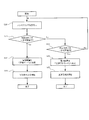
- FIG. 6 is a flowchart showing an example of a processing procedure related to the body composition measurement process in the first embodiment.
- FIG. 7 is a diagram illustrating a posture (normal posture) recommended when measuring the bioimpedance of a user using the body composition meter of the first embodiment.
- FIG. 8A is a diagram illustrating an inappropriate posture (abnormal posture) when measuring the bioimpedance of a user using the body composition meter of the first embodiment.
- FIG. 8B is a diagram for explaining an inappropriate posture (abnormal posture) when measuring the bioimpedance of the user using the body composition meter of the first embodiment.
- FIG. 9 is a diagram showing an example of an inappropriate posture (abnormal posture) when measuring the bioimpedance of a user using the body composition meter of the first embodiment.
- FIG. 10 is a diagram showing an example of an inappropriate posture (abnormal posture) when measuring the bioimpedance of a user using the body composition meter of the first embodiment.
- FIG. 11A is a diagram illustrating a handgrip according to the second embodiment.
- FIG. 11B is a diagram illustrating a handgrip according to the second embodiment.
- FIG. 11C is a diagram illustrating a handgrip according to the second embodiment.
- FIG. 11D is a diagram illustrating a handgrip according to the second embodiment.
- FIG. 12 is a block diagram showing an example of the functional configuration of the body composition meter of the second embodiment.
- FIG. 13 is a flowchart showing an example of a processing procedure related to the mode switching process in the second embodiment.
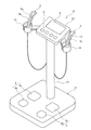
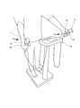
- FIG. 1 is a diagram showing the appearance of the body composition meter 10 according to the present embodiment.
- the body composition meter 10 operates the hand side measuring units (hand grips) 1 and 2, the foot side measuring units 3 and 4, and the display unit 5 for measuring the bioimpedance of the user.
- a unit 6 is provided.
- the body composition meter 10 is fixed to the hand side unit 11 provided with the display unit 5 and the operation unit 6, the foot side unit 12 provided with the foot side measuring units 3 and 4, and the hand side unit 12 fixed to the foot side unit 12.
- a support shaft 13 for supporting 11 and holding portions 14 and 15 for holding the hand grips 1 and 2 detachably, respectively, are provided.
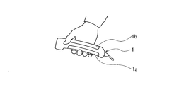
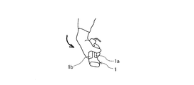
- the hand grips (electrode portions) 1 and 2 are fixed to the user's upper limbs, specifically, while being held by the user's hand, a current is passed through the hand and a voltage is detected to detect the voltage of the user. It is configured to measure bioimpedance.
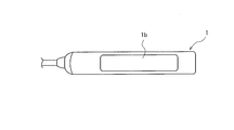
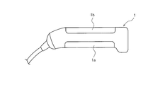
- the handgrip 1 has a current electrode 1a for passing a current through the user's right hand and a voltage electrode 1b for detecting a voltage generated in the right hand when a current is applied from the current electrode 1a to the user's right hand. Be prepared.
- the handgrip 2 has a current electrode 2a for passing a current through the left hand of the user and a voltage electrode 2b for detecting a voltage generated in the left hand when a current is applied from the current electrode 2a to the left hand of the user. Be prepared.
- the hand grips 1 and 2 of the present embodiment are connected to the hand side unit 11 via a cable capable of transmitting measurement data. Details of the hand grips 1 and 2 will be described later with reference to FIGS. 2, 3 and the like.
- the foot side measuring units 3 and 4 are configured to measure the bioimpedance of the user by passing a current through the foot and detecting the voltage.
- the foot-side measuring unit 3 has a current electrode 3a for passing a current through the user's right foot and a voltage electrode 3b for detecting a voltage generated in the right foot when a current is applied from the current electrode 3a to the user's right foot.
- the foot-side measuring unit 4 has a current electrode 4a for passing a current through the user's left foot and a voltage electrode 4b for detecting a voltage generated in the left foot when a current is applied from the current electrode 4a to the user's left foot.
- the foot side unit 12 provided with the foot side measuring units 3 and 4 may be configured to have the function of a weight scale.
- the hand side unit 11 to which the hand grips 1 and 2 are connected and the foot side unit 12 including the foot side measuring units 3 and 4 are connected via the support shaft 13. It is configured so that the bioimpedance of the user's whole body and each part can be measured by using eight electrodes that are integrally arranged so as to be in contact with both hands and feet.
- the biological data measuring device according to the present embodiment does not necessarily have to be applied to an eight-electrode type body composition meter having eight electrodes.
- the biometric data measuring device is a 4-electrode type body that measures a user's bioimpedance using a total of four electrodes provided by the hand grips 1 and 2 without requiring foot-side measuring units 3 and 4. It may be applied to a composition meter.
- the display unit 5 functions as a notification means for notifying the user of the measurement result or the like.
- a liquid crystal display panel such as an LCD (Liquid Crystal Display) is adopted for the display unit 5.
- the operation unit 6 functions as an input interface that accepts user's input operations.
- the operation unit 6 of the present embodiment is composed of a plurality of operation buttons, and the input buttons for inputting basic biological information such as height, gender, and age, and the power of the body composition meter 10 are turned on / off. Includes a power button and the like for turning off.
- the operation unit 6 may be omitted and the function of the operation unit 6 may be included in the display unit 5.
- the hand grip 1 and 2 of this embodiment will be described below.
- the hand grip 1 and the hand grip 2 are symmetrically configured in the body composition meter 10, and have the same basic configuration and functions except that the measurement target is the right hand or the left hand. Therefore, the details of the hand grip 1 for which the user's right hand is to be measured will be described below as a representative.
- FIGS. 2A to 2C and FIGS. 3A to 3B are diagrams for explaining the details of the hand grip 1.
- 2A to 2C are views for explaining the appearance of the hand grip 1.
- 3A to 3B are views for explaining the usage state of the hand grip 1.
- FIG. 3A shows an appropriate usage state of the handgrip 1
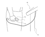
- FIG. 3B shows an example of an inappropriate usage state of the handgrip 1.
- the hand grip 1 is used in a state of being gripped by the user's right hand after being taken out from the holding portion 14. Further, as shown in FIG. 3A, when the user grips the handgrip 1, the fingertip side contacts the current electrode 1a and the palm contacts the voltage electrode 1b, so that the handgrip 1 wobbles at least during the measurement. It is preferable to hold it firmly so that it does not occur. As shown in FIG. 3B, if the grip is too loose, the contact between the user's hand and each electrode becomes insufficient, or the hand grip 1 wobbles during measurement, resulting in significant measurement accuracy. It is not preferable because it will decrease.
- FIG. 3A it is preferable that the hand grip 1 is used in a state where the longitudinal direction is horizontal to the ground by the user's right hand.
- FIG. 2A shows the upper surface of the hand grip 1
- FIG. 2B shows the side surface of the hand grip 1
- FIG. 2C shows the lower surface of the hand grip 1.
- the current electrode 1a is spaced apart from the handgrip 1 as an energizing electrode and the voltage electrode 1b is spaced apart as a measuring electrode. Further, the current electrode 1a is provided on the lower surface of the handgrip 1, and the voltage electrode 1b is provided on the upper surface of the handgrip 1.
- the handgrip 1 When the handgrip 1 is configured in this way, the handgrip 1 is used while applying a current to the fingertip side of the user's right hand in a state of being gripped by the user's right hand as shown in FIG. 3A.
- the voltage can be suitably detected from the palm of the person's right hand.
- the body composition meter 10 measures (calculates) the bioimpedance of the user based on each value of the current applied by at least the pair of hand grips 1 and 2 and the detected voltage, and further measures the measured bioimpedance. Based on the values, values related to body composition such as the user's body fat percentage and visceral fat level can be calculated.
- the measured bioimpedance value is also referred to as a measured value below.
- the bioimpedance of the user measured based on each value of the current applied to the user and the detected voltage using the handgrip 1 varies depending on the state of the user at the time of measurement. For example, when the body water of the user fluctuates (moves) depending on the posture of the user, the bioimpedance also fluctuates according to the amount of fluctuation (movement) of the body water. In addition, the bioimpedance also fluctuates when the user's muscle contracts according to the posture and the cross-sectional area of the muscle changes. In addition, the bioimpedance fluctuates according to changes in the shape of the user's joints, changes in blood flow, and the like.
- the biological data measuring device of the present embodiment was invented in view of such a problem, and it is possible to calculate the value related to the body composition of the user as accurately as possible regardless of the posture of the user at the time of measurement. It is configured so that it can be done.
- the body composition meter 10 is configured to detect the inclination (angle) of the hand grip 1 as a parameter indicating the posture of the user.
- the handgrip 1 of the present embodiment includes a three-axis acceleration sensor 7 as a means for detecting inclination, and detects the angle of each axis (X-axis, Y-axis, Z-axis) as a parameter indicating the posture of the user. Then, the body composition meter 10 corrects the measured value of the bioimpedance measured by the handgrip 1 based on the detected values (X-axis angle, Y-axis angle, Z-axis angle) by the acceleration sensor 7 included in the handgrip 1. To do.
- the body composition meter 10 relates to the body composition calculated based on the measured value of the bioimpedance by correcting the measured value of the bioimpedance according to the posture even if the posture of the user at the time of measurement is disturbed.
- the accuracy of the values can be improved.
- the body composition meter 10 of the present embodiment can more accurately calculate the value related to the body composition of the user regardless of the posture of the user at the time of measurement.
- the details of the functions of the body composition meter 10 of the present embodiment will be described.
- FIG. 4 is a block diagram showing the main functional configurations of the body composition meter 10 in the present embodiment.
- the hand grip 1 and the hand grip 2 have the same basic configuration and functions except for the difference between the right hand and the left hand, the hand grip is represented in FIG. Only 1 is shown. Further, the foot side measuring units 3 and 4 related to the foot side unit 12 are omitted because they are not indispensable configurations as described above.
- the body composition meter 10 has, as its functional configuration, a storage unit 8 and a bioimpedance measurement in addition to the above-mentioned display unit 5, operation unit 6, hand grip 1, current electrode 1a, voltage electrode 1b, and acceleration sensor 7.
- a unit 9 and a control unit 20 including a biometric information calculation unit 27 and a biometric information correction unit 22 are mainly provided.
- the acceleration sensor 7 is provided inside the handgrip 1 as an inclination detecting means, and detects the angle of the handgrip 1 (X-axis angle, Y-axis angle, Z-axis angle). Details of the acceleration sensor 7 will be described with reference to FIGS. 5A to 5C.
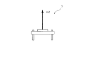
- 5A to 5C are diagrams for explaining the acceleration sensor 7 provided on the hand grip 1.
- 5A to 5B show the axial direction detected by the acceleration sensor 7, and
- FIG. 5C shows an example of arrangement of the acceleration sensor 7 inside the handgrip 1.
- the acceleration sensor 7 of the present embodiment detects a predetermined direction horizontal to the plane direction of the acceleration sensor 7 as the X-axis, and is also horizontal to the plane direction and is the X-axis.
- the direction orthogonal to the Y-axis is detected as the Y-axis.
- the acceleration sensor 7 detects the direction perpendicular to the plane direction as the Z axis.
- the longitudinal direction of the handgrip 1 and the Z-axis direction coincide with each other inside the handgrip 1 in a state where the longitudinal direction is inclined horizontally with respect to the ground, and the hand The grip 1 is arranged so that the lateral direction orthogonal to the longitudinal direction and the Y-axis direction on the upper surface (see FIG. 2B) coincide with each other, and the X-axis direction coincides with the direction perpendicular to the ground.
- the position of the acceleration sensor 7 in the longitudinal direction of the hand grip 1 may be appropriately set in consideration of the detection sensitivity.
- the acceleration sensor 7 By providing the acceleration sensor 7 inside the handgrip 1 in this way, it is possible to detect the angle (X-axis angle, Y-axis angle, Z-axis angle) of the handgrip 1 gripped by the user.
- the acceleration sensor 7 is similarly arranged in the hand grip 2.
- the description will be continued by returning to FIG.
- the bioimpedance measuring unit 9 is composed of a current applying unit 9a electrically connected to the current electrode 1a and a voltage measuring unit 9b electrically connected to the voltage electrode 1b. Then, the current applying unit 9a applies an alternating current to the fingertip side of the user's hand via the current electrode 1a, and the voltage measuring unit 9b detects the voltage of the user's palm via the voltage electrode 1b.
- the biometric information calculation unit 27 functions as a biometric information measuring means for measuring the biometric information of the user using the hand grips 1 and 2.
- the biometric information here includes bioimpedance or body composition. In the present embodiment, the following description will be continued assuming that the biometric information is bioimpedance.
- the bioinformation calculation unit 27 of the present embodiment calculates the bioimpedance of the user based on each value of the current supplied and the detected voltage in the bioimpedance measurement unit 9.
- BIA Bioelectrical impedance analysis
- the biometric information correction unit 22 (hereinafter, also simply referred to as the correction unit 22) is based on the angle (X-axis angle, Y-axis angle, Z-axis angle) of the hand grip 1 detected by the acceleration sensor 7, and the biometric information calculation unit 27 Corrects the measured value of the user's bioimpedance calculated by. Details of the correction will be described later with reference to FIG.
- the storage unit 8 stores a control program that controls the operation of the body composition meter 10. That is, the storage unit 8 functions as a computer-readable storage medium that records a program that realizes the function of the biological data measuring device of the present embodiment.
- the storage unit 8 is composed of a non-volatile memory (ROM; Read Only Memory), a volatile memory (RAM; Random Access Memory), and the like.
- the storage unit 8 corrects the basic bioinformation input to the operation unit 6, the corrected bioimpedance information, and the measured value of the bioimpedance according to the X-axis angle, the Y-axis angle, or the Z-axis angle.
- the map data to be referred to is also stored.
- the control unit 20 is composed of a central processing unit (CPU; Central Processing Unit), an input / output interface connected to each functional configuration as described above, and a bus connecting these to each other.
- the control unit 20 controls each unit of the body composition meter 10 via the input / output interface by reading the control program stored in the storage unit 8 and causing the central processing unit to execute the control program.
- control unit 20 controls each of the hand grips 1 and 2, the display unit 5, the operation unit 6, the bioimpedance measurement unit 9, the storage unit 8, the bioinformation calculation unit 27, and the correction unit 22. At the same time, various arithmetic processes necessary for controlling these are executed. Further, the control unit 20 has detected a body composition calculating means for calculating the user's body composition (body fat percentage in the present embodiment) based on the measured value of the bioimpedance in order to realize each function described later. An abnormal posture determining means for determining whether or not the inclination of the hand grips 1 and 2 is within a predetermined inclination range, and an inclination of the hand grips 1 and 2 assumed when the recommended posture of the user is maintained. It has a function as an abnormal posture degree calculating means for calculating the difference between the detected hand grips 1 and 2 and the inclination of the hand grips 1 and 2.
- a body composition calculating means for calculating the user's body composition (body fat percentage in the present embodiment) based on the measured value of the bioi
- body composition measurement process for measuring the body composition of the user executed by the body composition meter 10
- body composition measurement process for measuring the body composition of the user executed by the body composition meter 10
- an example of calculating the body fat percentage as a kind of body composition of the user is shown.
- the body composition measurement process described below is realized based on the control program stored in the storage unit 8.
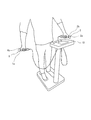
- a user who wants to measure his / her body fat percentage removes the hand grips 1 and 2 from the holding portions 14 and 15, respectively, and holds the hand grip 1 with the right hand and the hand grip 2 with the left hand (see FIG. 3). .. Then, the user maintains the posture as shown in FIG. 7 while the bioimpedance is measured via the hand grips 1 and 2.
- the need to maintain such a posture is notified in advance to the user, for example, by describing it in an instruction manual, or is notified via the display unit 5 immediately before the start of measurement.
- normal posture is a posture recommended for the body composition meter 10 to appropriately measure the bioimpedance of the user, and whether or not a correction described later is necessary for the measured value of the bioimpedance. This is the posture that serves as a reference when determining whether or not.
- the normal posture is a state in which both arms are naturally hung from the shoulders in the direction of gravity as shown in the figure, there is no unnatural spread in the front-back and left-right directions, and the wrists are not bent.
- the body water content of the upper body does not fluctuate abnormally, and the contraction rate of the wrist joints and arm muscles does not change unnaturally.
- the bioimpedance of the body can be measured appropriately.
- the X-axis angle, the Y-axis angle, and the Z-axis angle detected by the acceleration sensor 7 when the user takes such a normal posture are measured values obtained by experiments.
- the reference value may be set uniformly regardless of the body shape, muscle mass, etc. of the user, or may be set according to the body shape, etc. of the user estimated from the basic biological information, etc. input to the operation unit 6. It may be adjusted (increased or decreased).
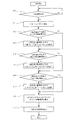
- step S10 the control unit 20 does not move for a certain period of time after the bioimpedance measurement of the user is started by applying the current to the user's hand via the current application unit 9a. Determine if it has been done.
- the constant time is a time required for suitably measuring the bioimpedance, for example, 10 seconds. During this period, the user tries not to move as much as possible in a weakened state.
- step S10 the control unit 20 acquires data (X-axis angle, Y-axis angle, Z-axis angle) related to the inclination of the handgrip 1 from the acceleration sensor 7.
- the process of step S10 functions as an inclination detection step for detecting the inclination of the hand grip 1 as a parameter indicating the posture of the user.
- the control unit 20 detects that the detected values of the voltage electrodes 1b and 2b and / or the detected values of the acceleration sensor 7 fluctuate before a certain period of time elapses, and the user is moving. If it is determined, the process of step S10 is executed again from the beginning. When the control unit 20 executes the process of step S10 again, the user may be notified via the display unit 5 that the posture of the user needs to be corrected to a more appropriate posture.
- the process of step S11 is executed.
- step S11 the biometric information calculation unit 27 is known based on the basic biometric information of the user, the current applied from the current electrodes 1a and 2a and the voltage detected by the voltage electrodes 1b and 2b in step S10.
- the bioimpedance of the user is calculated by.
- the process of step S12 is executed.
- step S12 the control unit 20 determines whether or not the average value of the X-axis angles within a predetermined inclination range in the fixed time required for measuring the bioimpedance in step S10.
- the predetermined inclination range here is set based on the detected value (reference value) of the X-axis angle assumed when the user is in the normal posture. For example, in the present embodiment, ⁇ 5 ° of the reference value is set in a predetermined inclination range of the X-axis angle in consideration of an acceptable measurement error from the viewpoint of ensuring the accuracy of the measurement result of the body fat percentage.
- the reference value is set to 0 °
- FIGS. 8A to 8B are diagrams for explaining an example of a posture (abnormal posture) in which the X-axis angle is determined not to be within a predetermined inclination range in step S12.
- FIG. 8A is a diagram illustrating an example in which the posture of the user is determined to be an abnormal posture due to the degree of bending of the wrist.
- the user in this example bends his / her wrist unnaturally so as to entangle the handgrip 1 inward (body side) while holding the handgrip 1.
- the shape of the joint of the right wrist is different from that in the normal posture, and the contraction rate of the muscles of the arm (especially the forearm) changes as compared with the normal posture. Will fluctuate.
- the X-axis angle detected by the acceleration sensor 7 at the time of measurement is set in the direction perpendicular to the ground.
- the control unit 20 can acquire the difference between the X-axis angle and the reference value (X-axis angle difference ⁇ 1) detected via the acceleration sensor 7 included in the handgrip 1 as a parameter indicating the degree of wrist bending. it can.
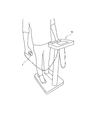
- FIG. 8B is a diagram for explaining an example in which the posture of the user is determined to be an abnormal posture due to the degree of spread of the arms.
- the user in this example unnaturally spreads his arms outward (opposite the body side) while holding the hand grip 1.
- the user's body water fluctuates (moves) from the normal posture, so that the measured bioimpedance fluctuates according to the fluctuation amount (movement amount) of the body water. ..
- the contraction rate of the shoulder muscles and chest muscles also changes as compared with the normal posture, which also causes fluctuations in bioimpedance.
- the X-axis angle detected by the acceleration sensor 7 at the time of measurement is set in the direction perpendicular to the ground.
- the control unit 20 can acquire the difference between the X-axis angle and the reference value (X-axis angle difference ⁇ 2) detected via the acceleration sensor 7 included in the handgrip 1 as a parameter indicating the degree of arm spread. it can.
- the control unit 20 determines whether or not the difference between the average value of the X-axis angles detected in this way and the reference value (for example, the X-axis angle difference ⁇ 1 or ⁇ 2) is within a predetermined range, that is, the X-axis angle. It is determined whether or not the average value is within the predetermined inclination range, and if the average value of the X-axis angles is within the predetermined inclination range, it is determined that the posture of the user is the normal posture, and the step The process of S14 is executed. When it is determined that the average value of the X-axis angles is not within the predetermined inclination range, the posture of the user is determined to be an abnormal posture, and the process of step S13 is executed.
- step S13 the correction unit 22 corrects the measured value of bioimpedance calculated in step S11 based on the difference between the X-axis angle and the reference value detected via the acceleration sensor 7.
- the correction amount is preferably adjusted according to the difference between the detected X-axis angle and the reference value (X-axis angle difference ⁇ 1 or ⁇ 2). For example, the larger the X-axis angle difference ⁇ 2, the smaller the bioimpedance is corrected.
- the correction amount of the bioimpedance with respect to the X-axis angle differences ⁇ 1 and ⁇ 2 is appropriately adjusted so that the corrected bioimpedance becomes an appropriate value.
- the correction amount is determined by, for example, storing map data in which appropriate correction amounts for the X-axis angle differences ⁇ 1 and ⁇ 2 derived by experiments are stored in advance, and the correction unit 22 refers to the map data. Further, the correction amount for the X-axis angle difference ⁇ 1 and ⁇ 2 may be set uniformly regardless of the user's body shape, muscle mass, etc., or may be used estimated from the basic biological information input to the operation unit 6. It may be adjusted (increased or decreased) according to the body shape of the person.
- the correction amount for the X-axis angle difference ⁇ 1 and ⁇ 2 may be adjusted according to the mode of the abnormal posture of the user. For example, in the posture of the user, the degree of extension of the arm has a stronger influence on the fluctuation of the measured bioimpedance than the degree of bending of the wrist. Therefore, for example, even if the absolute values of the X-axis angle differences ⁇ 1 and ⁇ 2 are the same, the X-axis angle difference ⁇ 2 indicating the degree of arm spread is more dependent on the correction amount than the X-axis angle difference ⁇ 1 indicating the degree of wrist bending. It may be weighted so as to have a strong influence.
- the mode of the abnormal posture of the user is based on the assumption that the X-axis angle shows a reference value when the user takes a normal posture, for example, the deviation direction of the X-axis angle detected by the acceleration sensor 7 (for example, positive or negative). ) Can be determined. Further, the handgrip 1 may combine the detection values of not only the acceleration sensor 7 but also other sensors such as a gyro sensor or a distance sensor in order to more accurately grasp the mode of the abnormal posture of the user. It may be configured so that it can be discriminated by using image recognition or the like. On the other hand, the correction amount may be set uniformly according to the absolute values of the X-axis angle differences ⁇ 1 and ⁇ 2 without considering the mode of the abnormal posture. When the measured value of the bioimpedance is corrected based on the X-axis angle differences ⁇ 1 and ⁇ 2, the processing of the subsequent step S14 is executed.
- step S14 the control unit 20 determines whether or not the average value of the Y-axis angles in a certain time required for measuring the bioimpedance in step S10 is within a predetermined inclination range.
- the predetermined inclination range here is set based on the detection value (reference value) of the Y-axis angle assumed when the user is in the normal posture, similarly to the X-axis angle.
- FIG. 9 is a diagram illustrating an example of a posture (abnormal posture) in which it is determined in step S14 that the difference between the average value of the Y-axis angles and the reference value (Y-axis angle difference) is not within a predetermined range.
- FIG. 9 is a diagram for explaining an example in which an abnormal posture is determined due to the angle of the arm in the anteroposterior direction.
- the user in this example excessively raises his arm forward while holding the handgrip 1.
- the body water content of the user, the contraction rate of the muscles around the shoulders, and the like change as compared with the normal posture, so that the measured bioimpedance fluctuates.
- the Y-axis direction detected by the acceleration sensor 7 at the time of measurement is horizontal in the lateral direction of the hand grip 1. It fluctuates upward (lower side when the arm is lowered backward) with respect to the reference value of the Y-axis angle set in the direction. Therefore, the control unit 20 acquires the difference between the Y-axis angle and the reference value detected via the acceleration sensor 7 included in the handgrip 1, that is, the Y-axis angle difference as a parameter indicating how the arm is raised forward. can do.
- the control unit 20 determines whether or not the difference between the average value of the Y-axis angles detected in this way and the reference value is within a predetermined range, that is, the average value of the Y-axis angles is within a predetermined inclination range. If it is determined whether or not the angle is within the predetermined inclination range, it is determined that the user's posture is the normal posture, and the process of step S16 is executed. When it is determined that the average value of the Y-axis angles is not within the predetermined inclination range, the posture of the user is determined to be an abnormal posture, and the process of step S15 is executed.
- step S15 the correction unit 22 corrects the bioimpedance calculated in step S11 based on the difference between the Y-axis angle and the reference value (Y-axis angle difference) detected via the acceleration sensor 7. If necessary, the bioimpedance corrected in step S13 is further corrected.
- the correction amount is preferably adjusted according to the difference between the detected Y-axis angle and the reference value (Y-axis angle difference) in the same manner as described above for the X-axis angle differences ⁇ 1 and ⁇ 2.
- the processing of the following step S16 is executed.
- step S16 the control unit 20 determines whether or not the average value of the Z-axis angles in a certain time required for measuring the bioimpedance in step S10 is within a predetermined inclination range.
- the predetermined inclination range here is set based on the detected value (reference value) of the Z-axis angle assumed when the user is in the normal posture, similarly to the X-axis angle and the Y-axis angle.
- FIG. 10 is a diagram illustrating an example of a posture (abnormal posture) in which the difference between the average value of the Z-axis angles and the reference value (Z-axis angle difference) is determined not to be within a predetermined range in step S16.
- FIG. 10 is a diagram for explaining an example in which the posture of the user is determined to be an abnormal posture due to the degree of twisting of the arm.
- the user in this example excessively twists his arm clockwise (the left hand is counterclockwise) while holding the hand grip 1.
- the contraction rate of the muscles of the user's arm, blood flow, and the like change as compared with the normal posture, so that the measured bioimpedance fluctuates.
- the Z-axis direction detected by the acceleration sensor 7 at the time of measurement is the lateral direction of the hand grip 1. It fluctuates with respect to the reference value in the Z-axis direction set in the horizontal direction. Therefore, the control unit 20 can acquire the difference between the Z-axis angle and the reference value (Z-axis angle difference) detected via the acceleration sensor 7 included in the handgrip 1 as a parameter indicating the degree of arm twist. it can.
- the control unit 20 determines whether or not the difference between the average value of the Z-axis angles detected in this way and the reference value is within a predetermined range, that is, the average value of the Z-axis angles is within a predetermined inclination range. If it is determined whether or not the user's posture is within a predetermined inclination range, it is determined that the user's posture is a normal posture, and the process of step S18 is executed. When it is determined that the average value of the Z-axis angles is not within the predetermined inclination range, the posture of the user is determined to be an abnormal posture, and the process of step S17 is executed.
- step S17 the correction unit 22 corrects the bioimpedance calculated in step S11 based on the difference (Z angle difference) between the Z-axis angle and the reference value detected via the acceleration sensor 7. If necessary, the measured value of bioimpedance corrected in steps S13 and S15 is further corrected.
- the correction amount is preferably adjusted according to the magnitude of the difference between the detected Z-axis angle and the reference value (Z-axis angle difference) in the same manner as described above for the X-axis angle differences ⁇ 1 and ⁇ 2.
- the subsequent process of step S18 is executed.
- step S18 the control unit 20 calculates the body fat percentage of the user by a known method based on the measured value of the bioimpedance corrected by the above flow.
- the processing of the following step S19 is executed.
- step S19 the control unit 20 notifies the user by displaying the measurement result related to the body fat percentage of the user obtained in step S19 on the display unit 5.
- the body composition meter 10 increases the body fat percentage of the user as compared with the conventional one regardless of the posture of the user. It can be calculated accurately.
- the control unit 20 ends the process for measuring the body composition of the user.
- the above is an example of the control executed by the body composition meter 10 of the present embodiment to measure the body composition of the user.
- the processes of steps S10 to S19 related to the above-mentioned flow do not necessarily have to be executed in the above-mentioned order.
- the correction unit 22 does not necessarily have to correct the bioimpedance based on all of the X-axis angle differences ⁇ 1, ⁇ 2, the Y-axis angle difference, and the Z-axis angle difference, and at least one, for example, the X-axis angle difference.
- the correction may be made based only on ⁇ 1 and ⁇ 2.
- the correction unit 22 corrects the bioimpedance based on two or more of the X-axis angle differences ⁇ 1, ⁇ 2, the Y-axis angle difference, and the Z-axis angle difference, the living body of the angle difference of each axis.
- the correction amount may be increased or decreased in consideration of the degree of influence on the impedance.
- the correction unit 22 corrects based only on, for example, the X-axis angle differences ⁇ 1 and ⁇ 2, it is not always necessary to adopt a three-axis acceleration sensor as the acceleration sensor 7, and the one-axis corresponding to the X-axis An acceleration sensor may be adopted.
- the body composition meter 10 may correct the body fat percentage as a value related to the body composition based on at least one of the X-axis angle difference ⁇ 1, ⁇ 2, the Y-axis angle difference, and the Z-axis angle difference.
- the correction unit 22 corrects the body fat percentage as a value related to the body composition based on the angle (X-axis angle, Y-axis angle, Z-axis angle) of the hand grip 1 detected by the acceleration sensor 7. May be good.
- steps S13, S15, and S17 are deleted, and in the process in step S18, the body fat percentage of the user is based on the uncorrected bioimpedance calculated in step S11. Is changed to the process of calculating. Then, between steps S18 and S19, at least one of the X-axis angle differences ⁇ 1, ⁇ 2, the Y-axis angle difference, and the Z-axis angle difference (tilt angle) detected in steps S12, S14, and S16 is set. Based on this, a process for correcting the body fat percentage may be added.
- the biological information calculation unit 27 that functions as the above-mentioned biological information measuring means is a functional unit that includes a body composition calculating means for calculating the user's body composition (body fat percentage in the present embodiment).
- Hand grips 1 and 2 shall be configured to measure the user's body composition.
- the biometric data measuring device (body composition meter 10) includes the energizing electrodes (current electrodes 1a and 1b) and the measuring electrodes (voltage electrodes 1b and 2b) that are spaced apart from each other, and is used by the user. Electrodes (hand grips 1 and 2) that can be fixed to the upper limbs, biometric information measuring means (biological information calculation unit 27) that measures the biometric information of the user using handgrips 1 and 2, and handgrips 1 and 2.
- An inclination detecting means (acceleration sensor 7) for detecting the inclination of the body, and a correction means (biological information correcting unit 22) for correcting the measurement result by the biological information calculation unit 27 according to the inclination of the hand grips 1 and 2 detected by the inclination detecting means. ) And.
- the body composition meter 10 can correct the biological information according to the posture even if the posture of the user at the time of measurement is abnormal, so that the user does not depend on the posture of the user. It is possible to accurately measure the biological information of.
- the measurement result by the biometric information calculation unit 27 includes the bioimpedance of the user or the body composition of the user. Further, when the measurement result is the bioimpedance of the user, the body composition calculation means (control unit 20) for calculating the body composition of the user based on the bioimpedance corrected by the correction means is further provided.
- the measurement result by the biological information calculation unit 27 is the body composition
- the body composition of the user is corrected according to the posture. Therefore, the body composition of the user can be accurately measured regardless of the posture of the user.
- the correction unit 22 may correct the bioimpedance according to the posture even if the posture of the user at the time of measurement is an abnormal posture. it can.
- the body composition meter 10 can improve the accuracy of the values related to the body composition calculated based on the bioimpedance.
- the correction target is the body composition as described above, the correction amount varies depending on the content of the body composition, for example, whether it is the body fat percentage or the muscle mass.
- the measurement result by the biometric information calculation unit 27 is bioimpedance
- the correction target can be narrowed down to one bioimpedance regardless of the content of the body composition. The calculation load is reduced as compared with the case where each of the specific contents is individually corrected accordingly.
- the inclination detecting means is the acceleration sensor 7 provided in the hand grips 1 and 2.
- the body composition meter 10 can detect the angle of the hand grip 1 as a parameter corresponding to the posture of the user at the time of measurement.
- the body composition meter 10 further includes an abnormal posture determining means (control unit 20) for determining whether or not the detected inclinations of the hand grips 1 and 2 are within a predetermined inclination range, and the bioinformation correction unit 22 Corrects the measured value of the bioimpedance when the control unit 20 determines that the inclination of the hand grips 1 and 2 is not within the predetermined inclination range.
- the measured bioimpedance can be more appropriately corrected in consideration of the slight movement (blur) of the user's posture and the measurement error at the time of measurement, which is acceptable from the viewpoint of the accuracy of the measurement result.
- the predetermined inclination range is the hand grips 1 and 2 when the user with the hand grips 1 and 2 fixed maintains the recommended posture when measuring the bioimpedance. Set based on the slope. As a result, an appropriate comparison target for determining the abnormal posture is set, so that the control unit 20 can suitably detect whether or not the posture of the user is abnormal.
- the body composition meter 10 is a hand grip when the user who holds the hand grips 1 and 2 by using the abnormal posture calculation means (control unit 20) maintains the posture recommended when measuring the bioimpedance.
- the difference between the inclinations of 1 and 2 and the detected inclinations of the hand grips 1 and 2 is calculated, and the larger the calculated difference is, the smaller the bioimpedance is corrected.
- the correction amount can be adjusted according to the posture of the user (particularly, the deviation from the recommended posture), so that the measured bioimpedance can be corrected more accurately, and the bioimpedance can be adjusted.
- the accuracy of the values related to the body composition calculated based on the above can be further improved.
- a four-electrode or eight-electrode type body composition meter having at least two hand grips and applying an electric current to both arms or limbs is known.
- a four-electrode type body composition meter that can measure the subcutaneous fat thickness of a user by pressing one electrode portion having a pair of voltage electrodes and a pair of current electrodes against the abdomen or the like is known. Has been done.
- these body composition meters having different measurement points are configured using the same electrodes, they are provided as separate products because the number and arrangement of the required electrodes are different.
- the body composition meter 10 of the present embodiment was invented in view of the above circumstances, and is characterized in that one body composition meter has the functions of two types of body composition meters having different aspects. More specifically, the handgrip 21 included in the body composition meter 10 of the present embodiment applies a current to one arm (right arm in the present embodiment) of the four-electrode or eight-electrode type body composition meter (body fat scale). It is possible to switch between the "normal mode” that functions as a two-electrode body composition meter to be applied and the "sebum thickness meter mode” that functions as a four-electrode type body composition meter that locally measures the user's body composition. The feature is that it is done.
- the details of the body composition meter 10 of the present embodiment will be described with reference to FIGS. 11 to 13. The same functions and configurations as those in the first embodiment will not be described.
- FIGS. 11A to 11D are diagrams for explaining the hand grip 21 of the present embodiment.
- the handgrip 21 of the present embodiment has a function of realizing a "sebum thickness gauge mode" and a function of switching between a "sebum thickness gauge mode” and a "normal mode” with respect to the handgrip 1 described in the first embodiment. It is an added one. However, these functions cannot be added only to the handgrip 1, but can be added only to the handgrip 2 or to both the handgrips 1 and 2. On the premise of the above, the hand grip 21 corresponding to the hand grip 1 will be described below focusing on the differences from the hand grip 1.
- 11A to 11B are diagrams for explaining the configuration of the handgrip 21 in the normal mode.
- 11A to 11B correspond to FIGS. 2A to 2B, respectively.
- the handgrip 21 in the normal mode is configured as a bioimpedance measuring device for the right arm having two electrodes, a current electrode 1a and a voltage electrode 1b, like the handgrip 1 of the first embodiment.
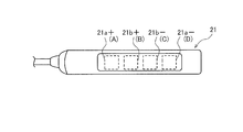
- the hand grip 21 of the present embodiment is composed of at least four adjacent electrodes A to D, and further, these four electrodes A to D are electrically connected to each other.
- a voltage electrode 1b as a measurement electrode is configured.
- FIGS. 11C to 11D are diagrams illustrating the configuration of the hand grip 21 in the sebum thickness gauge mode.
- the portion corresponding to the voltage electrode 1b shown in FIGS. 11A to 11B is divided into four electrodes: a current electrode 21a +, a current electrode 21a-, a voltage electrode 21b +, and a voltage electrode 21b-.
- the four electrodes that function in the sebum thickness gauge mode are electrically connected to each other in the normal mode, so that the four electrodes A to D that constitute one electrode (voltage electrode 1b) are not conductive to each other. It is realized by becoming.
- the portion corresponding to the current electrode 1a shown in FIGS. 11A to 11B loses its function as an electrode by, for example, making it non-conducting to and from the current applying portion 9a.
- the handgrip 21 in the sebum thickness meter mode is a bioimpedance measuring device (subcutaneous fat thickness meter) for local measurement provided with four electrodes of a current electrode 21a +, a current electrode 21a-, a voltage electrode 21b +, and a voltage electrode 21b-. ) Can be realized.
- the method for realizing conduction / non-conduction of the four adjacent electrodes A to D described above is not particularly limited, and for example, from the mode switching unit 26 described later between the adjacent electrodes of the four electrodes A to D. It may be realized by providing a switch circuit (not shown) that turns on and off according to the control signal of. Further, the portion for switching the conduction / non-conduction of the four electrodes A to D does not necessarily have to be between the electrodes A to D provided on the handgrip 21 as shown in the figure, and is controlled with each of the electrodes A to D. It may be any location on the line conducting with the portion 20.
- FIG. 12 is a block diagram showing a main functional configuration of the body composition meter 10 of the present embodiment.
- the foot side measuring units 3 and 4 omitted in the first embodiment and the hand grip 2 in the normal mode are also shown.
- the body composition meter 10 of the present embodiment has a hand grip 2, a foot side measurement unit 3, a foot side measurement unit 4, a display unit 5, an operation unit 6, an acceleration sensor 7, a storage unit 8, and a bioimpedance measurement as its functional configuration.
- the unit (hand side bioimpedance measurement unit) 9 and control unit 20 the hand grip 21, the foot side bioimpedance measurement unit 23, the hand side mode switch 24, the foot side mode switch 25, and the mode It mainly includes a switching unit 26.
- the hand-side bioimpedance measuring unit 9 has a current application unit 9a provided with two output lines (I +, I-) for applying a current, and two input lines (V +, V-) for detecting a voltage. It is composed of a voltage measuring unit 9b provided.
- the connection (electrical connection) between the output line (I +, I-) of the current application unit 9a and the input line (V +, V-) of the voltage measurement unit 9b and each electrode provided in the hand grip 21 and the hand grip 2 is , It is switched according to each measurement mode (normal mode or sebum thickness gauge mode) via the hand side mode switch 24.
- the foot-side bioimpedance measurement unit 23 has a current application unit 23a having two output lines (I +, I-) for applying a current, and two input lines (V +, V-) for detecting a voltage. It is composed of a voltage measuring unit 23b provided. The connection between the output line (I +, I-) of the current application unit 23a and the input line (V +, V-) of the voltage measurement unit 23b and each electrode provided in the foot side measurement unit 3 and the foot side measurement unit 4 is a foot. It is switched according to each measurement mode (normal mode or sebum thickness gauge mode) via the side mode switch 25.
- each measurement mode normal mode or sebum thickness gauge mode
- the mode switching unit 26 switches the measurement mode of the body composition meter 10 based on the angle (at least one of the X-axis angle, the Y-axis angle, and the Z-axis angle) of the handgrip 21 detected by the acceleration sensor 7. More specifically, the mode switching unit 26 controls the hand side mode switching device 24 and the foot side mode switching device 25 according to the angle of the hand grip 21 detected by the acceleration sensor 7, and the body composition meter 10 has a mode switching unit 26. Switch the measurement mode.
- the mode switching unit 26 detects that the user has maintained the hand grip 21 horizontal to the ground for a certain period of time based on the detected angle of the hand grip 21, the body composition meter
- the hand side mode switch 24 and the foot side mode switch 25 are controlled so as to switch the measurement mode of 10 to the "normal mode".
- the mode switching unit 26 detects that the user has maintained the handgrip 21 perpendicular to the ground for a certain period of time based on the detected angle of the handgrip 21, the body composition meter
- the hand side mode switch 24 and the foot side mode switch 25 are controlled so as to switch the measurement mode of 10 to the “sebum thickness gauge mode”.
- the angle of the hand grip 21 and the time for maintaining the angle may be appropriately set as to which measurement mode the trigger corresponds to.
- the hand-side mode switch 24 switches the connection between the input / output line of the hand-side bioimpedance measurement unit 9 and each electrode provided in the hand grips 2 and 22 according to the control signal (mode switching signal) from the mode switching unit 26. ..
- the hand-side mode switcher 24 sets the output line I + of the current application unit 9a to the current electrode 21a + and the output line I ⁇ .
- the input line V + of the voltage measuring unit 9b is connected to the voltage electrode 21b +, and the input line V- is connected to the voltage electrode 21b-.
- the connection of the hand-side mode switch 24 shown in FIG. 12 is the connection in the "sebum thickness gauge mode".
- the hand-side mode switch 24 connects the output line I + of the current application unit 9a to the current electrode 1a and the output line I- to the current electrode 2a, respectively.
- the input line V + of the voltage measuring unit 9b is connected to the voltage electrode 1b, and the input line V- is connected to the voltage electrode 2b.
- the foot side mode switch 25 connects the input / output line of the foot side bioimpedance measurement unit 23 and each electrode provided in the foot side measurement units 3 and 4 according to the control signal (mode switching signal) from the mode switching unit 26. To switch.
- the foot side mode switch 25 is the input / output line of the foot side bioimpedance measurement unit 23 and the foot side measurement units 3 and 4. Disconnect each electrode provided by.
- the measurement mode of the body composition meter 10 can be set to the sebum thickness meter mode.
- the state of the foot side mode switch 25 shown in FIG. 12 is the state at the time of "sebum thickness gauge mode".
- the foot side mode switch 25 connects the output line I + of the current application unit 23a to the current electrode 3a and the output line I- to the current electrode 4a, respectively.
- the input line V + of the voltage measuring unit 23b is connected to the voltage electrode 3b, and the input line V- is connected to the voltage electrode 4b.
- the control unit 20 is the same as the above-mentioned "sebum thickness meter mode".
- the input / output lines of the side bioimpedance measurement unit 23 and the electrodes provided by the foot side measurement units 3 and 4 may be disconnected to eliminate the functions of the foot side measurement units 3 and 4.
- the foot-side bioimpedance measuring unit 23, the foot-side mode switch 25, and the foot-side measuring units 3 and 4 may be deleted from the configuration of the body composition meter 10.
- the details of the process (mode switching process) for switching the measurement mode of the body composition meter 10 executed by the body composition meter 10 of the present embodiment will be described.
- the body fat scale mode for measuring the body fat percentage of the user is set as the "normal mode”
- the mode for locally measuring the sebum thickness of the user using the handgrip 21 is set as the "sebum thickness measuring mode”.
- An example of switching the measurement mode between the "normal mode” and the "sebum thickness gauge mode” is shown.
- the mode switching process described below is realized based on the control program stored in the storage unit 8.
- the mode switching process described below starts on the premise that the user has at least the handgrip 21.
- step S20 the mode switching unit 26 acquires the angle of the handgrip 21 (at least one of the X-axis angle, the Y-axis angle, and the Z-axis angle) detected by the acceleration sensor 7 included in the handgrip 21.
- the user tilts the handgrip 21 to an angle corresponding to each mode in order to set the desired measurement mode.
- the angle condition ⁇ the angle condition corresponding to the "normal mode”
- the angle condition ⁇ the user wants to select the normal mode. Tilts the handgrip 21 for a certain period of time so as to satisfy the angle condition ⁇ .
- the angle conditions ⁇ and ⁇ may be set as appropriate.
- the angle condition ⁇ the angle when the longitudinal direction of the handgrip 21 is tilted horizontally with respect to the ground is set as the angle condition ⁇
- the angle condition ⁇ the angle when the longitudinal direction of the handgrip 21 is tilted perpendicular to the ground is set as the angle condition ⁇ .
- a certain angle may be set to one angle condition (for example, the angle condition ⁇ ), and an angle other than the angle condition ⁇ may be set to the angle condition ⁇ .
- step S21 the mode switching unit 26 determines whether or not the angle condition ⁇ is maintained for a certain period of time.
- the fixed time here may be appropriately set from the viewpoint of appropriately reading the angle of the handgrip 21 intended by the user, and is, for example, 3 seconds.
- the process of step S22 is executed. If it is determined that the angle condition ⁇ is not maintained for a certain period of time, the process of step S24 is executed.
- the mode switching unit 26 controls the hand side mode switching device 24 and the foot side mode switching device 25, and arranges (connects) the electrodes of the hand grips 2, 21 and the foot side measuring units 3 and 4. Is set to the normal mode (see FIGS. 11A-11B and 12).
- the control unit 20 may notify the user via the display unit 5 that the measurement mode of the body composition meter 10 is set to the “normal mode”.
- step S23 the control unit 20 starts measuring the bioimpedance of the user as an eight-electrode or four-electrode type body fat scale, and ends the mode switching process.
- the body composition measurement process described above in the first embodiment or the correction according to the detection value (tilt angle) of the acceleration sensor 7 as described in the first embodiment is performed.
- a known body composition measurement process that is not performed is performed.
- step S24 the mode switching unit 26 determines whether or not the angle condition ⁇ is maintained for a certain period of time.
- the process of step S25 is executed. If it is determined that the angle condition ⁇ is not maintained for a certain period of time, the process of step S20 is executed in order to acquire the angle of the handgrip 21 again.
- step S24 may be deleted when the angle condition ⁇ is an angle other than the angle corresponding to the angle condition ⁇ as described above. In this case, if step S21 is denied (NO determination), step S25 is subsequently executed.
- step S25 the mode switching unit 26 controls the hand side mode switching device 24 and the foot side mode switching device 25, and arranges (connects) the electrodes of the hand grips 2, 21 and the foot side measuring units 3 and 4. Is set to the sebum thickness gauge mode (see FIGS. 11C to 11D and FIG. 12).
- the control unit 20 may notify the user via the display unit 5 that the measurement mode of the body composition meter 10 is set to the “sebum thickness meter mode”.
- step S26 the control unit 20 starts the bioimpedance measurement as a sebum thickness gauge using the hand grip 21 provided with four electrodes, and ends the mode switching process.
- the control unit 20 measures the user's local sebum thickness by a known method. According to the flow described above, the user can easily switch between the two functions of the body composition meter 10 by a simple act of changing the inclination of the handgrip 21.
- the handgrip 21 has a first measurement mode (normal mode) in which a set of energizing electrodes (current electrode 1a) and measuring electrodes (voltage electrode 1b) function. It is configured to be switchable between two sets of local energization electrodes (current electrodes 21a +, 21a-) and a second measurement mode (skin oil thickness gauge mode) in which local measurement electrodes (voltage electrodes 21b +, 21b-) function.
- the body composition meter 10 further includes a mode switching means (mode switching unit 26) for switching between the first measurement mode and the second measurement mode according to the tilt of the hand grip 21 detected by the tilt detecting means (acceleration sensor 7). ..
- the user can use each function with one device without separately obtaining two devices having each function, which is advantageous in terms of cost and space for mounting the device.
- the local sebum thickness can be measured by a series of subsequent actions, so that the user can measure himself / herself with a simple operation. It is an advantage that the body composition of the body can be measured from various angles. Further, according to such an advantage, the body composition meter 10 of the present embodiment can improve the motivation of the user to measure his / her own body composition in more detail.
- either one of the current electrode 1a and the voltage electrode 1b is composed of at least four adjacent electrodes A to D, and the mode switching means (mode switching unit).
- mode switching unit mode switching unit
- a set of energizing electrodes (current electrode 1a) and measuring electrodes are connected to the handgrip 21 by conducting at least four electrodes A to D with each other.
- (voltage electrode 1b) is configured and the handgrip 21 is set to the second measurement mode, at least four electrodes A to D are made non-conducting to each other so as to be electrically divided into four, and the current-carrying electrodes.
- Electrodes 21a +, 21a- are configured.
- Electrodes 21b +, 21b- are configured.
- at least a part of the electrode used for the function corresponding to the first measurement mode and the electrode used for the function corresponding to the second measurement mode can be shared, so that the above two functions are provided.
- the total number of electrodes and the placement space required to realize the body composition meter 10 can be suppressed.
- the electrode portion does not necessarily have to be the hand grip as described above with reference to FIG. 2 and the like.
- the electrode portion may have a function similar to that of the hand grips 1 and 2 described above in measuring the bioimpedance of the user, and may have a shape that can be fixed to the upper limb of the user.
- the electrode portion has, for example, a clip-shaped sandwiching portion, and is configured to be able to be fixed to the user by sandwiching the upper limb (forearm portion) of the user with the sandwiching portion. You may.
- the tilt detecting means is not limited to the acceleration sensor 7.
- the tilt detecting means may use another sensor such as a gyro sensor as long as the tilt of the hand grip 1 can be detected as a parameter indicating the posture of the user during the bioimpedance measurement.
- the tilt detecting means is not limited to the sensor, and the tilt of the hand grip may be detected by using a known mechanism, image recognition, or the like.
- the shape of the body composition meter 10 is not limited to the shape described with reference to the drawings and the like, and may be appropriately changed as long as it has the above-mentioned functions.
- the shapes of the hand grips 1, 2, and 21 are not limited to those shown in the figure, and may be appropriately changed in consideration of ease of grip, stability of the posture of the user at the time of measurement, and the like.
- the configuration of the body composition meter 10 is not limited to the configuration described with reference to the drawings and the like, and may be appropriately changed as long as it has the above-mentioned functions.
- the arrangement of the electrodes included in the hand grips 1, 2 and 21 can be appropriately replaced as long as each of the above-mentioned functions operates appropriately corresponding to each measurement mode.
- the electrodes A to D described with reference to FIGS. 11A to 11D do not necessarily have to be four electrodes adjacent to each other in a row.
- the current electrode 1a or the voltage electrode 1b of the handgrip 21 may be composed of five or more electrodes as long as it can be divided into four adjacent electrodes.
- the current electrode 1a or the voltage electrode 1b when the current electrode 1a or the voltage electrode 1b is composed of five electrodes, two adjacent electrodes are made conductive, and the two electrodes and the other three electrodes are made non-conducting to each other.
- the current electrode 1a or the voltage electrode 1b may be configured so as to be divided into four electrodes that are non-conducting to each other.
- the directions (X-axis direction, Y-axis direction, Z-axis direction) detected by the acceleration sensors 7 provided on the hand grips 1, 2 and 21 described above are examples and can be changed as appropriate.
- the abnormal posture of the user detected corresponding to each axial direction described with reference to FIGS. 8 to 10 is an example, and is not limited to the illustrated one.
- the axial direction detected by the acceleration sensor 7 in response to the inclination of the hand grips 1, 2 and 21 and the abnormal posture detected in response to the fluctuation in the axial direction may be appropriately adjusted or changed.
- FIGS. 6 and 13 do not necessarily have all the steps shown in the drawings, and do not necessarily have to be executed in the order shown in the drawings.
- other steps may be included as long as the above-mentioned functions are not impaired.
- a step of determining that a normal posture (reference value) is detected may be added as a measurement start condition of the body composition measurement process shown in FIG. 6, a step of determining that a normal posture (reference value) is detected may be added. By adding such a step, the body composition measurement process shown in FIG. 6 can set the measurement start condition that the user holding the hand grips 1 and 2 takes a normal posture at least once. it can.
- the mode switching process described above in the second embodiment is not limited to the mode described in FIG.
- the sebum thickness gauge mode is switched to.
- the mode may be switched again to the normal mode, and the measurement of the body fat percentage may be started again.
- the mode switching process may be configured to switch according to the operation of the user acquired via the operation unit 6.
- the mode switching process is determined by the user, such as automatically switching to the sebum thickness gauge mode after the measurement in the normal mode is completed, or automatically switching to the normal mode after the measurement in the sebum thickness gauge mode is completed.
- the operation mode may be switched as a series of flow of the measurement process executed in each operation mode without requiring the switching operation of.
- the terms used in the description of the hand grips 1, 2 and 21 and the description of the axial direction detected by the acceleration sensor 7 in the horizontal direction, the vertical direction and the like are not necessarily strictly defined. It is not intended to indicate the exact direction.
- the direction specified in the present specification may include some deviation within an acceptable range from the viewpoint of the measurement accuracy of the body composition measured by the body composition meter 10.
- Body composition meter biological data measuring device
- Control unit body composition calculation means, abnormal posture determination means, abnormal posture degree calculation means) 21a +, 21a-Current electrode (electrode for local energization) 21b +, 21b- Voltage electrodes (electrodes for local measurement) 22 Biometric information correction unit (correction means) 26 Mode switching unit (mode switching means) 27 Biometric information calculation unit (biological information measuring means) S10 (tilt detection step) S13, S15, S17 (correction step) S18 (body composition calculation step) S19 (Notification step)
Landscapes
- Health & Medical Sciences (AREA)
- Life Sciences & Earth Sciences (AREA)
- Surgery (AREA)
- Animal Behavior & Ethology (AREA)
- Pathology (AREA)
- Engineering & Computer Science (AREA)
- Biomedical Technology (AREA)
- Heart & Thoracic Surgery (AREA)
- Medical Informatics (AREA)
- Molecular Biology (AREA)
- Physics & Mathematics (AREA)
- Biophysics (AREA)
- General Health & Medical Sciences (AREA)
- Public Health (AREA)
- Veterinary Medicine (AREA)
- Nuclear Medicine, Radiotherapy & Molecular Imaging (AREA)
- Radiology & Medical Imaging (AREA)
- Physiology (AREA)
- Dentistry (AREA)
- Oral & Maxillofacial Surgery (AREA)
- Measurement And Recording Of Electrical Phenomena And Electrical Characteristics Of The Living Body (AREA)
- Measurement Of The Respiration, Hearing Ability, Form, And Blood Characteristics Of Living Organisms (AREA)
Priority Applications (3)
| Application Number | Priority Date | Filing Date | Title |
|---|---|---|---|
| US17/599,414 US20220211290A1 (en) | 2019-03-29 | 2020-03-27 | Biological data measurement apparatus, biological data measurement method, and non-transitory computer-readable recording medium |
| EP20783519.0A EP3949852A4 (en) | 2019-03-29 | 2020-03-27 | DEVICE FOR MEASURING BIOLOGICAL DATA, METHOD FOR MEASURING BIOLOGICAL DATA AND PROGRAM |
| CN202080025502.3A CN113631091A (zh) | 2019-03-29 | 2020-03-27 | 生物数据测量装置、生物数据测量方法和程序 |
Applications Claiming Priority (2)
| Application Number | Priority Date | Filing Date | Title |
|---|---|---|---|
| JP2019-068650 | 2019-03-29 | ||
| JP2019068650A JP7233692B2 (ja) | 2019-03-29 | 2019-03-29 | 生体データ測定装置、生体データ測定方法及びプログラム |
Publications (1)
| Publication Number | Publication Date |
|---|---|
| WO2020203893A1 true WO2020203893A1 (ja) | 2020-10-08 |
Family
ID=72668191
Family Applications (1)
| Application Number | Title | Priority Date | Filing Date |
|---|---|---|---|
| PCT/JP2020/014328 Ceased WO2020203893A1 (ja) | 2019-03-29 | 2020-03-27 | 生体データ測定装置、生体データ測定方法及びプログラム |
Country Status (5)
| Country | Link |
|---|---|
| US (1) | US20220211290A1 (enExample) |
| EP (1) | EP3949852A4 (enExample) |
| JP (2) | JP7233692B2 (enExample) |
| CN (1) | CN113631091A (enExample) |
| WO (1) | WO2020203893A1 (enExample) |
Cited By (1)
| Publication number | Priority date | Publication date | Assignee | Title |
|---|---|---|---|---|
| WO2022230593A1 (ja) * | 2021-04-26 | 2022-11-03 | 株式会社タニタ | 体組成計、体組成測定方法、体組成測定プログラム、及びコンピュータ読み取り可能な非一時的記憶媒体 |
Families Citing this family (6)
| Publication number | Priority date | Publication date | Assignee | Title |
|---|---|---|---|---|
| WO2021106162A1 (ja) * | 2019-11-28 | 2021-06-03 | 日本電信電話株式会社 | 監視システム、監視方法、および監視プログラム |
| CN113456050B (zh) * | 2021-07-23 | 2023-12-19 | 芯海科技(深圳)股份有限公司 | 人体阻抗测量装置及人体阻抗测量方法 |
| CN114631687B (zh) * | 2022-03-07 | 2023-05-12 | 深圳市瑞必达科技有限公司 | 升降桌不计算欧拉角做敲击保护和倾斜保护的控制方法 |
| CN116138763A (zh) * | 2023-03-31 | 2023-05-23 | 芯海科技(深圳)股份有限公司 | 一种人体阻抗测量方法及可穿戴设备 |
| CN121099948A (zh) * | 2023-05-11 | 2025-12-09 | 费森尤斯医疗保健控股公司 | 使用生物阻抗确定流体状态 |
| JP2025139894A (ja) * | 2024-03-13 | 2025-09-29 | オムロンヘルスケア株式会社 | 生体情報測定装置、生体情報測定方法及びプログラム |
Citations (7)
| Publication number | Priority date | Publication date | Assignee | Title |
|---|---|---|---|---|
| JPH11113871A (ja) * | 1997-10-20 | 1999-04-27 | Omron Corp | 健康管理指針アドバイス装置 |
| JP2001149328A (ja) * | 1999-11-30 | 2001-06-05 | Omron Corp | 健康管理指針アドバイス装置 |
| JP2003159227A (ja) * | 2001-11-27 | 2003-06-03 | Omron Corp | 健康管理指針アドバイス装置 |
| JP2007296266A (ja) * | 2006-05-08 | 2007-11-15 | Physio Trace Kk | 生体センサ装置 |
| JP2009050412A (ja) * | 2007-08-25 | 2009-03-12 | Tanita Corp | 生体データ測定器 |
| US20130023740A1 (en) * | 2011-07-21 | 2013-01-24 | Jens Kirchner | Device and method for monitoring physiological signals |
| JP2019068650A (ja) | 2017-10-02 | 2019-04-25 | 株式会社豊田自動織機 | 電動圧縮機用インバータモジュール |
Family Cites Families (12)
| Publication number | Priority date | Publication date | Assignee | Title |
|---|---|---|---|---|
| JPH09285455A (ja) * | 1996-02-23 | 1997-11-04 | Omron Corp | 健康管理指針アドバイス装置 |
| JP2005230120A (ja) * | 2004-02-17 | 2005-09-02 | Tanita Corp | インピーダンス測定装置及び体組成測定装置 |
| KR100893958B1 (ko) * | 2007-05-10 | 2009-04-20 | 주식회사 지앤알 | 정확한 측정자세 유도기능이 있는 체성분 분석 장치 및 그방법 |
| JP5163197B2 (ja) * | 2008-03-14 | 2013-03-13 | オムロンヘルスケア株式会社 | 姿勢評価装置 |
| DE102014205838A1 (de) | 2013-08-07 | 2015-02-12 | Robert Bosch Gmbh | Verfahren und Vorrichtung zur Personenidentifikation |
| KR20150081735A (ko) * | 2014-01-06 | 2015-07-15 | 삼성전자주식회사 | 모바일 디바이스의 체지방 측정 방법 및 장치 |
| KR102299364B1 (ko) * | 2014-08-25 | 2021-09-07 | 삼성전자주식회사 | 웨어러블 디바이스의 센서가 측정하는 임피던스 값을 보정하는 방법 및 장치 |
| KR20160086715A (ko) * | 2015-01-12 | 2016-07-20 | 삼성전자주식회사 | 웨어러블 생체 정보 측정 장치 및 이를 이용한 생체 정보 측정 방법 |
| KR102440484B1 (ko) * | 2015-02-16 | 2022-09-07 | 삼성전자주식회사 | 생체 정보를 측정하는 전자 장치 및 방법 |
| KR102556007B1 (ko) * | 2015-10-07 | 2023-07-17 | 삼성전자주식회사 | 생체신호 측정장치 및 방법 |
| CN205964016U (zh) * | 2016-04-13 | 2017-02-22 | 欧姆龙健康医疗事业株式会社 | 人体成分测量装置 |
| KR101980379B1 (ko) * | 2017-06-15 | 2019-05-20 | (주)대우루컴즈 | 휴대용 체성분 분석장치 및 그 방법 |
-
2019
- 2019-03-29 JP JP2019068650A patent/JP7233692B2/ja active Active
-
2020
- 2020-03-27 US US17/599,414 patent/US20220211290A1/en not_active Abandoned
- 2020-03-27 EP EP20783519.0A patent/EP3949852A4/en not_active Withdrawn
- 2020-03-27 WO PCT/JP2020/014328 patent/WO2020203893A1/ja not_active Ceased
- 2020-03-27 CN CN202080025502.3A patent/CN113631091A/zh active Pending
-
2023
- 2023-02-15 JP JP2023021793A patent/JP7540774B2/ja active Active
Patent Citations (8)
| Publication number | Priority date | Publication date | Assignee | Title |
|---|---|---|---|---|
| JPH11113871A (ja) * | 1997-10-20 | 1999-04-27 | Omron Corp | 健康管理指針アドバイス装置 |
| JP2001149328A (ja) * | 1999-11-30 | 2001-06-05 | Omron Corp | 健康管理指針アドバイス装置 |
| JP2003159227A (ja) * | 2001-11-27 | 2003-06-03 | Omron Corp | 健康管理指針アドバイス装置 |
| JP2007296266A (ja) * | 2006-05-08 | 2007-11-15 | Physio Trace Kk | 生体センサ装置 |
| JP2009050412A (ja) * | 2007-08-25 | 2009-03-12 | Tanita Corp | 生体データ測定器 |
| JP5493198B2 (ja) | 2007-08-25 | 2014-05-14 | 株式会社タニタ | 生体データ測定器 |
| US20130023740A1 (en) * | 2011-07-21 | 2013-01-24 | Jens Kirchner | Device and method for monitoring physiological signals |
| JP2019068650A (ja) | 2017-10-02 | 2019-04-25 | 株式会社豊田自動織機 | 電動圧縮機用インバータモジュール |
Cited By (2)
| Publication number | Priority date | Publication date | Assignee | Title |
|---|---|---|---|---|
| WO2022230593A1 (ja) * | 2021-04-26 | 2022-11-03 | 株式会社タニタ | 体組成計、体組成測定方法、体組成測定プログラム、及びコンピュータ読み取り可能な非一時的記憶媒体 |
| JP2022168714A (ja) * | 2021-04-26 | 2022-11-08 | 株式会社タニタ | 体組成計、体組成測定方法、及び体組成測定プログラム |
Also Published As
| Publication number | Publication date |
|---|---|
| JP7233692B2 (ja) | 2023-03-07 |
| JP2023056003A (ja) | 2023-04-18 |
| JP2020163015A (ja) | 2020-10-08 |
| US20220211290A1 (en) | 2022-07-07 |
| EP3949852A1 (en) | 2022-02-09 |
| CN113631091A (zh) | 2021-11-09 |
| JP7540774B2 (ja) | 2024-08-27 |
| EP3949852A4 (en) | 2022-11-23 |
Similar Documents
| Publication | Publication Date | Title |
|---|---|---|
| JP7233692B2 (ja) | 生体データ測定装置、生体データ測定方法及びプログラム | |
| US6643543B2 (en) | Body water amount condition judging apparatus by multi-frequency bioelectric impedance measurement | |
| JP4609463B2 (ja) | 生体インピーダンス測定用ハンドユニット | |
| WO1999060925A1 (en) | Body fat meter with stature measuring instrument | |
| JP2009056010A (ja) | 体組成体重計 | |
| JP2015134074A (ja) | 生体測定装置 | |
| JP4369855B2 (ja) | 柔軟運動用器具 | |
| EP1092388B1 (en) | Body composition measuring apparatus with built-in weight meter | |
| JP4586727B2 (ja) | 体組成計 | |
| JP2001078978A (ja) | 健康管理指針アドバイス装置 | |
| WO2019188687A1 (ja) | 体水分量の測定装置、測定方法、および測定プログラム | |
| CN116194997A (zh) | 健康水平判定系统、健康水平判定程序和健康水平判定服务器 | |
| KR100423678B1 (ko) | 핸드그립을 갖춘 생체전기 임피던스 측정장치 | |
| JP3772617B2 (ja) | 健康管理指針アドバイス装置 | |
| WO2012111210A1 (ja) | 胴部幅測定装置および体脂肪測定装置 | |
| JP4423768B2 (ja) | 体脂肪測定装置 | |
| JP2011191088A (ja) | 荷重計 | |
| JP2000023934A (ja) | 体脂肪測定装置 | |
| JP4484150B2 (ja) | 体組成計 | |
| JP2002186592A (ja) | 生体インピーダンス測定装置 | |
| JP2004129779A (ja) | 生体情報測定装置 | |
| JP4196035B2 (ja) | 体脂肪測定装置 | |
| JP5494311B2 (ja) | 腹部脂肪量測定装置 |
Legal Events
| Date | Code | Title | Description |
|---|---|---|---|
| 121 | Ep: the epo has been informed by wipo that ep was designated in this application |
Ref document number: 20783519 Country of ref document: EP Kind code of ref document: A1 |
|
| NENP | Non-entry into the national phase |
Ref country code: DE |
|
| ENP | Entry into the national phase |
Ref document number: 2020783519 Country of ref document: EP Effective date: 20211029 |