WO2020203472A1 - Photocurable resin composition for imprinting, production method for photocurable resin composition for imprinting, and production method for pattern-formed body - Google Patents
Photocurable resin composition for imprinting, production method for photocurable resin composition for imprinting, and production method for pattern-formed body Download PDFInfo
- Publication number
- WO2020203472A1 WO2020203472A1 PCT/JP2020/013059 JP2020013059W WO2020203472A1 WO 2020203472 A1 WO2020203472 A1 WO 2020203472A1 JP 2020013059 W JP2020013059 W JP 2020013059W WO 2020203472 A1 WO2020203472 A1 WO 2020203472A1
- Authority
- WO
- WIPO (PCT)
- Prior art keywords
- photocurable resin
- imprint
- resin composition
- polymerizable compound
- group
- Prior art date
Links
- 239000011342 resin composition Substances 0.000 title claims abstract description 180
- 238000004519 manufacturing process Methods 0.000 title claims description 84
- 150000001875 compounds Chemical class 0.000 claims abstract description 135
- XUIMIQQOPSSXEZ-UHFFFAOYSA-N Silicon Chemical group [Si] XUIMIQQOPSSXEZ-UHFFFAOYSA-N 0.000 claims abstract description 113
- 125000004430 oxygen atom Chemical group O* 0.000 claims abstract description 111
- 229910052710 silicon Inorganic materials 0.000 claims abstract description 98
- 125000000524 functional group Chemical group 0.000 claims abstract description 81
- 239000003999 initiator Substances 0.000 claims abstract description 27
- 239000000463 material Substances 0.000 claims description 87
- 229910000077 silane Inorganic materials 0.000 claims description 82
- BLRPTPMANUNPDV-UHFFFAOYSA-N Silane Chemical compound [SiH4] BLRPTPMANUNPDV-UHFFFAOYSA-N 0.000 claims description 81
- 229920005989 resin Polymers 0.000 claims description 69
- 239000011347 resin Substances 0.000 claims description 69
- 238000000034 method Methods 0.000 claims description 58
- 230000001588 bifunctional effect Effects 0.000 claims description 36
- 239000000203 mixture Substances 0.000 claims description 30
- KPUWHANPEXNPJT-UHFFFAOYSA-N disiloxane Chemical class [SiH3]O[SiH3] KPUWHANPEXNPJT-UHFFFAOYSA-N 0.000 claims description 29
- 230000015572 biosynthetic process Effects 0.000 claims description 28
- 238000003786 synthesis reaction Methods 0.000 claims description 25
- 239000004094 surface-active agent Substances 0.000 claims description 20
- 238000000576 coating method Methods 0.000 claims description 19
- 238000001723 curing Methods 0.000 claims description 19
- 239000000470 constituent Substances 0.000 claims description 17
- 239000011248 coating agent Substances 0.000 claims description 15
- 238000005530 etching Methods 0.000 claims description 14
- 239000003223 protective agent Substances 0.000 claims description 13
- 150000004756 silanes Chemical class 0.000 claims description 13
- YCKRFDGAMUMZLT-UHFFFAOYSA-N Fluorine atom Chemical compound [F] YCKRFDGAMUMZLT-UHFFFAOYSA-N 0.000 claims description 12
- 229910052731 fluorine Inorganic materials 0.000 claims description 12
- 239000011737 fluorine Substances 0.000 claims description 12
- 125000004435 hydrogen atom Chemical group [H]* 0.000 claims description 11
- 229920001296 polysiloxane Polymers 0.000 claims description 10
- 125000002887 hydroxy group Chemical group [H]O* 0.000 claims description 8
- 125000006239 protecting group Chemical group 0.000 claims description 7
- 238000006482 condensation reaction Methods 0.000 claims description 6
- 230000001678 irradiating effect Effects 0.000 claims description 6
- 125000003647 acryloyl group Chemical group O=C([*])C([H])=C([H])[H] 0.000 claims description 5
- 125000000962 organic group Chemical group 0.000 claims description 5
- 125000003700 epoxy group Chemical group 0.000 claims description 4
- 125000003566 oxetanyl group Chemical group 0.000 claims description 4
- 230000002378 acidificating effect Effects 0.000 claims description 3
- 238000000016 photochemical curing Methods 0.000 claims description 3
- 239000007787 solid Substances 0.000 claims description 3
- 230000000087 stabilizing effect Effects 0.000 claims description 2
- 230000003373 anti-fouling effect Effects 0.000 description 30
- 125000000217 alkyl group Chemical group 0.000 description 29
- -1 polysiloxane structure Polymers 0.000 description 26
- 239000000758 substrate Substances 0.000 description 24
- 238000011156 evaluation Methods 0.000 description 22
- 125000004432 carbon atom Chemical group C* 0.000 description 21
- 238000000465 moulding Methods 0.000 description 16
- 238000006243 chemical reaction Methods 0.000 description 15
- 238000012546 transfer Methods 0.000 description 15
- 230000008859 change Effects 0.000 description 14
- IJOOHPMOJXWVHK-UHFFFAOYSA-N chlorotrimethylsilane Chemical compound C[Si](C)(C)Cl IJOOHPMOJXWVHK-UHFFFAOYSA-N 0.000 description 14
- VYPSYNLAJGMNEJ-UHFFFAOYSA-N silicon dioxide Inorganic materials O=[Si]=O VYPSYNLAJGMNEJ-UHFFFAOYSA-N 0.000 description 14
- 235000012239 silicon dioxide Nutrition 0.000 description 13
- 238000003860 storage Methods 0.000 description 13
- KFZMGEQAYNKOFK-UHFFFAOYSA-N Isopropanol Chemical compound CC(C)O KFZMGEQAYNKOFK-UHFFFAOYSA-N 0.000 description 12
- 239000007789 gas Substances 0.000 description 12
- 239000010453 quartz Substances 0.000 description 12
- 238000002834 transmittance Methods 0.000 description 12
- 238000006116 polymerization reaction Methods 0.000 description 11
- 239000002994 raw material Substances 0.000 description 11
- 230000009257 reactivity Effects 0.000 description 11
- XLYOFNOQVPJJNP-UHFFFAOYSA-N water Substances O XLYOFNOQVPJJNP-UHFFFAOYSA-N 0.000 description 11
- 230000000052 comparative effect Effects 0.000 description 10
- 239000000243 solution Substances 0.000 description 10
- 239000010703 silicon Substances 0.000 description 9
- 230000002123 temporal effect Effects 0.000 description 9
- LWRBVKNFOYUCNP-UHFFFAOYSA-N 2-methyl-1-(4-methylsulfanylphenyl)-2-morpholin-4-ylpropan-1-one Chemical compound C1=CC(SC)=CC=C1C(=O)C(C)(C)N1CCOCC1 LWRBVKNFOYUCNP-UHFFFAOYSA-N 0.000 description 8
- KBQVDAIIQCXKPI-UHFFFAOYSA-N 3-trimethoxysilylpropyl prop-2-enoate Chemical compound CO[Si](OC)(OC)CCCOC(=O)C=C KBQVDAIIQCXKPI-UHFFFAOYSA-N 0.000 description 8
- WYURNTSHIVDZCO-UHFFFAOYSA-N Tetrahydrofuran Chemical compound C1CCOC1 WYURNTSHIVDZCO-UHFFFAOYSA-N 0.000 description 8
- 239000003054 catalyst Substances 0.000 description 8
- 238000010586 diagram Methods 0.000 description 8
- 125000003545 alkoxy group Chemical group 0.000 description 7
- 230000000694 effects Effects 0.000 description 7
- 239000010410 layer Substances 0.000 description 7
- 230000003287 optical effect Effects 0.000 description 7
- 125000001997 phenyl group Chemical group [H]C1=C([H])C([H])=C(*)C([H])=C1[H] 0.000 description 7
- VEXZGXHMUGYJMC-UHFFFAOYSA-N Hydrochloric acid Chemical compound Cl VEXZGXHMUGYJMC-UHFFFAOYSA-N 0.000 description 6
- 238000005481 NMR spectroscopy Methods 0.000 description 6
- 238000006460 hydrolysis reaction Methods 0.000 description 6
- 238000005259 measurement Methods 0.000 description 6
- 238000007639 printing Methods 0.000 description 6
- 230000008569 process Effects 0.000 description 6
- LIVNPJMFVYWSIS-UHFFFAOYSA-N silicon monoxide Chemical compound [Si-]#[O+] LIVNPJMFVYWSIS-UHFFFAOYSA-N 0.000 description 6
- 230000006641 stabilisation Effects 0.000 description 6
- 238000011105 stabilization Methods 0.000 description 6
- LZMNXXQIQIHFGC-UHFFFAOYSA-N 3-[dimethoxy(methyl)silyl]propyl 2-methylprop-2-enoate Chemical compound CO[Si](C)(OC)CCCOC(=O)C(C)=C LZMNXXQIQIHFGC-UHFFFAOYSA-N 0.000 description 5
- 238000004140 cleaning Methods 0.000 description 5
- 229940125904 compound 1 Drugs 0.000 description 5
- 239000011259 mixed solution Substances 0.000 description 5
- 125000004429 atom Chemical group 0.000 description 4
- 229940125782 compound 2 Drugs 0.000 description 4
- MBGQQKKTDDNCSG-UHFFFAOYSA-N ethenyl-diethoxy-methylsilane Chemical compound CCO[Si](C)(C=C)OCC MBGQQKKTDDNCSG-UHFFFAOYSA-N 0.000 description 4
- ZLNAFSPCNATQPQ-UHFFFAOYSA-N ethenyl-dimethoxy-methylsilane Chemical compound CO[Si](C)(OC)C=C ZLNAFSPCNATQPQ-UHFFFAOYSA-N 0.000 description 4
- 230000007062 hydrolysis Effects 0.000 description 4
- 238000001459 lithography Methods 0.000 description 4
- QSHDDOUJBYECFT-UHFFFAOYSA-N mercury Chemical compound [Hg] QSHDDOUJBYECFT-UHFFFAOYSA-N 0.000 description 4
- 229910052753 mercury Inorganic materials 0.000 description 4
- 229910044991 metal oxide Inorganic materials 0.000 description 4
- 150000004706 metal oxides Chemical class 0.000 description 4
- 238000001127 nanoimprint lithography Methods 0.000 description 4
- 239000000523 sample Substances 0.000 description 4
- 239000002904 solvent Substances 0.000 description 4
- 239000000126 substance Substances 0.000 description 4
- GHYOCDFICYLMRF-UTIIJYGPSA-N (2S,3R)-N-[(2S)-3-(cyclopenten-1-yl)-1-[(2R)-2-methyloxiran-2-yl]-1-oxopropan-2-yl]-3-hydroxy-3-(4-methoxyphenyl)-2-[[(2S)-2-[(2-morpholin-4-ylacetyl)amino]propanoyl]amino]propanamide Chemical compound C1(=CCCC1)C[C@@H](C(=O)[C@@]1(OC1)C)NC([C@H]([C@@H](C1=CC=C(C=C1)OC)O)NC([C@H](C)NC(CN1CCOCC1)=O)=O)=O GHYOCDFICYLMRF-UTIIJYGPSA-N 0.000 description 3
- QFLWZFQWSBQYPS-AWRAUJHKSA-N (3S)-3-[[(2S)-2-[[(2S)-2-[5-[(3aS,6aR)-2-oxo-1,3,3a,4,6,6a-hexahydrothieno[3,4-d]imidazol-4-yl]pentanoylamino]-3-methylbutanoyl]amino]-3-(4-hydroxyphenyl)propanoyl]amino]-4-[1-bis(4-chlorophenoxy)phosphorylbutylamino]-4-oxobutanoic acid Chemical compound CCCC(NC(=O)[C@H](CC(O)=O)NC(=O)[C@H](Cc1ccc(O)cc1)NC(=O)[C@@H](NC(=O)CCCCC1SC[C@@H]2NC(=O)N[C@H]12)C(C)C)P(=O)(Oc1ccc(Cl)cc1)Oc1ccc(Cl)cc1 QFLWZFQWSBQYPS-AWRAUJHKSA-N 0.000 description 3
- UNILWMWFPHPYOR-KXEYIPSPSA-M 1-[6-[2-[3-[3-[3-[2-[2-[3-[[2-[2-[[(2r)-1-[[2-[[(2r)-1-[3-[2-[2-[3-[[2-(2-amino-2-oxoethoxy)acetyl]amino]propoxy]ethoxy]ethoxy]propylamino]-3-hydroxy-1-oxopropan-2-yl]amino]-2-oxoethyl]amino]-3-[(2r)-2,3-di(hexadecanoyloxy)propyl]sulfanyl-1-oxopropan-2-yl Chemical compound O=C1C(SCCC(=O)NCCCOCCOCCOCCCNC(=O)COCC(=O)N[C@@H](CSC[C@@H](COC(=O)CCCCCCCCCCCCCCC)OC(=O)CCCCCCCCCCCCCCC)C(=O)NCC(=O)N[C@H](CO)C(=O)NCCCOCCOCCOCCCNC(=O)COCC(N)=O)CC(=O)N1CCNC(=O)CCCCCN\1C2=CC=C(S([O-])(=O)=O)C=C2CC/1=C/C=C/C=C/C1=[N+](CC)C2=CC=C(S([O-])(=O)=O)C=C2C1 UNILWMWFPHPYOR-KXEYIPSPSA-M 0.000 description 3
- XDLMVUHYZWKMMD-UHFFFAOYSA-N 3-trimethoxysilylpropyl 2-methylprop-2-enoate Chemical compound CO[Si](OC)(OC)CCCOC(=O)C(C)=C XDLMVUHYZWKMMD-UHFFFAOYSA-N 0.000 description 3
- QTBSBXVTEAMEQO-UHFFFAOYSA-N Acetic acid Chemical compound CC(O)=O QTBSBXVTEAMEQO-UHFFFAOYSA-N 0.000 description 3
- QGZKDVFQNNGYKY-UHFFFAOYSA-N Ammonia Chemical compound N QGZKDVFQNNGYKY-UHFFFAOYSA-N 0.000 description 3
- OKTJSMMVPCPJKN-UHFFFAOYSA-N Carbon Chemical compound [C] OKTJSMMVPCPJKN-UHFFFAOYSA-N 0.000 description 3
- WMFOQBRAJBCJND-UHFFFAOYSA-M Lithium hydroxide Chemical compound [Li+].[OH-] WMFOQBRAJBCJND-UHFFFAOYSA-M 0.000 description 3
- OKKJLVBELUTLKV-UHFFFAOYSA-N Methanol Chemical compound OC OKKJLVBELUTLKV-UHFFFAOYSA-N 0.000 description 3
- PXHVJJICTQNCMI-UHFFFAOYSA-N Nickel Chemical compound [Ni] PXHVJJICTQNCMI-UHFFFAOYSA-N 0.000 description 3
- KWYUFKZDYYNOTN-UHFFFAOYSA-M Potassium hydroxide Chemical compound [OH-].[K+] KWYUFKZDYYNOTN-UHFFFAOYSA-M 0.000 description 3
- 229910004298 SiO 2 Inorganic materials 0.000 description 3
- HEMHJVSKTPXQMS-UHFFFAOYSA-M Sodium hydroxide Chemical compound [OH-].[Na+] HEMHJVSKTPXQMS-UHFFFAOYSA-M 0.000 description 3
- 230000009471 action Effects 0.000 description 3
- 239000007864 aqueous solution Substances 0.000 description 3
- QVGXLLKOCUKJST-UHFFFAOYSA-N atomic oxygen Chemical compound [O] QVGXLLKOCUKJST-UHFFFAOYSA-N 0.000 description 3
- 230000000740 bleeding effect Effects 0.000 description 3
- 229910052799 carbon Inorganic materials 0.000 description 3
- 239000000460 chlorine Substances 0.000 description 3
- 229910052801 chlorine Inorganic materials 0.000 description 3
- 229940125773 compound 10 Drugs 0.000 description 3
- 229940125797 compound 12 Drugs 0.000 description 3
- 238000009833 condensation Methods 0.000 description 3
- 230000005494 condensation Effects 0.000 description 3
- JJQZDUKDJDQPMQ-UHFFFAOYSA-N dimethoxy(dimethyl)silane Chemical compound CO[Si](C)(C)OC JJQZDUKDJDQPMQ-UHFFFAOYSA-N 0.000 description 3
- 238000001312 dry etching Methods 0.000 description 3
- 238000005227 gel permeation chromatography Methods 0.000 description 3
- 239000011521 glass Substances 0.000 description 3
- 238000007689 inspection Methods 0.000 description 3
- ZLVXBBHTMQJRSX-VMGNSXQWSA-N jdtic Chemical compound C1([C@]2(C)CCN(C[C@@H]2C)C[C@H](C(C)C)NC(=O)[C@@H]2NCC3=CC(O)=CC=C3C2)=CC=CC(O)=C1 ZLVXBBHTMQJRSX-VMGNSXQWSA-N 0.000 description 3
- 239000001301 oxygen Substances 0.000 description 3
- 229910052760 oxygen Inorganic materials 0.000 description 3
- 229920000642 polymer Polymers 0.000 description 3
- 238000003756 stirring Methods 0.000 description 3
- 230000002194 synthesizing effect Effects 0.000 description 3
- CBXCPBUEXACCNR-UHFFFAOYSA-N tetraethylammonium Chemical compound CC[N+](CC)(CC)CC CBXCPBUEXACCNR-UHFFFAOYSA-N 0.000 description 3
- XMLYCEVDHLAQEL-UHFFFAOYSA-N 2-hydroxy-2-methyl-1-phenylpropan-1-one Chemical compound CC(C)(O)C(=O)C1=CC=CC=C1 XMLYCEVDHLAQEL-UHFFFAOYSA-N 0.000 description 2
- CBCLTBDLJOCPER-UHFFFAOYSA-N 3-(3-ethyl-2-methyloxetan-3-yl)propyl-dimethoxy-methylsilane Chemical compound CCC1(COC1C)CCC[Si](C)(OC)OC CBCLTBDLJOCPER-UHFFFAOYSA-N 0.000 description 2
- RKSKZIFQGJGWFS-UHFFFAOYSA-N 3-(3-ethyl-2-methyloxetan-3-yl)propyl-trimethoxysilane Chemical compound CCC1(COC1C)CCC[Si](OC)(OC)OC RKSKZIFQGJGWFS-UHFFFAOYSA-N 0.000 description 2
- OKQXCDUCLYWRHA-UHFFFAOYSA-N 3-[chloro(dimethyl)silyl]propyl 2-methylprop-2-enoate Chemical compound CC(=C)C(=O)OCCC[Si](C)(C)Cl OKQXCDUCLYWRHA-UHFFFAOYSA-N 0.000 description 2
- UDWIZRDPCQAYRF-UHFFFAOYSA-N 3-[diethoxy(methyl)silyl]propyl prop-2-enoate Chemical compound CCO[Si](C)(OCC)CCCOC(=O)C=C UDWIZRDPCQAYRF-UHFFFAOYSA-N 0.000 description 2
- MCDBEBOBROAQSH-UHFFFAOYSA-N 3-[dimethoxy(methyl)silyl]propyl prop-2-enoate Chemical compound CO[Si](C)(OC)CCCOC(=O)C=C MCDBEBOBROAQSH-UHFFFAOYSA-N 0.000 description 2
- XDQWJFXZTAWJST-UHFFFAOYSA-N 3-triethoxysilylpropyl prop-2-enoate Chemical compound CCO[Si](OCC)(OCC)CCCOC(=O)C=C XDQWJFXZTAWJST-UHFFFAOYSA-N 0.000 description 2
- CSCPPACGZOOCGX-UHFFFAOYSA-N Acetone Chemical compound CC(C)=O CSCPPACGZOOCGX-UHFFFAOYSA-N 0.000 description 2
- XKRFYHLGVUSROY-UHFFFAOYSA-N Argon Chemical compound [Ar] XKRFYHLGVUSROY-UHFFFAOYSA-N 0.000 description 2
- JBRZTFJDHDCESZ-UHFFFAOYSA-N AsGa Chemical compound [As]#[Ga] JBRZTFJDHDCESZ-UHFFFAOYSA-N 0.000 description 2
- IJGRMHOSHXDMSA-UHFFFAOYSA-N Atomic nitrogen Chemical compound N#N IJGRMHOSHXDMSA-UHFFFAOYSA-N 0.000 description 2
- CURLTUGMZLYLDI-UHFFFAOYSA-N Carbon dioxide Chemical compound O=C=O CURLTUGMZLYLDI-UHFFFAOYSA-N 0.000 description 2
- ZAMOUSCENKQFHK-UHFFFAOYSA-N Chlorine atom Chemical compound [Cl] ZAMOUSCENKQFHK-UHFFFAOYSA-N 0.000 description 2
- HEDRZPFGACZZDS-UHFFFAOYSA-N Chloroform Chemical compound ClC(Cl)Cl HEDRZPFGACZZDS-UHFFFAOYSA-N 0.000 description 2
- MYMOFIZGZYHOMD-UHFFFAOYSA-N Dioxygen Chemical compound O=O MYMOFIZGZYHOMD-UHFFFAOYSA-N 0.000 description 2
- NBIIXXVUZAFLBC-UHFFFAOYSA-N Phosphoric acid Chemical compound OP(O)(O)=O NBIIXXVUZAFLBC-UHFFFAOYSA-N 0.000 description 2
- 229920003171 Poly (ethylene oxide) Polymers 0.000 description 2
- 229910052581 Si3N4 Inorganic materials 0.000 description 2
- CDBYLPFSWZWCQE-UHFFFAOYSA-L Sodium Carbonate Chemical compound [Na+].[Na+].[O-]C([O-])=O CDBYLPFSWZWCQE-UHFFFAOYSA-L 0.000 description 2
- QAOWNCQODCNURD-UHFFFAOYSA-N Sulfuric acid Chemical compound OS(O)(=O)=O QAOWNCQODCNURD-UHFFFAOYSA-N 0.000 description 2
- QYKIQEUNHZKYBP-UHFFFAOYSA-N Vinyl ether Chemical group C=COC=C QYKIQEUNHZKYBP-UHFFFAOYSA-N 0.000 description 2
- 239000002253 acid Substances 0.000 description 2
- 239000000654 additive Substances 0.000 description 2
- 125000003277 amino group Chemical group 0.000 description 2
- 238000007611 bar coating method Methods 0.000 description 2
- 125000000484 butyl group Chemical group [H]C([*])([H])C([H])([H])C([H])([H])C([H])([H])[H] 0.000 description 2
- 229940126214 compound 3 Drugs 0.000 description 2
- 229940125898 compound 5 Drugs 0.000 description 2
- 238000004132 cross linking Methods 0.000 description 2
- ATGKAFZFOALBOF-UHFFFAOYSA-N cyclohexyl(triethoxy)silane Chemical compound CCO[Si](OCC)(OCC)C1CCCCC1 ATGKAFZFOALBOF-UHFFFAOYSA-N 0.000 description 2
- MEWFSXFFGFDHGV-UHFFFAOYSA-N cyclohexyl(trimethoxy)silane Chemical compound CO[Si](OC)(OC)C1CCCCC1 MEWFSXFFGFDHGV-UHFFFAOYSA-N 0.000 description 2
- 239000010432 diamond Substances 0.000 description 2
- JSKFTNDPUMZDNQ-UHFFFAOYSA-N diethoxy-[3-(3-ethyl-2-methyloxetan-3-yl)propyl]-methylsilane Chemical compound CCC1(COC1C)CCC[Si](C)(OCC)OCC JSKFTNDPUMZDNQ-UHFFFAOYSA-N 0.000 description 2
- OTARVPUIYXHRRB-UHFFFAOYSA-N diethoxy-methyl-[3-(oxiran-2-ylmethoxy)propyl]silane Chemical compound CCO[Si](C)(OCC)CCCOCC1CO1 OTARVPUIYXHRRB-UHFFFAOYSA-N 0.000 description 2
- WHGNXNCOTZPEEK-UHFFFAOYSA-N dimethoxy-methyl-[3-(oxiran-2-ylmethoxy)propyl]silane Chemical compound CO[Si](C)(OC)CCCOCC1CO1 WHGNXNCOTZPEEK-UHFFFAOYSA-N 0.000 description 2
- 239000004205 dimethyl polysiloxane Substances 0.000 description 2
- 229910001882 dioxygen Inorganic materials 0.000 description 2
- 238000010894 electron beam technology Methods 0.000 description 2
- FWDBOZPQNFPOLF-UHFFFAOYSA-N ethenyl(triethoxy)silane Chemical compound CCO[Si](OCC)(OCC)C=C FWDBOZPQNFPOLF-UHFFFAOYSA-N 0.000 description 2
- NKSJNEHGWDZZQF-UHFFFAOYSA-N ethenyl(trimethoxy)silane Chemical compound CO[Si](OC)(OC)C=C NKSJNEHGWDZZQF-UHFFFAOYSA-N 0.000 description 2
- 125000001495 ethyl group Chemical group [H]C([H])([H])C([H])([H])* 0.000 description 2
- SBRXLTRZCJVAPH-UHFFFAOYSA-N ethyl(trimethoxy)silane Chemical compound CC[Si](OC)(OC)OC SBRXLTRZCJVAPH-UHFFFAOYSA-N 0.000 description 2
- 125000005843 halogen group Chemical group 0.000 description 2
- 238000010438 heat treatment Methods 0.000 description 2
- 125000001183 hydrocarbyl group Chemical group 0.000 description 2
- 239000004615 ingredient Substances 0.000 description 2
- 125000005395 methacrylic acid group Chemical group 0.000 description 2
- 125000002496 methyl group Chemical group [H]C([H])([H])* 0.000 description 2
- BFXIKLCIZHOAAZ-UHFFFAOYSA-N methyltrimethoxysilane Chemical compound CO[Si](C)(OC)OC BFXIKLCIZHOAAZ-UHFFFAOYSA-N 0.000 description 2
- 229920000233 poly(alkylene oxides) Polymers 0.000 description 2
- 229920000435 poly(dimethylsiloxane) Polymers 0.000 description 2
- 239000003505 polymerization initiator Substances 0.000 description 2
- 229920001451 polypropylene glycol Polymers 0.000 description 2
- BWHMMNNQKKPAPP-UHFFFAOYSA-L potassium carbonate Chemical compound [K+].[K+].[O-]C([O-])=O BWHMMNNQKKPAPP-UHFFFAOYSA-L 0.000 description 2
- 238000002360 preparation method Methods 0.000 description 2
- 125000001436 propyl group Chemical group [H]C([*])([H])C([H])([H])C([H])([H])[H] 0.000 description 2
- 150000003254 radicals Chemical class 0.000 description 2
- 239000004065 semiconductor Substances 0.000 description 2
- HQVNEWCFYHHQES-UHFFFAOYSA-N silicon nitride Chemical compound N12[Si]34N5[Si]62N3[Si]51N64 HQVNEWCFYHHQES-UHFFFAOYSA-N 0.000 description 2
- 229910052814 silicon oxide Inorganic materials 0.000 description 2
- 229920002050 silicone resin Polymers 0.000 description 2
- 238000004528 spin coating Methods 0.000 description 2
- 239000007921 spray Substances 0.000 description 2
- 125000003396 thiol group Chemical group [H]S* 0.000 description 2
- DENFJSAFJTVPJR-UHFFFAOYSA-N triethoxy(ethyl)silane Chemical compound CCO[Si](CC)(OCC)OCC DENFJSAFJTVPJR-UHFFFAOYSA-N 0.000 description 2
- CPUDPFPXCZDNGI-UHFFFAOYSA-N triethoxy(methyl)silane Chemical compound CCO[Si](C)(OCC)OCC CPUDPFPXCZDNGI-UHFFFAOYSA-N 0.000 description 2
- JCVQKRGIASEUKR-UHFFFAOYSA-N triethoxy(phenyl)silane Chemical compound CCO[Si](OCC)(OCC)C1=CC=CC=C1 JCVQKRGIASEUKR-UHFFFAOYSA-N 0.000 description 2
- UDUKMRHNZZLJRB-UHFFFAOYSA-N triethoxy-[2-(7-oxabicyclo[4.1.0]heptan-4-yl)ethyl]silane Chemical compound C1C(CC[Si](OCC)(OCC)OCC)CCC2OC21 UDUKMRHNZZLJRB-UHFFFAOYSA-N 0.000 description 2
- QGFWCXJLPOMDOL-UHFFFAOYSA-N triethoxy-[3-(3-ethyl-2-methyloxetan-3-yl)propyl]silane Chemical compound CCC1(COC1C)CCC[Si](OCC)(OCC)OCC QGFWCXJLPOMDOL-UHFFFAOYSA-N 0.000 description 2
- JXUKBNICSRJFAP-UHFFFAOYSA-N triethoxy-[3-(oxiran-2-ylmethoxy)propyl]silane Chemical compound CCO[Si](OCC)(OCC)CCCOCC1CO1 JXUKBNICSRJFAP-UHFFFAOYSA-N 0.000 description 2
- ZNOCGWVLWPVKAO-UHFFFAOYSA-N trimethoxy(phenyl)silane Chemical compound CO[Si](OC)(OC)C1=CC=CC=C1 ZNOCGWVLWPVKAO-UHFFFAOYSA-N 0.000 description 2
- BPSIOYPQMFLKFR-UHFFFAOYSA-N trimethoxy-[3-(oxiran-2-ylmethoxy)propyl]silane Chemical compound CO[Si](OC)(OC)CCCOCC1CO1 BPSIOYPQMFLKFR-UHFFFAOYSA-N 0.000 description 2
- KWVGIHKZDCUPEU-UHFFFAOYSA-N 2,2-dimethoxy-2-phenylacetophenone Chemical compound C=1C=CC=CC=1C(OC)(OC)C(=O)C1=CC=CC=C1 KWVGIHKZDCUPEU-UHFFFAOYSA-N 0.000 description 1
- PUBNJSZGANKUGX-UHFFFAOYSA-N 2-(dimethylamino)-2-[(4-methylphenyl)methyl]-1-(4-morpholin-4-ylphenyl)butan-1-one Chemical compound C=1C=C(N2CCOCC2)C=CC=1C(=O)C(CC)(N(C)C)CC1=CC=C(C)C=C1 PUBNJSZGANKUGX-UHFFFAOYSA-N 0.000 description 1
- UHFFVFAKEGKNAQ-UHFFFAOYSA-N 2-benzyl-2-(dimethylamino)-1-(4-morpholin-4-ylphenyl)butan-1-one Chemical compound C=1C=C(N2CCOCC2)C=CC=1C(=O)C(CC)(N(C)C)CC1=CC=CC=C1 UHFFVFAKEGKNAQ-UHFFFAOYSA-N 0.000 description 1
- SLJFKNONPLNAPF-UHFFFAOYSA-N 3-Vinyl-7-oxabicyclo[4.1.0]heptane Chemical compound C1C(C=C)CCC2OC21 SLJFKNONPLNAPF-UHFFFAOYSA-N 0.000 description 1
- DOYKFSOCSXVQAN-UHFFFAOYSA-N 3-[diethoxy(methyl)silyl]propyl 2-methylprop-2-enoate Chemical compound CCO[Si](C)(OCC)CCCOC(=O)C(C)=C DOYKFSOCSXVQAN-UHFFFAOYSA-N 0.000 description 1
- URDOJQUSEUXVRP-UHFFFAOYSA-N 3-triethoxysilylpropyl 2-methylprop-2-enoate Chemical compound CCO[Si](OCC)(OCC)CCCOC(=O)C(C)=C URDOJQUSEUXVRP-UHFFFAOYSA-N 0.000 description 1
- 229910052582 BN Inorganic materials 0.000 description 1
- PZNSFCLAULLKQX-UHFFFAOYSA-N Boron nitride Chemical compound N#B PZNSFCLAULLKQX-UHFFFAOYSA-N 0.000 description 1
- 239000004215 Carbon black (E152) Substances 0.000 description 1
- UGFAIRIUMAVXCW-UHFFFAOYSA-N Carbon monoxide Chemical compound [O+]#[C-] UGFAIRIUMAVXCW-UHFFFAOYSA-N 0.000 description 1
- YXHKONLOYHBTNS-UHFFFAOYSA-N Diazomethane Chemical class C=[N+]=[N-] YXHKONLOYHBTNS-UHFFFAOYSA-N 0.000 description 1
- LFQSCWFLJHTTHZ-UHFFFAOYSA-N Ethanol Chemical compound CCO LFQSCWFLJHTTHZ-UHFFFAOYSA-N 0.000 description 1
- 239000004606 Fillers/Extenders Substances 0.000 description 1
- JMASRVWKEDWRBT-UHFFFAOYSA-N Gallium nitride Chemical compound [Ga]#N JMASRVWKEDWRBT-UHFFFAOYSA-N 0.000 description 1
- UFHFLCQGNIYNRP-UHFFFAOYSA-N Hydrogen Chemical compound [H][H] UFHFLCQGNIYNRP-UHFFFAOYSA-N 0.000 description 1
- GRYLNZFGIOXLOG-UHFFFAOYSA-N Nitric acid Chemical compound O[N+]([O-])=O GRYLNZFGIOXLOG-UHFFFAOYSA-N 0.000 description 1
- CTQNGGLPUBDAKN-UHFFFAOYSA-N O-Xylene Chemical compound CC1=CC=CC=C1C CTQNGGLPUBDAKN-UHFFFAOYSA-N 0.000 description 1
- 239000004793 Polystyrene Substances 0.000 description 1
- 239000006096 absorbing agent Substances 0.000 description 1
- 239000003377 acid catalyst Substances 0.000 description 1
- NIXOWILDQLNWCW-UHFFFAOYSA-N acrylic acid group Chemical group C(C=C)(=O)O NIXOWILDQLNWCW-UHFFFAOYSA-N 0.000 description 1
- 238000007259 addition reaction Methods 0.000 description 1
- 230000000996 additive effect Effects 0.000 description 1
- 229910052782 aluminium Inorganic materials 0.000 description 1
- XAGFODPZIPBFFR-UHFFFAOYSA-N aluminium Chemical compound [Al] XAGFODPZIPBFFR-UHFFFAOYSA-N 0.000 description 1
- 229910000147 aluminium phosphate Inorganic materials 0.000 description 1
- 229910021529 ammonia Inorganic materials 0.000 description 1
- 239000003963 antioxidant agent Substances 0.000 description 1
- 229910052786 argon Inorganic materials 0.000 description 1
- 238000005452 bending Methods 0.000 description 1
- XGZGKDQVCBHSGI-UHFFFAOYSA-N butyl(triethoxy)silane Chemical compound CCCC[Si](OCC)(OCC)OCC XGZGKDQVCBHSGI-UHFFFAOYSA-N 0.000 description 1
- SXPLZNMUBFBFIA-UHFFFAOYSA-N butyl(trimethoxy)silane Chemical compound CCCC[Si](OC)(OC)OC SXPLZNMUBFBFIA-UHFFFAOYSA-N 0.000 description 1
- OGCNPMTZBJEZKT-UHFFFAOYSA-N butyl(triphenoxy)silane Chemical compound C=1C=CC=CC=1O[Si](OC=1C=CC=CC=1)(CCCC)OC1=CC=CC=C1 OGCNPMTZBJEZKT-UHFFFAOYSA-N 0.000 description 1
- GNRBSDIBKIHSJH-UHFFFAOYSA-N butyl(tripropoxy)silane Chemical compound CCCC[Si](OCCC)(OCCC)OCCC GNRBSDIBKIHSJH-UHFFFAOYSA-N 0.000 description 1
- JHRWWRDRBPCWTF-OLQVQODUSA-N captafol Chemical class C1C=CC[C@H]2C(=O)N(SC(Cl)(Cl)C(Cl)Cl)C(=O)[C@H]21 JHRWWRDRBPCWTF-OLQVQODUSA-N 0.000 description 1
- 239000001569 carbon dioxide Substances 0.000 description 1
- 229910002092 carbon dioxide Inorganic materials 0.000 description 1
- 229910002091 carbon monoxide Inorganic materials 0.000 description 1
- 238000004113 cell culture Methods 0.000 description 1
- 239000000919 ceramic Substances 0.000 description 1
- 239000003795 chemical substances by application Substances 0.000 description 1
- 125000001309 chloro group Chemical group Cl* 0.000 description 1
- 239000011247 coating layer Substances 0.000 description 1
- 238000011109 contamination Methods 0.000 description 1
- 238000007766 curtain coating Methods 0.000 description 1
- 150000001925 cycloalkenes Chemical class 0.000 description 1
- XARPZDLCPBWSCT-UHFFFAOYSA-N cyclohexyl(triphenoxy)silane Chemical compound C1CCCCC1[Si](OC=1C=CC=CC=1)(OC=1C=CC=CC=1)OC1=CC=CC=C1 XARPZDLCPBWSCT-UHFFFAOYSA-N 0.000 description 1
- OWTZOBMYFOECIQ-UHFFFAOYSA-N cyclohexyl(tripropoxy)silane Chemical compound CCCO[Si](OCCC)(OCCC)C1CCCCC1 OWTZOBMYFOECIQ-UHFFFAOYSA-N 0.000 description 1
- LORADGICSMRHTR-UHFFFAOYSA-N cyclohexyl-diethoxy-methylsilane Chemical compound CCO[Si](C)(OCC)C1CCCCC1 LORADGICSMRHTR-UHFFFAOYSA-N 0.000 description 1
- SJJCABYOVIHNPZ-UHFFFAOYSA-N cyclohexyl-dimethoxy-methylsilane Chemical compound CO[Si](C)(OC)C1CCCCC1 SJJCABYOVIHNPZ-UHFFFAOYSA-N 0.000 description 1
- 238000013500 data storage Methods 0.000 description 1
- 230000007547 defect Effects 0.000 description 1
- 229910003460 diamond Inorganic materials 0.000 description 1
- ZZNQQQWFKKTOSD-UHFFFAOYSA-N diethoxy(diphenyl)silane Chemical compound C=1C=CC=CC=1[Si](OCC)(OCC)C1=CC=CC=C1 ZZNQQQWFKKTOSD-UHFFFAOYSA-N 0.000 description 1
- SOGIFFQYRAXTDR-UHFFFAOYSA-N diethoxy(methyl)silane Chemical compound CCO[SiH](C)OCC SOGIFFQYRAXTDR-UHFFFAOYSA-N 0.000 description 1
- UWGJCHRFALXDAR-UHFFFAOYSA-N diethoxy-ethyl-methylsilane Chemical compound CCO[Si](C)(CC)OCC UWGJCHRFALXDAR-UHFFFAOYSA-N 0.000 description 1
- ASGKDLGXPOIMTM-UHFFFAOYSA-N diethoxy-methyl-[2-(7-oxabicyclo[4.1.0]heptan-4-yl)ethyl]silane Chemical compound C1C(CC[Si](C)(OCC)OCC)CCC2OC21 ASGKDLGXPOIMTM-UHFFFAOYSA-N 0.000 description 1
- MNFGEHQPOWJJBH-UHFFFAOYSA-N diethoxy-methyl-phenylsilane Chemical compound CCO[Si](C)(OCC)C1=CC=CC=C1 MNFGEHQPOWJJBH-UHFFFAOYSA-N 0.000 description 1
- AHUXYBVKTIBBJW-UHFFFAOYSA-N dimethoxy(diphenyl)silane Chemical compound C=1C=CC=CC=1[Si](OC)(OC)C1=CC=CC=C1 AHUXYBVKTIBBJW-UHFFFAOYSA-N 0.000 description 1
- SLQTWNAJXFHMHM-UHFFFAOYSA-N dimethoxy-methyl-[2-(7-oxabicyclo[4.1.0]heptan-4-yl)ethyl]silane Chemical compound C1C(CC[Si](C)(OC)OC)CCC2OC21 SLQTWNAJXFHMHM-UHFFFAOYSA-N 0.000 description 1
- CVQVSVBUMVSJES-UHFFFAOYSA-N dimethoxy-methyl-phenylsilane Chemical compound CO[Si](C)(OC)C1=CC=CC=C1 CVQVSVBUMVSJES-UHFFFAOYSA-N 0.000 description 1
- YYLGKUPAFFKGRQ-UHFFFAOYSA-N dimethyldiethoxysilane Chemical compound CCO[Si](C)(C)OCC YYLGKUPAFFKGRQ-UHFFFAOYSA-N 0.000 description 1
- 238000007606 doctor blade method Methods 0.000 description 1
- 238000005516 engineering process Methods 0.000 description 1
- 125000001301 ethoxy group Chemical group [H]C([H])([H])C([H])([H])O* 0.000 description 1
- HGWSCXYVBZYYDK-UHFFFAOYSA-N ethyl(triphenoxy)silane Chemical compound C=1C=CC=CC=1O[Si](OC=1C=CC=CC=1)(CC)OC1=CC=CC=C1 HGWSCXYVBZYYDK-UHFFFAOYSA-N 0.000 description 1
- KUCGHDUQOVVQED-UHFFFAOYSA-N ethyl(tripropoxy)silane Chemical compound CCCO[Si](CC)(OCCC)OCCC KUCGHDUQOVVQED-UHFFFAOYSA-N 0.000 description 1
- HTSRFYSEWIPFNI-UHFFFAOYSA-N ethyl-dimethoxy-methylsilane Chemical compound CC[Si](C)(OC)OC HTSRFYSEWIPFNI-UHFFFAOYSA-N 0.000 description 1
- 230000001747 exhibiting effect Effects 0.000 description 1
- NBVXSUQYWXRMNV-UHFFFAOYSA-N fluoromethane Chemical compound FC NBVXSUQYWXRMNV-UHFFFAOYSA-N 0.000 description 1
- 239000000446 fuel Substances 0.000 description 1
- 238000007429 general method Methods 0.000 description 1
- 239000001307 helium Substances 0.000 description 1
- 229910052734 helium Inorganic materials 0.000 description 1
- SWQJXJOGLNCZEY-UHFFFAOYSA-N helium atom Chemical compound [He] SWQJXJOGLNCZEY-UHFFFAOYSA-N 0.000 description 1
- 229930195733 hydrocarbon Natural products 0.000 description 1
- 150000002430 hydrocarbons Chemical class 0.000 description 1
- 239000001257 hydrogen Substances 0.000 description 1
- 229910052739 hydrogen Inorganic materials 0.000 description 1
- 230000003301 hydrolyzing effect Effects 0.000 description 1
- 230000001771 impaired effect Effects 0.000 description 1
- 239000011261 inert gas Substances 0.000 description 1
- 239000003112 inhibitor Substances 0.000 description 1
- 230000002401 inhibitory effect Effects 0.000 description 1
- 238000002347 injection Methods 0.000 description 1
- 239000007924 injection Substances 0.000 description 1
- 239000011256 inorganic filler Substances 0.000 description 1
- 229910003475 inorganic filler Inorganic materials 0.000 description 1
- 239000001023 inorganic pigment Substances 0.000 description 1
- 238000009434 installation Methods 0.000 description 1
- 229910052744 lithium Inorganic materials 0.000 description 1
- 239000012528 membrane Substances 0.000 description 1
- 229910052751 metal Inorganic materials 0.000 description 1
- 239000002184 metal Substances 0.000 description 1
- 229910001507 metal halide Inorganic materials 0.000 description 1
- 150000005309 metal halides Chemical class 0.000 description 1
- 229910021645 metal ion Inorganic materials 0.000 description 1
- 150000002739 metals Chemical class 0.000 description 1
- 125000000956 methoxy group Chemical group [H]C([H])([H])O* 0.000 description 1
- ARYZCSRUUPFYMY-UHFFFAOYSA-N methoxysilane Chemical compound CO[SiH3] ARYZCSRUUPFYMY-UHFFFAOYSA-N 0.000 description 1
- DRXHEPWCWBIQFJ-UHFFFAOYSA-N methyl(triphenoxy)silane Chemical compound C=1C=CC=CC=1O[Si](OC=1C=CC=CC=1)(C)OC1=CC=CC=C1 DRXHEPWCWBIQFJ-UHFFFAOYSA-N 0.000 description 1
- RJMRIDVWCWSWFR-UHFFFAOYSA-N methyl(tripropoxy)silane Chemical compound CCCO[Si](C)(OCCC)OCCC RJMRIDVWCWSWFR-UHFFFAOYSA-N 0.000 description 1
- 125000002816 methylsulfanyl group Chemical group [H]C([H])([H])S[*] 0.000 description 1
- 239000012778 molding material Substances 0.000 description 1
- 229910052759 nickel Inorganic materials 0.000 description 1
- 229910017604 nitric acid Inorganic materials 0.000 description 1
- 229910052757 nitrogen Inorganic materials 0.000 description 1
- 238000007344 nucleophilic reaction Methods 0.000 description 1
- 239000012766 organic filler Substances 0.000 description 1
- 239000011368 organic material Substances 0.000 description 1
- 239000012860 organic pigment Substances 0.000 description 1
- 239000002245 particle Substances 0.000 description 1
- 238000000059 patterning Methods 0.000 description 1
- 125000005010 perfluoroalkyl group Chemical group 0.000 description 1
- 239000010702 perfluoropolyether Substances 0.000 description 1
- FABOKLHQXVRECE-UHFFFAOYSA-N phenyl(tripropoxy)silane Chemical compound CCCO[Si](OCCC)(OCCC)C1=CC=CC=C1 FABOKLHQXVRECE-UHFFFAOYSA-N 0.000 description 1
- 239000003504 photosensitizing agent Substances 0.000 description 1
- 230000000704 physical effect Effects 0.000 description 1
- 239000000049 pigment Substances 0.000 description 1
- 229920002223 polystyrene Polymers 0.000 description 1
- 239000011148 porous material Substances 0.000 description 1
- 238000011085 pressure filtration Methods 0.000 description 1
- 230000001681 protective effect Effects 0.000 description 1
- 230000005855 radiation Effects 0.000 description 1
- 230000007261 regionalization Effects 0.000 description 1
- 238000005096 rolling process Methods 0.000 description 1
- 229910052594 sapphire Inorganic materials 0.000 description 1
- 239000010980 sapphire Substances 0.000 description 1
- 238000007650 screen-printing Methods 0.000 description 1
- 230000035945 sensitivity Effects 0.000 description 1
- RMAQACBXLXPBSY-UHFFFAOYSA-N silicic acid Chemical compound O[Si](O)(O)O RMAQACBXLXPBSY-UHFFFAOYSA-N 0.000 description 1
- HBMJWWWQQXIZIP-UHFFFAOYSA-N silicon carbide Chemical compound [Si+]#[C-] HBMJWWWQQXIZIP-UHFFFAOYSA-N 0.000 description 1
- 150000003377 silicon compounds Chemical class 0.000 description 1
- 239000005361 soda-lime glass Substances 0.000 description 1
- 229910052708 sodium Inorganic materials 0.000 description 1
- 239000011734 sodium Substances 0.000 description 1
- 229910000029 sodium carbonate Inorganic materials 0.000 description 1
- HPALAKNZSZLMCH-UHFFFAOYSA-M sodium;chloride;hydrate Chemical class O.[Na+].[Cl-] HPALAKNZSZLMCH-UHFFFAOYSA-M 0.000 description 1
- 238000001228 spectrum Methods 0.000 description 1
- 238000010183 spectrum analysis Methods 0.000 description 1
- YLQBMQCUIZJEEH-UHFFFAOYSA-N tetrahydrofuran Natural products C=1C=COC=1 YLQBMQCUIZJEEH-UHFFFAOYSA-N 0.000 description 1
- DEKZKCDJQLBBRA-UHFFFAOYSA-N tributoxy(butyl)silane Chemical compound CCCCO[Si](CCCC)(OCCCC)OCCCC DEKZKCDJQLBBRA-UHFFFAOYSA-N 0.000 description 1
- XCQYKITYUMPINW-UHFFFAOYSA-N tributoxy(cyclohexyl)silane Chemical compound CCCCO[Si](OCCCC)(OCCCC)C1CCCCC1 XCQYKITYUMPINW-UHFFFAOYSA-N 0.000 description 1
- GIHPVQDFBJMUAO-UHFFFAOYSA-N tributoxy(ethyl)silane Chemical compound CCCCO[Si](CC)(OCCCC)OCCCC GIHPVQDFBJMUAO-UHFFFAOYSA-N 0.000 description 1
- GYZQBXUDWTVJDF-UHFFFAOYSA-N tributoxy(methyl)silane Chemical compound CCCCO[Si](C)(OCCCC)OCCCC GYZQBXUDWTVJDF-UHFFFAOYSA-N 0.000 description 1
- INUOIYMEJLOQFN-UHFFFAOYSA-N tributoxy(phenyl)silane Chemical compound CCCCO[Si](OCCCC)(OCCCC)C1=CC=CC=C1 INUOIYMEJLOQFN-UHFFFAOYSA-N 0.000 description 1
- WAAWAIHPWOJHJJ-UHFFFAOYSA-N tributoxy(propyl)silane Chemical compound CCCCO[Si](CCC)(OCCCC)OCCCC WAAWAIHPWOJHJJ-UHFFFAOYSA-N 0.000 description 1
- FAQYAMRNWDIXMY-UHFFFAOYSA-N trichloroborane Chemical compound ClB(Cl)Cl FAQYAMRNWDIXMY-UHFFFAOYSA-N 0.000 description 1
- UMFJXASDGBJDEB-UHFFFAOYSA-N triethoxy(prop-2-enyl)silane Chemical compound CCO[Si](CC=C)(OCC)OCC UMFJXASDGBJDEB-UHFFFAOYSA-N 0.000 description 1
- NBXZNTLFQLUFES-UHFFFAOYSA-N triethoxy(propyl)silane Chemical compound CCC[Si](OCC)(OCC)OCC NBXZNTLFQLUFES-UHFFFAOYSA-N 0.000 description 1
- UUVZTKMMRCCGHN-OUKQBFOZSA-N triethoxy-[(e)-2-phenylethenyl]silane Chemical compound CCO[Si](OCC)(OCC)\C=C\C1=CC=CC=C1 UUVZTKMMRCCGHN-OUKQBFOZSA-N 0.000 description 1
- LFRDHGNFBLIJIY-UHFFFAOYSA-N trimethoxy(prop-2-enyl)silane Chemical compound CO[Si](OC)(OC)CC=C LFRDHGNFBLIJIY-UHFFFAOYSA-N 0.000 description 1
- HQYALQRYBUJWDH-UHFFFAOYSA-N trimethoxy(propyl)silane Chemical compound CCC[Si](OC)(OC)OC HQYALQRYBUJWDH-UHFFFAOYSA-N 0.000 description 1
- JRSJRHKJPOJTMS-MDZDMXLPSA-N trimethoxy-[(e)-2-phenylethenyl]silane Chemical compound CO[Si](OC)(OC)\C=C\C1=CC=CC=C1 JRSJRHKJPOJTMS-MDZDMXLPSA-N 0.000 description 1
- DQZNLOXENNXVAD-UHFFFAOYSA-N trimethoxy-[2-(7-oxabicyclo[4.1.0]heptan-4-yl)ethyl]silane Chemical compound C1C(CC[Si](OC)(OC)OC)CCC2OC21 DQZNLOXENNXVAD-UHFFFAOYSA-N 0.000 description 1
- IXJNGXCZSCHDFE-UHFFFAOYSA-N triphenoxy(phenyl)silane Chemical compound C=1C=CC=CC=1O[Si](C=1C=CC=CC=1)(OC=1C=CC=CC=1)OC1=CC=CC=C1 IXJNGXCZSCHDFE-UHFFFAOYSA-N 0.000 description 1
- AMUIJRKZTXWCEA-UHFFFAOYSA-N triphenoxy(propyl)silane Chemical compound C=1C=CC=CC=1O[Si](OC=1C=CC=CC=1)(CCC)OC1=CC=CC=C1 AMUIJRKZTXWCEA-UHFFFAOYSA-N 0.000 description 1
- VUWVDNLZJXLQPT-UHFFFAOYSA-N tripropoxy(propyl)silane Chemical compound CCCO[Si](CCC)(OCCC)OCCC VUWVDNLZJXLQPT-UHFFFAOYSA-N 0.000 description 1
- OBAJXDYVZBHCGT-UHFFFAOYSA-N tris(pentafluorophenyl)borane Chemical compound FC1=C(F)C(F)=C(F)C(F)=C1B(C=1C(=C(F)C(F)=C(F)C=1F)F)C1=C(F)C(F)=C(F)C(F)=C1F OBAJXDYVZBHCGT-UHFFFAOYSA-N 0.000 description 1
- 238000000870 ultraviolet spectroscopy Methods 0.000 description 1
- 238000005406 washing Methods 0.000 description 1
- 229910052724 xenon Inorganic materials 0.000 description 1
- FHNFHKCVQCLJFQ-UHFFFAOYSA-N xenon atom Chemical compound [Xe] FHNFHKCVQCLJFQ-UHFFFAOYSA-N 0.000 description 1
- 239000008096 xylene Substances 0.000 description 1
Images

Classifications
-
- B—PERFORMING OPERATIONS; TRANSPORTING
- B29—WORKING OF PLASTICS; WORKING OF SUBSTANCES IN A PLASTIC STATE IN GENERAL
- B29C—SHAPING OR JOINING OF PLASTICS; SHAPING OF MATERIAL IN A PLASTIC STATE, NOT OTHERWISE PROVIDED FOR; AFTER-TREATMENT OF THE SHAPED PRODUCTS, e.g. REPAIRING
- B29C59/00—Surface shaping of articles, e.g. embossing; Apparatus therefor
- B29C59/02—Surface shaping of articles, e.g. embossing; Apparatus therefor by mechanical means, e.g. pressing
- B29C59/04—Surface shaping of articles, e.g. embossing; Apparatus therefor by mechanical means, e.g. pressing using rollers or endless belts
- B29C59/046—Surface shaping of articles, e.g. embossing; Apparatus therefor by mechanical means, e.g. pressing using rollers or endless belts for layered or coated substantially flat surfaces
-
- B—PERFORMING OPERATIONS; TRANSPORTING
- B29—WORKING OF PLASTICS; WORKING OF SUBSTANCES IN A PLASTIC STATE IN GENERAL
- B29C—SHAPING OR JOINING OF PLASTICS; SHAPING OF MATERIAL IN A PLASTIC STATE, NOT OTHERWISE PROVIDED FOR; AFTER-TREATMENT OF THE SHAPED PRODUCTS, e.g. REPAIRING
- B29C59/00—Surface shaping of articles, e.g. embossing; Apparatus therefor
- B29C59/005—Surface shaping of articles, e.g. embossing; Apparatus therefor characterised by the choice of material
-
- C—CHEMISTRY; METALLURGY
- C08—ORGANIC MACROMOLECULAR COMPOUNDS; THEIR PREPARATION OR CHEMICAL WORKING-UP; COMPOSITIONS BASED THEREON
- C08F—MACROMOLECULAR COMPOUNDS OBTAINED BY REACTIONS ONLY INVOLVING CARBON-TO-CARBON UNSATURATED BONDS
- C08F2/00—Processes of polymerisation
- C08F2/46—Polymerisation initiated by wave energy or particle radiation
- C08F2/48—Polymerisation initiated by wave energy or particle radiation by ultraviolet or visible light
- C08F2/50—Polymerisation initiated by wave energy or particle radiation by ultraviolet or visible light with sensitising agents
-
- C—CHEMISTRY; METALLURGY
- C08—ORGANIC MACROMOLECULAR COMPOUNDS; THEIR PREPARATION OR CHEMICAL WORKING-UP; COMPOSITIONS BASED THEREON
- C08F—MACROMOLECULAR COMPOUNDS OBTAINED BY REACTIONS ONLY INVOLVING CARBON-TO-CARBON UNSATURATED BONDS
- C08F230/00—Copolymers of compounds having one or more unsaturated aliphatic radicals, each having only one carbon-to-carbon double bond, and containing phosphorus, selenium, tellurium or a metal
- C08F230/04—Copolymers of compounds having one or more unsaturated aliphatic radicals, each having only one carbon-to-carbon double bond, and containing phosphorus, selenium, tellurium or a metal containing a metal
- C08F230/08—Copolymers of compounds having one or more unsaturated aliphatic radicals, each having only one carbon-to-carbon double bond, and containing phosphorus, selenium, tellurium or a metal containing a metal containing silicon
-
- C—CHEMISTRY; METALLURGY
- C08—ORGANIC MACROMOLECULAR COMPOUNDS; THEIR PREPARATION OR CHEMICAL WORKING-UP; COMPOSITIONS BASED THEREON
- C08F—MACROMOLECULAR COMPOUNDS OBTAINED BY REACTIONS ONLY INVOLVING CARBON-TO-CARBON UNSATURATED BONDS
- C08F299/00—Macromolecular compounds obtained by interreacting polymers involving only carbon-to-carbon unsaturated bond reactions, in the absence of non-macromolecular monomers
- C08F299/02—Macromolecular compounds obtained by interreacting polymers involving only carbon-to-carbon unsaturated bond reactions, in the absence of non-macromolecular monomers from unsaturated polycondensates
- C08F299/08—Macromolecular compounds obtained by interreacting polymers involving only carbon-to-carbon unsaturated bond reactions, in the absence of non-macromolecular monomers from unsaturated polycondensates from polysiloxanes
-
- C—CHEMISTRY; METALLURGY
- C08—ORGANIC MACROMOLECULAR COMPOUNDS; THEIR PREPARATION OR CHEMICAL WORKING-UP; COMPOSITIONS BASED THEREON
- C08G—MACROMOLECULAR COMPOUNDS OBTAINED OTHERWISE THAN BY REACTIONS ONLY INVOLVING UNSATURATED CARBON-TO-CARBON BONDS
- C08G59/00—Polycondensates containing more than one epoxy group per molecule; Macromolecules obtained by polymerising compounds containing more than one epoxy group per molecule using curing agents or catalysts which react with the epoxy groups
- C08G59/02—Polycondensates containing more than one epoxy group per molecule
-
- C—CHEMISTRY; METALLURGY
- C08—ORGANIC MACROMOLECULAR COMPOUNDS; THEIR PREPARATION OR CHEMICAL WORKING-UP; COMPOSITIONS BASED THEREON
- C08G—MACROMOLECULAR COMPOUNDS OBTAINED OTHERWISE THAN BY REACTIONS ONLY INVOLVING UNSATURATED CARBON-TO-CARBON BONDS
- C08G65/00—Macromolecular compounds obtained by reactions forming an ether link in the main chain of the macromolecule
- C08G65/02—Macromolecular compounds obtained by reactions forming an ether link in the main chain of the macromolecule from cyclic ethers by opening of the heterocyclic ring
- C08G65/04—Macromolecular compounds obtained by reactions forming an ether link in the main chain of the macromolecule from cyclic ethers by opening of the heterocyclic ring from cyclic ethers only
- C08G65/06—Cyclic ethers having no atoms other than carbon and hydrogen outside the ring
- C08G65/16—Cyclic ethers having four or more ring atoms
- C08G65/18—Oxetanes
-
- C—CHEMISTRY; METALLURGY
- C08—ORGANIC MACROMOLECULAR COMPOUNDS; THEIR PREPARATION OR CHEMICAL WORKING-UP; COMPOSITIONS BASED THEREON
- C08G—MACROMOLECULAR COMPOUNDS OBTAINED OTHERWISE THAN BY REACTIONS ONLY INVOLVING UNSATURATED CARBON-TO-CARBON BONDS
- C08G65/00—Macromolecular compounds obtained by reactions forming an ether link in the main chain of the macromolecule
- C08G65/02—Macromolecular compounds obtained by reactions forming an ether link in the main chain of the macromolecule from cyclic ethers by opening of the heterocyclic ring
- C08G65/04—Macromolecular compounds obtained by reactions forming an ether link in the main chain of the macromolecule from cyclic ethers by opening of the heterocyclic ring from cyclic ethers only
- C08G65/22—Cyclic ethers having at least one atom other than carbon and hydrogen outside the ring
-
- C—CHEMISTRY; METALLURGY
- C08—ORGANIC MACROMOLECULAR COMPOUNDS; THEIR PREPARATION OR CHEMICAL WORKING-UP; COMPOSITIONS BASED THEREON
- C08G—MACROMOLECULAR COMPOUNDS OBTAINED OTHERWISE THAN BY REACTIONS ONLY INVOLVING UNSATURATED CARBON-TO-CARBON BONDS
- C08G65/00—Macromolecular compounds obtained by reactions forming an ether link in the main chain of the macromolecule
- C08G65/02—Macromolecular compounds obtained by reactions forming an ether link in the main chain of the macromolecule from cyclic ethers by opening of the heterocyclic ring
- C08G65/32—Polymers modified by chemical after-treatment
- C08G65/329—Polymers modified by chemical after-treatment with organic compounds
- C08G65/336—Polymers modified by chemical after-treatment with organic compounds containing silicon
-
- G—PHYSICS
- G03—PHOTOGRAPHY; CINEMATOGRAPHY; ANALOGOUS TECHNIQUES USING WAVES OTHER THAN OPTICAL WAVES; ELECTROGRAPHY; HOLOGRAPHY
- G03F—PHOTOMECHANICAL PRODUCTION OF TEXTURED OR PATTERNED SURFACES, e.g. FOR PRINTING, FOR PROCESSING OF SEMICONDUCTOR DEVICES; MATERIALS THEREFOR; ORIGINALS THEREFOR; APPARATUS SPECIALLY ADAPTED THEREFOR
- G03F7/00—Photomechanical, e.g. photolithographic, production of textured or patterned surfaces, e.g. printing surfaces; Materials therefor, e.g. comprising photoresists; Apparatus specially adapted therefor
- G03F7/0002—Lithographic processes using patterning methods other than those involving the exposure to radiation, e.g. by stamping
-
- H—ELECTRICITY
- H01—ELECTRIC ELEMENTS
- H01L—SEMICONDUCTOR DEVICES NOT COVERED BY CLASS H10
- H01L21/00—Processes or apparatus adapted for the manufacture or treatment of semiconductor or solid state devices or of parts thereof
- H01L21/02—Manufacture or treatment of semiconductor devices or of parts thereof
- H01L21/027—Making masks on semiconductor bodies for further photolithographic processing not provided for in group H01L21/18 or H01L21/34
- H01L21/0271—Making masks on semiconductor bodies for further photolithographic processing not provided for in group H01L21/18 or H01L21/34 comprising organic layers
- H01L21/0273—Making masks on semiconductor bodies for further photolithographic processing not provided for in group H01L21/18 or H01L21/34 comprising organic layers characterised by the treatment of photoresist layers
- H01L21/0274—Photolithographic processes
-
- B—PERFORMING OPERATIONS; TRANSPORTING
- B29—WORKING OF PLASTICS; WORKING OF SUBSTANCES IN A PLASTIC STATE IN GENERAL
- B29C—SHAPING OR JOINING OF PLASTICS; SHAPING OF MATERIAL IN A PLASTIC STATE, NOT OTHERWISE PROVIDED FOR; AFTER-TREATMENT OF THE SHAPED PRODUCTS, e.g. REPAIRING
- B29C35/00—Heating, cooling or curing, e.g. crosslinking or vulcanising; Apparatus therefor
- B29C35/02—Heating or curing, e.g. crosslinking or vulcanizing during moulding, e.g. in a mould
- B29C35/08—Heating or curing, e.g. crosslinking or vulcanizing during moulding, e.g. in a mould by wave energy or particle radiation
- B29C35/0805—Heating or curing, e.g. crosslinking or vulcanizing during moulding, e.g. in a mould by wave energy or particle radiation using electromagnetic radiation
- B29C2035/0827—Heating or curing, e.g. crosslinking or vulcanizing during moulding, e.g. in a mould by wave energy or particle radiation using electromagnetic radiation using UV radiation
-
- B—PERFORMING OPERATIONS; TRANSPORTING
- B29—WORKING OF PLASTICS; WORKING OF SUBSTANCES IN A PLASTIC STATE IN GENERAL
- B29C—SHAPING OR JOINING OF PLASTICS; SHAPING OF MATERIAL IN A PLASTIC STATE, NOT OTHERWISE PROVIDED FOR; AFTER-TREATMENT OF THE SHAPED PRODUCTS, e.g. REPAIRING
- B29C35/00—Heating, cooling or curing, e.g. crosslinking or vulcanising; Apparatus therefor
- B29C35/02—Heating or curing, e.g. crosslinking or vulcanizing during moulding, e.g. in a mould
- B29C35/08—Heating or curing, e.g. crosslinking or vulcanizing during moulding, e.g. in a mould by wave energy or particle radiation
- B29C35/0888—Heating or curing, e.g. crosslinking or vulcanizing during moulding, e.g. in a mould by wave energy or particle radiation using transparant moulds
-
- B—PERFORMING OPERATIONS; TRANSPORTING
- B29—WORKING OF PLASTICS; WORKING OF SUBSTANCES IN A PLASTIC STATE IN GENERAL
- B29C—SHAPING OR JOINING OF PLASTICS; SHAPING OF MATERIAL IN A PLASTIC STATE, NOT OTHERWISE PROVIDED FOR; AFTER-TREATMENT OF THE SHAPED PRODUCTS, e.g. REPAIRING
- B29C59/00—Surface shaping of articles, e.g. embossing; Apparatus therefor
- B29C59/02—Surface shaping of articles, e.g. embossing; Apparatus therefor by mechanical means, e.g. pressing
-
- B—PERFORMING OPERATIONS; TRANSPORTING
- B29—WORKING OF PLASTICS; WORKING OF SUBSTANCES IN A PLASTIC STATE IN GENERAL
- B29K—INDEXING SCHEME ASSOCIATED WITH SUBCLASSES B29B, B29C OR B29D, RELATING TO MOULDING MATERIALS OR TO MATERIALS FOR MOULDS, REINFORCEMENTS, FILLERS OR PREFORMED PARTS, e.g. INSERTS
- B29K2083/00—Use of polymers having silicon, with or without sulfur, nitrogen, oxygen, or carbon only, in the main chain, as moulding material
Definitions
- the present disclosure relates to a method for producing a photocurable resin composition for imprinting, a method for producing a photocurable resin composition for imprinting, and a method for producing a pattern-forming body.
- Nanoimprint lithography In nanoimprint lithography, an imprint mold having a desired pattern on the surface is brought into close contact with the curable resin layer of the transferred body, and the pattern is transferred to the curable resin layer by applying an external stimulus such as heat or light.
- the method Nanoimprint lithography can form a pattern by a simple method, and in recent years, it has been shown that it is possible to transfer an ultrafine pattern of several tens of nm to several nm. Therefore, nanoimprint lithography is expected as a candidate for next-generation lithography technology.
- the above-mentioned photocurable resin used in the above-mentioned nanoimprint lithography, particularly the optical nanoimprint method is usually an acrylic-based organic resin.
- the selectivity of the etching rate depending on the type of dry etching gas is important.
- it functions as a resist it has high resistance to the gas used, and when it is removed, it needs to be easily removed.
- Fluorine-based gas and oxygen are commonly used as etching gases.
- the photocurable composition containing the polysiloxane structure has the above-mentioned required properties and is suitably used for the optical nanoimprint method. ..
- Quartz mold is a material suitable for the optical imprint method because it transmits ultraviolet rays well, has high hardness, and has high surface smoothness.However, since quartz is difficult to process, quartz mold can be used as another molding material. It is more expensive than that. Therefore, the mold is used repeatedly, but the presence of residue on the mold affects the pattern formation, so complete cleaning is required. In particular, in the optical nanoimprint method in which the pattern is ultrafine, the mold pattern is easily blocked by the resist cured product, and its cleaning is important.
- Patent Document 1 a resin having a silicon atom having a specific structure is used. Further, Patent Document 2 has proposed a method of adding an additive to prevent contamination of the mold.
- Patent Document 1 has a problem that the range of material selection is narrowed.
- the method of Patent Document 2 may cause problems such as bleeding of additives, and there is a concern that the transcript may be contaminated.
- the resist material is usually applied to a substrate or the like and used, it is preferable that the low viscosity state can be maintained for a long period of time.
- many resist materials containing silicon atoms have low stability over time, and there is a problem that the curing reaction proceeds during storage and the viscosity increases. If the viscosity is increased during storage in this way, uniform application becomes difficult, and accurate transfer becomes difficult.
- the present disclosure has been made in view of the above circumstances, and a main object of the present invention is to provide a photocurable resin composition for imprints, which has a high antifouling effect on imprint molds and is excellent in stability over time. To do.
- the present disclosure is a photocurable resin for imprint containing a polymerizable compound having a siloxane bond in the molecule and having at least one polymerizable functional group, and a photopolymerization initiator.
- Photocurable for imprint in the composition wherein the proportion of oxygen atoms bonded to a single silicon atom among the oxygen atoms bonded to the silicon atoms contained in the polymerizable compound is 10 mol% or less.
- a resin composition is provided.
- the photocurable resin composition for imprint of the present disclosure for example, -OH or -OR (R has a carbon number of carbon atoms) with respect to the ratio of oxygen atoms bonded to a single silicon atom, that is, the silicon atom. Since the proportion of highly reactive functional groups having high reactivity such as 1 to 4 alkyl groups is small, the progress of the curing reaction during storage can be suppressed, and the stability over time is excellent. It can be a photocurable resin composition for imprinting. Further, for the same reason, the reaction with the mold surface can be suppressed, so that a photocurable resin composition for imprint having a high antifouling effect on the mold can be obtained.
- the polymerizable functional group is at least one selected from the group consisting of an acryloyl group, a metaacryloyl group, an epoxy group, and an oxetane group. This is because good photocurability can be imparted.
- the photocurable resin composition for imprint of the present disclosure further contains a fluorine-based or silicone-based surfactant, and the content of the surfactant is the content of the photocurable resin composition for imprint. It is preferably 10% by mass or less based on the total solid content. This is because the antifouling effect on the mold can be improved while minimizing the problem of bleeding of the surfactant.
- the above-mentioned polymerizable compound contains bifunctional silane as a constituent unit more than trifunctional silane.
- the polymerizable compound has a spherical structure.
- the polymerizable compound is a polyhedral siloxane oligomer having a completely or incompletely condensed skeleton to which the above polymerizable functional groups are bonded.
- Such a polymerizable compound is preferable because it can be easily obtained as the proportion of oxygen atoms bonded to a single silicon atom among the oxygen atoms bonded to the silicon atom is 10 mol% or less.
- the present disclosure comprises producing a photocurable resin composition for imprint containing a polymerizable compound having a siloxane bond in the molecule and having at least one polymerizable functional group, and a photopolymerization initiator.
- a method for producing a photocurable resin composition for printing which has a siloxane bond in the molecule, has at least one polymerizable functional group, and has a single silicon atom in order to obtain the polymerizable compound. It has a stabilization step of adding a protective agent containing a protective group for protecting the highly reactive functional group to a highly reactive polymerizable compound having a highly reactive functional group containing an attached oxygen atom.
- Provide a method for producing a photocurable resin composition for imprint is provided.
- the highly reactive highly reactive functional group bonded to the silicon atom contained in the highly reactive polymerizable compound can be protected, and therefore the above-mentioned imprint can be easily carried out. It is possible to produce a photocurable resin composition for imprint, which has a high antifouling effect on an imprint mold and is excellent in stability over time, such as a photocurable resin composition for imprint.
- the present disclosure comprises producing a photocurable resin composition for imprint containing a polymerizable compound having a siloxane bond in the molecule and having at least one polymerizable functional group and a photopolymerization initiator.
- a method for producing a photocurable resin composition for printing which contains at least more bifunctional silanes than trifunctional silanes, and at least a part of the above bifunctional silanes has the above polymerizable functional groups.
- a method for producing a photocurable resin composition for imprint which comprises a polymerizable compound synthesis step of obtaining the above-mentioned polymerizable compound by subjecting a certain hydrolyzable silane composition to a hydrolysis condensation reaction under acidic conditions. ..
- the present disclosure comprises producing a photocurable resin composition for imprint containing a polymerizable compound having a siloxane bond in the molecule and having at least one polymerizable functional group, and a photopolymerization initiator.
- a method for producing a photocurable resin composition for printing wherein a hydrolyzable silane composition containing at least a hydrolyzable silane is hydrolyzed and condensed under basic conditions to obtain the above-mentioned polymerizable compound.
- a method for producing a photocurable resin composition for imprint which comprises a sex compound synthesis step.
- the present disclosure comprises producing a photocurable resin composition for imprint containing a polymerizable compound having a siloxane bond in the molecule and having at least one polymerizable functional group, and a photopolymerization initiator.
- a method for producing a photocurable resin composition for printing which is a polyhedron siloxane having a completely or incompletely condensed skeleton in which an organic group other than a hydrogen atom, a hydroxy group, and a polymerizable functional group is bonded to a silicon atom.
- a method for producing a photocurable resin composition for imprint which comprises a step of synthesizing a polymerizable compound to obtain the above-mentioned polymerizable compound by reacting an oligomer with a polymerizable functional group-containing compound.
- the polyhedral siloxane oligomer synthesized in this way has a regular structure and has polymerizable functional groups bonded to it, it becomes a polymerizable compound in which the proportion of unreacted oxygen atoms is reduced. Therefore, it is easier to obtain a photocurable resin composition for imprint, which has a high antifouling effect on the imprint mold and is excellent in stability over time, such as the above-mentioned photocurable resin composition for imprint. Can be manufactured.
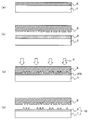
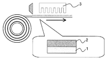
- the present disclosure describes a coating step of applying the above-mentioned photocurable resin composition for imprint to one main surface of a base material, and a coating surface of the above-mentioned photocurable resin composition for imprint of the base material.
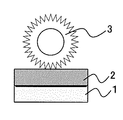
- a contact step of contacting a mold having an uneven structure on the surface and a state in which the mold and the base material are in contact with each other are irradiated with light to cure the photocurable resin composition for imprinting.
- a method for producing a pattern-forming body which comprises a curing step of forming a photocurable resin for imprint and a peeling step of peeling the mold from the photocurable resin for imprint on the surface of the base material. I will provide a.
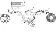
- a coating step of applying the above-mentioned photocurable resin composition for imprint to the surface of the mold having an uneven structure on the surface on the uneven structure side, and the above-mentioned photocurable resin composition for imprint of the mold In the contact step of bringing the base material into contact with the coated surface of the object, and in a state where the mold and the base material are in contact with each other, light is irradiated to cure the photocurable resin composition for imprinting.
- a method for producing a pattern-forming body which comprises a curing step of making a photocurable resin for printing and a peeling step of peeling the mold from the photocurable resin for imprint on the surface of the base material. provide. Since the above-mentioned photocurable resin composition for imprinting is used, it is possible to minimize the cleaning of the mold used, and efficient production can be performed.
- the present disclosure is a photocurable resin for imprint containing a siloxane bond, and is bonded to a single silicon atom among the oxygen atoms bonded to the silicon atom contained in the photocurable resin for imprint.
- a photocurable resin for imprint in which the proportion of oxygen atoms is 10 mol% or less. This is because by using such a photocurable resin for imprint as a resist, an antifouling effect on the mold can be exhibited.
- the present disclosure also provides a method for manufacturing an imprint mold, which comprises a step of etching the base material using the pattern-forming body obtained by the method for manufacturing the pattern-forming body as described above as a mask. Further, the present invention provides a method for manufacturing a device, which comprises a step of etching the base material using the pattern-forming body obtained by the method for manufacturing a pattern-forming body as described above as a mask.
- the imprint mold which is the original plate, can be washed well, so that efficient production is possible. Can be made possible.
- the present disclosure can provide a photocurable resin composition for imprints, which has a high antifouling effect on imprint molds and is excellent in stability over time.
- A. Photocurable Resin Composition for Imprint As described above, a polymerizable compound composed of a silicone resin having a polysiloxane bond in the molecule has been suitably used for nanoimprint applications because of its resist properties and the like.
- an oxygen atom is bonded to two silicon atoms.
- an oxygen atom bonded to a single silicon atom exists, for example, at the end of the polymer.
- Such an oxygen atom usually constitutes a highly reactive functional group having high reactivity such as -OH or -OR (R represents an alkyl group having 1 to 4 carbon atoms).
- R represents an alkyl group having 1 to 4 carbon atoms.
- the highly reactive functional group reacts during storage of the photocurable resin composition for imprint, and the polymerizable compound becomes high in molecular weight.
- the present invention has been completed by newly finding a point that hinders the storage stability of the curable resin composition.
- the photocurable resin composition for imprint of the present disclosure contains a polymerizable compound having a siloxane bond in the molecule and having at least one polymerizable functional group, and a photopolymerization initiator.
- the curable resin composition is characterized in that the proportion of oxygen atoms bonded to a single silicon atom among the oxygen atoms bonded to the silicon atoms contained in the polymerizable compound is 10 mol% or less. To do.
- the photocurable resin composition for imprinting of the present disclosure (hereinafter, may be simply referred to as a resin composition) will be described in detail.
- the polymerizable compound contained in the resin composition of the present disclosure is not particularly limited as long as it is a polymerizable compound having a siloxane bond in the molecule and having at least one polymerizable functional group.
- a polymer or oligomer having a tetrafunctional silane, a trifunctional silane, a bifunctional silane, and a monofunctional silane as a constituent unit can be used alone or in combination of two or more.
- etching resistance it is preferable to use a combination of mainly trifunctional silane and bifunctional silane as constituent units, depending on the properties desired for the resin composition such as etching resistance and viscosity.
- tetrafunctional silane may be contained for the purpose of improving etching resistance.
- the polymerizable compound used in the present disclosure is characterized in that the proportion of oxygen atoms bonded to a single silicon atom among the oxygen atoms bonded to the silicon atoms contained in the polymerizable compound is 10 mol% or less. Of these, 7 mol% or less, particularly preferably 5 mol% or less.
- the oxygen atom bonded to a single silicon atom means an oxygen atom in which one of the two hands of the oxygen atom is bonded to silicon, and both of the two hands of the oxygen atom are bonded to silicon. It means that it is not an oxygen atom bonded to a silicon atom.
- the other hand of the oxygen atom is not particularly limited as long as it is bonded to other than silicon, but it is particularly preferable that the other hand is bonded to hydrogen or an alkyl group having 1 to 4 carbon atoms.
- R indicates an alkyl group having 1 to 4 carbon atoms
- the stability of the resin composition with time can be improved, and the resin composition is formed on the mold surface. It is possible to prevent the resin composition from firmly adhering to the mold.
- the ratio of oxygen atoms bonded to a single silicon atom is defined as the ratio of oxygen atoms bonded to a single silicon atom when the number of oxygen atoms bonded to the silicon atom of the polymerizable compound is 100. It shows the number of oxygen atoms.
- the method for measuring this ratio can be calculated by analyzing the spectrum by 29 Si NMR.
- a component ⁇ in which none of the three oxygen atoms bonded to the silicon atom is bonded to another silicon atom 0
- one of the three oxygen atoms bonded to the silicon atom is bonded to the other silicon atom ⁇ 1
- two of the three oxygen atoms bonded to the silicon atom are bonded to the other silicon atom.
- four peaks of components T 3 that all three oxygen atoms bonded to the component T 2, and the silicon atom is bonded to other silicon atoms is observed.
- the composition contains a siloxane structure having a bifunctional silane as a constituent unit, all of the two oxygen atoms bonded to the silicon atom are bonded to the silicon atom, which is a component not bonded to the other silicon atom. Three peaks were observed: a component in which one of the two oxygen atoms is bonded to another silicon atom, and a component in which all of the two oxygen atoms bonded to the silicon atom are bonded to the other silicon atom. To.
- the composition contains a siloxane structure having a tetrafunctional silane as a constituent unit
- all four oxygen atoms bonded to the silicon atom are bonded to the silicon atom, which is a component not bonded to other silicon atoms.
- One of the four oxygen atoms is bonded to another silicon atom, and two of the four oxygen atoms bonded to the silicon atom are bonded to the other silicon atom, which is bonded to the silicon atom.
- Five peaks are observed in which three of the four oxygen atoms are bonded to other silicon atoms and all four oxygen atoms bonded to the silicon atom are bonded to other silicon atoms.
- the weight average molecular weight of the polymerizable compound is preferably in the range of 500 to 100,000, particularly preferably in the range of 600 to 50,000, and particularly preferably in the range of 700 to 20,000.
- the weight average molecular weight (Mw) is a polystyrene-equivalent molecular weight measured by gel permeation chromatography (GPC), and is a value measured under the following conditions after pressure filtration with a membrane filter having a filter pore size of 0.2 ⁇ m.
- the polymerizable functional group contained in the above-mentioned polymerizable compound is not particularly limited as long as it is a functional group capable of a polymerization reaction and the polymerization reaction proceeds by an external stimulus.
- a functional group capable of a polymerization reaction and the polymerization reaction proceeds by an external stimulus For example, light irradiation, Acryloyl group, metaacryloyl group, epoxy group, oxetane group, vinyl ether group and the like, in which the polymerization reaction proceeds due to the heat associated with light irradiation and the action of a photoacid generator, can be used. This is because such a polymerizable functional group has good stability during synthesis and storage, reactivity during curing, and easy availability of raw materials.
- acryloyl group and metaacryloyl group are particularly preferable from the viewpoint of curing speed and wide range of physical property selection.
- the polymerizable group directly bonded to the silicon atom in the polymerizable compound is bulky, the reactivity may change due to steric hindrance and affect the curability, etc., the polymerizable group directly bonded to the silicon atom may be affected.
- the molecular weight of is preferably in the range of 20 to 500, and more preferably in the range of 25 to 400.
- the polymerizable group means a group containing a polymerizable functional group. Preferred examples of such a polymerizable group include the structures shown below.
- R 1 means a substituted or unsubstituted alkyl chain having 1 to 10 carbon atoms
- R 2 means a substituted or unsubstituted alkyl chain having 1 to 3 carbon atoms, or a hydrogen atom.
- R 1 and R 2 may be linear or branched.
- At least one polymerizable functional group may be bonded to the constituent unit of the polymerizable compound, but the present invention is not limited to this, and two or more of the above-mentioned polymerizable functional groups may be bonded.
- Preferred examples of the structural unit having a photopolymerizable group of the polymerizable compound used in the present disclosure include the following.
- Bifunctional ones include, for example, 3-acryloxypropyl (methyl) dimethoxysilane, 3-acryloxypropyl (methyl) diethoxysilane, 3-methacryloxypropyl (methyl) dimethoxysilane, and 3-methacryloxypropyl.
- 3-acryloxypropyl (methyl) dimethoxysilane 3-acryloxypropyl (methyl) diethoxysilane, and 3-methacryloxypropyl (methyl) dimethoxysilane.
- a structural unit having no photopolymerizable group can be used in combination with a structural unit having a photopolymerizable group.
- trifunctional ones include trimethoxy (methyl) silane, triethoxy (methyl) silane, methyltripropoxysilane, tributoxy (methyl) silane, methyltriphenoxysilane, and ethyltri.
- trimethoxy (methyl) silane can be used, among which trimethoxy (methyl) silane. , Triethoxy (methyl) silane, ethyltrimethoxysilane, triethoxy (ethyl) silane, trimethoxy (phenyl) silane, triethoxy (phenyl) silane, cyclohexyltrimethoxysilane, cyclohexyltriethoxysilane and the like can be preferably used.
- dimethoxydimethylsilane, diethoxydimethylsilane, methylphenyldimethoxysilane, methylphenyldiethoxysilane, cyclohexyl (dimethoxy) methylsilane, cyclohexyldiethoxymethylsilane, dimethoxydiphenylsilane, diethoxydiphenylsilane , Dimethoxymethylvinylsilane, diethoxymethylvinylsilane and the like can be preferably used.
- the polymerizable compound in the present disclosure has a siloxane bond in the molecule, has at least one polymerizable functional group, and is a single oxygen atom bonded to a silicon atom contained in the polymerizable compound.
- the proportion of the oxygen atom bonded to the silicon atom of the above is 10 mol% or less
- the structure is not limited, and examples thereof include the first to third polymerizable compounds as illustrated below.
- the first polymerizable compound in the present disclosure contains bifunctional silane as a constituent unit in a molar amount larger than that of trifunctional silane. That is, it contains more structural units derived from bifunctional silane than those derived from trifunctional silane.
- a bifunctional silane as a constituent unit more than the trifunctional silane, high reactivity such as a residual -OH amount or a -OR amount (R indicates an alkyl group having 1 to 4 carbon atoms) can be obtained. It can be assumed that the amount of highly reactive functional groups to have is reduced. This is presumed to be for the following reasons.
- the structural unit derived from bifunctional silane is the above-mentioned cross-linking unit derived from bifunctional silane, and is a so-called D unit.
- the structural unit derived from trifunctional silane is the above-mentioned cross-linking unit derived from trifunctional silane, and is a so-called T unit.
- a single silicon atom among the oxygen atoms bonded to the silicon atom of the polymerizable compound can be selected by selecting the type and molar ratio of the bifunctional silane as a raw material or the trifunctional silane. The proportion of oxygen atoms bonded to is further reduced.
- Such a first polymerizable compound may contain only bifunctional silane as a constituent unit.
- the photopolymerizable group may be contained in at least one of the bifunctional silane and the trifunctional silane, but at least a part of the bifunctional silane is a photopolymerizable group. It is preferable to have (a group containing a polymerizable functional group). This is because it is possible to more reliably reduce the amount of highly reactive functional groups having high reactivity such as the amount of residual -OH or the amount of -OR.
- the content ratio of the photopolymerizable group and the like are appropriately determined according to the required conditions such as reactivity.
- trifunctional silane constituting the first polymerizable compound the one represented by the following formula (a) is preferable.
- bifunctional silane constituting the first polymerizable compound those represented by the following formula (b) are preferable.
- X 1 and X 2 are independently hydrogen atoms, substituted or unsubstituted alkyl groups, substituted or unsubstituted phenyl groups or the above-mentioned polymerizable groups, and R 10 and R 11 are independent of each other. , Hydrolyzable group. R 12 is an alkyl group.
- X 1 and X 2 are independently hydrogen atoms, substituted or unsubstituted alkyl groups, substituted or unsubstituted phenyl groups or the above-mentioned polymerizable groups, but are bifunctional silanes and trifunctional groups constituting the polymerizable compound. At least one of X 1 and X 2 contained in the functional silane is a polymerizable group.
- the polymerizable group of X 1 and X 2 can be the same as the polymerizable group described above, but X 1 is preferably an alkyl group or a polymerizable group having a relatively small bulk, and specifically has a molecular weight. Groups of 1 to 400 are preferred, with particular preference being 3-acryloxypropyl groups and 3-methacryloxypropyl groups.
- the X 2 preferably has a relatively bulky alkyl group or a polymerizable group, specifically groups having a molecular weight of from 1 to 700 is preferred, particularly preferably a 3-meth Lilo carboxypropyl group.
- X 1 is a relatively bulky hydrogen atom, a substituted or unsubstituted alkyl group, a substituted or unsubstituted phenyl group or a polymerizable group
- the remaining unreacted oxygen atom is further reduced. Will be done.
- X 2 is a relatively bulky alkyl group or polymerizable group, the stability of the polymerizable compound can be improved by inhibiting the reaction of the remaining unreacted oxygen atoms.
- R 10 and R 11 include an alkoxy group having 1 to 4 carbon atoms, and preferably a methoxy group and an ethoxy group.
- R 12 for example, a methyl group or the like is preferable.
- the ratio (molar ratio) of these is preferably 100: 0 to 51:49.
- the siloxane usually has a branched chain structure. Further, the siloxane unit in parentheses with n and the siloxane unit in parentheses with m may be randomly arranged with each other or arranged in blocks.
- the first polymerizable compound can be synthesized by the method described later.
- the polymerizable compound has a spherical structure.
- the polymerizable compound having a spherical structure include those having a trifunctional silane as a constituent unit. Of these, those containing only trifunctional silane as a constituent unit are preferable.
- the second polymerizable compound having such a spherical structure is, for example, one or more of a hexamer to a 36-mer (molecular weight 1000 or more and 6300 or less) of a trifunctional silane having a polymerizable functional group. Examples include mixtures.
- a siloxane composed of such a trifunctional silane usually has a structure in which a polymerizable functional group extends outward, centering on a siloxane polymerized portion having a high degree of siloxane polymerization consisting of 3/2 units of SiO.
- a polymerizable compound having a spherical structure has a siloxane polymerization degree of more than 90% in the siloxane polymerization part, and can be particularly 95% or more. Therefore, the oxygen atom bonded to the silicon atom contained in the polymerizable compound Of these, the proportion of oxygen atoms bonded to a single silicon atom is 10 mol% or less.
- spherical structure represented by the following formula.
- the following formulas are diagrams showing a polymerizable compound having a spherical structure, each consisting of an octamer of a trifunctional silane having an acryloxipropyl group and a 3-methacryloxypropyl group as polymerizable groups.
- SiO 1.5 indicates a siloxane polymerized portion composed of 3/2 units of SiO.
- examples of the polymerizable compound in the present disclosure include a polyhedron siloxane oligomer having a completely or incompletely condensed skeleton to which a polymerizable functional group is bonded. Since such a third polymerizable compound has a regular structure, the ratio of the oxygen atoms bonded to a single silicon atom among the oxygen atoms bonded to the silicon atoms contained in the polymerizable compound is high. It is 10 mol% or less.
- a polyhedron siloxane oligomer having a completely condensed skeleton to which polymerizable functional groups are bonded has a cubic apex with a silicon atom and an oxygen atom in between, specifically, the formula (R 15 SiO 1.5 ).
- n (n is 6, 8, 10, 12 or 14, and R 15 is a polymerizable group containing a polymerizable functional group), or an expression in which a polymerizable group R 16 containing a polymerizable functional group is bonded.
- SiO 2 n has a structure represented by (n is 6, 8, 10, 12 or 14). In particular, those represented by the following formulas are preferable.
- R 15 and R 16 are polymerizable groups.
- the polyhedral siloxane oligomer having an incompletely condensed skeleton to which a polymerizable functional group is bonded the above (R 15 SiO 1.5 ) n structure, one vertex of the above (SiO 2 ) n structure, Examples thereof include an incomplete condensation type in which one side or one surface is missing, and the one represented by the following formula is particularly preferable.
- R 18 is bonded to the oxygen atom in the formula-Si-polymerizable group, hydrogen atom, metal ion such as Na, Li, or tetraalkylammonium ion (the alkyl group is methyl, ethyl, propyl, butyl). Etc.), and R 17 is a monovalent hydrocarbon group.
- R 17 is a monovalent hydrocarbon group, preferably an alkyl group having 1 to 5 carbon atoms, a phenyl group, and specifically, an ethyl group, a butyl group, and a phenyl group.
- a polyhedron siloxane oligomer having a completely or incompletely condensed skeleton to which such polymerizable functional groups are bonded has a small molecular size and easily enters the gaps of fine patterns. Therefore, it is a photocurable resin for nanoimprinting. It is useful as a composition.
- a composition containing an incompletely condensed polyhedral siloxane oligomer to which a polymerizable functional group is bonded is preferable because the viscosity is lowered.
- a photopolymerization initiator is a substance that generates a reactive species that causes a polymerization reaction of a polymerizable compound by photostimulation. Specific examples thereof include a photoradical generator that generates radicals by photostimulation, a photoacid generator that generates protons by photostimulation, and the like.
- the photoradical generator is a polymerization initiator that generates radicals by light (radiation such as charged particle beams such as infrared rays, visible rays, ultraviolet rays, far ultraviolet rays, X rays, and electron beams), and is mainly composed of polymerizable compounds. Used in the case of radically polymerizable compounds.
- the photoacid generator is a polymerization initiator that generates an acid (proton) by light, and is mainly used when the polymerizable compound is a cationically polymerizable compound.
- Examples of the photoradical generator include 2,4,6-trimethyldiphenylphosphine oxide, 2,2-dimethoxy-2-phenylacetophenone, 2-methyl-1- [4- (methylthio) phenyl] -2-. Morphorino-Propane-1-one, 2-benzyl-2-dimethylamino-1- (4-morpholinophenyl) -1-butanone, 2- (dimethylamino) -2-[(4-methylphenyl) methyl]- 1- [4- (4-morpholinyl) phenyl] -1-butanone, 2-hydroxy-2-methyl-1-phenyl-propane-1-one, 2-hydroxy-2-methyl-1-phenyl-propane-1 -On, etc., but not limited to these.
- One type of these photoradical generators may be used alone, or two or more types may be used in combination.
- photoacid generator examples include, but are not limited to, onium salt compounds, sulfone compounds, sulfonic acid ester compounds, sulfonimide compounds, and diazomethane compounds.
- the content of the photopolymerization initiator in the resin composition of the present disclosure is not particularly limited, and may be in the range of 0.5% by mass to 20% by mass with respect to the above-mentioned polymerizable compound. It can be in the range of 1% by mass to 10% by mass.
- the resin composition of the present disclosure may contain any ingredient other than the above-mentioned polymerizable compound and photopolymerization initiator.
- a surfactant such as a fluorine-based surfactant, a hydrocarbon-based surfactant, or a silicone-based surfactant may be contained for the purpose of improving the releasability from the imprint mold, and among them, a fluorine-based surfactant.
- Surfactants and silicone-based surfactants can be preferably used. This is because it is easy to segregate the surface and reduce the mold release force.
- fluorine-based surfactant examples include a polyalkylene oxide (polyethylene oxide, polypropylene oxide, etc.) adduct of an alcohol having a perfluoroalkyl group, a polyalkylene oxide (polyethylene oxide, polypropylene oxide, etc.) adduct of perfluoropolyether, and the like. Can be mentioned.
- the fluorine-based surfactant may have a hydroxyl group, an alkoxy group, an alkyl group, an amino group, a thiol group or the like in a part of the molecular structure (for example, a terminal group).
- examples of the silicone-based surfactant include a polydimethylsiloxane derivative having a polymerizable group such as an acryloyl group, a metaacryloyl group, an epoxy group, an oxetane group, and a vinyl ether group.
- the silicone-based surfactant may have a hydroxyl group, an alkoxy group, an alkyl group, an amino group, a thiol group, or the like in a part of the molecular structure (for example, a terminal group).
- the content of such a fluorine-based surfactant is not particularly limited, but can be, for example, 10% by mass or less, particularly 5% by mass or less, based on the total solid content of the resin composition. If the content is too small, the effect of improving releasability may not be sufficiently obtained, and if the content is too large, problems such as changes in the dimensions of the uneven pattern shape and bleeding may occur. is there.
- the resin composition may contain a solvent for the purpose of adjusting its viscosity and the like.
- a solvent for the purpose of adjusting its viscosity and the like.
- organic pigments, inorganic pigments, extender pigments, organic fillers, inorganic fillers, photosensitizers, ultraviolet absorbers, antioxidants, polymerization inhibitors, surfactants, adhesion aids It is also possible to contain an agent or the like.
- the method for producing a photocurable resin composition for imprint in the present disclosure is not particularly limited as long as it can produce a desired one.
- it can be produced by the production method described in "B. Method for producing a photocurable resin composition for imprint" described later.
- the highly reactive functional group is not particularly limited as long as it is -OH or -OR (R indicates an alkyl group having 1 to 4 carbon atoms), but the reactivity is high. The higher the value, the more remarkable the action and effect of the present invention will be exhibited. Therefore, it is preferably -OH or -OR (R indicates an alkyl group having 1 to 2 carbon atoms), and particularly preferably -OH. Is.
- the method for producing the photocurable resin composition for imprint of the present disclosure is a polymerizable compound having a siloxane bond in the molecule and having at least one polymerizable functional group.
- a method for producing a photocurable resin composition for imprint which comprises producing a photocurable resin composition for imprint containing a photopolymerization initiator, and in the molecule in order to obtain the above-mentioned polymerizable compound. Higher than the above, with respect to a highly reactive polymerizable compound having a siloxane bond, having at least one polymerizable functional group, and having a highly reactive functional group containing an oxygen atom bonded to a single silicon atom. It is characterized by having a stabilizing step of adding a protective agent containing a protective group for protecting the reactive functional group.
- the curable resin composition containing a siloxane bond in the molecule produced by the conventional production method has a high proportion of highly reactive functional groups having an oxygen atom bonded to a single silicon atom, and thus the above-mentioned resin.
- the composition is inferior in stability over time, and when such a resin composition is used as a resist material in imprint lithography, the resin composition adheres to the imprint mold, making it difficult to keep the imprint mold clean. Met.
- a protective agent is added to react the protecting group with the highly reactive functional group to reduce the proportion of the highly reactive functional group, thereby achieving the above-mentioned action and effect.
- a resin composition that plays a role is produced.
- a monofunctional functional group particularly a monofunctional silane is preferable.
- a monofunctional silane compound is preferable, and since it is particularly highly reactive, a protective agent having a halogen atom at the terminal is preferable, and specifically, the following formula (1) ) Can be mentioned.
- X in the formula is a halogen atom
- R 1 to R 3 can be alkyl groups having 1 to 5 carbon atoms, respectively.
- X is chlorine
- R 1 to R 9 are preferably alkyl groups having 1 to 2 carbon atoms, respectively.
- the protective agent may be a protective agent that decomposes and has a function as the above-mentioned protecting group.
- a compound represented by the following formula (2) can be mentioned.
- R 4 to R 9 can be alkyl groups having 1 to 5 carbon atoms, respectively. In this case as well, a smaller number of carbon atoms is preferable from the viewpoint of reactivity, but an alkyl group having a large number of carbon atoms may be partially used in consideration of compatibility with the above-mentioned polymerizable compound. In the present disclosure, it is preferable that R 4 to R 9 are alkyl groups having 1 to 2 carbon atoms, respectively.
- HSi (R 10 ) 3 can also be used (R 10 is an alkyl group having 1 to 2 carbon atoms, and all of them may be the same or different).
- R 10 is an alkyl group having 1 to 2 carbon atoms, and all of them may be the same or different.
- a catalyst for example, tris (pentafluorophenyl) borane or the like can be used.
- the stabilization step in the present disclosure is a step of adding and diffusing the protective agent to a resin composition containing the highly reactive polymerizable compound to cause a reaction, or the highly reactive step of the composition containing the protective agent.
- This is a step of adding and diffusing a resin composition containing a polymerizable compound.
- heating or the like may be performed as necessary, or a catalyst or the like may be added.
- the amount of the protective agent added is appropriately determined by the amount of highly reactive functional groups contained in the polymerizable compound contained in the resin composition.
- the protective material having a molar ratio of 0.5 to 100 times, preferably 0.7 to 50 times, more preferably 0.8 to 25 times the amount of the highly reactive functional group obtained by the above method. Is added.
- the proportion of the highly reactive functional groups can be reduced to 10 mol% or less, particularly 7 mol% or less. preferable. Since the method for calculating the ratio is the same as that described in the above-mentioned "A. Photocurable resin composition for imprinting", the description thereof is omitted here.
- an oxygen atom bonded to a single silicon atom is synthesized by synthesizing the polymerizable compound as in the following first synthesis step to third synthesis step. ) Is reduced, in particular, a polymerizable compound reduced to 10 mol% or less can be directly obtained.
- (1) First Synthesis Step In the first synthesis step, one or more types of bifunctional silanes and, if necessary, one or more types of other hydrolyzable silanes are used, and at least the bifunctional silanes are trifunctional.
- a hydrolyzable silane composition which is blended so as to be contained in a larger molar amount than silane and in which at least a part of the above bifunctional silanes has the above polymerizable functional group is hydrolyzed and condensed under acidic conditions. This is a step of obtaining a polymerizable compound by reacting.
- a solvent and silane as a raw material can be carried out by charging a solvent and silane as a raw material into a reactor, adding an acid as a catalyst, and dropping water while stirring.
- the acid catalyst include hydrochloric acid, sulfuric acid, phosphoric acid, nitric acid, acetic acid and the like, and the pH is 1 to 6, which can be typically carried out at room temperature.
- the silane used as the raw material one or more types of bifunctional silane and one or more type of other hydrolyzable silane (particularly preferably trifunctional silane) are used, if necessary. At least a part of the bifunctional silane has a polymerizable functional group, and the bifunctional silane is particularly preferably one represented by the above formula (b).
- the trifunctional silane may or may not contain a polymerizable functional group, and examples thereof include those represented by the above formula (a).
- the proportion of oxygen atoms bonded to a single silicon atom among the oxygen atoms bonded to the silicon atoms contained in the polymerizable compound was reduced, particularly to 10 mol% or less.
- the polymerizable compound can be easily obtained. Specifically, the above-mentioned first polymerizable compound can be produced.
- a hydrolyzable silane composition containing at least a hydrolyzable silane is hydrolyzed and condensed under basic conditions to obtain a polymerizable compound. This is a compound synthesis step.
- a solvent and silane as a raw material can be carried out by charging a solvent and silane as a raw material into a reactor, adding a basic substance as a catalyst, and dropping water while stirring.
- basic catalysts include sodium hydroxide, potassium hydroxide, lithium hydroxide, potassium carbonate (K 2 CO 3), sodium carbonate, ammonia and the like, and PH8 ⁇ 13, it is typically carried out at room temperature be able to.
- the silane used as the raw material may be any one or more of tetrafunctional hydrolyzable silane, trifunctional hydrolyzable silane, bifunctional hydrolyzable silane, and monofunctional hydrolyzable silane. It is preferable to use a tetrafunctional hydrolyzable silane or a trifunctional hydrolyzable silane. Further, only one type of hydrolyzable silane may be used, or two or more types may be used in combination.
- the polymerizable compound obtained in the hydrolysis condensation reaction has a high degree of condensation. Therefore, it is possible to easily obtain a polymerizable compound in which the proportion of oxygen atoms bonded to a single silicon atom among the oxygen atoms bonded to the silicon atom is reduced, particularly to 10 mol% or less. .. Specifically, it becomes possible to produce a polymerizable compound having a spherical structure, such as the second polymerizable compound described above.
- the third synthesis step is a polyhedron having a completely or incompletely condensed skeleton in which an organic group other than a hydrogen atom, a hydroxy group, or a polymerizable functional group is bonded to a silicon atom.
- This is a step of synthesizing a polymerizable compound to obtain the above-mentioned polymerizable compound by reacting a siloxane oligomer with a polymerizable functional group-containing compound.
- the raw material a polyhedron siloxane oligomer having a completely or incompletely condensed skeleton, is a silicon atom located at the apex in which an organic group other than a hydrogen atom, a hydroxy group, or a polymerizable functional group is bonded.
- Examples of the organic group other than the polymerizable functional group include an alkoxy group, an alkyl group, a phenyl group and the like.
- Examples of the reaction between the above raw materials and the polymerizable functional group-containing compound include conventionally known reactions.
- an addition reaction between a hydrogen atom directly linked to silicon and a polymerizable functional group-containing compound having an unsaturated double bond, or a polymerization capable of forming a siloxane bond with an OH group or OR group directly linked to silicon examples include a reaction with a sex functional group-containing compound.
- the method for producing a pattern-forming body of the present disclosure includes a coating step of applying the above-mentioned photocurable resin composition for imprint to one main surface of a base material, and the above-mentioned imprint of the above-mentioned base material.
- a contact step in which a mold having an uneven structure on the surface is brought into contact with the coated surface of the photocurable resin composition for use, and light is irradiated in a state where the mold and the base material are in contact with each other for the above-mentioned imprint. It has a curing step of curing the photocurable resin composition to obtain a photocurable resin for imprint, and a peeling step of peeling the mold from the photocurable resin for imprint on the surface of the base material. It is characterized by.
- FIG. 1 shows an example of a method for producing a pattern-forming body of the present disclosure.
- the resin composition described in the section of "A. Photocurable resin composition for imprinting" is applied to one surface of the base material 1, and the resin composition is prepared. Form 2 layers (coating step).
- the imprint mold 3 is brought into contact with the coated surface of the resin composition 2, and the resin composition 2 is filled in the uneven structure of the imprint mold 3. Let (contact process).
- FIG. 1A first, the resin composition described in the section of "A. Photocurable resin composition for imprinting" is applied to one surface of the base material 1, and the resin composition is prepared. Form 2 layers (coating step).
- the imprint mold 3 is brought into contact with the coated surface of the resin composition 2, and the resin composition 2 is filled in the uneven structure of the imprint mold 3. Let (contact process).
- FIG. 1A shows an example of a method for producing a pattern-forming body of the present disclosure.
- the resin composition is cured by irradiating light 4 to cure the imprint photocurable resin 5.
- the imprint mold 3 is peeled off from the imprint photocurable resin 5 to form a pattern having an uneven pattern made of the imprint photocurable resin 5.
- Obtain body 10 peeleling step).
- the mold can be easily cleaned and can be manufactured at low cost. Therefore, a high-definition pattern-forming body can be manufactured.
- each step of the pattern forming body of the present disclosure will be described.
- the coating step in the present disclosure is a step of coating the above-mentioned resin composition on one main surface of the base material.
- the resin composition applied in this step is the same as that described in the above-mentioned "A. Photocurable resin composition for imprinting", and thus the description thereof is omitted here.
- the base material in the present disclosure is not particularly limited in shape, such as a plate-like material, a film-like material, a sheet-like material, or a rectangular parallelepiped material.
- the base material is not particularly limited as long as it can support the coating layer of the resin composition, and the presence or absence of transparency, the presence or absence of smoothness, and the like are not particularly limited.
- Specific examples of the material of the base material include silicone materials such as quartz, glass, silicon, sapphire, diamond, and polydimethylsiloxane, fluororesins, cycloolefin resins, and other resin materials.
- the shape of the base material is not particularly limited, and examples thereof include a circular shape and a rectangular shape.
- the thickness of the base material varies depending on the material, application, and the like, but can be, for example, in the range of 0.001 mm to 10 mm. At least a part of the surface of such a base material may be treated with a metal oxide, such as the formation of a metal oxide film.
- the method of applying the resin composition onto the substrate is not particularly limited as long as it can be applied smoothly, and for example, a spin coating method, a spray method, a bar coating method, an inkjet method, and the like.
- General coating methods such as dip method, roll coating method, blade coating method, doctor roll method, doctor blade method, curtain coating method, slit coating method, and screen printing method can be used, among which spin coating method and spray method can be used.
- the method, the bar coating method, and the inkjet method can be preferably used.
- the contact step in the present disclosure is a step of bringing a mold having an uneven structure on the surface into contact with the coated surface of the resin composition of the base material.
- the imprint mold is not particularly limited as long as it has an uneven pattern to be transferred, and a mold generally used in imprint lithography can be used.
- the material of the imprint mold in the present disclosure is not particularly limited as long as it has a Si atom on the surface in contact with the resin, and examples thereof include quartz, glass, silicon, and silicone resin. This is because the advantages of the resin composition can be effectively obtained by using such an imprint mold.
- the resin composition is filled in the uneven structure of the imprint mold by bringing the imprint mold into contact with the resin composition.
- the mold and the base material are in contact with each other and irradiated with light to cure the photocurable resin composition for imprint, and the photocurable resin for imprint is cured.
- the above-mentioned light irradiation is usually performed from the back surface (the surface on which the pattern is not formed) side of the imprint mold, but for example, when the base material is transparent and the imprint mold is opaque, the base material side. It may be irradiated from.
- the light to be irradiated is appropriately selected according to the sensitivity wavelength of the photocurable resin composition for imprint, and for example, ultraviolet rays having a wavelength in the range of 150 nm to 400 nm, X-rays, electron beams, etc. may be used. It is possible, and ultraviolet rays are particularly preferably used.
- the light source that emits ultraviolet rays include high-pressure mercury lamps, ultra-high pressure mercury lamps, low-pressure mercury lamps, Deep-UV lamps, carbon arc lamps, chemical lamps, metal halide lamps, xenon lamps, KrF excimer lasers, ArF excimer lasers, and F2 excimer lasers.
- the ultra-high pressure mercury lamp is particularly preferable.
- the peeling step in the present disclosure is a step of peeling the mold from the photocurable resin for imprint on the surface of the base material.
- the peeling method is not particularly limited as long as it does not damage the uneven pattern of the formed photocurable resin for imprinting, and a general method such as moving one of them for the purpose of peeling is used. Can be used.
- FIG. 1 shows a diagram in which a flat plate is used as the base material 1 and a flat plate having an uneven pattern is used as the imprint mold 3 to obtain a pattern forming body 10, but the base material is a film.
- a roll-shaped product or an imprint mold can also be preferably used.
- the embodiments shown in FIGS. 3 to 5 can be mentioned.
- FIG. 3 is a diagram when a flat plate is used as the base material 1 and a roll mold having an uneven pattern is used as the imprint mold 3.
- the imprint mold and the base material are brought into contact with each other to fill the uneven structure of the imprint mold with the resin composition, and the resin composition is cured by irradiating light to cure the imprint light.
- a curable resin is used, and the imprint mold 3 is peeled off from the imprint photocurable resin according to the rotation of the mold to obtain a pattern-forming body.
- FIG. 4 is a diagram when a film-like material is used as the base material 1 and a flat plate having an uneven pattern is used as the imprint mold 3.
- the base material 1 of the film is taken out from the rolled state, the resin composition 2 is applied to the taken out base material 1, and the imprint mold 3 is brought into contact with the coated surface of the resin composition. ..
- the resin composition is cured by irradiating light to obtain a photocurable resin for imprint, and the photocurable resin for imprint is used for imprint.
- the mold 3 is peeled off to obtain a pattern-forming body.
- FIG. 5 is a diagram when a film-like base material 1 is used and a roll mold having an uneven pattern is used as the imprint mold 3.
- the base material 1 of the film is taken out from the rolled state, the resin composition 2 is applied to the taken out base material 1, and the roll mold 3 having an uneven pattern on the coated surface of the resin composition.
- the mold 3 and the base material 1 are in contact with each other, light is irradiated from the ultraviolet irradiation lamp 50 to cure the resin composition to obtain a photocurable resin for imprint, and a photocurable resin for imprint.
- the imprint mold 3 is peeled off in accordance with rotation to obtain a pattern forming body 10 having an uneven pattern made of the above-mentioned imprint photocurable resin.
- the installation position of the ultraviolet irradiation lamp 50 is not particularly limited.
- the roll mold 3 is transparent and the base material 1 is opaque, it is installed in the mold (ultraviolet irradiation lamp 50B in FIG. 5).
- the roll mold 3 is opaque and the base material is transparent, it can be installed outside the mold (ultraviolet irradiation lamp 50A in FIG. 5).
- the method for producing a pattern-forming body in the present disclosure may be the following aspects in addition to the above-described aspects. That is, the method for producing the pattern-forming body of this embodiment includes a coating step of applying the above-mentioned photocurable resin composition for imprint to the surface of a mold having an uneven structure on the surface and the above-mentioned molding. The contact step of bringing the base material into contact with the coated surface of the photocurable resin composition for imprint, and the photocuring for imprint by irradiating light with the mold and the base material in contact with each other.
- the method for producing the pattern-forming body of this embodiment is different from the above-described embodiment in that the resin composition is applied to the surface of the mold on the uneven structure side in the coating step. Since the above-described embodiment and the present embodiment are the same except that the coating surface in the coating step is different, the description thereof is omitted here.
- the photocurable resin for imprint of the present disclosure is a photocurable resin for imprint containing a siloxane bond, and is bonded to a silicon atom contained in the photocurable resin for imprint. It is characterized in that the ratio of the oxygen atom bonded to a single silicon atom is 10 mol% or less among the oxygen atoms.
- the ratio of oxygen atoms (unreacted oxygen atoms) bonded to a single silicon atom among the oxygen atoms bonded to the silicon atoms contained in the photocurable resin for imprint is determined. It is 10 mol% or less, and more preferably 7 mol% or less, particularly 5 mol% or less.
- the method for calculating the ratio of unreacted oxygen atoms is the same as that described in the section “A. Photocurable resin composition for imprinting” described above, and thus the description thereof is omitted here.
- the above-mentioned photocurable resin for imprint is not particularly limited as long as it contains a siloxane bond in which an oxygen atom is bonded to two silicon atoms and the ratio of unreacted oxygen atoms is within a predetermined range.
- it can be obtained by curing the photocurable resin composition for imprint described in the section "A.
- Photocurable resin composition for imprint and is photocurable for imprint.
- the resin composition is a pattern-forming body obtained by curing in a pattern.
- the method for producing the cured photocurable resin for imprint is not particularly limited, and for example, it can be produced by the method described in the section "C. Method for producing a pattern-forming body". ..
- the manufacturing method of the imprint mold of the present disclosure is characterized by including a step of etching the base material using the pattern forming body obtained in the above "C. Manufacturing method of pattern forming body" as a mask. Is to be.
- a print mold can be manufactured.
- the imprint mold manufactured by such a method for manufacturing an imprint mold is not particularly limited as long as it can be used as a transfer original plate in imprint lithography, and is usually one of flat substrates. It has an uneven transfer pattern on the main surface of the surface.
- FIG. 2 is a schematic cross-sectional view showing an example of an imprint mold manufactured by the imprint mold manufacturing method of the present disclosure.
- the imprint mold 20 includes a base 21 and a mold substrate 23 having a mesa structure 22 provided on the main surface 21a of the base 21, and the main surface 22a of the mesa structure 22 has irregularities.
- a transfer pattern 24 of the structure is provided.
- an alignment mark pattern 25 having a concavo-convex structure is provided in order to align the imprint mold 20 with the transferred body.
- a recess 26 including the mesa structure 22 is provided on the surface of the base 21 opposite to the main surface 21a in a plan view.
- the method for producing the imprint mold of the present disclosure is not particularly limited as long as the pattern-forming body obtained in the above-mentioned "C. Method for producing a pattern-forming body" is used as a mask. Can have a process.
- the imprinted mold manufacturing method of the present disclosure may include a molding substrate preparation step of preparing a molding substrate for forming a transfer pattern.
- the molding substrate is not particularly limited as long as it can form a transfer pattern on the molding substrate, and for example, a plate-shaped substrate can be used.
- the molding substrate may have a mesa structure in which a step is formed on a portion of the surface where the imprint mold is in contact with the resin layer to be transferred, where an uneven pattern is formed. By having the mesa structure that limits the area to which the material to be transferred is applied, it is possible to limit the area where the resin layer to be transferred is wet and spread.
- the mold substrate may or may not have a recess on the surface opposite to the transfer pattern.
- a recess By providing such a recess, when the transfer pattern of the imprint mold is brought into close contact with the curable resin layer applied to the surface of the object to be transferred, the air pressure in the recess is increased to bend the imprint mold. Therefore, the starting point at which the transfer pattern first contacts the curable resin layer can be limited. Further, at the time of mold release, the portion where the peeling starts can be limited by bending the recess, and the defect at the time of mold release can be suppressed by peeling slowly and smoothly from the end of the mesa.
- the molding substrate is not particularly limited as long as it can form an uneven pattern, and may be one that transmits the irradiated light or one that blocks the light. If the light to be irradiated is transmitted, the light can be irradiated from the molding substrate side, and if the light to be irradiated is blocked, the light to be irradiated by the base material is transmitted. If it is, the light can be irradiated from the base material side.
- Examples of the material of such a substrate for molding include semiconductors such as silicon (Si), gallium nitride (GaN) and gallium arsenic (GaAs), glass such as quartz and soda lime glass, nickel (Ni) and aluminum ( Examples thereof include metals such as Al), ceramics such as silicon nitride (SiN), silicon oxide (SiO2) and silicon carbide (SiC), diamonds, diamond-like carbon (DLC) and cubic boron nitride (CBN). Of these, quartz, crow, and silicon (Si) are preferable from the viewpoint of being able to process finer dimensions.
- Such a molding substrate preferably has a light transmittance of 85% or more in the wavelength range of 300 nm to 450 nm, for example. Further, at least a part of the surface of the molding substrate may be treated with a metal oxide such that a metal oxide film is formed.
- Transfer pattern forming step In the method for producing an imprint mold of the present disclosure, a photocurable resin pattern for imprint formed by curing a photocurable resin composition for imprint is formed on the molding substrate, and the inprint is formed. It may have a transfer pattern forming step of etching a photocurable resin pattern for printing as a mask to form a transfer pattern.
- etching the molding substrate on which the pattern of the photocurable resin for imprint is formed is not particularly limited, and etching can be performed by a conventionally known method, for example, dry etching.
- the gas used for dry etching can be appropriately selected depending on the elemental composition of the molding substrate.
- an oxygen atom-containing gas such as oxygen, carbon monoxide, carbon dioxide, an inert gas such as helium, nitrogen, or argon, Chlorine-based gas such as chlorine and boron trichloride, fluorine gas, fluorocarbon-based gas, hydrogen gas, ammonia gas and the like can be used. These gases may be used alone or in admixture.
- the transfer pattern formed in this step is a pattern having a concavo-convex structure when the molding substrate is viewed in cross section, and is a pattern transferred to the transferred body.
- the shape of the transfer pattern is not particularly limited, and examples thereof include a pattern having an uneven structure such as a line and space, a dot, a hole, an isolated space, an isolated line, a pillar, a lens, and a step.
- the device manufacturing method of the present disclosure is characterized by including a step of etching the base material using the pattern forming body obtained in the above "C. Manufacturing method of pattern forming body" as a mask. is there. According to the present disclosure, it is possible to manufacture a high-definition device having good manufacturing efficiency.
- the method for manufacturing such a device is not particularly limited as long as the pattern-forming body obtained in the above-mentioned "C. Method for manufacturing a pattern-forming body" is used as a mask.
- the device manufacturing method of the present disclosure is the same as the above-mentioned imprint mold manufacturing method except that various devices are used depending on the device from which the base material to be used is obtained, and thus the description thereof is omitted here. To do.
- the device manufactured in the present disclosure is not particularly limited as long as it requires the formation of a fine pattern in the manufacturing process.
- a semiconductor device an optical element (diffraction grating, a polarizing element, etc.), a wiring circuit, etc.
- Data storage media hardware, optical media, etc.
- medical components analytical inspection chips, microneedles, etc.
- biodevices biosensors, cell culture substrates, etc.
- precision inspection equipment components inspection probes, sample holding members, etc.
- the present invention is not limited to the above embodiment.
- the above embodiment is an example, and any one having substantially the same configuration as the technical idea described in the claims of the present invention and exhibiting the same effect and effect is the present invention. It is included in the technical scope of the invention.
- Example 1 Chlorotrimethylsilane was used as a protective agent for the polymerizable compound 1 to protect the highly reactive functional groups of the above-mentioned polymerizable compound.
- the treatment with chlorotrimethylsilane was carried out as follows. 5 g of polymerizable compound 1 was dissolved in 20 mL of tetrahydrofuran, 5.34 g of chlorotrimethylsilane was added thereto, and the mixture was refluxed for 1 hour. After adding 1.7 g of methanol and stirring for 10 minutes, the volatile component was removed to obtain a polymerizable compound 3.
- a photocurable resin composition was obtained by dissolving 0.01 g of Irgacure 907 as a photopolymerization initiator in 1 g of the polymerizable compound 3.
- the imprint photocurable resin composition thus obtained is bonded to a single silicon atom by the method described in the above-mentioned "A. Imprint photocurable resin composition”.
- the proportion of oxygen atoms was calculated. The results are shown in Table 1.
- Example 2 A photocurable resin composition for imprinting was obtained in the same manner as in Example 1 except that the mixture was stirred at room temperature for 30 minutes after the addition of chlorotrimethylsilane, and the proportion of unreacted oxygen atoms was determined by the same method as in Example 1. Calculated. The results are shown in Table 1.
- Example 3 Example 2 except that the polymerizable compound 2 was used instead of the above-mentioned polymerizable compound 1 and 3.79 g of chlorotrimethylsilane was used instead of 5.34 g of chlorotrimethylsilane to obtain the polymerizable compound 4 shown below.
- a photocurable resin composition for imprint was obtained in the same manner as in Example 1, and the proportion of unreacted oxygen atoms was calculated by the same method as in Example 1. The results are shown in Table 1.
- Example 1 A photocurable resin composition for imprinting was obtained in the same manner as in Example 1 except that the above-mentioned polymerizable compound 2 was used as it was as the polymerizable compound in Comparative Example 1 without being treated with chlorotrimethylsilane. , The ratio of unreacted oxygen atoms was calculated by the same method as in Example 1. The results are shown in Table 1.
- the antifouling property was evaluated using the photocurable resin composition for imprint produced in Examples 1 to 3 and Comparative Examples 1 and 2. Specifically, a photocurable resin composition for imprinting is applied on a substrate made of quartz, and in contact with an imprinting mold made of quartz, light is irradiated under the conditions of 20mWcm-2,250sec. The photocurable resin composition for imprint was cured, the imprint mold was peeled off, and a pattern was formed on the substrate. After repeating such a pattern forming step 5 times, the light transmittance of the imprint mold after use was measured.
- the light transmittance was measured at a wavelength of 220-400 nm using an ultraviolet-visible spectrophotometer UV-2700 manufactured by Shimadzu Corporation.
- the antifouling property was evaluated by comparing the light transmittance of the imprint mold after use with the light transmittance before use and the amount of change thereof.
- the light transmittance of the imprint mold before use was 93%.
- the stability over time was evaluated using the photocurable resin compositions for imprint produced in Examples 1 to 3 and Comparative Examples 1 and 2. Specifically, the viscosity of each photocurable resin composition for imprint is measured after production (before storage), and then stored at 25 ° C., 40% RH, in a dark place for 30 days, and then before storage. The viscosity was measured by the same measuring method as above, and the amount of change in viscosity before and after storage was examined. The viscosity was measured using the following equipment under the following conditions.
- Viscosity change before and after storage is less than 2%
- Viscosity change before and after storage is 2% or more and 5% or less
- Viscosity change before and after storage is 5% or more and 10% or less
- Storage The amount of change in viscosity before and after is over 10%
- the photocurable resin compositions for imprinting of Examples 1 to 3 had good antifouling properties and stability over time.
- the photocurable resin composition for imprint of Comparative Example 1 in which the proportion of unreacted oxygen atoms was higher than that of Example 3 had a slight change in light transmittance and a slight change in viscosity.
- the photocurable resin composition for imprint of Comparative Example 2 in which the proportion of unreacted oxygen atoms was higher than that of Comparative Example 1 the amount of change in both the light transmittance and the viscosity was large.
- Example 4 0.01 g of Irgacure 907 as a photopolymerization initiator was dissolved in 1 g of the polymerizable compound 5 to obtain a photocurable resin composition.
- the imprint photocurable resin composition thus obtained is bonded to a single silicon atom by the method described in the above-mentioned "A. Imprint photocurable resin composition”.
- the proportion of oxygen atoms was calculated.
- Antifouling evaluation and temporal stability evaluation were performed in the same manner as in Examples 1 to 3. The results are shown in Table 2.
- Example 5 A photocurable resin composition was obtained by dissolving 0.01 g of Irgacure 907 as a photopolymerization initiator in 1 g of the polymerizable compound 6.
- the imprint photocurable resin composition thus obtained is bonded to a single silicon atom by the method described in the above-mentioned "A. Imprint photocurable resin composition”.
- the proportion of oxygen atoms was calculated.
- Antifouling evaluation and temporal stability evaluation were performed in the same manner as in Examples 1 to 3. The results are shown in Table 2.
- Example 6 A photocurable resin composition was obtained by dissolving 0.01 g of Irgacare 907 as a photopolymerization initiator in 1 g of the polymerizable compound 7.
- the imprint photocurable resin composition thus obtained is bonded to a single silicon atom by the method described in the above-mentioned "A. Imprint photocurable resin composition”.
- the proportion of oxygen atoms was calculated.
- Antifouling evaluation and temporal stability evaluation were carried out in the same manner as in Examples 1 to 3. The results are shown in Table 2.
- Example 7 A photocurable resin composition was obtained by dissolving 0.01 g of Irgacure 907 as a photopolymerization initiator in 1 g of the polymerizable compound 8.
- the imprint photocurable resin composition thus obtained is bonded to a single silicon atom by the method described in the above-mentioned "A. Imprint photocurable resin composition”.
- the proportion of oxygen atoms was calculated.
- Antifouling evaluation and temporal stability evaluation were performed in the same manner as in Examples 1 to 3. The results are shown in Table 3.
- Example 8 0.01 g of Irgacure 907 as a photopolymerization initiator was dissolved in 1 g of the polymerizable compound 9 to obtain a photocurable resin composition.
- the imprint photocurable resin composition thus obtained is bonded to a single silicon atom by the method described in the above-mentioned "A. Imprint photocurable resin composition”.
- the proportion of oxygen atoms was calculated.
- Antifouling evaluation and temporal stability evaluation were carried out in the same manner as in Examples 1 to 3. The results are shown in Table 3.
- a silane composition containing a trifunctional silane is hydrolyzed and condensed under basic conditions to obtain a highly condensed siloxane having a spherical structure, and the proportion of unreacted oxygen atoms. Has become possible to reduce.
- the photocurable resin compositions for imprinting of Examples 7 to 8 had good results of antifouling property and stability over time.
- Example 9 3.2 g of POSS (polyhedral oligomeric silsesquioxane) having 8 Si—H groups was dissolved in 30 g of 1,2-epoxy-4-vinylcyclohexane, and 60 ⁇ L of a 0.1 M Karstedt-catalyzed xylene solution was added. .. After heating at 80 ° C. for 2 hours, the volatile components were removed under reduced pressure to obtain the polymerizable compound 10 shown in Table 4. A photocurable resin composition was obtained by dissolving 0.1 g of CPI-210S as a photopolymerization initiator in 1 g of the polymerizable compound 10.
- the imprint photocurable resin composition thus obtained is bonded to a single silicon atom by the method described in the above-mentioned "A. Imprint photocurable resin composition”.
- the proportion of oxygen atoms was calculated.
- Antifouling evaluation and temporal stability evaluation were performed in the same manner as in Examples 1 to 3. The results are shown in Table 4.
- Example 10 3.2 g of 1,3,5,7,9,11,14-heptaisobutyltricyclo [7.3.3.1 5,11 ] heptasiloxane-end-3,7,14-triol and 4.1 g Tetraethylamine was dissolved in 22.4 g of THF and 4.0 g of 3- (chlorodimethylsilyl) propyl methacrylate was added. The solution was stirred at room temperature for 4 hours and filtered to remove volatile components to give the polymerizable compound 11 shown in Table 4. From the measurement results of 29 Si NMR, it was found that 2.2 polymerizable groups were introduced into the polymerizable compound 11, and the unreacted oxygen atom was 3%.
- Example 11 3.6 g of 1,3,5,7,9,11-octaisobutyltetracyclo [7.3.3.1 5,11 ] octasiloxane-endo-3,7-diol and 2.7 g of tetraethylamine It was dissolved in 22.4 g of THF and 2.6 g of 3- (chlorodimethylsilyl) propyl methacrylate was added. The solution was stirred at room temperature for 4 hours and filtered to remove volatile components to give the polymerizable compound 12 shown in Table 4. From the measurement results of 29 Si NMR, it was found that 1.2 polymerizable groups were introduced into the polymerizable compound 12, and the unreacted oxygen atom was 3%.
- Example 12 2.3 g of hydrate of double-quarter ring silicic acid octamer-tetramethylammonium salt and 6.1 g of tetraethylamine were dissolved in 30 g of THF and 13.4 g of 3- (chlorodimethylsilyl) methacrylate was dissolved. ) Propyl was added. The solution was stirred at room temperature for 4 hours, filtered to remove volatile components, and purified to give the polymerizable compound 13 shown in Table 4. From the measurement results of 29 Si NMR, it was found that eight polymerizable groups were introduced into the polymerizable compound 13, and the unreacted oxygen atom was 0%.
Abstract
The present disclosure provides a photocurable resin composition that is for imprinting and that contains a photopolymerization initiator and a polymerizable compound having at least one polymerizable functional group and a siloxane bond in the molecule, wherein the proportion of oxygen atoms bonded to a single silicon atom is 10 mol% or less of the oxygen atoms bonded to the silicon atoms in the polymerizable compound.
Description
本開示は、インプリント用光硬化性樹脂組成物、インプリント用光硬化性樹脂組成物の製造方法、およびパターン形成体の製造方法に関するものである。
The present disclosure relates to a method for producing a photocurable resin composition for imprinting, a method for producing a photocurable resin composition for imprinting, and a method for producing a pattern-forming body.
ナノインプリントリソグラフィは、表面に予め所望のパターンを有するインプリントモールドを、被転写体の硬化性樹脂層と密着させ、熱や光等の外部刺激を与えることによって、硬化性樹脂層にパターンを転写する方法である。ナノインプリントリソグラフィは、単純な方法によってパターンを形成することができ、近年、数十nm~数nmの超微細なパターンを転写することが可能であることが示されている。そのため、ナノインプリントリソグラフィは、次世代リソグラフィ技術の候補として期待されている。
In nanoimprint lithography, an imprint mold having a desired pattern on the surface is brought into close contact with the curable resin layer of the transferred body, and the pattern is transferred to the curable resin layer by applying an external stimulus such as heat or light. The method. Nanoimprint lithography can form a pattern by a simple method, and in recent years, it has been shown that it is possible to transfer an ultrafine pattern of several tens of nm to several nm. Therefore, nanoimprint lithography is expected as a candidate for next-generation lithography technology.
上述したナノインプリントリソグラフィ、特に光ナノインプリント法に用いられる上記光硬化性樹脂は、通常アクリル系の有機樹脂である。形成した微細パターンをレジストとして用いる場合、ドライエッチングのガスの種類によるエッチング速度の選択性が重要である。レジストとして機能する場合は用いるガスに対して耐性が高く、除去する際は容易に除去される必要がある。エッチング用ガスとしてよく用いられるガスとしてはフッ素系のガスと酸素がある。一般的に有機樹脂の場合、フッ素系ガスと酸素ガスではそのエッチング速度に大きな差はない。
The above-mentioned photocurable resin used in the above-mentioned nanoimprint lithography, particularly the optical nanoimprint method, is usually an acrylic-based organic resin. When the formed fine pattern is used as a resist, the selectivity of the etching rate depending on the type of dry etching gas is important. When it functions as a resist, it has high resistance to the gas used, and when it is removed, it needs to be easily removed. Fluorine-based gas and oxygen are commonly used as etching gases. Generally, in the case of organic resin, there is no big difference in etching rate between fluorine-based gas and oxygen gas.
このため、フッ素系ガスと酸素ガスでの選択性を出すためには、シロキサン結合を含有し、ポリシロキサン構造を有するケイ素化合物を用いることが考えられる。ポリシロキサン構造を有する樹脂は有機材料にはない特徴的な性質を示すことから、ポリシロキサン構造を含有する光硬化性組成物は、上述した要求特性を有し、光ナノインプリント法に好適に用いられる。
Therefore, in order to obtain selectivity between fluorine-based gas and oxygen gas, it is conceivable to use a silicon compound containing a siloxane bond and having a polysiloxane structure. Since the resin having a polysiloxane structure exhibits characteristic properties not found in organic materials, the photocurable composition containing the polysiloxane structure has the above-mentioned required properties and is suitably used for the optical nanoimprint method. ..
一方、光インプリント法に用いるモールドとしては、石英モールドが標準的に使用されている。石英モールドは紫外線を良好に透過し、硬度が高く、表面平滑性が高いことから光インプリント法に適した材質であるが、石英は加工が困難なことから、石英モールドは他のモールド材料に比べ高価である。そこで、モールドは繰り返し使用されるが、モールド上に残渣物が存在すると、パターン形成に影響を及ぼすことから、完全な洗浄が必要である。特にパターンが超細密な光ナノインプリント法では、モールドパターンがレジスト硬化物によって閉塞されやすく、その洗浄が重要となっている。
On the other hand, as a mold used for the optical imprint method, a quartz mold is used as standard. Quartz mold is a material suitable for the optical imprint method because it transmits ultraviolet rays well, has high hardness, and has high surface smoothness.However, since quartz is difficult to process, quartz mold can be used as another molding material. It is more expensive than that. Therefore, the mold is used repeatedly, but the presence of residue on the mold affects the pattern formation, so complete cleaning is required. In particular, in the optical nanoimprint method in which the pattern is ultrafine, the mold pattern is easily blocked by the resist cured product, and its cleaning is important.
しかしながら、このような石英系のモールドに、上述したようなケイ素原子を含むレジスト材料を用いた場合においては、上記レジスト材料とモールド表面との間で反応が生じ、上記レジスト材料がモールドに強固に付着し、洗浄が困難となる場合がある。この際、インプリントモールドおよびレジスト材料の両方がケイ素原子を含むものであるため、薬液の種類によっては、洗浄時にインプリントモールド自身も損傷を受ける可能性があるといった問題があった。
However, when a resist material containing a silicon atom as described above is used in such a quartz-based mold, a reaction occurs between the resist material and the mold surface, and the resist material is firmly attached to the mold. It may adhere and make cleaning difficult. At this time, since both the imprint mold and the resist material contain silicon atoms, there is a problem that the imprint mold itself may be damaged during cleaning depending on the type of chemical solution.
上記問題を解決するために、例えば特許文献1では、特定の構造を有するケイ素原子を有する樹脂が用いられている。また、特許文献2では、添加剤を加えてモールドの汚染を防止する方法等が提案されていた。
In order to solve the above problem, for example, in Patent Document 1, a resin having a silicon atom having a specific structure is used. Further, Patent Document 2 has proposed a method of adding an additive to prevent contamination of the mold.
しかしながら、上記特許文献1の方法では、材料選択の幅が狭くなってしまうといった問題があった。また、上記特許文献2の方法では、添加物がブリードする等の問題が生じる可能性があり、転写物が汚染されるおそれが懸念された。
However, the method of Patent Document 1 has a problem that the range of material selection is narrowed. In addition, the method of Patent Document 2 may cause problems such as bleeding of additives, and there is a concern that the transcript may be contaminated.
また、通常レジスト材料は基板等に塗布して用いられるため、粘度が低い状態を長期間維持できることが好ましい。しかしながらケイ素原子を含むレジスト材料は、経時安定性が低いものも多く、保管中に硬化反応が進行して粘度が上昇してしまうといった課題があった。このように保管中に増粘してしまうと、均一な塗布が困難となり、正確な転写が難しくなるといった問題が生じてしまう。
Further, since the resist material is usually applied to a substrate or the like and used, it is preferable that the low viscosity state can be maintained for a long period of time. However, many resist materials containing silicon atoms have low stability over time, and there is a problem that the curing reaction proceeds during storage and the viscosity increases. If the viscosity is increased during storage in this way, uniform application becomes difficult, and accurate transfer becomes difficult.
本開示は、上記実情に鑑みてなされたものであり、インプリントモールドに対する防汚効果が高く、かつ、経時安定性に優れたインプリント用光硬化性樹脂組成物を提供することを主目的とする。
The present disclosure has been made in view of the above circumstances, and a main object of the present invention is to provide a photocurable resin composition for imprints, which has a high antifouling effect on imprint molds and is excellent in stability over time. To do.
上述の課題を解決するために、本開示は、分子中にシロキサン結合を有し、少なくとも一つの重合性官能基を有する重合性化合物と、光重合開始剤とを含むインプリント用光硬化性樹脂組成物であって、上記重合性化合物に含まれるケイ素原子に結合する酸素原子のうち、単一のケイ素原子に結合している酸素原子の割合が10mol%以下である、インプリント用光硬化性樹脂組成物を提供する。
In order to solve the above-mentioned problems, the present disclosure is a photocurable resin for imprint containing a polymerizable compound having a siloxane bond in the molecule and having at least one polymerizable functional group, and a photopolymerization initiator. Photocurable for imprint in the composition, wherein the proportion of oxygen atoms bonded to a single silicon atom among the oxygen atoms bonded to the silicon atoms contained in the polymerizable compound is 10 mol% or less. A resin composition is provided.
本開示のインプリント用光硬化性樹脂組成物においては、単一のケイ素原子に結合している酸素原子の割合、すなわち、ケイ素原子に対して、例えば-OHもしくは-OR(Rは炭素数が1~4のアルキル基を示す。)といった高い反応性を有する高反応性官能基が結合している割合が少ないため、保管中の硬化反応の進行を抑制することができ、経時安定性に優れたインプリント用光硬化性樹脂組成物とすることができる。また、同様の理由から、モールド表面との間の反応も抑制することができるため、モールドに対する防汚効果が高いインプリント用光硬化性樹脂組成物とすることができる。
In the photocurable resin composition for imprint of the present disclosure, for example, -OH or -OR (R has a carbon number of carbon atoms) with respect to the ratio of oxygen atoms bonded to a single silicon atom, that is, the silicon atom. Since the proportion of highly reactive functional groups having high reactivity such as 1 to 4 alkyl groups is small, the progress of the curing reaction during storage can be suppressed, and the stability over time is excellent. It can be a photocurable resin composition for imprinting. Further, for the same reason, the reaction with the mold surface can be suppressed, so that a photocurable resin composition for imprint having a high antifouling effect on the mold can be obtained.
上記開示においては、上記重合性官能基が、アクリロイル基、メタアクリロイル基、エポキシ基、および、オキセタン基から成る群から選択される少なくとも一つであることが好ましい。良好な光硬化性を付与することができるからである。
In the above disclosure, it is preferable that the polymerizable functional group is at least one selected from the group consisting of an acryloyl group, a metaacryloyl group, an epoxy group, and an oxetane group. This is because good photocurability can be imparted.
上記開示においては、本開示のインプリント用光硬化性樹脂組成物がフッ素系やシリコーン系界面活性剤をさらに含み、上記界面活性剤の含有量は、上記インプリント用光硬化性樹脂組成物の総固形分に対し10質量%以下であるであることが好ましい。界面活性剤のブリードといった問題を最小限としつつ、モールドに対する防汚効果を向上させることができるからである。
In the above disclosure, the photocurable resin composition for imprint of the present disclosure further contains a fluorine-based or silicone-based surfactant, and the content of the surfactant is the content of the photocurable resin composition for imprint. It is preferably 10% by mass or less based on the total solid content. This is because the antifouling effect on the mold can be improved while minimizing the problem of bleeding of the surfactant.
上記本開示においては、上記重合性化合物は、二官能性シランを、三官能性シランよりも多く構成単位とするものであることが好ましい。
In the above disclosure, it is preferable that the above-mentioned polymerizable compound contains bifunctional silane as a constituent unit more than trifunctional silane.
上記本開示においては、上記重合性化合物が、球状構造を有することが好ましい。
In the present disclosure, it is preferable that the polymerizable compound has a spherical structure.
上記本開示においては、上記重合性化合物が、上記重合性官能基が結合した、完全、又は不完全に縮合している骨格を有する多面体シロキサンオリゴマーであることが好ましい。
In the present disclosure, it is preferable that the polymerizable compound is a polyhedral siloxane oligomer having a completely or incompletely condensed skeleton to which the above polymerizable functional groups are bonded.
このような重合性化合物は、ケイ素原子に結合する酸素原子のうち、単一のケイ素原子に結合している酸素原子の割合が10mol%以下であるものとして、容易に得ることができるため好ましい。
Such a polymerizable compound is preferable because it can be easily obtained as the proportion of oxygen atoms bonded to a single silicon atom among the oxygen atoms bonded to the silicon atom is 10 mol% or less.
さらに、本開示は、分子中にシロキサン結合を有し、少なくとも一つの重合性官能基を有する重合性化合物と、光重合開始剤とを含むインプリント用光硬化性樹脂組成物を製造する、インプリント用光硬化性樹脂組成物の製造方法であって、前記重合性化合物を得るために、分子中にシロキサン結合を有し、少なくとも一つの重合性官能基を有し、単一のケイ素原子に結合している酸素原子が含まれる高反応性官能基を有する高反応性重合性化合物に対し、上記高反応性官能基を保護するための保護基を含む保護剤を添加する安定化工程を有する、インプリント用光硬化性樹脂組成物の製造方法を提供する。
Further, the present disclosure comprises producing a photocurable resin composition for imprint containing a polymerizable compound having a siloxane bond in the molecule and having at least one polymerizable functional group, and a photopolymerization initiator. A method for producing a photocurable resin composition for printing, which has a siloxane bond in the molecule, has at least one polymerizable functional group, and has a single silicon atom in order to obtain the polymerizable compound. It has a stabilization step of adding a protective agent containing a protective group for protecting the highly reactive functional group to a highly reactive polymerizable compound having a highly reactive functional group containing an attached oxygen atom. , Provide a method for producing a photocurable resin composition for imprint.
上記安定化工程を行うことにより、上記高反応性重合性化合物に含まれるケイ素原子に結合する上記高い反応性を有する高反応性官能基を保護することができることから、容易に、上述したインプリント用光硬化性樹脂組成物のような、インプリントモールドに対する防汚効果が高く、かつ、経時安定性に優れたインプリント用光硬化性樹脂組成物を製造することができる。
By performing the stabilization step, the highly reactive highly reactive functional group bonded to the silicon atom contained in the highly reactive polymerizable compound can be protected, and therefore the above-mentioned imprint can be easily carried out. It is possible to produce a photocurable resin composition for imprint, which has a high antifouling effect on an imprint mold and is excellent in stability over time, such as a photocurable resin composition for imprint.
さらに、本開示は、分子中にシロキサン結合を有し、少なくとも一つの重合性官能基を有する重合性化合物と、光重合開始剤とを含むインプリント用光硬化性樹脂組成物を製造する、インプリント用光硬化性樹脂組成物の製造方法であって、少なくとも二官能性シランを三官能性シランよりも多く含み、上記二官能性シランのうち少なくとも一部が上記重合性官能基を有するものである加水分解性シラン組成物を、酸性条件下において加水分解縮合反応させることにより、上記重合性化合物を得る重合性化合物合成工程を有する、インプリント用光硬化性樹脂組成物の製造方法を提供する。
Further, the present disclosure comprises producing a photocurable resin composition for imprint containing a polymerizable compound having a siloxane bond in the molecule and having at least one polymerizable functional group and a photopolymerization initiator. A method for producing a photocurable resin composition for printing, which contains at least more bifunctional silanes than trifunctional silanes, and at least a part of the above bifunctional silanes has the above polymerizable functional groups. Provided is a method for producing a photocurable resin composition for imprint, which comprises a polymerizable compound synthesis step of obtaining the above-mentioned polymerizable compound by subjecting a certain hydrolyzable silane composition to a hydrolysis condensation reaction under acidic conditions. ..
このように、加水分解縮合反応の原料として、二官能性シランを、三官能性シランより多く用いることで、未反応の酸素原子の割合が低減された重合性化合物を得ることができる。そのため、より一層容易に、上述したインプリント用光硬化性樹脂組成物のような、インプリントモールドに対する防汚効果が高く、かつ、経時安定性に優れたインプリント用光硬化性樹脂組成物を製造することができる。
As described above, by using more bifunctional silane as a raw material for the hydrolysis condensation reaction than trifunctional silane, a polymerizable compound in which the proportion of unreacted oxygen atoms is reduced can be obtained. Therefore, it is easier to obtain a photocurable resin composition for imprint, which has a high antifouling effect on the imprint mold and is excellent in stability over time, such as the above-mentioned photocurable resin composition for imprint. Can be manufactured.
さらに、本開示は、分子中にシロキサン結合を有し、少なくとも一つの重合性官能基を有する重合性化合物と、光重合開始剤とを含むインプリント用光硬化性樹脂組成物を製造する、インプリント用光硬化性樹脂組成物の製造方法であって、少なくとも加水分解性シランを含む加水分解性シラン組成物を、塩基性条件下において加水分解縮合反応させることにより、上記重合性化合物を得る重合性化合物合成工程を有する、インプリント用光硬化性樹脂組成物の製造方法を提供する。
Further, the present disclosure comprises producing a photocurable resin composition for imprint containing a polymerizable compound having a siloxane bond in the molecule and having at least one polymerizable functional group, and a photopolymerization initiator. A method for producing a photocurable resin composition for printing, wherein a hydrolyzable silane composition containing at least a hydrolyzable silane is hydrolyzed and condensed under basic conditions to obtain the above-mentioned polymerizable compound. Provided is a method for producing a photocurable resin composition for imprint, which comprises a sex compound synthesis step.
このように、三官能性シランを含むシラン組成物を塩基性条件下で加水分解縮合することにより、高縮合度のシロキサンが得られ、未反応の酸素原子の割合が低減された重合性化合物を得ることができる。そのため、より一層容易に、上述したインプリント用光硬化性樹脂組成物のような、インプリントモールドに対する防汚効果が高く、かつ、経時安定性に優れたインプリント用光硬化性樹脂組成物を製造することができる。
By hydrolyzing and condensing a silane composition containing a trifunctional silane under basic conditions in this way, a siloxane with a high degree of condensation can be obtained, and a polymerizable compound in which the proportion of unreacted oxygen atoms is reduced can be obtained. Obtainable. Therefore, it is easier to obtain a photocurable resin composition for imprint, which has a high antifouling effect on the imprint mold and is excellent in stability over time, such as the above-mentioned photocurable resin composition for imprint. Can be manufactured.
さらに、本開示は、分子中にシロキサン結合を有し、少なくとも一つの重合性官能基を有する重合性化合物と、光重合開始剤とを含むインプリント用光硬化性樹脂組成物を製造する、インプリント用光硬化性樹脂組成物の製造方法であって、水素原子、ヒドロキシ基、重合性官能基以外の有機基がケイ素原子に結合した、完全又は不完全に縮合している骨格を有する多面体シロキサンオリゴマーに、重合性官能基含有化合物を反応させることにより、上記重合性化合物を得る重合性化合物合成工程を有する、インプリント用光硬化性樹脂組成物の製造方法を提供する。
Further, the present disclosure comprises producing a photocurable resin composition for imprint containing a polymerizable compound having a siloxane bond in the molecule and having at least one polymerizable functional group, and a photopolymerization initiator. A method for producing a photocurable resin composition for printing, which is a polyhedron siloxane having a completely or incompletely condensed skeleton in which an organic group other than a hydrogen atom, a hydroxy group, and a polymerizable functional group is bonded to a silicon atom. Provided is a method for producing a photocurable resin composition for imprint, which comprises a step of synthesizing a polymerizable compound to obtain the above-mentioned polymerizable compound by reacting an oligomer with a polymerizable functional group-containing compound.
このように合成された多面体シロキサンオリゴマーは規則構造を有し、重合性官能基が結合したものであるため、未反応の酸素原子の割合が低減された重合性化合物となる。そのため、より一層容易に、上述したインプリント用光硬化性樹脂組成物のような、インプリントモールドに対する防汚効果が高く、かつ、経時安定性に優れたインプリント用光硬化性樹脂組成物を製造することができる。
Since the polyhedral siloxane oligomer synthesized in this way has a regular structure and has polymerizable functional groups bonded to it, it becomes a polymerizable compound in which the proportion of unreacted oxygen atoms is reduced. Therefore, it is easier to obtain a photocurable resin composition for imprint, which has a high antifouling effect on the imprint mold and is excellent in stability over time, such as the above-mentioned photocurable resin composition for imprint. Can be manufactured.
さらにまた、本開示は、上述したインプリント用光硬化性樹脂組成物を基材の一方の主面に塗布する塗布工程と、上記基材の上記インプリント用光硬化性樹脂組成物の塗布面に、表面に凹凸構造を有するモールドを接触させる接触工程と、上記モールドと上記基材とを接触させた状態で、光を照射して、上記インプリント用光硬化性樹脂組成物を硬化させ、インプリント用光硬化性樹脂とする硬化工程と、上記基材表面の上記インプリント用光硬化性樹脂から、上記モールドを剥離する剥離工程と、を有することを特徴とするパターン形成体の製造方法を提供する。
Furthermore, the present disclosure describes a coating step of applying the above-mentioned photocurable resin composition for imprint to one main surface of a base material, and a coating surface of the above-mentioned photocurable resin composition for imprint of the base material. In addition, a contact step of contacting a mold having an uneven structure on the surface and a state in which the mold and the base material are in contact with each other are irradiated with light to cure the photocurable resin composition for imprinting. A method for producing a pattern-forming body, which comprises a curing step of forming a photocurable resin for imprint and a peeling step of peeling the mold from the photocurable resin for imprint on the surface of the base material. I will provide a.
また、上述したようなインプリント用光硬化性樹脂組成物を、表面に凹凸構造を有するモールドの上記凹凸構造側の面に塗布する塗布工程と、上記モールドの上記インプリント用光硬化性樹脂組成物の塗布面に、基材を接触させる接触工程と、上記モールドと上記基材とを接触させた状態で、光を照射して、上記インプリント用光硬化性樹脂組成物を硬化させ、インプリント用光硬化性樹脂とする硬化工程と、上記基材表面の上記インプリント用光硬化性樹脂から、上記モールドを剥離する剥離工程と、を有することを特徴とするパターン形成体の製造方法を提供する。上述したようなインプリント用光硬化性樹脂組成物を用いていることから、用いるモールドの洗浄を最低限とすることが可能となり、効率的な生産を行うことができる。
Further, a coating step of applying the above-mentioned photocurable resin composition for imprint to the surface of the mold having an uneven structure on the surface on the uneven structure side, and the above-mentioned photocurable resin composition for imprint of the mold. In the contact step of bringing the base material into contact with the coated surface of the object, and in a state where the mold and the base material are in contact with each other, light is irradiated to cure the photocurable resin composition for imprinting. A method for producing a pattern-forming body, which comprises a curing step of making a photocurable resin for printing and a peeling step of peeling the mold from the photocurable resin for imprint on the surface of the base material. provide. Since the above-mentioned photocurable resin composition for imprinting is used, it is possible to minimize the cleaning of the mold used, and efficient production can be performed.
また、本開示は、シロキサン結合を含むインプリント用光硬化性樹脂であって、上記インプリント用光硬化性樹脂中に含まれるケイ素原子に結合する酸素原子のうち、単一のケイ素原子に結合している酸素原子の割合が10mol%以下である、インプリント用光硬化性樹脂を提供する。このようなインプリント用光硬化性樹脂をレジストとして用いることにより、モールドに対する防汚効果を発揮することができるからである。
Further, the present disclosure is a photocurable resin for imprint containing a siloxane bond, and is bonded to a single silicon atom among the oxygen atoms bonded to the silicon atom contained in the photocurable resin for imprint. Provided is a photocurable resin for imprint in which the proportion of oxygen atoms is 10 mol% or less. This is because by using such a photocurable resin for imprint as a resist, an antifouling effect on the mold can be exhibited.
また本開示は、上述したようなパターン形成体の製造方法で得られたパターン形成体をマスクとして、上記基材をエッチングする工程を含む、インプリントモールドの製造方法を提供する。また、上述したようなパターン形成体の製造方法で得られたパターン形成体をマスクとして、上記基材をエッチングする工程を含む、デバイスの製造方法を提供する。
上述したようにインプリントモールドに対する防汚効果が高い上記インプリント用光硬化性樹脂からなるパターン形成体を用いることにより、原版であるインプリントモールドの洗浄が良好に行えることから、効率的な生産を可能とすることができる。 The present disclosure also provides a method for manufacturing an imprint mold, which comprises a step of etching the base material using the pattern-forming body obtained by the method for manufacturing the pattern-forming body as described above as a mask. Further, the present invention provides a method for manufacturing a device, which comprises a step of etching the base material using the pattern-forming body obtained by the method for manufacturing a pattern-forming body as described above as a mask.
As described above, by using the pattern-forming body made of the above-mentioned photocurable resin for imprint, which has a high antifouling effect on the imprint mold, the imprint mold, which is the original plate, can be washed well, so that efficient production is possible. Can be made possible.
本開示は、インプリントモールドに対する防汚効果が高く、かつ、経時安定性に優れたインプリント用光硬化性樹脂組成物を提供することができる。
The present disclosure can provide a photocurable resin composition for imprints, which has a high antifouling effect on imprint molds and is excellent in stability over time.
以下、本開示のインプリント用光硬化性樹脂組成物、インプリント用光硬化性樹脂組成物の製造方法、パターン形成体の製造方法、インプリント用光硬化性樹脂硬化物、モールドの製造方法、およびデバイスの製造方法について詳細に説明する。
Hereinafter, a method for producing a photocurable resin composition for imprint, a method for producing a photocurable resin composition for imprint, a method for producing a pattern-forming body, a method for producing a photocurable resin for imprint, and a method for producing a mold, which are disclosed below. And the method of manufacturing the device will be described in detail.
A.インプリント用光硬化性樹脂組成物
上述したように、レジスト特性等から、分子中にポリシロキサン結合を有するシリコ-ン樹脂で構成される重合性化合物が、ナノインプリント用途に好適に用いられていた。 A. Photocurable Resin Composition for Imprint As described above, a polymerizable compound composed of a silicone resin having a polysiloxane bond in the molecule has been suitably used for nanoimprint applications because of its resist properties and the like.
上述したように、レジスト特性等から、分子中にポリシロキサン結合を有するシリコ-ン樹脂で構成される重合性化合物が、ナノインプリント用途に好適に用いられていた。 A. Photocurable Resin Composition for Imprint As described above, a polymerizable compound composed of a silicone resin having a polysiloxane bond in the molecule has been suitably used for nanoimprint applications because of its resist properties and the like.
一般に、分子中にポリシロキサン結合を有する重合体は、酸素原子が二つのケイ素原子と結合している。しかしながら酸素原子の中には、単一のケイ素原子に結合している酸素原子が、例えば重合体の末端等に存在する。このような酸素原子は、通常、-OHもしくは-OR(Rは炭素数が1~4のアルキル基を示す。)といった高い反応性を有する高反応性官能基を構成している。本発明者等は、このような重合性化合物が有する高反応性官能基が、石英等からなるモールドの構成材料と化学結合し、その結果洗浄等により除去の難しい汚れになる点、およびこのような高反応性官能基が存在することにより、インプリント用光硬化性樹脂組成物の保存中に上記高反応性官能基が反応し、上記重合性化合物が高分子量化するため、インプリント用光硬化性樹脂組成物の保存安定性を阻害する点を新たに見出すことにより、本発明を完成するに至ったものである。
Generally, in a polymer having a polysiloxane bond in its molecule, an oxygen atom is bonded to two silicon atoms. However, among the oxygen atoms, an oxygen atom bonded to a single silicon atom exists, for example, at the end of the polymer. Such an oxygen atom usually constitutes a highly reactive functional group having high reactivity such as -OH or -OR (R represents an alkyl group having 1 to 4 carbon atoms). The present inventors have stated that the highly reactive functional groups of such a polymerizable compound chemically bond with the constituent material of the mold made of quartz or the like, resulting in stains that are difficult to remove by washing or the like. Due to the presence of such a highly reactive functional group, the highly reactive functional group reacts during storage of the photocurable resin composition for imprint, and the polymerizable compound becomes high in molecular weight. The present invention has been completed by newly finding a point that hinders the storage stability of the curable resin composition.
すなわち、本開示のインプリント用光硬化性樹脂組成物は、分子中にシロキサン結合を有し、少なくとも一つの重合性官能基を有する重合性化合物と、光重合開始剤とを含むインプリント用光硬化性樹脂組成物であって、上記重合性化合物に含まれるケイ素原子に結合する酸素原子のうち、単一のケイ素原子に結合している酸素原子の割合が10mol%以下であることを特徴とするものである。
That is, the photocurable resin composition for imprint of the present disclosure contains a polymerizable compound having a siloxane bond in the molecule and having at least one polymerizable functional group, and a photopolymerization initiator. The curable resin composition is characterized in that the proportion of oxygen atoms bonded to a single silicon atom among the oxygen atoms bonded to the silicon atoms contained in the polymerizable compound is 10 mol% or less. To do.
以下、本開示のインプリント用光硬化性樹脂組成物(以下、単に樹脂組成物とする場合があります。)について、詳細に説明する。
Hereinafter, the photocurable resin composition for imprinting of the present disclosure (hereinafter, may be simply referred to as a resin composition) will be described in detail.
1.重合性化合物
本開示の樹脂組成物に含まれる重合性化合物は、分子中にシロキサン結合を有し、少なくとも一つの重合性官能基を有する重合性化合物であれば、特に限定されるものでなく、四官能性シラン、三官能性シラン、二官能性シラン、および一官能性シランを構成単位とするポリマーやオリゴマーなどを、単独で、または、複数種類を組み合わせて用いることができる。 1. 1. Polymerizable Compound The polymerizable compound contained in the resin composition of the present disclosure is not particularly limited as long as it is a polymerizable compound having a siloxane bond in the molecule and having at least one polymerizable functional group. A polymer or oligomer having a tetrafunctional silane, a trifunctional silane, a bifunctional silane, and a monofunctional silane as a constituent unit can be used alone or in combination of two or more.
本開示の樹脂組成物に含まれる重合性化合物は、分子中にシロキサン結合を有し、少なくとも一つの重合性官能基を有する重合性化合物であれば、特に限定されるものでなく、四官能性シラン、三官能性シラン、二官能性シラン、および一官能性シランを構成単位とするポリマーやオリゴマーなどを、単独で、または、複数種類を組み合わせて用いることができる。 1. 1. Polymerizable Compound The polymerizable compound contained in the resin composition of the present disclosure is not particularly limited as long as it is a polymerizable compound having a siloxane bond in the molecule and having at least one polymerizable functional group. A polymer or oligomer having a tetrafunctional silane, a trifunctional silane, a bifunctional silane, and a monofunctional silane as a constituent unit can be used alone or in combination of two or more.
本開示においては、エッチング耐性や粘度など、樹脂組成物に所望される特性に応じて、主に三官能性シランおよび二官能性シランを構成単位とするものを組み合わせて用いることが好ましい。また、エッチング耐性の向上などの目的から、四官能性シランを含んでいてもよい。
In the present disclosure, it is preferable to use a combination of mainly trifunctional silane and bifunctional silane as constituent units, depending on the properties desired for the resin composition such as etching resistance and viscosity. In addition, tetrafunctional silane may be contained for the purpose of improving etching resistance.
本開示に用いられる重合性化合物は、上記重合性化合物に含まれるケイ素原子に結合する酸素原子のうち、単一のケイ素原子に結合している酸素原子の割合が10mol%以下であることを特徴とするものであり、中でも7mol%以下、特に5mol%以下であることが好ましい。
The polymerizable compound used in the present disclosure is characterized in that the proportion of oxygen atoms bonded to a single silicon atom among the oxygen atoms bonded to the silicon atoms contained in the polymerizable compound is 10 mol% or less. Of these, 7 mol% or less, particularly preferably 5 mol% or less.
ここで、単一のケイ素原子に結合している酸素原子とは、酸素原子の二つの手の内の一方の手がケイ素と結合している酸素原子を意味し、酸素原子の二つの手の両方がケイ素原子と結合している酸素原子ではないことを意味するものである。上記酸素原子の他方の手は、ケイ素以外と結合していれば特に限定されるものではないが、特に水素、もしくは炭素数が1~4のアルキル基と結合されたものであることが好ましい。
Here, the oxygen atom bonded to a single silicon atom means an oxygen atom in which one of the two hands of the oxygen atom is bonded to silicon, and both of the two hands of the oxygen atom are bonded to silicon. It means that it is not an oxygen atom bonded to a silicon atom. The other hand of the oxygen atom is not particularly limited as long as it is bonded to other than silicon, but it is particularly preferable that the other hand is bonded to hydrogen or an alkyl group having 1 to 4 carbon atoms.
本開示においては、上述したような単一のケイ素原子に結合している酸素原子の割合、すなわちケイ素原子に対して、-OHもしくは-OR(Rは炭素数が1~4のアルキル基を示す。)といった高い反応性を有する高反応性官能基が結合している割合が上記範囲内であることにより、樹脂組成物の経時安定性を向上させることができ、かつ、樹脂組成物がモールド表面と反応し、樹脂組成物が強固にモールドに付着することを抑制することができる。
In the present disclosure, the ratio of oxygen atoms bonded to a single silicon atom as described above, that is, -OH or -OR (R indicates an alkyl group having 1 to 4 carbon atoms) with respect to the silicon atom. When the ratio of highly reactive functional groups having high reactivity such as.) Bonded within the above range, the stability of the resin composition with time can be improved, and the resin composition is formed on the mold surface. It is possible to prevent the resin composition from firmly adhering to the mold.
上述したような高反応性官能基が、上記重合性化合物中に一定の割合で存在する理由は、上記重合性化合物の製造過程において残存する未反応の酸素原子であると推定される。
このような未反応の酸素原子が残存する理由としては、-OR(Rは炭素数が1~4のアルキル基を示す。)の場合は、原料のアルコキシ基の加水分解が進行していないことが原因として考えられ、-OHの場合は、立体障害等により重合反応が完全に進行していないことが原因として考えられる。 It is presumed that the reason why the highly reactive functional groups as described above are present in the polymerizable compound at a constant ratio is the unreacted oxygen atoms remaining in the process of producing the polymerizable compound.
The reason why such unreacted oxygen atoms remain is that in the case of -OR (R indicates an alkyl group having 1 to 4 carbon atoms), the hydrolysis of the alkoxy group of the raw material has not progressed. In the case of -OH, it is considered that the polymerization reaction has not completely proceeded due to steric hindrance or the like.
本開示において、単一のケイ素原子に結合している酸素原子の割合とは、上記重合性化合物のケイ素原子に結合する酸素原子の数を100とした場合に、単一のケイ素原子に結合している酸素原子の数を示すものである。
この割合の測定方法は、29Si NMRによりスペクトルを解析することにより算出することができる。 In the present disclosure, the ratio of oxygen atoms bonded to a single silicon atom is defined as the ratio of oxygen atoms bonded to a single silicon atom when the number of oxygen atoms bonded to the silicon atom of the polymerizable compound is 100. It shows the number of oxygen atoms.
The method for measuring this ratio can be calculated by analyzing the spectrum by 29 Si NMR.
具体的には、三官能性シランを構成単位とするシロキサン構造を含む組成物をNMRで分析すると、ケイ素原子に結合する3つの酸素原子のいずれもが他のケイ素原子と結合していない成分Τ0、ケイ素原子に結合する3つの酸素原子のうち1つが他のケイ素原子と結合している成分Τ1、ケイ素原子に結合する3つの酸素原子のうち2つが他のケイ素原子と結合している成分Τ2、およびケイ素原子に結合する3つの酸素原子の全てが他のケイ素原子と結合している成分Τ3の4つのピークが観測される。
Specifically, when a composition containing a siloxane structure having a trifunctional silane as a constituent unit is analyzed by NMR, a component Τ in which none of the three oxygen atoms bonded to the silicon atom is bonded to another silicon atom. 0 , one of the three oxygen atoms bonded to the silicon atom is bonded to the other silicon atom Τ 1 , and two of the three oxygen atoms bonded to the silicon atom are bonded to the other silicon atom. four peaks of components T 3 that all three oxygen atoms bonded to the component T 2, and the silicon atom is bonded to other silicon atoms is observed.
この4つのピーク(Τ0~Τ3)を積分した値、すなわちそれぞれの面積の比率を、T0~T3とした場合、下記式(1)から上記単一のケイ素原子に結合している酸素原子の割合(mol%)を算出することができる。
When the value obtained by integrating these four peaks (Τ 0 to Τ 3 ), that is, the ratio of each area is T 0 to T 3 , it is bonded to the single silicon atom from the following equation (1). The ratio of oxygen atoms (mol%) can be calculated.
(T0×3+T1×2+T2×1+T3x0)/((T0+T1+T2+T3)×3)×100 (1)
(T 0 x 3 + T 1 x 2 + T 2 x 1 + T 3 x 0 ) / ((T 0 + T 1 + T 2 + T 3 ) x 3) x 100 (1)
また、組成物に二官能性シランを構成単位とするシロキサン構造が含まれる場合は、ケイ素原子に結合する2つの酸素原子の全てが他のケイ素原子と結合していない成分、ケイ素原子に結合する2つの酸素原子のうちの1つが他のケイ素原子と結合している成分、およびケイ素原子に結合する2つの酸素原子の全てが他のケイ素原子と結合している成分の3つピークが観測される。
When the composition contains a siloxane structure having a bifunctional silane as a constituent unit, all of the two oxygen atoms bonded to the silicon atom are bonded to the silicon atom, which is a component not bonded to the other silicon atom. Three peaks were observed: a component in which one of the two oxygen atoms is bonded to another silicon atom, and a component in which all of the two oxygen atoms bonded to the silicon atom are bonded to the other silicon atom. To.
この3つのピークを積分した値、すなわちそれぞれの面積の比率を、D0~D2とした場合、下記式(2)から上記単一のケイ素原子に結合している酸素原子の割合(mol%)を算出することができる。
When the value obtained by integrating these three peaks, that is, the ratio of each area is D 0 to D 2 , the ratio of oxygen atoms bonded to the single silicon atom (mol%) from the following formula (2) ) Can be calculated.
(D0×2+D1×1+D2×0)/((D0+D1+D2)×2)×100 (2)
(D 0 x 2 + D 1 x 1 + D 2 x 0) / ((D 0 + D 1 + D 2 ) x 2) x 100 (2)
さらに、組成物に四官能性シランを構成単位とするシロキサン構造が含まれる場合は、ケイ素原子に結合する4つの酸素原子の全てが他のケイ素原子と結合していない成分、ケイ素原子に結合する4つの酸素原子のうちの1つが他のケイ素原子と結合している成分、ケイ素原子に結合する4つの酸素原子のうちの2つが他のケイ素原子と結合している成分、ケイ素原子に結合する4つの酸素原子のうち3つが他のケイ素原子と結合している成分、ケイ素原子に結合する4つの酸素原子の全てが他のケイ素原子と結合している成分の5つピークが観測される。
Further, when the composition contains a siloxane structure having a tetrafunctional silane as a constituent unit, all four oxygen atoms bonded to the silicon atom are bonded to the silicon atom, which is a component not bonded to other silicon atoms. One of the four oxygen atoms is bonded to another silicon atom, and two of the four oxygen atoms bonded to the silicon atom are bonded to the other silicon atom, which is bonded to the silicon atom. Five peaks are observed in which three of the four oxygen atoms are bonded to other silicon atoms and all four oxygen atoms bonded to the silicon atom are bonded to other silicon atoms.
この5つのピークを積分した値、すなわちそれぞれの面積の比率を、Q0~Q4とした場合、下記式(3)から単一のケイ素原子に結合している酸素原子の割合(mol%)を算出することができる。
When the value obtained by integrating these five peaks, that is, the ratio of each area is Q 0 to Q 4 , the ratio of oxygen atoms bonded to a single silicon atom (mol%) from the following equation (3). Can be calculated.
(Q0×4+Q1×3+Q2×2+Q3×1+Q4×0)/((Q0+Q1+Q2+Q3+Q4)×4)×100 (3)
(Q 0 x 4 + Q 1 x 3 + Q 2 x 2 + Q 3 x 1 + Q 4 x 0) / ((Q 0 + Q 1 + Q 2 + Q 3 + Q 4 ) x 4) x 100 (3)
例えば、三官能性シラン、および二官能性シランの二種類を構成単位とする上記重合性化合物が、上記樹脂組成物に含まれる場合は、
((T0×3+T1×2+T2×1+T3×0)+(D0×2+D1×1+D2×0))/((T0+T1+T2+T3)×3+(D0+D1+D2)×2)×100
により、算出される。
上記29Si NMRによるスペクトル解析は、本開示の樹脂組成物に対して行うことにより算出した値を用いることとする。 For example, when the above polymerizable compound having two kinds of trifunctional silane and bifunctional silane as a constituent unit is contained in the resin composition,
((T 0 x 3 + T 1 x 2 + T 2 x 1 + T 3 x 0) + (D 0 x 2 + D 1 x 1 + D 2 x 0)) / ((T 0 + T 1 + T 2 + T 3 ) x 3 + (D 0 + D 1 + D) 2 ) x 2) x 100
Is calculated by
For the spectrum analysis by 29 Si NMR, the value calculated by performing on the resin composition of the present disclosure is used.
上記重合性化合物の重量平均分子量としては、500~100000の範囲内であることが好ましく、特に、600~50000の範囲内、中でも700~20000の範囲内であることが好ましい。
The weight average molecular weight of the polymerizable compound is preferably in the range of 500 to 100,000, particularly preferably in the range of 600 to 50,000, and particularly preferably in the range of 700 to 20,000.
上記重量平均分子量(Mw)は、ゲル浸透クロマトグラフィー(GPC)測定によるポリスチレン換算分子量であり、フィルター孔径が0.2μmのメンブレンフィルターで加圧ろ過した後、下記の条件で測定した値とする。
The weight average molecular weight (Mw) is a polystyrene-equivalent molecular weight measured by gel permeation chromatography (GPC), and is a value measured under the following conditions after pressure filtration with a membrane filter having a filter pore size of 0.2 μm.
(条件)
・装置:Water 2695
・サンプル量:溶媒3mLに対して試料10mg前後
・注入量:5μL
・ガードカラム:LF-G(Shodex)
・カラム:GPC LF-804×3本(Shodex)
・カラム温度:40℃
・移動相:テトラヒドロフラン
・流速:1.0mL/min
・検出器:示差屈折計(Water 2414)
・分子量校正:ポリスチレン換算 (conditions)
・ Equipment: Water 2695
・ Sample volume: Around 10 mg of sample for 3 mL of solvent ・ Injection volume: 5 μL
-Guard column: LF-G (Shodex)
-Column: GPC LF-804 x 3 (Shodex)
-Column temperature: 40 ° C
-Mobile phase: tetrahydrofuran-Flow velocity: 1.0 mL / min
-Detector: Differential refractometer (Water 2414)
・ Molecular weight calibration: polystyrene conversion
上記重合性化合物が有する重合性官能基としては、重合反応が可能な官能基であり、外部からの刺激により重合反応が進行するものであれば特に限定されるものではなく、例えば、光照射、光照射に伴う熱、光酸発生剤の作用などにより重合反応が進行するアクリロイル基、メタアクリロイル基、エポキシ基、オキセタン基、ビニルエーテル基等を用いることができる。このような重合性官能基であれば、合成と貯蔵時の安定性や、硬化時の反応性がよく、さらに原料の入手が容易であるからである。
The polymerizable functional group contained in the above-mentioned polymerizable compound is not particularly limited as long as it is a functional group capable of a polymerization reaction and the polymerization reaction proceeds by an external stimulus. For example, light irradiation, Acryloyl group, metaacryloyl group, epoxy group, oxetane group, vinyl ether group and the like, in which the polymerization reaction proceeds due to the heat associated with light irradiation and the action of a photoacid generator, can be used. This is because such a polymerizable functional group has good stability during synthesis and storage, reactivity during curing, and easy availability of raw materials.
本開示においては、硬化速度、物性選択の幅の広さから、アクリロイル基およびメタアクリロイル基が特に好ましい。
In the present disclosure, acryloyl group and metaacryloyl group are particularly preferable from the viewpoint of curing speed and wide range of physical property selection.
重合性化合物におけるケイ素原子に直結する重合性基が嵩高い場合、立体障害によって反応性が変化し、硬化性などに影響を及ぼす場合がある点を考慮すると、上記ケイ素原子に直結する重合性基の分子量は、20~500の範囲内、中でも25~400の範囲内であることが好ましい。尚、本開示において重合性基(光重合性基)とは、重合性官能基を含む基をいう。
このような重合性基として、好ましいものとしては、以下に示す構造が挙げられる。 Considering that if the polymerizable group directly bonded to the silicon atom in the polymerizable compound is bulky, the reactivity may change due to steric hindrance and affect the curability, etc., the polymerizable group directly bonded to the silicon atom may be affected. The molecular weight of is preferably in the range of 20 to 500, and more preferably in the range of 25 to 400. In the present disclosure, the polymerizable group (photopolymerizable group) means a group containing a polymerizable functional group.
Preferred examples of such a polymerizable group include the structures shown below.

上記重合性官能基は、上記重合性化合物の構成単位中に少なくとも一つ結合されていればよいが、これに限定されるものではなく、二つ以上結合されたものを用いてもよい。
At least one polymerizable functional group may be bonded to the constituent unit of the polymerizable compound, but the present invention is not limited to this, and two or more of the above-mentioned polymerizable functional groups may be bonded.
本開示に用いられる重合性化合物の光重合性基を有する構成単位として、好ましいものとしては、以下のものを挙げることができる。
Preferred examples of the structural unit having a photopolymerizable group of the polymerizable compound used in the present disclosure include the following.
まず、三官能性のものとしては、例えば、3―アクリロキシプロピルトリメトキシシラン、3―アクリロキシプロピルトリエトキシシラン、3―メタクリロキシプロピルトリメトキシシラン、3―メタクリロキシプロピルトリエトキシシラン、ビニルトリメトキシシラン、ビニルトリエトキシシラン、アリルトリメトキシシラン、アリルトリエトキシシラン、スチリルトリメトキシシラン、スチリルトリエトキシシラン、3-グリシドキシプロピルトリメトキシシラン、3-グリシドキシプロピルトリエトキシシラン、2-(3,4-エポキシシクロヘキシル)エチルトリメトキシシラン、2-(3,4-エポキシシクロヘキシル)エチルトリエトキシシラン、3-エチル-3-[3′-(トリメトキシシリル)プロピル]メチルオキセタン、3-エチル-3-[3′-(トリエトキシシリル)プロピル]メチルオキセタン等を挙げることができ、なかでも、3―アクリロキシプロピルトリメトキシシラン、3―アクリロキシプロピルトリエトキシシラン、3―メタクリロキシプロピルトリメトキシシラン、3―メタクリロキシプロピルトリメトキシシラン、3―メタクリロキシプロピルトリエトキシシラン、ビニルトリメトキシシラン、ビニルトリエトキシシラン、3-グリシドキシプロピルトリメトキシシラン、3-グリシドキシプロピルトリエトキシシラン、2-(3,4-エポキシシクロヘキシル)エチルトリメトキシシラン、2-(3,4-エポキシシクロヘキシル)エチルトリエトキシシラン、3-エチル-3-[3′-(トリメトキシシリル)プロピル]メチルオキセタン、3-エチル-3-[3′-(トリエトキシシリル)プロピル]メチルオキセタン等を好ましく用いることができる。
First, as trifunctional ones, for example, 3-acryloxypropyltrimethoxysilane, 3-acryloxypropyltriethoxysilane, 3-methacryloxypropyltrimethoxysilane, 3-methacryloxypropyltriethoxysilane, vinyltri Methoxysilane, vinyltriethoxysilane, allyltrimethoxysilane, allyltriethoxysilane, styryltrimethoxysilane, styryltriethoxysilane, 3-glycidoxypropyltrimethoxysilane, 3-glycidoxypropyltriethoxysilane, 2- (3,4-Epoxycyclohexyl) ethyltrimethoxysilane, 2- (3,4-epoxycyclohexyl) ethyltriethoxysilane, 3-ethyl-3- [3'-(trimethoxysilyl) propyl] methyloxetane, 3- Ethyl-3- [3'-(triethoxysilyl) propyl] methyloxetane and the like can be mentioned, among which 3-acryloxypropyltrimethoxysilane, 3-acryloxypropyltriethoxysilane, 3-methacryloxypropyl. Trimethoxysilane 3-methacryloxypropyltrimethoxysilane 3-methacryloxypropyltriethoxysilane, vinyltrimethoxysilane, vinyltriethoxysilane, 3-glycidoxypropyltrimethoxysilane, 3-glycidoxypropyltriethoxy Silane, 2- (3,4-epylcyclohexyl) ethyltrimethoxysilane, 2- (3,4-epoxycyclohexyl) ethyltriethoxysilane, 3-ethyl-3- [3'-(trimethoxysilyl) propyl] methyl Oxetane, 3-ethyl-3- [3'-(triethoxysilyl) propyl] methyloxetane and the like can be preferably used.
また、二官能性のもとしては、例えば3―アクリロキシプロピル(メチル)ジメトキシシラン、3―アクリロキシプロピル(メチル)ジエトキシシラン、3―メタクリロキシプロピル(メチル)ジメトキシシラン、3―メタクリロキシプロピル(メチル)ジエトキシシラン、ビニル(メチル)ジメトキシシラン、ビニル(メチル)ジエトキシシラン、アリル(メチル)ジメトキシシラン、アリル(メチル)ジエトキシシラン、スチリル(メチル)ジメトキシシラン、スチリル(メチル)ジエトキシシラン、3-グリシドキシプロピルメチルジエトキシシラン、3-グリシドキシプロピルメチルジメトキシシラン、2-(3,4-エポキシシクロヘキシル)エチル(メチル)ジメトキシシラン、2-(3,4-エポキシシクロヘキシル)エチル(メチル)ジエトキシシラン、3-エチル-3-[3′-(メチルジメトキシシリル)プロピル]メチルオキセタン、3-エチル-3-[3′-(メチルジエトキシシリル)プロピル]メチルオキセタン、ジメトキシメチルビニルシラン、ジエトキシメチルビニルシラン等を挙げることができ、なかでも、3―アクリロキシプロピル(メチル)ジメトキシシラン、3―アクリロキシプロピル(メチル)ジエトキシシラン、3―メタクリロキシプロピル(メチル)ジメトキシシラン、3―メタクリロキシプロピル(メチル)ジエトキシシラン、ビニル(メチル)ジメトキシシラン、ビニル(メチル)ジエトキシシラン、3-グリシドキシプロピルメチルジエトキシシラン、3-グリシドキシプロピルメチルジメトキシシラン、2-(3,4-エポキシシクロヘキシル)エチル(メチル)ジメトキシシラン、2-(3,4-エポキシシクロヘキシル)エチル(メチル)ジエトキシシラン、3-エチル-3-[3′-(メチルジメトキシシリル)プロピル]メチルオキセタン、3-エチル-3-[3′-(メチルジエトキシシリル)プロピル]メチルオキセタン、等を好ましく用いることができる。
Bifunctional ones include, for example, 3-acryloxypropyl (methyl) dimethoxysilane, 3-acryloxypropyl (methyl) diethoxysilane, 3-methacryloxypropyl (methyl) dimethoxysilane, and 3-methacryloxypropyl. (Methyl) diethoxysilane, vinyl (methyl) dimethoxysilane, vinyl (methyl) diethoxysilane, allyl (methyl) dimethoxysilane, allyl (methyl) diethoxysilane, styryl (methyl) dimethoxysilane, styryl (methyl) diethoxy Silane, 3-glycidoxypropylmethyldiethoxysilane, 3-glycidoxypropylmethyldimethoxysilane, 2- (3,4-epoxycyclohexyl) ethyl (methyl) dimethoxysilane, 2- (3,4-epoxycyclohexyl) Ethyl (methyl) diethoxysilane, 3-ethyl-3- [3'-(methyldimethoxysilyl) propyl] methyloxetane, 3-ethyl-3- [3'-(methyldiethoxysilyl) propyl] methyloxetane, dimethoxy Methylvinylsilane, diethoxymethylvinylsilane, etc. can be mentioned, among which 3-acryloxypropyl (methyl) dimethoxysilane, 3-acryloxypropyl (methyl) diethoxysilane, and 3-methacryloxypropyl (methyl) dimethoxysilane. , 3-Methacryloxypropyl (methyl) diethoxysilane, vinyl (methyl) dimethoxysilane, vinyl (methyl) diethoxysilane, 3-glycidoxypropylmethyldiethoxysilane, 3-glycidoxypropylmethyldimethoxysilane, 2 -(3,4-Epylcyclohexyl) ethyl (methyl) dimethoxysilane, 2- (3,4-epylcyclohexyl) ethyl (methyl) diethoxysilane, 3-ethyl-3- [3'-(methyldimethoxysilyl) propyl ] Methyloxetane, 3-ethyl-3- [3'-(methyldiethoxysilyl) propyl] methyloxetane, and the like can be preferably used.
また、光重合性基を有する構成単位に対して、光重合性基を有さない構成単位を組み合わせて用いることもできる。光重合性基を有さない構成単位として、三官能性のもとしては、トリメトキシ(メチル)シラン、トリエトキシ(メチル)シラン、メチルトリプロポキシシラン、トリブトキシ(メチル)シラン、メチルトリフェノキシシラン、エチルトリメトキシシラン、トリエトキシ(エチル)シラン、エチルトリプロポキシシラン、トリブトキシ(エチル)シラン、エチルトリフェノキシシラン、トリメトキシ(プロピル)シラン、トリエトキシ(プロピル)シラン、トリプロポキシ(プロピル)シラン、トリブトキシ(プロピル)シラン、トリフェノキシ(プロピル)シラン、ブチルトリメトキシシラン、ブチルトリエトキシシラン、ブチルトリプロポキシシラン、トリブトキシ(ブチル)シラン、ブチルトリフェノキシシラン、トリメトキシ(フェニル)シラン、トリエトキシ(フェニル)シラン、フェニルトリプロポキシシラン、トリブトキシ(フェニル)シラン、トリフェノキシ(フェニル)シラン、シクロヘキシルトリメトキシシラン、シクロヘキシルトリエトキシシラン、シクロヘキシルトリプロポキシシラン、シクロヘキシルトリブトキシシラン、シクロヘキシルトリフェノキシシラン等を用いることができ、中でもトリメトキシ(メチル)シラン、トリエトキシ(メチル)シラン、エチルトリメトキシシラン、トリエトキシ(エチル)シラン、トリメトキシ(フェニル)シラン、トリエトキシ(フェニル)シラン、シクロヘキシルトリメトキシシラン、シクロヘキシルトリエトキシシラン等を好ましく用いることができる。
Further, a structural unit having no photopolymerizable group can be used in combination with a structural unit having a photopolymerizable group. As a constituent unit having no photopolymerizable group, trifunctional ones include trimethoxy (methyl) silane, triethoxy (methyl) silane, methyltripropoxysilane, tributoxy (methyl) silane, methyltriphenoxysilane, and ethyltri. Methoxysilane, triethoxy (ethyl) silane, ethyltripropoxysilane, tributoxy (ethyl) silane, ethyltriphenoxysilane, trimethoxy (propyl) silane, triethoxy (propyl) silane, tripropoxy (propyl) silane, tributoxy (propyl) silane, Triphenoxy (propyl) silane, butyltrimethoxysilane, butyltriethoxysilane, butyltripropoxysilane, tributoxy (butyl)silane, butyltriphenoxysilane, trimethoxy (phenyl) silane, triethoxy (phenyl) silane, phenyltripropoxysilane, Tributoxy (phenyl) silane, triphenoxy (phenyl) silane, cyclohexyltrimethoxysilane, cyclohexyltriethoxysilane, cyclohexyltripropoxysilane, cyclohexyltributoxysilane, cyclohexyltriphenoxysilane, etc. can be used, among which trimethoxy (methyl) silane. , Triethoxy (methyl) silane, ethyltrimethoxysilane, triethoxy (ethyl) silane, trimethoxy (phenyl) silane, triethoxy (phenyl) silane, cyclohexyltrimethoxysilane, cyclohexyltriethoxysilane and the like can be preferably used.
また、二官能性のもとしては、ジメトキシジメチルシラン、ジエトキシジメチルシラン、メチルフェニルジメトキシシラン、メチルフェニルジエトキシシラン、シクロヘキシル(ジメトキシ)メチルシラン 、シクロヘキシルジエトキシメチルシラン、ジメトキシジフェニルシラン、ジエトキシジフェニルシラン、ジメトキシメチルビニルシラン、ジエトキシメチルビニルシラン等を好ましく用いることができる。
In addition, as bifunctional ones, dimethoxydimethylsilane, diethoxydimethylsilane, methylphenyldimethoxysilane, methylphenyldiethoxysilane, cyclohexyl (dimethoxy) methylsilane, cyclohexyldiethoxymethylsilane, dimethoxydiphenylsilane, diethoxydiphenylsilane , Dimethoxymethylvinylsilane, diethoxymethylvinylsilane and the like can be preferably used.
本開示における重合性化合物は上記のように、分子中にシロキサン結合を有し、少なくとも一つの重合性官能基を有し、重合性化合物に含まれるケイ素原子に結合する酸素原子のうち、単一のケイ素原子に結合している酸素原子の割合が10mol%以下であれば、その構造は限定されないが、例えば、下記に例示するような第一~第三の重合性化合物が挙げられる。このような重合性化合物は、ケイ素原子に結合する酸素原子のうち、単一のケイ素原子に結合している酸素原子の割合が10mol%以下であるものとすることが可能な製造方法が存在する点で好ましいものといえる。
As described above, the polymerizable compound in the present disclosure has a siloxane bond in the molecule, has at least one polymerizable functional group, and is a single oxygen atom bonded to a silicon atom contained in the polymerizable compound. As long as the proportion of the oxygen atom bonded to the silicon atom of the above is 10 mol% or less, the structure is not limited, and examples thereof include the first to third polymerizable compounds as illustrated below. There is a production method capable of making such a polymerizable compound 10 mol% or less of oxygen atoms bonded to a single silicon atom among oxygen atoms bonded to silicon atoms. It can be said that it is preferable in that respect.
(1)第一の重合性化合物
本開示における第一の重合性化合物は、二官能性シランを、三官能性シランよりも多いモル量で構成単位とするものである。即ち、二官能性シラン由来の構成単位を、三官能性シラン由来の構成単位よりも多く含むものである。二官能性シランを、三官能性シランよりも多く構成単位とすることで、残存-OH量、もしくは-OR量(Rは炭素数が1~4のアルキル基を示す。)といった高い反応性を有する高反応性官能基の量が低減されたものとすることができる。これは、以下の理由であると推定される。 (1) First Polymerizable Compound The first polymerizable compound in the present disclosure contains bifunctional silane as a constituent unit in a molar amount larger than that of trifunctional silane. That is, it contains more structural units derived from bifunctional silane than those derived from trifunctional silane. By using a bifunctional silane as a constituent unit more than the trifunctional silane, high reactivity such as a residual -OH amount or a -OR amount (R indicates an alkyl group having 1 to 4 carbon atoms) can be obtained. It can be assumed that the amount of highly reactive functional groups to have is reduced. This is presumed to be for the following reasons.
本開示における第一の重合性化合物は、二官能性シランを、三官能性シランよりも多いモル量で構成単位とするものである。即ち、二官能性シラン由来の構成単位を、三官能性シラン由来の構成単位よりも多く含むものである。二官能性シランを、三官能性シランよりも多く構成単位とすることで、残存-OH量、もしくは-OR量(Rは炭素数が1~4のアルキル基を示す。)といった高い反応性を有する高反応性官能基の量が低減されたものとすることができる。これは、以下の理由であると推定される。 (1) First Polymerizable Compound The first polymerizable compound in the present disclosure contains bifunctional silane as a constituent unit in a molar amount larger than that of trifunctional silane. That is, it contains more structural units derived from bifunctional silane than those derived from trifunctional silane. By using a bifunctional silane as a constituent unit more than the trifunctional silane, high reactivity such as a residual -OH amount or a -OR amount (R indicates an alkyl group having 1 to 4 carbon atoms) can be obtained. It can be assumed that the amount of highly reactive functional groups to have is reduced. This is presumed to be for the following reasons.
すなわち、二官能性シランが有するケイ素原子に結合している酸素原子は、三官能シランが有するケイ素原子に結合している酸素原子に比べて立体障害が小さいために加水分解反応や縮合反応が進行しやすい。そのため、残存-OH量、もしくは-OR量が低減できると推定される。二官能性シラン由来の構成単位とは、上述した二官能性シラン由来の架橋単位であり、いわゆるD単位である。三官能性シラン由来の構成単位とは、上述した三官能性シラン由来の架橋単位であり、いわゆるT単位である。
That is, the oxygen atom bonded to the silicon atom of the bifunctional silane has a smaller steric hindrance than the oxygen atom bonded to the silicon atom of the trifunctional silane, so that the hydrolysis reaction and the condensation reaction proceed. It's easy to do. Therefore, it is estimated that the residual -OH amount or -OR amount can be reduced. The structural unit derived from bifunctional silane is the above-mentioned cross-linking unit derived from bifunctional silane, and is a so-called D unit. The structural unit derived from trifunctional silane is the above-mentioned cross-linking unit derived from trifunctional silane, and is a so-called T unit.
さらに、後述するように、原料となる二官能性シランや、三官能性シランの種類やモル比を選択することにより、重合性化合物のケイ素原子に結合する酸素原子のうち、単一のケイ素原子に結合している酸素原子の割合がさらに低減されたものとなる。このような第一の重合性化合物は、二官能性シランのみを構成単位としてもよい。
Further, as will be described later, a single silicon atom among the oxygen atoms bonded to the silicon atom of the polymerizable compound can be selected by selecting the type and molar ratio of the bifunctional silane as a raw material or the trifunctional silane. The proportion of oxygen atoms bonded to is further reduced. Such a first polymerizable compound may contain only bifunctional silane as a constituent unit.
また、本開示においては、光重合性基は、二官能性シランと三官能性シランのうちの少なくとも一方に含まれていればよいが、二官能性シランのうち少なくとも一部が光重合性基(重合性官能基を含む基)を有するものとすることが好ましい。より確実に、残存-OH量、もしくは-OR量といった高い反応性を有する高反応性官能基の量が低減されたものとすることができるためである。また、光重合性基の含有割合等については、必要とされる反応性等の条件に応じて、適宜決定される。
Further, in the present disclosure, the photopolymerizable group may be contained in at least one of the bifunctional silane and the trifunctional silane, but at least a part of the bifunctional silane is a photopolymerizable group. It is preferable to have (a group containing a polymerizable functional group). This is because it is possible to more reliably reduce the amount of highly reactive functional groups having high reactivity such as the amount of residual -OH or the amount of -OR. The content ratio of the photopolymerizable group and the like are appropriately determined according to the required conditions such as reactivity.
第一の重合性化合物を構成する三官能性シランとしては、下記式(a)で示されるものが好ましい。第一の重合性化合物を構成する二官能性シランとしては、下記式(b)で示されるものが好ましい。
As the trifunctional silane constituting the first polymerizable compound, the one represented by the following formula (a) is preferable. As the bifunctional silane constituting the first polymerizable compound, those represented by the following formula (b) are preferable.

X1、X2は、それぞれ独立に、水素原子、置換もしくは無置換のアルキル基、置換もしくは無置換のフェニル基又は上記重合性基であるが、重合性化合物を構成する二官能性シラン及び三官能性シランに含まれるX1、X2のうち、少なくとも1つが重合性基である。X1、X2の重合性基は、上述した重合性基と同様のものとすることができるが、X1は、比較的嵩が小さなアルキル基又は重合性基が好ましく、具体的には分子量1~400の基が好ましく、特に好ましくは、3―アクリロキシプロピル基、3―メタクリロキシプロピル基が挙げられる。
X 1 and X 2 are independently hydrogen atoms, substituted or unsubstituted alkyl groups, substituted or unsubstituted phenyl groups or the above-mentioned polymerizable groups, but are bifunctional silanes and trifunctional groups constituting the polymerizable compound. At least one of X 1 and X 2 contained in the functional silane is a polymerizable group. The polymerizable group of X 1 and X 2 can be the same as the polymerizable group described above, but X 1 is preferably an alkyl group or a polymerizable group having a relatively small bulk, and specifically has a molecular weight. Groups of 1 to 400 are preferred, with particular preference being 3-acryloxypropyl groups and 3-methacryloxypropyl groups.
X2としては、比較的嵩高いアルキル基又は重合性基が好ましく、具体的には分子量1~700の基が好ましく、特に好ましくは、3―メタリロキシプロピル基である。
The X 2, preferably has a relatively bulky alkyl group or a polymerizable group, specifically groups having a molecular weight of from 1 to 700 is preferred, particularly preferably a 3-meth Lilo carboxypropyl group.
このように、X1が比較的嵩が小さな水素原子、置換もしくは無置換のアルキル基、置換もしくは無置換のフェニル基又は重合性基であれば、残存する未反応の酸素原子が、より一層低減される。また、X2が比較的嵩高いアルキル基又は重合性基であれば、残存する未反応の酸素原子の反応を阻害することで重合性化合物の安定性を向上することができる。
As described above, if X 1 is a relatively bulky hydrogen atom, a substituted or unsubstituted alkyl group, a substituted or unsubstituted phenyl group or a polymerizable group, the remaining unreacted oxygen atom is further reduced. Will be done. Further, if X 2 is a relatively bulky alkyl group or polymerizable group, the stability of the polymerizable compound can be improved by inhibiting the reaction of the remaining unreacted oxygen atoms.
R10、R11としては、炭素数1~4のアルコキシ基が挙げられ、好ましくは、メトキシ基、エトキシ基が挙げられる。R12としては、例えば、メチル基等が好ましい。
Examples of R 10 and R 11 include an alkoxy group having 1 to 4 carbon atoms, and preferably a methoxy group and an ethoxy group. As R 12 , for example, a methyl group or the like is preferable.
二官能性シランと三官能性シランとの両方を構成単位とする場合には、これらの比率(モル比)は、100:0~51:49が好ましい。
When both bifunctional silane and trifunctional silane are used as constituent units, the ratio (molar ratio) of these is preferably 100: 0 to 51:49.
このような重合性化合物としては、具体的に、下記平均式(c)で示されるシロキサンが挙げられる。
(X1SiO3/2)n(X2R12SiO2/2)m (c)
(式中、X1、X2、R12は上記と同様である。nは0~0.35、mは0.65~1、n+m=1を満たす数である。) Specific examples of such a polymerizable compound include siloxane represented by the following average formula (c).
(X 1 SiO 3/2 ) n (X 2 R 12 SiO 2/2 ) m (c)
(In the formula, X 1 , X 2 , and R 12 are the same as above. N is a number satisfying 0 to 0.35, m is 0.65 to 1, and n + m = 1.)
上記シロキサンは、通常、分岐鎖状構造を有する。また、nが付された括弧内のシロキサン単位及びmが付された括弧内のシロキサン単位は互いにランダムに配列していても、ブロックで配列していてもよい。
第一の重合性化合物は、後述する方法により合成することができる。 The siloxane usually has a branched chain structure. Further, the siloxane unit in parentheses with n and the siloxane unit in parentheses with m may be randomly arranged with each other or arranged in blocks.
The first polymerizable compound can be synthesized by the method described later.
(2)第二の重合性化合物
本開示においては、重合性化合物が、球状構造を有するものであることが好ましい。上記球状構造を有する重合性化合物としては、三官能性シランを構成単位とするものを挙ることができる。中でも、三官能性シランのみを構成単位とするものが好ましい。このような球状構造を有する第二の重合性化合物は、例えば、重合性官能基を有する三官能性シランの6量体~36量体(分子量1000以上6300以下)の1種又は2種以上の混合物が挙げられる。 (2) Second Polymerizable Compound In the present disclosure, it is preferable that the polymerizable compound has a spherical structure. Examples of the polymerizable compound having a spherical structure include those having a trifunctional silane as a constituent unit. Of these, those containing only trifunctional silane as a constituent unit are preferable. The second polymerizable compound having such a spherical structure is, for example, one or more of a hexamer to a 36-mer (molecular weight 1000 or more and 6300 or less) of a trifunctional silane having a polymerizable functional group. Examples include mixtures.
本開示においては、重合性化合物が、球状構造を有するものであることが好ましい。上記球状構造を有する重合性化合物としては、三官能性シランを構成単位とするものを挙ることができる。中でも、三官能性シランのみを構成単位とするものが好ましい。このような球状構造を有する第二の重合性化合物は、例えば、重合性官能基を有する三官能性シランの6量体~36量体(分子量1000以上6300以下)の1種又は2種以上の混合物が挙げられる。 (2) Second Polymerizable Compound In the present disclosure, it is preferable that the polymerizable compound has a spherical structure. Examples of the polymerizable compound having a spherical structure include those having a trifunctional silane as a constituent unit. Of these, those containing only trifunctional silane as a constituent unit are preferable. The second polymerizable compound having such a spherical structure is, for example, one or more of a hexamer to a 36-mer (molecular weight 1000 or more and 6300 or less) of a trifunctional silane having a polymerizable functional group. Examples include mixtures.
このような三官能性シランからなるシロキサンの場合、通常、SiO3/2単位からなるシロキサン重合度が高いシロキサン重合部を中心に、重合性官能基が外方向に伸びている構造を有する。このような球状構造の重合性化合物は、シロキサン重合部におけるシロキサン重合度が90%より高く、特には95%以上とすることができるため、重合性化合物に含まれるケイ素原子に結合する酸素原子のうち、単一のケイ素原子に結合している酸素原子の割合が10mol%以下となる。
A siloxane composed of such a trifunctional silane usually has a structure in which a polymerizable functional group extends outward, centering on a siloxane polymerized portion having a high degree of siloxane polymerization consisting of 3/2 units of SiO. Such a polymerizable compound having a spherical structure has a siloxane polymerization degree of more than 90% in the siloxane polymerization part, and can be particularly 95% or more. Therefore, the oxygen atom bonded to the silicon atom contained in the polymerizable compound Of these, the proportion of oxygen atoms bonded to a single silicon atom is 10 mol% or less.
これは、以下の理由によるものと推定される。すなわち、塩基性条件下で三官能シランの加水分解反応を行った場合、Si原子に対してOH-の求核反応が生じる。1個の加水分解性基(アルコキシ基)が加水分解されることでSi原子の立体障害が減少することから加水分解反応速度は増大し、3個の加水分解性基(アルコキシ基)すべてが加水分解された-Si(OH)3を生成する。―Si(OH)3の全てのOH基は縮重合可能であることから、三次元的に高密度・高重合度のシロキサン構造を形成する。
This is presumed to be due to the following reasons. That is, when the trifunctional silane is hydrolyzed under basic conditions, an OH − nucleophilic reaction occurs with respect to the Si atom. When one hydrolyzable group (alkoxy group) is hydrolyzed, the steric hindrance of Si atom is reduced, so that the hydrolysis reaction rate is increased and all three hydrolyzable groups (alkoxy groups) are hydrolyzed. Produces decomposed -Si (OH) 3 . -Since all OH groups of Si (OH) 3 are polycondensable, a siloxane structure having a high density and a high degree of polymerization is three-dimensionally formed.
具体的には、下記式で示される球状構造を有する。尚、下記式は、それぞれ、アクリロキシプロピル基、及び3―メタクリロキシプロピル基を重合性基として有する三官能性シランの8量体からなる、球状構造を有する重合性化合物を示す図である。
Specifically, it has a spherical structure represented by the following formula. The following formulas are diagrams showing a polymerizable compound having a spherical structure, each consisting of an octamer of a trifunctional silane having an acryloxipropyl group and a 3-methacryloxypropyl group as polymerizable groups.

(3)第三の重合性化合物
また、本開示における重合性化合物として、重合性官能基が結合した、完全、又は不完全に縮合している骨格を有する多面体シロキサンオリゴマーが挙げられる。このような第三の重合性化合物は、規則的な構造を有するため、重合性化合物に含まれるケイ素原子に結合する酸素原子のうち、単一のケイ素原子に結合している酸素原子の割合が10mol%以下となる。 (3) Third Polymerizable Compound Further, examples of the polymerizable compound in the present disclosure include a polyhedron siloxane oligomer having a completely or incompletely condensed skeleton to which a polymerizable functional group is bonded. Since such a third polymerizable compound has a regular structure, the ratio of the oxygen atoms bonded to a single silicon atom among the oxygen atoms bonded to the silicon atoms contained in the polymerizable compound is high. It is 10 mol% or less.
また、本開示における重合性化合物として、重合性官能基が結合した、完全、又は不完全に縮合している骨格を有する多面体シロキサンオリゴマーが挙げられる。このような第三の重合性化合物は、規則的な構造を有するため、重合性化合物に含まれるケイ素原子に結合する酸素原子のうち、単一のケイ素原子に結合している酸素原子の割合が10mol%以下となる。 (3) Third Polymerizable Compound Further, examples of the polymerizable compound in the present disclosure include a polyhedron siloxane oligomer having a completely or incompletely condensed skeleton to which a polymerizable functional group is bonded. Since such a third polymerizable compound has a regular structure, the ratio of the oxygen atoms bonded to a single silicon atom among the oxygen atoms bonded to the silicon atoms contained in the polymerizable compound is high. It is 10 mol% or less.
重合性官能基が結合した、完全に縮合している骨格を有する多面体シロキサンオリゴマーは、立方体の頂点がケイ素原子でその間に酸素原子を持ち、具体的には、式(R15SiO1.5)n(nは、6、8、10、12又は14であり、R15は重合性官能基を含む重合性基である)、もしくは、重合性官能基を含む重合性基R16が結合した式(SiO2)n(nは、6、8、10、12又は14である)で示される構造を有する。特に、下記式で示されるものが好ましい。
A polyhedron siloxane oligomer having a completely condensed skeleton to which polymerizable functional groups are bonded has a cubic apex with a silicon atom and an oxygen atom in between, specifically, the formula (R 15 SiO 1.5 ). n (n is 6, 8, 10, 12 or 14, and R 15 is a polymerizable group containing a polymerizable functional group), or an expression in which a polymerizable group R 16 containing a polymerizable functional group is bonded. (SiO 2 ) n has a structure represented by (n is 6, 8, 10, 12 or 14). In particular, those represented by the following formulas are preferable.

また、重合性官能基が結合した、不完全に縮合している骨格を有する多面体シロキサンオリゴマーとしては上記(R15SiO1.5)n構造、上記(SiO2)n構造の、1つの頂点、1つの辺、又は1つの面が欠けている不完全縮合型が挙げられ、特に、下記式で示されるものが好ましい。
Further, as the polyhedral siloxane oligomer having an incompletely condensed skeleton to which a polymerizable functional group is bonded, the above (R 15 SiO 1.5 ) n structure, one vertex of the above (SiO 2 ) n structure, Examples thereof include an incomplete condensation type in which one side or one surface is missing, and the one represented by the following formula is particularly preferable.

R17は1価の炭化水素基であり、好ましくは、炭素数1~5のアルキル基、フェニル基、具体的には、エチル基、ブチル基、フェニル基が挙げられる。
R 17 is a monovalent hydrocarbon group, preferably an alkyl group having 1 to 5 carbon atoms, a phenyl group, and specifically, an ethyl group, a butyl group, and a phenyl group.
このような重合性官能基が結合した、完全、又は不完全に縮合している骨格を有する多面体シロキサンオリゴマーは、分子サイズが小さく、微細なパターンの隙間に入りやすいため、ナノインプリント用光硬化性樹脂組成物として有用である。特に、重合性官能基が結合した、不完全に縮合している多面体シロキサンオリゴマーを含む組成物は、粘度が低下するため好ましい。
A polyhedron siloxane oligomer having a completely or incompletely condensed skeleton to which such polymerizable functional groups are bonded has a small molecular size and easily enters the gaps of fine patterns. Therefore, it is a photocurable resin for nanoimprinting. It is useful as a composition. In particular, a composition containing an incompletely condensed polyhedral siloxane oligomer to which a polymerizable functional group is bonded is preferable because the viscosity is lowered.
2.光重合開始剤
光重合開始剤は、光刺激により、重合性化合物の重合反応を引き起こす反応種を発生させる物質である。具体的には、光刺激によりラジカルが発生する光ラジカル発生剤、光刺激によりプロトンが発生する光酸発生剤等が挙げられる。光ラジカル発生剤は、光(赤外線、可視光線、紫外線、遠紫外線、X線、電子線等の荷電粒子線等、放射線)によりラジカルを発生する重合開始剤であり、主に、重合性化合物がラジカル重合性化合物の場合に用いられる。一方、光酸発生剤は、光により酸(プロトン)を発生する重合開始剤であり、主に、重合性化合物がカチオン重合性化合物の場合に用いられる。 2. Photopolymerization Initiator A photopolymerization initiator is a substance that generates a reactive species that causes a polymerization reaction of a polymerizable compound by photostimulation. Specific examples thereof include a photoradical generator that generates radicals by photostimulation, a photoacid generator that generates protons by photostimulation, and the like. The photoradical generator is a polymerization initiator that generates radicals by light (radiation such as charged particle beams such as infrared rays, visible rays, ultraviolet rays, far ultraviolet rays, X rays, and electron beams), and is mainly composed of polymerizable compounds. Used in the case of radically polymerizable compounds. On the other hand, the photoacid generator is a polymerization initiator that generates an acid (proton) by light, and is mainly used when the polymerizable compound is a cationically polymerizable compound.
光重合開始剤は、光刺激により、重合性化合物の重合反応を引き起こす反応種を発生させる物質である。具体的には、光刺激によりラジカルが発生する光ラジカル発生剤、光刺激によりプロトンが発生する光酸発生剤等が挙げられる。光ラジカル発生剤は、光(赤外線、可視光線、紫外線、遠紫外線、X線、電子線等の荷電粒子線等、放射線)によりラジカルを発生する重合開始剤であり、主に、重合性化合物がラジカル重合性化合物の場合に用いられる。一方、光酸発生剤は、光により酸(プロトン)を発生する重合開始剤であり、主に、重合性化合物がカチオン重合性化合物の場合に用いられる。 2. Photopolymerization Initiator A photopolymerization initiator is a substance that generates a reactive species that causes a polymerization reaction of a polymerizable compound by photostimulation. Specific examples thereof include a photoradical generator that generates radicals by photostimulation, a photoacid generator that generates protons by photostimulation, and the like. The photoradical generator is a polymerization initiator that generates radicals by light (radiation such as charged particle beams such as infrared rays, visible rays, ultraviolet rays, far ultraviolet rays, X rays, and electron beams), and is mainly composed of polymerizable compounds. Used in the case of radically polymerizable compounds. On the other hand, the photoacid generator is a polymerization initiator that generates an acid (proton) by light, and is mainly used when the polymerizable compound is a cationically polymerizable compound.
光ラジカル発生剤としては、例えば、2,4,6-トリメチルジフェニルフォスフィンオキサイ、2,2-ジメトキシ-2-フェニルアセトフェノン、2-メチル-1-[4-(メチルチオ)フェニル]-2-モルフォリノ-プロパン-1-オン、2-ベンジル-2-ジメチルアミノ-1-(4-モルフォリノフェニル)-1-ブタノン、2-(ジメチルアミノ)-2-[(4-メチルフェニル)メチル]-1-[4-(4-モルホリニル)フェニル]-1-ブタノン、2-ヒドロキシ-2-メチル-1-フェニル-プロパン-1-オン、2-ヒドロキシ-2-メチル-1-フェニル-プロパン-1-オン等が挙げられるが、これらに限定されない。尚、これら光ラジカル発生剤は、一種類を単独で用いてもよいし、二種類以上を組み合わせて用いてもよい。
Examples of the photoradical generator include 2,4,6-trimethyldiphenylphosphine oxide, 2,2-dimethoxy-2-phenylacetophenone, 2-methyl-1- [4- (methylthio) phenyl] -2-. Morphorino-Propane-1-one, 2-benzyl-2-dimethylamino-1- (4-morpholinophenyl) -1-butanone, 2- (dimethylamino) -2-[(4-methylphenyl) methyl]- 1- [4- (4-morpholinyl) phenyl] -1-butanone, 2-hydroxy-2-methyl-1-phenyl-propane-1-one, 2-hydroxy-2-methyl-1-phenyl-propane-1 -On, etc., but not limited to these. One type of these photoradical generators may be used alone, or two or more types may be used in combination.
光酸発生剤としては、例えば、オニウム塩化合物、スルホン化合物、スルホン酸エステル化合物、スルホンイミド化合物、ジアゾメタン化合物が挙げられるが、これらに限定されない。
Examples of the photoacid generator include, but are not limited to, onium salt compounds, sulfone compounds, sulfonic acid ester compounds, sulfonimide compounds, and diazomethane compounds.
本開示の樹脂組成物における光重合開始剤の含有量は特に限定されるものではなく、上記重合性化合物に対して、0.5質量%~20質量%の範囲内とすることができ、中でも1質量%~10質量%の範囲内とすることができる。
The content of the photopolymerization initiator in the resin composition of the present disclosure is not particularly limited, and may be in the range of 0.5% by mass to 20% by mass with respect to the above-mentioned polymerizable compound. It can be in the range of 1% by mass to 10% by mass.
3.任意の成分
本開示の樹脂組成物は、上述した重合性化合物および光重合開始剤以外の、任意の成分を含んでいてもよい。例えば、インプリントモールドからの離型性を向上させる目的で、フッ素系界面活性剤、炭化水素系界面活性剤、シリコーン系界面活性剤等の界面活性剤を含んでいてもよく、中でも、フッ素系界面活性剤およびシリコーン系界面活性剤を好適に用いることができる。表面偏析しやすく離型力を低減しやすいからである。 3. 3. Optional Ingredients The resin composition of the present disclosure may contain any ingredient other than the above-mentioned polymerizable compound and photopolymerization initiator. For example, a surfactant such as a fluorine-based surfactant, a hydrocarbon-based surfactant, or a silicone-based surfactant may be contained for the purpose of improving the releasability from the imprint mold, and among them, a fluorine-based surfactant. Surfactants and silicone-based surfactants can be preferably used. This is because it is easy to segregate the surface and reduce the mold release force.
本開示の樹脂組成物は、上述した重合性化合物および光重合開始剤以外の、任意の成分を含んでいてもよい。例えば、インプリントモールドからの離型性を向上させる目的で、フッ素系界面活性剤、炭化水素系界面活性剤、シリコーン系界面活性剤等の界面活性剤を含んでいてもよく、中でも、フッ素系界面活性剤およびシリコーン系界面活性剤を好適に用いることができる。表面偏析しやすく離型力を低減しやすいからである。 3. 3. Optional Ingredients The resin composition of the present disclosure may contain any ingredient other than the above-mentioned polymerizable compound and photopolymerization initiator. For example, a surfactant such as a fluorine-based surfactant, a hydrocarbon-based surfactant, or a silicone-based surfactant may be contained for the purpose of improving the releasability from the imprint mold, and among them, a fluorine-based surfactant. Surfactants and silicone-based surfactants can be preferably used. This is because it is easy to segregate the surface and reduce the mold release force.
フッ素系界面活性剤としては、パーフルオロアルキル基を有するアルコールのポリアルキレンオキサイド(ポリエチレンオキサイド、ポリプロピレンオキサイド等)付加物、パーフルオロポリエーテルのポリアルキレンオキサイド(ポリエチレンオキサイド、ポリプロピレンオキサイド等)付加物等を挙げることができる。尚、フッ素系界面活性剤は、分子構造の一部(例えば、末端基)に、ヒドロキシル基、アルコキシ基、アルキル基、アミノ基、チオール基等を有してもよい。
Examples of the fluorine-based surfactant include a polyalkylene oxide (polyethylene oxide, polypropylene oxide, etc.) adduct of an alcohol having a perfluoroalkyl group, a polyalkylene oxide (polyethylene oxide, polypropylene oxide, etc.) adduct of perfluoropolyether, and the like. Can be mentioned. The fluorine-based surfactant may have a hydroxyl group, an alkoxy group, an alkyl group, an amino group, a thiol group or the like in a part of the molecular structure (for example, a terminal group).
また、シリコーン系界面活性剤としては、アクリロイル基、メタアクリロイル基、エポキシ基、オキセタン基、ビニルエーテル基等の重合性基を有するポリジメチルシロキサン誘導体を挙げることができる。なお、シリコーン系界面活性剤は、分子構造の一部(例えば、末端基)に、ヒドロキシル基、アルコキシ基、アルキル基、アミノ基、チオール基等を有してもよい。
Further, examples of the silicone-based surfactant include a polydimethylsiloxane derivative having a polymerizable group such as an acryloyl group, a metaacryloyl group, an epoxy group, an oxetane group, and a vinyl ether group. The silicone-based surfactant may have a hydroxyl group, an alkoxy group, an alkyl group, an amino group, a thiol group, or the like in a part of the molecular structure (for example, a terminal group).
このようなフッ素系界面活性剤の含有量は特に限定されるものではなくが、例えば、上記樹脂組成物の総固形分に対して10質量%以下、中でも5質量%以下とすることができる。含有量が少なすぎると、離型性向上効果を十分に得られない場合があり、含有量が多すぎると、凹凸パターン形状の寸法の変化やブリードする等の不具合が生じる可能性があるからである。
The content of such a fluorine-based surfactant is not particularly limited, but can be, for example, 10% by mass or less, particularly 5% by mass or less, based on the total solid content of the resin composition. If the content is too small, the effect of improving releasability may not be sufficiently obtained, and if the content is too large, problems such as changes in the dimensions of the uneven pattern shape and bleeding may occur. is there.
上記樹脂組成物は、その粘度を調整すること等を目的として、溶剤を含んでいてもよい。また、本開示の効果を損ねない範囲において、有機顔料、無機顔料、体質顔料、有機フィラー、無機フィラー、光増感剤、紫外線吸収剤、酸化防止剤、重合禁止剤、界面活性剤、密着補助剤等を含有することも可能である。
The resin composition may contain a solvent for the purpose of adjusting its viscosity and the like. In addition, to the extent that the effects of the present disclosure are not impaired, organic pigments, inorganic pigments, extender pigments, organic fillers, inorganic fillers, photosensitizers, ultraviolet absorbers, antioxidants, polymerization inhibitors, surfactants, adhesion aids It is also possible to contain an agent or the like.
4.その他
本開示におけるインプリント用光硬化性樹脂組成物の製造方法は、所望のものを製造することができる方法であれば特に限定されるものではない。例えば、後述する「B.インプリント用光硬化性樹脂組成物の製造方法」において説明されている製造方法により製造することができる。 4. Others The method for producing a photocurable resin composition for imprint in the present disclosure is not particularly limited as long as it can produce a desired one. For example, it can be produced by the production method described in "B. Method for producing a photocurable resin composition for imprint" described later.
本開示におけるインプリント用光硬化性樹脂組成物の製造方法は、所望のものを製造することができる方法であれば特に限定されるものではない。例えば、後述する「B.インプリント用光硬化性樹脂組成物の製造方法」において説明されている製造方法により製造することができる。 4. Others The method for producing a photocurable resin composition for imprint in the present disclosure is not particularly limited as long as it can produce a desired one. For example, it can be produced by the production method described in "B. Method for producing a photocurable resin composition for imprint" described later.
上記高反応性官能基としては、上述したように、-OHもしくは-OR(Rは炭素数が1~4のアルキル基を示す。)であれば特に限定されるものではないが、反応性が高いものほど本発明の作用効果を顕著に発揮するものであるので、好ましくは-OHもしくは-OR(Rは炭素数が1~2のアルキル基を示す。)であり、特に好ましくは、-OHである。
As described above, the highly reactive functional group is not particularly limited as long as it is -OH or -OR (R indicates an alkyl group having 1 to 4 carbon atoms), but the reactivity is high. The higher the value, the more remarkable the action and effect of the present invention will be exhibited. Therefore, it is preferably -OH or -OR (R indicates an alkyl group having 1 to 2 carbon atoms), and particularly preferably -OH. Is.
B.インプリント用光硬化性樹脂組成物の製造方法
本開示のインプリント用光硬化性樹脂組成物の製造方法は、分子中にシロキサン結合を有し、少なくとも一つの重合性官能基を有する重合性化合物と、光重合開始剤とを含むインプリント用光硬化性樹脂組成物を製造する、インプリント用光硬化性樹脂組成物の製造方法であって、上記重合性化合物を得るために、分子中にシロキサン結合を有し、少なくとも一つの重合性官能基を有し、単一のケイ素原子に結合している酸素原子が含まれる高反応性官能基を有する高反応性重合性化合物に対し、上記高反応性官能基を保護するための保護基を含む保護剤を添加する安定化工程を有することを特徴とするものである。 B. Method for Producing Photocurable Resin Composition for Imprint The method for producing the photocurable resin composition for imprint of the present disclosure is a polymerizable compound having a siloxane bond in the molecule and having at least one polymerizable functional group. A method for producing a photocurable resin composition for imprint, which comprises producing a photocurable resin composition for imprint containing a photopolymerization initiator, and in the molecule in order to obtain the above-mentioned polymerizable compound. Higher than the above, with respect to a highly reactive polymerizable compound having a siloxane bond, having at least one polymerizable functional group, and having a highly reactive functional group containing an oxygen atom bonded to a single silicon atom. It is characterized by having a stabilizing step of adding a protective agent containing a protective group for protecting the reactive functional group.
本開示のインプリント用光硬化性樹脂組成物の製造方法は、分子中にシロキサン結合を有し、少なくとも一つの重合性官能基を有する重合性化合物と、光重合開始剤とを含むインプリント用光硬化性樹脂組成物を製造する、インプリント用光硬化性樹脂組成物の製造方法であって、上記重合性化合物を得るために、分子中にシロキサン結合を有し、少なくとも一つの重合性官能基を有し、単一のケイ素原子に結合している酸素原子が含まれる高反応性官能基を有する高反応性重合性化合物に対し、上記高反応性官能基を保護するための保護基を含む保護剤を添加する安定化工程を有することを特徴とするものである。 B. Method for Producing Photocurable Resin Composition for Imprint The method for producing the photocurable resin composition for imprint of the present disclosure is a polymerizable compound having a siloxane bond in the molecule and having at least one polymerizable functional group. A method for producing a photocurable resin composition for imprint, which comprises producing a photocurable resin composition for imprint containing a photopolymerization initiator, and in the molecule in order to obtain the above-mentioned polymerizable compound. Higher than the above, with respect to a highly reactive polymerizable compound having a siloxane bond, having at least one polymerizable functional group, and having a highly reactive functional group containing an oxygen atom bonded to a single silicon atom. It is characterized by having a stabilizing step of adding a protective agent containing a protective group for protecting the reactive functional group.
従来の製造方法により製造された分子中にシロキサン結合を含む硬化性樹脂組成物は、単一のケイ素原子に結合している酸素原子を有する高反応性官能基の割合が高いため、上述した樹脂組成物の経時安定性に劣り、また、そのような樹脂組成物をインプリントリソグラフィにおいてレジスト材料として用いると、樹脂組成物がインプリントモールドに付着し、インプリントモールドを清浄に維持することが困難であった。
The curable resin composition containing a siloxane bond in the molecule produced by the conventional production method has a high proportion of highly reactive functional groups having an oxygen atom bonded to a single silicon atom, and thus the above-mentioned resin. The composition is inferior in stability over time, and when such a resin composition is used as a resist material in imprint lithography, the resin composition adheres to the imprint mold, making it difficult to keep the imprint mold clean. Met.
一方、本開示においては、上述したような製造方法を用いることにより、上述した「A.インプリント用光硬化性樹脂組成物」の項に記載した樹脂組成物のように、インプリントモールドに対する防汚効果が高く、かつ、経時安定性に優れたインプリント用光硬化性樹脂組成物を製造することができる。
On the other hand, in the present disclosure, by using the manufacturing method as described above, as in the resin composition described in the above-mentioned "A. Photocurable resin composition for imprint", the imprint mold is prevented. It is possible to produce a photocurable resin composition for imprinting, which has a high stain effect and excellent stability over time.
本開示においては、上記安定化工程において、保護剤を添加して保護基を上記高反応性官能基と反応させることにより、上記高反応性官能基の割合を低下させ、これにより上記作用効果を奏する樹脂組成物を製造するものである。
このような保護基としては、一官能性の官能基、特に一官能性シランであることが好ましい。 In the present disclosure, in the stabilization step, a protective agent is added to react the protecting group with the highly reactive functional group to reduce the proportion of the highly reactive functional group, thereby achieving the above-mentioned action and effect. A resin composition that plays a role is produced.
As such a protecting group, a monofunctional functional group, particularly a monofunctional silane is preferable.
このような保護基を有する保護剤としては、一官能性シラン化合物であることが好ましく、特に反応性が高いことから、末端にハロゲン原子を有するものが好ましく、具体的には、下記式(1)に示す化合物を挙げることができる。
As the protective agent having such a protecting group, a monofunctional silane compound is preferable, and since it is particularly highly reactive, a protective agent having a halogen atom at the terminal is preferable, and specifically, the following formula (1) ) Can be mentioned.

式中のXはハロゲン原子であり、また、R1~R3は、それぞれ炭素数が1~5のアルキル基とすることができる。上記炭素数が小さい方が反応性が高いため好ましいが、上記重合性化合物との相溶性に問題が生じる場合は、上記炭素数の大きなアルキル基を一部に用いてもよい。
X in the formula is a halogen atom, and R 1 to R 3 can be alkyl groups having 1 to 5 carbon atoms, respectively. The smaller the number of carbon atoms is preferable because the reactivity is high, but when there is a problem in compatibility with the above-mentioned polymerizable compound, the above-mentioned alkyl group having a large number of carbon atoms may be partially used.
本開示においては、上記Xは塩素であることが好ましく、上記R1~R9は、それぞれ炭素数が1~2のアルキル基としたものが好ましい。
In the present disclosure, it is preferable that X is chlorine, and R 1 to R 9 are preferably alkyl groups having 1 to 2 carbon atoms, respectively.
また、保護剤としては、分解して上記保護基としての機能を有する保護剤であってもよい。具体的には、下記式(2)に示す化合物を挙げることができる。
Further, the protective agent may be a protective agent that decomposes and has a function as the above-mentioned protecting group. Specifically, a compound represented by the following formula (2) can be mentioned.

(2)式中、R4~R9は、それぞれ炭素数が1~5のアルキル基とすることができる。この場合も炭素数が小さい方が反応性の観点で好ましいが、上記重合性化合物との相溶性を考慮して、炭素数の多きなアルキル基を一部に用いてもよい。
本開示においては、R4~R9は、それぞれ炭素数が1~2のアルキル基とすることが好ましい。 In the formula (2), R 4 to R 9 can be alkyl groups having 1 to 5 carbon atoms, respectively. In this case as well, a smaller number of carbon atoms is preferable from the viewpoint of reactivity, but an alkyl group having a large number of carbon atoms may be partially used in consideration of compatibility with the above-mentioned polymerizable compound.
In the present disclosure, it is preferable that R 4 to R 9 are alkyl groups having 1 to 2 carbon atoms, respectively.
また、本開示における保護剤としては、HSi(R10)3を用いることも可能である(R10は炭素数が1~2のアルキル基であり、すべて同一でも異なっていてもよい)。
この場合は、触媒を使用することが好ましい。触媒としては、例えばトリス(ペンタフルオロフェニル)ボラン等を用いることができる。 Further, as the protective agent in the present disclosure, HSi (R 10 ) 3 can also be used (R 10 is an alkyl group having 1 to 2 carbon atoms, and all of them may be the same or different).
In this case, it is preferable to use a catalyst. As the catalyst, for example, tris (pentafluorophenyl) borane or the like can be used.
本開示における安定化工程は、高反応性重合性化合物を含む樹脂組成物に対し、上記保護剤を添加し拡散させ、反応させる工程、もしくは上記保護剤を含む組成物に対し、上記高反応性重合性化合物を含む樹脂組成物を添加し拡散させる工程である。
上記安定化工程は、必要に応じて加熱等を行ってよく、また触媒等を添加してもよい。 The stabilization step in the present disclosure is a step of adding and diffusing the protective agent to a resin composition containing the highly reactive polymerizable compound to cause a reaction, or the highly reactive step of the composition containing the protective agent. This is a step of adding and diffusing a resin composition containing a polymerizable compound.
In the stabilization step, heating or the like may be performed as necessary, or a catalyst or the like may be added.
本開示において、上記保護剤の添加量は、上記樹脂組成物に含まれる上記重合性化合物が有する高反応性官能基の量により適宜決定される。
例えば、上述した方法により求めた高反応性官能基の量に対し、モル比で0.5~100倍、好ましくは0.7~50倍、より好ましくは0.8~25倍の上記保護材を添加する。 In the present disclosure, the amount of the protective agent added is appropriately determined by the amount of highly reactive functional groups contained in the polymerizable compound contained in the resin composition.
For example, the protective material having a molar ratio of 0.5 to 100 times, preferably 0.7 to 50 times, more preferably 0.8 to 25 times the amount of the highly reactive functional group obtained by the above method. Is added.
本開示においては、得られる樹脂組成物の防汚性および経時安定性の観点から、上記高反応性官能基の割合が、10mol%以下、中でも7mol%以下となるまで低減できる量であることが好ましい。
なお、上記割合の算出方法は、上述した「A.インプリント用光硬化性樹脂組成物」の項に記載した内容と同様であるので、ここでの記載は省略する。 In the present disclosure, from the viewpoint of antifouling property and stability over time of the obtained resin composition, the proportion of the highly reactive functional groups can be reduced to 10 mol% or less, particularly 7 mol% or less. preferable.
Since the method for calculating the ratio is the same as that described in the above-mentioned "A. Photocurable resin composition for imprinting", the description thereof is omitted here.
また、本開示においては、重合性化合物を以下の第一の合成工程~第三の合成工程のように合成することによって、単一のケイ素原子に結合している酸素原子(未反応の酸素原子)の割合が低減された、特には10mol%以下に低減された重合性化合物を直接得ることができる。
Further, in the present disclosure, an oxygen atom bonded to a single silicon atom (unreacted oxygen atom) is synthesized by synthesizing the polymerizable compound as in the following first synthesis step to third synthesis step. ) Is reduced, in particular, a polymerizable compound reduced to 10 mol% or less can be directly obtained.
(1)第一の合成工程
第一の合成工程は、二官能性シラン1種類以上と、必要に応じて他の加水分解性シラン1種類以上とを、少なくとも二官能性シランが、三官能性シランよりも多いモル量で含まれるように配合され、上記二官能性シランのうち少なくとも一部が上記重合性官能基を有するものである加水分解性シラン組成物を、酸性条件下において加水分解縮合反応させることにより、重合性化合物を得る工程である。 (1) First Synthesis Step In the first synthesis step, one or more types of bifunctional silanes and, if necessary, one or more types of other hydrolyzable silanes are used, and at least the bifunctional silanes are trifunctional. A hydrolyzable silane composition which is blended so as to be contained in a larger molar amount than silane and in which at least a part of the above bifunctional silanes has the above polymerizable functional group is hydrolyzed and condensed under acidic conditions. This is a step of obtaining a polymerizable compound by reacting.
第一の合成工程は、二官能性シラン1種類以上と、必要に応じて他の加水分解性シラン1種類以上とを、少なくとも二官能性シランが、三官能性シランよりも多いモル量で含まれるように配合され、上記二官能性シランのうち少なくとも一部が上記重合性官能基を有するものである加水分解性シラン組成物を、酸性条件下において加水分解縮合反応させることにより、重合性化合物を得る工程である。 (1) First Synthesis Step In the first synthesis step, one or more types of bifunctional silanes and, if necessary, one or more types of other hydrolyzable silanes are used, and at least the bifunctional silanes are trifunctional. A hydrolyzable silane composition which is blended so as to be contained in a larger molar amount than silane and in which at least a part of the above bifunctional silanes has the above polymerizable functional group is hydrolyzed and condensed under acidic conditions. This is a step of obtaining a polymerizable compound by reacting.
具体的には、溶剤、原料となるシランを反応器に仕込み、触媒である酸を添加し、攪拌しつつ水を滴下することで行うことができる。酸触媒の例としては、塩酸、硫酸、リン酸、硝酸、酢酸等が挙げられ、PH1~6とし、典型的には室温で行うことができる。
Specifically, it can be carried out by charging a solvent and silane as a raw material into a reactor, adding an acid as a catalyst, and dropping water while stirring. Examples of the acid catalyst include hydrochloric acid, sulfuric acid, phosphoric acid, nitric acid, acetic acid and the like, and the pH is 1 to 6, which can be typically carried out at room temperature.
上記原料となるシランは、二官能性シラン1種類以上と、必要に応じて他の加水分解性シラン(特に好ましくは三官能性シラン)1種類以上が用いられる。二官能性シランのうち少なくとも一部は、重合性官能基を有するものであり、特に、二官能性シランとしては、上記式(b)で示されるものが好ましい。三官能性シランとしては、重合性官能基を含むものであっても含まないものであってもよいが、例えば、上記式(a)で示されるものが挙げられる。二官能性シランのモル比率を増大させることで、重合性化合物に含まれるケイ素原子に結合する酸素原子のうち、単一のケイ素原子に結合している酸素原子の割合を更に低減させることができる。
As the silane used as the raw material, one or more types of bifunctional silane and one or more type of other hydrolyzable silane (particularly preferably trifunctional silane) are used, if necessary. At least a part of the bifunctional silane has a polymerizable functional group, and the bifunctional silane is particularly preferably one represented by the above formula (b). The trifunctional silane may or may not contain a polymerizable functional group, and examples thereof include those represented by the above formula (a). By increasing the molar ratio of the bifunctional silane, the ratio of the oxygen atom bonded to a single silicon atom among the oxygen atoms bonded to the silicon atom contained in the polymerizable compound can be further reduced. ..
このような製造方法により、重合性化合物に含まれるケイ素原子に結合する酸素原子のうち、単一のケイ素原子に結合している酸素原子の割合を低減させた、特には10mol%以下に低減させた重合性化合物を容易に得ることができる。具体的には、上述した第一の重合性化合物を製造することが可能となる。
By such a production method, the proportion of oxygen atoms bonded to a single silicon atom among the oxygen atoms bonded to the silicon atoms contained in the polymerizable compound was reduced, particularly to 10 mol% or less. The polymerizable compound can be easily obtained. Specifically, the above-mentioned first polymerizable compound can be produced.
(2)第二の合成工程
第二の合成工程は、少なくとも加水分解性シランを含む加水分解性シラン組成物を、塩基性条件下において加水分解縮合反応させることにより、重合性化合物を得る重合性化合物合成工程である。 (2) Second Synthesis Step In the second synthesis step, a hydrolyzable silane composition containing at least a hydrolyzable silane is hydrolyzed and condensed under basic conditions to obtain a polymerizable compound. This is a compound synthesis step.
第二の合成工程は、少なくとも加水分解性シランを含む加水分解性シラン組成物を、塩基性条件下において加水分解縮合反応させることにより、重合性化合物を得る重合性化合物合成工程である。 (2) Second Synthesis Step In the second synthesis step, a hydrolyzable silane composition containing at least a hydrolyzable silane is hydrolyzed and condensed under basic conditions to obtain a polymerizable compound. This is a compound synthesis step.
具体的には、溶剤、原料となるシランを反応器に仕込み、触媒である塩基性物質を添加し、攪拌しつつ水を滴下することで行うことができる。塩基性触媒の例としては、水酸化ナトリウム、水酸化カリウム、水酸化リチウム、炭酸カリウム(K2CO3)、炭酸ナトリウム、アンモニア等が挙げられ、PH8~13とし、典型的には室温で行うことができる。
Specifically, it can be carried out by charging a solvent and silane as a raw material into a reactor, adding a basic substance as a catalyst, and dropping water while stirring. Examples of basic catalysts include sodium hydroxide, potassium hydroxide, lithium hydroxide, potassium carbonate (K 2 CO 3), sodium carbonate, ammonia and the like, and PH8 ~ 13, it is typically carried out at room temperature be able to.
上記原料となるシランは、四官能性加水分解性シラン、三官能性加水分解性シラン、二官能性加水分解性シラン、一官能性加水分解性シランのいずれか1種類以上であればよいが、四官能性加水分解性シランもしくは三官能性加水分解性シランを用いることが好ましい。また、加水分解性シランは1種類のみを用いても良く、2種類以上を併用してもよい。
The silane used as the raw material may be any one or more of tetrafunctional hydrolyzable silane, trifunctional hydrolyzable silane, bifunctional hydrolyzable silane, and monofunctional hydrolyzable silane. It is preferable to use a tetrafunctional hydrolyzable silane or a trifunctional hydrolyzable silane. Further, only one type of hydrolyzable silane may be used, or two or more types may be used in combination.
このように、合成工程における触媒を塩基性触媒とすることで、加水分解縮合反応で得られる重合性化合物が高縮合度となる。そのため、ケイ素原子に結合する酸素原子のうち、単一のケイ素原子に結合している酸素原子の割合を低減させた、特には10mol%以下に低減させた重合性化合物を容易に得ることができる。具体的には、上述した第二の重合性化合物のような、球状構造を有する重合性化合物を製造することが可能となる。
In this way, by using the catalyst in the synthesis step as a basic catalyst, the polymerizable compound obtained in the hydrolysis condensation reaction has a high degree of condensation. Therefore, it is possible to easily obtain a polymerizable compound in which the proportion of oxygen atoms bonded to a single silicon atom among the oxygen atoms bonded to the silicon atom is reduced, particularly to 10 mol% or less. .. Specifically, it becomes possible to produce a polymerizable compound having a spherical structure, such as the second polymerizable compound described above.
(3)第三の合成工程
第三の合成工程は、水素原子、ヒドロキシ基、又は重合性官能基以外の有機基がケイ素原子に結合した、完全又は不完全に縮合している骨格を有する多面体シロキサンオリゴマーに、重合性官能基含有化合物を反応させることにより、上記重合性化合物を得る重合性化合物合成工程である。 (3) Third Synthesis Step The third synthesis step is a polyhedron having a completely or incompletely condensed skeleton in which an organic group other than a hydrogen atom, a hydroxy group, or a polymerizable functional group is bonded to a silicon atom. This is a step of synthesizing a polymerizable compound to obtain the above-mentioned polymerizable compound by reacting a siloxane oligomer with a polymerizable functional group-containing compound.
第三の合成工程は、水素原子、ヒドロキシ基、又は重合性官能基以外の有機基がケイ素原子に結合した、完全又は不完全に縮合している骨格を有する多面体シロキサンオリゴマーに、重合性官能基含有化合物を反応させることにより、上記重合性化合物を得る重合性化合物合成工程である。 (3) Third Synthesis Step The third synthesis step is a polyhedron having a completely or incompletely condensed skeleton in which an organic group other than a hydrogen atom, a hydroxy group, or a polymerizable functional group is bonded to a silicon atom. This is a step of synthesizing a polymerizable compound to obtain the above-mentioned polymerizable compound by reacting a siloxane oligomer with a polymerizable functional group-containing compound.
原料である完全又は不完全に縮合している骨格を有する多面体シロキサンオリゴマーは、頂点に位置するケイ素原子に、水素原子、ヒドロキシ基、又は重合性官能基以外の有機基が結合したものである。
The raw material, a polyhedron siloxane oligomer having a completely or incompletely condensed skeleton, is a silicon atom located at the apex in which an organic group other than a hydrogen atom, a hydroxy group, or a polymerizable functional group is bonded.
重合性官能基以外の有機基としてはアルコキシ基、アルキル基、フェニル基等が挙げられる。
Examples of the organic group other than the polymerizable functional group include an alkoxy group, an alkyl group, a phenyl group and the like.
上記原料と、重合性官能基含有化合物との反応は、従来公知の反応が挙げられる。例えば、ケイ素に直結した水素原子と、不飽和二重結合を有する重合性官能基含有化合物との付加反応や、ケイ素に直結したOH基もしくはOR基と、シロキサン結合を形成することが可能な重合性官能基含有化合物との反応等が挙げられる。
Examples of the reaction between the above raw materials and the polymerizable functional group-containing compound include conventionally known reactions. For example, an addition reaction between a hydrogen atom directly linked to silicon and a polymerizable functional group-containing compound having an unsaturated double bond, or a polymerization capable of forming a siloxane bond with an OH group or OR group directly linked to silicon. Examples thereof include a reaction with a sex functional group-containing compound.
C.パターン形成体の製造方法
本開示のパターン形成体の製造方法は、上述したインプリント用光硬化性樹脂組成物を基材の一方の主面に塗布する塗布工程と、上記基材の上記インプリント用光硬化性樹脂組成物の塗布面に、表面に凹凸構造を有するモールドを接触させる接触工程と、上記モールドと上記基材とを接触させた状態で、光を照射して、上記インプリント用光硬化性樹脂組成物を硬化させ、インプリント用光硬化性樹脂とする硬化工程と、上記基材表面の上記インプリント用光硬化性樹脂から、上記モールドを剥離する剥離工程と、を有することを特徴とするものである。 C. Method for producing a pattern-forming body The method for producing a pattern-forming body of the present disclosure includes a coating step of applying the above-mentioned photocurable resin composition for imprint to one main surface of a base material, and the above-mentioned imprint of the above-mentioned base material. A contact step in which a mold having an uneven structure on the surface is brought into contact with the coated surface of the photocurable resin composition for use, and light is irradiated in a state where the mold and the base material are in contact with each other for the above-mentioned imprint. It has a curing step of curing the photocurable resin composition to obtain a photocurable resin for imprint, and a peeling step of peeling the mold from the photocurable resin for imprint on the surface of the base material. It is characterized by.
本開示のパターン形成体の製造方法は、上述したインプリント用光硬化性樹脂組成物を基材の一方の主面に塗布する塗布工程と、上記基材の上記インプリント用光硬化性樹脂組成物の塗布面に、表面に凹凸構造を有するモールドを接触させる接触工程と、上記モールドと上記基材とを接触させた状態で、光を照射して、上記インプリント用光硬化性樹脂組成物を硬化させ、インプリント用光硬化性樹脂とする硬化工程と、上記基材表面の上記インプリント用光硬化性樹脂から、上記モールドを剥離する剥離工程と、を有することを特徴とするものである。 C. Method for producing a pattern-forming body The method for producing a pattern-forming body of the present disclosure includes a coating step of applying the above-mentioned photocurable resin composition for imprint to one main surface of a base material, and the above-mentioned imprint of the above-mentioned base material. A contact step in which a mold having an uneven structure on the surface is brought into contact with the coated surface of the photocurable resin composition for use, and light is irradiated in a state where the mold and the base material are in contact with each other for the above-mentioned imprint. It has a curing step of curing the photocurable resin composition to obtain a photocurable resin for imprint, and a peeling step of peeling the mold from the photocurable resin for imprint on the surface of the base material. It is characterized by.
図1は、本開示のパターン形成体の製造方法の一例を示すものである。図1(a)に示すように、まず基材1の一方の表面に上記「A.インプリント用光硬化性樹脂組成物」の項で説明した上記樹脂組成物を塗布して上記樹脂組成物2の層を形成する(塗布工程)。
次いで、図1(b)および(c)に示すように、上記樹脂組成物2の塗布面に、インプリントモールド3を接触させ、インプリントモールド3の凹凸構造内に上記樹脂組成物2を充填させる(接触工程)。次いで、図1(c)に示すように、インプリントモールド3と基材1とを接触させた状態で、光4を照射して上記樹脂組成物を硬化させ、インプリント用光硬化性樹脂5とする(硬化工程)。そして、図1(d)に示すように、上記インプリント用光硬化性樹脂5から、インプリント用モールド3を剥離して、上記インプリント用光硬化性樹脂5からなる凹凸パターンを有するパターン形成体10を得る(剥離工程)。 FIG. 1 shows an example of a method for producing a pattern-forming body of the present disclosure. As shown in FIG. 1A, first, the resin composition described in the section of "A. Photocurable resin composition for imprinting" is applied to one surface of the base material 1, and the resin composition is prepared.Form 2 layers (coating step).
Next, as shown in FIGS. 1 (b) and 1 (c), theimprint mold 3 is brought into contact with the coated surface of the resin composition 2, and the resin composition 2 is filled in the uneven structure of the imprint mold 3. Let (contact process). Next, as shown in FIG. 1 (c), in a state where the imprint mold 3 and the base material 1 are in contact with each other, the resin composition is cured by irradiating light 4 to cure the imprint photocurable resin 5. (Curing step). Then, as shown in FIG. 1D, the imprint mold 3 is peeled off from the imprint photocurable resin 5 to form a pattern having an uneven pattern made of the imprint photocurable resin 5. Obtain body 10 (peeling step).
次いで、図1(b)および(c)に示すように、上記樹脂組成物2の塗布面に、インプリントモールド3を接触させ、インプリントモールド3の凹凸構造内に上記樹脂組成物2を充填させる(接触工程)。次いで、図1(c)に示すように、インプリントモールド3と基材1とを接触させた状態で、光4を照射して上記樹脂組成物を硬化させ、インプリント用光硬化性樹脂5とする(硬化工程)。そして、図1(d)に示すように、上記インプリント用光硬化性樹脂5から、インプリント用モールド3を剥離して、上記インプリント用光硬化性樹脂5からなる凹凸パターンを有するパターン形成体10を得る(剥離工程)。 FIG. 1 shows an example of a method for producing a pattern-forming body of the present disclosure. As shown in FIG. 1A, first, the resin composition described in the section of "A. Photocurable resin composition for imprinting" is applied to one surface of the base material 1, and the resin composition is prepared.
Next, as shown in FIGS. 1 (b) and 1 (c), the
本開示によれば、経時安定性が高く、インプリントモールドに対する防汚効果が高い上記インプリント用光硬化性樹脂組成物を用いることにより、モールドの洗浄性がよいことから低コストで製造が可能であり、高精細なパターン形成体を製造することができる。
以下、本開示のパターン形成体の各工程について、説明する。 According to the present disclosure, by using the above-mentioned photocurable resin composition for imprint, which has high stability over time and a high antifouling effect on the imprint mold, the mold can be easily cleaned and can be manufactured at low cost. Therefore, a high-definition pattern-forming body can be manufactured.
Hereinafter, each step of the pattern forming body of the present disclosure will be described.
1.塗布工程
本開示における塗布工程は、上述した樹脂組成物を基材の一方の主面に塗布する工程である。本工程において塗布される樹脂組成物は、上述した「A.インプリント用光硬化性樹脂組成物」の項に記載した内容と同様であるので、ここでの記載は省略する。
本開示における基材とは、板状のもの、フィルム状のもの、シート状のもの、直方体のもの等、その形状は特に限定されるものではない。 1. 1. Coating Step The coating step in the present disclosure is a step of coating the above-mentioned resin composition on one main surface of the base material. The resin composition applied in this step is the same as that described in the above-mentioned "A. Photocurable resin composition for imprinting", and thus the description thereof is omitted here.
The base material in the present disclosure is not particularly limited in shape, such as a plate-like material, a film-like material, a sheet-like material, or a rectangular parallelepiped material.
上記基材は、上記樹脂組成物の塗布層を支持することができるものであれば特に限定されるものではなく、透明性の有無、平滑性の有無等は特に限定されない。具体的な基材の材料として、例えば、石英、ガラス、シリコン、サファイア、ダイヤモンド、ポリジメチルシロキサン等のシリコーン材料、フッ素樹脂、シクロオレフィン樹脂、その他の樹脂材料等からなるものを挙げることができる。
The base material is not particularly limited as long as it can support the coating layer of the resin composition, and the presence or absence of transparency, the presence or absence of smoothness, and the like are not particularly limited. Specific examples of the material of the base material include silicone materials such as quartz, glass, silicon, sapphire, diamond, and polydimethylsiloxane, fluororesins, cycloolefin resins, and other resin materials.
上記基材の形状は特に限定されるものではなく、例えば円形状や矩形状等の形状を挙げることができる。また、上記基材の厚さは、材料や用途等に応じて異なるものであるが、例えば0.001mm~10mmの範囲内とすることができる。このような基材は、金属酸化膜が形成されるなど、その表面の少なくとも一部が金属酸化物で処理されていてもよい。
The shape of the base material is not particularly limited, and examples thereof include a circular shape and a rectangular shape. The thickness of the base material varies depending on the material, application, and the like, but can be, for example, in the range of 0.001 mm to 10 mm. At least a part of the surface of such a base material may be treated with a metal oxide, such as the formation of a metal oxide film.
本開示において、上記樹脂組成物を、上記基材上に塗布する方法としては、平滑に塗布できる方法であれば特に限定されないが、例えば、スピンコート法、スプレー法、バーコート法、インクジェット法、ディップ法、ロールコート法、ブレードコート法、ドクターロール法、ドクターブレード法、カーテンコート法、スリットコート法、スクリーン印刷法等の一般的な塗布法を用いることができ、中でも、スピンコート法、スプレー法、バーコート法、および、インクジェット法を好適に用いることができる。
In the present disclosure, the method of applying the resin composition onto the substrate is not particularly limited as long as it can be applied smoothly, and for example, a spin coating method, a spray method, a bar coating method, an inkjet method, and the like. General coating methods such as dip method, roll coating method, blade coating method, doctor roll method, doctor blade method, curtain coating method, slit coating method, and screen printing method can be used, among which spin coating method and spray method can be used. The method, the bar coating method, and the inkjet method can be preferably used.
2.接触工程
本開示における接触工程は、上記基材の上記樹脂組成物の塗布面に、表面に凹凸構造を有するモールドを接触させる工程である。
上記インプリントモールドは、転写すべき凹凸パターンを有するものであれば特に限定されるものではなく、インプリントリソグラフィにおいて一般的に用いられるモールドを用いることができる。本開示におけるインプリントモールドの材料としては、樹脂と接触する表面にSi原子を有する材料であれば特に限定されるものではなく、例えば、石英、ガラス、シリコン、シリコーン樹脂等を挙げることができる。このようなインプリントモールドを用いることにより、上記樹脂組成物の利点を効果的に得ることができるからである。
本工程においては、上記樹脂組成物に上記インプリントモールドを接触させることにより、上記樹脂組成物をインプリントモールドの凹凸構造内に充填させる。 2. Contact Step The contact step in the present disclosure is a step of bringing a mold having an uneven structure on the surface into contact with the coated surface of the resin composition of the base material.
The imprint mold is not particularly limited as long as it has an uneven pattern to be transferred, and a mold generally used in imprint lithography can be used. The material of the imprint mold in the present disclosure is not particularly limited as long as it has a Si atom on the surface in contact with the resin, and examples thereof include quartz, glass, silicon, and silicone resin. This is because the advantages of the resin composition can be effectively obtained by using such an imprint mold.
In this step, the resin composition is filled in the uneven structure of the imprint mold by bringing the imprint mold into contact with the resin composition.
3.硬化工程
本開示における硬化工程は、上記モールドと上記基材とを接触させた状態で、光を照射して、上記インプリント用光硬化性樹脂組成物を硬化させ、インプリント用光硬化性樹脂とする工程である。
上述した光照射は、通常、インプリントモールドの裏面(パターンが形成されていない面)側から行われるが、例えば上記基材が透明で、インプリントモールドが不透明な場合等においては、基材側から照射されてもよい。 3. 3. Curing Step In the curing step in the present disclosure, the mold and the base material are in contact with each other and irradiated with light to cure the photocurable resin composition for imprint, and the photocurable resin for imprint is cured. This is the process.
The above-mentioned light irradiation is usually performed from the back surface (the surface on which the pattern is not formed) side of the imprint mold, but for example, when the base material is transparent and the imprint mold is opaque, the base material side. It may be irradiated from.
照射する光は、インプリント用光硬化性樹脂組成物の感度波長に応じて適宜選択されるが、例えば、150nm~400nmの範囲内の波長の紫外線や、X線、電子線等を用いることができ、特に紫外線が好適に用いられる。紫外線を発する光源としては、例えば、高圧水銀灯、超高圧水銀灯、低圧水銀灯、Deep-UVランプ、炭素アーク灯、ケミカルランプ、メタルハライドランプ、キセノンランプ、KrFエキシマレーザ、ArFエキシマレーザ、F2エキシマレーザ等が挙げられ、超高圧水銀灯が特に好ましい。
本工程により、上記樹脂組成物が、凹凸パターン状を呈するインプリント用光硬化性樹脂となる。 The light to be irradiated is appropriately selected according to the sensitivity wavelength of the photocurable resin composition for imprint, and for example, ultraviolet rays having a wavelength in the range of 150 nm to 400 nm, X-rays, electron beams, etc. may be used. It is possible, and ultraviolet rays are particularly preferably used. Examples of the light source that emits ultraviolet rays include high-pressure mercury lamps, ultra-high pressure mercury lamps, low-pressure mercury lamps, Deep-UV lamps, carbon arc lamps, chemical lamps, metal halide lamps, xenon lamps, KrF excimer lasers, ArF excimer lasers, and F2 excimer lasers. The ultra-high pressure mercury lamp is particularly preferable.
By this step, the resin composition becomes a photocurable resin for imprinting which exhibits an uneven pattern.
4.離型工程
本開示における剥離工程は、上記基材表面の上記インプリント用光硬化性樹脂から、上記モールドを剥離する工程である。上記剥離の方法は、形成されたインプリント用光硬化性樹脂の凹凸パターンを破損等するものでなければ特に限定されるものではなく、剥離を目的として一方を移動させるなど、一般的な方法を用いることができる。 4. Release Step The peeling step in the present disclosure is a step of peeling the mold from the photocurable resin for imprint on the surface of the base material. The peeling method is not particularly limited as long as it does not damage the uneven pattern of the formed photocurable resin for imprinting, and a general method such as moving one of them for the purpose of peeling is used. Can be used.
本開示における剥離工程は、上記基材表面の上記インプリント用光硬化性樹脂から、上記モールドを剥離する工程である。上記剥離の方法は、形成されたインプリント用光硬化性樹脂の凹凸パターンを破損等するものでなければ特に限定されるものではなく、剥離を目的として一方を移動させるなど、一般的な方法を用いることができる。 4. Release Step The peeling step in the present disclosure is a step of peeling the mold from the photocurable resin for imprint on the surface of the base material. The peeling method is not particularly limited as long as it does not damage the uneven pattern of the formed photocurable resin for imprinting, and a general method such as moving one of them for the purpose of peeling is used. Can be used.
上記図1は、上述したように、基材1として平板を用い、インプリントモールド3として凹凸パターンを有する平板を用いてパターン形成体10を得る図を示しているが、基材としてフィルム状のもの、インプリントモールドとしてロール状ものも好ましく用いることができる。具体的に、基材とインプリントモールドの組み合わせとしては、図1の他に、図3~図5に示す態様が挙げられる。
As described above, FIG. 1 shows a diagram in which a flat plate is used as the base material 1 and a flat plate having an uneven pattern is used as the imprint mold 3 to obtain a pattern forming body 10, but the base material is a film. A roll-shaped product or an imprint mold can also be preferably used. Specifically, as a combination of the base material and the imprint mold, in addition to FIG. 1, the embodiments shown in FIGS. 3 to 5 can be mentioned.
図3は、基材1として平板を用い、インプリントモールド3として凹凸パターンを有するロールモールドを用いた場合の図である。この態様においては、インプリントモールドと基材とを接触させて樹脂組成物をインプリントモールドの凹凸構造内に充填させた状態で、光を照射して樹脂組成物を硬化させ、インプリント用光硬化性樹脂とし、インプリント用光硬化性樹脂から、インプリント用モールド3をモールドの回転に従って剥離してパターン形成体を得る。
FIG. 3 is a diagram when a flat plate is used as the base material 1 and a roll mold having an uneven pattern is used as the imprint mold 3. In this embodiment, the imprint mold and the base material are brought into contact with each other to fill the uneven structure of the imprint mold with the resin composition, and the resin composition is cured by irradiating light to cure the imprint light. A curable resin is used, and the imprint mold 3 is peeled off from the imprint photocurable resin according to the rotation of the mold to obtain a pattern-forming body.
図4は、基材1としてフィルム状のものを用い、インプリントモールド3として凹凸パターンを有する平板を用いた場合の図である。この態様では、ロール状に巻かれた状態からフィルムの基材1が取り出され、取り出された基材1に樹脂組成物2が塗布され、樹脂組成物の塗布面にインプリントモールド3を接触させる。その後は、インプリントモールドと基材とを接触させた状態で、光を照射して樹脂組成物を硬化させ、インプリント用光硬化性樹脂とし、インプリント用光硬化性樹脂から、インプリント用モールド3を剥離してパターン形成体を得る。
FIG. 4 is a diagram when a film-like material is used as the base material 1 and a flat plate having an uneven pattern is used as the imprint mold 3. In this embodiment, the base material 1 of the film is taken out from the rolled state, the resin composition 2 is applied to the taken out base material 1, and the imprint mold 3 is brought into contact with the coated surface of the resin composition. .. After that, in a state where the imprint mold and the base material are in contact with each other, the resin composition is cured by irradiating light to obtain a photocurable resin for imprint, and the photocurable resin for imprint is used for imprint. The mold 3 is peeled off to obtain a pattern-forming body.
図5は、基材1としてフィルム状のものを用い、インプリントモールド3として凹凸パターンを有するロールモールドを用いた場合の図である。この態様では、ロール状に巻かれた状態からフィルムの基材1が取り出され、取り出された基材1に樹脂組成物2が塗布され、樹脂組成物の塗布面に凹凸パターンを有するロールモールド3を接触させる。次いで、モールド3と基材1とを接触させた状態で、紫外線照射ランプ50から光を照射して上記樹脂組成物を硬化させ、インプリント用光硬化性樹脂とし、インプリント用光硬化性樹脂から、インプリント用モールド3を回転に従い剥離して、上記インプリント用光硬化性樹脂からなる凹凸パターンを有するパターン形成体10を得る。この態様において紫外線照射ランプ50の設置位置は特に限定されないが、例えば、ロールモールド3が透明で、基材1が不透明な場合においては、モールド内に設置し(図5中の紫外線照射ランプ50B)、ロールモールド3が不透明で基材が透明な場合には、モールド外に設置する(図5中の紫外線照射ランプ50A)ことができる。
FIG. 5 is a diagram when a film-like base material 1 is used and a roll mold having an uneven pattern is used as the imprint mold 3. In this embodiment, the base material 1 of the film is taken out from the rolled state, the resin composition 2 is applied to the taken out base material 1, and the roll mold 3 having an uneven pattern on the coated surface of the resin composition. To contact. Next, in a state where the mold 3 and the base material 1 are in contact with each other, light is irradiated from the ultraviolet irradiation lamp 50 to cure the resin composition to obtain a photocurable resin for imprint, and a photocurable resin for imprint. The imprint mold 3 is peeled off in accordance with rotation to obtain a pattern forming body 10 having an uneven pattern made of the above-mentioned imprint photocurable resin. In this embodiment, the installation position of the ultraviolet irradiation lamp 50 is not particularly limited. For example, when the roll mold 3 is transparent and the base material 1 is opaque, it is installed in the mold (ultraviolet irradiation lamp 50B in FIG. 5). When the roll mold 3 is opaque and the base material is transparent, it can be installed outside the mold (ultraviolet irradiation lamp 50A in FIG. 5).
5.その他
本開示におけるパターン形成体の製造方法は、上述した態様の他、以下の態様であってもよい。
すなわち、本態様のパターン形成体の製造方法は、上述したインプリント用光硬化性樹脂組成物を、表面に凹凸構造を有するモールドの上記凹凸構造側の面に塗布する塗布工程と、上記モールドの上記インプリント用光硬化性樹脂組成物の塗布面に、基材を接触させる接触工程と、上記モールドと上記基材とを接触させた状態で、光を照射して、上記インプリント用光硬化性樹脂組成物を硬化させ、インプリント用光硬化性樹脂とする硬化工程と、上記基材表面の上記インプリント用光硬化性樹脂から、上記モールドを剥離する剥離工程と、を有することを特徴とするものである。 5. Others The method for producing a pattern-forming body in the present disclosure may be the following aspects in addition to the above-described aspects.
That is, the method for producing the pattern-forming body of this embodiment includes a coating step of applying the above-mentioned photocurable resin composition for imprint to the surface of a mold having an uneven structure on the surface and the above-mentioned molding. The contact step of bringing the base material into contact with the coated surface of the photocurable resin composition for imprint, and the photocuring for imprint by irradiating light with the mold and the base material in contact with each other. It is characterized by having a curing step of curing the sex resin composition to obtain a photocurable resin for imprint, and a peeling step of peeling the mold from the photocurable resin for imprint on the surface of the base material. Is to be.
本態様のパターン形成体の製造方法は、上記塗布工程において上記樹脂組成物をモールドの凹凸構造側の面に塗布する点で、上述した態様とは異なるものである。
なお、上記塗布工程における塗布面が異なる以外は、上述した態様と本態様とは同様であるので、ここでの説明は省略する。 The method for producing the pattern-forming body of this embodiment is different from the above-described embodiment in that the resin composition is applied to the surface of the mold on the uneven structure side in the coating step.
Since the above-described embodiment and the present embodiment are the same except that the coating surface in the coating step is different, the description thereof is omitted here.
D.インプリント用光硬化性樹脂
本開示のインプリント用光硬化性樹脂は、シロキサン結合を含むインプリント用光硬化性樹脂であって、上記インプリント用光硬化性樹脂中に含まれるケイ素原子に結合する酸素原子のうち、単一のケイ素原子に結合している酸素原子の割合が10mol%以下であることを特徴とするものである。本開示のインプリント用光硬化性樹脂により形成されたパターンをマスクとして用いて基材をパターニングすることにより、当該基材を高精細にパターニングすることができる。 D. Photocurable resin for imprint The photocurable resin for imprint of the present disclosure is a photocurable resin for imprint containing a siloxane bond, and is bonded to a silicon atom contained in the photocurable resin for imprint. It is characterized in that the ratio of the oxygen atom bonded to a single silicon atom is 10 mol% or less among the oxygen atoms. By patterning the base material using the pattern formed by the photocurable resin for imprinting of the present disclosure as a mask, the base material can be patterned with high definition.
本開示のインプリント用光硬化性樹脂は、シロキサン結合を含むインプリント用光硬化性樹脂であって、上記インプリント用光硬化性樹脂中に含まれるケイ素原子に結合する酸素原子のうち、単一のケイ素原子に結合している酸素原子の割合が10mol%以下であることを特徴とするものである。本開示のインプリント用光硬化性樹脂により形成されたパターンをマスクとして用いて基材をパターニングすることにより、当該基材を高精細にパターニングすることができる。 D. Photocurable resin for imprint The photocurable resin for imprint of the present disclosure is a photocurable resin for imprint containing a siloxane bond, and is bonded to a silicon atom contained in the photocurable resin for imprint. It is characterized in that the ratio of the oxygen atom bonded to a single silicon atom is 10 mol% or less among the oxygen atoms. By patterning the base material using the pattern formed by the photocurable resin for imprinting of the present disclosure as a mask, the base material can be patterned with high definition.
本開示においては、インプリント用光硬化性樹脂中に含まれるケイ素原子に結合する酸素原子のうちの、単一のケイ素原子に結合している酸素原子(未反応の酸素原子)の割合が、10mol%以下であり、中でも7mol%以下、特には5mol%以下であることが好ましい。上記未反応の酸素原子の割合の算出方法は、上述した「A.インプリント用光硬化性樹脂組成物」の項に記載した内容と同様であるので、ここでの記載は省略する。
In the present disclosure, the ratio of oxygen atoms (unreacted oxygen atoms) bonded to a single silicon atom among the oxygen atoms bonded to the silicon atoms contained in the photocurable resin for imprint is determined. It is 10 mol% or less, and more preferably 7 mol% or less, particularly 5 mol% or less. The method for calculating the ratio of unreacted oxygen atoms is the same as that described in the section “A. Photocurable resin composition for imprinting” described above, and thus the description thereof is omitted here.
上記インプリント用光硬化性樹脂は、酸素原子が二つのケイ素原子と結合したシロキサン結合を含有し、未反応の酸素原子の割合が所定の範囲内のものであれば特に限定されるものではなく、例えば、上記「A.インプリント用光硬化性樹脂組成物」の項において説明されているインプリント用光硬化性樹脂組成物を硬化することにより得ることができ、上記インプリント用光硬化性樹脂組成物がパターン状に硬化されてなるパターン形成体であることが好ましい。上記インプリント用光硬化性樹脂硬化物の製造方法は特に限定されるものではなく、例えば、上記「C.パターン形成体の製造方法」の項に説明されている方法により、製造することができる。
The above-mentioned photocurable resin for imprint is not particularly limited as long as it contains a siloxane bond in which an oxygen atom is bonded to two silicon atoms and the ratio of unreacted oxygen atoms is within a predetermined range. For example, it can be obtained by curing the photocurable resin composition for imprint described in the section "A. Photocurable resin composition for imprint", and is photocurable for imprint. It is preferable that the resin composition is a pattern-forming body obtained by curing in a pattern. The method for producing the cured photocurable resin for imprint is not particularly limited, and for example, it can be produced by the method described in the section "C. Method for producing a pattern-forming body". ..
E.インプリントモールドの製造方法
本開示のインプリントモールドの製造方法は、上記「C.パターン形成体の製造方法」で得たパターン形成体をマスクとして、上記基材をエッチングする工程を含むことを特徴とするものである。 E. Manufacturing Method of Imprint Mold The manufacturing method of the imprint mold of the present disclosure is characterized by including a step of etching the base material using the pattern forming body obtained in the above "C. Manufacturing method of pattern forming body" as a mask. Is to be.
本開示のインプリントモールドの製造方法は、上記「C.パターン形成体の製造方法」で得たパターン形成体をマスクとして、上記基材をエッチングする工程を含むことを特徴とするものである。 E. Manufacturing Method of Imprint Mold The manufacturing method of the imprint mold of the present disclosure is characterized by including a step of etching the base material using the pattern forming body obtained in the above "C. Manufacturing method of pattern forming body" as a mask. Is to be.
本開示によれば、経時安定性が高く、インプリントモールドに対する防汚効果が高い上記インプリント用光硬化性樹脂組成物を用いることにより、効率的な製造が可能であり、かつ高精細なインプリントモールドを製造することができる。このようなインプリントモールドの製造方法により製造されるインプリントモールドは、インプリントリソグラフィにおいて転写原版として用いることができるものであれば特に限定されるものではなく、通常、平面状の基材の一方の主面上に凹凸形状の転写パターンを有するものである。
According to the present disclosure, efficient production is possible and high-definition imprinting is possible by using the above-mentioned photocurable resin composition for imprint, which has high stability over time and high antifouling effect on imprint molds. A print mold can be manufactured. The imprint mold manufactured by such a method for manufacturing an imprint mold is not particularly limited as long as it can be used as a transfer original plate in imprint lithography, and is usually one of flat substrates. It has an uneven transfer pattern on the main surface of the surface.
図2は、本開示のインプリントモールドの製造方法により製造されるインプリントモールドの一例を示す概略断面図である。図2に示されるように、インプリントモールド20は、基部21および基部21の主面21aに設けられたメサ構造22を有するモールド基板23を備えており、メサ構造22の主面22aに、凹凸構造の転写パターン24が設けられている。また、メサ構造22の主面22aには、インプリントモールド20と被転写体との位置合わせを行うために、凹凸構造のアライメントマーク用パターン25が設けられている。さらに、基部21の主面21aとは反対側の面に、平面視してメサ構造22を包含する窪み26が設けられている。
FIG. 2 is a schematic cross-sectional view showing an example of an imprint mold manufactured by the imprint mold manufacturing method of the present disclosure. As shown in FIG. 2, the imprint mold 20 includes a base 21 and a mold substrate 23 having a mesa structure 22 provided on the main surface 21a of the base 21, and the main surface 22a of the mesa structure 22 has irregularities. A transfer pattern 24 of the structure is provided. Further, on the main surface 22a of the mesa structure 22, an alignment mark pattern 25 having a concavo-convex structure is provided in order to align the imprint mold 20 with the transferred body. Further, a recess 26 including the mesa structure 22 is provided on the surface of the base 21 opposite to the main surface 21a in a plan view.
本開示のインプリントモールドの製造方法は、上記「C.パターン形成体の製造方法」で得たパターン形成体をマスクとして用いたものであれば特に限定されるものではなく、例えば、後述する各工程を有することができる。
The method for producing the imprint mold of the present disclosure is not particularly limited as long as the pattern-forming body obtained in the above-mentioned "C. Method for producing a pattern-forming body" is used as a mask. Can have a process.
1.モールド用基板準備工程
本開示のインプリントモールドの製造方法は、転写パターンを形成するためのモールド用基板を準備するモールド用基板準備工程を有していてもよい。上記モールド用基板は、その上に転写パターンを形成できるものであれば特に限定されるものではなく、例えば、板状のものを用いることができる。上記モールド用基板は、必要に応じて、インプリントモールドが被転写樹脂層と接する表面のうち、凹凸パターンを形成する部分に段差をつけたメサ構造を有していてもよい。被転写材料を塗布する領域を限定する上記メサ構造を有することにより、上記被転写樹脂層の濡れ広がる領域を限定することができる。また、上記モールド基板は、上記転写パターンとは反対側の面に、窪みが設けられていても、設けられていなくてもよい。このような窪みを設けることにより、上記インプリントモールドの転写パターンを被転写体の表面に塗布した硬化性樹脂層に密着させる時に、上記窪み内の空気圧を高くしてインプリントモールドを湾曲させることにより、転写パターンが硬化性樹脂層と最初に接触する開始点を限定することができる。また、離型時において、上記窪みを湾曲させることにより、剥がれ始める箇所を限定することができ、メサの端からゆっくりと滑らかに剥がすことで離型時の欠陥を抑制することができる。 1. 1. Molding Substrate Preparation Step The imprinted mold manufacturing method of the present disclosure may include a molding substrate preparation step of preparing a molding substrate for forming a transfer pattern. The molding substrate is not particularly limited as long as it can form a transfer pattern on the molding substrate, and for example, a plate-shaped substrate can be used. If necessary, the molding substrate may have a mesa structure in which a step is formed on a portion of the surface where the imprint mold is in contact with the resin layer to be transferred, where an uneven pattern is formed. By having the mesa structure that limits the area to which the material to be transferred is applied, it is possible to limit the area where the resin layer to be transferred is wet and spread. Further, the mold substrate may or may not have a recess on the surface opposite to the transfer pattern. By providing such a recess, when the transfer pattern of the imprint mold is brought into close contact with the curable resin layer applied to the surface of the object to be transferred, the air pressure in the recess is increased to bend the imprint mold. Therefore, the starting point at which the transfer pattern first contacts the curable resin layer can be limited. Further, at the time of mold release, the portion where the peeling starts can be limited by bending the recess, and the defect at the time of mold release can be suppressed by peeling slowly and smoothly from the end of the mesa.
本開示のインプリントモールドの製造方法は、転写パターンを形成するためのモールド用基板を準備するモールド用基板準備工程を有していてもよい。上記モールド用基板は、その上に転写パターンを形成できるものであれば特に限定されるものではなく、例えば、板状のものを用いることができる。上記モールド用基板は、必要に応じて、インプリントモールドが被転写樹脂層と接する表面のうち、凹凸パターンを形成する部分に段差をつけたメサ構造を有していてもよい。被転写材料を塗布する領域を限定する上記メサ構造を有することにより、上記被転写樹脂層の濡れ広がる領域を限定することができる。また、上記モールド基板は、上記転写パターンとは反対側の面に、窪みが設けられていても、設けられていなくてもよい。このような窪みを設けることにより、上記インプリントモールドの転写パターンを被転写体の表面に塗布した硬化性樹脂層に密着させる時に、上記窪み内の空気圧を高くしてインプリントモールドを湾曲させることにより、転写パターンが硬化性樹脂層と最初に接触する開始点を限定することができる。また、離型時において、上記窪みを湾曲させることにより、剥がれ始める箇所を限定することができ、メサの端からゆっくりと滑らかに剥がすことで離型時の欠陥を抑制することができる。 1. 1. Molding Substrate Preparation Step The imprinted mold manufacturing method of the present disclosure may include a molding substrate preparation step of preparing a molding substrate for forming a transfer pattern. The molding substrate is not particularly limited as long as it can form a transfer pattern on the molding substrate, and for example, a plate-shaped substrate can be used. If necessary, the molding substrate may have a mesa structure in which a step is formed on a portion of the surface where the imprint mold is in contact with the resin layer to be transferred, where an uneven pattern is formed. By having the mesa structure that limits the area to which the material to be transferred is applied, it is possible to limit the area where the resin layer to be transferred is wet and spread. Further, the mold substrate may or may not have a recess on the surface opposite to the transfer pattern. By providing such a recess, when the transfer pattern of the imprint mold is brought into close contact with the curable resin layer applied to the surface of the object to be transferred, the air pressure in the recess is increased to bend the imprint mold. Therefore, the starting point at which the transfer pattern first contacts the curable resin layer can be limited. Further, at the time of mold release, the portion where the peeling starts can be limited by bending the recess, and the defect at the time of mold release can be suppressed by peeling slowly and smoothly from the end of the mesa.
上記モールド用基板は、凹凸パターンを形成することができるものであれば特に限定されるものではなく、照射される光を透過させるものでも遮光してしまうものであってもよい。照射される光を透過させるものであれば、上記モールド用基板側から光を照射させることができ、照射される光を遮光してしまうものの場合は、上記基材が照射される光を透過させるものである場合は、上記基材側から前記光を照射することができる。
The molding substrate is not particularly limited as long as it can form an uneven pattern, and may be one that transmits the irradiated light or one that blocks the light. If the light to be irradiated is transmitted, the light can be irradiated from the molding substrate side, and if the light to be irradiated is blocked, the light to be irradiated by the base material is transmitted. If it is, the light can be irradiated from the base material side.
このような、モールド用基板の材料としては、例えば、シリコン(Si)、窒化ガリウム(GaN)およびガリウム砒素(GaAs)等の半導体、石英およびソーダライムガラス等のガラス、ニッケル(Ni)およびアルミニウム(Al)等の金属、窒化シリコン(SiN)、酸化シリコン(SiO2)および炭化シリコン(SiC)等のセラミックス、ダイヤモンド、ダイヤモンドライクカーボン(DLC)および立方晶窒化ホウ素(CBN)等を挙げることができる。中でも、より微細な寸法の加工が可能であるという観点から石英、カラス、およびシリコン(Si)が好ましい。
Examples of the material of such a substrate for molding include semiconductors such as silicon (Si), gallium nitride (GaN) and gallium arsenic (GaAs), glass such as quartz and soda lime glass, nickel (Ni) and aluminum ( Examples thereof include metals such as Al), ceramics such as silicon nitride (SiN), silicon oxide (SiO2) and silicon carbide (SiC), diamonds, diamond-like carbon (DLC) and cubic boron nitride (CBN). Of these, quartz, crow, and silicon (Si) are preferable from the viewpoint of being able to process finer dimensions.
このようなモールド用基板は、例えば、波長300nm~450nmの範囲内における光線の透過率が85%以上であることが好ましい。また、上記モールド用基板は、金属酸化膜が形成されるなど、その表面の少なくとも一部が金属酸化物で処理されていてもよい。
Such a molding substrate preferably has a light transmittance of 85% or more in the wavelength range of 300 nm to 450 nm, for example. Further, at least a part of the surface of the molding substrate may be treated with a metal oxide such that a metal oxide film is formed.
2.転写パターン形成工程
本開示のインプリントモールドの製造方法は、上記モールド用基板上に、インプリント用光硬化性樹脂組成物を硬化してなるインプリント用光硬化性樹脂パターンを形成し、当該インプリント用光硬化性樹脂パターンをマスクとしてエッチングし、転写パターンを形成する、転写パターン形成工程を有していてもよい。 2. Transfer pattern forming step In the method for producing an imprint mold of the present disclosure, a photocurable resin pattern for imprint formed by curing a photocurable resin composition for imprint is formed on the molding substrate, and the inprint is formed. It may have a transfer pattern forming step of etching a photocurable resin pattern for printing as a mask to form a transfer pattern.
本開示のインプリントモールドの製造方法は、上記モールド用基板上に、インプリント用光硬化性樹脂組成物を硬化してなるインプリント用光硬化性樹脂パターンを形成し、当該インプリント用光硬化性樹脂パターンをマスクとしてエッチングし、転写パターンを形成する、転写パターン形成工程を有していてもよい。 2. Transfer pattern forming step In the method for producing an imprint mold of the present disclosure, a photocurable resin pattern for imprint formed by curing a photocurable resin composition for imprint is formed on the molding substrate, and the inprint is formed. It may have a transfer pattern forming step of etching a photocurable resin pattern for printing as a mask to form a transfer pattern.
上記樹脂組成物を硬化してなるインプリント用光硬化性樹脂のパターンの形成については、上記「C.パターン形成体の製造方法」において、説明したものであるので、ここでの説明は省略する。
上記インプリント用光硬化性樹脂のパターンが形成された上記モールド用基板をエッチングする方法は特に限定されるものではなく、従来公知の方法、例えば、ドライエッチングによりエッチングすることができる。ドライエッチングに使用するガスは、モールド用基板の元素組成によって適宜選択することができ、例えば、酸素、一酸化炭素、二酸化炭素などの酸素原子含有ガス、ヘリウム、窒素、アルゴン等の不活性ガス、塩素、三塩化ホウ素などの塩素系ガス、フッ素ガス、フルオロカーボン系ガス、水素ガス、アンモニアガス等を用いることができる。これらのガスは単独で用いても、適宜混合して用いてもよい。 The formation of a pattern of a photocurable resin for imprint obtained by curing the above resin composition has been described in the above "C. Method for producing a pattern-forming body", and thus the description thereof is omitted here. ..
The method for etching the molding substrate on which the pattern of the photocurable resin for imprint is formed is not particularly limited, and etching can be performed by a conventionally known method, for example, dry etching. The gas used for dry etching can be appropriately selected depending on the elemental composition of the molding substrate. For example, an oxygen atom-containing gas such as oxygen, carbon monoxide, carbon dioxide, an inert gas such as helium, nitrogen, or argon, Chlorine-based gas such as chlorine and boron trichloride, fluorine gas, fluorocarbon-based gas, hydrogen gas, ammonia gas and the like can be used. These gases may be used alone or in admixture.
本工程において形成される転写パターンは、上記モールド用基板を断面視して凹凸構造を有するパターンであり、被転写体に転写されるパターンである。上記転写パターンの形状は特に限定されるものではなく、例えばラインアンドスペース、ドット、ホール、アイソレートスペース、アイソレートライン、ピラー、レンズ、段差等の凹凸構造のパターンを挙げることができる。
The transfer pattern formed in this step is a pattern having a concavo-convex structure when the molding substrate is viewed in cross section, and is a pattern transferred to the transferred body. The shape of the transfer pattern is not particularly limited, and examples thereof include a pattern having an uneven structure such as a line and space, a dot, a hole, an isolated space, an isolated line, a pillar, a lens, and a step.
F.デバイスの製造方法
本開示のデバイスの製造方法は、上記「C.パターン形成体の製造方法」で得たパターン形成体をマスクとして、上記基材をエッチングする工程を含むことを特徴とするものである。本開示によれば、製造効率が良好であり高精細なデバイスを製造することができる。 F. Manufacturing Method of Device The device manufacturing method of the present disclosure is characterized by including a step of etching the base material using the pattern forming body obtained in the above "C. Manufacturing method of pattern forming body" as a mask. is there. According to the present disclosure, it is possible to manufacture a high-definition device having good manufacturing efficiency.
本開示のデバイスの製造方法は、上記「C.パターン形成体の製造方法」で得たパターン形成体をマスクとして、上記基材をエッチングする工程を含むことを特徴とするものである。本開示によれば、製造効率が良好であり高精細なデバイスを製造することができる。 F. Manufacturing Method of Device The device manufacturing method of the present disclosure is characterized by including a step of etching the base material using the pattern forming body obtained in the above "C. Manufacturing method of pattern forming body" as a mask. is there. According to the present disclosure, it is possible to manufacture a high-definition device having good manufacturing efficiency.
このようなデバイスの製造方法は、上述した上記「C.パターン形成体の製造方法」で得たパターン形成体をマスクとして用いるものであれば特に限定されるものではない。
本開示のデバイスの製造方法は、用いられる基材が得られるデバイスに応じて種々なものが用いられている点を除き、上記インプリントモールドの製造方法と同様であるのでここでの説明は省略する。 The method for manufacturing such a device is not particularly limited as long as the pattern-forming body obtained in the above-mentioned "C. Method for manufacturing a pattern-forming body" is used as a mask.
The device manufacturing method of the present disclosure is the same as the above-mentioned imprint mold manufacturing method except that various devices are used depending on the device from which the base material to be used is obtained, and thus the description thereof is omitted here. To do.
本開示において製造されるデバイスは、その製造工程において微細なパターンの形成を要するものであれば特に限定されるものではなく、例えば、半導体デバイス、光学素子(回折格子、偏光素子など)、配線回路、データストレージメディア(ハードディスク、光学メディアなど)、医療用部材(分析検査用チップ、マイクロニードルなど)、バイオデバイス(バイオセンサ、細胞培養基板など)、精密検査機器用部材(検査プローブ、試料保持部材など)、ディスプレイパネル、パネル部材、エネルギーデバイス(太陽電池、燃料電池など)、マイクロ流路、マイクロリアクタ、MEMSデバイス、インプリントモールド、フォトマスクなどを挙げることができる。
The device manufactured in the present disclosure is not particularly limited as long as it requires the formation of a fine pattern in the manufacturing process. For example, a semiconductor device, an optical element (diffraction grating, a polarizing element, etc.), a wiring circuit, etc. , Data storage media (hardware, optical media, etc.), medical components (analytical inspection chips, microneedles, etc.), biodevices (biosensors, cell culture substrates, etc.), precision inspection equipment components (inspection probes, sample holding members, etc.) Etc.), display panels, panel members, energy devices (solar cells, fuel cells, etc.), microchannels, microreactors, MEMS devices, imprint molds, photomasks, and the like.
なお、本発明は、上記実施形態に限定されるものではない。上記実施形態は、例示であり、本発明の特許請求の範囲に記載された技術的思想と実質的に同一な構成を有し、同様な作用効果を奏するものは、いかなるものであっても本発明の技術的範囲に包含される。
The present invention is not limited to the above embodiment. The above embodiment is an example, and any one having substantially the same configuration as the technical idea described in the claims of the present invention and exhibiting the same effect and effect is the present invention. It is included in the technical scope of the invention.
下記に実施例および比較例を示して、本開示をさらに具体的に説明する。
[合成例1]
3-アクリロキシプロピルトリメトキシシラン20.5gとジメトキシジメチルシラン19.5gを75.1gの2-プロパノールに溶解した。そこへイオン交換水9gと1M HCl1.5gの混合溶液を滴下し、室温で4時間攪拌した。得られた反応液の揮発成分を除去し、重合性化合物1(高反応性重合性化合物)を得た。 The present disclosure will be described in more detail with reference to Examples and Comparative Examples below.
[Synthesis Example 1]
20.5 g of 3-acryloxypropyltrimethoxysilane and 19.5 g of dimethoxydimethylsilane were dissolved in 75.1 g of 2-propanol. A mixed solution of 9 g of ion-exchanged water and 1.5 g of 1M HCl was added dropwise thereto, and the mixture was stirred at room temperature for 4 hours. The volatile component of the obtained reaction solution was removed to obtain a polymerizable compound 1 (highly reactive polymerizable compound).

[合成例2]
3-アクリロキシプロピルトリメトキシシラン20.5gとジメトキシジメチルシラン19.5gの代わりに3-アクリロキシプロピルトリメトキシシラン58.6gを、イオン交換水9gの代わりにイオン交換水12gを用いた以外は、合成例1と同様の工程を経て重合性化合物2(高反応性重合性化合物)を得た。 [Synthesis Example 2]
Except that 20.5 g of 3-acryloxypropyltrimethoxysilane and 58.6 g of 3-acryloxypropyltrimethoxysilane were used instead of 19.5 g of dimethoxydimethylsilane, and 12 g of ion-exchanged water was used instead of 9 g of ion-exchanged water. , A polymerizable compound 2 (highly reactive polymerizable compound) was obtained through the same steps as in Synthesis Example 1.

[実施例1]
重合性化合物1に対し、保護剤としてクロロトリメチルシランを用い、上記重合性化合物が有する高反応性官能基を保護した。上記クロロトリメチルシランによる処理は、以下の通り行った。
5gの重合性化合物1を20mLのテトラヒドロフランに溶解し、そこへ5.34gのクロロトリメチルシランを加えて1時間還流した。1.7gのメタノールを追加して10分攪拌した後、揮発成分を除去して重合性化合物3を得た。 [Example 1]
Chlorotrimethylsilane was used as a protective agent for the polymerizable compound 1 to protect the highly reactive functional groups of the above-mentioned polymerizable compound. The treatment with chlorotrimethylsilane was carried out as follows.
5 g of polymerizable compound 1 was dissolved in 20 mL of tetrahydrofuran, 5.34 g of chlorotrimethylsilane was added thereto, and the mixture was refluxed for 1 hour. After adding 1.7 g of methanol and stirring for 10 minutes, the volatile component was removed to obtain apolymerizable compound 3.
重合性化合物1に対し、保護剤としてクロロトリメチルシランを用い、上記重合性化合物が有する高反応性官能基を保護した。上記クロロトリメチルシランによる処理は、以下の通り行った。
5gの重合性化合物1を20mLのテトラヒドロフランに溶解し、そこへ5.34gのクロロトリメチルシランを加えて1時間還流した。1.7gのメタノールを追加して10分攪拌した後、揮発成分を除去して重合性化合物3を得た。 [Example 1]
Chlorotrimethylsilane was used as a protective agent for the polymerizable compound 1 to protect the highly reactive functional groups of the above-mentioned polymerizable compound. The treatment with chlorotrimethylsilane was carried out as follows.
5 g of polymerizable compound 1 was dissolved in 20 mL of tetrahydrofuran, 5.34 g of chlorotrimethylsilane was added thereto, and the mixture was refluxed for 1 hour. After adding 1.7 g of methanol and stirring for 10 minutes, the volatile component was removed to obtain a

1gの重合性化合物3に対し、光重合開始剤として0.01gのIrgacure 907を溶解させて光硬化性樹脂組成物を得た。
このようにして得られたインプリント用光硬化性樹脂組成物について、上述した「A.インプリント用光硬化性樹脂組成物」の項に記載した方法により単一のケイ素原子に結合している酸素原子の割合を算出した。結果を表1に示す。 A photocurable resin composition was obtained by dissolving 0.01 g of Irgacure 907 as a photopolymerization initiator in 1 g of thepolymerizable compound 3.
The imprint photocurable resin composition thus obtained is bonded to a single silicon atom by the method described in the above-mentioned "A. Imprint photocurable resin composition". The proportion of oxygen atoms was calculated. The results are shown in Table 1.
このようにして得られたインプリント用光硬化性樹脂組成物について、上述した「A.インプリント用光硬化性樹脂組成物」の項に記載した方法により単一のケイ素原子に結合している酸素原子の割合を算出した。結果を表1に示す。 A photocurable resin composition was obtained by dissolving 0.01 g of Irgacure 907 as a photopolymerization initiator in 1 g of the
The imprint photocurable resin composition thus obtained is bonded to a single silicon atom by the method described in the above-mentioned "A. Imprint photocurable resin composition". The proportion of oxygen atoms was calculated. The results are shown in Table 1.
[実施例2]
クロロトリメチルシラン添加後に室温で30分攪拌したこと以外は実施例1と同様にしてインプリント用光硬化性樹脂組成物を得て、実施例1と同様の方法により未反応の酸素原子の割合を算出した。結果を表1に示す。 [Example 2]
A photocurable resin composition for imprinting was obtained in the same manner as in Example 1 except that the mixture was stirred at room temperature for 30 minutes after the addition of chlorotrimethylsilane, and the proportion of unreacted oxygen atoms was determined by the same method as in Example 1. Calculated. The results are shown in Table 1.
[実施例3]
上記重合性化合物1の代わりに重合性化合物2を、5.34gのクロロトリメチルシランの代わりに3.79gのクロロトリメチルシランを用い、下記に示す重合性化合物4を得たこと以外は実施例2と同様にしてインプリント用光硬化性樹脂組成物を得て、実施例1と同様の方法により未反応の酸素原子の割合を算出した。結果を表1に示す。 [Example 3]
Example 2 except that thepolymerizable compound 2 was used instead of the above-mentioned polymerizable compound 1 and 3.79 g of chlorotrimethylsilane was used instead of 5.34 g of chlorotrimethylsilane to obtain the polymerizable compound 4 shown below. A photocurable resin composition for imprint was obtained in the same manner as in Example 1, and the proportion of unreacted oxygen atoms was calculated by the same method as in Example 1. The results are shown in Table 1.
上記重合性化合物1の代わりに重合性化合物2を、5.34gのクロロトリメチルシランの代わりに3.79gのクロロトリメチルシランを用い、下記に示す重合性化合物4を得たこと以外は実施例2と同様にしてインプリント用光硬化性樹脂組成物を得て、実施例1と同様の方法により未反応の酸素原子の割合を算出した。結果を表1に示す。 [Example 3]
Example 2 except that the

[比較例1]
上記重合性化合物2に対しクロロトリメチルシランによる処理を行わずに、そのまま比較例1における重合性化合物として用いたこと以外は実施例1と同様にしてインプリント用光硬化性樹脂組成物を得て、実施例1と同様の方法により未反応の酸素原子の割合を算出した。結果を表1に示す。 [Comparative Example 1]
A photocurable resin composition for imprinting was obtained in the same manner as in Example 1 except that the above-mentionedpolymerizable compound 2 was used as it was as the polymerizable compound in Comparative Example 1 without being treated with chlorotrimethylsilane. , The ratio of unreacted oxygen atoms was calculated by the same method as in Example 1. The results are shown in Table 1.
上記重合性化合物2に対しクロロトリメチルシランによる処理を行わずに、そのまま比較例1における重合性化合物として用いたこと以外は実施例1と同様にしてインプリント用光硬化性樹脂組成物を得て、実施例1と同様の方法により未反応の酸素原子の割合を算出した。結果を表1に示す。 [Comparative Example 1]
A photocurable resin composition for imprinting was obtained in the same manner as in Example 1 except that the above-mentioned
[比較例2]
重合性化合物2の代わりに重合性化合物1を用いたこと以外は、比較例1と同様にしてインプリント用光硬化性樹脂組成物を得て、実施例1と同様の方法により未反応の酸素原子の割合を算出した。結果を表1に示す。 [Comparative Example 2]
A photocurable resin composition for imprinting was obtained in the same manner as in Comparative Example 1 except that the polymerizable compound 1 was used instead of thepolymerizable compound 2, and unreacted oxygen was obtained by the same method as in Example 1. The proportion of atoms was calculated. The results are shown in Table 1.
重合性化合物2の代わりに重合性化合物1を用いたこと以外は、比較例1と同様にしてインプリント用光硬化性樹脂組成物を得て、実施例1と同様の方法により未反応の酸素原子の割合を算出した。結果を表1に示す。 [Comparative Example 2]
A photocurable resin composition for imprinting was obtained in the same manner as in Comparative Example 1 except that the polymerizable compound 1 was used instead of the
[防汚性評価]
実施例1~3および比較例1~2で製造したインプリント用光硬化性樹脂組成物を用いて、防汚性を評価した。具体的には、石英製の基材上にインプリント用光硬化性樹脂組成物を塗布し、石英製のインプリントモールドと接触させた状態で、20mWcm-2, 250secの条件で光照射してインプリント用光硬化性樹脂組成物を硬化させ、上記インプリントモールドを剥離し、基材上にパターンを形成した。このようなパターン形成工程を5回繰り返した後、使用後のインプリントモールドの光透過率を測定した。光透過率は、株式会社島津製作所の紫外可視分光光度計UV-2700を用い、波長220-400nmの透過率を測定した。
防汚性は、使用後のインプリントモールドの光透過率を使用前の光透過率と比べ、その変化量により評価した。なお、使用前のインプリントモールドの光透過率は、93%であった。 [Anti-fouling property evaluation]
The antifouling property was evaluated using the photocurable resin composition for imprint produced in Examples 1 to 3 and Comparative Examples 1 and 2. Specifically, a photocurable resin composition for imprinting is applied on a substrate made of quartz, and in contact with an imprinting mold made of quartz, light is irradiated under the conditions of 20mWcm-2,250sec. The photocurable resin composition for imprint was cured, the imprint mold was peeled off, and a pattern was formed on the substrate. After repeating such apattern forming step 5 times, the light transmittance of the imprint mold after use was measured. The light transmittance was measured at a wavelength of 220-400 nm using an ultraviolet-visible spectrophotometer UV-2700 manufactured by Shimadzu Corporation.
The antifouling property was evaluated by comparing the light transmittance of the imprint mold after use with the light transmittance before use and the amount of change thereof. The light transmittance of the imprint mold before use was 93%.
実施例1~3および比較例1~2で製造したインプリント用光硬化性樹脂組成物を用いて、防汚性を評価した。具体的には、石英製の基材上にインプリント用光硬化性樹脂組成物を塗布し、石英製のインプリントモールドと接触させた状態で、20mWcm-2, 250secの条件で光照射してインプリント用光硬化性樹脂組成物を硬化させ、上記インプリントモールドを剥離し、基材上にパターンを形成した。このようなパターン形成工程を5回繰り返した後、使用後のインプリントモールドの光透過率を測定した。光透過率は、株式会社島津製作所の紫外可視分光光度計UV-2700を用い、波長220-400nmの透過率を測定した。
防汚性は、使用後のインプリントモールドの光透過率を使用前の光透過率と比べ、その変化量により評価した。なお、使用前のインプリントモールドの光透過率は、93%であった。 [Anti-fouling property evaluation]
The antifouling property was evaluated using the photocurable resin composition for imprint produced in Examples 1 to 3 and Comparative Examples 1 and 2. Specifically, a photocurable resin composition for imprinting is applied on a substrate made of quartz, and in contact with an imprinting mold made of quartz, light is irradiated under the conditions of 20mWcm-2,250sec. The photocurable resin composition for imprint was cured, the imprint mold was peeled off, and a pattern was formed on the substrate. After repeating such a
The antifouling property was evaluated by comparing the light transmittance of the imprint mold after use with the light transmittance before use and the amount of change thereof. The light transmittance of the imprint mold before use was 93%.
防汚性は、以下の評価基準で評価した。結果を表1に示す。
◎:光透過率の変化量が1%未満
○:光透過率の変化量が1%以上、3%以下
△:光透過率の変化量が3%以上、5%以下
×:光透過率の変化量が5%超 The antifouling property was evaluated according to the following evaluation criteria. The results are shown in Table 1.
⊚: Change in light transmittance is less than 1% ○: Change in light transmittance is 1% or more and 3% or less Δ: Change in light transmittance is 3% or more and 5% or less ×: Light transmittance Change amount exceeds 5%
[経時安定性評価]
実施例1~3および比較例1~2で製造したインプリント用光硬化性樹脂組成物を用いて、経時安定性を評価した。具体的には、各インプリント用光硬化性樹脂組成物の製造後(保管前)にその粘度を測定し、その後、25℃、40%RH、暗所にて30日間保管した後に、保管前と同じ測定方法により粘度を測定し、保管前後の粘度変化量を調べた。粘度の測定は、以下の装置を以下の条件で用いて行った。
・測定利用装置: Anton Paar社 E型粘度計 MCR301型
・コーン型番:CP25-2
・コーン直径:25mm
・コーン角度:2°
・測定温度:25℃
・せん断速度範囲: 0.9999-1000[1/s]
・測定点数: 上記せん断速度範囲にて、対数間隔で33点 [Evaluation of stability over time]
The stability over time was evaluated using the photocurable resin compositions for imprint produced in Examples 1 to 3 and Comparative Examples 1 and 2. Specifically, the viscosity of each photocurable resin composition for imprint is measured after production (before storage), and then stored at 25 ° C., 40% RH, in a dark place for 30 days, and then before storage. The viscosity was measured by the same measuring method as above, and the amount of change in viscosity before and after storage was examined. The viscosity was measured using the following equipment under the following conditions.
・ Measurement equipment: Antonio Par E-type viscometer MCR301 type ・ Cone model number: CP25-2
・ Cone diameter: 25 mm
・ Cone angle: 2 °
・ Measurement temperature: 25 ° C
-Shear velocity range: 0.9999-1000 [1 / s]
-Number of measurement points: 33 points at logarithmic intervals within the above shear rate range
経時安定性は、以下の評価基準で評価した。結果を表1に示す。
◎:保管前後の粘度の変化量が2%未満
○:保管前後の粘度の変化量が2%以上、5%以下
△:保管前後の粘度の変化量が5%以上、10%以下
×:保管前後の粘度の変化量が10%超 The stability over time was evaluated according to the following evaluation criteria. The results are shown in Table 1.
⊚: Viscosity change before and after storage is less than 2% ○: Viscosity change before and after storage is 2% or more and 5% or less Δ: Viscosity change before and after storage is 5% or more and 10% or less ×: Storage The amount of change in viscosity before and after is over 10%

[まとめ]
表1に示すように、実施例1~3のインプリント用光硬化性樹脂組成物は、防汚性および経時安定性の結果が良好であった。一方、実施例3よりも未反応の酸素原子の割合が高い比較例1のインプリント用光硬化性樹脂組成物については、若干の光透過率の変化、および、粘度変化があった。さらに、比較例1よりも未反応の酸素原子の割合が高い比較例2のインプリント用光硬化性樹脂組成物については、光透過率および粘度共に変化量が大きかった。 [Summary]
As shown in Table 1, the photocurable resin compositions for imprinting of Examples 1 to 3 had good antifouling properties and stability over time. On the other hand, the photocurable resin composition for imprint of Comparative Example 1 in which the proportion of unreacted oxygen atoms was higher than that of Example 3 had a slight change in light transmittance and a slight change in viscosity. Further, in the photocurable resin composition for imprint of Comparative Example 2 in which the proportion of unreacted oxygen atoms was higher than that of Comparative Example 1, the amount of change in both the light transmittance and the viscosity was large.
[合成例3]
3-アクリロキシプロピルトリメトキシシラン20.5gと3-メタクリロキシプロピル(メチル)ジメトキシシラン40.3gを75.1gの2-プロパノールに溶解した。
そこへイオン交換水9.8gと37%HCl水溶液1.3gの混合溶液を滴下し、室温で4時間攪拌した。得られた反応液の揮発成分を除去し、重合性化合物5を得た。 [Synthesis Example 3]
20.5 g of 3-acryloxypropyltrimethoxysilane and 40.3 g of 3-methacryloxypropyl (methyl) dimethoxysilane were dissolved in 75.1 g of 2-propanol.
A mixed solution of 9.8 g of ion-exchanged water and 1.3 g of a 37% HCl aqueous solution was added dropwise thereto, and the mixture was stirred at room temperature for 4 hours. The volatile component of the obtained reaction solution was removed to obtain apolymerizable compound 5.
3-アクリロキシプロピルトリメトキシシラン20.5gと3-メタクリロキシプロピル(メチル)ジメトキシシラン40.3gを75.1gの2-プロパノールに溶解した。
そこへイオン交換水9.8gと37%HCl水溶液1.3gの混合溶液を滴下し、室温で4時間攪拌した。得られた反応液の揮発成分を除去し、重合性化合物5を得た。 [Synthesis Example 3]
20.5 g of 3-acryloxypropyltrimethoxysilane and 40.3 g of 3-methacryloxypropyl (methyl) dimethoxysilane were dissolved in 75.1 g of 2-propanol.
A mixed solution of 9.8 g of ion-exchanged water and 1.3 g of a 37% HCl aqueous solution was added dropwise thereto, and the mixture was stirred at room temperature for 4 hours. The volatile component of the obtained reaction solution was removed to obtain a
[合成例4]
3-アクリロキシプロピルトリメトキシシラン10.0gと3-メタクリロキシプロピル(メチル)ジメトキシシラン54.0gを75.1gの2-プロパノールに溶解した。
そこへイオン交換水9.8gと37% HCl水溶液1.3gの混合溶液を滴下し、室温で4時間攪拌した。得られた反応液の揮発成分を除去し、重合性化合物6を得た。 [Synthesis Example 4]
10.0 g of 3-acryloxypropyltrimethoxysilane and 54.0 g of 3-methacryloxypropyl (methyl) dimethoxysilane were dissolved in 75.1 g of 2-propanol.
A mixed solution of 9.8 g of ion-exchanged water and 1.3 g of a 37% HCl aqueous solution was added dropwise thereto, and the mixture was stirred at room temperature for 4 hours. The volatile component of the obtained reaction solution was removed to obtain a polymerizable compound 6.
[合成例5]
3-メタクリロキシプロピル(メチル)ジメトキシシラン65.1gを75.1gの2-プロパノールに溶解した。そこへイオン交換水9.8gと37% HCl水溶液1.3gの混合溶液を滴下し、室温で4時間攪拌した。得られた反応液の揮発成分を除去し、重合性化合物7を得た。 [Synthesis Example 5]
65.1 g of 3-methacryloxypropyl (methyl) dimethoxysilane was dissolved in 75.1 g of 2-propanol. A mixed solution of 9.8 g of ion-exchanged water and 1.3 g of a 37% HCl aqueous solution was added dropwise thereto, and the mixture was stirred at room temperature for 4 hours. The volatile component of the obtained reaction solution was removed to obtain a polymerizable compound 7.
[実施例4]
1gの重合性化合物5に対し、光重合開始剤として0.01gのIrgacure 907を溶解させて光硬化性樹脂組成物を得た。
このようにして得られたインプリント用光硬化性樹脂組成物について、上述した「A.インプリント用光硬化性樹脂組成物」の項に記載した方法により単一のケイ素原子に結合している酸素原子の割合を算出した。防汚評価及び経時安定性評価を、実施例1~3と同様に行った。結果を表2に示す。 [Example 4]
0.01 g of Irgacure 907 as a photopolymerization initiator was dissolved in 1 g of thepolymerizable compound 5 to obtain a photocurable resin composition.
The imprint photocurable resin composition thus obtained is bonded to a single silicon atom by the method described in the above-mentioned "A. Imprint photocurable resin composition". The proportion of oxygen atoms was calculated. Antifouling evaluation and temporal stability evaluation were performed in the same manner as in Examples 1 to 3. The results are shown in Table 2.
1gの重合性化合物5に対し、光重合開始剤として0.01gのIrgacure 907を溶解させて光硬化性樹脂組成物を得た。
このようにして得られたインプリント用光硬化性樹脂組成物について、上述した「A.インプリント用光硬化性樹脂組成物」の項に記載した方法により単一のケイ素原子に結合している酸素原子の割合を算出した。防汚評価及び経時安定性評価を、実施例1~3と同様に行った。結果を表2に示す。 [Example 4]
0.01 g of Irgacure 907 as a photopolymerization initiator was dissolved in 1 g of the
The imprint photocurable resin composition thus obtained is bonded to a single silicon atom by the method described in the above-mentioned "A. Imprint photocurable resin composition". The proportion of oxygen atoms was calculated. Antifouling evaluation and temporal stability evaluation were performed in the same manner as in Examples 1 to 3. The results are shown in Table 2.
[実施例5]
1gの重合性化合物6に対し、光重合開始剤として0.01gのIrgacure 907を溶解させて光硬化性樹脂組成物を得た。
このようにして得られたインプリント用光硬化性樹脂組成物について、上述した「A.インプリント用光硬化性樹脂組成物」の項に記載した方法により単一のケイ素原子に結合している酸素原子の割合を算出した。防汚評価及び経時安定性評価を、実施例1~3と同様に行った。結果を表2に示す。 [Example 5]
A photocurable resin composition was obtained by dissolving 0.01 g of Irgacure 907 as a photopolymerization initiator in 1 g of the polymerizable compound 6.
The imprint photocurable resin composition thus obtained is bonded to a single silicon atom by the method described in the above-mentioned "A. Imprint photocurable resin composition". The proportion of oxygen atoms was calculated. Antifouling evaluation and temporal stability evaluation were performed in the same manner as in Examples 1 to 3. The results are shown in Table 2.
[実施例6]
1gの重合性化合物7に対し、光重合開始剤として0.01gのIrgacure 907を溶解させて光硬化性樹脂組成物を得た。
このようにして得られたインプリント用光硬化性樹脂組成物について、上述した「A.インプリント用光硬化性樹脂組成物」の項に記載した方法により単一のケイ素原子に結合している酸素原子の割合を算出した。防汚評価及び経時安定性評価を、実施例1~3と同様に行った。結果を表2に示す。 [Example 6]
A photocurable resin composition was obtained by dissolving 0.01 g of Irgacare 907 as a photopolymerization initiator in 1 g of the polymerizable compound 7.
The imprint photocurable resin composition thus obtained is bonded to a single silicon atom by the method described in the above-mentioned "A. Imprint photocurable resin composition". The proportion of oxygen atoms was calculated. Antifouling evaluation and temporal stability evaluation were carried out in the same manner as in Examples 1 to 3. The results are shown in Table 2.

表2に示されるように、原料として、メタクリル基含有二官能性シランを、三官能性シランより多く用いることで、安定化処理を行わなくても、未反応の酸素原子の割合を低くすることが可能となった。特に、メタクリル基含有二官能性シランのみを用いた場合には、未反応の酸素原子の割合が2モル%以下となった。実施例4~6のインプリント用光硬化性樹脂組成物は、防汚性および経時安定性の結果が良好であった。
As shown in Table 2, by using more methacrylic group-containing bifunctional silane as a raw material than trifunctional silane, the proportion of unreacted oxygen atoms can be reduced even without stabilization treatment. Is now possible. In particular, when only methacrylic group-containing bifunctional silane was used, the proportion of unreacted oxygen atoms was 2 mol% or less. The photocurable resin compositions for imprinting of Examples 4 to 6 had good results of antifouling property and stability over time.
[合成例6]
3-メタクリロキシプロピルトリメトキシシラン12.4gを93.9gのアセトンに溶解し50℃に加温した。そこへイオン交換水13.5gと炭酸カリウム(K2CO3)0.07gの混合溶液を滴下し、50℃で5時間攪拌した。得られた反応液を飽和食塩水とクロロホルムで洗浄と抽出をした。揮発成分を除去し、球状構造を有する重合性化合物8を得た。 [Synthesis Example 6]
12.4 g of 3-methacryloxypropyltrimethoxysilane was dissolved in 93.9 g of acetone and heated to 50 ° C. A mixed solution of 13.5 g of ion-exchanged water and 0.07 g of potassium carbonate (K 2 CO 3 ) was added dropwise thereto, and the mixture was stirred at 50 ° C. for 5 hours. The obtained reaction solution was washed with saturated brine and chloroform and extracted. The volatile component was removed to obtain a polymerizable compound 8 having a spherical structure.
[合成例7]
3-メタクリロキシプロピルトリメトキシシランの代わりに3-アクリロキシプロピルトリメトキシシラン11.7gを使用する以外は合成例6と同様の操作で球状構造を有する重合性化合物9を得た。 [Synthesis Example 7]
A polymerizable compound 9 having a spherical structure was obtained by the same procedure as in Synthesis Example 6 except that 11.7 g of 3-acryloxypropyltrimethoxysilane was used instead of 3-methacryloxypropyltrimethoxysilane.
[実施例7]
1gの重合性化合物8に対し、光重合開始剤として0.01gのIrgacure 907を溶解させて光硬化性樹脂組成物を得た。
このようにして得られたインプリント用光硬化性樹脂組成物について、上述した「A.インプリント用光硬化性樹脂組成物」の項に記載した方法により単一のケイ素原子に結合している酸素原子の割合を算出した。防汚評価及び経時安定性評価を、実施例1~3と同様に行った。結果を表3に示す。 [Example 7]
A photocurable resin composition was obtained by dissolving 0.01 g of Irgacure 907 as a photopolymerization initiator in 1 g of the polymerizable compound 8.
The imprint photocurable resin composition thus obtained is bonded to a single silicon atom by the method described in the above-mentioned "A. Imprint photocurable resin composition". The proportion of oxygen atoms was calculated. Antifouling evaluation and temporal stability evaluation were performed in the same manner as in Examples 1 to 3. The results are shown in Table 3.
[実施例8]
1gの重合性化合物9に対し、光重合開始剤として0.01gのIrgacure 907を溶解させて光硬化性樹脂組成物を得た。
このようにして得られたインプリント用光硬化性樹脂組成物について、上述した「A.インプリント用光硬化性樹脂組成物」の項に記載した方法により単一のケイ素原子に結合している酸素原子の割合を算出した。防汚評価及び経時安定性評価を、実施例1~3と同様に行った。結果を表3に示す。 [Example 8]
0.01 g of Irgacure 907 as a photopolymerization initiator was dissolved in 1 g of the polymerizable compound 9 to obtain a photocurable resin composition.
The imprint photocurable resin composition thus obtained is bonded to a single silicon atom by the method described in the above-mentioned "A. Imprint photocurable resin composition". The proportion of oxygen atoms was calculated. Antifouling evaluation and temporal stability evaluation were carried out in the same manner as in Examples 1 to 3. The results are shown in Table 3.

表3に示されるように、三官能性シランを含むシラン組成物を塩基性条件下で加水分解縮合することにより、球状構造を有する高縮合度のシロキサンが得られ、未反応の酸素原子の割合を低減することが可能となった。実施例7~8のインプリント用光硬化性樹脂組成物は、防汚性および経時安定性の結果が良好であった。
As shown in Table 3, a silane composition containing a trifunctional silane is hydrolyzed and condensed under basic conditions to obtain a highly condensed siloxane having a spherical structure, and the proportion of unreacted oxygen atoms. Has become possible to reduce. The photocurable resin compositions for imprinting of Examples 7 to 8 had good results of antifouling property and stability over time.
[実施例9]
8個のSi-H基を有するPOSS(多面体オリゴマーシルセスキオキサン)3.2gを1,2-エポキシ-4-ビニルシクロヘキサン30gに溶解し、0.1MのKarstedt触媒のキシレン溶液60μLを加えた。80℃で2時間加熱後、減圧下で揮発成分を除去し、表4中に示される重合性化合物10を得た。
1gの重合性化合物10に対し、光重合開始剤として0.1gのCPI-210Sを溶解させて光硬化性樹脂組成物を得た。
このようにして得られたインプリント用光硬化性樹脂組成物について、上述した「A.インプリント用光硬化性樹脂組成物」の項に記載した方法により単一のケイ素原子に結合している酸素原子の割合を算出した。防汚評価及び経時安定性評価を、実施例1~3と同様に行った。結果を表4に示す。 [Example 9]
3.2 g of POSS (polyhedral oligomeric silsesquioxane) having 8 Si—H groups was dissolved in 30 g of 1,2-epoxy-4-vinylcyclohexane, and 60 μL of a 0.1 M Karstedt-catalyzed xylene solution was added. .. After heating at 80 ° C. for 2 hours, the volatile components were removed under reduced pressure to obtain thepolymerizable compound 10 shown in Table 4.
A photocurable resin composition was obtained by dissolving 0.1 g of CPI-210S as a photopolymerization initiator in 1 g of thepolymerizable compound 10.
The imprint photocurable resin composition thus obtained is bonded to a single silicon atom by the method described in the above-mentioned "A. Imprint photocurable resin composition". The proportion of oxygen atoms was calculated. Antifouling evaluation and temporal stability evaluation were performed in the same manner as in Examples 1 to 3. The results are shown in Table 4.
8個のSi-H基を有するPOSS(多面体オリゴマーシルセスキオキサン)3.2gを1,2-エポキシ-4-ビニルシクロヘキサン30gに溶解し、0.1MのKarstedt触媒のキシレン溶液60μLを加えた。80℃で2時間加熱後、減圧下で揮発成分を除去し、表4中に示される重合性化合物10を得た。
1gの重合性化合物10に対し、光重合開始剤として0.1gのCPI-210Sを溶解させて光硬化性樹脂組成物を得た。
このようにして得られたインプリント用光硬化性樹脂組成物について、上述した「A.インプリント用光硬化性樹脂組成物」の項に記載した方法により単一のケイ素原子に結合している酸素原子の割合を算出した。防汚評価及び経時安定性評価を、実施例1~3と同様に行った。結果を表4に示す。 [Example 9]
3.2 g of POSS (polyhedral oligomeric silsesquioxane) having 8 Si—H groups was dissolved in 30 g of 1,2-epoxy-4-vinylcyclohexane, and 60 μL of a 0.1 M Karstedt-catalyzed xylene solution was added. .. After heating at 80 ° C. for 2 hours, the volatile components were removed under reduced pressure to obtain the
A photocurable resin composition was obtained by dissolving 0.1 g of CPI-210S as a photopolymerization initiator in 1 g of the
The imprint photocurable resin composition thus obtained is bonded to a single silicon atom by the method described in the above-mentioned "A. Imprint photocurable resin composition". The proportion of oxygen atoms was calculated. Antifouling evaluation and temporal stability evaluation were performed in the same manner as in Examples 1 to 3. The results are shown in Table 4.
[実施例10]
3.2gの1,3,5,7,9,11,14-ヘプタイソブチルトリシクロ[7.3.3.15,11]ヘプタシロキサン-エンド-3,7,14-トリオールと4.1gのテトラエチルアミンを22.4gのTHFに溶解し、4.0gのメタクリル酸3-(クロロジメチルシリル)プロピルを添加した。溶液を室温で4時間攪拌し、ろ過後に揮発成分を除去し、表4中に示される重合性化合物11を得た。29Si NMRの測定結果から、重合性化合物11には2.2個の重合性基が導入されたことがわかり、未反応酸素原子は3%であった。1gの重合性化合物11に対し、光重合開始剤として0.01gのIrgacure 907を溶解させて光硬化性樹脂組成物を得た。実施例9と同様に、単一のケイ素原子に結合している酸素原子の割合を算出した。防汚評価及び経時安定性評価を、実施例1~3と同様に行った。結果を表4に示す。 [Example 10]
3.2 g of 1,3,5,7,9,11,14-heptaisobutyltricyclo [7.3.3.1 5,11 ] heptasiloxane-end-3,7,14-triol and 4.1 g Tetraethylamine was dissolved in 22.4 g of THF and 4.0 g of 3- (chlorodimethylsilyl) propyl methacrylate was added. The solution was stirred at room temperature for 4 hours and filtered to remove volatile components to give the polymerizable compound 11 shown in Table 4. From the measurement results of 29 Si NMR, it was found that 2.2 polymerizable groups were introduced into the polymerizable compound 11, and the unreacted oxygen atom was 3%. 0.01 g of Irgacure 907 as a photopolymerization initiator was dissolved in 1 g of the polymerizable compound 11 to obtain a photocurable resin composition. Similar to Example 9, the proportion of oxygen atoms bonded to a single silicon atom was calculated. Antifouling evaluation and temporal stability evaluation were performed in the same manner as in Examples 1 to 3. The results are shown in Table 4.
[実施例11]
3.6gの1,3,5,7,9,11-オクタイソブチルテトラシクロ[7.3.3.15,11]オクタシロキサン-endo-3,7-ジオールと2.7gのテトラエチルアミンを22.4gのTHFに溶解し、2.6gのメタクリル酸3-(クロロジメチルシリル)プロピルを添加した。溶液を室温で4時間攪拌し、ろ過後に揮発成分を除去し、表4中に示される重合性化合物12を得た。29Si NMRの測定結果から、重合性化合物12には1.2個の重合性基が導入されたことがわかり、未反応酸素原子は3%であった。1gの重合性化合物12に対し、光重合開始剤として0.01gのIrgacure 907を溶解させて光硬化性樹脂組成物を得た。実施例9と同様に、単一のケイ素原子に結合している酸素原子の割合を算出した。防汚評価及び経時安定性評価を、実施例1~3と同様に行った。結果を表4に示す。 [Example 11]
3.6 g of 1,3,5,7,9,11-octaisobutyltetracyclo [7.3.3.1 5,11 ] octasiloxane-endo-3,7-diol and 2.7 g of tetraethylamine It was dissolved in 22.4 g of THF and 2.6 g of 3- (chlorodimethylsilyl) propyl methacrylate was added. The solution was stirred at room temperature for 4 hours and filtered to remove volatile components to give the polymerizable compound 12 shown in Table 4. From the measurement results of 29 Si NMR, it was found that 1.2 polymerizable groups were introduced into the polymerizable compound 12, and the unreacted oxygen atom was 3%. 0.01 g of Irgacure 907 as a photopolymerization initiator was dissolved in 1 g of the polymerizable compound 12 to obtain a photocurable resin composition. Similar to Example 9, the proportion of oxygen atoms bonded to a single silicon atom was calculated. Antifouling evaluation and temporal stability evaluation were performed in the same manner as in Examples 1 to 3. The results are shown in Table 4.
[実施例12]
2.3gの二重四員環ケイ酸八量体―テトラメチルアンモニウム塩の水和物と6.1gのテトラエチルアミンを30gのTHFに溶解し、13.4gのメタクリル酸3-(クロロジメチルシリル)プロピルを添加した。溶液を室温で4時間攪拌し、ろ過後に揮発成分を除去し、精製することで表4中に示される重合性化合物13を得た。29Si NMRの測定結果から、重合性化合物13には8個の重合性基が導入されたことがわかり、未反応酸素原子は0%であった。1gの重合性化合物13に対し、光重合開始剤として0.01gのIrgacure 907を溶解させて光硬化性樹脂組成物を得た。実施例9と同様に、単一のケイ素原子に結合している酸素原子の割合を算出した。防汚評価及び経時安定性評価を、実施例1~3と同様に行った。結果を表4に示す。 [Example 12]
2.3 g of hydrate of double-quarter ring silicic acid octamer-tetramethylammonium salt and 6.1 g of tetraethylamine were dissolved in 30 g of THF and 13.4 g of 3- (chlorodimethylsilyl) methacrylate was dissolved. ) Propyl was added. The solution was stirred at room temperature for 4 hours, filtered to remove volatile components, and purified to give the polymerizable compound 13 shown in Table 4. From the measurement results of 29 Si NMR, it was found that eight polymerizable groups were introduced into the polymerizable compound 13, and the unreacted oxygen atom was 0%. 0.01 g of Irgacure 907 as a photopolymerization initiator was dissolved in 1 g of the polymerizable compound 13 to obtain a photocurable resin composition. Similar to Example 9, the proportion of oxygen atoms bonded to a single silicon atom was calculated. Antifouling evaluation and temporal stability evaluation were performed in the same manner as in Examples 1 to 3. The results are shown in Table 4.

表4に示されるように、重合性官能基が結合した、完全、又は不完全に縮合している骨格を有する多面体シロキサンオリゴマーを重合性化合物として用いることで、未反応の酸素原子の割合を低くすることが可能となった。実施例9~11のインプリント用光硬化性樹脂組成物は、防汚性および経時安定性の結果が良好であった。
As shown in Table 4, a polyhedral siloxane oligomer having a completely or incompletely condensed skeleton to which a polymerizable functional group is bonded is used as the polymerizable compound to reduce the proportion of unreacted oxygen atoms. It became possible to do. The photocurable resin compositions for imprinting of Examples 9 to 11 had good results of antifouling property and stability over time.
2 … インプリント用光硬化性樹脂
3、20 … インプリントモールド
10 … パターン形成体 2 ... Photocurable resin for imprints 3, 20 ... Imprint mold 10 ... Pattern forming body
3、20 … インプリントモールド
10 … パターン形成体 2 ... Photocurable resin for
Claims (15)
- 分子中にシロキサン結合を有し、少なくとも一つの重合性官能基を有する重合性化合物と、光重合開始剤とを含むインプリント用光硬化性樹脂組成物であって、
前記重合性化合物に含まれるケイ素原子に結合する酸素原子のうち、単一のケイ素原子に結合している酸素原子の割合が10mol%以下である、インプリント用光硬化性樹脂組成物。 A photocurable resin composition for imprint containing a polymerizable compound having a siloxane bond in the molecule and having at least one polymerizable functional group and a photopolymerization initiator.
A photocurable resin composition for imprint in which the proportion of oxygen atoms bonded to a single silicon atom among the oxygen atoms bonded to the silicon atoms contained in the polymerizable compound is 10 mol% or less. - 前記重合性官能基が、アクリロイル基、メタアクリロイル基、エポキシ基、および、オキセタン基から成る群から選択される少なくとも一つである、請求項1に記載のインプリント用光硬化性樹脂組成物。 The photocurable resin composition for imprint according to claim 1, wherein the polymerizable functional group is at least one selected from the group consisting of an acryloyl group, a meta-acryloyl group, an epoxy group, and an oxetane group.
- フッ素系界面活性剤またはシリコーン系界面活性剤をさらに含み、
前記フッ素系界面活性剤またはシリコーン系界面活性剤の含有量は、前記インプリント用光硬化性樹脂組成物の総固形分に対し10質量%以下である、請求項1または請求項2に記載のインプリント用光硬化性樹脂組成物。 Further containing a fluorine-based surfactant or a silicone-based surfactant,
The first or second claim, wherein the content of the fluorine-based surfactant or the silicone-based surfactant is 10% by mass or less based on the total solid content of the photocurable resin composition for imprinting. Photocurable resin composition for imprinting. - 前記重合性化合物は、二官能性シランを、三官能性シランよりも多く構成単位とすることを特徴とする請求項1から請求項3までのいずれかの請求項に記載のインプリント用光硬化性樹脂組成物。 The photocuring for imprint according to any one of claims 1 to 3, wherein the polymerizable compound contains more bifunctional silanes than trifunctional silanes as a constituent unit. Sex resin composition.
- 前記重合性化合物が、球状構造を有することを特徴とする請求項1から請求項3までのいずれかの請求項に記載のインプリント用光硬化性樹脂組成物。 The photocurable resin composition for imprint according to any one of claims 1 to 3, wherein the polymerizable compound has a spherical structure.
- 前記重合性化合物が、前記重合性官能基が結合した、完全、又は不完全に縮合している骨格を有する多面体シロキサンオリゴマーであることを特徴とする請求項1から請求項3までのいずれかの請求項に記載のインプリント用光硬化性樹脂組成物。 Any of claims 1 to 3, wherein the polymerizable compound is a polyhedron siloxane oligomer having a completely or incompletely condensed skeleton to which the polymerizable functional group is bonded. The photocurable resin composition for imprint according to claim.
- 分子中にシロキサン結合を有し、少なくとも一つの重合性官能基を有する重合性化合物と、光重合開始剤とを含むインプリント用光硬化性樹脂組成物を製造する、インプリント用光硬化性樹脂組成物の製造方法であって、前記重合性化合物を得るために、分子中にシロキサン結合を有し、少なくとも一つの重合性官能基を有し、単一のケイ素原子に結合している酸素原子が含まれる高反応性官能基を有する高反応性重合性化合物に対し、前記高反応性官能基を保護するための保護基を含む保護剤を添加する安定化工程を有する、インプリント用光硬化性樹脂組成物の製造方法。 A photocurable resin for imprint that produces a photocurable resin composition for imprint containing a polymerizable compound having a siloxane bond in the molecule and having at least one polymerizable functional group and a photopolymerization initiator. A method for producing a composition, which is an oxygen atom having a siloxane bond in the molecule, having at least one polymerizable functional group, and being bonded to a single silicon atom in order to obtain the polymerizable compound. Photocuring for imprint, which comprises a stabilizing step of adding a protective agent containing a protective group for protecting the highly reactive functional group to a highly reactive polymerizable compound having a highly reactive functional group containing the above. A method for producing a sex resin composition.
- 分子中にシロキサン結合を有し、少なくとも一つの重合性官能基を有する重合性化合物と、光重合開始剤とを含むインプリント用光硬化性樹脂組成物を製造する、インプリント用光硬化性樹脂組成物の製造方法であって、
少なくとも二官能性シランを三官能性シランよりも多く含み、前記二官能性シランのうち少なくとも一部が前記重合性官能基を有するものである加水分解性シラン組成物を、酸性条件下において加水分解縮合反応させることにより、前記重合性化合物を得る重合性化合物合成工程を有することを特徴とする、インプリント用光硬化性樹脂組成物の製造方法。 A photocurable resin for imprint that produces a photocurable resin composition for imprint containing a polymerizable compound having a siloxane bond in the molecule and having at least one polymerizable functional group and a photopolymerization initiator. A method for producing a composition
A hydrolyzable silane composition containing at least more bifunctional silanes than trifunctional silanes and at least part of the bifunctional silanes having the polymerizable functional groups is hydrolyzed under acidic conditions. A method for producing a photocurable resin composition for imprint, which comprises a polymerizable compound synthesis step of obtaining the polymerizable compound by subjecting it to a condensation reaction. - 分子中にシロキサン結合を有し、少なくとも一つの重合性官能基を有する重合性化合物と、光重合開始剤とを含むインプリント用光硬化性樹脂組成物を製造する、インプリント用光硬化性樹脂組成物の製造方法であって、
少なくとも加水分解性シランを含む加水分解性シラン組成物を、塩基性条件下において加水分解縮合反応させることにより、前記重合性化合物を得る重合性化合物合成工程を有することを特徴とする、インプリント用光硬化性樹脂組成物の製造方法。 A photocurable resin for imprint that produces a photocurable resin composition for imprint containing a polymerizable compound having a siloxane bond in the molecule and having at least one polymerizable functional group and a photopolymerization initiator. A method for producing a composition
For imprinting, the present invention comprises a polymerizable compound synthesis step of obtaining the polymerizable compound by subjecting a hydrolyzable silane composition containing at least a hydrolyzable silane to a hydrolyzable condensation reaction under basic conditions. A method for producing a photocurable resin composition. - 分子中にシロキサン結合を有し、少なくとも一つの重合性官能基を有する重合性化合物と、光重合開始剤とを含むインプリント用光硬化性樹脂組成物を製造する、インプリント用光硬化性樹脂組成物の製造方法であって、
水素原子、ヒドロキシ基又は、重合性官能基以外の有機基がケイ素原子に結合した、完全又は不完全に縮合している骨格を有する多面体シロキサンオリゴマーに、重合性官能基含有化合物を反応させることにより、前記重合性化合物を得る重合性化合物合成工程を有することを特徴とする、インプリント用光硬化性樹脂組成物の製造方法。 A photocurable resin for imprint that produces a photocurable resin composition for imprint containing a polymerizable compound having a siloxane bond in the molecule and having at least one polymerizable functional group and a photopolymerization initiator. A method for producing a composition
By reacting a polymerizable functional group-containing compound with a polyhedral siloxane oligomer having a completely or incompletely condensed skeleton in which an organic group other than a hydrogen atom, a hydroxy group, or a polymerizable functional group is bonded to a silicon atom. A method for producing a photocurable resin composition for imprint, which comprises a polymerizable compound synthesis step for obtaining the polymerizable compound. - 請求項1から請求項6までのいずれかの請求項に記載のインプリント用光硬化性樹脂組成物を基材の一方の主面に塗布する塗布工程と、
前記基材の前記インプリント用光硬化性樹脂組成物の塗布面に、表面に凹凸構造を有するモールドを接触させる接触工程と、
前記モールドと前記基材とを接触させた状態で、光を照射して、前記インプリント用光硬化性樹脂組成物を硬化させ、インプリント用光硬化性樹脂とする硬化工程と、
前記基材表面の前記インプリント用光硬化性樹脂から、前記モールドを剥離する剥離工程と、
を有することを特徴とするパターン形成体の製造方法。 A coating step of applying the photocurable resin composition for imprint according to any one of claims 1 to 6 to one main surface of a base material.
A contact step in which a mold having an uneven structure on the surface is brought into contact with the coated surface of the photocurable resin composition for imprinting of the base material.
A curing step of irradiating light in a state where the mold and the base material are in contact to cure the photocurable resin composition for imprint to obtain a photocurable resin for imprint.
A peeling step of peeling the mold from the imprint photocurable resin on the surface of the base material,
A method for producing a pattern-forming body, which comprises. - 請求項1から請求項6までのいずれかの請求項に記載のインプリント用光硬化性樹脂組成物を、表面に凹凸構造を有するモールドの前記凹凸構造側の面に塗布する塗布工程と、 前記モールドの前記インプリント用光硬化性樹脂組成物の塗布面に、基材を接触させる接触工程と、
前記モールドと前記基材とを接触させた状態で、光を照射して、前記インプリント用光硬化性樹脂組成物を硬化させ、インプリント用光硬化性樹脂とする硬化工程と、
前記基材表面の前記インプリント用光硬化性樹脂から、前記モールドを剥離する剥離工程と、
を有することを特徴とするパターン形成体の製造方法。 A coating step of applying the photocurable resin composition for imprint according to any one of claims 1 to 6 to the surface of the mold having an uneven structure on the surface, and the above-mentioned coating step. A contact step of bringing the base material into contact with the coated surface of the photocurable resin composition for imprinting of the mold,
A curing step of irradiating light in a state where the mold and the base material are in contact to cure the photocurable resin composition for imprint to obtain a photocurable resin for imprint.
A peeling step of peeling the mold from the imprint photocurable resin on the surface of the base material,
A method for producing a pattern-forming body, which comprises. - シロキサン結合を含むインプリント用光硬化性樹脂であって、
前記インプリント用光硬化性樹脂中に含まれるケイ素原子に結合する酸素原子のうち、単一のケイ素原子に結合している酸素原子の割合が10mol%以下である、インプリント用光硬化性樹脂。 A photocurable resin for imprints containing a siloxane bond.
A photocurable resin for imprint in which the proportion of oxygen atoms bonded to a single silicon atom among the oxygen atoms bonded to silicon atoms contained in the photocurable resin for imprint is 10 mol% or less. .. - 請求項11または請求項12で得たパターン形成体をマスクとして、前記基材をエッチングする工程を含む、インプリントモールドの製造方法。 A method for manufacturing an imprint mold, which comprises a step of etching the base material using the pattern-forming body obtained in claim 11 or 12 as a mask.
- 請求項11または請求項12で得たパターン形成体をマスクとして、前記基材をエッチングする工程を含む、デバイスの製造方法。 A method for manufacturing a device, which comprises a step of etching the base material using the pattern-forming body obtained in claim 11 or 12 as a mask.
Priority Applications (4)
| Application Number | Priority Date | Filing Date | Title |
|---|---|---|---|
| KR1020217030643A KR20210148133A (en) | 2019-03-29 | 2020-03-24 | Photocurable resin composition for imprint, method for producing photocurable resin composition for imprint, and method for producing patterned body |
| CN202080024513.XA CN113614132A (en) | 2019-03-29 | 2020-03-24 | Photocurable resin composition for imprinting, method for producing photocurable resin composition for imprinting, and method for producing patterned body |
| JP2021511501A JP7472904B2 (en) | 2019-03-29 | 2020-03-24 | Photocurable resin composition for imprinting, method for producing photocurable resin composition for imprinting, and method for producing patterned body |
| US17/599,514 US20220169774A1 (en) | 2019-03-29 | 2020-03-24 | Photocurable resin composition for imprinting, method for producing photocurable resin composition for imprinting, and method for producing pattern formed body |
Applications Claiming Priority (4)
| Application Number | Priority Date | Filing Date | Title |
|---|---|---|---|
| JP2019-069168 | 2019-03-29 | ||
| JP2019069168 | 2019-03-29 | ||
| JP2019-230297 | 2019-12-20 | ||
| JP2019230297 | 2019-12-20 |
Publications (1)
| Publication Number | Publication Date |
|---|---|
| WO2020203472A1 true WO2020203472A1 (en) | 2020-10-08 |
Family
ID=72668016
Family Applications (1)
| Application Number | Title | Priority Date | Filing Date |
|---|---|---|---|
| PCT/JP2020/013059 WO2020203472A1 (en) | 2019-03-29 | 2020-03-24 | Photocurable resin composition for imprinting, production method for photocurable resin composition for imprinting, and production method for pattern-formed body |
Country Status (5)
| Country | Link |
|---|---|
| US (1) | US20220169774A1 (en) |
| KR (1) | KR20210148133A (en) |
| CN (1) | CN113614132A (en) |
| TW (1) | TW202104322A (en) |
| WO (1) | WO2020203472A1 (en) |
Cited By (1)
| Publication number | Priority date | Publication date | Assignee | Title |
|---|---|---|---|---|
| WO2022163339A1 (en) * | 2021-01-28 | 2022-08-04 | 株式会社micro-AMS | Molded body manufacturing method |
Citations (8)
| Publication number | Priority date | Publication date | Assignee | Title |
|---|---|---|---|---|
| JP2005533393A (en) * | 2002-07-11 | 2005-11-04 | モレキュラー・インプリンツ・インコーポレーテッド | Imprint lithography process and system |
| JP2005336421A (en) * | 2004-05-31 | 2005-12-08 | Dow Corning Toray Co Ltd | Active energy ray-curable organopolysiloxane resin composition, optical transmission member and method for producing the member |
| JP2006307180A (en) * | 2005-04-01 | 2006-11-09 | Shin Etsu Chem Co Ltd | Silsesquioxane-based compound mixture, method for producing the same mixture and resist composition and patterning method each using the same mixture |
| JP2009206197A (en) * | 2008-02-26 | 2009-09-10 | Fujifilm Corp | Curable composition for nanoimprint, and cured body and manufacturing method thereof |
| JP2009533531A (en) * | 2006-04-11 | 2009-09-17 | ダウ コーニング コーポレイシヨン | Low heat deformation silicone composite mold |
| US20090256287A1 (en) * | 2008-04-09 | 2009-10-15 | Peng-Fei Fu | UV Curable Silsesquioxane Resins For Nanoprint Lithography |
| JP2011035173A (en) * | 2009-07-31 | 2011-02-17 | Fujifilm Corp | Negative-type chemically amplified resist composition and method for forming mold using the same |
| JP2012116108A (en) * | 2010-12-01 | 2012-06-21 | Asahi Kasei Corp | Resin mold |
Family Cites Families (4)
| Publication number | Priority date | Publication date | Assignee | Title |
|---|---|---|---|---|
| JPH0690547A (en) | 1992-07-21 | 1994-03-29 | Fuji Electric Co Ltd | Ventilating and cooling device for salient-pole type rotary electric machine |
| CN103059306B (en) * | 2011-10-18 | 2015-02-18 | 北京化工大学 | High-refractive index transparent silicone resin and preparation method thereof |
| WO2016146897A2 (en) * | 2015-03-17 | 2016-09-22 | Optitune Oy | Novel carbosiloxane polymer compositions, methods of producing the same and the use thereof |
| US11226553B2 (en) | 2016-05-11 | 2022-01-18 | Dic Corporation | Photo-imprinting curable composition and pattern transferring method using the same |
-
2020
- 2020-03-24 TW TW109109780A patent/TW202104322A/en unknown
- 2020-03-24 WO PCT/JP2020/013059 patent/WO2020203472A1/en active Application Filing
- 2020-03-24 CN CN202080024513.XA patent/CN113614132A/en active Pending
- 2020-03-24 KR KR1020217030643A patent/KR20210148133A/en not_active Application Discontinuation
- 2020-03-24 US US17/599,514 patent/US20220169774A1/en active Pending
Patent Citations (8)
| Publication number | Priority date | Publication date | Assignee | Title |
|---|---|---|---|---|
| JP2005533393A (en) * | 2002-07-11 | 2005-11-04 | モレキュラー・インプリンツ・インコーポレーテッド | Imprint lithography process and system |
| JP2005336421A (en) * | 2004-05-31 | 2005-12-08 | Dow Corning Toray Co Ltd | Active energy ray-curable organopolysiloxane resin composition, optical transmission member and method for producing the member |
| JP2006307180A (en) * | 2005-04-01 | 2006-11-09 | Shin Etsu Chem Co Ltd | Silsesquioxane-based compound mixture, method for producing the same mixture and resist composition and patterning method each using the same mixture |
| JP2009533531A (en) * | 2006-04-11 | 2009-09-17 | ダウ コーニング コーポレイシヨン | Low heat deformation silicone composite mold |
| JP2009206197A (en) * | 2008-02-26 | 2009-09-10 | Fujifilm Corp | Curable composition for nanoimprint, and cured body and manufacturing method thereof |
| US20090256287A1 (en) * | 2008-04-09 | 2009-10-15 | Peng-Fei Fu | UV Curable Silsesquioxane Resins For Nanoprint Lithography |
| JP2011035173A (en) * | 2009-07-31 | 2011-02-17 | Fujifilm Corp | Negative-type chemically amplified resist composition and method for forming mold using the same |
| JP2012116108A (en) * | 2010-12-01 | 2012-06-21 | Asahi Kasei Corp | Resin mold |
Non-Patent Citations (1)
| Title |
|---|
| TATSUYA MIYAJIMA, YUKI NAKAMURA, KYON HUN MIN: "Structural Analysis of Silicon Containing Materials by 29si NMR", RES. REPORTS ASAHI GLASS CO., LTD, vol. 66, 1 January 2016 (2016-01-01), pages 32 - 36, XP055745397 * |
Cited By (1)
| Publication number | Priority date | Publication date | Assignee | Title |
|---|---|---|---|---|
| WO2022163339A1 (en) * | 2021-01-28 | 2022-08-04 | 株式会社micro-AMS | Molded body manufacturing method |
Also Published As
| Publication number | Publication date |
|---|---|
| CN113614132A (en) | 2021-11-05 |
| US20220169774A1 (en) | 2022-06-02 |
| TW202104322A (en) | 2021-02-01 |
| KR20210148133A (en) | 2021-12-07 |
| JPWO2020203472A1 (en) | 2020-10-08 |
Similar Documents
| Publication | Publication Date | Title |
|---|---|---|
| JP6756729B2 (en) | New siloxane polymer compositions and their use | |
| JP5534246B2 (en) | Resist underlayer film forming composition for nanoimprint | |
| KR101552526B1 (en) | Three-Dimensional Pattern Forming Material | |
| JP2011510133A (en) | Silsesquioxane resin | |
| JP2013131762A (en) | Curable composition for transfer material, and fine pattern forming method using the same | |
| JP5871203B1 (en) | Oxygen plasma etching resist material, resist film, and laminate using the same | |
| WO2013154075A1 (en) | Method for manufacturing article having fine pattern on surface thereof | |
| US20090142694A1 (en) | Siloxane polymer compositions and methods of using the same | |
| JP5929679B2 (en) | Silane composition, cured film thereof, and method for forming negative resist pattern using the same | |
| JP2016014159A (en) | Branched siloxanes and methods for synthesis | |
| KR101799361B1 (en) | Photosensitive resin composition | |
| JP5631738B2 (en) | Novel siloxane polymer composition | |
| WO2020203472A1 (en) | Photocurable resin composition for imprinting, production method for photocurable resin composition for imprinting, and production method for pattern-formed body | |
| CN109912798B (en) | Organopolysiloxane compound and active energy ray-curable composition containing same | |
| JP2008088300A (en) | Active energy ray-curable composition and laminate | |
| JP2012169434A (en) | Method of producing molding having fine pattern | |
| JP7472904B2 (en) | Photocurable resin composition for imprinting, method for producing photocurable resin composition for imprinting, and method for producing patterned body | |
| US20240004294A1 (en) | Curable resin composition for silicon-containing resist, pattern forming method, method for producing imprint mold, and method for producing semiconductor device | |
| JP2006016480A (en) | Curable composition and transparent substrate having cured coated film of the composition | |
| KR20160139680A (en) | Novel aromatic epoxy silanetriol compound, method preparing the same and use thereof | |
| WO2012157543A1 (en) | Condensation product, photosensitive composition, method for producing photosensitive composition, and method for forming negative resist pattern using photosensitive composition | |
| TW202406722A (en) | Cured film forming method, imprint mold substrate manufacturing method, imprint mold manufacturing method, concave and convex structure manufacturing method, pattern forming method, hard mask forming method, insulating film forming method and semiconductor device manufacturing method | |
| TW202116880A (en) | Coating film-forming composition, laminate obtained by coating said coating film-forming composition, touch panel obtained by using said laminate, and method for forming cured coating film | |
| JPWO2021187324A5 (en) |
Legal Events
| Date | Code | Title | Description |
|---|---|---|---|
| 121 | Ep: the epo has been informed by wipo that ep was designated in this application |
Ref document number: 20784421 Country of ref document: EP Kind code of ref document: A1 |
|
| ENP | Entry into the national phase |
Ref document number: 2021511501 Country of ref document: JP Kind code of ref document: A |
|
| NENP | Non-entry into the national phase |
Ref country code: DE |
|
| 122 | Ep: pct application non-entry in european phase |
Ref document number: 20784421 Country of ref document: EP Kind code of ref document: A1 |