WO2020202869A1 - 鉛蓄電池及びその製造方法 - Google Patents
鉛蓄電池及びその製造方法 Download PDFInfo
- Publication number
- WO2020202869A1 WO2020202869A1 PCT/JP2020/006607 JP2020006607W WO2020202869A1 WO 2020202869 A1 WO2020202869 A1 WO 2020202869A1 JP 2020006607 W JP2020006607 W JP 2020006607W WO 2020202869 A1 WO2020202869 A1 WO 2020202869A1
- Authority
- WO
- WIPO (PCT)
- Prior art keywords
- negative electrode
- mass
- tube
- surfactant
- lead
- Prior art date
- Legal status (The legal status is an assumption and is not a legal conclusion. Google has not performed a legal analysis and makes no representation as to the accuracy of the status listed.)
- Ceased
Links
Images
Classifications
-
- H—ELECTRICITY
- H01—ELECTRIC ELEMENTS
- H01M—PROCESSES OR MEANS, e.g. BATTERIES, FOR THE DIRECT CONVERSION OF CHEMICAL ENERGY INTO ELECTRICAL ENERGY
- H01M10/00—Secondary cells; Manufacture thereof
- H01M10/06—Lead-acid accumulators
-
- H—ELECTRICITY
- H01—ELECTRIC ELEMENTS
- H01M—PROCESSES OR MEANS, e.g. BATTERIES, FOR THE DIRECT CONVERSION OF CHEMICAL ENERGY INTO ELECTRICAL ENERGY
- H01M10/00—Secondary cells; Manufacture thereof
- H01M10/06—Lead-acid accumulators
- H01M10/08—Selection of materials as electrolytes
-
- H—ELECTRICITY
- H01—ELECTRIC ELEMENTS
- H01M—PROCESSES OR MEANS, e.g. BATTERIES, FOR THE DIRECT CONVERSION OF CHEMICAL ENERGY INTO ELECTRICAL ENERGY
- H01M10/00—Secondary cells; Manufacture thereof
- H01M10/06—Lead-acid accumulators
- H01M10/12—Construction or manufacture
-
- H—ELECTRICITY
- H01—ELECTRIC ELEMENTS
- H01M—PROCESSES OR MEANS, e.g. BATTERIES, FOR THE DIRECT CONVERSION OF CHEMICAL ENERGY INTO ELECTRICAL ENERGY
- H01M4/00—Electrodes
- H01M4/02—Electrodes composed of, or comprising, active material
- H01M4/14—Electrodes for lead-acid accumulators
-
- H—ELECTRICITY
- H01—ELECTRIC ELEMENTS
- H01M—PROCESSES OR MEANS, e.g. BATTERIES, FOR THE DIRECT CONVERSION OF CHEMICAL ENERGY INTO ELECTRICAL ENERGY
- H01M4/00—Electrodes
- H01M4/02—Electrodes composed of, or comprising, active material
- H01M4/14—Electrodes for lead-acid accumulators
- H01M4/16—Processes of manufacture
- H01M4/22—Forming of electrodes
-
- H—ELECTRICITY
- H01—ELECTRIC ELEMENTS
- H01M—PROCESSES OR MEANS, e.g. BATTERIES, FOR THE DIRECT CONVERSION OF CHEMICAL ENERGY INTO ELECTRICAL ENERGY
- H01M4/00—Electrodes
- H01M4/02—Electrodes composed of, or comprising, active material
- H01M4/62—Selection of inactive substances as ingredients for active masses, e.g. binders, fillers
-
- Y—GENERAL TAGGING OF NEW TECHNOLOGICAL DEVELOPMENTS; GENERAL TAGGING OF CROSS-SECTIONAL TECHNOLOGIES SPANNING OVER SEVERAL SECTIONS OF THE IPC; TECHNICAL SUBJECTS COVERED BY FORMER USPC CROSS-REFERENCE ART COLLECTIONS [XRACs] AND DIGESTS
- Y02—TECHNOLOGIES OR APPLICATIONS FOR MITIGATION OR ADAPTATION AGAINST CLIMATE CHANGE
- Y02E—REDUCTION OF GREENHOUSE GAS [GHG] EMISSIONS, RELATED TO ENERGY GENERATION, TRANSMISSION OR DISTRIBUTION
- Y02E60/00—Enabling technologies; Technologies with a potential or indirect contribution to GHG emissions mitigation
- Y02E60/10—Energy storage using batteries
-
- Y—GENERAL TAGGING OF NEW TECHNOLOGICAL DEVELOPMENTS; GENERAL TAGGING OF CROSS-SECTIONAL TECHNOLOGIES SPANNING OVER SEVERAL SECTIONS OF THE IPC; TECHNICAL SUBJECTS COVERED BY FORMER USPC CROSS-REFERENCE ART COLLECTIONS [XRACs] AND DIGESTS
- Y02—TECHNOLOGIES OR APPLICATIONS FOR MITIGATION OR ADAPTATION AGAINST CLIMATE CHANGE
- Y02P—CLIMATE CHANGE MITIGATION TECHNOLOGIES IN THE PRODUCTION OR PROCESSING OF GOODS
- Y02P70/00—Climate change mitigation technologies in the production process for final industrial or consumer products
- Y02P70/50—Manufacturing or production processes characterised by the final manufactured product
Definitions
- the electrode (positive electrode or negative electrode) after chemical conversion has an electrode material (positive electrode material or negative electrode material) containing an active material. Further, the electrode (positive electrode or negative electrode) may have a current collector.
- the electrode material can be held by a current collector, a tube for holding an active material, or the like.
- the positive electrode material is held, for example, in a tube for holding an active material.
- the negative electrode material may be held by any of a current collector, a tube for holding an active material, and the like.
- the base material may contain glass and may contain polyolefin.
- the glass content is 50% by mass or more, 60% by mass or more, 70% by mass or more, 80% by mass or more, or 80% by mass or more, based on the total mass of the tube. , 90% by mass or more.
- the core metal can be obtained by casting, for example, by a pressure casting method.
- the constituent material of the core metal may be any conductive material, and examples thereof include lead alloys such as lead-calcium-tin alloys and lead-antimony-arsenic alloys.
- the lead alloy may contain selenium, silver, bismuth and the like.
- the cross-sectional shape perpendicular to the axial direction (longitudinal direction) of the core metal may be circular, elliptical, or the like.
- the length of the core metal is, for example, 170 to 650 mm.
- the diameter of the core metal is, for example, 2.0 to 4.0 mm.
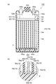
- the plurality of tubes 10a are arranged side by side with each other to form a group of active material holding tubes.
- Each tube 10a extends in the height direction (vertical direction) of the electric tank 120.
- the core metal 10b extends in the axial direction of the tube 10a at the center of the tube 10a.
- the positive electrode material 10c is filled between the tube 10a and the core metal 10b.
- the positive electrode and the negative electrode are in contact with the electrolytic solution in a state where the content X of the dialkylsulfosuccinic acid in the electrolytic solution is 0.1% by mass or less.
- the lead-acid battery according to the present embodiment can be obtained.
- the positive electrode tube and the negative electrode material of the negative electrode are in contact with the electrolytic solution.
- the amount of the surfactant used is such that the tube is easily impregnated with the surfactant so that a tube having excellent compressive strength can be easily obtained, the resin material is easily attached, and the electrolytic solution easily permeates during chemical conversion.
- 0 parts by mass or more is preferable, more than 0 parts by mass is more preferable, 0.1 parts by mass or more is further preferable, 0.2 parts by mass or more is particularly preferable, and 0.3 parts by mass or more is extremely preferable.
- 0.5 parts by mass or more is very preferable, 0.8 parts by mass or more is further preferable, and 1 part by mass or more is further preferable.
- a positive electrode having a core metal inserted in the tube and a positive electrode material filled between the tube and the core metal is obtained.
- a raw material for a positive electrode active material is filled between the core metal and the tube, and the lower end of the tube is closed with a lower joint to form an unchemical positive electrode.
- a positive electrode having a material can be obtained.
- the upper end of the tube may be closed with an upper joint.
- a negative electrode material paste containing a raw material for a negative electrode active material is filled in a negative electrode current collector (for example, a current collector lattice (cast lattice body, expanded lattice body, etc.)), and then aged and dried.
- a negative electrode current collector for example, a current collector lattice (cast lattice body, expanded lattice body, etc.)
- a negative electrode having a non-chemical negative electrode material can be obtained.
- the aging conditions are preferably 15 to 60 hours in an atmosphere with a temperature of 35 to 85 ° C. and a humidity of 50 to 98 RH%.
- the drying conditions are preferably 15 to 30 hours at a temperature of 45 to 80 ° C.
- Examples of the power supply device include UPS, disaster prevention (emergency) wireless power supply, telephone power supply, and the like.
- a lead storage battery for an electric vehicle is provided, and for example, a lead storage battery for a forklift is provided.
- a lead storage battery for a power supply device is provided.
- the upper joint was attached to the tubes. Then, a lead-antimony (4.0% by mass) -arsenic (0.2% by mass) -tin (0.015% by mass) alloy core metal (diameter 2.7 mm ⁇ x length 342 mm columnar) is formed. It was inserted into a tube, and lead powder containing lead monoxide as a main component was filled in the tube. Then, a lower joint was driven into the lower end of the tube to seal it, thereby obtaining a non-chemical positive electrode plate having 15 tubes.
- Example 1 A lead-acid battery was produced in the same manner as in Example 1 except that the amount of the surfactant A used was changed to 5.9 parts by mass with respect to 100 parts by mass of the solvent.
Landscapes
- Chemical & Material Sciences (AREA)
- Chemical Kinetics & Catalysis (AREA)
- Electrochemistry (AREA)
- General Chemical & Material Sciences (AREA)
- Engineering & Computer Science (AREA)
- Manufacturing & Machinery (AREA)
- Battery Electrode And Active Subsutance (AREA)
- Secondary Cells (AREA)
Abstract
Description
(GPC条件)
装置:高速液体クロマトグラフ LC-2200 Plus(日本分光株式会社製)
ポンプ:PU-2080
示差屈折率計:RI-2031
検出器:紫外可視吸光光度計UV-2075(λ:254nm)
カラムオーブン:CO-2065
カラム:TSKgel SuperAW(4000)、TSKgel SuperAW(3000)、TSKgel SuperAW(2500)(東ソー株式会社製)
カラム温度:40℃
溶離液:LiBr(10mM)及びトリエチルアミン(200mM)を含有するメタノール溶液
流速:0.6mL/分
分子量標準試料:ポリエチレングリコール(分子量:1.10×10⁶、5.80×10⁵、2.55×10⁵、1.46×10⁵、1.01×10⁵、4.49×10⁴、2.70×10⁴、2.10×10⁴;東ソー株式会社製)、ジエチレングリコール(分子量:1.06×10²;キシダ化学株式会社製)、ジブチルヒドロキシトルエン(分子量:2.20×10²;キシダ化学株式会社製)
本実施形態(後述の第1実施形態及び第2実施形態を含む。以下同様)に係る鉛蓄電池は、正極、負極及び電解液を備え、正極が活物質保持用のチューブを有し、負極が、界面活性剤を含有する負極材を有する。第1実施形態に係る鉛蓄電池では、電解液における負極材の界面活性剤とは異なる界面活性剤の合計の含有量Xが0.1質量%以下である。第2実施形態に係る鉛蓄電池では、負極が、ジアルキルスルホコハク酸とは異なる界面活性剤を含有する負極材を有し、電解液におけるジアルキルスルホコハク酸の含有量Xが0.1質量%以下である。本実施形態に係る鉛蓄電池によれば、優れた放電性能を得ることができる。
本実施形態に係る鉛蓄電池の製造方法は、正極、負極及び電解液を備える鉛蓄電池の製造方法であり、正極及び負極の化成処理を行う化成処理工程を備える。第1実施形態では、化成処理工程の後において、電解液における負極材の界面活性剤とは異なる界面活性剤の合計の含有量Xが0.1質量%以下である状態で正極及び負極が電解液に接触している。第2実施形態では、化成処理工程の後において、電解液におけるジアルキルスルホコハク酸の含有量Xが0.1質量%以下である状態で正極及び負極が電解液に接触している。本実施形態に係る鉛蓄電池の製造方法によれば、本実施形態に係る鉛蓄電池を得ることができる。本実施形態では、化成処理工程の後において、正極のチューブ及び負極の負極材が電解液に接触している。
本実施形態に係る電気車又は電源装置は、本実施形態に係る鉛蓄電池を備える。本実施形態に係る電気車又は電源装置の製造方法は、本実施形態に係る鉛蓄電池の製造方法により鉛蓄電池を得る工程を備える。本実施形態に係る電気車又は電源装置の製造方法は、例えば、本実施形態に係る鉛蓄電池の製造方法により鉛蓄電池を得る工程と、前記鉛蓄電池を含む構成部材を組み立てて電気車又は電源装置を得る工程とを備えている。電気車としては、フォークリフト、ゴルフカート等が挙げられる。電源装置としては、UPS、防災(非常)無線用電源、電話用電源等が挙げられる。本実施形態によれば、電気車用の鉛蓄電池が提供され、例えば、フォークリフト用の鉛蓄電池が提供される。本実施形態によれば、電源装置用の鉛蓄電池が提供される。
(実施例1)
アルカリガラス繊維を束ねたガラス糸を織り密度25目/25mmで編組した。編組後の管状の生スリーブでは、縦糸が24本であり、綾糸が48本であり、内径が9mmであった。次に、水(溶媒)100質量部と、フェノール樹脂(DIC株式会社製、商品名:フェノライトIG-1002)17質量部と、界面活性剤A(第一工業製薬株式会社製、商品名:ネオコールSW-C、ジ(2-エチルヘキシル)スルホコハク酸ナトリウム(別名:ジオクチルスルホコハク酸ナトリウム))1質量部と、を混合して混合溶液を得た。続いて、混合溶液に生スリーブを含浸させた(混合溶液:生スリーブ=1:0.032(質量比))。その後、生スリーブを内部温度250℃の通過型加熱炉に120秒間かけて通過させ、水分を蒸発させると共に樹脂成分を硬化させることによりガラス製のチューブを得た。
(熟成条件)温度:40℃、湿度:98RH%、時間:40時間
(乾燥条件)温度:60℃、時間:24時間
界面活性剤Aの使用量を溶媒100質量部に対して1.5質量部へ変更すると共に、電槽化成を行った後に電池内の電解液をすべて排出し、新たに希硫酸(比重:1.280)を液口部から注液したことを除き実施例1と同様にして鉛蓄電池を作製した。
界面活性剤Aの使用量を溶媒100質量部に対して1.5質量部へ変更したことを除き実施例1と同様にして鉛蓄電池を作製した。
界面活性剤Aの使用量を溶媒100質量部に対して5.9質量部へ変更したことを除き実施例2と同様にして鉛蓄電池を作製した。
界面活性剤Aの使用量を溶媒100質量部に対して5.9質量部へ変更したことを除き実施例1と同様にして鉛蓄電池を作製した。
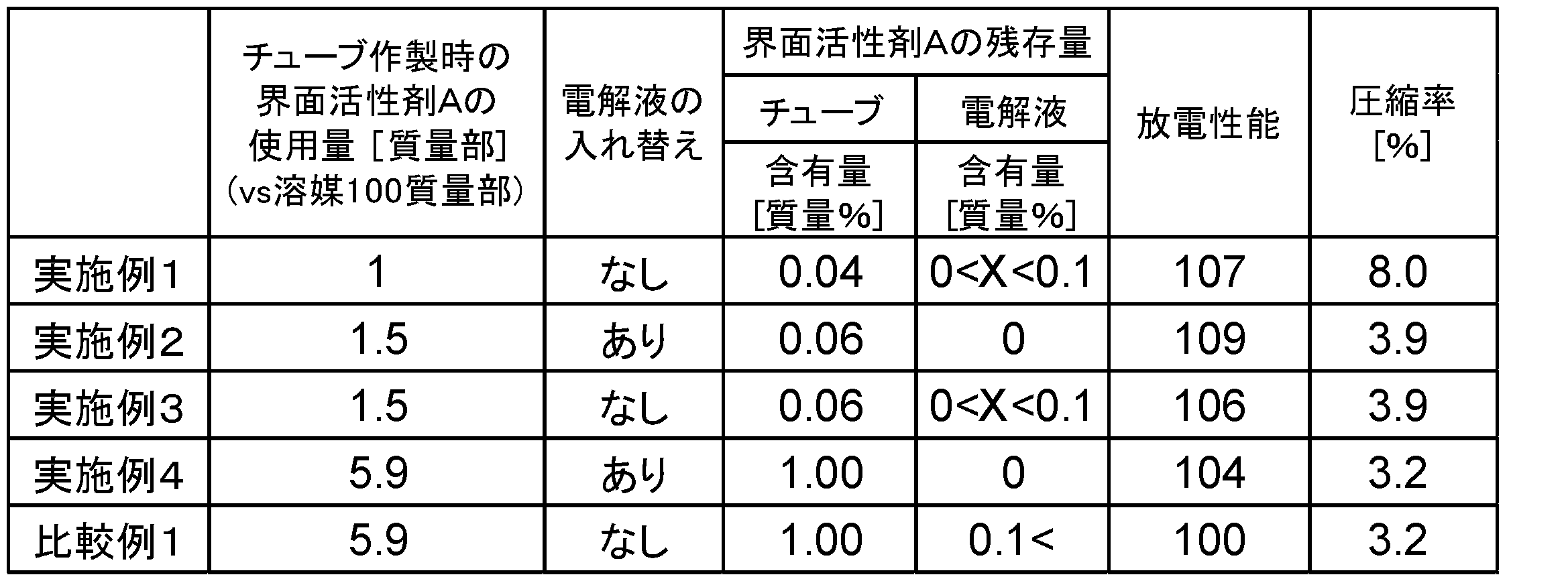
鉛蓄電池を解体して電解液及び活物質保持用のチューブを取り出し、高速液体クロマトグラフ(HPLC)により、チューブ及び電解液中の界面活性剤Aの含有量を測定した。測定結果を表1に示す。
定格容量確認試験を0.2CAにて行った。すなわち、雰囲気温度30℃中で、放電容量に対して120%を0.1CAの電流値で定電流充電して満充電状態に調整した。次に、満充電後の鉛蓄電池を水槽(温度:30℃)中に24時間放置した後、0.2CAで終止電圧1.7Vまで放電し、このときの放電容量(5時間率容量、0.2CA放電容量、定格容量。単位:Ah)を測定した。比較例1の放電容量の値を100として、放電容量を相対比較した。結果を表1に示す。
下記の手順で測定される圧縮率に基づきチューブの圧縮強度を評価した。株式会社安田精機製のYSS式ショッパー型厚さ測定器を用いて、上述の手順で作製されたガラス製のチューブの中央部の外径(t0)を0.01mm単位で測定した。次に、面積4cm2の加圧板(円板)を試料に当てた。そして、チューブの長手方向に対して垂直な方向から9.8Nの荷重をチューブに1分間加え、この時の中央部の外径(t1)を測定した。下記式より圧縮率[%]を測定した。結果を表1に示す。
圧縮率=(t0-t1)/t0×100
Claims (18)
- 正極、負極及び電解液を備え、
前記正極が活物質保持用のチューブを有し、
前記負極が、界面活性剤を含有する負極材を有し、
前記電解液における前記負極材の前記界面活性剤とは異なる界面活性剤の合計の含有量Xが0.1質量%以下である、鉛蓄電池。 - 前記チューブが、前記負極材の前記界面活性剤とは異なる界面活性剤を含有する、請求項1に記載の鉛蓄電池。
- 正極、負極及び電解液を備え、
前記正極が活物質保持用のチューブを有し、
前記負極が、ジアルキルスルホコハク酸とは異なる界面活性剤を含有する負極材を有し、
前記電解液におけるジアルキルスルホコハク酸の含有量Xが0.1質量%以下である、鉛蓄電池。 - 前記チューブがジアルキルスルホコハク酸を含有する、請求項3に記載の鉛蓄電池。
- 前記含有量Xが0質量%を超え0.1質量%以下である、請求項1~4のいずれか一項に記載の鉛蓄電池。
- 前記含有量Xが0質量%である、請求項1~4のいずれか一項に記載の鉛蓄電池。
- 前記負極材の前記界面活性剤がリグニンスルホン酸塩を含む、請求項1~6のいずれか一項に記載の鉛蓄電池。
- 前記チューブがガラスを含有する、請求項1~7のいずれか一項に記載の鉛蓄電池。
- 正極、負極及び電解液を備える鉛蓄電池の製造方法であって、
前記正極及び前記負極の化成処理を行う化成処理工程を備え、
前記正極が活物質保持用のチューブを有し、
前記負極が、界面活性剤を含有する負極材を有し、
前記化成処理工程の後において、前記電解液における前記負極材の前記界面活性剤とは異なる界面活性剤の合計の含有量Xが0.1質量%以下である状態で前記正極及び前記負極が前記電解液に接触している、鉛蓄電池の製造方法。 - 前記化成処理工程の後において、前記チューブが、前記負極材の前記界面活性剤とは異なる界面活性剤を含有する、請求項9に記載の鉛蓄電池の製造方法。
- 正極、負極及び電解液を備える鉛蓄電池の製造方法であって、
前記正極及び前記負極の化成処理を行う化成処理工程を備え、
前記正極が活物質保持用のチューブを有し、
前記負極が、ジアルキルスルホコハク酸とは異なる界面活性剤を含有する負極材を有し、
前記化成処理工程の後において、前記電解液におけるジアルキルスルホコハク酸の含有量Xが0.1質量%以下である状態で前記正極及び前記負極が前記電解液に接触している、鉛蓄電池の製造方法。 - 前記化成処理工程の後において、前記チューブがジアルキルスルホコハク酸を含有する、請求項11に記載の鉛蓄電池の製造方法。
- 前記含有量Xが0質量%を超え0.1質量%以下である、請求項9~12のいずれか一項に記載の鉛蓄電池の製造方法。
- 前記含有量Xが0質量%である、請求項9~12のいずれか一項に記載の鉛蓄電池の製造方法。
- 前記化成処理工程の前に、前記チューブを水洗する工程を更に備える、請求項9~14のいずれか一項に記載の鉛蓄電池の製造方法。
- 前記化成処理工程の後に、前記化成処理工程で用いた第1の電解液を除去すると共に、第2の電解液を前記正極及び前記負極に接触させる工程を更に備える、請求項9~15のいずれか一項に記載の鉛蓄電池の製造方法。
- 前記負極材の前記界面活性剤がリグニンスルホン酸塩を含む、請求項9~16のいずれか一項に記載の鉛蓄電池の製造方法。
- 前記チューブがガラスを含有する、請求項9~17のいずれか一項に記載の鉛蓄電池の製造方法。
Priority Applications (2)
| Application Number | Priority Date | Filing Date | Title |
|---|---|---|---|
| CN202080025405.4A CN113646925A (zh) | 2019-03-29 | 2020-02-19 | 铅蓄电池及其制造方法 |
| JP2020547243A JP6947311B2 (ja) | 2019-03-29 | 2020-02-19 | 鉛蓄電池の製造方法 |
Applications Claiming Priority (2)
| Application Number | Priority Date | Filing Date | Title |
|---|---|---|---|
| JP2019066365 | 2019-03-29 | ||
| JP2019-066365 | 2019-03-29 |
Publications (1)
| Publication Number | Publication Date |
|---|---|
| WO2020202869A1 true WO2020202869A1 (ja) | 2020-10-08 |
Family
ID=72667800
Family Applications (1)
| Application Number | Title | Priority Date | Filing Date |
|---|---|---|---|
| PCT/JP2020/006607 Ceased WO2020202869A1 (ja) | 2019-03-29 | 2020-02-19 | 鉛蓄電池及びその製造方法 |
Country Status (3)
| Country | Link |
|---|---|
| JP (1) | JP6947311B2 (ja) |
| CN (1) | CN113646925A (ja) |
| WO (1) | WO2020202869A1 (ja) |
Families Citing this family (1)
| Publication number | Priority date | Publication date | Assignee | Title |
|---|---|---|---|---|
| WO2021059533A1 (ja) * | 2019-09-27 | 2021-04-01 | 昭和電工マテリアルズ株式会社 | 活物質保持部材、電極及び鉛蓄電池 |
Citations (7)
| Publication number | Priority date | Publication date | Assignee | Title |
|---|---|---|---|---|
| JPS4529538B1 (ja) * | 1966-12-06 | 1970-09-26 | ||
| JPS485177B1 (ja) * | 1969-06-11 | 1973-02-14 | ||
| JPS5339439A (en) * | 1976-09-24 | 1978-04-11 | Yuasa Battery Co Ltd | Method of recovering lead battery |
| JPH0992268A (ja) * | 1995-09-25 | 1997-04-04 | Shin Kobe Electric Mach Co Ltd | クラッド式鉛蓄電池及びクラッド式鉛蓄電池用クラッドチューブの製造方法 |
| JP2000030756A (ja) * | 1998-07-10 | 2000-01-28 | Aiwa Co Ltd | 充電装置 |
| JP2005243585A (ja) * | 2004-02-27 | 2005-09-08 | Nippon Sheet Glass Co Ltd | 鉛蓄電池用セパレータ |
| WO2019004301A1 (ja) * | 2017-06-29 | 2019-01-03 | 日立化成株式会社 | 活物質保持用チューブ、電極及び鉛蓄電池 |
Family Cites Families (1)
| Publication number | Priority date | Publication date | Assignee | Title |
|---|---|---|---|---|
| JP2006073445A (ja) * | 2004-09-06 | 2006-03-16 | Furukawa Battery Co Ltd:The | ダンプ液の処理法 |
-
2020
- 2020-02-19 JP JP2020547243A patent/JP6947311B2/ja active Active
- 2020-02-19 WO PCT/JP2020/006607 patent/WO2020202869A1/ja not_active Ceased
- 2020-02-19 CN CN202080025405.4A patent/CN113646925A/zh active Pending
Patent Citations (7)
| Publication number | Priority date | Publication date | Assignee | Title |
|---|---|---|---|---|
| JPS4529538B1 (ja) * | 1966-12-06 | 1970-09-26 | ||
| JPS485177B1 (ja) * | 1969-06-11 | 1973-02-14 | ||
| JPS5339439A (en) * | 1976-09-24 | 1978-04-11 | Yuasa Battery Co Ltd | Method of recovering lead battery |
| JPH0992268A (ja) * | 1995-09-25 | 1997-04-04 | Shin Kobe Electric Mach Co Ltd | クラッド式鉛蓄電池及びクラッド式鉛蓄電池用クラッドチューブの製造方法 |
| JP2000030756A (ja) * | 1998-07-10 | 2000-01-28 | Aiwa Co Ltd | 充電装置 |
| JP2005243585A (ja) * | 2004-02-27 | 2005-09-08 | Nippon Sheet Glass Co Ltd | 鉛蓄電池用セパレータ |
| WO2019004301A1 (ja) * | 2017-06-29 | 2019-01-03 | 日立化成株式会社 | 活物質保持用チューブ、電極及び鉛蓄電池 |
Also Published As
| Publication number | Publication date |
|---|---|
| JPWO2020202869A1 (ja) | 2021-04-30 |
| JP6947311B2 (ja) | 2021-10-13 |
| CN113646925A (zh) | 2021-11-12 |
Similar Documents
| Publication | Publication Date | Title |
|---|---|---|
| KR102898379B1 (ko) | 개선된 납 축전지 분리기, 전극, 배터리 그리고 그 제조 방법 및 그 용도 | |
| CN114830384B (zh) | 活性物质保持部件、电极及铅蓄电池 | |
| JP2022017485A (ja) | 改善された電池セパレータ、電池、および関連方法 | |
| EP3648209A1 (en) | Active material holding tube, electrode, and lead storage battery | |
| KR20160082086A (ko) | 도전 보액 구조체 ⅱ | |
| JP6947311B2 (ja) | 鉛蓄電池の製造方法 | |
| US20170222279A1 (en) | Separator comprising force-locked particles | |
| KR102201100B1 (ko) | 클래드 튜브, 클래드식 전극, 납 축전지 및 이들의 제조 방법, 그리고 전동차 | |
| WO2019021690A1 (ja) | 鉛蓄電池 | |
| JP6915752B2 (ja) | 活物質保持部材及びその製造方法、電極、鉛蓄電池、並びに、電動車 | |
| JP7037858B2 (ja) | 活物質保持用チューブ、電極及び鉛蓄電池 | |
| JP7611828B2 (ja) | 樹脂部材、活物質保持部材、電極、鉛蓄電池及び電動車 | |
| JP7594537B2 (ja) | 活物質保持部材、電極、鉛蓄電池及び電動車 | |
| EP3734715A1 (en) | Active material holding tube, active material holding tube group, electrode, and lead storage battery | |
| WO2019220570A1 (ja) | 活物質保持部材、電極及び鉛蓄電池 | |
| WO2021166573A1 (ja) | 活物質保持部材及びその製造方法、電極、鉛蓄電池、マイクロハイブリッド車、並びに、電動車 | |
| KR20230044876A (ko) | 탄소 종이를 사용한 납축전지의 극판 제조방법 |
Legal Events
| Date | Code | Title | Description |
|---|---|---|---|
| ENP | Entry into the national phase |
Ref document number: 2020547243 Country of ref document: JP Kind code of ref document: A |
|
| 121 | Ep: the epo has been informed by wipo that ep was designated in this application |
Ref document number: 20784633 Country of ref document: EP Kind code of ref document: A1 |
|
| NENP | Non-entry into the national phase |
Ref country code: DE |
|
| 32PN | Ep: public notification in the ep bulletin as address of the adressee cannot be established |
Free format text: NOTING OF LOSS OF RIGHTS PURSUANT TO RULE 112(1) EPC (EPO FORM 1205A DATED 03/01/2022) |
|
| 122 | Ep: pct application non-entry in european phase |
Ref document number: 20784633 Country of ref document: EP Kind code of ref document: A1 |