WO2020202489A1 - ロータ、モータ、電動送風機、電気掃除機、及び手乾燥装置 - Google Patents
ロータ、モータ、電動送風機、電気掃除機、及び手乾燥装置 Download PDFInfo
- Publication number
- WO2020202489A1 WO2020202489A1 PCT/JP2019/014738 JP2019014738W WO2020202489A1 WO 2020202489 A1 WO2020202489 A1 WO 2020202489A1 JP 2019014738 W JP2019014738 W JP 2019014738W WO 2020202489 A1 WO2020202489 A1 WO 2020202489A1
- Authority
- WO
- WIPO (PCT)
- Prior art keywords
- rotor
- core
- permanent magnet
- motor
- electric blower
- Prior art date
- Legal status (The legal status is an assumption and is not a legal conclusion. Google has not performed a legal analysis and makes no representation as to the accuracy of the status listed.)
- Ceased
Links
Images






Classifications
-
- H—ELECTRICITY
- H02—GENERATION; CONVERSION OR DISTRIBUTION OF ELECTRIC POWER
- H02K—DYNAMO-ELECTRIC MACHINES
- H02K1/00—Details of the magnetic circuit
- H02K1/06—Details of the magnetic circuit characterised by the shape, form or construction
- H02K1/22—Rotating parts of the magnetic circuit
- H02K1/27—Rotor cores with permanent magnets
Definitions
- the present invention relates to a rotor used in a motor.
- An object of the present invention is to suppress a decrease in magnetic force in a small motor and to maintain the structural strength of the rotor even when the rotor rotates at high speed in the small motor.
- the rotor according to one aspect of the present invention A rotor core having an inner core and at least one outer core located outside the inner core in the radial direction. With at least one permanent magnet arranged between the inner core and the outer core, A shaft that is a magnetic material fixed to the inner iron core, A cover member that covers the rotor core is provided. When the outer diameter of the rotor core is ⁇ 1 and the minimum distance from at least one permanent magnet to the shaft is t1. Satisfy ⁇ 1 / t1 ⁇ 7.
- the motor according to another aspect of the present invention With the stator It has the rotor arranged inside the stator.
- the electric blower according to another aspect of the present invention is Feathers and It has the motor that rotates the blades.
- the vacuum cleaner according to another aspect of the present invention Dust collector and It has the electric blower that generates suction force and sends dust to the dust collecting part.
- the hand drying device according to another aspect of the present invention A housing with an intake port and an air outlet, It has the electric blower which is fixed inside the housing, sucks the air outside the housing through the intake port, and sends the air to the outside of the housing through the air outlet.
- the present invention it is possible to suppress a decrease in magnetic force in a small motor and maintain the structural strength of the rotor even when the rotor rotates at high speed in the small motor.
- FIG. 5 is a side view schematically showing an electric vacuum cleaner (also simply referred to as “vacuum cleaner”) according to the third embodiment of the present invention. It is a perspective view which shows typically the hand dryer as the hand drying apparatus which concerns on Embodiment 4 of this invention.
- Embodiment 1 In the xyz Cartesian coordinate system shown in each figure, the z-axis direction (z-axis) indicates a direction parallel to the axis Ax of the motor 1, and the x-axis direction (x-axis) is orthogonal to the z-axis direction (z-axis).
- the y-axis direction (y-axis) indicates a direction orthogonal to both the z-axis direction and the x-axis direction.
- the axis Ax is the center of rotation of the rotor 2.
- the direction parallel to the axis Ax is also referred to as "axial direction of rotor 2" or simply "axial direction”.
- the radial direction is the radial direction of the rotor 2 or the stator 3, and is the direction orthogonal to the axis Ax.
- the xy plane is a plane orthogonal to the axial direction.
- the arrow D1 indicates the circumferential direction centered on the axis Ax.
- the circumferential direction of the rotor 2 is also simply referred to as "circumferential direction”.
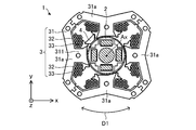
- FIG. 1 is a cross-sectional view schematically showing the structure of the motor 1 according to the first embodiment of the present invention.
- the motor 1 has a rotor 2, a stator 3, and a position sensor 4.
- the motor 1 is, for example, a permanent magnet synchronous motor (also referred to as a brushless DC motor) such as a permanent magnet embedded motor.
- Motor 1 is capable of high-speed rotation at 10,000 rpm or more.
- the motor 1 is, for example, a single-phase motor.
- the motor 1 may be a motor other than a single-phase motor, for example, a three-phase motor.
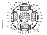
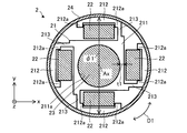
- FIG. 2 is a cross-sectional view schematically showing the structure of the rotor 2.
- the rotor 2 includes a rotor core 21, at least one permanent magnet 22, a shaft 23, and a cover member 24 (also simply referred to as a "cover").
- the rotor 2 is rotatably arranged inside the stator 3. There is an air gap between the rotor 2 and the stator 3.
- the rotor core 21 has an inner core 211 and at least one outer core 212.
- the rotor core 21 may further have at least one rib 213.
- the inner iron core 211 is, for example, a plurality of sheets laminated in the axial direction.
- the plurality of sheets are, for example, a plurality of electrical steel sheets.
- the inner iron core 211 has a shaft hole 211a.
- the inner core 211 may further have at least one inner protrusion 211b.
- the inner iron core 211 has a plurality of inner protrusions 211b, specifically, eight inner protrusions 211b.
- Each inner protrusion 211b supports the end of the permanent magnet 22 in the circumferential direction of the rotor 2.
- each medial projection 211b supports the longitudinal end of the permanent magnet 22.
- each permanent magnet 22 is positioned in the rotor core 21 and fixed in the rotor core 21.
- the outer iron core 212 is, for example, a plurality of sheets laminated in the axial direction.
- the plurality of sheets are, for example, a plurality of electrical steel sheets.
- the outer core 212 is located outside the inner core 211 in the radial direction of the rotor 2. That is, the inner core 211, one permanent magnet 22, and one outer core 212 are arranged in this order in the radial direction of the rotor 2.
- the rotor 2 has a plurality of ribs 213, specifically eight ribs 213.
- Each rib 213 is provided between the inner core 211 and the outer core 212.
- Each rib 213 connects the inner core 211 and the outer core 212.
- ribs 213 are provided on both sides of each outer core 212 in the circumferential direction.
- the rotor 2 has a plurality of permanent magnets 22 (specifically, four permanent magnets 22). Each permanent magnet 22 is arranged between the inner core 211 and the outer core 212. Each permanent magnet 22 forms one magnetic pole of the rotor 2. In this embodiment, the rotor 2 has four magnetic poles.
- Each permanent magnet 22 is, for example, a neodymium sintered magnet. As a result, the magnetic force of the permanent magnet 22 can be increased, and the output of the motor 1 can be increased. Each permanent magnet 22 is magnetized in the radial direction of the rotor 2.
- the permanent magnet 22 is a neodymium sintered magnet
- an eddy current loss may occur in the rotor 2 due to the demagnetic field from the stator 3, and the neodymium sintered magnet may generate heat.
- the neodymium sintered magnet is likely to be demagnetized. Therefore, it is desirable that the inner core 211 and each outer core 212 are a plurality of sheets laminated in the axial direction. Therefore, even if the permanent magnet 22 is a neodymium sintered magnet, the eddy current loss in the rotor 2 is reduced and neodymium Demagnetization of sintered magnets can be suppressed.
- the shaft 23 is a magnetic material.
- the shaft 23 is made of, for example, austenite such as SUS304.
- the shaft 23 is fixed to the inner iron core 211. Specifically, the shaft 23 is fixed to the shaft hole 211a. Therefore, the magnetic flux from each permanent magnet 22 passes through the shaft 23. Thereby, in the region between each permanent magnet 22 and the axis Ax, it is possible to secure a magnetic path for the magnetic flux to pass through. As a result, it is possible to suppress a decrease in the magnetic force of the rotor 2.
- the cover member 24 has, for example, a cylindrical shape.
- the cover member 24 covers the rotor core 21.
- the cover member 24 covers the outer peripheral surface of the rotor core 21.
- the stator 3 has a stator core 31, at least one insulator 32, and at least one winding 33.
- the stator 3 is arranged outside the rotor 2.
- the stator core 31 has four teeth 311.
- the stator core 31 is divided into a plurality of divided cores 31a. In the example shown in FIG. 1, the stator core 31 is divided into four divided cores 31a. Each split core 31a has one tooth 311.
- the insulator 32 insulates the stator core 31.
- Each insulator 32 is attached to a stator core 31.
- Each winding 33 is wound around an insulator 32.
- each winding 33 can be wound around the insulator 32 at a high density.
- the position sensor 4 has, for example, a Hall element that detects a magnetic field from the rotor 2. As a result, the position sensor 4 can detect the magnetic field from the rotor 2.
- the position sensor 4 is fixed by two insulators 32 adjacent to each other, for example, between the two teeth 311 of the stator core 31. As a result, the size of the motor 1 can be reduced.
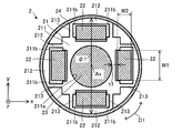
- FIG. 3 is a cross-sectional view schematically showing the structure of the rotor 2.
- the rotor 2 when the outer diameter of the rotor core 21 is ⁇ 1 and the minimum distance from at least one permanent magnet 22 to the shaft 23 is t1, the rotor 2 satisfies ⁇ 1 / t1 ⁇ 7.
- the minimum distance t1 is the distance from each permanent magnet 22 to the shaft 23 in the radial direction in the xy plane.
- the outer diameter ⁇ 1 [mm] of the rotor core 21 is, for example, 60 mm or less. However, when the ratio ⁇ 1 / t1 is 7 or more, the outer diameter ⁇ 1 [mm] of the rotor core 21 is 30 mm or less.
- each permanent magnet 22 has a rectangular shape.
- the width of each permanent magnet 22 in the longitudinal direction is indicated by W1
- the width of each permanent magnet 22 in the lateral direction is indicated by W2.
- the lateral direction is, for example, the same as the magnetization direction of the permanent magnet 22.
- the width W1 [mm] satisfies, for example, 2.4 ⁇ W1 ⁇ 38.4.
- the width W2 [mm] is, for example, 1.4 ⁇ W2 ⁇ 2.5.
- the ratio W1 / W2 of the width W1 and the width W2 is, for example, 1.7 ⁇ W1 / W2 ⁇ 15.4.
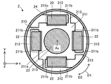
- FIG. 4 is a cross-sectional view showing another example of the rotor 2.
- the rib 213 is provided only on one side of each outer core 212 in the circumferential direction of the rotor 2.
- the leakage flux from one permanent magnet 22 to another adjacent permanent magnet 22 can be reduced.
- the magnetic force of the rotor 2 can be increased.
- the rotation direction D2 of the rotor 2 is clockwise.
- ribs 213 are provided on the downstream side of each outer core 212 in the rotation direction D2, and ribs 213 are provided on the upstream side of each outer core 212 in the rotation direction D2. Not done.
- FIG. 5 is a cross-sectional view showing still another example of the rotor 2.
- the rotor 2 shown in FIG. 5 does not have ribs 213. Therefore, the inner core 211 and each outer core 212 are not connected to each other. That is, each outer core 212 is separated from the inner core 211. As a result, the leakage flux from one permanent magnet 22 to another adjacent permanent magnet 22 can be reduced. As a result, the magnetic force of the rotor 2 can be increased.
- FIG. 6 is a cross-sectional view showing still another example of the rotor 2.
- each outer core 212 has at least one outer protrusion 212a.
- each outer core 212 has two outer protrusions 212a.
- Each outer protrusion 212a supports the end of the permanent magnet 22 in the circumferential direction of the rotor 2.
- each outer protrusion 212a supports the longitudinal end of the permanent magnet 22.
- each permanent magnet 22 is positioned in the rotor core 21 and fixed in the rotor core 21.
- the inner iron core 211 does not have the inner protrusion 211b, but may have one or more inner protrusions 211b.
- FIG. 7 is a cross-sectional view showing still another example of the rotor 2.
- the rotor 2 shown in FIG. 7 has at least one resin 26.
- the resin 26 is filled between the rotor core 21 and the cover member 24 in the interpole portion of the rotor 2.
- the interpole portion of the rotor 2 is a region between two permanent magnets 22 adjacent to each other in the circumferential direction of the rotor 2.
- the resin 26 transfers the heat of the rotor core 21, for example, the heat generated by each permanent magnet 22 to the cover member 24.
- the heat is released from the cover member 24 to the outside of the rotor 2. That is, the resin 26 promotes the release of heat from the rotor 2.
- the resin 26 suppresses the movement of each permanent magnet 22.
- the resin 26 can suppress the movement of each permanent magnet 22 in the circumferential direction due to the moment generated when the rotation of the rotor 2 starts or stops.
- a substance made of a material other than the resin may be filled between the rotor core 21 and the cover member 24.
- the substance made of a material other than the resin 26 is, for example, an insulating member that electrically insulates the rotor core 21 or a heat conductive member having high thermal conductivity.
- FIG. 8 is a cross-sectional view showing still another example of the rotor 2.
- the rotor 2 shown in FIG. 8 does not have an inner protrusion 211b and an outer protrusion 212a.
- the two ribs 213 support the ends of the permanent magnets 22 in the circumferential direction of the rotor 2.
- each rib 213 supports the longitudinal end of the permanent magnet 22.
- each permanent magnet 22 is positioned in the rotor core 21 and fixed in the rotor core 21.
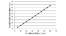
- FIG. 9 is a graph showing the relationship between the outer diameter ⁇ 1 of the rotor core 21 and the width W1 in the longitudinal direction of each permanent magnet 22.
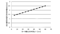
- FIG. 10 is a graph showing the relationship between the outer diameter ⁇ 1 of the rotor core 21 and the width W2 of each permanent magnet 22 in the lateral direction.
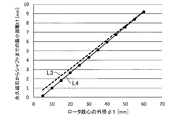
- FIG. 11 is a graph showing the relationship between the outer diameter ⁇ 1 of the rotor core 21 and the width ratio W1 / W2 of each permanent magnet 22.
- the broken line L1 shown in FIG. 11 shows the ratio W1 / W2 as a comparative example, and the line L2 shows the ratio W1 / W2 in the rotor 2 according to the present embodiment.
- each permanent magnet 22 is determined according to the outer diameter ⁇ 1 of the rotor core 21.
- the width W2 of each permanent magnet 22 in the lateral direction is determined according to the outer diameter ⁇ 1 of the rotor core 21.
- the dimensions of the permanent magnets of the rotor are determined according to the size of the rotor.
- the ratio of the width of each permanent magnet in the longitudinal direction to the width in the lateral direction is constant with respect to the size of the rotor (for example, the outer diameter of the rotor core) as shown by the broken line L1 in FIG. Is.
- the width ratio W1 / W2 of each permanent magnet 22 is not constant with respect to the outer diameter ⁇ 1 of the rotor core 21. That is, the smaller the outer diameter ⁇ 1 of the rotor core 21, the smaller the ratio W1 / W2. Specifically, the smaller the outer diameter ⁇ 1 of the rotor core 21, the greater the decrease in the ratio W1 / W2. More specifically, the smaller the outer diameter ⁇ 1 of the rotor core 21, the smaller the widths W1 and W2, but the reduction rate of the width W2 is smaller than the reduction rate of the width W1.
- the width W2 in the lateral direction is smaller than the width W1 in the longitudinal direction as the outer diameter ⁇ 1 of the rotor core becomes smaller than that of the rotor 2 according to the present embodiment.
- the permanent magnet is easily demagnetized by the demagnetizing field from the stator.
- a small motor for example, motor 1
- the ratio W1 / W2 satisfies W1 / W2 ⁇ 15.4.
- the ratio W1 / W2 satisfies W1 / W2 ⁇ 10.
- the width W1 is 18.4 mm or less
- the width W2 is 1.9 mm or less.
- FIG. 12 is a graph showing the relationship between the outer diameter ⁇ 1 of the rotor core 21 and the minimum distance t1 from each permanent magnet 22 to the shaft 23.
- the broken line L3 shown in FIG. 11 indicates the minimum distance t1 as a comparative example, and the line L4 indicates the minimum distance t1 in the rotor 2 of the motor 1 according to the present embodiment.
- the dimensions of the rotor core are determined according to the size of the rotor.
- the minimum distance from each permanent magnet to the shaft is constant with respect to the size of the rotor (for example, the outer diameter of the rotor core), as shown by the broken line L3 in FIG.
- the ratio of the minimum distance t1 from each permanent magnet 22 to the shaft 23 to the outer diameter ⁇ 1 of the rotor iron core 21 is not constant.
- the outer diameter ⁇ 1 of the rotor core 21 is The smaller the distance, the smaller the minimum distance t1. More specifically, the smaller the outer diameter ⁇ 1 of the rotor core 21, the larger the reduction rate of the minimum distance t1.
- FIG. 13 is a graph showing the relationship between the outer diameter ⁇ 1 of the rotor core 21, the outer diameter ⁇ 1 of the rotor core 21, and the ratio ⁇ 1 / t1 of the minimum distance t1 from each permanent magnet 22 to the shaft 23.
- FIG. 14 is a graph showing the relationship between the outer diameter ⁇ 1 of the rotor core 21, the ratio ⁇ 1 / t1 of the minimum distance t1 from each permanent magnet 22 to the shaft 23, and the magnetic force utilization rate of the rotor 2 in the motor 1.
- line L5 shows the magnetic force utilization of a rotor having a shaft made of a non-magnetic material as a comparative example
- line L6 has a shaft 23 made of a magnetic material according to the present embodiment. The magnetic force utilization rate of the rotor 2 according to the above is shown.
- the ratio ⁇ 1 / t1 sharply increases.
- the ratio ⁇ 1 / t1 is 7 or more (that is, ⁇ 1 ⁇ 30 mm)
- the magnetic force utilization rate of the rotor having a shaft made of a non-magnetic material drops sharply.
- the rotor 2 in the rotor 2 according to the present embodiment having the shaft 23 made of a magnetic material, the rotor has a ratio of ⁇ 1 / t1 of 7 or more.
- the decrease in the magnetic force utilization rate of 2 is suppressed.
- the shaft 23 since the shaft 23 is a magnetic material, the magnetic flux from each permanent magnet 22 passes through the shaft 23. Thereby, in the region between each permanent magnet 22 and the axis Ax, it is possible to secure a magnetic path for the magnetic flux to pass through. Therefore, in the present embodiment, even if the ratio ⁇ 1 / t1 is 7 or more, since the shaft 23 is a magnetic material, it is possible to suppress a decrease in the magnetic force of the rotor 2.
- each permanent magnet 22 is a neodymium sintered magnet
- the magnetic force of the rotor 2 increases as compared with, for example, a ferrite sintered magnet.
- the magnetic force of the rotor 2 increases, a large centrifugal force is generated in each permanent magnet 22, and the rotor core 21 is easily deformed.
- the rotor 2 shown in FIG. 2 is provided with ribs 213 on both sides of each permanent magnet 22, the structural strength of the rotor 2 is maintained even when the rotor 2 rotates at high speed in a small motor. can do.
- ribs 213 are provided only on one side of each outer core 212 in the circumferential direction of the rotor 2. As a result, the leakage flux from one permanent magnet 22 to another adjacent permanent magnet 22 can be reduced. As a result, it is possible to suppress a decrease in the magnetic force of the rotor 2.
- the rotor 2 shown in FIG. 5 does not have a rib 213. Thereby, the leakage flux from each permanent magnet 22 can be further reduced. As a result, the decrease in the magnetic force of the rotor 2 can be further suppressed.
- a centrifugal force in the radial direction is generated in each outer core 212. Even in this case, since each outer core 212 is covered with the cover member 24, the structural strength of the rotor 2 can be maintained. As a result, both maintenance and reliability of the magnetic force of the rotor 2 can be achieved.
- each outer core 212 of the rotor 2 may have at least one outer protrusion 212a.
- ribs 213 are provided only on one side of each outer iron core 212 in the circumferential direction of the rotor 2.
- the rotor 2 may have at least one resin 26.
- the resin 26 is filled between the rotor core 21 and the cover member 24 in the interpole portion of the rotor 2.
- the resin 26 transfers the heat of the rotor core 21, for example, the heat generated by each permanent magnet 22 to the cover member 24.
- the heat is released from the cover member 24 to the outside of the rotor 2. That is, the resin 26 promotes the release of heat from the rotor 2.
- the resin 26 suppresses the movement of each permanent magnet 22.
- the resin 26 can suppress the movement of each permanent magnet 22 in the circumferential direction due to the moment generated when the rotation of the rotor 2 starts or stops. As a result, the shape of the rotor 2 can be maintained, and the mechanical strength of the rotor 2 can be increased.
- the stator 3 When the outer diameter ⁇ 1 of the rotor core 21 is 30 mm or less, the stator 3 is downsized. With small motors, it is usually difficult to attach the windings to the stator at high density. Therefore, as shown in FIG. 1, when the stator core 31 is divided into a plurality of divided cores 31a, each winding 33 can be wound around the insulator 32 at a high density. As a result, the efficiency of the motor 1 can be increased.
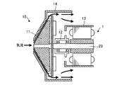
- FIG. 15 is a cross-sectional view schematically showing the structure of the electric blower 10 according to the second embodiment of the present invention.
- the electric blower 10 has a motor 1, a blade 11, a bearing 12, a motor frame 13, and a casing 14 according to the first embodiment.
- the blade 11 is fixed to the shaft 23 of the motor 1.
- the motor 1 and the bearing 12 are fixed to the motor frame 13.
- the bearing 12 rotatably supports the shaft 23 of the motor 1.
- the casing 14 covers the blades 11.
- the casing 14 may further cover the motor frame 13.
- the motor 1 rotates the blade 11.
- the blades 11 rotate and an air flow is generated.
- the electric blower 10 can blow air.
- the electric blower 10 according to the second embodiment has the advantages described in the first embodiment.
- the electric blower 10 according to the second embodiment has the motor 1 according to the first embodiment, the output of the electric blower 10 can be increased.
- the electric blower 10 according to the second embodiment has the motor 1 according to the first embodiment, the mechanical strength of the electric blower 10 can be increased.
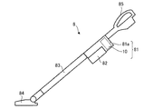
- FIG. 16 is a side view schematically showing the vacuum cleaner 8 (also simply referred to as “vacuum cleaner”) according to the third embodiment of the present invention.
- the vacuum cleaner 8 has a main body 81, a dust collector 82 (also referred to as a dust collector), a duct 83, a suction nozzle 84, and a grip portion 85.
- the main body 81 has an electric blower 10 according to the second embodiment and an exhaust port 81a.
- the electric blower 10 generates a suction force (specifically, an air flow) and sends dust to the dust collecting unit 82. Specifically, when the motor 1 in the electric blower 10 is driven, the blades 11 rotate to generate an air flow. Therefore, when the motor 1 in the electric blower 10 is driven, a suction force is generated, and dust is sent from the suction nozzle 84 to the dust collecting unit 82.
- a suction force specifically, an air flow
- the dust collecting unit 82 is attached to the main body 81.
- the dust collecting unit 82 may be provided inside the main body 81.
- the dust collecting unit 82 is a container having a filter for separating dust and air.
- the suction nozzle 84 is attached to the tip of the duct 83.
- the vacuum cleaner 8 according to the third embodiment has the electric blower 10 described in the second embodiment, it has the advantages described in the second embodiment.
- the vacuum cleaner 8 according to the third embodiment has the electric blower 10 described in the second embodiment, the power of the vacuum cleaner 8 can be increased.
- the vacuum cleaner 8 according to the third embodiment has the electric blower 10 described in the second embodiment, the mechanical strength of the vacuum cleaner 8 can be increased.
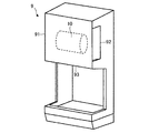
- FIG. 17 is a perspective view schematically showing a hand dryer 9 as a hand drying device according to a fourth embodiment of the present invention.
- the hand dryer 9 as a hand drying device has a housing 91 and an electric blower 10 according to the second embodiment.
- the housing 91 has at least one intake port 92 and at least one air outlet 93.
- the electric blower 10 is fixed inside the housing 91.
- the electric blower 10 When the electric blower 10 is driven, an air flow is generated. Specifically, the electric blower 10 sucks the air outside the housing 91 through the intake port 92, and sends the air to the outside of the housing 91 through the air blower port 93. As a result, the hand dryer 9 sucks air and blows it.
- the user of the hand dryer 9 can blow off the water droplets adhering to the hand and dry the hand by holding the hand near the air outlet 93.
- the hand dryer 9 according to the fourth embodiment has the electric blower 10 described in the second embodiment, it has the advantages described in the second embodiment.
- the hand dryer 9 according to the fourth embodiment has the electric blower 10 described in the second embodiment, the output of the hand dryer 9 can be increased.
- the hand dryer 9 according to the fourth embodiment has the electric blower 10 described in the second embodiment, the mechanical strength of the hand dryer 9 can be increased.
Landscapes
- Engineering & Computer Science (AREA)
- Power Engineering (AREA)
- Permanent Field Magnets Of Synchronous Machinery (AREA)
- Iron Core Of Rotating Electric Machines (AREA)
Abstract
ロータ(2)は、ロータ鉄心(21)と、少なくとも1つの永久磁石(22)と、シャフト(23)と、カバー部材(24)とを有する。ロータ鉄心(21)は、内側鉄心(211)と、少なくとも1つの外側鉄心(212)とを有する。シャフト(23)は、磁性体である。カバー部材(24)は、ロータ鉄心(21)を覆う。ロータ鉄心(21)の外径をφ1とし、少なくとも1つの永久磁石(22)からシャフト(23)までの最小距離をt1としたとき、ロータ(2)は、φ1/t1≧7を満たす。
Description
本発明は、モータに用いられるロータに関する。
一般に、1万rpm以上で高速回転する小型モータが用いられている。小型モータでは、通常、中型モータ又は大型モータに比べて出力が低下するので、小型モータにおける高出力化が求められている。小型モータの出力を高めるため、ロータにおける漏れ磁束を低減し、且つ有効磁束を増加させるための構造が提案されている(例えば、特許文献1)。
しかしながら、通常、ロータ鉄心の外径が小さくなるほど、永久磁石の寸法が小さくなる。その結果、ステータからの反磁界により、永久磁石が減磁しやすい。そのため、小型モータにおいて出力を高めるための種々の構造が提案されているが、永久磁石を含むロータでは、ロータの回転が高速になるほどロータに生じる遠心力が増加し、ロータの構造的な強度を維持することが困難である。
本発明の目的は、小型モータにおける磁力の低下を抑制するとともに、ロータが小型モータにおいて高速回転する場合でも、ロータの構造的な強度を維持することである。
本発明の一態様に係るロータは、
内側鉄心と、径方向において前記内側鉄心の外側に位置する少なくとも1つの外側鉄心とを有するロータ鉄心と、
前記内側鉄心と前記外側鉄心との間に配置された少なくとも1つの永久磁石と、
前記内側鉄心に固定された、磁性体であるシャフトと、
前記ロータ鉄心を覆うカバー部材と
を備え、
前記ロータ鉄心の外径をφ1とし、前記少なくとも1つの永久磁石から前記シャフトまでの最小距離をt1としたとき、
φ1/t1≧7を満たす。
本発明の他の態様に係るモータは、
ステータと、
前記ステータの内側に配置された前記ロータと
を有する。
本発明の他の態様に係る電動送風機は、
羽根と、
前記羽根を回転させる前記モータと
を有する。
本発明の他の態様に係る電気掃除機は、
集塵部と、
吸引力を発生させ、前記集塵部に塵埃を送り込む前記電動送風機と
を有する。
本発明の他の態様に係る手乾燥装置は、
吸気口及び送風口を有する筐体と、
前記筐体の内部に固定されており、前記吸気口を通して前記筐体の外部の空気を吸引し、前記送風口を通して前記筐体の外部に前記空気を送る前記電動送風機と
を有する。
内側鉄心と、径方向において前記内側鉄心の外側に位置する少なくとも1つの外側鉄心とを有するロータ鉄心と、
前記内側鉄心と前記外側鉄心との間に配置された少なくとも1つの永久磁石と、
前記内側鉄心に固定された、磁性体であるシャフトと、
前記ロータ鉄心を覆うカバー部材と
を備え、
前記ロータ鉄心の外径をφ1とし、前記少なくとも1つの永久磁石から前記シャフトまでの最小距離をt1としたとき、
φ1/t1≧7を満たす。
本発明の他の態様に係るモータは、
ステータと、
前記ステータの内側に配置された前記ロータと
を有する。
本発明の他の態様に係る電動送風機は、
羽根と、
前記羽根を回転させる前記モータと
を有する。
本発明の他の態様に係る電気掃除機は、
集塵部と、
吸引力を発生させ、前記集塵部に塵埃を送り込む前記電動送風機と
を有する。
本発明の他の態様に係る手乾燥装置は、
吸気口及び送風口を有する筐体と、
前記筐体の内部に固定されており、前記吸気口を通して前記筐体の外部の空気を吸引し、前記送風口を通して前記筐体の外部に前記空気を送る前記電動送風機と
を有する。
本発明によれば、小型モータにおける磁力の低下を抑制するとともに、ロータが小型モータにおいて高速回転する場合でも、ロータの構造的な強度を維持することができる。
実施の形態1.
各図に示されるxyz直交座標系において、z軸方向(z軸)は、モータ1の軸線Axと平行な方向を示し、x軸方向(x軸)は、z軸方向(z軸)に直交する方向を示し、y軸方向(y軸)は、z軸方向及びx軸方向の両方に直交する方向を示す。軸線Axは、ロータ2の回転中心である。軸線Axと平行な方向は、「ロータ2の軸方向」又は単に「軸方向」ともいう。径方向は、ロータ2又はステータ3の半径方向であり、軸線Axと直交する方向である。xy平面は、軸方向と直交する平面である。矢印D1は、軸線Axを中心とする周方向を示す。ロータ2の周方向を、単に「周方向」ともいう。
各図に示されるxyz直交座標系において、z軸方向(z軸)は、モータ1の軸線Axと平行な方向を示し、x軸方向(x軸)は、z軸方向(z軸)に直交する方向を示し、y軸方向(y軸)は、z軸方向及びx軸方向の両方に直交する方向を示す。軸線Axは、ロータ2の回転中心である。軸線Axと平行な方向は、「ロータ2の軸方向」又は単に「軸方向」ともいう。径方向は、ロータ2又はステータ3の半径方向であり、軸線Axと直交する方向である。xy平面は、軸方向と直交する平面である。矢印D1は、軸線Axを中心とする周方向を示す。ロータ2の周方向を、単に「周方向」ともいう。
図1は、本発明の実施の形態1に係るモータ1の構造を概略的に示す断面図である。
モータ1は、ロータ2と、ステータ3と、位置センサ4とを有する。モータ1は、例えば、永久磁石埋込型電動機などの永久磁石同期電動機(ブラシレスDCモータともいう)である。
モータ1は、ロータ2と、ステータ3と、位置センサ4とを有する。モータ1は、例えば、永久磁石埋込型電動機などの永久磁石同期電動機(ブラシレスDCモータともいう)である。
モータ1は、1万rpm以上での高速回転が可能である。モータ1は、例えば、単相モータである。ただし、モータ1は、単相モータ以外のモータ、例えば、3相モータでもよい。
図2は、ロータ2の構造を概略的に示す断面図である。
ロータ2は、ロータ鉄心21と、少なくとも1つの永久磁石22と、シャフト23と、カバー部材24(単に「カバー」ともいう)とを有する。ロータ2は、ステータ3の内側に回転可能に配置されている。ロータ2とステータ3との間には、エアギャップが存在する。
ロータ2は、ロータ鉄心21と、少なくとも1つの永久磁石22と、シャフト23と、カバー部材24(単に「カバー」ともいう)とを有する。ロータ2は、ステータ3の内側に回転可能に配置されている。ロータ2とステータ3との間には、エアギャップが存在する。
ロータ鉄心21は、内側鉄心211と、少なくとも1つの外側鉄心212とを有する。ロータ鉄心21は、さらに、少なくとも1つのリブ213を有してもよい。
内側鉄心211は、例えば、軸方向に積層された複数のシートである。複数のシートは、例えば、複数の電磁鋼板である。内側鉄心211は、シャフト孔211aを有する。内側鉄心211は、さらに、少なくとも1つの内側突起211bを持っていてもよい。
図1及び図2に示される例では、内側鉄心211は、複数の内側突起211b、具体的には、8個の内側突起211bを持っている。各内側突起211bは、ロータ2の周方向における永久磁石22の端部を支持する。言い換えると、xy平面において、各内側突起211bは、永久磁石22の長手方向における端部を支持する。これにより、各永久磁石22は、ロータ鉄心21内で位置決めされており、ロータ鉄心21内で固定されている。
外側鉄心212は、例えば、軸方向に積層された複数のシートである。複数のシートは、例えば、複数の電磁鋼板である。外側鉄心212は、ロータ2の径方向において内側鉄心211の外側に位置する。すなわち、内側鉄心211、1つの永久磁石22、1つの外側鉄心212は、ロータ2の径方向において、この順に配列されている。
図1及び図2に示される例では、ロータ2は、複数のリブ213、具体的には、8個のリブ213を有する。各リブ213は、内側鉄心211と外側鉄心212との間に設けられている。各リブ213は、内側鉄心211及び外側鉄心212を連結する。図1及び図2に示される例では、周方向における各外側鉄心212の両側にリブ213が設けられている。
図2に示される例では、ロータ2は、複数の永久磁石22(具体的には、4つの永久磁石22)を有する。各永久磁石22は、内側鉄心211と外側鉄心212との間に配置されている。各永久磁石22は、ロータ2の1磁極を形成する。本実施の形態では、ロータ2は、4磁極を持つ。
各永久磁石22は、例えば、ネオジム焼結磁石である。これにより、永久磁石22の磁力を高めることができ、モータ1の出力を高めることができる。各永久磁石22は、ロータ2の径方向に磁化されている。
永久磁石22がネオジム焼結磁石であるとき、ステータ3からの反磁界によってロータ2に渦電流損が生じ、ネオジム焼結磁石が発熱する場合がある。この場合、ネオジム焼結磁石が減磁しやすい。そのため、内側鉄心211及び各外側鉄心212が軸方向に積層された複数のシートであることが望ましい、これにより、永久磁石22がネオジム焼結磁石でも、ロータ2における渦電流損が低減し、ネオジム焼結磁石の減磁を抑えることができる。
シャフト23は、磁性体である。シャフト23は、例えば、SUS304のようなオーステナイトで作られている。シャフト23は、内側鉄心211に固定されている。具体的には、シャフト23は、シャフト孔211aに固定されている。したがって、各永久磁石22からの磁束がシャフト23を通る。これにより、各永久磁石22と軸線Axとの間の領域において、磁束が通るための磁路を確保することができる。その結果、ロータ2の磁力の低下を抑制することができる。
カバー部材24は、例えば、円筒形状を持つ。カバー部材24は、ロータ鉄心21を覆っている。具体的には、カバー部材24は、ロータ鉄心21の外周面を覆っている。これにより、ロータ2の回転中に、ロータ2に大きな遠心力が生じた場合でも、外側鉄心212の飛散を防止することができる。言い換えると、モータ1は、カバー部材24を有するので、ロータ2が高速で回転することができる。
ステータ3は、ステータコア31と、少なくとも1つのインシュレータ32と、少なくとも1つの巻線33とを有する。ステータ3は、ロータ2の外側に配置されている。
ステータコア31は、4つのティース311を有する。
ステータコア31は、複数の分割コア31aに分割されている。図1に示される例では、ステータコア31は、4つの分割コア31aに分割されている。各分割コア31aは、1つのティース311を有する。
インシュレータ32は、ステータコア31を絶縁する。各インシュレータ32は、ステータコア31に取り付けられている。各巻線33は、インシュレータ32に巻かれている。
図1に示されるように、ステータコア31が複数の分割コア31aに分割されている場合、各巻線33を高密度でインシュレータ32に巻くことができる。
位置センサ4は、例えば、ロータ2からの磁界を検出するホール素子を有する。これにより、位置センサ4は、ロータ2からの磁界を検出することができる。位置センサ4は、例えば、ステータコア31の2つのティース311の間において、互いに隣接する2つのインシュレータ32で固定されている。これにより、モータ1のサイズを小型化することができる。
位置センサ4を用いてロータ2からの磁界を検出し、ロータ2の回転位置(具体的には、位相)を検出することにより、モータ1の制御が容易になる。
図3は、ロータ2の構造を概略的に示す断面図である。
図3に示されるように、ロータ鉄心21の外径をφ1とし、少なくとも1つの永久磁石22からシャフト23までの最小距離をt1としたとき、ロータ2は、φ1/t1≧7を満たす。図3に示される例では、最小距離t1は、xy平面において、径方向における各永久磁石22からシャフト23までの距離である。
図3に示されるように、ロータ鉄心21の外径をφ1とし、少なくとも1つの永久磁石22からシャフト23までの最小距離をt1としたとき、ロータ2は、φ1/t1≧7を満たす。図3に示される例では、最小距離t1は、xy平面において、径方向における各永久磁石22からシャフト23までの距離である。
ロータ鉄心21の外径φ1[mm]は、例えば、60mm以下である。ただし、比率φ1/t1が7以上であるとき、ロータ鉄心21の外径φ1[mm]は、30mm以下である。
図3に示されるxy平面において、各永久磁石22は、矩形形状を持つ。図3に示されるxy平面において、各永久磁石22の長手方向における幅はW1で示され、各永久磁石22の短手方向における幅はW2で示される。各永久磁石22において、短手方向は、例えば、永久磁石22の磁化方向と同じである。
幅W1[mm]は、例えば、2.4≦W1≦38.4を満たす。幅W2[mm]は、例えば、1.4≦W2≦2.5である。この場合、幅W1及び幅W2の比率W1/W2は、例えば、1.7≦W1/W2≦15.4である。これにより、各永久磁石22の減磁を抑制することができ、ロータ2を含むモータにおける出力を高めることができる。
〈変形例1〉
図4は、ロータ2の他の例を示す断面図である。
図4に示される例では、ロータ2の周方向における各外側鉄心212の片側のみにリブ213が設けられている。これにより、1つの永久磁石22から隣接する他の永久磁石22への漏れ磁束を低減することができる。その結果、ロータ2の磁力を高めることができる。
図4は、ロータ2の他の例を示す断面図である。
図4に示される例では、ロータ2の周方向における各外側鉄心212の片側のみにリブ213が設けられている。これにより、1つの永久磁石22から隣接する他の永久磁石22への漏れ磁束を低減することができる。その結果、ロータ2の磁力を高めることができる。
図4に示される例では、ロータ2の回転方向D2は時計回りである。この場合において、図4に示されるロータ2では、回転方向D2における各外側鉄心212の下流側にリブ213が設けられており、各外側鉄心212の回転方向D2における上流側にはリブ213が設けられていない。
〈変形例2〉
図5は、ロータ2のさらに他の例を示す断面図である。
図5に示されるロータ2は、リブ213を有していない。したがって、内側鉄心211及び各外側鉄心212は、互いに連結していない。すなわち、各外側鉄心212は、内側鉄心211から離間している。これにより、1つの永久磁石22から隣接する他の永久磁石22への漏れ磁束を低減することができる。その結果、ロータ2の磁力を高めることができる。
図5は、ロータ2のさらに他の例を示す断面図である。
図5に示されるロータ2は、リブ213を有していない。したがって、内側鉄心211及び各外側鉄心212は、互いに連結していない。すなわち、各外側鉄心212は、内側鉄心211から離間している。これにより、1つの永久磁石22から隣接する他の永久磁石22への漏れ磁束を低減することができる。その結果、ロータ2の磁力を高めることができる。
〈変形例3〉
図6は、ロータ2のさらに他の例を示す断面図である。
図6に示される例では、各外側鉄心212は、少なくとも1つの外側突起212aを持っている。具体的には、図6に示される例では、各外側鉄心212は、2つの外側突起212aを持っている。各外側突起212aは、ロータ2の周方向における永久磁石22の端部を支持する。言い換えると、xy平面において、各外側突起212aは、永久磁石22の長手方向における端部を支持する。これにより、各永久磁石22は、ロータ鉄心21内で位置決めされており、ロータ鉄心21内で固定されている。
図6は、ロータ2のさらに他の例を示す断面図である。
図6に示される例では、各外側鉄心212は、少なくとも1つの外側突起212aを持っている。具体的には、図6に示される例では、各外側鉄心212は、2つの外側突起212aを持っている。各外側突起212aは、ロータ2の周方向における永久磁石22の端部を支持する。言い換えると、xy平面において、各外側突起212aは、永久磁石22の長手方向における端部を支持する。これにより、各永久磁石22は、ロータ鉄心21内で位置決めされており、ロータ鉄心21内で固定されている。
図6に示される例では、内側鉄心211は、内側突起211bを有していないが、1以上の内側突起211bを有していてもよい。
〈変形例4〉
図7は、ロータ2のさらに他の例を示す断面図である。
図7に示されるロータ2は、少なくとも1つの樹脂26を有する。樹脂26は、ロータ2の極間部において、ロータ鉄心21とカバー部材24との間に充填されている。ロータ2の極間部は、ロータ2の周方向において隣接する2つの永久磁石22の間の領域である。樹脂26は、ロータ鉄心21の熱、例えば、各永久磁石22で生じた熱をカバー部材24へ伝達する。その熱は、カバー部材24からロータ2の外へ放出される。すなわち、樹脂26は、ロータ2の熱の放出を促進させる。
図7は、ロータ2のさらに他の例を示す断面図である。
図7に示されるロータ2は、少なくとも1つの樹脂26を有する。樹脂26は、ロータ2の極間部において、ロータ鉄心21とカバー部材24との間に充填されている。ロータ2の極間部は、ロータ2の周方向において隣接する2つの永久磁石22の間の領域である。樹脂26は、ロータ鉄心21の熱、例えば、各永久磁石22で生じた熱をカバー部材24へ伝達する。その熱は、カバー部材24からロータ2の外へ放出される。すなわち、樹脂26は、ロータ2の熱の放出を促進させる。
さらに、樹脂26は、各永久磁石22の移動を抑制する。例えば、樹脂26は、ロータ2の回転開始時又は停止時に生じるモーメントにより各永久磁石22が周方向に移動することを抑制することができる。
樹脂26の代わりに、樹脂以外の材料で作られた物質をロータ鉄心21とカバー部材24との間に充填してもよい。樹脂26以外の材料で作られた物質は、例えば、ロータ鉄心21を電気的に絶縁する絶縁部材、又は熱伝導性の高い熱伝導部材である。
〈変形例5〉
図8は、ロータ2のさらに他の例を示す断面図である。
図8に示されるロータ2は、内側突起211b及び外側突起212aを持っていない。図8に示される例では、2つのリブ213は、ロータ2の周方向における永久磁石22の端部を支持する。言い換えると、xy平面において、各リブ213は、永久磁石22の長手方向における端部を支持する。これにより、各永久磁石22は、ロータ鉄心21内で位置決めされており、ロータ鉄心21内で固定されている。
図8は、ロータ2のさらに他の例を示す断面図である。
図8に示されるロータ2は、内側突起211b及び外側突起212aを持っていない。図8に示される例では、2つのリブ213は、ロータ2の周方向における永久磁石22の端部を支持する。言い換えると、xy平面において、各リブ213は、永久磁石22の長手方向における端部を支持する。これにより、各永久磁石22は、ロータ鉄心21内で位置決めされており、ロータ鉄心21内で固定されている。
〈ロータ2の利点〉
ロータ2の利点について説明する。
図9は、ロータ鉄心21の外径φ1と各永久磁石22の長手方向における幅W1との関係を示すグラフである。
図10は、ロータ鉄心21の外径φ1と各永久磁石22の短手方向における幅W2との関係を示すグラフである。
図11は、ロータ鉄心21の外径φ1と各永久磁石22における幅の比率W1/W2との関係を示すグラフである。図11に示される破線L1は、比較例としての比率W1/W2を示し、線L2は、本実施の形態に係るロータ2における比率W1/W2を示す。
ロータ2の利点について説明する。
図9は、ロータ鉄心21の外径φ1と各永久磁石22の長手方向における幅W1との関係を示すグラフである。
図10は、ロータ鉄心21の外径φ1と各永久磁石22の短手方向における幅W2との関係を示すグラフである。
図11は、ロータ鉄心21の外径φ1と各永久磁石22における幅の比率W1/W2との関係を示すグラフである。図11に示される破線L1は、比較例としての比率W1/W2を示し、線L2は、本実施の形態に係るロータ2における比率W1/W2を示す。
図9に示されるように、各永久磁石22の長手方向における幅W1は、ロータ鉄心21の外径φ1に応じて定められる。同様に、図10に示されるように、各永久磁石22の短手方向における幅W2は、ロータ鉄心21の外径φ1に応じて定められる。
通常、ロータの永久磁石の寸法は、ロータの大きさに応じて定められる。この場合、各永久磁石の長手方向における幅と短手方向における幅との比率は、図11において破線L1で示されるように、ロータの大きさ(例えば、ロータ鉄心の外径)に対して一定である。
これに対して、図11において線L2で示されるように、本実施の形態では、各永久磁石22における幅の比率W1/W2は、ロータ鉄心21の外径φ1に対して一定ではない。すなわち、ロータ鉄心21の外径φ1が小さくなるほど、比率W1/W2が小さくなる。具体的には、ロータ鉄心21の外径φ1が小さくなるほど、比率W1/W2の減少が大きくなる。より具体的には、ロータ鉄心21の外径φ1が小さくなるほど幅W1及びW2が小さくなるが、幅W1の減少率に比べて幅W2の減少率は小さい。言い換えると、ロータ鉄心21の外径φ1が小さくなるほど幅W1及びW2が小さくなるが、外径φ1の減少に対する幅W1の減少に比べて外径φ1の減少に対する幅W2の減少は小さい。
図11において破線L1で示される特性を持つロータでは、本実施の形態に係るロータ2に比べて、ロータ鉄心の外径φ1が小さくなるほど、長手方向における幅W1に対する短手方向における幅W2が小さくなる。その結果、破線L1で示される特性を持つロータでは、ステータからの反磁界により、永久磁石が減磁しやすい。
これに対して、本実施の形態に係るロータ2では、上述のように、ロータ鉄心21の外径φ1が小さくなるほど、比率W1/W2が小さくなる。具体的には、ロータ鉄心21の外径φ1が小さくなるほど幅W1及びW2が小さくなるが、外径φ1の減少に対する幅W1の減少に比べて外径φ1の減少に対する幅W2の減少は小さい。これにより、ロータ鉄心21の外径φ1を小型化した場合でも、各永久磁石22の磁力の低下を抑制することができる。
したがって、小型モータ(例えば、モータ1)において、ロータ鉄心21の外径φ1が60mm以下である場合、比率W1/W2が、W1/W2≦15.4を満たすことが望ましい。特に、φ1≦30mmのとき、比率W1/W2が、W1/W2<10を満たすことが望ましい。φ1≦30mmのとき、幅W1は、18.4mm以下であり、幅W2は、1.9mm以下である。これにより、ロータ2の磁力の低下を抑制することができ、ロータ2を含むモータにおける出力を高めることができる。
図12は、ロータ鉄心21の外径φ1と各永久磁石22からシャフト23までの最小距離t1との関係を示すグラフである。図11に示される破線L3は、比較例としての最小距離t1を示し、線L4は、本実施の形態に係るモータ1のロータ2における最小距離t1を示す。
通常、ロータ鉄心の寸法は、ロータの大きさに応じて定められる。この場合、各永久磁石からシャフトまでの最小距離は、図12において破線L3で示されるように、ロータの大きさ(例えば、ロータ鉄心の外径)に対して一定である。これに対して、本実施の形態では、図12において線L4で示されるように、ロータ鉄心21の外径φ1に対する各永久磁石22からシャフト23までの最小距離t1の比率は一定ではない。具体的には、シャフト孔211aの直径が同じであり、外径φ1の減少に対する幅W1の減少に比べて外径φ1の減少に対する幅W2の減少が小さいため、ロータ鉄心21の外径φ1が小さくなるほど最小距離t1が小さくなる。より具体的には、ロータ鉄心21の外径φ1が小さくなるほど、最小距離t1の減少率が大きくなる。
図13は、ロータ鉄心21の外径φ1とロータ鉄心21の外径φ1及び各永久磁石22からシャフト23までの最小距離t1の比率φ1/t1との関係を示すグラフである。
図14は、ロータ鉄心21の外径φ1及び各永久磁石22からシャフト23までの最小距離t1の比率φ1/t1とモータ1におけるロータ2の磁力利用率との関係を示すグラフである。図14において、線L5は、非磁性体で作られたシャフトを持つロータの磁力利用率を比較例として示しており、線L6は、磁性体で作られたシャフト23を持つ、本実施の形態に係るロータ2の磁力利用率を示している。
図14は、ロータ鉄心21の外径φ1及び各永久磁石22からシャフト23までの最小距離t1の比率φ1/t1とモータ1におけるロータ2の磁力利用率との関係を示すグラフである。図14において、線L5は、非磁性体で作られたシャフトを持つロータの磁力利用率を比較例として示しており、線L6は、磁性体で作られたシャフト23を持つ、本実施の形態に係るロータ2の磁力利用率を示している。
図13に示されるように、ロータ鉄心21の外径φ1が小さくなるにつれて、比率φ1/t1が急激に上昇する。比率φ1/t1が7以上であるとき(すなわち、φ1≦30mm)、通常、ロータの径方向内側において、磁束が通るための磁路を確保することが難しい。この場合、図14において線L5で示されるように、非磁性体で作られたシャフトを持つロータの磁力利用率は急激に低下する。
これに対して、図14において線L6で示されるように、磁性体で作られたシャフト23を持つ、本実施の形態に係るロータ2では、比率φ1/t1が7以上であっても、ロータ2の磁力利用率の低下は抑えられている。本実施の形態では、シャフト23が磁性体であるので、各永久磁石22からの磁束がシャフト23を通る。これにより、各永久磁石22と軸線Axとの間の領域において、磁束が通るための磁路を確保することができる。したがって、本実施の形態では、比率φ1/t1が7以上であっても、シャフト23が磁性体であるので、ロータ2の磁力の低下を抑制することができる。
各永久磁石22がネオジム焼結磁石である場合、例えば、フェライト焼結磁石に比べてロータ2の磁力が増加する。ロータ2の磁力が増加した場合、各永久磁石22に大きな遠心力が生じ、ロータ鉄心21が変形しやすい。この場合でも、図2に示されるロータ2は、各永久磁石22の両側にリブ213が設けられているので、ロータ2が小型モータにおいて高速回転する場合でも、ロータ2の構造的な強度を維持することができる。
図4に示されるロータ2では、ロータ2の周方向における各外側鉄心212の片側のみにリブ213が設けられている。これにより、1つの永久磁石22から隣接する他の永久磁石22への漏れ磁束を低減することができる。その結果、ロータ2の磁力の低下を抑制することができる。
ロータ2の回転時には、回転方向D2における各外側鉄心212の下流側に、大きな遠心力が生じる。したがって、特に、各外側鉄心212の回転方向D2における下流側にリブ213が設けられている場合、ロータ2の機械的な強度を高めることができる。
図5に示されるロータ2は、リブ213を有していない。これにより、各永久磁石22からの漏れ磁束をさらに低減することができる。その結果、ロータ2の磁力の低下をさらに抑制することができる。図5に示されるロータ2の回転時において、径方向への遠心力が各外側鉄心212に生じる。この場合でも、各外側鉄心212は、カバー部材24で覆われているので、ロータ2の構造的な強度を維持することができる。その結果、ロータ2の磁力の維持及び信頼性を両立させることができる。
図6に示されるように、ロータ2の各外側鉄心212は、少なくとも1つの外側突起212aを持っていてもよい。この場合、図4に示されるロータ2と同様に、ロータ2の周方向における各外側鉄心212の片側のみにリブ213が設けられている。これにより、1つの永久磁石22から隣接する他の永久磁石22への漏れ磁束を低減することができる。その結果、ロータ2の磁力の低下を抑制することができる。
図7に示されるように、ロータ2は、少なくとも1つの樹脂26を有してもよい。この場合、樹脂26は、ロータ2の極間部において、ロータ鉄心21とカバー部材24との間に充填されている。これにより、樹脂26は、ロータ鉄心21の熱、例えば、各永久磁石22で生じた熱をカバー部材24へ伝達する。その熱は、カバー部材24からロータ2の外へ放出される。すなわち、樹脂26は、ロータ2の熱の放出を促進させる。その結果、ロータ2の信頼性を高めることができる。さらに、樹脂26は、各永久磁石22の移動を抑制する。例えば、樹脂26は、ロータ2の回転開始時又は停止時に生じるモーメントにより各永久磁石22が周方向に移動することを抑制することができる。これにより、ロータ2の形状を維持することができ、ロータ2の機械的な強度を高めることができる。
ロータ鉄心21の外径φ1が、30mm以下である場合、ステータ3が小型化される。小型モータでは、通常、巻線を高密度でステータに取り付けることが難しい。そのため、図1に示されるように、ステータコア31が複数の分割コア31aに分割されている場合、各巻線33を高密度でインシュレータ32に巻くことができる。その結果、モータ1の効率を高めることができる。
実施の形態2.
図15は、本発明の実施の形態2に係る電動送風機10の構造を概略的に示す断面図である。
図15は、本発明の実施の形態2に係る電動送風機10の構造を概略的に示す断面図である。
電動送風機10は、実施の形態1に係るモータ1と、羽根11と、ベアリング12と、モータフレーム13と、ケーシング14とを有する。
羽根11は、モータ1のシャフト23に固定されている。モータ1及びベアリング12は、モータフレーム13に固定されている。ベアリング12は、モータ1のシャフト23を回転可能に支持している。ケーシング14は、羽根11を覆っている。ケーシング14は、さらにモータフレーム13を覆っていてもよい。
モータ1は、羽根11を回転させる。モータ1が駆動すると、羽根11が回転し、気流が生成される。これにより、電動送風機10は送風することができる。
実施の形態2に係る電動送風機10は、実施の形態1で説明した利点を持つ。
さらに、実施の形態2に係る電動送風機10は、実施の形態1に係るモータ1を有するので、電動送風機10の出力を高めることができる。
さらに、実施の形態2に係る電動送風機10は、実施の形態1に係るモータ1を有するので、電動送風機10の機械的な強度を高めることができる。
実施の形態3.
図16は、本発明の実施の形態3に係る電気掃除機8(単に「掃除機」ともいう)を概略的に示す側面図である。
電気掃除機8は、本体81と、集塵部82(集塵器ともいう)と、ダクト83と、吸引ノズル84と、把持部85とを有する。
図16は、本発明の実施の形態3に係る電気掃除機8(単に「掃除機」ともいう)を概略的に示す側面図である。
電気掃除機8は、本体81と、集塵部82(集塵器ともいう)と、ダクト83と、吸引ノズル84と、把持部85とを有する。
本体81は、実施の形態2に係る電動送風機10と、排気口81aとを有する。
電動送風機10は、吸引力(具体的には、気流)を発生させ、集塵部82に塵埃を送り込む。具体的には、電動送風機10内のモータ1が駆動すると、羽根11が回転し、気流が生じる。したがって、電動送風機10内のモータ1が駆動すると吸引力が生じ、塵埃が吸引ノズル84から集塵部82に送られる。
集塵部82は、本体81に取り付けられている。ただし、集塵部82は、本体81の内部に備えられていてもよい。例えば、集塵部82は、塵埃と空気とを分けるフィルタを有する容器である。吸引ノズル84は、ダクト83の先端に取り付けられている。
電気掃除機8の電源がオンになると、電力が電動送風機10に供給され、電動送風機10が駆動する。電動送風機10が駆動している間、電動送風機10によって発生した吸引力によって塵埃が吸引ノズル84から吸引される。吸引ノズル84から吸引された塵埃は、ダクト83を通り、集塵部82に集められる。吸引ノズル84から吸引された空気は、電動送風機10を通り、排気口81aから電気掃除機8の外部に排出される。
実施の形態3に係る電気掃除機8は、実施の形態2で説明した電動送風機10を有するので、実施の形態2で説明した利点を有する。
さらに、実施の形態3に係る電気掃除機8は、実施の形態2で説明した電動送風機10を有するので、電気掃除機8の動力を高めることができる。
さらに、実施の形態3に係る電気掃除機8は、実施の形態2で説明した電動送風機10を有するので、電気掃除機8の機械的な強度を高めることができる。
実施の形態4.
図17は、本発明の実施の形態4に係る手乾燥装置としてのハンドドライヤー9を概略的に示す斜視図である。
手乾燥装置としてのハンドドライヤー9は、筐体91と、実施の形態2に係る電動送風機10とを有する。筐体91は、少なくとも1つの吸気口92と、少なくとも1つの送風口93とを有する。電動送風機10は、筐体91の内部に固定されている。
図17は、本発明の実施の形態4に係る手乾燥装置としてのハンドドライヤー9を概略的に示す斜視図である。
手乾燥装置としてのハンドドライヤー9は、筐体91と、実施の形態2に係る電動送風機10とを有する。筐体91は、少なくとも1つの吸気口92と、少なくとも1つの送風口93とを有する。電動送風機10は、筐体91の内部に固定されている。
電動送風機10が駆動すると、気流が生じる。具体的には、電動送風機10は、吸気口92を通して筐体91の外部の空気を吸引し、送風口93を通して筐体91の外部に空気を送る。これにより、ハンドドライヤー9は、空気を吸引し、送風する。
ハンドドライヤー9の電源がオンになると、電力が電動送風機10に供給され、電動送風機10が駆動する。電動送風機10が駆動している間、ハンドドライヤー9の外部の空気が吸気口92から吸引される。吸気口92から吸引された空気は、電動送風機10内を通り、送風口93から排出される。
ハンドドライヤー9のユーザは、送風口93の近くに手をかざすことにより、手に付着した水滴を吹き飛ばすことができるとともに、手を乾燥させることができる。
実施の形態4に係るハンドドライヤー9は、実施の形態2で説明した電動送風機10を有するので、実施の形態2で説明した利点を持つ。
さらに、実施の形態4に係るハンドドライヤー9は、実施の形態2で説明した電動送風機10を有するので、ハンドドライヤー9の出力を高めることができる。
さらに、実施の形態4に係るハンドドライヤー9は、実施の形態2で説明した電動送風機10を有するので、ハンドドライヤー9の機械的な強度を高めることができる。
以上に説明した各実施の形態における特徴は、互いに適宜組み合わせることができる。
1 モータ、 2 ロータ、 3 ステータ、 8 電気掃除機、 9 ハンドドライヤー、 10 電動送風機、 11 羽根、 21 ロータ鉄心、 22 永久磁石、 23 シャフト、 24 カバー部材、 26 樹脂、 82 集塵部、 91 筐体、 92 吸気口、 93 送風口、 211 内側鉄心、 211b 内側突起、 212 外側鉄心、 212a 外側突起、 213 リブ。
Claims (14)
- 内側鉄心と、径方向において前記内側鉄心の外側に位置する少なくとも1つの外側鉄心とを有するロータ鉄心と、
前記内側鉄心と前記外側鉄心との間に配置された少なくとも1つの永久磁石と、
前記内側鉄心に固定された、磁性体であるシャフトと、
前記ロータ鉄心を覆うカバー部材と
を備え、
前記ロータ鉄心の外径をφ1とし、前記少なくとも1つの永久磁石から前記シャフトまでの最小距離をt1としたとき、
φ1/t1≧7を満たす
ロータ。 - 前記内側鉄心は、前記ロータの周方向における前記少なくとも1つの永久磁石の端部を支持する内側突起を持つ請求項1に記載のロータ。
- 前記外側鉄心は、前記ロータの周方向における前記少なくとも1つの永久磁石の端部を支持する外側突起を持つ請求項1又は2に記載のロータ。
- 前記内側鉄心と前記外側鉄心との間に設けられており、前記内側鉄心及び前記外側鉄心を連結する少なくとも1つのリブをさらに備えた請求項1から3のいずれか1項に記載のロータ。
- 前記少なくとも1つのリブは、前記ロータの周方向における前記外側鉄心の片側に設けられている請求項4に記載のロータ。
- 前記外側鉄心は、前記内側鉄心から離間している請求項1又は2に記載のロータ。
- 前記ロータの極間部における前記ロータ鉄心と前記カバー部材との間に充填された樹脂をさらに備えた請求項1から6のいずれか1項に記載のロータ。
- 前記ロータは、φ1≦30mmを満たす請求項1から7のいずれか1項に記載のロータ。
- 前記ロータの軸方向と直交する平面において、前記少なくとも1つの永久磁石の長手方向における幅をW1とし、前記少なくとも1つの永久磁石の短手方向における幅をW2としたとき、前記ロータは、W1/W2<10を満たす請求項1から8のいずれか1項に記載のロータ。
- 前記少なくとも1つの永久磁石は、ネオジム焼結磁石である請求項1から9のいずれか1項に記載のロータ。
- ステータと、
前記ステータの内側に配置された請求項1から10のいずれか1項に記載のロータと
を備えたモータ。 - 羽根と、
前記羽根を回転させる請求項11に記載のモータと
を備えた電動送風機。 - 集塵部と、
吸引力を発生させ、前記集塵部に塵埃を送り込む請求項12に記載の電動送風機と
を備えた電気掃除機。 - 吸気口及び送風口を有する筐体と、
前記筐体の内部に固定されており、前記吸気口を通して前記筐体の外部の空気を吸引し、前記送風口を通して前記筐体の外部に前記空気を送る請求項12に記載の電動送風機と
を備えた手乾燥装置。
Priority Applications (2)
| Application Number | Priority Date | Filing Date | Title |
|---|---|---|---|
| PCT/JP2019/014738 WO2020202489A1 (ja) | 2019-04-03 | 2019-04-03 | ロータ、モータ、電動送風機、電気掃除機、及び手乾燥装置 |
| JP2021511847A JP7086274B2 (ja) | 2019-04-03 | 2019-04-03 | ロータ、モータ、電動送風機、電気掃除機、及び手乾燥装置 |
Applications Claiming Priority (1)
| Application Number | Priority Date | Filing Date | Title |
|---|---|---|---|
| PCT/JP2019/014738 WO2020202489A1 (ja) | 2019-04-03 | 2019-04-03 | ロータ、モータ、電動送風機、電気掃除機、及び手乾燥装置 |
Publications (1)
| Publication Number | Publication Date |
|---|---|
| WO2020202489A1 true WO2020202489A1 (ja) | 2020-10-08 |
Family
ID=72666450
Family Applications (1)
| Application Number | Title | Priority Date | Filing Date |
|---|---|---|---|
| PCT/JP2019/014738 Ceased WO2020202489A1 (ja) | 2019-04-03 | 2019-04-03 | ロータ、モータ、電動送風機、電気掃除機、及び手乾燥装置 |
Country Status (2)
| Country | Link |
|---|---|
| JP (1) | JP7086274B2 (ja) |
| WO (1) | WO2020202489A1 (ja) |
Citations (5)
| Publication number | Priority date | Publication date | Assignee | Title |
|---|---|---|---|---|
| JP2002084691A (ja) * | 1993-12-28 | 2002-03-22 | Sanyo Electric Co Ltd | 密閉型圧縮機 |
| JP2007181314A (ja) * | 2005-12-28 | 2007-07-12 | Nippon Densan Corp | モータ |
| JP2016116267A (ja) * | 2014-12-11 | 2016-06-23 | 株式会社マキタ | 電動工具 |
| JP2017046386A (ja) * | 2015-08-24 | 2017-03-02 | 株式会社富士通ゼネラル | 永久磁石電動機 |
| JP2018125925A (ja) * | 2017-01-30 | 2018-08-09 | 本田技研工業株式会社 | 回転電機のロータ及びその製造方法 |
-
2019
- 2019-04-03 WO PCT/JP2019/014738 patent/WO2020202489A1/ja not_active Ceased
- 2019-04-03 JP JP2021511847A patent/JP7086274B2/ja not_active Expired - Fee Related
Patent Citations (5)
| Publication number | Priority date | Publication date | Assignee | Title |
|---|---|---|---|---|
| JP2002084691A (ja) * | 1993-12-28 | 2002-03-22 | Sanyo Electric Co Ltd | 密閉型圧縮機 |
| JP2007181314A (ja) * | 2005-12-28 | 2007-07-12 | Nippon Densan Corp | モータ |
| JP2016116267A (ja) * | 2014-12-11 | 2016-06-23 | 株式会社マキタ | 電動工具 |
| JP2017046386A (ja) * | 2015-08-24 | 2017-03-02 | 株式会社富士通ゼネラル | 永久磁石電動機 |
| JP2018125925A (ja) * | 2017-01-30 | 2018-08-09 | 本田技研工業株式会社 | 回転電機のロータ及びその製造方法 |
Also Published As
| Publication number | Publication date |
|---|---|
| JP7086274B2 (ja) | 2022-06-17 |
| JPWO2020202489A1 (ja) | 2021-10-14 |
Similar Documents
| Publication | Publication Date | Title |
|---|---|---|
| JP7090767B2 (ja) | モータ、送風機、電気掃除機および手乾燥装置 | |
| US11502561B2 (en) | Stator, motor, fan, vacuum cleaner, and hand dryer | |
| US11894721B2 (en) | Stator, electric motor, vacuum cleaner, and hand drying device | |
| CN101263642A (zh) | 带有永磁体的电机 | |
| EP3760878B1 (en) | Electric blower, electric vacuum cleaner and hand dryer | |
| JP7086274B2 (ja) | ロータ、モータ、電動送風機、電気掃除機、及び手乾燥装置 | |
| CN110680229B (zh) | 电动风机和搭载其的电动吸尘器 | |
| JP2018084152A (ja) | 電動送風機および電気掃除機 | |
| JP7426318B2 (ja) | 電動機、電動送風機および電気掃除機 | |
| JP2865094B2 (ja) | 交流発電機 | |
| JP3839584B2 (ja) | 電動送風機 | |
| JP7368207B2 (ja) | フラックススイッチングモータ、ファンモータ、およびスティック型の掃除機 | |
| JPH07255648A (ja) | 電気掃除機 | |
| WO2023021778A1 (ja) | 回転電機、電動送風機、及び電気掃除機 | |
| KR100492589B1 (ko) | 전동기의 냉각 구조 | |
| JP2025102534A (ja) | ミニファンモータ | |
| JP2022129703A (ja) | 回転電機、並びに、それを用いた電動送風機および電気掃除機 | |
| CN110476333A (zh) | 电动鼓风机以及电动吸尘器 | |
| HK40031105A (en) | Stator, electric motor, electric vacuum cleaner, and hand drying device | |
| HK40031105B (en) | Stator, electric motor, electric vacuum cleaner, and hand drying device | |
| CN110063019A (zh) | 具有改进性能的旋转电机 | |
| JP2018123814A (ja) | 電動送風機および電気掃除機 |
Legal Events
| Date | Code | Title | Description |
|---|---|---|---|
| 121 | Ep: the epo has been informed by wipo that ep was designated in this application |
Ref document number: 19923118 Country of ref document: EP Kind code of ref document: A1 |
|
| ENP | Entry into the national phase |
Ref document number: 2021511847 Country of ref document: JP Kind code of ref document: A |
|
| NENP | Non-entry into the national phase |
Ref country code: DE |
|
| 122 | Ep: pct application non-entry in european phase |
Ref document number: 19923118 Country of ref document: EP Kind code of ref document: A1 |