WO2020202267A1 - Insulated wall panel and prefabricated house comprising same - Google Patents
Insulated wall panel and prefabricated house comprising same Download PDFInfo
- Publication number
- WO2020202267A1 WO2020202267A1 PCT/JP2019/014053 JP2019014053W WO2020202267A1 WO 2020202267 A1 WO2020202267 A1 WO 2020202267A1 JP 2019014053 W JP2019014053 W JP 2019014053W WO 2020202267 A1 WO2020202267 A1 WO 2020202267A1
- Authority
- WO
- WIPO (PCT)
- Prior art keywords
- heat insulating
- panel
- insulating wall
- width direction
- wall panel
- Prior art date
Links
- 239000000463 material Substances 0.000 claims abstract description 164
- 229920005989 resin Polymers 0.000 claims abstract description 60
- 239000011347 resin Substances 0.000 claims abstract description 60
- 239000011810 insulating material Substances 0.000 claims description 65
- 238000005192 partition Methods 0.000 claims description 10
- 229910052751 metal Inorganic materials 0.000 claims description 9
- 239000002184 metal Substances 0.000 claims description 9
- 239000006260 foam Substances 0.000 abstract description 19
- 239000000758 substrate Substances 0.000 abstract description 4
- 239000000853 adhesive Substances 0.000 description 20
- 230000001070 adhesive effect Effects 0.000 description 20
- 238000009413 insulation Methods 0.000 description 18
- 230000002093 peripheral effect Effects 0.000 description 17
- 239000010410 layer Substances 0.000 description 11
- 238000012986 modification Methods 0.000 description 6
- 230000004048 modification Effects 0.000 description 6
- 238000010276 construction Methods 0.000 description 5
- 239000011162 core material Substances 0.000 description 5
- 238000009434 installation Methods 0.000 description 4
- 239000007769 metal material Substances 0.000 description 4
- 230000000630 rising effect Effects 0.000 description 4
- 238000007789 sealing Methods 0.000 description 4
- 239000002023 wood Substances 0.000 description 4
- 230000004888 barrier function Effects 0.000 description 3
- 239000005022 packaging material Substances 0.000 description 3
- 238000010422 painting Methods 0.000 description 3
- 230000003014 reinforcing effect Effects 0.000 description 3
- 238000009423 ventilation Methods 0.000 description 3
- 239000013585 weight reducing agent Substances 0.000 description 3
- VYPSYNLAJGMNEJ-UHFFFAOYSA-N Silicium dioxide Chemical compound O=[Si]=O VYPSYNLAJGMNEJ-UHFFFAOYSA-N 0.000 description 2
- PPBRXRYQALVLMV-UHFFFAOYSA-N Styrene Chemical compound C=CC1=CC=CC=C1 PPBRXRYQALVLMV-UHFFFAOYSA-N 0.000 description 2
- 230000004308 accommodation Effects 0.000 description 2
- 238000013459 approach Methods 0.000 description 2
- 230000015572 biosynthetic process Effects 0.000 description 2
- 239000000835 fiber Substances 0.000 description 2
- 239000011491 glass wool Substances 0.000 description 2
- 239000011490 mineral wool Substances 0.000 description 2
- 239000000843 powder Substances 0.000 description 2
- 238000000638 solvent extraction Methods 0.000 description 2
- 239000000057 synthetic resin Substances 0.000 description 2
- 229920003002 synthetic resin Polymers 0.000 description 2
- 238000003466 welding Methods 0.000 description 2
- 229910000838 Al alloy Inorganic materials 0.000 description 1
- 229920003043 Cellulose fiber Polymers 0.000 description 1
- JOYRKODLDBILNP-UHFFFAOYSA-N Ethyl urethane Chemical compound CCOC(N)=O JOYRKODLDBILNP-UHFFFAOYSA-N 0.000 description 1
- 229910001335 Galvanized steel Inorganic materials 0.000 description 1
- ISWSIDIOOBJBQZ-UHFFFAOYSA-N Phenol Chemical compound OC1=CC=CC=C1 ISWSIDIOOBJBQZ-UHFFFAOYSA-N 0.000 description 1
- 239000004743 Polypropylene Substances 0.000 description 1
- 229910000831 Steel Inorganic materials 0.000 description 1
- 229920006328 Styrofoam Polymers 0.000 description 1
- PNEYBMLMFCGWSK-UHFFFAOYSA-N aluminium oxide Inorganic materials [O-2].[O-2].[O-2].[Al+3].[Al+3] PNEYBMLMFCGWSK-UHFFFAOYSA-N 0.000 description 1
- 238000005452 bending Methods 0.000 description 1
- 238000010586 diagram Methods 0.000 description 1
- 238000006073 displacement reaction Methods 0.000 description 1
- 239000003822 epoxy resin Substances 0.000 description 1
- 239000002657 fibrous material Substances 0.000 description 1
- 238000009408 flooring Methods 0.000 description 1
- 239000006261 foam material Substances 0.000 description 1
- 239000008397 galvanized steel Substances 0.000 description 1
- 239000003365 glass fiber Substances 0.000 description 1
- 239000008187 granular material Substances 0.000 description 1
- 238000003780 insertion Methods 0.000 description 1
- 230000037431 insertion Effects 0.000 description 1
- JEIPFZHSYJVQDO-UHFFFAOYSA-N iron(III) oxide Inorganic materials O=[Fe]O[Fe]=O JEIPFZHSYJVQDO-UHFFFAOYSA-N 0.000 description 1
- 239000002648 laminated material Substances 0.000 description 1
- 238000000034 method Methods 0.000 description 1
- 239000002557 mineral fiber Substances 0.000 description 1
- 239000002245 particle Substances 0.000 description 1
- 229910001562 pearlite Inorganic materials 0.000 description 1
- 230000000149 penetrating effect Effects 0.000 description 1
- 239000005011 phenolic resin Substances 0.000 description 1
- 239000011120 plywood Substances 0.000 description 1
- 229920000647 polyepoxide Polymers 0.000 description 1
- 229920013716 polyethylene resin Polymers 0.000 description 1
- -1 polypropylene Polymers 0.000 description 1
- 229920001155 polypropylene Polymers 0.000 description 1
- 229920005990 polystyrene resin Polymers 0.000 description 1
- 230000002265 prevention Effects 0.000 description 1
- 238000012545 processing Methods 0.000 description 1
- 239000011241 protective layer Substances 0.000 description 1
- 239000000377 silicon dioxide Substances 0.000 description 1
- 239000010935 stainless steel Substances 0.000 description 1
- 229910001220 stainless steel Inorganic materials 0.000 description 1
- 239000010959 steel Substances 0.000 description 1
- 239000008261 styrofoam Substances 0.000 description 1
- 238000004381 surface treatment Methods 0.000 description 1
- 229920002803 thermoplastic polyurethane Polymers 0.000 description 1
- 238000007740 vapor deposition Methods 0.000 description 1
- XLYOFNOQVPJJNP-UHFFFAOYSA-N water Substances O XLYOFNOQVPJJNP-UHFFFAOYSA-N 0.000 description 1
Images


Classifications
-
- E—FIXED CONSTRUCTIONS
- E04—BUILDING
- E04B—GENERAL BUILDING CONSTRUCTIONS; WALLS, e.g. PARTITIONS; ROOFS; FLOORS; CEILINGS; INSULATION OR OTHER PROTECTION OF BUILDINGS
- E04B1/00—Constructions in general; Structures which are not restricted either to walls, e.g. partitions, or floors or ceilings or roofs
- E04B1/348—Structures composed of units comprising at least considerable parts of two sides of a room, e.g. box-like or cell-like units closed or in skeleton form
-
- E—FIXED CONSTRUCTIONS
- E04—BUILDING
- E04B—GENERAL BUILDING CONSTRUCTIONS; WALLS, e.g. PARTITIONS; ROOFS; FLOORS; CEILINGS; INSULATION OR OTHER PROTECTION OF BUILDINGS
- E04B1/00—Constructions in general; Structures which are not restricted either to walls, e.g. partitions, or floors or ceilings or roofs
- E04B1/62—Insulation or other protection; Elements or use of specified material therefor
- E04B1/74—Heat, sound or noise insulation, absorption, or reflection; Other building methods affording favourable thermal or acoustical conditions, e.g. accumulating of heat within walls
- E04B1/76—Heat, sound or noise insulation, absorption, or reflection; Other building methods affording favourable thermal or acoustical conditions, e.g. accumulating of heat within walls specifically with respect to heat only
- E04B1/78—Heat insulating elements
- E04B1/80—Heat insulating elements slab-shaped
Definitions
- the present invention relates to a heat insulating wall panel and a unit house provided with the same.
- Patent Document 1 discloses a heat insulating panel in which styrofoam for heat insulating is filled between the front surface side panel and the back surface side panel. Further, this heat insulating panel has a configuration in which recessed grooves are provided at both ends in the panel width direction to partition both sides in the panel thickness direction by a front surface side panel and a back surface side panel.
- the present invention has been made in view of the above circumstances, and an object of the present invention is to provide a heat insulating wall panel capable of improving heat insulating property while improving workability, and a unit house provided with the heat insulating wall panel.
- the heat insulating wall panel according to the present invention is a heat insulating wall panel including a hard foamed resin base material and a surface material covering the hard foamed resin base material, and has a panel width.
- the first end in the direction is provided with a joint protrusion that protrudes outward in the panel width direction and extends in the panel height direction, and the second end in the panel width direction is opened toward the outside in the panel width direction and the panel height.
- a joint recessed groove extending in the vertical direction and into which the joint protrusions of adjacent heat insulating wall panels are fitted is provided, and the rigid foamed resin base material is partitioned by the surface material at the first end portion in the panel width direction.
- the unit house according to the present invention is provided with a plurality of heat insulating wall panels according to the present invention so that each surface in the thickness direction constitutes an outer wall surface and an inner wall surface. It is characterized in that a plurality of these heat insulating wall panels are arranged side by side in the panel width direction to construct a wall for partitioning indoors and outdoors.
- the heat insulating wall panel according to the present invention and the unit house provided with the heat insulating wall panel have the above-mentioned configuration, so that the heat insulating property can be improved while improving the workability.
- FIG. 2 It is a schematic perspective view which shows typically an example of the heat insulating wall panel which concerns on one Embodiment of this invention, and the unit house provided with this. It is a schematic cross-sectional view of the unit house.
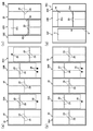
- (A) to (d) schematically show an example of the heat insulating wall panel, and (a) is a partially omitted schematic front view corresponding to the X1-X1 line arrow in FIG. 2, (b). 2 is a partially omitted schematic front view corresponding to the X2-X2 line arrow in FIG. 2, and (c) is a partially omitted schematic front view corresponding to the Y1-Y1 line arrow in FIG. 2, (d).
- A) is a partially broken schematic cross-sectional view schematically showing an example of the heat insulating wall panel
- (b) is a partially broken schematic cross-sectional view corresponding to the Z1 portion in FIG. 2
- (c) is.
- It is a partial fracture schematic cross-sectional view corresponding to the Z2 portion in FIG.
- FIGS. 1 to 6 are diagrams schematically showing an example of a heat insulating wall panel according to the present embodiment and an example of a unit house using the same.
- the heat insulating wall panel 20 includes a hard foamed resin base material 21 and surface materials 31 and 32 covering the hard foamed resin base material 21. There is. With such a configuration, damage to the hard foamed resin base material 21 can be suppressed by the surface materials 31 and 32. Further, in the present embodiment, the heat insulating wall panel 20 is configured to include the vacuum heat insulating material 29. With such a configuration, it is possible to improve the heat insulating property while reducing the thickness.
- the unit house 1 comprises a plurality of heat insulating wall panels 20 according to the present embodiment, each of which faces in the thickness direction constitutes an outer wall surface 30b and an inner wall surface 30a.
- the walls 30 are constructed so as to be arranged side by side in the width direction of the panel to partition the indoor and outdoor areas.
- the wall (first wall) 30 constituting the outer wall surface 30b and the inner wall surface 30a can be constructed by the heat insulating wall panel (first heat insulating wall panel) 20, and a plurality of plate-shaped members can be formed. It is not necessary to construct through various substrates and the like, and the workability can be improved.
- This unit house 1 is temporarily or simply used as an office such as a construction site or a construction site, a temporary housing in a disaster area, or a temporary store, a temporary office, or an event facility installed in various places. It may be installed as a target. Further, the unit house 1 may be a so-called prefabricated house or a trunk room. Further, the installation mode of the unit house 1 is not limited to the mode in which it is installed as a single unit, but may be a mode in which it is installed by being stacked vertically or arranged side by side in the horizontal direction.
- the unit house 1 includes a plurality of types of heat insulating wall panels 20, 20A to 20F.
- the unit house 1 includes a first heat insulating wall panel 20 containing the vacuum heat insulating material 29, and a second heat insulating wall panel 20A containing the vacuum heat insulating material 29 and having a single wiring box 28 provided on the lower end side. I have.
- the unit house 1 includes a third heat insulating wall panel 20B in which the vacuum heat insulating material 29 is included and a plurality of (two in the example) wiring boxes 28 are provided on the lower end side, and the vacuum heat insulating material 29 is included.
- the unit house 1 includes a fifth heat insulating wall panel 20D containing the vacuum heat insulating material 29 and having an opening 19, a sixth heat insulating wall panel 20E not provided with the vacuum heat insulating material 29, and the vacuum heat insulating material 29. It is provided with a seventh heat insulating wall panel 20F, which is not provided and has an entrance / exit 9.
- the common configuration of the heat insulating wall panels 20, 20A to 20F will be described below by taking the first heat insulating wall panel 20 as an example.
- the first heat insulating wall panel 20 has a substantially rectangular flat plate shape.
- the first heat insulating wall panel 20 has an elongated shape in the vertical direction.
- the panel height dimension (length dimension) of the first heat insulating wall panel 20 may be appropriately set according to the ceiling height of the unit house 1 in which the first heat insulating wall panel 20 is provided. For example, from 1800 mm to It may be about 3000 mm.
- the panel width dimension along the wall width direction of the first heat insulating wall panel 20 may be an appropriate dimension from the viewpoint of handleability and workability, and may be, for example, about 300 mm to 1800 mm.
- the thickness dimension of the first heat insulating wall panel 20 may be an appropriate size from the viewpoint of heat insulating property, weight reduction and cost reduction, and may be, for example, about 50 mm to 120 mm.
- the first heat insulating wall panel 20 has a configuration in which a joint protrusion 20a that protrudes outward in the panel width direction and extends in the panel height direction is provided at the first end portion in the panel width direction. Further, the first heat insulating wall panel 20 opens toward the outside in the panel width direction and extends in the panel height direction at the second end portion in the panel width direction, and the joint protrusion 20a of the adjacent first heat insulating wall panels 20 is fitted. It is configured to be provided with a joint recessed groove 20b to be inserted.
- the joint protrusion 20a can be fitted into the joint recess 20b to join the first heat insulating wall panels 20, 20 adjacent to each other in the panel width direction, and the end faces are butted against each other for joining. It is possible to suppress the displacement along the panel thickness direction and the occurrence of gaps as compared with the above.
- the rigid foamed resin base material 21 of the first heat insulating wall panel 20 is provided at the first end portion in the width direction of the panel so as to form an inner layer of the joint protrusion 20a partitioned by the surface materials 31 and 32.
- the unit 22 is provided. Further, in the hard foamed resin base material 21, the groove bottom pieces provided on the surface materials 31 and 32 so that the concave groove side end portion 23 as the second end portion in the panel width direction divides the groove bottom of the joint concave groove 20b.
- the portions 31 g and 32 g are in contact with the inside in the panel width direction. With such a configuration, as shown in FIG.
- a hard foamed resin is formed inside the joint protrusion 20a for joining the first heat insulating wall panels 20 to each other and inside the groove bottom of the joint concave groove 20b in the panel width direction.
- the system base material 21 will be present. Thereby, for example, the heat insulating property at the joint can be improved as compared with the case where the joint portion for joining the heat insulating wall panels is made of only a metal material or the joint portion is provided with a large hollow portion.
- the surface materials 31 and 32 include sheet metal. With such a configuration, damage to the hard foamed resin base material 21 can be suppressed more effectively. Further, the surface materials 31 and 32 are bent so as to partition the joint protrusion 20a and the joint recess 20b. With such a configuration, since the joint protrusion 20a and the joint recess 20b are composed of the surface materials 31 and 32 including the sheet metal formed by bending, the strength at the joint can be improved. Further, the surface materials 31 and 32 are provided with a gap between the tip of the joint protrusion 20a and the groove bottom of the joint recessed groove 20b in the panel thickness direction, and the first surface material 31 and one side in the panel thickness direction. A second surface material 32 on the other side in the panel thickness direction is provided.
- the surface materials 31 and 32 including the sheet metal can be compared with the surface material provided so as to form the entire surface of the tip of the joint protrusion 20a and the entire surface of the groove bottom of the joint concave groove 20b. It is possible to suppress the formation of a thermal bridge, and the heat insulating property can be improved more effectively.
- the hard foamed resin base material 21 is a foamed (foamed) heat insulating material whose main material is a synthetic resin such as a phenol resin, a urethane resin, a polystyrene resin, a polyethylene resin, a polypropylene resin, or an epoxy resin.
- the hard foamed resin base material 21 occupies most of the first heat insulating wall panel 20, and the thickness may be, for example, about 80% to 99% of the thickness of the first heat insulating wall panel 20.
- the protrusion 22 provided at the first end portion of the hard foamed resin base material 21 in the panel width direction is provided so as to project outward in the panel width direction and extend in the panel height direction.
- the protrusion 22 is provided over the entire surface of the hard foamed resin base material 21 in the panel height direction. Further, as shown in FIG. 5A, the protrusion 22 is provided at the center in the panel thickness direction in correspondence with the joint protrusion 20a in the present embodiment. Further, the protrusion 22 is a substantially flat surface whose both side surfaces in the panel thickness direction are substantially parallel to each surface in the thickness direction of the first heat insulating wall panel 20. Further, the tip surface 22a of the protrusion 22 facing outward in the panel width direction is a substantially flat surface substantially orthogonal to both side surfaces in the panel thickness direction.
- the side end surface 23a of the concave groove side end portion 23 of the hard foamed resin base material 21 facing outward in the panel width direction is a substantially flat surface substantially orthogonal to each surface in the thickness direction of the first heat insulating wall panel 20. Has been done.
- the first surface material 31 and the second surface material 32 are formed in a thin plate shape from various metal-based materials such as a stainless steel plate and an aluminum alloy plate.
- the first surface material 31 and the second surface material 32 may be, for example, surface-treated steel sheets that have been subjected to surface treatment such as rust prevention such as hot-dip galvanized steel sheets (SGCC).
- SGCC hot-dip galvanized steel sheets
- the thickness dimensions of the first surface material 31 and the second surface material 32 may be appropriate dimensions from the viewpoint of strength and weight reduction, and may be, for example, about 0.2 mm to 3 mm. It may be 1 mm or less. In the present embodiment, as shown in FIG.
- the material 32 and the material 32 have substantially the same structure as each other.
- An interior finishing layer may be provided on the surface of the first surface material 31 constituting the inner wall surface 30a by appropriate painting or attachment of a surface decorative sheet or the like.
- an exterior finishing layer may be provided on the surface of the second surface material 32 constituting the outer wall surface 30b by appropriate painting or attachment of a surface decorative sheet or the like.
- the first surface material 31 and the second surface material 32 include surface plate portions 31a and 32a forming each surface in the thickness direction of the first heat insulating wall panel 20. These surface plate portions 31a and 32a are provided along each surface of the hard foamed resin base material 21 in the thickness direction. Further, in the present embodiment, as shown in FIGS. 4 and 6, the lower end portion of the surface plate portion 32a of the second surface material 32 extends downward from the lower end surface of the hard foamed resin base material 21.
- the extension piece portion 32h to be extended is provided. The extending piece portion 32h is provided over substantially the entire surface plate portion 32a in the panel width direction.
- first surface material 31 and the second surface material 32 have end face covering piece portions 31b, 32b extending from the first end portion in the panel width direction of the surface plate portions 31a, 32a toward the center side in the panel thickness direction.
- the end face covering pieces 31b and 32b cover the end faces facing outward in the panel width direction on both sides in the panel thickness direction connected to the protrusion 22 base end side of the rigid foam resin base material 21, and are in contact with each end face. It is provided so as to be close to each other.
- first surface material 31 and the second surface material 32 have side covering pieces 31c, 32c extending outward in the panel width direction from the center side end in the panel thickness direction of the end face covering pieces 31b, 32b. I have.
- the side covering pieces 31c and 32c are provided so as to cover both side surfaces of the protrusion 22 of the rigid foam resin base material 21 in the panel thickness direction and to abut or approach each side surface, and the joint protrusions are provided. Both sides of the panel 20a in the panel thickness direction are partitioned.
- first surface material 31 and the second surface material 32 have tip covering pieces 31d and 32d extending from the outer end portions of the side covering pieces 31c and 32c in the panel width direction toward the center side in the panel thickness direction.
- the tip covering pieces 31d and 32d are provided so as to cover both side portions of the tip surface 22a of the protrusion 22 of the rigid foam resin base material 21 in the panel thickness direction and to abut or approach the tip surface 22a.
- the tip side of the joint protrusion 20a is partitioned.
- the dimensions of the tip covering pieces 31d and 32d along the panel thickness direction are from the viewpoint of suppressing damage to the protruding corners of the protrusions 22 of the rigid foam resin base material 21 and from the viewpoint of reducing the weight, and these tip covering pieces.
- the dimensions may be appropriate from the viewpoint of preventing the portions 31d and 32d from forming a thermal bridge.
- the dimensions of the tip covering pieces 31d and 32d along the panel thickness direction are smaller than the dimensions of the tip surface 22a of the protrusion 22 along the panel thickness direction.
- it may be about 2 mm to 10 mm.
- the dimensions of the tip covering pieces 31d and 32d along the panel thickness direction may be set so as to cover most of the tip surface 22a of the protrusion 22.
- the tip surface 22a of the protrusion 22 may be provided with a step portion corresponding to the thickness of the tip covering pieces 31d and 32d so that the tip surface of the joint protrusion 20a is substantially flat. ..
- the second end portion in the panel width direction is directed outward in the panel width direction from the side end surface 23a of the hard foamed resin base material 21. It is provided to extend.
- the first surface material 31 and the second surface material 32 include end face piece portions 31e and 32e extending from the second end portion of the surface plate portions 31a and 32a in the panel width direction toward the center side in the panel thickness direction. ing.
- the end face piece portions 31e and 32e form the end face of the second end portion in the panel width direction of the first heat insulating wall panel 20, and form the end face covering piece portions 31b and 32b of the first heat insulating wall panel 20 adjacent to each other when joined. Abutment or proximity (see FIG. 5B).
- first surface material 31 and the second surface material 32 are groove side walls extending from the end face pieces 31e, 32e at the center side in the panel thickness direction toward the center side in the panel width direction (side end face 23a side). It is provided with one piece 31f and 32f.
- the groove side wall pieces 31f and 32f partition both sides of the joint concave groove 20b in the groove width direction, and when they are joined, they come into contact with or are brought into contact with or close to the side covering pieces 31c and 32c of the adjacent first heat insulating wall panel 20. (See FIG. 5 (b)).
- the groove side wall piece portions 31f, 32f, the end face piece portions 31e, 32e, the extending portions of the surface plate portions 31a, 32a, and the hard foamed resin base material 21 A hollow portion penetrating in the panel height direction is provided, which is defined by the side end surface 23a of the above.
- this hollow portion may be used as a wiring space.
- the structure may be such that projecting portions are provided on both side edges of the concave groove side end portion 23 of the hard foamed resin base material 21 in the panel thickness direction.
- first surface material 31 and the second surface material 32 have groove bottom pieces 31g and 32g extending from the end of the groove side wall pieces 31f and 32f toward the center in the panel thickness direction. I have.
- the groove bottom pieces 31g and 32g are provided along the side end surface 23a of the hard foamed resin base material 21 to partition the groove bottom of the joint concave groove 20b.
- the dimensions of the groove bottom pieces 31g and 32g along the panel thickness direction are from the viewpoint of strength and weight reduction of the groove side wall pieces 31f and 32f that partition the joint concave groove 20b, and these groove bottom pieces 31g and 32g.
- the size may be appropriate from the viewpoint of suppressing the formation of a thermal bridge.
- the dimensions of the groove bottom pieces 31 g and 32 g along the panel thickness direction are shown as relatively small dimensions, and may be, for example, about 2 mm to 10 mm.
- the dimensions of the groove bottom pieces 31 g and 32 g along the panel thickness direction may be such that the groove bottom of the joint concave groove 20b is formed over most of the groove bottom.
- recesses corresponding to the thicknesses of the groove bottom pieces 31 g and 32 g are formed on the groove bottom of the joint recessed groove 20b, but the present invention is not limited to this aspect. ..
- the side end surface 23a of the hard foamed resin base material 21 may be provided with stepped portions corresponding to the thicknesses of the groove bottom pieces 31 g and 32 g so that the groove bottom of the joint concave groove 20b becomes a substantially flat surface. Good.
- the outer shape of the joint protrusion 20a is formed into a substantially rectangular shape when viewed in the panel height direction
- the joint concave groove 20b is formed into a substantially rectangular groove shape when viewed in the groove longitudinal direction.
- the outer shape of the joint protrusion 20a may be a substantially trapezoidal shape, a substantially triangular shape, a substantially U-shape, a substantially semicircular shape, or the like when viewed in the panel height direction, or may have various other shapes.
- the joint concave groove 20b may be appropriately deformed according to the outer shape of the joint protrusion 20a.
- an appropriate sealing member for sealing the joints between the adjacent first heat insulating wall panels 20 may be provided on both or one of the ends of the first heat insulating wall panel 20 in the panel width direction.
- first surface material 31 and the second surface material 32 may be fixed to the hard foamed resin base material 21 with a fastener such as a screw, an appropriate adhesive, an adhesive material or the like.
- a fastener such as a screw, an appropriate adhesive, an adhesive material or the like.
- the end face covering pieces 31b, 32b, the end face pieces 31e, 32e, and the like may be provided with holes for inserting the stoppers.
- the foamed resin-based material injected between the first surface material 31 and the second surface material 32 may be foamed and cured to form the hard foamed resin-based base material 21.
- gaps are provided between the tip covering pieces 31d and 32d and between the groove bottom pieces 31g and 32g of the first surface material 31 and the second surface material 32 is shown, but both are shown.
- a configuration in which one of the gaps is not provided may be used.
- both or one of the tip covering pieces 31d and 32d and the groove bottom pieces 31g and 32g may be integrally formed. That is, the first surface material 31 and the second surface material 32 may be provided in a series.
- the hard foamed resin-based base materials 21 and 21A of the first heat insulating wall panel 20 to the fifth heat insulating wall panel 20D containing the vacuum heat insulating material 29 are located indoors from the central portion in the thickness direction.
- the vacuum heat insulating material 29 is provided so as to be located. With such a configuration, it is possible to suppress damage to the vacuum heat insulating material 29 when an unintended impact or the like is applied from the outdoor side.
- the hard foamed resin base materials 21 and 21A are opened toward one side in the panel thickness direction, which is the indoor side, and the vacuum heat insulating material 29 is accommodated. It is configured to have a storage recess 24.
- the vacuum heat insulating material 29 may be fixed to the concave bottom surface of the accommodation recess 24 facing one side in the panel thickness direction with an appropriate adhesive, adhesive material, or the like. Further, the vacuum heat insulating material 29 is arranged so that one side surface in the thickness direction on the indoor side is in contact with or close to the back surface of the first surface material 31.
- the vacuum heat insulating material 29 has a substantially rectangular flat plate shape along the thickness direction in the panel thickness direction.
- the vacuum heat insulating material 29 may be formed by covering the core material with a gas barrier packaging material and vacuum suctioning.
- the core material may be made of a foam such as open-cell urethane foam, styrene foam, or phenol foam using a material having a relatively low thermal conductivity.
- the core material may be a crushed material of various foam materials, a powder or granular material such as silica, alumina, or pearlite, or a fiber material such as glass fiber, glass wool, rock wool, or cellulose fiber. ..
- the packaging material may be a metal film or the like having a gas barrier property.
- a film (sheet) may be used as a packaging material.
- the thickness dimension of the vacuum heat insulating material 29 may be an appropriate dimension from the viewpoint of desired heat insulating performance, cost, etc., and in the illustrated example, it is compared with the thickness dimension of the hard foamed resin base materials 21 and 21A. An example with a small size is shown, and for example, it may be about 5 mm to 20 mm. Further, the dimensions along the panel height direction and the dimensions along the panel width direction of the vacuum heat insulating material 29 may be appropriate dimensions from the viewpoint of desired heat insulating performance, cost and the like. The depth dimension along the panel thickness direction, the dimension along the panel height direction, and the dimension along the panel width direction of the accommodation recess 24 are appropriately set so that the vacuum heat insulating material 29 can be accommodated.
- FIG. 20 an example in which a plurality of vacuum heat insulating materials 29 are provided on the heat insulating wall panels 20, 20A to 20D is shown.
- four vacuum heat insulating materials 29 are provided on the first heat insulating wall panel 20, the second heat insulating wall panel 20A, the third heat insulating wall panel 20B, and the fourth heat insulating wall panel 20C, and the fifth heat insulating wall panel 20D is provided with four vacuum heat insulating materials 29.
- An example in which the two vacuum heat insulating materials 29 are provided is shown, but the present invention is not limited to such an embodiment.
- Each of the heat insulating wall panels 20, 20A to 20D may be configured to be provided with the vacuum heat insulating material 29 so that the area occupied by the vacuum heat insulating material 29 is halved or more when viewed in the panel thickness direction.
- the first heat insulating wall panel 20 is configured to be provided with the vacuum heat insulating material 29 so that the area occupied by the vacuum heat insulating material 29 in the panel thickness direction is approximately 80%.
- the second heat insulating wall panel 20A, the third heat insulating wall panel 20B, and the fourth heat insulating wall panel 20C provided with the wiring box 28 on the lower end side or the upper end side generally occupy the area occupied by the vacuum heat insulating material 29 in the panel thickness direction.
- the vacuum heat insulating material 29 is provided so as to be about 70%.
- the fifth heat insulating wall panel 20D provided with the opening 19 is vacuum heat-insulated so that the area occupied by the vacuum heat insulating material 29 is approximately 50% of the area viewed in the panel thickness direction excluding the opening area of the opening 19.
- the structure is such that the material 29 is provided.
- the layer of the hard foamed resin base material 21 and 21A instead of the mode in which the vacuum heat insulating material 29 is provided so as to be exposed on one side in the thickness direction on the indoor side of the hard foamed resin base material 21 and 21A, the layer of the hard foamed resin base material 21 and 21A. It may be configured to be embedded inside.
- the rigid foamed resin base material 21A of the second heat insulating wall panel 20A is formed deeper than the accommodating recess 24, and the accommodating groove 25 accommodating the tubular member 27 through which the cable is wired is accommodated.
- the accommodating groove 25 is provided so as to open at least on one side surface in the panel height direction. With such a configuration, the cable can be routed to the tubular member 27 through the opening on one side in the panel height direction, so that large-scale processing is not required at the construction site and the wiring workability is improved. be able to.
- the accommodating groove 25 is formed deeper than the accommodating recess 24 accommodating the vacuum heat insulating material 29, the tubular member 27 accommodated in the accommodating groove 25 may interfere with the vacuum heat insulating material 29. Can be suppressed.
- the hard foamed resin base material 21A of the second heat insulating wall panel 20A accommodates the wiring box 28 so as to be positioned according to the opening 31h provided in the surface material (first surface material) 31.
- the box storage recess 26 is provided so as to communicate with the storage groove 25.
- a switch (operation panel) connected to a cable routed via a tubular member 27, an outlet (plug-in connector), and the like can be installed in the wiring box 28.
- the accommodating groove 25 is provided so as to open toward one side in the panel thickness direction on the indoor side and extend in the panel height direction, and the first end portion (upper end portion) in the groove longitudinal direction is a hard foamed resin. It is open on the upper end surface of the system base material 21A.
- the accommodating groove 25 is provided so that at least a part of the accommodating groove 25 in the longitudinal direction of the groove opens at the concave bottom surface of the accommodating recess 24.
- the accommodating groove 25 is provided so as to vertically traverse the accommodating recess 24 in the panel height direction.
- the accommodating groove 25 is provided so as to vertically traverse one side of the two accommodating recesses 24 provided at intervals in the panel width direction.
- the accommodating groove 25 is provided so as to vertically traverse both of the two accommodating recesses 24 provided at a vertical interval on one side in the panel width direction.
- the accommodating groove 25 is provided at a position offset from the center of the hard foamed resin base material 21A in the panel width direction to one side in the panel width direction (protrusion 22 side in the drawing example).
- the depth dimension of the accommodating groove 25 along the panel thickness direction may be an appropriate dimension so that the tubular member 27 does not protrude from the concave bottom surface of the accommodating recess 24 at the portion of the accommodating recess 24.
- the groove width dimension of the accommodating groove 25 is set according to the outer diameter of the tubular member 27.
- the accommodating groove 25 is provided so that the second end portion (lower end portion) in the longitudinal direction of the groove is located at a portion on the lower end side of the hard foamed resin base material 21A where the accommodating recess 24 is not provided. There is.
- the tubular member 27 has a hollow tubular shape that penetrates in the longitudinal direction.
- the tubular member 27 may have a cylindrical shape, a polygonal tubular shape, a corrugated flexible tube (corrugated tube), or the like.
- the upper end of the tubular member 27 is located at the upper end of the hard foamed resin base material 21A, and the lower end is connected to the wiring box 28 housed in the box storage recess 26.
- the box storage recess 26 is opened toward one side in the panel thickness direction, which is the indoor side, at a portion of the hard foam resin base material 21A on the lower end side where the storage recess 24 is not provided.
- the depth dimension along the panel thickness direction, the dimension along the panel height direction, and the dimension along the panel width direction of the box accommodating recess 26 are appropriately set so that the wiring box 28 can be accommodated. ..
- the wiring box 28 has a substantially rectangular box shape that opens toward one side in the panel thickness direction on the indoor side, and has a configuration in which a through hole communicating with the tubular member 27 is provided in the upper side wall portion. ..
- the opening 31h provided in the first surface material 31 of the second heat insulating wall panel 20A is located at a position corresponding to the wiring box 28 when viewed in the panel thickness direction, so that the surface plate portion 31a of the first surface material 31 It is provided so as to penetrate the lower end side portion of the.
- FIGS. 3A and 3B show an example in which the wiring box 28 is provided so as to be located substantially at the center in the panel width direction, the wiring box 28 is provided at a position offset to one side in the panel width direction. It may be a thing.
- two wiring boxes 28, 28 are provided at the lower end side of the third heat insulating wall panel 20B at intervals in the panel width direction from the central portion in the panel width direction.
- the hard foamed resin base material 21 of the third heat insulating wall panel 20B is not shown, but is substantially the same as the second heat insulating wall panel 20A, and has a box accommodating recess for accommodating these wiring boxes 28 and 28, respectively. Place 26 is provided.
- the hard foamed resin base material 21 of the third heat insulating wall panel 20B is provided with two storage grooves 25 that communicate with each of the box storage recesses 26 and accommodate the tubular member 27 in each of them.
- the two wiring boxes 28, 28 are provided at substantially equal intervals in the panel width direction from the central portion in the panel width direction, but the present invention is not limited to this mode.
- a wiring box 28 is provided at a portion on the upper end side of the fourth heat insulating wall panel 20C at a substantially central portion in the panel width direction.
- the hard foamed resin base material 21 of the fourth heat insulating wall panel 20C is provided with a box accommodating recess 26 for accommodating the wiring box 28.
- the rigid foam resin base material 21 of the fourth heat insulating wall panel 20C is provided with a storage groove 25 that communicates with the box storage recess 26 and accommodates the tubular member 27.
- the accommodating groove 25 may be provided so as to extend in the panel height direction at a portion of the upper end side portion of the hard foamed resin base material 21 where the accommodating recess 24 is not provided, and may be opened at the upper end surface. In this case, the depth dimension of the accommodating groove 25 may be appropriately set so that the tubular member 27 does not protrude from the surface of the hard foamed resin base material 21 facing the indoor side.
- the opening 19 of the fifth heat insulating wall panel 20D is provided so as to penetrate the fifth heat insulating wall panel 20D in the thickness direction, and is provided at an intermediate portion in the panel height direction.
- the opening 19 is provided in the fifth heat insulating wall panel 20D so that the window member provided in the opening 19 constitutes a high-waisted window.
- the opening 19 is provided over substantially the entire panel width direction. That is, the fifth heat insulating wall panel 20D is configured to be divided into an upper end side portion 20c and a lower end side portion 20d by the opening 19. An appropriate window member may be installed in the opening 19.
- the sixth heat insulating wall panel 20E has a smaller panel width dimension than the above-mentioned heat insulating wall panels 20, 20A to 20D.
- the panel width dimensions of the heat insulating wall panels 20, 20A to 20D are substantially the same as each other, and the panel width dimension of the sixth heat insulating wall panel 20E is the panel width dimension of the heat insulating wall panels 20, 20A to 20D.
- An example of about 1/2 is shown.
- the sixth heat insulating wall panel 20E may also include the vacuum heat insulating material 29.
- the seventh heat insulating wall panel 20F is provided with a door body 8 for opening and closing the doorway 9.
- the door body 8 may be a hinged door in which the end portion on the door end side is rotatably held around an axis along the door height direction, or may be a folding door, a sliding door, or the like. Further, the door body 8 may be built on a door frame provided so as to partition the entrance / exit 9 of the 7th heat insulating wall panel 20F.
- the panel width dimension of the 7th heat insulating wall panel 20F is substantially the same as the panel width size of the heat insulating wall panels 20, 20A to 20D other than the 6th heat insulating wall panel 20E described above.
- the panel width dimensions of the heat insulating wall panels 20, 20A to 20F including the sixth heat insulating wall panel 20E may be substantially the same as each other, or may be different from each other.
- the thickness dimension and the panel height dimension of the heat insulating wall panels 20, 20A to 20F are substantially the same as each other.
- the seventh heat insulating wall panel 20F and the door body 8 may also include the vacuum heat insulating material 29.
- the wiring box 28, the box accommodating recess 26 accommodating the wiring box 28, the box accommodating recess 26 accommodating the wiring box 28, the tubular member 27, the accommodating groove 25, etc. May be provided.
- a through hole for attaching a ventilation device such as a ventilation fan, an insertion hole for inserting a cable connected to the ventilation device, or the like may be provided at an appropriate position on any of the heat insulating wall panels 20, 20A to 20F. ..
- a through hole or the like through which a duct connected to an air conditioner or a water supply / drainage facility can be inserted may be provided at an appropriate position on any of the heat insulating wall panels 20, 20A to 20F.
- the configurations of the heat insulating wall panels 20, 20A to 20F described above are not limited to those described above, and various other modifications are possible.
- the unit house 1 has a substantially rectangular shape that is long in one direction in a plan view.
- the area occupied by the vacuum heat insulating material 29 viewed in the panel thickness direction is 1 / of the total wall area obtained by adding the areas of the four peripheral walls 30, 30A to 30C viewed in each wall thickness direction.
- the heat insulating wall panels 20, 20A to 20F may be provided so as to have two or more.
- the first wall 30 and the second wall 30A which are arranged so as to face each other and form the long side side, each of the five heat insulating wall panels 20, 20A to 20C, each containing the vacuum heat insulating material 29.
- the example constructed by is shown.
- a plurality of heat insulating wall panels 20, 20A to 20C including the vacuum heat insulating material 29 are arranged side by side in the panel width direction to form a long side in one direction.
- the first wall 30 and the second wall 30A of the above are constructed.
- the third wall 30B and the fourth wall 30C which are arranged so as to face each other and form the short side side, are constructed by three heat insulating wall panels 20, 20D to 20F, respectively.
- the first wall 30 includes two first heat insulating wall panels 20, one second heat insulating wall panel 20A, and one third heat insulating wall panel 20B and 1. It is constructed by a fourth insulating wall panel 20C.
- the second wall 30A is constructed by three first heat insulating wall panels 20, one second heat insulating wall panel 20A and one third heat insulating wall panel 20B, as shown in FIGS. 2 and 3 (b). Has been done.
- the third wall 30B is constructed by one first heat insulating wall panel 20, one fifth heat insulating wall panel 20D, and one sixth heat insulating wall panel 20E. Has been done. As shown in FIGS.
- the fourth wall 30C is constructed by one fifth heat insulating wall panel 20D, one sixth heat insulating wall panel 20E, and one seventh heat insulating wall panel 20F.
- the number of heat insulating wall panels 20, 20A to 20F constituting each wall 30, 30A to 30C of the unit house 1, the arrangement location, and the combination mode are not limited to the mode shown in the figure, and various deformations may occur. It is possible.
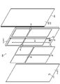
- the unit house 1 holds the upper frame 11 that holds the upper end portions of the heat insulating wall panels 20, 20A to 20F, and the lower end portions of the heat insulating wall panels 20, 20A to 20F. It includes a lower frame 13. With such a configuration, the upper and lower frames 11 and the lower frame 13 can hold the upper and lower ends of the heat insulating wall panels 20, 20A to 20F. As a result, the workability can be improved as compared with the case where a wall base arranged in the middle such as the furring strip is required. Further, as shown in FIGS. 1 and 5 (c), the unit house 1 includes a vertical frame 14 provided between the ends of the upper frame 11 and the lower frame 13 in the longitudinal direction.
- the vertical frame 14 is configured to hold the side ends of the heat insulating wall panels 20, 20C, 20E, and 20F arranged on the outermost side in the wall width direction in the wall width direction. With such a configuration, the side ends of the heat insulating wall panels 20, 20C, 20E, and 20F arranged on the outermost side in the wall width direction in the wall width direction can be held by the vertical frame 14. Since the holding modes of the heat insulating wall panels 20, 20A to 20F by the upper frame 11, the lower frame 13, and the vertical frame 14 are the same, the first heat insulating wall panel 20 will be described below as an example.
- the unit house 1 includes a heat insulating ceiling panel 6 held by an upper frame 11 arranged so as to surround four circumferences, a floor side heat insulating material 3 held by a lower frame 13 arranged so as to surround four circumferences, and the like. (See FIG. 6).
- a heat insulating ceiling panel 6 held by an upper frame 11 arranged so as to surround four circumferences
- a floor side heat insulating material 3 held by a lower frame 13 arranged so as to surround four circumferences, and the like.
- the heat insulating properties on the ceiling side and the floor side can be improved.
- the heat insulating ceiling panel 6 and the floor side heat insulating material 3 can be held by the upper frame 11 and the lower frame 13.
- the upper frame 11 has an elongated shape in the wall width direction, and has a substantially uniform cross-sectional shape over the entire length. As shown in FIG.
- the upper frame 11 is arranged along the thickness direction in the wall thickness direction, and includes a thin plate-shaped surface plate portion 11a extending in the wall width direction. Further, the upper frame 11 is provided so as to rise upward from the end portion of one portion extending from the lower end portion of the surface plate portion 11a toward the indoor side, and the upper end portion of the first heat insulating wall panel 20. It is provided with a contact portion 11b with which a contact is made. The second surface material 32 on the outdoor side of the first heat insulating wall panel 20 is brought into contact with the contact portion 11b. An appropriate sealing member may be interposed between the first heat insulating wall panel 20 and the contact portion 11b.
- the upper frame 11 is provided with a holding piece portion 11c for holding the tubular member 12 extending in the wall width direction.
- the holding piece portion 11c is provided so as to extend toward the indoor side from the upper end portion of the contact portion 11b.
- the upper frame 11 includes a rising piece portion 11d provided so as to stand up from an indoor end portion of the holding piece portion 11c.
- a concave groove that opens upward is partitioned by the rising piece portion 11d, the holding piece portion 11c, and the surface plate portion 11a, and the tubular member 12 is arranged in the concave groove.
- various cables may be wired in the tubular member 12.
- the structure may be such that the tubular member 12 is not provided, or the structure may be integrally provided on the upper frame 11.
- the upper frame 11 includes a panel holding piece portion 11e that extends from the upper end portion of the rising piece portion 11d toward the indoor side and holds the heat insulating ceiling panel 6.
- the rising piece portion 11d and the panel holding piece portion 11e are provided separately from the holding piece portion 11c, but the configuration may be such that they are provided integrally.
- the outer peripheral end of the heat insulating ceiling panel 6 is placed on the panel holding piece 11e and held on the upper frame 11.
- the heat-insulating ceiling panel 6 may be fixed to the panel holding piece 11e with a fastener such as a screw, an appropriate adhesive, an adhesive material, or the like.
- the heat-insulating ceiling panel 6 is a foam-based (foam-based) heat-insulating material similar to the above-mentioned hard foamed resin-based base material 21.
- the heat insulating ceiling panel 6 may be configured not to include the vacuum heat insulating material 29 as described above. Further, the heat insulating ceiling panel 6 may be configured not to have a surface material including a sheet metal as described above.
- An interior finishing layer may be provided on the lower surface of the heat-insulating ceiling panel 6 facing the indoor side by appropriate painting or attachment of a surface decorative sheet or the like. Further, in the illustrated example, the thickness dimension of the heat insulating ceiling panel 6 is set to be smaller than the thickness dimension of the first heat insulating wall panel 20, but the present invention is not limited to this aspect.
- a ceiling-side heat insulating material 7 is further provided on the upper side of the heat-insulating ceiling panel 6.
- the ceiling-side heat insulating material 7 may be a fiber-based heat insulating material containing mineral fibers such as glass wool and rock wool.
- the thickness dimension of the ceiling-side heat insulating material 7 is larger than the thickness dimension of the heat insulating ceiling panel 6 and the first heat insulating wall panel 20 is shown. Not limited.
- the ceiling-side heat insulating material 7 may be placed and held on the heat-insulating ceiling panel 6, and is provided so as to extend from the upper end of the surface plate portion 11a of the upper frame 11 toward the indoor side. It may be fixed and held by an appropriate stopper or the like on the tip end portion 11f of the extending portion. Further, an appropriate roofing material may be provided so as to cover the upper side of the ceiling side heat insulating material 7. Further, the roofing material may be fixed to the upper frame 11.
- the peripheral edge 18 arranged at the inner corner of the first heat insulating wall panel 20 and the heat insulating ceiling panel 6 is provided.
- the peripheral edge 18 is arranged along the thickness direction in the wall thickness direction, and includes a holding piece portion 18a that comes into contact with the first surface material 31 on the indoor side of the first heat insulating wall panel 20.
- the peripheral edge 18 is provided so as to extend from the upper end portion of the holding piece portion 18a toward the indoor side, and includes a ceiling side piece portion 18b that abuts on the lower surface of the heat insulating ceiling panel 6.
- the peripheral edge 18 may be fixed to at least one of the heat insulating ceiling panel 6, the first heat insulating wall panel 20, and the upper frame 11 by an appropriate fastener, adhesive, adhesive material, or the like. Further, the peripheral edge 18 is provided along each of the four peripheral walls 30, 30A to 30C of the unit house 1 on the indoor side. Further, the peripheral edge 18 is provided so that each end portion in the longitudinal direction does not interfere with the corner member 17 described later.
- the peripheral edge 18 may function as a holding portion for holding the upper end portion of the first heat insulating wall panel 20 together with the upper frame 11. Further, as a mode for holding the upper end portion of the first heat insulating wall panel 20, the upper frame 11 is provided with a receiving groove that opens downward to receive and hold the upper end portion of the first heat insulating wall panel 20. It may be an aspect. Further, the upper end portion of the first heat insulating wall panel 20 may be fixed to the upper frame 11 by a fastener, an adhesive, an adhesive, a magnet, or the like to hold the upper end portion of the first heat insulating wall panel 20. Various other modifications are possible as a mode for holding the upper end portion.
- each end of the upper frames 11 and 11 and the upper end of the vertical frame 14 may be fixed to the upper end connecting member 15 by an appropriate stopper. Further, if the stopper is removed, the upper frames 11, 11, the vertical frame 14, and the upper end connecting member 15 may be easily disassembled. In FIG. 6, the upper end connecting member 15 and the lower end connecting member 16 described later are not shown.
- the cube-shaped frame unit 10 is composed of the upper frame 11, the lower frame 13, the vertical frame 14, the upper end connecting member 15, and the lower end connecting member 16.
- the lower frame 13 has an elongated shape in the wall width direction and has a substantially uniform cross-sectional shape over the entire length. As shown in FIG. 6, the lower frame 13 is arranged along the thickness direction in the wall thickness direction, and includes a thin plate-shaped surface plate portion 13a extending in the wall width direction. The surface plate portion 13a is arranged at a position substantially coincident with the surface plate portion 11a of the upper frame 11 in the wall thickness direction in the state where the unit house 1 is assembled. Further, the lower frame 13 includes a base portion 13b extending from the lower end portion of the surface plate portion 13a toward the indoor side. The base portion 13b is brought into contact with an appropriate installation target 2, and the unit house 1 is installed. Further, the lower frame 13 extends toward the indoor side from the upper end portion of one portion provided so as to rise upward from the indoor side end portion of the base portion 13b, and holds the floor side heat insulating material 3. The holding piece portion 13c is provided.
- the floor-side heat insulating material 3 has an outer peripheral end portion placed on the holding piece portion 13c and held on the lower frame 13.
- the floor-side heat insulating material 3 may be fixed to the holding piece portion 13c with a fastener such as a screw, an appropriate adhesive, an adhesive material, or the like.
- the floor-side heat insulating material 3 is a foam-based (foam-based) heat insulating material similar to the above-mentioned hard foamed resin base material 21.
- the floor side heat insulating material 3 may be configured not to include the vacuum heat insulating material 29 as described above. Further, the floor-side heat insulating material 3 may be configured not to have a surface material including a sheet metal as described above.
- the thickness dimension of the floor-side heat insulating material 3 is substantially the same as the thickness dimension of the first heat insulating wall panel 20, but the present invention is not limited to this mode.
- the lower frame 13 includes a panel holding piece portion 13d extending from the upper end portion of the surface plate portion 13a toward the indoor side.
- a protrusion 13e is provided in the middle portion of the panel holding piece portion 13d in the wall thickness direction so as to project upward and abut the lower end surface of the first heat insulating wall panel 20.
- the protrusion 13e is provided so as to extend over the entire length of the lower frame 13. If such a protrusion 13e is provided, it is possible to suppress the intrusion of rainwater or the like into the indoor side.
- the protruding portion 13e has a substantially flat upper side surface when viewed in the longitudinal direction of the lower frame 13.
- the protruding dimension of the protruding portion 13e along the vertical direction is substantially the same as the dimension along the vertical direction of the extending piece portion 32h of the first heat insulating wall panel 20 arranged on the outdoor side of the protruding portion 13e. ..
- An appropriate sealing member may be interposed between the first heat insulating wall panel 20 and the lower frame 13.
- the lower end portion of the first heat insulating wall panel 20 may be placed and held on the lower frame 13, or may be fixed by a fastener such as a screw, an appropriate adhesive, an adhesive or the like. It may be.
- a floor holding piece portion 13f extending from the base end portion (lower end portion) of the protruding portion 13e toward the indoor side and holding the floor base material 4 is provided. It is provided.
- the outer peripheral end of the floor base material 4 is placed on the floor holding piece 13f and held by the lower frame 13.
- the floor base material 4 may be fixed to the floor holding piece portion 13f with a fastener such as a screw, an appropriate adhesive, an adhesive material, or the like.
- the floor base material 4 may be, for example, a wood laminated board such as plywood or LVL (single board laminated material), or a floor base board such as a wood board such as particle board.
- the floor finishing material 5 is laminated on the floor base material 4.
- the floor finishing material 5 may be a so-called wood-based flooring formed from a wood-based material and formed into a panel shape, and may be any kind such as a so-called cushion floor, floor tiles, and carpet.
- the floor finishing material 5 may be a separate body from the floor base material 4 and may be constructed at the construction site, or may be laminated and integrated on the floor base material 4 in advance.
- the outer peripheral end portions of the floor base material 4 and the floor finishing material 5 are arranged so as to be inserted between the floor holding piece portion 13f and the lower end surface of the first heat insulating wall panel 20.
- the mode for holding the lower end portion of the first heat insulating wall panel 20, the floor base material 4 and the floor finishing material 5 on the outer peripheral side is not limited to the above mode, and various other modifications are possible.
- four lower frames 13 are provided along the lower ends of the four walls 30, 30A to 30C of the unit house 1.
- the lower end connecting members 16 for connecting the longitudinal end portions of the lower frames 13 and 13 adjacent to each other and the lower end portions of the vertical frame 14 are provided at the four corners.
- Each end of the lower frames 13 and 13 and the lower end of the vertical frame 14 may be fixed to the lower end connecting member 16 by an appropriate stopper as described above. Further, if the stopper is removed, the lower frames 13, 13, the vertical frame 14, and the lower end connecting member 16 may be easily disassembled.
- the vertical frames 14 are provided at the four corners of the unit house 1.
- the vertical frame 14 is elongated in the vertical direction and has a substantially uniform cross-sectional shape over the entire length.
- the vertical frame 14 includes surface plate portions 14a and 14a which are orthogonal to each other so as to form a corner portion on the outer shell side of the unit house 1. These surface plate portions 14a and 14a have a thin plate shape that extends in each of the longitudinal direction and the lateral direction of the unit house 1 and extends in the vertical direction.
- these surface plate portions 14a and 14a have substantially the same planar shape as the surface plate portions 11a and 13a of the upper frame 11 and the lower frame 13 which are arranged in parallel with each other in the assembled state of the unit house 1. Arranged to be. Further, the vertical frame 14 extends so as to be folded back from the indoor end of one of the surface plate portions 14a, 14a extending toward the indoor side from the opposite corner side ends. The contact portions 14b and 14b are provided. The side ends of the first heat insulating wall panels 20 and 20 forming the corners on the corner side in the panel width direction are brought into contact with the contact portions 14b and 14b.
- the first heat insulating wall panels 20 and 20 constituting these corner portions are provided with the corner members 17 arranged at the entrance corners on the indoor side.
- the corner members 17 are orthogonal to each other so as to form an indoor entrance portion of the unit house 1, and come into contact with the first surface materials 31 and 31 on the indoor side of the first heat insulating wall panels 20 and 20. It is provided with holding pieces 17a and 17a to be pressed. With such a configuration in which the corner member 17 is provided, it is possible to cover the gap formed in the inside corner portion between the first heat insulating wall panels 20 and 20 constituting the corner portion.
- the corner member 17 may be fixed to at least one of the first heat insulating wall panel 20 and the vertical frame 14 by an appropriate fastener, adhesive, adhesive material, or the like. Further, the corner members 17 are provided at each of the four indoor corners of the unit house 1.
- the corner member 17 may function as a holding portion for holding the side ends of the first heat insulating wall panels 20 and 20 together with the vertical frame 14. Further, as a mode for holding the side ends of the first heat insulating wall panels 20 and 20 constituting the corner portion, the vertical frame 14 accepts and holds the side ends of the first heat insulating wall panels 20 and 20. A mode may be provided in which a receiving groove that opens in the wall width direction is provided. Further, each side end portion of the first heat insulating wall panels 20 and 20 may be fixed to the vertical frame 14 by a fastener, an adhesive, an adhesive material, a magnet, or the like to hold each side end portion. Various other modifications are possible as a mode for holding the side end portion.
- peripheral edge 18 and the corner member 17 may be formed of an appropriate metal-based material or synthetic resin-based material.
- the frame unit 10 provided with the above-mentioned upper frame 11, lower frame 13, vertical frame 14, upper end connecting member 15 and lower end connecting member 16 may be formed of an appropriate metal-based material.
- the unit house 1 having the above-described configuration may be constructed as follows, for example. First, the four lower frames 13 are connected by the lower end connecting member 16, and the lower ends of the vertical frames 14 at the four corners are connected to the lower end connecting member 16. Further, the four upper frames 11 are connected to the upper end connecting members 15 connected to the upper ends of the vertical frames 14 at the four corners to assemble the frame unit 10.
- the frame unit 10 is not limited to the one assembled at the installation location of the unit house 1, and may be assembled in advance at an appropriate location and carried into the installation location.
- the floor side heat insulating material 3, the floor base material 4, and the floor finishing material 5 are constructed, the heat insulating wall panels 20, 20A to 20F are constructed, and the heat insulating ceiling panel 6, the ceiling side heat insulating material 7, the roof material, etc. are constructed. You may try to do it. Further, the corner member 17, the peripheral edge 18, and the like may be constructed. The above construction procedure is only an example, and various modifications are possible. Further, the unit house 1 may have a structure that can be disassembled (disassembled) and reassembled.
- the wiring box 28 and the tubular member 27 are embedded in at least one of the plurality of heat insulating wall panels 20, 20A to 20F constituting the unit house 1 is shown.
- the wiring box 28 and the tubular member 27 may not be embedded.
- the accommodating groove 25 of the tubular member 27 and the box accommodating recess 26 of the wiring box 28 may not be provided in the rigid foam resin base material 21A.
- the heat insulating ceiling panel 6 and the floor side heat insulating material 3 are provided in the unit house 1 is shown, but one or both of these may not be provided.
- the upper frame 11, the lower frame 13, and the vertical frame 14 are provided in the unit house 1 is shown, but at least one or all of these is not provided. May be good.
- an appropriate base material or the like for holding each end of the heat insulating wall panels 20, 20A to 20F may be provided.
- the heat insulating wall panels 20, 20A to 20F constitute the unit house 1 is shown, but the present invention is not limited to such an embodiment.
- the heat insulating wall panels 20, 20A to 20F according to the present embodiment are not limited to the unit house 1, and can be used as walls of various buildings. Further, the configuration of each member and each part used in the heat insulating wall panels 20, 20A to 20F according to the present embodiment is not limited to the above-described embodiment, and various other modifications are possible.
Abstract
An insulated wall panel 20 comprising a rigid foam resin substrate 21 and surface material 31, 32 that covers the rigid foam resin substrate, wherein: a first end in the panel width direction is provided with a joining protrusion 20a that extends in the panel height direction and that projects toward the outside in the panel width direction, and a second end in the panel width direction is provided with a joining groove 20b that opens toward the outside in the panel width direction, that extends in the panel height direction, and into which the joining protrusion of an adjacent insulated wall panel fits; and the rigid foam resin substrate comprises a protrusion 22 provided on the first end in the panel width direction so as to constitute an inner layer of the joining protrusion demarcated by the surface material, and the second end in the panel width direction abuts, in the panel width direction, the interior side of a groove bottom part 31g, 32g that is provided on the surface material so as to demarcate the groove bottom of the joining groove.
Description
本発明は、断熱壁パネル及びこれを備えたユニットハウスに関する。
The present invention relates to a heat insulating wall panel and a unit house provided with the same.
従来より、建物やコンテナ等の壁に設けられる断熱パネルが知られている。
例えば、下記特許文献1には、表面側パネルと裏面側パネルとの間に断熱用の発泡スチロールを充填した断熱パネルが開示されている。また、この断熱パネルは、パネル幅方向両端部に、表面側パネル及び裏面側パネルによってパネル厚さ方向両側を区画する凹溝を設けた構成とされている。 Conventionally, heat insulating panels provided on walls of buildings, containers, and the like have been known.
For example, Patent Document 1 below discloses a heat insulating panel in which styrofoam for heat insulating is filled between the front surface side panel and the back surface side panel. Further, this heat insulating panel has a configuration in which recessed grooves are provided at both ends in the panel width direction to partition both sides in the panel thickness direction by a front surface side panel and a back surface side panel.
しかしながら、上記特許文献1に記載されたような断熱パネルでは、パネル幅方向に複数枚の断熱パネルを並設する際に、凹溝を区画する表面側パネルの端面同士及び裏面側パネルの端面同士を突き合わせて接合する構成となる。そのため、接合部において位置ずれ等が生じ易く、また、互いの凹溝によって接合部に大きな中空部が形成され、断熱性の観点から更なる改善が望まれる。
However, in the heat insulating panel as described in Patent Document 1, when a plurality of heat insulating panels are arranged side by side in the panel width direction, the end faces of the front panel and the end faces of the back panel for partitioning the concave groove are arranged side by side. It is configured to butt and join. Therefore, misalignment or the like is likely to occur in the joint portion, and a large hollow portion is formed in the joint portion by the concave grooves of each other, and further improvement is desired from the viewpoint of heat insulation.
本発明は、上記実情に鑑みてなされたものであり、施工性を向上させながらも、断熱性を向上し得る断熱壁パネル及びこれを備えたユニットハウスを提供することを目的としている。
The present invention has been made in view of the above circumstances, and an object of the present invention is to provide a heat insulating wall panel capable of improving heat insulating property while improving workability, and a unit house provided with the heat insulating wall panel.
上記目的を達成するために、本発明に係る断熱壁パネルは、硬質発泡樹脂系基材と、この硬質発泡樹脂系基材を覆う表面材と、を備えた断熱壁パネルであって、パネル幅方向第1端部には、パネル幅方向外側に向けて突出しパネル高さ方向に延びる接合突部が設けられ、パネル幅方向第2端部には、パネル幅方向外側に向けて開口しパネル高さ方向に延び、隣り合う断熱壁パネルの接合突部が嵌め入れられる接合凹溝が設けられており、前記硬質発泡樹脂系基材は、パネル幅方向第1端部に、前記表面材によって区画された前記接合突部の内層を構成するように設けられた突部を備え、パネル幅方向第2端部が前記接合凹溝の溝底を区画するように前記表面材に設けられた溝底片部のパネル幅方向内側に当接されていることを特徴とする。
In order to achieve the above object, the heat insulating wall panel according to the present invention is a heat insulating wall panel including a hard foamed resin base material and a surface material covering the hard foamed resin base material, and has a panel width. The first end in the direction is provided with a joint protrusion that protrudes outward in the panel width direction and extends in the panel height direction, and the second end in the panel width direction is opened toward the outside in the panel width direction and the panel height. A joint recessed groove extending in the vertical direction and into which the joint protrusions of adjacent heat insulating wall panels are fitted is provided, and the rigid foamed resin base material is partitioned by the surface material at the first end portion in the panel width direction. A groove bottom piece provided on the surface material so as to have a protrusion provided so as to form an inner layer of the joint protrusion and a second end portion in the panel width direction partitions the groove bottom of the joint recess. It is characterized in that the portion is in contact with the inside in the panel width direction.
また、上記目的を達成するために、本発明に係るユニットハウスは、本発明に係る断熱壁パネルを複数枚備えており、厚さ方向の各面が外壁面及び内壁面を構成するように、これら複数枚の断熱壁パネルがパネル幅方向に並設されて屋内外を区画する壁が構築されることを特徴とする。
Further, in order to achieve the above object, the unit house according to the present invention is provided with a plurality of heat insulating wall panels according to the present invention so that each surface in the thickness direction constitutes an outer wall surface and an inner wall surface. It is characterized in that a plurality of these heat insulating wall panels are arranged side by side in the panel width direction to construct a wall for partitioning indoors and outdoors.
本発明に係る断熱壁パネル及びこれを備えたユニットハウスは、上述のような構成としたことで、施工性を向上させながらも、断熱性を向上させることができる。
The heat insulating wall panel according to the present invention and the unit house provided with the heat insulating wall panel have the above-mentioned configuration, so that the heat insulating property can be improved while improving the workability.
以下に本発明の実施の形態について、図面に基づいて説明する。
なお、一部の図では、他図に付している詳細な符号の一部を省略している。
また、以下の実施形態では、本実施形態に係る断熱壁パネル及びユニットハウスを施工した状態を基準として上下方向等の方向を説明する。
図1~図6は、本実施形態に係る断熱壁パネルの一例及びこれを用いたユニットハウスの一例を模式的に示す図である。 Hereinafter, embodiments of the present invention will be described with reference to the drawings.
In some figures, some of the detailed symbols attached to the other figures are omitted.
Further, in the following embodiment, the vertical direction and the like will be described with reference to the state in which the heat insulating wall panel and the unit house according to the present embodiment are constructed.
1 to 6 are diagrams schematically showing an example of a heat insulating wall panel according to the present embodiment and an example of a unit house using the same.
本実施形態に係る断熱壁パネル20は、図5(a)に示すように、硬質発泡樹脂系基材21と、この硬質発泡樹脂系基材21を覆う表面材31,32と、を備えている。このような構成とすれば、表面材31,32によって硬質発泡樹脂系基材21の損傷等を抑制することができる。また、本実施形態では、この断熱壁パネル20に、真空断熱材29を内包させた構成としている。このような構成とすれば、薄型化を図りながらも断熱性を向上させることができる。
As shown in FIG. 5A, the heat insulating wall panel 20 according to the present embodiment includes a hard foamed resin base material 21 and surface materials 31 and 32 covering the hard foamed resin base material 21. There is. With such a configuration, damage to the hard foamed resin base material 21 can be suppressed by the surface materials 31 and 32. Further, in the present embodiment, the heat insulating wall panel 20 is configured to include the vacuum heat insulating material 29. With such a configuration, it is possible to improve the heat insulating property while reducing the thickness.
本実施形態に係るユニットハウス1は、図1~図3に示すように、複数枚の本実施形態に係る断熱壁パネル20を、厚さ方向の各面が外壁面30b及び内壁面30aを構成するように、パネル幅方向に並設して屋内外を区画する壁30が構築される構成とされている。このような構成とすれば、断熱壁パネル(第1断熱壁パネル)20によって外壁面30b及び内壁面30aを構成する壁(第1壁)30を構築することができ、複数の板状部材を種々の下地等を介して施工する必要がなく、施工性を向上させることができる。
このユニットハウス1は、工事現場や建設現場等の事務所や、被災地等における仮設住宅、その他、種々の箇所に設置される仮店舗や仮事務所、イベント施設等の用途として一時的や簡易的に設置されるものでもよい。また、ユニットハウス1は、いわゆるプレハブハウスやトランクルームであってもよい。また、ユニットハウス1の設置態様としては、単体で設置される態様に限られず、上下に積み重ねられたり、水平方向に並設されたりして設置される態様でもよい。 As shown in FIGS. 1 to 3, the unit house 1 according to the present embodiment comprises a plurality of heat insulatingwall panels 20 according to the present embodiment, each of which faces in the thickness direction constitutes an outer wall surface 30b and an inner wall surface 30a. As such, the walls 30 are constructed so as to be arranged side by side in the width direction of the panel to partition the indoor and outdoor areas. With such a configuration, the wall (first wall) 30 constituting the outer wall surface 30b and the inner wall surface 30a can be constructed by the heat insulating wall panel (first heat insulating wall panel) 20, and a plurality of plate-shaped members can be formed. It is not necessary to construct through various substrates and the like, and the workability can be improved.
This unit house 1 is temporarily or simply used as an office such as a construction site or a construction site, a temporary housing in a disaster area, or a temporary store, a temporary office, or an event facility installed in various places. It may be installed as a target. Further, the unit house 1 may be a so-called prefabricated house or a trunk room. Further, the installation mode of the unit house 1 is not limited to the mode in which it is installed as a single unit, but may be a mode in which it is installed by being stacked vertically or arranged side by side in the horizontal direction.
このユニットハウス1は、工事現場や建設現場等の事務所や、被災地等における仮設住宅、その他、種々の箇所に設置される仮店舗や仮事務所、イベント施設等の用途として一時的や簡易的に設置されるものでもよい。また、ユニットハウス1は、いわゆるプレハブハウスやトランクルームであってもよい。また、ユニットハウス1の設置態様としては、単体で設置される態様に限られず、上下に積み重ねられたり、水平方向に並設されたりして設置される態様でもよい。 As shown in FIGS. 1 to 3, the unit house 1 according to the present embodiment comprises a plurality of heat insulating
This unit house 1 is temporarily or simply used as an office such as a construction site or a construction site, a temporary housing in a disaster area, or a temporary store, a temporary office, or an event facility installed in various places. It may be installed as a target. Further, the unit house 1 may be a so-called prefabricated house or a trunk room. Further, the installation mode of the unit house 1 is not limited to the mode in which it is installed as a single unit, but may be a mode in which it is installed by being stacked vertically or arranged side by side in the horizontal direction.
本実施形態では、ユニットハウス1は、図3に示すように、複数種類の断熱壁パネル20,20A~20Fを備えている。ユニットハウス1は、真空断熱材29を内包した第1断熱壁パネル20と、真空断熱材29を内包し、かつ単一の配線ボックス28を下端側に設けた第2断熱壁パネル20Aと、を備えている。また、ユニットハウス1は、真空断熱材29を内包し、かつ複数(図例では2つ)の配線ボックス28を下端側に設けた第3断熱壁パネル20Bと、真空断熱材29を内包し、かつ単一の配線ボックス28を上端側に設けた第4断熱壁パネル20Cと、を備えている。また、ユニットハウス1は、真空断熱材29を内包し、かつ開口19を設けた第5断熱壁パネル20Dと、真空断熱材29を設けていない第6断熱壁パネル20Eと、真空断熱材29を設けておらず、かつ出入口9を設けた第7断熱壁パネル20Fと、を備えている。なお、各断熱壁パネル20,20A~20Fにおける共通の構成について、以下、第1断熱壁パネル20を例にとって説明する。
In the present embodiment, as shown in FIG. 3, the unit house 1 includes a plurality of types of heat insulating wall panels 20, 20A to 20F. The unit house 1 includes a first heat insulating wall panel 20 containing the vacuum heat insulating material 29, and a second heat insulating wall panel 20A containing the vacuum heat insulating material 29 and having a single wiring box 28 provided on the lower end side. I have. Further, the unit house 1 includes a third heat insulating wall panel 20B in which the vacuum heat insulating material 29 is included and a plurality of (two in the example) wiring boxes 28 are provided on the lower end side, and the vacuum heat insulating material 29 is included. It also includes a fourth heat insulating wall panel 20C provided with a single wiring box 28 on the upper end side. Further, the unit house 1 includes a fifth heat insulating wall panel 20D containing the vacuum heat insulating material 29 and having an opening 19, a sixth heat insulating wall panel 20E not provided with the vacuum heat insulating material 29, and the vacuum heat insulating material 29. It is provided with a seventh heat insulating wall panel 20F, which is not provided and has an entrance / exit 9. The common configuration of the heat insulating wall panels 20, 20A to 20F will be described below by taking the first heat insulating wall panel 20 as an example.
第1断熱壁パネル20は、略方形平板状とされている。この第1断熱壁パネル20は、上下方向に長尺状とされている。この第1断熱壁パネル20のパネル高さ寸法(長さ寸法)は、当該第1断熱壁パネル20が設けられるユニットハウス1の天井高に応じて適宜の寸法とすればよく、例えば、1800mm~3000mm程度としてもよい。また、第1断熱壁パネル20の壁幅方向に沿うパネル幅寸法は、取扱性や施工性の観点等から適宜の寸法としてもよく、例えば、300mm~1800mm程度としてもよい。また、第1断熱壁パネル20の厚さ寸法は、断熱性の観点や、軽量化及び低コスト化を図る観点等から適宜の寸法としてもよく、例えば、50mm~120mm程度としてもよい。
The first heat insulating wall panel 20 has a substantially rectangular flat plate shape. The first heat insulating wall panel 20 has an elongated shape in the vertical direction. The panel height dimension (length dimension) of the first heat insulating wall panel 20 may be appropriately set according to the ceiling height of the unit house 1 in which the first heat insulating wall panel 20 is provided. For example, from 1800 mm to It may be about 3000 mm. Further, the panel width dimension along the wall width direction of the first heat insulating wall panel 20 may be an appropriate dimension from the viewpoint of handleability and workability, and may be, for example, about 300 mm to 1800 mm. Further, the thickness dimension of the first heat insulating wall panel 20 may be an appropriate size from the viewpoint of heat insulating property, weight reduction and cost reduction, and may be, for example, about 50 mm to 120 mm.
第1断熱壁パネル20は、本実施形態では、パネル幅方向第1端部にパネル幅方向外側に向けて突出しパネル高さ方向に延びる接合突部20aを設けた構成とされている。また、第1断熱壁パネル20は、パネル幅方向第2端部に、パネル幅方向外側に向けて開口しパネル高さ方向に延び、隣り合う第1断熱壁パネル20の接合突部20aが嵌め入れられる接合凹溝20bを設けた構成とされている。このような構成とすれば、接合突部20aを接合凹溝20bに嵌め入れてパネル幅方向に隣り合う第1断熱壁パネル20,20同士を接合することができ、端面同士を突き合わせて接合するようなものと比べて、パネル厚さ方向に沿う位置ずれや、隙間が生じるようなことを抑制することができる。
In the present embodiment, the first heat insulating wall panel 20 has a configuration in which a joint protrusion 20a that protrudes outward in the panel width direction and extends in the panel height direction is provided at the first end portion in the panel width direction. Further, the first heat insulating wall panel 20 opens toward the outside in the panel width direction and extends in the panel height direction at the second end portion in the panel width direction, and the joint protrusion 20a of the adjacent first heat insulating wall panels 20 is fitted. It is configured to be provided with a joint recessed groove 20b to be inserted. With such a configuration, the joint protrusion 20a can be fitted into the joint recess 20b to join the first heat insulating wall panels 20, 20 adjacent to each other in the panel width direction, and the end faces are butted against each other for joining. It is possible to suppress the displacement along the panel thickness direction and the occurrence of gaps as compared with the above.
この第1断熱壁パネル20の硬質発泡樹脂系基材21は、パネル幅方向第1端部に、表面材31,32によって区画された接合突部20aの内層を構成するように設けられた突部22を備えている。また、硬質発泡樹脂系基材21は、パネル幅方向第2端部としての凹溝側端部23が接合凹溝20bの溝底を区画するように表面材31,32に設けられた溝底片部31g,32gのパネル幅方向内側に当接されている。このような構成とすれば、図5(b)に示すように、第1断熱壁パネル20同士を接合する接合突部20a内及び接合凹溝20bの溝底のパネル幅方向内側に硬質発泡樹脂系基材21が存在することとなる。これにより、例えば、断熱壁パネル同士を接合する接合部を金属材のみで構成したものや接合部に大きな中空部が設けられるものと比べて、接合部における断熱性を向上させることができる。
The rigid foamed resin base material 21 of the first heat insulating wall panel 20 is provided at the first end portion in the width direction of the panel so as to form an inner layer of the joint protrusion 20a partitioned by the surface materials 31 and 32. The unit 22 is provided. Further, in the hard foamed resin base material 21, the groove bottom pieces provided on the surface materials 31 and 32 so that the concave groove side end portion 23 as the second end portion in the panel width direction divides the groove bottom of the joint concave groove 20b. The portions 31 g and 32 g are in contact with the inside in the panel width direction. With such a configuration, as shown in FIG. 5B, a hard foamed resin is formed inside the joint protrusion 20a for joining the first heat insulating wall panels 20 to each other and inside the groove bottom of the joint concave groove 20b in the panel width direction. The system base material 21 will be present. Thereby, for example, the heat insulating property at the joint can be improved as compared with the case where the joint portion for joining the heat insulating wall panels is made of only a metal material or the joint portion is provided with a large hollow portion.
また、表面材31,32は、板金を含んでいる。このような構成とすれば、硬質発泡樹脂系基材21の損傷等をより効果的に抑制することができる。また、表面材31,32は、接合突部20a及び接合凹溝20bを区画するように折曲形成されている。このような構成とすれば、接合突部20a及び接合凹溝20bが折曲形成された板金を含んだ表面材31,32によって構成されるので、接合部における強度を向上させることができる。
また、表面材31,32は、接合突部20aの先端及び接合凹溝20bの溝底においてパネル厚さ方向に互いに隙間を空けて設けられたパネル厚さ方向一方側の第1表面材31及びパネル厚さ方向他方側の第2表面材32を備えている。このような構成とすれば、表面材を接合突部20aの先端の全面や接合凹溝20bの溝底の全面を構成するように設けたものと比べて、板金を含む表面材31,32が熱橋(ヒートブリッジ)となるようなことを抑制することができ、断熱性をより効果的に向上させることができる。 Further, the surface materials 31 and 32 include sheet metal. With such a configuration, damage to the hard foamed resin base material 21 can be suppressed more effectively. Further, the surface materials 31 and 32 are bent so as to partition the joint protrusion 20a and the joint recess 20b. With such a configuration, since the joint protrusion 20a and the joint recess 20b are composed of the surface materials 31 and 32 including the sheet metal formed by bending, the strength at the joint can be improved.
Further, the surface materials 31 and 32 are provided with a gap between the tip of the joint protrusion 20a and the groove bottom of the joint recessed groove 20b in the panel thickness direction, and the first surface material 31 and one side in the panel thickness direction. A second surface material 32 on the other side in the panel thickness direction is provided. With such a configuration, the surface materials 31 and 32 including the sheet metal can be compared with the surface material provided so as to form the entire surface of the tip of the joint protrusion 20a and the entire surface of the groove bottom of the joint concave groove 20b. It is possible to suppress the formation of a thermal bridge, and the heat insulating property can be improved more effectively.
また、表面材31,32は、接合突部20aの先端及び接合凹溝20bの溝底においてパネル厚さ方向に互いに隙間を空けて設けられたパネル厚さ方向一方側の第1表面材31及びパネル厚さ方向他方側の第2表面材32を備えている。このような構成とすれば、表面材を接合突部20aの先端の全面や接合凹溝20bの溝底の全面を構成するように設けたものと比べて、板金を含む表面材31,32が熱橋(ヒートブリッジ)となるようなことを抑制することができ、断熱性をより効果的に向上させることができる。 Further, the
Further, the
硬質発泡樹脂系基材21は、フェノール樹脂や、ウレタン樹脂、ポリスチレン樹脂、ポリエチレン樹脂、ポリプロピレン樹脂、エポキシ樹脂等の合成樹脂を主材とする発泡系(フォーム系)断熱材とされている。この硬質発泡樹脂系基材21は、第1断熱壁パネル20の大部分を占め、例えば、厚さが第1断熱壁パネル20の厚さの80%~99%程度であってもよい。
この硬質発泡樹脂系基材21のパネル幅方向第1端部に設けられた突部22は、パネル幅方向外側に向けて突出し、かつパネル高さ方向に延びるように設けられている。この突部22は、硬質発泡樹脂系基材21のパネル高さ方向の全体に亘って設けられている。また、この突部22は、図5(a)に示すように、本実施形態では、接合突部20aに対応させてパネル厚さ方向中央部に設けられている。また、突部22は、パネル厚さ方向両側面が第1断熱壁パネル20の厚さ方向各面に略平行状の略平坦面とされている。また、突部22のパネル幅方向外側に向く先端面22aは、パネル厚さ方向両側面に対して略直交状の略平坦面とされている。
この硬質発泡樹脂系基材21の凹溝側端部23のパネル幅方向外側に向く側端面23aは、第1断熱壁パネル20の厚さ方向各面に対して略直交状の略平坦面とされている。 The hard foamedresin base material 21 is a foamed (foamed) heat insulating material whose main material is a synthetic resin such as a phenol resin, a urethane resin, a polystyrene resin, a polyethylene resin, a polypropylene resin, or an epoxy resin. The hard foamed resin base material 21 occupies most of the first heat insulating wall panel 20, and the thickness may be, for example, about 80% to 99% of the thickness of the first heat insulating wall panel 20.
Theprotrusion 22 provided at the first end portion of the hard foamed resin base material 21 in the panel width direction is provided so as to project outward in the panel width direction and extend in the panel height direction. The protrusion 22 is provided over the entire surface of the hard foamed resin base material 21 in the panel height direction. Further, as shown in FIG. 5A, the protrusion 22 is provided at the center in the panel thickness direction in correspondence with the joint protrusion 20a in the present embodiment. Further, the protrusion 22 is a substantially flat surface whose both side surfaces in the panel thickness direction are substantially parallel to each surface in the thickness direction of the first heat insulating wall panel 20. Further, the tip surface 22a of the protrusion 22 facing outward in the panel width direction is a substantially flat surface substantially orthogonal to both side surfaces in the panel thickness direction.
Theside end surface 23a of the concave groove side end portion 23 of the hard foamed resin base material 21 facing outward in the panel width direction is a substantially flat surface substantially orthogonal to each surface in the thickness direction of the first heat insulating wall panel 20. Has been done.
この硬質発泡樹脂系基材21のパネル幅方向第1端部に設けられた突部22は、パネル幅方向外側に向けて突出し、かつパネル高さ方向に延びるように設けられている。この突部22は、硬質発泡樹脂系基材21のパネル高さ方向の全体に亘って設けられている。また、この突部22は、図5(a)に示すように、本実施形態では、接合突部20aに対応させてパネル厚さ方向中央部に設けられている。また、突部22は、パネル厚さ方向両側面が第1断熱壁パネル20の厚さ方向各面に略平行状の略平坦面とされている。また、突部22のパネル幅方向外側に向く先端面22aは、パネル厚さ方向両側面に対して略直交状の略平坦面とされている。
この硬質発泡樹脂系基材21の凹溝側端部23のパネル幅方向外側に向く側端面23aは、第1断熱壁パネル20の厚さ方向各面に対して略直交状の略平坦面とされている。 The hard foamed
The
The
第1表面材31及び第2表面材32は、ステンレス鋼板やアルミニウム合金板等の種々の金属系材料から薄板状に形成されている。これら第1表面材31及び第2表面材32は、例えば、溶融亜鉛めっき鋼板(SGCC)等の防錆等の表面処理加工が施された表面処理鋼板であってもよい。また、これら第1表面材31及び第2表面材32の厚さ寸法は、強度上の観点や軽量化を図る観点等から適宜の寸法としてもよく、例えば、0.2mm~3mm程度としてもよく、1mm以下としてもよい。
本実施形態では、図5(a)に示すように、パネル厚さ方向一方側の屋内側に配される第1表面材31とパネル厚さ方向他方側の屋外側に配される第2表面材32とを、互いに概ね同様の構成としている。なお、内壁面30aを構成する第1表面材31の表面には、適宜の塗装や表面化粧シート等の貼着によって内装仕上層が設けられていてもよい。また、外壁面30bを構成する第2表面材32の表面には、適宜の塗装や表面化粧シート等の貼着によって外装仕上層が設けられていてもよい。 Thefirst surface material 31 and the second surface material 32 are formed in a thin plate shape from various metal-based materials such as a stainless steel plate and an aluminum alloy plate. The first surface material 31 and the second surface material 32 may be, for example, surface-treated steel sheets that have been subjected to surface treatment such as rust prevention such as hot-dip galvanized steel sheets (SGCC). Further, the thickness dimensions of the first surface material 31 and the second surface material 32 may be appropriate dimensions from the viewpoint of strength and weight reduction, and may be, for example, about 0.2 mm to 3 mm. It may be 1 mm or less.
In the present embodiment, as shown in FIG. 5A, thefirst surface material 31 arranged on the indoor side on one side in the panel thickness direction and the second surface arranged on the outdoor side on the other side in the panel thickness direction. The material 32 and the material 32 have substantially the same structure as each other. An interior finishing layer may be provided on the surface of the first surface material 31 constituting the inner wall surface 30a by appropriate painting or attachment of a surface decorative sheet or the like. Further, an exterior finishing layer may be provided on the surface of the second surface material 32 constituting the outer wall surface 30b by appropriate painting or attachment of a surface decorative sheet or the like.
本実施形態では、図5(a)に示すように、パネル厚さ方向一方側の屋内側に配される第1表面材31とパネル厚さ方向他方側の屋外側に配される第2表面材32とを、互いに概ね同様の構成としている。なお、内壁面30aを構成する第1表面材31の表面には、適宜の塗装や表面化粧シート等の貼着によって内装仕上層が設けられていてもよい。また、外壁面30bを構成する第2表面材32の表面には、適宜の塗装や表面化粧シート等の貼着によって外装仕上層が設けられていてもよい。 The
In the present embodiment, as shown in FIG. 5A, the
これら第1表面材31及び第2表面材32は、第1断熱壁パネル20の厚さ方向の各面を構成する表面板部31a,32aを備えている。これら表面板部31a,32aは、硬質発泡樹脂系基材21の厚さ方向の各面に沿うように設けられている。
また、本実施形態では、図4及び図6に示すように、第2表面材32の表面板部32aの下端部に、硬質発泡樹脂系基材21の下端面よりも下方側に向けて延出する延出片部32hを設けた構成としている。この延出片部32hは、表面板部32aのパネル幅方向の概ね全体に亘って設けられている。
また、第1表面材31及び第2表面材32は、表面板部31a,32aのパネル幅方向第1端部からパネル厚さ方向中心側に向けて延出する端面覆い片部31b,32bを備えている。端面覆い片部31b,32bは、硬質発泡樹脂系基材21の突部22基端側に連なるパネル厚さ方向両側のパネル幅方向外側に向く端面を覆うように、かつ各端面に当接または近接するように設けられている。
また、第1表面材31及び第2表面材32は、端面覆い片部31b,32bのパネル厚さ方向中心側端部からパネル幅方向外側に向けて延出する側面覆い片部31c,32cを備えている。側面覆い片部31c,32cは、硬質発泡樹脂系基材21の突部22のパネル厚さ方向両側面を覆うように、かつ各側面に当接または近接するように設けられており、接合突部20aのパネル厚さ方向両側を区画する。 Thefirst surface material 31 and the second surface material 32 include surface plate portions 31a and 32a forming each surface in the thickness direction of the first heat insulating wall panel 20. These surface plate portions 31a and 32a are provided along each surface of the hard foamed resin base material 21 in the thickness direction.
Further, in the present embodiment, as shown in FIGS. 4 and 6, the lower end portion of thesurface plate portion 32a of the second surface material 32 extends downward from the lower end surface of the hard foamed resin base material 21. The extension piece portion 32h to be extended is provided. The extending piece portion 32h is provided over substantially the entire surface plate portion 32a in the panel width direction.
Further, thefirst surface material 31 and the second surface material 32 have end face covering piece portions 31b, 32b extending from the first end portion in the panel width direction of the surface plate portions 31a, 32a toward the center side in the panel thickness direction. I have. The end face covering pieces 31b and 32b cover the end faces facing outward in the panel width direction on both sides in the panel thickness direction connected to the protrusion 22 base end side of the rigid foam resin base material 21, and are in contact with each end face. It is provided so as to be close to each other.
Further, thefirst surface material 31 and the second surface material 32 have side covering pieces 31c, 32c extending outward in the panel width direction from the center side end in the panel thickness direction of the end face covering pieces 31b, 32b. I have. The side covering pieces 31c and 32c are provided so as to cover both side surfaces of the protrusion 22 of the rigid foam resin base material 21 in the panel thickness direction and to abut or approach each side surface, and the joint protrusions are provided. Both sides of the panel 20a in the panel thickness direction are partitioned.
また、本実施形態では、図4及び図6に示すように、第2表面材32の表面板部32aの下端部に、硬質発泡樹脂系基材21の下端面よりも下方側に向けて延出する延出片部32hを設けた構成としている。この延出片部32hは、表面板部32aのパネル幅方向の概ね全体に亘って設けられている。
また、第1表面材31及び第2表面材32は、表面板部31a,32aのパネル幅方向第1端部からパネル厚さ方向中心側に向けて延出する端面覆い片部31b,32bを備えている。端面覆い片部31b,32bは、硬質発泡樹脂系基材21の突部22基端側に連なるパネル厚さ方向両側のパネル幅方向外側に向く端面を覆うように、かつ各端面に当接または近接するように設けられている。
また、第1表面材31及び第2表面材32は、端面覆い片部31b,32bのパネル厚さ方向中心側端部からパネル幅方向外側に向けて延出する側面覆い片部31c,32cを備えている。側面覆い片部31c,32cは、硬質発泡樹脂系基材21の突部22のパネル厚さ方向両側面を覆うように、かつ各側面に当接または近接するように設けられており、接合突部20aのパネル厚さ方向両側を区画する。 The
Further, in the present embodiment, as shown in FIGS. 4 and 6, the lower end portion of the
Further, the
Further, the
また、第1表面材31及び第2表面材32は、側面覆い片部31c,32cのパネル幅方向外側端部からパネル厚さ方向中心側に向けて延出する先端覆い片部31d,32dを備えている。先端覆い片部31d,32dは、硬質発泡樹脂系基材21の突部22の先端面22aのパネル厚さ方向両側部位を覆うように、かつ先端面22aに当接または近接するように設けられており、接合突部20aの先端側を区画する。先端覆い片部31d,32dのパネル厚さ方向に沿う寸法は、硬質発泡樹脂系基材21の突部22の両側出隅部の損傷を抑制する観点や軽量化を図る観点、これら先端覆い片部31d,32dが熱橋となることを抑制する観点等から適宜の寸法としてもよい。図例では、先端覆い片部31d,32dのパネル厚さ方向に沿う寸法を、突部22の先端面22aのパネル厚さ方向に沿う寸法に比して小さい寸法とした例を示しており、例えば、2mm~10mm程度としてもよい。なお、このような態様に代えて、先端覆い片部31d,32dのパネル厚さ方向に沿う寸法を、突部22の先端面22aを大半に亘って覆うような寸法等としてもよい。また、図例では、接合突部20aの先端部に先端覆い片部31d,32dの厚さに応じた凹所が形成される構成とした例を示しているが、このような態様に限られない。例えば、突部22の先端面22aに先端覆い片部31d,32dの厚さに応じた突段部を設けて接合突部20aの先端面が概ね平坦面状となるような構成等としてもよい。
Further, the first surface material 31 and the second surface material 32 have tip covering pieces 31d and 32d extending from the outer end portions of the side covering pieces 31c and 32c in the panel width direction toward the center side in the panel thickness direction. I have. The tip covering pieces 31d and 32d are provided so as to cover both side portions of the tip surface 22a of the protrusion 22 of the rigid foam resin base material 21 in the panel thickness direction and to abut or approach the tip surface 22a. The tip side of the joint protrusion 20a is partitioned. The dimensions of the tip covering pieces 31d and 32d along the panel thickness direction are from the viewpoint of suppressing damage to the protruding corners of the protrusions 22 of the rigid foam resin base material 21 and from the viewpoint of reducing the weight, and these tip covering pieces. The dimensions may be appropriate from the viewpoint of preventing the portions 31d and 32d from forming a thermal bridge. In the illustrated example, an example is shown in which the dimensions of the tip covering pieces 31d and 32d along the panel thickness direction are smaller than the dimensions of the tip surface 22a of the protrusion 22 along the panel thickness direction. For example, it may be about 2 mm to 10 mm. Instead of such an embodiment, the dimensions of the tip covering pieces 31d and 32d along the panel thickness direction may be set so as to cover most of the tip surface 22a of the protrusion 22. Further, in the illustrated example, an example is shown in which recesses corresponding to the thicknesses of the tip covering pieces 31d and 32d are formed at the tip of the joint protrusion 20a, but the configuration is limited to such a mode. Absent. For example, the tip surface 22a of the protrusion 22 may be provided with a step portion corresponding to the thickness of the tip covering pieces 31d and 32d so that the tip surface of the joint protrusion 20a is substantially flat. ..
また、第1表面材31及び第2表面材32の表面板部31a,32aは、パネル幅方向第2端部が硬質発泡樹脂系基材21の側端面23aよりもパネル幅方向外側に向けて延出するように設けられている。また、第1表面材31及び第2表面材32は、表面板部31a,32aのパネル幅方向第2端部からパネル厚さ方向中心側に向けて延出する端面片部31e,32eを備えている。端面片部31e,32eは、第1断熱壁パネル20のパネル幅方向第2端部の端面を構成し、接合された際に隣り合う第1断熱壁パネル20の端面覆い片部31b,32bに当接または近接される(図5(b)参照)。
Further, in the surface plate portions 31a and 32a of the first surface material 31 and the second surface material 32, the second end portion in the panel width direction is directed outward in the panel width direction from the side end surface 23a of the hard foamed resin base material 21. It is provided to extend. Further, the first surface material 31 and the second surface material 32 include end face piece portions 31e and 32e extending from the second end portion of the surface plate portions 31a and 32a in the panel width direction toward the center side in the panel thickness direction. ing. The end face piece portions 31e and 32e form the end face of the second end portion in the panel width direction of the first heat insulating wall panel 20, and form the end face covering piece portions 31b and 32b of the first heat insulating wall panel 20 adjacent to each other when joined. Abutment or proximity (see FIG. 5B).
また、第1表面材31及び第2表面材32は、端面片部31e,32eのパネル厚さ方向中心側端部からパネル幅方向中心側(側端面23a側)に向けて延出する溝側壁片部31f,32fを備えている。溝側壁片部31f,32fは、接合凹溝20bの溝幅方向両側を区画し、接合された際に隣り合う第1断熱壁パネル20の側面覆い片部31c,32cに当接または近接される(図5(b)参照)。第1断熱壁パネル20のパネル幅方向第2端部には、溝側壁片部31f,32f、端面片部31e,32e、表面板部31a,32aの延出部及び硬質発泡樹脂系基材21の側端面23aによって区画されたパネル高さ方向に貫通する中空部が設けられている。なお、この中空部を、配線スペースとして利用するようにしてもよい。また、このような中空部が形成されないように、硬質発泡樹脂系基材21の凹溝側端部23のパネル厚さ方向両側縁部に突出部を設けたような構成等としてもよい。
Further, the first surface material 31 and the second surface material 32 are groove side walls extending from the end face pieces 31e, 32e at the center side in the panel thickness direction toward the center side in the panel width direction (side end face 23a side). It is provided with one piece 31f and 32f. The groove side wall pieces 31f and 32f partition both sides of the joint concave groove 20b in the groove width direction, and when they are joined, they come into contact with or are brought into contact with or close to the side covering pieces 31c and 32c of the adjacent first heat insulating wall panel 20. (See FIG. 5 (b)). At the second end portion of the first heat insulating wall panel 20 in the panel width direction, the groove side wall piece portions 31f, 32f, the end face piece portions 31e, 32e, the extending portions of the surface plate portions 31a, 32a, and the hard foamed resin base material 21 A hollow portion penetrating in the panel height direction is provided, which is defined by the side end surface 23a of the above. In addition, this hollow portion may be used as a wiring space. Further, in order to prevent such a hollow portion from being formed, the structure may be such that projecting portions are provided on both side edges of the concave groove side end portion 23 of the hard foamed resin base material 21 in the panel thickness direction.
また、第1表面材31及び第2表面材32は、溝側壁片部31f,32fのパネル幅方向中心側端部からパネル厚さ方向中心側に向けて延出する溝底片部31g,32gを備えている。溝底片部31g,32gは、硬質発泡樹脂系基材21の側端面23aに沿うように設けられ、接合凹溝20bの溝底を区画する。溝底片部31g,32gのパネル厚さ方向に沿う寸法は、接合凹溝20bを区画する溝側壁片部31f,32f等の強度上の観点や軽量化を図る観点、これら溝底片部31g,32gが熱橋となることを抑制する観点等から適宜の寸法としてもよい。図例では、溝底片部31g,32gのパネル厚さ方向に沿う寸法を、比較的に小さい寸法とした例を示しており、例えば、2mm~10mm程度としてもよい。なお、このような態様に代えて、溝底片部31g,32gのパネル厚さ方向に沿う寸法を、接合凹溝20bの溝底を大半に亘って構成するような寸法等としてもよい。また、図例では、接合凹溝20bの溝底に溝底片部31g,32gの厚さに応じた凹所が形成される構成とした例を示しているが、このような態様に限られない。例えば、硬質発泡樹脂系基材21の側端面23aに溝底片部31g,32gの厚さに応じた突段部を設けて接合凹溝20bの溝底が概ね平坦面状となる構成等としてもよい。
Further, the first surface material 31 and the second surface material 32 have groove bottom pieces 31g and 32g extending from the end of the groove side wall pieces 31f and 32f toward the center in the panel thickness direction. I have. The groove bottom pieces 31g and 32g are provided along the side end surface 23a of the hard foamed resin base material 21 to partition the groove bottom of the joint concave groove 20b. The dimensions of the groove bottom pieces 31g and 32g along the panel thickness direction are from the viewpoint of strength and weight reduction of the groove side wall pieces 31f and 32f that partition the joint concave groove 20b, and these groove bottom pieces 31g and 32g. The size may be appropriate from the viewpoint of suppressing the formation of a thermal bridge. In the illustrated example, the dimensions of the groove bottom pieces 31 g and 32 g along the panel thickness direction are shown as relatively small dimensions, and may be, for example, about 2 mm to 10 mm. Instead of such an embodiment, the dimensions of the groove bottom pieces 31 g and 32 g along the panel thickness direction may be such that the groove bottom of the joint concave groove 20b is formed over most of the groove bottom. Further, in the illustrated example, an example is shown in which recesses corresponding to the thicknesses of the groove bottom pieces 31 g and 32 g are formed on the groove bottom of the joint recessed groove 20b, but the present invention is not limited to this aspect. .. For example, the side end surface 23a of the hard foamed resin base material 21 may be provided with stepped portions corresponding to the thicknesses of the groove bottom pieces 31 g and 32 g so that the groove bottom of the joint concave groove 20b becomes a substantially flat surface. Good.
また、本実施形態では、接合突部20aの外郭形状をパネル高さ方向に見て略方形状とし、接合凹溝20bを溝長手方向に見て略方形溝状とした例を示しているが、このような態様に限られない。例えば、接合突部20aの外郭形状をパネル高さ方向に見て略台形状や略三角形状、略U字形状、略半円形状等としてもよく、その他、種々の形状としてもよい。この場合は、接合凹溝20bを接合突部20aの外郭形状に応じて適宜、変形するようにすればよい。
また、第1断熱壁パネル20のパネル幅方向の各端部の両方または一方に、隣接する第1断熱壁パネル20同士の接合部をシールする適宜のシール部材を設けた構成としてもよい。 Further, in the present embodiment, an example is shown in which the outer shape of thejoint protrusion 20a is formed into a substantially rectangular shape when viewed in the panel height direction, and the joint concave groove 20b is formed into a substantially rectangular groove shape when viewed in the groove longitudinal direction. , The mode is not limited to this. For example, the outer shape of the joint protrusion 20a may be a substantially trapezoidal shape, a substantially triangular shape, a substantially U-shape, a substantially semicircular shape, or the like when viewed in the panel height direction, or may have various other shapes. In this case, the joint concave groove 20b may be appropriately deformed according to the outer shape of the joint protrusion 20a.
Further, an appropriate sealing member for sealing the joints between the adjacent first heat insulatingwall panels 20 may be provided on both or one of the ends of the first heat insulating wall panel 20 in the panel width direction.
また、第1断熱壁パネル20のパネル幅方向の各端部の両方または一方に、隣接する第1断熱壁パネル20同士の接合部をシールする適宜のシール部材を設けた構成としてもよい。 Further, in the present embodiment, an example is shown in which the outer shape of the
Further, an appropriate sealing member for sealing the joints between the adjacent first heat insulating
また、第1表面材31及び第2表面材32は、ねじ等の止具や適宜の接着剤、粘着材等によって硬質発泡樹脂系基材21に固定されるものでもよい。この場合は、例えば、端面覆い片部31b,32bや端面片部31e,32e等に止具の挿通孔を設けた構成等としてもよい。または、第1表面材31と第2表面材32との間に注入された発泡樹脂系材料が発泡、硬化して硬質発泡樹脂系基材21が形成されたものでもよい。
また、本実施形態では、第1表面材31及び第2表面材32の先端覆い片部31d,32d間及び溝底片部31g,32g間のそれぞれに隙間を設けた例を示しているが、両方または一方の隙間を設けていない構成としてもよい。この場合は、例えば、先端覆い片部31d,32d及び溝底片部31g,32gの両方または一方が一体的に形成されたものでもよい。つまり、第1表面材31と第2表面材32とが一連状に設けられたものでもよい。 Further, thefirst surface material 31 and the second surface material 32 may be fixed to the hard foamed resin base material 21 with a fastener such as a screw, an appropriate adhesive, an adhesive material or the like. In this case, for example, the end face covering pieces 31b, 32b, the end face pieces 31e, 32e, and the like may be provided with holes for inserting the stoppers. Alternatively, the foamed resin-based material injected between the first surface material 31 and the second surface material 32 may be foamed and cured to form the hard foamed resin-based base material 21.
Further, in the present embodiment, an example in which gaps are provided between the tip covering pieces 31d and 32d and between the groove bottom pieces 31g and 32g of the first surface material 31 and the second surface material 32 is shown, but both are shown. Alternatively, a configuration in which one of the gaps is not provided may be used. In this case, for example, both or one of the tip covering pieces 31d and 32d and the groove bottom pieces 31g and 32g may be integrally formed. That is, the first surface material 31 and the second surface material 32 may be provided in a series.
また、本実施形態では、第1表面材31及び第2表面材32の先端覆い片部31d,32d間及び溝底片部31g,32g間のそれぞれに隙間を設けた例を示しているが、両方または一方の隙間を設けていない構成としてもよい。この場合は、例えば、先端覆い片部31d,32d及び溝底片部31g,32gの両方または一方が一体的に形成されたものでもよい。つまり、第1表面材31と第2表面材32とが一連状に設けられたものでもよい。 Further, the
Further, in the present embodiment, an example in which gaps are provided between the
次に、各断熱壁パネル20,20A~20Fにおける異なる構成について説明する。
真空断熱材29を内包した第1断熱壁パネル20~第5断熱壁パネル20Dの硬質発泡樹脂系基材21,21Aには、図5に示すように、厚さ方向中央部よりも屋内側に位置するように真空断熱材29が設けられている。このような構成とすれば、屋外側から意図しない衝撃等が加えられた際における真空断熱材29の損傷等を抑制することができる。本実施形態では、図4及び図5に示すように、硬質発泡樹脂系基材21,21Aに、屋内側となるパネル厚さ方向一方側に向けて開口し、真空断熱材29が収容された収容凹所24を設けた構成としている。この真空断熱材29は、収容凹所24のパネル厚さ方向一方側に向く凹底面に適宜の接着剤や粘着材等によって固定されるものでもよい。また、この真空断熱材29は、屋内側となる厚さ方向一方側面が第1表面材31の裏面に当接または近接されるように配される。 Next, different configurations of the heat insulating wall panels 20, 20A to 20F will be described.
As shown in FIG. 5, the hard foamed resin-based base materials 21 and 21A of the first heat insulating wall panel 20 to the fifth heat insulating wall panel 20D containing the vacuum heat insulating material 29 are located indoors from the central portion in the thickness direction. The vacuum heat insulating material 29 is provided so as to be located. With such a configuration, it is possible to suppress damage to the vacuum heat insulating material 29 when an unintended impact or the like is applied from the outdoor side. In the present embodiment, as shown in FIGS. 4 and 5, the hard foamed resin base materials 21 and 21A are opened toward one side in the panel thickness direction, which is the indoor side, and the vacuum heat insulating material 29 is accommodated. It is configured to have a storage recess 24. The vacuum heat insulating material 29 may be fixed to the concave bottom surface of the accommodation recess 24 facing one side in the panel thickness direction with an appropriate adhesive, adhesive material, or the like. Further, the vacuum heat insulating material 29 is arranged so that one side surface in the thickness direction on the indoor side is in contact with or close to the back surface of the first surface material 31.
真空断熱材29を内包した第1断熱壁パネル20~第5断熱壁パネル20Dの硬質発泡樹脂系基材21,21Aには、図5に示すように、厚さ方向中央部よりも屋内側に位置するように真空断熱材29が設けられている。このような構成とすれば、屋外側から意図しない衝撃等が加えられた際における真空断熱材29の損傷等を抑制することができる。本実施形態では、図4及び図5に示すように、硬質発泡樹脂系基材21,21Aに、屋内側となるパネル厚さ方向一方側に向けて開口し、真空断熱材29が収容された収容凹所24を設けた構成としている。この真空断熱材29は、収容凹所24のパネル厚さ方向一方側に向く凹底面に適宜の接着剤や粘着材等によって固定されるものでもよい。また、この真空断熱材29は、屋内側となる厚さ方向一方側面が第1表面材31の裏面に当接または近接されるように配される。 Next, different configurations of the heat insulating
As shown in FIG. 5, the hard foamed resin-based
真空断熱材29は、パネル厚さ方向に厚さ方向を沿わせた略方形平板状とされている。この真空断熱材29は、芯材をガスバリア性の包装材で外装して真空吸引することにより形成されたものでもよい。芯材としては、熱伝導率の比較的に低い材料を用いた連続気泡のウレタンフォームやスチレンフォーム、フェノールフォーム等の発泡体からなるものでもよい。または、芯材としては、各種フォーム材を粉砕したものやシリカ、アルミナ、パーライト等の粉粒体からなるものでもよく、グラスファイバー、グラスウール、ロックウール、セルロースファイバー等の繊維体からなるものでもよい。さらには、上記した各種の発泡体や粉粒体、繊維体を混合して芯材として用いるようにしてもよい。包装材としては、ガスバリア性のある金属フィルム等でもよい。または、外層側に樹脂フィルム等の保護層、中間に金属フィルムや金属蒸着層等のガスバリア層、内層側(芯材側)に熱溶着性を有した樹脂フィルム等の熱溶着層を有した積層フィルム(シート)を包装材として用いるようにしてもよい。
The vacuum heat insulating material 29 has a substantially rectangular flat plate shape along the thickness direction in the panel thickness direction. The vacuum heat insulating material 29 may be formed by covering the core material with a gas barrier packaging material and vacuum suctioning. The core material may be made of a foam such as open-cell urethane foam, styrene foam, or phenol foam using a material having a relatively low thermal conductivity. Alternatively, the core material may be a crushed material of various foam materials, a powder or granular material such as silica, alumina, or pearlite, or a fiber material such as glass fiber, glass wool, rock wool, or cellulose fiber. .. Further, the above-mentioned various foams, powders and fibers may be mixed and used as a core material. The packaging material may be a metal film or the like having a gas barrier property. Alternatively, a laminate having a protective layer such as a resin film on the outer layer side, a gas barrier layer such as a metal film or a metal vapor deposition layer in the middle, and a heat welding layer such as a resin film having heat welding property on the inner layer side (core material side). A film (sheet) may be used as a packaging material.
この真空断熱材29の厚さ寸法は、所望される断熱性能やコスト等の観点から適宜の寸法としてもよく、図例では、硬質発泡樹脂系基材21,21Aの厚さ寸法に比して小さい寸法とした例を示しており、例えば、5mm~20mm程度としてもよい。また、この真空断熱材29のパネル高さ方向に沿う寸法及びパネル幅方向に沿う寸法は、所望される断熱性能やコスト等の観点から適宜の寸法としてもよい。収容凹所24のパネル厚さ方向に沿う深さ寸法、パネル高さ方向に沿う寸法及びパネル幅方向に沿う寸法は、真空断熱材29の収容が可能なように適宜の寸法とされている。
また、図例では、各断熱壁パネル20,20A~20Dに複数の真空断熱材29を設けた例を示している。図例では、第1断熱壁パネル20、第2断熱壁パネル20A、第3断熱壁パネル20B及び第4断熱壁パネル20Cに、4つの真空断熱材29を設け、第5断熱壁パネル20Dに、2つの真空断熱材29を設けた例を示しているが、このような態様に限られない。 The thickness dimension of the vacuumheat insulating material 29 may be an appropriate dimension from the viewpoint of desired heat insulating performance, cost, etc., and in the illustrated example, it is compared with the thickness dimension of the hard foamed resin base materials 21 and 21A. An example with a small size is shown, and for example, it may be about 5 mm to 20 mm. Further, the dimensions along the panel height direction and the dimensions along the panel width direction of the vacuum heat insulating material 29 may be appropriate dimensions from the viewpoint of desired heat insulating performance, cost and the like. The depth dimension along the panel thickness direction, the dimension along the panel height direction, and the dimension along the panel width direction of the accommodation recess 24 are appropriately set so that the vacuum heat insulating material 29 can be accommodated.
Further, in the figure example, an example in which a plurality of vacuumheat insulating materials 29 are provided on the heat insulating wall panels 20, 20A to 20D is shown. In the illustrated example, four vacuum heat insulating materials 29 are provided on the first heat insulating wall panel 20, the second heat insulating wall panel 20A, the third heat insulating wall panel 20B, and the fourth heat insulating wall panel 20C, and the fifth heat insulating wall panel 20D is provided with four vacuum heat insulating materials 29. An example in which the two vacuum heat insulating materials 29 are provided is shown, but the present invention is not limited to such an embodiment.
また、図例では、各断熱壁パネル20,20A~20Dに複数の真空断熱材29を設けた例を示している。図例では、第1断熱壁パネル20、第2断熱壁パネル20A、第3断熱壁パネル20B及び第4断熱壁パネル20Cに、4つの真空断熱材29を設け、第5断熱壁パネル20Dに、2つの真空断熱材29を設けた例を示しているが、このような態様に限られない。 The thickness dimension of the vacuum
Further, in the figure example, an example in which a plurality of vacuum
各断熱壁パネル20,20A~20Dは、パネル厚さ方向に見て、真空断熱材29の占める面積が1/2以上となるように真空断熱材29を設けた構成とされていてもよい。
第1断熱壁パネル20は、パネル厚さ方向に見て真空断熱材29の占める面積が概ね80%程度となるように真空断熱材29を設けた構成とされている。
下端側または上端側に配線ボックス28を設けた第2断熱壁パネル20A、第3断熱壁パネル20B及び第4断熱壁パネル20Cは、パネル厚さ方向に見て真空断熱材29の占める面積が概ね70%程度となるように真空断熱材29を設けた構成とされている。
開口19を設けた第5断熱壁パネル20Dは、開口19の開口面積を除いたパネル厚さ方向に見た面積に対して真空断熱材29の占める面積が概ね50%程度となるように真空断熱材29を設けた構成とされている。
なお、真空断熱材29を、硬質発泡樹脂系基材21,21Aの屋内側となる厚さ方向一方側において露出させるように設けた態様に代えて、硬質発泡樹脂系基材21,21Aの層内に埋込状に設けた構成としてもよい。 Each of the heat insulating wall panels 20, 20A to 20D may be configured to be provided with the vacuum heat insulating material 29 so that the area occupied by the vacuum heat insulating material 29 is halved or more when viewed in the panel thickness direction.
The first heat insulatingwall panel 20 is configured to be provided with the vacuum heat insulating material 29 so that the area occupied by the vacuum heat insulating material 29 in the panel thickness direction is approximately 80%.
The second heat insulatingwall panel 20A, the third heat insulating wall panel 20B, and the fourth heat insulating wall panel 20C provided with the wiring box 28 on the lower end side or the upper end side generally occupy the area occupied by the vacuum heat insulating material 29 in the panel thickness direction. The vacuum heat insulating material 29 is provided so as to be about 70%.
The fifth heat insulatingwall panel 20D provided with the opening 19 is vacuum heat-insulated so that the area occupied by the vacuum heat insulating material 29 is approximately 50% of the area viewed in the panel thickness direction excluding the opening area of the opening 19. The structure is such that the material 29 is provided.
In addition, instead of the mode in which the vacuumheat insulating material 29 is provided so as to be exposed on one side in the thickness direction on the indoor side of the hard foamed resin base material 21 and 21A, the layer of the hard foamed resin base material 21 and 21A. It may be configured to be embedded inside.
第1断熱壁パネル20は、パネル厚さ方向に見て真空断熱材29の占める面積が概ね80%程度となるように真空断熱材29を設けた構成とされている。
下端側または上端側に配線ボックス28を設けた第2断熱壁パネル20A、第3断熱壁パネル20B及び第4断熱壁パネル20Cは、パネル厚さ方向に見て真空断熱材29の占める面積が概ね70%程度となるように真空断熱材29を設けた構成とされている。
開口19を設けた第5断熱壁パネル20Dは、開口19の開口面積を除いたパネル厚さ方向に見た面積に対して真空断熱材29の占める面積が概ね50%程度となるように真空断熱材29を設けた構成とされている。
なお、真空断熱材29を、硬質発泡樹脂系基材21,21Aの屋内側となる厚さ方向一方側において露出させるように設けた態様に代えて、硬質発泡樹脂系基材21,21Aの層内に埋込状に設けた構成としてもよい。 Each of the heat insulating
The first heat insulating
The second heat insulating
The fifth heat insulating
In addition, instead of the mode in which the vacuum
第2断熱壁パネル20Aの硬質発泡樹脂系基材21Aには、図4に示すように、収容凹所24よりも深く形成され、ケーブルが配線される筒状部材27が収容された収容溝25が設けられている。この収容溝25は、少なくともパネル高さ方向一方側面において開口するように設けられている。このような構成とすれば、パネル高さ方向一方側の開口を介して筒状部材27にケーブルを配線することができるので、施工現場において大掛かりな加工を要せず、配線作業性を向上させることができる。また、収容溝25を、真空断熱材29を収容させた収容凹所24よりも深く形成しているので、収容溝25に収容された筒状部材27が真空断熱材29と干渉するようなことを抑制することができる。
As shown in FIG. 4, the rigid foamed resin base material 21A of the second heat insulating wall panel 20A is formed deeper than the accommodating recess 24, and the accommodating groove 25 accommodating the tubular member 27 through which the cable is wired is accommodated. Is provided. The accommodating groove 25 is provided so as to open at least on one side surface in the panel height direction. With such a configuration, the cable can be routed to the tubular member 27 through the opening on one side in the panel height direction, so that large-scale processing is not required at the construction site and the wiring workability is improved. be able to. Further, since the accommodating groove 25 is formed deeper than the accommodating recess 24 accommodating the vacuum heat insulating material 29, the tubular member 27 accommodated in the accommodating groove 25 may interfere with the vacuum heat insulating material 29. Can be suppressed.
また、この第2断熱壁パネル20Aの硬質発泡樹脂系基材21Aには、表面材(第1表面材)31に設けられた開口31hに応じた位置となるように配線ボックス28が収容されたボックス収容凹所26が収容溝25に連通して設けられている。このような構成とすれば、配線ボックス28に、筒状部材27を介して配線されるケーブルに接続されるスイッチ(操作盤)や、コンセント(差込接続器)等を施工することができる。
収容溝25は、屋内側となるパネル厚さ方向一方側に向けて開口し、かつパネル高さ方向に延びるように設けられており、溝長手方向第1端部(上端部)が硬質発泡樹脂系基材21Aの上端面において開口している。この収容溝25は、溝長手方向の少なくとも一部が収容凹所24の凹底面において開口するように設けられている。本実施形態では、収容溝25は、収容凹所24をパネル高さ方向に縦断するように設けられている。図例では、パネル幅方向に間隔を空けて設けられた2つの収容凹所24のうちの一方側を縦断するように収容溝25を設けた例を示している。また、パネル幅方向一方側において上下に間隔を空けて設けられた2つの収容凹所24の両方を縦断するように収容溝25を設けた例を示している。また、硬質発泡樹脂系基材21Aのパネル幅方向中心部からパネル幅方向一方側(図例では突部22側)に片寄った位置に収容溝25を設けた例を示している。 Further, the hard foamedresin base material 21A of the second heat insulating wall panel 20A accommodates the wiring box 28 so as to be positioned according to the opening 31h provided in the surface material (first surface material) 31. The box storage recess 26 is provided so as to communicate with the storage groove 25. With such a configuration, a switch (operation panel) connected to a cable routed via a tubular member 27, an outlet (plug-in connector), and the like can be installed in the wiring box 28.
Theaccommodating groove 25 is provided so as to open toward one side in the panel thickness direction on the indoor side and extend in the panel height direction, and the first end portion (upper end portion) in the groove longitudinal direction is a hard foamed resin. It is open on the upper end surface of the system base material 21A. The accommodating groove 25 is provided so that at least a part of the accommodating groove 25 in the longitudinal direction of the groove opens at the concave bottom surface of the accommodating recess 24. In the present embodiment, the accommodating groove 25 is provided so as to vertically traverse the accommodating recess 24 in the panel height direction. In the illustrated example, an example in which the accommodating groove 25 is provided so as to vertically traverse one side of the two accommodating recesses 24 provided at intervals in the panel width direction is shown. Further, an example is shown in which the accommodating groove 25 is provided so as to vertically traverse both of the two accommodating recesses 24 provided at a vertical interval on one side in the panel width direction. Further, an example is shown in which the accommodating groove 25 is provided at a position offset from the center of the hard foamed resin base material 21A in the panel width direction to one side in the panel width direction (protrusion 22 side in the drawing example).
収容溝25は、屋内側となるパネル厚さ方向一方側に向けて開口し、かつパネル高さ方向に延びるように設けられており、溝長手方向第1端部(上端部)が硬質発泡樹脂系基材21Aの上端面において開口している。この収容溝25は、溝長手方向の少なくとも一部が収容凹所24の凹底面において開口するように設けられている。本実施形態では、収容溝25は、収容凹所24をパネル高さ方向に縦断するように設けられている。図例では、パネル幅方向に間隔を空けて設けられた2つの収容凹所24のうちの一方側を縦断するように収容溝25を設けた例を示している。また、パネル幅方向一方側において上下に間隔を空けて設けられた2つの収容凹所24の両方を縦断するように収容溝25を設けた例を示している。また、硬質発泡樹脂系基材21Aのパネル幅方向中心部からパネル幅方向一方側(図例では突部22側)に片寄った位置に収容溝25を設けた例を示している。 Further, the hard foamed
The
この収容溝25のパネル厚さ方向に沿う深さ寸法は、収容凹所24の部位において筒状部材27が収容凹所24の凹底面から突出しないように適宜の寸法としてもよい。また、この収容溝25の溝幅寸法は、筒状部材27の外径に応じた寸法とされている。
また、この収容溝25は、その溝長手方向第2端部(下端部)が硬質発泡樹脂系基材21Aの下端側の収容凹所24が設けられていない部位に位置するように設けられている。
筒状部材27は、長手方向に貫通する中空筒状とされている。この筒状部材27は、円筒状とされたものでもよく、多角筒状とされたものでもよく、また、波形状とされたフレキシブルチューブ(コルゲートチューブ)等であってもよい。この筒状部材27は、上端部が硬質発泡樹脂系基材21Aの上端部に位置し、下端部がボックス収容凹所26に収容された配線ボックス28に接続されている。 The depth dimension of theaccommodating groove 25 along the panel thickness direction may be an appropriate dimension so that the tubular member 27 does not protrude from the concave bottom surface of the accommodating recess 24 at the portion of the accommodating recess 24. Further, the groove width dimension of the accommodating groove 25 is set according to the outer diameter of the tubular member 27.
Further, theaccommodating groove 25 is provided so that the second end portion (lower end portion) in the longitudinal direction of the groove is located at a portion on the lower end side of the hard foamed resin base material 21A where the accommodating recess 24 is not provided. There is.
Thetubular member 27 has a hollow tubular shape that penetrates in the longitudinal direction. The tubular member 27 may have a cylindrical shape, a polygonal tubular shape, a corrugated flexible tube (corrugated tube), or the like. The upper end of the tubular member 27 is located at the upper end of the hard foamed resin base material 21A, and the lower end is connected to the wiring box 28 housed in the box storage recess 26.
また、この収容溝25は、その溝長手方向第2端部(下端部)が硬質発泡樹脂系基材21Aの下端側の収容凹所24が設けられていない部位に位置するように設けられている。
筒状部材27は、長手方向に貫通する中空筒状とされている。この筒状部材27は、円筒状とされたものでもよく、多角筒状とされたものでもよく、また、波形状とされたフレキシブルチューブ(コルゲートチューブ)等であってもよい。この筒状部材27は、上端部が硬質発泡樹脂系基材21Aの上端部に位置し、下端部がボックス収容凹所26に収容された配線ボックス28に接続されている。 The depth dimension of the
Further, the
The
ボックス収容凹所26は、硬質発泡樹脂系基材21Aの下端側の収容凹所24が設けられていない部位において屋内側となるパネル厚さ方向一方側に向けて開口している。このボックス収容凹所26のパネル厚さ方向に沿う深さ寸法、パネル高さ方向に沿う寸法及びパネル幅方向に沿う寸法は、配線ボックス28の収容が可能なように適宜の寸法とされている。
配線ボックス28は、屋内側となるパネル厚さ方向一方側に向けて開口する略方形箱状とされ、上側壁部に、筒状部材27に連通される貫通孔を設けた構成とされている。
第2断熱壁パネル20Aの第1表面材31に設けられた開口31hは、パネル厚さ方向に見て、配線ボックス28に一致した位置となるように、第1表面材31の表面板部31aの下端側部位を貫通して設けられている。なお、図3(a)、(b)では、パネル幅方向略中央部に位置するように配線ボックス28を設けた例を示しているが、パネル幅方向一方側に片寄った位置に設けられたものでもよい。 Thebox storage recess 26 is opened toward one side in the panel thickness direction, which is the indoor side, at a portion of the hard foam resin base material 21A on the lower end side where the storage recess 24 is not provided. The depth dimension along the panel thickness direction, the dimension along the panel height direction, and the dimension along the panel width direction of the box accommodating recess 26 are appropriately set so that the wiring box 28 can be accommodated. ..
Thewiring box 28 has a substantially rectangular box shape that opens toward one side in the panel thickness direction on the indoor side, and has a configuration in which a through hole communicating with the tubular member 27 is provided in the upper side wall portion. ..
Theopening 31h provided in the first surface material 31 of the second heat insulating wall panel 20A is located at a position corresponding to the wiring box 28 when viewed in the panel thickness direction, so that the surface plate portion 31a of the first surface material 31 It is provided so as to penetrate the lower end side portion of the. Although FIGS. 3A and 3B show an example in which the wiring box 28 is provided so as to be located substantially at the center in the panel width direction, the wiring box 28 is provided at a position offset to one side in the panel width direction. It may be a thing.
配線ボックス28は、屋内側となるパネル厚さ方向一方側に向けて開口する略方形箱状とされ、上側壁部に、筒状部材27に連通される貫通孔を設けた構成とされている。
第2断熱壁パネル20Aの第1表面材31に設けられた開口31hは、パネル厚さ方向に見て、配線ボックス28に一致した位置となるように、第1表面材31の表面板部31aの下端側部位を貫通して設けられている。なお、図3(a)、(b)では、パネル幅方向略中央部に位置するように配線ボックス28を設けた例を示しているが、パネル幅方向一方側に片寄った位置に設けられたものでもよい。 The
The
The
第3断熱壁パネル20Bの下端側部位には、図3(a)、(b)に示すように、パネル幅方向中央部からパネル幅方向に間隔を空けて二つの配線ボックス28,28が設けられている。この第3断熱壁パネル20Bの硬質発泡樹脂系基材21には、図示を省略しているが、第2断熱壁パネル20Aと概ね同様、これら配線ボックス28,28をそれぞれに収容するボックス収容凹所26が設けられている。また、第3断熱壁パネル20Bの硬質発泡樹脂系基材21には、これらボックス収容凹所26のそれぞれに連通し、かつそれぞれに筒状部材27を収容させた二本の収容溝25が設けられている。なお、図例では、二つの配線ボックス28,28を、パネル幅方向中央部からパネル幅方向に略等間隔を空けて設けた例を示しているが、このような態様に限られない。
As shown in FIGS. 3A and 3B, two wiring boxes 28, 28 are provided at the lower end side of the third heat insulating wall panel 20B at intervals in the panel width direction from the central portion in the panel width direction. Has been done. Although not shown, the hard foamed resin base material 21 of the third heat insulating wall panel 20B is not shown, but is substantially the same as the second heat insulating wall panel 20A, and has a box accommodating recess for accommodating these wiring boxes 28 and 28, respectively. Place 26 is provided. Further, the hard foamed resin base material 21 of the third heat insulating wall panel 20B is provided with two storage grooves 25 that communicate with each of the box storage recesses 26 and accommodate the tubular member 27 in each of them. Has been done. In the illustrated example, the two wiring boxes 28, 28 are provided at substantially equal intervals in the panel width direction from the central portion in the panel width direction, but the present invention is not limited to this mode.
第4断熱壁パネル20Cの上端側部位には、パネル幅方向略中央部に配線ボックス28が設けられている。この第4断熱壁パネル20Cの硬質発泡樹脂系基材21には、図示を省略しているが、この配線ボックス28を収容するボックス収容凹所26が設けられている。また、第4断熱壁パネル20Cの硬質発泡樹脂系基材21には、このボックス収容凹所26に連通し、かつ筒状部材27を収容させた収容溝25が設けられている。この収容溝25は、硬質発泡樹脂系基材21の上端側部位の収容凹所24が設けられていない部位においてパネル高さ方向に延びるように設けられ、上端面において開口されたものでもよい。この場合は、収容溝25の深さ寸法を、硬質発泡樹脂系基材21の屋内側に向く面から筒状部材27が突出しないように適宜の寸法としてもよい。
A wiring box 28 is provided at a portion on the upper end side of the fourth heat insulating wall panel 20C at a substantially central portion in the panel width direction. Although not shown, the hard foamed resin base material 21 of the fourth heat insulating wall panel 20C is provided with a box accommodating recess 26 for accommodating the wiring box 28. Further, the rigid foam resin base material 21 of the fourth heat insulating wall panel 20C is provided with a storage groove 25 that communicates with the box storage recess 26 and accommodates the tubular member 27. The accommodating groove 25 may be provided so as to extend in the panel height direction at a portion of the upper end side portion of the hard foamed resin base material 21 where the accommodating recess 24 is not provided, and may be opened at the upper end surface. In this case, the depth dimension of the accommodating groove 25 may be appropriately set so that the tubular member 27 does not protrude from the surface of the hard foamed resin base material 21 facing the indoor side.
第5断熱壁パネル20Dの開口19は、当該第5断熱壁パネル20Dを厚さ方向に貫通して設けられ、パネル高さ方向途中部位に設けられている。図例では、この開口19に設けられる窓部材が腰高窓を構成するように第5断熱壁パネル20Dに開口19を設けた例を示している。
また、この開口19は、パネル幅方向の概ね全体に亘って設けられている。つまり、第5断熱壁パネル20Dは、開口19によって上端側部位20cと下端側部位20dとに分断されたような構成とされている。この開口19には、適宜の窓部材が建て付けられるものでもよい。
また、図例では、第5断熱壁パネル20Dの下端側部位20dに、2つの真空断熱材29を設け、上端側部位20cには、真空断熱材29を設けていない例を示しているが、このような態様に限られない。
第6断熱壁パネル20Eは、上記した各断熱壁パネル20,20A~20Dよりもパネル幅寸法が小とされている。図例では、各断熱壁パネル20,20A~20Dのパネル幅寸法を互いに略同寸法とし、第6断熱壁パネル20Eのパネル幅寸法を、これら断熱壁パネル20,20A~20Dのパネル幅寸法の概ね1/2程度とした例を示している。なお、この第6断熱壁パネル20Eにも真空断熱材29を内包させた構成としてもよい。 Theopening 19 of the fifth heat insulating wall panel 20D is provided so as to penetrate the fifth heat insulating wall panel 20D in the thickness direction, and is provided at an intermediate portion in the panel height direction. In the illustrated example, an example is shown in which the opening 19 is provided in the fifth heat insulating wall panel 20D so that the window member provided in the opening 19 constitutes a high-waisted window.
Further, theopening 19 is provided over substantially the entire panel width direction. That is, the fifth heat insulating wall panel 20D is configured to be divided into an upper end side portion 20c and a lower end side portion 20d by the opening 19. An appropriate window member may be installed in the opening 19.
Further, in the illustrated example, two vacuumheat insulating materials 29 are provided on the lower end side portion 20d of the fifth heat insulating wall panel 20D, and the vacuum heat insulating material 29 is not provided on the upper end side portion 20c. The mode is not limited to this.
The sixth heat insulatingwall panel 20E has a smaller panel width dimension than the above-mentioned heat insulating wall panels 20, 20A to 20D. In the illustrated example, the panel width dimensions of the heat insulating wall panels 20, 20A to 20D are substantially the same as each other, and the panel width dimension of the sixth heat insulating wall panel 20E is the panel width dimension of the heat insulating wall panels 20, 20A to 20D. An example of about 1/2 is shown. The sixth heat insulating wall panel 20E may also include the vacuum heat insulating material 29.
また、この開口19は、パネル幅方向の概ね全体に亘って設けられている。つまり、第5断熱壁パネル20Dは、開口19によって上端側部位20cと下端側部位20dとに分断されたような構成とされている。この開口19には、適宜の窓部材が建て付けられるものでもよい。
また、図例では、第5断熱壁パネル20Dの下端側部位20dに、2つの真空断熱材29を設け、上端側部位20cには、真空断熱材29を設けていない例を示しているが、このような態様に限られない。
第6断熱壁パネル20Eは、上記した各断熱壁パネル20,20A~20Dよりもパネル幅寸法が小とされている。図例では、各断熱壁パネル20,20A~20Dのパネル幅寸法を互いに略同寸法とし、第6断熱壁パネル20Eのパネル幅寸法を、これら断熱壁パネル20,20A~20Dのパネル幅寸法の概ね1/2程度とした例を示している。なお、この第6断熱壁パネル20Eにも真空断熱材29を内包させた構成としてもよい。 The
Further, the
Further, in the illustrated example, two vacuum
The sixth heat insulating
第7断熱壁パネル20Fには、出入口9を開閉する戸体8が設けられる。この戸体8としては、戸尻側端部が戸高方向に沿う軸回りに回転自在に保持された開き戸でもよく、折戸や引戸等であってもよい。また、この戸体8は、第7断熱壁パネル20Fの出入口9を区画するように設けられた戸枠に建て付けられるものでもよい。この第7断熱壁パネル20Fのパネル幅寸法は、上記した第6断熱壁パネル20E以外の各断熱壁パネル20,20A~20Dのパネル幅寸法と略同寸法とされている。なお、第6断熱壁パネル20Eを含んで各断熱壁パネル20,20A~20Fのパネル幅寸法を互いに略同寸法としてもよく、互いに異なる寸法としてもよい。各断熱壁パネル20,20A~20Fの厚さ寸法及びパネル高さ寸法は、互いに略同寸法とされている。
また、この第7断熱壁パネル20Fや戸体8にも真空断熱材29を内包させた構成としてもよい。 The seventh heat insulatingwall panel 20F is provided with a door body 8 for opening and closing the doorway 9. The door body 8 may be a hinged door in which the end portion on the door end side is rotatably held around an axis along the door height direction, or may be a folding door, a sliding door, or the like. Further, the door body 8 may be built on a door frame provided so as to partition the entrance / exit 9 of the 7th heat insulating wall panel 20F. The panel width dimension of the 7th heat insulating wall panel 20F is substantially the same as the panel width size of the heat insulating wall panels 20, 20A to 20D other than the 6th heat insulating wall panel 20E described above. The panel width dimensions of the heat insulating wall panels 20, 20A to 20F including the sixth heat insulating wall panel 20E may be substantially the same as each other, or may be different from each other. The thickness dimension and the panel height dimension of the heat insulating wall panels 20, 20A to 20F are substantially the same as each other.
Further, the seventh heat insulatingwall panel 20F and the door body 8 may also include the vacuum heat insulating material 29.
また、この第7断熱壁パネル20Fや戸体8にも真空断熱材29を内包させた構成としてもよい。 The seventh heat insulating
Further, the seventh heat insulating
また、第5断熱壁パネル20D、第6断熱壁パネル20E及び第7断熱壁パネル20Fの適所にも、配線ボックス28やこれを収容するボックス収容凹所26、筒状部材27、収容溝25等を設けた構成としてもよい。
また、いずれかの断熱壁パネル20,20A~20Fの適所に、換気扇等の換気装置が取り付けられる貫通孔やこの換気装置に接続されるケーブルが挿通される挿通孔等を設けた構成としてもよい。また、いずれかの断熱壁パネル20,20A~20Fの適所に、空気調和装置や給排水設備に接続されるダクトが挿通される貫通孔等を設けた構成としてもよい。上記した各断熱壁パネル20,20A~20Fの構成は、上記したような構成に限られず、その他、種々の変形が可能である。 Further, thewiring box 28, the box accommodating recess 26 accommodating the wiring box 28, the box accommodating recess 26 accommodating the wiring box 28, the tubular member 27, the accommodating groove 25, etc. May be provided.
Further, a through hole for attaching a ventilation device such as a ventilation fan, an insertion hole for inserting a cable connected to the ventilation device, or the like may be provided at an appropriate position on any of the heat insulating wall panels 20, 20A to 20F. .. Further, a through hole or the like through which a duct connected to an air conditioner or a water supply / drainage facility can be inserted may be provided at an appropriate position on any of the heat insulating wall panels 20, 20A to 20F. The configurations of the heat insulating wall panels 20, 20A to 20F described above are not limited to those described above, and various other modifications are possible.
また、いずれかの断熱壁パネル20,20A~20Fの適所に、換気扇等の換気装置が取り付けられる貫通孔やこの換気装置に接続されるケーブルが挿通される挿通孔等を設けた構成としてもよい。また、いずれかの断熱壁パネル20,20A~20Fの適所に、空気調和装置や給排水設備に接続されるダクトが挿通される貫通孔等を設けた構成としてもよい。上記した各断熱壁パネル20,20A~20Fの構成は、上記したような構成に限られず、その他、種々の変形が可能である。 Further, the
Further, a through hole for attaching a ventilation device such as a ventilation fan, an insertion hole for inserting a cable connected to the ventilation device, or the like may be provided at an appropriate position on any of the heat insulating
ユニットハウス1は、図2に示すように、平面視して一方向に長尺な略方形状とされている。このユニットハウス1は、四周の壁30,30A~30Cを各壁厚方向に見た面積を足し合わせた総壁面積に対してパネル厚さ方向に見た真空断熱材29の占める面積が1/2以上となるように断熱壁パネル20,20A~20Fを設けた構成とされていてもよい。
図例では、互いに対向状に配されて長辺側を構成する第1壁30及び第2壁30Aのそれぞれを、それぞれに真空断熱材29を内包する5枚の断熱壁パネル20,20A~20Cによって構築した例を示している。つまり、本実施形態では、真空断熱材29を内包する複数枚の断熱壁パネル20,20A~20Cがパネル幅方向に並設されて一方向に長尺状とされたユニットハウス1の長辺側の第1壁30及び第2壁30Aが構築されている。
また、互いに対向状に配されて短辺側を構成する第3壁30B及び第4壁30Cのそれぞれを、3枚の断熱壁パネル20,20D~20Fによって構築した例を示している。 As shown in FIG. 2, the unit house 1 has a substantially rectangular shape that is long in one direction in a plan view. In this unit house 1, the area occupied by the vacuumheat insulating material 29 viewed in the panel thickness direction is 1 / of the total wall area obtained by adding the areas of the four peripheral walls 30, 30A to 30C viewed in each wall thickness direction. The heat insulating wall panels 20, 20A to 20F may be provided so as to have two or more.
In the illustrated example, thefirst wall 30 and the second wall 30A, which are arranged so as to face each other and form the long side side, each of the five heat insulating wall panels 20, 20A to 20C, each containing the vacuum heat insulating material 29. The example constructed by is shown. That is, in the present embodiment, a plurality of heat insulating wall panels 20, 20A to 20C including the vacuum heat insulating material 29 are arranged side by side in the panel width direction to form a long side in one direction. The first wall 30 and the second wall 30A of the above are constructed.
Further, an example is shown in which thethird wall 30B and the fourth wall 30C, which are arranged so as to face each other and form the short side side, are constructed by three heat insulating wall panels 20, 20D to 20F, respectively.
図例では、互いに対向状に配されて長辺側を構成する第1壁30及び第2壁30Aのそれぞれを、それぞれに真空断熱材29を内包する5枚の断熱壁パネル20,20A~20Cによって構築した例を示している。つまり、本実施形態では、真空断熱材29を内包する複数枚の断熱壁パネル20,20A~20Cがパネル幅方向に並設されて一方向に長尺状とされたユニットハウス1の長辺側の第1壁30及び第2壁30Aが構築されている。
また、互いに対向状に配されて短辺側を構成する第3壁30B及び第4壁30Cのそれぞれを、3枚の断熱壁パネル20,20D~20Fによって構築した例を示している。 As shown in FIG. 2, the unit house 1 has a substantially rectangular shape that is long in one direction in a plan view. In this unit house 1, the area occupied by the vacuum
In the illustrated example, the
Further, an example is shown in which the
第1壁30は、図2及び図3(a)に示すように、2枚の第1断熱壁パネル20、1枚の第2断熱壁パネル20A、1枚の第3断熱壁パネル20B及び1枚の第4断熱壁パネル20Cによって構築されている。
第2壁30Aは、図2及び図3(b)に示すように、3枚の第1断熱壁パネル20、1枚の第2断熱壁パネル20A及び1枚の第3断熱壁パネル20Bによって構築されている。
第3壁30Bは、図2及び図3(c)に示すように、1枚の第1断熱壁パネル20、1枚の第5断熱壁パネル20D及び1枚の第6断熱壁パネル20Eによって構築されている。
第4壁30Cは、図2及び図3(d)に示すように、1枚の第5断熱壁パネル20D、1枚の第6断熱壁パネル20E及び1枚の第7断熱壁パネル20Fによって構築されている。
なお、ユニットハウス1の各壁30,30A~30Cを構成する断熱壁パネル20,20A~20Fの枚数や配設箇所、組み合わせ態様としては、図例のような態様に限られず、種々の変形が可能である。 As shown in FIGS. 2 and 3A, thefirst wall 30 includes two first heat insulating wall panels 20, one second heat insulating wall panel 20A, and one third heat insulating wall panel 20B and 1. It is constructed by a fourth insulating wall panel 20C.
Thesecond wall 30A is constructed by three first heat insulating wall panels 20, one second heat insulating wall panel 20A and one third heat insulating wall panel 20B, as shown in FIGS. 2 and 3 (b). Has been done.
As shown in FIGS. 2 and 3 (c), thethird wall 30B is constructed by one first heat insulating wall panel 20, one fifth heat insulating wall panel 20D, and one sixth heat insulating wall panel 20E. Has been done.
As shown in FIGS. 2 and 3D, thefourth wall 30C is constructed by one fifth heat insulating wall panel 20D, one sixth heat insulating wall panel 20E, and one seventh heat insulating wall panel 20F. Has been done.
The number of heat insulating wall panels 20, 20A to 20F constituting each wall 30, 30A to 30C of the unit house 1, the arrangement location, and the combination mode are not limited to the mode shown in the figure, and various deformations may occur. It is possible.
第2壁30Aは、図2及び図3(b)に示すように、3枚の第1断熱壁パネル20、1枚の第2断熱壁パネル20A及び1枚の第3断熱壁パネル20Bによって構築されている。
第3壁30Bは、図2及び図3(c)に示すように、1枚の第1断熱壁パネル20、1枚の第5断熱壁パネル20D及び1枚の第6断熱壁パネル20Eによって構築されている。
第4壁30Cは、図2及び図3(d)に示すように、1枚の第5断熱壁パネル20D、1枚の第6断熱壁パネル20E及び1枚の第7断熱壁パネル20Fによって構築されている。
なお、ユニットハウス1の各壁30,30A~30Cを構成する断熱壁パネル20,20A~20Fの枚数や配設箇所、組み合わせ態様としては、図例のような態様に限られず、種々の変形が可能である。 As shown in FIGS. 2 and 3A, the
The
As shown in FIGS. 2 and 3 (c), the
As shown in FIGS. 2 and 3D, the
The number of heat insulating
また、ユニットハウス1は、図1及び図6に示すように、断熱壁パネル20,20A~20Fの上端部を保持する上フレーム11と、断熱壁パネル20,20A~20Fの下端部を保持する下フレーム13と、を備えている。このような構成とすれば、上フレーム11と下フレーム13とによって各断熱壁パネル20,20A~20Fの上下端部を保持させることができる。これにより、胴縁等の中間に配される壁下地を要するようなものと比べて、施工性を向上させることができる。
また、ユニットハウス1は、図1及び図5(c)に示すように、これら上フレーム11及び下フレーム13の長手方向の端部間に亘って設けられる縦フレーム14を備えている。この縦フレーム14は、壁幅方向最外方側に配される断熱壁パネル20,20C,20E,20Fの壁幅方向の側端部を保持する構成とされている。このような構成とすれば、壁幅方向最外方側に配される断熱壁パネル20,20C,20E,20Fの壁幅方向の側端部を縦フレーム14によって保持させることができる。なお、上フレーム11、下フレーム13及び縦フレーム14による各断熱壁パネル20,20A~20Fの保持態様は、同様であるので、以下では、第1断熱壁パネル20を例にとって説明する。 Further, as shown in FIGS. 1 and 6, the unit house 1 holds theupper frame 11 that holds the upper end portions of the heat insulating wall panels 20, 20A to 20F, and the lower end portions of the heat insulating wall panels 20, 20A to 20F. It includes a lower frame 13. With such a configuration, the upper and lower frames 11 and the lower frame 13 can hold the upper and lower ends of the heat insulating wall panels 20, 20A to 20F. As a result, the workability can be improved as compared with the case where a wall base arranged in the middle such as the furring strip is required.
Further, as shown in FIGS. 1 and 5 (c), the unit house 1 includes avertical frame 14 provided between the ends of the upper frame 11 and the lower frame 13 in the longitudinal direction. The vertical frame 14 is configured to hold the side ends of the heat insulating wall panels 20, 20C, 20E, and 20F arranged on the outermost side in the wall width direction in the wall width direction. With such a configuration, the side ends of the heat insulating wall panels 20, 20C, 20E, and 20F arranged on the outermost side in the wall width direction in the wall width direction can be held by the vertical frame 14. Since the holding modes of the heat insulating wall panels 20, 20A to 20F by the upper frame 11, the lower frame 13, and the vertical frame 14 are the same, the first heat insulating wall panel 20 will be described below as an example.
また、ユニットハウス1は、図1及び図5(c)に示すように、これら上フレーム11及び下フレーム13の長手方向の端部間に亘って設けられる縦フレーム14を備えている。この縦フレーム14は、壁幅方向最外方側に配される断熱壁パネル20,20C,20E,20Fの壁幅方向の側端部を保持する構成とされている。このような構成とすれば、壁幅方向最外方側に配される断熱壁パネル20,20C,20E,20Fの壁幅方向の側端部を縦フレーム14によって保持させることができる。なお、上フレーム11、下フレーム13及び縦フレーム14による各断熱壁パネル20,20A~20Fの保持態様は、同様であるので、以下では、第1断熱壁パネル20を例にとって説明する。 Further, as shown in FIGS. 1 and 6, the unit house 1 holds the
Further, as shown in FIGS. 1 and 5 (c), the unit house 1 includes a
また、ユニットハウス1は、四周を囲むように配される上フレーム11に保持される断熱天井パネル6と、四周を囲むように配される下フレーム13に保持される床側断熱材3と、を備えている(図6参照)。このような構成とすれば、当該ユニットハウス1の四周の壁30,30A~30Cに加え、天井側及び床側の断熱性を向上させることができる。また、これら断熱天井パネル6及び床側断熱材3を上フレーム11及び下フレーム13によって保持させることができる。
上フレーム11は、壁幅方向に長尺状とされ、全長に亘って略一様な断面形状とされている。この上フレーム11は、図6に示すように、壁厚方向に厚さ方向を沿わせて配され、壁幅方向に延びる薄板状の表面板部11aを備えている。また、上フレーム11は、この表面板部11aの下端部から屋内側に向けて延出する片部の端部から上方側に向けて立ち上がるように設けられ、第1断熱壁パネル20の上端部が当接される当接部11bを備えている。この当接部11bに、第1断熱壁パネル20の屋外側となる第2表面材32が当接される。なお、第1断熱壁パネル20と当接部11bとの間に適宜のシール部材を介在させてもよい。 Further, the unit house 1 includes a heat insulatingceiling panel 6 held by an upper frame 11 arranged so as to surround four circumferences, a floor side heat insulating material 3 held by a lower frame 13 arranged so as to surround four circumferences, and the like. (See FIG. 6). With such a configuration, in addition to the walls 30, 30A to 30C around the four circumferences of the unit house 1, the heat insulating properties on the ceiling side and the floor side can be improved. Further, the heat insulating ceiling panel 6 and the floor side heat insulating material 3 can be held by the upper frame 11 and the lower frame 13.
Theupper frame 11 has an elongated shape in the wall width direction, and has a substantially uniform cross-sectional shape over the entire length. As shown in FIG. 6, the upper frame 11 is arranged along the thickness direction in the wall thickness direction, and includes a thin plate-shaped surface plate portion 11a extending in the wall width direction. Further, the upper frame 11 is provided so as to rise upward from the end portion of one portion extending from the lower end portion of the surface plate portion 11a toward the indoor side, and the upper end portion of the first heat insulating wall panel 20. It is provided with a contact portion 11b with which a contact is made. The second surface material 32 on the outdoor side of the first heat insulating wall panel 20 is brought into contact with the contact portion 11b. An appropriate sealing member may be interposed between the first heat insulating wall panel 20 and the contact portion 11b.
上フレーム11は、壁幅方向に長尺状とされ、全長に亘って略一様な断面形状とされている。この上フレーム11は、図6に示すように、壁厚方向に厚さ方向を沿わせて配され、壁幅方向に延びる薄板状の表面板部11aを備えている。また、上フレーム11は、この表面板部11aの下端部から屋内側に向けて延出する片部の端部から上方側に向けて立ち上がるように設けられ、第1断熱壁パネル20の上端部が当接される当接部11bを備えている。この当接部11bに、第1断熱壁パネル20の屋外側となる第2表面材32が当接される。なお、第1断熱壁パネル20と当接部11bとの間に適宜のシール部材を介在させてもよい。 Further, the unit house 1 includes a heat insulating
The
また、上フレーム11には、壁幅方向に延びる筒状部材12を保持する保持片部11cが設けられている。保持片部11cは、当接部11bの上端部から屋内側に向けて延出するように設けられている。また、上フレーム11は、保持片部11cの屋内側の端部から立ち上がるように設けられた立上片部11dを備えている。この立上片部11d、保持片部11c及び表面板部11aによって上方側に向けて開口する凹溝が区画され、この凹溝に筒状部材12が配されている。なお、この筒状部材12内に、種々のケーブルが配線される構成としてもよい。また、このような筒状部材12を設けていない構成としてもよく、または、上フレーム11に一体的に設けた構成等としてもよい。
Further, the upper frame 11 is provided with a holding piece portion 11c for holding the tubular member 12 extending in the wall width direction. The holding piece portion 11c is provided so as to extend toward the indoor side from the upper end portion of the contact portion 11b. Further, the upper frame 11 includes a rising piece portion 11d provided so as to stand up from an indoor end portion of the holding piece portion 11c. A concave groove that opens upward is partitioned by the rising piece portion 11d, the holding piece portion 11c, and the surface plate portion 11a, and the tubular member 12 is arranged in the concave groove. In addition, various cables may be wired in the tubular member 12. Further, the structure may be such that the tubular member 12 is not provided, or the structure may be integrally provided on the upper frame 11.
また、上フレーム11は、立上片部11dの上端部から屋内側に向けて延出し、断熱天井パネル6を保持するパネル保持片部11eを備えている。図例では、立上片部11d及びパネル保持片部11eを、保持片部11cと別体的に設けた例を示しているが、一体的に設けた構成等としてもよい。
断熱天井パネル6は、外周側の端部がパネル保持片部11eに載置されて上フレーム11に保持される。なお、断熱天井パネル6は、パネル保持片部11eに対してねじ等の止具や適宜の接着剤、粘着材等によって固定されるものでもよい。
この断熱天井パネル6は、上記した硬質発泡樹脂系基材21と同様の発泡系(フォーム系)断熱材とされている。この断熱天井パネル6は、上記のような真空断熱材29を内包していない構成としてもよい。また、この断熱天井パネル6は、上記のような板金を含む表面材を備えていない構成としてもよい。なお、この断熱天井パネル6の屋内側に向く下面に、適宜の塗装や表面化粧シート等の貼着によって内装仕上層が設けられていてもよい。また、図例では、この断熱天井パネル6の厚さ寸法を、第1断熱壁パネル20の厚さ寸法よりも小とした例を示しているが、このような態様に限られない。 Further, theupper frame 11 includes a panel holding piece portion 11e that extends from the upper end portion of the rising piece portion 11d toward the indoor side and holds the heat insulating ceiling panel 6. In the illustrated example, the rising piece portion 11d and the panel holding piece portion 11e are provided separately from the holding piece portion 11c, but the configuration may be such that they are provided integrally.
The outer peripheral end of the heat insulatingceiling panel 6 is placed on the panel holding piece 11e and held on the upper frame 11. The heat-insulating ceiling panel 6 may be fixed to the panel holding piece 11e with a fastener such as a screw, an appropriate adhesive, an adhesive material, or the like.
The heat-insulatingceiling panel 6 is a foam-based (foam-based) heat-insulating material similar to the above-mentioned hard foamed resin-based base material 21. The heat insulating ceiling panel 6 may be configured not to include the vacuum heat insulating material 29 as described above. Further, the heat insulating ceiling panel 6 may be configured not to have a surface material including a sheet metal as described above. An interior finishing layer may be provided on the lower surface of the heat-insulating ceiling panel 6 facing the indoor side by appropriate painting or attachment of a surface decorative sheet or the like. Further, in the illustrated example, the thickness dimension of the heat insulating ceiling panel 6 is set to be smaller than the thickness dimension of the first heat insulating wall panel 20, but the present invention is not limited to this aspect.
断熱天井パネル6は、外周側の端部がパネル保持片部11eに載置されて上フレーム11に保持される。なお、断熱天井パネル6は、パネル保持片部11eに対してねじ等の止具や適宜の接着剤、粘着材等によって固定されるものでもよい。
この断熱天井パネル6は、上記した硬質発泡樹脂系基材21と同様の発泡系(フォーム系)断熱材とされている。この断熱天井パネル6は、上記のような真空断熱材29を内包していない構成としてもよい。また、この断熱天井パネル6は、上記のような板金を含む表面材を備えていない構成としてもよい。なお、この断熱天井パネル6の屋内側に向く下面に、適宜の塗装や表面化粧シート等の貼着によって内装仕上層が設けられていてもよい。また、図例では、この断熱天井パネル6の厚さ寸法を、第1断熱壁パネル20の厚さ寸法よりも小とした例を示しているが、このような態様に限られない。 Further, the
The outer peripheral end of the heat insulating
The heat-insulating
また、本実施形態では、図6に示すように、断熱天井パネル6の上方側に、天井側断熱材7を更に設けた構成としている。このような構成とすれば、天井側の断熱性を向上させることができる。この天井側断熱材7は、グラスウールやロックウール等の鉱物繊維を含む繊維系断熱材であってもよい。また、図例では、この天井側断熱材7の厚さ寸法を、断熱天井パネル6及び第1断熱壁パネル20の厚さ寸法よりも大とした例を示しているが、このような態様に限られない。
また、この天井側断熱材7は、断熱天井パネル6に載置されて保持されるものでもよく、上フレーム11の表面板部11aの上端部から屋内側に向けて延出するように設けられた延出部の先端部11fに適宜の止具等によって固定されて保持されるものでもよい。また、この天井側断熱材7の上方側を覆うように適宜の屋根材が設けられるものでもよい。また、この屋根材は、上フレーム11に固定されるものでもよい。 Further, in the present embodiment, as shown in FIG. 6, a ceiling-sideheat insulating material 7 is further provided on the upper side of the heat-insulating ceiling panel 6. With such a configuration, the heat insulating property on the ceiling side can be improved. The ceiling-side heat insulating material 7 may be a fiber-based heat insulating material containing mineral fibers such as glass wool and rock wool. Further, in the figure example, an example in which the thickness dimension of the ceiling-side heat insulating material 7 is larger than the thickness dimension of the heat insulating ceiling panel 6 and the first heat insulating wall panel 20 is shown. Not limited.
Further, the ceiling-sideheat insulating material 7 may be placed and held on the heat-insulating ceiling panel 6, and is provided so as to extend from the upper end of the surface plate portion 11a of the upper frame 11 toward the indoor side. It may be fixed and held by an appropriate stopper or the like on the tip end portion 11f of the extending portion. Further, an appropriate roofing material may be provided so as to cover the upper side of the ceiling side heat insulating material 7. Further, the roofing material may be fixed to the upper frame 11.
また、この天井側断熱材7は、断熱天井パネル6に載置されて保持されるものでもよく、上フレーム11の表面板部11aの上端部から屋内側に向けて延出するように設けられた延出部の先端部11fに適宜の止具等によって固定されて保持されるものでもよい。また、この天井側断熱材7の上方側を覆うように適宜の屋根材が設けられるものでもよい。また、この屋根材は、上フレーム11に固定されるものでもよい。 Further, in the present embodiment, as shown in FIG. 6, a ceiling-side
Further, the ceiling-side
また、本実施形態では、第1断熱壁パネル20と断熱天井パネル6との入隅部に配される廻り縁18を設けた構成としている。
この廻り縁18は、壁厚方向に厚さ方向を沿わせて配され、第1断熱壁パネル20の屋内側となる第1表面材31に当接される押え片部18aを備えている。また、廻り縁18は、この押え片部18aの上端部から屋内側に向けて延出するように設けられ、断熱天井パネル6の下面に当接される天井側片部18bを備えている。このような廻り縁18を設けた構成とすれば、第1断熱壁パネル20と断熱天井パネル6との入隅部に形成される隙間を覆うことができる。この廻り縁18は、適宜の止具や接着剤、粘着材等によって断熱天井パネル6、第1断熱壁パネル20及び上フレーム11のうちの少なくとも一つに固定されるものでもよい。また、この廻り縁18は、ユニットハウス1の四周の壁30,30A~30Cの屋内側のそれぞれに沿うように設けられている。また、この廻り縁18は、長手方向の各端部が後記するコーナー部材17に干渉しないように設けられている。 Further, in the present embodiment, theperipheral edge 18 arranged at the inner corner of the first heat insulating wall panel 20 and the heat insulating ceiling panel 6 is provided.
Theperipheral edge 18 is arranged along the thickness direction in the wall thickness direction, and includes a holding piece portion 18a that comes into contact with the first surface material 31 on the indoor side of the first heat insulating wall panel 20. Further, the peripheral edge 18 is provided so as to extend from the upper end portion of the holding piece portion 18a toward the indoor side, and includes a ceiling side piece portion 18b that abuts on the lower surface of the heat insulating ceiling panel 6. With such a configuration in which the peripheral edge 18 is provided, it is possible to cover the gap formed in the entrance corner between the first heat insulating wall panel 20 and the heat insulating ceiling panel 6. The peripheral edge 18 may be fixed to at least one of the heat insulating ceiling panel 6, the first heat insulating wall panel 20, and the upper frame 11 by an appropriate fastener, adhesive, adhesive material, or the like. Further, the peripheral edge 18 is provided along each of the four peripheral walls 30, 30A to 30C of the unit house 1 on the indoor side. Further, the peripheral edge 18 is provided so that each end portion in the longitudinal direction does not interfere with the corner member 17 described later.
この廻り縁18は、壁厚方向に厚さ方向を沿わせて配され、第1断熱壁パネル20の屋内側となる第1表面材31に当接される押え片部18aを備えている。また、廻り縁18は、この押え片部18aの上端部から屋内側に向けて延出するように設けられ、断熱天井パネル6の下面に当接される天井側片部18bを備えている。このような廻り縁18を設けた構成とすれば、第1断熱壁パネル20と断熱天井パネル6との入隅部に形成される隙間を覆うことができる。この廻り縁18は、適宜の止具や接着剤、粘着材等によって断熱天井パネル6、第1断熱壁パネル20及び上フレーム11のうちの少なくとも一つに固定されるものでもよい。また、この廻り縁18は、ユニットハウス1の四周の壁30,30A~30Cの屋内側のそれぞれに沿うように設けられている。また、この廻り縁18は、長手方向の各端部が後記するコーナー部材17に干渉しないように設けられている。 Further, in the present embodiment, the
The
なお、廻り縁18は、上フレーム11とによって第1断熱壁パネル20の上端部を保持する保持部として機能するものとしてもよい。
また、第1断熱壁パネル20の上端部を保持する態様としては、上フレーム11に、第1断熱壁パネル20の上端部を受け入れて保持する下方側に向けて開口する受入溝を設けたような態様としてもよい。また、上フレーム11に対して止具や接着剤、粘着材、磁石等によって第1断熱壁パネル20の上端部が固定されて上端部を保持する態様としてもよく、第1断熱壁パネル20の上端部を保持する態様としては、その他、種々の変形が可能である。 Theperipheral edge 18 may function as a holding portion for holding the upper end portion of the first heat insulating wall panel 20 together with the upper frame 11.
Further, as a mode for holding the upper end portion of the first heat insulatingwall panel 20, the upper frame 11 is provided with a receiving groove that opens downward to receive and hold the upper end portion of the first heat insulating wall panel 20. It may be an aspect. Further, the upper end portion of the first heat insulating wall panel 20 may be fixed to the upper frame 11 by a fastener, an adhesive, an adhesive, a magnet, or the like to hold the upper end portion of the first heat insulating wall panel 20. Various other modifications are possible as a mode for holding the upper end portion.
また、第1断熱壁パネル20の上端部を保持する態様としては、上フレーム11に、第1断熱壁パネル20の上端部を受け入れて保持する下方側に向けて開口する受入溝を設けたような態様としてもよい。また、上フレーム11に対して止具や接着剤、粘着材、磁石等によって第1断熱壁パネル20の上端部が固定されて上端部を保持する態様としてもよく、第1断熱壁パネル20の上端部を保持する態様としては、その他、種々の変形が可能である。 The
Further, as a mode for holding the upper end portion of the first heat insulating
また、本実施形態では、ユニットハウス1の四周の壁30,30A~30Cの上端部にそれぞれ沿わせて4本の上フレーム11を設けた構成としている。また、互いに直交状に配されて隣り合う上フレーム11,11の長手方向の各端部と縦フレーム14の上端部とを接続する上端接続部材15を四隅に設けた構成としている。上フレーム11,11の各端部及び縦フレーム14の上端部は、適宜の止具によって上端接続部材15に固定されるものでもよい。また、この止具を取り外せば、上フレーム11,11、縦フレーム14及び上端接続部材15の分解が容易に可能な構成とされたものでもよい。なお、図6では、上端接続部材15及び後記する下端接続部材16の図示を省略している。これら上フレーム11、下フレーム13、縦フレーム14、上端接続部材15及び下端接続部材16によって立方体状のフレームユニット10が構成される。
Further, in the present embodiment, four upper frames 11 are provided along the upper ends of the four walls 30, 30A to 30C of the unit house 1. Further, the upper end connecting members 15 for connecting the longitudinal end portions of the upper frames 11 and 11 adjacent to each other and the upper end portions of the vertical frame 14 are provided at the four corners. Each end of the upper frames 11 and 11 and the upper end of the vertical frame 14 may be fixed to the upper end connecting member 15 by an appropriate stopper. Further, if the stopper is removed, the upper frames 11, 11, the vertical frame 14, and the upper end connecting member 15 may be easily disassembled. In FIG. 6, the upper end connecting member 15 and the lower end connecting member 16 described later are not shown. The cube-shaped frame unit 10 is composed of the upper frame 11, the lower frame 13, the vertical frame 14, the upper end connecting member 15, and the lower end connecting member 16.
下フレーム13は、壁幅方向に長尺状とされ、全長に亘って略一様な断面形状とされている。この下フレーム13は、図6に示すように、壁厚方向に厚さ方向を沿わせて配され、壁幅方向に延びる薄板状の表面板部13aを備えている。この表面板部13aは、当該ユニットハウス1が組み立てられた状態で、壁厚方向で上フレーム11の表面板部11aと略一致した位置に配される。
また、下フレーム13は、この表面板部13aの下端部から屋内側に向けて延出するベース部13bを備えている。このベース部13bが適宜の設置対象2に当接されて当該ユニットハウス1が設置される。
また、下フレーム13は、このベース部13bの屋内側の端部から上方側に向けて立ち上がるように設けられた片部の上端部から屋内側に向けて延出し、床側断熱材3を保持する保持片部13cを備えている。 Thelower frame 13 has an elongated shape in the wall width direction and has a substantially uniform cross-sectional shape over the entire length. As shown in FIG. 6, the lower frame 13 is arranged along the thickness direction in the wall thickness direction, and includes a thin plate-shaped surface plate portion 13a extending in the wall width direction. The surface plate portion 13a is arranged at a position substantially coincident with the surface plate portion 11a of the upper frame 11 in the wall thickness direction in the state where the unit house 1 is assembled.
Further, thelower frame 13 includes a base portion 13b extending from the lower end portion of the surface plate portion 13a toward the indoor side. The base portion 13b is brought into contact with an appropriate installation target 2, and the unit house 1 is installed.
Further, thelower frame 13 extends toward the indoor side from the upper end portion of one portion provided so as to rise upward from the indoor side end portion of the base portion 13b, and holds the floor side heat insulating material 3. The holding piece portion 13c is provided.
また、下フレーム13は、この表面板部13aの下端部から屋内側に向けて延出するベース部13bを備えている。このベース部13bが適宜の設置対象2に当接されて当該ユニットハウス1が設置される。
また、下フレーム13は、このベース部13bの屋内側の端部から上方側に向けて立ち上がるように設けられた片部の上端部から屋内側に向けて延出し、床側断熱材3を保持する保持片部13cを備えている。 The
Further, the
Further, the
床側断熱材3は、外周側の端部が保持片部13cに載置されて下フレーム13に保持される。なお、床側断熱材3は、保持片部13cに対してねじ等の止具や適宜の接着剤、粘着材等によって固定されるものでもよい。
また、床側断熱材3は、上記した硬質発泡樹脂系基材21と同様の発泡系(フォーム系)断熱材とされている。この床側断熱材3は、上記のような真空断熱材29を内包していない構成としてもよい。また、この床側断熱材3は、上記のような板金を含む表面材を備えていない構成としてもよい。なお、図例では、この床側断熱材3の厚さ寸法を、第1断熱壁パネル20の厚さ寸法と略同寸法とした例を示しているが、このような態様に限られない。 The floor-sideheat insulating material 3 has an outer peripheral end portion placed on the holding piece portion 13c and held on the lower frame 13. The floor-side heat insulating material 3 may be fixed to the holding piece portion 13c with a fastener such as a screw, an appropriate adhesive, an adhesive material, or the like.
Further, the floor-sideheat insulating material 3 is a foam-based (foam-based) heat insulating material similar to the above-mentioned hard foamed resin base material 21. The floor side heat insulating material 3 may be configured not to include the vacuum heat insulating material 29 as described above. Further, the floor-side heat insulating material 3 may be configured not to have a surface material including a sheet metal as described above. In the illustrated example, the thickness dimension of the floor-side heat insulating material 3 is substantially the same as the thickness dimension of the first heat insulating wall panel 20, but the present invention is not limited to this mode.
また、床側断熱材3は、上記した硬質発泡樹脂系基材21と同様の発泡系(フォーム系)断熱材とされている。この床側断熱材3は、上記のような真空断熱材29を内包していない構成としてもよい。また、この床側断熱材3は、上記のような板金を含む表面材を備えていない構成としてもよい。なお、図例では、この床側断熱材3の厚さ寸法を、第1断熱壁パネル20の厚さ寸法と略同寸法とした例を示しているが、このような態様に限られない。 The floor-side
Further, the floor-side
また、下フレーム13は、表面板部13aの上端部から屋内側に向けて延出するパネル保持片部13dを備えている。このパネル保持片部13dの壁厚方向途中部位には、上方側に向けて突出し、第1断熱壁パネル20の下端面が当接される突部13eが設けられている。この突部13eは、下フレーム13の全長に亘って延びるように設けられている。このような突部13eを設けた構成とすれば、雨水等の屋内側への浸入を抑制することができる。図例では、この突部13eを、下フレーム13の長手方向に見て上側面が平坦面状の略方形状とした例を示している。また、この突部13eの上下方向に沿う突出寸法を、この突部13eの屋外側に配される第1断熱壁パネル20の延出片部32hの上下方向に沿う寸法と略同寸法としている。このような延出片部32hを設けた構成とすれば、雨水等の屋内側への浸入をより効果的に抑制することができる。なお、第1断熱壁パネル20と下フレーム13との間に適宜のシール部材を介在させてもよい。また、第1断熱壁パネル20の下端部は、下フレーム13に対して載置されて保持されるものでもよく、またはねじ等の止具や適宜の接着剤、粘着材等によって固定されるものでもよい。
Further, the lower frame 13 includes a panel holding piece portion 13d extending from the upper end portion of the surface plate portion 13a toward the indoor side. A protrusion 13e is provided in the middle portion of the panel holding piece portion 13d in the wall thickness direction so as to project upward and abut the lower end surface of the first heat insulating wall panel 20. The protrusion 13e is provided so as to extend over the entire length of the lower frame 13. If such a protrusion 13e is provided, it is possible to suppress the intrusion of rainwater or the like into the indoor side. In the illustrated example, an example is shown in which the protruding portion 13e has a substantially flat upper side surface when viewed in the longitudinal direction of the lower frame 13. Further, the protruding dimension of the protruding portion 13e along the vertical direction is substantially the same as the dimension along the vertical direction of the extending piece portion 32h of the first heat insulating wall panel 20 arranged on the outdoor side of the protruding portion 13e. .. With such a configuration in which the extending piece portion 32h is provided, it is possible to more effectively suppress the intrusion of rainwater or the like into the indoor side. An appropriate sealing member may be interposed between the first heat insulating wall panel 20 and the lower frame 13. Further, the lower end portion of the first heat insulating wall panel 20 may be placed and held on the lower frame 13, or may be fixed by a fastener such as a screw, an appropriate adhesive, an adhesive or the like. It may be.
また、パネル保持片部13dの突部13eの屋内側には、突部13eの基端部(下端部)から屋内側に向けて延出し、床下地材4を保持する床保持片部13fが設けられている。
床下地材4は、外周側の端部が床保持片部13fに載置されて下フレーム13に保持される。なお、床下地材4は、床保持片部13fに対してねじ等の止具や適宜の接着剤、粘着材等によって固定されるものでもよい。
また、床下地材4は、例えば、合板やLVL(単板積層材)等の木質積層板や、パーティクルボード等の木質ボードなどの床下地ボードであってもよい。また、図例では、この床下地材4上に、床仕上材5を積層した構成としている。この床仕上材5としては、木質系材料から形成されてパネル状とされたいわゆる木質系フローリングでもよく、いわゆるクッションフロアや、フロアタイル、カーペットなどどのようなものでもよい。この床仕上材5は、床下地材4とは別体とされて施工現場において施工されるものでもよく、予め床下地材4上に積層一体化されたものでもよい。 Further, on the indoor side of the protrudingportion 13e of the panel holding piece portion 13d, a floor holding piece portion 13f extending from the base end portion (lower end portion) of the protruding portion 13e toward the indoor side and holding the floor base material 4 is provided. It is provided.
The outer peripheral end of the floor base material 4 is placed on thefloor holding piece 13f and held by the lower frame 13. The floor base material 4 may be fixed to the floor holding piece portion 13f with a fastener such as a screw, an appropriate adhesive, an adhesive material, or the like.
Further, the floor base material 4 may be, for example, a wood laminated board such as plywood or LVL (single board laminated material), or a floor base board such as a wood board such as particle board. Further, in the illustrated example, thefloor finishing material 5 is laminated on the floor base material 4. The floor finishing material 5 may be a so-called wood-based flooring formed from a wood-based material and formed into a panel shape, and may be any kind such as a so-called cushion floor, floor tiles, and carpet. The floor finishing material 5 may be a separate body from the floor base material 4 and may be constructed at the construction site, or may be laminated and integrated on the floor base material 4 in advance.
床下地材4は、外周側の端部が床保持片部13fに載置されて下フレーム13に保持される。なお、床下地材4は、床保持片部13fに対してねじ等の止具や適宜の接着剤、粘着材等によって固定されるものでもよい。
また、床下地材4は、例えば、合板やLVL(単板積層材)等の木質積層板や、パーティクルボード等の木質ボードなどの床下地ボードであってもよい。また、図例では、この床下地材4上に、床仕上材5を積層した構成としている。この床仕上材5としては、木質系材料から形成されてパネル状とされたいわゆる木質系フローリングでもよく、いわゆるクッションフロアや、フロアタイル、カーペットなどどのようなものでもよい。この床仕上材5は、床下地材4とは別体とされて施工現場において施工されるものでもよく、予め床下地材4上に積層一体化されたものでもよい。 Further, on the indoor side of the protruding
The outer peripheral end of the floor base material 4 is placed on the
Further, the floor base material 4 may be, for example, a wood laminated board such as plywood or LVL (single board laminated material), or a floor base board such as a wood board such as particle board. Further, in the illustrated example, the
また、図例では、床下地材4及び床仕上材5の外周側の端部を、床保持片部13fと第1断熱壁パネル20の下端面との間に差し込むように配した例を示している。なお、第1断熱壁パネル20の下端部並びに床下地材4及び床仕上材5の外周側の端部を保持する態様としては、上記のような態様に限られず、その他、種々の変形が可能である。
また、本実施形態では、ユニットハウス1の四周の壁30,30A~30Cの下端部にそれぞれ沿わせて4本の下フレーム13を設けた構成としている。また、互いに直交状に配されて隣り合う下フレーム13,13の長手方向の各端部と縦フレーム14の下端部とを接続する下端接続部材16を四隅に設けた構成としている。下フレーム13,13の各端部及び縦フレーム14の下端部は、上記同様、適宜の止具によって下端接続部材16に固定されるものでもよい。また、この止具を取り外せば、下フレーム13,13、縦フレーム14及び下端接続部材16の分解が容易に可能な構成とされたものでもよい。 Further, in the illustrated example, an example is shown in which the outer peripheral end portions of the floor base material 4 and the floor finishing material 5 are arranged so as to be inserted between the floor holdingpiece portion 13f and the lower end surface of the first heat insulating wall panel 20. ing. The mode for holding the lower end portion of the first heat insulating wall panel 20, the floor base material 4 and the floor finishing material 5 on the outer peripheral side is not limited to the above mode, and various other modifications are possible. Is.
Further, in the present embodiment, fourlower frames 13 are provided along the lower ends of the four walls 30, 30A to 30C of the unit house 1. Further, the lower end connecting members 16 for connecting the longitudinal end portions of the lower frames 13 and 13 adjacent to each other and the lower end portions of the vertical frame 14 are provided at the four corners. Each end of the lower frames 13 and 13 and the lower end of the vertical frame 14 may be fixed to the lower end connecting member 16 by an appropriate stopper as described above. Further, if the stopper is removed, the lower frames 13, 13, the vertical frame 14, and the lower end connecting member 16 may be easily disassembled.
また、本実施形態では、ユニットハウス1の四周の壁30,30A~30Cの下端部にそれぞれ沿わせて4本の下フレーム13を設けた構成としている。また、互いに直交状に配されて隣り合う下フレーム13,13の長手方向の各端部と縦フレーム14の下端部とを接続する下端接続部材16を四隅に設けた構成としている。下フレーム13,13の各端部及び縦フレーム14の下端部は、上記同様、適宜の止具によって下端接続部材16に固定されるものでもよい。また、この止具を取り外せば、下フレーム13,13、縦フレーム14及び下端接続部材16の分解が容易に可能な構成とされたものでもよい。 Further, in the illustrated example, an example is shown in which the outer peripheral end portions of the floor base material 4 and the floor finishing material 5 are arranged so as to be inserted between the floor holding
Further, in the present embodiment, four
なお、床下地材4の下方側に、ユニットハウス1の短手方向に対向する下フレーム13,13間に架け渡すように配される適宜の補強フレームをユニットハウス1の長手方向に間隔を空けて設けた構成としてもよい。この場合は、床側断熱材3を補強フレーム間及び補強フレームとユニットハウス1の長手方向に対向する下フレーム13との間に設けた構成等としてもよい。
In addition, on the lower side of the floor base material 4, appropriate reinforcing frames arranged so as to bridge between the lower frames 13 and 13 facing each other in the lateral direction of the unit house 1 are spaced apart in the longitudinal direction of the unit house 1. It may be a configuration provided in the above. In this case, the floor-side heat insulating material 3 may be provided between the reinforcing frames and between the reinforcing frame and the lower frame 13 facing the unit house 1 in the longitudinal direction.
縦フレーム14は、図2に示すように、ユニットハウス1の四隅に設けられている。
この縦フレーム14は、上下方向に長尺状とされ、全長に亘って略一様な断面形状とされている。また、この縦フレーム14は、図5(c)に示すように、ユニットハウス1の外郭側のコーナー部を構成するように互いに直交状とされた表面板部14a,14aを備えている。これら表面板部14a,14aは、ユニットハウス1の長手方向及び短手方向のそれぞれに延出し、かつ上下方向に延びる薄板状とされている。また、これら表面板部14a,14aは、当該ユニットハウス1が組み立てられた状態で、それぞれが平行状に配される上フレーム11及び下フレーム13の表面板部11a,13aと略同一平面状となるように配される。
また、縦フレーム14は、これら表面板部14a,14aの反コーナー側端部から屋内側に向けて延出する片部の屋内側の端部からコーナー側に向けて折り返されるように延出する当接部14b,14bを備えている。これら当接部14b,14bに、コーナー部を構成する第1断熱壁パネル20,20のパネル幅方向コーナー側の側端部が当接される。 As shown in FIG. 2, thevertical frames 14 are provided at the four corners of the unit house 1.
Thevertical frame 14 is elongated in the vertical direction and has a substantially uniform cross-sectional shape over the entire length. Further, as shown in FIG. 5C, the vertical frame 14 includes surface plate portions 14a and 14a which are orthogonal to each other so as to form a corner portion on the outer shell side of the unit house 1. These surface plate portions 14a and 14a have a thin plate shape that extends in each of the longitudinal direction and the lateral direction of the unit house 1 and extends in the vertical direction. Further, these surface plate portions 14a and 14a have substantially the same planar shape as the surface plate portions 11a and 13a of the upper frame 11 and the lower frame 13 which are arranged in parallel with each other in the assembled state of the unit house 1. Arranged to be.
Further, thevertical frame 14 extends so as to be folded back from the indoor end of one of the surface plate portions 14a, 14a extending toward the indoor side from the opposite corner side ends. The contact portions 14b and 14b are provided. The side ends of the first heat insulating wall panels 20 and 20 forming the corners on the corner side in the panel width direction are brought into contact with the contact portions 14b and 14b.
この縦フレーム14は、上下方向に長尺状とされ、全長に亘って略一様な断面形状とされている。また、この縦フレーム14は、図5(c)に示すように、ユニットハウス1の外郭側のコーナー部を構成するように互いに直交状とされた表面板部14a,14aを備えている。これら表面板部14a,14aは、ユニットハウス1の長手方向及び短手方向のそれぞれに延出し、かつ上下方向に延びる薄板状とされている。また、これら表面板部14a,14aは、当該ユニットハウス1が組み立てられた状態で、それぞれが平行状に配される上フレーム11及び下フレーム13の表面板部11a,13aと略同一平面状となるように配される。
また、縦フレーム14は、これら表面板部14a,14aの反コーナー側端部から屋内側に向けて延出する片部の屋内側の端部からコーナー側に向けて折り返されるように延出する当接部14b,14bを備えている。これら当接部14b,14bに、コーナー部を構成する第1断熱壁パネル20,20のパネル幅方向コーナー側の側端部が当接される。 As shown in FIG. 2, the
The
Further, the
また、本実施形態では、これらコーナー部を構成する第1断熱壁パネル20,20同士の屋内側の入隅部に配されるコーナー部材17を設けた構成としている。
このコーナー部材17は、ユニットハウス1の屋内の入隅部を構成するように互いに直交状とされ、各第1断熱壁パネル20,20の屋内側となる第1表面材31,31に当接される押え片部17a,17aを備えている。このようなコーナー部材17を設けた構成とすれば、コーナー部を構成する第1断熱壁パネル20,20同士の入隅部に形成される隙間を覆うことができる。このコーナー部材17は、適宜の止具や接着剤、粘着材等によって第1断熱壁パネル20及び縦フレーム14のうちの少なくとも一つに固定されるものでもよい。また、このコーナー部材17は、ユニットハウス1の屋内の四隅のそれぞれに設けられている。 Further, in the present embodiment, the first heat insulating wall panels 20 and 20 constituting these corner portions are provided with the corner members 17 arranged at the entrance corners on the indoor side.
Thecorner members 17 are orthogonal to each other so as to form an indoor entrance portion of the unit house 1, and come into contact with the first surface materials 31 and 31 on the indoor side of the first heat insulating wall panels 20 and 20. It is provided with holding pieces 17a and 17a to be pressed. With such a configuration in which the corner member 17 is provided, it is possible to cover the gap formed in the inside corner portion between the first heat insulating wall panels 20 and 20 constituting the corner portion. The corner member 17 may be fixed to at least one of the first heat insulating wall panel 20 and the vertical frame 14 by an appropriate fastener, adhesive, adhesive material, or the like. Further, the corner members 17 are provided at each of the four indoor corners of the unit house 1.
このコーナー部材17は、ユニットハウス1の屋内の入隅部を構成するように互いに直交状とされ、各第1断熱壁パネル20,20の屋内側となる第1表面材31,31に当接される押え片部17a,17aを備えている。このようなコーナー部材17を設けた構成とすれば、コーナー部を構成する第1断熱壁パネル20,20同士の入隅部に形成される隙間を覆うことができる。このコーナー部材17は、適宜の止具や接着剤、粘着材等によって第1断熱壁パネル20及び縦フレーム14のうちの少なくとも一つに固定されるものでもよい。また、このコーナー部材17は、ユニットハウス1の屋内の四隅のそれぞれに設けられている。 Further, in the present embodiment, the first heat insulating
The
なお、コーナー部材17は、縦フレーム14とによって各第1断熱壁パネル20,20の側端部を保持する保持部として機能するものとしてもよい。
また、コーナー部を構成する第1断熱壁パネル20,20の各側端部を保持する態様としては、縦フレーム14に、第1断熱壁パネル20,20の各側端部を受け入れて保持する壁幅方向に向けて開口する受入溝を設けたような態様としてもよい。また、縦フレーム14に対して止具や接着剤、粘着材、磁石等によって第1断熱壁パネル20,20の各側端部が固定されて各側端部を保持する態様としてもよく、各側端部を保持する態様としては、その他、種々の変形が可能である。また、廻り縁18及びコーナー部材17は、適宜の金属系材料や合成樹脂系材料から形成されたものでもよい。
また、上記した上フレーム11、下フレーム13、縦フレーム14、上端接続部材15及び下端接続部材16を備えたフレームユニット10は、適宜の金属系材料から形成されたものでもよい。 Thecorner member 17 may function as a holding portion for holding the side ends of the first heat insulating wall panels 20 and 20 together with the vertical frame 14.
Further, as a mode for holding the side ends of the first heat insulating wall panels 20 and 20 constituting the corner portion, the vertical frame 14 accepts and holds the side ends of the first heat insulating wall panels 20 and 20. A mode may be provided in which a receiving groove that opens in the wall width direction is provided. Further, each side end portion of the first heat insulating wall panels 20 and 20 may be fixed to the vertical frame 14 by a fastener, an adhesive, an adhesive material, a magnet, or the like to hold each side end portion. Various other modifications are possible as a mode for holding the side end portion. Further, the peripheral edge 18 and the corner member 17 may be formed of an appropriate metal-based material or synthetic resin-based material.
Further, theframe unit 10 provided with the above-mentioned upper frame 11, lower frame 13, vertical frame 14, upper end connecting member 15 and lower end connecting member 16 may be formed of an appropriate metal-based material.
また、コーナー部を構成する第1断熱壁パネル20,20の各側端部を保持する態様としては、縦フレーム14に、第1断熱壁パネル20,20の各側端部を受け入れて保持する壁幅方向に向けて開口する受入溝を設けたような態様としてもよい。また、縦フレーム14に対して止具や接着剤、粘着材、磁石等によって第1断熱壁パネル20,20の各側端部が固定されて各側端部を保持する態様としてもよく、各側端部を保持する態様としては、その他、種々の変形が可能である。また、廻り縁18及びコーナー部材17は、適宜の金属系材料や合成樹脂系材料から形成されたものでもよい。
また、上記した上フレーム11、下フレーム13、縦フレーム14、上端接続部材15及び下端接続部材16を備えたフレームユニット10は、適宜の金属系材料から形成されたものでもよい。 The
Further, as a mode for holding the side ends of the first heat insulating
Further, the
上記のような構成とされたユニットハウス1は、例えば、以下のようにして施工するようにしてもよい。
まず、四本の下フレーム13を下端接続部材16によって接続し、四隅の縦フレーム14の下端部を下端接続部材16に接続する。また、四隅の縦フレーム14の上端部に接続された上端接続部材15に四本の上フレーム11を接続し、フレームユニット10を組み立てる。なお、フレームユニット10は、当該ユニットハウス1の設置箇所において組み立てられるものに限られず、適宜の箇所において予め組み立てられて設置箇所に搬入されるものでもよい。
そして、床側断熱材3や床下地材4、床仕上材5を施工し、各断熱壁パネル20,20A~20Fを施工し、断熱天井パネル6や天井側断熱材7、屋根材等を施工するようにしてもよい。また、コーナー部材17や廻り縁18等を施工するようにしてもよい。なお、上記施工手順は一例に過ぎず、種々の変形が可能である。また、このユニットハウス1は、分解(解体)及び再組立可能な構成とされたものでもよい。 The unit house 1 having the above-described configuration may be constructed as follows, for example.
First, the fourlower frames 13 are connected by the lower end connecting member 16, and the lower ends of the vertical frames 14 at the four corners are connected to the lower end connecting member 16. Further, the four upper frames 11 are connected to the upper end connecting members 15 connected to the upper ends of the vertical frames 14 at the four corners to assemble the frame unit 10. The frame unit 10 is not limited to the one assembled at the installation location of the unit house 1, and may be assembled in advance at an appropriate location and carried into the installation location.
Then, the floor sideheat insulating material 3, the floor base material 4, and the floor finishing material 5 are constructed, the heat insulating wall panels 20, 20A to 20F are constructed, and the heat insulating ceiling panel 6, the ceiling side heat insulating material 7, the roof material, etc. are constructed. You may try to do it. Further, the corner member 17, the peripheral edge 18, and the like may be constructed. The above construction procedure is only an example, and various modifications are possible. Further, the unit house 1 may have a structure that can be disassembled (disassembled) and reassembled.
まず、四本の下フレーム13を下端接続部材16によって接続し、四隅の縦フレーム14の下端部を下端接続部材16に接続する。また、四隅の縦フレーム14の上端部に接続された上端接続部材15に四本の上フレーム11を接続し、フレームユニット10を組み立てる。なお、フレームユニット10は、当該ユニットハウス1の設置箇所において組み立てられるものに限られず、適宜の箇所において予め組み立てられて設置箇所に搬入されるものでもよい。
そして、床側断熱材3や床下地材4、床仕上材5を施工し、各断熱壁パネル20,20A~20Fを施工し、断熱天井パネル6や天井側断熱材7、屋根材等を施工するようにしてもよい。また、コーナー部材17や廻り縁18等を施工するようにしてもよい。なお、上記施工手順は一例に過ぎず、種々の変形が可能である。また、このユニットハウス1は、分解(解体)及び再組立可能な構成とされたものでもよい。 The unit house 1 having the above-described configuration may be constructed as follows, for example.
First, the four
Then, the floor side
また、本実施形態では、ユニットハウス1を構成する複数枚の断熱壁パネル20,20A~20Fのうちの少なくとも一つに、配線ボックス28や筒状部材27を埋込状に設けた例を示しているが、このような態様に限られない。例えば、このような配線ボックス28や筒状部材27を埋込状に設けていない構成としてもよい。この場合は、筒状部材27の収容溝25や配線ボックス28のボックス収容凹所26を硬質発泡樹脂系基材21Aに設けていない構成としてもよい。
Further, in the present embodiment, an example in which the wiring box 28 and the tubular member 27 are embedded in at least one of the plurality of heat insulating wall panels 20, 20A to 20F constituting the unit house 1 is shown. However, it is not limited to such an aspect. For example, the wiring box 28 and the tubular member 27 may not be embedded. In this case, the accommodating groove 25 of the tubular member 27 and the box accommodating recess 26 of the wiring box 28 may not be provided in the rigid foam resin base material 21A.
また、本実施形態では、ユニットハウス1に、断熱天井パネル6及び床側断熱材3を設けた例を示しているが、これらのうちの一方または両方を設けていない構成としてもよい。
また、本実施形態では、ユニットハウス1に、上フレーム11、下フレーム13及び縦フレーム14を設けた例を示しているが、これらのうちの少なくともいずれか1つまたは全てを設けていない構成としてもよい。この場合は、断熱壁パネル20,20A~20Fの各端部を保持する適宜の下地材等を設けた構成としてもよい。
また、本実施形態では、断熱壁パネル20,20A~20Fを、ユニットハウス1を構成するものとした例を示しているが、このような態様に限られない。本実施形態に係る断熱壁パネル20,20A~20Fは、ユニットハウス1に限られず、種々の建物の壁として用いることが可能である。また、本実施形態に係る断熱壁パネル20,20A~20Fに用いられる各部材や各部の構成は、上記したような態様に限られず、その他、種々の変形が可能である。 Further, in the present embodiment, an example in which the heat insulatingceiling panel 6 and the floor side heat insulating material 3 are provided in the unit house 1 is shown, but one or both of these may not be provided.
Further, in the present embodiment, an example in which theupper frame 11, the lower frame 13, and the vertical frame 14 are provided in the unit house 1 is shown, but at least one or all of these is not provided. May be good. In this case, an appropriate base material or the like for holding each end of the heat insulating wall panels 20, 20A to 20F may be provided.
Further, in the present embodiment, an example in which the heat insulating wall panels 20, 20A to 20F constitute the unit house 1 is shown, but the present invention is not limited to such an embodiment. The heat insulating wall panels 20, 20A to 20F according to the present embodiment are not limited to the unit house 1, and can be used as walls of various buildings. Further, the configuration of each member and each part used in the heat insulating wall panels 20, 20A to 20F according to the present embodiment is not limited to the above-described embodiment, and various other modifications are possible.
また、本実施形態では、ユニットハウス1に、上フレーム11、下フレーム13及び縦フレーム14を設けた例を示しているが、これらのうちの少なくともいずれか1つまたは全てを設けていない構成としてもよい。この場合は、断熱壁パネル20,20A~20Fの各端部を保持する適宜の下地材等を設けた構成としてもよい。
また、本実施形態では、断熱壁パネル20,20A~20Fを、ユニットハウス1を構成するものとした例を示しているが、このような態様に限られない。本実施形態に係る断熱壁パネル20,20A~20Fは、ユニットハウス1に限られず、種々の建物の壁として用いることが可能である。また、本実施形態に係る断熱壁パネル20,20A~20Fに用いられる各部材や各部の構成は、上記したような態様に限られず、その他、種々の変形が可能である。 Further, in the present embodiment, an example in which the heat insulating
Further, in the present embodiment, an example in which the
Further, in the present embodiment, an example in which the heat insulating
1 ユニットハウス
3 床側断熱材
6 断熱天井パネル
11 上フレーム
13 下フレーム
14 縦フレーム
20 第1断熱壁パネル(断熱壁パネル)
20A 第2断熱壁パネル(断熱壁パネル)
20B 第3断熱壁パネル(断熱壁パネル)
20C 第4断熱壁パネル(断熱壁パネル)
20D 第5断熱壁パネル(断熱壁パネル)
20E 第6断熱壁パネル(断熱壁パネル)
20F 第7断熱壁パネル(断熱壁パネル)
20a 接合突部
20b 接合凹溝
21,21A 硬質発泡樹脂系基材
22 突部
23 凹溝側端部(パネル幅方向第2端部)
30 第1壁(壁)
30A 第2壁(壁)
30B 第3壁(壁)
30C 第4壁(壁)
30a 内壁面
30b 外壁面
31 第1表面材(表面材)
32 第2表面材(表面材)
31g,32g 溝底片部
1Unit house 3 Floor side insulation 6 Insulation ceiling panel 11 Upper frame 13 Lower frame 14 Vertical frame 20 1st insulation wall panel (insulation wall panel)
20A 2nd insulation wall panel (insulation wall panel)
20B 3rd Insulation Wall Panel (Insulation Wall Panel)
20C 4th Insulation Wall Panel (Insulation Wall Panel)
20D 5th Insulation Wall Panel (Insulation Wall Panel)
20E 6th Insulation Wall Panel (Insulation Wall Panel)
20F 7th Insulation Wall Panel (Insulation Wall Panel)
20a Joint protrusion 20b Joint concave groove 21,21A Hard foamed resin base material 22 Protrusion 23 Concave groove side end (second end in panel width direction)
30 1st wall (wall)
30A 2nd wall (wall)
30B 3rd wall (wall)
30C 4th wall (wall)
30aInner wall surface 30b Outer wall surface 31 First surface material (surface material)
32 Second surface material (surface material)
31g, 32g Groove bottom piece
3 床側断熱材
6 断熱天井パネル
11 上フレーム
13 下フレーム
14 縦フレーム
20 第1断熱壁パネル(断熱壁パネル)
20A 第2断熱壁パネル(断熱壁パネル)
20B 第3断熱壁パネル(断熱壁パネル)
20C 第4断熱壁パネル(断熱壁パネル)
20D 第5断熱壁パネル(断熱壁パネル)
20E 第6断熱壁パネル(断熱壁パネル)
20F 第7断熱壁パネル(断熱壁パネル)
20a 接合突部
20b 接合凹溝
21,21A 硬質発泡樹脂系基材
22 突部
23 凹溝側端部(パネル幅方向第2端部)
30 第1壁(壁)
30A 第2壁(壁)
30B 第3壁(壁)
30C 第4壁(壁)
30a 内壁面
30b 外壁面
31 第1表面材(表面材)
32 第2表面材(表面材)
31g,32g 溝底片部
1
20A 2nd insulation wall panel (insulation wall panel)
20B 3rd Insulation Wall Panel (Insulation Wall Panel)
20C 4th Insulation Wall Panel (Insulation Wall Panel)
20D 5th Insulation Wall Panel (Insulation Wall Panel)
20E 6th Insulation Wall Panel (Insulation Wall Panel)
20F 7th Insulation Wall Panel (Insulation Wall Panel)
30 1st wall (wall)
30A 2nd wall (wall)
30B 3rd wall (wall)
30C 4th wall (wall)
30a
32 Second surface material (surface material)
31g, 32g Groove bottom piece
Claims (6)
- 硬質発泡樹脂系基材と、この硬質発泡樹脂系基材を覆う表面材と、を備えた断熱壁パネルであって、
パネル幅方向第1端部には、パネル幅方向外側に向けて突出しパネル高さ方向に延びる接合突部が設けられ、パネル幅方向第2端部には、パネル幅方向外側に向けて開口しパネル高さ方向に延び、隣り合う断熱壁パネルの接合突部が嵌め入れられる接合凹溝が設けられており、
前記硬質発泡樹脂系基材は、パネル幅方向第1端部に、前記表面材によって区画された前記接合突部の内層を構成するように設けられた突部を備え、パネル幅方向第2端部が前記接合凹溝の溝底を区画するように前記表面材に設けられた溝底片部のパネル幅方向内側に当接されていることを特徴とする断熱壁パネル。 A heat insulating wall panel comprising a hard foamed resin base material and a surface material covering the hard foamed resin base material.
The first end in the panel width direction is provided with a joint protrusion that protrudes outward in the panel width direction and extends in the panel height direction, and the second end in the panel width direction is opened toward the outside in the panel width direction. A joint recess is provided that extends in the panel height direction and into which the joint protrusions of adjacent heat insulating wall panels are fitted.
The hard foamed resin-based base material is provided with a protrusion provided at the first end portion in the panel width direction so as to form an inner layer of the joint protrusion portion partitioned by the surface material, and is provided at the second end portion in the panel width direction. A heat insulating wall panel characterized in that a portion is abutted inside in the panel width direction of a groove bottom piece portion provided on the surface material so as to partition the groove bottom of the joint concave groove. - 請求項1において、
前記表面材は、板金を含み、前記接合突部及び前記接合凹溝を区画するように折曲形成されていることを特徴とする断熱壁パネル。 In claim 1,
A heat insulating wall panel characterized in that the surface material contains a sheet metal and is bent so as to partition the joint protrusion and the joint recess. - 請求項2において、
前記表面材は、前記接合突部の先端及び前記接合凹溝の溝底においてパネル厚さ方向に互いに隙間を空けて設けられたパネル厚さ方向一方側の第1表面材及びパネル厚さ方向他方側の第2表面材を備えていることを特徴とする断熱壁パネル。 In claim 2,
The surface material is a first surface material on one side in the panel thickness direction and the other in the panel thickness direction, which are provided at the tip of the joint protrusion and the groove bottom of the joint recess with a gap in the panel thickness direction. A heat insulating wall panel characterized by having a second surface material on the side. - 請求項1乃至3のいずれか1項に記載の断熱壁パネルを複数枚備えており、厚さ方向の各面が外壁面及び内壁面を構成するように、これら複数枚の断熱壁パネルがパネル幅方向に並設されて屋内外を区画する壁が構築されることを特徴とするユニットハウス。 A plurality of heat insulating wall panels according to any one of claims 1 to 3 are provided, and the plurality of heat insulating wall panels are panels so that each surface in the thickness direction constitutes an outer wall surface and an inner wall surface. A unit house characterized by the fact that walls are arranged side by side in the width direction to divide the interior and exterior.
- 請求項4において、
前記断熱壁パネルの上端部を保持する上フレームと、該断熱壁パネルの下端部を保持する下フレームと、これら上フレーム及び下フレームの長手方向の端部間に亘って設けられ、壁幅方向最外方側に配される前記断熱壁パネルの壁幅方向の側端部を保持する縦フレームと、を備えていることを特徴とするユニットハウス。 In claim 4,
An upper frame that holds the upper end of the heat insulating wall panel, a lower frame that holds the lower end of the heat insulating wall panel, and the longitudinal ends of the upper frame and the lower frame are provided in the wall width direction. A unit house comprising: a vertical frame for holding a side end portion of the heat insulating wall panel arranged on the outermost side in the wall width direction. - 請求項5において、
四周を囲むように配される前記上フレームに保持される断熱天井パネルと、四周を囲むように配される前記下フレームに保持される床側断熱材と、を備えていることを特徴とするユニットハウス。 In claim 5,
It is characterized by comprising a heat insulating ceiling panel arranged so as to surround four circumferences and held by the upper frame, and a floor side heat insulating material held so as to surround the four circumferences. Unit house.
Priority Applications (3)
| Application Number | Priority Date | Filing Date | Title |
|---|---|---|---|
| JP2020508413A JPWO2020202267A1 (en) | 2019-03-29 | 2019-03-29 | |
| PCT/JP2019/014053 WO2020202267A1 (en) | 2019-03-29 | 2019-03-29 | Insulated wall panel and prefabricated house comprising same |
| CN201980001549.3A CN112020588B (en) | 2019-03-29 | 2019-03-29 | Heat insulation wall panel and combined house with same |
Applications Claiming Priority (1)
| Application Number | Priority Date | Filing Date | Title |
|---|---|---|---|
| PCT/JP2019/014053 WO2020202267A1 (en) | 2019-03-29 | 2019-03-29 | Insulated wall panel and prefabricated house comprising same |
Publications (1)
| Publication Number | Publication Date |
|---|---|
| WO2020202267A1 true WO2020202267A1 (en) | 2020-10-08 |
Family
ID=72666161
Family Applications (1)
| Application Number | Title | Priority Date | Filing Date |
|---|---|---|---|
| PCT/JP2019/014053 WO2020202267A1 (en) | 2019-03-29 | 2019-03-29 | Insulated wall panel and prefabricated house comprising same |
Country Status (3)
| Country | Link |
|---|---|
| JP (1) | JPWO2020202267A1 (en) |
| CN (1) | CN112020588B (en) |
| WO (1) | WO2020202267A1 (en) |
Cited By (1)
| Publication number | Priority date | Publication date | Assignee | Title |
|---|---|---|---|---|
| CN114135027A (en) * | 2021-11-30 | 2022-03-04 | 金相培 | Novel composite heat insulation layer building template set |
Citations (4)
| Publication number | Priority date | Publication date | Assignee | Title |
|---|---|---|---|---|
| JPS5353817U (en) * | 1976-10-09 | 1978-05-09 | ||
| JP2005207119A (en) * | 2004-01-22 | 2005-08-04 | Nittetsu Steel Sheet Corp | Heat insulating panel connecting structure |
| JP2012172437A (en) * | 2011-02-23 | 2012-09-10 | Toyota Home Kk | Thermal insulation structure of building |
| JP2015525839A (en) * | 2012-07-11 | 2015-09-07 | 1 スペース プロプライエタリー リミテッド1 Space Pty Ltd | Modular building |
Family Cites Families (4)
| Publication number | Priority date | Publication date | Assignee | Title |
|---|---|---|---|---|
| CN101787754B (en) * | 2010-02-23 | 2012-07-25 | 官木喜 | Shingle unit structure of light house |
| JP5806499B2 (en) * | 2011-04-28 | 2015-11-10 | パナホーム株式会社 | Exterior wall structure |
| CN102296772A (en) * | 2011-06-03 | 2011-12-28 | 李明宙 | Metal-surface heat-insulation assembled sandwich panel for building and mounting method |
| CN108729551A (en) * | 2018-08-09 | 2018-11-02 | 中建集成房屋有限公司 | The multi-functional washing module container structure of one kind and its construction method |
-
2019
- 2019-03-29 JP JP2020508413A patent/JPWO2020202267A1/ja active Pending
- 2019-03-29 CN CN201980001549.3A patent/CN112020588B/en active Active
- 2019-03-29 WO PCT/JP2019/014053 patent/WO2020202267A1/en active Application Filing
Patent Citations (4)
| Publication number | Priority date | Publication date | Assignee | Title |
|---|---|---|---|---|
| JPS5353817U (en) * | 1976-10-09 | 1978-05-09 | ||
| JP2005207119A (en) * | 2004-01-22 | 2005-08-04 | Nittetsu Steel Sheet Corp | Heat insulating panel connecting structure |
| JP2012172437A (en) * | 2011-02-23 | 2012-09-10 | Toyota Home Kk | Thermal insulation structure of building |
| JP2015525839A (en) * | 2012-07-11 | 2015-09-07 | 1 スペース プロプライエタリー リミテッド1 Space Pty Ltd | Modular building |
Cited By (1)
| Publication number | Priority date | Publication date | Assignee | Title |
|---|---|---|---|---|
| CN114135027A (en) * | 2021-11-30 | 2022-03-04 | 金相培 | Novel composite heat insulation layer building template set |
Also Published As
| Publication number | Publication date |
|---|---|
| CN112020588A (en) | 2020-12-01 |
| CN112020588B (en) | 2022-05-31 |
| JPWO2020202267A1 (en) | 2020-10-08 |
Similar Documents
| Publication | Publication Date | Title |
|---|---|---|
| US8272182B1 (en) | Frame unit and method | |
| US8833023B2 (en) | Composite panel for a wall and method for making same | |
| US10773882B2 (en) | Shipping container insulation panel and installation method | |
| US10011989B2 (en) | Composite building panel | |
| US20090165410A1 (en) | Insulation system comprising interconnected insulations panels disposed against a wall | |
| WO2020202267A1 (en) | Insulated wall panel and prefabricated house comprising same | |
| JP6463321B2 (en) | Panel unit and curtain wall provided with the same | |
| JP2020165178A (en) | Adiabatic wall structure and unit house using the same | |
| US8429873B2 (en) | Modular construction panels, systems, and methods of installation | |
| WO2020202268A1 (en) | Insulated wall panel and prefabricated house comprising same | |
| US20220018118A1 (en) | System and method for insulating an intermodal container | |
| GB2465845A (en) | Building panel having wooden I-beam edge | |
| US4475327A (en) | Roof system | |
| CN110206138B (en) | Connecting node structure of wall body module and corner column and assembled building | |
| KR101866237B1 (en) | Assembling wall panels structure | |
| JP7206006B2 (en) | partition wall | |
| CA2888793A1 (en) | Insulated battens for installation of exterior wall insulation at corners and architectural trim | |
| KR20020036692A (en) | Fire and soundproof panel | |
| JP2018155037A (en) | building | |
| TWI785218B (en) | Bearing deck | |
| KR200163845Y1 (en) | Frame for partition | |
| JP4664083B2 (en) | Fire stop structure in the shaft construction method | |
| IE50696B1 (en) | A wall system | |
| JP2003013545A (en) | Interior panel | |
| JPH05321366A (en) | Soundproof panel and wall structure therewith |
Legal Events
| Date | Code | Title | Description |
|---|---|---|---|
| ENP | Entry into the national phase |
Ref document number: 2020508413 Country of ref document: JP Kind code of ref document: A |
|
| 121 | Ep: the epo has been informed by wipo that ep was designated in this application |
Ref document number: 19922469 Country of ref document: EP Kind code of ref document: A1 |
|
| NENP | Non-entry into the national phase |
Ref country code: DE |
|
| 122 | Ep: pct application non-entry in european phase |
Ref document number: 19922469 Country of ref document: EP Kind code of ref document: A1 |