WO2020201800A1 - 表示装置の制御装置、端末機、プログラム、コンピュータ読み取り可能な記録媒体、及び表示装置の制御方法 - Google Patents
表示装置の制御装置、端末機、プログラム、コンピュータ読み取り可能な記録媒体、及び表示装置の制御方法 Download PDFInfo
- Publication number
- WO2020201800A1 WO2020201800A1 PCT/IB2019/000408 IB2019000408W WO2020201800A1 WO 2020201800 A1 WO2020201800 A1 WO 2020201800A1 IB 2019000408 W IB2019000408 W IB 2019000408W WO 2020201800 A1 WO2020201800 A1 WO 2020201800A1
- Authority
- WO
- WIPO (PCT)
- Prior art keywords
- acceleration
- vehicle
- display device
- display
- virtual object
- Prior art date
- Legal status (The legal status is an assumption and is not a legal conclusion. Google has not performed a legal analysis and makes no representation as to the accuracy of the status listed.)
- Ceased
Links
Images




Classifications
-
- G—PHYSICS
- G06—COMPUTING OR CALCULATING; COUNTING
- G06T—IMAGE DATA PROCESSING OR GENERATION, IN GENERAL
- G06T15/00—Three-dimensional [3D] image rendering
-
- G—PHYSICS
- G09—EDUCATION; CRYPTOGRAPHY; DISPLAY; ADVERTISING; SEALS
- G09G—ARRANGEMENTS OR CIRCUITS FOR CONTROL OF INDICATING DEVICES USING STATIC MEANS TO PRESENT VARIABLE INFORMATION
- G09G5/00—Control arrangements or circuits for visual indicators common to cathode-ray tube indicators and other visual indicators
Definitions
- the present invention relates to a control device for a display device, a terminal, a program, a computer-readable recording medium, and a control method for the display device.
- a display device that can be worn by a user and displays a virtual object to the user is known.
- This type of display device includes a sensor that detects the acceleration of the display device.
- the display device calculates the display position on the display device based on the acceleration of the display device detected by the sensor. Then, the display device displays the virtual object at the calculated display position, so that the virtual object is displayed at a fixed position in the virtual space or the real space regardless of the movement of the user.
- the factors that cause acceleration in the display device include the behavior of the moving body in addition to the movement of the occupant. Therefore, the above sensor appropriately adjusts the acceleration accompanying the movement of the occupant. Cannot be detected. Therefore, when the display device is used in the moving body, there is a problem that the virtual object cannot be displayed at a fixed position in the virtual space or the real space.
- the problem to be solved by the present invention is that when a virtual object display device is used in a moving body, the virtual object is displayed at a fixed position in the virtual space or the real space regardless of the behavior of the moving body. It is an object of the present invention to provide a control device for a display device, a terminal, and a control method for the display device.
- the present invention acquires the acceleration of the display device from the detection unit included in the display device that displays the virtual object, and extracts the acceleration associated with the movement of the occupant from the acceleration of the display device by using the information on the acceleration of the moving body. ,
- the above problem is solved by calculating the display position of the virtual object on the display device based on the acceleration accompanying the movement of the occupant and displaying the virtual object at the calculated display position.
- a virtual object can be displayed at a fixed position in the virtual space or the real space regardless of the behavior of the moving object.
- FIG. 1 is a configuration diagram showing an example of a virtual object display system including a control device for the display device according to the first embodiment.
- FIG. 2 is a flowchart showing a display process of a virtual object executed by the control device according to the first embodiment.
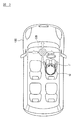
- FIG. 3 is a diagram for explaining a case where the terminal according to the comparative example is used in the interior of the vehicle.
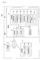
- FIG. 4 is a configuration diagram showing an example of a virtual object display system including a control device for the display device according to the second embodiment.
- FIG. 5 is a flowchart showing a display process of a virtual object executed by the control device of the display device according to the second embodiment.
- FIG. 1 is a configuration diagram showing an example of a virtual object display system including a control device for the display device according to the first embodiment.
- FIG. 2 is a flowchart showing a display process of a virtual object executed by the control device according to the first embodiment.
- FIG. 3 is a diagram for explaining a case where the terminal according to
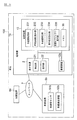
- FIG. 6 is a configuration diagram showing an example of a virtual object display system including a control device for the display device according to the third embodiment.
- FIG. 7 is a flowchart showing a display process of a virtual object executed by the control device of the display device according to the third embodiment.
- FIG. 1 is a configuration diagram showing an example of a virtual object display system including the control device 3 in the present embodiment.
- the system of the present embodiment is a system for displaying a virtual object to a moving occupant.
- a vehicle will be described as an example of the moving body, but the type of the moving body is not limited to the vehicle.
- the system of the present embodiment can be applied to other mobile objects such as bicycles, motorcycles, trains, airplanes, ships, and wheelchairs.
- the terminal 1 of the present embodiment is used indoors of the vehicle 100.
- the subject who uses the terminal 1 is the occupant (human) of the vehicle 100.
- the terminal 1 of the present embodiment has a form that can be worn by an occupant.
- the display device 2 is incorporated in the terminal 1, and the terminal 1 is a device for displaying a virtual object on the display device 2.
- the occupant using the terminal 1 can visually recognize the virtual object displayed on the display device 2 in the interior of the vehicle 100. Details of the virtual object and the display device 2 will be described later.
- Examples of the terminal 1 include a head-mounted display (Head Mounted Display: HMD) that can be attached to the head of an occupant.
- the terminal 1 is also referred to as a wearable terminal.
- FIG. 1 shows one terminal 1
- the number of terminals 1 in the present embodiment is not particularly limited, and the system of the present embodiment may be composed of a plurality of terminals 1. it can.
- the occupant sitting in the driver's seat and the occupant sitting in the passenger seat may each use the terminal 1.
- the configuration of one terminal 1 will be described as an example, but the same configuration can be applied to the other terminals 1 used in the interior of the vehicle 100.
- a virtual object is a two-dimensional model (also referred to as a 2D model, 2D CG, etc.) or a three-dimensional model (also referred to as a 3D model, 3D CG, etc.) arranged in a virtual space or a real space, and refers to a computer. It is an image generated by using. That is, the occupant who uses the terminal 1 can visually recognize the virtual object but cannot touch the virtual object.
- the type and form of the virtual object differ depending on the purpose of the terminal 1.
- the type and form of the virtual object are not particularly limited.
- the virtual object includes both a still image and a moving image.
- the virtual object includes, for example, an image of a real person in addition to a virtual object (for example, an animation character) that does not actually exist.
- the virtual object in addition to the object indicating a person, the virtual object also includes an object of an object such as a guide display board at an intersection.
- the control device 3 described later will be described as an example as a subject for generating the virtual object.
- the vehicle 100 in the present embodiment is a vehicle capable of autonomous driving.
- vehicle 100 any one of two types of automobiles can be used.
- One of the automobiles is an automobile equipped with a navigation device and having a function of automatically controlling driving control (speed control and steering control), and is a human-driven automobile.
- the other vehicle is a vehicle equipped with a navigation device and automatically controlling driving control, and is an unmanned vehicle.
- the vehicle 100 will be described as a vehicle equipped with a navigation device and automatically controlling travel control and driving unmanned.
- An example of a vehicle 100 having such a function is a robot taxi.
- the terminal 1 has a form that can be worn by an occupant (for example, a head-mounted display system).
- a specific example of the terminal 1 is VR goggles.
- VR goggles are a type of head-mounted display.
- VR goggles are devices that can display virtual objects placed in a virtual space and allow the wearer to experience them as if they were real.
- the terminal 1 is not limited to a device or device that can be worn on the face or head of an occupant, and may be a device or device that can be worn on other places.
- the terminal 1 includes a display device 2 and a control device 3. Next, each configuration of the terminal 1 will be described.
- the display device 2 is a device that displays a virtual object to a user (occupant of the vehicle 100) who is wearing the terminal 1.
- the display device 2 is incorporated in the terminal 1, and it is impossible to separate the display device 2 from the terminal 1.
- the display device 2 has a detection unit 21 and a display unit 22.
- the detection unit 21 is a sensor that detects the movement of the head of the occupant wearing the terminal 1.
- Examples of the detection unit 21 include a 9-axis sensor.
- the 9-axis sensor is a motion sensor that detects acceleration (3 axes), angular velocity (3 axes), and geomagnetism (3 axes).
- the detection unit 21 detects the movement of the occupant's head, including changes in speed, acceleration, angular velocity, orientation, and orientation of the occupant's head. ..
- the detection unit 21 detects the front-back, left-right, and up-down accelerations of the occupant's head.
- the acceleration detected by the detection unit 21 is composed of directions indicated by three axes (x-axis, y-axis, z-axis) and numerical values in each direction.
- the acceleration detected by the detection unit 21 will be referred to as the acceleration of the display device 2.
- the acceleration of the display device 2 detected by the detection unit 21 is output to the control device 3.
- the display unit 22 is a part for displaying a virtual object and is a part of the display device 2.
- Examples of the display unit 22 include a display and goggles.
- the specifications of the display and goggles are not particularly limited.
- the display unit 22 uses goggles equipped with a dial function capable of adjusting the focal length, the interpupillary distance, and the like. ..
- Such goggles include a display and a lens for stereoscopic viewing.
- Display information is input to the display device 2 from the control device 3 described later.
- the display device 2 displays the virtual object at an appropriate position on the display unit 22 according to the display information.
- the display information includes information on the display position of the virtual object on the display device 2 and information on the virtual object. Examples of the information on the display position of the virtual object include information on the coordinates of the x-axis, the y-axis, and the z-axis.
- the virtual object information includes information on the space in which the virtual object is placed (for example, information on the real space, information on the virtual space, etc.).
- the control device 3 is composed of a computer equipped with hardware and software, and is accessible to a ROM (Read Only Memory) that stores the program and a CPU (Central Processing Unit) that executes the program stored in the ROM. It is composed of a RAM (Random Access Memory) that functions as a storage device.
- the acceleration acquisition unit 31, acceleration separation unit 32, display position calculation unit 33, and virtual object display unit 34 of the control device 3 shown in FIG. 1 correspond to a CPU, and the memory 35 of FIG. 1 corresponds to a ROM and RAM. ..
- the control device 3 includes an acceleration acquisition unit 31, an acceleration separation unit 32, a display position calculation unit 33, and a virtual object display unit 34, and these blocks are established in the ROM. Each function described later is realized by the software.
- the acceleration acquisition unit 31 acquires the acceleration of the display device 2 detected by the detection unit 21 of the display device 2. As described above, the detection unit 21 detects the front-back, up-down, and left-right accelerations of the occupant's head, respectively. The acceleration acquisition unit 31 acquires acceleration information in each direction from the detection unit 21.
- the acceleration of the display device 2 detected by the detection unit 21 includes the acceleration accompanying the movement of the occupant and the behavior of the vehicle 100. The accompanying acceleration is included.
- Factors that cause acceleration in the display device 2 include not only the movement of the user wearing the terminal 1 but also the environment in which the terminal 1 is used. For example, when the user uses the terminal 1 at home, the head of the user moves due to the movement of the user wearing the terminal 1, and the display device 2 is accelerated. On the other hand, when the terminal 1 is used indoors of the vehicle 100 as in the present embodiment, for example, even if the occupant wearing the terminal 1 is stationary and the occupant does not move his / her head. Due to the behavior of the vehicle 100, the head of the occupant is moved in either direction, and acceleration is generated in the display device 2.
- the behavior of the vehicle 100 includes the behavior caused by the driving operation of the vehicle 100 and the behavior caused by the external environment.
- Examples of the behavior caused by the driving operation of the vehicle 100 include acceleration of the vehicle 100 by the accelerator operation, deceleration of the vehicle 100 by the brake operation, right and left turn of the vehicle 100 by the steering operation, and the like.
- the vehicle 100 accelerates by operating the accelerator.
- a force is applied to the occupant as the vehicle 100 accelerates, and the display device 2 generates acceleration in the traveling direction of the vehicle 100 (also referred to as the front-rear direction of the vehicle 100).
- the vehicle 100 decelerates the vehicle 100 decelerates by operating the brake.
- a force is applied to the occupant due to the deceleration of the vehicle 100, and the display device 2 is accelerated in the traveling direction.
- the direction of the acceleration generated in the display device 2 due to the acceleration of the vehicle 100 and the direction of the acceleration generated in the display device 2 due to the deceleration of the vehicle 100 are opposite to each other. Further, for example, in a scene where the vehicle 100 turns left at an intersection, the vehicle 100 turns left by steering operation. Centrifugal force is applied to the occupant due to the left turn of the vehicle 100, and the display device 2 is accelerated to the right with respect to the traveling direction.
- vibration due to idling can be mentioned. In this case, at least the vertical acceleration of the vehicle 100 is generated in the display device 2.
- a scene in which acceleration is generated in the display device 2 due to the external environment for example, a scene in which the vehicle 100 passes a step on the road surface such as a speed bump can be mentioned. For example, even if the vehicle 100 is traveling at a constant speed without accelerating, when passing through the speed bump, the vehicle 100 moves up and down due to the step of the speed bump. Even in a situation where the occupant is stationary and the acceleration associated with the movement of the occupant is not generated, and the occupant is traveling at a constant speed and the acceleration associated with the driving operation of the vehicle 100 is not generated. A force is applied to the external environment, and acceleration is generated in the display device 2. In the scene of the above example, the display device 2 generates acceleration in the vertical direction of the vehicle 100.
- the acceleration separation unit 32 separates the acceleration of the display device 2 into the acceleration accompanying the movement of the occupant and the acceleration accompanying the behavior of the vehicle 100 by using the information regarding the acceleration of the vehicle 100, and the movement of the occupant is separated from the acceleration of the display device 2. Extract the acceleration that accompanies.
- the acceleration separation unit 32 uses an acceleration separation / extraction model as information regarding the acceleration of the vehicle 100.
- the acceleration separation unit 32 executes a filtering process of the acceleration accompanying the movement of the occupant from the acceleration of the display device 2 by using the acceleration separation / extraction model.
- the acceleration separation / extraction model is a calculation model in which the acceleration of the display device 2 is used as an input value, the acceleration associated with the movement of an occupant, and the acceleration associated with the behavior of the vehicle 100 are used as output values.
- the acceleration separation / extraction model is stored in the memory 35 in advance.
- the acceleration separation unit 32 reads the acceleration separation / extraction model from the memory 35.
- the acceleration separation unit 32 causes the acceleration separation / extraction model to input the acceleration of the display device 2.
- the acceleration separation unit 32 acquires the acceleration associated with the movement of the occupant among the accelerations output from the model.
- the acceleration separation / extraction model is generated by machine learning, for example.
- a plurality of image pickup devices are provided at different locations in the interior of the vehicle 100, and the occupant is imaged from various angles by the image pickup device while the vehicle 100 is traveling.
- the acceleration separation unit 32 executes image processing on each of the plurality of captured images, and calculates the acceleration (x-axis, y-axis, z-axis) accompanying the movement of the occupant.
- a technique such as motion capture is used.
- the acceleration separation unit 32 accumulates acceleration information based on the captured image, analyzes the data, and generates an acceleration separation / extraction model.
- the acceleration based on the captured image is used as reference information when creating the acceleration separation / extraction model.
- a method of calculating the acceleration accompanying the movement of the occupant as it is can be considered by using the motion capture technique without using the acceleration separation / extraction model.
- it is necessary to provide a plurality of imaging devices in the interior of the vehicle 100, and there is a concern that the cost will increase. Therefore, in the present embodiment, it is used as reference information when machine learning the acceleration based on the imaging device.
- the method for generating the acceleration separation / extraction model is an example and is not particularly limited. Further, the method of acquiring the acceleration separation / extraction model is not limited to the acquisition from the memory 35.
- the control device 3 may receive the model from an external server via a communication device (not shown).
- the display position calculation unit 33 calculates the display position of the virtual object in the display device 2 based on the acceleration accompanying the movement of the occupant.
- the acceleration associated with the movement of the occupant is the acceleration extracted from the acceleration of the display device 2 by the acceleration separation unit 32.
- the display position of the virtual object on the display device 2 is a position on the display unit 22 of the display device 2, and is represented by coordinates, for example.
- the display position calculation unit 33 calculates the display position of the virtual object according to the type of the space in which the virtual object is arranged. For example, when displaying a virtual object in the real space, the display position calculation unit 33 calculates the display position of the virtual object with reference to the coordinates in the real space. Further, when the virtual object is displayed in the virtual space, the display position calculation unit 33 calculates the display position of the virtual object with reference to the coordinates in the virtual space.
- the display position calculation unit 33 calculates the display position of the virtual object so that the virtual object is displayed at a fixed position in the virtual space or the real space.
- a certain position in the virtual space or the real space is a position where the occupant can experience the virtual object as if it is fixed at a specific position in the virtual space or the real space. ..
- the display position calculation unit 33 calculates the display position of the virtual object so that the occupant has the virtual object in the passenger seat. In this case, the display position calculation unit 33 calculates the position corresponding to the passenger seat in the display device 2 as the display position of the virtual object.
- the occupant can obtain a feeling that the virtual object exists at a position corresponding to the passenger seat via the terminal 1. Further, when the occupant faces the front of the vehicle 100, the passenger seat disappears from the occupant's field of view, and the virtual object is not displayed on the display device 2.
- the synchronization device 6 is a device for synchronizing the acceleration of the display device 2 with the time axis of the vehicle information detected by the vehicle-mounted sensor group 51.
- the synchronization device 6 is a device capable of communicating with the terminal 1a and the in-vehicle device 5 via the network 7.
- the detection unit 21 of the display device 2 and the vehicle-mounted sensor group 51 are physically separated from each other, and the timing at which the acceleration of the display device 2 is detected by the detection unit 21 and the vehicle-mounted sensor group 51 It is extremely unlikely that the timing at which vehicle information is detected will be synchronized. Therefore, in the present embodiment, a synchronization device 6 is provided in order to synchronize the time axes of the two pieces of information.
- Information on the acceleration of the display device 2 is input from the terminal 1 to the synchronization device 6 via the network 7. Further, vehicle information is input to the synchronization device 6 from the vehicle-mounted device 5 via the network 7.
- the synchronization device 6 has a storage device such as a RAM that temporarily stores each input information. Then, the synchronization device 6 specifies an address capable of synchronizing the time axes of the two pieces of information for each storage device. The synchronization device 6 can synchronize the time axes of the two pieces of information by reading the information input from the address. Then, the synchronization device 6 transmits the acceleration information and the vehicle information of the display device 2 whose time axes are synchronized to the terminal 1a via the network 7.
- the terminal 1a includes a display device 2, a communication device 12, and a control device 13.
- the display device 2 corresponds to the display device 2 according to the first embodiment described above, the above-mentioned description is incorporated for each configuration of the display device 2.
- the acceleration information of the display device 2 detected by the detection unit 21 is output to the communication device 12.
- the communication device 12 is a device capable of communicating with the synchronization device 6 via the network 7.
- the communication device 12 transmits the acceleration information of the display device 2 to the synchronization device 6. Further, the communication device 12 receives the acceleration and vehicle information of the display device 2 whose time axis is synchronized from the synchronization device 6, and outputs the received information to the control device 13.
- Examples of the communication device 12 include a device having a mobile communication function of 4G LTE, a device having a Wifi communication function, a device having a Bluetooth communication function, and the like.
- control device 13 Since the control device 13 has a part of the functions to be realized different from that of the control device 3 according to the first embodiment described above, the above description will be appropriately incorporated for other configurations.
- the control device 13 includes an acceleration acquisition unit 131, a vehicle information acquisition unit 132, a vehicle acceleration calculation unit 133, an acceleration correction unit 134, a display position calculation unit 135, and a virtual object display unit. 136 are included, and these blocks realize each function described later by software established in ROM.
- the acceleration acquisition unit 131 acquires the acceleration of the display device 2 from the synchronization device 6 via the communication device 12.
- the acceleration of the display device 2 is a signal in which the vehicle information and the time axis are synchronized by the synchronization device 6.
- the acceleration of the display device 2 acquired in the present embodiment is the same as the acceleration of the display device 2 acquired by the acceleration acquisition unit 31 according to the first embodiment described above, except that the acceleration is synchronized with the vehicle information. Therefore, as for the explanation of the acceleration of the display device 2, the above-mentioned explanation is appropriately incorporated.
- the vehicle information acquisition unit 132 acquires vehicle information of the vehicle 100 from the synchronization device 6 via the communication device 12.
- the vehicle information of the vehicle 100 is various information detected by the vehicle-mounted sensor group 51, and is a signal in which the acceleration of the display device 2 and the time axis are synchronized by the synchronization device 6. Examples of the vehicle information include the vehicle speed, steering angle, steering operation amount, accelerator operation amount, and brake operation amount of the vehicle 100.
- the vehicle acceleration calculation unit 133 calculates the acceleration of the vehicle 100 based on the vehicle information of the vehicle 100 acquired by the vehicle information acquisition unit 132. For example, a table showing the relationship between each vehicle information and the acceleration of the vehicle is stored in advance in a storage device such as a ROM, and the vehicle acceleration calculation unit 133 refers to the table to correspond to the vehicle information. Identify 100 accelerations. As a result, the vehicle acceleration calculation unit 133 calculates the acceleration of the vehicle 100 based on the vehicle information of the vehicle 100. The acceleration of the vehicle 100 is composed of a direction and a numerical value. Further, the vehicle acceleration calculation unit 133 calculates the acceleration of the vehicle 100 for each direction of the acceleration of the display device 2.
- the technique for calculating the acceleration of the vehicle 100 from various parameters of the vehicle 100 is not limited to the above-mentioned example, and the technique at the time of filing the application of the present application can be appropriately used.
- the acceleration correction unit 134 corrects the acceleration of the display device 2 so as to cancel the acceleration of the vehicle 100, and extracts the acceleration accompanying the movement of the occupant from the acceleration of the display device 2.
- the acceleration of the display device 2 is a predetermined value with respect to the traveling direction of the vehicle 100 (for example, in the positive direction), and the acceleration of the vehicle 100 is in the backward direction (for example, in the negative direction) of the vehicle 100. It is assumed that it is a predetermined value.
- the acceleration correction unit 134 adds the numerical value of the acceleration of the vehicle 100 to the acceleration of the display device 2 in the traveling direction (positive direction) of the vehicle 100. By performing such a calculation, the acceleration in the backward direction (negative direction) of the vehicle 100 included in the acceleration of the display device 2 can be offset, and the acceleration accompanying the movement of the occupant is extracted from the acceleration of the display device 2. be able to.
- the display position calculation unit 135 calculates a position for displaying the virtual object on the display device 2 based on the acceleration accompanying the movement of the occupant.
- the display position calculation unit 135 has the same function as the display position calculation unit 33 according to the first embodiment, except that the acceleration associated with the movement of the occupant is calculated by the acceleration correction unit 134. Therefore, in the present embodiment, the above-mentioned description will be appropriately incorporated.
- the virtual object display unit 136 corresponds to the virtual object display unit 34 according to the first embodiment described above. Therefore, for the explanation of the virtual object display unit 136, the above-mentioned explanation is appropriately incorporated.
- FIG. 5 is a flowchart showing a display process of a virtual object executed by the control device 13 according to the present embodiment.
- the control device 13 repeatedly executes the process shown in FIG. 5 at predetermined cycles. As shown in FIG. 4, it is assumed that the terminal 1a is used in the interior of the vehicle 100.
- step S21 the control device 13 acquires the acceleration of the display device 2 detected by the detection unit 21 of the display device 2.
- the acceleration of the display device 2 is a signal in which the vehicle information of the vehicle 100 and the time axis are synchronized by the synchronization device 6.
- the acceleration of the display device 2 includes an acceleration associated with the movement of the occupant wearing the terminal 1 and an acceleration associated with the behavior of the vehicle 100. Further, the acceleration of the display device 2 includes acceleration in the front-back, left-right, and up-down directions of the display device 2. Further, the acceleration of the display device 2 detected by the detection unit 21 is expressed as an acceleration with time as a variable.
- step S22 the control device 13 executes a process for removing noise with respect to the acceleration of the display device 2 acquired in step S21.
- the control device 13 uses a Kalman filter to remove noise included in the acceleration of the display device 2.
- step S23 the control device 13 acquires vehicle information from the vehicle 100.
- the vehicle information of the vehicle 100 is a signal in which the acceleration of the display device 2 and the time axis are synchronized by the synchronization device 6.
- step S24 the control device 13 executes a process for removing noise from the vehicle information acquired in step S23.
- the control device 13 uses a Kalman filter to remove various noises included in the vehicle information of the vehicle 100.
- step S27 the control device 13 calculates the display position of the virtual object in the display device 2 based on the acceleration accompanying the movement of the occupant extracted in step S26.
- the process of this step corresponds to the process of step S16 in the above-described first embodiment. Therefore, for the explanation of the step, the above-mentioned explanation will be appropriately incorporated.
- step S28 the control device 13 outputs the information related to the display position calculated in step S27 and the information of the virtual object to be displayed at the display position to the display device 2 as display information, and outputs the virtual object to the display device 2. Is displayed.
- step S28 the display process of the virtual object executed by the control device 13 is completed.
- the process of this step corresponds to the process of step S17 in the above-described first embodiment.
- the control device 13 acquires the vehicle information of the vehicle 100 acquired by the in-vehicle sensor group 51 as the information regarding the acceleration of the vehicle 100 from the vehicle 100 via the communication device 12. .. As a result, the control device 13 can calculate the acceleration of the vehicle 100 based on the vehicle information of the vehicle 100. Since it is not necessary to provide the terminal 1 with an acceleration sensor that detects the acceleration of the vehicle 100, the terminal 1 can be made smaller and lighter, and the manufacturing cost of the terminal 1 can be reduced.
- the vehicle information acquired by the control device 13 includes at least one of the speed, steering angle, steering operation amount, accelerator operation amount, and brake operation amount of the vehicle 100.
- the control device 13 can calculate the acceleration of the vehicle 100 in each direction, and as a result, the acceleration accompanying the movement of the occupant can be extracted from the acceleration of the display device 2.
- the control device 13 calculates the acceleration of the vehicle 100 based on the vehicle information of the vehicle 100, and cancels the acceleration of the vehicle 100 with respect to the acceleration of the display device 2 (correction processing). Is executed to extract the acceleration accompanying the movement of the occupant from the acceleration of the display device 2. As a result, the acceleration associated with the movement of the occupant can be extracted from the acceleration of the display device 2. As a result, even if acceleration is generated in the display device 2 due to the behavior of the vehicle 100, the control device 3 can display the virtual object at a fixed position in the virtual space or the real space.
- FIG. 6 is a configuration diagram showing an example of a virtual object display system including the control device 23 according to the third embodiment.
- the system of this embodiment includes a terminal 1b, an in-vehicle device 5b, a synchronization device 6b, and a network 7 constituting a telecommunication network.
- the terminal 1b, the in-vehicle device 5b, and the synchronization device 6b exchange information with each other by wireless communication via the network 7.
- the in-vehicle device 5b is a device mounted on the vehicle 100, and includes an acceleration sensor 51b and an in-vehicle communication device 52b as shown in FIG.
- the acceleration sensor 51b is a sensor that detects the acceleration of the vehicle 100.
- the acceleration of the vehicle 100 is composed of a direction and a numerical value.
- the acceleration information of the vehicle 100 detected by the acceleration sensor 51b is output to the in-vehicle communication device 52b.
- the in-vehicle communication device 52b is a device capable of communicating with the synchronization device 6b via the network 7.
- the in-vehicle communication device 52b transmits the acceleration information of the vehicle 100 input from the acceleration sensor 51b to the synchronization device 6.
- the same equipment as the in-vehicle communication device 52 according to the second embodiment described above can be applied to the in-vehicle communication device 52b.
- the synchronization device 6b is a device for synchronizing the acceleration of the display device 2 with the time axis of the acceleration of the vehicle 100 detected by the acceleration sensor 51b.
- the synchronization device 6b is a device capable of communicating with the terminal 1b and the in-vehicle device 5b via the network 7.
- the same equipment as the synchronization device 6 according to the second embodiment described above can be applied to the synchronization device 6b. Therefore, as for the specific description of the synchronization device 6b, the above-mentioned description is appropriately incorporated.
- the synchronization device 6 transmits information on the acceleration of the display device 2 and the acceleration of the vehicle 100 whose time axes are synchronized to the terminal 1b via the network 7.
- the terminal 1b includes a display device 2, a communication device 12b, and a control device 23. Since the display device 2 has the same function as the display device 2 according to the second embodiment described above, the above description is incorporated for each configuration of the display device 2.
- the communication device 12b is a device capable of communicating with the synchronization device 6b via the network 7.
- the communication device 12b transmits the acceleration information of the display device 2 output from the display device 2 to the synchronization device 6b. Further, the communication device 12b receives information on the acceleration of the display device 2 and the acceleration of the vehicle 100 whose time axes are synchronized from the synchronization device 6b, and outputs the received information to the control device 13.
- the same equipment as the communication device 12 according to the second embodiment described above can be applied to the communication device 12b.
- control device 23 Since the control device 23 is partially different in the functions to be realized as compared with the control device 3 according to the first embodiment and the control device 13 according to the second embodiment described above, the other configurations are described above. Use the explanation as appropriate.
- the control device 23 includes an acceleration acquisition unit 231, a vehicle acceleration acquisition unit 232, an acceleration correction unit 233, a display position calculation unit 234, and a virtual object display unit 235.
- the block realizes each function described later by the software established in the ROM.
- the acceleration acquisition unit 231 corresponds to the acceleration acquisition unit 131 according to the second embodiment described above. Therefore, for the explanation of the function of the acceleration acquisition unit 231, the above-mentioned explanation is appropriately incorporated.
- the vehicle acceleration acquisition unit 232 acquires the acceleration information of the vehicle 100 from the synchronization device 6b via the communication device 12b.
- the acceleration of the vehicle 100 is a signal in which the acceleration of the display device 2 and the time axis are synchronized by the synchronization device 6b.
- the acceleration correction unit 233, the display position calculation unit 234, and the virtual object display unit 235 correspond to the acceleration correction unit 134, the display position calculation unit 135, and the virtual object display unit 136, respectively, according to the second embodiment. Therefore, for the explanation of each function, the above-mentioned explanation is appropriately incorporated.
- FIG. 7 is a flowchart showing a display process of a virtual object executed by the control device 23 according to the present embodiment.
- the control device 23 repeatedly executes the process shown in FIG. 7 at predetermined cycles. As shown in FIG. 6, it is assumed that the terminal 1b is used in the interior of the vehicle 100.
- step S31 the control device 23 acquires the acceleration of the display device 2 from the detection unit 21 of the display device 2.
- the acceleration of the display device 2 is a signal in which the acceleration of the vehicle 100 and the time axis are synchronized by the synchronization device 6b.
- the acceleration of the display device 2 includes an acceleration associated with the movement of the occupant wearing the terminal 1b and an acceleration associated with the behavior of the vehicle 100. Further, the acceleration of the display device 2 includes acceleration in the front-back, left-right, and up-down directions of the display device 2. Further, the acceleration of the display device 2 detected by the detection unit 21 is expressed as an acceleration with time as a variable.
- step S32 the control device 23 executes a process for removing noise with respect to the acceleration of the display device 2 acquired in step S31.
- the control device 23 uses a Kalman filter to remove noise included in the acceleration of the display device 2.
- the synchronization device 6 (6b) has been described as a configuration different from that of the vehicle 100 and the terminal 1a (1b), but the synchronization device 6 (6b) is described. It may be incorporated in the terminal 1a (1b). That is, the terminal 1a (1b) may include the synchronization device 6 (6b).
Landscapes
- Engineering & Computer Science (AREA)
- Physics & Mathematics (AREA)
- General Physics & Mathematics (AREA)
- Theoretical Computer Science (AREA)
- Computer Hardware Design (AREA)
- Computer Graphics (AREA)
- Controls And Circuits For Display Device (AREA)
- User Interface Of Digital Computer (AREA)
Abstract
移動体(100)の乗員が装着可能であり、乗員に仮想オブジェクトを表示する表 示装置(2)の制御装置(3)であって、表示装置(2)に含まれる検出部(21) から、表示装置(2)の加速度を取得する加速度取得部(31)と、表示装置(2) を制御する表示制御部(32~34)と、を備え、表示制御部(32~34)は、移 動体(100)の加速度に関する情報を用いて、表示装置(2)の加速度から乗員の 動きに伴う加速度を抽出し、乗員の動きに伴う加速度に基づいて、表示装置(2)に おける仮想オブジェクトの表示位置を算出し、表示位置(2)に仮想オブジェクトを 表示させる制御装置(3)。
Description
本発明は、表示装置の制御装置、端末機、プログラム、コンピュータ読み取り可能な記録媒体、及び表示装置の制御方法に関するものである。
ユーザが装着可能であり、当該ユーザに仮想オブジェクトを表示する表示装置が知られている。この種の表示装置には、表示装置の加速度を検出するセンサが含まれている。表示装置は、センサにより検出された表示装置の加速度に基づいて、表示装置における表示位置を算出する。そして、表示装置は、算出した表示位置に仮想オブジェクトを表示することで、ユーザの動きに関わらず、仮想空間内又は実空間内の一定の位置に仮想オブジェクトを表示させる。
上記の表示装置が移動体内で使用される場合、表示装置に加速度が生じる要因は、乗員の動きに加えて移動体の挙動も含まれるため、上記のセンサでは乗員の動きの伴う加速度を適切に検出することができない。このため、表示装置が移動体内で使用される場合には、仮想空間内又は実空間内の一定の位置に仮想オブジェクトを表示させることができない、という問題がある。
本発明が解決しようとする課題は、仮想オブジェクトの表示装置が移動体内で使用される場合に、移動体の挙動に関わらず、仮想空間内又は実空間内の一定の位置に仮想オブジェクトを表示させることが可能な表示装置の制御装置、端末機、及び表示装置の制御方法を提供することである。
本発明は、仮想オブジェクトを表示する表示装置に含まれる検出部から、表示装置の加速度を取得し、移動体の加速度に関する情報を用いて、表示装置の加速度から乗員の動きに伴う加速度を抽出し、乗員の動きに伴う加速度に基づいて、表示装置における仮想オブジェクトの表示位置を算出し、算出した表示位置に仮想オブジェクトを表示させることで、上記課題を解決する。
本発明によれば、移動体の挙動に関わらず、仮想空間内又は実空間内の一定の位置に仮想オブジェクトを表示させることができる。
以下、本発明の実施形態を図面に基づいて説明する。
《第1実施形態》
図1は、本実施形態における制御装置3を含む仮想オブジェクト表示システムの一例を示す構成図である。本実施形態のシステムは、移動体の乗員に対して仮想オブジェクトを表示するためのシステムである。本実施形態では、移動体として、車両を例に挙げて説明するが、移動体の種別は車両に限られない。例えば、本実施形態のシステムは、自転車、バイク、電車、飛行機、船、車椅子等のその他の移動体においても適用することができる。
図1は、本実施形態における制御装置3を含む仮想オブジェクト表示システムの一例を示す構成図である。本実施形態のシステムは、移動体の乗員に対して仮想オブジェクトを表示するためのシステムである。本実施形態では、移動体として、車両を例に挙げて説明するが、移動体の種別は車両に限られない。例えば、本実施形態のシステムは、自転車、バイク、電車、飛行機、船、車椅子等のその他の移動体においても適用することができる。
図1に示すように、本実施形態の端末機1は、車両100の室内で使用される。端末機1を使用する主体は、車両100の乗員(人間)である。本実施形態の端末機1は、乗員に装着可能な形態を有している。また、表示装置2は端末機1に組み込まれており、端末機1は表示装置2に仮想オブジェクトを表示させる機器である。これにより、端末機1を使用する乗員は、車両100の室内において、表示装置2に表示される仮想オブジェクトを視認することができる。仮想オブジェクト及び表示装置2の詳細については後述する。端末機1としては、乗員の頭部に装着可能なヘッドマウントディスプレイ(Head Mounted Display:HMD)が挙げられる。端末機1は、ウェアラブル端末とも称される。
また、図1では、1台の端末機1を示しているが、本実施形態において端末機1の台数は特に限定されず、本実施形態のシステムは、複数の端末機1で構成することもできる。例えば、運転座席に座る乗員及び助手席に座る乗員が端末機1をそれぞれ使用していてもよい。以降の説明では、一台の端末機1の構成を例に挙げて説明するが、車両100の室内で使用されるその他の端末機1についても同様の構成を適用することができる。
ここで、仮想オブジェクトについて説明する。仮想オブジェクトとは、仮想空間内又は実空間内に配置された2次元モデル(2Dモデル、2D CG等ともいう)、又は3次元モデル(3Dモデル、3D CG等ともいう)であって、コンピュータを用いて生成された画像である。すなわち、端末機1を使用する乗員は、仮想オブジェクトを視認することはできるが、仮想オブジェクトには触れることはできない。
仮想オブジェクトの種別及び形態は、端末機1の用途によって異なっている。本実施形態では、仮想オブジェクトの種別及び形態は特に限定されない。例えば、仮想オブジェクトには、静止画、動画の何れも含まれる。また、仮想オブジェクトには、実際には存在しない仮想のオブジェクト(例えば、アニメのキャラクター等)に加えて、例えば、実在の人物を撮影した映像も含まれる。また、仮想オブジェクトには、人物を示すオブジェクトに加えて、例えば、交差点の案内表示板等、物のオブジェクトも含まれる。本実施形態では、仮想オブジェクトを生成する主体として後述する制御装置3を例に挙げて説明する。
次に、図1を用いながら、本実施形態のシステムの各構成について説明する。まず、車両100について説明する。本実施形態における車両100は、自律走行が可能な車両である。車両100は、2種類の自動車のいずれかを用いることができる。一方の自動車は、ナビゲーション装置が搭載されているとともに走行制御(速度制御と操舵制御)を自動制御する機能を備える自動車であって、人間が運転する自動車である。他方の自動車は、ナビゲーション装置が搭載されているとともに走行制御を自動制御する自動車であって、無人で運転する自動車である。本実施形態では、車両100をナビゲーション装置が搭載されているとともに走行制御を自動制御する自動車であって無人で運転する自動車として説明する。このような機能を有する車両100の一例として、ロボットタクシーが挙げられる。
次に、端末機1について説明する。端末機1は、上述のとおり、乗員に装着可能な形態(例えば、ヘッドマウントディスプレイ方式)を有している。端末機1の具体例としては、VRゴーグルが挙げられる。VRゴーグルは、ヘッドマウントディスプレイの一種である。VRゴーグルは、仮想空間内に配置された仮想オブジェクトを表示して、装着者にあたかも現実のように体験させることが可能な機器である。なお、端末機1は、乗員の顔や頭部に装着可能な形態の装置又は機器に限られず、その他の箇所に装着可能な形態の装置又は機器であってもよい。
図1に示すように、端末機1は、表示装置2と、制御装置3とを備えている。次に、端末機1の各構成について説明する。
表示装置2は、端末機1を装着しているユーザ(車両100の乗員)に対して、仮想オブジェクトを表示する装置である。本実施形態では、表示装置2は、端末機1に組み込まれており、表示装置2を端末機1から分離することは不可能なものとする。表示装置2は、検出部21と表示部22を有している。
検出部21は、端末機1を装着している乗員の頭部の動きを検出するセンサである。検出部21としては、例えば、9軸センサが挙げられる。9軸センサは、加速度(3軸)、角速度(3軸)、地磁気(3軸)を検出するモーションセンサである。例えば、端末機1が乗員の頭部に装着されているときには、検出部21は、乗員の頭部の速度、加速度、角速度、向き、向きの変化を含む、乗員の頭部の動きを検出する。これにより、検出部21は、乗員の頭部の前後、左右、及び上下の加速度等を検出する。検出部21により検出された加速度は、3軸(x軸、y軸、z軸)で示す方向と、それぞれの方向における数値から構成されている。以降では、検出部21により検出された加速度を、表示装置2の加速度と称して説明する。検出部21により検出された表示装置2の加速度は、制御装置3に出力される。
表示部22は、仮想オブジェクトを表示するための部位であって、表示装置2の一部である。表示部22としては、例えば、ディスプレイ、ゴーグルなどが挙げられる。ディスプレイやゴーグルの仕様は特に限定されるものではなく、例えば、端末機1がVRゴーグルの場合、表示部22としては、焦点距離、瞳孔間距離等を調整できるダイヤル機能を搭載したゴーグルが用いられる。このようなゴーグルは、ディスプレイと、立体視のためのレンズを含んでいる。
表示装置2には、後述する制御装置3から、表示情報が入力される。表示装置2は、表示情報に従って、表示部22における適切な位置に仮想オブジェクトを表示する。表示情報には、表示装置2における仮想オブジェクトの表示位置の情報と、仮想オブジェクトの情報が含まれている。仮想オブジェクトの表示位置の情報としては、例えば、x軸、y軸、及びz軸の座標の情報が挙げられる。また、仮想オブジェクトの情報には、仮想オブジェクトの種別に加えて、仮想オブジェクトを配置する空間の情報(例えば、実空間の情報、仮想空間の情報など)が含まれる。表示装置2が表示部22における適切な仮想オブジェクトを表示すことで、端末機1を装着している乗員は、仮想空間又は実空間内に配置された仮想オブジェクトを視認することができる。
次に、制御装置3について説明する。制御装置3は、ハードウェア及びソフトウェアを備えたコンピュータにより構成され、プログラムを格納したROM(Read Only Memory)と、このROMに格納されたプログラムを実行するCPU(Central Processing Unit)と、アクセス可能な記憶装置として機能するRAM(Random Access Memory)とから構成されている。図1に示す制御装置3の加速度取得部31、加速度分離部32、表示位置算出部33、及び仮想オブジェクト表示部34はCPUに相当し、また図1のメモリ35は、ROM及びRAMに相当する。
図1に示すように、制御装置3には、加速度取得部31と、加速度分離部32と、表示位置算出部33と、仮想オブジェクト表示部34が含まれ、これらのブロックは、ROMに確立されたソフトウェアによって、後述する各機能を実現する。
加速度取得部31の機能について説明する。加速度取得部31は、表示装置2の検出部21により検出された、表示装置2の加速度を取得する。上述のとおり、検出部21は、乗員の頭部の前後、上下、左右の加速度をそれぞれ検出する。加速度取得部31は、検出部21から、各方向の加速度の情報を取得する。本実施形態のように、端末機1を車両100の室内で使用する場合には、検出部21により検出された表示装置2の加速度には、乗員の動きに伴う加速度と、車両100の挙動に伴う加速度が含まれている。
ここで、表示装置2に加速度が発生する要因について説明する。表示装置2に加速度が発生する要因には、端末機1を装着したユーザの動きだけでなく、端末機1を使用する環境も含まれる。例えば、ユーザが自宅で端末機1を使用した場合、端末機1を装着したユーザの動きに起因して、ユーザの頭部が動き、表示装置2には加速度が発生する。これに対して、本実施形態のように、端末機1を車両100の室内で使用した場合、例えば、端末機1を装着した乗員が静止しており、乗員が頭部を動かさなくても、車両100の挙動により、乗員の頭部がいずれかの方向に動かされ、表示装置2には加速度が発生する。
車両100の挙動には、車両100の運転操作に起因した挙動と、外部環境に起因した挙動が含まれる。車両100の運転操作に起因した挙動としては、例えば、アクセル操作による車両100の加速、ブレーキ操作による車両100の減速、ステアリング操作による車両100の右左折などが挙げられる。例えば、車両100が停止状態から発進する場面では、車両100はアクセル操作により加速する。乗員には車両100の加速に伴う力がかかり、表示装置2には車両100の進行方向(車両100の前後方向ともいう)に加速度が発生する。また、例えば、車両100が減速する場面では、車両100はブレーキ操作により減速する。乗員には車両100の減速に伴う力がかかり、表示装置2には進行方向に加速度が発生する。車両100の加速により表示装置2に発生する加速度の向きと、車両100の減速により表示装置2に発生する加速度の向きは互いに反対方向となる。また、例えば、車両100が交差点を左折する場面では、車両100はステアリング操作により左折する。乗員には車両100の左折に伴う遠心力がかかり、表示装置2には進行方向に対して右方向の加速度が発生する。なお、車両100の運転操作に起因した挙動の他の例としては、アイドリングによる振動が挙げられる。この場合、表示装置2には、少なくとも車両100の上下方向の加速度が発生する。
また、外部環境に起因して表示装置2に加速度が発生する場面としては、例えば、車両100がスピードバンプなどの路面上にある段差を通過する場面が挙げられる。例えば、車両100が加速せずに一定速度で走行していても、スピードバンプを通過する際には、車両100はスピードバンプの段差により上下動する。乗員が静止していることにより乗員の動きに伴う加速度が発生しておらず、かつ、一定速度の走行により車両100の運転操作に伴う加速度が発生していない状況であっても、乗員には外部環境により力がかかり、表示装置2には加速度が発生する。上記例の場面では、表示装置2には、車両100の上下方向の加速度が発生する。
次に、加速度分離部32の機能について説明する。加速度分離部32は、車両100の加速度に関する情報を用いて、表示装置2の加速度を、乗員の動きに伴う加速度と車両100の挙動に伴う加速度に分離し、表示装置2の加速度から乗員の動きに伴う加速度を抽出する。例えば、加速度分離部32は、車両100の加速度に関する情報として加速度分離・抽出モデルを使用する。加速度分離部32は、加速度分離・抽出モデルを使用して、表示装置2の加速度から、乗員の動きに伴う加速度のフィルタリング処理を実行する。
加速度分離・抽出モデルとは、表示装置2の加速度を入力値、乗員の動きに伴う加速度及び車両100の挙動に伴う加速度を出力値とする計算用のモデルである。例えば、加速度分離・抽出モデルは、予めメモリ35に格納されている。加速度分離部32は、表示装置2の加速度が加速度取得部31により取得されると、メモリ35から加速度分離・抽出モデルを読み出する。そして、加速度分離部32は、加速度分離・抽出モデルに表示装置2の加速度を入力させる。そして、加速度分離部32は、当該モデルから出力された加速度のうち乗員の動きに伴う加速度を取得する。
加速度分離・抽出モデルは、例えば、機械学習により生成される。例えば、車両100の室内の異なる箇所に複数の撮像装置を設け、車両100が走行している状態で、乗員を撮像装置で様々な角度から撮像する。加速度分離部32は、複数の撮像画像それぞれに対して画像処理を実行し、乗員の動きに伴う加速度(x軸、y軸、z軸)を算出する。撮像画像に基づいて加速度を算出する際には、例えば、モーションキャプチャなどの技術が用いられる。
加速度分離部32は、撮像画像に基づく加速度の情報を蓄積させて、データ解析を行い、加速度分離・抽出モデル生成する。撮像画像を用いて加速度を算出する場合、センサなどの計測器を用いて加速度を算出する場合と比べて、乗員の動きに連動した加速度を算出することができる。このため、本実施形態では、撮像画像に基づく加速度を、加速度分離・抽出モデルを作成する際の参照情報として用いている。なお、本実施形態とは異なり、加速度分離・抽出モデルを用いずに、モーションキャプチャの技術を用いて、乗員の動きに伴う加速度をそのまま算出する方法も考えられる。しかし、この場合、車両100の室内に複数の撮像装置を設ける必要があり、コストが高くなる点が懸念される。そこで、本実施形態では、撮像装置に基づく加速度を機械学習させる際の参照情報として用いている。
なお、加速度分離・抽出モデルの生成方法は、一例であって特に限定されるものではない。また、加速度分離・抽出モデルを取得する方法は、メモリ35からの取得に限られない。例えば、制御装置3は、通信装置(図示していない)を介して、外部のサーバから当該モデルを受信してもよい。
次に、表示位置算出部33の機能について説明する。表示位置算出部33は、乗員の動きに伴う加速度に基づいて、表示装置2における仮想オブジェクトの表示位置を算出する。乗員の動きに伴う加速度は、加速度分離部32により、表示装置2の加速度から抽出された加速度である。表示装置2における仮想オブジェクトの表示位置とは、表示装置2の表示部22での位置であり、例えば、座標で表される。
また、表示位置算出部33は、仮想オブジェクトが配置される空間の種別に応じて、仮想オブジェクトの表示位置を算出する。例えば、表示位置算出部33は、実空間内に仮想オブジェクトを表示する場合には、実空間での座標を基準にして、仮想オブジェクトの表示位置を算出する。また、表示位置算出部33は、仮想空間内に仮想オブジェクトを表示する場合には、仮想空間での座標を基準にして、仮想オブジェクトの表示位置を算出する。
また、表示位置算出部33は、仮想空間内又は実空間内の一定の位置に仮想オブジェクトが表示されるように、仮想オブジェクトの表示位置を算出する。仮想空間内又は実空間内の一定の位置とは、乗員があたかも仮想オブジェクトが仮想空間内又は実空間の内特定の位置に固定されているかのように乗員に体感することが可能な位置である。例えば、運転席に座る乗員が端末機1を装着している場合、表示位置算出部33は、当該乗員にあたかも助手席に仮想オブジェクトが存在するように、仮想オブジェクトの表示位置を算出する。この場合、表示位置算出部33は、表示装置2において助手席に対応する位置を、仮想オブジェクトの表示位置として算出する。これにより、上記の乗員が助手席を向いた際には、この乗員は、端末機1を介して、助手席に対応する位置に仮想オブジェクトが存在するような感覚を得ることができる。また、乗員が車両100の前方を向いた際には、乗員の視界からは助手席が消え、表示装置2には当該仮想オブジェクトが表示されない。
次に、仮想オブジェクト表示部34の機能について説明する。仮想オブジェクト表示部34は、所定の仮想オブジェクトを、表示位置算出部33により算出された特定の位置に表示するよう、表示装置2を制御する。例えば、仮想オブジェクト表示部34は、表示する仮想オブジェクトの内容を示す情報と当該仮想オブジェクトの表示位置とが関連付けられた情報を表示情報として表示装置2に出力する。
仮想オブジェクトの内容、及び仮想オブジェクトが配置される空間は、端末機1の用途に応じて異なっている。例えば、車両100の走行経路を案内するためのアプリケーションが端末機1にインストールされている場合、仮想オブジェクトとしては、前方の交差点の情報を示すオブジェクト、走行経路を音声で案内するキャラクターのオブジェクトなどが例示できる。また、この場合、仮想オブジェクトが表示される空間は、実空間となる。仮想オブジェクト表示部34には、仮想オブジェクトを実空間(乗員が端末機1を介して視認できる現実の世界)に配置して、ユーザに現実が拡張したように体験させる拡張現実(Augment Reality:AR)の技術が用いられる。
なお、上記仮想オブジェクト表示部34の説明では、拡張現実の技術を用いて説明したが、仮想オブジェクト表示部34は、ユーザにあたかも現実のように体験させる仮想現実(Virtual Reality:VR)の技術を用いて、仮想オブジェクトを仮想空間(コンピュータにより生成された仮想的な世界)に配置してもよい。本実施形態では、VR又はARの技術について、本願出願時における技術を適宜援用できる。
次に、図2を用いて、本実施形態に係る制御装置3が実行する仮想オブジェクトの表示処理について説明する。図2は、本実施形態に係る制御装置3が実行する仮想オブジェクトの表示処理を示すフローチャートである。制御装置3は、所定の周期ごとに図2に示す処理を繰り返し実行する。なお、端末機1は、図1に示すように、車両100の室内で用いられているものとする。
ステップS11では、制御装置3は、表示装置2の検出部21から、表示装置2の加速度を取得する。表示装置2の加速度には、端末機1を装着した乗員の動きに伴う加速度と、車両100の挙動に伴う加速度が含まれている。また、表示装置2の加速度には、表示装置2の前後、左右、及び上下方向の加速度が含まれている。また、検出部21により検出された表示装置2の加速度は、時間を変数とした加速度として表される。
ステップS12では、制御装置3は、ステップS11で取得した表示装置2の加速度に対して、ノイズを除去するための処理を実行する。例えば、制御装置3は、カルマンフィルタを用いて、表示装置2の加速度に含まれるノイズを除去する。
ステップS13では、制御装置3は、ステップS12でノイズ除去された表示装置2の加速度に対して、時間−周波数解析を実行する。例えば、制御装置3は、短時間フーリエ変換(Short−Time Fourier Transform:STF)や、離散フーリエ変換(Discrete Fourier Transform:DFT)により、時間を変数とした表示装置2の加速度を、周波数を変数とした表示装置2の加速度に変換する。例えば、ステップS13の処理後の表示装置2の加速度は、周波数スペクトルとして表される。
ステップS14では、制御装置3は、加速度分離・抽出モデルを用いて、ステップS13で変換した表示装置2の加速度から、乗員の動きに伴う加速度と車両100の挙動に伴う加速度を分離し、乗員の動きに伴う加速度を抽出する。例えば、加速度分離・抽出モデルは、メモリ35に予め記憶されているモデルであって、機械学習により生成されたモデルである。なお、このステップで抽出された乗員の動きに伴う加速度は、周波数を変数とした加速度として表される。
ステップS15では、制御装置3は、ステップS14で抽出された乗員の動きに伴う加速度に対して、逆フーリエ変換を実行して、乗員の動きに伴う加速度を周波数スペクトルから時間を変数とした信号に再構成する。ステップS15の処理の後の乗員の動きに伴う加速度は、時間を変数とした加速度として表される。
ステップS16では、制御装置3は、ステップS15で再構成された乗員の動きに伴う加速度に基づいて、表示装置2における仮想オブジェクトの表示位置を算出する。制御装置3は、仮想オブジェクトを配置する空間の種別に応じて、仮想オブジェクトの表示位置を算出する。また、制御装置3は、仮想オブジェクトが仮想空間内又は実空間内の一定の位置に表示されるように、仮想オブジェクトの表示位置を算出する。なお、仮想オブジェクトが複数存在する場合には、制御装置3は、仮想オブジェクトごとに、仮想オブジェクトの表示位置を算出する。
ステップS17では、制御装置3は、ステップS16で算出した表示位置と、当該表示位置に表示する仮想オブジェクトの情報が関連付いた情報を表示情報として表示装置2に出力し、表示装置2に仮想オブジェクトを表示させる。ステップS17での処理が終了すると、制御装置3が実行する仮想オブジェクトの表示処理は終了する。
次に、図3を用いて、本実施形態の端末機1を用いることにより奏する作用・効果について説明する。図3は、車両100の室内で比較例に係る端末機1’が用いられた場合を説明するための図である。車両100の運転席には、比較例に係る端末機1’を装着した乗員Uが運転席で静止しており、車両100は自律走行により走行しているものとする。図3は、当該場面での車両100の平面図である。なお、図3では、説明の便宜上、車両100の室内を示している。
比較例に係る端末機1’は、本実施形態の端末機1と比べて、制御装置3に加速度分離部32を備えていないことを除いて、本実施形態の端末機1と同様の構成を有しているものとする。すなわち、比較例に係る端末機1’の制御装置は、表示装置の加速度に基づいて、表示装置における仮想オブジェクトOBの表示位置を算出し、当該表示位置に仮想オブジェクトOBを表示させる。これにより、図3に示す例において、比較例に係る端末機1’を装着した乗員Uは、あたかもステアリングの進行方向左側に仮想オブジェクトOBが位置するように感じている。
しかしながら、車両100が自律走行により走行すると、車両100の挙動に起因して、比較例に係る表示装置には所定方向に加速度が発生する。そして、比較例に係る制御装置は、発生した加速度に基づいて、表示装置における仮想オブジェクトの表示位置を算出し、当該表示位置に仮想オブジェクトOBを表示させる。そのため、図3に示すように、乗員U自身は車両100の室内で静止していても、車両100の挙動に伴って、仮想オブジェクトOBの表示位置は車両100の前後及び左右方向に移動してしまう。これは、比較例に係る端末機1’では、仮想空間内又は実空間内の一定の位置に仮想オブジェクトOBを表示させようと制御しているにも関わらず、表示装置2に加速度が発生する要因として、端末機の装着者の動きしか想定していないためである。
これに対して、本実施形態に係る表示装置2の制御装置3は、表示装置2に含まれる検出部21から、表示装置2の加速度を取得し、車両100の加速度に関する情報として加速度分離・抽出モデルを用いて、表示装置2の加速度から乗員の動きに伴う加速度を抽出する。そして、制御装置3は、抽出した乗員の動きに伴う加速度に基づいて、表示装置2における仮想オブジェクトの表示位置を算出し、算出した表示位置に仮想オブジェクトを表示させる。これにより、例えば、車両100の挙動に伴って表示装置2に加速度が発生しても、制御装置3は、仮想空間内又は実空間内の一定の位置に仮想オブジェクトを表示させることができる。言い換えると、車両100の挙動に関わらず、仮想空間内又は実空間内の一定の位置に仮想オブジェクトを表示させることができる。その結果、乗員が車両100の室内で端末機1を介して仮想オブジェクトを見ていても、乗員に仮想オブジェクトが移動する等の違和感を与えることを防ぐことができる。車両100の室内において、仮想オブジェクトを表示する端末機1を使用することができる。
図3の例において、比較例に係る端末機1’に代えて、本実施形態に係る端末機1を用いた場合について説明する。本実施形態に係る端末機1では、車両100の挙動に伴って表示装置2に加速度が発生しても、制御装置3は、仮想空間内又は実空間内の一定の位置に仮想オブジェクトを表示させることができる。これにより、端末機1を装着した乗員Uに、あたかもステアリングの進行方向左側に仮想オブジェクトOBが固定されているかのように感じさせることができる。
≪第2実施形態≫
次に、第2実施形態に係る制御装置13を含む端末機1aについて説明する。図4は、第2実施形態に係る制御装置13を含む仮想オブジェクト表示システムの一例を示す構成図である
次に、第2実施形態に係る制御装置13を含む端末機1aについて説明する。図4は、第2実施形態に係る制御装置13を含む仮想オブジェクト表示システムの一例を示す構成図である
本実施形態のシステムは、端末機1aと、車載装置5と、同期装置6と、電気通信回線網を構成するネットワーク7とを含む。端末機1a、車載装置5、及び同期装置6は、ネットワーク7を介した無線通信により互いに情報を授受する。
車載装置5は、車両100に搭載された装置であり、図4に示すように、車載センサ群51と、車載通信装置52とを含む。
車載センサ群51は、車両100の走行状態を検出するための各種センサである。車載センサ群51としては、例えば、車速センサ、操舵角センサ、ステアリング操作センサ、アクセル操作センサ、ブレーキ操作センサ等が挙げられる。車載センサ群51は、車両100の車速、操舵角、ステアリング操作量、アクセル操作量、及びブレーキ操作量のうち少なくともいずれか一つを検出する。車載センサ群51により検出された一又は複数の情報は、車両情報として車載通信装置52に出力される。なお、本実施形態において、車載センサ群51には車両100の加速度を検出する加速度センサは含まれていないものとする。
車載通信装置52は、ネットワーク7を介して、同期装置6と通信可能な機器である。車載通信装置52は、車載センサ群51から入力される車両情報を同期装置6に送信する。車載通信装置52としては、4G LTEのモバイル通信機能を備えたデバイス、Wifi通信機能を備えたデバイス、Bluetooth(登録商標)通信機能を備えたデバイス等が例示できる。
同期装置6は、表示装置2の加速度と車載センサ群51により検出された車両情報の時間軸を同期させるための装置である。同期装置6は、ネットワーク7を介して、端末機1a及び車載装置5と通信可能な機器である。一般的に、表示装置2の検出部21と、車載センサ群51とは物理的に離れた場所に位置し、検出部21により表示装置2の加速度が検出されたタイミングと、車載センサ群51に車両情報が検出されたタイミングが同期する可能性は極めて低い。そのため、本実施形態では、2つの情報の時間軸を同期させるために、同期装置6を設けている。
同期装置6には、端末機1から、ネットワーク7を介して表示装置2の加速度の情報が入力される。また、同期装置6には、車載装置5から、ネットワーク7を介して車両情報が入力される。例えば、同期装置6は、入力された各情報を一時的に記憶させるRAM等の記憶装置を有している。そして、同期装置6は、各記憶装置について、2つの情報の時間軸を同期させることが可能なアドレスを特定する。同期装置6は、当該アドレスから入力された情報を読み出すことで、2つの情報の時間軸を同期させることができる。そして、同期装置6は、ネットワーク7を介して、時間軸が同期した表示装置2の加速度の情報及び車両情報を、端末機1aに送信する。
本実施形態に係る端末機1aは、表示装置2と、通信装置12と、制御装置13を備えている。
表示装置2は、上述した第1実施形態に係る表示装置2に対応しているため、表示装置2の各構成については、既述の説明を援用する。なお、本実施形態では、第1実施形態と異なり、検出部21により検出された表示装置2の加速度の情報は、通信装置12に出力される。
通信装置12は、ネットワーク7を介して、同期装置6と通信可能な機器である。通信装置12は、表示装置2の加速度の情報を同期装置6に送信する。また、通信装置12は、同期装置6から時間軸が同期した表示装置2の加速度及び車両情報を受信し、受信した情報を制御装置13に出力する。通信装置12としては、4G LTEのモバイル通信機能を備えたデバイス、Wifi通信機能を備えたデバイス、Bluetooth通信機能を備えたデバイス等が例示できる。
制御装置13は、上述した第1実施形態に係る制御装置3と比べて、実現する機能の一部が異なるため、それ以外の構成については、既述の説明を適宜援用する。
図4に示すように、制御装置13には、加速度取得部131と、車両情報取得部132と、車両加速度算出部133と、加速度補正部134と、表示位置算出部135と、仮想オブジェクト表示部136が含まれ、これらのブロックは、ROMに確立されたソフトウェアによって、後述する各機能を実現する。
加速度取得部131の機能について説明する。加速度取得部131は、通信装置12を介して、同期装置6から表示装置2の加速度を取得する。表示装置2の加速度は、同期装置6によって車両情報と時間軸が同期した信号である。なお、本実施形態において取得した表示装置2の加速度は、上述した第1実施形態に係る加速度取得部31が取得した表示装置2の加速度と比べて、車両情報に同期している点以外は同じであるため、表示装置2の加速度の説明については、既述の説明を適宜援用する。
次に、車両情報取得部132の機能について説明する。車両情報取得部132は、通信装置12を介して、同期装置6から車両100の車両情報を取得する。車両100の車両情報とは、車載センサ群51により検出された各種情報であって、同期装置6によって表示装置2の加速度と時間軸が同期した信号である。車両情報としては、例えば、車両100の車速、操舵角、ステアリング操作量、アクセル操作量、ブレーキ操作量が挙げられる。
次に、車両加速度算出部133の機能について説明する。車両加速度算出部133は、車両情報取得部132により取得した、車両100の車両情報に基づいて、車両100の加速度を算出する。例えば、各車両情報と車両の加速度との関係性を示すテーブルが予めROM等の記憶装置に記憶されており、車両加速度算出部133は、当該テーブルを参照することで、車両情報に対応する車両100の加速度を特定する。これにより、車両加速度算出部133は、車両100の車両情報に基づいて、車両100の加速度を算出する。車両100の加速度は、方向と数値とで構成されている。また、車両加速度算出部133は、表示装置2の加速度の方向ごとに、車両100の加速度を算出する。なお、車両100の各種パラメータから、車両100の加速度を算出する技術は上述の例に限られず、本願出願時における技術を適宜援用することができる。
次に、加速度補正部134の機能について説明する。加速度補正部134は、表示装置2の加速度に対して、車両100の加速度を相殺するように補正し、表示装置2の加速度から乗員の動きに伴う加速度を抽出する。例えば、表示装置2の加速度が車両100の進行方向(例えば、正方向とする)に対して所定値であり、車両100の加速度が車両100の後退方向(例えば、負方向とする)に対して所定値であるとする。この場合、加速度補正部134は、表示装置2の加速度に対して、車両100の進行方向(正方向)に車両100の加速度の数値を加算する。このような演算をすることで、表示装置2の加速度に含まれる車両100の後退方向(負方向)の加速度を相殺することができ、表示装置2の加速度から乗員の動きに伴う加速度を抽出することができる。
次に、表示位置算出部135の機能について説明する。表示位置算出部135は、上述した第1実施形態に係る表示位置算出部33と同様に、乗員の動きに伴う加速度に基づいて、仮想オブジェクトを表示装置2に表示するための位置を算出する。表示位置算出部135は、乗員の動きに伴う加速度が加速度補正部134により算出された点以外は、第1実施形態に係る表示位置算出部33と同様の機能を有している。そのため、本実施形態では、既述の説明を適宜援用する。
仮想オブジェクト表示部136は、上述した第1実施形態に係る仮想オブジェクト表示部34に対応している。このため、仮想オブジェクト表示部136の説明については、既述の説明を適宜援用する。
次に、図5を用いて、本実施形態に係る制御装置13が実行する仮想オブジェクトの表示処理について説明する。図5は、本実施形態に係る制御装置13が実行する仮想オブジェクトの表示処理を示すフローチャートである。制御装置13は、所定の周期ごとに図5に示す処理を繰り返し実行する。なお、端末機1aは、図4に示すように、車両100の室内で用いられているものとする。
ステップS21では、制御装置13は、表示装置2の検出部21により検出された、表示装置2の加速度を取得する。表示装置2の加速度は、同期装置6により車両100の車両情報と時間軸が同期した信号である。表示装置2の加速度には、端末機1を装着した乗員の動きに伴う加速度と、車両100の挙動に伴う加速度が含まれている。また、表示装置2の加速度には、表示装置2の前後、左右、及び上下方向の加速度が含まれている。また、検出部21により検出された表示装置2の加速度は、時間を変数とした加速度として表される。
ステップS22では、制御装置13は、ステップS21で取得した表示装置2の加速度に対して、ノイズを除去するための処理を実行する。例えば、制御装置13は、カルマンフィルタを用いて、表示装置2の加速度に含まれるノイズを除去する。
また、制御装置13は、ステップS21と平行して、ステップS23の処理を実行する。ステップS23では、制御装置13は、車両100から車両情報を取得する。車両100の車両情報は、同期装置6により表示装置2の加速度と時間軸が同期した信号である。
ステップS24では、制御装置13は、ステップS23で取得した車両情報に対してノイズを除去するための処理を実行する。例えば、制御装置13は、カルマンフィルタを用いて、車両100の車両情報に含まれる各種ノイズを除去する。
ステップS25では、制御装置13は、ステップS24でノイズ除去された車両情報に基づいて、車両100の加速度を算出する。例えば、制御装置13は、車両100の各種パラメータと、車両100の加速度との関係性を示すテーブルを用いて、車両100の加速度を算出する。車両100の加速度には、車両100の前後、左右、及び上下方向の加速度が含まれている。また、車両100の加速度は、時間を変数とした加速度として表される。なお、車両100の前後方向とは、車両100の進行方向に沿う方向を示し、車両100の左右方向とは、車両100の車幅方向に沿う方向を示し、車両100の上下方向とは、車両100の車高方向に沿う方向を示す。
ステップS26では、制御装置13は、ステップS22にてノイズ除去された表示装置2の加速度と、ステップS25にてノイズ除去された車両100の加速度とに基づいて、表示装置2の加速度を補正する。具体的には、制御装置13は、表示装置2の加速度に対して、車両100の加速度が相殺するように補正する。例えば、制御装置13は、同軸方向の表示装置2の加速度及び車両100の加速度を特定する。そして、制御装置13は、表示装置2の加速度に対して、車両100の加速度の方向と反対方向に、車両100の加速度の数値を加算する。このステップの処理により、制御装置13は、表示装置2の加速度から乗員の動きに伴う加速度を抽出する。
ステップS27では、制御装置13は、ステップS26で抽出された乗員の動きに伴う加速度に基づいて、表示装置2における仮想オブジェクトの表示位置を算出する。なお、このステップの処理は、上述した第1実施形態におけるステップS16の処理に対応する。そのため、当該ステップの説明については、既述の説明を適宜援用する。
ステップS28では、制御装置13は、ステップS27で算出した表示位置と、当該表示位置に表示する仮想オブジェクトの情報が関連付いた情報を表示情報として表示装置2に出力し、表示装置2に仮想オブジェクトを表示させる。ステップS28での処理が終了すると、制御装置13が実行する仮想オブジェクトの表示処理は終了する。なお、このステップの処理は、上述した第1実施形態におけるステップS17の処理に対応する。
以上のように、本実施形態では、制御装置13は、車両100から、通信装置12を介して、車両100の加速度に関する情報として、車載センサ群51により取得された車両100の車両情報を取得する。これにより、制御装置13は、車両100の車両情報に基づいて、車両100の加速度を算出することができる。端末機1に車両100の加速度を検出する加速度センサを設ける必要がないため、端末機1の小型化、軽量化を図ることができ、端末機1の製造コストを縮減することが可能になる。
また、本実施形態では、制御装置13が取得する車両情報は、車両100の速度、操舵角、ステアリング操作量、アクセル操作量、及びブレーキ操作量のうち少なくとも何れか一つを含む。これにより、制御装置13は、車両100の各方向の加速度を算出することができ、その結果、表示装置2の加速度から乗員の動きに伴う加速度を抽出することができる。
加えて、本実施形態では、制御装置13は、車両100の車両情報に基づいて、車両100の加速度を算出し、表示装置2の加速度に対して車両100の加速度を相殺する処理(補正処理)を実行することで、表示装置2の加速度から乗員の動きに伴う加速度を抽出する。これにより、表示装置2の加速度から乗員の動きに伴う加速度を抽出することができる。その結果、車両100の挙動に伴って表示装置2に加速度が発生しても、制御装置3は、仮想空間内又は実空間内の一定の位置に仮想オブジェクトを表示させることができる。
≪第3実施形態≫
次に、第3実施形態に係る制御装置23を含む端末機1bについて説明する。図6は、第3実施形態に係る制御装置23を含む仮想オブジェクト表示システムの一例を示す構成図である。
次に、第3実施形態に係る制御装置23を含む端末機1bについて説明する。図6は、第3実施形態に係る制御装置23を含む仮想オブジェクト表示システムの一例を示す構成図である。
本実施形態のシステムは、端末機1bと、車載装置5bと、同期装置6bと、電気通信回線網を構成するネットワーク7とを含む。端末機1b、車載装置5b、及び同期装置6bは、ネットワーク7を介した無線通信により互いに情報を授受する。
車載装置5bは、車両100に搭載された装置であり、図6に示すように、加速度センサ51bと、車載通信装置52bとを含む。
加速度センサ51bは、車両100の加速度を検出するセンサである。車両100の加速度は、方向と数値で構成されている。加速度センサ51bにより検出された車両100の加速度の情報は、車載通信装置52bに出力される。
車載通信装置52bは、ネットワーク7を介して、同期装置6bと通信可能な機器である。車載通信装置52bは、加速度センサ51bから入力される車両100の加速度の情報を同期装置6に送信する。車載通信装置52bには、上述した第2実施形態に係る車載通信装置52と同様の機器を適用することができる。
同期装置6bは、表示装置2の加速度と加速度センサ51bにより検出された車両100の加速度の時間軸を同期させるための装置である。同期装置6bは、ネットワーク7を介して、端末機1b及び車載装置5bと通信可能な機器である。同期装置6bには、上述した第2実施形態に係る同期装置6と同様の機器を適用することができる。そのため、同期装置6bの具体的な説明については、既述の説明を適宜援用する。同期装置6は、ネットワーク7を介して、時間軸が同期した表示装置2の加速度及び車両100の加速度の情報を、端末機1bに送信する。
本実施形態に係る端末機1bは、表示装置2と、通信装置12bと、制御装置23を備えている。表示装置2は、上述した第2実施形態に係る表示装置2と同様の機能を有しているため、表示装置2の各構成については、既述の説明を援用する。
通信装置12bは、ネットワーク7を介して、同期装置6bと通信可能な機器である。通信装置12bは、表示装置2から出力された表示装置2の加速度の情報を同期装置6bに送信する。また、通信装置12bは、同期装置6bから、時間軸が同期した表示装置2の加速度及び車両100の加速度の情報を受信し、受信した情報を制御装置13に出力する。通信装置12bには、上述した第2実施形態に係る通信装置12と同様の機器を適用することができる。
制御装置23は、上述した第1実施形態に係る制御装置3及び第2実施形態に係る制御装置13と比べて、実現する機能の一部が異なるため、それ以外の構成については、既述の説明を適宜援用する。
図6に示すように、制御装置23には、加速度取得部231と、車両加速度取得部232と、加速度補正部233と、表示位置算出部234と、仮想オブジェクト表示部235が含まれ、これらのブロックは、ROMに確立されたソフトウェアによって、後述する各機能を実現する。
加速度取得部231は、上述した第2実施形態に係る加速度取得部131に対応している。このため、加速度取得部231の機能の説明については、既述の説明を適宜援用する。
次に、車両加速度取得部232の機能について説明する。車両加速度取得部232は、通信装置12bを介して、同期装置6bから車両100の加速度の情報を取得する。車両100の加速度は、同期装置6bによって表示装置2の加速度と時間軸が同期した信号である。
加速度補正部233、表示位置算出部234、及び仮想オブジェクト表示部235は、それぞれ第2実施形態に係る加速度補正部134、表示位置算出部135、及び仮想オブジェクト表示部136に対応している。このため、各機能の説明については、既述の説明を適宜援用する。
次に、図7を用いて、本実施形態に係る制御装置23が実行する仮想オブジェクトの表示処理について説明する。図7は、本実施形態に係る制御装置23が実行する仮想オブジェクトの表示処理を示すフローチャートである。制御装置23は、所定の周期ごとに図7に示す処理を繰り返し実行する。なお、端末機1bは、図6に示すように、車両100の室内で用いられているものとする。
ステップS31では、制御装置23は、表示装置2の検出部21から、表示装置2の加速度を取得する。表示装置2の加速度は、同期装置6bにより車両100の加速度と時間軸が同期した信号である。表示装置2の加速度には、端末機1bを装着した乗員の動きに伴う加速度と、車両100の挙動に伴う加速度が含まれている。また、表示装置2の加速度には、表示装置2の前後、左右、及び上下方向の加速度が含まれている。また、検出部21により検出された表示装置2の加速度は、時間を変数とした加速度として表される。
ステップS32では、制御装置23は、ステップS31で取得した表示装置2の加速度に対して、ノイズを除去するための処理を実行する。例えば、制御装置23は、カルマンフィルタを用いて、表示装置2の加速度に含まれるノイズを除去する。
また、制御装置23は、ステップS31と平行して、ステップS33の処理を実行する。ステップS33では、制御装置23は、車両100から車両100の加速度の情報を取得する。車両100の加速度は、同期装置6bにより表示装置2の加速度と時間軸が同期した信号である。
ステップS34では、制御装置23は、ステップS33で取得した車両100の加速度に対してノイズを除去するための処理を実行する。例えば、制御装置23は、カルマンフィルタを用いて、車両100の加速度に含まれる各種ノイズを除去する。
ステップS35では、制御装置23は、ステップS32にてノイズ除去された表示装置2の加速度と、ステップS34にてノイズ除去された車両100の加速度とに基づいて、表示装置2の加速度を補正する。具体的には、制御装置23は、表示装置2の加速度に対して、車両100の加速度が相殺するように補正する。このステップの処理により、制御装置23は、表示装置2の加速度から乗員の動きに伴う加速度を抽出する。
ステップS36では、制御装置23は、ステップS35で抽出された乗員の動きに伴う加速度に基づいて、表示装置2における仮想オブジェクトの表示位置を算出する。なお、このステップの処理は、上述した第1実施形態におけるステップS16及び第2実施形態におけるステップS27の処理に対応する。そのため、当該ステップにおける説明については、既述の説明を適宜援用する。
ステップS37では、制御装置23は、ステップS36で算出した表示位置と対応する仮想オブジェクトの情報が関連付いた情報を表示情報として表示装置2に出力し、表示装置2に仮想オブジェクトを表示させる。ステップS36での処理が終了すると、制御装置23が実行する仮想オブジェクトの表示処理は終了する。なお、このステップの処理は、上述した第1実施形態におけるステップS17及び第2実施形態におけるステップS28の処理に対応する。
以上のように、本実施形態では、制御装置23は、車両100から、通信装置12bを介して、車両100の加速度に関する情報として、加速度センサにより取得された車両100の加速度を取得する。そして、制御装置23は、取得した表示装置2の加速度に対して車両100の加速度を相殺する処理(補正処理)を実行することで、表示装置2の加速度から乗員の動きに伴う加速度を抽出する。これにより、表示装置2の加速度から乗員の動きに伴う加速度を抽出することができる。その結果、車両100の挙動に伴って表示装置2に加速度が発生しても、制御装置3は、仮想空間内又は実空間内の一定の位置に仮想オブジェクトを表示させることができる。
なお、以上に説明した実施形態は、本発明の理解を容易にするために記載されたものであって、本発明を限定するために記載されたものではない。したがって、上記の実施形態に開示された各要素は、本発明の技術的範囲に属する全ての設計変更や均等物をも含む趣旨である。
例えば、上述の第1実施形態~第3実施形態では、端末機1としてヘッドマウントディスプレイを例に挙げたが、端末機1の形態はこれに限られない。例えば、端末機1は、スマートグラスと呼ばれるメガネ型のウェアラブル端末であってもよい。この場合、スマートグラスのうち透過性が高いディスプレイが、上述の実施形態における表示装置2に対応する。
また、例えば、上述の第1実施形態~第3実施形態では、表示装置2が端末機1に組み込まれており一体不可分な構成を例に挙げて説明したが、表示装置2は端末機1と分離可能なものであってもよい。例えば、スマートフォンが装着可能な端末機1の場合、端末機1を装着したユーザはスマートフォンのディスプレイに表示された仮想オブジェクトを視認する。この場合、スマートフォンのディスプレイが、上述の実施形態における表示装置2に対応する。
また、例えば、上述の第2実施形態及び第3実施形態では、同期装置6(6b)を車両100と端末機1a(1b)とは別の構成として説明したが、同期装置6(6b)は端末機1a(1b)に組み込まれていてもよい。すなわち、端末機1a(1b)は、同期装置6(6b)を備えていてもよい。
また、例えば、上述の第1実施形態~第3実施形態では、制御装置3(13、23)が実行するプログラムがメモリ35に記憶されている構成を例に挙げて説明したが、制御装置3(13、23)が実行するプログラムの保存先はこれに限られない。例えば、制御装置3(13、23)として機能させるためのプログラムは、可搬型の記録媒体であって、コンピュータ読み取り可能な記録媒体に記録されていてもよい。この場合、コンピュータは、この記録媒体からダウンロードしたプログラムを実行する。
また、一般に、加速度センサのみでは、微小の加速度の検出誤差が積算されることで、空間の絶対座標における端末機1の位置の検知にずれが生じる場合がある。そこで、表示装置2の検出部21に更にカメラ等の撮像部を設け、撮像部により撮像された画像を処理することにより、当該表示装置2の空間上の位置を特定するステップを、図2、図5及び図7の最初のステップに追加してもよい。画像認識により空間上の位置を特定するための技術としては、Simultaneous Localization and Mapping(SLAM)等の自己位置推定技術を用いる。
例えば、本明細書では、本発明に係る制御装置を、制御装置3、13、23を例に説明するが、本発明はこれに限定されるものではない。また、本明細書では、本発明に係る加速度取得部を、加速度取得部31、131、231を例に挙げて説明するが、本発明はこれに限定されるものではない。また、本明細書では、本発明に係る表示制御部を、加速度分離部32と、表示位置算出部33、135、234と、仮想オブジェクト表示部34、136、235と、車両情報取得部132と、車両加速度算出部133と、加速度補正部134、233と、車両加速度取得部232を例に挙げて説明するが、本発明はこれに限定されるものではない。また本発明に係る端末機を、端末機1、1a、1bを例に挙げて説明するが、本発明はこれに限定されるものではない。
1…端末機
2…表示装置
21…検出部
22…表示部
3…制御装置
31…加速度取得部
32…加速度分離部
33…表示位置算出部
34…仮想オブジェクト表示部
35…メモリ
100…車両
2…表示装置
21…検出部
22…表示部
3…制御装置
31…加速度取得部
32…加速度分離部
33…表示位置算出部
34…仮想オブジェクト表示部
35…メモリ
100…車両
Claims (9)
- 移動体の乗員が装着可能であり、前記乗員に仮想オブジェクトを表示する表示装置の制御装置であって、
前記表示装置に含まれる検出部から、前記表示装置の加速度を取得する加速度取得部と、
前記表示装置を制御する表示制御部と、を備え、
前記表示制御部は、
前記移動体の加速度に関する情報を用いて、前記表示装置の加速度から前記乗員の動きに伴う加速度を抽出し、
前記乗員の動きに伴う加速度に基づいて、前記表示装置における前記仮想オブジェクトの表示位置を算出し、
前記表示位置に前記仮想オブジェクトを表示させる制御装置。 - 前記移動体は、車両であり、
前記表示制御部は、前記車両と通信可能な通信装置を介して、前記車両から前記車両の加速度に関する情報を取得する請求項1に記載の制御装置。 - 前記車両の加速度に関する情報は、前記車両に搭載されたセンサにより取得された、前記車両の速度、操舵角、ステアリング操作量、アクセル操作量、及びブレーキ操作量のうち少なくとも何れか一つを含む請求項2に記載の制御装置。
- 前記表示制御部は、
前記車両の加速度に関する情報に基づいて、前記車両の加速度を算出し、
前記表示装置の加速度に対して前記車両の加速度を相殺する処理を実行することで、前記乗員の動きに伴う加速度を抽出する請求項2又は3に記載の制御装置。 - 前記車両の加速度に関する情報は、前記車両に搭載されたセンサにより取得された、前記車両の加速度であり、
前記表示制御部は、前記表示装置の加速度から前記車両の加速度を相殺する処理を実行することで、前記乗員の動きに伴う加速度を抽出する請求項2に記載の制御装置。 - 請求項1~5の何れか一項に記載の制御装置と、前記表示装置を含む端末機。
- コンピュータを、請求項1~5の何れか一項に記載の制御装置として機能させるためのプログラム。
- 請求項7に記載のプログラムを記録したコンピュータ読み取り可能な記録媒体。
- 移動体の乗員が装着可能であり、前記乗員に仮想オブジェクトを表示する表示装置をコンピュータにより制御する表示装置の制御方法であって、
前記表示装置に含まれるセンサから、前記表示装置の加速度を取得し、
前記移動体の加速度に関する情報を用いて、前記表示装置の加速度から前記乗員の動きに伴う加速度を抽出し、
前記乗員の動きに伴う加速度に基づいて、前記表示装置における前記仮想オブジェクトの表示位置を算出し、
前記表示位置に前記仮想オブジェクトを表示させる制御方法。
Priority Applications (1)
| Application Number | Priority Date | Filing Date | Title |
|---|---|---|---|
| PCT/IB2019/000408 WO2020201800A1 (ja) | 2019-03-29 | 2019-03-29 | 表示装置の制御装置、端末機、プログラム、コンピュータ読み取り可能な記録媒体、及び表示装置の制御方法 |
Applications Claiming Priority (1)
| Application Number | Priority Date | Filing Date | Title |
|---|---|---|---|
| PCT/IB2019/000408 WO2020201800A1 (ja) | 2019-03-29 | 2019-03-29 | 表示装置の制御装置、端末機、プログラム、コンピュータ読み取り可能な記録媒体、及び表示装置の制御方法 |
Publications (1)
| Publication Number | Publication Date |
|---|---|
| WO2020201800A1 true WO2020201800A1 (ja) | 2020-10-08 |
Family
ID=72666330
Family Applications (1)
| Application Number | Title | Priority Date | Filing Date |
|---|---|---|---|
| PCT/IB2019/000408 Ceased WO2020201800A1 (ja) | 2019-03-29 | 2019-03-29 | 表示装置の制御装置、端末機、プログラム、コンピュータ読み取り可能な記録媒体、及び表示装置の制御方法 |
Country Status (1)
| Country | Link |
|---|---|
| WO (1) | WO2020201800A1 (ja) |
Citations (3)
| Publication number | Priority date | Publication date | Assignee | Title |
|---|---|---|---|---|
| JP2016175468A (ja) * | 2015-03-19 | 2016-10-06 | 本田技研工業株式会社 | 車両のサスペンション制御装置 |
| US20180081426A1 (en) * | 2016-09-21 | 2018-03-22 | Apple Inc. | Relative intertial measurement system |
| JP2019049831A (ja) * | 2017-09-08 | 2019-03-28 | パナソニックIpマネジメント株式会社 | 映像表示制御装置、映像表示システムおよび映像表示制御方法 |
-
2019
- 2019-03-29 WO PCT/IB2019/000408 patent/WO2020201800A1/ja not_active Ceased
Patent Citations (3)
| Publication number | Priority date | Publication date | Assignee | Title |
|---|---|---|---|---|
| JP2016175468A (ja) * | 2015-03-19 | 2016-10-06 | 本田技研工業株式会社 | 車両のサスペンション制御装置 |
| US20180081426A1 (en) * | 2016-09-21 | 2018-03-22 | Apple Inc. | Relative intertial measurement system |
| JP2019049831A (ja) * | 2017-09-08 | 2019-03-28 | パナソニックIpマネジメント株式会社 | 映像表示制御装置、映像表示システムおよび映像表示制御方法 |
Similar Documents
| Publication | Publication Date | Title |
|---|---|---|
| KR102550382B1 (ko) | 화상 표시 시스템, 정보 처리 장치, 정보 처리 방법, 프로그램, 및 이동체 | |
| KR101655818B1 (ko) | 웨어러블 글래스, 그 제어 방법 및 차량 제어 시스템 | |
| JP6520905B2 (ja) | 車両用運転支援装置 | |
| CN111182940B (zh) | 在车辆中无晕动症地观看数字式内容 | |
| US20230065018A1 (en) | Method for operating data glasses in a motor vehicle and system of a motor vehicle and data glasses | |
| CN112915549B (zh) | 图像处理装置、显示系统、记录介质以及图像处理方法 | |
| WO2015176599A1 (en) | Interaction method, interaction apparatus and user equipment | |
| KR20200005740A (ko) | 차량에서 사용 가능한 헤드 착용 시각적 출력 디바이스용 모바일 센서 장치, 및 디스플레이 시스템을 작동하기 위한 방법 | |
| CN115061565A (zh) | 调节显示设备的方法和装置 | |
| JP7517310B2 (ja) | 画像表示システム | |
| CN117706780A (zh) | 在绑定车辆的呈现与绑定眼镜的呈现之间传输显示内容 | |
| KR20160000136A (ko) | 보행 패턴 분석 시스템 및 방법 | |
| US11940622B2 (en) | Method and system for operating at least two display devices carried by respective vehicle occupants on the head | |
| WO2020201800A1 (ja) | 表示装置の制御装置、端末機、プログラム、コンピュータ読み取り可能な記録媒体、及び表示装置の制御方法 | |
| US20240354986A1 (en) | Vehicle control device | |
| CN117657048A (zh) | 车载屏幕的移动方法、装置、电子设备及存储介质 | |
| KR101655826B1 (ko) | 웨어러블 글래스, 그 제어 방법 및 차량 제어 시스템 | |
| JP2004106596A (ja) | 画像表示装置、及び画像表示方法、計測装置、及び計測方法 | |
| US12190454B2 (en) | System and method for providing visual assistance to an individual suffering from motion sickness | |
| WO2023003045A1 (ja) | 表示制御装置、ヘッドアップディスプレイ装置、及び表示制御方法 | |
| JP7379253B2 (ja) | 挙動推定システム及び挙動推定方法 | |
| JP2026074222A (ja) | 情報処理方法及び情報処理装置 | |
| JP7655103B2 (ja) | 表示制御装置、ヘッドアップディスプレイ装置、及び表示制御方法 | |
| JP2020121704A (ja) | 表示制御装置、ヘッドアップディスプレイ装置、方法、及びコンピュータ・プログラム | |
| JP2023107348A (ja) | 情報処理方法及び情報処理装置 |
Legal Events
| Date | Code | Title | Description |
|---|---|---|---|
| 121 | Ep: the epo has been informed by wipo that ep was designated in this application |
Ref document number: 19922231 Country of ref document: EP Kind code of ref document: A1 |
|
| NENP | Non-entry into the national phase |
Ref country code: DE |
|
| 122 | Ep: pct application non-entry in european phase |
Ref document number: 19922231 Country of ref document: EP Kind code of ref document: A1 |
|
| NENP | Non-entry into the national phase |
Ref country code: JP |