WO2020196740A1 - Brazing tube, method for manufacturing same, and heat exchanger - Google Patents
Brazing tube, method for manufacturing same, and heat exchanger Download PDFInfo
- Publication number
- WO2020196740A1 WO2020196740A1 PCT/JP2020/013631 JP2020013631W WO2020196740A1 WO 2020196740 A1 WO2020196740 A1 WO 2020196740A1 JP 2020013631 W JP2020013631 W JP 2020013631W WO 2020196740 A1 WO2020196740 A1 WO 2020196740A1
- Authority
- WO
- WIPO (PCT)
- Prior art keywords
- brazing
- tube
- composition layer
- tube body
- short side
- Prior art date
Links
Images


Classifications
-
- C—CHEMISTRY; METALLURGY
- C22—METALLURGY; FERROUS OR NON-FERROUS ALLOYS; TREATMENT OF ALLOYS OR NON-FERROUS METALS
- C22C—ALLOYS
- C22C21/00—Alloys based on aluminium
-
- F—MECHANICAL ENGINEERING; LIGHTING; HEATING; WEAPONS; BLASTING
- F28—HEAT EXCHANGE IN GENERAL
- F28D—HEAT-EXCHANGE APPARATUS, NOT PROVIDED FOR IN ANOTHER SUBCLASS, IN WHICH THE HEAT-EXCHANGE MEDIA DO NOT COME INTO DIRECT CONTACT
- F28D1/00—Heat-exchange apparatus having stationary conduit assemblies for one heat-exchange medium only, the media being in contact with different sides of the conduit wall, in which the other heat-exchange medium is a large body of fluid, e.g. domestic or motor car radiators
- F28D1/02—Heat-exchange apparatus having stationary conduit assemblies for one heat-exchange medium only, the media being in contact with different sides of the conduit wall, in which the other heat-exchange medium is a large body of fluid, e.g. domestic or motor car radiators with heat-exchange conduits immersed in the body of fluid
- F28D1/04—Heat-exchange apparatus having stationary conduit assemblies for one heat-exchange medium only, the media being in contact with different sides of the conduit wall, in which the other heat-exchange medium is a large body of fluid, e.g. domestic or motor car radiators with heat-exchange conduits immersed in the body of fluid with tubular conduits
- F28D1/053—Heat-exchange apparatus having stationary conduit assemblies for one heat-exchange medium only, the media being in contact with different sides of the conduit wall, in which the other heat-exchange medium is a large body of fluid, e.g. domestic or motor car radiators with heat-exchange conduits immersed in the body of fluid with tubular conduits the conduits being straight
-
- F—MECHANICAL ENGINEERING; LIGHTING; HEATING; WEAPONS; BLASTING
- F28—HEAT EXCHANGE IN GENERAL
- F28F—DETAILS OF HEAT-EXCHANGE AND HEAT-TRANSFER APPARATUS, OF GENERAL APPLICATION
- F28F1/00—Tubular elements; Assemblies of tubular elements
- F28F1/02—Tubular elements of cross-section which is non-circular
-
- F—MECHANICAL ENGINEERING; LIGHTING; HEATING; WEAPONS; BLASTING
- F28—HEAT EXCHANGE IN GENERAL
- F28F—DETAILS OF HEAT-EXCHANGE AND HEAT-TRANSFER APPARATUS, OF GENERAL APPLICATION
- F28F1/00—Tubular elements; Assemblies of tubular elements
- F28F1/10—Tubular elements and assemblies thereof with means for increasing heat-transfer area, e.g. with fins, with projections, with recesses
- F28F1/12—Tubular elements and assemblies thereof with means for increasing heat-transfer area, e.g. with fins, with projections, with recesses the means being only outside the tubular element
- F28F1/24—Tubular elements and assemblies thereof with means for increasing heat-transfer area, e.g. with fins, with projections, with recesses the means being only outside the tubular element and extending transversely
- F28F1/32—Tubular elements and assemblies thereof with means for increasing heat-transfer area, e.g. with fins, with projections, with recesses the means being only outside the tubular element and extending transversely the means having portions engaging further tubular elements
-
- F—MECHANICAL ENGINEERING; LIGHTING; HEATING; WEAPONS; BLASTING
- F28—HEAT EXCHANGE IN GENERAL
- F28F—DETAILS OF HEAT-EXCHANGE AND HEAT-TRANSFER APPARATUS, OF GENERAL APPLICATION
- F28F21/00—Constructions of heat-exchange apparatus characterised by the selection of particular materials
- F28F21/08—Constructions of heat-exchange apparatus characterised by the selection of particular materials of metal
Definitions
- the present invention relates to a brazing tube, a method for manufacturing the same, and a heat exchanger.
- the present application claims priority based on Japanese Patent Application No. 2019-052861 filed in Japan on March 26, 2019, the contents of which are incorporated herein by reference.
- Aluminum alloy heat exchangers are known in which flat multi-hole pipes, fins and header pipes are the main components, and these are brazed to form the main components. Then, in order to manufacture this kind of heat exchanger, a powder brazing composition which is a mixture of Si powder for brazing, a fluoride-based flux, and a binder composed of a resin and a solvent is provided. Further, a method of inexpensively manufacturing a heat exchanger by brazing a flat multi-hole tube coated with the powder brazing composition on the front and back surfaces and a fin and a header pipe has been proposed (for example, Patent Document 1). , Patent Document 2).
- the powder wax composition When the above-mentioned powder wax composition is applied to a flat tube, the powder wax composition is applied to the front surface or the back surface because the portion of the flat tube in contact with the fins is the front surface or the back surface.
- Zn contained in the powder brazing composition diffuses to the front surface side or the back surface side of the flat tube during brazing to form a sacrificial anode layer. Due to the presence of this sacrificial anode layer, a sacrificial anticorrosion effect can be obtained, and selective corrosion of the brazed portion can be suppressed.
- the powder wax composition when applied to a flat tube, it is generally applied to the front and back surfaces of the powder wax composition using a coating device such as a bar coater or a roll coater. This is because the portion in contact with the fins is the front and back surfaces of the flat tube, the brazing composition can be uniformly applied at the desired speed by these coating devices, and it is suitable for mass production.
- a coating device such as a bar coater or a roll coater.
- the guide roll for transportation guides and supports both short sides of the flat tube for the purpose of preventing peeling of these coating films. Is configured to be transported. For this reason, the undried brazing coating film on the short side surface side comes into contact with the guide roll, and as a result, a part of the brazing coating film is transferred to the guide roll side, and as a result, the brazing coating film on the short side surface side. May partially peel off.
- the present invention has been made in view of these circumstances, and prevents the brazing composition on the short side surface side from peeling off in the flat tube body, and provides excellent corrosion resistance and brazing property on the short side surface side of the tube body.
- An object of the present invention is to provide a brazing tube that can be secured and a method for manufacturing the brazing tube.
- An object of the present invention is to provide a heat exchanger provided with the above-mentioned brazing tube.
- the invention of the present application includes the following aspects.
- a brazing tube made of aluminum or an aluminum alloy which comprises a flat tube body having a front surface, a back surface and a short side surface, and a brazing composition layer is formed on the front surface, the back surface and the short side surface.
- a brazing composition layer is continuously formed on the short side surface along the length direction of the tube body through one or more uncoated portions.
- a brazing tube having a width of 0.5 mm or more and 1 mm or less of the uncoated portion along the length direction of the tube body.
- the coating amount of the brazing composition layer applied to the short side surface is set to 1 to 5 times the coating amount of the brazing composition layer applied to the front surface or the back surface.
- brazing tube according to (1) or (2) above wherein the brazing composition layer formed on the short side surface is composed of an inkjet coating layer.
- the brazing composition layer according to (1) to (3) above which contains at least one of Si powder, Zn-containing flux and non-Zn-containing flux, and further contains a binder.
- brazing composition layer formed on the front surface and the back surface of the tube body contains Si powder: 1 to 5 g / m 2 .
- the brazing tube described in one.
- brazing composition layer formed on the front surface and the back surface of the tube body contains a Zn-containing flux: 3 to 20 g / m 2.
- the brazing tube described in one.
- the brazing composition layer formed on the front surface and the back surface of the tube body contains a non-Zn-containing flux: 1 to 10 g / m 2 , according to the above (1) to (6).
- the brazing tube described in any one.
- the brazing composition layer formed on the front surface and the back surface of the tube body contains a binder: 0.2 to 8.5 g / m 2 (1) to (7).
- a method for producing a brazing tube made of aluminum or an aluminum alloy which comprises a flat tube body having a front surface, a back surface and a short side surface, and a brazing composition layer formed on the front surface, the back surface and the short side surface. And A brazing composition coating layer is continuously applied to the short side surface along the length direction of the tube body through one or more unapplied portions by an inkjet device, and after coating, the brazing composition coating layer is dried.
- a method for producing a brazing tube which comprises forming a brazing composition layer.
- the coating amount of the brazing composition layer formed on the short side surface is 1 to 5 times the coating amount of the brazing composition layer coated on the front surface or the back surface. 10) Or the method for manufacturing a brazing tube according to (11).
- the brazing composition layer contains at least one of Si powder, Zn-containing flux, and non-Zn-containing flux, and further contains a binder (10) to (12).
- the brazing composition layer on the front surface and the back surface of the tube body contains Si powder: 1 to 5 g / m 2, according to any one of (10) to (13). How to make a brazing tube.
- the brazing composition layer on the front surface and the back surface of the tube body contains Zn-containing flux: 3 to 20 g / m 2, according to any one of (10) to (14). How to make a brazing tube.
- the brazing composition layer on the front surface and the back surface of the tube body contains a non-Zn-containing flux: 1 to 10 g / m 2, to any one of the above (10) to (15).
- the brazing tube according to any one of the above (1) to (9) and a fin having a long hole through which the tube is inserted are provided, and the tube is inserted into the long hole.
- the brazing composition layer is continuously formed on the short side surface of the tube body through an uncoated portion having a width of 0.5 mm or more and 1 mm or less at one or more locations along the length direction thereof. Since it is formed, when the brazing tube is conveyed while supporting the short side surface side with the conveying roll, the brazing composition that is transferred to the conveying roll side and peeled off due to the presence of the uncoated portion can be reduced.
- the target brazing composition layer can be fixed on the short side surface side of the tube body. Therefore, it is possible to provide a brazing tube capable of ensuring excellent corrosion resistance on the short side surface side of the tube body in addition to excellent corrosion resistance on the front surface side and the back surface side of the tube body.
- a brazing composition layer is continuously formed on the short side surface of the tube body through one or more uncoated portions along the length direction thereof by an inkjet device. Therefore, it is possible to obtain a brazing tube in which a desired amount of brazing composition layer is continuously formed through a target uncoated portion defined with an accurate width and interval. With this brazing tube, it is possible to provide a brazing tube capable of exhibiting good corrosion resistance on the short side surface side in addition to good corrosion resistance on the front surface side and the back surface side.
- the short side also has a brazing tube with a suitable amount of brazing composition layer, and if it is a brazed heat exchanger, it can be added to the front and back sides. It is possible to provide a heat exchanger that exhibits excellent corrosion resistance even on the short side surface and has excellent brazing property.
- FIG. 1 It is a perspective view which shows the brazing tube of 1st Embodiment which concerns on this invention. It is a perspective view which shows an example of the heat exchanger provided with the brazing tube of 1st Embodiment which concerns on this invention. It is a partial cross-sectional view which shows the joint part of a tube and a fin in the same heat exchanger. It is a partial cross-sectional view which shows the state before brazing in the heat exchanger shown in FIG. It is a partial cross-sectional view which shows the state after brazing in the heat exchanger shown in FIG. It is explanatory drawing which shows an example of the state in which the brazing composition coating film is applied to the short side surface side of the brazing tube which concerns on this embodiment by an inkjet apparatus.
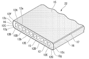
- FIG. 1 shows a cross-sectional structure of a flat tube 22 applied to the heat exchanger 11 shown in FIGS. 2 and 3, and the tube 22 is extruded formed by extruding aluminum or an aluminum alloy. It is made of a tube body 12 which is a material.
- the heat exchanger 11 of the first embodiment is used as a heat exchanger for indoor / outdoor units of a room air conditioner, an outdoor unit for HVAC (Heating Ventilating Air Conditioning), a heat exchanger for automobiles, and the like. It is an all-aluminum heat exchanger.
- the tube 22 shown in FIG. 1 shows a state before brazing, and shows a state in which the brazing composition layer is coated on the outer peripheral surface of the horizontally installed tube main body 12.
- the tube body 12 has a plurality of partition walls that partition the inside of the tube body 12 into a plurality of flow paths 12D, which are short side walls 12C and 12C in which the wide front wall 12A, the back wall 12B, and the left and right ends thereof are individually connected. It is composed of 12E.
- the plurality of flow paths 12D are all formed in a rectangular similar cross-sectional shape, and in the example shown in FIG. 1, 10 flow paths 12D are formed in the tube body.
- the tube body 12 shown in FIG. 1 is an example, and the width, thickness, flatness (ratio of width and thickness) of each part, and the shape and number of flow paths 12D can all be arbitrarily set. Can be done.
- the tube body 12 is formed in a flat shape having a wide flat front surface (upper surface) 12a and a back surface (lower surface) 12b, and flat short side surfaces 12c and 12c that individually connect both end sides thereof. ing. Further, in the tube main body 12, a corner portion 12f formed in an arc shape with a predetermined curvature is formed in a portion extending from the width direction end portion of the front surface 12a to the short side surface 12c, and the short side surface 12c is formed from the width direction end portion of the back surface 12b. A corner portion 12g formed in an arc shape with a predetermined curvature is also formed in the portion leading to.
- the portions of the short side surface 12c except for the upper and lower corner portions 12f and 12g are formed in a plane shape facing the front surface 12a and the back surface 12b at a substantially right angle.
- the overall shape of the short side surface 12c is not particularly limited, and may be a configuration in which the entire short surface is a curved surface or a shape composed of two planar inclined surfaces.
- a main brazing composition layer 15 composed of a coating film of a brazing composition having a composition described later is formed on the front surface 12a and the back surface 12b. Further, in the tube body 12, a sub-brazing composition layer 16 having a composition described later is formed on the short side surface 12c.
- the sub-brazing composition layer 16 is continuously formed on the short side surface 12c of the tube body 12 via an uncoated portion 17 having a constant width along the length direction of the tube body 12.
- the uncoated portion 17 is continuously formed in the length direction of the tube main body 12 at a position along the lower end portion and a position along the upper end portion of the short side surface 12c, respectively.
- the upper corner portion 12f and the lower corner portion 12g of the tube body 12 correspond to the uncoated portion 17.
- the width of the uncoated portion 17 is preferably 0.5 mm or more and 1 mm or less. In the form shown in FIG. 1, the widths of all the uncoated portions 17 are drawn to be the same, but the widths of all the uncoated portions 17 do not have to be the same and may vary within the above range. ..
- the brazed liquid composition in an undried state is obtained by supporting both side surfaces of the tube body 12 with the guide rollers 8a described later based on FIGS. 7 and 8.
- the coating film of the above may be transferred to the guide roller 8a side, and the coating film of the brazed liquid composition in the undried state may be peeled off.
- the coating film of the brazed liquid composition in an undried state is transferred to the guide roller 8a side, the guide roller 8a is contaminated.
- the width of the uncoated portion 17 exceeds 1 mm, a sufficient amount of the coating film of the brazing composition cannot be formed on the short side surface side of the tube body 12, resulting in poor bonding between the fin 13 and the tube body 12. There is a risk.
- the main brazing composition layer 15 and the sub-brazing composition layer 16 are composed of brazing compositions having the same composition, which will be described later, and their coating amounts (thicknesses) are different. The relationship between the coating amount and the thickness of the main brazing composition layer 15 and the sub-brazing composition layer 16 will be described in detail later.
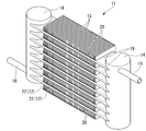
- FIG. 2 shows the overall structure of the heat exchanger 11 formed by brazing the plurality of tubes 22 shown in FIG. 1 to the header tube 14 and brazing the plurality of tubes 22 to the fins 13.
- the heat exchanger 11 is horizontally arranged between a pair of header pipes 14 arranged vertically separated from each other on the left and right sides and vertically spaced from each other between the pair of header pipes 14.
- a plurality of tubes 22 (tube body 12) joined at substantially right angles to the header tube 14 and a plurality of tubes brazed to the front surface 12a or the back surface 12b of the tube body 12 to dissipate heat to the outside air. It is equipped with fins 13.
- a supply pipe 15 for supplying a refrigerant to the tube 22 is connected to the upper end of one of the pair of left and right header pipes 14 via the header pipe 14.
- a recovery pipe 16 for recovering the refrigerant via the tube 22 is connected to the lower end of the other header pipe 14.
- the tube 22, fin 13, header pipe 14, supply pipe 15, and recovery pipe 16 are all made of aluminum or an aluminum alloy.
- FIG. 3 is a partial cross-sectional view of the heat exchanger 11 having a cross section taken along a plane orthogonal to the length direction of the tube 22.
- a plurality of (10 in this embodiment) refrigerant flow paths 12D arranged along the width direction are formed inside the tube main body 12 constituting the tube 22.
- a plurality of slit-shaped holes 19 having a shape corresponding to the cross-sectional shape of the tube 22 are formed horizontally in the fins 13 at predetermined intervals in the vertical direction. As shown in FIG. 3, these hole portions 19 are formed from the left end portion to the vicinity of the right end portion of the fin 13, and the innermost portion of the hole portion 19 is located slightly in front of the right end portion of the fin 13. .
- a tube 22 is fitted into each of these holes 19, and each tube 22 is fixed to a plurality of fins 13 by brazing.
- the length of the hole 19 formed in the fin 13 (horizontal length shown in FIG. 3) is slightly shorter than the width of the fin 13, and the short side surface of the tube 22 inserted into the hole 19 on one side in the width direction. 12c is inserted to the innermost part of the hole 19 and brazed.
- FIGS. 4 and 5 are partial cross-sectional views taken along the length direction of the tube 22 in the heat exchanger 11 shown in FIGS. 2 and 3, and FIG. 4 shows a state before brazing.
- FIG. 5 shows the state after brazing.
- a plurality of fins 13 are arranged in parallel along the length direction of the tube 22 (along the left-right direction of FIGS. 4 and 5), and the tube 22 is inserted into each hole 19.
- the plurality of fins 13 are arranged in parallel with each other at regular intervals.
- the fin 13 has a bent portion 20 that is bent to one side in the thickness direction of the fin 13 along the peripheral edge portion of the hole portion 19.
- the bent portion 20 is formed by a processing method such as burring.
- the tube 22 and the fin 13 are arranged so that the tube 22 skewers and penetrates a plurality of fins 13 arranged at regular intervals, and the fin 13 and the tube 22 are individually fixed by brazing.
- the gap between the bent portion 20 formed in the hole 19 of the fin 13 and the front surface or the back surface of the tube 22 is formed to be about 10 ⁇ m or less. If this gap is too large, the amount of wraparound of the melted brazing in the brazing step described later is insufficient, which may cause poor brazing.
- the fin 13 has a plate-shaped base material 3 and a hydrophilic film 1 coated on the first surface 3a and the second surface 3b of the base material 3.
- the base material 3 of the fin 13 is made of a pure aluminum alloy such as JIS1050 or an alloy mainly composed of JIS3003 aluminum alloy.
- the base material 3 may be made of an aluminum alloy in which Zn of about 2% by mass is added to a JIS3003 series aluminum alloy.
- the base material 3 of the fin 13 is formed by melting the aluminum alloy by a conventional method and passing through a hot rolling step, a cold rolling step, a pressing step and the like.
- the method for producing the base material 3 is not particularly limited in the present invention, and a known production method can be appropriately adopted.
- the aluminum alloy constituting the header pipe 14 is preferably an aluminum alloy based on an Al—Mn system.
- Mn 0.05 to 1.50%
- Cu 0.05 to 0.8%
- Zr 0.05 to 0.15% may be contained. it can.
- the tube 22 before brazing has a tube main body 12 and brazing composition layers 15 and 16 formed on the outer peripheral surface thereof.
- the tube body 12 is made of, for example, a pure aluminum alloy such as JIS1050 or an alloy mainly composed of JIS3003 aluminum alloy.
- Si 0.10 to 0.60%
- Fe 0.1 to 0.6% by mass
- Mn 0.1 to 0.6% by mass
- Ti 0.005 to 0.2% by mass
- Cu It is made of an aluminum alloy having less than 0.1% by mass and the balance consisting of aluminum and unavoidable impurities, and is produced by extruding these aluminum alloys.
- the main brazing composition layer 15 formed on the tube body 12 before brazing shown in FIGS. 1 and 4 is a coating film applied at least to the portion where the fins 3 are brazed and joined.
- the main brazing composition layer 15 contains Si powder: 1 to 5 g / m 2 , Zn-containing flux (for example, KZnF 3 ): 3 to 20 g / m 2 , and non-Zn-containing flux: 1 to 10 g / m. It is preferably composed of a dried product of a brazing coating film containing any one or more of m 2 and further containing a binder (for example, acrylic resin): 0.2 to 8.5 g / m 2.
- a binder for example, acrylic resin
- a brazing liquid composition is formed by blending an appropriate amount of solvent with these components, and the brazing liquid composition is applied to the front surface or the back surface of the tube body 12 to form a brazing liquid composition.
- the main brazing composition layer 15 is obtained by forming the coating film of the above and drying the coating film.
- the Si powder reacts with Al constituting the tube body 12 at the time of brazing to form a wax that joins the fin 3 and the tube body 12, but the Zn-containing flux and the Si powder are melted at the time of brazing to become a brazing liquid. .. Zn in the flux diffuses uniformly in this brazing liquid and spreads uniformly on the front surface and the back surface of the tube body 12.
- this Zn melt diffusion layer serves as a sacrificial anode layer, the corrosion resistance of the brazed portions on the front surface side and the back surface side of the tube body 12 can be improved.
- the sub-brazing composition layer 16 is also formed on the short side surface side of the tube body 12, Zn and Si contained in these brazing composition layers 16 are diffused, and the tube is formed.
- a sacrificial anode layer is also formed on the short side surface side of the main body 12.
- Si powder coating amount 1 to 5 g / m 2 > If the coating amount of Si powder is less than 1 g / m 2 , wax formation may be insufficient, and if the coating amount exceeds 5 g / m 2 , the melting amount of the tube body 12 increases and the tube body 12 The wall thickness of the is reduced, which is not preferable. Therefore, the content of the Si powder in the main brazing composition layer 15 is preferably 1 to 5 g / m 2 .
- the Zn-containing flux has the effect of forming Zn melt diffusion layers on the front surface side and the back surface side of the tube body 12 and improving pitting corrosion resistance during brazing. Further, at the time of brazing, the oxide film on the outer surface of the tube 3 is destroyed, the spread and wetting of the wax are promoted, and the brazing property is improved. Since this Zn-containing flux has a higher activity than the Zn-free flux, good brazing property can be obtained even if a relatively fine Si powder is used.
- the Zn-containing flux one or more of KZnF 3 , ZnF 2 , and ZnCl 2 can be used.
- a non-Zn-containing flux may be added to the Zn-containing flux.
- Flux of the fluoride-based flux or potassium fluoroaluminate-based way of non-Zn-containing flux is a flux mainly composed of KAlF 4, various compositions are known plus additives. Examples thereof include those having a composition of K 3 AlF 6 + KAlF 4 (K 1-3 AlF 6-4 ), Cs (x), K (y), F (z), and the like.
- a fluoride-based flux for example, a potassium fluoroaluminate-based flux
- a fluoride-based flux for example, a potassium fluoroaluminate-based flux
- a fluoride-based flux for example, a potassium fluoroaluminate-based flux
- a fluoride-based flux for example, a potassium fluoroaluminate-based flux
- ⁇ Flux coating amount 3 to 20 g / m 2 > If the coating amount of the Zn-containing flux is less than 3 g / m 2 , the potential difference when the heat exchanger 11 is used becomes low, and the sacrificial effect may not be exhibited. Further, since the surface oxide film of the tube body 12 is not sufficiently destroyed and removed, brazing failure may occur. On the other hand, if the coating amount exceeds 20 g / m 2 , the potential difference becomes excessive, the corrosion rate increases, and the anticorrosion effect due to the presence of the Zn melt diffusion layer may be shortened. Therefore, it is preferable that the coating amount of the Zn-containing flux is 3 to 20 g / m 2 . As the Zn-containing flux, KZnF 3 can be used as an example. The above-mentioned non-Zn-containing flux can be added in addition to the Zn-containing flux.
- the brazing composition layer 15 can contain a binder in addition to the Si powder and the Zn-containing flux.
- Acrylic resin can be mentioned as an example of a binder.
- the binder has the function of fixing the Si powder and the Zn-containing flux necessary for forming the Zn melt diffusion layer to the front surface and the back surface of the tube 22, but if the amount of the binder applied is less than 0.2 g / m 2, it is brazed. Occasionally, Si powder or Zn flux may fall off from the tube body 12, and a uniform Zn melt diffusion layer may not be formed.
- the amount of the binder applied is preferably 0.2 to 8.5 g / m 2 .
- the binder is usually transpired by heating during brazing.
- the method for forming the brazing composition layer 15 composed of Si powder, flux and binder is not particularly limited in this embodiment, and the spray method, shower method, flow coater method, bar coater method, roll coater method, and brushing method are used. It can be carried out by an appropriate method such as a coating method, a dipping method, or an electrostatic coating method.
- the sub-brazing composition layer 16 formed on the side surface side of the tube main body 12 shown in FIG. 1 is basically made of the same material as the material constituting the main brazing composition layer 15. That is, it contains one or more of Si powder, Zn-containing flux, and non-Zn-containing flux, and further contains a binder. Alternatively, it is composed of a composition containing one or more of Si powder, Zn-containing flux and non-Zn-containing flux, and further adding a solvent to a binder. However, it is preferable that the sub-brazing composition layer 16 is formed in a coating amount (thickness) 1 to 5 times the coating amount (thickness) of the main brazing composition layer 15.
- the coating amount of the sub-brazing composition layer 16 is less than 1 times the coating amount of the main brazing composition layer 15, the brazing property and corrosion resistance may be insufficient.
- the coating amount of the secondary brazing composition layer 16 exceeds 5 times the coating amount of the main brazing composition layer 15, the amount of brazing material (Si amount) between the fin 13 and the tube body 12 becomes too large.
- the corrosion rate of the tube body 12 and the fins 13 becomes too high, and there is a possibility that problems such as through holes are likely to occur in the tube body 12 or the fins 13 due to corrosion.
- the sub-brazing composition layer 16 is formed on the short side surface of the tube body 12. At the time of brazing, the sub-brazing composition layer 16 melts and solidifies, and the short side surface side of the tube body 12 is brazed and fixed to the innermost side of the hole 19 of the fin 13. Without the sub-brazing composition layer 16, the fixing force for brazing and fixing the short side surface side of the tube body 12 to the fins 13 is insufficient.
- a configuration in response to the demand for miniaturization and compactification of the outdoor unit, a configuration is known in which a part of the heat exchanger is bent into an L-shape in a plan view and housed in the outdoor unit.
- a part of the heat exchanger is bent into an L shape in a plan view in this way, if the force for brazing and fixing the short side surface side of the tube body 12 to the innermost side of the hole 19 of the fin 13 is insufficient. A part of the plurality of fins 13 may fall down at the bent portion. If the sub-brazing composition layer 16 provided on the short side surface side of the tube body 12 has a sufficient thickness, the brazing fixing force of the fins 13 can be sufficiently secured.
- the tube body 12 can be bent without causing the fins to fall.
- the number of refrigerant flow paths in the tube body 12 is reduced to adopt a structure having a low flatness. ..
- FIG. 4 shows a vertical cross section of the tube body 12 inserted into the hole 19 of the fin 13, and the main brazing composition layer 15 of the tube body 12 faces the tube body 12 of the bent portion 20 of the fin 13. It is located between the portion to be brazed (opposing surface 20a) and the tube body 12.
- the main brazing composition layer 15 is cooled after heating at around 600 ° C. (brazing heating) to solidify in a state of being filled between the facing surface 20a and the tube body 12, and as shown in FIG.
- a fillet 15A is formed in the fin 13 and the tube body 12 is joined.
- the sub-brazing composition layer 16 formed on the short side surface side of the tube body 12 and its corner portion becomes a fillet after brazing, and the short side surface side of the tube body 12 is placed on the innermost side of the hole portion 19. Join.
- the main brazing composition layer 15 is formed in a region in contact with the fins 13, that is, on the front surface 12a and the back surface 12b of the tube body 12. Further, Si and Zn contained in the main brazing composition layer 15 before brazing diffuse to the tube body 12 side at the brazing temperature, and the surface layer portion of the front and back surfaces of the tube body 12 contains Si and Zn. Form an anode layer. Further, Si and Zn contained in the sub-brazing composition layer 16 are also diffused to the short side surface side of the tube body 12 at the time of brazing, and a sacrificial anode layer containing Si and Zn is formed in these portions.
- a sacrificial anode layer can be formed on the entire circumference of the tube body 12 in the portion where the sub-brazing composition layer 16 is provided. Therefore, the corrosion resistance on the short side surface of the tube body 12 can be improved.
- the method of forming the main brazing composition layer 15 and the sub-brazing composition layer 16 on the tube body 12 and the method of drying them will be described below.
- the method for forming the main brazing composition layer 15 composed of Si powder, flux, and binder is not particularly limited in this embodiment.
- a paint obtained by adding a solvent to Si powder, a flux, and a binder to form a brazed liquid composition may be applied by the following method and dried.
- the coating can be applied by an appropriate method such as a spray method, a shower method, a flow coater method, a bar coater method, a roll coater method, a brush coating method, a dipping method, or an electrostatic coating method.
- the main brazing composition layer 15 can be formed in a required range on the front surface 12a and the back surface 12b of the tube body 12 with a required coating amount.
- the main brazing composition layer 15 can be formed on substantially the entire surface of the front surface 12a and the back surface 12b of the tube body 12.
- the brazed liquid composition used here is the above-mentioned Si powder, a Zn-containing flux (for example, KZnF 3 ), and a binder (for example, an acrylic resin) to which a required amount of solvent is added to obtain a viscosity desirable for an inkjet method.
- a Zn-containing flux for example, KZnF 3
- a binder for example, an acrylic resin
- the above-mentioned Si powder, Zn-containing flux (for example, KZnF 3 ), non-Zn-containing flux, and binder (for example, acrylic resin) are added with a required amount of solvent to obtain a liquid having a viscosity desirable for the inkjet method.
- It means a liquid composition with a wax.
- it means a brazed liquid composition obtained by adding a necessary amount of solvent to the above-mentioned Si powder, a non-Zn-containing flux, and a binder (for example, an acrylic resin) to obtain a liquid having a viscosity desirable for an inkjet method.
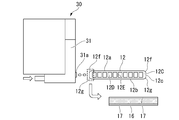
- the coating device 30 shown in FIG. 6 is a piezo injection type coating device having a nozzle 31a in the head portion 31.
- the brazing liquid composition contained in a tank (not shown) is guided to the head portion 31 and head portion 31. It is configured so that a predetermined amount of brazed liquid composition can be injected from the tip of the nozzle 31a using a piezo type injector built in the nozzle 31a.
- a piezo type injector A piezo element that expands and contracts when a voltage is applied is provided in a part of the liquid chamber, and the liquid in the liquid chamber is liquid from the head part connected to a part of the liquid chamber according to the expansion and contraction of the piezo element. It is a coating device that can be sprayed as drops.
- the coating device 30 is provided with a head moving mechanism (not shown) that supports the head portion 31 so as to be movable in a predetermined range in a three-dimensional direction (XYZ direction) at high speed, and the purpose is to respond to the movement of the head portion 31.
- a coating film of a brazed liquid composition having a desired thickness can be formed in the range of.
- the tube body is arranged in front of the nozzle 31a by injecting droplets of the brazed liquid composition at a discharge cycle of 100 to 1200 Hz with a discharge opening diameter of 0.3 mm of the nozzle 31a.
- a coating film of a brazed liquid composition having a thickness of about 1 ⁇ m to 50 ⁇ m can be continuously formed on the short side surface 12c of 12.
- this coating device 30 is used to apply a coating film of a brazed liquid composition on the short side surface side of the tube body 12 along the length direction of the tube body via one or more uncoated portions 17.
- the brazing composition coating film 16a can be continuously formed.
- an end face coating device manufactured by SSI Japan Co., Ltd. can be used.
- FIG. 6 the description of the main brazing composition layer 15 formed in the previous step on the upper and lower surfaces of the tube main body 12 is omitted, and only the sub-brazing composition layer 16 is shown.
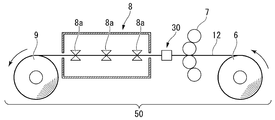
- FIG. 7 shows a winding roller 6 capable of unwinding the tube body 12, a coater 7 capable of applying the brazing liquid composition, a coating device 30, and a drying furnace 8 for drying the coating film of the brazing liquid composition.
- the unwinding roller 6 is a roller capable of winding and holding the tube body 12 having a required length, and unwinding the tube body 12 as needed.
- the coater 7 is composed of a plurality of rolls combined vertically, and a liquid brazing composition contained in a tank (not shown) is pumped up by the plurality of rolls, and the front surface and the back surface of the tube body 12 passing between the upper and lower rolls.
- a coating device capable of forming a coating film of a brazing liquid composition (main brazing composition coating film).
- the coating device 30 of this example includes two head portions 31 provided with the nozzles 31a described above, and coats the desired secondary brazing composition on both short sides of the tube body 12 while the tube body 12 passes through the coating device 30.
- This is a coating device capable of continuously forming the film 16a via the uncoated portion 17.
- the drying furnace 8 has a plurality of drum-shaped guide rolls 8a and a heater (not shown) in the furnace, and may be applied to the tube body 12 while the tube body 12 is being conveyed along the plurality of guide rolls 8a.
- a drying furnace capable of heating and drying a coating film of a liquid composition to fix it.
- paired drum-shaped guide rolls 8a are arranged so as to be separated from each other from the inlet side to the outlet side of the drying furnace 8.
- the tube body 12 can be conveyed while being horizontally supported while sandwiching the tube body 12 between the guide rolls 8a arranged on the left and right.
- the brazing composition coating film applied to the front surface and the back surface of the tube body 12 and both short side surfaces is omitted, and only the approximate shape of the tube body 12 is drawn.
- the guide rolls 8a and 8a horizontally convey the tube body 12 while being in contact with both side surfaces of the tube body 12. Therefore, the sub-brazing composition coating film 16a formed on both short side surfaces 12c of the tube body 12 may come into contact with the peripheral surfaces of the guide rolls 8a and 8a and be transferred or peeled off to the guide roll side.
- the sub-brazing composition coating film 16a is formed on both short side surfaces of the tube body 12 via the uncoated portion 17 having a width of 0.5 mm or more and 1 mm or less, the sub-brazing composition coating film is applied.
- the film 16a and the peripheral surfaces of the guide rolls 8a and 8a are no longer in contact with each other, and the sub-brazing composition coating film 16a is not peeled off.
- the guide roll 8a horizontally conveys the tube body 12 while only a part of the inner peripheral surface 8b is in contact with the lower end of the short side surface of the tube body 12 in the horizontal state. That is, on the short side surfaces 12c on both sides of the tube body 12 shown in FIG. 8, only the corner portion of the lower end of the short side surface contacts the inner peripheral surface 8b of the guide roll 8a. Therefore, strictly speaking, if the uncoated portion 17 is formed only on the lower end portion of the short side surface 12c, the object may be achieved.
- the contact position between the tube body 12 and the inner peripheral surface 8b of the guide roll 8a is slightly different during transportation. It is preferable that the uncoated portion 17 is formed on the lower portion and the upper portion of the short side surface 12b in consideration of moving up and down and slightly moving back and forth.
- the coating film of the main brazing liquid composition and the coating film 16a of the secondary brazing liquid composition are gradually dried, and the main brazing composition layer 15 and the secondary brazing composition layer are gradually dried. 16 is formed.
- the main brazing composition layer 15 and the sub-brazing composition layer 16 are fixed to the tube body 12 and adhere to the tube body 12, so that these composition layers are difficult to peel off.
- the tubes 22 are inserted into the holes 19 of the fins 13 installed in parallel and fitted, and assembled in a state close to FIG. Braze.
- Brazing is performed by performing a brazing step of heating the brazing composition layers 15 and 16 to a temperature equal to or higher than the melting point, for example, 580 to 620 ° C. in a heating furnace for about several minutes.
- the brazing composition layers 15 and 16 are melted into a brazing liquid.
- This brazing liquid flows into the gap between the tube body 12 and the bent portion 20 of the fin 13, and fills these gaps.
- the wax solution described above also flows into a gap on the short side surface side of the tube body 12 fitted at the innermost position of the hole 19 to fill this gap.
- the waxy liquid solidifies and a fillet 15A is formed.
- the tube body 12 and the fins 13 are brazed and joined by these fillets 15A.
- Si and Zn in the flux are diffused by brazing, and a Zn molten diffusion layer (sacrificial anode layer) is formed on the short side surface in addition to the front and back surfaces of the tube body 12. It is formed.
- the brazing composition layer 16 is formed after the main brazing composition layer 15 is formed, but the order in which these are formed may be any first, and these may be formed at the same time. ..
- the brazing composition layer 16 is formed on the short side surface side by the coating device 30, and then the main brazing composition layer 15 is formed on the front and back surfaces using a bar coater or a roll coater. May be formed.
- the main brazing composition layer 15 is formed on the front and back surfaces by using a bar coater or a roll coater, and the brazing composition is continuously formed on the short side surface side by the coating device 30 provided adjacent to the bar coater or the roll coater.
- the material layer 16 may be formed. After forming these composition layers on a long tube body 12 made of extruded material, the tube body 12 is cut to a required length to obtain a brazing tube 22 for a heat exchanger.
- the heat exchanger 11 can be configured by brazing a tube 22 provided with the brazing composition layers 15 and 16 in combination with a plurality of fins 13.
- the brazing composition layer 15 provided on the front and back sides of the tube body 12 can reliably braze the fins 13 on the front and back sides of the tube body 12.
- the brazing composition layer 16 provided on the short side surface side of the tube body 12 can reliably braze the short side surface side of the tube body 12 to the fins 13. Therefore, the entire tube body 12 can be reliably brazed to the fins 13 with sufficient bonding strength. That is, high quality brazing joints can be made in the heat exchanger 11.
- Zn can be diffused not only on the front surface side and the back surface side of the tube 12 but also on the short side surface side, and the entire circumference of the tube 12 is sacrificed.
- An anode layer can be formed.
- the width of the uncoated portion 17 is set to the minimum required of 0.5 mm or more and 1 mm or less, the brazing property is not adversely affected, and a sacrificial anode layer is formed by Zn diffusion from both sides of the uncoated portion 17. Therefore, it is possible to provide the heat exchanger 11 having good corrosion resistance by appropriately controlling the corrosion rate by the diffusion progress of Zn with respect to the uncoated portion 17 as well as the coated portion.
- the portion where the sacrificial anode layer is formed proceeds to corrode not as pitting corrosion but as surface corrosion, it is possible to provide a structure in which the tube body 12 is less likely to have through holes due to corrosion. Further, by forming the sacrificial anode layer on the entire circumference of the tube body 12, it is possible to provide the heat exchanger 11 having an anticorrosive structure capable of suppressing corrosion of the brazed portion adjacent to the sacrificial anode layer.
- a brazing composition layer containing Si powder and a Zn-containing flux may be formed on both the front surface / back surface side and the short side surface of the tube 12. Further, a brazing composition layer containing Si powder, Zn-containing flux and non-Zn-containing flux may be formed on both the front surface / back surface side and the short side surface of the tube 12.
- composition layer containing a non-Zn-containing flux may be formed on both the front surface / back surface side and the short side surface of the tube 12. Further, a composition layer containing a Zn-containing flux may be formed on both the front surface / back surface side and the short side surface of the tube 12.
- a composition layer containing a Zn-containing flux and a non-Zn-containing flux may be formed on both the front surface / back surface side and the short side surface of the tube 12.
- the brazing material can be supplied to the joint portion by using a brazing sheet, a brazing rod, or the like.
- a brazing composition layer containing Si powder and a Zn-containing flux may be formed on the front and back surfaces of the tube 12, and a composition layer containing a Zn-containing flux may be formed on the short side surface of the tube 12. Further, a brazing composition layer containing Si powder, Zn-containing flux and non-Zn-containing flux is formed on the front and back surfaces of the tube 12, and a composition containing Zn-containing flux and non-Zn-containing flux on the short side surface of the tube 12. Layers may be formed.
- a composition layer containing a non-Zn-containing flux may be formed on the front surface and the back surface side of the tube 12, and a brazing composition layer containing a Si powder and a Zn-containing flux may be formed on the short side surface of the tube 12. Further, a composition layer containing a non-Zn-containing flux is formed on the front surface and the back surface side of the tube 12, and a brazing composition layer containing Si powder, a Zn-containing flux and a non-Zn-containing flux is formed on the short side surface of the tube 12. You may.
- a composition layer containing a Zn-containing flux may be formed on the front and back surfaces of the tube 12, and a brazing composition layer containing a Si powder and a Zn-containing flux may be formed on the short side surface of the tube 12. Further, a brazing composition containing a Zn-containing flux and a non-Zn-containing flux on the front and back surfaces of the tube 12 and a Si powder, a Zn-containing flux and a non-Zn-containing flux on the short side surface of the tube 12. Layers may be formed.
- a flat multi-hole tube made of an aluminum alloy containing Si: 0.3 to 0.5% by mass and Mn: 0.2 to 0.4% by mass and composed of unavoidable impurities and Al was prepared.
- This flat multi-hole tube has a width of 17 mm, a thickness of 1.5 mm, and a corner portion having a radius of curvature of 0.3 mm at the corner portion of the boundary between the front and back surfaces and the short side surface.
- the coating film was Si powder: 3 g / m 2 , Zn-containing flux (KZnF 3 ): 6 g / m 2 , and acrylic as a binder.
- the system resin was applied so as to have a ratio of 1 g / m 2 .
- the coating film was Si powder: 0.9 g / m 2 , Zn-containing flux (KZnF 3 ): 2.9 g / m 2 , and acrylic resin as a binder: 0.2 g / m 2 . It was applied in proportion.
- the coating film has a ratio of Si powder: 1 g / m 2 , Zn-containing flux (KZnF 3 ): 3 g / m 2 , and acrylic resin as a binder: 0.2 g / m 2.
- the coating film has a ratio of Si powder: 1 g / m 2 , Zn-containing flux (KZnF 3 ): 3 g / m 2 , and acrylic resin as a binder: 0.2 g / m 2.
- the coating film has a ratio of Si powder: 5 g / m 2 , Zn-containing flux (KZnF 3 ): 20 g / m 2 , and acrylic resin as a binder: 8.5 g / m 2.
- the coating film was Si powder: 5.2 g / m 2 , Zn-containing flux (KZnF 3 ): 20.2 g / m 2 , and acrylic resin as a binder: 8.6 g / m 2 . It was applied in proportion.
- Examples 18 to 34, 103 to 119 and Comparative Examples 5 to 8 and 25 to 28 Si powder, Zn-containing flux (KZnF 3 ), and non-Zn-containing flux were used on the front and back surfaces of the flat multi-hole tube using a roll coater. (K 1-3 AlF 6-4 ), a brazing liquid composition in which an acrylic resin as a binder was dispersed in a solvent was applied.
- the coating film was Si powder: 3 g / m 2 , Zn-containing flux (KZnF 3 ): 5 g / m 2 , non-Zn-containing flux.
- the coating film was Si powder: 1 g / m 2 , Zn-containing flux (KZnF 3 ): 3 g / m 2 , non-Zn-containing flux (KZnF 3 ): 1 g / m 2 , acrylic as a binder.
- the system resin was applied so as to have a ratio of 0.2 g / m 2 .
- the coating film was Si powder: 5 g / m 2 , Zn-containing flux (KZnF 3 ): 20 g / m 2 , non-Zn-containing flux (KZnF 3 ): 10 g / m 2 , and acrylic as a binder.
- the coating was applied so as to have a ratio of 8.5 g / m 2 .
- the coating film was Si powder: 5.1 g / m 2 , Zn-containing flux (KZnF 3 ): 20.2 g / m 2 , and non-Zn-containing flux (KZnF 3 ): 10.1 g / m. 2.
- Acrylic resin as a binder 8.6 g / m 2 was applied.
- a non-Zn-containing flux (K 1-3 AlF 6-4 ) was used on the front surface and the back surface of the flat multi-hole tube using a roll coater.
- a liquid composition in which an acrylic resin as a binder was dispersed in a solvent was applied.
- the coating film was a non-Zn-containing flux (K 1-3 AlF 6-4 ): 9 g / m 2 , as a binder. Acrylic resin of 1 g / m 2 was applied.
- the coating film was applied so as to have a non-Zn-containing flux (KZnF 3 ): 0.8 g / m 2 and an acrylic resin as a binder: 0.2 g / m 2 . ..
- the coating film was applied at a ratio of non-Zn-containing flux (KZnF 3 ): 1 g / m 2 and acrylic resin as a binder: 0.2 g / m 2 .
- Example 50 the coating film was applied at a ratio of non-Zn-containing flux (KZnF 3 ): 10 g / m 2 and acrylic resin as a binder: 8.5 g / m 2 .
- KZnF 3 non-Zn-containing flux
- acrylic resin as a binder 8.5 g / m 2 .
- Example 51,135,153 coatings, non-Zn-containing flux (KZnF 3): 10.4g / m 2, an acrylic resin as a binder: was coated to a rate of 8.6 g / m 2 ..
- Example 52 to 68, 154 to 170 and Comparative Examples 13 to 16, 37 to 40 a roll coater was used on the front surface and the back surface of the flat multi-hole tube, and a Zn-containing flux (KZnF 3 ) and an acrylic resin as a binder were used.
- a Zn-containing flux (KZnF 3 ) and an acrylic resin as a binder were used.
- the coating film was made of Zn-containing flux (KZnF 3 ): 9 g / m 2
- acrylic resin as a binder 1 g / m 2 . It was applied in proportion.
- the flux was applied so as to have a ratio of Zn-containing flux (KZnF 3 ): 2.8 g / m 2 and acrylic resin as a binder: 0.2 g / m 2 .
- the flux was applied so as to have a ratio of Zn-containing flux (KZnF 3 ): 3 g / m 2 and acrylic resin as a binder: 0.2 g / m 2 .
- the flux was applied so as to have a ratio of Zn-containing flux (KZnF 3 ): 20 g / m 2 and acrylic resin as a binder: 8.5 g / m 2 .
- an acrylic resin as a binder was coated to a rate of 8.6 g / m 2.
- Examples 69 to 85, 171 to 187 and Comparative Examples 17 to 20, 41 to 44 Zn-containing flux (KZnF 3 ) and non-Zn-containing flux (K) were used on the front and back surfaces of the flat multi-hole tube. 1-3 AlF 6-4 ), a liquid composition in which an acrylic resin as a binder was dispersed in a solvent was applied.
- the coating film was Zn-containing flux (KZnF 3 ): 5 g / m 2 , non-Zn-containing flux (K 1-3 AlF 6-).
- the coating film had a Zn-containing flux (KZnF 3 ): 2.9 g / m 2 , a non-Zn-containing flux: 0.9 g / m 2 , and an acrylic resin as a binder: 0.2 g / m. It was applied so as to have a ratio of 2 .
- the coating film had a ratio of Zn-containing flux (KZnF 3 ): 3 g / m 2 , non-Zn-containing flux: 1 g / m 2 , and acrylic resin as a binder: 0.2 g / m 2 . It was applied so as to become.
- the coating film had a ratio of Zn-containing flux (KZnF 3 ): 20 g / m 2 , non-Zn-containing flux: 10 g / m 2 , and acrylic resin as a binder: 8.5 g / m 2 . It was applied so as to become.
- Example 85 187, the coating film, the Zn-containing flux (KZnF 3): 20.2g / m 2, the non-Zn containing flux: 10.2 g / m 2, an acrylic resin as a binder: 8.6 g / m It was applied so as to have a ratio of 2 .
- a coating film of the brazed liquid composition was intermittently continuously applied to both short sides of the flat multi-hole tube via an uncoated portion using an end face coating device manufactured by SSI Japan Co., Ltd. Formed.
- the discharge opening diameter of the inkjet coating device was 0.3 mm, and the discharge cycle was set to 600 to 1200 Hz.
- the short side surface of the flat multi-hole tube is compared with the example shown in Table 1 described later while moving the long extruded flat multi-hole tube in the length direction at a moving speed of 1.0 m / s.
- a coating film composed of a brazed liquid composition was continuously formed through an uncoated portion having a length (width) of 0.4 mm to 1.1 mm.
- the amount of coating film applied to the short side surface is 0.8 times, 1 time, 3 times, 5 times, and 5.5 times that of the front and back surfaces, and the Si powder: 2.4, 3, 9, 15, 16.5 g / m 2 , Zn-containing flux (KZnF 3 ): 4.8, 6, 18, 30, 33 g / m 2 , acrylic resin as binder: 0.8, 1, 3, 5 , 5 It was applied at a ratio of .5 g / m 2 .
- the applied liquid composition for brazing includes Si powder (D (99) particle size 10 ⁇ m), Zn-containing flux (KZnF 3 powder: D (50) particle size 2.0 ⁇ m), acrylic resin binder, and 3- as a solvent. It is a brazed liquid composition consisting of a mixture of methoxy-3-methyl-1-butanol and isopropyl alcohol.
- Examples 18 to 34, 137 to 153, 171 to 187 and Comparative Examples 5 to 8, 33 to 36, 41 to 44, Si powder and Zn-containing flux (KZnF 3) were formed on the short side surface of the flat multi-hole tube by the above method.
- Non-Zn-containing flux K 1-3 AlF 6-4
- waxed liquid composition in which an acrylic resin as a binder is dispersed in a solvent (mixture of 3-methoxy-3-methyl-1-butanol and isopropyl alcohol). I applied the thing.
- Si powder 2.4, 3, 9, 15, 16.5 g / m 2
- Zn-containing flux KZnF 3
- Non-Zn-containing flux K 1-3 AlF 6-4
- an acrylic resin as a binder was coated to a ratio of 1 g / m 2.
- the applied liquid composition for brazing includes Si powder (D (99) particle size 10 ⁇ m), Zn-containing flux (KZnF 3 powder: D (50) particle size 2.0 ⁇ m), and non-Zn-containing flux (K 1-3 AlF).
- 6-4 powder A brazed liquid composition comprising a D (50) particle size of 2.0 ⁇ m), an acrylic resin binder, and a mixture of 3-methoxy-3-methyl-1-butanol as a solvent and isopropyl alcohol.
- a non-Zn-containing flux (K 1-3 AlF 6-4 ) and an acrylic resin as a binder are used as a solvent (3) on the short side surface of the flat multi-hole tube by the above method.
- a liquid composition dispersed in a mixture of -methoxy-3-methyl-1-butanol and isopropyl alcohol) was applied.
- the coating film is a non-Zn-containing flux (K 1-3 AlF 6) when the amount applied to the short side surface is 0.8 times, 1 time, 3 times, 5 times, and 5.5 times that of the front and back surfaces.
- the applied liquid composition for brazing is a non-Zn-containing flux (K 1-3 AlF 6-4 powder: D (50) particle size 2.0 ⁇ m), an acrylic resin binder, and 3-methoxy-3-methyl as a solvent.
- a brazed liquid composition consisting of a mixture of -1-butanol and isopropyl alcohol.
- a Zn-containing flux (KZnF 3 ) and an acrylic resin as a binder are used as a solvent (KZnF 3 ) on the short side surface of the flat multi-hole tube by the above method.
- a liquid composition dispersed in a mixture of 3-methoxy-3-methyl-1-butanol and isopropyl alcohol) was applied.
- the coating film has a Zn-containing flux (KZnF 3 ): 7.2 when the amount applied to the short side surface is 0.8 times, 1 time, 3 times, 5 times, and 5.5 times that of the front and back surfaces.
- the applied liquid composition for brazing includes a Zn-containing flux (KZnF 3 powder: D (50) particle size 2.0 ⁇ m), an acrylic resin binder, 3-methoxy-3-methyl-1-butanol as a solvent, and isopropyl alcohol. It is a brazing liquid composition consisting of a mixture of.
- Zn-containing flux (KZnF 3 ) and non-Zn-containing flux (K 1-3 ) were formed on the short side surface of the flat multi-hole tube by the above method.
- AlF 6-4 a brazing liquid composition in which an acrylic resin as a binder was dispersed in a solvent (a mixture of 3-methoxy-3-methyl-1-butanol and isopropyl alcohol) was applied.
- the coating film has a Zn-containing flux (KZnF 3 ): 4, 5 when the amount applied to the short side surface is 0.8 times, 1 time, 3 times, 5 times, and 5.5 times that of the front and back surfaces.
- the applied liquid composition for brazing includes a Zn-containing flux (KZnF 3 powder: D (50) particle size 2.0 ⁇ m) and a non-Zn-containing flux (K 1-3 AlF 6-4 powder: D (50) particle size. 0 ⁇ m), a brazed liquid composition comprising an acrylic resin binder, a mixture of 3-methoxy-3-methyl-1-butanol as a solvent and isopropyl alcohol.
- the coating amount of the liquid composition on the short side surface in Examples 1 to 187 and Comparative Examples 1 to 44 is shown in Tables 1 to 8 as a multiple of the coating amount on the front surface and the back surface.
- the flat multi-hole tube is introduced into a drying oven equipped with 12 pairs of guide rolls 8a as shown in FIGS. 7 and 8, and while passing through the drying oven.
- a brazing tube having a brazing composition layer on the front and back surfaces and short side surfaces is manufactured by carrying out the drying process under the above conditions, the guide roller in the drying furnace is visually observed after the drying process is completed, and the guide roller is used.
- the paint of the brazed liquid composition adhered to the peripheral surface of the surface, it was judged that there was paint, and when the paint did not adhere, it was judged that there was no paint and evaluated.
- a brazing tube coated with a brazing composition layer was fitted into each hole formed in the fins arranged in parallel as described above, and a heat exchanger mini-core body was assembled.
- the assembled heat exchanger mini-core body was heated to 600 ° C. for 3 minutes in a brazing furnace in a nitrogen gas atmosphere and brazed.
- a sub-brazing composition layer is intermittently continuously provided on the short side surface of the flat multi-hole tube along the length direction of the tube via an uncoated portion.
- the paint of the brazed liquid composition adheres to the guide roller side while ensuring excellent brazing bondability by providing an uncoated portion having a length (width) of 0.5 mm or more and 1.0 mm or less. I was able to realize a configuration that does not allow it.
- a sub-brazing composition layer in a coating amount range of 1 to 5 times the coating amount of the main brazing composition layer coated on the front and back surfaces of the flat multi-hole tube is formed on the short side surface of the flat multi-hole tube.
- a heat exchanger having a structure in which the paint of the brazing liquid composition does not adhere to the guide roller side, has excellent brazing property, and has good corrosion resistance can be obtained.
- Comparative Examples 1, 5, 9, 13, 17, 21, 25, 29, 33, 37 and 41 shown in Tables 7 to 8 the length (width) of the uncoated portion was reduced to 0.4 mm.
- Comparative Examples 2, 6, 10, 14, 18, 22, 26, 30, 34, 38, and 42 shown in Tables 7 to 8 are samples in which the length of the uncoated portion is increased to 1.1 mm, but guides are provided. No transfer of the brazing liquid paint to the roller occurred, but the length (width) of the uncoated portion was large, so that both the brazing property and the corrosion resistance were deteriorated.
- brazing tube that prevents the brazing composition on the short side surface side from peeling off in a flat tube body and ensures excellent corrosion resistance and brazing property on the short side surface side of the tube body. become able to.
Abstract
This brazing tube (22) is made from aluminum or an aluminum alloy and comprises a flat tube main body (12) with a front surface (12a), a back surface (12b), and short-side surfaces (12c), a brazing composition layer (16) being formed on the short-side surfaces (12c), wherein: the brazing composition layer is formed continuously, in the longitudinal direction of the tube main body (12), on the short-side surfaces (12c) with at least one uncoated section (17) interposed therebetween; and the width of the uncoated section (17), which follows the longitudinal direction of the tube main body, is 0.5–1 mm.
Description
本発明は、ろう付け用チューブおよびその製造方法と熱交換器に関する。
本願は、2019年3月26日に、日本に出願された特願2019-058261号に基づき優先権を主張し、その内容をここに援用する。 The present invention relates to a brazing tube, a method for manufacturing the same, and a heat exchanger.
The present application claims priority based on Japanese Patent Application No. 2019-052861 filed in Japan on March 26, 2019, the contents of which are incorporated herein by reference.
扁平多穴管、フィン及びヘッダーパイプを主構成要素とし、これらをろう付けすることにより構成されるアルミニウム合金製熱交換器が知られている。
そして、この種の熱交換器を製造するため、ろう付け用のSi粉末と、フッ化物系フラックスに加え、樹脂と溶剤からなるバインダとの混合物とした粉末ろう組成物が提供されている。また、前記粉末ろう組成物を表裏面に塗布した扁平多穴管とフィン及びヘッダーパイプとをろう付けすることによって、安価に熱交換器を製造する方法が提案されている(例えば、特許文献1、特許文献2参照)。 Aluminum alloy heat exchangers are known in which flat multi-hole pipes, fins and header pipes are the main components, and these are brazed to form the main components.
Then, in order to manufacture this kind of heat exchanger, a powder brazing composition which is a mixture of Si powder for brazing, a fluoride-based flux, and a binder composed of a resin and a solvent is provided. Further, a method of inexpensively manufacturing a heat exchanger by brazing a flat multi-hole tube coated with the powder brazing composition on the front and back surfaces and a fin and a header pipe has been proposed (for example, Patent Document 1). , Patent Document 2).
特許文献1および特許文献2に記載の粉末ろう組成物、熱交換器を用いることにより、扁平多穴管からなる扁平チューブとフィンとのろう付け接合部に選択腐食を発生することがなく、信頼性の高い、工業上実用性の高い熱交換器が得られている。例えば、ろう付け組成物に耐食性を確保するためにZnを含有させておき、ろう付け時に扁平チューブにZnを拡散させることで犠牲陽極層を生成し、耐食性を高めることがなされている。
By using the powder brazing composition and heat exchanger described in Patent Document 1 and Patent Document 2, selective corrosion does not occur at the brazed joint between the flat tube made of the flat multi-hole tube and the fin, and it is reliable. A heat exchanger with high performance and high industrial practicality has been obtained. For example, Zn is contained in the brazing composition in order to ensure corrosion resistance, and Zn is diffused into a flat tube at the time of brazing to form a sacrificial anode layer and enhance corrosion resistance.
上述の粉末ろう組成物を扁平チューブに塗布する場合、扁平チューブにおいてフィンに接する部分が表面もしくは裏面のため、表面もしくは裏面に粉末ろう組成物を塗布している。
扁平チューブの表裏面に粉末ろう組成物を塗布することにより、粉末ろう組成物に含まれるZnがろう付け時に扁平チューブの表面側もしくは裏面側に拡散し、犠牲陽極層を形成する。この犠牲陽極層の存在により、犠牲防食効果を得ることができ、ろう付け部分の選択腐食を抑制できる。 When the above-mentioned powder wax composition is applied to a flat tube, the powder wax composition is applied to the front surface or the back surface because the portion of the flat tube in contact with the fins is the front surface or the back surface.
By applying the powder brazing composition to the front and back surfaces of the flat tube, Zn contained in the powder brazing composition diffuses to the front surface side or the back surface side of the flat tube during brazing to form a sacrificial anode layer. Due to the presence of this sacrificial anode layer, a sacrificial anticorrosion effect can be obtained, and selective corrosion of the brazed portion can be suppressed.
従来、粉末ろう組成物を扁平チューブに塗布する場合、その表裏面にバーコーターやロールコーターなどの塗布装置を用いて塗布することが一般的である。これは、フィンに接触する部分が扁平チューブの表裏面であること、これら塗布装置によりろう付け組成物を目的のスピードで均一塗布できること、大量生産に好適であることなどによる。
Conventionally, when the powder wax composition is applied to a flat tube, it is generally applied to the front and back surfaces of the powder wax composition using a coating device such as a bar coater or a roll coater. This is because the portion in contact with the fins is the front and back surfaces of the flat tube, the brazing composition can be uniformly applied at the desired speed by these coating devices, and it is suitable for mass production.
ところで、熱交換器には、更なる高性能化、高寿命化が進められており、ろう付け部分の信頼性のより一層の向上対策などが求められている。
この見地から粉末ろう組成物を用いたろう付け部分の更なる信頼性向上について検討すると、扁平チューブの短側面側にろう付け組成物を塗布していないため、扁平チューブの短側面側において耐食性が不足するおそれがある。
そこで、扁平チューブの短側面側にもろう付け組成物を塗布することを検討する必要がある。この場合、表裏面に塗布したろう付け組成物とともに、短側面側のろう付け組成物も合わせて乾燥させ、それぞれの塗膜を定着する必要がある。塗膜を乾燥するためには、乾燥炉の内部に複数のガイドロールを設け、複数のガイドロールで扁平チューブを案内している間にろう付け塗膜を乾燥させる乾燥工程を実施する必要がある。
ところで、扁平チューブの上面と下面にはろう付け組成物塗膜があるため、搬送用のガイドロールはこれら塗膜の剥離を防止する目的で、扁平チューブの両短側面を案内支持しながら扁平チューブを搬送する構成とされる。このため、短側面側の未乾燥状態のろう付け塗膜がガイドロールに接触することとなり、ろう付け塗膜の一部がガイドロール側に転写される結果、短側面側のろう付け用塗膜が部分的に剥離するおそれがある。 By the way, heat exchangers are being further improved in performance and life, and measures for further improving the reliability of brazed portions are required.
From this point of view, when further improving the reliability of the brazed portion using the powder brazing composition is examined, since the brazing composition is not applied to the short side surface side of the flat tube, the corrosion resistance is insufficient on the short side surface side of the flat tube. There is a risk of brazing.
Therefore, it is necessary to consider applying the brazing composition to the short side surface side of the flat tube. In this case, it is necessary to dry the brazing composition on the short side surface side together with the brazing composition applied on the front and back surfaces to fix each coating film. In order to dry the coating film, it is necessary to provide a plurality of guide rolls inside the drying furnace and carry out a drying step of drying the brazed coating film while guiding the flat tube with the plurality of guide rolls. ..
By the way, since there are brazing composition coating films on the upper surface and the lower surface of the flat tube, the guide roll for transportation guides and supports both short sides of the flat tube for the purpose of preventing peeling of these coating films. Is configured to be transported. For this reason, the undried brazing coating film on the short side surface side comes into contact with the guide roll, and as a result, a part of the brazing coating film is transferred to the guide roll side, and as a result, the brazing coating film on the short side surface side. May partially peel off.
本願発明は、これらの事情に鑑みなされたもので、扁平型のチューブ本体において短側面側のろう付け組成物の剥離を防止し、チューブ本体の短側面側での優れた耐食性とろう付け性を確保できるようにしたろう付け用チューブの提供およびその製造方法の提供を目的とする。
本願発明は、前述のろう付け用チューブを備えた熱交換器の提供を目的とする。 The present invention has been made in view of these circumstances, and prevents the brazing composition on the short side surface side from peeling off in the flat tube body, and provides excellent corrosion resistance and brazing property on the short side surface side of the tube body. An object of the present invention is to provide a brazing tube that can be secured and a method for manufacturing the brazing tube.
An object of the present invention is to provide a heat exchanger provided with the above-mentioned brazing tube.
本願発明は以下の態様を備える。
The invention of the present application includes the following aspects.
(1)表面および裏面と短側面を有する扁平型のチューブ本体からなり、前記表面および裏面と前記短側面にろう付け組成物層が形成されたアルミニウムまたはアルミニウム合金製のろう付け用チューブであって、
前記チューブ本体の長さ方向に沿って前記短側面に1ヶ所以上の未塗布部を介しろう付け組成物層が連続形成され、
前記チューブ本体の長さ方向に沿う前記未塗布部の幅が0.5mm以上1mm以下であることを特徴とするろう付け用チューブ。 (1) A brazing tube made of aluminum or an aluminum alloy, which comprises a flat tube body having a front surface, a back surface and a short side surface, and a brazing composition layer is formed on the front surface, the back surface and the short side surface. ,
A brazing composition layer is continuously formed on the short side surface along the length direction of the tube body through one or more uncoated portions.
A brazing tube having a width of 0.5 mm or more and 1 mm or less of the uncoated portion along the length direction of the tube body.
(2)前記短側面に塗布された前記ろう付け組成物層の塗布量が前記表面または裏面に塗布されたろう付け組成物層の塗布量の1倍~5倍に設定されたことを特徴とする前記(1)に記載のろう付け用チューブ。
(2) The coating amount of the brazing composition layer applied to the short side surface is set to 1 to 5 times the coating amount of the brazing composition layer applied to the front surface or the back surface. The brazing tube according to (1) above.
(3)前記短側面に形成されたろう付け組成物層がインクジェット塗布層からなることを特徴とする前記(1)または(2)に記載のろう付け用チューブ。
(3) The brazing tube according to (1) or (2) above, wherein the brazing composition layer formed on the short side surface is composed of an inkjet coating layer.
(4)前記ろう付け組成物層はSi粉末とZn含有フラックスと非Zn含有フラックスとのいずれか1種以上を含み、更に、バインダーを含むことを特徴とする前記(1)~(3)のいずれか一つに記載のろう付け用チューブ。
(4) The brazing composition layer according to (1) to (3) above, which contains at least one of Si powder, Zn-containing flux and non-Zn-containing flux, and further contains a binder. The brazing tube described in any one.
(5)前記チューブ本体の前記表面と裏面に形成された前記ろう付け組成物層は、Si粉末:1~5g/m2を含むことを特徴とする前記(1)~(4)のいずれか一つに記載のろう付け用チューブ。
(5) Any of the above (1) to (4), wherein the brazing composition layer formed on the front surface and the back surface of the tube body contains Si powder: 1 to 5 g / m 2 . The brazing tube described in one.
(6)前記チューブ本体の前記表面と裏面に形成された前記ろう付け組成物層は、Zn含有フラックス:3~20g/m2を含むことを特徴とする前記(1)~(5)のいずれか一つに記載のろう付け用チューブ。
(6) Any of the above (1) to (5), wherein the brazing composition layer formed on the front surface and the back surface of the tube body contains a Zn-containing flux: 3 to 20 g / m 2. The brazing tube described in one.
(7)前記チューブ本体の前記表面と裏面に形成された前記ろう付け組成物層は、非Zn含有フラックス:1~10g/m2を含むことを特徴とする前記(1)~(6)のいずれか一つに記載のろう付け用チューブ。
(7) The brazing composition layer formed on the front surface and the back surface of the tube body contains a non-Zn-containing flux: 1 to 10 g / m 2 , according to the above (1) to (6). The brazing tube described in any one.
(8)前記チューブ本体の前記表面と裏面に形成された前記ろう付け組成物層は、バインダー:0.2~8.5g/m2を含むことを特徴とする前記(1)~(7)のいずれか一つに記載のろう付け用チューブ。
(8) The brazing composition layer formed on the front surface and the back surface of the tube body contains a binder: 0.2 to 8.5 g / m 2 (1) to (7). The brazing tube described in any one of.
(9)前記チューブ本体がその内部に複数の流路を設けた押出多穴管からなることを特徴とする前記(1)~(8)のいずれか一つに記載のろう付け用チューブ。
(9) The brazing tube according to any one of (1) to (8) above, wherein the tube body is composed of an extruded multi-hole tube having a plurality of flow paths inside the tube body.
(10)表面および裏面と短側面を有する扁平型のチューブ本体からなり、前記表面および裏面と前記短側面にろう付け組成物層が形成されたアルミニウムまたはアルミニウム合金製のろう付け用チューブの製造方法であって、
前記チューブ本体の長さ方向に沿って前記短側面に1ヶ所以上の未塗布部を介しろう付け組成物塗料層をインクジェット装置により連続塗布し、塗布後に前記ろう付け組成物塗料層を乾燥させてろう付け組成物層を形成することを特徴とするろう付け用チューブの製造方法。 (10) A method for producing a brazing tube made of aluminum or an aluminum alloy, which comprises a flat tube body having a front surface, a back surface and a short side surface, and a brazing composition layer formed on the front surface, the back surface and the short side surface. And
A brazing composition coating layer is continuously applied to the short side surface along the length direction of the tube body through one or more unapplied portions by an inkjet device, and after coating, the brazing composition coating layer is dried. A method for producing a brazing tube, which comprises forming a brazing composition layer.
(11)前記チューブ本体の長さ方向に沿う前記未塗布部の幅を0.5mm以上1mm以下とすることを特徴とする前記(10)に記載のろう付け用チューブの製造方法。
(11) The method for manufacturing a brazing tube according to (10) above, wherein the width of the uncoated portion along the length direction of the tube body is 0.5 mm or more and 1 mm or less.
(12)前記短側面に形成された前記ろう付け組成物層の塗布量を前記表面または裏面に塗布されたろう付け組成物層の塗布量の1倍~5倍とすることを特徴とする前記(10)または(11)に記載のろう付け用チューブの製造方法。
(12) The coating amount of the brazing composition layer formed on the short side surface is 1 to 5 times the coating amount of the brazing composition layer coated on the front surface or the back surface. 10) Or the method for manufacturing a brazing tube according to (11).
(13)前記ろう付け組成物層にSi粉末とZn含有フラックスと非Zn含有フラックスとのいずれか1種以上を含み、更に、バインダーが含まれることを特徴とする前記(10)~(12)のいずれか一つに記載のろう付け用チューブの製造方法。
(13) The brazing composition layer contains at least one of Si powder, Zn-containing flux, and non-Zn-containing flux, and further contains a binder (10) to (12). The method for manufacturing a brazing tube according to any one of the above.
(14)前記チューブ本体の表面と裏面のろう付け組成物層は、Si粉末:1~5g/m2を含むことを特徴とする前記(10)~(13)のいずれか一つに記載のろう付け用チューブの製造方法。
(14) The brazing composition layer on the front surface and the back surface of the tube body contains Si powder: 1 to 5 g / m 2, according to any one of (10) to (13). How to make a brazing tube.
(15)前記チューブ本体の表面と裏面のろう付け組成物層は、Zn含有フラックス:3~20g/m2を含むことを特徴とする前記(10)~(14)のいずれか一つに記載のろう付け用チューブの製造方法。
(15) The brazing composition layer on the front surface and the back surface of the tube body contains Zn-containing flux: 3 to 20 g / m 2, according to any one of (10) to (14). How to make a brazing tube.
(16)前記チューブ本体の表面と裏面のろう付け組成物層は、非Zn含有フラックス:1~10g/m2を含むことを特徴とする前記(10)~(15)のいずれか一つに記載のろう付け用チューブの製造方法。
(16) The brazing composition layer on the front surface and the back surface of the tube body contains a non-Zn-containing flux: 1 to 10 g / m 2, to any one of the above (10) to (15). The method for manufacturing a brazing tube according to the description.
(17)前記チューブ本体の表面と裏面のろう付け組成物層は、バインダー:0.2~8.5g/m2を含むことを特徴とする前記(10)~(16)のいずれか一つに記載のろう付け用チューブの製造方法。
(17) Any one of (10) to (16) above, wherein the brazing composition layer on the front surface and the back surface of the tube body contains a binder: 0.2 to 8.5 g / m 2. The method for manufacturing a brazing tube described in 1.
(18)前記(1)~(9)のいずれか一つに記載のろう付け用チューブと該チューブを挿通する長孔を有するフィンとを有し、前記長孔に前記チューブを挿通し、前記チューブと前記フィンとをろう付けした熱交換器であって、前記ろう付け組成物層の溶融凝固物であるフィレットにより前記チューブと前記フィンがろう付けされたことを特徴とする熱交換器。
(18) The brazing tube according to any one of the above (1) to (9) and a fin having a long hole through which the tube is inserted are provided, and the tube is inserted into the long hole. A heat exchanger in which a tube and the fins are brazed, wherein the tube and the fins are brazed by a fillet which is a melt-solidified product of the brazing composition layer.
本形態に係るろう付け用チューブであるならば、チューブ本体の短側面にその長さ方向に沿って1ヶ所以上、幅0.5mm以上1mm以下の未塗布部を介しろう付け組成物層を連続形成したので、短側面側を搬送ロールで支持しながらろう付け用チューブを搬送する場合、未塗布部の存在に起因し、搬送ロール側に転写されて剥離するろう付け組成物を少なくできる。このため、乾燥炉に複数の搬送ロールを配置し、搬送ロールで搬送しつつ乾燥させてろう付け組成物層として定着する場合、短側面側におけるろう付け組成物の剥離を抑制し、扁平型のチューブ本体の短側面側に目的とするろう付け組成物層を定着できる。
このため、チューブ本体表面側と裏面側の優れた耐食性に加え、チューブ本体短側面側での優れた耐食性を確保できるろう付け用チューブを提供できる。 In the case of the brazing tube according to the present embodiment, the brazing composition layer is continuously formed on the short side surface of the tube body through an uncoated portion having a width of 0.5 mm or more and 1 mm or less at one or more locations along the length direction thereof. Since it is formed, when the brazing tube is conveyed while supporting the short side surface side with the conveying roll, the brazing composition that is transferred to the conveying roll side and peeled off due to the presence of the uncoated portion can be reduced. For this reason, when a plurality of transport rolls are arranged in a drying furnace and dried while being transported by the transport rolls to be fixed as a brazing composition layer, peeling of the brazing composition on the short side surface side is suppressed and a flat type The target brazing composition layer can be fixed on the short side surface side of the tube body.
Therefore, it is possible to provide a brazing tube capable of ensuring excellent corrosion resistance on the short side surface side of the tube body in addition to excellent corrosion resistance on the front surface side and the back surface side of the tube body.
本形態に係るろう付け用チューブの製造方法であるならば、チューブ本体の短側面にその長さ方向に沿って1ヶ所以上の未塗布部を介しろう付け組成物層をインクジェット装置で連続形成するので、正確な幅や間隔に規定した目的の未塗布部を介し連続的に目的量のろう付け組成物層を形成したろう付け用チューブを得ることができる。
このろう付け用チューブであるならば、表面側と裏面側での良好な耐食性に加え、短側面側での良好な耐食性を発揮できるろう付け用チューブを提供できる。 In the method for manufacturing a brazing tube according to the present embodiment, a brazing composition layer is continuously formed on the short side surface of the tube body through one or more uncoated portions along the length direction thereof by an inkjet device. Therefore, it is possible to obtain a brazing tube in which a desired amount of brazing composition layer is continuously formed through a target uncoated portion defined with an accurate width and interval.
With this brazing tube, it is possible to provide a brazing tube capable of exhibiting good corrosion resistance on the short side surface side in addition to good corrosion resistance on the front surface side and the back surface side.
表面側と裏面側に加え、短側面側にも好適な量のろう付け組成物層を備えたろう付け用チューブを備え、ろう付けされた熱交換器であれば、表面側と裏面側に加え、短側面側においても優れた耐食性を発揮するとともに優れたろう付け性を有する熱交換器を提供できる。
In addition to the front and back sides, the short side also has a brazing tube with a suitable amount of brazing composition layer, and if it is a brazed heat exchanger, it can be added to the front and back sides. It is possible to provide a heat exchanger that exhibits excellent corrosion resistance even on the short side surface and has excellent brazing property.
以下、添付図面に基づき、本発明の実施形態の一例について詳細に説明する。なお、以下の説明で用いる図面は、本発明の特徴をわかりやすくするために、便宜上特徴となる部分を拡大して示している場合があり、各構成要素の寸法比率などが実際の扁平型チューブや熱交換器と同じであるとは限らない。
Hereinafter, an example of the embodiment of the present invention will be described in detail based on the attached drawings. In addition, in the drawing used in the following description, in order to make the features of the present invention easy to understand, the featured portion may be enlarged for convenience, and the dimensional ratio of each component may be shown as an actual flat tube. And heat exchangers are not always the same.
「第1実施形態」
図1は、図2、図3に示す熱交換器11に適用されている扁平型のチューブ22の断面構造を示すもので、このチューブ22はアルミニウムあるいはアルミニウム合金を押出することにより形成された押出材であるチューブ本体12からなる。
第1実施形態の熱交換器11は、ルームエアコンディショナーの室内・室外機用の熱交換器、あるいは、HVAC(Heating Ventilating Air Conditioning)用の室外機、自動車用の熱交換器などの用途に使用されるオールアルミニウム熱交換器である。 "First embodiment"
FIG. 1 shows a cross-sectional structure of aflat tube 22 applied to the heat exchanger 11 shown in FIGS. 2 and 3, and the tube 22 is extruded formed by extruding aluminum or an aluminum alloy. It is made of a tube body 12 which is a material.
Theheat exchanger 11 of the first embodiment is used as a heat exchanger for indoor / outdoor units of a room air conditioner, an outdoor unit for HVAC (Heating Ventilating Air Conditioning), a heat exchanger for automobiles, and the like. It is an all-aluminum heat exchanger.
図1は、図2、図3に示す熱交換器11に適用されている扁平型のチューブ22の断面構造を示すもので、このチューブ22はアルミニウムあるいはアルミニウム合金を押出することにより形成された押出材であるチューブ本体12からなる。
第1実施形態の熱交換器11は、ルームエアコンディショナーの室内・室外機用の熱交換器、あるいは、HVAC(Heating Ventilating Air Conditioning)用の室外機、自動車用の熱交換器などの用途に使用されるオールアルミニウム熱交換器である。 "First embodiment"
FIG. 1 shows a cross-sectional structure of a
The
図1に示すチューブ22はろう付けする前の状態を示しており、水平に設置されたチューブ本体12の外周面にろう付け組成物層が被覆された状態を示している。
チューブ本体12は、幅広の表面壁12Aと裏面壁12Bとそれらの左右両端側を個々に接続した背の低い側面壁12C、12Cとチューブ本体12の内部を複数の流路12Dに仕切る複数の隔壁12Eとから構成されている。この例において複数の流路12Dはいずれも矩形状の類似断面形状に形成され、図1に示す例においてはチューブ本体内に10個の流路12Dが形成されている。
なお、図1に示すチューブ本体12は1つの例であって、各部の幅、厚さ、扁平度(幅と厚さの比率)、流路12Dの形状や個数はいずれも任意に設定することができる。 Thetube 22 shown in FIG. 1 shows a state before brazing, and shows a state in which the brazing composition layer is coated on the outer peripheral surface of the horizontally installed tube main body 12.
Thetube body 12 has a plurality of partition walls that partition the inside of the tube body 12 into a plurality of flow paths 12D, which are short side walls 12C and 12C in which the wide front wall 12A, the back wall 12B, and the left and right ends thereof are individually connected. It is composed of 12E. In this example, the plurality of flow paths 12D are all formed in a rectangular similar cross-sectional shape, and in the example shown in FIG. 1, 10 flow paths 12D are formed in the tube body.
Thetube body 12 shown in FIG. 1 is an example, and the width, thickness, flatness (ratio of width and thickness) of each part, and the shape and number of flow paths 12D can all be arbitrarily set. Can be done.
チューブ本体12は、幅広の表面壁12Aと裏面壁12Bとそれらの左右両端側を個々に接続した背の低い側面壁12C、12Cとチューブ本体12の内部を複数の流路12Dに仕切る複数の隔壁12Eとから構成されている。この例において複数の流路12Dはいずれも矩形状の類似断面形状に形成され、図1に示す例においてはチューブ本体内に10個の流路12Dが形成されている。
なお、図1に示すチューブ本体12は1つの例であって、各部の幅、厚さ、扁平度(幅と厚さの比率)、流路12Dの形状や個数はいずれも任意に設定することができる。 The
The
The
換言すると、チューブ本体12は、幅の広い平坦な表面(上面)12a及び裏面(下面)12bと、それらの両端側を個々に接続する平坦な短側面12c、12cとを有する扁平型に形成されている。また、チューブ本体12において表面12aの幅方向端部から短側面12cに至る部分には所定の曲率で円弧状に形成されたコーナー部12fが形成され、裏面12bの幅方向端部から短側面12cに至る部分にも所定の曲率で円弧状に形成されたコーナー部12gが形成されている。短側面12cにおいて上下のコーナー部12f、12gを除く部分は表面12aと裏面12bに対しほぼ直角に対向する平面状に形成されている。
なお、短側面12cの全体形状は特に制限されるものではなく、全体が湾曲面である構成や2つの平面状の傾斜面からなる形状であっても良い。 In other words, thetube body 12 is formed in a flat shape having a wide flat front surface (upper surface) 12a and a back surface (lower surface) 12b, and flat short side surfaces 12c and 12c that individually connect both end sides thereof. ing. Further, in the tube main body 12, a corner portion 12f formed in an arc shape with a predetermined curvature is formed in a portion extending from the width direction end portion of the front surface 12a to the short side surface 12c, and the short side surface 12c is formed from the width direction end portion of the back surface 12b. A corner portion 12g formed in an arc shape with a predetermined curvature is also formed in the portion leading to. The portions of the short side surface 12c except for the upper and lower corner portions 12f and 12g are formed in a plane shape facing the front surface 12a and the back surface 12b at a substantially right angle.
The overall shape of theshort side surface 12c is not particularly limited, and may be a configuration in which the entire short surface is a curved surface or a shape composed of two planar inclined surfaces.
なお、短側面12cの全体形状は特に制限されるものではなく、全体が湾曲面である構成や2つの平面状の傾斜面からなる形状であっても良い。 In other words, the
The overall shape of the
図1に示すチューブ本体12においてその表面12aと裏面12bには後述する組成のろう付け組成物の塗膜からなる主ろう付け組成物層15が形成されている。また、チューブ本体12において短側面12cに後述する組成を有する副ろう付け組成物層16が形成されている。
副ろう付け組成物層16は、チューブ本体12の長さ方向に沿って一定幅を有する未塗布部17を介しチューブ本体12の短側面12cに連続形成されている。図1に示す例において未塗布部17は短側面12cの下端部に沿う位置と上端部に沿う位置にそれぞれチューブ本体12の長さ方向に連続形性されている。換言すると、チューブ本体12の上方のコーナー部12fと下方のコーナー部12gが未塗布部17に相当する。
未塗布部17の幅(チューブ本体12の幅方向に沿う幅)は、0.5mm以上1mm以下であることが好ましい。なお、図1に示す形態では、全ての未塗布部17の幅を同一に描いているが、未塗布部17の幅は全て同一である必要は無く、上述の範囲内でばらついていても良い。 In thetube body 12 shown in FIG. 1, a main brazing composition layer 15 composed of a coating film of a brazing composition having a composition described later is formed on the front surface 12a and the back surface 12b. Further, in the tube body 12, a sub-brazing composition layer 16 having a composition described later is formed on the short side surface 12c.
Thesub-brazing composition layer 16 is continuously formed on the short side surface 12c of the tube body 12 via an uncoated portion 17 having a constant width along the length direction of the tube body 12. In the example shown in FIG. 1, the uncoated portion 17 is continuously formed in the length direction of the tube main body 12 at a position along the lower end portion and a position along the upper end portion of the short side surface 12c, respectively. In other words, the upper corner portion 12f and the lower corner portion 12g of the tube body 12 correspond to the uncoated portion 17.
The width of the uncoated portion 17 (width along the width direction of the tube body 12) is preferably 0.5 mm or more and 1 mm or less. In the form shown in FIG. 1, the widths of all theuncoated portions 17 are drawn to be the same, but the widths of all the uncoated portions 17 do not have to be the same and may vary within the above range. ..
副ろう付け組成物層16は、チューブ本体12の長さ方向に沿って一定幅を有する未塗布部17を介しチューブ本体12の短側面12cに連続形成されている。図1に示す例において未塗布部17は短側面12cの下端部に沿う位置と上端部に沿う位置にそれぞれチューブ本体12の長さ方向に連続形性されている。換言すると、チューブ本体12の上方のコーナー部12fと下方のコーナー部12gが未塗布部17に相当する。
未塗布部17の幅(チューブ本体12の幅方向に沿う幅)は、0.5mm以上1mm以下であることが好ましい。なお、図1に示す形態では、全ての未塗布部17の幅を同一に描いているが、未塗布部17の幅は全て同一である必要は無く、上述の範囲内でばらついていても良い。 In the
The
The width of the uncoated portion 17 (width along the width direction of the tube body 12) is preferably 0.5 mm or more and 1 mm or less. In the form shown in FIG. 1, the widths of all the
未塗布部17の幅が0.5mm未満の場合、図7、図8を元に後述するガイドローラー8aによってチューブ本体12の両側面を支持して搬送すると、未乾燥状態のろう付け液状組成物の塗膜がガイドローラー8a側に転写されて未乾燥状態のろう付け液状組成物の塗膜が剥離するおそれがある。ガイドローラー8a側に未乾燥状態のろう付け液状組成物の塗膜が転写されると、ガイドローラー8aが汚されることとなる。また、未塗布部17の幅が1mmを超えるようでは、チューブ本体12の短側面側に十分な量のろう付け組成物の塗膜を形成できないため、フィン13とチューブ本体12の接合不良を生じるおそれがある。
When the width of the uncoated portion 17 is less than 0.5 mm, the brazed liquid composition in an undried state is obtained by supporting both side surfaces of the tube body 12 with the guide rollers 8a described later based on FIGS. 7 and 8. The coating film of the above may be transferred to the guide roller 8a side, and the coating film of the brazed liquid composition in the undried state may be peeled off. When the coating film of the brazed liquid composition in an undried state is transferred to the guide roller 8a side, the guide roller 8a is contaminated. Further, if the width of the uncoated portion 17 exceeds 1 mm, a sufficient amount of the coating film of the brazing composition cannot be formed on the short side surface side of the tube body 12, resulting in poor bonding between the fin 13 and the tube body 12. There is a risk.
本実施形態において主ろう付け組成物層15と副ろう付け組成物層16は後述する同一組成のろう付け組成物からなり、それらの塗布量(厚さ)が異なっている。主ろう付け組成物層15と副ろう付け組成物層16の塗布量、厚さの関係は後に詳述する。
In the present embodiment, the main brazing composition layer 15 and the sub-brazing composition layer 16 are composed of brazing compositions having the same composition, which will be described later, and their coating amounts (thicknesses) are different. The relationship between the coating amount and the thickness of the main brazing composition layer 15 and the sub-brazing composition layer 16 will be described in detail later.
図2は、図1に示す複数のチューブ22をヘッダ管14にろう付けにより接合し、複数のチューブ22を複数のフィン13にろう付けにより接合して構成された熱交換器11の全体構造を示す。
この熱交換器11は、図2に示すように左右に離間し平行に立設配置された一対のヘッダ管14と、一対のヘッダ管14の間に上下に相互に間隔を保って水平に、かつ、ヘッダ管14に対してほぼ直角に接合された複数本のチューブ22(チューブ本体12)と、チューブ本体12の表面12aまたは裏面12bにろう付けされ、外気に熱を放散するための複数枚のフィン13とを備えている。 FIG. 2 shows the overall structure of theheat exchanger 11 formed by brazing the plurality of tubes 22 shown in FIG. 1 to the header tube 14 and brazing the plurality of tubes 22 to the fins 13. Shown.
As shown in FIG. 2, theheat exchanger 11 is horizontally arranged between a pair of header pipes 14 arranged vertically separated from each other on the left and right sides and vertically spaced from each other between the pair of header pipes 14. In addition, a plurality of tubes 22 (tube body 12) joined at substantially right angles to the header tube 14 and a plurality of tubes brazed to the front surface 12a or the back surface 12b of the tube body 12 to dissipate heat to the outside air. It is equipped with fins 13.
この熱交換器11は、図2に示すように左右に離間し平行に立設配置された一対のヘッダ管14と、一対のヘッダ管14の間に上下に相互に間隔を保って水平に、かつ、ヘッダ管14に対してほぼ直角に接合された複数本のチューブ22(チューブ本体12)と、チューブ本体12の表面12aまたは裏面12bにろう付けされ、外気に熱を放散するための複数枚のフィン13とを備えている。 FIG. 2 shows the overall structure of the
As shown in FIG. 2, the
左右一対のヘッダ管14のうち一方の上端部には、ヘッダ管14を介しチューブ22に冷媒を供給する供給管15が接続されている。また、他方のヘッダ管14の下端部には、チューブ22を経由した冷媒を回収する回収管16が接続されている。チューブ22、フィン13、ヘッダ管14、供給管15、回収管16は、いずれもアルミニウムまたはアルミニウム合金から構成されている。
A supply pipe 15 for supplying a refrigerant to the tube 22 is connected to the upper end of one of the pair of left and right header pipes 14 via the header pipe 14. A recovery pipe 16 for recovering the refrigerant via the tube 22 is connected to the lower end of the other header pipe 14. The tube 22, fin 13, header pipe 14, supply pipe 15, and recovery pipe 16 are all made of aluminum or an aluminum alloy.
図3は、チューブ22の長さ方向に直交する面に沿って横断面をとった熱交換器11の部分断面図である。図3に示すように、チューブ22を構成するチューブ本体12の内部には幅方向に沿って並ぶ複数(本実施形態では10個)の冷媒流路12Dが形成されている。また、図3に示すようにフィン13には、チューブ22の断面形状に対応する形状のスリット状の孔部19が、上下に所定の間隔をあけて複数個々に水平に形成されている。これらの孔部19は図3に示すようにフィン13の左側端部から右側端部近くまで形成され、孔部19の最奥部はフィン13の右側端部より若干手前側に位置されている。
FIG. 3 is a partial cross-sectional view of the heat exchanger 11 having a cross section taken along a plane orthogonal to the length direction of the tube 22. As shown in FIG. 3, a plurality of (10 in this embodiment) refrigerant flow paths 12D arranged along the width direction are formed inside the tube main body 12 constituting the tube 22. Further, as shown in FIG. 3, a plurality of slit-shaped holes 19 having a shape corresponding to the cross-sectional shape of the tube 22 are formed horizontally in the fins 13 at predetermined intervals in the vertical direction. As shown in FIG. 3, these hole portions 19 are formed from the left end portion to the vicinity of the right end portion of the fin 13, and the innermost portion of the hole portion 19 is located slightly in front of the right end portion of the fin 13. ..
これらの孔部19には、それぞれチューブ22が嵌合され、個々のチューブ22がろう付けにより複数のフィン13に固定されている。フィン13に形成された孔部19の長さ(図3に示す水平長さ)はフィン13の幅よりも若干短く、この孔部19に挿入されているチューブ22の幅方向一側の短側面12cは孔部19の最奥部まで挿入され、ろう付けされている。
A tube 22 is fitted into each of these holes 19, and each tube 22 is fixed to a plurality of fins 13 by brazing. The length of the hole 19 formed in the fin 13 (horizontal length shown in FIG. 3) is slightly shorter than the width of the fin 13, and the short side surface of the tube 22 inserted into the hole 19 on one side in the width direction. 12c is inserted to the innermost part of the hole 19 and brazed.
図4、図5は、図2、図3に示す熱交換器11において、チューブ22の長さ方向に沿って縦断面をとった部分断面図であり、図4はろう付け前の状態を示し、図5はろう付け後の状態を示す。フィン13は、チューブ22の長さ方向に沿って(図4、図5の左右方向に沿って)複数枚、並列配置され、個々の孔部19にチューブ22が挿通されている。
複数のフィン13は、一定の間隔をおいて相互に平行に並列配置されている。フィン13は、孔部19の周縁部に沿ってフィン13の厚さ方向一側に屈曲した屈曲部20を有している。屈曲部20は、例えば、バーリング加工などの加工法により形成される。 4 and 5 are partial cross-sectional views taken along the length direction of thetube 22 in the heat exchanger 11 shown in FIGS. 2 and 3, and FIG. 4 shows a state before brazing. , FIG. 5 shows the state after brazing. A plurality of fins 13 are arranged in parallel along the length direction of the tube 22 (along the left-right direction of FIGS. 4 and 5), and the tube 22 is inserted into each hole 19.
The plurality offins 13 are arranged in parallel with each other at regular intervals. The fin 13 has a bent portion 20 that is bent to one side in the thickness direction of the fin 13 along the peripheral edge portion of the hole portion 19. The bent portion 20 is formed by a processing method such as burring.
複数のフィン13は、一定の間隔をおいて相互に平行に並列配置されている。フィン13は、孔部19の周縁部に沿ってフィン13の厚さ方向一側に屈曲した屈曲部20を有している。屈曲部20は、例えば、バーリング加工などの加工法により形成される。 4 and 5 are partial cross-sectional views taken along the length direction of the
The plurality of
図5に示すようにチューブ22とフィン13は、一定間隔に並べた複数のフィン13をチューブ22が串刺し貫通するように配置され、フィン13とチューブ22が個々にろう付けにより固定されている。
図4に示すろう付け前の状態において、フィン13の孔部19に形成された屈曲部20とチューブ22の表面または裏面との隙間は10μm以下程度に形成されている。この隙間が大きすぎる場合は、後述するろう付け工程において溶融したろうの回り込み量が不足し、ろう付け不良を引き起こすおそれがある。 As shown in FIG. 5, thetube 22 and the fin 13 are arranged so that the tube 22 skewers and penetrates a plurality of fins 13 arranged at regular intervals, and the fin 13 and the tube 22 are individually fixed by brazing.
In the state before brazing shown in FIG. 4, the gap between thebent portion 20 formed in the hole 19 of the fin 13 and the front surface or the back surface of the tube 22 is formed to be about 10 μm or less. If this gap is too large, the amount of wraparound of the melted brazing in the brazing step described later is insufficient, which may cause poor brazing.
図4に示すろう付け前の状態において、フィン13の孔部19に形成された屈曲部20とチューブ22の表面または裏面との隙間は10μm以下程度に形成されている。この隙間が大きすぎる場合は、後述するろう付け工程において溶融したろうの回り込み量が不足し、ろう付け不良を引き起こすおそれがある。 As shown in FIG. 5, the
In the state before brazing shown in FIG. 4, the gap between the
以下、熱交換器11の主な構成要素についてより詳細に説明する。
<<フィンとその構成材料>>
図4、図5に拡大して示すようにフィン13は、板状の基材3と、基材3の第1の面3a及び第2の面3bに被覆された親水性皮膜1を有していることが好ましい。
フィン13の基材3は、JIS1050系などの純アルミニウム系あるいはJIS3003系のアルミニウム合金を主体とした合金からなる。また、基材3は、JIS3003系のアルミニウム合金に質量%で2%程度のZnを添加したアルミニウム合金からなるものであっても良い。
フィン13の基材3は、前記アルミニウム合金を常法により溶製し、熱間圧延工程、冷間圧延工程、プレス工程などを経て加工される。なお、基材3の製造方法は、本発明において特に限定されるものではなく、既知の製法を適宜採用することができる。 Hereinafter, the main components of theheat exchanger 11 will be described in more detail.
<< Fins and their constituent materials >>
As shown enlarged in FIGS. 4 and 5, thefin 13 has a plate-shaped base material 3 and a hydrophilic film 1 coated on the first surface 3a and the second surface 3b of the base material 3. Is preferable.
Thebase material 3 of the fin 13 is made of a pure aluminum alloy such as JIS1050 or an alloy mainly composed of JIS3003 aluminum alloy. Further, the base material 3 may be made of an aluminum alloy in which Zn of about 2% by mass is added to a JIS3003 series aluminum alloy.
Thebase material 3 of the fin 13 is formed by melting the aluminum alloy by a conventional method and passing through a hot rolling step, a cold rolling step, a pressing step and the like. The method for producing the base material 3 is not particularly limited in the present invention, and a known production method can be appropriately adopted.
<<フィンとその構成材料>>
図4、図5に拡大して示すようにフィン13は、板状の基材3と、基材3の第1の面3a及び第2の面3bに被覆された親水性皮膜1を有していることが好ましい。
フィン13の基材3は、JIS1050系などの純アルミニウム系あるいはJIS3003系のアルミニウム合金を主体とした合金からなる。また、基材3は、JIS3003系のアルミニウム合金に質量%で2%程度のZnを添加したアルミニウム合金からなるものであっても良い。
フィン13の基材3は、前記アルミニウム合金を常法により溶製し、熱間圧延工程、冷間圧延工程、プレス工程などを経て加工される。なお、基材3の製造方法は、本発明において特に限定されるものではなく、既知の製法を適宜採用することができる。 Hereinafter, the main components of the
<< Fins and their constituent materials >>
As shown enlarged in FIGS. 4 and 5, the
The
The
<<ヘッダー管の構成材料>>
ヘッダー管14を構成するアルミニウム合金は、Al-Mn系をベースとしたアルミニウム合金が好ましい。例えば、Mn:0.05~1.50%を含有することが好ましく、他の元素として、Cu:0.05~0.8%、Zr:0.05~0.15%を含有することができる。 << Components of header pipe >>
The aluminum alloy constituting theheader pipe 14 is preferably an aluminum alloy based on an Al—Mn system. For example, it is preferable to contain Mn: 0.05 to 1.50%, and as other elements, Cu: 0.05 to 0.8% and Zr: 0.05 to 0.15% may be contained. it can.
ヘッダー管14を構成するアルミニウム合金は、Al-Mn系をベースとしたアルミニウム合金が好ましい。例えば、Mn:0.05~1.50%を含有することが好ましく、他の元素として、Cu:0.05~0.8%、Zr:0.05~0.15%を含有することができる。 << Components of header pipe >>
The aluminum alloy constituting the
<<チューブの構成>>
図1に示すように、ろう付け前のチューブ22は、チューブ本体12と、その外周面に形成されたろう付け組成物層15、16を有している。
チューブ本体12は、例えば、JIS1050系などの純アルミニウム系あるいはJIS3003系のアルミニウム合金を主体とした合金からなる。一例として、Si:0.10~0.60%、Fe:0.1~0.6質量%、Mn:0.1~0.6質量%、Ti:0.005~0.2質量%、Cu:0.1質量%未満、残部がアルミニウム及び不可避的不純物からなるアルミニウム合金からなり、これらのアルミニウム合金を押出することにより作製されたものである。 << Tube configuration >>
As shown in FIG. 1, thetube 22 before brazing has a tube main body 12 and brazing composition layers 15 and 16 formed on the outer peripheral surface thereof.
Thetube body 12 is made of, for example, a pure aluminum alloy such as JIS1050 or an alloy mainly composed of JIS3003 aluminum alloy. As an example, Si: 0.10 to 0.60%, Fe: 0.1 to 0.6% by mass, Mn: 0.1 to 0.6% by mass, Ti: 0.005 to 0.2% by mass, Cu: It is made of an aluminum alloy having less than 0.1% by mass and the balance consisting of aluminum and unavoidable impurities, and is produced by extruding these aluminum alloys.
図1に示すように、ろう付け前のチューブ22は、チューブ本体12と、その外周面に形成されたろう付け組成物層15、16を有している。
チューブ本体12は、例えば、JIS1050系などの純アルミニウム系あるいはJIS3003系のアルミニウム合金を主体とした合金からなる。一例として、Si:0.10~0.60%、Fe:0.1~0.6質量%、Mn:0.1~0.6質量%、Ti:0.005~0.2質量%、Cu:0.1質量%未満、残部がアルミニウム及び不可避的不純物からなるアルミニウム合金からなり、これらのアルミニウム合金を押出することにより作製されたものである。 << Tube configuration >>
As shown in FIG. 1, the
The
<<主ろう付け組成物層15の構成材料>>
図1、図4に示すろう付け前のチューブ本体12に形成されている主ろう付け組成物層15は、少なくともフィン3がろう付け接合される部分に対応して塗布された塗膜である。
主ろう付け組成物層15は、一例として、Si粉末:1~5g/m2と、Zn含有フラックス(例えば、KZnF3):3~20g/m2と、非Zn含有フラックス:1~10g/m2のいずれか1種類又は2種類以上を含み、更に、バインダ(例えば、アクリル系樹脂):0.2~8.5g/m2を含むろう付用塗膜の乾燥物からなることが好ましい。なお、これらの成分に対し適切な量の溶剤を配合することでろう付け液状組成物が構成され、このろう付け液状組成物をチューブ本体12の表面または裏面に塗布することでろう付け液状組成物の塗膜を形成し、この塗膜を乾燥させることにより、主ろう付け組成物層15が得られる。 << Constituent material of mainbrazing composition layer 15 >>
The mainbrazing composition layer 15 formed on the tube body 12 before brazing shown in FIGS. 1 and 4 is a coating film applied at least to the portion where the fins 3 are brazed and joined.
As an example, the mainbrazing composition layer 15 contains Si powder: 1 to 5 g / m 2 , Zn-containing flux (for example, KZnF 3 ): 3 to 20 g / m 2 , and non-Zn-containing flux: 1 to 10 g / m. It is preferably composed of a dried product of a brazing coating film containing any one or more of m 2 and further containing a binder (for example, acrylic resin): 0.2 to 8.5 g / m 2. .. A brazing liquid composition is formed by blending an appropriate amount of solvent with these components, and the brazing liquid composition is applied to the front surface or the back surface of the tube body 12 to form a brazing liquid composition. The main brazing composition layer 15 is obtained by forming the coating film of the above and drying the coating film.
図1、図4に示すろう付け前のチューブ本体12に形成されている主ろう付け組成物層15は、少なくともフィン3がろう付け接合される部分に対応して塗布された塗膜である。
主ろう付け組成物層15は、一例として、Si粉末:1~5g/m2と、Zn含有フラックス(例えば、KZnF3):3~20g/m2と、非Zn含有フラックス:1~10g/m2のいずれか1種類又は2種類以上を含み、更に、バインダ(例えば、アクリル系樹脂):0.2~8.5g/m2を含むろう付用塗膜の乾燥物からなることが好ましい。なお、これらの成分に対し適切な量の溶剤を配合することでろう付け液状組成物が構成され、このろう付け液状組成物をチューブ本体12の表面または裏面に塗布することでろう付け液状組成物の塗膜を形成し、この塗膜を乾燥させることにより、主ろう付け組成物層15が得られる。 << Constituent material of main
The main
As an example, the main
以下、主ろう付け組成物層15を構成するろう付け組成物の構成材料について説明する。
<Si粉末>
Si粉末は、チューブ本体12を構成するAlとろう付け時に反応し、フィン3とチューブ本体12を接合するろうを形成するが、ろう付け時にZn含有フラックスとSi粉末が溶融してろう液となる。
このろう液にフラックス中のZnが均一に拡散し、チューブ本体12の表面と裏面に均一に広がる。液相であるろう液内でのZnの拡散速度は固相内の拡散速度より著しく大きいので、これによりチューブ表面と裏面に均一なZn拡散がなされ、チューブ表面と裏面の面方向のZn濃度がほぼ均一となる。また、チューブ本体12の表面から深さ方向への拡散について見ると、SiはAlと共晶となって融点を下げるので、チューブ本体12の表面では共晶組成となった状態にZnが拡散しチューブ本体12の表面側と裏面側に所定厚さのZn溶融拡散層が生成する。このZn溶融拡散層が犠牲陽極層となるので、チューブ本体12の表面側と裏面側のろう付け部分の耐食性を向上できる。
なお、本実施形態ではチューブ本体12の短側面側にも副ろう付け組成物層16が形成されているので、これらろう付け組成物層16に含まれているZnとSiの拡散がなされ、チューブ本体12の短側面側にも犠牲陽極層が形成される。 Hereinafter, the constituent materials of the brazing composition constituting the mainbrazing composition layer 15 will be described.
<Si powder>
The Si powder reacts with Al constituting thetube body 12 at the time of brazing to form a wax that joins the fin 3 and the tube body 12, but the Zn-containing flux and the Si powder are melted at the time of brazing to become a brazing liquid. ..
Zn in the flux diffuses uniformly in this brazing liquid and spreads uniformly on the front surface and the back surface of thetube body 12. Since the diffusion rate of Zn in the brazing liquid, which is the liquid phase, is significantly higher than the diffusion rate in the solid phase, this causes uniform Zn diffusion on the front and back surfaces of the tube, and the Zn concentration in the surface direction of the front and back surfaces of the tube is increased. It becomes almost uniform. Looking at the diffusion from the surface of the tube body 12 in the depth direction, Si becomes eutectic with Al and lowers the melting point, so Zn diffuses to the eutectic composition on the surface of the tube body 12. Zn melt diffusion layers having a predetermined thickness are formed on the front surface side and the back surface side of the tube body 12. Since this Zn melt diffusion layer serves as a sacrificial anode layer, the corrosion resistance of the brazed portions on the front surface side and the back surface side of the tube body 12 can be improved.
In the present embodiment, since thesub-brazing composition layer 16 is also formed on the short side surface side of the tube body 12, Zn and Si contained in these brazing composition layers 16 are diffused, and the tube is formed. A sacrificial anode layer is also formed on the short side surface side of the main body 12.
<Si粉末>
Si粉末は、チューブ本体12を構成するAlとろう付け時に反応し、フィン3とチューブ本体12を接合するろうを形成するが、ろう付け時にZn含有フラックスとSi粉末が溶融してろう液となる。
このろう液にフラックス中のZnが均一に拡散し、チューブ本体12の表面と裏面に均一に広がる。液相であるろう液内でのZnの拡散速度は固相内の拡散速度より著しく大きいので、これによりチューブ表面と裏面に均一なZn拡散がなされ、チューブ表面と裏面の面方向のZn濃度がほぼ均一となる。また、チューブ本体12の表面から深さ方向への拡散について見ると、SiはAlと共晶となって融点を下げるので、チューブ本体12の表面では共晶組成となった状態にZnが拡散しチューブ本体12の表面側と裏面側に所定厚さのZn溶融拡散層が生成する。このZn溶融拡散層が犠牲陽極層となるので、チューブ本体12の表面側と裏面側のろう付け部分の耐食性を向上できる。
なお、本実施形態ではチューブ本体12の短側面側にも副ろう付け組成物層16が形成されているので、これらろう付け組成物層16に含まれているZnとSiの拡散がなされ、チューブ本体12の短側面側にも犠牲陽極層が形成される。 Hereinafter, the constituent materials of the brazing composition constituting the main
<Si powder>
The Si powder reacts with Al constituting the
Zn in the flux diffuses uniformly in this brazing liquid and spreads uniformly on the front surface and the back surface of the
In the present embodiment, since the
<Si粉末塗布量:1~5g/m2>
Si粉末の塗布量が1g/m2未満であると、ろう形成が不十分となるおそれがあり、塗布量が5g/m2を超えると、チューブ本体12の溶融量が増加してチューブ本体12の肉厚が減少して、好ましくない。このため、主ろう付け組成物層15におけるSi粉末の含有量は1~5g/m2とすることが好ましい。
<Si粉末粒度:最大粒径:D(99):30μm以下>
Si粉末の粒度がD(99)において30μm以下であれば、均一なZn溶融拡散層を形成することが可能である反面、30μmを超えると、局部的に深いエロージョンが生成し、均一なZn溶融拡散層を形成できなくなるおそれがある。このため、Si粉末の粒度は、最大粒径D(99)において30μm以下が好ましい。なお、D(99)とは、体積割合で小さい粒から累積し、全体の99%となる粒の粒径のことである。これらの値は、いずれもレーザ光散乱法で測定することができる。 <Si powder coating amount: 1 to 5 g / m 2 >
If the coating amount of Si powder is less than 1 g / m 2 , wax formation may be insufficient, and if the coating amount exceeds 5 g / m 2 , the melting amount of thetube body 12 increases and the tube body 12 The wall thickness of the is reduced, which is not preferable. Therefore, the content of the Si powder in the main brazing composition layer 15 is preferably 1 to 5 g / m 2 .
<Si powder particle size: maximum particle size: D (99): 30 μm or less>
If the particle size of the Si powder is 30 μm or less in D (99), a uniform Zn melt diffusion layer can be formed, but if it exceeds 30 μm, deep erosion is locally generated and uniform Zn melt is generated. There is a risk that the diffusion layer cannot be formed. Therefore, the particle size of the Si powder is preferably 30 μm or less at the maximum particle size D (99). Note that D (99) is a particle size of grains that accumulates from small grains in terms of volume and accounts for 99% of the total. All of these values can be measured by the laser light scattering method.
Si粉末の塗布量が1g/m2未満であると、ろう形成が不十分となるおそれがあり、塗布量が5g/m2を超えると、チューブ本体12の溶融量が増加してチューブ本体12の肉厚が減少して、好ましくない。このため、主ろう付け組成物層15におけるSi粉末の含有量は1~5g/m2とすることが好ましい。
<Si粉末粒度:最大粒径:D(99):30μm以下>
Si粉末の粒度がD(99)において30μm以下であれば、均一なZn溶融拡散層を形成することが可能である反面、30μmを超えると、局部的に深いエロージョンが生成し、均一なZn溶融拡散層を形成できなくなるおそれがある。このため、Si粉末の粒度は、最大粒径D(99)において30μm以下が好ましい。なお、D(99)とは、体積割合で小さい粒から累積し、全体の99%となる粒の粒径のことである。これらの値は、いずれもレーザ光散乱法で測定することができる。 <Si powder coating amount: 1 to 5 g / m 2 >
If the coating amount of Si powder is less than 1 g / m 2 , wax formation may be insufficient, and if the coating amount exceeds 5 g / m 2 , the melting amount of the
<Si powder particle size: maximum particle size: D (99): 30 μm or less>
If the particle size of the Si powder is 30 μm or less in D (99), a uniform Zn melt diffusion layer can be formed, but if it exceeds 30 μm, deep erosion is locally generated and uniform Zn melt is generated. There is a risk that the diffusion layer cannot be formed. Therefore, the particle size of the Si powder is preferably 30 μm or less at the maximum particle size D (99). Note that D (99) is a particle size of grains that accumulates from small grains in terms of volume and accounts for 99% of the total. All of these values can be measured by the laser light scattering method.
<Zn含有フラックス、非Zn含有フラックス>
Zn含有フラックスは、ろう付けに際し、チューブ本体12の表面側と裏面側にZn溶融拡散層を形成し、耐孔食性を向上させる効果がある。また、ろう付け時にチューブ3の外面の酸化膜を破壊し、ろうの広がり、ぬれを促進してろう付け性を向上させる作用を奏する。このZn含有フラックスは、Znを含まないフラックスに比べ活性度が高いので、比較的微細なSi粉末を用いても良好なろう付け性が得られる。Zn含有フラックスは、KZnF3、ZnF2、ZnCl2のうち、1種または2種以上を用いることができる。Zn含有フラックスに対し、非Zn含有フラックスを添加しても良い。 <Zn-containing flux, non-Zn-containing flux>
The Zn-containing flux has the effect of forming Zn melt diffusion layers on the front surface side and the back surface side of thetube body 12 and improving pitting corrosion resistance during brazing. Further, at the time of brazing, the oxide film on the outer surface of the tube 3 is destroyed, the spread and wetting of the wax are promoted, and the brazing property is improved. Since this Zn-containing flux has a higher activity than the Zn-free flux, good brazing property can be obtained even if a relatively fine Si powder is used. As the Zn-containing flux, one or more of KZnF 3 , ZnF 2 , and ZnCl 2 can be used. A non-Zn-containing flux may be added to the Zn-containing flux.
Zn含有フラックスは、ろう付けに際し、チューブ本体12の表面側と裏面側にZn溶融拡散層を形成し、耐孔食性を向上させる効果がある。また、ろう付け時にチューブ3の外面の酸化膜を破壊し、ろうの広がり、ぬれを促進してろう付け性を向上させる作用を奏する。このZn含有フラックスは、Znを含まないフラックスに比べ活性度が高いので、比較的微細なSi粉末を用いても良好なろう付け性が得られる。Zn含有フラックスは、KZnF3、ZnF2、ZnCl2のうち、1種または2種以上を用いることができる。Zn含有フラックスに対し、非Zn含有フラックスを添加しても良い。 <Zn-containing flux, non-Zn-containing flux>
The Zn-containing flux has the effect of forming Zn melt diffusion layers on the front surface side and the back surface side of the
非Zn含有フラックスとしてフッ化物系フラックスあるいはフルオロアルミン酸カリウム系のフラックスはKAlF4を主成分とするフラックスであり、添加物を加えた種々の組成が知られている。K3AlF6+KAlF4(K1-3AlF6-4)なる組成のもの、Cs(x)K(y)F(z)などを例示できる。他に、LiF、KF、CaF2、AlF3、K2SiF6等のフッ化物を添加したフッ化物系フラックス(例えば、フルオロアルミン酸カリウム系のフラックス)を用いることもできる。Znフラックスに加えてフッ化物系フラックス(例えばフルオロアルミン酸カリウム系のフラックス)を添加することでろう付け性向上に寄与する。
Flux of the fluoride-based flux or potassium fluoroaluminate-based way of non-Zn-containing flux is a flux mainly composed of KAlF 4, various compositions are known plus additives. Examples thereof include those having a composition of K 3 AlF 6 + KAlF 4 (K 1-3 AlF 6-4 ), Cs (x), K (y), F (z), and the like. Alternatively, a fluoride-based flux (for example, a potassium fluoroaluminate-based flux) to which a fluoride such as LiF, KF, CaF 2 , AlF 3 , or K 2 SiF 6 is added can also be used. By adding a fluoride-based flux (for example, a potassium fluoroaluminate-based flux) in addition to the Zn flux, it contributes to the improvement of brazing property.
<フラックス塗布量:3~20g/m2>
Zn含有フラックスの塗布量が3g/m2未満であると、熱交換器11とした場合の電位差が低くなり、犠牲効果が発揮されないおそれがある。また、チューブ本体12の表面酸化皮膜の破壊除去が不十分なためにろう付け不良を招くおそれがある。一方、塗布量が20g/m2を超えると、電位差が過大となり、腐食速度が増加し、Zn溶融拡散層の存在による防食効果が短時間になるおそれがある。このため、Zn含有フラックスの塗布量を3~20g/m2とすることが好ましい。Zn含有フラックスは、一例としてKZnF3を用いることができる。前述の非Zn含有フラックスは、Zn含有フラックスに加えて添加することができる。 <Flux coating amount: 3 to 20 g / m 2 >
If the coating amount of the Zn-containing flux is less than 3 g / m 2 , the potential difference when theheat exchanger 11 is used becomes low, and the sacrificial effect may not be exhibited. Further, since the surface oxide film of the tube body 12 is not sufficiently destroyed and removed, brazing failure may occur. On the other hand, if the coating amount exceeds 20 g / m 2 , the potential difference becomes excessive, the corrosion rate increases, and the anticorrosion effect due to the presence of the Zn melt diffusion layer may be shortened. Therefore, it is preferable that the coating amount of the Zn-containing flux is 3 to 20 g / m 2 . As the Zn-containing flux, KZnF 3 can be used as an example. The above-mentioned non-Zn-containing flux can be added in addition to the Zn-containing flux.
Zn含有フラックスの塗布量が3g/m2未満であると、熱交換器11とした場合の電位差が低くなり、犠牲効果が発揮されないおそれがある。また、チューブ本体12の表面酸化皮膜の破壊除去が不十分なためにろう付け不良を招くおそれがある。一方、塗布量が20g/m2を超えると、電位差が過大となり、腐食速度が増加し、Zn溶融拡散層の存在による防食効果が短時間になるおそれがある。このため、Zn含有フラックスの塗布量を3~20g/m2とすることが好ましい。Zn含有フラックスは、一例としてKZnF3を用いることができる。前述の非Zn含有フラックスは、Zn含有フラックスに加えて添加することができる。 <Flux coating amount: 3 to 20 g / m 2 >
If the coating amount of the Zn-containing flux is less than 3 g / m 2 , the potential difference when the
<バインダ塗布量:0.2~8.5g/m2>
ろう付け組成物層15には、Si粉末、Zn含有フラックスに加えてバインダを含むことができる。バインダの一例として、アクリル系樹脂を挙げることができる。
バインダはZn溶融拡散層の形成に必要なSi粉末とZn含有フラックスをチューブ22の表面と裏面に固着する作用があるが、バインダの塗布量が0.2g/m2未満であると、ろう付け時にSi粉末やZnフラックスがチューブ本体12から脱落し、均一なZn溶融拡散層が形成されないおそれがある。一方、バインダの塗布量が8.5g/m2を超えると、バインダ残渣によりろう付け性が低下し、均一なZn溶融拡散層が形成されないおそれがある。このため、バインダの塗布量は、0.2~8.5g/m2とすることが好ましい。なお、バインダは、通常、ろう付けの際の加熱により蒸散する。 <Binder application amount: 0.2 to 8.5 g / m 2 >
Thebrazing composition layer 15 can contain a binder in addition to the Si powder and the Zn-containing flux. Acrylic resin can be mentioned as an example of a binder.
The binder has the function of fixing the Si powder and the Zn-containing flux necessary for forming the Zn melt diffusion layer to the front surface and the back surface of thetube 22, but if the amount of the binder applied is less than 0.2 g / m 2, it is brazed. Occasionally, Si powder or Zn flux may fall off from the tube body 12, and a uniform Zn melt diffusion layer may not be formed. On the other hand, if the coating amount of the binder exceeds 8.5 g / m 2 , the brazing property may be lowered due to the binder residue, and a uniform Zn melt diffusion layer may not be formed. Therefore, the amount of the binder applied is preferably 0.2 to 8.5 g / m 2 . The binder is usually transpired by heating during brazing.
ろう付け組成物層15には、Si粉末、Zn含有フラックスに加えてバインダを含むことができる。バインダの一例として、アクリル系樹脂を挙げることができる。
バインダはZn溶融拡散層の形成に必要なSi粉末とZn含有フラックスをチューブ22の表面と裏面に固着する作用があるが、バインダの塗布量が0.2g/m2未満であると、ろう付け時にSi粉末やZnフラックスがチューブ本体12から脱落し、均一なZn溶融拡散層が形成されないおそれがある。一方、バインダの塗布量が8.5g/m2を超えると、バインダ残渣によりろう付け性が低下し、均一なZn溶融拡散層が形成されないおそれがある。このため、バインダの塗布量は、0.2~8.5g/m2とすることが好ましい。なお、バインダは、通常、ろう付けの際の加熱により蒸散する。 <Binder application amount: 0.2 to 8.5 g / m 2 >
The
The binder has the function of fixing the Si powder and the Zn-containing flux necessary for forming the Zn melt diffusion layer to the front surface and the back surface of the
Si粉末、フラックス及びバインダからなるろう付け組成物層15の形成方法は、本実施形態において特に限定されるものではなく、スプレー法、シャワー法、フローコーター法、バーコーター法、ロールコーター法、刷毛塗り法、浸漬法、静電塗布法などの適宜の方法によって行うことができる。
The method for forming the brazing composition layer 15 composed of Si powder, flux and binder is not particularly limited in this embodiment, and the spray method, shower method, flow coater method, bar coater method, roll coater method, and brushing method are used. It can be carried out by an appropriate method such as a coating method, a dipping method, or an electrostatic coating method.
<<副ろう付け組成物層の構成材料>>
図1に示すチューブ本体12の側面側に形成されている副ろう付け組成物層16は、基本的に先の主ろう付け組成物層15を構成する材料と同等の材料からなる。即ち、Si粉末とZn含有フラックスと非Zn含有フラックスのうち、1種類又は2種類以上を含み、更に、バインダーを含む。あるいは、Si粉末とZn含有フラックスと非Zn含有フラックスのうち、1種類又は2種類以上を含み、更に、バインダーに溶剤を添加した組成物からなる。
ただし、副ろう付け組成物層16は主ろう付け組成物層15の塗布量(厚さ)に対し1~5倍の塗布量(厚さ)に形成されていることが好ましい。
副ろう付け組成物層16の塗布量が主ろう付け組成物層15の塗布量の1倍未満の場合、ろう付け性や耐食性が不十分になるおそれがある。副ろう付け組成物層16の塗布量が主ろう付け組成物層15の塗布量の5倍を超える場合、フィン13とチューブ本体12の間のろう材量(Si量)が過多になりすぎてチューブ本体12やフィン13の腐食速度が大きくなり過ぎ、チューブ本体12あるいはフィン13に腐食により貫通孔が生じ易い等の不具合を生じるおそれがある。 << Constituent material of sub-brazing composition layer >>
Thesub-brazing composition layer 16 formed on the side surface side of the tube main body 12 shown in FIG. 1 is basically made of the same material as the material constituting the main brazing composition layer 15. That is, it contains one or more of Si powder, Zn-containing flux, and non-Zn-containing flux, and further contains a binder. Alternatively, it is composed of a composition containing one or more of Si powder, Zn-containing flux and non-Zn-containing flux, and further adding a solvent to a binder.
However, it is preferable that thesub-brazing composition layer 16 is formed in a coating amount (thickness) 1 to 5 times the coating amount (thickness) of the main brazing composition layer 15.
If the coating amount of thesub-brazing composition layer 16 is less than 1 times the coating amount of the main brazing composition layer 15, the brazing property and corrosion resistance may be insufficient. When the coating amount of the secondary brazing composition layer 16 exceeds 5 times the coating amount of the main brazing composition layer 15, the amount of brazing material (Si amount) between the fin 13 and the tube body 12 becomes too large. The corrosion rate of the tube body 12 and the fins 13 becomes too high, and there is a possibility that problems such as through holes are likely to occur in the tube body 12 or the fins 13 due to corrosion.
図1に示すチューブ本体12の側面側に形成されている副ろう付け組成物層16は、基本的に先の主ろう付け組成物層15を構成する材料と同等の材料からなる。即ち、Si粉末とZn含有フラックスと非Zn含有フラックスのうち、1種類又は2種類以上を含み、更に、バインダーを含む。あるいは、Si粉末とZn含有フラックスと非Zn含有フラックスのうち、1種類又は2種類以上を含み、更に、バインダーに溶剤を添加した組成物からなる。
ただし、副ろう付け組成物層16は主ろう付け組成物層15の塗布量(厚さ)に対し1~5倍の塗布量(厚さ)に形成されていることが好ましい。
副ろう付け組成物層16の塗布量が主ろう付け組成物層15の塗布量の1倍未満の場合、ろう付け性や耐食性が不十分になるおそれがある。副ろう付け組成物層16の塗布量が主ろう付け組成物層15の塗布量の5倍を超える場合、フィン13とチューブ本体12の間のろう材量(Si量)が過多になりすぎてチューブ本体12やフィン13の腐食速度が大きくなり過ぎ、チューブ本体12あるいはフィン13に腐食により貫通孔が生じ易い等の不具合を生じるおそれがある。 << Constituent material of sub-brazing composition layer >>
The
However, it is preferable that the
If the coating amount of the
副ろう付け組成物層16はチューブ本体12の短側面に形成されている。ろう付け時にこの副ろう付け組成物層16が溶融し、凝固してチューブ本体12の短側面側をフィン13の孔部19の最奥側にろう付け固定する。
副ろう付け組成物層16が無い場合、チューブ本体12の短側面側をフィン13にろう付け固定する固定力が不足する。 Thesub-brazing composition layer 16 is formed on the short side surface of the tube body 12. At the time of brazing, the sub-brazing composition layer 16 melts and solidifies, and the short side surface side of the tube body 12 is brazed and fixed to the innermost side of the hole 19 of the fin 13.
Without thesub-brazing composition layer 16, the fixing force for brazing and fixing the short side surface side of the tube body 12 to the fins 13 is insufficient.
副ろう付け組成物層16が無い場合、チューブ本体12の短側面側をフィン13にろう付け固定する固定力が不足する。 The
Without the
例えば、室外機の小型化、コンパクト化の要求に応じ、熱交換器の一部を平面視L字型に折り曲げて室外機に収容する構成が知られている。このように熱交換器の一部を平面視L字型に折り曲げる際、チューブ本体12の短側面側をフィン13の孔部19の最奥側にろう付け固定する力が不足していると、折り曲げ部分において複数のフィン13の一部が倒れるおそれがある。チューブ本体12の短側面側に設けた副ろう付け組成物層16を十分な厚さとしておくならば、フィン13のろう付け固定力を十分に確保することができる。このため、チューブ本体12を平面視L字型に折り曲げた場合であってもフィン倒れを起こすことなく折り曲げ加工ができる。
なお、チューブ本体12をL字型に折り曲げる構造の場合、例えば、チューブ本体12の座屈等を防止するためにチューブ本体12の冷媒流路数を少なくして扁平率の低い構成が採用される。 For example, in response to the demand for miniaturization and compactification of the outdoor unit, a configuration is known in which a part of the heat exchanger is bent into an L-shape in a plan view and housed in the outdoor unit. When a part of the heat exchanger is bent into an L shape in a plan view in this way, if the force for brazing and fixing the short side surface side of thetube body 12 to the innermost side of the hole 19 of the fin 13 is insufficient. A part of the plurality of fins 13 may fall down at the bent portion. If the sub-brazing composition layer 16 provided on the short side surface side of the tube body 12 has a sufficient thickness, the brazing fixing force of the fins 13 can be sufficiently secured. Therefore, even when the tube body 12 is bent into an L-shape in a plan view, the tube body 12 can be bent without causing the fins to fall.
In the case of a structure in which thetube body 12 is bent into an L shape, for example, in order to prevent buckling of the tube body 12, the number of refrigerant flow paths in the tube body 12 is reduced to adopt a structure having a low flatness. ..
なお、チューブ本体12をL字型に折り曲げる構造の場合、例えば、チューブ本体12の座屈等を防止するためにチューブ本体12の冷媒流路数を少なくして扁平率の低い構成が採用される。 For example, in response to the demand for miniaturization and compactification of the outdoor unit, a configuration is known in which a part of the heat exchanger is bent into an L-shape in a plan view and housed in the outdoor unit. When a part of the heat exchanger is bent into an L shape in a plan view in this way, if the force for brazing and fixing the short side surface side of the
In the case of a structure in which the
図4は、チューブ本体12をフィン13の孔部19に挿入した状態の縦断面を示すが、チューブ本体12の主ろう付け組成物層15は、フィン13の屈曲部20のチューブ本体12と対向する部分(対向面20a)とチューブ本体12の間に位置する。主ろう付け組成物層15は、600℃前後の加熱(ろう付け加熱)後に冷却されることで、対向面20aとチューブ本体12との間に満たされた状態で固化し、図5に示すようにフィレット15Aを形成してフィン13とチューブ本体12を接合する。また、チューブ本体12の短側面側とそのコーナー部分に形成されている副ろう付け組成物層16はろう付け後にフィレットとなって、孔部19の最奥側にチューブ本体12の短側面側を接合する。
FIG. 4 shows a vertical cross section of the tube body 12 inserted into the hole 19 of the fin 13, and the main brazing composition layer 15 of the tube body 12 faces the tube body 12 of the bent portion 20 of the fin 13. It is located between the portion to be brazed (opposing surface 20a) and the tube body 12. The main brazing composition layer 15 is cooled after heating at around 600 ° C. (brazing heating) to solidify in a state of being filled between the facing surface 20a and the tube body 12, and as shown in FIG. A fillet 15A is formed in the fin 13 and the tube body 12 is joined. Further, the sub-brazing composition layer 16 formed on the short side surface side of the tube body 12 and its corner portion becomes a fillet after brazing, and the short side surface side of the tube body 12 is placed on the innermost side of the hole portion 19. Join.
主ろう付け組成物層15は、フィン13と当接する領域に、即ち、チューブ本体12の表面12aと裏面12bに形成されている。また、ろう付け前の主ろう付け組成物層15に含まれていたSiとZnがろう付け温度でチューブ本体12側に拡散し、チューブ本体12の表裏面の表層部にSiとZnを含む犠牲陽極層を形成する。
更に、副ろう付け組成物層16に含まれていたSiとZnもろう付け時にチューブ本体12の短側面側に拡散し、これらの部分にSiとZnを含む犠牲陽極層を形成する。このため、ろう付け後、副ろう付け組成物層16を設けた部分においてはチューブ本体12の全周に犠牲陽極層を形成できる。
このため、チューブ本体12の短側面側の耐食性も向上できる。 The mainbrazing composition layer 15 is formed in a region in contact with the fins 13, that is, on the front surface 12a and the back surface 12b of the tube body 12. Further, Si and Zn contained in the main brazing composition layer 15 before brazing diffuse to the tube body 12 side at the brazing temperature, and the surface layer portion of the front and back surfaces of the tube body 12 contains Si and Zn. Form an anode layer.
Further, Si and Zn contained in thesub-brazing composition layer 16 are also diffused to the short side surface side of the tube body 12 at the time of brazing, and a sacrificial anode layer containing Si and Zn is formed in these portions. Therefore, after brazing, a sacrificial anode layer can be formed on the entire circumference of the tube body 12 in the portion where the sub-brazing composition layer 16 is provided.
Therefore, the corrosion resistance on the short side surface of thetube body 12 can be improved.
更に、副ろう付け組成物層16に含まれていたSiとZnもろう付け時にチューブ本体12の短側面側に拡散し、これらの部分にSiとZnを含む犠牲陽極層を形成する。このため、ろう付け後、副ろう付け組成物層16を設けた部分においてはチューブ本体12の全周に犠牲陽極層を形成できる。
このため、チューブ本体12の短側面側の耐食性も向上できる。 The main
Further, Si and Zn contained in the
Therefore, the corrosion resistance on the short side surface of the
<<ろう付け組成物層の形成方法と乾燥方法>>
チューブ本体12に対し、主ろう付け組成物層15と副ろう付け組成物層16を形成する方法とそれらの乾燥方法について以下に説明する。
Si粉末、フラックス、バインダからなる主ろう付け組成物層15の形成方法は、本実施形態において特に限定されるものではない。Si粉末、フラックス、バインダに溶剤を添加してろう付け液状組成物とした塗料を以下の方法により塗布し、乾燥すればよい。
塗布は、スプレー法、シャワー法、フローコーター法、バーコーター法、ロールコーター法、刷毛塗り法、浸漬法、静電塗布法などの適宜の方法によって塗布することができる。これらの方法により必要な塗布量でチューブ本体12の表面12aと裏面12bの必要な範囲に主ろう付け組成物層15を形成することができる。
例えば、チューブ本体12の表面12aと裏面12bにおいてそれらのほぼ全面に主ろう付け組成物層15を形成することができる。 << Method of forming and drying the brazing composition layer >>
The method of forming the mainbrazing composition layer 15 and the sub-brazing composition layer 16 on the tube body 12 and the method of drying them will be described below.
The method for forming the mainbrazing composition layer 15 composed of Si powder, flux, and binder is not particularly limited in this embodiment. A paint obtained by adding a solvent to Si powder, a flux, and a binder to form a brazed liquid composition may be applied by the following method and dried.
The coating can be applied by an appropriate method such as a spray method, a shower method, a flow coater method, a bar coater method, a roll coater method, a brush coating method, a dipping method, or an electrostatic coating method. By these methods, the mainbrazing composition layer 15 can be formed in a required range on the front surface 12a and the back surface 12b of the tube body 12 with a required coating amount.
For example, the mainbrazing composition layer 15 can be formed on substantially the entire surface of the front surface 12a and the back surface 12b of the tube body 12.
チューブ本体12に対し、主ろう付け組成物層15と副ろう付け組成物層16を形成する方法とそれらの乾燥方法について以下に説明する。
Si粉末、フラックス、バインダからなる主ろう付け組成物層15の形成方法は、本実施形態において特に限定されるものではない。Si粉末、フラックス、バインダに溶剤を添加してろう付け液状組成物とした塗料を以下の方法により塗布し、乾燥すればよい。
塗布は、スプレー法、シャワー法、フローコーター法、バーコーター法、ロールコーター法、刷毛塗り法、浸漬法、静電塗布法などの適宜の方法によって塗布することができる。これらの方法により必要な塗布量でチューブ本体12の表面12aと裏面12bの必要な範囲に主ろう付け組成物層15を形成することができる。
例えば、チューブ本体12の表面12aと裏面12bにおいてそれらのほぼ全面に主ろう付け組成物層15を形成することができる。 << Method of forming and drying the brazing composition layer >>
The method of forming the main
The method for forming the main
The coating can be applied by an appropriate method such as a spray method, a shower method, a flow coater method, a bar coater method, a roll coater method, a brush coating method, a dipping method, or an electrostatic coating method. By these methods, the main
For example, the main
次に、チューブ本体12の短側面12cに副ろう付け組成物層16を形成するには、図6に示すようにインクジェット方式の塗布装置30を使用し、短側面12cに沿ってろう付け液状組成物を塗布する。
ここで用いるろう付け液状組成物とは、前述のSi粉末と、Zn含有フラックス(例えば、KZnF3)と、バインダ(例えば、アクリル系樹脂)に必要量の溶剤を添加してインクジェット方式に望ましい粘度の液状としたろう付液状組成物を意味する。
あるいは、前述のSi粉末と、Zn含有フラックス(例えば、KZnF3)と、非Zn含有フラックスと、バインダ(例えば、アクリル系樹脂)に必要量の溶剤を添加してインクジェット方式に望ましい粘度の液状としたろう付液状組成物を意味する。
あるいは、前述のSi粉末と、非Zn含有フラックスと、バインダ(例えば、アクリル系樹脂)に必要量の溶剤を添加してインクジェット方式に望ましい粘度の液状としたろう付液状組成物を意味する。 Next, in order to form thesub-brazing composition layer 16 on the short side surface 12c of the tube body 12, an inkjet coating device 30 is used as shown in FIG. 6, and the brazing liquid composition is formed along the short side surface 12c. Apply the object.
The brazed liquid composition used here is the above-mentioned Si powder, a Zn-containing flux (for example, KZnF 3 ), and a binder (for example, an acrylic resin) to which a required amount of solvent is added to obtain a viscosity desirable for an inkjet method. Means a liquid composition with a brazed liquid.
Alternatively, the above-mentioned Si powder, Zn-containing flux (for example, KZnF 3 ), non-Zn-containing flux, and binder (for example, acrylic resin) are added with a required amount of solvent to obtain a liquid having a viscosity desirable for the inkjet method. It means a liquid composition with a wax.
Alternatively, it means a brazed liquid composition obtained by adding a necessary amount of solvent to the above-mentioned Si powder, a non-Zn-containing flux, and a binder (for example, an acrylic resin) to obtain a liquid having a viscosity desirable for an inkjet method.
ここで用いるろう付け液状組成物とは、前述のSi粉末と、Zn含有フラックス(例えば、KZnF3)と、バインダ(例えば、アクリル系樹脂)に必要量の溶剤を添加してインクジェット方式に望ましい粘度の液状としたろう付液状組成物を意味する。
あるいは、前述のSi粉末と、Zn含有フラックス(例えば、KZnF3)と、非Zn含有フラックスと、バインダ(例えば、アクリル系樹脂)に必要量の溶剤を添加してインクジェット方式に望ましい粘度の液状としたろう付液状組成物を意味する。
あるいは、前述のSi粉末と、非Zn含有フラックスと、バインダ(例えば、アクリル系樹脂)に必要量の溶剤を添加してインクジェット方式に望ましい粘度の液状としたろう付液状組成物を意味する。 Next, in order to form the
The brazed liquid composition used here is the above-mentioned Si powder, a Zn-containing flux (for example, KZnF 3 ), and a binder (for example, an acrylic resin) to which a required amount of solvent is added to obtain a viscosity desirable for an inkjet method. Means a liquid composition with a brazed liquid.
Alternatively, the above-mentioned Si powder, Zn-containing flux (for example, KZnF 3 ), non-Zn-containing flux, and binder (for example, acrylic resin) are added with a required amount of solvent to obtain a liquid having a viscosity desirable for the inkjet method. It means a liquid composition with a wax.
Alternatively, it means a brazed liquid composition obtained by adding a necessary amount of solvent to the above-mentioned Si powder, a non-Zn-containing flux, and a binder (for example, an acrylic resin) to obtain a liquid having a viscosity desirable for an inkjet method.
図6に示す塗布装置30は、ヘッド部31にノズル31aを有するピエゾ噴射方式の塗布装置であり、図示略のタンクに収容されているろう付け液状組成物をヘッド部31に導き、ヘッド部31に内蔵されているピエゾ型の噴射機を用いてノズル31aの先端から所定量のろう付け液状組成物を噴射できるように構成されている。
ピエゾ型の噴射機とは電圧を印加すると伸縮するピエゾ素子を液体チャンバーの一部に備え、ピエゾ素子の伸縮に応じて液体チャンバーの一部に接続されたヘッド部から液体チャンバー内の液体を液滴として噴射可能な塗布装置である。
また、この塗布装置30にはヘッド部31を高速で3次元方向(XYZ方向)に所定範囲移動自在に支持する図示略のヘッド移動機構が設けられていて、ヘッド部31の移動に応じて目的の範囲に目的の厚さのろう付け液状組成物の塗膜を形成できる。 Thecoating device 30 shown in FIG. 6 is a piezo injection type coating device having a nozzle 31a in the head portion 31. The brazing liquid composition contained in a tank (not shown) is guided to the head portion 31 and head portion 31. It is configured so that a predetermined amount of brazed liquid composition can be injected from the tip of the nozzle 31a using a piezo type injector built in the nozzle 31a.
What is a piezo type injector? A piezo element that expands and contracts when a voltage is applied is provided in a part of the liquid chamber, and the liquid in the liquid chamber is liquid from the head part connected to a part of the liquid chamber according to the expansion and contraction of the piezo element. It is a coating device that can be sprayed as drops.
Further, thecoating device 30 is provided with a head moving mechanism (not shown) that supports the head portion 31 so as to be movable in a predetermined range in a three-dimensional direction (XYZ direction) at high speed, and the purpose is to respond to the movement of the head portion 31. A coating film of a brazed liquid composition having a desired thickness can be formed in the range of.
ピエゾ型の噴射機とは電圧を印加すると伸縮するピエゾ素子を液体チャンバーの一部に備え、ピエゾ素子の伸縮に応じて液体チャンバーの一部に接続されたヘッド部から液体チャンバー内の液体を液滴として噴射可能な塗布装置である。
また、この塗布装置30にはヘッド部31を高速で3次元方向(XYZ方向)に所定範囲移動自在に支持する図示略のヘッド移動機構が設けられていて、ヘッド部31の移動に応じて目的の範囲に目的の厚さのろう付け液状組成物の塗膜を形成できる。 The
What is a piezo type injector? A piezo element that expands and contracts when a voltage is applied is provided in a part of the liquid chamber, and the liquid in the liquid chamber is liquid from the head part connected to a part of the liquid chamber according to the expansion and contraction of the piezo element. It is a coating device that can be sprayed as drops.
Further, the
このインクジェット方式の塗布装置30によれば、ノズル31aの吐出開口径0.3mmとして、吐出サイクル100~1200Hzでろう付け液状組成物の液滴を噴射することでノズル31aの前方に配置したチューブ本体12の短側面12cに対し1μm~50μm程度の厚さのろう付け液状組成物の塗膜を連続形成することができる。
According to this inkjet coating device 30, the tube body is arranged in front of the nozzle 31a by injecting droplets of the brazed liquid composition at a discharge cycle of 100 to 1200 Hz with a discharge opening diameter of 0.3 mm of the nozzle 31a. A coating film of a brazed liquid composition having a thickness of about 1 μm to 50 μm can be continuously formed on the short side surface 12c of 12.
この塗布装置30を用いて図6に示すようにチューブ本体12の短側面側にチューブ本体の長さ方向に沿ってろう付け液状組成物の塗膜を1ヶ所以上の未塗布部17を介し副ろう付け組成物塗膜16aを連続形成することができる。
塗布装置30の具体例として、SSI Japan株式会社製の端面塗布装置を用いることができる。なお、図6ではチューブ本体12の上下面に先の工程で形成した主ろう付け組成物層15の記載を略し、副ろう付け組成物層16のみを記載している。 As shown in FIG. 6, thiscoating device 30 is used to apply a coating film of a brazed liquid composition on the short side surface side of the tube body 12 along the length direction of the tube body via one or more uncoated portions 17. The brazing composition coating film 16a can be continuously formed.
As a specific example of thecoating device 30, an end face coating device manufactured by SSI Japan Co., Ltd. can be used. In FIG. 6, the description of the main brazing composition layer 15 formed in the previous step on the upper and lower surfaces of the tube main body 12 is omitted, and only the sub-brazing composition layer 16 is shown.
塗布装置30の具体例として、SSI Japan株式会社製の端面塗布装置を用いることができる。なお、図6ではチューブ本体12の上下面に先の工程で形成した主ろう付け組成物層15の記載を略し、副ろう付け組成物層16のみを記載している。 As shown in FIG. 6, this
As a specific example of the
図7は、チューブ本体12を巻出し可能な巻出ローラー6と、ろう付け液状組成物を塗布可能なコーター7と、塗布装置30と、ろう付け液状組成物の塗膜乾燥用の乾燥炉8と、乾燥処理後にチューブ本体12を巻き取り可能な巻取ローラー9を備えた塗布乾燥設備50の一例を示す構成図である。
巻出ローラー6は、必要長さのチューブ本体12を巻き付け保持することができ、必要に応じてチューブ本体12を巻き出すことが可能なローラーである。
コーター7は複数のロールを上下に組み合わせて構成され、図示略のタンクに収容されている液状のろう付け組成物を複数のロールで汲み上げ、上下のロール間を通過するチューブ本体12の表面と裏面にろう付け液状組成物の塗膜(主ろう付け組成物塗膜)を形成することができる塗布装置である。 FIG. 7 shows a windingroller 6 capable of unwinding the tube body 12, a coater 7 capable of applying the brazing liquid composition, a coating device 30, and a drying furnace 8 for drying the coating film of the brazing liquid composition. It is a block diagram which shows an example of the coating and drying equipment 50 provided with the winding roller 9 which can wind a tube body 12 after a drying process.
The unwindingroller 6 is a roller capable of winding and holding the tube body 12 having a required length, and unwinding the tube body 12 as needed.
Thecoater 7 is composed of a plurality of rolls combined vertically, and a liquid brazing composition contained in a tank (not shown) is pumped up by the plurality of rolls, and the front surface and the back surface of the tube body 12 passing between the upper and lower rolls. A coating device capable of forming a coating film of a brazing liquid composition (main brazing composition coating film).
巻出ローラー6は、必要長さのチューブ本体12を巻き付け保持することができ、必要に応じてチューブ本体12を巻き出すことが可能なローラーである。
コーター7は複数のロールを上下に組み合わせて構成され、図示略のタンクに収容されている液状のろう付け組成物を複数のロールで汲み上げ、上下のロール間を通過するチューブ本体12の表面と裏面にろう付け液状組成物の塗膜(主ろう付け組成物塗膜)を形成することができる塗布装置である。 FIG. 7 shows a winding
The unwinding
The
この例の塗布装置30は上述のノズル31aを備えたヘッド部31を2基備え、塗布装置30をチューブ本体12が通過する間にチューブ本体12の両短側面に目的の副ろう付け組成物塗膜16aを、未塗布部17を介し連続形成できる塗布装置である。
乾燥炉8は炉内に複数の鼓型のガイドロール8aと図示略の加熱ヒーターを有し、複数のガイドロール8aに沿ってチューブ本体12を搬送している間にチューブ本体12に塗布したろう付け液状組成物の塗膜を加熱し乾燥させて定着できる乾燥炉である。 Thecoating device 30 of this example includes two head portions 31 provided with the nozzles 31a described above, and coats the desired secondary brazing composition on both short sides of the tube body 12 while the tube body 12 passes through the coating device 30. This is a coating device capable of continuously forming the film 16a via the uncoated portion 17.
The dryingfurnace 8 has a plurality of drum-shaped guide rolls 8a and a heater (not shown) in the furnace, and may be applied to the tube body 12 while the tube body 12 is being conveyed along the plurality of guide rolls 8a. A drying furnace capable of heating and drying a coating film of a liquid composition to fix it.
乾燥炉8は炉内に複数の鼓型のガイドロール8aと図示略の加熱ヒーターを有し、複数のガイドロール8aに沿ってチューブ本体12を搬送している間にチューブ本体12に塗布したろう付け液状組成物の塗膜を加熱し乾燥させて定着できる乾燥炉である。 The
The drying
乾燥炉8の炉内には、図8に例示するように左右に離間配置した対になる鼓型のガイドロール8aが乾燥炉8の入口側から出口側にかけて整列配置されている。これら左右に配置したガイドロール8aの間にチューブ本体12を挟みつつ、水平支持しながらチューブ本体12を搬送することができる。なお、図8ではチューブ本体12の表面と裏面と両短側面に塗布したろう付け組成物塗膜は略し、チューブ本体12の概形のみを描いている。
In the furnace of the drying furnace 8, as illustrated in FIG. 8, paired drum-shaped guide rolls 8a are arranged so as to be separated from each other from the inlet side to the outlet side of the drying furnace 8. The tube body 12 can be conveyed while being horizontally supported while sandwiching the tube body 12 between the guide rolls 8a arranged on the left and right. In FIG. 8, the brazing composition coating film applied to the front surface and the back surface of the tube body 12 and both short side surfaces is omitted, and only the approximate shape of the tube body 12 is drawn.
図8に示すようにガイドロール8a、8aはチューブ本体12の両側面に接しながらチューブ本体12を水平搬送する。このため、チューブ本体12の両短側面12cに形成されている副ろう付け組成物塗膜16aはガイドロール8a、8aの周面に接してガイドロール側に転写されるか剥離するおそれがある。
ここで、チューブ本体12の両短側面側には、0.5mm以上1mm以下の幅の未塗布部17を介し副ろう付け組成物塗膜16aが形成されているため、副ろう付け組成物塗膜16aとガイドロール8a、8aの周面とが接触しなくなり、副ろう付け組成物塗膜16aの剥離がなくなる。
ガイドロール8aは、その内周面8bの一部分のみが水平状態のチューブ本体12の短側面下端部に接触しつつチューブ本体12を水平搬送する。即ち、図8に示すチューブ本体12の両側の短側面12cにおいて、短側面下端部のコーナー部分のみがガイドロール8aの内周面8bに接触する。
このため、未塗布部17は厳密には短側面12cの下端部のみに形成されていれば目的を達成できる可能性がある。しかし、左右のガイドロール8aの間隔のばらつきやチューブ本体12の幅の形成誤差に起因するばらつきなどを考慮すると、チューブ本体12とガイドロール8aの内周面8bとの接触位置が搬送中に多少上下すること、多少前後することも考慮すると、未塗布部17は短側面12bの下部と上部に形成されていることが好ましい。 As shown in FIG. 8, the guide rolls 8a and 8a horizontally convey thetube body 12 while being in contact with both side surfaces of the tube body 12. Therefore, the sub-brazing composition coating film 16a formed on both short side surfaces 12c of the tube body 12 may come into contact with the peripheral surfaces of the guide rolls 8a and 8a and be transferred or peeled off to the guide roll side.
Here, since the sub-brazing composition coating film 16a is formed on both short side surfaces of thetube body 12 via the uncoated portion 17 having a width of 0.5 mm or more and 1 mm or less, the sub-brazing composition coating film is applied. The film 16a and the peripheral surfaces of the guide rolls 8a and 8a are no longer in contact with each other, and the sub-brazing composition coating film 16a is not peeled off.
Theguide roll 8a horizontally conveys the tube body 12 while only a part of the inner peripheral surface 8b is in contact with the lower end of the short side surface of the tube body 12 in the horizontal state. That is, on the short side surfaces 12c on both sides of the tube body 12 shown in FIG. 8, only the corner portion of the lower end of the short side surface contacts the inner peripheral surface 8b of the guide roll 8a.
Therefore, strictly speaking, if theuncoated portion 17 is formed only on the lower end portion of the short side surface 12c, the object may be achieved. However, considering the variation in the distance between the left and right guide rolls 8a and the variation due to the formation error of the width of the tube body 12, the contact position between the tube body 12 and the inner peripheral surface 8b of the guide roll 8a is slightly different during transportation. It is preferable that the uncoated portion 17 is formed on the lower portion and the upper portion of the short side surface 12b in consideration of moving up and down and slightly moving back and forth.
ここで、チューブ本体12の両短側面側には、0.5mm以上1mm以下の幅の未塗布部17を介し副ろう付け組成物塗膜16aが形成されているため、副ろう付け組成物塗膜16aとガイドロール8a、8aの周面とが接触しなくなり、副ろう付け組成物塗膜16aの剥離がなくなる。
ガイドロール8aは、その内周面8bの一部分のみが水平状態のチューブ本体12の短側面下端部に接触しつつチューブ本体12を水平搬送する。即ち、図8に示すチューブ本体12の両側の短側面12cにおいて、短側面下端部のコーナー部分のみがガイドロール8aの内周面8bに接触する。
このため、未塗布部17は厳密には短側面12cの下端部のみに形成されていれば目的を達成できる可能性がある。しかし、左右のガイドロール8aの間隔のばらつきやチューブ本体12の幅の形成誤差に起因するばらつきなどを考慮すると、チューブ本体12とガイドロール8aの内周面8bとの接触位置が搬送中に多少上下すること、多少前後することも考慮すると、未塗布部17は短側面12bの下部と上部に形成されていることが好ましい。 As shown in FIG. 8, the guide rolls 8a and 8a horizontally convey the
Here, since the sub-brazing composition coating film 16a is formed on both short side surfaces of the
The
Therefore, strictly speaking, if the
乾燥炉8の内部を通過する間に主ろう付け液状組成物の塗膜と副ろう付け液状組成物の塗膜16aは徐々に乾燥され、主ろう付け組成物層15と副ろう付け組成物層16が形成される。乾燥することで主ろう付け組成物層15と副ろう付け組成物層16はチューブ本体12に定着され、チューブ本体12に固着することから、これらの組成物層が剥離し難くなる。
While passing through the inside of the drying furnace 8, the coating film of the main brazing liquid composition and the coating film 16a of the secondary brazing liquid composition are gradually dried, and the main brazing composition layer 15 and the secondary brazing composition layer are gradually dried. 16 is formed. By drying, the main brazing composition layer 15 and the sub-brazing composition layer 16 are fixed to the tube body 12 and adhere to the tube body 12, so that these composition layers are difficult to peel off.
乾燥後、必要枚数のフィン13と必要本数のチューブ22を用意したならば、複数枚並列設置したフィン13の孔部19にチューブ22を差し込んで嵌合し、図2に近い状態に組み付け、ろう付けを行う。
ろう付けは、ろう付け組成物層15、16の融点以上の温度、例えば580~620℃に加熱炉において数分間程度加熱するろう付け工程を行う。加熱によって、ろう付け組成物層15、16が溶融し、ろう液となる。このろう液は、チューブ本体12とフィン13の屈曲部20との間の隙間に流れ、これらの隙間を満たす。また、上述のろう液は、孔部19の最奥位置に嵌合されているチューブ本体12の短側面側の隙間にも流れてこの隙間を満たす。 After drying, if the required number offins 13 and the required number of tubes 22 are prepared, the tubes 22 are inserted into the holes 19 of the fins 13 installed in parallel and fitted, and assembled in a state close to FIG. Braze.
Brazing is performed by performing a brazing step of heating the brazing composition layers 15 and 16 to a temperature equal to or higher than the melting point, for example, 580 to 620 ° C. in a heating furnace for about several minutes. By heating, the brazing composition layers 15 and 16 are melted into a brazing liquid. This brazing liquid flows into the gap between thetube body 12 and the bent portion 20 of the fin 13, and fills these gaps. Further, the wax solution described above also flows into a gap on the short side surface side of the tube body 12 fitted at the innermost position of the hole 19 to fill this gap.
ろう付けは、ろう付け組成物層15、16の融点以上の温度、例えば580~620℃に加熱炉において数分間程度加熱するろう付け工程を行う。加熱によって、ろう付け組成物層15、16が溶融し、ろう液となる。このろう液は、チューブ本体12とフィン13の屈曲部20との間の隙間に流れ、これらの隙間を満たす。また、上述のろう液は、孔部19の最奥位置に嵌合されているチューブ本体12の短側面側の隙間にも流れてこの隙間を満たす。 After drying, if the required number of
Brazing is performed by performing a brazing step of heating the brazing composition layers 15 and 16 to a temperature equal to or higher than the melting point, for example, 580 to 620 ° C. in a heating furnace for about several minutes. By heating, the brazing composition layers 15 and 16 are melted into a brazing liquid. This brazing liquid flows into the gap between the
続いて、冷却することで、図5に示すように、ろう液が固化し、フィレット15Aが形成される。これらのフィレット15Aにより、チューブ本体12とフィン13がろう付け接合される。
ろう付け組成物層15、16が溶融した部分ではろう付けによってフラックス中のSiとZnが拡散し、チューブ本体12の表裏面に加え、短側面側にもZn溶融拡散層(犠牲陽極層)が形成される。 Subsequently, by cooling, as shown in FIG. 5, the waxy liquid solidifies and afillet 15A is formed. The tube body 12 and the fins 13 are brazed and joined by these fillets 15A.
In the portion where the brazing composition layers 15 and 16 are melted, Si and Zn in the flux are diffused by brazing, and a Zn molten diffusion layer (sacrificial anode layer) is formed on the short side surface in addition to the front and back surfaces of thetube body 12. It is formed.
ろう付け組成物層15、16が溶融した部分ではろう付けによってフラックス中のSiとZnが拡散し、チューブ本体12の表裏面に加え、短側面側にもZn溶融拡散層(犠牲陽極層)が形成される。 Subsequently, by cooling, as shown in FIG. 5, the waxy liquid solidifies and a
In the portion where the brazing composition layers 15 and 16 are melted, Si and Zn in the flux are diffused by brazing, and a Zn molten diffusion layer (sacrificial anode layer) is formed on the short side surface in addition to the front and back surfaces of the
なお、この形態では主ろう付け組成物層15を形成した後にろう付け組成物層16を形成したが、これらを形成する順番はいずれが先であっても良く、これらを同時に形成しても良い。
例えば、押出材からなる長いチューブ本体12を搬送途中で塗布装置30により短側面側にろう付け組成物層16を形成後、バーコーターやロールコーターを用いて表裏面に主ろう付け組成物層15を形成しても良い。また、バーコーターやロールコーターを用いて表裏面に主ろう付け組成物層15を形成するとともに、バーコーターやロールコーターに隣接させて設けた塗布装置30により連続的に短側面側にろう付け組成物層16を形成しても良い。押出材からなる長いチューブ本体12にこれらの組成物層を形成した後、チューブ本体12を必要な長さに切断することで、熱交換器用のろう付け用チューブ22を得ることができる。 In this form, thebrazing composition layer 16 is formed after the main brazing composition layer 15 is formed, but the order in which these are formed may be any first, and these may be formed at the same time. ..
For example, after thelong tube body 12 made of extruded material is being conveyed, the brazing composition layer 16 is formed on the short side surface side by the coating device 30, and then the main brazing composition layer 15 is formed on the front and back surfaces using a bar coater or a roll coater. May be formed. Further, the main brazing composition layer 15 is formed on the front and back surfaces by using a bar coater or a roll coater, and the brazing composition is continuously formed on the short side surface side by the coating device 30 provided adjacent to the bar coater or the roll coater. The material layer 16 may be formed. After forming these composition layers on a long tube body 12 made of extruded material, the tube body 12 is cut to a required length to obtain a brazing tube 22 for a heat exchanger.
例えば、押出材からなる長いチューブ本体12を搬送途中で塗布装置30により短側面側にろう付け組成物層16を形成後、バーコーターやロールコーターを用いて表裏面に主ろう付け組成物層15を形成しても良い。また、バーコーターやロールコーターを用いて表裏面に主ろう付け組成物層15を形成するとともに、バーコーターやロールコーターに隣接させて設けた塗布装置30により連続的に短側面側にろう付け組成物層16を形成しても良い。押出材からなる長いチューブ本体12にこれらの組成物層を形成した後、チューブ本体12を必要な長さに切断することで、熱交換器用のろう付け用チューブ22を得ることができる。 In this form, the
For example, after the
<<効果>>
本実施形態によれば、ろう付け組成物層15、16を備えたチューブ22と複数枚のフィン13を組み合わせてろう付けすることにより熱交換器11を構成できる。
この場合、チューブ本体12の表裏面側に設けたろう付け組成物層15により、チューブ本体12の表裏面側にフィン13を確実にろう付けできる。その上、チューブ本体12の短側面側に設けたろう付け組成物層16により、チューブ本体12の短側面側をフィン13に対し確実にろう付けできる。このため、チューブ本体12の全体をフィン13に対し十分な接合強度で確実にろう付け接合できる。即ち、熱交換器11において高品質なろう付け接合ができる。 << Effect >>
According to the present embodiment, theheat exchanger 11 can be configured by brazing a tube 22 provided with the brazing composition layers 15 and 16 in combination with a plurality of fins 13.
In this case, thebrazing composition layer 15 provided on the front and back sides of the tube body 12 can reliably braze the fins 13 on the front and back sides of the tube body 12. Moreover, the brazing composition layer 16 provided on the short side surface side of the tube body 12 can reliably braze the short side surface side of the tube body 12 to the fins 13. Therefore, the entire tube body 12 can be reliably brazed to the fins 13 with sufficient bonding strength. That is, high quality brazing joints can be made in the heat exchanger 11.
本実施形態によれば、ろう付け組成物層15、16を備えたチューブ22と複数枚のフィン13を組み合わせてろう付けすることにより熱交換器11を構成できる。
この場合、チューブ本体12の表裏面側に設けたろう付け組成物層15により、チューブ本体12の表裏面側にフィン13を確実にろう付けできる。その上、チューブ本体12の短側面側に設けたろう付け組成物層16により、チューブ本体12の短側面側をフィン13に対し確実にろう付けできる。このため、チューブ本体12の全体をフィン13に対し十分な接合強度で確実にろう付け接合できる。即ち、熱交換器11において高品質なろう付け接合ができる。 << Effect >>
According to the present embodiment, the
In this case, the
前述のろう付け組成物層15、16を用いてろう付けするならば、チューブ12の表面側と裏面側は勿論、短側面側に対しZnを拡散させることができ、チューブ12の全周に犠牲陽極層を形成することができる。
また、未塗布部17の幅を0.5mm以上、1mm以下の必要最低限としているので、ろう付け性に悪影響はなく、また、未塗布部17の両側からのZn拡散による犠牲陽極層の生成によって、塗布した部分は勿論、未塗布部17に対するZnの拡散進行により腐食速度を適切に制御して耐食性を良好とした熱交換器11を提供できる。
犠牲陽極層の生成部分は孔食ではなく面食として腐食進行するので、チューブ本体12に腐食による貫通孔が生じ難い構造を提供できる。
また、チューブ本体12の全周に犠牲陽極層を形成することで、犠牲陽極層に隣接するろう付け部分の腐食を抑制できる防食構造の熱交換器11を提供できる。 When brazing using the above-mentioned brazing composition layers 15 and 16, Zn can be diffused not only on the front surface side and the back surface side of thetube 12 but also on the short side surface side, and the entire circumference of the tube 12 is sacrificed. An anode layer can be formed.
Further, since the width of theuncoated portion 17 is set to the minimum required of 0.5 mm or more and 1 mm or less, the brazing property is not adversely affected, and a sacrificial anode layer is formed by Zn diffusion from both sides of the uncoated portion 17. Therefore, it is possible to provide the heat exchanger 11 having good corrosion resistance by appropriately controlling the corrosion rate by the diffusion progress of Zn with respect to the uncoated portion 17 as well as the coated portion.
Since the portion where the sacrificial anode layer is formed proceeds to corrode not as pitting corrosion but as surface corrosion, it is possible to provide a structure in which thetube body 12 is less likely to have through holes due to corrosion.
Further, by forming the sacrificial anode layer on the entire circumference of thetube body 12, it is possible to provide the heat exchanger 11 having an anticorrosive structure capable of suppressing corrosion of the brazed portion adjacent to the sacrificial anode layer.
また、未塗布部17の幅を0.5mm以上、1mm以下の必要最低限としているので、ろう付け性に悪影響はなく、また、未塗布部17の両側からのZn拡散による犠牲陽極層の生成によって、塗布した部分は勿論、未塗布部17に対するZnの拡散進行により腐食速度を適切に制御して耐食性を良好とした熱交換器11を提供できる。
犠牲陽極層の生成部分は孔食ではなく面食として腐食進行するので、チューブ本体12に腐食による貫通孔が生じ難い構造を提供できる。
また、チューブ本体12の全周に犠牲陽極層を形成することで、犠牲陽極層に隣接するろう付け部分の腐食を抑制できる防食構造の熱交換器11を提供できる。 When brazing using the above-mentioned brazing composition layers 15 and 16, Zn can be diffused not only on the front surface side and the back surface side of the
Further, since the width of the
Since the portion where the sacrificial anode layer is formed proceeds to corrode not as pitting corrosion but as surface corrosion, it is possible to provide a structure in which the
Further, by forming the sacrificial anode layer on the entire circumference of the
なお、チューブ12の表面・裏面側及び短側面の両方に、Si粉末及びZn含有フラックスを含むろう付け組成物層を形成してもよい。
また、チューブ12の表面・裏面側及び短側面の両方に、Si粉末、Zn含有フラックス及び非Zn含有フラックスを含むろう付け組成物層を形成してもよい。 A brazing composition layer containing Si powder and a Zn-containing flux may be formed on both the front surface / back surface side and the short side surface of thetube 12.
Further, a brazing composition layer containing Si powder, Zn-containing flux and non-Zn-containing flux may be formed on both the front surface / back surface side and the short side surface of thetube 12.
また、チューブ12の表面・裏面側及び短側面の両方に、Si粉末、Zn含有フラックス及び非Zn含有フラックスを含むろう付け組成物層を形成してもよい。 A brazing composition layer containing Si powder and a Zn-containing flux may be formed on both the front surface / back surface side and the short side surface of the
Further, a brazing composition layer containing Si powder, Zn-containing flux and non-Zn-containing flux may be formed on both the front surface / back surface side and the short side surface of the
また、チューブ12の表面・裏面側及び短側面の両方に、非Zn含有フラックスを含む組成物層を形成してもよい。
また、チューブ12の表面・裏面側及び短側面の両方に、Zn含有フラックスを含む組成物層を形成してもよい。 Further, a composition layer containing a non-Zn-containing flux may be formed on both the front surface / back surface side and the short side surface of thetube 12.
Further, a composition layer containing a Zn-containing flux may be formed on both the front surface / back surface side and the short side surface of thetube 12.
また、チューブ12の表面・裏面側及び短側面の両方に、Zn含有フラックスを含む組成物層を形成してもよい。 Further, a composition layer containing a non-Zn-containing flux may be formed on both the front surface / back surface side and the short side surface of the
Further, a composition layer containing a Zn-containing flux may be formed on both the front surface / back surface side and the short side surface of the
また、チューブ12の表面・裏面側及び短側面の両方に、Zn含有フラックス及び非Zn含有フラックスを含む組成物層を形成してもよい。
チューブ12の表面側及び裏面側に形成するこれらSi粉末を含まない層を形成した場合、ブレージングシート、ブレージングロッド等の使用により、ろう材を接合部に供給することができる。 Further, a composition layer containing a Zn-containing flux and a non-Zn-containing flux may be formed on both the front surface / back surface side and the short side surface of thetube 12.
When these Si powder-free layers formed on the front surface side and the back surface side of thetube 12 are formed, the brazing material can be supplied to the joint portion by using a brazing sheet, a brazing rod, or the like.
チューブ12の表面側及び裏面側に形成するこれらSi粉末を含まない層を形成した場合、ブレージングシート、ブレージングロッド等の使用により、ろう材を接合部に供給することができる。 Further, a composition layer containing a Zn-containing flux and a non-Zn-containing flux may be formed on both the front surface / back surface side and the short side surface of the
When these Si powder-free layers formed on the front surface side and the back surface side of the
チューブ12の表面・裏面側にSi粉末及びZn含有フラックスを含むろう付け組成物層を形成し、チューブ12の短側面にZn含有フラックスを含む組成物層を形成してもよい。
また、チューブ12の表面・裏面側にSi粉末、Zn含有フラックス及び非Zn含有フラックスを含むろう付け組成物層を形成し、チューブ12の短側面にZn含有フラックス及び非Zn含有フラックスを含む組成物層を形成してもよい。 A brazing composition layer containing Si powder and a Zn-containing flux may be formed on the front and back surfaces of thetube 12, and a composition layer containing a Zn-containing flux may be formed on the short side surface of the tube 12.
Further, a brazing composition layer containing Si powder, Zn-containing flux and non-Zn-containing flux is formed on the front and back surfaces of thetube 12, and a composition containing Zn-containing flux and non-Zn-containing flux on the short side surface of the tube 12. Layers may be formed.
また、チューブ12の表面・裏面側にSi粉末、Zn含有フラックス及び非Zn含有フラックスを含むろう付け組成物層を形成し、チューブ12の短側面にZn含有フラックス及び非Zn含有フラックスを含む組成物層を形成してもよい。 A brazing composition layer containing Si powder and a Zn-containing flux may be formed on the front and back surfaces of the
Further, a brazing composition layer containing Si powder, Zn-containing flux and non-Zn-containing flux is formed on the front and back surfaces of the
チューブ12の表面・裏面側に非Zn含有フラックスを含む組成物層を形成し、チューブ12の短側面にSi粉末及びZn含有フラックスを含むろう付け組成物層を形成してもよい。
また、チューブ12の表面・裏面側に非Zn含有フラックスを含む組成物層を形成し、チューブ12の短側面にSi粉末、Zn含有フラックス及び非Zn含有フラックスを含むろう付け組成物層を形成してもよい。 A composition layer containing a non-Zn-containing flux may be formed on the front surface and the back surface side of thetube 12, and a brazing composition layer containing a Si powder and a Zn-containing flux may be formed on the short side surface of the tube 12.
Further, a composition layer containing a non-Zn-containing flux is formed on the front surface and the back surface side of thetube 12, and a brazing composition layer containing Si powder, a Zn-containing flux and a non-Zn-containing flux is formed on the short side surface of the tube 12. You may.
また、チューブ12の表面・裏面側に非Zn含有フラックスを含む組成物層を形成し、チューブ12の短側面にSi粉末、Zn含有フラックス及び非Zn含有フラックスを含むろう付け組成物層を形成してもよい。 A composition layer containing a non-Zn-containing flux may be formed on the front surface and the back surface side of the
Further, a composition layer containing a non-Zn-containing flux is formed on the front surface and the back surface side of the
チューブ12の表面・裏面側にZn含有フラックスを含む組成物層を形成し、チューブ12の短側面にSi粉末及びZn含有フラックスを含むろう付け組成物層を形成してもよい。
また、チューブ12の表面・裏面側にZn含有フラックス及び非Zn含有フラックスを含む組成物層を形成し、チューブ12の短側面にSi粉末、Zn含有フラックス及び非Zn含有フラックスを含むろう付け組成物層を形成してもよい。 A composition layer containing a Zn-containing flux may be formed on the front and back surfaces of thetube 12, and a brazing composition layer containing a Si powder and a Zn-containing flux may be formed on the short side surface of the tube 12.
Further, a brazing composition containing a Zn-containing flux and a non-Zn-containing flux on the front and back surfaces of thetube 12 and a Si powder, a Zn-containing flux and a non-Zn-containing flux on the short side surface of the tube 12. Layers may be formed.
また、チューブ12の表面・裏面側にZn含有フラックス及び非Zn含有フラックスを含む組成物層を形成し、チューブ12の短側面にSi粉末、Zn含有フラックス及び非Zn含有フラックスを含むろう付け組成物層を形成してもよい。 A composition layer containing a Zn-containing flux may be formed on the front and back surfaces of the
Further, a brazing composition containing a Zn-containing flux and a non-Zn-containing flux on the front and back surfaces of the
以下、実施例を示して本発明をさらに詳細に説明するが、本発明はこれらの実施例に限定されるものではない。
<<サンプルの作製>>
Si:0.4~0.6質量%、Mn:1.0~2.0質量%、Zn:1.0~3.5質量%を含み、残部不可避不純物とAlからなるアルミニウム合金の板材からなるフィン(縦100mm×横20mm×厚さ0.1mm)を10枚用意した。これらフィンにスリット状の孔部(幅1.6mm、長さ18mm)を25列、一定間隔で形成し、これらの孔部に以下に説明する押出扁平多穴管(押出扁平チューブ)を嵌合し、熱交換器ミニコア体を作製した。 Hereinafter, the present invention will be described in more detail with reference to Examples, but the present invention is not limited to these Examples.
<< Preparation of sample >>
From an aluminum alloy plate containing Si: 0.4 to 0.6% by mass, Mn: 1.0 to 2.0% by mass, Zn: 1.0 to 3.5% by mass, and the balance unavoidable impurities and Al. Ten fins (length 100 mm ×width 20 mm × thickness 0.1 mm) were prepared. Slit-shaped holes (width 1.6 mm, length 18 mm) are formed in 25 rows at regular intervals in these fins, and an extruded flat multi-hole tube (extruded flat tube) described below is fitted into these holes. Then, a heat exchanger mini-core body was manufactured.
<<サンプルの作製>>
Si:0.4~0.6質量%、Mn:1.0~2.0質量%、Zn:1.0~3.5質量%を含み、残部不可避不純物とAlからなるアルミニウム合金の板材からなるフィン(縦100mm×横20mm×厚さ0.1mm)を10枚用意した。これらフィンにスリット状の孔部(幅1.6mm、長さ18mm)を25列、一定間隔で形成し、これらの孔部に以下に説明する押出扁平多穴管(押出扁平チューブ)を嵌合し、熱交換器ミニコア体を作製した。 Hereinafter, the present invention will be described in more detail with reference to Examples, but the present invention is not limited to these Examples.
<< Preparation of sample >>
From an aluminum alloy plate containing Si: 0.4 to 0.6% by mass, Mn: 1.0 to 2.0% by mass, Zn: 1.0 to 3.5% by mass, and the balance unavoidable impurities and Al. Ten fins (length 100 mm ×
Si:0.3~0.5質量%、Mn:0.2~0.4質量%を含み、残部不可避不純物とAlからなるアルミニウム合金の扁平多穴管を用意した。この扁平多穴管は、幅17mm、厚さ1.5mm、表裏面と短側面との境界のコーナー部分に曲率半径0.3mmのコーナー部を有する。
A flat multi-hole tube made of an aluminum alloy containing Si: 0.3 to 0.5% by mass and Mn: 0.2 to 0.4% by mass and composed of unavoidable impurities and Al was prepared. This flat multi-hole tube has a width of 17 mm, a thickness of 1.5 mm, and a corner portion having a radius of curvature of 0.3 mm at the corner portion of the boundary between the front and back surfaces and the short side surface.
実施例1~17、86~102及び比較例1~4、21~24では、扁平多穴管の表面と裏面にロールコーターを用いてSi粉末、Zn含有フラックス(KZnF3)、バインダとしてのアクリル系樹脂を溶剤に分散させたろう付け液状組成物を塗布した。実施例1~13、86~98及び比較例1~4、21~24では、塗膜は、Si粉末:3g/m2、Zn含有フラックス(KZnF3):6g/m2、バインダとしてのアクリル系樹脂:1g/m2の割合となるように塗布した。
実施例14、99では、塗膜は、Si粉末:0.9g/m2、Zn含有フラックス(KZnF3):2.9g/m2、バインダとしてのアクリル系樹脂:0.2g/m2の割合となるように塗布した。
実施例15、100では、塗膜は、Si粉末:1g/m2、Zn含有フラックス(KZnF3):3g/m2、バインダとしてのアクリル系樹脂:0.2g/m2の割合となるように塗布した。
実施例16、101では、塗膜は、Si粉末:5g/m2、Zn含有フラックス(KZnF3):20g/m2、バインダとしてのアクリル系樹脂:8.5g/m2の割合となるように塗布した。
実施例17、102では、塗膜は、Si粉末:5.2g/m2、Zn含有フラックス(KZnF3):20.2g/m2、バインダとしてのアクリル系樹脂:8.6g/m2の割合となるように塗布した。 In Examples 1 to 17, 86 to 102 and Comparative Examples 1 to 4, 21 to 24, Si powder, Zn-containing flux (KZnF 3 ), and acrylic as a binder were used on the front and back surfaces of the flat multi-hole tube using a roll coater. A brazing liquid composition in which the based resin was dispersed in a solvent was applied. In Examples 1 to 13, 86 to 98 and Comparative Examples 1 to 4, 21 to 24, the coating film was Si powder: 3 g / m 2 , Zn-containing flux (KZnF 3 ): 6 g / m 2 , and acrylic as a binder. The system resin was applied so as to have a ratio of 1 g / m 2 .
In Examples 14 and 99, the coating film was Si powder: 0.9 g / m 2 , Zn-containing flux (KZnF 3 ): 2.9 g / m 2 , and acrylic resin as a binder: 0.2 g / m 2 . It was applied in proportion.
In Examples 15 and 100, the coating film has a ratio of Si powder: 1 g / m 2 , Zn-containing flux (KZnF 3 ): 3 g / m 2 , and acrylic resin as a binder: 0.2 g / m 2. Was applied to.
In Examples 16 and 101, the coating film has a ratio of Si powder: 5 g / m 2 , Zn-containing flux (KZnF 3 ): 20 g / m 2 , and acrylic resin as a binder: 8.5 g / m 2. Was applied to.
In Examples 17 and 102, the coating film was Si powder: 5.2 g / m 2 , Zn-containing flux (KZnF 3 ): 20.2 g / m 2 , and acrylic resin as a binder: 8.6 g / m 2 . It was applied in proportion.
実施例18~34、103~119及び比較例5~8、25~28では、扁平多穴管の表面と裏面にロールコーターを用いてSi粉末、Zn含有フラックス(KZnF3)、非Zn含有フラックス(K1-3AlF6-4)、バインダとしてのアクリル系樹脂を溶剤に分散させたろう付け液状組成物を塗布した。実施例18~30、103~115及び比較例5~8、25~28では、塗膜は、Si粉末:3g/m2、Zn含有フラックス(KZnF3):5g/m2、非Zn含有フラックス(K1-3AlF6-4):1g/m2、バインダとしてのアクリル系樹脂:1g/m2の割合となるように塗布した。
実施例31、116では、塗膜は、Si粉末:0.9g/m2、Zn含有フラックス(KZnF3):3g/m2、非Zn含有フラックス(KZnF3):0.9g/m2、バインダとしてのアクリル系樹脂:0.2g/m2の割合となるように塗布した。
実施例32、117では、塗膜は、Si粉末:1g/m2、Zn含有フラックス(KZnF3):3g/m2、非Zn含有フラックス(KZnF3):1g/m2、バインダとしてのアクリル系樹脂:0.2g/m2の割合となるように塗布した。
実施例33、118では、塗膜は、Si粉末:5g/m2、Zn含有フラックス(KZnF3):20g/m2、非Zn含有フラックス(KZnF3):10g/m2、バインダとしてのアクリル系樹脂:8.5g/m2の割合となるように塗布した。
実施例34、119では、塗膜は、Si粉末:5.1g/m2、Zn含有フラックス(KZnF3):20.2g/m2、非Zn含有フラックス(KZnF3):10.1g/m2、バインダとしてのアクリル系樹脂:8.6g/m2の割合となるように塗布した。 In Examples 18 to 34, 103 to 119 and Comparative Examples 5 to 8 and 25 to 28, Si powder, Zn-containing flux (KZnF 3 ), and non-Zn-containing flux were used on the front and back surfaces of the flat multi-hole tube using a roll coater. (K 1-3 AlF 6-4 ), a brazing liquid composition in which an acrylic resin as a binder was dispersed in a solvent was applied. In Examples 18 to 30, 103 to 115 and Comparative Examples 5 to 8, 25 to 28, the coating film was Si powder: 3 g / m 2 , Zn-containing flux (KZnF 3 ): 5 g / m 2 , non-Zn-containing flux. (K 1-3 AlF 6-4 ): 1 g / m 2 , acrylic resin as a binder: 1 g / m 2 was applied.
In Examples 31 and 116, the coating film was Si powder: 0.9 g / m 2 , Zn-containing flux (KZnF 3 ): 3 g / m 2 , non-Zn-containing flux (KZnF 3 ): 0.9 g / m 2 , Acrylic resin as a binder: was applied so as to have a ratio of 0.2 g / m 2 .
In Examples 32 and 117, the coating film was Si powder: 1 g / m 2 , Zn-containing flux (KZnF 3 ): 3 g / m 2 , non-Zn-containing flux (KZnF 3 ): 1 g / m 2 , acrylic as a binder. The system resin was applied so as to have a ratio of 0.2 g / m 2 .
In Examples 33 and 118, the coating film was Si powder: 5 g / m 2 , Zn-containing flux (KZnF 3 ): 20 g / m 2 , non-Zn-containing flux (KZnF 3 ): 10 g / m 2 , and acrylic as a binder. Based resin: The coating was applied so as to have a ratio of 8.5 g / m 2 .
In Examples 34 and 119, the coating film was Si powder: 5.1 g / m 2 , Zn-containing flux (KZnF 3 ): 20.2 g / m 2 , and non-Zn-containing flux (KZnF 3 ): 10.1 g / m. 2. Acrylic resin as a binder: 8.6 g / m 2 was applied.
実施例35~51、120~153及び比較例9~12、29~36では、扁平多穴管の表面と裏面にロールコーターを用いて非Zn含有フラックス(K1-3AlF6-4)、バインダとしてのアクリル系樹脂を溶剤に分散させた液状組成物を塗布した。実施例35~47、120~131、137~149及び比較例9~12、29~36では塗膜は、非Zn含有フラックス(K1-3AlF6-4):9g/m2、バインダとしてのアクリル系樹脂:1g/m2の割合となるように塗布した。
実施例48、132、150では、塗膜は、非Zn含有フラックス(KZnF3):0.8g/m2、バインダとしてのアクリル系樹脂:0.2g/m2の割合となるように塗布した。
実施例49、133、151では、塗膜は、非Zn含有フラックス(KZnF3):1g/m2、バインダとしてのアクリル系樹脂:0.2g/m2の割合となるように塗布した。
実施例50、134、152では、塗膜は、非Zn含有フラックス(KZnF3):10g/m2、バインダとしてのアクリル系樹脂:8.5g/m2の割合となるように塗布した。
実施例51、135、153では、塗膜は、非Zn含有フラックス(KZnF3):10.4g/m2、バインダとしてのアクリル系樹脂:8.6g/m2の割合となるように塗布した。 In Examples 35 to 51, 120 to 153 and Comparative Examples 9 to 12, 29 to 36, a non-Zn-containing flux (K 1-3 AlF 6-4 ) was used on the front surface and the back surface of the flat multi-hole tube using a roll coater. A liquid composition in which an acrylic resin as a binder was dispersed in a solvent was applied. In Examples 35 to 47, 120 to 131, 137 to 149 and Comparative Examples 9 to 12, 29 to 36, the coating film was a non-Zn-containing flux (K 1-3 AlF 6-4 ): 9 g / m 2 , as a binder. Acrylic resin of 1 g / m 2 was applied.
In Examples 48, 132, and 150, the coating film was applied so as to have a non-Zn-containing flux (KZnF 3 ): 0.8 g / m 2 and an acrylic resin as a binder: 0.2 g / m 2 . ..
In Examples 49, 133 and 151, the coating film was applied at a ratio of non-Zn-containing flux (KZnF 3 ): 1 g / m 2 and acrylic resin as a binder: 0.2 g / m 2 .
In Examples 50, 134, and 152, the coating film was applied at a ratio of non-Zn-containing flux (KZnF 3 ): 10 g / m 2 and acrylic resin as a binder: 8.5 g / m 2 .
In Example 51,135,153, coatings, non-Zn-containing flux (KZnF 3): 10.4g / m 2, an acrylic resin as a binder: was coated to a rate of 8.6 g / m 2 ..
実施例52~68、154~170及び比較例13~16、37~40では、扁平多穴管の表面と裏面にロールコーターを用いて、Zn含有フラックス(KZnF3)、バインダとしてのアクリル系樹脂を溶剤に分散させた液状組成物を塗布した。実施例52~64、154~166及び比較例13~16、37~40では、塗膜は、Zn含有フラックス(KZnF3):9g/m2、バインダとしてのアクリル系樹脂:1g/m2の割合となるように塗布した。
実施例65、167では、Zn含有フラックス(KZnF3):2.8g/m2、バインダとしてのアクリル系樹脂:0.2g/m2の割合となるように塗布した。
実施例66、168では、Zn含有フラックス(KZnF3):3g/m2、バインダとしてのアクリル系樹脂:0.2g/m2の割合となるように塗布した。
実施例67、169では、Zn含有フラックス(KZnF3):20g/m2、バインダとしてのアクリル系樹脂:8.5g/m2の割合となるように塗布した。
実施例68、170では、Zn含有フラックス(KZnF3):20.4g/m2、バインダとしてのアクリル系樹脂:8.6g/m2の割合となるように塗布した。 In Examples 52 to 68, 154 to 170 and Comparative Examples 13 to 16, 37 to 40, a roll coater was used on the front surface and the back surface of the flat multi-hole tube, and a Zn-containing flux (KZnF 3 ) and an acrylic resin as a binder were used. Was applied to the liquid composition in which the above was dispersed in a solvent. In Examples 52 to 64, 154 to 166 and Comparative Examples 13 to 16, 37 to 40, the coating film was made of Zn-containing flux (KZnF 3 ): 9 g / m 2 , and acrylic resin as a binder: 1 g / m 2 . It was applied in proportion.
In Examples 65 and 167, the flux was applied so as to have a ratio of Zn-containing flux (KZnF 3 ): 2.8 g / m 2 and acrylic resin as a binder: 0.2 g / m 2 .
In Examples 66 and 168, the flux was applied so as to have a ratio of Zn-containing flux (KZnF 3 ): 3 g / m 2 and acrylic resin as a binder: 0.2 g / m 2 .
In Examples 67 and 169, the flux was applied so as to have a ratio of Zn-containing flux (KZnF 3 ): 20 g / m 2 and acrylic resin as a binder: 8.5 g / m 2 .
In Example 68,170, Zn-containing flux (KZnF 3): 20.4g / m 2, an acrylic resin as a binder: was coated to a rate of 8.6 g / m 2.
実施例69~85、171~187及び比較例17~20、41~44では、扁平多穴管の表面と裏面にロールコーターを用いて、Zn含有フラックス(KZnF3)、非Zn含有フラックス(K1-3AlF6-4)、バインダとしてのアクリル系樹脂を溶剤に分散させた液状組成物を塗布した。実施例69~81、171~183及び比較例17~20、41~44では、塗膜は、Zn含有フラックス(KZnF3):5g/m2、非Zn含有フラックス(K1-3AlF6-4):4g/m2、バインダとしてのアクリル系樹脂:1g/m2の割合となるように塗布した。
実施例82、184では、塗膜は、Zn含有フラックス(KZnF3):2.9g/m2、非Zn含有フラックス:0.9g/m2、バインダとしてのアクリル系樹脂:0.2g/m2の割合となるように塗布した。
実施例83、185では、塗膜は、Zn含有フラックス(KZnF3):3g/m2、非Zn含有フラックス:1g/m2、バインダとしてのアクリル系樹脂:0.2g/m2の割合となるように塗布した。
実施例84、186では、塗膜は、Zn含有フラックス(KZnF3):20g/m2、非Zn含有フラックス:10g/m2、バインダとしてのアクリル系樹脂:8.5g/m2の割合となるように塗布した。
実施例85、187では、塗膜は、Zn含有フラックス(KZnF3):20.2g/m2、非Zn含有フラックス:10.2g/m2、バインダとしてのアクリル系樹脂:8.6g/m2の割合となるように塗布した。 In Examples 69 to 85, 171 to 187 and Comparative Examples 17 to 20, 41 to 44, Zn-containing flux (KZnF 3 ) and non-Zn-containing flux (K) were used on the front and back surfaces of the flat multi-hole tube. 1-3 AlF 6-4 ), a liquid composition in which an acrylic resin as a binder was dispersed in a solvent was applied. In Examples 69 to 81, 171 to 183 and Comparative Examples 17 to 20, 41 to 44, the coating film was Zn-containing flux (KZnF 3 ): 5 g / m 2 , non-Zn-containing flux (K 1-3 AlF 6-). 4 ): 4 g / m 2 and acrylic resin as a binder: 1 g / m 2 were applied.
In Examples 82 and 184, the coating film had a Zn-containing flux (KZnF 3 ): 2.9 g / m 2 , a non-Zn-containing flux: 0.9 g / m 2 , and an acrylic resin as a binder: 0.2 g / m. It was applied so as to have a ratio of 2 .
In Examples 83 and 185, the coating film had a ratio of Zn-containing flux (KZnF 3 ): 3 g / m 2 , non-Zn-containing flux: 1 g / m 2 , and acrylic resin as a binder: 0.2 g / m 2 . It was applied so as to become.
In Examples 84 and 186, the coating film had a ratio of Zn-containing flux (KZnF 3 ): 20 g / m 2 , non-Zn-containing flux: 10 g / m 2 , and acrylic resin as a binder: 8.5 g / m 2 . It was applied so as to become.
In Example 85,187, the coating film, the Zn-containing flux (KZnF 3): 20.2g / m 2, the non-Zn containing flux: 10.2 g / m 2, an acrylic resin as a binder: 8.6 g / m It was applied so as to have a ratio of 2 .
次に、扁平多穴管の両短側面に対し、SSI Japan株式会社製の端面塗布装置を用いて図6に示すようにろう付け液状組成物の塗膜を未塗布部を介し間欠的に連続形成した。インクジェット塗布装置の吐出開口径は0.3mmであり、吐出サイクルは600~1200Hzに設定した。
この塗布条件に従い、長尺の押出扁平多穴管を1.0m/sの移動速度で長さ方向に移動させつつ扁平多穴管の短側面に対し、後述する表1に示す実施例と比較例に示すように長さ(幅)0.4mm~1.1mmの未塗布部を介しろう付け液状組成物からなる塗膜を連続形成した。 Next, as shown in FIG. 6, a coating film of the brazed liquid composition was intermittently continuously applied to both short sides of the flat multi-hole tube via an uncoated portion using an end face coating device manufactured by SSI Japan Co., Ltd. Formed. The discharge opening diameter of the inkjet coating device was 0.3 mm, and the discharge cycle was set to 600 to 1200 Hz.
According to this coating condition, the short side surface of the flat multi-hole tube is compared with the example shown in Table 1 described later while moving the long extruded flat multi-hole tube in the length direction at a moving speed of 1.0 m / s. As shown in the example, a coating film composed of a brazed liquid composition was continuously formed through an uncoated portion having a length (width) of 0.4 mm to 1.1 mm.
実施例1~17、120~136、154~170及び比較例1~4、29~32、37~46では、上述の方法で扁平多穴管の短側面にSi粉末、Zn含有フラックス(KZnF3)、バインダとしてのアクリル系樹脂を溶剤(3-メトキシ-3-メチル-1-ブタノールとイソプロピルアルコールの混合物)に分散させたろう付け液状組成物を塗布した。塗膜は、短側面への塗布量が表面・裏面の0.8倍、1倍、3倍、5倍、5.5倍のそれぞれの場合で、Si粉末:2.4、3、9、15、16.5g/m2、Zn含有フラックス(KZnF3):4.8、6、18、30、33g/m2、バインダとしてのアクリル系樹脂:0.8、1、3、5、5.5g/m2の割合となるように塗布した。
塗布したろう付用液状組成物は、Si粉末(D(99)粒度10μm)と、Zn含有フラックス(KZnF3粉末:D(50)粒度2.0μm)、アクリル系樹脂バインダ、溶剤としての3-メトキシ-3-メチル-1-ブタノールとイソプロピルアルコールの混合物からなるろう付け液状組成物である。 In Examples 1 to 17, 120 to 136, 154 to 170 and Comparative Examples 1 to 4, 29 to 32, 37 to 46, Si powder and Zn-containing flux (KZnF 3) were formed on the short side surface of the flat multi-hole tube by the above method. ), A brazing liquid composition in which an acrylic resin as a binder was dispersed in a solvent (a mixture of 3-methoxy-3-methyl-1-butanol and isopropyl alcohol) was applied. The amount of coating film applied to the short side surface is 0.8 times, 1 time, 3 times, 5 times, and 5.5 times that of the front and back surfaces, and the Si powder: 2.4, 3, 9, 15, 16.5 g / m 2 , Zn-containing flux (KZnF 3 ): 4.8, 6, 18, 30, 33 g / m 2 , acrylic resin as binder: 0.8, 1, 3, 5 , 5 It was applied at a ratio of .5 g / m 2 .
The applied liquid composition for brazing includes Si powder (D (99) particle size 10 μm), Zn-containing flux (KZnF 3 powder: D (50) particle size 2.0 μm), acrylic resin binder, and 3- as a solvent. It is a brazed liquid composition consisting of a mixture of methoxy-3-methyl-1-butanol and isopropyl alcohol.
実施例18~34、137~153、171~187及び比較例5~8、33~36、41~44では、上述の方法で扁平多穴管の短側面にSi粉末、Zn含有フラックス(KZnF3)、非Zn含有フラックス(K1-3AlF6-4)、バインダとしてのアクリル系樹脂を溶剤(3-メトキシ-3-メチル-1-ブタノールとイソプロピルアルコールの混合物)に分散させたろう付け液状組成物を塗布した。塗膜は、短側面への塗布量が表面・裏面の0.8倍、1倍、3倍、5倍、5.5倍のそれぞれの場合で、Si粉末:2.4、3、9、15、16.5g/m2、Zn含有フラックス(KZnF3):4、5、15、25、27.5g/m2、非Zn含有フラックス(K1-3AlF6-4):0.8、1、3、5、5.5g/m2、バインダとしてのアクリル系樹脂:1g/m2の割合となるように塗布した。
塗布したろう付用液状組成物は、Si粉末(D(99)粒度10μm)と、Zn含有フラックス(KZnF3粉末:D(50)粒度2.0μm)、非Zn含有フラックス(K1-3AlF6-4粉末:D(50)粒度2.0μm)、アクリル系樹脂バインダ、溶剤としての3-メトキシ-3-メチル-1-ブタノールとイソプロピルアルコールの混合物からなるろう付け液状組成物である。 In Examples 18 to 34, 137 to 153, 171 to 187 and Comparative Examples 5 to 8, 33 to 36, 41 to 44, Si powder and Zn-containing flux (KZnF 3) were formed on the short side surface of the flat multi-hole tube by the above method. ), Non-Zn-containing flux (K 1-3 AlF 6-4 ), waxed liquid composition in which an acrylic resin as a binder is dispersed in a solvent (mixture of 3-methoxy-3-methyl-1-butanol and isopropyl alcohol). I applied the thing. For the coating film, when the amount applied to the short side surface is 0.8 times, 1 time, 3 times, 5 times, and 5.5 times that of the front and back surfaces, Si powder: 2.4, 3, 9, 15, 16.5 g / m 2 , Zn-containing flux (KZnF 3 ): 4, 5, 15, 25, 27.5 g / m 2 , Non-Zn-containing flux (K 1-3 AlF 6-4 ): 0.8 , 1,3,5,5.5g / m 2, an acrylic resin as a binder: was coated to a ratio of 1 g / m 2.
The applied liquid composition for brazing includes Si powder (D (99) particle size 10 μm), Zn-containing flux (KZnF 3 powder: D (50) particle size 2.0 μm), and non-Zn-containing flux (K 1-3 AlF). 6-4 powder: A brazed liquid composition comprising a D (50) particle size of 2.0 μm), an acrylic resin binder, and a mixture of 3-methoxy-3-methyl-1-butanol as a solvent and isopropyl alcohol.
実施例35~51及び比較例9~12では、上述の方法で扁平多穴管の短側面に非Zn含有フラックス(K1-3AlF6-4)、バインダとしてのアクリル系樹脂を溶剤(3-メトキシ-3-メチル-1-ブタノールとイソプロピルアルコールの混合物)に分散させた液状組成物を塗布した。塗膜は、短側面への塗布量が表面・裏面の0.8倍、1倍、3倍、5倍、5.5倍のそれぞれの場合で、非Zn含有フラックス(K1-3AlF6-4):7.2、9、27、45、49.5g/m2、バインダとしてのアクリル系樹脂:0.8、1、3、5、5.5g/m2の割合となるように塗布した。
塗布したろう付用液状組成物は、非Zn含有フラックス(K1-3AlF6-4粉末:D(50)粒度2.0μm)、アクリル系樹脂バインダ、溶剤としての3-メトキシ-3-メチル-1-ブタノールとイソプロピルアルコールの混合物からなるろう付け液状組成物である。 In Examples 35 to 51 and Comparative Examples 9 to 12, a non-Zn-containing flux (K 1-3 AlF 6-4 ) and an acrylic resin as a binder are used as a solvent (3) on the short side surface of the flat multi-hole tube by the above method. A liquid composition dispersed in a mixture of -methoxy-3-methyl-1-butanol and isopropyl alcohol) was applied. The coating film is a non-Zn-containing flux (K 1-3 AlF 6) when the amount applied to the short side surface is 0.8 times, 1 time, 3 times, 5 times, and 5.5 times that of the front and back surfaces. -4): 7.2,9,27,45,49.5g / m 2, an acrylic resin as a binder: such that the ratio of 0.8,1,3,5,5.5g / m 2 It was applied.
The applied liquid composition for brazing is a non-Zn-containing flux (K 1-3 AlF 6-4 powder: D (50) particle size 2.0 μm), an acrylic resin binder, and 3-methoxy-3-methyl as a solvent. A brazed liquid composition consisting of a mixture of -1-butanol and isopropyl alcohol.
実施例52~68、86~102及び比較例13~16、21~24では、上述の方法で扁平多穴管の短側面にZn含有フラックス(KZnF3)、バインダとしてのアクリル系樹脂を溶剤(3-メトキシ-3-メチル-1-ブタノールとイソプロピルアルコールの混合物)に分散させた液状組成物を塗布した。塗膜は、短側面への塗布量が表面・裏面の0.8倍、1倍、3倍、5倍、5.5倍のそれぞれの場合で、Zn含有フラックス(KZnF3):7.2、9、27、45、49.5g/m2、バインダとしてのアクリル系樹脂:0.8、1、3、5、5.5g/m2の割合となるように塗布した。
塗布したろう付用液状組成物は、Zn含有フラックス(KZnF3粉末:D(50)粒度2.0μm)、アクリル系樹脂バインダ、溶剤としての3-メトキシ-3-メチル-1-ブタノールとイソプロピルアルコールの混合物からなるろう付け液状組成物である。 In Examples 52 to 68, 86 to 102 and Comparative Examples 13 to 16, 21 to 24, a Zn-containing flux (KZnF 3 ) and an acrylic resin as a binder are used as a solvent (KZnF 3 ) on the short side surface of the flat multi-hole tube by the above method. A liquid composition dispersed in a mixture of 3-methoxy-3-methyl-1-butanol and isopropyl alcohol) was applied. The coating film has a Zn-containing flux (KZnF 3 ): 7.2 when the amount applied to the short side surface is 0.8 times, 1 time, 3 times, 5 times, and 5.5 times that of the front and back surfaces. , 9,27,45,49.5g / m 2, an acrylic resin as a binder: was coated to a ratio of 0.8,1,3,5,5.5g / m 2.
The applied liquid composition for brazing includes a Zn-containing flux (KZnF 3 powder: D (50) particle size 2.0 μm), an acrylic resin binder, 3-methoxy-3-methyl-1-butanol as a solvent, and isopropyl alcohol. It is a brazing liquid composition consisting of a mixture of.
実施例69~85、103~119及び比較例17~20、25~28では、上述の方法で扁平多穴管の短側面にZn含有フラックス(KZnF3)、非Zn含有フラックス(K1-3AlF6-4)、バインダとしてのアクリル系樹脂を溶剤(3-メトキシ-3-メチル-1-ブタノールとイソプロピルアルコールの混合物)に分散させたろう付け液状組成物を塗布した。塗膜は、短側面への塗布量が表面・裏面の0.8倍、1倍、3倍、5倍、5.5倍のそれぞれの場合で、Zn含有フラックス(KZnF3):4、5、15、25、27.5g/m2、非Zn含有フラックス(K1-3AlF6-4):3.2、4、12、20、22g/m2、バインダとしてのアクリル系樹脂:0.8、1、3、5、5.5g/m2の割合となるように塗布した。
塗布したろう付用液状組成物は、Zn含有フラックス(KZnF3粉末:D(50)粒度2.0μm)、非Zn含有フラックス(K1-3AlF6-4粉末:D(50)粒度2.0μm)、アクリル系樹脂バインダ、溶剤としての3-メトキシ-3-メチル-1-ブタノールとイソプロピルアルコールの混合物からなるろう付け液状組成物である。 In Examples 69 to 85, 103 to 119 and Comparative Examples 17 to 20, 25 to 28, Zn-containing flux (KZnF 3 ) and non-Zn-containing flux (K 1-3 ) were formed on the short side surface of the flat multi-hole tube by the above method. AlF 6-4 ), a brazing liquid composition in which an acrylic resin as a binder was dispersed in a solvent (a mixture of 3-methoxy-3-methyl-1-butanol and isopropyl alcohol) was applied. The coating film has a Zn-containing flux (KZnF 3 ): 4, 5 when the amount applied to the short side surface is 0.8 times, 1 time, 3 times, 5 times, and 5.5 times that of the front and back surfaces. , 15,25,27.5g / m 2, the non-Zn-containing flux (K 1-3 AlF 6-4): 3.2,4,12,20,22g / m 2, an acrylic resin as a binder: 0 It was applied so as to have a ratio of 8.1, 3, 5, 5.5 g / m 2 .
The applied liquid composition for brazing includes a Zn-containing flux (KZnF 3 powder: D (50) particle size 2.0 μm) and a non-Zn-containing flux (K 1-3 AlF 6-4 powder: D (50) particle size. 0 μm), a brazed liquid composition comprising an acrylic resin binder, a mixture of 3-methoxy-3-methyl-1-butanol as a solvent and isopropyl alcohol.
実施例1~187及び比較例1~44における短側面への液状組成物の塗布量は、表面・裏面への塗布量の倍数として表1~8に示す。
The coating amount of the liquid composition on the short side surface in Examples 1 to 187 and Comparative Examples 1 to 44 is shown in Tables 1 to 8 as a multiple of the coating amount on the front surface and the back surface.
短側面へのろう付け液状組成物の塗布後、扁平多穴管を図7、図8に示すように対になるガイドロール8aを12組備えた乾燥炉に導入し、乾燥炉を通過する間に150℃に加熱し、溶剤を揮発させて表裏面に主ろう付け組成物層を有し、短側面側に副ろう付け組成物層を有するろう付け用チューブを得た。
上述の条件による乾燥工程を実施し、表裏面と短側面にろう付け組成物層を有するろう付け用チューブを製造した場合、乾燥工程終了後に乾燥炉内のガイドローラーを目視により観察し、ガイドローラーの周面にろう付け液状組成物の塗料が付着している場合に塗料有り、塗料の付着が認められない場合に塗料無しと判断して評価した。 Brazing on the short side After applying the liquid composition, the flat multi-hole tube is introduced into a drying oven equipped with 12 pairs of guide rolls 8a as shown in FIGS. 7 and 8, and while passing through the drying oven. Was heated to 150 ° C. to volatilize the solvent to obtain a brazing tube having a main brazing composition layer on the front and back surfaces and a secondary brazing composition layer on the short side surface side.
When a brazing tube having a brazing composition layer on the front and back surfaces and short side surfaces is manufactured by carrying out the drying process under the above conditions, the guide roller in the drying furnace is visually observed after the drying process is completed, and the guide roller is used. When the paint of the brazed liquid composition adhered to the peripheral surface of the surface, it was judged that there was paint, and when the paint did not adhere, it was judged that there was no paint and evaluated.
次に、前記のように10枚並列配置したフィンに形成されている各孔部に対し、ろう付け組成物層を被覆したろう付け用チューブを嵌合し、熱交換器ミニコア体を組み立てた。
組み立てた熱交換器ミニコア体を窒素ガス雰囲気としたろう付け炉において600℃に3分間加熱し、ろう付けした。 Next, a brazing tube coated with a brazing composition layer was fitted into each hole formed in the fins arranged in parallel as described above, and a heat exchanger mini-core body was assembled.
The assembled heat exchanger mini-core body was heated to 600 ° C. for 3 minutes in a brazing furnace in a nitrogen gas atmosphere and brazed.
「扁平多穴管短側面側のろう付け性評価」
ろう付けにより得られた熱交換器ミニコアについて、扁平多穴管からフィンをはぎ取り、扁平多穴管の短側面側のろう付け接合箇所全数のうち、未接合箇所(ろう付を行ったが接合部跡が残らなかった箇所)が20%以下の場合を合格Aと判断し、未接合部が20%超30%以下の場合を合格Bと判断し、未接合部が30%超の場合は不合格Cと判定した。
「耐食性評価」
得られた熱交換器ミニコアについて、ASTM G85-A3にて規定されるSWAAT耐食試験に従い、35日間暴露した後、熱交換器ミニコアのチューブ短側面に貫通孔が発生しなかった試料を合格Aと判断し、25日暴露した後、貫通孔が発生しなかった試料を合格Bと判断し、貫通孔が発生した試料を不合格Cと判断した。
以上の評価結果を以下の表1にまとめて示す。 "Evaluation of brazing property on the short side of a flat multi-hole tube"
For the heat exchanger mini-core obtained by brazing, the fins were peeled off from the flat multi-hole pipe, and of the total number of brazed joints on the short side of the flat multi-hole pipe, the unjoined parts (the joints were brazed but joined). If the percentage (where no trace is left) is 20% or less, it is judged as pass A, if the unjoined part is more than 20% and 30% or less, it is judged as pass B, and if the unjoined part is more than 30%, it is not judged. It was judged as pass C.
"Corrosion resistance evaluation"
The obtained heat exchanger mini-core was exposed for 35 days according to the SWAAT corrosion resistance test specified by ASTM G85-A3, and then a sample in which no through hole was generated on the short side of the tube of the heat exchanger mini-core was regarded as acceptable A. Judgment was made, and after exposure for 25 days, the sample in which the through hole did not occur was judged as pass B, and the sample in which the through hole was generated was judged as fail C.
The above evaluation results are summarized in Table 1 below.


表1~表6の実施例1~実施例187が示すように、扁平多穴管の短側面に管の長さ方向に沿って未塗布部を介し副ろう付け組成物層を間欠的に連続形成した場合、0.5mm以上1.0mm以下の長さ(幅)の未塗布部を設けることで、優れたろう付け接合性を確保しながら、ガイドローラー側にろう付け液状組成物の塗料を付着させない構成を実現できた。
また、扁平多穴管の表裏面に塗布した主ろう付け組成物層の塗布量に対し、1倍~5倍の塗布量範囲の副ろう付け組成物層を扁平多穴管の短側面に形成した場合、ガイドローラー側にろう付け液状組成物の塗料を付着させない構成であって、ろう付け性に優れ、耐食性の良好な熱交換器を得ることができた。 As shown in Examples 1 to 187 of Tables 1 to 6, a sub-brazing composition layer is intermittently continuously provided on the short side surface of the flat multi-hole tube along the length direction of the tube via an uncoated portion. When formed, the paint of the brazed liquid composition adheres to the guide roller side while ensuring excellent brazing bondability by providing an uncoated portion having a length (width) of 0.5 mm or more and 1.0 mm or less. I was able to realize a configuration that does not allow it.
Further, a sub-brazing composition layer in a coating amount range of 1 to 5 times the coating amount of the main brazing composition layer coated on the front and back surfaces of the flat multi-hole tube is formed on the short side surface of the flat multi-hole tube. In this case, a heat exchanger having a structure in which the paint of the brazing liquid composition does not adhere to the guide roller side, has excellent brazing property, and has good corrosion resistance can be obtained.
これらに対し、表7~8に示す比較例1、5、9、13、17、21、25、29、33、37、41は、未塗布部の長さ(幅)を0.4mmに小さくした試料であるが、ガイドローラーへの塗料転写が発生し、ろう付け性と耐食性の両方の特性が劣化した。
表7~8に示す比較例2、6、10、14、18、22、26、30、34、38、42は、未塗布部の長さを1.1mmに大きくした試料であるが、ガイドローラーへのろう付け液状塗料の転写は発生しなかったが、未塗布部の長さ(幅)が大きいため、ろう付け性と耐食性の両方の特性が劣化した。
表7~8に示す比較例3、7、11、15、19、23、27、31、35、39、43は未塗布部の長さ(幅)を0.4mmに小さくした上で副ろう付け組成物層を主ろう付け組成物層の5倍の塗布量とした試料であるが、ガイドローラーへの塗料転写が発生し、ろう付け性と耐食性の両方の特性が劣化した。 On the other hand, in Comparative Examples 1, 5, 9, 13, 17, 21, 25, 29, 33, 37 and 41 shown in Tables 7 to 8, the length (width) of the uncoated portion was reduced to 0.4 mm. However, paint transfer to the guide roller occurred, and both brazing and corrosion resistance properties deteriorated.
Comparative Examples 2, 6, 10, 14, 18, 22, 26, 30, 34, 38, and 42 shown in Tables 7 to 8 are samples in which the length of the uncoated portion is increased to 1.1 mm, but guides are provided. No transfer of the brazing liquid paint to the roller occurred, but the length (width) of the uncoated portion was large, so that both the brazing property and the corrosion resistance were deteriorated.
In Comparative Examples 3, 7, 11, 15, 19, 23, 27, 31, 35, 39, and 43 shown in Tables 7 to 8, the length (width) of the uncoated portion was reduced to 0.4 mm, and then the subbrazing was added. In this sample, the coating amount of the brazing composition layer was 5 times that of the main brazing composition layer, but paint transfer to the guide roller occurred, and both the brazing property and the corrosion resistance were deteriorated.
表7~8に示す比較例4、8、12、16、20、24、28、32、36、40、44は、未塗布部の長さを1.1mmに大きくし、副ろう付け組成物層を5倍塗布量とした試料であるが、ガイドローラーへの塗料転写は発生しなかったが、未塗布部の長さ(幅)が大きいため、ろう付け性と耐食性の両方の特性が劣化した。
In Comparative Examples 4, 8, 12, 16, 20, 24, 28, 32, 36, 40, and 44 shown in Tables 7 to 8, the length of the uncoated portion was increased to 1.1 mm, and the sub-brazing composition was increased. Although the sample had a layer applied 5 times as much, the paint was not transferred to the guide roller, but the length (width) of the unapplied part was large, so both the brazing property and the corrosion resistance deteriorated. did.
扁平型のチューブ本体において短側面側のろう付け組成物の剥離を防止し、チューブ本体の短側面側での優れた耐食性とろう付け性を確保できるようにしたろう付け用チューブを提供することができるようになる。
It is possible to provide a brazing tube that prevents the brazing composition on the short side surface side from peeling off in a flat tube body and ensures excellent corrosion resistance and brazing property on the short side surface side of the tube body. become able to.
6 巻出ローラー
7 コーター
9 巻取ローラー
11 熱交換器
12 チューブ本体
12A 表面壁
12a 表面(上面)
12B 裏面壁
12b 裏面(下面)
12C 側面壁
12c 短側面
12D 流路
12E 隔壁
13 フィン
14 ヘッダ管
15 主ろう付け組成物層
16 副ろう付け組成物層
17 未塗布部
19 孔部
20 折曲部
22 ろう付け用チューブ
30 塗布装置
31 ノズル
50 塗布乾燥設備 6 Unwindingroller 7 Coater 9 Winding roller 11 Heat exchanger 12 Tube body 12A Surface wall 12a Surface (upper surface)
12B back wall 12b back (bottom)
12C side wall 12c short side 12D flow path 12E partition wall 13 fin 14 header pipe 15 main brazing composition layer 16 secondary brazing composition layer 17 uncoated part 19 hole part 20 bent part 22 brazing tube 30 coating device 31 Nozzle 50 coating and drying equipment
7 コーター
9 巻取ローラー
11 熱交換器
12 チューブ本体
12A 表面壁
12a 表面(上面)
12B 裏面壁
12b 裏面(下面)
12C 側面壁
12c 短側面
12D 流路
12E 隔壁
13 フィン
14 ヘッダ管
15 主ろう付け組成物層
16 副ろう付け組成物層
17 未塗布部
19 孔部
20 折曲部
22 ろう付け用チューブ
30 塗布装置
31 ノズル
50 塗布乾燥設備 6 Unwinding
Claims (18)
- 表面および裏面と短側面を有する扁平型のチューブ本体からなり、前記表面および裏面と前記短側面にろう付け組成物層が形成されたアルミニウムまたはアルミニウム合金製のろう付け用チューブであって、
前記チューブ本体の長さ方向に沿って前記短側面に1ヶ所以上の未塗布部を介しろう付け組成物層が連続形成され、
前記チューブ本体の長さ方向に沿う前記未塗布部の幅が0.5mm以上1mm以下であることを特徴とするろう付け用チューブ。 A brazing tube made of aluminum or an aluminum alloy, which comprises a flat tube body having a front surface, a back surface, and a short side surface, and a brazing composition layer is formed on the front surface, the back surface, and the short side surface.
A brazing composition layer is continuously formed on the short side surface along the length direction of the tube body through one or more uncoated portions.
A brazing tube having a width of 0.5 mm or more and 1 mm or less of the uncoated portion along the length direction of the tube body. - 前記短側面に塗布された前記ろう付け組成物層の塗布量が前記表面または裏面に塗布されたろう付け組成物層の塗布量の1倍~5倍に設定されたことを特徴とする請求項1に記載のろう付け用チューブ。 Claim 1 is characterized in that the coating amount of the brazing composition layer coated on the short side surface is set to 1 to 5 times the coating amount of the brazing composition layer coated on the front surface or the back surface. Brazing tube described in.
- 前記短側面に形成されたろう付け組成物層がインクジェット塗布層からなることを特徴とする請求項1または請求項2に記載のろう付け用チューブ。 The brazing tube according to claim 1 or 2, wherein the brazing composition layer formed on the short side surface is composed of an inkjet coating layer.
- 前記ろう付け組成物層はSi粉末とZn含有フラックスと非Zn含有フラックスとのいずれか1種以上を含み、更に、バインダーを含むことを特徴とする請求項1~請求項3のいずれか一項に記載のろう付け用チューブ。 One of claims 1 to 3, wherein the brazing composition layer contains at least one of Si powder, a Zn-containing flux, and a non-Zn-containing flux, and further contains a binder. Brazing tube described in.
- 前記チューブ本体の前記表面と裏面に形成された前記ろう付け組成物層は、Si粉末:1~5g/m2を含むことを特徴とする請求項1~請求項4のいずれか一項に記載のろう付け用チューブ。 The brazing composition layer formed on the front surface and the back surface of the tube body contains Si powder: 1 to 5 g / m 2 , according to any one of claims 1 to 4. Brazing tube.
- 前記チューブ本体の前記表面と裏面に形成された前記ろう付け組成物層は、Zn含有フラックス:3~20g/m2を含むことを特徴とする請求項1~請求項5のいずれか一項に記載のろう付け用チューブ。 The brazing composition layer formed on the front surface and the back surface of the tube body contains Zn-containing flux: 3 to 20 g / m 2, according to any one of claims 1 to 5. Brazing tube.
- 前記チューブ本体の前記表面と裏面に形成された前記ろう付け組成物層は、非Zn含有フラックス:1~10g/m2を含むことを特徴とする請求項1~請求項6のいずれか一項に記載のろう付け用チューブ。 The brazing composition layer formed on the front surface and the back surface of the tube body contains a non-Zn-containing flux: 1 to 10 g / m 2, according to any one of claims 1 to 6. The described brazing tube.
- 前記チューブ本体の前記表面と裏面に形成された前記ろう付け組成物層は、バインダー:0.2~8.5g/m2を含むことを特徴とする請求項1~請求項7のいずれか一項に記載のろう付け用チューブ。 Any one of claims 1 to 7, wherein the brazing composition layer formed on the front surface and the back surface of the tube body contains a binder: 0.2 to 8.5 g / m 2. Brazing tube described in.
- 前記チューブ本体がその内部に複数の流路を設けた押出多穴管からなることを特徴とする請求項1~請求項8のいずれか一項に記載のろう付け用チューブ。 The brazing tube according to any one of claims 1 to 8, wherein the tube main body is composed of an extruded multi-hole tube provided with a plurality of flow paths inside the tube body.
- 表面および裏面と短側面を有する扁平型のチューブ本体からなり、前記表面および裏面と前記短側面にろう付け組成物層が形成されたアルミニウムまたはアルミニウム合金製のろう付け用チューブの製造方法であって、
前記チューブ本体の長さ方向に沿って前記短側面に1ヶ所以上の未塗布部を介しろう付け組成物塗料層をインクジェット装置により連続塗布し、塗布後に前記ろう付け組成物塗料層を乾燥させてろう付け組成物層を形成することを特徴とするろう付け用チューブの製造方法。 A method for manufacturing a brazing tube made of aluminum or an aluminum alloy, which comprises a flat tube body having a front surface, a back surface, and a short side surface, and a brazing composition layer is formed on the front surface, the back surface, and the short side surface. ,
A brazing composition coating layer is continuously applied to the short side surface along the length direction of the tube body through one or more unapplied portions by an inkjet device, and after coating, the brazing composition coating layer is dried. A method for producing a brazing tube, which comprises forming a brazing composition layer. - 前記チューブ本体の長さ方向に沿う前記未塗布部の幅を0.5mm以上1mm以下とすることを特徴とする請求項10に記載のろう付け用チューブの製造方法。 The method for manufacturing a brazing tube according to claim 10, wherein the width of the uncoated portion along the length direction of the tube body is 0.5 mm or more and 1 mm or less.
- 前記短側面に形成された前記ろう付け組成物層の塗布量を前記表面または裏面に塗布されたろう付け組成物層の塗布量の1倍~5倍とすることを特徴とする請求項10または請求項11に記載のろう付け用チューブの製造方法。 10. Claim 10 or claim, wherein the coating amount of the brazing composition layer formed on the short side surface is 1 to 5 times the coating amount of the brazing composition layer coated on the front surface or the back surface. Item 10. The method for manufacturing a brazing tube according to Item 11.
- 前記ろう付け組成物層にSi粉末とZn含有フラックスと非Zn含有フラックスとのいずれか1種以上を含み、更に、バインダーが含まれることを特徴とする請求項10~請求項12のいずれか一項に記載のろう付け用チューブの製造方法。 Any one of claims 10 to 12, wherein the brazing composition layer contains at least one of Si powder, a Zn-containing flux, and a non-Zn-containing flux, and further contains a binder. The method for manufacturing a brazing tube according to the section.
- 前記チューブ本体の表面と裏面のろう付け組成物層は、Si粉末:1~5g/m2を含むことを特徴とする請求項10~請求項13のいずれか一項に記載のろう付け用チューブの製造方法。 The brazing tube according to any one of claims 10 to 13, wherein the brazing composition layer on the front surface and the back surface of the tube body contains Si powder: 1 to 5 g / m 2. Manufacturing method.
- 前記チューブ本体の表面と裏面のろう付け組成物層は、Zn含有フラックス:3.0~20g/m2を含むことを特徴とする請求項10~請求項14のいずれか一項に記載のろう付け用チューブの製造方法。 The brazing composition layer according to any one of claims 10 to 14, wherein the brazing composition layer on the front surface and the back surface of the tube body contains a Zn-containing flux: 3.0 to 20 g / m 2. How to manufacture a brazing tube.
- 前記チューブ本体の表面と裏面のろう付け組成物層は、非Zn含有フラックス:1~10g/m2を含むことを特徴とする請求項10~請求項15のいずれか一項に記載のろう付け用チューブの製造方法。 The brazing according to any one of claims 10 to 15, wherein the brazing composition layer on the front surface and the back surface of the tube body contains a non-Zn-containing flux: 1 to 10 g / m 2. How to make a tube for.
- 前記チューブ本体の表面と裏面のろう付け組成物層は、バインダー:0.2~8.5g/m2を含むことを特徴とする請求項10~請求項16のいずれか一項に記載のろう付け用チューブの製造方法。 The brazing composition layer according to any one of claims 10 to 16, wherein the brazing composition layer on the front surface and the back surface of the tube body contains a binder: 0.2 to 8.5 g / m 2. How to manufacture a brazing tube.
- 請求項1~請求項9のいずれか一項に記載のろう付け用チューブと該チューブを挿通する長孔を有するフィンとを有し、前記長孔に前記チューブを挿通し、前記チューブと前記フィンとをろう付けした熱交換器であって、前記ろう付け組成物層の溶融凝固物であるフィレットにより前記チューブと前記フィンがろう付けされたことを特徴とする熱交換器。 It has a brazing tube according to any one of claims 1 to 9 and a fin having a long hole through which the tube is inserted, and the tube is inserted into the long hole, and the tube and the fin are inserted. A heat exchanger in which the tube and the fins are brazed by a fillet which is a melt-solidified product of the brazing composition layer.
Priority Applications (1)
| Application Number | Priority Date | Filing Date | Title |
|---|---|---|---|
| JP2021509579A JP7198346B2 (en) | 2019-03-26 | 2020-03-26 | Brazing tube, manufacturing method thereof, and heat exchanger |
Applications Claiming Priority (2)
| Application Number | Priority Date | Filing Date | Title |
|---|---|---|---|
| JP2019-058261 | 2019-03-26 | ||
| JP2019058261 | 2019-03-26 |
Publications (1)
| Publication Number | Publication Date |
|---|---|
| WO2020196740A1 true WO2020196740A1 (en) | 2020-10-01 |
Family
ID=72611077
Family Applications (1)
| Application Number | Title | Priority Date | Filing Date |
|---|---|---|---|
| PCT/JP2020/013631 WO2020196740A1 (en) | 2019-03-26 | 2020-03-26 | Brazing tube, method for manufacturing same, and heat exchanger |
Country Status (2)
| Country | Link |
|---|---|
| JP (1) | JP7198346B2 (en) |
| WO (1) | WO2020196740A1 (en) |
Citations (2)
| Publication number | Priority date | Publication date | Assignee | Title |
|---|---|---|---|---|
| WO2013161792A1 (en) * | 2012-04-27 | 2013-10-31 | 三菱電機株式会社 | Heat exchanger, method for producing same, and refrigeration cycle device |
| JP2019011922A (en) * | 2017-06-30 | 2019-01-24 | 三菱アルミニウム株式会社 | Method for manufacturing aluminum alloy heat exchanger with excellent anticorrosion, and aluminum alloy heat exchanger |
-
2020
- 2020-03-26 WO PCT/JP2020/013631 patent/WO2020196740A1/en active Application Filing
- 2020-03-26 JP JP2021509579A patent/JP7198346B2/en active Active
Patent Citations (2)
| Publication number | Priority date | Publication date | Assignee | Title |
|---|---|---|---|---|
| WO2013161792A1 (en) * | 2012-04-27 | 2013-10-31 | 三菱電機株式会社 | Heat exchanger, method for producing same, and refrigeration cycle device |
| JP2019011922A (en) * | 2017-06-30 | 2019-01-24 | 三菱アルミニウム株式会社 | Method for manufacturing aluminum alloy heat exchanger with excellent anticorrosion, and aluminum alloy heat exchanger |
Also Published As
| Publication number | Publication date |
|---|---|
| JPWO2020196740A1 (en) | 2021-11-18 |
| JP7198346B2 (en) | 2022-12-28 |
Similar Documents
| Publication | Publication Date | Title |
|---|---|---|
| JP6253212B2 (en) | Tube for heat exchanger assembly configuration | |
| EP1475598B1 (en) | Heat exchange tube | |
| JP5906113B2 (en) | Extruded heat transfer tube for heat exchanger, heat exchanger, and method for producing extruded heat transfer tube for heat exchanger | |
| US20050072836A1 (en) | Thermal spray application of brazing material for manufacture of heat transfer devices | |
| JP6468620B2 (en) | Mixed composition paint for brazing | |
| JP7030605B2 (en) | Aluminum fins for heat exchangers with excellent hydrophilicity, heat exchangers and their manufacturing methods | |
| US20190105742A1 (en) | Method for manufacturing heat exchanger | |
| EP2226150B1 (en) | Process for producing member for heat exchanger | |
| WO2020196740A1 (en) | Brazing tube, method for manufacturing same, and heat exchanger | |
| JP7196285B2 (en) | Brazing tube, manufacturing method thereof, and heat exchanger | |
| JP6968598B2 (en) | Manufacturing method of aluminum alloy heat exchanger with excellent corrosion resistance and aluminum alloy heat exchanger | |
| JP6770983B2 (en) | Flux composition for brazing, powder brazing composition, aluminum alloy member and heat exchanger | |
| JP2017060989A (en) | Aluminum alloy tube for heat exchanger | |
| JP6983699B2 (en) | Brazing mixed composition paint | |
| CN111344530A (en) | Aluminum fin having excellent hydrophilicity after soldering treatment, heat exchanger, and method for manufacturing same | |
| WO2019102915A1 (en) | Aluminum fin having excellent hydrophilicity after brazing, and heat exchanger and method for producing same | |
| JP2019143068A (en) | Coating composition for forming hydrophilic coating film, aluminum fin and heat exchanger | |
| JP6776405B2 (en) | Heat exchanger and manufacturing method of heat exchanger | |
| JP7179493B2 (en) | Fin material for heat exchangers and heat exchangers | |
| JP3356856B2 (en) | Anticorrosion aluminum material for brazing and method for producing the same | |
| JP7196032B2 (en) | Brazing flux composition and brazing powder composition, aluminum alloy member and heat exchanger, and method for producing aluminum alloy member and heat exchanger | |
| JP7012529B2 (en) | Single-sided wax fin material for heat exchangers and heat exchangers and their manufacturing methods | |
| JP2023064350A (en) | Tube for heat exchanger having good brazing property and heat exchanger |
Legal Events
| Date | Code | Title | Description |
|---|---|---|---|
| 121 | Ep: the epo has been informed by wipo that ep was designated in this application |
Ref document number: 20778951 Country of ref document: EP Kind code of ref document: A1 |
|
| ENP | Entry into the national phase |
Ref document number: 2021509579 Country of ref document: JP Kind code of ref document: A |
|
| NENP | Non-entry into the national phase |
Ref country code: DE |
|
| 122 | Ep: pct application non-entry in european phase |
Ref document number: 20778951 Country of ref document: EP Kind code of ref document: A1 |