WO2020195322A1 - 作業工具およびこれを備えた制御システム - Google Patents
作業工具およびこれを備えた制御システム Download PDFInfo
- Publication number
- WO2020195322A1 WO2020195322A1 PCT/JP2020/006022 JP2020006022W WO2020195322A1 WO 2020195322 A1 WO2020195322 A1 WO 2020195322A1 JP 2020006022 W JP2020006022 W JP 2020006022W WO 2020195322 A1 WO2020195322 A1 WO 2020195322A1
- Authority
- WO
- WIPO (PCT)
- Prior art keywords
- motor
- work
- unit
- output
- work tool
- Prior art date
- Legal status (The legal status is an assumption and is not a legal conclusion. Google has not performed a legal analysis and makes no representation as to the accuracy of the status listed.)
- Ceased
Links
Images


Classifications
-
- B—PERFORMING OPERATIONS; TRANSPORTING
- B23—MACHINE TOOLS; METAL-WORKING NOT OTHERWISE PROVIDED FOR
- B23D—PLANING; SLOTTING; SHEARING; BROACHING; SAWING; FILING; SCRAPING; LIKE OPERATIONS FOR WORKING METAL BY REMOVING MATERIAL, NOT OTHERWISE PROVIDED FOR
- B23D49/00—Machines or devices for sawing with straight reciprocating saw blades, e.g. hacksaws
- B23D49/10—Hand-held or hand-operated sawing devices with straight saw blades
- B23D49/16—Hand-held or hand-operated sawing devices with straight saw blades actuated by electric or magnetic power or prime movers
-
- B—PERFORMING OPERATIONS; TRANSPORTING
- B25—HAND TOOLS; PORTABLE POWER-DRIVEN TOOLS; MANIPULATORS
- B25B—TOOLS OR BENCH DEVICES NOT OTHERWISE PROVIDED FOR, FOR FASTENING, CONNECTING, DISENGAGING, OR HOLDING
- B25B21/00—Portable power-driven screw or nut setting or loosening tools; Attachments for drilling apparatus serving the same purpose
- B25B21/02—Portable power-driven screw or nut setting or loosening tools; Attachments for drilling apparatus serving the same purpose with means for imparting impact to screwdriver blade or nut socket
-
- B—PERFORMING OPERATIONS; TRANSPORTING
- B25—HAND TOOLS; PORTABLE POWER-DRIVEN TOOLS; MANIPULATORS
- B25F—COMBINATION OR MULTI-PURPOSE TOOLS NOT OTHERWISE PROVIDED FOR; DETAILS OR COMPONENTS OF PORTABLE POWER-DRIVEN TOOLS NOT PARTICULARLY RELATED TO THE OPERATIONS PERFORMED AND NOT OTHERWISE PROVIDED FOR
- B25F5/00—Details or components of portable power-driven tools not particularly related to the operations performed and not otherwise provided for
-
- B—PERFORMING OPERATIONS; TRANSPORTING
- B27—WORKING OR PRESERVING WOOD OR SIMILAR MATERIAL; NAILING OR STAPLING MACHINES IN GENERAL
- B27B—SAWS FOR WOOD OR SIMILAR MATERIAL; COMPONENTS OR ACCESSORIES THEREFOR
- B27B17/00—Chain saws; Equipment therefor
- B27B17/08—Drives or gearings; Devices for swivelling or tilting the chain saw
-
- B—PERFORMING OPERATIONS; TRANSPORTING
- B27—WORKING OR PRESERVING WOOD OR SIMILAR MATERIAL; NAILING OR STAPLING MACHINES IN GENERAL
- B27B—SAWS FOR WOOD OR SIMILAR MATERIAL; COMPONENTS OR ACCESSORIES THEREFOR
- B27B19/00—Other reciprocating saws with power drive; Fret-saws
- B27B19/02—Saws with a power- driven blade chucked at both ends or at one end only, e.g. jig saws, scroll saws
- B27B19/04—Saws with a power- driven blade chucked at both ends or at one end only, e.g. jig saws, scroll saws characterised by power drive, e.g. by electromagnetic drive
-
- B—PERFORMING OPERATIONS; TRANSPORTING
- B27—WORKING OR PRESERVING WOOD OR SIMILAR MATERIAL; NAILING OR STAPLING MACHINES IN GENERAL
- B27B—SAWS FOR WOOD OR SIMILAR MATERIAL; COMPONENTS OR ACCESSORIES THEREFOR
- B27B19/00—Other reciprocating saws with power drive; Fret-saws
- B27B19/02—Saws with a power- driven blade chucked at both ends or at one end only, e.g. jig saws, scroll saws
- B27B19/09—Saws with a power- driven blade chucked at both ends or at one end only, e.g. jig saws, scroll saws portable
-
- H—ELECTRICITY
- H02—GENERATION; CONVERSION OR DISTRIBUTION OF ELECTRIC POWER
- H02P—CONTROL OR REGULATION OF ELECTRIC MOTORS, ELECTRIC GENERATORS OR DYNAMO-ELECTRIC CONVERTERS; CONTROLLING TRANSFORMERS, REACTORS OR CHOKE COILS
- H02P29/00—Arrangements for regulating or controlling electric motors, appropriate for both AC and DC motors
-
- H—ELECTRICITY
- H02—GENERATION; CONVERSION OR DISTRIBUTION OF ELECTRIC POWER
- H02P—CONTROL OR REGULATION OF ELECTRIC MOTORS, ELECTRIC GENERATORS OR DYNAMO-ELECTRIC CONVERTERS; CONTROLLING TRANSFORMERS, REACTORS OR CHOKE COILS
- H02P6/00—Arrangements for controlling synchronous motors or other dynamo-electric motors using electronic commutation dependent on the rotor position; Electronic commutators therefor
Definitions
- the present invention relates to, for example, a work tool provided with a motor such as an electric screwdriver, a jigsaw, and a chainsaw, and a control system provided with the motor.
- a motor such as an electric screwdriver, a jigsaw, and a chainsaw
- a control system provided with the motor.
- the above-mentioned conventional work tool has the following problems. That is, in general, when using a work tool such as an electric screwdriver, jigsaw, or chainsaw, it takes time for a skilled person and another person to complete the work depending on the skill (how to apply force) of the user. Makes a big difference. In addition, the amount of work varies greatly depending on the work target (for example, wood, metal, etc.).
- An object of the present invention is to provide a work tool capable of estimating a load applied to a motor with high accuracy and a control system including the work tool.
- the work tool according to the first invention includes a motor, a trigger switch, and a load estimation unit.
- the trigger switch is operated by the user and adjusts the output of the motor according to the amount of operation.
- the load estimation unit calculates estimated load information applied to the motor based on the motor current input to the motor and the rotation speed of the motor.
- the magnitude of the load applied to the motor is estimated based on the motor current and the rotation speed.
- the work tool includes various tools driven by a motor such as an electric screwdriver, a jigsaw, and a chainsaw.
- the predetermined work performed by using the work tool includes screw tightening / removing work using an electric screwdriver, bolt tightening / removing work, cutting work using a jigsaw, cutting work using a chainsaw, and the like.
- the work tool according to the second invention is the work tool according to the first invention
- the load estimation unit includes a load torque calculation unit and a speed fluctuation analysis unit.
- the load torque calculation unit calculates the load torque based on the motor current.
- the speed fluctuation analysis unit analyzes the fluctuation of the rotation speed of the motor with respect to the load torque calculated by the load torque calculation unit and outputs the estimated load information.
- the load torque calculated based on the motor current and the fluctuation of the rotation speed of the motor with respect to the load torque are analyzed to estimate the load applied to the motor.
- the estimated load information can be used, for example, to adjust the target work time, control the increase in motor output in time for the target work time, and the like.
- the work tool according to the third invention is the work tool according to the first or second invention, and measures the elapsed work time from the work start time when the load fluctuation of the motor occurs after the trigger switch is operated. It also has a working time measurement unit.
- the work start time at which the load fluctuation of the motor occurs after the trigger switch is operated is detected, and the elapsed work time from the start of work is measured.
- the target work time is measured.
- the work tool according to the fourth invention is the work tool according to the third invention, and is predetermined based on the estimated load information received from the load estimation unit and the elapsed work time received from the work time measurement unit. It also has a work time estimation unit that estimates the estimated work time required to complete the work. Here, based on the estimated load information and the elapsed work time indicating the elapsed time since the start of the predetermined work, the estimated work time required to complete the work if the work is continued as it is is estimated. To do.
- the user who is currently working can recognize when the work will be completed. Therefore, for example, as a measure for eliminating the delay from the target working time, the motor output increasing means (control surface and (Mechanical surface) etc. can be adopted. Furthermore, by grasping how much the user who is currently working is behind the target work time, for example, the skill level (proficiency level) of handling the work tool of the user can be determined. it can.
- the work tool according to the fifth invention is a work tool according to any one of the first to fourth inventions, and includes an estimated work time received from the work time estimation unit and a preset target work time.
- a feedback control unit that controls to increase the output of the motor so that the working time approaches the target working time is further provided.
- the feedback control unit refers to the work time taken so far and the target work time, for example, output increase control such as PWM (Pulse Width Modulation) control, or an output increase mechanism such as an orbital or impact hammer. Is used to increase the output of the motor.
- the controls for increasing the motor output may be adopted alone or in combination of a plurality of controls. As a result, for example, even if the work time taken so far is slower than the target work time, by increasing the output of the motor, the target work time for a predetermined work preset by the user or the like can be approached. Can be controlled.
- the work tool according to the sixth invention is the work tool according to the fifth invention, and the feedback control unit selects at least one of the output increase control and the output increase mechanism to increase the output of the motor. Take control.
- at least one of a plurality of output increasing means on the control surface or the mechanical surface is selected to increase the output of the motor.
- the work tool according to the seventh invention is the work tool according to the sixth invention, and the output increase control includes at least one of PWM (Pulse Width Modulation) control, advance angle control, and 150-degree energization method control. Is included.
- PWM Pulse Width Modulation
- advance angle control advance angle control
- 150-degree energization method control 150-degree energization method control.
- the work tool according to the eighth invention is the work tool according to the sixth or seventh invention, and the output increasing mechanism includes an orbital or an impact hammer.
- the mechanical output of the work tool is increased by an orbital used as a mechanical output increasing mechanism of a work tool such as a jigsaw, or an impact hammer used as a mechanical output increasing mechanism of a work tool such as an electric screwdriver.
- an orbital used as a mechanical output increasing mechanism of a work tool such as a jigsaw
- an impact hammer used as a mechanical output increasing mechanism of a work tool such as an electric screwdriver.
- the work tool according to the ninth invention is a work tool according to any one of the first to eighth inventions, and further includes a sensor for detecting a value related to motor control. As a result, various data related to motor control can be acquired using various sensors.
- the work tool according to the tenth invention is the work tool according to the ninth invention, and the sensor flows through the sensor for detecting the operation amount of the trigger switch, the voltage sensor for detecting the voltage applied to the motor, and the motor. It includes a current sensor that detects current and a temperature sensor that detects the temperature of the motor. As a result, the detection results of the sensor that detects the operation amount of the trigger switch, the voltage sensor of the motor, the current sensor, the temperature sensor, and the like can be acquired.
- the work tool according to the eleventh invention is a work tool according to any one of the first to tenth inventions, and the motor is a brushless motor.
- the motor is a brushless motor.
- the control system includes a work tool according to any one of the first to eleventh inventions, and an external terminal for setting a constraint condition for a motor transmitted to the work tool.
- the control system is configured by combining the above-mentioned work tool and the external terminal.
- the external terminal includes a PC (Personal Computer), a tablet terminal, a smartphone, etc. used by a user or an administrator. As a result, it is possible to set constraint conditions for the motor mounted on the work tool and transmit the work tool.
- the control system according to the thirteenth invention is the control system according to the twelfth invention, and the external terminal has a setting unit for setting a constraint condition and a preset target working time.
- the constraint condition and the preset target work time are set in the setting unit provided on the external terminal side. As a result, it is possible to set a target work time for a predetermined work together with the constraint condition and send it to the work tool.
- the control system according to the fourteenth invention is the control system according to the thirteenth invention, and the external terminal provides a communication unit for transmitting the target working time and the output increase information for increasing the output of the motor to the management device. I have more.
- the target work time and the output increase information that increases the output of the motor are sent to the management device used by the administrator via the communication unit of an external terminal such as a PC, tablet terminal, or smartphone used by the user. Will be sent.
- the manager can confirm, for example, the achievement status of the target work time, the change in the proficiency level of the user, and the like by referring to the target work time and the output increase information received by the management device.
- the control system according to the fifteenth invention is the control system according to the fourteenth invention, further comprising a management device for transmitting target working time and output increase information for increasing the output of the motor from the communication unit.
- the control system is configured to include a management device that transmits target working hours and output increase information that increases the output of the motor from an external terminal.
- the administrator refers to the target work time and the output increase information received by the management device included in the control system, and confirms, for example, the achievement status of the target work time, the change in the proficiency level of the user, and the like. be able to.
- the load applied to the motor can be estimated with high accuracy.
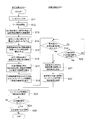
- FIG. 5 is a flowchart showing a flow of control executed by the work tool of FIG. 1 and an external terminal.
- FIG. 3 is a perspective view showing a configuration of a jigsaw as an example of the work tool of FIG.
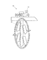
- FIG. 6 is a diagram schematically showing the movement of the saw blade when the output is increased by using an orbital in the jigsaw of FIG.
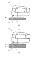
- FIG. (A) and (b) are views showing a state of cutting metal plates having different thicknesses using the jigsaw of FIG.
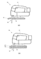
- FIG. (A) and (b) are views showing a state of cutting wooden boards having different thicknesses using the jigsaw of FIG.
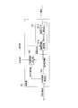
- FIG. 1 is a block diagram showing a configuration of a control system 100 including the work tool 10 of the present embodiment.
- the control system 100 of the present embodiment includes a work tool 10 and an external terminal 20.
- the work tool 10 is a tool driven by a motor 111 such as a jigsaw, a chainsaw, or an electric screwdriver.
- the external terminal 20 displays, for example, log data of control values related to the drive of the motor 111 mounted on the work tool 10, and sets constraint conditions for subsequent control.
- the work tool 10 is a kind of power consuming body on which the motor 111 is mounted, and as shown in FIG. 1, the mechanism unit 11, the input unit 12, the control unit 13, the log output unit 14, and the power supply unit 15 And a measuring unit 16.
- the mechanism unit 11 drives a saw blade or the like.
- the input unit 12 transmits the values detected by various sensors provided on the work tool 10 to the control unit 13.
- the control unit 13 controls the drive of the mechanism unit 11 including the motor 111 based on the input information from the input unit 12.
- the log output unit 14 transmits data such as log data of control values during driving and estimated work time measured by the measurement unit 16 to the external terminal 20.
- the power supply unit 15 supplies electric power to the mechanism unit 11, the input unit 12, the control unit 13, the log output unit 14, and the measurement unit 16.
- the mechanism unit 11 includes a motor 111, a speed reducer 112, an output unit 113, a position detection unit 114, and an output increase mechanism 115.
- the motor 111 is rotationally driven based on an instruction from the control unit 13.
- the motor 111 for example, a three-phase DC brushless motor can be used.
- the speed reducer 112 is composed of a gear mechanism or the like, and amplifies the torque of the motor 111. The rotation is synchronized between the speed reducer 112 and the motor 111, and the rotation of the motor 111 is decelerated and transmitted to the output unit 113.
- the output unit 113 is, for example, a jigsaw saw blade or the like, and converts the output of the motor 111 into mechanical work according to a purpose such as cutting.
- the rotation is synchronized between the speed reducer 112 and the output unit 113, and the rotation of the motor 111 is output.
- the position detection unit 114 is a magnetic sensor or the like represented by a Hall IC.
- the position detection unit 114 detects the rotation angle position of the motor 111 and transmits it to the control unit 13.
- the position detection unit 114 may be configured without using a sensor, and detects the rotation angle position of the motor 111 by detecting the current.
- the rotation is synchronized between the position detection unit 114 and the motor 111.
- the output increasing mechanism 115 is, for example, an orbital mounted near the saw blade when the work tool 10 is a jigsaw, an impact hammer mounted near the tip when the work tool 10 is an electric screwdriver, or the like.
- the mechanical output of the work tool 10 is increased in terms of the mechanism.
- the input unit 12 includes a trigger switch 121 and a sensor circuit 122.
- the trigger switch 121 is an analog switch, which is provided on the handle portion of the work tool 10, and adjusts the output of the motor 111 according to the pulling amount (operation amount) thereof. Further, when the trigger switch 121 is operated by the user, the trigger switch 121 transmits a signal indicating the start of measurement to the measurement unit 16.
- the sensor circuit 122 transmits the input pull amount of the trigger switch 121 to the control unit 13 via the log output unit 14.
- the sensor circuit 122 includes a pulling amount sensor 122a, a voltage sensor 122b, a current sensor 122c, a torque sensor 122d, and a temperature sensor 122e.
- the pull amount sensor 122a detects the pull amount (operation amount) of the trigger switch 121.
- the voltage sensor 122b detects the voltage applied to the motor 111.
- the current sensor 122c detects the current flowing through the motor 111.
- the torque sensor 122d detects the torque generated when the motor 111 rotates when, for example, the work tool 10 is used to perform bolting work on a predetermined material.
- the temperature sensor 122e detects the temperature of the motor 111 and the like.
- the sensor circuit 122 may include a sensor other than these sensors, for example, a sensor (humidity sensor) for measuring the ambient environment.
- Control unit 13 As shown in FIG. 1, the control unit 13 controls the drive of the mechanism unit 11 based on the constraint conditions set by the external terminal 20 capable of communicating with the work tool 10.
- the control unit 13 includes a feedback control unit 131, a motor drive circuit 132, a rotation speed calculation unit 133, and an output increase control unit 134.
- the feedback control unit 131 receives various sensor information input from the sensor circuit 122 and a rotation speed under the constraint condition received from the external terminal 20 according to the pull amount (operation amount) of the trigger switch 121 by the user.
- the output of the PWM (Pulse Width Modulation) signal is determined based on the rotation angle position and the rotation speed input from the calculation unit 133.
- the constraint conditions are a target value (fixed value), a vertical value limiter, a target value table, a sequence operation, and the like, which are set in the external terminal 20 described later and transmitted to the work tool 10. Then, the feedback control unit 131 transmits a PWM signal to the motor drive circuit 132.
- the PWM signal transmitted from the feedback control unit 131 is determined according to the pulling amount of the trigger switch 121 and the like, and is, for example, 90%, 50%, 10%, and the like. As a result, the output of the motor can be adjusted according to the pulling amount of the trigger switch 121 and the like. Further, in the work tool 10 of the present embodiment, the feedback control unit 131 sets the estimated work time received from the measurement unit 16 via the log output unit 14 and the target work time received from the setting unit 22 of the external terminal 20. In comparison, when the estimated work time is later than the target work time, the output increase control for increasing the output of the motor 111 is performed.
- the feedback control unit 131 increases the output of the motor 111 so that the work end time approaches the target work time.
- the output increase control unit 134 causes advance angle control or 150-degree energization method control. Since the advance angle control and the 150-degree energization method control are known controls for increasing the torque of the motor 111, detailed description thereof will be omitted here.
- the output increase control of the motor 111 general PWM control may be combined and performed. Further, when the estimated work time is later than the target work time, the feedback control unit 131 increases the output of the motor 111 on the mechanical surface so that the work completion time approaches the target work time.
- the feedback control unit 131 increases the output of the motor 111 so that the work end time approaches the target work time.
- Orbital, impact hammer, etc. are used by the output increasing mechanism 115 of the mechanism unit 11.
- any one may be selected and implemented according to the delay of the estimated working time with respect to the target working time. The means may be combined and carried out.
- the motor drive circuit 132 performs a commutation operation according to the rotation angle position detected by the position detection unit 114 of the mechanism unit 11, and the motor 111 is based on the ON duty ratio by the PWM signal input from the feedback control unit 131. The average voltage applied to the UVW phase of is switched.
- the rotation speed calculation unit 133 calculates the rotation speed of the motor 111 from the output pulse interval detected by the position detection unit 114 of the mechanism unit 11. Then, the rotation speed calculation unit 133 transmits the rotation angle position input from the position detection unit 114 and the calculated rotation speed to the feedback control unit 131 and the measurement unit 16, respectively.
- the output increase control unit 134 controls so as to increase the output of the motor 111 from the control surface based on the output increase setting input from the feedback control unit 131. Specifically, the output increase control unit 134 increases the output of the motor 111 by transmitting an output increase control signal to the motor drive circuit 132 so as to perform advance angle control, 150-degree energization method control, and the like. ..
- the log output unit 14 transmits data of various control amounts and an estimated work time described later to the feedback control unit 131.
- the various control amounts include a target value (for example, rotation speed), an output value (for example, duty ratio), and a sensor value (detection value of various sensors described above, for example, a trigger pull amount).
- the log output unit 14 contains the values of various sensors detected by the sensor circuit 122, the PWM output determined by the feedback control unit 131, the rotation position / rotation speed calculated by the rotation speed calculation unit 133, and the position detection unit 114.
- Various data such as the rotation angle position detected in 1 and the estimated working time estimated by the measuring unit 16 are input.
- the power supply unit 15 supplies electric power to the mechanism unit 11, the input unit 12, the control unit 13, the log output unit 14, and the measurement unit 16.
- the power supply unit 15 has a battery 151 and a battery control unit 152.
- the battery 151 is a replaceable secondary battery, and for example, an 18 V lithium ion battery or the like is used.
- the battery control unit 152 is an electronic circuit for charging / discharging a battery 151 such as a lithium ion battery.
- the measuring unit 16 receives the motor current, the rotation speed of the motor 111, the measurement start signal of the trigger switch 121, and the like, and the magnitude of the load applied to the motor 111 and the time until the predetermined work is completed. Estimate the estimated work time required. More specifically, as shown in FIG. 2, the measuring unit 16 has a load estimating unit 161, a working time measuring unit 162, and a working time estimating unit 163.
- the load estimation unit 161 calculates the load (estimated load information) applied to the motor 111 based on the motor current input to the motor 111 and the rotation speed of the motor 111. As shown in FIG. 2, the load estimation unit 161 has a load torque calculation unit 161a and a speed fluctuation analysis unit 161b. As shown in FIG. 2, the load torque calculation unit 161a receives the motor current transmitted from the motor drive circuit 132 according to the operation amount of the trigger switch 121, calculates the load torque of the motor 111, and analyzes the speed fluctuation. It is transmitted to unit 161b.
- the speed fluctuation analysis unit 161b analyzes the fluctuation of the rotation speed of the motor 111 based on the rotation speed of the motor 111 with respect to the load torque calculated by the load torque calculation unit 161a. Then, the speed fluctuation analysis unit 161b estimates the magnitude of the load applied to the motor 111 (estimated load information) based on the analysis result, and transmits it to the work time estimation unit 163.
- the working time measuring unit 162 first changes the measurement start signal indicating that the trigger switch 121 has been operated and the rotational speed (load torque) of the motor 111 received from the speed fluctuation analysis unit 161b. Is detected as the work start timing. Then, the work time measurement unit 162 measures the elapsed work time from the start of the work and transmits it to the work time estimation unit 163. As shown in FIG. 2, the work time estimation unit 163 is currently based on the estimated load information received from the load estimation unit 161 (speed fluctuation analysis unit 161b) and the elapsed work time received from the work time measurement unit 162. The time required to complete a predetermined work in progress is estimated, and the estimated work time is transmitted to the log output unit 14.
- the magnitude of the load applied to the motor 111 is based on the load torque calculated based on the motor current of the motor 111 and the rotation speed of the motor 111. Information) is calculated. Thereby, for example, the time required to complete the work currently in progress can be estimated using the estimated load information related to the motor 111. Further, it is confirmed how much the progress is with respect to the preset target work time for the predetermined work currently in progress, and if it is behind the target work time, for example, the motor 111. Controls such as increasing the output can be performed. Further, the estimated load information can be used to estimate the skill level (proficiency level) of the user who is currently working.
- the external terminal 20 is a terminal used by a user or an administrator (for example, a PC (Personal Computer) capable of communicating with the work tool 10), and the constraint conditions of the work tool 10 are set and the work tool 10 side. Is transmitted to the control unit 13. More specifically, as shown in FIG. 1, the external terminal 20 has a display unit 21, a setting unit 22, and a communication unit 23.
- a PC Personal Computer
- the display unit 21 is, for example, a display device having an input function such as a liquid crystal touch panel, and is a reference time (target work time) required to complete the work and incidental work information for each work using the work tool 10. Etc. are input.
- the target work time is, for example, a reference time required for cutting 100 wooden boards having a thickness of 20 mm and a size of 50 cm ⁇ 50 cm in a cutting work using a jigsaw as a work tool 10.
- the incidental work information includes, for example, information such as the number of operations and the screw depth (length) used in the screw tightening operation using the electric screwdriver as the work tool 10.
- the display unit 21 transmits the input target work time and incidental work information to the setting unit.
- the setting unit 22 generates a constraint condition for a predetermined control value of the motor 111 with reference to the target work time and incidental work information input via the display unit 21, and the work tool 10 Is transmitted to the feedback control unit 131 of.
- the communication unit 23 transmits the constraint conditions, target work time, and incidental work information of the motor 111 set in the setting unit 22 to the central management terminal (management device) 30 used by the administrator. To do. Then, the communication unit 23 receives various information such as the constraint conditions of the motor 111, the target work time, and the incidental work information input to the central management terminal 30 by the administrator from the central management terminal 30, and the setting unit 22 receives it. Send to. As a result, if necessary, the central management terminal 30 managed by the administrator can also input the constraint conditions of the motor 111, the target working time, and the like and transmit them to the feedback control unit 131 of the work tool 10.
- the work tool 10 of the present embodiment includes a plurality of output increasing means for increasing the output of the motor 111 when the estimated work time is delayed from the target work time.
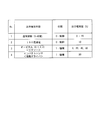
- the output increasing means of the work tool 10 by the output increasing control unit 134 and the output increasing mechanism 115 shown in FIG. 1 will be described with reference to FIG. That is, as a means for increasing the output of the work tool 10, as shown in FIG. 3, output increase control by motor control and mechanical means can be considered.
- the output increasing means table shown in FIG. 3 is, for example, preferentially selected in order from No. 1, and may be adopted in a stacking method in order from the one having the higher rank.
- the output increasing means by the motor control includes, for example, advance angle control (0 to 40 degrees), control by a 150 degree energization method, and the like. These advance angle control and 150 degree energization method control are performed by the output increase control unit 134 shown in FIG.
- the advance angle control is a control that maximizes the torque by matching the phase between the induced voltage of the motor and the winding current, and the amount of increase in output when the advance angle control is performed is as shown in FIG. It is about 0 to 20%.
- the 150-degree energization method control is a control by a sine wave energization method adopted as a control method for a three-phase brushless motor, and the amount of increase in output when the 150-degree energization method control is performed is as shown in FIG. It is about 10%.
- the mechanical output increasing means for example, as shown in FIG. 3, an orbital when the work tool 10 is a jigsaw, an impact hammer when the work tool 10 is an electric screwdriver, or the like can be considered.
- the output increase amount of the jigsaw combined with the orbital can be switched between 0, 20, 40, and 60% by a dial operation that can be selected stepwise.
- the output increase amount of the electric screwdriver combined with the impact hammer is 80%.
- a control surface and a mechanical output increasing means for increasing the output of the motor 111 are adopted.
- the user can adopt the output increase control or the output increase mechanism so that the work tool 10 automatically increases the output of the motor 111 without taking measures to increase the output of the motor 111. Therefore, even if there is a difference in the skill level of the user, the work can be completed in a work time close to the target work time, so that the work process of various works using the work tool 10 can be carried out as planned. it can. As a result, the management burden on the administrator can be reduced.
- the work tool 10 of the present embodiment has the above configuration, and processes from the operation of the trigger switch 121 to the setting of the constraint condition for the control of the work tool 10 are performed according to the flowchart shown in FIG.
- steps S11 to S18 and S23 to S25 show the processing on the work tool 10 side
- steps S19 to S22 show the processing on the external terminal 20 side.
- step S11 the trigger switch 121 is operated by the user, and the trigger switch 121 shifts from the OFF state to the ON state. At this time, the pull amount (operation amount) of the trigger switch 121 is transmitted to the pull amount sensor 122a.
- step S12 the rotation of the motor 111 is started according to the pulling amount of the trigger switch 121 in step S11.
- the output from the pull amount sensor 122a is transmitted to the feedback control unit 131 via the log output unit 14. Then, the feedback control unit 131 transmits the PWM output to the motor drive circuit 132 according to the set constraint condition and the pull amount of the trigger switch 121 output from the pull amount sensor 122a. As a result, the motor drive circuit 132 can control the rotation of the motor 111 according to the constraint condition and the pulling amount of the trigger switch 121.
- step S13 the rotation speed calculation unit 133 of the control unit 13 receives the signal from the position detection unit 114 of the mechanism unit 11 and starts the calculation of the rotation speed of the motor 111.
- step S14 the load torque calculation unit 161a of the load estimation unit 161 of the measurement unit 16 calculates the load torque based on the motor current.
- step S15 the speed fluctuation analysis unit 161b of the load estimation unit 161 creates estimated load information based on the rotation speed of the motor 111 and the load torque.
- step S16 the work time measuring unit 162 starts a predetermined work based on the measurement start signal at which the operation of the trigger switch 121 is started and the timing of the load fluctuation detected by the load estimation unit 161. Start measuring the elapsed work time, which indicates the elapsed time since it was done. As a result, after operating the trigger switch 121 of the work tool 10 to rotate the motor 111, the timing at which the tip tool or the like comes into contact with the wooden board or the like to be worked and the load fluctuates is detected as the start of work. Subsequent measurement of working time can be started.
- step S17 the work time estimation unit 163 completes the predetermined work in progress based on the estimated load information received from the load estimation unit 161 and the elapsed work time received from the work time measurement unit 162. Estimate the time required to do this (estimated work time).
- step S18 the work time estimation unit 163 transmits the estimated work time to the feedback control unit 131 via the log output unit 14.
- step S19 it is determined on the external terminal 20 side whether or not the target work time and incidental work information have been input via the display unit 21.
- step S21 if it is input, the process proceeds to step S21, and if it is not input, the process proceeds to step S20.
- step S20 it is determined whether or not the target work time and incidental work information have been input from the central management terminal 30, although there is no input from the display unit 21.
- step S21 the setting unit 22 of the external terminal 20 generates the constraint condition of the motor 111 from the target work time and incidental work information input from the display unit 21 and the like.
- step S22 the setting unit 22 of the external terminal 20 transmits the constraint condition of the motor 111, the target work time, and the accompanying work information to the feedback control unit 131 on the work tool 10 side.
- step S23 the feedback control unit 131 on the work tool 10 side registers new constraint conditions and the like received from the setting unit 22 on the external terminal 20 side.
- step S24 for example, using a display screen or the like provided on the work tool 10 side, a control surface (advance angle control, 150 degree energization method control, etc.) or a mechanical surface (orbital, impact hammer, etc.) can be used. Confirm with the user whether or not to set the output increase of the motor 111.
- the desired output increase means is selected in step S25, and the process ends.
- the output increasing control unit 134 executes the output increasing control (advance angle control, 150 degree energization method control, etc.).
- the output increasing means in terms of mechanism is selected, for example, it is controlled to display a display prompting the user to use the orbital and set the stage.
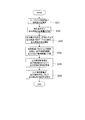
- the work tool 10 of the present embodiment has the above configuration, and is mounted on the work tool 10 based on the constraint conditions set or changed on the external terminal 20 side according to the flowchart shown in FIG. Feedback control of the motor 111 is performed.
- step 31 the feedback control unit 131 confirms the constraint condition received from the external terminal 20.
- step S32 the feedback control unit 131 calculates the required amount of increase in the motor output based on the constraint conditions received in step S31.
- step S33 the feedback control unit 131 refers to the output increasing means table (see FIG. 3) so as to satisfy the output increasing setting calculated in step S32, and selects the output increasing means.
- the output increase setting is information summarizing the selected output increase means and the setting (intensity or ON / OFF).
- the process of selecting the output increasing means from the output increasing means table shown in FIG. 3 may be performed by the control unit 13 of the work tool 10, or the output increasing means table may be presented to the user or the like for selection. May be urged to.
- step S34 the feedback control unit 131 transmits to the output increase control unit 134 and the output increase mechanism 115 so as to execute the output increase setting according to the selection result in step S33.
- step S35 the output increase control unit 134 executes output increase control (advance angle control, 150-degree energization method control, etc.) based on the output increase setting received from the feedback control unit 131.
- step S36 the output increasing mechanism 115 performs an operation using an output increasing means (orbital, impact hammer, etc.) based on the output increasing setting received from the feedback control unit 131.
- the jigsaw 50 is a work tool for cutting wood and metal by reciprocating the saw blade 52 in the vertical direction at high speed, and as shown in FIG. 6, the main body 51, the saw blade 52, and the orbital ( It is equipped with an output increasing mechanism) 53.
- the reciprocating movement of the saw blade 52 in the vertical direction means the reciprocating movement in the vertical direction in FIG. 7 in the direction of advancing and retreating with respect to the main body 51.
- the main body 51 has a built-in configuration (for example, motor 111, battery 151, etc.) shown in FIG. 1, and the saw blade rotates at a speed corresponding to the pulling amount of the trigger switch 121.
- the 52 is reciprocated up and down.
- the saw blade 52 is a tip tool attached to the tip of the mechanical portion 11, and is attached so as to project downward from the main body portion 51.
- the orbital 53 is arranged in contact with the root portion of the saw blade 52 close to the attachment portion of the saw blade 52 to the main body 51. Then, when the orbital 53 reciprocates in the vertical direction of the saw blade 52, the saw blade 52 is moved in the direction in which the blade is present so that the tip portion of the saw blade 52 moves on the elliptical orbit in the side view shown in FIG. It is a mechanism that pushes out in stages.
- the pressing amount of the saw blade 52 by the orbital 53 is configured to be set in, for example, four steps.
- the stepwise setting is performed by a switching drive unit (motor, solenoid, etc.) (not shown).
- the setting of the orbital 53 can be changed stepwise to carry out the work in consideration of the hardness of the material to be cut by the jigsaw 50, the working speed, and the like.
- the thickness of the metal plate is different.
- the motor load current (load torque) applied to the motor 111 of the work tool 10 is also doubled.
- the thickness of the wooden board is doubled.
- the motor load current (load torque) applied to the motor 111 of the work tool 10 is also doubled.
- the working time of the cutting work is shortened, while the load current (load torque) is increased as well as the thickness of the material to be cut is increased. ..
- the target work time set in the external terminal 20 or the like and the estimated work time of the work currently in progress are compared, and for example, the work in progress can be performed. If there is a delay, the output increasing means on the control surface and the mechanical surface that increase the output of the motor 111 is adopted.
- the orbital 53 shown in FIG. 7 is controlled to operate.
- the orbital 53 can be set in four stages of 0 to 3, it may be controlled so as to be set in an appropriate stage according to the degree of delay from the target working time, or the user may be asked. A display prompting you to select a stage may be provided.
- the user can adopt the output increase control or the output increase mechanism so that the work tool 10 automatically increases the output of the motor 111 without taking measures to increase the output of the motor 111. Therefore, even if there is a difference in the skill level of the user, the work can be completed in a work time close to the target work time, so that the work process of various works using the work tool 10 can be carried out as planned. it can. As a result, the management burden on the administrator can be reduced.
- the load estimation unit 161 uses the estimated load information created based on the motor current and the rotation speed of the motor 111 to complete the predetermined work currently in progress (estimated work time). The explanation was given with an example used for the estimation of. However, the present invention is not limited to this.
- the estimated load information created by the load estimation unit 161 may be used, for example, for estimating the skill level of the user during work.
- the estimated work time estimated from the actual work situation is compared with the target work time, and when a delay occurs, the output of the motor 111 is increased so as to approach the target work time.
- An example of adopting various means has been described. However, the present invention is not limited to this.
- the delay of the work time may be displayed on the display unit of the external terminal or the like.
- the user or administrator who has confirmed the display unit of the external terminal recognizes the delay in the work and takes measures such as increasing the number of workers, thereby causing a delay in the work process. It can be avoided.
- the work tool 10 is connected to the external terminal 20, and the target work time, the constraint conditions, etc. input to the external terminal 20 are transmitted to the work tool 10 side.
- the present invention is not limited to this.
- constraint conditions and target work time may be set on the work tool side. That is, the present invention may be configured by a single work tool that does not include an external terminal.
- the central management terminal 30 used by the administrator is connected to the work tool 10 via the external terminal 20 .
- the present invention is not limited to this.
- the central management terminal may be configured as a control system connected to a work tool.
- control target may be a power consumer equipped with another motor such as a brushed DC motor.
- the jigsaw 50 has been mainly described as an example of the work tool of the present invention.
- the present invention is not limited to this.
- the present invention may be applied to other work tools such as an electric screwdriver and a chainsaw.
- the work tool of the present invention has the effect of being able to estimate the load applied to the motor with high accuracy, it can be widely applied to various work tools equipped with a motor.
Landscapes
- Engineering & Computer Science (AREA)
- Life Sciences & Earth Sciences (AREA)
- Mechanical Engineering (AREA)
- Wood Science & Technology (AREA)
- Forests & Forestry (AREA)
- Power Engineering (AREA)
- Physics & Mathematics (AREA)
- Electromagnetism (AREA)
- Sawing (AREA)
- Control Of Electric Motors In General (AREA)
- Control Of Motors That Do Not Use Commutators (AREA)
- Portable Power Tools In General (AREA)
Abstract
作業工具(10)は、モータ(111)と、トリガスイッチ(121)と、測定部(16)(負荷推定部(161))と、を備えている。トリガスイッチ(121)は、操作者によって操作され、操作量に応じてモータ(111)の出力を調整する。測定部(16)は、モータ(111)に入力されるモータ電流と、モータ(111)の回転速度と、に基づいて、モータ(111)に掛かる推定負荷情報を算出する。
Description
本発明は、例えば、電動ドライバ、ジグソー、チェーンソー等のモータを備えた作業工具およびこれを備えた制御システムに関する。
作業現場や工場において、ドリルやドライバなどの先端工具をモータによって回転駆動して所望の作業を行う電動工具が広く用いられている(例えば、特許文献1参照。)。
しかしながら、上記従来の作業工具では、以下に示すような問題点を有している。
すなわち、一般的に、電動ドライバ、ジグソー、チェーンソー等の作業工具を使用する際には、使用者のスキル(力のかけ方)によって、熟練者とそれ以外の人とで作業完了までに要する時間に大きな差が生じる。また、作業対象(例れば、木材、金属等)によっても、作業量が大幅に異なる。
すなわち、一般的に、電動ドライバ、ジグソー、チェーンソー等の作業工具を使用する際には、使用者のスキル(力のかけ方)によって、熟練者とそれ以外の人とで作業完了までに要する時間に大きな差が生じる。また、作業対象(例れば、木材、金属等)によっても、作業量が大幅に異なる。
このため、例えば、所定の作業を完了するまでに要する目標作業時間と実際の作業時間との差を正確に把握するためには、モータに掛かる負荷を正確に推定することが要求される。
本発明の課題は、モータに掛かる負荷を高精度に推定することが可能な作業工具およびこれを備えた制御システムを提供することにある。
本発明の課題は、モータに掛かる負荷を高精度に推定することが可能な作業工具およびこれを備えた制御システムを提供することにある。
第1の発明に係る作業工具は、モータと、トリガスイッチと、負荷推定部と、を備えている。トリガスイッチは、使用者によって操作され、操作量に応じてモータの出力を調整する。負荷推定部は、モータに入力されるモータ電流と、モータの回転速度と、に基づいて、モータに掛かる推定負荷情報を算出する。
ここでは、トリガスイッチの操作によって駆動されるモータを搭載した作業工具において、モータ電流と回転速度とに基づいて、モータに掛かる負荷の大きさ(推定負荷情報)を推定する。
ここでは、トリガスイッチの操作によって駆動されるモータを搭載した作業工具において、モータ電流と回転速度とに基づいて、モータに掛かる負荷の大きさ(推定負荷情報)を推定する。
ここで、作業工具には、例えば、電動ドライバ、ジグソー、チェーンソー等のモータによって駆動される各種工具が含まれる。そして、作業工具を用いて行われる所定の作業には、電動ドライバを用いたネジ締め・外し作業、ボルト締め・外し作業、ジグソーを用いた切削作業、チェーンソーを用いた切削作業等が含まれる。
これにより、モータを搭載した作業工具を使用する際に、モータに掛かる負荷を推定することで、例えば、所定の作業を完了するまでに要する目標作業時間に対する実際の作業時間の遅れ等を、使用者あるいは管理者に認識させることができる。また、その目標作業時間に対する実際の作業時間の遅れを解消するために、例えば、モータの出力を増加させる制御を実施することができる。さらに、モータに掛かる負荷に基づいて、使用者の熟練度を推定することもできる。
これにより、モータを搭載した作業工具を使用する際に、モータに掛かる負荷を推定することで、例えば、所定の作業を完了するまでに要する目標作業時間に対する実際の作業時間の遅れ等を、使用者あるいは管理者に認識させることができる。また、その目標作業時間に対する実際の作業時間の遅れを解消するために、例えば、モータの出力を増加させる制御を実施することができる。さらに、モータに掛かる負荷に基づいて、使用者の熟練度を推定することもできる。
第2の発明に係る作業工具は、第1の発明に係る作業工具であって、負荷推定部は、負荷トルク算出部と、速度変動解析部と、を有している。負荷トルク算出部は、モータ電流に基づいて負荷トルクを算出する。速度変動解析部は、負荷トルク算出部において算出された負荷トルクに対するモータの回転速度の変動を解析して推定負荷情報を出力する。
ここでは、モータ電流に基づいて算出された負荷トルクと、負荷トルクに対するモータの回転速度の変動を解析して、モータに掛かる負荷を推定する。
これにより、推定された負荷情報を用いて、例えば、目標作業時間の調整、目標作業時間に間に合わせるためのモータ出力増加制御等を実施することができる。
ここでは、モータ電流に基づいて算出された負荷トルクと、負荷トルクに対するモータの回転速度の変動を解析して、モータに掛かる負荷を推定する。
これにより、推定された負荷情報を用いて、例えば、目標作業時間の調整、目標作業時間に間に合わせるためのモータ出力増加制御等を実施することができる。
第3の発明に係る作業工具は、第1または第2の発明に係る作業工具であって、トリガスイッチが操作されてからモータの負荷変動が発生した作業開始時間からの経過作業時間を計測する作業時間測定部を、さらに備えている。
ここでは、トリガスイッチが操作されてからモータの負荷変動が発生した作業開始時間を検知して、作業開始からの経過作業時間を計測する。
これにより、目標作業時間と実際の経過作業時間とを比較することで、目標作業時間に対して、実際の作業がどの程度遅れているかを、使用者あるいは管理者等に認識させることができる。
これにより、目標作業時間と実際の経過作業時間とを比較することで、目標作業時間に対して、実際の作業がどの程度遅れているかを、使用者あるいは管理者等に認識させることができる。
第4の発明に係る作業工具は、第3の発明に係る作業工具であって、負荷推定部から受信した推定負荷情報と、作業時間測定部から受信した経過作業時間とに基づいて、所定の作業を完了するまでに必要な推定作業時間を推定する作業時間推定部を、さらに備えている。
ここでは、推定された負荷情報と、所定の作業を開始してからの経過時間を示す経過作業時間とに基づいて、このまま作業を継続した場合に作業が終了するまでに要する推定作業時間を推定する。
ここでは、推定された負荷情報と、所定の作業を開始してからの経過時間を示す経過作業時間とに基づいて、このまま作業を継続した場合に作業が終了するまでに要する推定作業時間を推定する。
これにより、現在作業中の使用者が、いつ作業が完了するのかを認識することができるため、例えば、目標作業時間からの遅れを解消するための措置として、モータの出力増加手段(制御面および機構面)等を採用することができる。
さらに、現在作業中の使用者が、目標作業時間に対してどの程度の遅れがあるのかを把握することで、例えば、その使用者の作業工具を扱う技量レベル(熟練度)を判定することもできる。
さらに、現在作業中の使用者が、目標作業時間に対してどの程度の遅れがあるのかを把握することで、例えば、その使用者の作業工具を扱う技量レベル(熟練度)を判定することもできる。
第5の発明に係る作業工具は、第1から第4の発明のいずれか1つに係る作業工具であって、作業時間推定部から受信した推定作業時間と、予め設定された目標作業時間とを比較して、作業時間が目標作業時間に近づくように、モータの出力を増加させるように制御を行うフィードバック制御部を、さらに備えている。
ここでは、フィードバック制御部が、今までに掛かった作業時間と目標作業時間とを参照して、例えば、PWM(Pulse Width Modulation)制御等の出力増加制御、あるいはオービタルやインパクトハンマ等の出力増加機構を用いて、モータの出力を増加させる。
ここでは、フィードバック制御部が、今までに掛かった作業時間と目標作業時間とを参照して、例えば、PWM(Pulse Width Modulation)制御等の出力増加制御、あるいはオービタルやインパクトハンマ等の出力増加機構を用いて、モータの出力を増加させる。
なお、これらのモータ出力を増加させる制御は、単独で採用されてもよいし、複数の制御を組み合わせて採用されてもよい。
これにより、例えば、今までに掛かった作業時間が目標作業時間よりも遅い場合でも、モータの出力を増加させることで、使用者等によって予め設定された所定の作業に対する目標作業時間に近づくように制御することができる。
これにより、例えば、今までに掛かった作業時間が目標作業時間よりも遅い場合でも、モータの出力を増加させることで、使用者等によって予め設定された所定の作業に対する目標作業時間に近づくように制御することができる。
第6の発明に係る作業工具は、第5の発明に係る作業工具であって、フィードバック制御部は、出力増加制御および出力増加機構のうちの少なくとも一方を選択して、モータの出力を増加させる制御を行う。
ここでは、制御面あるいは機構面における複数の出力増加手段の少なくとも1つを選択して、モータの出力を増加させる。
これにより、制御面または機構面からモータの出力を増加させることで、例えば、今までに掛かった作業時間が目標作業時間よりも遅い場合でも、使用者等によって予め設定された所定の作業に対する目標作業時間に近づくように制御することができる。
ここでは、制御面あるいは機構面における複数の出力増加手段の少なくとも1つを選択して、モータの出力を増加させる。
これにより、制御面または機構面からモータの出力を増加させることで、例えば、今までに掛かった作業時間が目標作業時間よりも遅い場合でも、使用者等によって予め設定された所定の作業に対する目標作業時間に近づくように制御することができる。
第7の発明に係る作業工具は、第6の発明に係る作業工具であって、出力増加制御には、PWM(Pulse Width Modulation)制御、進角制御、150度通電方式制御のうちの少なくとも1つが含まれる。
ここでは、上述したモータ出力増加制御として、PWM制御、進角制御、150度通電方式制御のうちの少なくとも1つを実施する。
これにより、これらのモータ制御を選択して、あるいは組み合わせて、モータの出力を増加させることができる。
ここでは、上述したモータ出力増加制御として、PWM制御、進角制御、150度通電方式制御のうちの少なくとも1つを実施する。
これにより、これらのモータ制御を選択して、あるいは組み合わせて、モータの出力を増加させることができる。
第8の発明に係る作業工具は、第6または第7の発明に係る作業工具であって、出力増加機構には、オービタルあるいはインパクトハンマが含まれる。
ここでは、例えば、ジグソー等の作業工具の機械出力増加機構として用いられるオービタル、あるいは電動ドライバ等の作業工具の機械出力増加機構として用いられるインパクトハンマによって、作業工具の機械出力を増加させる。
これにより、各種作業工具の機械出力を、機構的な側面から増加させることができる。
ここでは、例えば、ジグソー等の作業工具の機械出力増加機構として用いられるオービタル、あるいは電動ドライバ等の作業工具の機械出力増加機構として用いられるインパクトハンマによって、作業工具の機械出力を増加させる。
これにより、各種作業工具の機械出力を、機構的な側面から増加させることができる。
第9の発明に係る作業工具は、第1から第8の発明のいずれか1つに係る作業工具であって、モータの制御に関する値を検出するセンサを、さらに備えている。
これにより、モータの制御に関する各種データを、各種センサを用いて取得することができる。
これにより、モータの制御に関する各種データを、各種センサを用いて取得することができる。
第10の発明に係る作業工具は、第9の発明に係る作業工具であって、センサは、トリガスイッチの操作量を検出するセンサ、モータに印加される電圧を検出する電圧センサ、モータに流れる電流を検出する電流センサ、モータの温度を検出する温度センサを含む。
これにより、トリガスイッチの操作量を検出するセンサ、モータの電圧センサ、電流センサ、温度センサ等における検出結果を取得することができる。
これにより、トリガスイッチの操作量を検出するセンサ、モータの電圧センサ、電流センサ、温度センサ等における検出結果を取得することができる。
第11の発明に係る作業工具は、第1から第10の発明のいずれか1つに係る作業工具であって、モータは、ブラシレスモータである。
これにより、長寿命で小型化が可能であり高出力、高効率という特徴を持つブラシレスモータを備え、使用者にとって使い勝手よい作業工具を提供することができる。
これにより、長寿命で小型化が可能であり高出力、高効率という特徴を持つブラシレスモータを備え、使用者にとって使い勝手よい作業工具を提供することができる。
第12の発明に係る制御システムは、第1から第11の発明のいずれか1つに係る作業工具と、作業工具に対して送信されるモータに対する制約条件を設定する外部端末と、を備えている。
ここでは、上述した作業工具と外部端末とを組み合わせて、制御システムを構成する。
ここで、外部端末には、使用者や管理者が使用するPC(Personal Computer)、タブレット端末、スマートフォン等が含まれる。
これにより、作業工具に対して、作業工具に搭載されたモータに対する制約条件を設定して、送信することができる。
ここでは、上述した作業工具と外部端末とを組み合わせて、制御システムを構成する。
ここで、外部端末には、使用者や管理者が使用するPC(Personal Computer)、タブレット端末、スマートフォン等が含まれる。
これにより、作業工具に対して、作業工具に搭載されたモータに対する制約条件を設定して、送信することができる。
第13の発明に係る制御システムは、第12の発明に係る制御システムであって、外部端末は、制約条件と予め設定される目標作業時間とを設定する設定部を有している。
ここでは、外部端末側に設けられた設定部において、制約条件と予め設定される目標作業時間とを設定する。
これにより、制約条件とともに、所定の作業に関する目標作業時間を設定して、作業工具へ送信することができる。
ここでは、外部端末側に設けられた設定部において、制約条件と予め設定される目標作業時間とを設定する。
これにより、制約条件とともに、所定の作業に関する目標作業時間を設定して、作業工具へ送信することができる。
第14の発明に係る制御システムは、第13の発明に係る制御システムであって、外部端末は、目標作業時間とモータの出力を増加させる出力増加情報とを管理装置へ送信する通信部を、さらに有している。
ここでは、使用者等が使用するPCやタブレット端末、スマートフォン等の外部端末の通信部を介して、目標作業時間とモータの出力を増加させる出力増加情報とが、管理者が使用する管理装置へ送信される。
これにより、管理者は、管理装置において受信した目標作業時間と出力増加情報とを参照して、例えば、目標作業時間の達成状況、使用者の習熟度の変化等を確認することができる。
これにより、管理者は、管理装置において受信した目標作業時間と出力増加情報とを参照して、例えば、目標作業時間の達成状況、使用者の習熟度の変化等を確認することができる。
第15の発明に係る制御システムは、第14の発明に係る制御システムであって、通信部から、目標作業時間とモータの出力を増加させる出力増加情報とが送信される管理装置を、さらに備えている。
ここでは、本制御システムが、外部端末から目標作業時間とモータの出力を増加させる出力増加情報とが送信される管理装置を含むように構成される。
ここでは、本制御システムが、外部端末から目標作業時間とモータの出力を増加させる出力増加情報とが送信される管理装置を含むように構成される。
これにより、管理者は、制御システムに含まれる管理装置において受信した目標作業時間と出力増加情報とを参照して、例えば、目標作業時間の達成状況、使用者の習熟度の変化等を確認することができる。
(発明の効果)
本発明に係る作業工具によれば、モータに掛かる負荷を高精度に推定することができる。
本発明に係る作業工具によれば、モータに掛かる負荷を高精度に推定することができる。
本発明の一実施形態に係る作業工具10およびこれを備えた制御システム100について、図1~図9(b)を用いて説明すれば以下の通りである。
(制御システム100の概要)
図1は、本実施形態の作業工具10を含む制御システム100の構成を示すブロック図である。
本実施形態の制御システム100は、図1に示すように、作業工具10と、外部端末20と、を備えている。作業工具10は、例えば、ジグソー、チェーンソー、電動ドライバ等のモータ111によって駆動される工具である。外部端末20は、例えば、作業工具10に搭載されたモータ111の駆動に関する制御値のログデータ等を表示するとともに、その後の制御の制約条件等が設定される。
図1は、本実施形態の作業工具10を含む制御システム100の構成を示すブロック図である。
本実施形態の制御システム100は、図1に示すように、作業工具10と、外部端末20と、を備えている。作業工具10は、例えば、ジグソー、チェーンソー、電動ドライバ等のモータ111によって駆動される工具である。外部端末20は、例えば、作業工具10に搭載されたモータ111の駆動に関する制御値のログデータ等を表示するとともに、その後の制御の制約条件等が設定される。
(作業工具10)
作業工具10は、モータ111を搭載した電力消費体の一種であって、図1に示すように、機構部11と、入力部12と、制御部13と、ログ出力部14と、電源部15と、測定部16と、を備えている。
機構部11は、例えば、作業工具10がジグソーの場合、鋸刃などを駆動する。
作業工具10は、モータ111を搭載した電力消費体の一種であって、図1に示すように、機構部11と、入力部12と、制御部13と、ログ出力部14と、電源部15と、測定部16と、を備えている。
機構部11は、例えば、作業工具10がジグソーの場合、鋸刃などを駆動する。
入力部12は、作業工具10に設けられた各種センサによって検出された値を、制御部13へと送信する。
制御部13は、入力部12からの入力情報などに基づいて、モータ111を含む機構部11の駆動の制御を行う。
ログ出力部14は、駆動時における制御値のログデータ、測定部16において測定された推定作業時間等のデータを外部端末20に送信する。
電源部15は、機構部11、入力部12、制御部13、ログ出力部14および測定部16に対して、電力を供給する。
制御部13は、入力部12からの入力情報などに基づいて、モータ111を含む機構部11の駆動の制御を行う。
ログ出力部14は、駆動時における制御値のログデータ、測定部16において測定された推定作業時間等のデータを外部端末20に送信する。
電源部15は、機構部11、入力部12、制御部13、ログ出力部14および測定部16に対して、電力を供給する。
(機構部11)
機構部11は、図1に示すように、モータ111と、減速機112と、出力部113と、位置検出部114と、出力増加機構115と、を有している。
機構部11は、図1に示すように、モータ111と、減速機112と、出力部113と、位置検出部114と、出力増加機構115と、を有している。
モータ111は、制御部13からの指示に基づいて回転駆動される。モータ111としては、例えば、三相DCブラシレスモータを用いることができる。
減速機112は、ギア機構などによって構成されており、モータ111のトルクを増幅する。減速機112とモータ111との間は、回転の同期がとられており、モータ111の回転を減速して出力部113へと伝達する。
減速機112は、ギア機構などによって構成されており、モータ111のトルクを増幅する。減速機112とモータ111との間は、回転の同期がとられており、モータ111の回転を減速して出力部113へと伝達する。
出力部113は、例えば、ジグソーの鋸刃等であって、切断等の目的に応じてモータ111の出力を機械的な仕事に変換する。減速機112と出力部113との間は、回転の同期が取られており、モータ111の回転を出力する。
位置検出部114は、ホールICに代表される磁気センサ等である。位置検出部114は、モータ111の回転角度位置を検出し、制御部13へ送信する。位置検出部114は、センサを用いない構成であってもよく、電流を検出することによりモータ111の回転角度位置を検出する。位置検出部114とモータ111の間において回転の同期がとられている。
出力増加機構115は、例えば、作業工具10がジグソーである場合には、鋸刃付近に装着されるオービタル、作業工具10が電動ドライバである場合には、先端部付近に装着されるインパクトハンマ等を含む機構であって、それぞれ、作業工具10の機械出力を機構面において増加させる。
位置検出部114は、ホールICに代表される磁気センサ等である。位置検出部114は、モータ111の回転角度位置を検出し、制御部13へ送信する。位置検出部114は、センサを用いない構成であってもよく、電流を検出することによりモータ111の回転角度位置を検出する。位置検出部114とモータ111の間において回転の同期がとられている。
出力増加機構115は、例えば、作業工具10がジグソーである場合には、鋸刃付近に装着されるオービタル、作業工具10が電動ドライバである場合には、先端部付近に装着されるインパクトハンマ等を含む機構であって、それぞれ、作業工具10の機械出力を機構面において増加させる。
(入力部12)
入力部12は、図1に示すように、トリガスイッチ121と、センサ回路122と、を有している。
入力部12は、図1に示すように、トリガスイッチ121と、センサ回路122と、を有している。
トリガスイッチ121は、アナログスイッチであって、作業工具10の持ち手部分に設けられており、その引き量(操作量)に応じてモータ111の出力を調整する。また、トリガスイッチ121は、使用者によって操作されると、計測開始を示す信号を測定部16へ送信する。
センサ回路122は、入力されたトリガスイッチ121の引き量を、ログ出力部14を介して制御部13へと送信する。センサ回路122は、引き量センサ122aと、電圧センサ122bと、電流センサ122cと、トルクセンサ122dと、温度センサ122eとを含む。
センサ回路122は、入力されたトリガスイッチ121の引き量を、ログ出力部14を介して制御部13へと送信する。センサ回路122は、引き量センサ122aと、電圧センサ122bと、電流センサ122cと、トルクセンサ122dと、温度センサ122eとを含む。
引き量センサ122aは、トリガスイッチ121の引き量(操作量)を検出する。
電圧センサ122bは、モータ111への印加される電圧を検出する。
電流センサ122cは、モータ111に流れる電流を検出する。
トルクセンサ122dは、例えば、作業工具10を用いて所定の材料にボルト止め作業を実施する際に、モータ111の回転時に生じるトルクを検出する。
温度センサ122eは、モータ111等の温度を検出する。
なお、センサ回路122は、これらのセンサ以外のセンサ、例えば、周囲環境を計測するセンサ(湿度センサ)等を含んでいてもよい。
電圧センサ122bは、モータ111への印加される電圧を検出する。
電流センサ122cは、モータ111に流れる電流を検出する。
トルクセンサ122dは、例えば、作業工具10を用いて所定の材料にボルト止め作業を実施する際に、モータ111の回転時に生じるトルクを検出する。
温度センサ122eは、モータ111等の温度を検出する。
なお、センサ回路122は、これらのセンサ以外のセンサ、例えば、周囲環境を計測するセンサ(湿度センサ)等を含んでいてもよい。
(制御部13)
制御部13は、図1に示すように、作業工具10と通信可能な外部端末20によって設定された制約条件に基づいて、機構部11の駆動を制御する。制御部13は、フィードバック制御部131と、モータ駆動回路132と、回転速度演算部133と、出力増加制御部134と、を有している。
制御部13は、図1に示すように、作業工具10と通信可能な外部端末20によって設定された制約条件に基づいて、機構部11の駆動を制御する。制御部13は、フィードバック制御部131と、モータ駆動回路132と、回転速度演算部133と、出力増加制御部134と、を有している。
フィードバック制御部131は、使用者によるトリガスイッチ121の引き量(操作量)に応じて、外部端末20から受信した制約条件のもとで、センサ回路122から入力される各種センサ情報と、回転速度演算部133から入力される回転角度位置および回転速度とに基づいて、PWM(Pulse Width Modulation)信号の出力を決定する。
なお、制約条件とは、目標値(固定値)、上下値リミッタ、目標値テーブル、シーケンス動作などであって、後述する外部端末20において設定され、作業工具10へ送信される。そして、フィードバック制御部131は、モータ駆動回路132にPWM信号を送信する。
なお、制約条件とは、目標値(固定値)、上下値リミッタ、目標値テーブル、シーケンス動作などであって、後述する外部端末20において設定され、作業工具10へ送信される。そして、フィードバック制御部131は、モータ駆動回路132にPWM信号を送信する。
フィードバック制御部131から送信されるPWM信号は、トリガスイッチ121の引き量等に応じて決定され、例えば、90%、50%、10%等である。これにより、トリガスイッチ121の引き量等に応じて、モータの出力を調整することができる。
また、本実施形態の作業工具10では、フィードバック制御部131が、ログ出力部14を介して測定部16から受信した推定作業時間と、外部端末20の設定部22から受信した目標作業時間とを比較して、推定作業時間が目標作業時間よりも遅れている場合には、モータ111の出力を増加させる出力増加制御を実施する。
また、本実施形態の作業工具10では、フィードバック制御部131が、ログ出力部14を介して測定部16から受信した推定作業時間と、外部端末20の設定部22から受信した目標作業時間とを比較して、推定作業時間が目標作業時間よりも遅れている場合には、モータ111の出力を増加させる出力増加制御を実施する。
具体的には、フィードバック制御部131は、推定作業時間が目標作業時間よりも遅れている場合には、作業が終了する時間が目標作業時間に近づくように、モータ111の出力を増加させるために、出力増加制御部134によって、進角制御あるいは150度通電方式制御を実施させる。
なお、進角制御および150度通電方式制御は、モータ111のトルクを増加させるための公知の制御であるから、ここでは詳細な説明は省略する。
なお、進角制御および150度通電方式制御は、モータ111のトルクを増加させるための公知の制御であるから、ここでは詳細な説明は省略する。
また、モータ111の出力増加制御としては、一般的なPWM制御を組み合わせて実施してもよい。
さらに、フィードバック制御部131は、推定作業時間が目標作業時間よりも遅れている場合には、作業が終了する時間が目標作業時間に近づくように、機構面においてモータ111の出力を増加させる。
さらに、フィードバック制御部131は、推定作業時間が目標作業時間よりも遅れている場合には、作業が終了する時間が目標作業時間に近づくように、機構面においてモータ111の出力を増加させる。
具体的には、フィードバック制御部131は、推定作業時間が目標作業時間よりも遅れている場合には、作業が終了する時間が目標作業時間に近づくように、モータ111の出力を増加させるために、機構部11の出力増加機構115によって、オービタル、インパクトハンマ等を用いる。
なお、これらのモータ111の出力を増加させる制御面および機構面での手段として、目標作業時間に対する推定作業時間の遅れに応じて、いずれか1つを選択して実施してもよいし、複数の手段を組み合わせて実施してもよい。
なお、これらのモータ111の出力を増加させる制御面および機構面での手段として、目標作業時間に対する推定作業時間の遅れに応じて、いずれか1つを選択して実施してもよいし、複数の手段を組み合わせて実施してもよい。
モータ駆動回路132は、機構部11の位置検出部114で検出された回転角度位置に応じて転流動作を行うとともに、フィードバック制御部131から入力されるPWM信号によるONデューティ比に基づいてモータ111のUVW相に印加される平均電圧を切り替える。
回転速度演算部133は、機構部11の位置検出部114で検出された出力パルス間隔からモータ111の回転速度を算出する。そして、回転速度演算部133は、位置検出部114から入力された回転角度位置と演算した回転速度とを、フィードバック制御部131と測定部16とにそれぞれ送信する。
回転速度演算部133は、機構部11の位置検出部114で検出された出力パルス間隔からモータ111の回転速度を算出する。そして、回転速度演算部133は、位置検出部114から入力された回転角度位置と演算した回転速度とを、フィードバック制御部131と測定部16とにそれぞれ送信する。
出力増加制御部134は、フィードバック制御部131から入力された出力増加設定に基づいて、モータ111の出力を制御面から増加させるように制御を行う。具体的には、出力増加制御部134は、進角制御、150度通電方式制御等を実施するように、モータ駆動回路132へ出力増加制御信号を送信することで、モータ111の出力を増加させる。
(ログ出力部14)
ログ出力部14は、図1に示すように、各種制御量のデータと、後述する推定作業時間とを、フィードバック制御部131に送信する。各種制御量には、目標値(例えば、回転速度)、出力値(例えば、Duty比)、およびセンサの値(上述した各種センサの検出値、例えば、トリガ引き量)が含まれる。
ログ出力部14には、センサ回路122で検出された各種センサの値、フィードバック制御部131で決定されたPWM出力、回転速度演算部133で演算された回転位置・回転速度、および位置検出部114で検出された回転角度位置、測定部16において推定された推定作業時間等の各種データが入力される。
ログ出力部14は、図1に示すように、各種制御量のデータと、後述する推定作業時間とを、フィードバック制御部131に送信する。各種制御量には、目標値(例えば、回転速度)、出力値(例えば、Duty比)、およびセンサの値(上述した各種センサの検出値、例えば、トリガ引き量)が含まれる。
ログ出力部14には、センサ回路122で検出された各種センサの値、フィードバック制御部131で決定されたPWM出力、回転速度演算部133で演算された回転位置・回転速度、および位置検出部114で検出された回転角度位置、測定部16において推定された推定作業時間等の各種データが入力される。
(電源部15)
電源部15は、機構部11、入力部12、制御部13、ログ出力部14および測定部16に対して電力を供給する。そして、電源部15は、バッテリ151と、バッテリ制御部152とを有している。
バッテリ151は、交換可能な二次電池であって、例えば、18Vのリチウムイオンバッテリ等が用いられる。
バッテリ制御部152は、リチウムイオンバッテリ等のバッテリ151を充放電するための電子回路である。
電源部15は、機構部11、入力部12、制御部13、ログ出力部14および測定部16に対して電力を供給する。そして、電源部15は、バッテリ151と、バッテリ制御部152とを有している。
バッテリ151は、交換可能な二次電池であって、例えば、18Vのリチウムイオンバッテリ等が用いられる。
バッテリ制御部152は、リチウムイオンバッテリ等のバッテリ151を充放電するための電子回路である。
(測定部16)
測定部16は、図1に示すように、モータ電流、モータ111の回転速度、トリガスイッチ121の計測開始信号等が入力され、モータ111に掛かる負荷の大きさ、所定の作業を完了するまでに要する推定作業時間を推定する。より詳細には、測定部16は、図2に示すように、負荷推定部161と、作業時間測定部162と、作業時間推定部163とを有している。
測定部16は、図1に示すように、モータ電流、モータ111の回転速度、トリガスイッチ121の計測開始信号等が入力され、モータ111に掛かる負荷の大きさ、所定の作業を完了するまでに要する推定作業時間を推定する。より詳細には、測定部16は、図2に示すように、負荷推定部161と、作業時間測定部162と、作業時間推定部163とを有している。
負荷推定部161は、モータ111に入力されるモータ電流とモータ111の回転速度とに基づいてモータ111に掛かる負荷(推定負荷情報)を算出する。そして、負荷推定部161は、図2に示すように、負荷トルク算出部161aと速度変動解析部161bとを有している。
負荷トルク算出部161aは、図2に示すように、トリガスイッチ121の操作量に応じてモータ駆動回路132から送信されたモータ電流を受信して、モータ111の負荷トルクを算出し、速度変動解析部161bへ送信する。
負荷トルク算出部161aは、図2に示すように、トリガスイッチ121の操作量に応じてモータ駆動回路132から送信されたモータ電流を受信して、モータ111の負荷トルクを算出し、速度変動解析部161bへ送信する。
速度変動解析部161bは、図2に示すように、負荷トルク算出部161aにおいて算出された負荷トルクに対するモータ111の回転速度に基づいて、モータ111の回転速度の変動を解析する。そして、速度変動解析部161bは、解析結果に基づいて、モータ111に掛かった負荷の大きさ(推定負荷情報)を推定し、作業時間推定部163へ送信する。
作業時間測定部162は、図2に示すように、トリガスイッチ121が操作されたことを示す計測開始信号と、速度変動解析部161bから受信したモータ111の回転速度(負荷トルク)の最初の変化を作業開始タイミングとして検出する。そして、作業時間測定部162は、作業開始からの経過作業時間を測定し、作業時間推定部163へ送信する。
作業時間推定部163は、図2に示すように、負荷推定部161(速度変動解析部161b)から受信した推定負荷情報と、作業時間測定部162から受信した経過作業時間とに基づいて、現在進行中の所定の作業を完了するまでに要する時間を推定し、推定作業時間としてログ出力部14へ送信する。
作業時間推定部163は、図2に示すように、負荷推定部161(速度変動解析部161b)から受信した推定負荷情報と、作業時間測定部162から受信した経過作業時間とに基づいて、現在進行中の所定の作業を完了するまでに要する時間を推定し、推定作業時間としてログ出力部14へ送信する。
本実施形態の作業工具10では、以上のように、モータ111のモータ電流に基づいて算出された負荷トルクと、モータ111の回転速度とに基づいて、モータ111に掛かる負荷の大きさ(推定負荷情報)を算出する。
これにより、モータ111に係る推定負荷情報を用いて、例えば、現在進行中の作業が完了するまでに要する時間を推定することができる。また、現在進行中の所定の作業に対して予め設定された目標作業時間に対して、どの程度の進行具合かを確認し、目標作業時間よりも遅れている場合には、例えば、モータ111の出力を増加させる等の制御を行うことができる。さらに、推定負荷情報を用いて、現在、作業をしている使用者の技量レベル(熟練度)を推定することもできる。
これにより、モータ111に係る推定負荷情報を用いて、例えば、現在進行中の作業が完了するまでに要する時間を推定することができる。また、現在進行中の所定の作業に対して予め設定された目標作業時間に対して、どの程度の進行具合かを確認し、目標作業時間よりも遅れている場合には、例えば、モータ111の出力を増加させる等の制御を行うことができる。さらに、推定負荷情報を用いて、現在、作業をしている使用者の技量レベル(熟練度)を推定することもできる。
(外部端末20)
外部端末20は、使用者や管理者が使用する端末(例えば、作業工具10と通信可能なPC(Personal Computer)等)であって、作業工具10の制約条件を設定して、作業工具10側の制御部13へ送信する。
より詳細には、外部端末20は、図1に示すように、表示部21と、設定部22と、通信部23と、を有している。
外部端末20は、使用者や管理者が使用する端末(例えば、作業工具10と通信可能なPC(Personal Computer)等)であって、作業工具10の制約条件を設定して、作業工具10側の制御部13へ送信する。
より詳細には、外部端末20は、図1に示すように、表示部21と、設定部22と、通信部23と、を有している。
表示部21は、例えば、液晶タッチパネル等の入力機能を備えた表示装置であって、作業工具10を使用する各種作業ごとに、作業完了までに要する基準時間(目標作業時間)、および付随作業情報等が入力される。
なお、目標作業時間は、例えば、作業工具10としてジグソーを用いた切削作業において、厚さ20mm、50cm×50cmの大きさの木板を100枚切断するために要する基準となる時間である。
なお、目標作業時間は、例えば、作業工具10としてジグソーを用いた切削作業において、厚さ20mm、50cm×50cmの大きさの木板を100枚切断するために要する基準となる時間である。
また、付随作業情報は、例えば、作業工具10として電動ドライバを用いたネジ締め作業において、作業回数、使用されるネジ深さ(長さ)等の情報が含まれる。
そして、表示部21は、図1に示すように、入力された目標作業時間および付随作業情報を、設定部へ送信する。
設定部22は、図1に示すように、表示部21を介して入力された目標作業時間および付随作業情報を参照して、所定のモータ111の制御値に対する制約条件を生成し、作業工具10のフィードバック制御部131に送信する。
そして、表示部21は、図1に示すように、入力された目標作業時間および付随作業情報を、設定部へ送信する。
設定部22は、図1に示すように、表示部21を介して入力された目標作業時間および付随作業情報を参照して、所定のモータ111の制御値に対する制約条件を生成し、作業工具10のフィードバック制御部131に送信する。
通信部23は、図1に示すように、設定部22において設定されたモータ111の制約条件、目標作業時間、付随作業情報を、管理者によって使用される中央管理端末(管理装置)30へ送信する。そして、通信部23は、管理者によって、中央管理端末30に入力されたモータ111の制約条件、目標作業時間、付随作業情報等の各種情報を、中央管理端末30から受信して、設定部22へ送信する。
これにより、必要に応じて、管理者が管理する中央管理端末30からも、モータ111の制約条件、目標作業時間等を入力して、作業工具10のフィードバック制御部131へ送信することができる。
これにより、必要に応じて、管理者が管理する中央管理端末30からも、モータ111の制約条件、目標作業時間等を入力して、作業工具10のフィードバック制御部131へ送信することができる。
<出力増加制御および出力増加機構>
本実施形態の作業工具10は、上述したように、目標作業時間に対して推定作業時間が遅れている場合に、モータ111の出力を増加させる複数の出力増加手段を備えている。
本実施形態の作業工具10は、上述したように、目標作業時間に対して推定作業時間が遅れている場合に、モータ111の出力を増加させる複数の出力増加手段を備えている。
ここで、図1に示す出力増加制御部134および出力増加機構115による作業工具10の出力増加手段について、図3を用いて説明すれば以下の通りである。
すなわち、作業工具10の出力を増加させる手段としては、図3に示すように、モータ制御による出力増加制御および機構的な手段が考えられる。
なお、図3に示す出力増加手段テーブルは、例えば、No1から順に優先的に選択されるものとし、上位にあるものから順に積み増し方式で採用されてもよい。
すなわち、作業工具10の出力を増加させる手段としては、図3に示すように、モータ制御による出力増加制御および機構的な手段が考えられる。
なお、図3に示す出力増加手段テーブルは、例えば、No1から順に優先的に選択されるものとし、上位にあるものから順に積み増し方式で採用されてもよい。
モータ制御による出力増加手段には、例えば、図3に示すように、進角制御(0~40度)、150度通電方式による制御等が含まれる。
これらの進角制御および150度通電方式制御は、図1に示す出力増加制御部134によって実施される。
進角制御は、モータの誘起電圧と巻線電流との位相合わせによって、トルクを最大限に引き出す制御であって、進角制御を実施した場合の出力増加量は、図3に示すように、約0~20%である。
これらの進角制御および150度通電方式制御は、図1に示す出力増加制御部134によって実施される。
進角制御は、モータの誘起電圧と巻線電流との位相合わせによって、トルクを最大限に引き出す制御であって、進角制御を実施した場合の出力増加量は、図3に示すように、約0~20%である。
150度通電方式制御は、3相ブラシレスモータの制御方法として採用される正弦波通電方式による制御であって、150度通電方式制御を実施した場合の出力増加量は、図3に示すように、約10%である。
また、機構的な出力増加手段には、例えば、図3に示すように、作業工具10がジグソーの場合のオービタル、あるいは、作業工具10が電動ドライバの場合のインパクトハンマ等が考えられる。
また、機構的な出力増加手段には、例えば、図3に示すように、作業工具10がジグソーの場合のオービタル、あるいは、作業工具10が電動ドライバの場合のインパクトハンマ等が考えられる。
オービタルを組み合わせたジグソーの出力増加量は、図3に示すように、段階的に選択可能なダイヤル操作によって、0,20,40,60%で切り替えることができる。
インパクトハンマを組み合わせた電動ドライバの出力増加量は、図3に示すように、80%である。
本実施形態の作業工具10では、以上のように、外部端末20側において設定された目標作業時間と現在進行中の作業の推定作業時間とを比較した結果、作業が遅れている場合には、モータ111の出力を増加させる制御面および機構面での出力増加手段を採用する。
インパクトハンマを組み合わせた電動ドライバの出力増加量は、図3に示すように、80%である。
本実施形態の作業工具10では、以上のように、外部端末20側において設定された目標作業時間と現在進行中の作業の推定作業時間とを比較した結果、作業が遅れている場合には、モータ111の出力を増加させる制御面および機構面での出力増加手段を採用する。
これにより、使用者が、モータ111の出力を増加させる措置を採ることなく、自動的に作業工具10がモータ111の出力を増加させるように出力増加制御あるいは出力増加機構を採用することができる。
よって、使用者の技量レベルに差がある場合でも、目標作業時間に近い作業時間で作業を完了させることができるため、作業工具10を用いた各種作業の作業工程を計画通りに実施することができる。この結果、管理者の管理負担を軽減することができる。
よって、使用者の技量レベルに差がある場合でも、目標作業時間に近い作業時間で作業を完了させることができるため、作業工具10を用いた各種作業の作業工程を計画通りに実施することができる。この結果、管理者の管理負担を軽減することができる。
<作業工具10への制約条件の設定処理>
本実施形態の作業工具10は、以上のような構成を備えており、図4に示すフローチャートに従って、トリガスイッチ121の操作から作業工具10の制御の制約条件の設定までの処理を実施する。
なお、図4に示すフローチャートでは、ステップS11~S18,S23~S25は、作業工具10側の処理を示しており、ステップS19~S22は、外部端末20側の処理を示している。
本実施形態の作業工具10は、以上のような構成を備えており、図4に示すフローチャートに従って、トリガスイッチ121の操作から作業工具10の制御の制約条件の設定までの処理を実施する。
なお、図4に示すフローチャートでは、ステップS11~S18,S23~S25は、作業工具10側の処理を示しており、ステップS19~S22は、外部端末20側の処理を示している。
すなわち、ステップS11では、使用者によってトリガスイッチ121が操作され、トリガスイッチ121が、OFF状態からON状態へ移行する。このとき、トリガスイッチ121の引き量(操作量)は、引き量センサ122aへ送信される。
次に、ステップS12では、ステップS11におけるトリガスイッチ121の引き量に応じてモータ111の回転が開始される。
次に、ステップS12では、ステップS11におけるトリガスイッチ121の引き量に応じてモータ111の回転が開始される。
なお、引き量センサ122aからの出力は、ログ出力部14を介してフィードバック制御部131へ送信される。そして、フィードバック制御部131は、設定された制約条件と、引き量センサ122aから出力されたトリガスイッチ121の引き量とに応じて、PWM出力をモータ駆動回路132へ送信する。これにより、モータ駆動回路132は、制約条件とトリガスイッチ121の引き量とに応じてモータ111の回転を制御することができる。
次に、ステップS13では、制御部13の回転速度演算部133が、機構部11の位置検出部114からの信号を受信して、モータ111の回転速度の演算を開始する。
次に、ステップS14では、測定部16の負荷推定部161の負荷トルク算出部161aが、モータ電流に基づいて負荷トルクを算出する。
次に、ステップS15では、負荷推定部161の速度変動解析部161bが、モータ111の回転速度と負荷トルクとに基づいて、推定負荷情報を作成する。
次に、ステップS14では、測定部16の負荷推定部161の負荷トルク算出部161aが、モータ電流に基づいて負荷トルクを算出する。
次に、ステップS15では、負荷推定部161の速度変動解析部161bが、モータ111の回転速度と負荷トルクとに基づいて、推定負荷情報を作成する。
次に、ステップS16では、作業時間測定部162が、トリガスイッチ121の操作が開始された計測開始信号と、負荷推定部161において検出された負荷変動のタイミングとに基づいて、所定の作業が開始されてからの経過時間を示す経過作業時間の測定を開始する。
これにより、作業工具10のトリガスイッチ121を操作して、モータ111を回転させてから、作業対象となる木板等に先端工具等が接触して負荷が変動したタイミングを、作業開始として検出し、その後の作業時間の計測を開始することができる。
これにより、作業工具10のトリガスイッチ121を操作して、モータ111を回転させてから、作業対象となる木板等に先端工具等が接触して負荷が変動したタイミングを、作業開始として検出し、その後の作業時間の計測を開始することができる。
次に、ステップS17では、作業時間推定部163が、負荷推定部161から受信した推定負荷情報と、作業時間測定部162から受信した経過作業時間とに基づいて、進行中の所定の作業が完了するまでに要する時間(推定作業時間)を推定する。
次に、ステップS18では、作業時間推定部163が、ログ出力部14を介して、フィードバック制御部131に推定作業時間を送信する。
次に、ステップS18では、作業時間推定部163が、ログ出力部14を介して、フィードバック制御部131に推定作業時間を送信する。
次に、ステップS19では、外部端末20側において、表示部21を介して目標作業時間、付随作業情報が入力されたか否かを判定する。ここで、入力されている場合には、ステップS21へ進み、入力されていない場合には、ステップS20へ進む。
次に、ステップS20では、表示部21からの入力はないものの、中央管理端末30から目標作業時間、付随作業情報が入力されたか否かを判定する。
次に、ステップS20では、表示部21からの入力はないものの、中央管理端末30から目標作業時間、付随作業情報が入力されたか否かを判定する。
ここで、入力されている場合には、ステップS21へ進み、入力されていない場合には、再び、ステップS19へ戻り、表示部21あるいは中央管理端末30(ステップS20)から入力があるまで待機する。
次に、ステップS21では、外部端末20の設定部22が、表示部21等から入力された目標作業時間、付随作業情報から、モータ111の制約条件を生成する。
次に、ステップS21では、外部端末20の設定部22が、表示部21等から入力された目標作業時間、付随作業情報から、モータ111の制約条件を生成する。
次に、ステップS22では、外部端末20の設定部22が、作業工具10側のフィードバック制御部131へ、モータ111の制約条件、目標作業時間、付随作業情報を送信する。
次に、ステップS23では、作業工具10側のフィードバック制御部131が、外部端末20側の設定部22から受信した新たな制約条件等を登録する。
次に、ステップS23では、作業工具10側のフィードバック制御部131が、外部端末20側の設定部22から受信した新たな制約条件等を登録する。
次に、ステップS24では、例えば、作業工具10側に設けられた表示画面等を用いて、制御面(進角制御、150度通電方式制御等)または機構面(オービタル、インパクトハンマ等)でのモータ111の出力増加設定を行うか否かを、使用者に確認する。ここで、使用者等が出力増加設定を行うことを希望する場合には、ステップS25において、所望の出力増加手段が選択され、処理を終了する。
なお、ステップS24において、制御面での出力増加手段が選択された場合には、出力増加制御部134によって出力増加制御(進角制御、150度通電方式制御等)が実施される。一方、機構面での出力増加手段が選択された場合には、例えば、使用者に対してオービタルの使用および段階を設定することを促す表示を行うように制御される。
なお、ステップS24において、制御面での出力増加手段が選択された場合には、出力増加制御部134によって出力増加制御(進角制御、150度通電方式制御等)が実施される。一方、機構面での出力増加手段が選択された場合には、例えば、使用者に対してオービタルの使用および段階を設定することを促す表示を行うように制御される。
<フィードバック制御>
本実施形態の作業工具10は、以上のような構成を備えており、図5に示すフローチャートに従って、外部端末20側において設定あるいは変更された制約条件等に基づいて、作業工具10に搭載されたモータ111のフィードバック制御を実施する。
本実施形態の作業工具10は、以上のような構成を備えており、図5に示すフローチャートに従って、外部端末20側において設定あるいは変更された制約条件等に基づいて、作業工具10に搭載されたモータ111のフィードバック制御を実施する。
すなわち、ステップ31では、フィードバック制御部131が、外部端末20から受信した制約条件を確認する。
次に、ステップS32では、フィードバック制御部131が、ステップS31において受信した制約条件に基づいて、モータ出力の増加の必要量を算出する。
次に、ステップS33では、フィードバック制御部131が、ステップS32において算出した出力増加設定を満たすように出力増加手段テーブル(図3参照)を参照し、出力増加手段を選択する。
次に、ステップS32では、フィードバック制御部131が、ステップS31において受信した制約条件に基づいて、モータ出力の増加の必要量を算出する。
次に、ステップS33では、フィードバック制御部131が、ステップS32において算出した出力増加設定を満たすように出力増加手段テーブル(図3参照)を参照し、出力増加手段を選択する。
ここで、出力増加設定とは、選択される出力増加手段と設定(強度またはON/OFF)とをまとめた情報である。
なお、図3に示す出力増加手段テーブルから出力増加手段を選択する処理は、作業工具10の制御部13において実施されてもよいし、使用者等に出力増加手段テーブルを提示して選択するように促してもよい。
なお、図3に示す出力増加手段テーブルから出力増加手段を選択する処理は、作業工具10の制御部13において実施されてもよいし、使用者等に出力増加手段テーブルを提示して選択するように促してもよい。
次に、ステップS34では、フィードバック制御部131は、ステップS33における選択結果に応じて、出力増加設定を実施するように、出力増加制御部134および出力増加機構115へ送信する。
次に、ステップS35では、出力増加制御部134が、フィードバック制御部131から受信した出力増加設定に基づいて、出力増加制御(進角制御、150度通電方式制御等)を実施する。
次に、ステップS36では、出力増加機構115が、フィードバック制御部131から受信した出力増加設定に基づいて、出力増加手段(オービタル、インパクトハンマ等)を用いた作業を実施する。
次に、ステップS35では、出力増加制御部134が、フィードバック制御部131から受信した出力増加設定に基づいて、出力増加制御(進角制御、150度通電方式制御等)を実施する。
次に、ステップS36では、出力増加機構115が、フィードバック制御部131から受信した出力増加設定に基づいて、出力増加手段(オービタル、インパクトハンマ等)を用いた作業を実施する。
<ジグソー50を用いた場合の出力増加機構>
本実施形態の作業工具10として、図6に示すジグソー50を用いた場合の出力増加機構の一例について、以下で説明する。
本実施形態の作業工具10として、図6に示すジグソー50を用いた場合の出力増加機構の一例について、以下で説明する。
ジグソー50は、鋸刃52を高速で上下方向に往復移動させることで、木材や金属を切削する作業工具であって、図6に示すように、本体部51と、鋸刃52と、オービタル(出力増加機構)53とを備えている。
なお、鋸刃52の上下方向における往復移動とは、図7おける上下方向であって、本体部51に対して進退する方向における往復移動を意味している。
なお、鋸刃52の上下方向における往復移動とは、図7おける上下方向であって、本体部51に対して進退する方向における往復移動を意味している。
本体部51は、内部に、図1に示す構成(例えば、モータ111、バッテリ151等)を内蔵しており、トリガスイッチ121の引き量に応じた速度でモータ111が回転することで、鋸刃52を上下に往復移動させる。
鋸刃52は、機構部11の先端に装着された先端工具であって、本体部51から下向きに突出するように取り付けられている。
鋸刃52は、機構部11の先端に装着された先端工具であって、本体部51から下向きに突出するように取り付けられている。
オービタル53は、図7に示すように、鋸刃52の本体部51への取付部分に近接する鋸刃52の根元部分に当接配置されている。そして、オービタル53は、鋸刃52の上下方向における往復移動時に、図7に示す側面視において、鋸刃52の先端部分が楕円軌道上を移動するように、鋸刃52を刃がある方向へ段階的に押し出す機構である。
なお、オービタル53による鋸刃52の押し付け量は、例えば、4段階で設定されるように構成されている。段階的な設定は、図示しない切替駆動部(モータ、ソレノイド等)によって実施される。
なお、オービタル53による鋸刃52の押し付け量は、例えば、4段階で設定されるように構成されている。段階的な設定は、図示しない切替駆動部(モータ、ソレノイド等)によって実施される。
これにより、ジグソー50によって切削を行う材料の硬さ、作業速度等を考慮して、オービタル53の設定を段階的に切り替えて作業を実施することができる。
ここで、例えば、図8(a)に示す金属板M1を1枚切削する場合と、図8(b)に示す金属板M1,M2を2枚切削する場合とでは、金属板の厚さが2倍になることで、作業工具10のモータ111に掛かるモータ負荷電流(負荷トルク)も2倍になる。
ここで、例えば、図8(a)に示す金属板M1を1枚切削する場合と、図8(b)に示す金属板M1,M2を2枚切削する場合とでは、金属板の厚さが2倍になることで、作業工具10のモータ111に掛かるモータ負荷電流(負荷トルク)も2倍になる。
同様に、例えば、図9(a)に示す木板W1を1枚切削する場合と、図9(b)に示す木板W1,W2を2枚切削する場合とでは、木板の厚さが2倍になることで、作業工具10のモータ111に掛かるモータ負荷電流(負荷トルク)も2倍になる。
さらに、上述したジグソー50のオービタル53を使用した場合には、切削作業の作業時間は短縮される一方で、切削対象となる材料の厚みの増加と同様に、負荷電流(負荷トルク)が増加する。
さらに、上述したジグソー50のオービタル53を使用した場合には、切削作業の作業時間は短縮される一方で、切削対象となる材料の厚みの増加と同様に、負荷電流(負荷トルク)が増加する。
本実施形態の作業工具10では、以上のような構成により、外部端末20等において設定された目標作業時間と現在進行中の作業の推定作業時間とを比較して、例えば、進行中の作業が遅れている場合には、モータ111の出力を増加させる制御面および機構面での出力増加手段を採用する。
例えば、作業工具10がジグソー50である場合には、図7に示すオービタル53が作動するように制御される。なお、オービタル53が0~3の4段階で設定可能である場合には、目標作業時間からの遅れの程度に応じて適切な段階で設定されるように制御されてもよいし、使用者に段階を選択するように促す表示を行ってもよい。
例えば、作業工具10がジグソー50である場合には、図7に示すオービタル53が作動するように制御される。なお、オービタル53が0~3の4段階で設定可能である場合には、目標作業時間からの遅れの程度に応じて適切な段階で設定されるように制御されてもよいし、使用者に段階を選択するように促す表示を行ってもよい。
これにより、使用者が、モータ111の出力を増加させる措置を採ることなく、自動的に作業工具10がモータ111の出力を増加させるように出力増加制御あるいは出力増加機構を採用することができる。
よって、使用者の技量レベルに差がある場合でも、目標作業時間に近い作業時間で作業を完了させることができるため、作業工具10を用いた各種作業の作業工程を計画通りに実施することができる。この結果、管理者の管理負担を軽減することができる。
よって、使用者の技量レベルに差がある場合でも、目標作業時間に近い作業時間で作業を完了させることができるため、作業工具10を用いた各種作業の作業工程を計画通りに実施することができる。この結果、管理者の管理負担を軽減することができる。
[他の実施形態]
以上、本発明の一実施形態について説明したが、本発明は上記実施形態に限定されるものではなく、発明の要旨を逸脱しない範囲で種々の変更が可能である。
(A)
上記実施形態では、負荷推定部161において、モータ電流とモータ111の回転速度とに基づいて作成された推定負荷情報を、現在進行中の所定の作業が完了するまでに要する時間(推定作業時間)の推定に用いる例を挙げて説明した。しかし、本発明はこれに限定されるものではない。
負荷推定部161において作成された推定負荷情報は、例えば、作業中の使用者の技量レベルの推定等に用いられてもよい。
以上、本発明の一実施形態について説明したが、本発明は上記実施形態に限定されるものではなく、発明の要旨を逸脱しない範囲で種々の変更が可能である。
(A)
上記実施形態では、負荷推定部161において、モータ電流とモータ111の回転速度とに基づいて作成された推定負荷情報を、現在進行中の所定の作業が完了するまでに要する時間(推定作業時間)の推定に用いる例を挙げて説明した。しかし、本発明はこれに限定されるものではない。
負荷推定部161において作成された推定負荷情報は、例えば、作業中の使用者の技量レベルの推定等に用いられてもよい。
(B)
上記実施形態では、実際の作業状況から推定される推定作業時間と目標作業時間とを比較して、遅れが生じている場合には、目標作業時間に近づくように、モータ111の出力を増加させる各種手段を採用する例を挙げて説明した。しかし、本発明はこれに限定されるものではない。
上記実施形態では、実際の作業状況から推定される推定作業時間と目標作業時間とを比較して、遅れが生じている場合には、目標作業時間に近づくように、モータ111の出力を増加させる各種手段を採用する例を挙げて説明した。しかし、本発明はこれに限定されるものではない。
例えば、目標作業時間に対して推定作業時間が遅れている場合には、外部端末の表示部等へ作業時間の遅れを表示するように制御してもよい。
この場合には、外部端末の表示部を確認した使用者あるいは管理者は、作業の遅れを認識して、作業者の増員を行う等の措置を講ずることで、作業工程に遅れが生じることを回避することができる。
この場合には、外部端末の表示部を確認した使用者あるいは管理者は、作業の遅れを認識して、作業者の増員を行う等の措置を講ずることで、作業工程に遅れが生じることを回避することができる。
(C)
上記実施形態では、作業工具10が外部端末20と接続されており、外部端末20に入力された目標作業時間、制約条件等を作業工具10側へ送信する例を挙げて説明した。しかし、本発明はこれに限定されるものではない。
例えば、作業工具側に液晶タッチパネル等の表示・入力手段が設けられている構成では、制約条件、目標作業時間の設定を作業工具側において実施してもよい。
つまり、本発明は、外部端末を含まない作業工具の単独で構成されていてもよい。
上記実施形態では、作業工具10が外部端末20と接続されており、外部端末20に入力された目標作業時間、制約条件等を作業工具10側へ送信する例を挙げて説明した。しかし、本発明はこれに限定されるものではない。
例えば、作業工具側に液晶タッチパネル等の表示・入力手段が設けられている構成では、制約条件、目標作業時間の設定を作業工具側において実施してもよい。
つまり、本発明は、外部端末を含まない作業工具の単独で構成されていてもよい。
(D)
上記実施形態では、管理者によって使用される中央管理端末30が、外部端末20を介して作業工具10と接続されている例を挙げて説明した。しかし、本発明はこれに限定されるものではない。
例えば、中央管理端末が、作業工具と接続された制御システムの構成であってもよい。
上記実施形態では、管理者によって使用される中央管理端末30が、外部端末20を介して作業工具10と接続されている例を挙げて説明した。しかし、本発明はこれに限定されるものではない。
例えば、中央管理端末が、作業工具と接続された制御システムの構成であってもよい。
(E)
上記実施形態では、本発明の制御システム100を構成する外部端末20として、作業工具10と通信可能なPC(Personal Computer)を用いた例を挙げて説明した。しかし、本発明はこれに限定されるものではない。
例えば、PC以外に、スマートフォンやタブレット端末等のように、表示機能と設定機能とを備えた外部端末であってもよい。
上記実施形態では、本発明の制御システム100を構成する外部端末20として、作業工具10と通信可能なPC(Personal Computer)を用いた例を挙げて説明した。しかし、本発明はこれに限定されるものではない。
例えば、PC以外に、スマートフォンやタブレット端末等のように、表示機能と設定機能とを備えた外部端末であってもよい。
(F)
上記実施形態では、交換可能なバッテリ151から電力供給を受けて駆動される作業工具10に対して、本発明を適用した例を挙げて説明した。しかし、本発明はこれに限定されるものではない。
例えば、コード式の作業工具に対して、本発明を適用してもよい。
上記実施形態では、交換可能なバッテリ151から電力供給を受けて駆動される作業工具10に対して、本発明を適用した例を挙げて説明した。しかし、本発明はこれに限定されるものではない。
例えば、コード式の作業工具に対して、本発明を適用してもよい。
(G)
上記実施形態では、電力消費体に搭載されたモータとして、3相DCブラシレスモータを用いた例を挙げて説明した。しかし、本発明はこれに限定されるものではない。
例えば、制御対象として、ブラシ付きDCモータ等の他のモータを備えた電力消費体であってもよい。
上記実施形態では、電力消費体に搭載されたモータとして、3相DCブラシレスモータを用いた例を挙げて説明した。しかし、本発明はこれに限定されるものではない。
例えば、制御対象として、ブラシ付きDCモータ等の他のモータを備えた電力消費体であってもよい。
(H)
上記実施形態では、本発明の作業工具として、主に、ジグソー50を例として挙げて説明した。しかし、本発明はこれに限定されるものではない。
例えば、ジグソー以外では、電動ドライバ、チェーンソー等、他の作業工具に対して、本発明を適用してもよい。
上記実施形態では、本発明の作業工具として、主に、ジグソー50を例として挙げて説明した。しかし、本発明はこれに限定されるものではない。
例えば、ジグソー以外では、電動ドライバ、チェーンソー等、他の作業工具に対して、本発明を適用してもよい。
本発明の作業工具は、モータに掛かる負荷を高精度に推定することができるという効果を奏することから、モータを搭載した各種作業工具に対して広く適用可能である。
10 作業工具
11 機構部
12 入力部
13 制御部
14 ログ出力部
15 電源部
16 測定部
20 外部端末
21 表示部
22 設定部
23 通信部
30 中央管理端末(管理装置)
50 ジグソー(作業工具)
51 本体部
52 鋸刃
53 オービタル(出力増加機構)
100 制御システム
111 モータ
112 減速機
113 出力部
114 位置検出部
115 出力増加機構
121 トリガスイッチ
122 センサ回路
122a 引き量センサ
122b 電圧センサ
122c 電流センサ
122d トルクセンサ
122e 温度センサ
131 フィードバック制御部
132 モータ駆動回路
133 回転速度演算部
134 出力増加制御部
151 バッテリ
152 バッテリ制御部
161 負荷推定部
161a 負荷トルク算出部
161b 速度変動解析部
162 作業時間測定部
163 作業時間推定部
M1,M2 金属板
W1,W2 木板
11 機構部
12 入力部
13 制御部
14 ログ出力部
15 電源部
16 測定部
20 外部端末
21 表示部
22 設定部
23 通信部
30 中央管理端末(管理装置)
50 ジグソー(作業工具)
51 本体部
52 鋸刃
53 オービタル(出力増加機構)
100 制御システム
111 モータ
112 減速機
113 出力部
114 位置検出部
115 出力増加機構
121 トリガスイッチ
122 センサ回路
122a 引き量センサ
122b 電圧センサ
122c 電流センサ
122d トルクセンサ
122e 温度センサ
131 フィードバック制御部
132 モータ駆動回路
133 回転速度演算部
134 出力増加制御部
151 バッテリ
152 バッテリ制御部
161 負荷推定部
161a 負荷トルク算出部
161b 速度変動解析部
162 作業時間測定部
163 作業時間推定部
M1,M2 金属板
W1,W2 木板
Claims (15)
- モータと、
使用者によって操作され、操作量に応じて前記モータの出力を調整するトリガスイッチと、
前記モータに入力されるモータ電流と、前記モータの回転速度と、に基づいて、前記モータに掛かる推定負荷情報を算出する負荷推定部と、
を備えている作業工具。 - 前記負荷推定部は、前記モータ電流に基づいて負荷トルクを算出する負荷トルク算出部と、前記負荷トルク算出部において算出された負荷トルクに対する前記モータの回転速度の変動を解析して前記推定負荷情報を出力する速度変動解析部と、を有している、
請求項1に記載の作業工具。 - 前記トリガスイッチが操作されてから前記モータの負荷変動が発生した作業開始時間からの経過作業時間を計測する作業時間測定部を、さらに備えている、
請求項1または2に記載の作業工具。 - 前記負荷推定部から受信した前記推定負荷情報と、前記作業時間測定部から受信した前記経過作業時間とに基づいて、所定の作業を完了するまでに必要な推定作業時間を推定する作業時間推定部を、さらに備えている、
請求項3に記載の作業工具。 - 前記作業時間推定部から受信した前記推定作業時間と、予め設定された目標作業時間とを比較して、作業時間が前記目標作業時間に近づくように、前記モータの出力を増加させるように制御を行うフィードバック制御部を、さらに備えている、
請求項1から4のいずれか1項に記載の作業工具。 - 前記フィードバック制御部は、出力増加制御および出力増加機構のうちの少なくとも一方を選択して、前記モータの出力を増加させる制御を行う、
請求項5に記載の作業工具。 - 前記出力増加制御には、PWM(Pulse Width Modulation)制御、進角制御、150度通電方式制御のうちの少なくとも1つが含まれる、
請求項6に記載の作業工具。 - 前記出力増加機構には、オービタルあるいはインパクトハンマが含まれる、
請求項6または7に記載の作業工具。 - 前記モータの制御に関する値を検出するセンサを、さらに備えている、
請求項1から8のいずれか1項に記載の作業工具。 - 前記センサは、前記トリガスイッチの操作量を検出するセンサ、前記モータに印加される電圧を検出する電圧センサ、前記モータに流れる電流を検出する電流センサ、前記モータの温度を検出する温度センサを含む、
請求項9に記載の作業工具。 - 前記モータは、ブラシレスモータである、
請求項1から10のいずれか1項に記載の作業工具。 - 請求項1から11のいずれか1項に記載の作業工具と、
前記作業工具に対して送信される前記モータに対する制約条件を設定する外部端末と、
を備えた制御システム。 - 前記外部端末は、前記制約条件と予め設定される目標作業時間とを設定する設定部を有している、
請求項12に記載の制御システム。 - 前記外部端末は、前記目標作業時間と前記モータの出力を増加させる出力増加情報とを管理装置へ送信する通信部を、さらに有している、
請求項13に記載の制御システム。 - 前記通信部から、前記目標作業時間と前記モータの出力を増加させる出力増加情報とが送信される前記管理装置を、さらに備えている、
請求項14に記載の制御システム。
Applications Claiming Priority (2)
| Application Number | Priority Date | Filing Date | Title |
|---|---|---|---|
| JP2019061589A JP2020157445A (ja) | 2019-03-27 | 2019-03-27 | 作業工具およびこれを備えた制御システム |
| JP2019-061589 | 2019-03-27 |
Publications (1)
| Publication Number | Publication Date |
|---|---|
| WO2020195322A1 true WO2020195322A1 (ja) | 2020-10-01 |
Family
ID=72608763
Family Applications (1)
| Application Number | Title | Priority Date | Filing Date |
|---|---|---|---|
| PCT/JP2020/006022 Ceased WO2020195322A1 (ja) | 2019-03-27 | 2020-02-17 | 作業工具およびこれを備えた制御システム |
Country Status (2)
| Country | Link |
|---|---|
| JP (1) | JP2020157445A (ja) |
| WO (1) | WO2020195322A1 (ja) |
Cited By (2)
| Publication number | Priority date | Publication date | Assignee | Title |
|---|---|---|---|---|
| US11973451B2 (en) | 2021-05-11 | 2024-04-30 | Black & Decker Inc. | Under-speed and closed-loop speed control in a variable-speed power tool |
| US12712475B2 (en) | 2024-04-02 | 2026-08-18 | Black & Decker Inc. | Under-speed detection in a variable-speed power tool |
Citations (2)
| Publication number | Priority date | Publication date | Assignee | Title |
|---|---|---|---|---|
| JP2015100858A (ja) * | 2013-11-21 | 2015-06-04 | 株式会社マキタ | 電動工具 |
| WO2017110920A1 (ja) * | 2015-12-25 | 2017-06-29 | 日東工器株式会社 | 螺合部材締結工具および螺合部材締結工具における駆動時間設定方法 |
-
2019
- 2019-03-27 JP JP2019061589A patent/JP2020157445A/ja active Pending
-
2020
- 2020-02-17 WO PCT/JP2020/006022 patent/WO2020195322A1/ja not_active Ceased
Patent Citations (2)
| Publication number | Priority date | Publication date | Assignee | Title |
|---|---|---|---|---|
| JP2015100858A (ja) * | 2013-11-21 | 2015-06-04 | 株式会社マキタ | 電動工具 |
| WO2017110920A1 (ja) * | 2015-12-25 | 2017-06-29 | 日東工器株式会社 | 螺合部材締結工具および螺合部材締結工具における駆動時間設定方法 |
Cited By (2)
| Publication number | Priority date | Publication date | Assignee | Title |
|---|---|---|---|---|
| US11973451B2 (en) | 2021-05-11 | 2024-04-30 | Black & Decker Inc. | Under-speed and closed-loop speed control in a variable-speed power tool |
| US12712475B2 (en) | 2024-04-02 | 2026-08-18 | Black & Decker Inc. | Under-speed detection in a variable-speed power tool |
Also Published As
| Publication number | Publication date |
|---|---|
| JP2020157445A (ja) | 2020-10-01 |
Similar Documents
| Publication | Publication Date | Title |
|---|---|---|
| WO2020195323A1 (ja) | 作業工具およびこれを備えた制御システム | |
| US20210094158A1 (en) | Electric power tool | |
| US11247323B2 (en) | Electric working machine and method of controlling rotational state of motor of electric working machine | |
| TW200603954A (en) | Apparatus for controlling a fastener driving tool, with user-adjustable torque limiting control | |
| US11641798B2 (en) | Electric working machine capable of determining type of tip tool | |
| US20190047131A1 (en) | Electric working machine and method of controlling rotational state of motor of electric working machine | |
| US20170133965A1 (en) | Electric working machine | |
| US12172285B2 (en) | Method for the open-loop and closed-loop control of a power tool | |
| US20150336248A1 (en) | Power Drill Having Torque Setting Mechanism | |
| JP2013022665A (ja) | 電動工具 | |
| JP2020157445A (ja) | 作業工具およびこれを備えた制御システム | |
| WO2020195321A1 (ja) | 作業工具およびこれを備えた制御システム | |
| US20240091914A1 (en) | Electric power tool, and method for controlling motor in electric power tool | |
| JP2009083042A (ja) | 電池電源型電動工具 | |
| JP6484918B2 (ja) | 電動作業機 | |
| US12358114B2 (en) | Method for operating a hand-held machine tool, and hand-held machine tool | |
| US10065297B2 (en) | Method and device for operating a hand-held machine tool with a tangential impact mechanism | |
| EP3120975B1 (en) | Power tool with direction determining controller | |
| EP3612353B1 (en) | Electric pulse tool | |
| KR102590168B1 (ko) | 전동공구의 제어방법 | |
| JP2000334625A (ja) | ねじ頭損壊防止方式電動ドライバー | |
| EP3612354B1 (en) | Electric pulse tool | |
| WO2019207861A1 (ja) | 電力消費体の制御装置、制御システム、および電力消費体の制御方法 | |
| WO2019207859A1 (ja) | 設定管理システムおよび設定管理方法 | |
| JP2019081221A (ja) | 電動作業機 |
Legal Events
| Date | Code | Title | Description |
|---|---|---|---|
| 121 | Ep: the epo has been informed by wipo that ep was designated in this application |
Ref document number: 20777127 Country of ref document: EP Kind code of ref document: A1 |
|
| NENP | Non-entry into the national phase |
Ref country code: DE |
|
| 122 | Ep: pct application non-entry in european phase |
Ref document number: 20777127 Country of ref document: EP Kind code of ref document: A1 |