WO2020195147A1 - 情報処理装置 - Google Patents
情報処理装置 Download PDFInfo
- Publication number
- WO2020195147A1 WO2020195147A1 PCT/JP2020/003493 JP2020003493W WO2020195147A1 WO 2020195147 A1 WO2020195147 A1 WO 2020195147A1 JP 2020003493 W JP2020003493 W JP 2020003493W WO 2020195147 A1 WO2020195147 A1 WO 2020195147A1
- Authority
- WO
- WIPO (PCT)
- Prior art keywords
- state
- estimation
- model
- estimation model
- state estimation
- Prior art date
- Legal status (The legal status is an assumption and is not a legal conclusion. Google has not performed a legal analysis and makes no representation as to the accuracy of the status listed.)
- Ceased
Links
Images




Classifications
-
- G—PHYSICS
- G16—INFORMATION AND COMMUNICATION TECHNOLOGY [ICT] SPECIALLY ADAPTED FOR SPECIFIC APPLICATION FIELDS
- G16H—HEALTHCARE INFORMATICS, i.e. INFORMATION AND COMMUNICATION TECHNOLOGY [ICT] SPECIALLY ADAPTED FOR THE HANDLING OR PROCESSING OF MEDICAL OR HEALTHCARE DATA
- G16H50/00—ICT specially adapted for medical diagnosis, medical simulation or medical data mining; ICT specially adapted for detecting, monitoring or modelling epidemics or pandemics
- G16H50/70—ICT specially adapted for medical diagnosis, medical simulation or medical data mining; ICT specially adapted for detecting, monitoring or modelling epidemics or pandemics for mining of medical data, e.g. analysing previous cases of other patients
-
- A—HUMAN NECESSITIES
- A61—MEDICAL OR VETERINARY SCIENCE; HYGIENE
- A61B—DIAGNOSIS; SURGERY; IDENTIFICATION
- A61B5/00—Measuring for diagnostic purposes; Identification of persons
- A61B5/16—Devices for psychotechnics; Testing reaction times ; Devices for evaluating the psychological state
- A61B5/165—Evaluating the state of mind, e.g. depression, anxiety
-
- G—PHYSICS
- G06—COMPUTING OR CALCULATING; COUNTING
- G06N—COMPUTING ARRANGEMENTS BASED ON SPECIFIC COMPUTATIONAL MODELS
- G06N20/00—Machine learning
-
- G—PHYSICS
- G06—COMPUTING OR CALCULATING; COUNTING
- G06N—COMPUTING ARRANGEMENTS BASED ON SPECIFIC COMPUTATIONAL MODELS
- G06N20/00—Machine learning
- G06N20/20—Ensemble learning
-
- G—PHYSICS
- G06—COMPUTING OR CALCULATING; COUNTING
- G06Q—INFORMATION AND COMMUNICATION TECHNOLOGY [ICT] SPECIALLY ADAPTED FOR ADMINISTRATIVE, COMMERCIAL, FINANCIAL, MANAGERIAL OR SUPERVISORY PURPOSES; SYSTEMS OR METHODS SPECIALLY ADAPTED FOR ADMINISTRATIVE, COMMERCIAL, FINANCIAL, MANAGERIAL OR SUPERVISORY PURPOSES, NOT OTHERWISE PROVIDED FOR
- G06Q10/00—Administration; Management
- G06Q10/04—Forecasting or optimisation specially adapted for administrative or management purposes, e.g. linear programming or "cutting stock problem"
-
- G—PHYSICS
- G16—INFORMATION AND COMMUNICATION TECHNOLOGY [ICT] SPECIALLY ADAPTED FOR SPECIFIC APPLICATION FIELDS
- G16H—HEALTHCARE INFORMATICS, i.e. INFORMATION AND COMMUNICATION TECHNOLOGY [ICT] SPECIALLY ADAPTED FOR THE HANDLING OR PROCESSING OF MEDICAL OR HEALTHCARE DATA
- G16H50/00—ICT specially adapted for medical diagnosis, medical simulation or medical data mining; ICT specially adapted for detecting, monitoring or modelling epidemics or pandemics
- G16H50/20—ICT specially adapted for medical diagnosis, medical simulation or medical data mining; ICT specially adapted for detecting, monitoring or modelling epidemics or pandemics for computer-aided diagnosis, e.g. based on medical expert systems
Definitions
- the present invention relates to an information processing device that determines a user's state using a learning model.
- a technology for estimating the stress state of a user based on the operation log of a smartphone or the like is known.
- the information processing apparatus of the present invention has a log information storage unit that stores input data, a first estimation model for estimating an output state based on the input data, and a case where the output state is a predetermined state.
- a model storage unit that stores a second state estimation model for estimating a more detailed state, and an estimation processing unit that estimates the output state with respect to input data using the first estimation model and the second state estimation model.
- An explanatory model storage unit that stores an explanatory model for explaining the estimation basis for the estimation result of the first estimation model using the input data, and an estimation result of the first estimation model based on the explanation model. It is provided with an explanatory estimation unit for estimating the estimation basis.
- the present invention it is possible to present the output state using the estimation model and to appropriately present the basis of the estimation result.
- the present invention it is possible to present the output state using the estimation model and to appropriately present the basis of the estimation result.
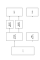
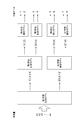
- FIG. 1 is a block diagram showing a functional configuration of the information processing device 100, which is the model estimation device of the present embodiment.
- the information processing apparatus 100 includes a log information acquisition unit 101, a state estimation unit 102 (estimation processing unit), an explanation estimation unit 103 (explanatory estimation unit), and a model storage unit 104 (model storage unit, description).
- a model storage unit) and a log information storage unit 105 are included.
- the information processing device 100 may be a server located on the network or a communication terminal that can be directly operated by the user.
- the log information acquisition unit 101 is a part that acquires log information from the log information DB 105a and converts it into a feature amount.
- the state estimation unit 102 is a part that estimates the user's state by using the state estimation model stored in the model storage unit 104 and the log information stored in the log information storage unit 105.
- the state estimation unit 102 can estimate the state such as the user's attention or stress by inputting this log information as a feature amount or after converting it into a predetermined feature amount format into the state estimation model. ..
- the device is not limited to estimating the user's state, and may be a device that estimates the input using a learning model.
- the model storage unit 104 is a part that stores a learning model constructed by machine learning.
- the model storage unit 104 stores the state estimation model 104a and the explanatory estimation model 104b as learning models.
- the state estimation model 104a is, for example, a learning model in which a learning process is performed using a feature amount based on log information as an explanatory variable and a user state as an objective variable.
- This state estimation model 104a is constructed by a plurality of estimation models.
- the state estimation model 104a is constructed by the first state estimation model 104a1, the second state estimation model 104a2, and the third state estimation model 104a3.
- the state estimation unit 102 estimates the user's first state or second state using the first state estimation model 104a1. Then, according to the estimation result, the state estimation unit 102 estimates a more detailed state of the user by using the estimation model of either the second state estimation model 104a2 or the third state estimation model 104a3. For example, when the user is in the first state, the state estimation unit 102 estimates the detailed state of the user by using the second state estimation model 104a2.
- the explanatory estimation model 104b is a learning model showing the basis of the user's state estimated based on the feature amount based on the log information which is the input data. Description The estimation model 104b is constructed by SHAP (SHapley Additive exPlanations) or LIMIT (Local Interpretable Model-agnostic Explanations). SHAP or LIMIT is a model for calculating how each feature has an effect on prediction. SHAP is a method of giving interpretability by approximating the prediction result of a complicated estimation model using a simpler model.
- the explanatory estimation model 104b is a learning model that is also constructed when the state estimation model 104a is constructed.
- the first state estimation model 104a1 and the explanatory estimation model 104b are models constructed based on the same input data (features) and the same teacher signal, and they are in a paired relationship.
- the log information storage unit 105 stores the log information DB 105a.
- the log information DB 105 stores log information such as an operation history of a communication terminal such as a smartphone held by a user, for example. This log information is information in which the time is associated with the operation history and the like.
- the presenting unit 106 presents the user's state (for example, user's attention, stress, etc.) estimated by the state estimating unit 102 to the user or others together with the basis of the user's state estimated by the explanatory estimation unit 103. It is a part.
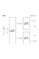
- FIG. 2 is a schematic diagram showing an estimation process using the first state estimation model 104a1, the second state estimation model 104a2, the third state estimation model 104a3, and the explanatory estimation model 104b.
- the first state estimation model 104a1 and the explanatory estimation model 104b estimate the user's state and its estimation basis, respectively, by inputting input data.
- the first state estimation model 104a1 estimates whether the user is in the first state or the second state with respect to the feature amount based on the log information. For example, if the first state estimation model 104a1 is a model used for estimating the attention of the user, the first state is the state in which the user is attentive, and the second state is the state in which the user is not attentive. It is a model for estimation.
- the second state estimation model 104a2 is an estimation model that is applied when the user's state is estimated to be the first state.
- the second state estimation model 104a2 re-inputs a feature amount based on the log information input to the first state estimation model 104a1, and outputs an estimation result based on the feature amount.
- the third state estimation model 104a3 is an estimation model that is applied when the user's state is estimated to be the second state.
- the third state estimation model 104a3 inputs a feature amount based on the log information input to the first state estimation model 104a1 again, and outputs an estimation result based on the feature amount.
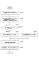
- FIG. 3 is a flowchart showing the process.
- the log information acquisition unit 101 acquires log information from the log information DB 105a and converts it into a feature amount (S101). Then, the state estimation unit 102 inputs the feature amount acquired by the log information acquisition unit 101 into the first state estimation model 104a1 and acquires the estimation result (S102). Further, the explanatory estimation unit 103 inputs the feature amount acquired by the log information acquisition unit 101 into the explanatory estimation model 104b, and estimates the feature amount (log information) that has influenced the estimation result of the first state estimation model 104a1. (S102). Here, the explanatory estimation unit 103 calculates the SHAP value by inputting the same feature amount into the explanatory estimation model 104b, and estimates the feature amount that has influenced the estimation result based on the value. This process will be described later.
- the state estimation unit 102 estimates that the user is in the first state as the estimation result (s103: YES)
- the feature amount acquired by the log information acquisition unit 101 is input again into the second state estimation model 104a2.
- the state estimation unit 102 performs an estimation process using the second state estimation model 104a2 (S104).
- the state estimation unit 102 estimates that the user is in the first state as the estimation result (S103: NO)
- the feature amount acquired by the log information acquisition unit 101 is input to the third state estimation model 104a3. ..
- the state estimation unit 102 performs an estimation process using the third state estimation model 104a3 (S105).
- the state estimation unit 102 acquires the estimation basis and the estimation result (S106), and the presentation unit 106 outputs the estimation basis and the estimation result (S107).
- FIG. 4 shows a detailed process in the basis estimation process shown in FIG. Specifically, the detailed processing of the estimation basis processing of the processing S102 is shown.
- the state estimation unit 102 estimates whether it is the first state or the second state by inputting the feature amount into the state estimation model 104a1 (S103, corresponding to S103 in FIG. 3).
- the explanatory estimation unit 103 acquires the top N features among the features that contributed to the first state based on the calculated SHAPvalue (S201). ..
- the explanatory estimation unit 103 acquires the top N features among the features that contributed to the second state (S202).
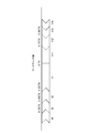
- FIG. 5 is a diagram schematically showing SHAPvalue, which visualizes the contribution of each feature amount.
- the baseline shows the expected value of the entire dataset.
- the feature amount pointing to the right with respect to the baseline (graphic arrow: the feature amount on the left side of the baseline) represents a positive contribution to the estimated state, and the feature amount pointing to the left (graphic arrow).
- Features on the right side of the baseline represents a negative contribution to the estimated state.
- the length of the graphic arrow indicates its contribution to the expected value.
- the feature amount t1 has a length of about 0.11, indicating that it has increased (contributed) by about 0.11 to the state estimation.
- the features affect the estimated state in the order of the lengths of the arrows, and the top N features are acquired.
- the number of estimation grounds presented to the user is limited according to the estimation result.
- the explanatory estimation unit 103 compares each acquired feature amount with the average value of the user over a certain period of time (S203). When the acquired feature amount ⁇ the past average value (S204), it is determined that the behavior that is the basis of the feature amount has increased more than in the past (S205). For example, in the operation of a smartphone, when the feature amount of the predetermined operation is larger than the past average, it is determined that the predetermined operation has increased. That is, it is judged that the behavior has a great influence on the state estimation.
- the explanatory estimation unit 103 temporarily stores these estimation grounds (S207). The saved estimation basis is output together with the estimation result of the state estimation as shown in FIG.
- the number of estimation grounds presented to the user is limited according to the estimation result.
- the stress is estimated to be high in the first state estimation model, only the features that contributed to the estimation of the stress are presented to the user.
- the stress is estimated to be low: 0 in the first state estimation model, only the features that contributed to the estimation of the stress are presented to the user. At that time, it is possible to inform the user whether the behavior that is the basis of the judgment of the level of stress is more or less than the past behavior.
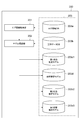
- FIG. 6 is a block diagram showing a functional configuration of the model building apparatus 200.
- the model construction device 200 includes a log information acquisition unit 201, a model construction unit 202, and a storage unit 203.
- the log information acquisition unit 201 is a part that acquires log information from the log information DB 203a and converts it into a feature amount for model construction.
- the storage unit 203 is a part that stores each database and the estimation model, and includes log information DB 203a, correct answer data DB 203b, first state estimation model 203c1, second state estimation model 203c2, third state estimation model 203c3, and explanatory estimation model 203d.
- the first state estimation model 203c1, the second state estimation model 203c2, the third state estimation model 203c3, and the explanation estimation model 203d are the state estimation model and the explanation estimation model constructed by the model construction unit 202, and the first state estimation model in FIG. It corresponds to the state estimation model 104a1, the second state estimation model 104a2, the third state estimation model 104a3, and the explanatory estimation model 104b.
- FIG. 7 is a flowchart showing a process for constructing each state estimation model.
- the log information acquisition unit 201 acquires log information from the log information DB 203a, converts it into a feature amount, and inputs it to the model construction unit 202. Further, the model construction unit 202 acquires the correct answer data from the correct answer data DB 203b (S301).
- the correct answer data stored in the correct answer data DB 203b is data prepared in advance. For example, when the correct answer data is in a state showing the user's attention, the correct answer data is prepared by the user taking a test or the like for measuring the attention in advance. At that time, it is necessary that the correct answer data and the feature amount (log information) correspond in time.
- the model building unit 202 builds the first state estimation model 203c1 for estimating whether it is the first state or the second state by using the feature amount and the correct answer data.
- the model construction unit 202 performs learning processing using the feature amount as an explanatory variable and the binarized information of the correct answer data as the objective variable, and constructs the first state estimation model (S302).
- the model building unit 202 also builds the explanatory estimation model 203d.
- the construction process uses the construction method of the estimation model, which is also known as the above-mentioned SHAP or LIMIT.
- the binarized information of the correct answer data means that the correct answer data is redefined as 1 or 2 according to a predetermined rule. For example, if the correct answer data is represented by five values (1 to 5), it means that 1 and 2 of the correct answer data are set to 1 and 3 to 5 are set to 2.
- the binarization process is not limited to this.
- each function of the model building apparatus 200 may be provided in the information processing apparatus 100.
- the model construction unit 202 acquires the correct answer data indicating the first state and the second state and the corresponding feature amount for each state (S303). That is, the feature amount estimated to be the first state and the feature amount estimated to be the second state are acquired, respectively.
- the model building unit 202 builds a second state estimation model 203c2 that estimates the first state in detail using the correct answer data indicating the first state and the corresponding feature amount (S304). For example, the correct answer data indicating the first state is 1 and 2, and the second state estimation model 203c2 is constructed by performing the learning process using the feature quantities in which the correct answer data are 1 and 2.
- the model building unit 202 builds a third state estimation model 203c3 that estimates the second state in detail using the correct answer data indicating the second state and the corresponding feature amount (S305). For example, the correct answer data indicating the second state is 3 to 5, and the third state estimation model 203c3 is constructed by performing the learning process using the feature amount in which the correct answer data is 3 to 5.
- the model construction unit 202 connects the first state estimation model 203c1 to the third state estimation model 203c3 (S306). That is, when it is estimated that the first state is in the first state estimation model 203c1, it is connected to the second state estimation model 203c2 so as to continue the estimation. The same applies to the third state estimation model 203c3.
- the state estimation unit 102 shown in FIG. 1 can apply the state estimation model 104a (203a) according to the user's state by using the connected estimation model.
- FIG. 8 is a schematic diagram showing the generation process of each state estimation model 203a.
- 1 to 5 are set as correct answer data
- x1 to xn are set as input feature quantities.
- the learning process is performed by replacing the correct answer data corresponding to the feature quantities x1 to xn with 1 or 2. For example, if the correct answer data corresponding to the feature amounts x11 to x1n is 1, the correct answer data corresponding to the feature amounts x21 to x2n is 2, and the correct answer data corresponding to the feature amounts x31 to x3n is 3, the feature amounts x11 to x1n. And the correct answer data of the feature amounts x21 to x2n is set to 1, and the correct answer data corresponding to the feature amounts x31 to x3n is set to 2.
- the correct answer data 1 and 2 are converted into the correct answer data of 1, and the correct answer data 3 to 5 are converted into the correct answer data of 2.
- the first state estimation model 203c1 can be constructed by performing the learning process using these converted correct answer data as the objective variables.
- the first state estimation model 203c1 can output 1 or 2 as correct answer data for the feature quantities x1 to xn.
- the second state estimation model 203c2 When the second state estimation model 203c2 is generated, the feature quantities xa1 to xan with the correct answer data as 1 or 2 are extracted from the feature quantities xm1 to xmn of the feature quantities x11 to x1n.
- the second state estimation model 203c2 can be constructed by performing the learning process using the extracted feature quantities xa1 to xan as explanatory variables and the correct answer data 1 or 2 corresponding to those feature quantities as objective variables. The same applies to the construction process of the third state estimation model 203c3.
- the estimation model can be constructed step by step.
- the application and construction of two estimation models connected in series have been described, but the present invention is not limited to this.
- three estimation models may be connected in series to construct an estimation model, which may be applied to an estimation process based on a feature amount.
- the first state estimation model is constructed by replacing 1 to 4 of the correct answer data with 1 and replacing 5 to 8 of the correct answer data with 2.
- the information processing apparatus 100 has a log information storage unit 105 that stores log information DB 105a of log information that is input data, and a first unit for estimating a user state corresponding to an output state based on a feature amount of log information.
- 1 state estimation model 104a1 a second state estimation model 104a2 for estimating a more detailed state when the user's state is a predetermined state (for example, a state with attention), and a first state estimation model 104a1.
- the memory 1002 is a computer-readable recording medium, and is composed of at least one such as a ROM (Read Only Memory), an EPROM (Erasable Programmable ROM), an EPROM (Electrically Erasable Programmable ROM), and a RAM (Random Access Memory). May be done.
- the memory 1002 may be referred to as a register, a cache, a main memory (main storage device), or the like.
- the memory 1002 can store a program (program code), a software module, or the like that can be executed to implement the state estimation method and the estimation model construction method according to the embodiment of the present disclosure.
- Software is an instruction, instruction set, code, code segment, program code, program, subprogram, software module, whether called software, firmware, middleware, microcode, hardware description language, or another name.
- Applications, software applications, software packages, routines, subroutines, objects, executable files, execution threads, procedures, features, etc. should be broadly interpreted to mean.
- judgment and “decision” mean that “resolving”, “selecting”, “choosing”, “establishing”, “comparing”, etc. are regarded as “judgment” and “decision”. Can include. That is, “judgment” and “decision” may include that some action is regarded as “judgment” and “decision”. Further, “judgment (decision)” may be read as “assuming”, “expecting”, “considering” and the like.
Landscapes
- Engineering & Computer Science (AREA)
- Health & Medical Sciences (AREA)
- Medical Informatics (AREA)
- Public Health (AREA)
- Biomedical Technology (AREA)
- Data Mining & Analysis (AREA)
- Theoretical Computer Science (AREA)
- Pathology (AREA)
- Physics & Mathematics (AREA)
- General Health & Medical Sciences (AREA)
- Software Systems (AREA)
- Life Sciences & Earth Sciences (AREA)
- Primary Health Care (AREA)
- Databases & Information Systems (AREA)
- General Physics & Mathematics (AREA)
- Epidemiology (AREA)
- Business, Economics & Management (AREA)
- Psychiatry (AREA)
- Mathematical Physics (AREA)
- General Engineering & Computer Science (AREA)
- Computing Systems (AREA)
- Computer Vision & Pattern Recognition (AREA)
- Evolutionary Computation (AREA)
- Artificial Intelligence (AREA)
- Strategic Management (AREA)
- Human Resources & Organizations (AREA)
- Economics (AREA)
- Educational Technology (AREA)
- Molecular Biology (AREA)
- Veterinary Medicine (AREA)
- Animal Behavior & Ethology (AREA)
- Surgery (AREA)
- Heart & Thoracic Surgery (AREA)
- Biophysics (AREA)
- Child & Adolescent Psychology (AREA)
- Developmental Disabilities (AREA)
- Social Psychology (AREA)
- Hospice & Palliative Care (AREA)
- Psychology (AREA)
- Game Theory and Decision Science (AREA)
Abstract
状態推定モデルを用いた推定結果の根拠を適格に提示することのできる情報処理装置を提供することを目的とする。 情報処理装置100は、ログ情報に基づいて、ユーザの状態を推定するための第1状態推定モデル104a1と、ユーザの状態が所定の状態である場合において、さらに詳細な状態を推定するための第2状態推定モデル104a2と、第1状態推定モデル104a1の推定結果に対する推定根拠を、ログ情報を用いて説明するための説明推定モデル104bとを記憶するモデル記憶部104と、第1状態推定モデル104a1および第2状態推定モデル104a2を用いて、ユーザの状態を推定する状態推定部102と、説明推定モデル104bに基づいて第1状態推定モデル104a1の推定結果の推定根拠を推定する説明推定部103と、を備える。
Description
本発明は、学習モデルを用いてユーザの状態を判定する情報処理装置に関する。
スマートフォンなどの操作ログに基づいてユーザのストレス状態を推定する技術が知られている。
Cognitive Rhythms: Unobtrusiveand Continuous Sensing of Alertness Using a Mobile PhoneSaeed Abdullah, Elizabeth Murnane, MarkMatthews, Matthew Kay, Julie Kientz, Geri Gay, Tanzeem Choudhury, Proceedingsof the 2016 ACM International Joint Conference on Pervasive and UbiquitousComputing. ACM, 2016.[平成30年2月6日検索]
推定結果と合わせて推定根拠を示すことがユーザに望まれているが、上記特許文献1においては、何を根拠にユーザのストレス状態が推定されたのか不明である。
そこで、本発明は、上述の課題を解決するために、推定モデルを用いた推定結果の根拠を適格に提示することのできる情報処理装置を提供することを目的とする。
本発明の情報処理装置は、入力データを記憶するログ情報記憶部と、前記入力データに基づいて、出力状態を推定するための第1推定モデル、および前記出力状態が所定の状態である場合において、さらに詳細な状態を推定するための第2状態推定モデル、を記憶するモデル記憶部と、前記第1推定モデルおよび第2状態推定モデルを用いて、入力データに対する出力状態を推定する推定処理部と、前記第1推定モデルの推定結果に対する推定根拠を、前記入力データを用いて説明するための説明モデルを記憶する説明モデル記憶部と、前記説明モデルに基づいて第1推定モデルの推定結果の推定根拠を推定する説明推定部と、を備える。
この発明によれば、推定モデルを用いた出力状態を提示するとともに、その推定結果の根拠を適格に提示することができる。
本発明によれば、推定モデルを用いた出力状態を提示するとともに、その推定結果の根拠を適格に提示することができる。
添付図面を参照しながら本発明の実施形態を説明する。可能な場合には、同一の部分には同一の符号を付して、重複する説明を省略する。
図1は、本実施形態のモデル推定装置である情報処理装置100の機能構成を示すブロック図である。図1に示されるとおり、この情報処理装置100は、ログ情報取得部101、状態推定部102(推定処理部)、説明推定部103(説明推定部)、モデル記憶部104(モデル記憶部、説明モデル記憶部)、およびログ情報記憶部105を含んで構成されている。以下、図に基づいて説明する。この情報処理装置100は、ネットワーク上には位置されているサーバでもよいし、ユーザが直接操作可能な通信端末であってもよい。
ログ情報取得部101は、ログ情報DB105aからログ情報を取得し、これを特徴量に変換する部分である。
状態推定部102は、モデル記憶部104に記憶されている状態推定モデルと、ログ情報記憶部105に記憶されているログ情報とを用いて、ユーザの状態推定を行う部分である。
例えば、ログ情報として、ユーザが保持するスマートフォンなどの通信端末の操作履歴、移動履歴、およびアクセス履歴などの少なくとも一つが考えられる。状態推定部102は、このログ情報を、特徴量として、または所定の特徴量形式に変換して、状態推定モデルに入力することで、ユーザの注意力またはストレスなどの状態を推定することができる。
また、ユーザの状態を推定することに限定するものではなく、入力に対して学習モデルを用いて推定する装置であればよい。
説明推定部103は、ログ情報記憶部に記憶されているログ情報と、モデル記憶部104の説明推定モデル104bとを用いて、状態推定部102が推定したユーザの状態の根拠を推定する部分である。説明推定部103は、ログ情報取得部101が入力したログ情報を入力することで、推定したユーザの状態の根拠を推定することができる。
モデル記憶部104は、機械学習により構築された学習モデルを記憶する部分である。モデル記憶部104は、学習モデルとして、状態推定モデル104aと説明推定モデル104bとを記憶する。
状態推定モデル104aは、例えば、ログ情報に基づいた特徴量を説明変数とし、ユーザの状態を目的変数として、学習処理がなされた学習モデルである。この状態推定モデル104aは、複数の推定モデルで構築されている。例えば、状態推定モデル104aは、第1状態推定モデル104a1、第2状態推定モデル104a2、および第3状態推定モデル104a3で構築されている。
状態推定部102は、第1状態推定モデル104a1を用いて、ユーザの第1状態または第2状態を推定する。そして、その推定結果に応じて、状態推定部102は、第2状態推定モデル104a2または第3状態推定モデル104a3のいずれかかの推定モデルを利用して、ユーザのさらに詳細な状態を推定する。例えば、状態推定部102は、ユーザが第1状態である場合には、第2状態推定モデル104a2を用いて、ユーザの詳細な状態を推定する。
説明推定モデル104bは、入力データであるログ情報に基づいた特徴量に基づいて推定されたユーザの状態の根拠を示す学習モデルである。説明推定モデル104bは、SHAP(SHapley Additive exPlanations)またはLIME(LocalInterpretable Model-agnostic Explanations)により構築されている。SHAPまたはLIMEは、それぞれの特徴量が予測に対してどのような影響を与えたか算出するためのモデルである。また、SHAPは,複雑な推定モデルの予測結果をよりシンプルなモデルを使って近似することにより解釈性を与える手法である。この説明推定モデル104bは、状態推定モデル104aの構築時において合わせて構築される学習モデルである。この第1状態推定モデル104a1と説明推定モデル104bとは、同じ入力データ(特徴量)および同じ教師信号に基づいて構築されたモデルであり、両者は対の関係である。
ログ情報記憶部105は、ログ情報DB105aを記憶している。このログ情報DB105は、例えばユーザが保持するスマートフォンなどの通信端末の操作履歴等のログ情報を記憶する。このログ情報は、時刻とその操作履歴等とを対応付けた情報である。
提示部106は、状態推定部102により推定されたユーザの状態(例えばユーザの注意力、ストレスなど)を、説明推定部103により推定されたそのユーザの状態の根拠とともに、ユーザまたはその他に提示する部分である。
図2は、第1状態推定モデル104a1、第2状態推定モデル104a2、第3状態推定モデル104a3、および説明推定モデル104bを用いた推定処理を示す模式図である。図2に示されるように、第1状態推定モデル104a1と説明推定モデル104bとは、入力データを入力することにより、それぞれユーザの状態およびその推定根拠を推定する。
図2において、第1状態推定モデル104a1は、ログ情報に基づいた特徴量に対して、ユーザが第1状態または第2状態のいずれかであるかを推定する。例えば、第1状態推定モデル104a1は、ユーザの注意力を推定するために用いられるモデルであれば、第1状態がユーザに注意力がある状態、第2状態がユーザに注意力がない状態を推定するためのモデルである。
第2状態推定モデル104a2は、ユーザの状態が第1状態と推定された場合に、適用される推定モデルである。この第2状態推定モデル104a2は、第1状態推定モデル104a1に入力されたログ情報に基づいた特徴量を、改めて入力し、その特徴量に基づいて推定結果を出力する。
第3状態推定モデル104a3は、ユーザの状態が第2状態と推定された場合に、適用される推定モデルである。この第3状態推定モデル104a3は、第1状態推定モデル104a1に入力されたログ情報に基づいた特徴量を、改めて入力し、その特徴量に基づいて推定結果を出力する。
一方、説明推定モデル104bは、上記と同じ特徴量を入力し、第1状態推定モデル104a1において推定された結果に影響力のある特徴量を、推定根拠の説明として出力する。例えば、説明推定モデル104bが、SHAPvalueで構築されていれば、その値を出力する。SHAP valueについては後述する。
つぎに、本実施形態の情報処理装置100の状態推定処理および根拠推定処理について説明する。図3は、その処理を示すフローチャートである。
ログ情報取得部101は、ログ情報をログ情報DB105aから取得し、特徴量に変換する(S101)。そして、状態推定部102は、ログ情報取得部101が取得した特徴量を第1状態推定モデル104a1に入力し、推定結果を取得する(S102)。また、説明推定部103は、ログ情報取得部101が取得した特徴量を説明推定モデル104bに入力し、第1状態推定モデル104a1の推定結果に影響を及ぼした特徴量(ログ情報)を推定する(S102)。ここでは、説明推定部103は、説明推定モデル104bに、同じ特徴量を入力することにより、SHAP valueを算出し、その値に基づいて、推定結果に影響を及ぼした特徴量を推定する。この処理については後述する。
状態推定部102が、推定結果としてユーザが第1状態であることを推定すると(s103:YES)、第2状態推定モデル104a2に、ログ情報取得部101が取得した特徴量を再度入力する。そして、状態推定部102は、第2状態推定モデル104a2を用いた推定処理を行う(S104)。
状態推定部102が、推定結果としてユーザが第1状態であることを推定すると(S103:NO)、第3状態推定モデル104a3に、ログ情報取得部101が取得して得た特徴量を入力する。そして、状態推定部102は、第3状態推定モデル104a3を用いた推定処理を行う(S105)。
そして、状態推定部102は、推定根拠と推定結果とを取得し(S106)、提示部106は、推定根拠と推定結果とを出力する(S107)。
このようにして、説明推定モデル104bを用いた推定結果に対する適格な根拠を示すとともに、状態推定モデル104a1~104a3を用いて、詳細な状態推定を行うことができる。
つぎに、説明推定モデル104bを用いた推定根拠の推定処理について説明する。図4は、図3に示した根拠推定処理に詳細処理を示す。具体的には、処理S102の推定根拠処理の詳細処理を示す。
状態推定部102は、状態推定モデル104a1に特徴量を入力することにより、第1状態であるか、第2状態であるかを推定する(S103、図3におけるS103に相当)。その推定結果が、第1状態である場合には、説明推定部103は、算出したSHAPvalueに基づいて、第1状態に寄与した特徴量のうち、上位N件の特徴量を取得する(S201)。また、推定結果が第2状態である場合には、説明推定部103は、第2状態に寄与した特徴量のうち、上位N件の特徴量を取得する(S202)。
ここで図を用いてSHAP valueについて説明する。SHAP valueは,各推定結果に対して,それぞれの特徴量がその推定結果にどのような影響を与えたのかを算出する手法である。図5は、SHAPvalueを模式的に示した図であり、各特徴量の寄与度を可視化したものである。この図において、ベースラインはデータセット全体の期待値を示す。ベースラインに対して右方向に向いている特徴量(図形矢印:ベースラインの左側の特徴量)は、推定した状態に対して正の寄与を表し、左方向に向いている特徴量(図形矢印:ベースラインの右側の特徴量)は、推定した状態に対して負の寄与を表している。図形矢印の長さが、その期待値への寄与度を示す。
例えば、特徴量t1はおおむね0.11の長さであり、状態推定に対して0.11ほど増加(寄与)したことを示している。
ここでは、この矢印の長さの順に、推定した状態に影響を及ぼした特徴量であると考えることができ、上位N件の特徴量を取得する。ここでは、推定結果に応じてユーザに提示する推定根拠の件数を制限している。
説明推定部103は、取得した各特徴量と、そのユーザの過去一定期間の平均値と比較する(S203)。取得した特徴量≧過去の平均値である場合には(S204)、その特徴量の元となる行動は、過去よりも多くなったと判断する(S205)。例えば、スマートフォンの操作において、所定の操作の特徴量が過去平均より多い場合には、その所定の操作が多くなったと判断する。すなわち、その行動が状態推定に対して大きな影響を及ぼしていると判断する。
また、取得した特徴量≧過去の平均値ではない場合には(S204)、その特徴量の元となる行動は、過去よりも少なくなったと判断する(S206)。そして、説明推定部103は、これら推定根拠を一時保存する(S207)。保存された推定根拠は、図3において示された通り、状態推定の推定結果とともに出力される。
上述したとおり、推定結果に応じてユーザに提示する推定根拠の件数を制限している。第1状態推定モデルにおいてストレスが高:1と推定された場合には,ストレスを高いと推定することに寄与した特徴量のみをユーザに提示する。また、逆に第1状態推定モデルにおいてストレスが低:0と推定された場合には,ストレスを低いと推定することに寄与した特徴量のみをユーザに提示する。その際、そのストレスの高低の判断の根拠となった行動が過去の行動と比較して、多くなったか低くなったかをユーザに知らせることが可能となる。
つぎに、このような処理を実現する第1状態推定モデル104a1~第3状態推定モデル104a3の学習モデル構築処理について説明する。図6は、モデル構築装置200の機能構成を示すブロック図である。図6に示される通り、モデル構築装置200は、ログ情報取得部201、モデル構築部202、および記憶部203を含んで構成されている。
ログ情報取得部201は、ログ情報DB203aからログ情報を取得して、モデル構築のための特徴量に変換する部分である。
モデル構築部202は、ログ情報を説明変数とし、正解データを目的変数として、学習処理を行うことにより、状態推定モデルおよび説明推定モデルを構築する部分である。
記憶部203は、各データベースおよび推定モデルを記憶する部分であり、ログ情報DB203a、正解データDB203b、第1状態推定モデル203c1、第2状態推定モデル203c2、第3状態推定モデル203c3、説明推定モデル203dを記憶する。第1状態推定モデル203c1、第2状態推定モデル203c2、第3状態推定モデル203c3、説明推定モデル203dは、モデル構築部202により構築された状態推定モデルおよび説明推定モデルであり、図1における第1状態推定モデル104a1、第2状態推定モデル104a2、第3状態推定モデル104a3、および説明推定モデル104bに相当する。
図7は、各状態推定モデルを構築するための処理を示すフローチャートである。ログ情報取得部201は、ログ情報DB203aからログ情報を取得し、特徴量に変換し、モデル構築部202に入力する。また、モデル構築部202は、正解データDB203bから正解データを取得する(S301)。
なお、正解データDB203bに記憶されている正解データは、予め用意されたデータである。例えば、正解データがユーザの注意力を示す状態である場合には、ユーザが事前に注意力を測定するための試験等を受けることにより正解データが用意される。その際、正解データと特徴量(ログ情報)とが時間的な対応をとっておくことが必要である。
モデル構築部202は、特徴量と正解データとを用いて、第1状態か第2状態かを推定するための第1状態推定モデル203c1を構築する。モデル構築部202は、特徴量を説明変数とし、正解データを二値化した情報を目的変数として、学習処理を行い、第1状態推定モデルを構築する(S302)。なお、モデル構築部202は、説明推定モデル203dを合わせて構築する。その構築処理は、上述したSHAPまたはLIMEなど公知の説明も推定モデルの構築手法を用いる。
ここで正解データを二値化した情報とは、正解データを所定のルールで1または2で規定し直すことをいう。例えば、正解データが5値(1~5)で表されたとすると、正解データの1および2を1とし、3~5を2とすることをいう。なお、二値化処理は、これに限るものではない。
なお、モデル構築装置200の各機能は、情報処理装置100に備えられてもよい。
つぎに、モデル構築部202は、第1状態および第2状態を示す正解データと、それに対応する特徴量とをそれぞれの状態に対して取得する(S303)。すなわち、第1状態と推定された特徴量および第2状態と推定された特徴量をそれぞれ取得する。
モデル構築部202は、第1状態を示す正解データとそれに対応する特徴量とを用いて、第1状態を詳細に推定する第2状態推定モデル203c2を構築する(S304)。例えば、第1状態を示す正解データは1および2であり、正解データを1および2とする特徴量を用いて、学習処理を行うことで第2状態推定モデル203c2を構築する。
モデル構築部202は、第2状態を示す正解データとそれに対応する特徴量とを用いて、第2状態を詳細に推定する第3状態推定モデル203c3を構築する(S305)。例えば、第2状態を示す正解データは3~5であり、正解データを3~5とする特徴量を用いて、学習処理を行うことで第3状態推定モデル203c3を構築する。
そして、モデル構築部202は、第1状態推定モデル203c1~第3状態推定モデル203c3を連結する(S306)。すなわち、第1状態推定モデル203c1において第1状態であると推定されると、第2状態推定モデル203c2に推定を継続させるように連結する。第3状態推定モデル203c3についても同様である。図1に示した状態推定部102は、この連結された推定モデルを用いて、ユーザの状態に応じた状態推定モデル104a(203a)を適用することができる。
図8は、各状態推定モデル203aの生成過程を示す模式図である。この例示においては、正解データとして1から5が設定され、入力される特徴量としてx1~xnが設定されている。
第1状態推定モデル203c1を生成する際には、特徴量x1~xnに対応する正解データを1または2に置き換えて、学習処理が行われる。例えば、特徴量x11~x1nに対応する正解データ:1、特徴量x21~x2nに対応する正解データ:2、特徴量x31~x3nに対応する正解データ:3、とした場合、特徴量x11~x1nおよび特徴量x21~x2nの正解データを、1とし、特徴量x31~x3nに対応する正解データ:2とする。
すなわち正解データである1および2を、1とする正解データに変換され、正解データである3~5を、2とする正解データに変換される。そして、これら変換された正解データを目的変数として学習処理を行うことで、第1状態推定モデル203c1を構築することができる。この第1状態推定モデル203c1は、特徴量x1~xnに対して、正解データとして1または2を出力することができる。
第2状態推定モデル203c2を生成する際には、特徴量x11~x1nから特徴量xm1~xmnのそれぞれの特徴量のうち、正解データを1または2とした特徴量xa1~xanを抽出する。それら抽出された特徴量xa1~xanを説明変数とし、それら特徴量に対応する正解データ1または2を目的変数とした学習処理を行うことで、第2状態推定モデル203c2を構築することができる。第3状態推定モデル203c3の構築処理も同様である。
このようにして、段階的に推定モデルを構築することができる。なお、上述の説明では2つの推定モデルを直列に接続しての適用およびその構築について説明したが、これに限るものではない。例えば、図9に示すように3つの推定モデルを直列に連結して推定モデルを構築し、それを特徴量に基づいた推定処理に適用してもよい。この例によると、正解データの1~4を1、正解データの5~8を2に置き換えて第1状態推定モデルを構築している。
つぎに、本実施形態の情報処理装置100の作用効果について説明する。この情報処理装置100は、入力データであるログ情報のログ情報DB105aを記憶するログ情報記憶部105と、ログ情報の特徴量に基づいて、出力状態に相当するユーザの状態を推定するための第1状態推定モデル104a1と、ユーザの状態が所定の状態である場合(例えば注意力がある状態)において、さらに詳細な状態を推定するための第2状態推定モデル104a2と、第1状態推定モデル104a1の推定結果に対する推定根拠を、ログ情報に基づいた特徴量を用いて説明するための説明推定モデル104bとを記憶するモデル記憶部104と、第1状態推定モデル104a1および第2状態推定モデル104a2を用いて、ログ情報に対するユーザの状態を推定する状態推定部102と、説明推定モデル104bに基づいて第1状態推定モデル104a1の推定結果の推定根拠を推定する説明推定部103とを備える。
この情報処理装置100によれば、第1状態推定モデル104a1を用いてユーザの状態を推定するとともに、その推定根拠を推定することができる。また、第2状態推定モデル104a2を用いてさらに詳細なユーザの状態を推定することができる。したがって、ユーザの状態をより詳細に推定するとともに、ユーザの状態を推定したその根拠については、解釈容易にすることができる。そして、複数の推定モデルを利用することで、CPU等制御部の処理不可を軽減するとともに、その処理速度を向上させることができる。
より詳細には、状態推定モデル104aを直列的に連結することで、前段の第1状態推定モデル104a1を用いて状態推定し、その後段の第2状態推定モデル104a2を用いてさらに詳細な状態推定を行うことができる。一方で、説明推定モデル104bは、前段で推定された状態に対する推定根拠を明確にする。
説明推定モデル104bは、状態推定モデル104a1を構築する際に、合わせて構築されるモデルであり、両者は対応関係にある。例えば、第1状態推定モデル104a1を二値推定モデルとすると、説明推定モデル104bも二値推定モデルとなる。また、第1状態推定モデル104a1を三値推定モデルとすると、説明推定モデル104bも三値推定モデルとなる。したがって、状態推定とその推定根拠の推定粒度は同じとなる。
状態推定を行うにあたって、細かな状態の根拠を把握することは困難な場合が多く、またそこに重要性を見いださない場合が多い。例えば、ユーザの注意力を5値評価する場合において、注意力が5である場合と、注意力が4である場合とを推定することがある。この場合、注意力が4であること、また5であることの推定根拠を正確に解釈することは困難である。
ユーザの注意力が4と5で異なる場合には、そのログ情報も似た多様なものとなる。したがって、説明推定モデル104bを適用した場合には、その説明が似たようなものとなり、ユーザにとって、何故そのような推定根拠となったのか、違いが分かりづらい。一方で、ユーザの注意力が1である場合と、注意力が5である場合との推定根拠を推定することは比較的容易であり、またその推定根拠には重要性がある場合が多い。すなわち、注意力が1と5では、そのログ情報が異なる場合が多く、その説明の違いが大きくなる。
そのため、上述したとおり本実施形態の情報処理装置100においては、推定モデルを直列に連結して、2段構成とすることで、1段目の第1状態推定モデル104a1の後にさらに第2状態推定モデル104a2を連結することで、状態推定の粒度を細かくすることができる一方で、説明推定モデル104bは、第1状態推定モデル104a1の推定粒度に合わせた推定根拠の推定を可能にする。したがって、推定根拠を把握しやすくするとともに、またその推定根拠を重要なものとして扱うことを可能にする。
一方で、第1状態推定モデル104a1のみを用いた場合には、その状態推定の粒度は荒いため、さらに詳細な状態推定を行うことが必要とされる。
上記説明において、入力データをログ情報とし、それに基づいた推定結果としてユーザの状態としたが、これに限るものではない。何らかの入力データがあり、それに基づいた推定を行う処理に本実施形態は適用できる。また、必ずしもログ情報を特徴量に変換する必要も無い。
また、情報処理装置100において、モデル記憶部104は、さらに、第3状態推定モデル104a3を記憶する。そして、第1状態推定モデル104a1は、ログ情報に対するユーザの状態が第1状態であるか、第2状態であることを推定するための学習モデルあり、第2状態推定モデル104a2は、ユーザの状態が第1状態である場合において、さらに詳細な状態を判定するための学習モデルである。また、第3状態推定モデル104a3は、ユーザの状態が第2状態である場合において、さらに詳細な状態を判定するための学習モデルである。
この情報処理装置100によれば、第1状態推定モデル104a1を、二値推定処理を行うモデルとすることで、それに対応する説明推定モデル104bも、二値推定処理に基づいた説明推定を行うことができる。したがって、状態推定に対する推定根拠を把握しやすい形で提供することができる。
また、この情報処理装置100において、説明推定部103は、推定結果の推定根拠として、ユーザの状態に影響を及ぼした一または複数の特徴量を示す。これにより、その推定根拠を把握することが容易となる。
また、この情報処理装置100において説明推定部103は、説明推定モデル104bから推定根拠となる特徴量を取得し、当該ログ情報における過去からの変化に基づいて、推定結果とログ情報とに対する分析を行う。
この情報処理装置100によれば、ログ情報が示すユーザの行動が過去より多くなった、または少なくなったなど具体的な分汗黄結果を提供できる。
また、モデル構築装置200は、第1状態推定モデル203c1を、特徴量と、当該ログ情報に対応して用意された正解データとに基づいて構築し、第2状態推定モデル203c2を、第1状態推定モデル104a1の構築に用いられたログ情報と当該ログ情報に対応する正解データのうち、第2状態推定モデル203c2を適用することを示した所定の状態に対応する正解データと、当該正解データに対応したログ情報とに基づいて構築する。
そして、情報処理装置100は、このように構築された第1状態推定モデル203c1等を、第1状態推定モデル104a1等として用いる。
これにより、その状態に応じた適切な状態推定モデルを構築することができる。
なお、ログ情報から特徴量に変換しない場合もあり、その場合において、上記において特徴量との記載をログ情報と読み替えてもよい。
上記実施形態の説明に用いたブロック図は、機能単位のブロックを示している。これらの機能ブロック(構成部)は、ハードウェア及びソフトウェアの少なくとも一方の任意の組み合わせによって実現される。また、各機能ブロックの実現方法は特に限定されない。すなわち、各機能ブロックは、物理的又は論理的に結合した1つの装置を用いて実現されてもよいし、物理的又は論理的に分離した2つ以上の装置を直接的又は間接的に(例えば、有線、無線などを用いて)接続し、これら複数の装置を用いて実現されてもよい。機能ブロックは、上記1つの装置又は上記複数の装置にソフトウェアを組み合わせて実現されてもよい。
機能には、判断、決定、判定、計算、算出、処理、導出、調査、探索、確認、受信、送信、出力、アクセス、解決、選択、選定、確立、比較、想定、期待、見做し、報知(broadcasting)、通知(notifying)、通信(communicating)、転送(forwarding)、構成(configuring)、再構成(reconfiguring)、割り当て(allocating、mapping)、割り振り(assigning)などがあるが、これらに限られない。たとえば、送信を機能させる機能ブロック(構成部)は、送信部(transmitting unit)や送信機(transmitter)と呼称される。いずれも、上述したとおり、実現方法は特に限定されない。
例えば、本開示の一実施の形態における情報処理装置100およびモデル構築装置200などは、本開示の推定モデル実行方法および推定モデル構築方法の処理を行うコンピュータとして機能してもよい。図10は、本開示の一実施の形態に係る情報処理装置100およびモデル構築装置200のハードウェア構成の一例を示す図である。上述の情報処理装置100およびモデル構築装置200は、物理的には、プロセッサ1001、メモリ1002、ストレージ1003、通信装置1004、入力装置1005、出力装置1006、バス1007などを含むコンピュータ装置として構成されてもよい。
なお、以下の説明では、「装置」という文言は、回路、デバイス、ユニットなどに読み替えることができる。情報処理装置100およびモデル構築装置200のハードウェア構成は、図に示した各装置を1つ又は複数含むように構成されてもよいし、一部の装置を含まずに構成されてもよい。
情報処理装置100およびモデル構築装置200における各機能は、プロセッサ1001、メモリ1002などのハードウェア上に所定のソフトウェア(プログラム)を読み込ませることによって、プロセッサ1001が演算を行い、通信装置1004による通信を制御したり、メモリ1002及びストレージ1003におけるデータの読み出し及び書き込みの少なくとも一方を制御したりすることによって実現される。
プロセッサ1001は、例えば、オペレーティングシステムを動作させてコンピュータ全体を制御する。プロセッサ1001は、周辺装置とのインターフェース、制御装置、演算装置、レジスタなどを含む中央処理装置(CPU:Central Processing Unit)によって構成されてもよい。例えば、上述の状態推定部102、説明推定部103などは、プロセッサ1001によって実現されてもよい。
また、プロセッサ1001は、プログラム(プログラムコード)、ソフトウェアモジュール、データなどを、ストレージ1003及び通信装置1004の少なくとも一方からメモリ1002に読み出し、これらに従って各種の処理を実行する。プログラムとしては、上述の実施の形態において説明した動作の少なくとも一部をコンピュータに実行させるプログラムが用いられる。例えば、状態推定部102などは、メモリ1002に格納され、プロセッサ1001において動作する制御プログラムによって実現されてもよく、他の機能ブロックについても同様に実現されてもよい。上述の各種処理は、1つのプロセッサ1001によって実行される旨を説明してきたが、2以上のプロセッサ1001により同時又は逐次に実行されてもよい。プロセッサ1001は、1以上のチップによって実装されてもよい。なお、プログラムは、電気通信回線を介してネットワークから送信されても良い。
メモリ1002は、コンピュータ読み取り可能な記録媒体であり、例えば、ROM(Read Only Memory)、EPROM(Erasable Programmable ROM)、EEPROM(Electrically Erasable Programmable ROM)、RAM(Random Access Memory)などの少なくとも1つによって構成されてもよい。メモリ1002は、レジスタ、キャッシュ、メインメモリ(主記憶装置)などと呼ばれてもよい。メモリ1002は、本開示の一実施の形態に係る状態推定方法および推定モデル構築方法を実施するために実行可能なプログラム(プログラムコード)、ソフトウェアモジュールなどを保存することができる。
ストレージ1003は、コンピュータ読み取り可能な記録媒体であり、例えば、CD-ROM(Compact Disc ROM)などの光ディスク、ハードディスクドライブ、フレキシブルディスク、光磁気ディスク(例えば、コンパクトディスク、デジタル多用途ディスク、Blu-ray(登録商標)ディスク)、スマートカード、フラッシュメモリ(例えば、カード、スティック、キードライブ)、フロッピー(登録商標)ディスク、磁気ストリップなどの少なくとも1つによって構成されてもよい。ストレージ1003は、補助記憶装置と呼ばれてもよい。上述の記憶媒体は、例えば、メモリ1002及びストレージ1003の少なくとも一方を含むデータベース、サーバその他の適切な媒体であってもよい。
通信装置1004は、有線ネットワーク及び無線ネットワークの少なくとも一方を介してコンピュータ間の通信を行うためのハードウェア(送受信デバイス)であり、例えばネットワークデバイス、ネットワークコントローラ、ネットワークカード、通信モジュールなどともいう。通信装置1004は、例えば周波数分割複信(FDD:Frequency Division Duplex)及び時分割複信(TDD:Time Division Duplex)の少なくとも一方を実現するために、高周波スイッチ、デュプレクサ、フィルタ、周波数シンセサイザなどを含んで構成されてもよい。例えば、上述のログ情報取得部101は、通信装置1004によって実現されてもよい。また、送受信機能が物理的に、または論理的に分離された実装がなされてもよい。
入力装置1005は、外部からの入力を受け付ける入力デバイス(例えば、キーボード、マウス、マイクロフォン、スイッチ、ボタン、センサなど)である。出力装置1006は、外部への出力を実施する出力デバイス(例えば、ディスプレイ、スピーカー、LEDランプなど)である。なお、入力装置1005及び出力装置1006は、一体となった構成(例えば、タッチパネル)であってもよい。
また、プロセッサ1001、メモリ1002などの各装置は、情報を通信するためのバス1007によって接続される。バス1007は、単一のバスを用いて構成されてもよいし、装置間ごとに異なるバスを用いて構成されてもよい。
また、情報処理装置100およびモデル構築装置200は、マイクロプロセッサ、デジタル信号プロセッサ(DSP:Digital Signal Processor)、ASIC(Application Specific Integrated Circuit)、PLD(Programmable Logic Device)、FPGA(Field Programmable Gate Array)などのハードウェアを含んで構成されてもよく、当該ハードウェアにより、各機能ブロックの一部又は全てが実現されてもよい。例えば、プロセッサ1001は、これらのハードウェアの少なくとも1つを用いて実装されてもよい。
情報の通知は、本開示において説明した態様/実施形態に限られず、他の方法を用いて行われてもよい。例えば、情報の通知は、物理レイヤシグナリング(例えば、DCI(Downlink Control Information)、UCI(Uplink Control Information))、上位レイヤシグナリング(例えば、RRC(Radio Resource Control)シグナリング、MAC(Medium Access Control)シグナリング、報知情報(MIB(Master Information Block)、SIB(System Information Block)))、その他の信号又はこれらの組み合わせによって実施されてもよい。また、RRCシグナリングは、RRCメッセージと呼ばれてもよく、例えば、RRC接続セットアップ(RRC Connection Setup)メッセージ、RRC接続再構成(RRC Connection Reconfiguration)メッセージなどであってもよい。
本開示において説明した各態様/実施形態は、LTE(Long Term Evolution)、LTE-A(LTE-Advanced)、SUPER 3G、IMT-Advanced、4G(4th generation mobile communication system)、5G(5th generation mobile communication system)、FRA(Future Radio Access)、NR(new Radio)、W-CDMA(登録商標)、GSM(登録商標)、CDMA2000、UMB(Ultra Mobile Broadband)、IEEE 802.11(Wi-Fi(登録商標))、IEEE 802.16(WiMAX(登録商標))、IEEE 802.20、UWB(Ultra-WideBand)、Bluetooth(登録商標)、その他の適切なシステムを利用するシステム及びこれらに基づいて拡張された次世代システムの少なくとも一つに適用されてもよい。また、複数のシステムが組み合わされて(例えば、LTE及びLTE-Aの少なくとも一方と5Gとの組み合わせ等)適用されてもよい。
本開示において説明した各態様/実施形態の処理手順、シーケンス、フローチャートなどは、矛盾の無い限り、順序を入れ替えてもよい。例えば、本開示において説明した方法については、例示的な順序を用いて様々なステップの要素を提示しており、提示した特定の順序に限定されない。
情報等は、上位レイヤ(又は下位レイヤ)から下位レイヤ(又は上位レイヤ)へ出力され得る。複数のネットワークノードを介して入出力されてもよい。
入出力された情報等は特定の場所(例えば、メモリ)に保存されてもよいし、管理テーブルを用いて管理してもよい。入出力される情報等は、上書き、更新、又は追記され得る。出力された情報等は削除されてもよい。入力された情報等は他の装置へ送信されてもよい。
判定は、1ビットで表される値(0か1か)によって行われてもよいし、真偽値(Boolean:true又はfalse)によって行われてもよいし、数値の比較(例えば、所定の値との比較)によって行われてもよい。
本開示において説明した各態様/実施形態は単独で用いてもよいし、組み合わせて用いてもよいし、実行に伴って切り替えて用いてもよい。また、所定の情報の通知(例えば、「Xであること」の通知)は、明示的に行うものに限られず、暗黙的(例えば、当該所定の情報の通知を行わない)ことによって行われてもよい。
以上、本開示について詳細に説明したが、当業者にとっては、本開示が本開示中に説明した実施形態に限定されるものではないということは明らかである。本開示は、請求の範囲の記載により定まる本開示の趣旨及び範囲を逸脱することなく修正及び変更態様として実施することができる。したがって、本開示の記載は、例示説明を目的とするものであり、本開示に対して何ら制限的な意味を有するものではない。
ソフトウェアは、ソフトウェア、ファームウェア、ミドルウェア、マイクロコード、ハードウェア記述言語と呼ばれるか、他の名称で呼ばれるかを問わず、命令、命令セット、コード、コードセグメント、プログラムコード、プログラム、サブプログラム、ソフトウェアモジュール、アプリケーション、ソフトウェアアプリケーション、ソフトウェアパッケージ、ルーチン、サブルーチン、オブジェクト、実行可能ファイル、実行スレッド、手順、機能などを意味するよう広く解釈されるべきである。
また、ソフトウェア、命令、情報などは、伝送媒体を介して送受信されてもよい。例えば、ソフトウェアが、有線技術(同軸ケーブル、光ファイバケーブル、ツイストペア、デジタル加入者回線(DSL:Digital Subscriber Line)など)及び無線技術(赤外線、マイクロ波など)の少なくとも一方を使用してウェブサイト、サーバ、又は他のリモートソースから送信される場合、これらの有線技術及び無線技術の少なくとも一方は、伝送媒体の定義内に含まれる。
本開示において説明した情報、信号などは、様々な異なる技術のいずれかを使用して表されてもよい。例えば、上記の説明全体に渡って言及され得るデータ、命令、コマンド、情報、信号、ビット、シンボル、チップなどは、電圧、電流、電磁波、磁界若しくは磁性粒子、光場若しくは光子、又はこれらの任意の組み合わせによって表されてもよい。
なお、本開示において説明した用語及び本開示の理解に必要な用語については、同一の又は類似する意味を有する用語と置き換えてもよい。例えば、チャネル及びシンボルの少なくとも一方は信号(シグナリング)であってもよい。また、信号はメッセージであってもよい。また、コンポーネントキャリア(CC:Component Carrier)は、キャリア周波数、セル、周波数キャリアなどと呼ばれてもよい。
本開示において使用する「システム」及び「ネットワーク」という用語は、互換的に使用される。
また、本開示において説明した情報、パラメータなどは、絶対値を用いて表されてもよいし、所定の値からの相対値を用いて表されてもよいし、対応する別の情報を用いて表されてもよい。例えば、無線リソースはインデックスによって指示されるものであってもよい。
上述したパラメータに使用する名称はいかなる点においても限定的な名称ではない。さらに、これらのパラメータを使用する数式等は、本開示で明示的に開示したものと異なる場合もある。様々なチャネル(例えば、PUCCH、PDCCHなど)及び情報要素は、あらゆる好適な名称によって識別できるので、これらの様々なチャネル及び情報要素に割り当てている様々な名称は、いかなる点においても限定的な名称ではない。
本開示で使用する「判断(determining)」、「決定(determining)」という用語は、多種多様な動作を包含する場合がある。「判断」、「決定」は、例えば、判定(judging)、計算(calculating)、算出(computing)、処理(processing)、導出(deriving)、調査(investigating)、探索(looking up、search、inquiry)(例えば、テーブル、データベース又は別のデータ構造での探索)、確認(ascertaining)した事を「判断」「決定」したとみなす事などを含み得る。また、「判断」、「決定」は、受信(receiving)(例えば、情報を受信すること)、送信(transmitting)(例えば、情報を送信すること)、入力(input)、出力(output)、アクセス(accessing)(例えば、メモリ中のデータにアクセスすること)した事を「判断」「決定」したとみなす事などを含み得る。また、「判断」、「決定」は、解決(resolving)、選択(selecting)、選定(choosing)、確立(establishing)、比較(comparing)などした事を「判断」「決定」したとみなす事を含み得る。つまり、「判断」「決定」は、何らかの動作を「判断」「決定」したとみなす事を含み得る。また、「判断(決定)」は、「想定する(assuming)」、「期待する(expecting)」、「みなす(considering)」などで読み替えられてもよい。
「接続された(connected)」、「結合された(coupled)」という用語、又はこれらのあらゆる変形は、2又はそれ以上の要素間の直接的又は間接的なあらゆる接続又は結合を意味し、互いに「接続」又は「結合」された2つの要素間に1又はそれ以上の中間要素が存在することを含むことができる。要素間の結合又は接続は、物理的なものであっても、論理的なものであっても、或いはこれらの組み合わせであってもよい。例えば、「接続」は「アクセス」で読み替えられてもよい。本開示で使用する場合、2つの要素は、1又はそれ以上の電線、ケーブル及びプリント電気接続の少なくとも一つを用いて、並びにいくつかの非限定的かつ非包括的な例として、無線周波数領域、マイクロ波領域及び光(可視及び不可視の両方)領域の波長を有する電磁エネルギーなどを用いて、互いに「接続」又は「結合」されると考えることができる。
本開示において使用する「に基づいて」という記載は、別段に明記されていない限り、「のみに基づいて」を意味しない。言い換えれば、「に基づいて」という記載は、「のみに基づいて」と「に少なくとも基づいて」の両方を意味する。
本開示において、「含む(include)」、「含んでいる(including)」及びそれらの変形が使用されている場合、これらの用語は、用語「備える(comprising)」と同様に、包括的であることが意図される。さらに、本開示において使用されている用語「又は(or)」は、排他的論理和ではないことが意図される。
本開示において、例えば、英語でのa, an及びtheのように、翻訳により冠詞が追加された場合、本開示は、これらの冠詞の後に続く名詞が複数形であることを含んでもよい。
本開示において、「AとBが異なる」という用語は、「AとBが互いに異なる」ことを意味してもよい。なお、当該用語は、「AとBがそれぞれCと異なる」ことを意味してもよい。「離れる」、「結合される」などの用語も、「異なる」と同様に解釈されてもよい。
100…情報処理装置、101…ログ情報取得部、102…状態推定部、103…説明推定部、104…モデル記憶部、104a…状態推定モデル、104a1…第1状態推定モデル、104a2…第2状態推定モデル、104a3…第3状態推定モデル、104b…説明推定モデル、105…ログ情報記憶部、106…提示部、200…モデル構築装置、201…ログ情報取得部、202…モデル構築部、203…記憶部、203a…状態推定モデル、203c1…第1状態推定モデル、203c2…第2状態推定モデル、203c3…痔3状態推定モデル、203d…説明推定モデル。
Claims (5)
- 入力データを記憶するログ情報記憶部と、
前記入力データに基づいて、出力状態を推定するための第1状態推定モデル、および前記出力状態が所定の状態である場合において、さらに詳細な状態を推定するための第2状態推定モデル、を記憶するモデル記憶部と、
前記第1状態推定モデルおよび第2状態推定モデルを用いて、入力データに対する出力状態を推定する推定処理部と、
前記第1状態推定モデルの推定結果に対する推定根拠を、前記入力データを用いて説明するための説明推定モデルを記憶する説明モデル記憶部と、
前記説明推定モデルに基づいて第1状態推定モデルの推定結果の推定根拠を推定する説明推定部と、
を備える情報処理装置。 - 前記モデル記憶部は、さらに、第3状態推定モデルを記憶し、
前記第1状態推定モデルは、入力データに対する出力状態が第1状態であるか、第2状態であることを推定するための学習モデルあり、
前記第2状態推定モデルは、前記出力状態が第1状態である場合において、さらに詳細な状態を判定するための学習モデルであり、
前記第3状態推定モデルは、前記出力状態が第2状態である場合において、さらに詳細な状態を判定するための学習モデルである、
請求項1に記載の情報処理装置。 - 前記説明推定部は、
前記推定結果の推定根拠として、前記出力状態に影響を及ぼした一または複数の入力データを示す、請求項1または2に記載の情報処理装置。 - 前記説明推定部は、
前記説明モデル記憶部から推定根拠となる入力データを取得し、当該入力データにおける過去からの変化に基づいて、前記推定結果と入力データとに対する分析を行う、請求項1~3のいずれか一項に記載の情報処理装置。 - 前記第1状態推定モデルは、
入力データと、当該入力データに対応して用意された正解データとに基づいて構築され、
前記第2状態推定モデルは、
前記第1状態推定モデルの構築に用いられた入力データと当該入力データに対応する前記正解データのうち、第2状態推定モデルを適用することを示した所定の状態に対応する正解データと、当該正解データに対応した入力データとに基づいて構築される、
請求項1~4のいずれか一項に記載の情報処理装置。
Priority Applications (2)
| Application Number | Priority Date | Filing Date | Title |
|---|---|---|---|
| JP2021508154A JP7438191B2 (ja) | 2019-03-22 | 2020-01-30 | 情報処理装置 |
| US17/434,437 US20220148729A1 (en) | 2019-03-22 | 2020-01-30 | Information processing device |
Applications Claiming Priority (2)
| Application Number | Priority Date | Filing Date | Title |
|---|---|---|---|
| JP2019-055070 | 2019-03-22 | ||
| JP2019055070 | 2019-03-22 |
Publications (1)
| Publication Number | Publication Date |
|---|---|
| WO2020195147A1 true WO2020195147A1 (ja) | 2020-10-01 |
Family
ID=72609756
Family Applications (1)
| Application Number | Title | Priority Date | Filing Date |
|---|---|---|---|
| PCT/JP2020/003493 Ceased WO2020195147A1 (ja) | 2019-03-22 | 2020-01-30 | 情報処理装置 |
Country Status (3)
| Country | Link |
|---|---|
| US (1) | US20220148729A1 (ja) |
| JP (1) | JP7438191B2 (ja) |
| WO (1) | WO2020195147A1 (ja) |
Cited By (5)
| Publication number | Priority date | Publication date | Assignee | Title |
|---|---|---|---|---|
| JP2022070766A (ja) * | 2020-10-27 | 2022-05-13 | 株式会社日立製作所 | 情報処理システムおよび情報処理方法 |
| JP2022111841A (ja) * | 2021-01-20 | 2022-08-01 | 富士通株式会社 | 表示プログラム、情報処理装置および表示方法 |
| JP7129727B1 (ja) | 2021-12-24 | 2022-09-02 | 株式会社エルブズ | 特異性検知装置、特異性検知方法、特異性検知プログラム及び特異性検知システム |
| JP2024000358A (ja) * | 2022-06-20 | 2024-01-05 | 株式会社日立製作所 | 分析支援装置、分析支援方法、及び分析支援プログラム |
| JP2025120448A (ja) * | 2021-09-10 | 2025-08-15 | 日本光電工業株式会社 | 生体情報取得装置、処理装置、およびコンピュータプログラム |
Citations (2)
| Publication number | Priority date | Publication date | Assignee | Title |
|---|---|---|---|---|
| JP2017026482A (ja) * | 2015-07-23 | 2017-02-02 | 日本電気株式会社 | データ処理装置、決定木生成方法、識別装置及びプログラム |
| US20180158552A1 (en) * | 2016-12-01 | 2018-06-07 | University Of Southern California | Interpretable deep learning framework for mining and predictive modeling of health care data |
Family Cites Families (3)
| Publication number | Priority date | Publication date | Assignee | Title |
|---|---|---|---|---|
| US11138503B2 (en) * | 2017-03-22 | 2021-10-05 | Larsx | Continuously learning and optimizing artificial intelligence (AI) adaptive neural network (ANN) computer modeling methods and systems |
| US20220366494A1 (en) * | 2018-05-06 | 2022-11-17 | Strong Force TX Portfolio 2018, LLC | Market orchestration system for facilitating electronic marketplace transactions |
| US11526808B2 (en) * | 2019-05-29 | 2022-12-13 | The Board Of Trustees Of The Leland Stanford Junior University | Machine learning based generation of ontology for structural and functional mapping |
-
2020
- 2020-01-30 US US17/434,437 patent/US20220148729A1/en not_active Abandoned
- 2020-01-30 JP JP2021508154A patent/JP7438191B2/ja active Active
- 2020-01-30 WO PCT/JP2020/003493 patent/WO2020195147A1/ja not_active Ceased
Patent Citations (2)
| Publication number | Priority date | Publication date | Assignee | Title |
|---|---|---|---|---|
| JP2017026482A (ja) * | 2015-07-23 | 2017-02-02 | 日本電気株式会社 | データ処理装置、決定木生成方法、識別装置及びプログラム |
| US20180158552A1 (en) * | 2016-12-01 | 2018-06-07 | University Of Southern California | Interpretable deep learning framework for mining and predictive modeling of health care data |
Non-Patent Citations (1)
| Title |
|---|
| FUJIMAKI, RYOHEI ET AL.: "The challenge to automation and standardization of the analysis process - Practical considerations", JOURNAL OF DIGITAL PRACTICES OF INFORMATION PROCESSING SOCIETY OF JAPAN, vol. 6, no. 3, 15 July 2015 (2015-07-15), pages 198 - 206, XP009516884, ISSN: 2188-4390 * |
Cited By (9)
| Publication number | Priority date | Publication date | Assignee | Title |
|---|---|---|---|---|
| JP2022070766A (ja) * | 2020-10-27 | 2022-05-13 | 株式会社日立製作所 | 情報処理システムおよび情報処理方法 |
| JP7502963B2 (ja) | 2020-10-27 | 2024-06-19 | 株式会社日立製作所 | 情報処理システムおよび情報処理方法 |
| JP2022111841A (ja) * | 2021-01-20 | 2022-08-01 | 富士通株式会社 | 表示プログラム、情報処理装置および表示方法 |
| JP7613123B2 (ja) | 2021-01-20 | 2025-01-15 | 富士通株式会社 | 表示プログラム、情報処理装置および表示方法 |
| JP2025120448A (ja) * | 2021-09-10 | 2025-08-15 | 日本光電工業株式会社 | 生体情報取得装置、処理装置、およびコンピュータプログラム |
| JP7129727B1 (ja) | 2021-12-24 | 2022-09-02 | 株式会社エルブズ | 特異性検知装置、特異性検知方法、特異性検知プログラム及び特異性検知システム |
| JP2023095289A (ja) * | 2021-12-24 | 2023-07-06 | 株式会社エルブズ | 特異性検知装置、特異性検知方法、特異性検知プログラム及び特異性検知システム |
| JP2024000358A (ja) * | 2022-06-20 | 2024-01-05 | 株式会社日立製作所 | 分析支援装置、分析支援方法、及び分析支援プログラム |
| JP7828835B2 (ja) | 2022-06-20 | 2026-03-12 | 株式会社日立製作所 | 分析支援装置、分析支援方法、及び分析支援プログラム |
Also Published As
| Publication number | Publication date |
|---|---|
| US20220148729A1 (en) | 2022-05-12 |
| JPWO2020195147A1 (ja) | 2020-10-01 |
| JP7438191B2 (ja) | 2024-02-26 |
Similar Documents
| Publication | Publication Date | Title |
|---|---|---|
| JP7438191B2 (ja) | 情報処理装置 | |
| JP6802364B2 (ja) | 対話システム | |
| US20210312919A1 (en) | Conversation device | |
| US20220292533A1 (en) | Demand prediction device | |
| US11868734B2 (en) | Dialogue system | |
| US20210034678A1 (en) | Dialogue server | |
| JP7016405B2 (ja) | 対話サーバ | |
| WO2021251188A1 (ja) | 推奨情報提供装置 | |
| WO2020195148A1 (ja) | 情報処理装置 | |
| JPWO2019193796A1 (ja) | 対話サーバ | |
| WO2021251187A1 (ja) | 予測装置 | |
| JP7122835B2 (ja) | 機械翻訳装置、翻訳学習済みモデル及び判定学習済みモデル | |
| JP6775055B2 (ja) | リスク推定装置 | |
| JP7548912B2 (ja) | リランキング装置 | |
| JPWO2019216054A1 (ja) | 対話サーバ | |
| JP6705038B1 (ja) | 行動支援装置 | |
| US12027161B2 (en) | Dialogue device | |
| JP7594482B2 (ja) | 感染情報予測装置 | |
| US20260038166A1 (en) | Information processing device | |
| JP7335159B2 (ja) | 情報処理装置及びプログラム | |
| WO2025177467A1 (ja) | 端末および判定方法 | |
| WO2025238713A1 (ja) | 情報処理装置および情報処理方法 | |
| JP2020071758A (ja) | 制御システムおよび制御方法 | |
| JP2024037508A (ja) | 発電装置 | |
| WO2025057545A1 (ja) | 文生成モデル生成装置、文生成モデル生成方法、および文生成装置 |
Legal Events
| Date | Code | Title | Description |
|---|---|---|---|
| 121 | Ep: the epo has been informed by wipo that ep was designated in this application |
Ref document number: 20777814 Country of ref document: EP Kind code of ref document: A1 |
|
| ENP | Entry into the national phase |
Ref document number: 2021508154 Country of ref document: JP Kind code of ref document: A |
|
| NENP | Non-entry into the national phase |
Ref country code: DE |
|
| 122 | Ep: pct application non-entry in european phase |
Ref document number: 20777814 Country of ref document: EP Kind code of ref document: A1 |