WO2020195079A1 - Gas sensor - Google Patents
Gas sensor Download PDFInfo
- Publication number
- WO2020195079A1 WO2020195079A1 PCT/JP2020/002488 JP2020002488W WO2020195079A1 WO 2020195079 A1 WO2020195079 A1 WO 2020195079A1 JP 2020002488 W JP2020002488 W JP 2020002488W WO 2020195079 A1 WO2020195079 A1 WO 2020195079A1
- Authority
- WO
- WIPO (PCT)
- Prior art keywords
- electrode
- atmospheric
- trap layer
- solid electrolyte
- exhaust
- Prior art date
Links
Images


Classifications
-
- G—PHYSICS
- G01—MEASURING; TESTING
- G01N—INVESTIGATING OR ANALYSING MATERIALS BY DETERMINING THEIR CHEMICAL OR PHYSICAL PROPERTIES
- G01N27/00—Investigating or analysing materials by the use of electric, electrochemical, or magnetic means
- G01N27/26—Investigating or analysing materials by the use of electric, electrochemical, or magnetic means by investigating electrochemical variables; by using electrolysis or electrophoresis
- G01N27/403—Cells and electrode assemblies
- G01N27/406—Cells and probes with solid electrolytes
- G01N27/407—Cells and probes with solid electrolytes for investigating or analysing gases
- G01N27/4071—Cells and probes with solid electrolytes for investigating or analysing gases using sensor elements of laminated structure
-
- G—PHYSICS
- G01—MEASURING; TESTING
- G01N—INVESTIGATING OR ANALYSING MATERIALS BY DETERMINING THEIR CHEMICAL OR PHYSICAL PROPERTIES
- G01N27/00—Investigating or analysing materials by the use of electric, electrochemical, or magnetic means
- G01N27/26—Investigating or analysing materials by the use of electric, electrochemical, or magnetic means by investigating electrochemical variables; by using electrolysis or electrophoresis
- G01N27/403—Cells and electrode assemblies
- G01N27/406—Cells and probes with solid electrolytes
- G01N27/407—Cells and probes with solid electrolytes for investigating or analysing gases
- G01N27/4077—Means for protecting the electrolyte or the electrodes
-
- B—PERFORMING OPERATIONS; TRANSPORTING
- B01—PHYSICAL OR CHEMICAL PROCESSES OR APPARATUS IN GENERAL
- B01D—SEPARATION
- B01D53/00—Separation of gases or vapours; Recovering vapours of volatile solvents from gases; Chemical or biological purification of waste gases, e.g. engine exhaust gases, smoke, fumes, flue gases, aerosols
- B01D53/02—Separation of gases or vapours; Recovering vapours of volatile solvents from gases; Chemical or biological purification of waste gases, e.g. engine exhaust gases, smoke, fumes, flue gases, aerosols by adsorption, e.g. preparative gas chromatography
-
- G—PHYSICS
- G01—MEASURING; TESTING
- G01N—INVESTIGATING OR ANALYSING MATERIALS BY DETERMINING THEIR CHEMICAL OR PHYSICAL PROPERTIES
- G01N27/00—Investigating or analysing materials by the use of electric, electrochemical, or magnetic means
- G01N27/26—Investigating or analysing materials by the use of electric, electrochemical, or magnetic means by investigating electrochemical variables; by using electrolysis or electrophoresis
- G01N27/403—Cells and electrode assemblies
- G01N27/406—Cells and probes with solid electrolytes
- G01N27/4067—Means for heating or controlling the temperature of the solid electrolyte
-
- G—PHYSICS
- G01—MEASURING; TESTING
- G01N—INVESTIGATING OR ANALYSING MATERIALS BY DETERMINING THEIR CHEMICAL OR PHYSICAL PROPERTIES
- G01N27/00—Investigating or analysing materials by the use of electric, electrochemical, or magnetic means
- G01N27/26—Investigating or analysing materials by the use of electric, electrochemical, or magnetic means by investigating electrochemical variables; by using electrolysis or electrophoresis
- G01N27/403—Cells and electrode assemblies
- G01N27/406—Cells and probes with solid electrolytes
- G01N27/407—Cells and probes with solid electrolytes for investigating or analysing gases
- G01N27/409—Oxygen concentration cells
-
- B—PERFORMING OPERATIONS; TRANSPORTING
- B01—PHYSICAL OR CHEMICAL PROCESSES OR APPARATUS IN GENERAL
- B01D—SEPARATION
- B01D2253/00—Adsorbents used in seperation treatment of gases and vapours
- B01D2253/10—Inorganic adsorbents
- B01D2253/104—Alumina
-
- B—PERFORMING OPERATIONS; TRANSPORTING
- B01—PHYSICAL OR CHEMICAL PROCESSES OR APPARATUS IN GENERAL
- B01D—SEPARATION
- B01D2257/00—Components to be removed
- B01D2257/93—Toxic compounds not provided for in groups B01D2257/00 - B01D2257/708
-
- B—PERFORMING OPERATIONS; TRANSPORTING
- B01—PHYSICAL OR CHEMICAL PROCESSES OR APPARATUS IN GENERAL
- B01D—SEPARATION
- B01D2259/00—Type of treatment
- B01D2259/45—Gas separation or purification devices adapted for specific applications
- B01D2259/4566—Gas separation or purification devices adapted for specific applications for use in transportation means
Definitions
- the present disclosure relates to a gas sensor including a sensor element having an atmospheric introduction path.
- the gas sensor is arranged in the exhaust pipe of the internal combustion engine, etc., and is used to obtain the air-fuel ratio of the internal combustion engine, the oxygen concentration of the exhaust gas, etc., using the exhaust gas flowing through the exhaust pipe as the detection target gas.
- a sensor element having a solid electrolyte having oxygen ion conductivity and a pair of electrodes provided on the surface of the solid electrolyte is used.
- One electrode is used as an exhaust electrode exposed to exhaust gas, and the other electrode is used as an atmospheric electrode as a counter electrode for conducting oxygen ions with the exhaust electrode.
- a sensor element for example, there is a laminated gas sensor element described in Patent Document 1.
- the exhaust gas contains a poisonous substance that adheres to the exhaust electrode and poisons (deteriorates) the exhaust electrode. Therefore, in the sensor element, a porous protective layer capable of capturing the toxic substance is provided in the path where the exhaust gas is introduced into the exhaust electrode. On the other hand, the porous protective layer is not provided in the path through which the atmosphere is introduced into the atmospheric electrodes. This is because even if a substance contained in the atmosphere adheres to the atmospheric electrode, it does not have a significant effect on the performance of the atmospheric electrode.
- the atmospheric electrode when a large amount of air is required for the atmospheric electrode, the atmospheric electrode is required to have higher performance, and in order to maintain the performance required for the atmospheric electrode, the atmospheric electrode is detoxified (deteriorated). It turns out that it needs to be protected.
- the gas sensor when used as an air-fuel ratio sensor for detecting the air-fuel ratio of the internal combustion engine, the air-fuel ratio of the internal combustion engine becomes extremely fuel-rich as compared with the theoretical air-fuel ratio. When it becomes, etc. can be considered.
- the present disclosure was obtained in an attempt to provide a gas sensor capable of capturing a toxic substance and supplying the required oxygen to the atmospheric introduction path.
- One aspect of the present disclosure comprises a sensor element having an atmosphere introduction path into which the atmosphere is introduced.
- the atmosphere introduction path is in a gas sensor provided with a trap layer for capturing the toxic substance of the sensor element.
- a trap layer is provided in the atmosphere introduction path of the sensor element.
- the gas sensor of the above aspect it is possible to capture the toxic substance and supply the required oxygen to the atmospheric introduction path.
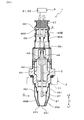
- FIG. 1 is a cross-sectional view showing a gas sensor according to an embodiment.
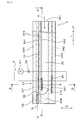
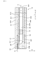
- FIG. 2 is a cross-sectional view showing a sensor element according to the embodiment.
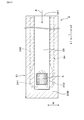
- FIG. 3 is a sectional view taken along line III-III of FIG. 2 showing the sensor element according to the embodiment.
- FIG. 4 is a sectional view taken along line IV-IV of FIG. 2 showing a sensor element according to the embodiment.
- FIG. 5 is a photograph of a cross section of the atmospheric electrode and the trap layer in the sensor element according to the embodiment.
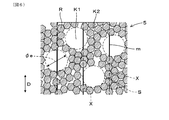
- FIG. 6 is a cross-sectional view schematically showing an enlarged cross section of the trap layer in the sensor element according to the embodiment.
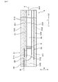
- FIG. 7 is a cross-sectional view showing another sensor element according to the embodiment, which has a different trap layer from that of FIG. 2.
- FIG. 8 is a cross-sectional view showing another sensor element according to the embodiment, which has a different trap layer from that of FIG. 2.
- FIG. 9 is a cross-sectional view showing another sensor element according to the embodiment, which has a different trap layer from that of FIG. 2.
- the gas sensor 1 of the present embodiment includes a sensor element 2 having a gas chamber 35 into which the exhaust gas G is introduced and an atmospheric duct 36 as an atmospheric duct 36 in which the atmosphere A is introduced. Inside the atmospheric duct 36, a trap layer 5 for capturing the toxic substance of the sensor element 2 is provided.
- the sensor element 2 includes a solid electrolyte 31 having ionic conductivity, a first insulator 33A and a second insulator 33B laminated on the solid electrolyte 31, and a solid electrolyte.
- the atmosphere provided at a position facing the exhaust electrode 311 (a position overlapping the exhaust electrode 311 in the stacking direction D) on the second surface 302 of the solid electrolyte body 31 and the exhaust electrode 311 provided on the first surface 301 of 31. It has an electrode 312.
- the exhaust electrode 311 is housed in the gas chamber 35 and is exposed to the exhaust gas G.
- the atmospheric electrode 312 is used in pairs with the exhaust electrode 311 and is housed in the atmospheric duct 36 and exposed to the atmosphere A.
- the gas chamber 35 is formed in a portion of the first insulator 33A facing the first surface 301 of the solid electrolyte body 31, and the exhaust gas G is introduced and the exhaust electrode 311 is housed.
- the atmospheric duct 36 is formed in a portion of the second insulator 33B facing the second surface 302 of the solid electrolyte body 31, and the atmospheric A is introduced and the atmospheric electrode 312 is housed.
- the gas sensor 1 of this embodiment will be described in detail below.
- the gas sensor 1 As shown in FIG. 1, the gas sensor 1 is arranged at the attachment port 71 of the exhaust pipe 7 of the internal combustion engine (engine) of the vehicle, and the exhaust gas G flowing through the exhaust pipe 7 is used as the detection target gas, and the oxygen concentration in the detection target gas and the like. Is used to detect.
- the gas sensor 1 can be used as an air-fuel ratio sensor (A / F sensor) for obtaining the air-fuel ratio in an internal combustion engine based on the oxygen concentration in the exhaust gas G, the unburned gas concentration, and the like.
- the gas sensor 1 can be used for various purposes for determining the oxygen concentration.
- a catalyst for purifying harmful substances in the exhaust gas G is arranged in the exhaust pipe 7, and the gas sensor 1 is arranged on either the upstream side or the downstream side of the catalyst in the flow direction of the exhaust gas G in the exhaust pipe 7. You can also do it.
- the gas sensor 1 can also be arranged in a pipe on the suction side of a supercharger that increases the density of air sucked by the internal combustion engine by using the exhaust gas G.
- the pipe in which the gas sensor 1 is arranged may be a pipe in the exhaust gas recirculation mechanism that recirculates a part of the exhaust gas G exhausted from the internal combustion engine to the exhaust pipe 7 to the intake pipe of the internal combustion engine.
- the air-fuel ratio sensor quantitatively and continuously ranges from a fuel-rich state in which the ratio of fuel to air is higher than the theoretical air-fuel ratio to a fuel lean state in which the ratio of fuel to air is lower than the theoretical air-fuel ratio. Can be detected.
- the diffusion rate of the exhaust gas G guided to the gas chamber 35 is throttled by the diffusion resistance unit (diffusion rate-determining unit) 32, oxygen ions (O) are formed between the exhaust electrode 311 and the atmospheric electrode 312.
- a predetermined voltage is applied to show the limit current characteristic in which the current corresponding to the movement amount of 2- ) is output.
- the air-fuel ratio sensor detects the air-fuel ratio on the fuel lean side, it is generated when oxygen contained in the exhaust gas G becomes ions and moves from the exhaust electrode 311 to the atmospheric electrode 312 via the solid electrolyte 31. Detect current. Further, when the air-fuel ratio sensor detects the air-fuel ratio on the fuel-rich side, it is solid from the atmospheric electrode 312 in order to react the unburned gas (hydrocarbon, carbon monoxide, hydrogen, etc.) contained in the exhaust gas G. The oxygen that has become ions moves to the exhaust electrode 311 via the electrolyte 31, and the current generated when the unburned gas and the oxygen react with each other is detected.
- the unburned gas hydrogen, carbon monoxide, hydrogen, etc.
- the air-fuel ratio detected by the air-fuel ratio sensor becomes the air-fuel ratio on the fuel-rich side
- a / F 10 (when the air mass / fuel mass is 10) or less
- a large amount of unburned gas is emitted.
- the atmospheric electrode 312 if the atmospheric electrode 312 is in a deteriorated state due to the adhesion of a toxic substance to the atmospheric electrode 312, the number of reaction points for decomposing and ionizing oxygen molecules in the atmospheric electrode 312 decreases, and the atmospheric electrode 312 decreases. It becomes difficult to send sufficient oxygen ions to the exhaust electrode 311 via the solid electrolyte 31. As a result, the activity of the atmospheric electrode 312 is reduced, so that the air-fuel ratio detection performance on the fuel-rich side is reduced.
- the trap layer 5 since the trap layer 5 is provided in the atmospheric duct 36, the trap layer 5 can capture the toxic substance in the atmosphere A introduced into the atmospheric duct 36. it can. As a result, a decrease in the number of reaction points of the atmospheric electrode 312 can be suppressed, and sufficient oxygen ions can be sent from the atmospheric electrode 312 to the exhaust electrode 311 via the solid electrolyte 31.
- the gas sensor 1 may be a sensor that detects the concentration of a specific gas component such as NOx (nitrogen oxide).
- NOx nitrogen oxide
- a pump electrode for pumping oxygen from the exhaust electrode 311 to the atmospheric electrode 312 by applying a voltage is arranged on the upstream side of the flow of the exhaust gas G in contact with the exhaust electrode 311.
- the atmospheric electrode 312 is also formed at a position facing the pump electrode via the solid electrolyte 31.
- the trap layer 5 is arranged in the atmospheric duct 36 to suppress the poisoning of the atmospheric electrode 312 and suppress the deterioration of the NOx concentration detection performance. it can.
- Poisonous substances in the atmosphere A that may poison the atmospheric electrode 312 include organic polymer gases such as siloxane gas generated in the engine room of a vehicle. Atmospheric gas outside the piping such as the exhaust pipe 7 in which the gas sensor 1 is arranged often includes the atmosphere A flowing from the engine room.
- the poisonous substance of the atmospheric electrode 312 refers to a substance having a property of adhering to the atmospheric electrode 312 and deteriorating the performance of the atmospheric electrode 312.
- the exhaust gas G may contain a substance that may poison the exhaust electrode 311. In this case, the toxic substance contained in the exhaust gas G is captured by the porous layer 37 provided on the surface of the sensor element 2, for example, as shown in FIG.
- the sensor element 2 of the present embodiment is formed in a long rectangular shape, and has a solid electrolyte body 31, an exhaust electrode 311 and an atmospheric electrode 312, a first insulator 33A, and a second insulator. It includes an insulator 33B, a gas chamber 35, an atmospheric duct 36, and a heating element 34.
- the sensor element 2 is a laminated type in which the insulators 33A and 33B and the heating element 34 are laminated on the solid electrolyte body 31.
- the long direction L of the sensor element 2 means the direction in which the sensor element 2 extends in a long shape. Further, the direction in which the solid electrolyte 31 and the insulators 33A and 33B are laminated, in other words, the solid electrolyte 31, the insulators 33A and 33B and the heating element 34 are laminated, orthogonal to the long direction L. The direction is called the stacking direction D. Further, the direction orthogonal to the long direction L and the stacking direction D is referred to as the width direction W. Further, in the long direction L of the sensor element 2, the side exposed to the exhaust gas G is referred to as the front end side L1, and the side opposite to the front end side L1 is referred to as the rear end side L2.
- the solid electrolyte 31 has the conductivity of oxygen ions (O 2- ) at a predetermined active temperature.
- the exhaust electrode 311 is provided on the first surface 301 of the solid electrolyte body 31 in contact with the exhaust gas G, and the atmospheric electrode 312 is provided on the second surface 302 of the solid electrolyte body 31 in contact with the atmosphere A. There is.
- the exhaust electrode 311 and the atmospheric electrode 312 face each other via the solid electrolyte 31 at the portion of the sensor element 2 in the long direction L on the distal end side L1 exposed to the exhaust gas G.
- a detection unit 21 consisting of an exhaust electrode 311 and an atmospheric electrode 312 and a portion of a solid electrolyte body 31 sandwiched between these electrodes 311, 312 is provided. It is formed.
- the first insulator 33A is laminated on the first surface 301 of the solid electrolyte body 31, and the second insulator 33B is laminated on the second surface 302 of the solid electrolyte body 31.
- the solid electrolyte 31 is composed of a zirconia-based oxide, contains zirconia as a main component (containing 50% by mass or more), and is a stabilized zirconia or a portion obtained by substituting a part of zirconia with a rare earth metal element or an alkaline earth metal element. Consists of stabilized zirconia. A portion of the zirconia constituting the solid electrolyte 31 can be replaced by yttria, scandia or calcia.
- the exhaust electrode 311 and the atmospheric electrode 312 contain platinum as a noble metal exhibiting catalytic activity for oxygen and a zirconia oxide as a co-material with the solid electrolyte 31.
- the co-material is the bond strength between the exhaust electrode 311 and the atmospheric electrode 312 formed by the electrode material and the solid electrolyte 31 when the paste-like electrode material is printed (coated) on the solid electrolyte 31 and both are fired. It is for maintaining.
- an electrode lead portion 313 for electrically connecting these electrodes 311, 312 to the outside of the gas sensor 1 is connected to the exhaust electrode 311 and the atmospheric electrode 312.
- the electrode lead portion 313 is pulled out to the portion of the sensor element 2 on the rear end side L2 in the long direction L.
- Gas chamber 35 As shown in FIGS. 2 and 3, a gas chamber 35 surrounded by the first insulator 33A and the solid electrolyte 31 is formed adjacent to the first surface 301 of the solid electrolyte 31.
- the gas chamber 35 is formed at a position of the first insulator 33A on the tip side L1 in the long direction L at a position for accommodating the exhaust electrode 311.
- the gas chamber 35 is formed as a space portion closed by the first insulator 33A, the diffusion resistance portion 32, and the solid electrolyte body 31.
- the exhaust gas G flowing in the exhaust pipe 7 passes through the diffusion resistance portion 32 and is introduced into the gas chamber 35.
- the diffusion resistance portion 32 of this embodiment is provided adjacent to the tip end side L1 of the gas chamber 35 in the elongated direction L.
- the diffusion resistance portion 32 is arranged in the introduction port opened adjacent to the tip end side L1 of the gas chamber 35 in the long direction L in the first insulator 33A.
- the diffusion resistance portion 32 is formed of a porous metal oxide such as alumina.
- the diffusion rate (flow rate) of the exhaust gas G introduced into the gas chamber 35 is determined by limiting the rate at which the exhaust gas G penetrates the pores in the diffusion resistance portion 32.
- the diffusion resistance portion 32 may be formed adjacent to both sides of the gas chamber 35 in the width direction W. In this case, the diffusion resistance portion 32 is arranged in the introduction port opened adjacent to both sides of the gas chamber 35 in the width direction W in the first insulator 33A.
- the diffusion resistance portion 32 can be formed not only by using a porous body but also by using a pinhole which is a small through hole communicated with the gas chamber 35.
- an atmospheric duct 36 surrounded by the second insulator 33B and the solid electrolyte 31 is formed adjacent to the second surface 302 of the solid electrolyte 31.
- the atmospheric duct 36 is formed from the portion of the second insulator 33B in the long direction L accommodating the atmospheric electrode 312 to the rear end position of the sensor element 2 in the long direction L exposed to the atmosphere A.
- a rear end opening as an atmosphere introduction portion 361 of the atmospheric duct 36 is formed.
- the atmospheric duct 36 is formed from the rear end opening to a position where it overlaps with the gas chamber 35 in the stacking direction D via the solid electrolyte body 31. Atmosphere A is introduced into the atmosphere duct 36 from the rear end opening.
- the cross-sectional area of the atmospheric duct 36 orthogonal to the long direction L is larger than the cross-sectional area of the gas chamber 35 orthogonal to the long direction L. Further, the thickness (width) of the atmospheric duct 36 in the stacking direction D is larger than the thickness (width) of the gas chamber 35 in the stacking direction D. Since the cross-sectional area, thickness, volume, etc. of the atmospheric duct 36 is larger than the cross-sectional area, thickness, volume, etc. of the gas chamber 35, oxygen in the atmosphere A for reacting the unburned gas in the exhaust electrode 311 is used. Sufficient supply can be provided from the atmospheric duct 36 to the exhaust electrode 311.
- Heating element 34 As shown in FIGS. 2 to 4, the heating element 34 is embedded in the second insulator 33B forming the atmospheric duct 36, and the heating element 341 that generates heat by energization and the heating element lead connected to the heating element 341. It has a part 342 and a portion 342.
- the heat generating portion 341 is arranged at a position where at least a part thereof overlaps with the exhaust electrode 311 and the atmospheric electrode 312 in the stacking direction D of the solid electrolyte body 31 and the insulators 33A and 33B.
- the heating element 34 has a heating element 341 that generates heat when energized, and a pair of heating element lead portions 342 that are connected to the rear end side L2 of the heating element 341 in the long direction L.
- the heat generating portion 341 is formed by a linear conductor portion meandering by a straight portion and a curved portion.
- the straight portion of the heat generating portion 341 of this embodiment is formed parallel to the elongated direction L.
- the heating element lead portion 342 is formed by a linear conductor portion.
- the resistance value per unit length of the heating element 341 is larger than the resistance value per unit length of the heating element lead unit 342.
- the heating element lead portion 342 is pulled out to the portion of the rear end side L2 in the long direction L.
- the heating element 34 contains a conductive metal material.
- the heat generating portion 341 of the present embodiment is formed in a shape meandering in the long direction L at the position of the tip side L1 in the long direction L in the heating element 34.
- the heat generating portion 341 may be formed in a meandering manner in the width direction W.
- the heat generating portion 341 is arranged at a position facing the exhaust electrode 311 and the atmospheric electrode 312 in the stacking direction D orthogonal to the long direction L. In other words, the heat generating portion 341 is arranged at a position of the sensor element 2 at the tip end side L1 in the long direction L at a position overlapping the exhaust electrode 311 and the atmospheric electrode 312 in the stacking direction D.
- the cross-sectional area of the heating element 341 is smaller than the cross-sectional area of the heating element lead portion 342, and the resistance value per unit length of the heating element lead portion 341 is higher than the resistance value per unit length of the heating element lead portion 342.
- This cross-sectional area means the cross-sectional area of the surfaces orthogonal to the extending direction of the heating element 341 and the heating element lead portion 342.
- the heating element 341 generates heat due to the energization from the heating element lead portion 342, so that the portion of the exhaust electrode 311 and the atmospheric electrode 312 and the solid electrolyte body 31 sandwiched between the electrodes 31 and 312 is targeted. Heated to temperature. At this time, in the long direction L of the solid electrolyte body 31, a temperature distribution is formed in which the temperature is increased by being heated by the heat generating portion 341, and the portion closer to the heat generating portion 341 is heated.
- the trap layer 5 is provided at a position where the temperature in the temperature distribution is 500 ° C. or higher. In other words, when the gas sensor 1 is used, the atmospheric electrode 312 provided with the trap layer 5 is heated to 500 ° C. or higher, and the trap layer 5 is also heated to 500 ° C. or higher.
- the portion of the atmospheric duct 36 facing the heat generating portion 341 is heated to 500 ° C. or higher. Further, the range of 15 mm from the tip of the sensor element 2 in the long direction L to the proximal end side L2 can be a portion heated to 500 ° C. or higher.
- the heat generation amount of the heat generation unit 341 can be set so that the heat generation center of the heat generation unit 341 is 550 to 650 ° C. Then, the region of 20% of the tip side L1 in the total length of the sensor element 2 in the long direction L can be a portion heated to 500 ° C. or higher.
- the trap layer 5 By providing the trap layer 5 at a portion of the sensor element 2 where the temperature becomes 500 ° C. or higher, it is possible to reduce the molecular weight of the toxic substance scattered in the vicinity of the trap layer 5. As a result, the toxic substance can be easily adsorbed (adhered) to the trap layer 5, and the toxic substance can be made difficult to separate from the trap layer 5.
- each insulator 33A, 33B As shown in FIGS. 2 and 3, the first insulator 33A forms the gas chamber 35, and the second insulator 33B forms the atmospheric duct 36 and embeds the heating element 34. ..
- the first insulator 33A and the second insulator 33B are formed of a metal oxide such as alumina (aluminum oxide).
- the insulators 33A and 33B are formed as a dense body through which the exhaust gas G or the atmosphere A cannot permeate, and the insulators 33A and 33B have almost no pores through which the gas can pass. ..
- Porous layer 37 As shown in FIG. 1, the entire circumference of the portion L1 on the tip side L1 in the long direction L of the sensor element 2 is porous to capture the toxic substance to the exhaust electrode 311 and the condensed water generated in the exhaust pipe 7. A layer 37 is provided.
- the porous layer 37 is formed of porous ceramics (metal oxide) such as alumina.
- the porosity of the porous layer 37 is larger than the porosity of the diffusion resistance portion 32, and the flow rate of the exhaust gas G that can permeate the porous layer 37 is the flow rate of the exhaust gas G that can permeate the diffusion resistance portion 32. More than.
- the gas sensor 1 includes a first insulator 42 that holds the sensor element 2, a housing 41 that holds the first insulator 42, and a second insulator connected to the first insulator 42. 43, a contact terminal 44 that is held by the second insulator 43 and comes into contact with the sensor element 2 is provided. Further, the gas sensor 1 is mounted on the element covers 45A and 45B which are mounted on the tip side L1 of the housing 41 and cover the tip side portion of the sensor element 2, and are mounted on the rear end side L2 of the housing 41 and are mounted on the second insulator 43. , The atmospheric covers 46A and 46B covering the contact terminals 44 and the like, and the bush 47 and the like for holding the lead wires 48 connected to the contact terminals 44 on the atmospheric covers 46A and 46B are provided.
- the tip end side portion of the sensor element 2 and the element covers 45A and 45B are arranged in the exhaust pipe 7 of the internal combustion engine.
- Gas passage holes 451 for passing exhaust gas G as a detection target gas are formed in the element covers 45A and 45B.
- the element covers 45A and 45B have a double structure of an inner cover 45A and an outer cover 45B that covers the inner cover 45A.
- the element covers 45A and 45B may have a single structure.
- the exhaust gas G flowing into the element covers 45A and 45B from the gas passage holes 451 of the element covers 45A and 45B passes through the porous layer 37 and the diffusion resistance portion 32 of the sensor element 2 and is guided to the exhaust electrode 311.
- the atmospheric covers 46A and 46B are arranged outside the exhaust pipe 7 of the internal combustion engine.
- the gas sensor 1 of this embodiment is for in-vehicle use, and the vehicle body in which the exhaust pipe 7 is arranged is connected to the engine room in which the internal combustion engine (engine) is arranged. Gases generated from various rubbers, resins, lubricants, etc. in the engine room are mixed with the atmosphere A and flow around the atmosphere covers 46A and 46B.
- the gas generated in the engine room becomes a poisonous substance that may poison the atmospheric electrode 312.
- Toxic substances generated in an engine room or the like include, for example, Si (silicon), S (sulfur) and the like.
- the atmospheric covers 46A and 46B of this embodiment are composed of a first cover 46A attached to the housing 41 and a second cover 46B covering the first cover 46A. Atmosphere passage holes 461 for passing the atmosphere A are formed in the first cover 46A and the second cover 46B. A water repellent filter 462 for preventing water from entering the first cover 46A is sandwiched between the first cover 46A and the second cover 46B at a position facing the air passage hole 461.
- the rear end opening of the sensor element 2 as the atmospheric introduction portion 361 of the atmospheric duct 36 is open to the space inside the atmospheric covers 46A and 46B.
- the atmosphere A existing around the atmosphere passage holes 461 of the atmosphere covers 46A and 46B is taken into the atmosphere covers 46A and 46B via the water repellent filter 462. Then, the atmosphere A that has passed through the water-repellent filter 462 flows into the atmosphere duct 36 from the rear end opening of the atmosphere duct 36 of the sensor element 2 as the atmosphere introduction portion 361, and is guided to the atmosphere electrode 312 in the atmosphere duct 36. Be taken.
- a plurality of contact terminals 44 are arranged in the second insulator 43 so as to be connected to each of the electrode lead portions 313 of the exhaust electrode 311 and the atmospheric electrode 312 and the heating element lead portion 342 of the heating element 34. Further, the lead wire 48 is connected to each of the contact terminals 44.
- the lead wire 48 in the gas sensor 1 is electrically connected to the sensor control device 6 that controls gas detection in the gas sensor 1.
- the sensor control device 6 performs electrical control on the gas sensor 1 in cooperation with an engine control device that controls combustion operation in the engine.
- the sensor control device 6 includes a current measuring circuit 61 for measuring the current flowing between the exhaust electrode 311 and the atmospheric electrode 312, a voltage applying circuit 62 for applying a voltage between the exhaust electrode 311 and the atmospheric electrode 312, and a heating element.
- An energization circuit or the like for energizing 34 is formed.
- the sensor control device 6 may be built in the engine control device.
- the trap layer 5 is formed of a porous body of an insulating metal oxide.
- the trap layer 5 of this embodiment is formed of a porous body of ⁇ -alumina (Al 2 O 3 , trigonal aluminum oxide).
- the trap layer 5 is formed by bonding ⁇ -alumina particles as metal oxides to each other by firing.
- ⁇ -alumina particles having a particle size of 0.5 to 10 ⁇ m in 90% by mass or more of the whole can be used.
- Alumina hydrate obtained by hydrolysis of aluminum alkoxide is generally used as a fine-grained alumina raw material having a large material specific surface area.
- Alumina hydrate becomes ⁇ -alumina stable at high temperature through intermediate products such as ⁇ -alumina and ⁇ -alumina by heating at high temperature, but ⁇ -alumina grows as grains during ⁇ transition.
- the specific surface area becomes smaller.
- ⁇ -alumina is used for the porous layer 37 that captures the toxic substance in the exhaust gas G because the specific surface area is relatively large and crystal transformation does not occur at the temperature of the exhaust gas G.
- ⁇ -alumina which has a stable crystal structure even at the firing temperature of the sensor element 2, is used for the trap layer 5 that captures the toxic substance in the atmosphere A.
- the crystal structure of the trap layer 5 can be stably maintained when the trap layer 5 is fired together with the sensor element 2.
- ⁇ -alumina or ⁇ -alumina is used for the trap layer 5
- the metal oxide particles constituting the trap layer 5 when the trap layer 5 is fired, the metal oxide particles constituting the trap layer 5, the bonding interface between the metal oxide particles, etc.
- cracks, peeling, etc. may occur.
- the porous layer 37 is provided on the surface of the sensor element 2 by a dipping method or an injection method after the sensor element 2 is fired.
- the porous layer 37 may have a crystal structure that can withstand the temperature of the exhaust gas G without being fired together with the sensor element 2.
- the trap layer 5 is laminated inside the sensor element 2 together with the solid electrolyte 31, the insulators 33A and 33B, the exhaust electrode 311 and the atmospheric electrode 312, and becomes an intermediate of the sensor element 2 before firing. After that, it is fired together with the sensor element 2. Therefore, it is preferable to use ⁇ -alumina for the trap layer 5, which can withstand the firing temperature of the sensor element 2.
- FIG. 5 shows a cross section of the trap layer 5 formed on the surface of the atmospheric electrode 312 in the solid electrolyte body 31. Further, FIG. 6 shows an enlarged cross section of the trap layer 5. As shown in each figure, a gap through which a gas can pass is formed in the trap layer 5. More specifically, the trap layer 5 is formed between the macropores K1 formed by the uneven distribution of the metal oxide particles R and the metal oxide particles R smaller than the macropores K1. Interparticle voids K2 are formed.
- the macro pore K1 can be formed by using a burning agent S such as a resin that is burned when the sensor element 2 is fired.
- the burning agent S is also called a pore-increasing agent. More specifically, in the formation of the trap layer 5, a paste material containing metal oxide particles R, a burning agent S, and a solvent (water, etc.) is used, and the sensor element 2 coated with this paste material is used. It is fired. At this time, in the paste material, the burnout agent S is burnt down, and macropores K1 as cavities are formed in the portion where the burnout agent S is arranged.
- the macropores K1 and the interparticle voids K2 may be formed in a state of being communicated with each other.
- the macropore K1 of the present embodiment is formed in a state close to a spherical shape by being formed by using the spherical burning agent S.
- the macropores K1 there are macropores K1 that are adjacent to each other and are connected to each other.
- the macropore K1 may be formed in a columnar shape, a needle shape, or the like.
- the gap in the trap layer 5 may be formed only by the macropores K1 or the interparticle voids K2.
- the macropore K1 can also be formed by a method that does not use the burning agent S.
- the toxic substance contained in the atmosphere A is trapped (captured) in the macropores K1 or the interparticle voids K2 when passing through the macropores K1 and the interparticle voids K2 formed in the trap layer 5. , The entire trap layer 5 cannot be passed. Then, oxygen or the like in the atmosphere A passes through the macropores K1 and the interparticle voids K2 formed in the trap layer 5 and reaches the atmospheric electrode 312.
- the trap layer 5 is provided so as to cover the surface of the atmospheric electrode 312 provided on the second surface 302 of the solid electrolyte body 31.
- the trap layer 5 is for suppressing the poisonous substance from adhering to the atmospheric electrode 312 and causing the atmospheric electrode 312 to be poisoned (deteriorated).
- the trap layer 5 covers the atmospheric electrode 312 and is provided in contact with the second surface 302 of the solid electrolyte body 31.
- the trap layer 5 is provided so as not to fill the flow path of the atmospheric duct 36, in other words, to not block the atmospheric duct 36. Further, in other words, the trap layer 5 is provided in a state of being separated from the second insulator 33B forming the atmospheric duct 36.
- the atmospheric duct 36 is continuously formed even in the portion where the trap layer 5 is provided, and the entire surface of the trap layer 5 is exposed to the atmosphere A in the atmospheric duct 36. Since the flow path of the atmospheric duct 36 is not filled with the trap layer 5, a state is formed in which the atmosphere A in the atmospheric duct 36 can easily reach the atmospheric electrode 312 through the trap layer 5.
- the trap layer 5 can be formed so as to cover the entire atmosphere electrode 312. Further, the trap layer 5 can be formed so as to cover a part of the atmospheric electrode 312. In this case, for example, the trap layer 5 can be formed so as to cover the central portion of the surface of the atmospheric electrode 312, or can be formed so as to cover more than half of the surface of the atmospheric electrode 312.
- the trap layer 5 can be provided in the atmospheric duct 36 at a position L2 on the rear end side of the long direction L from the position where the atmospheric electrode 312 is provided.
- the trap layer 5 is the surface of at least one of the solid electrolyte 31 and the second insulator 33B forming the atmospheric duct 36 inside the atmospheric duct 36 without filling the flow path of the atmospheric duct 36.
- the state in which the flow path of the atmospheric duct 36 is not filled means that the trap layer 5 arranged in a part of the long direction L of the atmospheric duct 36 is arranged in a part of the cross section orthogonal to the long direction L of the atmospheric duct 36. It refers to the state of being done.
- FIG. 1 the state in which the flow path of the atmospheric duct 36 is not filled.
- the trap layer 5 is provided on the second surface 302 of the solid electrolyte body 31 at the position of the rear end side L2 of the long direction L with respect to the atmospheric electrode 312. In this case, when the atmosphere A flowing from the rear end side L2 to the front end side L1 passes around the trap layer 5, the toxic substance in the atmosphere A is captured by the trap layer 5.
- the trap layers 5 can be provided at a plurality of locations in the atmospheric duct 36.
- the trap layer 5 can be provided at different positions in the longitudinal direction L on the second surface 302 of the solid electrolyte 31 and the inner surface of the second insulator 33B.
- the atmosphere A in the atmospheric duct 36 can meander around the trap layer 5 and flow from the rear end side L2 to the front end side L1. Then, the toxic substance in the atmosphere A passing around the trap layer 5 can be captured by the trap layer 5.
- the trap layer 5 is provided so as to extend from the position covering the atmospheric electrode 312 on the second surface 302 of the solid electrolyte body 31 to the rear end side L2 in the long direction L. Good.
- the length a2 of the rear end side portion 52 of the trap layer 5 formed so as to project from the rear end 316 of the atmospheric electrode 312 to the rear end side L2 of the long direction L is the atmospheric electrode 312.
- the length a1 of the tip side portion 51 of the trap layer 5 formed so as to project from the tip end 315 to the tip end side L1 in the long direction L can be made longer than the length a1 in the long direction L. In this case, the toxic substance in the atmosphere A passing through the atmospheric duct 36 can be easily captured by the trap layer 5.
- the trap layer 5 can be provided in a state of blocking a part of the flow path in the long direction L of the atmospheric duct 36.
- a state in which a part of the flow path of the atmospheric duct 36 is blocked means that the trap layer 5 arranged in a part of the long direction L of the atmospheric duct 36 is the entire cross section orthogonal to the long direction L of the atmospheric duct 36. It refers to the state in which it is placed in.
- the trap layer 5 can be provided adjacent to the position of the rear end side L2 of the long direction L with respect to the atmospheric electrode 312.
- the trap layer 5 can maintain the state of being heated to a temperature of 500 ° C. or higher, and the trap layer 5 can capture the toxic substance in the reference gas A.
- the amount of gaps in the porous body constituting the trap layer 5 can be increased to facilitate the passage of the reference gas A through the trap layer 5.
- the average film thickness (average thickness) d of the trap layer 5 on the surface of the atmospheric electrode 312 can be 10 ⁇ m or more and 500 ⁇ m or less.
- the average film thickness d can be an average value of these film thicknesses by measuring the film thicknesses of 10 to 100 parts of the trap layer 5 on the surface of the atmospheric electrode 312. It is preferable that the trap layer 5 on the surface of the atmospheric electrode 312 is formed to have a film thickness as uniform as possible.
- the trap layer 5 on the surface of the atmospheric electrode 312 is less than 10 ⁇ m, the trap layer 5 is thin and the ability to adsorb (adhere) toxic substances may be insufficient.
- the average film thickness d of the trap layer 5 on the surface of the atmospheric electrode 312 exceeds 500 ⁇ m, the trap layer 5 is thick and the ventilation gas resistance of the trap layer 5 increases, in other words, the gas permeation performance is improved. It becomes low, and there is a possibility that a sufficient amount of atmosphere A cannot be supplied to the atmosphere electrode 312.
- the average pore diameter ⁇ e of the macropores K1 can be made larger than the particle size of the ⁇ -alumina particles as the metal oxide. Then, the size of the macropores K1, the number of formations per unit volume, and the like are changed to change the ease of capturing the poisonous substance in the trap layer 5 and the ease of passing through the atmosphere (air) A. can do.
- the average pore diameter ⁇ e of the macropores K1 in the trap layer 5 can be 0.4 ⁇ m or more. With this configuration, the trap layer 5 can be made less likely to be clogged by capturing the toxic substance. Further, the average pore diameter ⁇ e of the macro pore K1 can be, for example, 10 ⁇ m or less, which is smaller than the average film thickness d of the trap layer 5.
- the size of the macropores K1 is proportional to the size of the burnout agent S used. Therefore, the average pore diameter ⁇ e of the macropores K1 can be changed by changing the size of the burnout agent S used. Further, by matching the sizes of the plurality of burnout agents S to be used, the sizes of the formed macropores K1 can also be matched.
- the macropore K1 can be formed in the range of 1 to 5 ⁇ m by using, for example, the burnout agent S in the range of 1 to 5 ⁇ m.
- the average pore diameter ⁇ e of the macro pores K1 can be an average value of the pore diameters of 10 to 100 macro pores K1 appearing in the cross section obtained by cutting the trap layer 5.
- the average pore diameter ⁇ e of the macropores K1 is obtained by observing the cross section of the trap layer 5 cut by an SEM (scanning electron microscope) or the like and measuring the maximum length of a plurality of macropores K1 included in the unit cross-sectional area. It can be calculated by averaging the lengths.
- Each measurement line X in the cross section of the trap layer 5 can be set at equal intervals in the cross section of the trap layer 5.
- the length m of the macropore K1 can be observed using an SEM (scanning electron microscope).
- the diffusion bending coefficient f when observing a cross section obtained by cutting the trap layer 5, a plurality of measurement lines X in this cross section are set, and the sum of the lengths m of the macropores K1 in each measurement line X is ⁇ m in the trap layer. It can be expressed as the average value of the values divided by the length (thickness) d of 5.
- the length d of the trap layer 5 can be measured for each measurement line X.
- the intermediate of the sensor element 2 When the intermediate of the sensor element 2 is fired, if the paste material constituting the trap layer 5 contains the burning agent S, the burning agent S is burned when the intermediate is heated. Then, macropores K1 are formed in the intermediate where the burning agent S is arranged, and the sensor element 2 is formed.
- the sensor element 2 may use a reference electrode instead of using the atmospheric duct 36 and the atmospheric electrode 312.
- a reference electrode used as a pair with the exhaust electrode 311 is arranged at a position on the second surface 302 of the solid electrolyte body 31 of the sensor element 2 so as to overlap the exhaust electrode 311 in the stacking direction D. Can be done.
- the reference electrode is embedded between the second surface 302 of the solid electrolyte 31 and the surface of the second insulator 33B.
- the atmosphere introduction path for introducing the atmosphere A into the reference electrode shall be the electrode lead portion 313 of the reference electrode arranged at the boundary position between the second surface 302 of the solid electrolyte 31 and the surface of the second insulator 33B. (See Fig. 2).
- oxygen in the atmosphere A existing at the rear end position of the sensor element 2 moves the electrode lead portion 313 of the reference electrode from the rear end side L2 of the long direction L to the front end side L1 and becomes the reference electrode. Be supplied.
- the trap layer 5 can be provided around the electrode lead portion 313 at the rear end position of the sensor element 2 in the long direction L.
- the trap layer 5 is provided in the atmospheric duct 36 so as to cover the atmospheric electrode 312 provided on the second surface 302 of the solid electrolyte body 31.
- a large amount of oxygen is required for the air electrode 312 in order to make the air electrode 312.
- the atmospheric electrode 312 may not function sufficiently and a current output indicating the air-fuel ratio on the fuel-rich side may not be sufficiently obtained. Then, the detection accuracy of the air-fuel ratio on the fuel-rich side may be deteriorated.
- the trap layer 5 is provided so as to cover the atmospheric electrode 312 without filling the atmospheric duct 36, so that the atmosphere is maintained while the supply amount of the atmosphere A to the atmospheric electrode 312 is secured.
- the electrode 312 can be prevented from being deteriorated by the toxic substance. As a result, the accuracy of detecting the air-fuel ratio on the fuel-rich side by the gas sensor 1 can be improved.
- the gas sensor 1 of the present embodiment it is possible to capture the toxic substance and suppress the deterioration of the atmospheric electrode 312, and to supply the required oxygen to the atmospheric duct 36 and the atmospheric electrode 312. In addition, the accuracy of gas detection by the gas sensor 1 can be improved.
- the average film thickness d, the average pore diameter ⁇ e, and the diffusion bending coefficient f of the trap layer 5 were shown in the embodiment, and were measured by the method shown in the embodiment.
- the trap layer 5 in the test sample is provided so as to cover the entire atmosphere electrode 312 on the second surface 302 of the solid electrolyte body 31, and is longer than the location where the atmosphere electrode 312 is arranged in the atmosphere duct 36. It may be provided at the position of L2 on the rear end side.
- the former case is shown as "electrode position” and the latter case is shown as “duct position”. In some cases, it is provided at both the "electrode position" and the "duct position”.
- the atmosphere A taken into the atmosphere duct 36 of the test sample of the gas sensor contained siloxane gas having a concentration of 10 ppm (volume ratio).
- the siloxane gas refers to a compound having a siloxane bond (Si—O—Si bond).
- Table 1 shows the configurations of test products 1 to 8 and comparative products 1 to 3, and the evaluation of the output current as a result of the confirmation test.
- the output current was lower than -0.7 mA because the temperature at the position where the trap layer 5 was arranged was as low as 300 ° C.
- the average film thickness d of the trap layer 5 was as large as 1000 ⁇ m, and the diffusion bending coefficient f of the trap layer 5 was as small as 0.1 or less, so that an output current could not be obtained.
- the average pore diameter ⁇ e of the trap layer 5 is as small as 0.3 ⁇ m, and the diffusion bending coefficient f of the trap layer 5 is as small as 0.1 or less, so that the trap layer 5 is clogged.
- the output current was lower than -0.7mA.
- the evaluation of the output current was "poor" or "-", and it was found that the output accuracy of the gas sensor could not be maintained.
- the temperature of the trap layer 5 the average film thickness d, the average pore diameter ⁇ e, and the diffusion bending coefficient f were all appropriate, and the evaluation of the output current was “good”. Then, it was found that the trap layer 5 appropriately adsorbs the toxic substance and can maintain high output accuracy of the gas sensor.
- the present disclosure is not limited to the embodiment, and it is possible to configure a different embodiment without departing from the gist thereof.
- the present disclosure includes various modifications, modifications within an equal range, and the like.
- the technical concept of the present disclosure also includes combinations, forms, etc. of various components assumed from the present disclosure.
Abstract
This gas sensor is equipped with a sensor element (2). The sensor element (2) comprises: a solid electrolyte (31); a first insulating body (33A) and second insulating body (33B) laminated on the solid electrolyte (31); an exhaust electrode (311) and air electrode (312) provided to the solid electrolyte (31); a gas chamber (35) for introducing exhaust gas (G) to the exhaust electrode (311) and formed on the first insulating body (33A); and an air duct (36) for introducing air (A) to the air electrode (312) and formed on the second insulating body (33B). In the interior of the air duct (36), a trap layer (5) for trapping a toxic substances of the sensor element (2) is provided.
Description
本出願は、2019年3月28日に出願された日本の特許出願番号2019-063492号に基づくものであり、その記載内容を援用する。
This application is based on Japanese Patent Application No. 2019-063492 filed on March 28, 2019, and the contents of the description are incorporated.
本開示は、大気導入経路を有するセンサ素子を備えるガスセンサに関する。
The present disclosure relates to a gas sensor including a sensor element having an atmospheric introduction path.
ガスセンサは、内燃機関の排気管等に配置され、排気管を流れる排ガスを検出対象ガスとして、内燃機関の空燃比、排ガスの酸素濃度等を求めるために使用される。ガスセンサには、酸素イオン伝導性を有する固体電解質体と、固体電解質体の表面に設けられた一対の電極とを有するセンサ素子が用いられる。一方の電極は、排ガスに晒される排気電極として用いられ、他方の電極は、排気電極との間において酸素イオンを伝導させる対極としての大気電極として用いられる。このようなセンサ素子としては、例えば、特許文献1に記載された積層型ガスセンサ素子がある。
The gas sensor is arranged in the exhaust pipe of the internal combustion engine, etc., and is used to obtain the air-fuel ratio of the internal combustion engine, the oxygen concentration of the exhaust gas, etc., using the exhaust gas flowing through the exhaust pipe as the detection target gas. As the gas sensor, a sensor element having a solid electrolyte having oxygen ion conductivity and a pair of electrodes provided on the surface of the solid electrolyte is used. One electrode is used as an exhaust electrode exposed to exhaust gas, and the other electrode is used as an atmospheric electrode as a counter electrode for conducting oxygen ions with the exhaust electrode. As such a sensor element, for example, there is a laminated gas sensor element described in Patent Document 1.
排ガス中には、排気電極に付着して排気電極を被毒(劣化)させる被毒物質が含まれる。そのため、センサ素子において、排気電極に排ガスが導入される経路には、被毒物質を捕獲することができる多孔質保護層が設けられている。一方、大気電極に大気が導入される経路には、多孔質保護層は設けられていない。大気中に含まれる物質が大気電極に付着したとしても、大気電極の性能に大きな影響は与えないと考えているためである。
The exhaust gas contains a poisonous substance that adheres to the exhaust electrode and poisons (deteriorates) the exhaust electrode. Therefore, in the sensor element, a porous protective layer capable of capturing the toxic substance is provided in the path where the exhaust gas is introduced into the exhaust electrode. On the other hand, the porous protective layer is not provided in the path through which the atmosphere is introduced into the atmospheric electrodes. This is because even if a substance contained in the atmosphere adheres to the atmospheric electrode, it does not have a significant effect on the performance of the atmospheric electrode.
しかし、大気電極へ多量の大気が必要とされる場合等においては、大気電極に、より高い性能が要求され、大気電極に必要な性能を維持するために、大気電極を被毒(劣化)から保護する必要があることが判明した。このような場合としては、例えば、ガスセンサが、内燃機関の空燃比を検出する空燃比センサとして使用される場合に、内燃機関の空燃比が、理論空燃比に比べて極度な燃料リッチの状態になったとき等が考えられる。
However, when a large amount of air is required for the atmospheric electrode, the atmospheric electrode is required to have higher performance, and in order to maintain the performance required for the atmospheric electrode, the atmospheric electrode is detoxified (deteriorated). It turns out that it needs to be protected. In such a case, for example, when the gas sensor is used as an air-fuel ratio sensor for detecting the air-fuel ratio of the internal combustion engine, the air-fuel ratio of the internal combustion engine becomes extremely fuel-rich as compared with the theoretical air-fuel ratio. When it becomes, etc. can be considered.
本開示は、被毒物質を捕獲して、大気導入経路へ必要とする酸素を供給することができるガスセンサを提供しようとして得られたものである。
The present disclosure was obtained in an attempt to provide a gas sensor capable of capturing a toxic substance and supplying the required oxygen to the atmospheric introduction path.
本開示の一態様は、大気が導入される大気導入経路を有するセンサ素子を備え、
前記大気導入経路には、前記センサ素子の被毒物質を捕獲するためのトラップ層が設けられている、ガスセンサにある。 One aspect of the present disclosure comprises a sensor element having an atmosphere introduction path into which the atmosphere is introduced.
The atmosphere introduction path is in a gas sensor provided with a trap layer for capturing the toxic substance of the sensor element.
前記一態様のガスセンサにおいては、センサ素子の大気導入経路にトラップ層が設けられている。これにより、センサ素子の大気導入経路に、大気中における多量の酸素が必要になった場合においても、大気中の被毒物質をトラップ層によって捕獲して、多量の酸素を大気導入経路へ供給することができる。
In the gas sensor of the above aspect, a trap layer is provided in the atmosphere introduction path of the sensor element. As a result, even when a large amount of oxygen in the atmosphere is required for the atmospheric introduction path of the sensor element, the toxic substance in the atmosphere is captured by the trap layer and a large amount of oxygen is supplied to the atmospheric introduction path. be able to.
それ故、前記一態様のガスセンサによれば、被毒物質を捕獲して、大気導入経路へ必要とする酸素を供給することができる。
Therefore, according to the gas sensor of the above aspect, it is possible to capture the toxic substance and supply the required oxygen to the atmospheric introduction path.
なお、本開示の一態様において示す各構成要素のカッコ書きの符号は、実施形態における図中の符号との対応関係を示すが、各構成要素を実施形態の内容のみに限定するものではない。
Note that the reference numerals in parentheses of each component shown in one aspect of the present disclosure indicate the correspondence with the reference numerals in the drawings in the embodiment, but each component is not limited to the content of the embodiment.
本開示についての目的、特徴、利点等は、添付の図面を参照する後記の詳細な記述によって、より明確になる。本開示の図面を以下に示す。
図1は、実施形態にかかる、ガスセンサを示す断面図である。
図2は、実施形態にかかる、センサ素子を示す断面図である。
図3は、実施形態にかかる、センサ素子を示す、図2のIII-III断面図である。
図4は、実施形態にかかる、センサ素子を示す、図2のIV-IV断面図である。
図5は、実施形態にかかる、センサ素子における大気電極及びトラップ層の断面の写真である。
図6は、実施形態にかかる、センサ素子におけるトラップ層の断面を拡大して模式的に示す断面図である。
図7は、実施形態にかかる、図2の場合とトラップ層が異なる他のセンサ素子を示す断面図である。
図8は、実施形態にかかる、図2の場合とトラップ層が異なる他のセンサ素子を示す断面図である。
図9は、実施形態にかかる、図2の場合とトラップ層が異なる他のセンサ素子を示す断面図である。
The objectives, features, advantages, etc. of the present disclosure will be clarified by the detailed description below with reference to the accompanying drawings. The drawings of the present disclosure are shown below.
FIG. 1 is a cross-sectional view showing a gas sensor according to an embodiment. FIG. 2 is a cross-sectional view showing a sensor element according to the embodiment. FIG. 3 is a sectional view taken along line III-III of FIG. 2 showing the sensor element according to the embodiment. FIG. 4 is a sectional view taken along line IV-IV of FIG. 2 showing a sensor element according to the embodiment. FIG. 5 is a photograph of a cross section of the atmospheric electrode and the trap layer in the sensor element according to the embodiment. FIG. 6 is a cross-sectional view schematically showing an enlarged cross section of the trap layer in the sensor element according to the embodiment. FIG. 7 is a cross-sectional view showing another sensor element according to the embodiment, which has a different trap layer from that of FIG. 2. FIG. 8 is a cross-sectional view showing another sensor element according to the embodiment, which has a different trap layer from that of FIG. 2. FIG. 9 is a cross-sectional view showing another sensor element according to the embodiment, which has a different trap layer from that of FIG. 2.
前述したガスセンサにかかる好ましい実施形態について、図面を参照して説明する。
<実施形態>
本形態のガスセンサ1は、図1~図4に示すように、排ガスGが導入されるガス室35及び大気Aが導入される大気導入経路としての大気ダクト36を有するセンサ素子2を備える。大気ダクト36の内部には、センサ素子2の被毒物質を捕獲するためのトラップ層5が設けられている。 A preferred embodiment of the gas sensor described above will be described with reference to the drawings.
<Embodiment>
As shown in FIGS. 1 to 4, thegas sensor 1 of the present embodiment includes a sensor element 2 having a gas chamber 35 into which the exhaust gas G is introduced and an atmospheric duct 36 as an atmospheric duct 36 in which the atmosphere A is introduced. Inside the atmospheric duct 36, a trap layer 5 for capturing the toxic substance of the sensor element 2 is provided.
<実施形態>
本形態のガスセンサ1は、図1~図4に示すように、排ガスGが導入されるガス室35及び大気Aが導入される大気導入経路としての大気ダクト36を有するセンサ素子2を備える。大気ダクト36の内部には、センサ素子2の被毒物質を捕獲するためのトラップ層5が設けられている。 A preferred embodiment of the gas sensor described above will be described with reference to the drawings.
<Embodiment>
As shown in FIGS. 1 to 4, the
図2~図4に示すように、センサ素子2は、イオン伝導性を有する固体電解質体31と、固体電解質体31に積層された第1絶縁体33A及び第2絶縁体33Bと、固体電解質体31の第1表面301に設けられた排気電極311と、固体電解質体31の第2表面302における、排気電極311と対向する位置(排気電極311と積層方向Dに重なる位置)に設けられた大気電極312とを有する。排気電極311は、ガス室35内に収容されて排ガスGに晒される。大気電極312は、排気電極311と対になって使用されるものであり、大気ダクト36内に収容されて大気Aに晒される。
As shown in FIGS. 2 to 4, the sensor element 2 includes a solid electrolyte 31 having ionic conductivity, a first insulator 33A and a second insulator 33B laminated on the solid electrolyte 31, and a solid electrolyte. The atmosphere provided at a position facing the exhaust electrode 311 (a position overlapping the exhaust electrode 311 in the stacking direction D) on the second surface 302 of the solid electrolyte body 31 and the exhaust electrode 311 provided on the first surface 301 of 31. It has an electrode 312. The exhaust electrode 311 is housed in the gas chamber 35 and is exposed to the exhaust gas G. The atmospheric electrode 312 is used in pairs with the exhaust electrode 311 and is housed in the atmospheric duct 36 and exposed to the atmosphere A.
ガス室35は、第1絶縁体33Aにおける、固体電解質体31の第1表面301と対向する部位に形成されており、排ガスGが導入されるとともに排気電極311を収容している。大気ダクト36は、第2絶縁体33Bにおける、固体電解質体31の第2表面302と対向する部位に形成されており、大気Aが導入されるとともに大気電極312を収容している。
The gas chamber 35 is formed in a portion of the first insulator 33A facing the first surface 301 of the solid electrolyte body 31, and the exhaust gas G is introduced and the exhaust electrode 311 is housed. The atmospheric duct 36 is formed in a portion of the second insulator 33B facing the second surface 302 of the solid electrolyte body 31, and the atmospheric A is introduced and the atmospheric electrode 312 is housed.
以下に、本形態のガスセンサ1について詳説する。
(ガスセンサ1)
図1に示すように、ガスセンサ1は、車両の内燃機関(エンジン)の排気管7の取付口71に配置され、排気管7を流れる排ガスGを検出対象ガスとして、検出対象ガスにおける酸素濃度等を検出するために用いられる。ガスセンサ1は、排ガスGにおける酸素濃度、未燃ガス濃度等に基づいて、内燃機関における空燃比を求める空燃比センサ(A/Fセンサ)として用いることができる。また、ガスセンサ1は、空燃比センサ以外にも、酸素濃度を求める種々の用途として用いることができる。 Thegas sensor 1 of this embodiment will be described in detail below.
(Gas sensor 1)
As shown in FIG. 1, thegas sensor 1 is arranged at the attachment port 71 of the exhaust pipe 7 of the internal combustion engine (engine) of the vehicle, and the exhaust gas G flowing through the exhaust pipe 7 is used as the detection target gas, and the oxygen concentration in the detection target gas and the like. Is used to detect. The gas sensor 1 can be used as an air-fuel ratio sensor (A / F sensor) for obtaining the air-fuel ratio in an internal combustion engine based on the oxygen concentration in the exhaust gas G, the unburned gas concentration, and the like. In addition to the air-fuel ratio sensor, the gas sensor 1 can be used for various purposes for determining the oxygen concentration.
(ガスセンサ1)
図1に示すように、ガスセンサ1は、車両の内燃機関(エンジン)の排気管7の取付口71に配置され、排気管7を流れる排ガスGを検出対象ガスとして、検出対象ガスにおける酸素濃度等を検出するために用いられる。ガスセンサ1は、排ガスGにおける酸素濃度、未燃ガス濃度等に基づいて、内燃機関における空燃比を求める空燃比センサ(A/Fセンサ)として用いることができる。また、ガスセンサ1は、空燃比センサ以外にも、酸素濃度を求める種々の用途として用いることができる。 The
(Gas sensor 1)
As shown in FIG. 1, the
排気管7には、排ガスG中の有害物質を浄化するための触媒が配置されており、ガスセンサ1は、排気管7における排ガスGの流れ方向において、触媒の上流側又は下流側のいずれに配置することもできる。また、ガスセンサ1は、排ガスGを利用して内燃機関が吸入する空気の密度を高める過給機の吸入側の配管に配置することもできる。また、ガスセンサ1を配置する配管は、内燃機関から排気管7に排気される排ガスGの一部を、内燃機関の吸気管に再循環させる排気再循環機構における配管とすることもできる。
A catalyst for purifying harmful substances in the exhaust gas G is arranged in the exhaust pipe 7, and the gas sensor 1 is arranged on either the upstream side or the downstream side of the catalyst in the flow direction of the exhaust gas G in the exhaust pipe 7. You can also do it. Further, the gas sensor 1 can also be arranged in a pipe on the suction side of a supercharger that increases the density of air sucked by the internal combustion engine by using the exhaust gas G. Further, the pipe in which the gas sensor 1 is arranged may be a pipe in the exhaust gas recirculation mechanism that recirculates a part of the exhaust gas G exhausted from the internal combustion engine to the exhaust pipe 7 to the intake pipe of the internal combustion engine.
空燃比センサは、理論空燃比と比べて空気に対する燃料の割合が多い燃料リッチの状態から、理論空燃比と比べて空気に対する燃料の割合が少ない燃料リーンの状態まで定量的に連続して空燃比を検出することができるものである。空燃比センサにおいては、拡散抵抗部(拡散律速部)32によって、ガス室35へ導かれる排ガスGの拡散速度が絞られる際に、排気電極311と大気電極312との間に、酸素イオン(O2-)の移動量に応じた電流が出力される限界電流特性を示すための所定の電圧が印加される。
The air-fuel ratio sensor quantitatively and continuously ranges from a fuel-rich state in which the ratio of fuel to air is higher than the theoretical air-fuel ratio to a fuel lean state in which the ratio of fuel to air is lower than the theoretical air-fuel ratio. Can be detected. In the air-fuel ratio sensor, when the diffusion rate of the exhaust gas G guided to the gas chamber 35 is throttled by the diffusion resistance unit (diffusion rate-determining unit) 32, oxygen ions (O) are formed between the exhaust electrode 311 and the atmospheric electrode 312. A predetermined voltage is applied to show the limit current characteristic in which the current corresponding to the movement amount of 2- ) is output.
空燃比センサにおいて、燃料リーン側の空燃比を検出する際には、排ガスGに含まれる酸素が、イオンとなって排気電極311から固体電解質体31を介して大気電極312へ移動する際に生じる電流を検出する。また、空燃比センサにおいて、燃料リッチ側の空燃比を検出する際には、排ガスGに含まれる未燃ガス(炭化水素、一酸化炭素、水素等)を反応させるために、大気電極312から固体電解質体31を介して排気電極311へイオンとなった酸素が移動し、未燃ガスと酸素とが反応する際に生じる電流を検出する。
When the air-fuel ratio sensor detects the air-fuel ratio on the fuel lean side, it is generated when oxygen contained in the exhaust gas G becomes ions and moves from the exhaust electrode 311 to the atmospheric electrode 312 via the solid electrolyte 31. Detect current. Further, when the air-fuel ratio sensor detects the air-fuel ratio on the fuel-rich side, it is solid from the atmospheric electrode 312 in order to react the unburned gas (hydrocarbon, carbon monoxide, hydrogen, etc.) contained in the exhaust gas G. The oxygen that has become ions moves to the exhaust electrode 311 via the electrolyte 31, and the current generated when the unburned gas and the oxygen react with each other is detected.
空燃比センサにおいて検出する空燃比が、例えば、A/F=10(空気質量/燃料質量が10である場合)以下等の、より燃料リッチ側の空燃比になるときには、大量の未燃ガスを燃焼させるために、大気電極312から固体電解質体31を介して排気電極311へ、十分な量の酸素を移動させることが必要になる。この場合に、大気電極312に被毒物質が付着することによって、大気電極312が劣化した状態にあると、大気電極312における酸素分子を分解しイオン化する反応点の数が低下し、大気電極312から固体電解質体31を介して排気電極311へ十分な酸素イオンを送り込むことが難しくなる。これにより、大気電極312の活性低下によって、燃料リッチ側の空燃比の検出性能が低下する。
When the air-fuel ratio detected by the air-fuel ratio sensor becomes the air-fuel ratio on the fuel-rich side, for example, A / F = 10 (when the air mass / fuel mass is 10) or less, a large amount of unburned gas is emitted. In order to burn, it is necessary to transfer a sufficient amount of oxygen from the atmospheric electrode 312 to the exhaust electrode 311 via the solid electrolyte 31. In this case, if the atmospheric electrode 312 is in a deteriorated state due to the adhesion of a toxic substance to the atmospheric electrode 312, the number of reaction points for decomposing and ionizing oxygen molecules in the atmospheric electrode 312 decreases, and the atmospheric electrode 312 decreases. It becomes difficult to send sufficient oxygen ions to the exhaust electrode 311 via the solid electrolyte 31. As a result, the activity of the atmospheric electrode 312 is reduced, so that the air-fuel ratio detection performance on the fuel-rich side is reduced.
本形態のセンサ素子2においては、大気ダクト36内にトラップ層5が設けられていることにより、このトラップ層5によって、大気ダクト36に導入された大気A中の被毒物質を捕獲することができる。これにより、大気電極312の反応点の数の低下を抑制して、大気電極312から固体電解質体31を介して排気電極311へ十分な酸素イオンを送り込むことができる。
In the sensor element 2 of the present embodiment, since the trap layer 5 is provided in the atmospheric duct 36, the trap layer 5 can capture the toxic substance in the atmosphere A introduced into the atmospheric duct 36. it can. As a result, a decrease in the number of reaction points of the atmospheric electrode 312 can be suppressed, and sufficient oxygen ions can be sent from the atmospheric electrode 312 to the exhaust electrode 311 via the solid electrolyte 31.
(他のガスセンサ1)
ガスセンサ1は、NOx(窒素酸化物)等の特定ガス成分の濃度を検出するセンサとしてもよい。NOxセンサにおいては、排気電極311に接触する排ガスGの流れの上流側に、電圧の印加によって排気電極311から大気電極312へ酸素をポンピングするポンプ電極が配置される。大気電極312はポンプ電極に対して固体電解質体31を介して対向する位置にも形成される。ガスセンサ1をNOxセンサとして用いる場合には、大気ダクト36内にトラップ層5が配置されていることにより、大気電極312の被毒を抑制して、NOx濃度の検出性能の低下を抑制することができる。 (Other gas sensor 1)
Thegas sensor 1 may be a sensor that detects the concentration of a specific gas component such as NOx (nitrogen oxide). In the NOx sensor, a pump electrode for pumping oxygen from the exhaust electrode 311 to the atmospheric electrode 312 by applying a voltage is arranged on the upstream side of the flow of the exhaust gas G in contact with the exhaust electrode 311. The atmospheric electrode 312 is also formed at a position facing the pump electrode via the solid electrolyte 31. When the gas sensor 1 is used as a NOx sensor, the trap layer 5 is arranged in the atmospheric duct 36 to suppress the poisoning of the atmospheric electrode 312 and suppress the deterioration of the NOx concentration detection performance. it can.
ガスセンサ1は、NOx(窒素酸化物)等の特定ガス成分の濃度を検出するセンサとしてもよい。NOxセンサにおいては、排気電極311に接触する排ガスGの流れの上流側に、電圧の印加によって排気電極311から大気電極312へ酸素をポンピングするポンプ電極が配置される。大気電極312はポンプ電極に対して固体電解質体31を介して対向する位置にも形成される。ガスセンサ1をNOxセンサとして用いる場合には、大気ダクト36内にトラップ層5が配置されていることにより、大気電極312の被毒を抑制して、NOx濃度の検出性能の低下を抑制することができる。 (Other gas sensor 1)
The
(被毒物質)
大気電極312を被毒させるおそれがある、大気A中の被毒物質には、車両のエンジンルーム等において発生するシロキサンガス等の有機高分子ガスがある。ガスセンサ1が配置された排気管7等の配管の外部における雰囲気ガスには、エンジンルームから流れる大気Aが含まれることが多い。大気電極312の被毒物質とは、大気電極312に付着して、大気電極312の性能を劣化させる性質を有する物質のことをいう。また、排ガスGには、排気電極311を被毒させるおそれがある物質が含まれることがある。この場合には、排ガスGに含まれる被毒物質は、例えば、図1に示すように、センサ素子2の表面に設けられた多孔質層37によって捕獲される。 (Poisonous substance)
Poisonous substances in the atmosphere A that may poison theatmospheric electrode 312 include organic polymer gases such as siloxane gas generated in the engine room of a vehicle. Atmospheric gas outside the piping such as the exhaust pipe 7 in which the gas sensor 1 is arranged often includes the atmosphere A flowing from the engine room. The poisonous substance of the atmospheric electrode 312 refers to a substance having a property of adhering to the atmospheric electrode 312 and deteriorating the performance of the atmospheric electrode 312. Further, the exhaust gas G may contain a substance that may poison the exhaust electrode 311. In this case, the toxic substance contained in the exhaust gas G is captured by the porous layer 37 provided on the surface of the sensor element 2, for example, as shown in FIG.
大気電極312を被毒させるおそれがある、大気A中の被毒物質には、車両のエンジンルーム等において発生するシロキサンガス等の有機高分子ガスがある。ガスセンサ1が配置された排気管7等の配管の外部における雰囲気ガスには、エンジンルームから流れる大気Aが含まれることが多い。大気電極312の被毒物質とは、大気電極312に付着して、大気電極312の性能を劣化させる性質を有する物質のことをいう。また、排ガスGには、排気電極311を被毒させるおそれがある物質が含まれることがある。この場合には、排ガスGに含まれる被毒物質は、例えば、図1に示すように、センサ素子2の表面に設けられた多孔質層37によって捕獲される。 (Poisonous substance)
Poisonous substances in the atmosphere A that may poison the
(センサ素子2)
図2~図4に示すように、本形態のセンサ素子2は、長尺の長方形状に形成されており、固体電解質体31、排気電極311及び大気電極312、第1絶縁体33A、第2絶縁体33B、ガス室35、大気ダクト36及び発熱体34を備える。センサ素子2は、固体電解質体31に、各絶縁体33A,33B及び発熱体34が積層された積層タイプのものである。 (Sensor element 2)
As shown in FIGS. 2 to 4, thesensor element 2 of the present embodiment is formed in a long rectangular shape, and has a solid electrolyte body 31, an exhaust electrode 311 and an atmospheric electrode 312, a first insulator 33A, and a second insulator. It includes an insulator 33B, a gas chamber 35, an atmospheric duct 36, and a heating element 34. The sensor element 2 is a laminated type in which the insulators 33A and 33B and the heating element 34 are laminated on the solid electrolyte body 31.
図2~図4に示すように、本形態のセンサ素子2は、長尺の長方形状に形成されており、固体電解質体31、排気電極311及び大気電極312、第1絶縁体33A、第2絶縁体33B、ガス室35、大気ダクト36及び発熱体34を備える。センサ素子2は、固体電解質体31に、各絶縁体33A,33B及び発熱体34が積層された積層タイプのものである。 (Sensor element 2)
As shown in FIGS. 2 to 4, the
本形態において、センサ素子2の長尺方向Lとは、センサ素子2が長尺形状に延びる方向のことをいう。また、長尺方向Lに直交し、固体電解質体31と各絶縁体33A,33Bとが積層された方向、換言すれば、固体電解質体31、各絶縁体33A,33B及び発熱体34が積層された方向を、積層方向Dという。また、長尺方向Lと積層方向Dとに直交する方向を、幅方向Wという。また、センサ素子2の長尺方向Lにおいて、排ガスGに晒される側を先端側L1といい、先端側L1の反対側を後端側L2という。
In this embodiment, the long direction L of the sensor element 2 means the direction in which the sensor element 2 extends in a long shape. Further, the direction in which the solid electrolyte 31 and the insulators 33A and 33B are laminated, in other words, the solid electrolyte 31, the insulators 33A and 33B and the heating element 34 are laminated, orthogonal to the long direction L. The direction is called the stacking direction D. Further, the direction orthogonal to the long direction L and the stacking direction D is referred to as the width direction W. Further, in the long direction L of the sensor element 2, the side exposed to the exhaust gas G is referred to as the front end side L1, and the side opposite to the front end side L1 is referred to as the rear end side L2.
(固体電解質体31、排気電極311及び大気電極312)
図2及び図3に示すように、固体電解質体31は、所定の活性温度において、酸素イオン(O2-)の伝導性を有するものである。排気電極311は、固体電解質体31における、排ガスGが接触する第1表面301に設けられており、大気電極312は、固体電解質体31における、大気Aが接触する第2表面302に設けられている。排気電極311と大気電極312とは、センサ素子2の長尺方向Lにおける、排ガスGに晒される先端側L1の部位において、固体電解質体31を介して互いに対向している。センサ素子2の長尺方向Lの先端側L1の部位には、排気電極311及び大気電極312と、これらの電極311,312の間に挟まれた固体電解質体31の部分とによる検知部21が形成されている。第1絶縁体33Aは、固体電解質体31の第1表面301に積層されており、第2絶縁体33Bは、固体電解質体31の第2表面302に積層されている。 (Solid electrolyte 31, exhaust electrode 311 and atmospheric electrode 312)
As shown in FIGS. 2 and 3, thesolid electrolyte 31 has the conductivity of oxygen ions (O 2- ) at a predetermined active temperature. The exhaust electrode 311 is provided on the first surface 301 of the solid electrolyte body 31 in contact with the exhaust gas G, and the atmospheric electrode 312 is provided on the second surface 302 of the solid electrolyte body 31 in contact with the atmosphere A. There is. The exhaust electrode 311 and the atmospheric electrode 312 face each other via the solid electrolyte 31 at the portion of the sensor element 2 in the long direction L on the distal end side L1 exposed to the exhaust gas G. At the portion of the sensor element 2 on the tip side L1 in the long direction L, a detection unit 21 consisting of an exhaust electrode 311 and an atmospheric electrode 312 and a portion of a solid electrolyte body 31 sandwiched between these electrodes 311, 312 is provided. It is formed. The first insulator 33A is laminated on the first surface 301 of the solid electrolyte body 31, and the second insulator 33B is laminated on the second surface 302 of the solid electrolyte body 31.
図2及び図3に示すように、固体電解質体31は、所定の活性温度において、酸素イオン(O2-)の伝導性を有するものである。排気電極311は、固体電解質体31における、排ガスGが接触する第1表面301に設けられており、大気電極312は、固体電解質体31における、大気Aが接触する第2表面302に設けられている。排気電極311と大気電極312とは、センサ素子2の長尺方向Lにおける、排ガスGに晒される先端側L1の部位において、固体電解質体31を介して互いに対向している。センサ素子2の長尺方向Lの先端側L1の部位には、排気電極311及び大気電極312と、これらの電極311,312の間に挟まれた固体電解質体31の部分とによる検知部21が形成されている。第1絶縁体33Aは、固体電解質体31の第1表面301に積層されており、第2絶縁体33Bは、固体電解質体31の第2表面302に積層されている。 (
As shown in FIGS. 2 and 3, the
固体電解質体31は、ジルコニア系酸化物からなり、ジルコニアを主成分とし(50質量%以上含有し)、希土類金属元素又はアルカリ土類金属元素によってジルコニアの一部を置換させた安定化ジルコニア又は部分安定化ジルコニアからなる。固体電解質体31を構成するジルコニアの一部は、イットリア、スカンジア又はカルシアによって置換することができる。
The solid electrolyte 31 is composed of a zirconia-based oxide, contains zirconia as a main component (containing 50% by mass or more), and is a stabilized zirconia or a portion obtained by substituting a part of zirconia with a rare earth metal element or an alkaline earth metal element. Consists of stabilized zirconia. A portion of the zirconia constituting the solid electrolyte 31 can be replaced by yttria, scandia or calcia.
排気電極311及び大気電極312は、酸素に対する触媒活性を示す貴金属としての白金、及び固体電解質体31との共材としてのジルコニア系酸化物を含有している。共材は、固体電解質体31にペースト状の電極材料を印刷(塗布)して両者を焼成する際に、電極材料によって形成される排気電極311及び大気電極312と固体電解質体31との結合強度を維持するためのものである。
The exhaust electrode 311 and the atmospheric electrode 312 contain platinum as a noble metal exhibiting catalytic activity for oxygen and a zirconia oxide as a co-material with the solid electrolyte 31. The co-material is the bond strength between the exhaust electrode 311 and the atmospheric electrode 312 formed by the electrode material and the solid electrolyte 31 when the paste-like electrode material is printed (coated) on the solid electrolyte 31 and both are fired. It is for maintaining.
図2に示すように、排気電極311及び大気電極312には、これらの電極311,312をガスセンサ1の外部と電気接続するための電極リード部313が接続されている。電極リード部313は、センサ素子2の長尺方向Lの後端側L2の部位まで引き出されている。
As shown in FIG. 2, an electrode lead portion 313 for electrically connecting these electrodes 311, 312 to the outside of the gas sensor 1 is connected to the exhaust electrode 311 and the atmospheric electrode 312. The electrode lead portion 313 is pulled out to the portion of the sensor element 2 on the rear end side L2 in the long direction L.
(ガス室35)
図2及び図3に示すように、固体電解質体31の第1表面301には、第1絶縁体33Aと固体電解質体31とに囲まれたガス室35が隣接して形成されている。ガス室35は、第1絶縁体33Aの長尺方向Lの先端側L1の部位において、排気電極311を収容する位置に形成されている。ガス室35は、第1絶縁体33Aと拡散抵抗部32と固体電解質体31とによって閉じられた空間部として形成されている。排気管7内を流れる排ガスGは、拡散抵抗部32を通過してガス室35内に導入される。 (Gas chamber 35)
As shown in FIGS. 2 and 3, agas chamber 35 surrounded by the first insulator 33A and the solid electrolyte 31 is formed adjacent to the first surface 301 of the solid electrolyte 31. The gas chamber 35 is formed at a position of the first insulator 33A on the tip side L1 in the long direction L at a position for accommodating the exhaust electrode 311. The gas chamber 35 is formed as a space portion closed by the first insulator 33A, the diffusion resistance portion 32, and the solid electrolyte body 31. The exhaust gas G flowing in the exhaust pipe 7 passes through the diffusion resistance portion 32 and is introduced into the gas chamber 35.
図2及び図3に示すように、固体電解質体31の第1表面301には、第1絶縁体33Aと固体電解質体31とに囲まれたガス室35が隣接して形成されている。ガス室35は、第1絶縁体33Aの長尺方向Lの先端側L1の部位において、排気電極311を収容する位置に形成されている。ガス室35は、第1絶縁体33Aと拡散抵抗部32と固体電解質体31とによって閉じられた空間部として形成されている。排気管7内を流れる排ガスGは、拡散抵抗部32を通過してガス室35内に導入される。 (Gas chamber 35)
As shown in FIGS. 2 and 3, a
(拡散抵抗部32)
本形態の拡散抵抗部32は、ガス室35の長尺方向Lの先端側L1に隣接して設けられている。拡散抵抗部32は、第1絶縁体33Aにおいて、ガス室35の長尺方向Lの先端側L1に隣接して開口された導入口内に配置されている。拡散抵抗部32は、アルミナ等の多孔質の金属酸化物によって形成されている。ガス室35に導入される排ガスGの拡散速度(流量)は、排ガスGが拡散抵抗部32における気孔を透過する速度が制限されることによって決定される。 (Diffusion resistance unit 32)
Thediffusion resistance portion 32 of this embodiment is provided adjacent to the tip end side L1 of the gas chamber 35 in the elongated direction L. The diffusion resistance portion 32 is arranged in the introduction port opened adjacent to the tip end side L1 of the gas chamber 35 in the long direction L in the first insulator 33A. The diffusion resistance portion 32 is formed of a porous metal oxide such as alumina. The diffusion rate (flow rate) of the exhaust gas G introduced into the gas chamber 35 is determined by limiting the rate at which the exhaust gas G penetrates the pores in the diffusion resistance portion 32.
本形態の拡散抵抗部32は、ガス室35の長尺方向Lの先端側L1に隣接して設けられている。拡散抵抗部32は、第1絶縁体33Aにおいて、ガス室35の長尺方向Lの先端側L1に隣接して開口された導入口内に配置されている。拡散抵抗部32は、アルミナ等の多孔質の金属酸化物によって形成されている。ガス室35に導入される排ガスGの拡散速度(流量)は、排ガスGが拡散抵抗部32における気孔を透過する速度が制限されることによって決定される。 (Diffusion resistance unit 32)
The
拡散抵抗部32は、ガス室35の幅方向Wの両側に隣接して形成してもよい。この場合には、拡散抵抗部32は、第1絶縁体33Aにおいて、ガス室35の幅方向Wの両側に隣接して開口された導入口内に配置される。なお、拡散抵抗部32は、多孔質体を用いて形成する以外にも、ガス室35に連通された小さな貫通穴であるピンホールを用いて形成することもできる。
The diffusion resistance portion 32 may be formed adjacent to both sides of the gas chamber 35 in the width direction W. In this case, the diffusion resistance portion 32 is arranged in the introduction port opened adjacent to both sides of the gas chamber 35 in the width direction W in the first insulator 33A. The diffusion resistance portion 32 can be formed not only by using a porous body but also by using a pinhole which is a small through hole communicated with the gas chamber 35.
(大気ダクト36)
図2~図4に示すように、固体電解質体31の第2表面302には、第2絶縁体33Bと固体電解質体31とに囲まれた大気ダクト36が隣接して形成されている。大気ダクト36は、第2絶縁体33Bにおける、大気電極312を収容する長尺方向Lの部位から、センサ素子2の長尺方向Lにおける、大気Aに晒される後端位置まで形成されている。センサ素子2の長尺方向Lの後端位置には、大気ダクト36の大気導入部361としての後端開口部が形成されている。大気ダクト36は、後端開口部から固体電解質体31を介してガス室35と積層方向Dに重なる位置まで形成されている。大気ダクト36には、後端開口部から大気Aが導入される。 (Atmospheric duct 36)
As shown in FIGS. 2 to 4, anatmospheric duct 36 surrounded by the second insulator 33B and the solid electrolyte 31 is formed adjacent to the second surface 302 of the solid electrolyte 31. The atmospheric duct 36 is formed from the portion of the second insulator 33B in the long direction L accommodating the atmospheric electrode 312 to the rear end position of the sensor element 2 in the long direction L exposed to the atmosphere A. At the rear end position of the sensor element 2 in the long direction L, a rear end opening as an atmosphere introduction portion 361 of the atmospheric duct 36 is formed. The atmospheric duct 36 is formed from the rear end opening to a position where it overlaps with the gas chamber 35 in the stacking direction D via the solid electrolyte body 31. Atmosphere A is introduced into the atmosphere duct 36 from the rear end opening.
図2~図4に示すように、固体電解質体31の第2表面302には、第2絶縁体33Bと固体電解質体31とに囲まれた大気ダクト36が隣接して形成されている。大気ダクト36は、第2絶縁体33Bにおける、大気電極312を収容する長尺方向Lの部位から、センサ素子2の長尺方向Lにおける、大気Aに晒される後端位置まで形成されている。センサ素子2の長尺方向Lの後端位置には、大気ダクト36の大気導入部361としての後端開口部が形成されている。大気ダクト36は、後端開口部から固体電解質体31を介してガス室35と積層方向Dに重なる位置まで形成されている。大気ダクト36には、後端開口部から大気Aが導入される。 (Atmospheric duct 36)
As shown in FIGS. 2 to 4, an
大気ダクト36における、長尺方向Lに直交する断面の断面積は、ガス室35における、長尺方向Lに直交する断面の断面積よりも大きい。また、大気ダクト36の積層方向Dの厚み(幅)は、ガス室35の積層方向Dの厚み(幅)よりも大きい。大気ダクト36の断面積、厚み、体積等が、ガス室35の断面積、厚み、体積等よりも大きいことにより、排気電極311における未燃ガスを反応させるための、大気A中の酸素を、大気ダクト36から排気電極311へ十分に供給することができる。
The cross-sectional area of the atmospheric duct 36 orthogonal to the long direction L is larger than the cross-sectional area of the gas chamber 35 orthogonal to the long direction L. Further, the thickness (width) of the atmospheric duct 36 in the stacking direction D is larger than the thickness (width) of the gas chamber 35 in the stacking direction D. Since the cross-sectional area, thickness, volume, etc. of the atmospheric duct 36 is larger than the cross-sectional area, thickness, volume, etc. of the gas chamber 35, oxygen in the atmosphere A for reacting the unburned gas in the exhaust electrode 311 is used. Sufficient supply can be provided from the atmospheric duct 36 to the exhaust electrode 311.
(発熱体34)
図2~図4に示すように、発熱体34は、大気ダクト36を形成する第2絶縁体33B内に埋設されており、通電によって発熱する発熱部341と、発熱部341に繋がる発熱体リード部342とを有する。発熱部341は、固体電解質体31と各絶縁体33A,33Bとの積層方向Dにおいて、少なくとも一部が排気電極311及び大気電極312に重なる位置に配置されている。 (Heating element 34)
As shown in FIGS. 2 to 4, theheating element 34 is embedded in the second insulator 33B forming the atmospheric duct 36, and the heating element 341 that generates heat by energization and the heating element lead connected to the heating element 341. It has a part 342 and a portion 342. The heat generating portion 341 is arranged at a position where at least a part thereof overlaps with the exhaust electrode 311 and the atmospheric electrode 312 in the stacking direction D of the solid electrolyte body 31 and the insulators 33A and 33B.
図2~図4に示すように、発熱体34は、大気ダクト36を形成する第2絶縁体33B内に埋設されており、通電によって発熱する発熱部341と、発熱部341に繋がる発熱体リード部342とを有する。発熱部341は、固体電解質体31と各絶縁体33A,33Bとの積層方向Dにおいて、少なくとも一部が排気電極311及び大気電極312に重なる位置に配置されている。 (Heating element 34)
As shown in FIGS. 2 to 4, the
また、発熱体34は、通電によって発熱する発熱部341と、発熱部341の、長尺方向Lの後端側L2に繋がる一対の発熱体リード部342とを有する。発熱部341は、直線部分及び曲線部分によって蛇行する線状の導体部によって形成されている。本形態の発熱部341の直線部分は、長尺方向Lに平行に形成されている。発熱体リード部342は、直線状の導体部によって形成されている。発熱部341の単位長さ当たりの抵抗値は、発熱体リード部342の単位長さ当たりの抵抗値よりも大きい。発熱体リード部342は、長尺方向Lの後端側L2の部位まで引き出されている。発熱体34は、導電性を有する金属材料を含有している。
Further, the heating element 34 has a heating element 341 that generates heat when energized, and a pair of heating element lead portions 342 that are connected to the rear end side L2 of the heating element 341 in the long direction L. The heat generating portion 341 is formed by a linear conductor portion meandering by a straight portion and a curved portion. The straight portion of the heat generating portion 341 of this embodiment is formed parallel to the elongated direction L. The heating element lead portion 342 is formed by a linear conductor portion. The resistance value per unit length of the heating element 341 is larger than the resistance value per unit length of the heating element lead unit 342. The heating element lead portion 342 is pulled out to the portion of the rear end side L2 in the long direction L. The heating element 34 contains a conductive metal material.
図4に示すように、本形態の発熱部341は、発熱体34における長尺方向Lの先端側L1の位置において、長尺方向Lに蛇行する形状に形成されている。なお、発熱部341は、幅方向Wに蛇行して形成されていてもよい。発熱部341は、長尺方向Lに直交する積層方向Dにおいて、排気電極311及び大気電極312に対向する位置に配置されている。換言すれば、発熱部341は、センサ素子2の長尺方向Lの先端側L1の部位において、排気電極311及び大気電極312に対して積層方向Dに重なる位置に配置されている。
As shown in FIG. 4, the heat generating portion 341 of the present embodiment is formed in a shape meandering in the long direction L at the position of the tip side L1 in the long direction L in the heating element 34. The heat generating portion 341 may be formed in a meandering manner in the width direction W. The heat generating portion 341 is arranged at a position facing the exhaust electrode 311 and the atmospheric electrode 312 in the stacking direction D orthogonal to the long direction L. In other words, the heat generating portion 341 is arranged at a position of the sensor element 2 at the tip end side L1 in the long direction L at a position overlapping the exhaust electrode 311 and the atmospheric electrode 312 in the stacking direction D.
発熱部341の断面積は、発熱体リード部342の断面積よりも小さく、発熱部341の単位長さ当たりの抵抗値は、発熱体リード部342の単位長さ当たりの抵抗値よりも高い。この断面積とは、発熱部341及び発熱体リード部342が延びる方向に直交する面の断面積のことをいう。そして、一対の発熱体リード部342に電圧が印加されると、発熱部341がジュール熱によって発熱し、この発熱によって、検知部21の周辺が加熱される。
The cross-sectional area of the heating element 341 is smaller than the cross-sectional area of the heating element lead portion 342, and the resistance value per unit length of the heating element lead portion 341 is higher than the resistance value per unit length of the heating element lead portion 342. This cross-sectional area means the cross-sectional area of the surfaces orthogonal to the extending direction of the heating element 341 and the heating element lead portion 342. When a voltage is applied to the pair of heating element lead units 342, the heating unit 341 generates heat due to Joule heat, and the heat generated heats the periphery of the detection unit 21.
発熱体リード部342からの通電によって発熱部341が発熱することにより、排気電極311、大気電極312、及び固体電解質体31における、各電極311,312の間に挟まれた部分が、目標とする温度に加熱される。このとき、固体電解質体31の長尺方向Lにおいては、発熱部341によって加熱されることによる温度分布であって発熱部341に近い部位ほど高温になる温度分布が形成される。トラップ層5は、温度分布における温度が500℃以上になる位置に設けられている。換言すれば、ガスセンサ1の使用時において、トラップ層5が設けられた大気電極312は500℃以上に加熱されており、トラップ層5も500℃以上に加熱される。
The heating element 341 generates heat due to the energization from the heating element lead portion 342, so that the portion of the exhaust electrode 311 and the atmospheric electrode 312 and the solid electrolyte body 31 sandwiched between the electrodes 31 and 312 is targeted. Heated to temperature. At this time, in the long direction L of the solid electrolyte body 31, a temperature distribution is formed in which the temperature is increased by being heated by the heat generating portion 341, and the portion closer to the heat generating portion 341 is heated. The trap layer 5 is provided at a position where the temperature in the temperature distribution is 500 ° C. or higher. In other words, when the gas sensor 1 is used, the atmospheric electrode 312 provided with the trap layer 5 is heated to 500 ° C. or higher, and the trap layer 5 is also heated to 500 ° C. or higher.
大気ダクト36における、発熱部341に対向する部位は、500℃以上に加熱される。また、センサ素子2の長尺方向Lの先端から基端側L2へ15mmの範囲内は、500℃以上に加熱される部位とすることができる。発熱部341の発熱量は、発熱部341の発熱中心が550~650℃になるようにすることができる。そして、センサ素子2の長尺方向Lの全長における、先端側L1の20%の領域は、500℃以上に加熱される部位とすることができる。
The portion of the atmospheric duct 36 facing the heat generating portion 341 is heated to 500 ° C. or higher. Further, the range of 15 mm from the tip of the sensor element 2 in the long direction L to the proximal end side L2 can be a portion heated to 500 ° C. or higher. The heat generation amount of the heat generation unit 341 can be set so that the heat generation center of the heat generation unit 341 is 550 to 650 ° C. Then, the region of 20% of the tip side L1 in the total length of the sensor element 2 in the long direction L can be a portion heated to 500 ° C. or higher.
センサ素子2における温度が500℃以上になる部位にトラップ層5を設けることにより、トラップ層5の付近に飛散する被毒物質を低分子化させることができる。これにより、被毒物質がトラップ層5に吸着(付着)しやすくするとともに、トラップ層5から被毒物質が離脱しにくくすることができる。
By providing the trap layer 5 at a portion of the sensor element 2 where the temperature becomes 500 ° C. or higher, it is possible to reduce the molecular weight of the toxic substance scattered in the vicinity of the trap layer 5. As a result, the toxic substance can be easily adsorbed (adhered) to the trap layer 5, and the toxic substance can be made difficult to separate from the trap layer 5.
(各絶縁体33A,33B)
図2及び図3に示すように、第1絶縁体33Aは、ガス室35を形成するものであり、第2絶縁体33Bは、大気ダクト36を形成するとともに発熱体34を埋設するものである。第1絶縁体33A及び第2絶縁体33Bは、アルミナ(酸化アルミニウム)等の金属酸化物によって形成されている。各絶縁体33A,33Bは、排ガスG又は大気Aが透過することができない緻密体として形成されており、各絶縁体33A,33Bには、気体が通過することができる気孔がほとんど形成されていない。 (Each insulator 33A, 33B)
As shown in FIGS. 2 and 3, thefirst insulator 33A forms the gas chamber 35, and the second insulator 33B forms the atmospheric duct 36 and embeds the heating element 34. .. The first insulator 33A and the second insulator 33B are formed of a metal oxide such as alumina (aluminum oxide). The insulators 33A and 33B are formed as a dense body through which the exhaust gas G or the atmosphere A cannot permeate, and the insulators 33A and 33B have almost no pores through which the gas can pass. ..
図2及び図3に示すように、第1絶縁体33Aは、ガス室35を形成するものであり、第2絶縁体33Bは、大気ダクト36を形成するとともに発熱体34を埋設するものである。第1絶縁体33A及び第2絶縁体33Bは、アルミナ(酸化アルミニウム)等の金属酸化物によって形成されている。各絶縁体33A,33Bは、排ガスG又は大気Aが透過することができない緻密体として形成されており、各絶縁体33A,33Bには、気体が通過することができる気孔がほとんど形成されていない。 (Each
As shown in FIGS. 2 and 3, the
(多孔質層37)
図1に示すように、センサ素子2の長尺方向Lの先端側L1の部位の全周には、排気電極311に対する被毒物質、排気管7内に生じる凝縮水等を捕獲するための多孔質層37が設けられている。多孔質層37は、アルミナ等の多孔質のセラミックス(金属酸化物)によって形成されている。多孔質層37の気孔率は、拡散抵抗部32の気孔率よりも大きく、多孔質層37を透過することができる排ガスGの流量は、拡散抵抗部32を透過することができる排ガスGの流量よりも多い。 (Porous layer 37)
As shown in FIG. 1, the entire circumference of the portion L1 on the tip side L1 in the long direction L of thesensor element 2 is porous to capture the toxic substance to the exhaust electrode 311 and the condensed water generated in the exhaust pipe 7. A layer 37 is provided. The porous layer 37 is formed of porous ceramics (metal oxide) such as alumina. The porosity of the porous layer 37 is larger than the porosity of the diffusion resistance portion 32, and the flow rate of the exhaust gas G that can permeate the porous layer 37 is the flow rate of the exhaust gas G that can permeate the diffusion resistance portion 32. More than.
図1に示すように、センサ素子2の長尺方向Lの先端側L1の部位の全周には、排気電極311に対する被毒物質、排気管7内に生じる凝縮水等を捕獲するための多孔質層37が設けられている。多孔質層37は、アルミナ等の多孔質のセラミックス(金属酸化物)によって形成されている。多孔質層37の気孔率は、拡散抵抗部32の気孔率よりも大きく、多孔質層37を透過することができる排ガスGの流量は、拡散抵抗部32を透過することができる排ガスGの流量よりも多い。 (Porous layer 37)
As shown in FIG. 1, the entire circumference of the portion L1 on the tip side L1 in the long direction L of the
(ガスセンサ1の他の構成)
図1に示すように、ガスセンサ1は、センサ素子2の他に、センサ素子2を保持する第1インシュレータ42、第1インシュレータ42を保持するハウジング41、第1インシュレータ42に連結された第2インシュレータ43、第2インシュレータ43に保持されてセンサ素子2に接触する接点端子44を備える。また、ガスセンサ1は、ハウジング41の先端側L1の部分に装着されてセンサ素子2の先端側部分を覆う素子カバー45A,45B、ハウジング41の後端側L2の部分に装着されて第2インシュレータ43、接点端子44等を覆う大気カバー46A,46B、接点端子44に繋がるリード線48を大気カバー46A,46Bに保持するためのブッシュ47等を備える。 (Other configurations of gas sensor 1)
As shown in FIG. 1, in addition to thesensor element 2, the gas sensor 1 includes a first insulator 42 that holds the sensor element 2, a housing 41 that holds the first insulator 42, and a second insulator connected to the first insulator 42. 43, a contact terminal 44 that is held by the second insulator 43 and comes into contact with the sensor element 2 is provided. Further, the gas sensor 1 is mounted on the element covers 45A and 45B which are mounted on the tip side L1 of the housing 41 and cover the tip side portion of the sensor element 2, and are mounted on the rear end side L2 of the housing 41 and are mounted on the second insulator 43. , The atmospheric covers 46A and 46B covering the contact terminals 44 and the like, and the bush 47 and the like for holding the lead wires 48 connected to the contact terminals 44 on the atmospheric covers 46A and 46B are provided.
図1に示すように、ガスセンサ1は、センサ素子2の他に、センサ素子2を保持する第1インシュレータ42、第1インシュレータ42を保持するハウジング41、第1インシュレータ42に連結された第2インシュレータ43、第2インシュレータ43に保持されてセンサ素子2に接触する接点端子44を備える。また、ガスセンサ1は、ハウジング41の先端側L1の部分に装着されてセンサ素子2の先端側部分を覆う素子カバー45A,45B、ハウジング41の後端側L2の部分に装着されて第2インシュレータ43、接点端子44等を覆う大気カバー46A,46B、接点端子44に繋がるリード線48を大気カバー46A,46Bに保持するためのブッシュ47等を備える。 (Other configurations of gas sensor 1)
As shown in FIG. 1, in addition to the
センサ素子2の先端側部分及び素子カバー45A,45Bは、内燃機関の排気管7内に配置される。素子カバー45A,45Bには、検出対象ガスとしての排ガスGを通過させるためのガス通過孔451が形成されている。素子カバー45A,45Bは、インナーカバー45Aと、インナーカバー45Aを覆うアウターカバー45Bとの二重構造を有する。素子カバー45A,45Bは、一重構造のものとしてもよい。素子カバー45A,45Bのガス通過孔451から素子カバー45A,45B内に流入する排ガスGは、センサ素子2の多孔質層37及び拡散抵抗部32を通過して排気電極311へと導かれる。
The tip end side portion of the sensor element 2 and the element covers 45A and 45B are arranged in the exhaust pipe 7 of the internal combustion engine. Gas passage holes 451 for passing exhaust gas G as a detection target gas are formed in the element covers 45A and 45B. The element covers 45A and 45B have a double structure of an inner cover 45A and an outer cover 45B that covers the inner cover 45A. The element covers 45A and 45B may have a single structure. The exhaust gas G flowing into the element covers 45A and 45B from the gas passage holes 451 of the element covers 45A and 45B passes through the porous layer 37 and the diffusion resistance portion 32 of the sensor element 2 and is guided to the exhaust electrode 311.
図1に示すように、大気カバー46A,46Bは、内燃機関の排気管7の外部に配置される。本形態のガスセンサ1は、車載用のものであり、排気管7が配置された車両ボディは、内燃機関(エンジン)が配置されたエンジンルームに繋がっている。そして、大気カバー46A,46Bの周辺には、エンジンルームにおける種々のゴム、樹脂、潤滑剤等から発生したガスが、大気Aに混合されて流れる。このエンジンルーム内において発生したガスが、大気電極312を被毒するおそれがある被毒物質となる。エンジンルーム等において発生する被毒物質には、例えば、Si(ケイ素)、S(硫黄)等がある。
As shown in FIG. 1, the atmospheric covers 46A and 46B are arranged outside the exhaust pipe 7 of the internal combustion engine. The gas sensor 1 of this embodiment is for in-vehicle use, and the vehicle body in which the exhaust pipe 7 is arranged is connected to the engine room in which the internal combustion engine (engine) is arranged. Gases generated from various rubbers, resins, lubricants, etc. in the engine room are mixed with the atmosphere A and flow around the atmosphere covers 46A and 46B. The gas generated in the engine room becomes a poisonous substance that may poison the atmospheric electrode 312. Toxic substances generated in an engine room or the like include, for example, Si (silicon), S (sulfur) and the like.
本形態の大気カバー46A,46Bは、ハウジング41に取り付けられた第1カバー46Aと、第1カバー46Aを覆う第2カバー46Bとによって構成されている。第1カバー46A及び第2カバー46Bには、大気Aを通過させるための大気通過孔461が形成されている。第1カバー46Aと第2カバー46Bとの間における、大気通過孔461と対向する位置には、第1カバー46A内への水の浸入を防ぐための撥水フィルタ462が挟持されている。
The atmospheric covers 46A and 46B of this embodiment are composed of a first cover 46A attached to the housing 41 and a second cover 46B covering the first cover 46A. Atmosphere passage holes 461 for passing the atmosphere A are formed in the first cover 46A and the second cover 46B. A water repellent filter 462 for preventing water from entering the first cover 46A is sandwiched between the first cover 46A and the second cover 46B at a position facing the air passage hole 461.
センサ素子2における、大気ダクト36の大気導入部361としての後端開口部は、大気カバー46A,46B内の空間に開放されている。大気カバー46A,46Bの大気通過孔461の周辺に存在する大気Aは、撥水フィルタ462を経由して大気カバー46A,46B内に取り込まれる。そして、撥水フィルタ462を通過した大気Aは、センサ素子2の大気ダクト36の大気導入部361としての後端開口部から大気ダクト36内に流れ、大気ダクト36内の大気電極312へと導かれる。
The rear end opening of the sensor element 2 as the atmospheric introduction portion 361 of the atmospheric duct 36 is open to the space inside the atmospheric covers 46A and 46B. The atmosphere A existing around the atmosphere passage holes 461 of the atmosphere covers 46A and 46B is taken into the atmosphere covers 46A and 46B via the water repellent filter 462. Then, the atmosphere A that has passed through the water-repellent filter 462 flows into the atmosphere duct 36 from the rear end opening of the atmosphere duct 36 of the sensor element 2 as the atmosphere introduction portion 361, and is guided to the atmosphere electrode 312 in the atmosphere duct 36. Be taken.
接点端子44は、排気電極311及び大気電極312の各電極リード部313、発熱体34の発熱体リード部342のそれぞれに接続されるよう、第2インシュレータ43に複数配置されている。また、リード線48は、接点端子44のそれぞれに接続されている。
A plurality of contact terminals 44 are arranged in the second insulator 43 so as to be connected to each of the electrode lead portions 313 of the exhaust electrode 311 and the atmospheric electrode 312 and the heating element lead portion 342 of the heating element 34. Further, the lead wire 48 is connected to each of the contact terminals 44.
図1及び図2に示すように、ガスセンサ1におけるリード線48は、ガスセンサ1におけるガス検出の制御を行うセンサ制御装置6に電気接続される。センサ制御装置6は、エンジンにおける燃焼運転を制御するエンジン制御装置と連携してガスセンサ1における電気制御を行うものである。センサ制御装置6には、排気電極311と大気電極312との間に流れる電流を測定する電流測定回路61、排気電極311と大気電極312との間に電圧を印加する電圧印加回路62、発熱体34に通電を行うための通電回路等が形成されている。なお、センサ制御装置6は、エンジン制御装置内に構築してもよい。
As shown in FIGS. 1 and 2, the lead wire 48 in the gas sensor 1 is electrically connected to the sensor control device 6 that controls gas detection in the gas sensor 1. The sensor control device 6 performs electrical control on the gas sensor 1 in cooperation with an engine control device that controls combustion operation in the engine. The sensor control device 6 includes a current measuring circuit 61 for measuring the current flowing between the exhaust electrode 311 and the atmospheric electrode 312, a voltage applying circuit 62 for applying a voltage between the exhaust electrode 311 and the atmospheric electrode 312, and a heating element. An energization circuit or the like for energizing 34 is formed. The sensor control device 6 may be built in the engine control device.
(トラップ層5)
図2~図4に示すように、トラップ層5は、絶縁性の金属酸化物の多孔質体によって形成されている。具体的には、本形態のトラップ層5は、α-アルミナ(Al2O3,三方晶系の酸化アルミニウム)の多孔質体によって形成されている。トラップ層5は、金属酸化物としてのα-アルミナの粒子が、焼成によって互いに結合することによって形成されている。トラップ層5を構成する金属酸化物の粒子には、例えば、全体の90質量%以上が0.5~10μmの粒径を有するα-アルミナの粒子を用いることができる。 (Trap layer 5)
As shown in FIGS. 2 to 4, thetrap layer 5 is formed of a porous body of an insulating metal oxide. Specifically, the trap layer 5 of this embodiment is formed of a porous body of α-alumina (Al 2 O 3 , trigonal aluminum oxide). The trap layer 5 is formed by bonding α-alumina particles as metal oxides to each other by firing. As the metal oxide particles constituting the trap layer 5, for example, α-alumina particles having a particle size of 0.5 to 10 μm in 90% by mass or more of the whole can be used.
図2~図4に示すように、トラップ層5は、絶縁性の金属酸化物の多孔質体によって形成されている。具体的には、本形態のトラップ層5は、α-アルミナ(Al2O3,三方晶系の酸化アルミニウム)の多孔質体によって形成されている。トラップ層5は、金属酸化物としてのα-アルミナの粒子が、焼成によって互いに結合することによって形成されている。トラップ層5を構成する金属酸化物の粒子には、例えば、全体の90質量%以上が0.5~10μmの粒径を有するα-アルミナの粒子を用いることができる。 (Trap layer 5)
As shown in FIGS. 2 to 4, the
材料比表面積が大きい微粒のアルミナ原料には、一般的に、アルミニウムアルコキシドの加水分解反応によって得られるアルミナ水和物が用いられる。アルミナ水和物は、高温加熱により、中間生成物であるγ-アルミナ、θ-アルミナ等を経て、高温安定なα-アルミナとなるが、α転移の際に粒成長するため、α-アルミナは比表面積が小さくなる。
Alumina hydrate obtained by hydrolysis of aluminum alkoxide is generally used as a fine-grained alumina raw material having a large material specific surface area. Alumina hydrate becomes α-alumina stable at high temperature through intermediate products such as γ-alumina and θ-alumina by heating at high temperature, but α-alumina grows as grains during α transition. The specific surface area becomes smaller.
排ガスG中の被毒物質を捕獲する多孔質層37には、比表面積が比較的大きく、排ガスGの温度程度においては結晶変態が生じないことを理由に、θ-アルミナを用いている。一方、大気A中の被毒物質を捕獲するトラップ層5には、センサ素子2の焼成温度においても、結晶構造が安定であるα-アルミナを用いる。
Θ-alumina is used for the porous layer 37 that captures the toxic substance in the exhaust gas G because the specific surface area is relatively large and crystal transformation does not occur at the temperature of the exhaust gas G. On the other hand, α-alumina, which has a stable crystal structure even at the firing temperature of the sensor element 2, is used for the trap layer 5 that captures the toxic substance in the atmosphere A.
トラップ層5にα-アルミナを用いることにより、センサ素子2とともにトラップ層5を焼成する際に、トラップ層5の結晶構造を安定して維持することができる。一方、トラップ層5にγ-アルミナ又はθ-アルミナを用いる場合には、トラップ層5を焼成する際に、トラップ層5を構成する金属酸化物の粒子、金属酸化物の粒子同士の接合界面等に、亀裂、剥離等が生じるおそれがある。
By using α-alumina for the trap layer 5, the crystal structure of the trap layer 5 can be stably maintained when the trap layer 5 is fired together with the sensor element 2. On the other hand, when γ-alumina or θ-alumina is used for the trap layer 5, when the trap layer 5 is fired, the metal oxide particles constituting the trap layer 5, the bonding interface between the metal oxide particles, etc. In addition, cracks, peeling, etc. may occur.
多孔質層37は、センサ素子2が焼成された後に、センサ素子2の表面に浸漬法又は噴射法によって設けられる。多孔質層37は、センサ素子2とともに焼成されることがなく、排ガスGの温度に耐えられる結晶構造を有していればよい。一方、トラップ層5は、センサ素子2の内部において、固体電解質体31、各絶縁体33A,33B、排気電極311、大気電極312等とともに積層されて、焼成前のセンサ素子2の中間体となった後に、センサ素子2とともに焼成される。そのため、トラップ層5には、センサ素子2の焼成温度にも耐えられるα-アルミナを用いることが好ましい。
The porous layer 37 is provided on the surface of the sensor element 2 by a dipping method or an injection method after the sensor element 2 is fired. The porous layer 37 may have a crystal structure that can withstand the temperature of the exhaust gas G without being fired together with the sensor element 2. On the other hand, the trap layer 5 is laminated inside the sensor element 2 together with the solid electrolyte 31, the insulators 33A and 33B, the exhaust electrode 311 and the atmospheric electrode 312, and becomes an intermediate of the sensor element 2 before firing. After that, it is fired together with the sensor element 2. Therefore, it is preferable to use α-alumina for the trap layer 5, which can withstand the firing temperature of the sensor element 2.
(マクロ気孔K1)
図5には、固体電解質体31における大気電極312の表面に形成されたトラップ層5の断面を示す。また、図6には、トラップ層5の断面を拡大して示す。各図に示すように、トラップ層5においては、気体が通過することができる間隙が形成されている。より具体的には、トラップ層5には、金属酸化物の粒子Rの分布の偏りによって形成されたマクロ気孔K1と、マクロ気孔K1よりも小さく、金属酸化物の粒子Rの間に形成された粒子間空隙K2とが形成されている。 (Macro pore K1)
FIG. 5 shows a cross section of thetrap layer 5 formed on the surface of the atmospheric electrode 312 in the solid electrolyte body 31. Further, FIG. 6 shows an enlarged cross section of the trap layer 5. As shown in each figure, a gap through which a gas can pass is formed in the trap layer 5. More specifically, the trap layer 5 is formed between the macropores K1 formed by the uneven distribution of the metal oxide particles R and the metal oxide particles R smaller than the macropores K1. Interparticle voids K2 are formed.
図5には、固体電解質体31における大気電極312の表面に形成されたトラップ層5の断面を示す。また、図6には、トラップ層5の断面を拡大して示す。各図に示すように、トラップ層5においては、気体が通過することができる間隙が形成されている。より具体的には、トラップ層5には、金属酸化物の粒子Rの分布の偏りによって形成されたマクロ気孔K1と、マクロ気孔K1よりも小さく、金属酸化物の粒子Rの間に形成された粒子間空隙K2とが形成されている。 (Macro pore K1)
FIG. 5 shows a cross section of the
マクロ気孔K1は、センサ素子2を焼成するときに焼失される樹脂等の焼失剤Sを用いて形成することができる。焼失剤Sは増孔剤とも呼ばれる。より具体的には、トラップ層5の形成においては、金属酸化物の粒子R、焼失剤S及び溶媒(水等)が含まれるペースト材料が用いられ、このペースト材料が塗布されたセンサ素子2が焼成される。このとき、ペースト材料において、焼失剤Sが焼失し、焼失剤Sが配置されていた部位に空洞としてのマクロ気孔K1が形成される。
The macro pore K1 can be formed by using a burning agent S such as a resin that is burned when the sensor element 2 is fired. The burning agent S is also called a pore-increasing agent. More specifically, in the formation of the trap layer 5, a paste material containing metal oxide particles R, a burning agent S, and a solvent (water, etc.) is used, and the sensor element 2 coated with this paste material is used. It is fired. At this time, in the paste material, the burnout agent S is burnt down, and macropores K1 as cavities are formed in the portion where the burnout agent S is arranged.
マクロ気孔K1と粒子間空隙K2とは、互いに連通される状態で形成されていてもよい。本形態のマクロ気孔K1は、球状の焼失剤Sを用いて形成されたことにより、球状に近い状態で形成されている。マクロ気孔K1の中には、互いに隣接するマクロ気孔K1同士が繋がったものがある。また、マクロ気孔K1は、円柱状、針状等の形状に形成されていてもよい。また、トラップ層5における間隙は、マクロ気孔K1又は粒子間空隙K2のみによって形成されていてもよい。また、マクロ気孔K1は、焼失剤Sを用いない方法によって形成することもできる。
The macropores K1 and the interparticle voids K2 may be formed in a state of being communicated with each other. The macropore K1 of the present embodiment is formed in a state close to a spherical shape by being formed by using the spherical burning agent S. Among the macropores K1, there are macropores K1 that are adjacent to each other and are connected to each other. Further, the macropore K1 may be formed in a columnar shape, a needle shape, or the like. Further, the gap in the trap layer 5 may be formed only by the macropores K1 or the interparticle voids K2. The macropore K1 can also be formed by a method that does not use the burning agent S.
大気A中に含まれる被毒物質は、トラップ層5に形成されたマクロ気孔K1及び粒子間空隙K2を通過する際に、このマクロ気孔K1内又は粒子間空隙K2内にトラップ(捕獲)されて、トラップ層5の全体を通過できなくなる。そして、大気A中の酸素等は、トラップ層5に形成されたマクロ気孔K1及び粒子間空隙K2を通過して大気電極312に到達する。
The toxic substance contained in the atmosphere A is trapped (captured) in the macropores K1 or the interparticle voids K2 when passing through the macropores K1 and the interparticle voids K2 formed in the trap layer 5. , The entire trap layer 5 cannot be passed. Then, oxygen or the like in the atmosphere A passes through the macropores K1 and the interparticle voids K2 formed in the trap layer 5 and reaches the atmospheric electrode 312.
(トラップ層5の形成位置)
図2~図4に示すように、トラップ層5は、固体電解質体31の第2表面302に設けられた大気電極312の表面を覆う状態で設けられている。トラップ層5は、大気電極312に被毒物質が付着して大気電極312が被毒(劣化)することを抑制するためのものである。トラップ層5は、大気電極312を覆うとともに固体電解質体31の第2表面302に接触して設けられている。トラップ層5は、大気ダクト36の流路を埋めない状態、換言すれば大気ダクト36を閉塞しない状態で設けられている。また、さらに換言すれば、トラップ層5は、大気ダクト36を形成する第2絶縁体33Bから離れた状態で設けられている。 (Formation position of trap layer 5)
As shown in FIGS. 2 to 4, thetrap layer 5 is provided so as to cover the surface of the atmospheric electrode 312 provided on the second surface 302 of the solid electrolyte body 31. The trap layer 5 is for suppressing the poisonous substance from adhering to the atmospheric electrode 312 and causing the atmospheric electrode 312 to be poisoned (deteriorated). The trap layer 5 covers the atmospheric electrode 312 and is provided in contact with the second surface 302 of the solid electrolyte body 31. The trap layer 5 is provided so as not to fill the flow path of the atmospheric duct 36, in other words, to not block the atmospheric duct 36. Further, in other words, the trap layer 5 is provided in a state of being separated from the second insulator 33B forming the atmospheric duct 36.
図2~図4に示すように、トラップ層5は、固体電解質体31の第2表面302に設けられた大気電極312の表面を覆う状態で設けられている。トラップ層5は、大気電極312に被毒物質が付着して大気電極312が被毒(劣化)することを抑制するためのものである。トラップ層5は、大気電極312を覆うとともに固体電解質体31の第2表面302に接触して設けられている。トラップ層5は、大気ダクト36の流路を埋めない状態、換言すれば大気ダクト36を閉塞しない状態で設けられている。また、さらに換言すれば、トラップ層5は、大気ダクト36を形成する第2絶縁体33Bから離れた状態で設けられている。 (Formation position of trap layer 5)
As shown in FIGS. 2 to 4, the
また、大気ダクト36は、トラップ層5が設けられた部位においても連続して形成されており、トラップ層5の表面の全体は、大気ダクト36内の大気Aに晒されている。トラップ層5によって大気ダクト36の流路が埋まっていないことによって、大気ダクト36内の大気Aがトラップ層5を介して大気電極312に到達しやすい状態が形成されている。
Further, the atmospheric duct 36 is continuously formed even in the portion where the trap layer 5 is provided, and the entire surface of the trap layer 5 is exposed to the atmosphere A in the atmospheric duct 36. Since the flow path of the atmospheric duct 36 is not filled with the trap layer 5, a state is formed in which the atmosphere A in the atmospheric duct 36 can easily reach the atmospheric electrode 312 through the trap layer 5.
トラップ層5は、大気電極312の全体を覆う状態で形成することができる。また、トラップ層5は、大気電極312の一部を覆う状態で形成することもできる。この場合には、例えば、トラップ層5は、大気電極312の表面の中心部分を覆う状態で形成することができ、また、大気電極312の表面の半分以上を覆う状態で形成することもできる。
The trap layer 5 can be formed so as to cover the entire atmosphere electrode 312. Further, the trap layer 5 can be formed so as to cover a part of the atmospheric electrode 312. In this case, for example, the trap layer 5 can be formed so as to cover the central portion of the surface of the atmospheric electrode 312, or can be formed so as to cover more than half of the surface of the atmospheric electrode 312.
図7に示すように、トラップ層5は、大気ダクト36内における、大気電極312が設けられた位置よりも長尺方向Lの後端側L2の位置に設けることもできる。この場合には、トラップ層5は、大気ダクト36の内部において、大気ダクト36の流路を埋めない状態で、大気ダクト36を形成する固体電解質体31及び第2絶縁体33Bの少なくとも一方の表面に設けることができる。大気ダクト36の流路を埋めない状態とは、大気ダクト36の長尺方向Lの一部に配置されたトラップ層5が、大気ダクト36の長尺方向Lに直交する断面の一部に配置されている状態のことをいう。図7においては、トラップ層5は、大気電極312よりも長尺方向Lの後端側L2の位置において、固体電解質体31の第2表面302に設けられている。この場合において、大気ダクト36内を後端側L2から先端側L1へ流れる大気Aがトラップ層5の周囲を通過するときに、大気A中の被毒物質がトラップ層5に捕獲される。
As shown in FIG. 7, the trap layer 5 can be provided in the atmospheric duct 36 at a position L2 on the rear end side of the long direction L from the position where the atmospheric electrode 312 is provided. In this case, the trap layer 5 is the surface of at least one of the solid electrolyte 31 and the second insulator 33B forming the atmospheric duct 36 inside the atmospheric duct 36 without filling the flow path of the atmospheric duct 36. Can be provided in. The state in which the flow path of the atmospheric duct 36 is not filled means that the trap layer 5 arranged in a part of the long direction L of the atmospheric duct 36 is arranged in a part of the cross section orthogonal to the long direction L of the atmospheric duct 36. It refers to the state of being done. In FIG. 7, the trap layer 5 is provided on the second surface 302 of the solid electrolyte body 31 at the position of the rear end side L2 of the long direction L with respect to the atmospheric electrode 312. In this case, when the atmosphere A flowing from the rear end side L2 to the front end side L1 passes around the trap layer 5, the toxic substance in the atmosphere A is captured by the trap layer 5.
また、トラップ層5は、大気ダクト36内における複数箇所に設けることもできる。この場合に、トラップ層5は、固体電解質体31の第2表面302と、第2絶縁体33Bの内面とにおける長尺方向Lに互いに異なる位置に設けることができる。この場合には、大気ダクト36内における大気Aは、トラップ層5の周囲を蛇行して後端側L2から先端側L1へ流れることができる。そして、トラップ層5の周囲を通過する大気A中の被毒物質を、トラップ層5によって捕獲することができる。
Further, the trap layers 5 can be provided at a plurality of locations in the atmospheric duct 36. In this case, the trap layer 5 can be provided at different positions in the longitudinal direction L on the second surface 302 of the solid electrolyte 31 and the inner surface of the second insulator 33B. In this case, the atmosphere A in the atmospheric duct 36 can meander around the trap layer 5 and flow from the rear end side L2 to the front end side L1. Then, the toxic substance in the atmosphere A passing around the trap layer 5 can be captured by the trap layer 5.
また、図8に示すように、トラップ層5は、固体電解質体31の第2表面302における大気電極312を覆う位置から、長尺方向Lの後端側L2に延長して設けられていてもよい。換言すれば、大気電極312の後端316から長尺方向Lの後端側L2に突出して形成されたトラップ層5の後端側部分52の長尺方向Lの長さa2は、大気電極312の先端315から長尺方向Lの先端側L1に突出して形成されたトラップ層5の先端側部分51の長尺方向Lの長さa1よりも長くすることができる。この場合には、大気ダクト36内を通過する大気A中の被毒物質が、トラップ層5によって捕獲されやすくすることができる。
Further, as shown in FIG. 8, even if the trap layer 5 is provided so as to extend from the position covering the atmospheric electrode 312 on the second surface 302 of the solid electrolyte body 31 to the rear end side L2 in the long direction L. Good. In other words, the length a2 of the rear end side portion 52 of the trap layer 5 formed so as to project from the rear end 316 of the atmospheric electrode 312 to the rear end side L2 of the long direction L is the atmospheric electrode 312. The length a1 of the tip side portion 51 of the trap layer 5 formed so as to project from the tip end 315 to the tip end side L1 in the long direction L can be made longer than the length a1 in the long direction L. In this case, the toxic substance in the atmosphere A passing through the atmospheric duct 36 can be easily captured by the trap layer 5.
なお、図9に示すように、トラップ層5は、大気ダクト36の長尺方向Lにおける流路の一部を閉塞する状態で設けることもできる。大気ダクト36の流路の一部を閉塞する状態とは、大気ダクト36の長尺方向Lの一部に配置されたトラップ層5が、大気ダクト36の長尺方向Lに直交する断面の全体に配置されている状態のことをいう。この場合には、トラップ層5は、大気電極312に対する長尺方向Lの後端側L2の位置に隣接して設けることができる。これにより、トラップ層5が500℃以上の温度に加熱される状態を維持して、トラップ層5によって基準ガスAにおける被毒物質を捕獲することができる。また、この場合には、トラップ層5を構成する多孔質体における間隙の量を多くし、トラップ層5を基準ガスAが通過しやすくすることができる。
As shown in FIG. 9, the trap layer 5 can be provided in a state of blocking a part of the flow path in the long direction L of the atmospheric duct 36. A state in which a part of the flow path of the atmospheric duct 36 is blocked means that the trap layer 5 arranged in a part of the long direction L of the atmospheric duct 36 is the entire cross section orthogonal to the long direction L of the atmospheric duct 36. It refers to the state in which it is placed in. In this case, the trap layer 5 can be provided adjacent to the position of the rear end side L2 of the long direction L with respect to the atmospheric electrode 312. As a result, the trap layer 5 can maintain the state of being heated to a temperature of 500 ° C. or higher, and the trap layer 5 can capture the toxic substance in the reference gas A. Further, in this case, the amount of gaps in the porous body constituting the trap layer 5 can be increased to facilitate the passage of the reference gas A through the trap layer 5.
(トラップ層5の平均膜厚d)
図5に示すように、大気電極312の表面におけるトラップ層5の平均膜厚(平均厚み)dは、10μm以上500μm以下とすることができる。平均膜厚dは、大気電極312の表面におけるトラップ層5の10~100箇所の部位の膜厚を測定し、これらの膜厚の平均値とすることができる。大気電極312の表面におけるトラップ層5は、全体ができるだけ均一な膜厚に形成することが好ましい。 (Average film thickness d of trap layer 5)
As shown in FIG. 5, the average film thickness (average thickness) d of thetrap layer 5 on the surface of the atmospheric electrode 312 can be 10 μm or more and 500 μm or less. The average film thickness d can be an average value of these film thicknesses by measuring the film thicknesses of 10 to 100 parts of the trap layer 5 on the surface of the atmospheric electrode 312. It is preferable that the trap layer 5 on the surface of the atmospheric electrode 312 is formed to have a film thickness as uniform as possible.
図5に示すように、大気電極312の表面におけるトラップ層5の平均膜厚(平均厚み)dは、10μm以上500μm以下とすることができる。平均膜厚dは、大気電極312の表面におけるトラップ層5の10~100箇所の部位の膜厚を測定し、これらの膜厚の平均値とすることができる。大気電極312の表面におけるトラップ層5は、全体ができるだけ均一な膜厚に形成することが好ましい。 (Average film thickness d of trap layer 5)
As shown in FIG. 5, the average film thickness (average thickness) d of the
大気電極312の表面におけるトラップ層5の平均膜厚dが10μm未満である場合には、トラップ層5が薄く、被毒物質を吸着(付着)する能力が不足するおそれがある。一方、大気電極312の表面におけるトラップ層5の平均膜厚dが500μm超過である場合には、トラップ層5が厚く、トラップ層5の通気ガス抵抗が大きくなり、換言すればガスの透過性能が低くなり、大気電極312へ十分な量の大気Aを供給できないおそれがある。
If the average film thickness d of the trap layer 5 on the surface of the atmospheric electrode 312 is less than 10 μm, the trap layer 5 is thin and the ability to adsorb (adhere) toxic substances may be insufficient. On the other hand, when the average film thickness d of the trap layer 5 on the surface of the atmospheric electrode 312 exceeds 500 μm, the trap layer 5 is thick and the ventilation gas resistance of the trap layer 5 increases, in other words, the gas permeation performance is improved. It becomes low, and there is a possibility that a sufficient amount of atmosphere A cannot be supplied to the atmosphere electrode 312.
(マクロ気孔K1の平均気孔径φe)
図6に示すように、マクロ気孔K1の平均気孔径φeは、金属酸化物としてのα-アルミナの粒子の粒径よりも大きくすることができる。そして、マクロ気孔K1の大きさ、単位体積当たりの形成数等を変更して、トラップ層5における、被毒物質の捕獲のしやすさ、及び大気(空気)Aの通過のしやすさを変更することができる。 (Average pore diameter φe of macropore K1)
As shown in FIG. 6, the average pore diameter φe of the macropores K1 can be made larger than the particle size of the α-alumina particles as the metal oxide. Then, the size of the macropores K1, the number of formations per unit volume, and the like are changed to change the ease of capturing the poisonous substance in thetrap layer 5 and the ease of passing through the atmosphere (air) A. can do.
図6に示すように、マクロ気孔K1の平均気孔径φeは、金属酸化物としてのα-アルミナの粒子の粒径よりも大きくすることができる。そして、マクロ気孔K1の大きさ、単位体積当たりの形成数等を変更して、トラップ層5における、被毒物質の捕獲のしやすさ、及び大気(空気)Aの通過のしやすさを変更することができる。 (Average pore diameter φe of macropore K1)
As shown in FIG. 6, the average pore diameter φe of the macropores K1 can be made larger than the particle size of the α-alumina particles as the metal oxide. Then, the size of the macropores K1, the number of formations per unit volume, and the like are changed to change the ease of capturing the poisonous substance in the
トラップ層5におけるマクロ気孔K1の平均気孔径φeは、0.4μm以上となるようにすることができる。この構成により、トラップ層5が、被毒物質の捕獲によって目詰まりしにくくすることができる。また、マクロ気孔K1の平均気孔径φeは、例えば、トラップ層5の平均膜厚dよりも小さい、10μm以下とすることができる。
The average pore diameter φe of the macropores K1 in the trap layer 5 can be 0.4 μm or more. With this configuration, the trap layer 5 can be made less likely to be clogged by capturing the toxic substance. Further, the average pore diameter φe of the macro pore K1 can be, for example, 10 μm or less, which is smaller than the average film thickness d of the trap layer 5.
また、マクロ気孔K1を焼失剤Sによって形成する場合には、マクロ気孔K1の大きさは、使用する焼失剤Sの大きさに比例する。そのため、使用する焼失剤Sの大きさを変更することにより、マクロ気孔K1の平均気孔径φeを変更することができる。また、使用する複数の焼失剤Sの大きさを揃えることにより、形成されるマクロ気孔K1の大きさも揃えることができる。マクロ気孔K1は、例えば、1~5μmの大きさの範囲内の焼失剤Sを用いることによって、1~5μmの大きさの範囲内に形成することができる。
Further, when the macropores K1 are formed by the burnout agent S, the size of the macropores K1 is proportional to the size of the burnout agent S used. Therefore, the average pore diameter φe of the macropores K1 can be changed by changing the size of the burnout agent S used. Further, by matching the sizes of the plurality of burnout agents S to be used, the sizes of the formed macropores K1 can also be matched. The macropore K1 can be formed in the range of 1 to 5 μm by using, for example, the burnout agent S in the range of 1 to 5 μm.
マクロ気孔K1の平均気孔径φeは、トラップ層5を切断した断面に現れた、10~100個のマクロ気孔K1の気孔径の平均値とすることができる。マクロ気孔K1の平均気孔径φeは、トラップ層5を切断した断面をSEM(走査型電子顕微鏡)等によって観察し、単位断面積に含まれる複数のマクロ気孔K1の最大長さを測定し、最大長さを平均化して求めることができる。
The average pore diameter φe of the macro pores K1 can be an average value of the pore diameters of 10 to 100 macro pores K1 appearing in the cross section obtained by cutting the trap layer 5. The average pore diameter φe of the macropores K1 is obtained by observing the cross section of the trap layer 5 cut by an SEM (scanning electron microscope) or the like and measuring the maximum length of a plurality of macropores K1 included in the unit cross-sectional area. It can be calculated by averaging the lengths.
また、マクロ気孔K1の平均気孔径φeは、トラップ層5を切断した断面を観察したときに、この断面における複数の測定ラインXを設定する。そして、各測定ラインXにおける、各マクロ気孔K1の長さmとマクロ気孔K1の数n1とを測定し、測定ラインX全体におけるマクロ気孔K1の長さmの平均値を、Σm/n1によって求める。さらに、測定ラインXの数をnとしたとき、マクロ気孔K1の平均気孔径φeは、φe=Σn(Σm/n1)/nの式によって表すことができる。
Further, the average pore diameter φe of the macro pore K1 sets a plurality of measurement lines X in this cross section when observing the cross section obtained by cutting the trap layer 5. Then, the length m of each macropore K1 and the number n1 of the macropores K1 in each measurement line X are measured, and the average value of the length m of the macropores K1 in the entire measurement line X is obtained by Σm / n1. .. Further, when the number of measurement lines X is n, the average pore diameter φe of the macro pore K1 can be expressed by the equation φe = Σ n (Σm / n1) / n.
トラップ層5の断面における各測定ラインXは、トラップ層5の断面において等間隔に設定することができる。マクロ気孔K1の長さmは、SEM(走査型電子顕微鏡)を用いて観察することができる。
Each measurement line X in the cross section of the trap layer 5 can be set at equal intervals in the cross section of the trap layer 5. The length m of the macropore K1 can be observed using an SEM (scanning electron microscope).
(トラップ層5の拡散屈曲係数f)
図5に示すように、トラップ層5においては、大気Aが通過する、マクロ気孔K1及び粒子間空隙K2による間隙の経路がより長くなるほど、被毒物質を捕獲しやすくなると言える。一方、大気Aが通過する間隙の経路が長くなり過ぎると、大気Aが大気電極312に到達しにくくなり、ガスセンサ1の検出性能に影響を与える場合がある。また、大気Aが通過する間隙の経路が長くなり過ぎると、間隙に捕獲された被毒物質がトラップ層5の目詰まりを起こすおそれもある。本形態においては、間隙の経路の長さに関連する尺度として、トラップ層5の拡散屈曲係数fを用いる。 (Diffusion bending coefficient f of trap layer 5)
As shown in FIG. 5, in thetrap layer 5, it can be said that the longer the path between the macropores K1 and the interparticle voids K2 through which the atmosphere A passes, the easier it is to capture the toxic substance. On the other hand, if the path of the gap through which the atmosphere A passes becomes too long, it becomes difficult for the atmosphere A to reach the atmosphere electrode 312, which may affect the detection performance of the gas sensor 1. Further, if the path of the gap through which the atmosphere A passes becomes too long, the toxic substance captured in the gap may clog the trap layer 5. In this embodiment, the diffusion bending coefficient f of the trap layer 5 is used as a measure related to the length of the gap path.
図5に示すように、トラップ層5においては、大気Aが通過する、マクロ気孔K1及び粒子間空隙K2による間隙の経路がより長くなるほど、被毒物質を捕獲しやすくなると言える。一方、大気Aが通過する間隙の経路が長くなり過ぎると、大気Aが大気電極312に到達しにくくなり、ガスセンサ1の検出性能に影響を与える場合がある。また、大気Aが通過する間隙の経路が長くなり過ぎると、間隙に捕獲された被毒物質がトラップ層5の目詰まりを起こすおそれもある。本形態においては、間隙の経路の長さに関連する尺度として、トラップ層5の拡散屈曲係数fを用いる。 (Diffusion bending coefficient f of trap layer 5)
As shown in FIG. 5, in the
拡散屈曲係数fは、トラップ層5を切断した断面を観察したときに、この断面における複数の測定ラインXを設定し、各測定ラインXにおける、マクロ気孔K1の長さmの総和Σmをトラップ層5の長さ(厚み)dによって除算した値の平均値として表すことができる。測定ラインXの数をnとしたとき、f=Σn(Σm/d)/nの式によって表すことができる。トラップ層5の長さdは、測定ラインXごとに測定することができる。
For the diffusion bending coefficient f, when observing a cross section obtained by cutting the trap layer 5, a plurality of measurement lines X in this cross section are set, and the sum of the lengths m of the macropores K1 in each measurement line X is Σm in the trap layer. It can be expressed as the average value of the values divided by the length (thickness) d of 5. When the number of measurement lines X is n, it can be expressed by the formula f = Σ n (Σ m / d) / n. The length d of the trap layer 5 can be measured for each measurement line X.
(センサ素子2の製造方法)
センサ素子2を製造する際には、固体電解質体31を構成するシートに、排気電極311及び大気電極312を構成するペースト材料を印刷(塗布)し、第2絶縁体33Bを構成するシートには、発熱体34を構成するペースト材料を印刷(塗布)する。また、大気電極312を構成するペースト材料の表面には、トラップ層5を構成するペースト材料を印刷(塗布)する。そして、固体電解質体31を構成するシート、第1絶縁体33Aを構成するシート、第2絶縁体33Bを構成するシート等を、互いに積層するとともに接着層を介して接着する。その後、各シート、各ペースト材料によって形成されたセンサ素子2の中間体を、所定の焼成温度において焼成して、センサ素子2を形成する。 (Manufacturing method of sensor element 2)
When manufacturing thesensor element 2, the paste material constituting the exhaust electrode 311 and the atmospheric electrode 312 is printed (coated) on the sheet constituting the solid electrolyte body 31, and the sheet constituting the second insulator 33B is printed (coated). , The paste material constituting the heating element 34 is printed (coated). Further, the paste material constituting the trap layer 5 is printed (coated) on the surface of the paste material constituting the atmospheric electrode 312. Then, the sheet constituting the solid electrolyte body 31, the sheet constituting the first insulator 33A, the sheet constituting the second insulator 33B, and the like are laminated with each other and adhered via the adhesive layer. After that, the intermediate of the sensor element 2 formed of each sheet and each paste material is fired at a predetermined firing temperature to form the sensor element 2.
センサ素子2を製造する際には、固体電解質体31を構成するシートに、排気電極311及び大気電極312を構成するペースト材料を印刷(塗布)し、第2絶縁体33Bを構成するシートには、発熱体34を構成するペースト材料を印刷(塗布)する。また、大気電極312を構成するペースト材料の表面には、トラップ層5を構成するペースト材料を印刷(塗布)する。そして、固体電解質体31を構成するシート、第1絶縁体33Aを構成するシート、第2絶縁体33Bを構成するシート等を、互いに積層するとともに接着層を介して接着する。その後、各シート、各ペースト材料によって形成されたセンサ素子2の中間体を、所定の焼成温度において焼成して、センサ素子2を形成する。 (Manufacturing method of sensor element 2)
When manufacturing the
センサ素子2の中間体を焼成する際に、トラップ層5を構成するペースト材料に焼失剤Sが含まれている場合には、中間体が加熱されたときに焼失剤Sが焼失する。そして、中間体において焼失剤Sが配置されていた箇所にマクロ気孔K1が形成されて、センサ素子2が形成される。
When the intermediate of the sensor element 2 is fired, if the paste material constituting the trap layer 5 contains the burning agent S, the burning agent S is burned when the intermediate is heated. Then, macropores K1 are formed in the intermediate where the burning agent S is arranged, and the sensor element 2 is formed.
(他のセンサ素子2の構成)
センサ素子2は、大気ダクト36及び大気電極312を用いる代わりに、参照電極を用いたものとすることもできる。この場合には、センサ素子2の固体電解質体31の第2表面302における、排気電極311と積層方向Dに重なる位置には、排気電極311と対になって使用される参照電極を配置することができる。参照電極は、固体電解質体31の第2表面302と第2絶縁体33Bの表面との間に埋設される。そして、参照電極に大気Aを導入する大気導入経路は、固体電解質体31の第2表面302と第2絶縁体33Bの表面との境界位置に配置された参照電極の電極リード部313とすることができる(図2参照)。 (Structure of other sensor element 2)
Thesensor element 2 may use a reference electrode instead of using the atmospheric duct 36 and the atmospheric electrode 312. In this case, a reference electrode used as a pair with the exhaust electrode 311 is arranged at a position on the second surface 302 of the solid electrolyte body 31 of the sensor element 2 so as to overlap the exhaust electrode 311 in the stacking direction D. Can be done. The reference electrode is embedded between the second surface 302 of the solid electrolyte 31 and the surface of the second insulator 33B. The atmosphere introduction path for introducing the atmosphere A into the reference electrode shall be the electrode lead portion 313 of the reference electrode arranged at the boundary position between the second surface 302 of the solid electrolyte 31 and the surface of the second insulator 33B. (See Fig. 2).
センサ素子2は、大気ダクト36及び大気電極312を用いる代わりに、参照電極を用いたものとすることもできる。この場合には、センサ素子2の固体電解質体31の第2表面302における、排気電極311と積層方向Dに重なる位置には、排気電極311と対になって使用される参照電極を配置することができる。参照電極は、固体電解質体31の第2表面302と第2絶縁体33Bの表面との間に埋設される。そして、参照電極に大気Aを導入する大気導入経路は、固体電解質体31の第2表面302と第2絶縁体33Bの表面との境界位置に配置された参照電極の電極リード部313とすることができる(図2参照)。 (Structure of other sensor element 2)
The
この場合には、センサ素子2の後端位置に存在する大気A中の酸素は、参照電極の電極リード部313を長尺方向Lの後端側L2から先端側L1へ移動し、参照電極に供給される。この場合には、センサ素子2の長尺方向Lの後端位置における電極リード部313の周辺に、トラップ層5を設けることができる。
In this case, oxygen in the atmosphere A existing at the rear end position of the sensor element 2 moves the electrode lead portion 313 of the reference electrode from the rear end side L2 of the long direction L to the front end side L1 and becomes the reference electrode. Be supplied. In this case, the trap layer 5 can be provided around the electrode lead portion 313 at the rear end position of the sensor element 2 in the long direction L.
(作用効果)
本形態のガスセンサ1のセンサ素子2においては、大気ダクト36内における、固体電解質体31の第2表面302に設けられた大気電極312を覆う状態で、トラップ層5が設けられている。これにより、センサ素子2の大気ダクト36及び大気電極312に、大気A中における多量の酸素が必要になった場合においても、大気A中の被毒物質をトラップ層5によって捕獲して、多量の酸素を大気ダクト36及び大気電極312へ供給することができる。 (Action effect)
In thesensor element 2 of the gas sensor 1 of the present embodiment, the trap layer 5 is provided in the atmospheric duct 36 so as to cover the atmospheric electrode 312 provided on the second surface 302 of the solid electrolyte body 31. As a result, even when a large amount of oxygen in the atmosphere A is required for the atmospheric duct 36 and the atmospheric electrode 312 of the sensor element 2, the toxic substance in the atmosphere A is captured by the trap layer 5 and a large amount is captured. Oxygen can be supplied to the atmospheric duct 36 and the atmospheric electrode 312.
本形態のガスセンサ1のセンサ素子2においては、大気ダクト36内における、固体電解質体31の第2表面302に設けられた大気電極312を覆う状態で、トラップ層5が設けられている。これにより、センサ素子2の大気ダクト36及び大気電極312に、大気A中における多量の酸素が必要になった場合においても、大気A中の被毒物質をトラップ層5によって捕獲して、多量の酸素を大気ダクト36及び大気電極312へ供給することができる。 (Action effect)
In the
より具体的には、本形態のガスセンサ1は空燃比センサとして用いられ、内燃機関の空燃比がA/F=10以下の燃料リッチ側にあるときには、排気電極311に接触する未燃ガスを反応させるために、大気電極312に多量の酸素が必要とされる。このとき、大気電極312が被毒物質の付着によって劣化した状態にあると、大気電極312が十分に機能せず、燃料リッチ側の空燃比を示す電流出力が十分に得られないおそれがある。そして、燃料リッチ側における空燃比の検出精度を悪化させるおそれがある。
More specifically, the gas sensor 1 of this embodiment is used as an air-fuel ratio sensor, and reacts with unburned gas in contact with the exhaust electrode 311 when the air-fuel ratio of the internal combustion engine is on the fuel-rich side of A / F = 10 or less. A large amount of oxygen is required for the air electrode 312 in order to make the air electrode 312. At this time, if the atmospheric electrode 312 is in a deteriorated state due to the adhesion of the toxic substance, the atmospheric electrode 312 may not function sufficiently and a current output indicating the air-fuel ratio on the fuel-rich side may not be sufficiently obtained. Then, the detection accuracy of the air-fuel ratio on the fuel-rich side may be deteriorated.
本形態のガスセンサ1においては、大気ダクト36を埋めずに、大気電極312を覆う状態でトラップ層5が設けられていることにより、大気電極312への大気Aの供給量を確保したまま、大気電極312が被毒物質によって劣化しにくくすることができる。これにより、ガスセンサ1による燃料リッチ側の空燃比の検出精度を高めることができる。
In the gas sensor 1 of this embodiment, the trap layer 5 is provided so as to cover the atmospheric electrode 312 without filling the atmospheric duct 36, so that the atmosphere is maintained while the supply amount of the atmosphere A to the atmospheric electrode 312 is secured. The electrode 312 can be prevented from being deteriorated by the toxic substance. As a result, the accuracy of detecting the air-fuel ratio on the fuel-rich side by the gas sensor 1 can be improved.
それ故、本形態のガスセンサ1によれば、被毒物質を捕獲して大気電極312の劣化を抑制するとともに、大気ダクト36及び大気電極312へ必要とする酸素を供給することができる。また、ガスセンサ1によるガス検出の精度を高めることができる。
Therefore, according to the gas sensor 1 of the present embodiment, it is possible to capture the toxic substance and suppress the deterioration of the atmospheric electrode 312, and to supply the required oxygen to the atmospheric duct 36 and the atmospheric electrode 312. In addition, the accuracy of gas detection by the gas sensor 1 can be improved.
<確認試験>
本確認試験においては、空燃比が燃料リッチであるA/F=10である場合を想定し、センサ素子2におけるトラップ層5の温度[℃]、平均膜厚d[μm]、平均気孔径φe[μm]又は拡散屈曲係数f[-]が変化したときに、ガスセンサの出力精度を維持できるかについて確認した。ガスセンサの試験サンプルは、トラップ層5の温度、平均膜厚d、平均気孔径φe又は拡散屈曲係数fが異なる試験品1~8及び比較品1~3とした。 <Confirmation test>
In this confirmation test, assuming that the air-fuel ratio is fuel-rich A / F = 10, the temperature [° C.] of thetrap layer 5 in the sensor element 2, the average film thickness d [μm], and the average pore diameter φe It was confirmed whether the output accuracy of the gas sensor could be maintained when [μm] or the diffusion bending coefficient f [−] changed. The test samples of the gas sensor were test products 1 to 8 and comparative products 1 to 3 having different trap layer 5 temperature, average film thickness d, average pore diameter φe, or diffusion bending coefficient f.
本確認試験においては、空燃比が燃料リッチであるA/F=10である場合を想定し、センサ素子2におけるトラップ層5の温度[℃]、平均膜厚d[μm]、平均気孔径φe[μm]又は拡散屈曲係数f[-]が変化したときに、ガスセンサの出力精度を維持できるかについて確認した。ガスセンサの試験サンプルは、トラップ層5の温度、平均膜厚d、平均気孔径φe又は拡散屈曲係数fが異なる試験品1~8及び比較品1~3とした。 <Confirmation test>
In this confirmation test, assuming that the air-fuel ratio is fuel-rich A / F = 10, the temperature [° C.] of the
トラップ層5の平均膜厚d、平均気孔径φe及び拡散屈曲係数fは、実施形態に示すものとし、実施形態に示す方法によって測定した。試験サンプルにおけるトラップ層5は、固体電解質体31の第2表面302における大気電極312の全体を覆うように設けた場合と、大気ダクト36内における、大気電極312の配置箇所よりも長尺方向Lの後端側L2の位置に設けた場合とがある。前者の場合を「電極位置」として示し、後者の場合を「ダクト位置」として示す。また、「電極位置」と「ダクト位置」との両方に設けた場合もある。
The average film thickness d, the average pore diameter φe, and the diffusion bending coefficient f of the trap layer 5 were shown in the embodiment, and were measured by the method shown in the embodiment. The trap layer 5 in the test sample is provided so as to cover the entire atmosphere electrode 312 on the second surface 302 of the solid electrolyte body 31, and is longer than the location where the atmosphere electrode 312 is arranged in the atmosphere duct 36. It may be provided at the position of L2 on the rear end side. The former case is shown as "electrode position" and the latter case is shown as "duct position". In some cases, it is provided at both the "electrode position" and the "duct position".
ガスセンサの試験サンプルにおいて、A/F=10の空燃比を出力する場合には、排気電極311と大気電極312との間に、-0.7mAの出力電流(排気電極311から大気電極312へ0.7mAの電流が流れる状態)が出力される。そして、本確認試験においては、排気電極311と大気電極312との間に、-0.3Vの電圧(大気電極312がマイナス側(低電圧側)になる電圧)を印加することによって、A/F=10の空燃比を示す出力電流が出力される状態を形成する。
In the test sample of the gas sensor, when the air-fuel ratio of A / F = 10 is output, the output current of -0.7 mA (from the exhaust electrode 311 to the atmospheric electrode 312 is 0) between the exhaust electrode 311 and the atmospheric electrode 312. A state in which a current of .7 mA flows) is output. Then, in this confirmation test, by applying a voltage of −0.3 V (voltage at which the atmospheric electrode 312 becomes the minus side (low voltage side)) between the exhaust electrode 311 and the atmospheric electrode 312, A / A state is formed in which an output current indicating an air-fuel ratio of F = 10 is output.
また、ガスセンサの試験サンプルの大気ダクト36に取り込まれる大気A中には、10ppm(体積比)の濃度のシロキサンガスを含有させた。シロキサンガスとは、シロキサン結合(Si-O-Si結合)を持つ化合物のことをいう。そして、-0.3Vの電圧を印加する状態、及び10ppmのシロキサンガスを含む大気A中に試験サンプルを配置する状態を8時間継続した後、試験サンプルにおける排気電極311と大気電極312との間の出力電流が-0.7mAよりも低下したか(-0.7mAよりもプラス側に振れたか)を確認した。
Further, the atmosphere A taken into the atmosphere duct 36 of the test sample of the gas sensor contained siloxane gas having a concentration of 10 ppm (volume ratio). The siloxane gas refers to a compound having a siloxane bond (Si—O—Si bond). Then, after continuing the state of applying a voltage of −0.3 V and the state of arranging the test sample in the atmosphere A containing 10 ppm of siloxane gas for 8 hours, between the exhaust electrode 311 and the atmospheric electrode 312 in the test sample. It was confirmed whether the output current of the above was lower than -0.7 mA (whether it shook to the plus side from -0.7 mA).
試験品1~8及び比較品1~3の構成、及び確認試験の結果である出力電流の評価を表1に示す。

Table 1 shows the configurations of test products 1 to 8 and comparative products 1 to 3, and the evaluation of the output current as a result of the confirmation test.
表1の出力電流の評価において、出力電流が-0.7mAよりも低下した場合を「poor」によって示し、出力電流が-0.7mAを維持できた場合を「good」によって示す。また、出力電流が測定不能であった場合を「-」によって示す。
In the evaluation of the output current in Table 1, the case where the output current is lower than -0.7 mA is indicated by "poor", and the case where the output current can be maintained at -0.7 mA is indicated by "good". In addition, the case where the output current cannot be measured is indicated by "-".
表1に示すように、比較品1においては、トラップ層5が配置された位置の温度が300℃と低いために、出力電流が-0.7mAよりも低下した。また、比較品2においては、トラップ層5の平均膜厚dが1000μmと大きく、トラップ層5の拡散屈曲係数fが0.1以下と小さいために、出力電流が得られなかった。また、比較品3においては、トラップ層5の平均気孔径φeが0.3μmと小さく、トラップ層5の拡散屈曲係数fが0.1以下と小さいために、トラップ層5が目詰まりを起こし、出力電流が-0.7mAよりも低下した。そして、比較品1~3については、出力電流の評価が「poor」又は「-」となり、ガスセンサの出力精度が維持できないことが分かった。
As shown in Table 1, in Comparative Product 1, the output current was lower than -0.7 mA because the temperature at the position where the trap layer 5 was arranged was as low as 300 ° C. Further, in the comparative product 2, the average film thickness d of the trap layer 5 was as large as 1000 μm, and the diffusion bending coefficient f of the trap layer 5 was as small as 0.1 or less, so that an output current could not be obtained. Further, in the comparative product 3, the average pore diameter φe of the trap layer 5 is as small as 0.3 μm, and the diffusion bending coefficient f of the trap layer 5 is as small as 0.1 or less, so that the trap layer 5 is clogged. The output current was lower than -0.7mA. Then, regarding the comparative products 1 to 3, the evaluation of the output current was "poor" or "-", and it was found that the output accuracy of the gas sensor could not be maintained.
一方、試験品1~8については、トラップ層5の温度、平均膜厚d、平均気孔径φe及び拡散屈曲係数fのいずれも適切であり、出力電流の評価が「good」となった。そして、トラップ層5が被毒物質を適切に吸着し、ガスセンサの出力精度を高く維持できることが分かった。
On the other hand, for the test products 1 to 8, the temperature of the trap layer 5, the average film thickness d, the average pore diameter φe, and the diffusion bending coefficient f were all appropriate, and the evaluation of the output current was “good”. Then, it was found that the trap layer 5 appropriately adsorbs the toxic substance and can maintain high output accuracy of the gas sensor.
本開示は、実施形態のみに限定されるものではなく、その要旨を逸脱しない範囲においてさらに異なる実施形態を構成することが可能である。また、本開示は、様々な変形例、均等範囲内の変形例等を含む。さらに、本開示から想定される様々な構成要素の組み合わせ、形態等も本開示の技術思想に含まれる。
The present disclosure is not limited to the embodiment, and it is possible to configure a different embodiment without departing from the gist thereof. In addition, the present disclosure includes various modifications, modifications within an equal range, and the like. Furthermore, the technical concept of the present disclosure also includes combinations, forms, etc. of various components assumed from the present disclosure.
Claims (8)
- 大気(A)が導入される大気導入経路(36)を有するセンサ素子(2)を備え、
前記大気導入経路には、前記センサ素子の被毒物質を捕獲するためのトラップ層(5)が設けられている、ガスセンサ(1)。 A sensor element (2) having an atmosphere introduction path (36) into which the atmosphere (A) is introduced is provided.
A gas sensor (1) provided with a trap layer (5) for capturing a toxic substance of the sensor element in the atmosphere introduction path. - 前記センサ素子は、
イオン伝導性を有する固体電解質体(31)と、
前記固体電解質体に積層された絶縁体(33A,33B)と、
前記固体電解質体に設けられて、排ガス(G)に晒される排気電極(311)と、
前記固体電解質体における、前記排気電極と対向する位置に設けられて、前記排気電極と対になって使用されるとともに大気に晒される大気電極(312)と、を有し、
前記大気導入経路は、前記絶縁体における、前記固体電解質体と対向する部位に、前記大気電極を収容する状態で形成されている、請求項1に記載のガスセンサ。 The sensor element is
A solid electrolyte (31) having ionic conductivity and
Insulators (33A, 33B) laminated on the solid electrolyte body and
An exhaust electrode (311) provided on the solid electrolyte body and exposed to exhaust gas (G), and
The solid electrolyte body has an atmospheric electrode (312) provided at a position facing the exhaust electrode, used as a pair with the exhaust electrode, and exposed to the atmosphere.
The gas sensor according to claim 1, wherein the atmospheric introduction path is formed in a portion of the insulator facing the solid electrolyte body in a state of accommodating the atmospheric electrode. - 前記センサ素子は、長尺形状に形成されており、
前記排気電極及び前記大気電極は、前記センサ素子の長尺方向(L)における、排ガスに晒される先端側(L1)の部位に配置されており、
前記大気導入経路は、前記絶縁体における、前記大気電極を収容する前記長尺方向の部位から、前記センサ素子の前記長尺方向における、大気に晒される後端位置まで形成されている、請求項2に記載のガスセンサ。 The sensor element is formed in a long shape and has a long shape.
The exhaust electrode and the atmospheric electrode are arranged at a portion on the tip side (L1) exposed to exhaust gas in the long direction (L) of the sensor element.
The atmosphere introduction path is formed from the elongated portion of the insulator accommodating the atmospheric electrode to the rear end position of the sensor element in the elongated direction exposed to the atmosphere. 2. The gas sensor according to 2. - 前記トラップ層は、金属酸化物の多孔質体によって形成されており、かつ、前記大気電極の一部又は全体を覆っている、請求項2又は3に記載のガスセンサ。 The gas sensor according to claim 2 or 3, wherein the trap layer is formed of a porous material of a metal oxide and covers a part or the whole of the atmospheric electrode.
- 前記トラップ層は、金属酸化物の多孔質体によって形成されており、かつ、前記大気導入経路の内部において、前記大気導入経路を形成する前記固体電解質体及び前記絶縁体の少なくとも一方の表面に設けられている、請求項2又は3に記載のガスセンサ。 The trap layer is formed of a porous material of a metal oxide, and is provided on at least one surface of the solid electrolyte and the insulator forming the air introduction path inside the air introduction path. The gas sensor according to claim 2 or 3.
- 前記トラップ層は、金属酸化物の多孔質体によって形成されており、かつ、前記大気電極の一部又は全体を覆っており、
前記大気電極の前記長尺方向の後端(316)から前記長尺方向の後端側(L2)に突出して形成された前記トラップ層の後端側部分(52)の前記長尺方向の長さ(a2)は、前記大気電極の前記長尺方向の先端(315)から前記長尺方向の先端側に突出して形成された前記トラップ層の先端側部分(51)の前記長尺方向の長さ(a1)よりも長い、請求項3に記載のガスセンサ。 The trap layer is formed of a porous material of a metal oxide, and covers a part or the whole of the atmospheric electrode.
The length in the long direction of the rear end side portion (52) of the trap layer formed so as to project from the rear end (316) of the atmospheric electrode in the long direction to the rear end side (L2) in the long direction. (A2) is the length in the long direction of the tip side portion (51) of the trap layer formed so as to project from the tip (315) in the long direction of the atmospheric electrode to the tip side in the long direction. The gas sensor according to claim 3, which is longer than (a1). - 前記絶縁体には、前記固体電解質体を加熱するための発熱体(34)が埋設されており、
前記発熱体における発熱部(341)は、前記排気電極及び前記大気電極が設けられた位置に対向して配置されており、
前記固体電解質体の長尺方向(L)においては、前記発熱部によって加熱されることによる温度分布であって前記発熱部に近い部位ほど高温になる温度分布が形成され、
前記トラップ層は、前記温度分布における温度が500℃以上になる位置に設けられている、請求項2~6のいずれか1項に記載のガスセンサ。 A heating element (34) for heating the solid electrolyte body is embedded in the insulator.
The heat generating portion (341) in the heating element is arranged so as to face the position where the exhaust electrode and the atmospheric electrode are provided.
In the long direction (L) of the solid electrolyte body, a temperature distribution is formed in which the temperature is generated by being heated by the heat generating portion, and the temperature becomes higher as the portion closer to the heat generating portion is formed.
The gas sensor according to any one of claims 2 to 6, wherein the trap layer is provided at a position where the temperature in the temperature distribution is 500 ° C. or higher. - 前記トラップ層は、α-アルミナの多孔質体によって形成されている、請求項1~7のいずれか1項に記載のガスセンサ。 The gas sensor according to any one of claims 1 to 7, wherein the trap layer is formed of a porous body of α-alumina.
Priority Applications (3)
| Application Number | Priority Date | Filing Date | Title |
|---|---|---|---|
| DE112020001572.6T DE112020001572T5 (en) | 2019-03-28 | 2020-01-24 | Gas sensor |
| CN202080025481.5A CN113631915A (en) | 2019-03-28 | 2020-01-24 | Gas sensor |
| US17/485,904 US20220018803A1 (en) | 2019-03-28 | 2021-09-27 | Gas sensor |
Applications Claiming Priority (2)
| Application Number | Priority Date | Filing Date | Title |
|---|---|---|---|
| JP2019063492A JP7183910B2 (en) | 2019-03-28 | 2019-03-28 | gas sensor |
| JP2019-063492 | 2019-03-28 |
Related Child Applications (1)
| Application Number | Title | Priority Date | Filing Date |
|---|---|---|---|
| US17/485,904 Continuation US20220018803A1 (en) | 2019-03-28 | 2021-09-27 | Gas sensor |
Publications (1)
| Publication Number | Publication Date |
|---|---|
| WO2020195079A1 true WO2020195079A1 (en) | 2020-10-01 |
Family
ID=72611788
Family Applications (1)
| Application Number | Title | Priority Date | Filing Date |
|---|---|---|---|
| PCT/JP2020/002488 WO2020195079A1 (en) | 2019-03-28 | 2020-01-24 | Gas sensor |
Country Status (5)
| Country | Link |
|---|---|
| US (1) | US20220018803A1 (en) |
| JP (1) | JP7183910B2 (en) |
| CN (1) | CN113631915A (en) |
| DE (1) | DE112020001572T5 (en) |
| WO (1) | WO2020195079A1 (en) |
Families Citing this family (1)
| Publication number | Priority date | Publication date | Assignee | Title |
|---|---|---|---|---|
| CN112415073B (en) * | 2020-11-24 | 2023-03-10 | 长城汽车股份有限公司 | Gas sensor and calibration method thereof |
Citations (7)
| Publication number | Priority date | Publication date | Assignee | Title |
|---|---|---|---|---|
| JPH01167656U (en) * | 1988-05-18 | 1989-11-24 | ||
| JPH04215059A (en) * | 1990-10-15 | 1992-08-05 | Ngk Spark Plug Co Ltd | Oxygen sensor and manufacture thereof |
| JPH07120429A (en) * | 1993-08-31 | 1995-05-12 | Nippondenso Co Ltd | Air-fuel ratio detecting device and manufacture thereof |
| JP2002116179A (en) * | 2000-09-01 | 2002-04-19 | Robert Bosch Gmbh | Gas sensor |
| JP2009069167A (en) * | 2002-11-08 | 2009-04-02 | Denso Corp | Gas concentration detector |
| JP2010038600A (en) * | 2008-08-01 | 2010-02-18 | Nippon Soken Inc | Gas sensor element |
| JP2016029360A (en) * | 2014-07-18 | 2016-03-03 | トヨタ自動車株式会社 | Gas sensor element |
Family Cites Families (13)
| Publication number | Priority date | Publication date | Assignee | Title |
|---|---|---|---|---|
| JP2748809B2 (en) * | 1992-12-10 | 1998-05-13 | 株式会社デンソー | Gas detector |
| US5593558A (en) * | 1994-06-09 | 1997-01-14 | Nippondenso Co., Ltd. | Oxygen concentration detector |
| JPH11166911A (en) * | 1997-12-04 | 1999-06-22 | Denso Corp | Air-fuel ratio sensor |
| JP2002174620A (en) * | 2000-12-07 | 2002-06-21 | Denso Corp | Gas sensor element and gas sensor |
| JP4730722B2 (en) | 2001-03-27 | 2011-07-20 | 日本特殊陶業株式会社 | Method for manufacturing laminated gas sensor element and laminated gas sensor element |
| JP3832437B2 (en) * | 2002-04-03 | 2006-10-11 | 株式会社デンソー | Gas sensor element |
| JP4923948B2 (en) * | 2006-01-05 | 2012-04-25 | 株式会社デンソー | Gas sensor element |
| JP5253165B2 (en) * | 2006-07-12 | 2013-07-31 | 日本碍子株式会社 | Gas sensor and nitrogen oxide sensor |
| JP5387555B2 (en) * | 2010-09-27 | 2014-01-15 | 株式会社デンソー | Gas sensor element and gas sensor |
| WO2016080176A1 (en) * | 2014-11-19 | 2016-05-26 | 株式会社デンソー | Gas sensor element |
| JP5992123B1 (en) * | 2015-11-17 | 2016-09-14 | 日本碍子株式会社 | Detection electrode of gas sensor, method of manufacturing conductive paste, gas sensor, and method of manufacturing gas sensor |
| JP2018146346A (en) | 2017-03-03 | 2018-09-20 | 株式会社Soken | Ammonia sensor element |
| JP7450172B2 (en) | 2017-09-28 | 2024-03-15 | パナソニックIpマネジメント株式会社 | dishwasher |
-
2019
- 2019-03-28 JP JP2019063492A patent/JP7183910B2/en active Active
-
2020
- 2020-01-24 DE DE112020001572.6T patent/DE112020001572T5/en active Pending
- 2020-01-24 WO PCT/JP2020/002488 patent/WO2020195079A1/en active Application Filing
- 2020-01-24 CN CN202080025481.5A patent/CN113631915A/en active Pending
-
2021
- 2021-09-27 US US17/485,904 patent/US20220018803A1/en active Pending
Patent Citations (7)
| Publication number | Priority date | Publication date | Assignee | Title |
|---|---|---|---|---|
| JPH01167656U (en) * | 1988-05-18 | 1989-11-24 | ||
| JPH04215059A (en) * | 1990-10-15 | 1992-08-05 | Ngk Spark Plug Co Ltd | Oxygen sensor and manufacture thereof |
| JPH07120429A (en) * | 1993-08-31 | 1995-05-12 | Nippondenso Co Ltd | Air-fuel ratio detecting device and manufacture thereof |
| JP2002116179A (en) * | 2000-09-01 | 2002-04-19 | Robert Bosch Gmbh | Gas sensor |
| JP2009069167A (en) * | 2002-11-08 | 2009-04-02 | Denso Corp | Gas concentration detector |
| JP2010038600A (en) * | 2008-08-01 | 2010-02-18 | Nippon Soken Inc | Gas sensor element |
| JP2016029360A (en) * | 2014-07-18 | 2016-03-03 | トヨタ自動車株式会社 | Gas sensor element |
Also Published As
| Publication number | Publication date |
|---|---|
| JP7183910B2 (en) | 2022-12-06 |
| CN113631915A (en) | 2021-11-09 |
| DE112020001572T5 (en) | 2021-12-16 |
| US20220018803A1 (en) | 2022-01-20 |
| JP2020165663A (en) | 2020-10-08 |
Similar Documents
| Publication | Publication Date | Title |
|---|---|---|
| CN108343496B (en) | Catalyst deterioration diagnosis method and catalyst deterioration diagnosis system | |
| JP2514701B2 (en) | Oxygen sensor | |
| US4863583A (en) | Electrode structure of an oxygen sensing element | |
| JP5496983B2 (en) | Gas sensor element and gas sensor | |
| US6514397B2 (en) | Gas sensor | |
| WO2019088026A1 (en) | Gas sensor | |
| JP2011089796A (en) | Gas sensor element, method for manufacturing the same, and gas sensor | |
| WO2020195079A1 (en) | Gas sensor | |
| WO2020195080A1 (en) | Gas sensor | |
| JP7024696B2 (en) | Gas sensor | |
| CN114026413A (en) | Gas sensor and method for manufacturing the same | |
| JP6992729B2 (en) | Gas sensor | |
| JP7068132B2 (en) | Gas sensor | |
| JP6907687B2 (en) | Gas sensor | |
| JP7313314B2 (en) | Gas sensor element and gas sensor | |
| US20220074888A1 (en) | Gas sensor | |
| WO2023162385A1 (en) | Gas sensor | |
| JP7089949B2 (en) | Gas sensor | |
| JP2019049444A (en) | NOx sensor element and NOx sensor | |
| JP4402282B2 (en) | Method for manufacturing flammable gas sensor element | |
| JP3152458B2 (en) | Oxygen sensor | |
| JP2023122871A (en) | gas sensor | |
| JPH02150758A (en) | Oxygen sensor element | |
| JP2020056670A (en) | Gas sensor | |
| CN111103343A (en) | Sensor element and gas sensor |
Legal Events
| Date | Code | Title | Description |
|---|---|---|---|
| 121 | Ep: the epo has been informed by wipo that ep was designated in this application |
Ref document number: 20778638 Country of ref document: EP Kind code of ref document: A1 |
|
| 122 | Ep: pct application non-entry in european phase |
Ref document number: 20778638 Country of ref document: EP Kind code of ref document: A1 |