WO2020194673A1 - Server device, tool, and tool management system - Google Patents
Server device, tool, and tool management system Download PDFInfo
- Publication number
- WO2020194673A1 WO2020194673A1 PCT/JP2019/013639 JP2019013639W WO2020194673A1 WO 2020194673 A1 WO2020194673 A1 WO 2020194673A1 JP 2019013639 W JP2019013639 W JP 2019013639W WO 2020194673 A1 WO2020194673 A1 WO 2020194673A1
- Authority
- WO
- WIPO (PCT)
- Prior art keywords
- tool
- target
- consumable
- identifier
- control unit
- Prior art date
Links
Images


Classifications
-
- B—PERFORMING OPERATIONS; TRANSPORTING
- B25—HAND TOOLS; PORTABLE POWER-DRIVEN TOOLS; MANIPULATORS
- B25F—COMBINATION OR MULTI-PURPOSE TOOLS NOT OTHERWISE PROVIDED FOR; DETAILS OR COMPONENTS OF PORTABLE POWER-DRIVEN TOOLS NOT PARTICULARLY RELATED TO THE OPERATIONS PERFORMED AND NOT OTHERWISE PROVIDED FOR
- B25F5/00—Details or components of portable power-driven tools not particularly related to the operations performed and not otherwise provided for
-
- G—PHYSICS
- G05—CONTROLLING; REGULATING
- G05B—CONTROL OR REGULATING SYSTEMS IN GENERAL; FUNCTIONAL ELEMENTS OF SUCH SYSTEMS; MONITORING OR TESTING ARRANGEMENTS FOR SUCH SYSTEMS OR ELEMENTS
- G05B19/00—Programme-control systems
- G05B19/02—Programme-control systems electric
- G05B19/418—Total factory control, i.e. centrally controlling a plurality of machines, e.g. direct or distributed numerical control [DNC], flexible manufacturing systems [FMS], integrated manufacturing systems [IMS], computer integrated manufacturing [CIM]
-
- Y—GENERAL TAGGING OF NEW TECHNOLOGICAL DEVELOPMENTS; GENERAL TAGGING OF CROSS-SECTIONAL TECHNOLOGIES SPANNING OVER SEVERAL SECTIONS OF THE IPC; TECHNICAL SUBJECTS COVERED BY FORMER USPC CROSS-REFERENCE ART COLLECTIONS [XRACs] AND DIGESTS
- Y02—TECHNOLOGIES OR APPLICATIONS FOR MITIGATION OR ADAPTATION AGAINST CLIMATE CHANGE
- Y02P—CLIMATE CHANGE MITIGATION TECHNOLOGIES IN THE PRODUCTION OR PROCESSING OF GOODS
- Y02P90/00—Enabling technologies with a potential contribution to greenhouse gas [GHG] emissions mitigation
- Y02P90/02—Total factory control, e.g. smart factories, flexible manufacturing systems [FMS] or integrated manufacturing systems [IMS]
Definitions
- the present invention relates to a server device, a tool, and a tool management system.
- a tool transmits tool operation data and the like to another device.
- the operation data is used for determining the abnormality of the tool (for example, Patent Document 1).
- the server device includes a communication unit that communicates with the target tool, a storage unit that stores a list of identifiers of genuine products that are genuine consumables, and a target consumable that is attached to the target tool. It is provided with a control unit which obtains the identifier of the target tool from the target tool and determines whether or not the target consumable is a genuine product based on the list and the identifier of the target consumable. When it is determined that the target consumable item is a genuine product, the control unit manages the identifier of the target consumable item and the identifier of the target tool in association with each other.
- the tool according to the second aspect includes a communication unit that communicates with the server device, a reading unit that reads an identifier of the target consumable attached to the tool from the target consumable, and the read target consumable. It includes a control unit that controls the communication unit so as to transmit the identifier to the server device. After transmitting the identifier of the target consumable, the control unit stops the operation of the tool when the communication unit receives an instruction to stop the operation of the tool from the server device.
- the tool management system includes the server device according to the first aspect and the tool according to the second aspect.
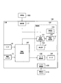
- FIG. 1 is a diagram showing a configuration of a tool management system 1 according to an embodiment.
- the tool management system 1 has a tool 100 and a management server 300.
- the management server 300 is an example of a server device.
- the tool 100 is a binding machine (for example, a reinforcing bar binding machine) which is a kind of electric tool.
- the tool 100 may be an electric tool other than the binding machine, for example, an electric drill, an electric screwdriver, an electric saw, a grinder, a grinder, or the like.
- the tool 100 may be a tool such as a manual tool that uses pneumatic pressure as power (for example, a pneumatic tool) or a tool that uses hydraulic pressure as power (for example, a hydraulic tool).
- the tool 100 is a cordless type electric tool, and is driven by electric power supplied from a driving battery 110 (battery pack).
- the drive battery 110 is configured to be removable from the tool 100.
- the drive battery 110 may be a secondary battery, for example, a lithium ion battery.
- the drive battery 110 is charged by a charger (not shown) in a state where it is removed from the tool 100.
- the tool 100 has a binding portion 11, a main body portion 12, and a grip portion 13.
- the binding portion 11 has an arm that sandwiches the reinforcing bar, and binds the reinforcing bar by winding a wire supplied from the main body portion 12 around the reinforcing bar sandwiched between the arms.
- the main body 12 accommodates a reel around which a wire is wound.
- the wire is an example of a consumable that is consumed every time the tool 100 is used.
- the consumables may be consumables other than wires, such as nails or staplers.
- the main body 12 incorporates a motor 140 (see FIG. 2).
- the motor 140 supplies the wire to the binding portion 11 and generates a driving force for winding the wire around the reinforcing bar.
- the main body 12 is provided with a power switch 15 for turning on / off the power of the tool 100.
- the grip portion 13 is a member that extends downward from the main body portion 12 and is gripped by the tool user.
- a trigger 14 is provided at the upper end of the grip portion 13. When the trigger 14 is pushed down, the binding portion 11 and the main body portion 12 perform a binding operation.
- a trigger lock 16 that locks (fixes) the trigger 14 may be provided. When the trigger lock 16 is set to the locked state, the trigger 14 is locked so as not to be pushed down.
- a latch mechanism for attaching / detaching the drive battery 110 is provided at the lower end portion of the grip portion 13.
- the tool 100 has a communication function.
- the tool 100 has a wireless communication function using LPWA (Low Power Wide Area) technology.
- the tool 100 performs wireless communication with the base station 210 included in the communication network 200.
- the tool 100 communicates with the management server 300 via the communication network 200. For example, the tool 100 transmits the tool data and the positioning data to the management server 300. Further, the tool 100 transmits a tool identifier (tool ID) that identifies the tool 100 to the management server 300.
- tool ID tool identifier
- the tool data is data related to work using the tool 100, and includes, for example, at least one of operation count data, tool status data, and drive battery remaining amount data.
- the operation number data is data indicating the number of times the tool 100 has been operated (that is, the number of times the binding operation has been performed).
- the tool state data is data indicating the state of the tool 100, for example, an error state.
- the drive battery remaining amount data is data indicating the remaining amount of the drive battery 110. Battery level may be expressed as the ratio (percentage) of current level to capacity.
- the positioning data is data indicating the position of the tool 100, and is latitude / longitude data obtained by using GNSS (Global Navigation Satellite System) such as GPS (Global Positioning System).
- GNSS Global Navigation Satellite System
- GPS Global Positioning System
- the communication network 200 has a base station 210 that performs wireless communication with the tool 100.
- the communication network 200 includes at least one of a narrow area communication network (LAN: Local Area Network), a high area communication network (WAN: Wide Area Network), and the Internet.
- LAN Local Area Network
- WAN Wide Area Network
- the management server 300 is a device that manages the tool 100. Although FIG. 1 shows an example in which the management server 300 manages one tool 100, the management server 300 may manage a plurality of tools 100.
- the management server 300 is connected to the communication network 200.
- the management server 300 acquires data from the tool 100 via the communication network 200 and manages the acquired data.
- the management server 300 manages the progress of work based on the tool data and the positioning data acquired from the tool 100.
- the management server 300 may perform position grasping (tracking) of the tool 100 when the tool 100 is lost or stolen based on the positioning data acquired from the tool 100.
- the management server 300 manages the tool 100 lent to the user.
- FIG. 2 is a diagram showing a configuration of a tool 100 according to an embodiment.
- the tool 100 includes a battery connection unit 120, a motor drive unit 130, a motor 140, a communication unit 150, and a drive control unit 160. It has a reading unit 17.
- the battery connection unit 120 is a connector that is electrically connected to the drive battery 110.
- the motor drive unit 130 drives the motor 140 by converting the electric power supplied from the drive battery 110 and supplying the drive power to the motor 140.
- the drive control unit 160 controls the motor drive operation of the tool 100.
- the drive control unit 160 includes at least one processor and at least one memory. While the tool 100 is in use, the drive control unit 160 controls the drive of the motor 140.
- the drive control unit 160 drives the motor drive unit 130 so as to drive the motor 140 when the trigger 14 is pushed down in the power-on state of the tool 100 (that is, the state in which the power switch 15 is set to on). Control. As a result, the motor 140 is driven by the motor drive unit 130, and the binding unit 11 performs a binding operation.
- the drive control unit 160 manages operation number data indicating the number of times the bundling operation is performed, tool state data indicating the state of the tool 100, and battery remaining amount data (driving battery remaining amount data) of the drive battery 110. To do.
- the drive control unit 160 receives the latest operation count data, the latest tool status data, and the latest drive battery remaining amount data in response to an inquiry from the communication unit 150 (communication control unit 151). Output to unit 151).
- the drive control unit 160 may perform charge control for charging the communication battery 155 with the electric power supplied from the drive battery 110.
- the communication unit 150 communicates with the management server 300.
- the communication unit 150 includes a communication control unit 151, a wireless communication unit 152, a positioning unit 154, and a communication battery 170.
- the communication control unit 151 together with the drive control unit 160, constitutes a control unit that controls the tool 100.
- the communication control unit 151 controls the wireless communication unit 152 and the positioning unit 154.
- the communication control unit 151 includes at least one processor and at least one memory.
- the at least one processor and at least one memory constituting the communication control unit 151 may share a part or all of the at least one processor and at least one memory constituting the drive control unit 160.
- the communication control unit 151 makes an inquiry to the drive control unit 160, acquires operation count data, tool status data, and drive battery remaining amount data from the drive control unit 160, and acquires the data.
- the wireless communication unit 152 is controlled so as to transmit data. Further, the communication control unit 151 may manage the communication battery remaining amount data indicating the remaining amount of the communication battery 155, and may control the wireless communication unit 152 so as to transmit the communication battery remaining amount data.
- the communication control unit 151 controls the wireless communication unit 152 so as to transmit the positioning data acquired by the positioning unit 154.
- the transmission of the positioning data is performed not only while the tool 100 is in use but also in a state where the tool 100 is not used (for example, a power-off state).
- the wireless communication unit 152 performs wireless communication using LPWA technology under the control of the communication control unit 151.
- the wireless communication unit 152 converts the data input from the communication control unit 151 into a wireless signal, and transmits the wireless signal to the base station 210.
- the positioning unit 154 acquires positioning data indicating the geographical position of the tool 100 under the control of the communication control unit 151.
- the positioning unit 154 is configured to include a GNSS receiver.
- the GNSS receiver is, for example, a GPS receiver.
- the positioning unit 154 outputs the acquired positioning data to the communication control unit 151 under the control of the communication control unit 151.
- the positioning unit 154 may include GLONASS (Global Navigation Satellite System), IRNSS (Indian Regional Navigation Satellite System), COMPASS, Galileo, Quasi-Zenith Satellite System (Q), Quasi-Zenith Satellite System (Q), or Quasi-Zenith Satellite System (Q). It may be configured to include a machine. Further, the positioning unit 154 may be composed of a plurality of GNSS receivers.
- the communication battery 155 stores electric power for driving the communication unit 150.
- a secondary battery may be used, and for example, a lithium ion battery can be used.
- the reading unit 17 reads the identifier (consumables ID) of the consumables 500 attached to the tool 100 from the consumables 500, and outputs the read consumables ID to the communication unit 150 (communication control unit 151).
- the consumable item ID may be any ID as long as it can be read electrically or optically, and for example, a one-dimensional code (so-called bar code) or a two-dimensional code (for example, a QR code). (Registered trademark)), RF ID, etc.
- the communication control unit 151 may transmit the consumable ID to the management server 300 when a predetermined trigger occurs (for example, when the power of the tool 100 is turned on or when an inquiry is made from the management server 300), or the consumables ID is periodically consumed.
- the product ID may be transmitted to the management server 300.
- the communication control unit 151 may receive various instructions from the management server 300 via the wireless communication unit 152.
- the communication control unit 151 receives an instruction to stop the operation of the tool from the management server 300
- the communication control unit 151 outputs the received instruction to the drive control unit 160.
- the drive control unit 160 stops (locks) the operation of the tool 100 by stopping the supply of electric power to the motor drive unit 130 in response to an instruction input from the communication control unit 151.
- FIG. 3 is a diagram showing an example of the consumables accommodating portion 18 and the consumables 500 of the tool 100 according to the embodiment.
- the consumable item 500 has a reel 502 and a wire 501 wound around the reel 502.
- a label 503 on which the tool ID is printed is affixed to the reel 502.
- the tool ID may be a hashed ID.
- the consumables accommodating portion 18 of the tool 100 is provided with a shaft 18a that rotatably supports the hole 502a of the reel 502 and a reading unit 17 that optically reads the tool ID. After the consumables 500 are attached to the consumables accommodating unit 18, the reading unit 17 reads the tool ID printed on the label 503.
- FIG. 4 is a diagram showing a configuration of the management server 300 according to the embodiment.
- the management server 300 has a storage unit 310, a communication unit 320, and a control unit 330.
- the storage unit 310 stores various data used for control and processing by the control unit 330.
- the storage unit 310 includes an auxiliary storage device such as a hard disk and a flash memory.
- the storage unit 310 stores the tool database 311 and the genuine product database 312, the usage amount database 313, and the credit rating database 314.
- the tool database 311 is a database in which an identifier (user ID) of a user who is currently renting a tool having this tool ID is associated with each tool ID. When the rented tool is returned, the tool database 311 is updated so as to delete the user ID corresponding to the tool ID of this tool.
- the genuine product database 312 includes a genuine product list which is a list of genuine consumables IDs.
- the genuine product database 312 is a database in which the tool IDs of the tools to which the consumables having the consumables ID are attached are associated with each genuine consumables ID.
- the genuine consumables ID may be stored in a hashed state.
- the genuine product list may be a list of genuine consumables IDs shipped from the factory, or may be a list of genuine consumables IDs sold at stores and the like.
- the usage database 313 is a database in which the cumulative usage of consumables having this consumable ID is associated with each genuine consumable ID.
- the cumulative amount of consumables used may be determined by the number of times the consumables have been used, or by the usage time of the consumables.
- the number of times the consumable is used corresponds to the number of times the tool 100 is operated (for example, the number of shots).
- the usage time of consumables corresponds to the operating time of the tool 100.
- the credit rating database 314 is a database in which the credit rating based on the usage time or the number of times of use of the genuine product in the past is associated with each user ID.
- the credit rating may be a numerical value indicating the usage time or the number of times of use of the genuine product in the past, or may be a rank value calculated from such usage time or the number of times of use. The longer the genuine product has been used in the past, the higher the credit rating. In addition, the more times the genuine product has been used in the past, the higher the credit rating.
- the communication unit 320 communicates with the tool 100 via the communication network 200 under the control of the control unit 330.
- the communication unit 320 includes a communication interface for transmitting and receiving data by wired communication (or wireless communication).
- the communication unit 320 includes the tool ID of the tool 100, the consumable ID of the consumables attached to the tool 100, and the tool data of the tool 100 (operation count data, tool status data, drive battery). The remaining amount data) and the positioning data indicating the position of the tool 100 are received, and the received data is output to the control unit 330.
- the control unit 330 controls the communication unit 320 and the storage unit 310.
- the control unit 330 includes at least one processor and at least one memory.
- the processor reads a program from the memory constituting the main storage device and executes it.
- the control unit 330 includes the ID acquisition unit 331, the genuine product determination unit 332, the penalty processing unit 333, the usage amount management unit 334, the billing processing unit 335, and the ID forgery determination unit 336. , Consists of a credit rating unit 337.
- the ID acquisition unit 331 acquires the tool ID of the tool 100 and the consumable ID of the consumables attached to the tool 100 via the communication unit 320.
- the genuine product determination unit 332 is based on the genuine product list included in the genuine product database 312 stored in the storage unit 310 and the consumable product ID acquired by the ID acquisition unit 331, and the target consumption indicated by this consumable product ID. Determine if the product is genuine. Specifically, the genuine product determination unit 332 determines that the target consumable product is a genuine product when the consumable product ID acquired by the ID acquisition unit 331 is included in the genuine product list. When the genuine product determination unit 332 determines that the target consumable product is a genuine product, the genuine product determination unit 332 stores the consumable product ID of the target consumable product and the tool ID of the tool 100 to which the target consumable product is attached in association with each other. Store in 310 (genuine product database 312). This makes it easier to understand which genuine product is attached to which tool.
- the genuine product determination unit 332 determines that the target consumables are non-genuine products (so-called pirated consumables). To do.
- the penalty processing unit 333 may perform a process of transmitting an instruction to stop the operation of the tool 100 to which the non-genuine product is attached to the tool 100. .. Specifically, the penalty processing unit 333 controls the communication unit 320 so as to transmit a lock instruction to the tool 100 to which the non-genuine product is attached. Further, the penalty processing unit 333 may perform a process of imposing a penalty on the user of the tool 100 to which the non-genuine product is attached, based on the tool database 311321 stored in the storage unit 310. The penalty may be a fine to this user or prohibit subsequent lending of tools to this user. This makes it easier to prevent the use of non-genuine products.
- the penalty processing unit 333 may store the position where the non-genuine product is used in the storage unit 310 based on the positioning data received from the tool 100. .. For example, when the penalty processing unit 333 simultaneously receives the consumable ID and the positioning data from the tool 100, the penalty processing unit 333 stores the position specified based on the positioning data received at the same time as the consumable ID as the position where the non-genuine product is used. It may be stored in the unit 310.
- the penalty processing unit 333 stores the position specified based on the positioning data received from the tool 100 at a timing close to the timing when the consumable ID is received from the tool 100 as the position where the non-genuine product is used. You may remember. Further, the penalty processing unit 333 may store the position where the non-genuine product is used and at least one of the tool ID and the consumable product ID in the storage unit 310 in association with each other.
- the position where the non-genuine product is used is set in response to a request from a management terminal (for example, a smartphone, a personal computer, etc.). It may be transmitted to the management terminal via the communication unit 320. This makes it easier for the user of the management terminal to know where the non-genuine product was used. Further, the management server 300 may associate the position where the non-genuine product is used with at least one of the tool ID and the consumable product ID and transmit it to the management terminal via the communication unit 320. This makes it easy for the user of the management terminal to know where, what kind of tool, and / and what kind of consumable, the non-genuine product was used.
- a management terminal for example, a smartphone, a personal computer, etc.
- the management server 300 may associate the position where the non-genuine product is used with at least one of the tool ID and the consumable product ID and transmit it to the management terminal via the communication unit 320. This makes it easy for the user of the management terminal to know where, what kind of
- the management terminal that has received the position where the non-genuine product is used may display an image showing the position where the non-genuine product is used on the display unit of the management terminal.
- the management terminal displays a map on the display unit, and displays an image (for example, an arrow mark) indicating the position where the non-genuine product is used on the map, which corresponds to the position where the non-genuine product is used. It may be displayed in. Further, the management terminal may display an image showing at least one of the tool ID and the consumable item ID on the display unit together with an image showing the position where the non-genuine product is used.
- the usage management unit 334 identifies the cumulative usage of the target consumable based on the tool data acquired via the communication unit 320, and the usage database. Manage 313.
- the usage amount management unit 334 may determine the number of operations included in the tool data as the cumulative usage amount, or the number of operations included in the tool data and the standard amount of consumables used by one operation of the tool 100. The cumulative usage may be specified from.
- the usage amount management unit 334 may determine the operating time of the tool 100 from the tool data, and specify the cumulative usage amount from the determined operating time and the standard consumables usage amount per unit time.
- the penalty processing unit 333 states that the user has refilled or refilled the consumables when the cumulative usage amount managed by the usage amount management unit 334 exceeds the threshold value indicating the upper limit usage amount of the genuine product. I reckon. In this case, the penalty processing unit 333 performs at least one of a process of transmitting an instruction to stop the operation of the tool 100 and a process of imposing a penalty on the user. This makes it easier to prevent fraudulent activities such as refilling consumables made by other companies by reusing the brackets of genuine consumables.
- the billing processing unit 335 uses the tool database 311 stored in the storage unit 310. Based on the quantity database 313, the user of the tool 100 may be charged according to the usage amount of the genuine product. For example, on the premise that the tool 100 is lent and the consumables are also lent, the pay-as-you-go charge can be performed according to the amount of the consumables used.
- the consumables ID acquired from a certain tool 100 (tool A) and the consumables ID acquired from another tool 100 (tool B) are both genuine consumables IDs.
- the penalty processing unit 333 performs at least one of a process of transmitting an instruction to stop the operation of one tool and a process of imposing a penalty on the user of the one tool.
- the ID counterfeit determination unit 336 determines that the consumables whose start has been started earlier are genuine products, and the consumables whose use has been started later are forged for the two consumables having the same consumable ID. It may be determined as a product.
- the ID forgery determination unit 336 may make a determination based on the user creditworthiness managed by the creditworthiness determination unit 337.
- the credit rating unit 337 manages the credit rating based on the usage time or the number of times of use of the genuine product in the past for each user.
- the penalty processing unit 333 is based on the tool database 311 and the credit rating database 314. To identify the user with the lower credit rating.
- the penalty processing unit 333 performs at least one of a process of transmitting an instruction to stop the operation of the tool 100 of the specified user and a process of imposing a penalty on the specified user.
- FIG. 5 is a diagram showing an operation example 1 of the management server 300 according to the embodiment.
- step S11 the ID acquisition unit 331 communicates between the communication unit 320 and the target tool to obtain the tool ID of the target tool and the consumable ID of the target consumable attached to the target tool. get.
- step S12 the genuine product determination unit 332 confirms whether or not the consumable product ID acquired in step S11 is included in the genuine product list.
- step S13 the genuine product determination unit 332 determines that the target consumables are non-genuine products.
- the penalty processing unit 333 performs at least one of a process of transmitting an instruction to stop the operation of the target tool and a process of imposing a penalty on the user of the target tool.
- step S14 the ID forgery determination unit 336 determines that the consumables ID acquired in step S11 is normal. It is confirmed whether or not it is associated with another tool ID in the product database 312.
- step S11 When the consumables ID acquired in step S11 is not associated with another tool ID in the genuine product database 312 (step S14: NO), in step S15, the genuine product determination unit 332 was acquired in step S11.
- the consumables ID and the tool ID are associated with each other and stored in the storage unit 310 (genuine product database 312).
- step S16 when the consumable item ID acquired in step S11 is associated with another tool ID in the genuine product database 312 (step S14: YES), in step S16, the ID forgery determination unit 336 is displayed in the tool database 311. Based on this, it corresponds to the user ID corresponding to the tool ID (hereinafter referred to as "tool ID # 1") acquired in step S11 and the other tool ID (hereinafter referred to as "tool ID # 2"). Check if the user ID is the same.
- step S15 the genuine product determination unit 332 stores the consumables ID and the tool ID acquired in step S11 in the storage unit 310 (genuine product database 312) in association with each other.
- step S17 the ID forgery determination unit 336 compares the user credit rating corresponding to the user ID # 1 with the user credit rating corresponding to the user ID # 2 based on the credit rating database 314. The ID forgery determination unit 336 determines that the user with the lower user credit rating has forged the genuine consumables ID.
- step S18 the penalty processing unit 333 performs at least one of a process of imposing a penalty on the user determined to have forged the consumable ID and a process of transmitting an instruction to stop the operation of the tool of this user.
- the tool ID corresponding to the user who is determined to have forged the consumables ID is the previously registered tool ID # 2
- the genuine database 312 is updated so as to delete the tool ID # 2.
- the consumables ID and the tool ID # 1 acquired in step S11 are associated with each other and stored in the genuine database 312.
- FIG. 6 is a diagram showing an operation example 2 of the management server 300 according to the embodiment.
- the usage amount management unit 334 manages the cumulative usage amount of genuine consumables by communicating with the communication unit 320 and the target tool.
- step S22 the usage management unit 334 compares the managed cumulative usage with the threshold value.
- step S23 the penalty processing unit 333 performs a process of transmitting an instruction to stop the operation of the target tool and a process of imposing a penalty on the user of the target tool. Do at least one or the other.
- step S24 the billing processing unit 335 performs a billing process according to the usage amount of the genuine consumables for the user of the target tool.
- the cumulative usage amount of the consumables 500 may be managed on the tool 100 side.
- the tool 100 may transmit the cumulative usage amount of the consumables 500 to the management server 300 by a predetermined trigger or periodically.
- the tool 100 may have a user authentication function. For example, the tool 100 determines whether or not the user of the tool 100 is a registered user by biometric authentication, and if it is determined that the user is a registered user, the user ID of this user is transmitted to the management server 300. You may send it. In this case, the management server 300 can identify the user of the tool 100 without using the tool database 311.
- the tool 100 may have a wired communication function in addition to or in place of the wireless communication function.
- a program that causes a computer to execute each process performed by the tool 100 or the management server 300 may be provided.
- the program may be recorded on a computer-readable medium.
- Computer-readable media can be used to install programs on a computer.
- the computer-readable medium on which the program is recorded may be a non-transient recording medium.
- the non-transient recording medium is not particularly limited, but may be, for example, a recording medium such as a CD-ROM or a DVD-ROM.
Abstract
This server device comprises: a communications unit that communicates with a tool; a storage unit that stores a list of identifiers of genuine products which are genuine consumables; and a control unit that acquires, from the tool, an identifier of a target consumable which is attached to the tool and determines whether the target consumable is the genuine product on the basis of the list and the identifier of the target consumable. Upon determining that the target consumable is the genuine product, the control unit manages the identifier of the target consumable in association with the identifier of the tool.
Description
本発明は、サーバ装置、工具、及び工具管理システムに関する。
The present invention relates to a server device, a tool, and a tool management system.
近年、結束機などの工具として、通信機能を有する工具が提案されている。例えば、工具は、工具の稼働データなどを他の装置に送信する。稼働データは、工具の異常判定に用いられる(例えば、特許文献1)。
In recent years, tools having a communication function have been proposed as tools such as binding machines. For example, a tool transmits tool operation data and the like to another device. The operation data is used for determining the abnormality of the tool (for example, Patent Document 1).
第1の態様に係るサーバ装置は、対象工具との通信を行う通信部と、正規の消耗品である正規品の識別子のリストを記憶する記憶部と、前記対象工具に取り付けられた対象消耗品の識別子を前記対象工具から取得し、前記リストと前記対象消耗品の識別子とに基づいて前記対象消耗品が前記正規品であるか否かを判定する制御部とを備える。前記制御部は、前記対象消耗品が前記正規品であると判定された場合、前記対象消耗品の識別子と前記対象工具の識別子とを対応付けて管理する。
The server device according to the first aspect includes a communication unit that communicates with the target tool, a storage unit that stores a list of identifiers of genuine products that are genuine consumables, and a target consumable that is attached to the target tool. It is provided with a control unit which obtains the identifier of the target tool from the target tool and determines whether or not the target consumable is a genuine product based on the list and the identifier of the target consumable. When it is determined that the target consumable item is a genuine product, the control unit manages the identifier of the target consumable item and the identifier of the target tool in association with each other.
第2の態様に係る工具は、サーバ装置との通信を行う通信部と、前記工具に取り付けられた対象消耗品の識別子を前記対象消耗品から読み取る読取部と、前記読み取られた対象消耗品の識別子を前記サーバ装置に送信するように前記通信部を制御する制御部とを備える。前記制御部は、前記対象消耗品の識別子の送信後、前記工具の動作を停止させる指示を前記サーバ装置から前記通信部が受信した場合、前記工具の動作を停止させる。
The tool according to the second aspect includes a communication unit that communicates with the server device, a reading unit that reads an identifier of the target consumable attached to the tool from the target consumable, and the read target consumable. It includes a control unit that controls the communication unit so as to transmit the identifier to the server device. After transmitting the identifier of the target consumable, the control unit stops the operation of the tool when the communication unit receives an instruction to stop the operation of the tool from the server device.
第3の態様に係る工具管理システムは、第1の態様に係る記載のサーバ装置と、第2の態様に係る記載の工具とを備える。
The tool management system according to the third aspect includes the server device according to the first aspect and the tool according to the second aspect.
図面を参照して、一実施形態に係る工具管理システムについて説明する。図面の記載において、同一又は類似の部分には同一又は類似の符号を付している。
The tool management system according to one embodiment will be described with reference to the drawings. In the description of the drawings, the same or similar parts are designated by the same or similar reference numerals.
(システム構成例)
図1は、一実施形態に係る工具管理システム1の構成を示す図である。 (System configuration example)
FIG. 1 is a diagram showing a configuration of atool management system 1 according to an embodiment.
図1は、一実施形態に係る工具管理システム1の構成を示す図である。 (System configuration example)
FIG. 1 is a diagram showing a configuration of a
図1に示すように、工具管理システム1は、工具100と、管理サーバ300とを有する。管理サーバ300は、サーバ装置の一例である。
As shown in FIG. 1, the tool management system 1 has a tool 100 and a management server 300. The management server 300 is an example of a server device.
一実施形態において、工具100は、電動工具の一種である結束機(例えば、鉄筋結束機)である。但し、工具100は、結束機以外の電動工具、例えば、電動ドリル、電動ドライバー、電動のこぎり、研削機、又は研磨機等であってもよい。工具100は、手動工具等、空圧を動力として用いる工具(例えば、空圧工具)、又は油圧を動力として用いる工具(例えば、油圧工具)であってもよい。
In one embodiment, the tool 100 is a binding machine (for example, a reinforcing bar binding machine) which is a kind of electric tool. However, the tool 100 may be an electric tool other than the binding machine, for example, an electric drill, an electric screwdriver, an electric saw, a grinder, a grinder, or the like. The tool 100 may be a tool such as a manual tool that uses pneumatic pressure as power (for example, a pneumatic tool) or a tool that uses hydraulic pressure as power (for example, a hydraulic tool).
例えば、工具100は、コードレス型の電動工具であり、駆動用バッテリ110(バッテリパック)から供給される電力によって駆動される。駆動用バッテリ110は、工具100に着脱可能に構成される。駆動用バッテリ110は二次電池であればよく、例えばリチウムイオンバッテリである。駆動用バッテリ110は、工具100から取り外された状態において、図示を省略する充電器により充電される。
For example, the tool 100 is a cordless type electric tool, and is driven by electric power supplied from a driving battery 110 (battery pack). The drive battery 110 is configured to be removable from the tool 100. The drive battery 110 may be a secondary battery, for example, a lithium ion battery. The drive battery 110 is charged by a charger (not shown) in a state where it is removed from the tool 100.
工具100は、結束部11と、本体部12と、グリップ部13とを有する。結束部11は、鉄筋を挟むアームを有し、アームに挟まれた鉄筋に対して本体部12から供給されるワイヤを巻き付けることにより、鉄筋の結束を行う。
The tool 100 has a binding portion 11, a main body portion 12, and a grip portion 13. The binding portion 11 has an arm that sandwiches the reinforcing bar, and binds the reinforcing bar by winding a wire supplied from the main body portion 12 around the reinforcing bar sandwiched between the arms.
本体部12は、ワイヤが巻き付けられたリールを収容する。ワイヤは、工具100の使用の度に消費される消耗品の一例である。但し、消耗品は、ワイヤ以外の消耗品、例えば釘又はステープラ等であってもよい。
The main body 12 accommodates a reel around which a wire is wound. The wire is an example of a consumable that is consumed every time the tool 100 is used. However, the consumables may be consumables other than wires, such as nails or staplers.
本体部12は、モータ140(図2参照)を内蔵する。モータ140は、ワイヤを結束部11に供給するとともにワイヤを鉄筋に巻き付けるための駆動力を発生させる。本体部12には、工具100の電源オン/オフを行うための電源スイッチ15が設けられる。
The main body 12 incorporates a motor 140 (see FIG. 2). The motor 140 supplies the wire to the binding portion 11 and generates a driving force for winding the wire around the reinforcing bar. The main body 12 is provided with a power switch 15 for turning on / off the power of the tool 100.
グリップ部13は、本体部12から下方に向けて延び、工具使用者によって把持される部材である。グリップ部13の上端部分には、トリガ14が設けられる。トリガ14が押し下げられることにより、結束部11及び本体部12が結束動作を行う。トリガ14をロック(固定)するトリガロック16が設けられてもよい。トリガロック16がロック状態に設定される場合、トリガ14が押し下げられないようにロックされる。グリップ部13の下端部分には、駆動用バッテリ110を着脱するためのラッチ機構が設けられる。
The grip portion 13 is a member that extends downward from the main body portion 12 and is gripped by the tool user. A trigger 14 is provided at the upper end of the grip portion 13. When the trigger 14 is pushed down, the binding portion 11 and the main body portion 12 perform a binding operation. A trigger lock 16 that locks (fixes) the trigger 14 may be provided. When the trigger lock 16 is set to the locked state, the trigger 14 is locked so as not to be pushed down. A latch mechanism for attaching / detaching the drive battery 110 is provided at the lower end portion of the grip portion 13.
工具100は、通信機能を有する。例えば、工具100は、LPWA(Low Power Wide Area)技術を用いた無線通信機能を有する。工具100は、通信ネットワーク200に含まれる基地局210との無線通信を行う。
The tool 100 has a communication function. For example, the tool 100 has a wireless communication function using LPWA (Low Power Wide Area) technology. The tool 100 performs wireless communication with the base station 210 included in the communication network 200.
工具100は、通信ネットワーク200を介して管理サーバ300との通信を行う。例えば、工具100は、工具データ及び測位データを管理サーバ300に送信する。また、工具100は、工具100を識別する工具識別子(工具ID)を管理サーバ300へ送信する。
The tool 100 communicates with the management server 300 via the communication network 200. For example, the tool 100 transmits the tool data and the positioning data to the management server 300. Further, the tool 100 transmits a tool identifier (tool ID) that identifies the tool 100 to the management server 300.
工具データは、工具100を使用する作業に関連するデータであって、例えば、作動回数データ、工具状態データ、及び駆動用バッテリ残量データのうち少なくとも1つを含む。作動回数データは、工具100が作動した回数(すなわち、結束動作を行った回数)を示すデータである。工具状態データは、工具100の状態、例えばエラー状態を示すデータである。駆動用バッテリ残量データは、駆動用バッテリ110の残量を示すデータである。バッテリ残量は、容量に対する現在の残量の割合(パーセンテージ)で示されてもよい。
The tool data is data related to work using the tool 100, and includes, for example, at least one of operation count data, tool status data, and drive battery remaining amount data. The operation number data is data indicating the number of times the tool 100 has been operated (that is, the number of times the binding operation has been performed). The tool state data is data indicating the state of the tool 100, for example, an error state. The drive battery remaining amount data is data indicating the remaining amount of the drive battery 110. Battery level may be expressed as the ratio (percentage) of current level to capacity.
測位データは、工具100の位置を示すデータであって、例えばGPS(Global Positioning System)等のGNSS(Global Navigation Satellite System)を用いて得られる緯度経度データである。
The positioning data is data indicating the position of the tool 100, and is latitude / longitude data obtained by using GNSS (Global Navigation Satellite System) such as GPS (Global Positioning System).
通信ネットワーク200は、工具100との無線通信を行う基地局210を有する。通信ネットワーク200は、狭域通信網(LAN:Local Area Network)、高域通信網(WAN:Wide Area Network)、及びインターネットのうち少なくとも1つを含む。
The communication network 200 has a base station 210 that performs wireless communication with the tool 100. The communication network 200 includes at least one of a narrow area communication network (LAN: Local Area Network), a high area communication network (WAN: Wide Area Network), and the Internet.
管理サーバ300は、工具100を管理する装置である。図1において、管理サーバ300が1つの工具100を管理する一例を示しているが、管理サーバ300は複数の工具100を管理していてもよい。
The management server 300 is a device that manages the tool 100. Although FIG. 1 shows an example in which the management server 300 manages one tool 100, the management server 300 may manage a plurality of tools 100.
管理サーバ300は、通信ネットワーク200に接続されている。管理サーバ300は、通信ネットワーク200を介して工具100からデータを取得し、取得したデータを管理する。
The management server 300 is connected to the communication network 200. The management server 300 acquires data from the tool 100 via the communication network 200 and manages the acquired data.
例えば、管理サーバ300は、工具100から取得した工具データ及び測位データに基づいて作業の進捗管理を行う。管理サーバ300は、工具100から取得した測位データに基づいて、工具100の紛失時又は盗難時等における工具100の位置把握(トラッキング)を行ってもよい。
For example, the management server 300 manages the progress of work based on the tool data and the positioning data acquired from the tool 100. The management server 300 may perform position grasping (tracking) of the tool 100 when the tool 100 is lost or stolen based on the positioning data acquired from the tool 100.
一実施形態において、工具100自体を安価に又は無料でユーザに貸与しつつ、純正の消耗品(正規品)の販売により利益を確保するビジネスモデルを想定する。管理サーバ300は、ユーザに貸与された工具100を管理する。
In one embodiment, assume a business model in which the tool 100 itself is lent to a user at low cost or free of charge, and profit is secured by selling genuine consumables (genuine products). The management server 300 manages the tool 100 lent to the user.
(工具の構成例)
図2は、一実施形態に係る工具100の構成を示す図である。 (Tool configuration example)
FIG. 2 is a diagram showing a configuration of atool 100 according to an embodiment.
図2は、一実施形態に係る工具100の構成を示す図である。 (Tool configuration example)
FIG. 2 is a diagram showing a configuration of a
図2に示すように、工具100は、上述したトリガ14及び電源スイッチ15に加えて、バッテリ接続部120と、モータ駆動部130と、モータ140と、通信部150と、駆動制御部160と、読取部17とを有する。
As shown in FIG. 2, in addition to the trigger 14 and the power switch 15 described above, the tool 100 includes a battery connection unit 120, a motor drive unit 130, a motor 140, a communication unit 150, and a drive control unit 160. It has a reading unit 17.
バッテリ接続部120は、駆動用バッテリ110と電気的に接続されるコネクタである。
The battery connection unit 120 is a connector that is electrically connected to the drive battery 110.
モータ駆動部130は、駆動制御部160の制御下で、駆動用バッテリ110から供給される電力を変換してモータ140に駆動電力を供給することにより、モータ140を駆動する。
Under the control of the drive control unit 160, the motor drive unit 130 drives the motor 140 by converting the electric power supplied from the drive battery 110 and supplying the drive power to the motor 140.
駆動制御部160は、工具100におけるモータ駆動動作を制御する。駆動制御部160は、少なくとも1つのプロセッサ及び少なくとも1つのメモリを含んで構成される。工具100の使用中において、駆動制御部160は、モータ140の駆動を制御する。駆動制御部160は、工具100の電源オン状態(すなわち、電源スイッチ15がオンに設定されている状態)において、トリガ14が押し下げられた際に、モータ140を駆動させるようにモータ駆動部130を制御する。その結果、モータ140がモータ駆動部130により駆動され、結束部11が結束動作を行う。
The drive control unit 160 controls the motor drive operation of the tool 100. The drive control unit 160 includes at least one processor and at least one memory. While the tool 100 is in use, the drive control unit 160 controls the drive of the motor 140. The drive control unit 160 drives the motor drive unit 130 so as to drive the motor 140 when the trigger 14 is pushed down in the power-on state of the tool 100 (that is, the state in which the power switch 15 is set to on). Control. As a result, the motor 140 is driven by the motor drive unit 130, and the binding unit 11 performs a binding operation.
駆動制御部160は、結束動作を行った回数を示す作動回数データと、工具100の状態を示す工具状態データと、駆動用バッテリ110のバッテリ残量データ(駆動用バッテリ残量データ)とを管理する。駆動制御部160は、通信部150(通信制御部151)からの問い合わせに応じて、最新の作動回数データ、最新の工具状態データ、及び最新の駆動用バッテリ残量データを通信部150(通信制御部151)に出力する。駆動制御部160は、駆動用バッテリ110から供給される電力によって通信用バッテリ155を充電する充電制御を行ってもよい。
The drive control unit 160 manages operation number data indicating the number of times the bundling operation is performed, tool state data indicating the state of the tool 100, and battery remaining amount data (driving battery remaining amount data) of the drive battery 110. To do. The drive control unit 160 receives the latest operation count data, the latest tool status data, and the latest drive battery remaining amount data in response to an inquiry from the communication unit 150 (communication control unit 151). Output to unit 151). The drive control unit 160 may perform charge control for charging the communication battery 155 with the electric power supplied from the drive battery 110.
通信部150は、管理サーバ300との通信を行う。通信部150は、通信制御部151と、無線通信部152と、測位部154と、通信用バッテリ170とを有する。通信制御部151は、駆動制御部160と共に、工具100における制御を行う制御部を構成する。
The communication unit 150 communicates with the management server 300. The communication unit 150 includes a communication control unit 151, a wireless communication unit 152, a positioning unit 154, and a communication battery 170. The communication control unit 151, together with the drive control unit 160, constitutes a control unit that controls the tool 100.
通信制御部151は、無線通信部152及び測位部154を制御する。通信制御部151は、少なくとも1つのプロセッサ及び少なくとも1つのメモリを含んで構成される。なお、通信制御部151を構成する少なくとも1つのプロセッサ及び少なくとも1つのメモリは、駆動制御部160を構成する少なくとも1つのプロセッサ及び少なくとも1つのメモリの一部又は全部を共有してもよい。
The communication control unit 151 controls the wireless communication unit 152 and the positioning unit 154. The communication control unit 151 includes at least one processor and at least one memory. The at least one processor and at least one memory constituting the communication control unit 151 may share a part or all of the at least one processor and at least one memory constituting the drive control unit 160.
工具100の使用中において、通信制御部151は、駆動制御部160に対して問い合わせを行い、作動回数データ、工具状態データ、及び駆動用バッテリ残量データを駆動制御部160から取得し、取得したデータを送信するように無線通信部152を制御する。また、通信制御部151は、通信用バッテリ155の残量を示す通信用バッテリ残量データを管理し、通信用バッテリ残量データを送信するよう無線通信部152を制御してもよい。
While the tool 100 is in use, the communication control unit 151 makes an inquiry to the drive control unit 160, acquires operation count data, tool status data, and drive battery remaining amount data from the drive control unit 160, and acquires the data. The wireless communication unit 152 is controlled so as to transmit data. Further, the communication control unit 151 may manage the communication battery remaining amount data indicating the remaining amount of the communication battery 155, and may control the wireless communication unit 152 so as to transmit the communication battery remaining amount data.
通信制御部151は、測位部154により取得される測位データを送信するよう無線通信部152を制御する。測位データの送信は、工具100の使用中に限らず、工具100が使用されていない状態(例えば、電源オフ状態)においても行われる。
The communication control unit 151 controls the wireless communication unit 152 so as to transmit the positioning data acquired by the positioning unit 154. The transmission of the positioning data is performed not only while the tool 100 is in use but also in a state where the tool 100 is not used (for example, a power-off state).
無線通信部152は、通信制御部151の制御下で、LPWA技術を用いた無線通信を行う。無線通信部152は、通信制御部151から入力されるデータを無線信号に変換し、無線信号を基地局210に送信する。
The wireless communication unit 152 performs wireless communication using LPWA technology under the control of the communication control unit 151. The wireless communication unit 152 converts the data input from the communication control unit 151 into a wireless signal, and transmits the wireless signal to the base station 210.
測位部154は、通信制御部151の制御下で、工具100の地理的な位置を示す測位データを取得する。測位部154は、GNSS受信機を含んで構成される。GNSS受信機は、例えばGPS受信機である。測位部154は、通信制御部151の制御下で、取得した測位データを通信制御部151に出力する。測位部154は、例えば、GNSS受信機として、GLONASS(Global Navigation Satellite System)、IRNSS(Indian Regional Navigational Satellite System)、COMPASS、Galileo、或いは準天頂衛星システム(QZSS:Quasi-Zenith Satellites System)等の受信機を含んで構成されてよい。また測位部154は、複数のGNSS受信機により構成されてもよい。
The positioning unit 154 acquires positioning data indicating the geographical position of the tool 100 under the control of the communication control unit 151. The positioning unit 154 is configured to include a GNSS receiver. The GNSS receiver is, for example, a GPS receiver. The positioning unit 154 outputs the acquired positioning data to the communication control unit 151 under the control of the communication control unit 151. As a GNSS receiver, the positioning unit 154 may include GLONASS (Global Navigation Satellite System), IRNSS (Indian Regional Navigation Satellite System), COMPASS, Galileo, Quasi-Zenith Satellite System (Q), Quasi-Zenith Satellite System (Q), or Quasi-Zenith Satellite System (Q). It may be configured to include a machine. Further, the positioning unit 154 may be composed of a plurality of GNSS receivers.
通信用バッテリ155は、通信部150を駆動するための電力を蓄える。通信用バッテリ155としては二次電池を用いればよく、例えばリチウムイオンバッテリを用いることができる。
The communication battery 155 stores electric power for driving the communication unit 150. As the communication battery 155, a secondary battery may be used, and for example, a lithium ion battery can be used.
読取部17は、工具100に取り付けられた消耗品500の識別子(消耗品ID)をこの消耗品500から読み取り、読み取った消耗品IDを通信部150(通信制御部151)に出力する。消耗品IDは、電気的に又は光学的に読み取り可能なIDであればどのようなIDであってもよいが、例えば、一次元コード(いわゆる、バーコード)、二次元コード(例えば、QRコード(登録商標))、RF ID等である。通信制御部151は、所定のトリガの発生時(例えば、工具100の電源オン時又は管理サーバ300からの問い合わせ時)に消耗品IDを管理サーバ300に送信してもよいし、周期的に消耗品IDを管理サーバ300に送信してもよい。
The reading unit 17 reads the identifier (consumables ID) of the consumables 500 attached to the tool 100 from the consumables 500, and outputs the read consumables ID to the communication unit 150 (communication control unit 151). The consumable item ID may be any ID as long as it can be read electrically or optically, and for example, a one-dimensional code (so-called bar code) or a two-dimensional code (for example, a QR code). (Registered trademark)), RF ID, etc. The communication control unit 151 may transmit the consumable ID to the management server 300 when a predetermined trigger occurs (for example, when the power of the tool 100 is turned on or when an inquiry is made from the management server 300), or the consumables ID is periodically consumed. The product ID may be transmitted to the management server 300.
通信制御部151は、無線通信部152を介して、管理サーバ300から各種の指示を受信してもよい。通信制御部151は、工具の動作を停止させる指示を管理サーバ300から受信した場合、受信した指示を駆動制御部160に出力する。駆動制御部160は、通信制御部151から入力された指示に応じて、モータ駆動部130への電力の供給を停止することにより工具100の動作を停止(ロック)させる。
The communication control unit 151 may receive various instructions from the management server 300 via the wireless communication unit 152. When the communication control unit 151 receives an instruction to stop the operation of the tool from the management server 300, the communication control unit 151 outputs the received instruction to the drive control unit 160. The drive control unit 160 stops (locks) the operation of the tool 100 by stopping the supply of electric power to the motor drive unit 130 in response to an instruction input from the communication control unit 151.
図3は、一実施形態に係る工具100の消耗品収容部18及び消耗品500の一例を示す図である。
FIG. 3 is a diagram showing an example of the consumables accommodating portion 18 and the consumables 500 of the tool 100 according to the embodiment.
図3に示すように、消耗品500は、リール502と、リール502に巻き付けられたワイヤ501とを有する。リール502には、工具IDが印刷されたラベル503が貼付けられている。工具IDは、ハッシュ化されたIDであってもよい。
As shown in FIG. 3, the consumable item 500 has a reel 502 and a wire 501 wound around the reel 502. A label 503 on which the tool ID is printed is affixed to the reel 502. The tool ID may be a hashed ID.
工具100の消耗品収容部18は、リール502の孔502aを回転可能に支持する軸18aと、工具IDを光学的に読み取る読取部17とが設けられる。消耗品500が消耗品収容部18に取り付けられた後、ラベル503に印刷された工具IDを読取部17が読み取る。
The consumables accommodating portion 18 of the tool 100 is provided with a shaft 18a that rotatably supports the hole 502a of the reel 502 and a reading unit 17 that optically reads the tool ID. After the consumables 500 are attached to the consumables accommodating unit 18, the reading unit 17 reads the tool ID printed on the label 503.
(管理サーバの構成例)
図4は、一実施形態に係る管理サーバ300の構成を示す図である。 (Management server configuration example)
FIG. 4 is a diagram showing a configuration of themanagement server 300 according to the embodiment.
図4は、一実施形態に係る管理サーバ300の構成を示す図である。 (Management server configuration example)
FIG. 4 is a diagram showing a configuration of the
図4に示すように、管理サーバ300は、記憶部310と、通信部320と、制御部330とを有する。
As shown in FIG. 4, the management server 300 has a storage unit 310, a communication unit 320, and a control unit 330.
記憶部310は、制御部330による制御及び処理に用いられる各種のデータを記憶する。記憶部310は、ハードディスクやフラッシュメモリ等の補助記憶装置を含んで構成される。
The storage unit 310 stores various data used for control and processing by the control unit 330. The storage unit 310 includes an auxiliary storage device such as a hard disk and a flash memory.
例えば、記憶部310は、工具データベース311と、正規品データベース312と、使用量データベース313と、信用度データベース314とを記憶する。
For example, the storage unit 310 stores the tool database 311 and the genuine product database 312, the usage amount database 313, and the credit rating database 314.
工具データベース311は、工具IDごとに、この工具IDを有する工具が現在貸与されているユーザの識別子(ユーザID)が対応付けられたデータベースである。貸与された工具が返却された場合、この工具の工具IDに対応するユーザIDを削除するように工具データベース311が更新される。
The tool database 311 is a database in which an identifier (user ID) of a user who is currently renting a tool having this tool ID is associated with each tool ID. When the rented tool is returned, the tool database 311 is updated so as to delete the user ID corresponding to the tool ID of this tool.
正規品データベース312は、正規品の消耗品IDのリストである正規品リストを含む。正規品データベース312は、正規品の消耗品IDごとに、この消耗品IDを有する消耗品が取り付けられている工具の工具IDが対応付けられたデータベースである。正規品の消耗品IDは、ハッシュ化された状態で記憶されていてもよい。正規品リストは、工場から出荷された正規品の消耗品IDのリストであってもよいし、店舗等において販売された正規品の消耗品IDのリストであってもよい。
The genuine product database 312 includes a genuine product list which is a list of genuine consumables IDs. The genuine product database 312 is a database in which the tool IDs of the tools to which the consumables having the consumables ID are attached are associated with each genuine consumables ID. The genuine consumables ID may be stored in a hashed state. The genuine product list may be a list of genuine consumables IDs shipped from the factory, or may be a list of genuine consumables IDs sold at stores and the like.
使用量データベース313は、正規品の消耗品IDごとに、この消耗品IDを有する消耗品の累積使用量が対応付けられたデータベースである。消耗品の累積使用量は、消耗品の使用回数により定められてもよいし、消耗品の使用時間により定められてもよい。消耗品の使用回数は、工具100の作動回数(例えば、ショット回数)に相当する。消耗品の使用時間は、工具100の作動時間に相当する。
The usage database 313 is a database in which the cumulative usage of consumables having this consumable ID is associated with each genuine consumable ID. The cumulative amount of consumables used may be determined by the number of times the consumables have been used, or by the usage time of the consumables. The number of times the consumable is used corresponds to the number of times the tool 100 is operated (for example, the number of shots). The usage time of consumables corresponds to the operating time of the tool 100.
信用度データベース314は、ユーザIDごとに、過去における正規品の使用時間又は使用回数に基づく信用度が対応付けられたデータベースである。信用度は、過去における正規品の使用時間又は使用回数を示す数値であってもよいし、このような使用時間又は使用回数から算出されるランク値であってもよい。過去における正規品の使用時間が長い程、信用度が高くなる。また、過去における正規品の使用回数が多い程、信用度が高くなる。
The credit rating database 314 is a database in which the credit rating based on the usage time or the number of times of use of the genuine product in the past is associated with each user ID. The credit rating may be a numerical value indicating the usage time or the number of times of use of the genuine product in the past, or may be a rank value calculated from such usage time or the number of times of use. The longer the genuine product has been used in the past, the higher the credit rating. In addition, the more times the genuine product has been used in the past, the higher the credit rating.
通信部320は、制御部330の制御下で、通信ネットワーク200を介して工具100との通信を行う。通信部320は、有線通信(又は無線通信)によりデータを送受信する通信インターフェイスを含む。
The communication unit 320 communicates with the tool 100 via the communication network 200 under the control of the control unit 330. The communication unit 320 includes a communication interface for transmitting and receiving data by wired communication (or wireless communication).
通信部320は、工具100から、この工具100の工具IDと、この工具100に取り付けられた消耗品の消耗品IDと、この工具100の工具データ(作動回数データ、工具状態データ、駆動用バッテリ残量データ)と、この工具100の位置を示す測位データとを受信し、受信したデータを制御部330に出力する。
From the tool 100, the communication unit 320 includes the tool ID of the tool 100, the consumable ID of the consumables attached to the tool 100, and the tool data of the tool 100 (operation count data, tool status data, drive battery). The remaining amount data) and the positioning data indicating the position of the tool 100 are received, and the received data is output to the control unit 330.
制御部330は、通信部320及び記憶部310を制御する。制御部330は、少なくとも1つのプロセッサ及び少なくとも1つのメモリを含んで構成される。プロセッサは、主記憶装置を構成するメモリからプログラムを読み出して実行する。
The control unit 330 controls the communication unit 320 and the storage unit 310. The control unit 330 includes at least one processor and at least one memory. The processor reads a program from the memory constituting the main storage device and executes it.
制御部330は、プログラムを実行することにより、ID取得部331と、正規品判定部332と、ペナルティ処理部333と、使用量管理部334と、課金処理部335と、ID偽造判定部336と、信用度判定部337とを構成する。
By executing the program, the control unit 330 includes the ID acquisition unit 331, the genuine product determination unit 332, the penalty processing unit 333, the usage amount management unit 334, the billing processing unit 335, and the ID forgery determination unit 336. , Consists of a credit rating unit 337.
ID取得部331は、通信部320を介して、工具100の工具IDと、この工具100に取り付けられた消耗品の消耗品IDとを取得する。
The ID acquisition unit 331 acquires the tool ID of the tool 100 and the consumable ID of the consumables attached to the tool 100 via the communication unit 320.
正規品判定部332は、記憶部310に記憶された正規品データベース312に含まれる正規品リストと、ID取得部331により取得された消耗品IDとに基づいて、この消耗品IDが示す対象消耗品が正規品であるか否かを判定する。具体的には、正規品判定部332は、ID取得部331により取得された消耗品IDが正規品リストに含まれている場合、対象消耗品が正規品であると判定する。正規品判定部332は、対象消耗品が正規品であると判定した場合、この対象消耗品の消耗品IDと、この対象消耗品が取り付けられた工具100の工具IDとを対応付けて記憶部310(正規品データベース312)に記憶させる。これにより、どの正規品がどの工具に取り付けられているかを把握しやすくなる。
The genuine product determination unit 332 is based on the genuine product list included in the genuine product database 312 stored in the storage unit 310 and the consumable product ID acquired by the ID acquisition unit 331, and the target consumption indicated by this consumable product ID. Determine if the product is genuine. Specifically, the genuine product determination unit 332 determines that the target consumable product is a genuine product when the consumable product ID acquired by the ID acquisition unit 331 is included in the genuine product list. When the genuine product determination unit 332 determines that the target consumable product is a genuine product, the genuine product determination unit 332 stores the consumable product ID of the target consumable product and the tool ID of the tool 100 to which the target consumable product is attached in association with each other. Store in 310 (genuine product database 312). This makes it easier to understand which genuine product is attached to which tool.
一方、ID取得部331により取得された消耗品IDが正規品リストに含まれていない場合、正規品判定部332は、対象消耗品が非正規品(いわゆる、海賊版の消耗品)であると判定する。
On the other hand, when the consumables ID acquired by the ID acquisition unit 331 is not included in the genuine product list, the genuine product determination unit 332 determines that the target consumables are non-genuine products (so-called pirated consumables). To do.
対象消耗品が非正規品であると判定された場合、ペナルティ処理部333は、この非正規品が取り付けられた工具100の動作を停止させる指示をこの工具100に送信する処理を行ってもよい。具体的には、ペナルティ処理部333は、非正規品が取り付けられた工具100に対してロック指示を送信するように通信部320を制御する。また、ペナルティ処理部333は、記憶部310に記憶された工具データベース311321に基づいて、この非正規品が取り付けられた工具100のユーザにペナルティを課す処理を行ってもよい。ペナルティは、このユーザに対する罰金であってもよいし、このユーザに対するその後の工具貸与を禁止することであってもよい。これにより、非正規品の使用を抑止しやすくなる。
When it is determined that the target consumable is a non-genuine product, the penalty processing unit 333 may perform a process of transmitting an instruction to stop the operation of the tool 100 to which the non-genuine product is attached to the tool 100. .. Specifically, the penalty processing unit 333 controls the communication unit 320 so as to transmit a lock instruction to the tool 100 to which the non-genuine product is attached. Further, the penalty processing unit 333 may perform a process of imposing a penalty on the user of the tool 100 to which the non-genuine product is attached, based on the tool database 311321 stored in the storage unit 310. The penalty may be a fine to this user or prohibit subsequent lending of tools to this user. This makes it easier to prevent the use of non-genuine products.
また、ペナルティ処理部333は、対象消耗品が非正規品であると判定する場合、工具100から受信した測位データに基づいて、非正規品が使用された位置を記憶部310に記憶してよい。例えば、ペナルティ処理部333は、工具100から消耗品IDと測位データを同時に受信した場合、消耗品IDと同時に受信した測位データに基づき特定される位置を非正規品が使用された位置として、記憶部310に記憶してよい。例えば、ペナルティ処理部333は、工具100から消耗品IDを受信したタイミングに近いタイミングで工具100から受信した測位データに基づき特定される位置を非正規品が使用された位置として、記憶部310に記憶してよい。また、ペナルティ処理部333は、非正規品が使用された位置と、工具ID及び消耗品IDの少なくとも一つと、を関連付けて、記憶部310に記憶してよい。
Further, when the penalty processing unit 333 determines that the target consumable product is a non-genuine product, the penalty processing unit 333 may store the position where the non-genuine product is used in the storage unit 310 based on the positioning data received from the tool 100. .. For example, when the penalty processing unit 333 simultaneously receives the consumable ID and the positioning data from the tool 100, the penalty processing unit 333 stores the position specified based on the positioning data received at the same time as the consumable ID as the position where the non-genuine product is used. It may be stored in the unit 310. For example, the penalty processing unit 333 stores the position specified based on the positioning data received from the tool 100 at a timing close to the timing when the consumable ID is received from the tool 100 as the position where the non-genuine product is used. You may remember. Further, the penalty processing unit 333 may store the position where the non-genuine product is used and at least one of the tool ID and the consumable product ID in the storage unit 310 in association with each other.
また、管理サーバ300は、非正規品が使用された位置を記憶する場合、例えば、管理端末(例えば、スマートフォン、パーソナルコンピュータ等)からの要求に応じて、非正規品が使用された位置を、管理端末に通信部320を介して送信してよい。これにより、管理端末のユーザは、何処で非正規品が使用されたか知ることが容易になる。また、管理サーバ300は、非正規品が使用された位置を、工具ID及び消耗品IDの少なくとも一つと関連付けて、管理端末に通信部320を介して送信してよい。これにより、管理端末のユーザは、何処で、どのような工具、又は/及び、どのような消耗品において、非正規品が使用されたか知ることが容易になる。
Further, when the management server 300 stores the position where the non-genuine product is used, for example, the position where the non-genuine product is used is set in response to a request from a management terminal (for example, a smartphone, a personal computer, etc.). It may be transmitted to the management terminal via the communication unit 320. This makes it easier for the user of the management terminal to know where the non-genuine product was used. Further, the management server 300 may associate the position where the non-genuine product is used with at least one of the tool ID and the consumable product ID and transmit it to the management terminal via the communication unit 320. This makes it easy for the user of the management terminal to know where, what kind of tool, and / and what kind of consumable, the non-genuine product was used.
ここで非正規品が使用された位置を受信した管理端末は、非正規品が使用された位置を示す画像を当該管理端末の表示部に表示してよい。例えば、管理端末は、表示部に地図を表示し、地図上において、非正規品が使用された位置を示す画像(例えば、矢印マーク等)を、非正規品が使用された位置に対応する部分に表示してもよい。また管理端末は、非正規品が使用された位置を示す画像とともに、工具ID及び消耗品IDの少なくとも一つを示す画像を、表示部に表示してよい。
Here, the management terminal that has received the position where the non-genuine product is used may display an image showing the position where the non-genuine product is used on the display unit of the management terminal. For example, the management terminal displays a map on the display unit, and displays an image (for example, an arrow mark) indicating the position where the non-genuine product is used on the map, which corresponds to the position where the non-genuine product is used. It may be displayed in. Further, the management terminal may display an image showing at least one of the tool ID and the consumable item ID on the display unit together with an image showing the position where the non-genuine product is used.
対象消耗品が正規品であると判定された場合、使用量管理部334は、通信部320を介して取得される工具データに基づいてこの対象消耗品の累積使用量を特定し、使用量データベース313を管理する。使用量管理部334は、工具データに含まれる作動回数を累積使用量として判定してもよいし、工具データに含まれる作動回数と工具100の1回の作動による標準的な消耗品使用量とから累積使用量を特定してもよい。使用量管理部334は、工具データから工具100の作動時間を判定し、判定した作動時間と単位時間あたりの標準的な消耗品使用量とから累積使用量を特定してもよい。
When it is determined that the target consumable is a genuine product, the usage management unit 334 identifies the cumulative usage of the target consumable based on the tool data acquired via the communication unit 320, and the usage database. Manage 313. The usage amount management unit 334 may determine the number of operations included in the tool data as the cumulative usage amount, or the number of operations included in the tool data and the standard amount of consumables used by one operation of the tool 100. The cumulative usage may be specified from. The usage amount management unit 334 may determine the operating time of the tool 100 from the tool data, and specify the cumulative usage amount from the determined operating time and the standard consumables usage amount per unit time.
ペナルティ処理部333は、使用量管理部334が管理している累積使用量が、正規品の上限の使用量を示す閾値を超えた場合、ユーザが消耗品の詰め替え又は補充(リフィル)を行ったとみなす。この場合、ペナルティ処理部333は、工具100の動作を停止させる指示を送信する処理、及びユーザにペナルティを課す処理の少なくともいずれか一方を行う。これにより、正規品である消耗品のブラケットを再利用して他社製の消耗品をリフィルするような不正行為を抑止しやすくなる。
The penalty processing unit 333 states that the user has refilled or refilled the consumables when the cumulative usage amount managed by the usage amount management unit 334 exceeds the threshold value indicating the upper limit usage amount of the genuine product. I reckon. In this case, the penalty processing unit 333 performs at least one of a process of transmitting an instruction to stop the operation of the tool 100 and a process of imposing a penalty on the user. This makes it easier to prevent fraudulent activities such as refilling consumables made by other companies by reusing the brackets of genuine consumables.
使用量管理部334が管理している正規品の使用量が、正規品の上限の使用量を示す閾値以下である場合、課金処理部335は、記憶部310に記憶された工具データベース311及び使用量データベース313に基づいて、正規品の使用量に応じた課金処理を工具100のユーザについて行ってもよい。例えば工具100を貸与するとともに消耗品も貸与するような前提下において、この消耗品の使用量に応じた従量課金を行うことができる。
When the usage amount of the genuine product managed by the usage amount management unit 334 is equal to or less than the threshold value indicating the upper limit usage amount of the genuine product, the billing processing unit 335 uses the tool database 311 stored in the storage unit 310. Based on the quantity database 313, the user of the tool 100 may be charged according to the usage amount of the genuine product. For example, on the premise that the tool 100 is lent and the consumables are also lent, the pay-as-you-go charge can be performed according to the amount of the consumables used.
ID偽造判定部336は、ある工具100(工具A)から取得された消耗品IDと、他の工具100(工具B)から取得された消耗品IDとがいずれも正規品の消耗品IDである場合であって、かつ、工具Aから取得した消耗品IDと工具Bから取得した消耗品IDとが同一である場合、一方の工具からの消耗品IDが偽造されたものであるとみなす。この場合、ペナルティ処理部333は、一方の工具の動作を停止させる指示を送信する処理、及び一方の工具のユーザにペナルティを課す処理の少なくともいずれか一方を行う。これにより、例えば正規品である消耗品から消耗品IDを複写して偽造品に貼り付けたり、使用済みの正規品から剥がされた消耗品IDを偽造品に貼り付けたりするような不正行為を抑止しやすくなる。ここで、ID偽造判定部336は、同一の消耗品IDを有する2つの消耗品について、先に開始が開始された消耗品を正規品と判定し、後から使用が開始された消耗品を偽造品と判定してもよい。
In the ID forgery determination unit 336, the consumables ID acquired from a certain tool 100 (tool A) and the consumables ID acquired from another tool 100 (tool B) are both genuine consumables IDs. In this case, and if the consumables ID obtained from the tool A and the consumables ID obtained from the tool B are the same, it is considered that the consumables ID from one of the tools is forged. In this case, the penalty processing unit 333 performs at least one of a process of transmitting an instruction to stop the operation of one tool and a process of imposing a penalty on the user of the one tool. As a result, for example, fraudulent acts such as copying the consumables ID from the genuine consumables and pasting them on the counterfeit, or pasting the consumables ID peeled off from the used genuines on the counterfeits. It becomes easier to deter. Here, the ID counterfeit determination unit 336 determines that the consumables whose start has been started earlier are genuine products, and the consumables whose use has been started later are forged for the two consumables having the same consumable ID. It may be determined as a product.
或いは、ID偽造判定部336は、信用度判定部337が管理するユーザ信用度に基づく判定を行ってもよい。信用度判定部337は、過去における正規品の使用時間又は使用回数に基づく信用度をユーザごとに管理する。ペナルティ処理部333は、工具Aから取得した消耗品IDと工具Bから取得した消耗品IDとが同一であって且つ正規品の消耗品IDである場合、工具データベース311と信用度データベース314とに基づいて、信用度が低い方のユーザを特定する。ペナルティ処理部333は、特定したユーザの工具100の動作を停止させる指示を送信する処理、及び特定したユーザにペナルティを課す処理の少なくともいずれか一方を行う。
Alternatively, the ID forgery determination unit 336 may make a determination based on the user creditworthiness managed by the creditworthiness determination unit 337. The credit rating unit 337 manages the credit rating based on the usage time or the number of times of use of the genuine product in the past for each user. When the consumable ID acquired from the tool A and the consumable ID acquired from the tool B are the same and are genuine consumable IDs, the penalty processing unit 333 is based on the tool database 311 and the credit rating database 314. To identify the user with the lower credit rating. The penalty processing unit 333 performs at least one of a process of transmitting an instruction to stop the operation of the tool 100 of the specified user and a process of imposing a penalty on the specified user.
(管理サーバの動作例)
図5は、一実施形態に係る管理サーバ300の動作例1を示す図である。 (Operation example of management server)
FIG. 5 is a diagram showing an operation example 1 of themanagement server 300 according to the embodiment.
図5は、一実施形態に係る管理サーバ300の動作例1を示す図である。 (Operation example of management server)
FIG. 5 is a diagram showing an operation example 1 of the
図5に示すように、ステップS11において、ID取得部331は、通信部320と対象工具との通信により、対象工具の工具IDと、対象工具に取り付けられた対象消耗品の消耗品IDとを取得する。
As shown in FIG. 5, in step S11, the ID acquisition unit 331 communicates between the communication unit 320 and the target tool to obtain the tool ID of the target tool and the consumable ID of the target consumable attached to the target tool. get.
ステップS12において、正規品判定部332は、ステップS11で取得された消耗品IDが正規品リストに含まれているか否かを確認する。
In step S12, the genuine product determination unit 332 confirms whether or not the consumable product ID acquired in step S11 is included in the genuine product list.
ステップS11で取得された消耗品IDが正規品リストに含まれていない場合(ステップS12:NO)、ステップS13において、正規品判定部332は、対象消耗品が非正規品であると判定する。この場合、ペナルティ処理部333は、対象工具の動作を停止させる指示を送信する処理、及び対象工具のユーザにペナルティを課す処理の少なくともいずれか一方を行う。 一方、ステップS11で取得された消耗品IDが正規品リストに含まれている場合(ステップS12:YES)、ステップS14において、ID偽造判定部336は、ステップS11で取得された消耗品IDが正規品データベース312において別の工具IDと対応付けられているか否かを確認する。
If the consumables ID acquired in step S11 is not included in the genuine product list (step S12: NO), in step S13, the genuine product determination unit 332 determines that the target consumables are non-genuine products. In this case, the penalty processing unit 333 performs at least one of a process of transmitting an instruction to stop the operation of the target tool and a process of imposing a penalty on the user of the target tool. On the other hand, when the consumables ID acquired in step S11 is included in the genuine product list (step S12: YES), in step S14, the ID forgery determination unit 336 determines that the consumables ID acquired in step S11 is normal. It is confirmed whether or not it is associated with another tool ID in the product database 312.
ステップS11で取得された消耗品IDが正規品データベース312において別の工具IDと対応付けられていない場合(ステップS14:NO)、ステップS15において、正規品判定部332は、ステップS11で取得された消耗品ID及び工具IDを互いに対応付けて記憶部310(正規品データベース312)に記憶させる。
When the consumables ID acquired in step S11 is not associated with another tool ID in the genuine product database 312 (step S14: NO), in step S15, the genuine product determination unit 332 was acquired in step S11. The consumables ID and the tool ID are associated with each other and stored in the storage unit 310 (genuine product database 312).
一方、ステップS11で取得された消耗品IDが正規品データベース312において別の工具IDと対応付けられている場合(ステップS14:YES)、ステップS16において、ID偽造判定部336は、工具データベース311に基づいて、ステップS11で取得された工具ID(以下、「工具ID#1」と呼ぶ)に対応するユーザIDと、上記別の工具ID(以下、「工具ID#2」と呼ぶ)に対応するユーザIDとが同じであるか否かを確認する。
On the other hand, when the consumable item ID acquired in step S11 is associated with another tool ID in the genuine product database 312 (step S14: YES), in step S16, the ID forgery determination unit 336 is displayed in the tool database 311. Based on this, it corresponds to the user ID corresponding to the tool ID (hereinafter referred to as "tool ID # 1") acquired in step S11 and the other tool ID (hereinafter referred to as "tool ID # 2"). Check if the user ID is the same.
ここで、工具ID#1に対応するユーザIDと、工具ID#2に対応するユーザIDとが同じである場合(ステップS16:YES)、同一ユーザに2つの工具が貸与されており、このユーザが当該2つの工具間で正規品である消耗品を付け替えたと考えられる。この場合、ステップS15において、正規品判定部332は、ステップS11で取得された消耗品ID及び工具IDを互いに対応付けて記憶部310(正規品データベース312)に記憶させる。
Here, when the user ID corresponding to the tool ID # 1 and the user ID corresponding to the tool ID # 2 are the same (step S16: YES), two tools are lent to the same user, and this user Is considered to have replaced the genuine consumables between the two tools. In this case, in step S15, the genuine product determination unit 332 stores the consumables ID and the tool ID acquired in step S11 in the storage unit 310 (genuine product database 312) in association with each other.
一方、工具ID#1に対応するユーザID(以下、「ユーザID#1」と呼ぶ)と、工具ID#2に対応するユーザID(以下、「ユーザID#2」と呼ぶ)とが異なる場合(ステップS16:NO)、一方のユーザが正規品の消耗品IDを偽造したと考えられる。
On the other hand, when the user ID corresponding to the tool ID # 1 (hereinafter referred to as "user ID # 1") and the user ID corresponding to the tool ID # 2 (hereinafter referred to as "user ID # 2") are different. (Step S16: NO), it is probable that one user forged the genuine consumables ID.
この場合、ステップS17において、ID偽造判定部336は、信用度データベース314に基づいて、ユーザID#1に対応するユーザ信用度とユーザID#2に対応するユーザ信用度とを比較する。ID偽造判定部336は、ユーザ信用度がより低い方のユーザが正規品の消耗品IDを偽造したと判定する。
In this case, in step S17, the ID forgery determination unit 336 compares the user credit rating corresponding to the user ID # 1 with the user credit rating corresponding to the user ID # 2 based on the credit rating database 314. The ID forgery determination unit 336 determines that the user with the lower user credit rating has forged the genuine consumables ID.
そして、ステップS18において、ペナルティ処理部333は、消耗品IDを偽造したと判定されたユーザにペナルティを課す処理、及びこのユーザの工具の動作を停止させる指示を送信する処理の少なくともいずれか一方を行う。なお、消耗品IDを偽造したと判定されたユーザに対応する工具IDが、先に登録された工具ID#2である場合、工具ID#2を削除するように正規品データベース312を更新し、且つ、ステップS11で取得された消耗品ID及び工具ID#1を互いに対応付けて正規品データベース312に記憶させる。
Then, in step S18, the penalty processing unit 333 performs at least one of a process of imposing a penalty on the user determined to have forged the consumable ID and a process of transmitting an instruction to stop the operation of the tool of this user. Do. If the tool ID corresponding to the user who is determined to have forged the consumables ID is the previously registered tool ID # 2, the genuine database 312 is updated so as to delete the tool ID # 2. In addition, the consumables ID and the tool ID # 1 acquired in step S11 are associated with each other and stored in the genuine database 312.
図6は、一実施形態に係る管理サーバ300の動作例2を示す図である。
FIG. 6 is a diagram showing an operation example 2 of the management server 300 according to the embodiment.
図6に示すように、ステップS21において、使用量管理部334は、通信部320と対象工具との通信により、正規品である消耗品の累積使用量を管理する。
As shown in FIG. 6, in step S21, the usage amount management unit 334 manages the cumulative usage amount of genuine consumables by communicating with the communication unit 320 and the target tool.
ステップS22において、使用量管理部334は、管理している累積使用量を閾値と比較する。
In step S22, the usage management unit 334 compares the managed cumulative usage with the threshold value.
累積使用量が閾値を超えた場合(ステップS22:YES)、ステップS23において、ペナルティ処理部333は、対象工具の動作を停止させる指示を送信する処理、及び対象工具のユーザにペナルティを課す処理の少なくともいずれか一方を行う。
When the cumulative usage exceeds the threshold value (step S22: YES), in step S23, the penalty processing unit 333 performs a process of transmitting an instruction to stop the operation of the target tool and a process of imposing a penalty on the user of the target tool. Do at least one or the other.
一方、累積使用量が閾値未満である場合(ステップS22:NO)、ステップS24において、課金処理部335は、正規品である消耗品の使用量に応じた課金処理を対象工具のユーザについて行う。
On the other hand, when the cumulative usage amount is less than the threshold value (step S22: NO), in step S24, the billing processing unit 335 performs a billing process according to the usage amount of the genuine consumables for the user of the target tool.
(その他の実施形態)
上述した実施形態において、消耗品500の累積使用量を管理サーバ300側で管理する一例について説明した。しかしながら、消耗品500の累積使用量を工具100側で管理してもよい。この場合、工具100は、消耗品500の累積使用量を所定のトリガで又は定期的に管理サーバ300に送信してもよい。 (Other embodiments)
In the above-described embodiment, an example in which the cumulative usage amount of theconsumables 500 is managed on the management server 300 side has been described. However, the cumulative usage of the consumables 500 may be managed on the tool 100 side. In this case, the tool 100 may transmit the cumulative usage amount of the consumables 500 to the management server 300 by a predetermined trigger or periodically.
上述した実施形態において、消耗品500の累積使用量を管理サーバ300側で管理する一例について説明した。しかしながら、消耗品500の累積使用量を工具100側で管理してもよい。この場合、工具100は、消耗品500の累積使用量を所定のトリガで又は定期的に管理サーバ300に送信してもよい。 (Other embodiments)
In the above-described embodiment, an example in which the cumulative usage amount of the
上述した実施形態において、工具100は、ユーザ認証の機能を有していてもよい。例えば、工具100は、生体認証により、工具100のユーザが登録されたユーザであるか否かを判定し、登録されたユーザであると判定した場合にはこのユーザのユーザIDを管理サーバ300に送信してもよい。この場合、管理サーバ300は、工具データベース311を用いなくても工具100のユーザを特定可能である。
In the above-described embodiment, the tool 100 may have a user authentication function. For example, the tool 100 determines whether or not the user of the tool 100 is a registered user by biometric authentication, and if it is determined that the user is a registered user, the user ID of this user is transmitted to the management server 300. You may send it. In this case, the management server 300 can identify the user of the tool 100 without using the tool database 311.
上述した実施形態において、工具100が無線通信機能を有する一例について説明した。しかしながら、工具100は、無線通信機能に加えて、又は無線通信機能に代えて、有線通信機能を有していてもよい。
In the above-described embodiment, an example in which the tool 100 has a wireless communication function has been described. However, the tool 100 may have a wired communication function in addition to or in place of the wireless communication function.
工具100又は管理サーバ300が行う各処理をコンピュータに実行させるプログラムが提供されてもよい。プログラムは、コンピュータ読取り可能媒体に記録されていてもよい。コンピュータ読取り可能媒体を用いれば、コンピュータにプログラムをインストールすることが可能である。ここで、プログラムが記録されたコンピュータ読取り可能媒体は、非一過性の記録媒体であってもよい。非一過性の記録媒体は、特に限定されるものではないが、例えば、CD-ROMやDVD-ROM等の記録媒体であってもよい。
A program that causes a computer to execute each process performed by the tool 100 or the management server 300 may be provided. The program may be recorded on a computer-readable medium. Computer-readable media can be used to install programs on a computer. Here, the computer-readable medium on which the program is recorded may be a non-transient recording medium. The non-transient recording medium is not particularly limited, but may be, for example, a recording medium such as a CD-ROM or a DVD-ROM.
以上、図面を参照して一実施形態について詳しく説明したが、具体的な構成は上述のものに限られることはなく、要旨を逸脱しない範囲内において様々な設計変更等をすることが可能である。
Although one embodiment has been described in detail with reference to the drawings above, the specific configuration is not limited to the above, and various design changes and the like can be made without departing from the gist. ..
Claims (9)
- 対象工具との通信を行う通信部と、
正規の消耗品である正規品の識別子のリストを記憶する記憶部と、
前記対象工具に取り付けられた対象消耗品の識別子を前記対象工具から取得し、前記リストと前記対象消耗品の識別子とに基づいて前記対象消耗品が前記正規品であるか否かを判定する制御部と、を備え、
前記制御部は、前記対象消耗品が前記正規品であると判定された場合、前記対象消耗品の識別子と前記対象工具の識別子とを対応付けて管理する
サーバ装置。 With the communication unit that communicates with the target tool,
A storage unit that stores a list of identifiers of genuine consumables, which are genuine consumables.
Control to acquire the identifier of the target consumable attached to the target tool from the target tool and determine whether or not the target consumable is the genuine product based on the list and the identifier of the target consumable. With a department,
The control unit is a server device that manages the identifier of the target consumable and the identifier of the target tool in association with each other when it is determined that the target consumable is a genuine product. - 前記制御部は、前記対象消耗品が非正規品であると判定された場合、前記対象工具の動作を停止させる指示を前記対象工具に送信する処理、及び前記対象工具のユーザにペナルティを課す処理の少なくともいずれか一方を行う
請求項1に記載のサーバ装置。 When the control unit determines that the target consumable is a non-genuine product, the control unit transmits an instruction to stop the operation of the target tool to the target tool, and a process of imposing a penalty on the user of the target tool. The server device according to claim 1, wherein at least one of the above is performed. - 前記制御部は、
前記対象消耗品が正規品であると判定された場合、前記対象工具との通信により、前記対象消耗品の累積使用量を管理し、
前記管理している累積使用量が前記対象消耗品の上限の使用量を示す閾値を超えている場合、前記対象工具の動作を停止させる指示を前記対象工具に送信する処理、及び前記対象工具のユーザにペナルティを課す処理の少なくともいずれか一方を行う
請求項1又は2に記載のサーバ装置。 The control unit
When it is determined that the target consumable is a genuine product, the cumulative usage amount of the target consumable is managed by communicating with the target tool.
When the managed cumulative usage exceeds the threshold value indicating the upper limit usage of the target consumable, the process of transmitting an instruction to stop the operation of the target tool to the target tool, and the process of transmitting the target tool to the target tool. The server device according to claim 1 or 2, wherein at least one of the processes that impose a penalty on the user is performed. - 前記制御部は、前記管理している累積使用量が前記閾値以下である場合、前記管理している累積使用量に応じた課金処理を前記対象工具のユーザについて行う
請求項3に記載のサーバ装置。 The server device according to claim 3, wherein the control unit performs a billing process according to the managed cumulative usage amount for the user of the target tool when the managed cumulative usage amount is equal to or less than the threshold value. .. - 前記制御部は、
他の工具に取り付けられた消耗品の識別子を前記他の工具から取得した場合、前記他の工具から取得した前記消耗品の識別子が前記対象消耗品の識別子と同一であるか否かを判定し、
前記他の工具から取得した前記消耗品の識別子が前記対象消耗品の識別子と同一であると判定したことに基づいて、前記他の工具の動作を停止させる指示を前記他の工具に送信する処理、及び前記他の工具のユーザにペナルティを課す処理の少なくともいずれか一方を行う
請求項1乃至4のいずれか1項に記載のサーバ装置。 The control unit
When the identifier of the consumable attached to the other tool is obtained from the other tool, it is determined whether or not the identifier of the consumable obtained from the other tool is the same as the identifier of the target consumable. ,
A process of transmitting an instruction to stop the operation of the other tool to the other tool based on the determination that the identifier of the consumable item obtained from the other tool is the same as the identifier of the target consumable item. The server device according to any one of claims 1 to 4, wherein at least one of the processes of imposing a penalty on the user of the other tool is performed. - 前記制御部は、
過去における正規品の使用時間又は使用回数に基づく信用度をユーザごとに管理し、
前記他の工具から取得した前記消耗品の識別子が前記対象消耗品の識別子と同一であると判定した場合であって、且つ、前記工具のユーザに比べて前記他の工具のユーザの信用度が低い場合、前記他の工具の動作を停止させる指示を前記他の工具に送信する処理、及び前記他の工具のユーザにペナルティを課す処理の少なくともいずれか一方を行う
請求項5に記載のサーバ装置。 The control unit
Manage the credit rating based on the usage time or number of times of use of genuine products in the past for each user,
When it is determined that the identifier of the consumable item obtained from the other tool is the same as the identifier of the target consumable item, and the credit rating of the user of the other tool is lower than that of the user of the tool. The server device according to claim 5, wherein the server device performs at least one of a process of transmitting an instruction to stop the operation of the other tool to the other tool and a process of imposing a penalty on the user of the other tool. - 工具であって、
サーバ装置との通信を行う通信部と、
前記工具に取り付けられた対象消耗品の識別子を前記対象消耗品から読み取る読取部と、
前記読み取られた対象消耗品の識別子を前記サーバ装置に送信するように前記通信部を制御する制御部と、を備え、
前記制御部は、前記対象消耗品の識別子の送信後、前記工具の動作を停止させる指示を前記サーバ装置から前記通信部が受信した場合、前記工具の動作を停止させる
工具。 It ’s a tool,
The communication unit that communicates with the server device and
A reading unit that reads the identifier of the target consumable attached to the tool from the target consumable.
A control unit that controls the communication unit so as to transmit the read identifier of the target consumable to the server device is provided.
The control unit is a tool that stops the operation of the tool when the communication unit receives an instruction to stop the operation of the tool from the server device after transmitting the identifier of the target consumable. - 前記制御部は、前記対象消耗品の使用量を特定するための情報を前記サーバ装置に送信するように前記通信部を制御する
請求項7に記載の工具。 The tool according to claim 7, wherein the control unit controls the communication unit so as to transmit information for specifying the usage amount of the target consumable to the server device. - 請求項1に記載のサーバ装置と、
請求項7に記載の工具と、を備える
工具管理システム。 The server device according to claim 1 and
A tool management system comprising the tool according to claim 7.
Priority Applications (1)
| Application Number | Priority Date | Filing Date | Title |
|---|---|---|---|
| PCT/JP2019/013639 WO2020194673A1 (en) | 2019-03-28 | 2019-03-28 | Server device, tool, and tool management system |
Applications Claiming Priority (1)
| Application Number | Priority Date | Filing Date | Title |
|---|---|---|---|
| PCT/JP2019/013639 WO2020194673A1 (en) | 2019-03-28 | 2019-03-28 | Server device, tool, and tool management system |
Publications (1)
| Publication Number | Publication Date |
|---|---|
| WO2020194673A1 true WO2020194673A1 (en) | 2020-10-01 |
Family
ID=72611219
Family Applications (1)
| Application Number | Title | Priority Date | Filing Date |
|---|---|---|---|
| PCT/JP2019/013639 WO2020194673A1 (en) | 2019-03-28 | 2019-03-28 | Server device, tool, and tool management system |
Country Status (1)
| Country | Link |
|---|---|
| WO (1) | WO2020194673A1 (en) |
Citations (7)
| Publication number | Priority date | Publication date | Assignee | Title |
|---|---|---|---|---|
| JPS63188431A (en) * | 1987-01-28 | 1988-08-04 | Amada Co Ltd | Turret punch press |
| JPH1069139A (en) * | 1996-08-29 | 1998-03-10 | Omron Corp | Genuine renewal part identification device |
| JP2002202697A (en) * | 2000-12-27 | 2002-07-19 | Sharp Corp | Method for discriminating genuine article, replacement part used therefor, genuine article managing device, genuine article handling device, genuine article managing network system, and computer-readable recording medium with program for executing the method for discriminating genuine article recorded thereon |
| JP2012069733A (en) * | 2010-09-24 | 2012-04-05 | Hitachi High-Tech Instruments Co Ltd | Tooling management method of die bonder, and die bonder |
| JP2014525840A (en) * | 2011-07-24 | 2014-10-02 | 株式会社マキタ | Power tool adapter, power tool system, and method for wirelessly communicating maintenance information thereof |
| JP2017193051A (en) * | 2014-02-04 | 2017-10-26 | 日立工機株式会社 | Abnormality notification system, electric tool, and communication terminal |
| KR101867582B1 (en) * | 2017-01-25 | 2018-06-15 | (주)라임 | Tool management system |
-
2019
- 2019-03-28 WO PCT/JP2019/013639 patent/WO2020194673A1/en active Application Filing
Patent Citations (7)
| Publication number | Priority date | Publication date | Assignee | Title |
|---|---|---|---|---|
| JPS63188431A (en) * | 1987-01-28 | 1988-08-04 | Amada Co Ltd | Turret punch press |
| JPH1069139A (en) * | 1996-08-29 | 1998-03-10 | Omron Corp | Genuine renewal part identification device |
| JP2002202697A (en) * | 2000-12-27 | 2002-07-19 | Sharp Corp | Method for discriminating genuine article, replacement part used therefor, genuine article managing device, genuine article handling device, genuine article managing network system, and computer-readable recording medium with program for executing the method for discriminating genuine article recorded thereon |
| JP2012069733A (en) * | 2010-09-24 | 2012-04-05 | Hitachi High-Tech Instruments Co Ltd | Tooling management method of die bonder, and die bonder |
| JP2014525840A (en) * | 2011-07-24 | 2014-10-02 | 株式会社マキタ | Power tool adapter, power tool system, and method for wirelessly communicating maintenance information thereof |
| JP2017193051A (en) * | 2014-02-04 | 2017-10-26 | 日立工機株式会社 | Abnormality notification system, electric tool, and communication terminal |
| KR101867582B1 (en) * | 2017-01-25 | 2018-06-15 | (주)라임 | Tool management system |
Similar Documents
| Publication | Publication Date | Title |
|---|---|---|
| US9559755B2 (en) | Electrical device, electrical device system | |
| JP6708805B1 (en) | Power storage device management system, storage device, power storage device management method, program, and storage medium | |
| KR20180032528A (en) | Power tools and methods of wireless communication | |
| JP2013025589A (en) | Vehicle monitoring system, vehicle monitoring device, vehicle, computer program and vehicle monitoring method | |
| JP2003264007A (en) | Recycle system of battery for mobile phone | |
| CN113340283A (en) | Portable protective case, system and method for preventing unauthorized use | |
| JP6786642B2 (en) | Methods and systems for battery rental | |
| JP2009021088A (en) | Secondary battery supply system, and secondary battery supply method | |
| KR20120109891A (en) | Method for bicycle rental using bicycle identification code | |
| WO2016020997A1 (en) | Information-providing system, information apparatus, and information-providing method | |
| WO2020070823A1 (en) | Tool management device, tool management system, tool management method, and tool | |
| WO2020194673A1 (en) | Server device, tool, and tool management system | |
| WO2020075231A1 (en) | Tool management device, tool management system, tool management method, and tool | |
| US20210245353A1 (en) | Power Tool and Tool Accessory Data Connection | |
| JP2010250471A (en) | Settlement history management system, settlement history management method, settlement equipment, and settlement history management program | |
| KR102267697B1 (en) | System and method for managing exchangeable battery of electric vehicle | |
| CN101645177A (en) | Work information processing system, device, method and computer program | |
| KR20190063684A (en) | Management system and method for auxiliary battery | |
| WO2021009813A1 (en) | Tool, electronic device, and program | |
| WO2020217493A1 (en) | Information processing device, information processing method, and information processing program | |
| WO2020031396A1 (en) | Tool, communication device, tool system and communication method | |
| JP7265626B2 (en) | Charger, energy supply system and method of operating the energy supply system | |
| WO2020217495A1 (en) | Information processing device, information processing method, and information processing program | |
| JP2020023025A (en) | Tool and communication device | |
| KR20140115336A (en) | Remote authentication of replaceable fuel cartridge |
Legal Events
| Date | Code | Title | Description |
|---|---|---|---|
| 121 | Ep: the epo has been informed by wipo that ep was designated in this application |
Ref document number: 19921571 Country of ref document: EP Kind code of ref document: A1 |
|
| NENP | Non-entry into the national phase |
Ref country code: DE |
|
| 122 | Ep: pct application non-entry in european phase |
Ref document number: 19921571 Country of ref document: EP Kind code of ref document: A1 |
|
| NENP | Non-entry into the national phase |
Ref country code: JP |