WO2020194416A1 - 加工システム及び加工方法 - Google Patents
加工システム及び加工方法 Download PDFInfo
- Publication number
- WO2020194416A1 WO2020194416A1 PCT/JP2019/012305 JP2019012305W WO2020194416A1 WO 2020194416 A1 WO2020194416 A1 WO 2020194416A1 JP 2019012305 W JP2019012305 W JP 2019012305W WO 2020194416 A1 WO2020194416 A1 WO 2020194416A1
- Authority
- WO
- WIPO (PCT)
- Prior art keywords
- gas
- space
- processing system
- processing
- supplied
- Prior art date
- Legal status (The legal status is an assumption and is not a legal conclusion. Google has not performed a legal analysis and makes no representation as to the accuracy of the status listed.)
- Ceased
Links
Images









Classifications
-
- B—PERFORMING OPERATIONS; TRANSPORTING
- B23—MACHINE TOOLS; METAL-WORKING NOT OTHERWISE PROVIDED FOR
- B23K—SOLDERING OR UNSOLDERING; WELDING; CLADDING OR PLATING BY SOLDERING OR WELDING; CUTTING BY APPLYING HEAT LOCALLY, e.g. FLAME CUTTING; WORKING BY LASER BEAM
- B23K26/00—Working by laser beam, e.g. welding, cutting or boring
- B23K26/20—Bonding
- B23K26/21—Bonding by welding
-
- B—PERFORMING OPERATIONS; TRANSPORTING
- B23—MACHINE TOOLS; METAL-WORKING NOT OTHERWISE PROVIDED FOR
- B23K—SOLDERING OR UNSOLDERING; WELDING; CLADDING OR PLATING BY SOLDERING OR WELDING; CUTTING BY APPLYING HEAT LOCALLY, e.g. FLAME CUTTING; WORKING BY LASER BEAM
- B23K26/00—Working by laser beam, e.g. welding, cutting or boring
- B23K26/34—Laser welding for purposes other than joining
-
- B—PERFORMING OPERATIONS; TRANSPORTING
- B23—MACHINE TOOLS; METAL-WORKING NOT OTHERWISE PROVIDED FOR
- B23K—SOLDERING OR UNSOLDERING; WELDING; CLADDING OR PLATING BY SOLDERING OR WELDING; CUTTING BY APPLYING HEAT LOCALLY, e.g. FLAME CUTTING; WORKING BY LASER BEAM
- B23K26/00—Working by laser beam, e.g. welding, cutting or boring
- B23K26/70—Auxiliary operations or equipment
Definitions
- the present invention relates to, for example, a technical field of a processing system and a processing method for processing an object.
- Patent Document 1 describes a processing device that processes an object by melting a powdery material with an energy beam and then solidifying the melted material.
- a processing apparatus for processing such an object it is a technical problem to safely discharge purge gas such as nitrogen gas from the processing space in which the object is processed.
- the accommodating member in which the accommodating space for accommodating the object is formed therein, the processing apparatus for processing the object in the accommodating space purged by the first gas, and the accommodating device. It is provided with an exhaust port from which a gas containing at least the first gas supplied to the space is discharged, and before the first gas supplied to the accommodation space is discharged from the exhaust port, the first gas and the first gas are discharged.
- a processing system for mixing a second gas different from the first gas is provided.
- the accommodating member in which the accommodating space for accommodating the object is formed therein, the processing apparatus for processing the object in the accommodating space purged by the first gas, and the accommodating device.
- the first gas is provided with an exhaust port from which a gas containing at least the first gas supplied to the space is discharged, and the first gas is discharged before the first gas supplied to the accommodation space is discharged from the exhaust port.
- a processing system for diluting is provided.
- the accommodating member in which the accommodating space for accommodating the object is formed therein, the processing apparatus for processing the object in the accommodating space purged by the first gas, and the accommodating device.
- the first gas is provided with an exhaust port from which a gas containing at least the first gas supplied to the space is discharged, and the first gas is discharged before the first gas supplied to the accommodation space is discharged from the exhaust port.
- a processing system is provided in which a second gas different from the first gas is supplied to an existing space, and the gas in the space to which the second gas is supplied is discharged from the exhaust port.
- the accommodation space and the supply device for supplying the gas to the accommodation space are provided, and the discharge amount from the accommodation space is adjusted based on the information regarding the supply of the gas from the supply device.
- a processing system is provided.
- the accommodation space, the supply device for the powder or granular material, and the processing device for performing the processing in the storage space using the powder or granular material supplied from the supply device are provided.
- a processing system capable of discharging gas from at least a part of the space of the supply device via a discharge device for discharging gas inside the accommodation space.
- the accommodation space, a powder / granular material supply device, and a processing device that performs processing in the accommodation space using the powder / granular material supplied from the supply device are provided.
- a processing system capable of discharging gas from at least a part of the space of the supply device without going through a storage space.
- the accommodation space, the supply device for the powder or granular material, and the processing device for performing the processing in the storage space using the powder or granular material supplied from the supply device are provided.
- a processing system capable of individually discharging the gas inside the accommodation space and the gas inside at least a part of the powder or granular material supply device.
- the accommodation space, the powder / granular material supply device, and the processing apparatus that performs the processing using the powder / granular material supplied from the supply device in the accommodation space are provided.
- a processing system capable of supplying at least a part of the supply device via an air supply device for supplying gas to the accommodation space is provided.
- the accommodation space, a powder / granular material supply device, and a processing device that performs processing in the storage space using the powder / granular material supplied from the supply device are provided.
- a processing system capable of individually supplying a gas to a storage space and at least a part of the powder supply device is provided.
- the accommodation space a powder / granular material supply device, and a processing device that performs processing in the accommodation space using the powder / granular material supplied from the supply device are provided.
- a processing system is provided in which when one of the accommodation space and at least a part of the supply device is opened to the atmosphere, the other of the accommodation space and at least a part of the supply device is not opened to the atmosphere.
- the accommodation space, the supply device for the powder or granular material, and the processing device for performing the processing in the storage space using the powder or granular material supplied from the supply device are provided.
- a processing system is provided that adjusts the amount of gas discharged from the accommodation space based on the information regarding the supply of the powder or granular material from the supply device.
- the first gas is supplied to the accommodating space formed inside the accommodating member and accommodating the object, and the processing on the object in the accommodating space purged by the first gas.
- the gas containing at least the first gas supplied to the accommodation space is discharged from the exhaust port, and the first gas supplied to the accommodation space is discharged from the exhaust port.
- a processing method including mixing the first gas with a second gas different from the first gas.
- the thirteenth aspect supplying the first gas to the accommodating space formed inside the accommodating member and accommodating the object, and processing the object in the accommodating space purged by the first gas. Before the treatment is performed, the gas containing at least the first gas supplied to the accommodation space is discharged from the exhaust port, and the first gas supplied to the accommodation space is discharged from the exhaust port.
- a processing method comprising diluting the gas supplied to the accommodation space.
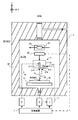
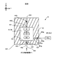
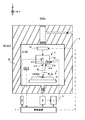
- FIG. 1 is a cross-sectional view showing the structure of the processing system of the first embodiment.
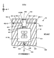
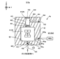
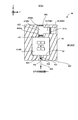
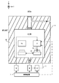
- FIG. 2 is a cross-sectional view showing the structure of the housing of the first embodiment.
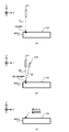
- FIGS. 3 (a) to 3 (c) is a cross-sectional view showing a state in which light is irradiated and a modeling material is supplied in a certain region on the work.
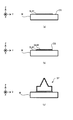
- FIGS. 4 (a) to 4 (c) is a cross-sectional view showing a process of forming a three-dimensional structure.
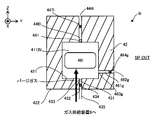
- FIG. 5 is a cross-sectional view showing the flow of purge gas before the machining system starts the machining operation.
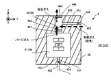
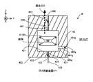
- FIG. 6 is a cross-sectional view showing the flow of purge gas while the machining system is performing the machining operation.
- FIG. 7 is a cross-sectional view showing the flow of purge gas after the machining system completes the machining operation.
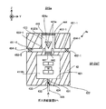
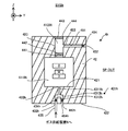
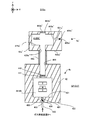
- FIG. 8 is a cross-sectional view showing the structure of the housing of the second embodiment.
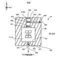
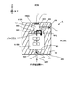
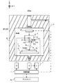
- FIG. 9 is a cross-sectional view showing the structure of the housing of the third embodiment.
- FIG. 10 is a cross-sectional view showing the structure of the housing of the fourth embodiment.
- FIG. 11 is a cross-sectional view showing the structure of the housing of the fifth embodiment.
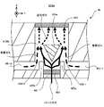
- FIG. 12 is a cross-sectional view showing the flow of purge gas in the mixed space of the housing of the fifth embodiment.
- FIG. 13 is a cross-sectional view showing the structure of the housing of the sixth embodiment.
- FIG. 14 is a cross-sectional view showing the structure of the housing of the seventh embodiment.
- FIG. 15 is a cross-sectional view showing the structure of the housing of the eighth embodiment.
- FIG. 16 is a cross-sectional view showing the structure of the processing system of the ninth embodiment.
- FIG. 17 is a cross-sectional view showing the structure of the housing of the tenth embodiment.
- FIG. 18 is a cross-sectional view showing the flow of purge gas while the machining system of the tenth embodiment is performing the machining operation.
- FIG. 19 is a cross-sectional view showing the structure of the housing of the eleventh embodiment.
- FIG. 20 is a cross-sectional view showing one step in which the purge gas in the machining space is discharged to the external space after the machining system in the eleventh embodiment completes the machining operation.
- FIG. 20 is a cross-sectional view showing one step in which the purge gas in the machining space is discharged to the external space after the machining system in the eleventh embodiment completes the machining operation.
- FIG. 21 is a cross-sectional view showing one step in which the purge gas in the machining space is discharged to the external space after the machining system in the eleventh embodiment completes the machining operation.
- FIG. 22 is a cross-sectional view showing one step in which the purge gas in the machining space is discharged to the external space after the machining system in the eleventh embodiment completes the machining operation.
- FIG. 23 is a cross-sectional view showing the structure of the housing of the twelfth embodiment.
- FIG. 24 is a cross-sectional view showing one step in which purge gas is supplied to the machining space before the machining system in the twelfth embodiment starts the machining operation.
- FIG. 25 is a cross-sectional view showing one step in which the purge gas in the machining space is discharged to the external space after the machining system in the twelfth embodiment completes the machining operation.
- FIG. 26 is a cross-sectional view showing one step in which the purge gas in the machining space is discharged to the external space after the machining system in the twelfth embodiment completes the machining operation.
- FIG. 27 is a cross-sectional view showing the structure of the processing system of the thirteenth embodiment.
- FIG. 28 is a cross-sectional view showing the structure of the processing system of the 14th embodiment.
- FIG. 29 is a cross-sectional view showing the structure of the housing of the fifteenth embodiment.
- FIG. 30 is a cross-sectional view showing the structure of the processing system of the 16th embodiment.
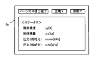
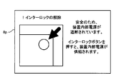
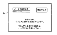
- FIG. 31 is a plan view showing a display example of system state information on the display.
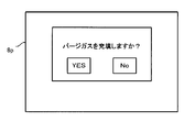
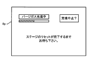
- FIG. 32 is a plan view showing a display example of filling information on the display.
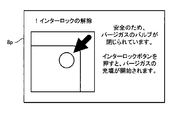
- FIG. 33 is a plan view showing a display example of filling information on the display.
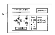
- FIG. 342 is a plan view showing a display example of filling information on the display.
- FIG. 35 is a plan view showing a display example of filling information on the display.
- FIG. 36 is a plan view showing a display example of filling information on the display.
- FIG. 37 is a plan view showing a display example of filling information on the display.
- FIG. 38 is a plan view showing a display example of filling information on the display.
- FIG. 39 is a plan view showing a display example of filling information on the display.
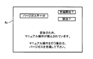
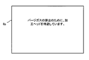
- FIG. 40 is a plan view showing a display example of emission information on a display.
- FIG. 41 is a plan view showing a display example of emission information on the display.
- FIG. 42 is a plan view showing a display example of emission information on the display.
- FIG. 43 is a plan view showing a display example of emission information on the display.
- the laser overlay welding method includes direct metal deposition, directed energy deposition, laser cladding, laser engineered net shaping, direct light fabrication, and laser consolidation.
- Foundation Shape Deposition Manufacturing, Wire-Feed Laser Deposition, Gas Through Wire, Laser Powder Fusion, Laser Metal Forming, Selective Laser Powder Remelting, Laser Direct It may also be referred to as casting, laser powder deposition, laser additive manufacturing, or laser rapid forming.
- each of the X-axis direction and the Y-axis direction is a horizontal direction (that is, a predetermined direction in the horizontal plane), and the Z-axis direction is a vertical direction (that is, a direction orthogonal to the horizontal plane). Yes, in effect, in the vertical direction).
- the rotation directions (in other words, the inclination direction) around the X-axis, the Y-axis, and the Z-axis are referred to as the ⁇ X direction, the ⁇ Y direction, and the ⁇ Z direction, respectively.
- the Z-axis direction may be the direction of gravity.
- the XY plane may be horizontal.
- machining system SYSa Processing system SYSSa of the first embodiment
- machining system SYSa the machining system SYS of the first embodiment
- machining system SYSa the machining system SYS of the first embodiment
- FIG. 1 is a cross-sectional view showing an example of the structure of the processing system SYSA of the first embodiment. However, for convenience of explanation, FIG. 1 does not show a cross section of the components of the processing system SYSTEM (specifically, the material supply device 1, the light source 5, the gas supply device 6 and the control device 7 described later). ..
- the processing system SYSa can form a three-dimensional structure ST (that is, a three-dimensional object having a size in any of the three-dimensional directions and a three-dimensional object).
- the processing system SYSa can form the three-dimensional structure ST on the work W that is the basis for forming the three-dimensional structure ST.
- This work W may be referred to as a base material or a pedestal.
- the processing system SYSa can form a three-dimensional structure ST by performing additional processing on the work W.
- the machining system SYSa can form the three-dimensional structure ST on the stage 31.
- the processing system SYSA puts the three-dimensional structure ST on the existing structure. It can be formed.
- the processing system SYSA may form a three-dimensional structure ST integrated with the existing structure.
- the operation of forming the three-dimensional structure ST integrated with the existing structure can be regarded as equivalent to the operation of adding a new structure to the existing structure.
- the existing structure may be, for example, a repair-required product having a defective portion.
- the processing system SYSa may form a three-dimensional structure in the repair-required product so as to fill the defective portion of the repair-required product.
- the processing system SYSA may form a three-dimensional structure ST that is separable from the existing structure.
- FIG. 1 shows an example in which the work W is an existing structure held by the stage 31. Further, in the following, the description will proceed with reference to an example in which the work W is an existing structure held by the stage 31.
- the processing system SYSa can form the three-dimensional structure ST by the laser overlay welding method. That is, it can be said that the processing system SYSa is a 3D printer that forms an object by using the laminated modeling technology.
- the laminated modeling technique is also referred to as rapid prototyping, rapid manufacturing, or additive manufacturing.
- the processing system SYSa supplies a material supply device 1, a processing device 2, a stage device 3, a housing 4, a light source 5, and a gas supply.
- a device 6 and a control device 7 are provided.
- the processing device 2 and the stage device 3 are housed in a processing space 411IN formed inside the housing 4. Therefore, the processing space 411IN is used as an accommodation space for accommodating the processing apparatus 2 and the stage apparatus 3 (furthermore, the work W held by the stage apparatus 3).
- the material supply device 1 supplies the modeling material M to the processing device 2.
- the material supply device 1 corresponds to the required amount so that the modeling material M required per unit time for the processing device 2 to form the three-dimensional structure ST is supplied to the processing device 2. A desired amount of modeling material M is supplied.
- the modeling material M is a material that can be melted by irradiation with a processing light EL having a predetermined intensity or higher.
- a modeling material M for example, at least one of a metallic material and a resin material can be used.
- the modeling material M a material different from the metallic material and the resin material may be used.
- the modeling material M is a powdery material. That is, the modeling material M is a powder.
- the powder may contain a granular material in addition to the powdery material.
- the modeling material M may contain, for example, a powder having a particle size within the range of 90 micrometers ⁇ 40 micrometers.
- the average particle size of the powder constituting the modeling material M may be, for example, 75 micrometers or any other size.
- the modeling material M does not have to be powder, and for example, a wire-shaped modeling material or a gaseous modeling material may be used.
- the processing device 2 forms the three-dimensional structure ST using the modeling material M supplied from the material supply device 1.
- the processing apparatus 2 includes a processing head 21 and a drive system 22.
- the processing head 21 includes an irradiation optical system 211 and a material nozzle (that is, a supply system for supplying the modeling material M) 212.
- the processing head 21 and the drive system 22 are housed in the processing space 411IN.
- the irradiation optical system 211 is an optical system (for example, a condensing optical system) for emitting the processed light EL from the injection unit 213. Specifically, the irradiation optical system 211 is optically connected to the light source 5 that emits the processed light EL via an optical transmission member (not shown) such as an optical fiber or a light pipe. The irradiation optical system 211 emits processed light EL propagating from the light source 5 via the optical transmission member. The irradiation optical system 211 emits the processing light EL so that the processing light EL advances in the processing space 411IN.
- an optical transmission member not shown
- the irradiation optical system 211 emits processed light EL propagating from the light source 5 via the optical transmission member.
- the irradiation optical system 211 emits the processing light EL so that the processing light EL advances in the processing space 411IN.
- the irradiation optical system 211 irradiates the processed light EL downward (that is, the ⁇ Z side) from the irradiation optical system 211.
- a stage 31 is arranged below the irradiation optical system 211.
- the irradiation optical system 211 irradiates the work W with the processing light EL.
- the irradiation optical system 211 can irradiate the irradiation area EA set on the work W as the area where the processing light EL is irradiated (typically, the light is focused). ..
- the state of the irradiation optical system 211 can be switched between a state in which the irradiation area EA is irradiated with the processing light EL and a state in which the irradiation area EA is not irradiated with the processing light EL under the control of the control device 7. ..
- the direction of the processed light EL emitted from the irradiation optical system 211 is not limited to directly below (that is, coincident with the ⁇ Z axis direction), and is, for example, a direction inclined by a predetermined angle with respect to the Z axis. May be good.
- the material nozzle 212 has a supply outlet 214 for supplying the modeling material M.
- the material nozzle 212 supplies the modeling material M from the supply outlet 214 (specifically, injection, ejection, and spraying). Therefore, the material nozzle 212 functions as a device for supplying the modeling material M together with the material supply device 1.
- the material nozzle 212 is physically connected to the supply source of the modeling material M included in the material supply device 1 via a material supply pipe 11 or the like included in the material supply device 1.
- the material nozzle 212 supplies the modeling material M supplied from the material supply device 1 via the material supply pipe 11.
- the material nozzle 212 may pump the modeling material M supplied from the material supply device 1 via the material supply pipe 11.
- the modeling material M from the material supply device 1 and a gas for transportation may be mixed and pumped to the material nozzle 212 via the material supply pipe 11.
- a gas for transportation for example, an inert gas such as nitrogen or argon
- the material nozzle 212 supplies the modeling material M toward the processing space 411IN.
- the material nozzle 212 supplies the modeling material M downward (that is, the ⁇ Z side) from the material nozzle 212.
- a stage 31 is arranged below the material nozzle 212. When the work W is mounted on the stage 31, the material nozzle 212 supplies the modeling material M toward the work W.
- the traveling direction of the modeling material M supplied from the material nozzle 212 is a direction inclined by a predetermined angle (an acute angle as an example) with respect to the Z-axis direction, but even if it is on the ⁇ Z side (that is, directly below). Good.
- the material nozzle 212 is aligned with the irradiation optical system 211 so that the irradiation optical system 211 supplies the modeling material M toward the irradiation region EA on which the processing light EL is irradiated. That is, the material nozzle 212 and the irradiation region 212 are irradiated so that the supply region MA and the irradiation region EA set on the work W as the region for supplying the modeling material M coincide with (or at least partially overlap) the material nozzle 212.
- the optical system 211 is aligned.
- the material nozzle 212 may be aligned so as to supply the modeling material M to the molten pool MP formed by the processing light EL emitted from the irradiation optical system 211.
- the drive system 22 moves the processing head 21.
- the drive system 22 moves the machining head 21 within the machining space 411IN, for example.
- the drive system 22 moves the machining head 21 along at least one of the X-axis, the Y-axis, and the Z-axis.
- the irradiation region EA moves on the work W along at least one of the X-axis and the Y-axis.
- the drive system 22 may move the machining head 21 along at least one rotation direction in the ⁇ X direction, the ⁇ Y direction, and the ⁇ Z direction in addition to at least one of the X-axis, the Y-axis, and the Z-axis.
- the drive system 22 may rotate the machining head 21 around at least one of the X-axis, Y-axis, and Z-axis.
- the drive system 22 may change the posture of the machining head 21 around at least one of the X-axis, the Y-axis, and the Z-axis.
- the drive system 22 includes an actuator such as a motor, for example.
- the irradiation optical system 211 and the material nozzle 212 may be moved separately.
- the drive system 22 may be able to adjust at least one of the position of the injection unit 213, the orientation of the injection unit 213, the position of the supply outlet 214, and the orientation of the supply outlet 214.
- the irradiation region EA where the irradiation optical system 211 irradiates the processing light EL and the supply region MA where the material nozzle 212 supplies the modeling material M can be controlled separately.
- the stage device 3 includes a stage 31.
- the stage 31 is housed in the chamber space 63IN.
- the stage 31 can support the work W.
- the state of "the stage 31 supporting the work W" here may mean a state in which the work W is directly or indirectly supported by the stage 31.
- the stage 31 may be able to hold the work W. That is, the stage 31 may support the work W by holding the work W. Alternatively, the stage 31 does not have to be able to hold the work W.
- the work W may be placed on the stage 31. That is, the stage 31 may support the work W placed on the stage 31. At this time, the work W may be mounted on the stage 31 without being clamped.
- the "stage 31 supporting the work W" state in the present embodiment may also include a state in which the stage 31 holds the work W and a state in which the work W is placed on the stage 31. Since the stage 31 is housed in the chamber space 63IN, the work W supported by the stage 31 is also housed in the chamber space 63IN. Further, the stage 31 can release the held work W when the work W is held.
- the irradiation optical system 211 described above irradiates the processed beam PL at least during a period in which the stage 31 supports the work W. Further, the material nozzle 212 described above supplies the modeling material M during at least a part of the period in which the stage 31 supports the work W.
- a part of the modeling material M supplied by the material nozzle 212 may be scattered or spilled from the surface of the work W to the outside of the work W (for example, around the stage 31). Therefore, the processing system SYSA may be provided with a recovery device for recovering the scattered or spilled modeling material M around the stage 31.
- the stage 31 may be provided with a mechanical chuck, a vacuum suction chuck, or the like in order to hold the work W.
- the stage 31 may be movable by a stage drive system (not shown in FIG. 1).
- the stage drive system may move the stage 31 within the processing space 411IN, for example.
- the stage drive system may move the stage 31 along at least one rotation direction of the X-axis, the Y-axis, and the Z-axis.
- the irradiation region EA moves on the work W along at least one of the X-axis and the Y-axis.
- the stage drive system may move the stage 31 along at least one of the ⁇ X direction, the ⁇ Y direction, and the ⁇ Z direction in addition to at least one of the X-axis, the Y-axis, and the Z-axis.
- the stage drive system 31 includes an actuator such as a motor, for example.
- the housing 4 is a storage device that accommodates at least the processing device 2, the stage device 3, and the work W in the processing space 411IN, which is the internal space of the housing 4.
- the housing 4 includes a partition member 42 that defines a processing space 411IN.
- the partition member 42 is a member that separates the processing space 411IN from the external space SP_OUT of the housing 4.
- the external space SP_OUT of the housing 4 is, for example, an atmospheric pressure space.
- the external space SP_OUT may include a space in which a user (operator) of the processing system SYSa enters. Since the structure of the housing 4 will be described with reference to FIG. 2, detailed description here will be omitted. Therefore, also in FIG. 1, the structure of the housing 4 is briefly described.
- the light source 5 emits, for example, at least one of infrared light and ultraviolet light as processed light EL.
- the processed light EL light of other wavelengths, for example, light having a wavelength in the visible region may be used.
- the processing light EL is a laser beam.
- the light source 5 may include a laser light source such as a semiconductor laser. Examples of the laser light source include at least one such as a laser diode (LD: Laser Diode), a fiber laser, a CO 2 laser, a YAG laser, and an excimer laser.
- the processing light EL does not have to be a laser beam, and the light source 5 may include an arbitrary light source (for example, at least one such as an LED (Light Emitting Side) and a discharge lamp).
- the gas supply device 6 is a supply source of purge gas for purging the processing space 411IN.
- the purge gas contains an inert gas.
- An example of the inert gas is nitrogen gas or argon gas.
- the gas supply device 6 supplies purge gas to the processing space 411IN.
- the gas supply device 6 may be a cylinder in which an inert gas such as nitrogen gas or argon gas is stored.
- the inert gas is nitrogen gas
- the gas supply device 6 may be a nitrogen gas generator that generates nitrogen gas from the atmosphere as a raw material.
- the processing space 411IN becomes a space purged by the purge gas.
- the space purged by the purge gas is a space filled with the purge gas (that is, a gas other than the purge gas (for example, oxygen gas) until the concentration thereof falls below a predetermined amount. It may mean an excluded space).
- the purge gas that is, a gas other than the purge gas (for example, oxygen gas) until the concentration thereof falls below a predetermined amount. It may mean an excluded space).
- the gas supply device 6 may further supply purge gas to the material supply device 1 (for example, the material supply pipe 11).
- the purge gas supplied to the material supply device 1 may be mainly used for pumping the modeling material M. Therefore, the gas supply device 6 can function as a device for supplying the modeling material M together with the material supply device 1. In this case, the gas supply device 6 may supply the pressurized purge gas to the material supply device 1.
- the supply of purge gas to the processing space 411IN and the supply of purge gas to the material supply device 1 may be controlled separately. That is, the gas supply device 6 may be able to individually supply the purge gas to each of the processing space 411IN and the material supply device 1. For example, the supply amount of purge gas per unit time to the processing space 411IN and the supply amount of purge gas per unit time to the material supply device 1 may be different.
- the gas supply device 6 supplies purge gas to either one of the processing space 411IN and the material supply device 1 in a state where the supply of the purge gas to one of the processing space 411IN and the material supply device 1 is stopped. You may.
- the gas supply device that supplies the purge gas to the processing space 411IN and the gas supply device that supplies the purge gas to the material supply device 1 may be different.
- the control device 7 controls the operation of the processing system SYS.
- the control device 7 may include, for example, a CPU (Central Processing Unit) (or a GPU (Graphics Processing Unit) in addition to or in place of the CPU) and a memory.
- the control device 7 functions as a device that controls the operation of the processing system SYS by the CPU executing a computer program.
- This computer program is a computer program for causing the control device 7 (for example, the CPU) to perform (that is, execute) the operation described later to be performed by the control device 7. That is, this computer program is a computer program for causing the control device 7 to function so that the processing system SYSa performs an operation described later.
- the computer program executed by the CPU may be recorded in a memory (that is, a recording medium) included in the control device 7, or may be an arbitrary storage medium built in the control device 7 or externally attached to the control device 7 (that is, a recording medium). For example, it may be recorded on a hard disk or a semiconductor memory). Alternatively, the CPU may download the computer program to be executed from a device external to the control device 7 via the network interface.
- a memory that is, a recording medium
- the CPU may download the computer program to be executed from a device external to the control device 7 via the network interface.
- the control device 7 may control the injection mode of the processed light EL by the irradiation optical system 211.
- the injection mode may include, for example, at least one of the intensity of the processing light EL and the injection timing of the processing light EL.
- the injection mode may include, for example, the ratio of the length of the emission time of the pulsed light to the emission period of the pulsed light (so-called duty ratio).
- the injection mode may include, for example, the length of the emission time of the pulsed light itself or the emission cycle itself.
- the control device 7 may control the movement mode of the processing head 21 by the drive system 22.
- the movement mode may include, for example, at least one of a movement amount, a movement speed, a movement direction, and a movement timing. Further, the control device 7 may control the supply mode of the modeling material M by the material nozzle 212.
- the supply mode may include, for example, at least one of a supply amount (particularly, a supply amount per unit time) and a supply timing.
- the control device 7 may not be provided inside the processing system SYS, and may be provided as a server or the like outside the processing system SYS, for example.
- the control device 7 and the processing system SYSA may be connected by a wired and / or wireless network (or a data bus and / or a communication line).
- a wired network for example, a network using a serial bus type interface represented by at least one of IEEE1394, RS-232x, RS-422, RS-423, RS-485 and USB may be used.
- a network using a parallel bus interface may be used.
- a network using an Ethernet (registered trademark) compliant interface represented by at least one of 10BASE-T, 100BASE-TX and 1000BASE-T may be used.
- a network using radio waves may be used.
- An example of a network using radio waves is a network conforming to IEEE802.1x (for example, at least one of wireless LAN and Bluetooth®).
- a network using infrared rays may be used.
- a network using optical communication may be used.
- the control device 7 and the processing system SYSA may be configured so that various types of information can be transmitted and received via the network. Further, the control device 7 may be able to transmit information such as commands and control parameters to the processing system SYSA via the network.
- the processing system SYSa may include a receiving device that receives information such as commands and control parameters from the control device 7 via the network.
- a part of the control device 7 may be provided inside the processing system SYSa, and a part of the control device 7 may be provided outside the processing system SYSa.
- Recording media for recording computer programs executed by the CPU include CD-ROMs, CD-Rs, CD-RWs, flexible disks, MOs, DVD-ROMs, DVD-RAMs, DVD-Rs, DVD + Rs, and DVD-RWs. , DVD + RW and Blu-ray (registered trademark) and other optical discs, magnetic tape and other magnetic media, magneto-optical disks, USB memory and other semiconductor memories, and any other medium that can store programs. May be good.
- the recording medium may include a device capable of recording a computer program (for example, a general-purpose device or a dedicated device in which the computer program is implemented in at least one form such as software and firmware).
- each process or function included in the computer program may be realized by a logical processing block realized in the control device 7 by the control device 7 (that is, a computer) executing the computer program. It may be realized by hardware such as a predetermined gate array (FPGA, ASIC) included in the control device 7, or a mixture of a logical processing block and a partial hardware module that realizes a part of the hardware. It may be realized in the form of.
- FPGA predetermined gate array
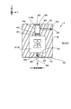
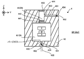
- FIG. 2 is a cross-sectional view showing the structure of the housing 4 of the first embodiment.
- the housing 4 includes a partition member 42 in which a processing space 411IN is formed.
- the partition member 42 includes an inner surface 421 that defines a processing space 411IN. In this case, the space surrounded by the inner surface 421 becomes the processing space 411IN.
- the processing space 411IN is a space for accommodating the processing apparatus 2, the stage apparatus 3, and the work W. Therefore, the processing space 411IN is also a space for the processing apparatus 2 to process the work W.
- the partition member 42 may be provided with a door that can be opened and closed. This door may be opened when the work W is placed on the stage 31 and when the work W and / or the modeled object is taken out from the stage 31, and may be closed during the modeling.
- the partition wall member 42 is formed with a through hole 431 that penetrates the partition wall member 42 from the inner surface 421 toward the outer surface 422 of the partition wall member 42. Since the outer surface 422 is the surface of the housing 4 facing the external space SP_OUT, the partition member 42 is also formed with a through hole 431 penetrating the partition member 42 from the processing space 411SP toward the external space SP_OUT. I can say.
- the through hole 431 is used as a supply pipe for the gas supply device 6 to supply the purge gas to the processing space 411IN. Therefore, in the following, the "through hole 431" will be referred to as a "supply pipe 431" as necessary.
- the through hole 431 forms a supply port 432 which is an opening on the outer surface 422 of the partition wall member 42.
- the gas supply device 6 and the supply port 432 are connected to each other via a supply pipe 435 extending in the external space SP_OUT.
- the through hole 431 forms a supply port 433 which is an opening on the inner surface 421 of the partition wall member 42. Therefore, the gas supply device 6 supplies the purge gas to the processing space 411IN via the supply pipe 435, the supply port 432, the supply pipe 431, and the supply port 433.
- a valve 434 is arranged in the supply pipe 431.
- the purge gas is supplied to the processing space 411IN via the valve 434. Therefore, the valve 434 can function as a supply device for supplying the purge gas to the processing space 411IN.
- the state of the valve 434 may be switched between a closed state in which the supply pipe 431 is closed and an open state in which the supply pipe 431 is opened under the control of the control device 7.
- the valve 434 is in the closed state, the purge gas is not supplied from the gas supply device 6 to the processing space 411IN via the supply pipe 431.
- the valve 434 is in the open state, purge gas can be supplied from the gas supply device 6 to the processing space 411IN via the supply pipe 431.
- the valve 434 may be able to adjust the supply amount of the purge gas supplied to the processing space 411IN via the supply pipe 431.
- the valve 434 may function as a device for adjusting the supply amount of the purge gas supplied to the processing space 411IN via the supply pipe 431.
- the control device 7 may set the supply amount of the purge gas to the first desired supply amount.
- the purge gas is supplied from the gas supply device 6 to the processing space 411IN via the valve 434 in the first desired supply amount.
- the control device 7 may change the supply amount of the purge gas from the first desired supply amount to the second desired supply amount. In this case, the purge gas is supplied from the gas supply device 6 to the processing space 411IN via the valve 434 in a second desired supply amount.
- a mixing space 412IN is further formed inside the housing 4 (that is, inside the partition member 42).
- the partition member 42 includes an inner surface 423 that defines the mixing space 412IN.
- the space surrounded by the inner surface 423 becomes the mixed space 412IN.
- the mixed space 412IN is a space different from the processing space 411IN.
- the mixed space 412IN is a space that does not include the processing space 411IN.
- the mixed space 412IN is a space in which the gas in the processing space 411IN flows in (that is, is supplied).
- the mixing space 412IN is connected to the processing space 411IN.
- a space for example, a pipeline in the supply pipe
- the mixing space 412IN is connected to the processing space 411IN so that the gas in the processing space 411IN can be supplied from the processing space 411IN to the mixing space 412IN.
- the processing space 411IN is a space purged by the purge gas. Therefore, the gas in the processing space 411IN is mainly purge gas.
- the gas in the processing space 411IN may contain a gas different from the purge gas.
- a gas different from the purge gas residual gas described later
- the description will proceed with reference to an example in which the gas flowing from the processing space 411IN into the mixing space 412IN is a purge gas.
- a filter 441 is arranged at the boundary between the mixed space 412IN and the processing space 411IN (or in the vicinity of the boundary). Therefore, the purge gas in the processing space 411IN is supplied from the processing space 411IN to the mixing space 412IN via the filter 441.
- the filter 441 adsorbs unnecessary substances contained in the purge gas.
- the unnecessary substance at least one of a substance used for the processing operation (for example, modeling material M) and a substance generated due to the processing operation (for example, fume) can be mentioned.
- An example of the filter 441 that adsorbs unnecessary substances is a HEPA (High Effectivey Particulate Air) filter.
- a blower 442 is further arranged at the boundary (or near the boundary) between the mixing space 412IN and the processing space 411IN. Therefore, the purge gas in the processing space 411IN is supplied from the processing space 411IN to the mixing space 412IN via the blower 442. Under the control of the control device 7, the blower 442 rotates the impeller or the like included in the blower 442 to send purge gas from the processing space 411IN to the mixing space 412IN.
- the blower 442 can function as a supply device for supplying purge gas from the processing space 411IN to the mixing space 412IN.
- the state of the blower 442 is between a state in which the purge gas is supplied from the processing space 411IN to the mixing space 412IN via the blower 442 and a state in which the purge gas is not supplied from the processing space 411IN to the mixing space 412IN via the blower 442. It may be switched.
- the blower 442 may further adjust the supply amount of the purge gas supplied from the processing space 411IN to the mixing space 412IN. That is, the blower 442 may be able to adjust the flow rate of the purge gas flowing from the processing space 411IN into the mixing space 412IN.
- the blower 442 adjusts the supply amount of the purge gas supplied from the processing space 411IN to the mixing space 412IN by adjusting the rotation speed of the impeller or the like included in the blower 442 under the control of the control device 7. May be good.
- the control device 7 may set the supply amount of the purge gas supplied from the processing space 411IN to the mixing space 412IN to a third desired supply amount. In this case, the purge gas is supplied from the processing space 411IN to the mixing space 412IN via the blower 442 in a third desired supply amount.
- the control device 7 may change the supply amount of the purge gas supplied from the processing space 411IN to the mixing space 412IN from the third desired supply amount to the fourth desired supply amount. In this case, the purge gas is supplied from the processing space 411IN to the mixing space 412IN via the blower 442 in a fourth desired supply amount.
- the blower 442 may function as a device for suppressing the purge gas sent out to the mixing space 412IN from flowing back into the processing space 411IN.
- the blower 442 can function substantially as a device for suppressing the purge gas sent out to the mixing space 412IN from flowing back into the processing space 411IN.
- At least one of the filter 441 and the blower 442 may be arranged between the mixing space 412IN and the processing space 411IN. At least one of the filter 441 and the blower 442 may be arranged in the mixing space 412IN. At least one of the filter 441 and the blower 442 may be arranged in the processing space 411IN. In any case, as long as each of the filter 441 and the blower 442 is arranged at the boundary (or near) between the processing space 411IN and the mixing space 412IN, the filter 411 and the blower 422 are used. The purge gas is still supplied from the processing space 411IN to the mixing space 412IN.
- the mixing space 412IN is a space in which the purge gas supplied from the processing space 411IN is diluted. Therefore, the mixing space 412IN may be referred to as a dilution space for diluting the purge gas supplied from the processing space 411IN.
- the purge gas is diluted by mixing with the diluent gas for dilution in the mixing space 412IN.
- the mixing space 412IN is a space in which the purge gas supplied from the processing space 411IN is mixed with the diluting gas.
- the dilution gas may be a gas containing at least oxygen.
- the diluting gas may be oxygen gas.
- the diluent gas may be air.
- the diluent gas does not cause any harm to the user even if the user (for example, a human) of the processing system SYSa inhales the purge gas mixed with the dilution gas (that is, the purge gas mixed with the dilution gas is the user). It may be a gas that satisfies the condition (become harmless to the gas).
- Each of the oxygen gas and air described above is an example of a gas satisfying this condition.
- the diluent gas is supplied to the mixing space 412IN in addition to the purge gas.
- the partition member 42 is formed with a through hole 451 that penetrates the partition member 42 from the inner surface 423 of the partition member 42 toward the outer surface 422 of the partition member 42. That is, the partition wall member 42 is formed with a through hole 451 that penetrates the partition wall member 42 from the mixing space 412IN toward the external space SP_OUT.
- the through hole 451 is used as a supply pipe for supplying the diluted gas from the external space SP_OUT to the mixing space 412IN.
- the "through hole 451” will be referred to as a "supply pipe 451” as necessary.
- the through hole 451 forms an intake port 452, which is an opening, on the outer surface 422 of the partition member 42.
- the through hole 451 forms an opening supply port 453 on the inner surface 423 of the partition member 42. Therefore, the diluted gas is supplied to the mixing space 412IN via the intake port 452, the supply pipe 451 and the supply port 453.
- the gas in the external space SP_OUT is used as the diluent gas.
- the air in the external space SP_OUT is used as a diluent gas. Therefore, the air in the external space SP_OUT is supplied to the mixing space 412IN as a diluting gas (in other words, inflows) through the intake port 452, the supply pipe 451 and the supply port 453.
- a valve 454 is arranged in the supply pipe 451.
- the diluent gas is supplied to the mixing space 412IN via the valve 454. Therefore, the valve 454 can function as a supply device for supplying the diluted gas to the mixing space 412IN.
- the state of the valve 454 may be switched between a closed state in which the supply pipe 451 is closed and an open state in which the supply pipe 451 is opened under the control of the control device 7.
- the valve 454 is in the closed state, the diluted gas is not supplied from the external space SP_OUT to the mixing space 412IN via the supply pipe 451.
- the purge gas in the mixing space 412IN is introduced into the external space via the supply pipe 451. It is not discharged (that is, discharged) to SP_OUT.
- the valve 454 when the valve 454 is in the open state, the diluted gas can be supplied from the external space SP_OUT to the mixing space 412IN via the supply pipe 451. Further, when the valve 454 is in the open state, the valve 454 may be able to adjust the supply amount of the diluent gas supplied to the mixing space 412IN via the supply pipe 451. That is, the valve 454 may function as a device for adjusting the supply amount of the diluent gas supplied to the mixing space 412IN via the supply pipe 451. For example, the control device 7 may set the supply amount of the diluent gas to the fifth desired supply amount.
- the diluted gas is supplied from the external space SP_OUT to the mixing space 412 IN via the valve 454 in a fifth desired supply amount.
- the control device 7 may change the supply amount of the diluent gas from the fifth desired supply amount to the sixth desired supply amount.
- the diluted gas is supplied from the external space SP_OUT to the mixing space 412 IN via the valve 454 in a sixth desired supply amount.
- the gas in the mixed space 412IN is discharged (that is, released) from the mixed space 412IN toward the external space SP_OUT.
- the purge gas and the diluent gas are mixed. Therefore, the gas in the mixing space 412IN includes a purge gas mixed with the diluting gas in the mixing space 412IN (that is, the diluted purge gas, hereinafter referred to as “mixed gas”). That is, the mixed gas is discharged from the mixed space 412IN toward the external space SP_OUT.
- the mixed gas may be discharged from the mixed space 412IN toward the external space SP_OUT through the exhaust port 444, which is an opening formed in the outer surface 422 of the partition wall member 42 by the mixed space 412IN.
- the mixed gas may be discharged from the mixing space 412IN toward the external space SP_OUT through an exhaust pipe and an exhaust port 444 (not shown) connecting the mixing space 412IN and the exhaust port 444. That is, a space (for example, a pipeline in the supply pipe) for connecting the mixed space 412IN and the external space SP_OUT may or may not be arranged between the mixed space 412IN and the external space SP_OUT. May be good.
- the mixed space 412IN is connected to the external space SP_OUT. Even if the mixed gas is released in this way, the mixed gas is harmless to the human being in the external space SP_OUT because the purge gas is a gas diluted with the diluting gas.
- the purge gas supplied to the processing space 411IN is mixed with the diluting gas in the mixing space 412IN secured in the path from the processing space 411IN to the exhaust port 444, and then discharged as a mixed gas from the exhaust port 444.
- the purge gas supplied to the processing space 411IN is mixed with the diluting gas in at least a part of the path from the processing space 411IN to the exhaust port 444, and then discharged as a mixed gas from the exhaust port 444.
- the state in which the mixed gas is discharged from the mixed space 412IN to the external space SP_OUT is substantially equivalent to the state in which the mixed space 412IN is open to the atmosphere. .. Furthermore, since the mixing space 412IN is connected to the processing space 411IN, the state in which the mixed gas is discharged from the processing space 411IN to the external space SP_OUT via the mixing space 412IN is substantially the processing space 411IN. It is equivalent to the state of being open to the atmosphere. That is, it can be said that the processing system SYSa discharges the mixed gas from the processing space 411IN to the external space SP_OUT via the mixing space 412IN by opening the processing space 411IN and the mixing space 412IN to the atmosphere.
- the exhaust port 444 is located from the processing space 411IN rather than the position where the flow path of the purge gas supplied from the processing space 411IN to the mixing space 412IN and the flow path of the dilution gas supplied from the external space SP_OUT to the mixing space 412IN intersect. It may be formed on the far side (that is, the side far from the blower 442). That is, in the exhaust port 444, the flow path of the purge gas supplied from the processing space 411IN to the mixing space 412IN and the flow path of the diluted gas supplied from the external space SP_OUT to the mixing space 412IN are the exhaust port 444 and the blower 443. It may be formed so as to intersect between the two. In this case, the purge gas diluted by the diluting gas is easily discharged from the exhaust port 444. That is, the purge gas that has not been diluted by the diluted gas is less likely to be discharged from the exhaust port 444.
- a blower 443 is further arranged at the boundary (or its vicinity) between the mixed space 412IN and the external space SP_OUT.
- An exhaust port 444 is formed between the mixed space 412IN and the external space SP_OUT. Therefore, the blower 443 may be arranged in the vicinity of the exhaust port 444 or the exhaust port 444.
- the mixed gas in the mixing space 412IN is discharged from the mixing space 412IN to the external space SP_OUT via the blower 443.
- the blower 443 sends the mixed gas from the mixing space 412IN to the external space SP_OUT by rotating the impeller or the like included in the blower 443 under the control of the control device 7.
- the blower 443 can function as a discharge device for discharging the mixed gas from the mixing space 412IN to the external space SP_OUT.
- the state of the blower 443 is a state in which the mixed gas is discharged from the mixing space 412IN to the external space SP_OUT via the blower 443 and a state in which the mixed gas is not discharged from the mixing space 412IN to the external space SP_OUT via the blower 443. It may be switched between.
- the blower 443 may further adjust the flow rate of the purge gas discharged from the mixing space 412IN to the external space SP_OUT. That is, the blower 443 may function as a discharge amount adjusting device for adjusting the discharge amount of the mixed gas from the mixing space 412IN to the external space SP_OUT.
- the blower 443 adjusts the flow rate of the mixed gas discharged from the mixing space 412IN to the external space SP_OUT by adjusting the rotation speed of the impeller or the like included in the blower 443 under the control of the control device 7. May be good.
- the control device 7 may set the discharge amount of the mixed gas discharged from the mixing space 412IN to the external space SP_OUT to the first desired discharge amount. In this case, the mixed gas is discharged from the mixing space 412IN to the external space SP_OUT via the blower 443 at the first desired discharge amount.
- the control device 7 may change the discharge amount of the mixed gas discharged from the mixing space 412IN to the external space SP_OUT from the first desired discharge amount to the second desired discharge amount. In this case, the mixed gas is discharged from the mixing space 412IN to the external space SP_OUT via the blower 443 with a second desired discharge amount.
- the blower 443 may be arranged between the mixed space 412IN and the external space SP_OUT.
- the blower 443 may be arranged in the mixing space 412IN.
- the blower 443 may be arranged in the external space SP_OUT. In any case, as long as the blower 443 is located at the boundary (or near) between the mixed space 412IN and the external space SP_OUT, the mixed space 412IN is transferred to the external space SP_OUT via the blower 423. On the other hand, the mixed gas is still discharged.
- the processing system SYSa forms the three-dimensional structure ST on the work W based on the three-dimensional model data (for example, CAD (Computer Aided Design) data) of the three-dimensional structure ST to be formed.
- 3D model data measurement data of a three-dimensional object measured by a measuring device (not shown) provided in the processing system SYS, and a 3D shape measuring machine provided separately from the processing system SYS, for example, a work W.
- a contact type 3D coordinate measuring machine having a probe that can move and contact the work W, and a non-contact type 3D measuring machine (for example, a pattern projection type 3D measuring machine and an optical cutting type 3D measuring machine).
- Time of flight 3D measuring machine Time of flight 3D measuring machine, Moiretopography 3D measuring machine, Holographic interference 3D measuring machine, CT (Computed Tomography) 3D measuring machine, MRI (Magnetic response imaging)
- CT Computer Tomography
- MRI Magnetic response imaging
- STL Starteo Lithology
- VRML Virtual Reality Modeling Language
- AMF Adaptive Manufacture
- AMF Adaptive Manufacture
- IGES Initial Graphics Equipment Specialization
- VDA-FS Association of Germany Automatic Manufactures-Surfaces Interface
- HP / GL Power
- a plurality of layered partial structures hereinafter referred to as "structural layers" SLs arranged along the Z-axis direction are sequentially formed, for example, a processing system.
- SYSSa sequentially forms a plurality of structural layer SLs obtained by slicing the three-dimensional structure ST along the Z-axis direction, one layer at a time. As a result, the plurality of structural layers SL are laminated.
- the three-dimensional structure ST which is a structure is formed.
- the flow of the operation of forming the three-dimensional structure ST by sequentially forming a plurality of structural layers SL one by one will be described.
- the processing system SYSa sets an irradiation region EA in a desired region on the modeling surface CS corresponding to the surface of the work W or the surface of the formed structural layer SL, and sets the irradiation region EA for the irradiation region EA.
- the processing light EL is irradiated from the irradiation optical system 211.
- the region occupied by the processed light EL emitted from the irradiation optical system 211 on the modeling surface CS may be referred to as an irradiation region EA.
- the focus position (that is, the condensing position) of the processed light EL coincides with the modeling surface CS.
- a molten pool (that is, a pool of metal melted by the processing light EL) MP is formed in a desired region on the modeling surface CS by the processing light EL emitted from the irradiation optical system 211. It is formed.
- the processing system SYSA sets a supply region MA in a desired region on the modeling surface CS under the control of the control device 7, and supplies the modeling material M to the supply region MA from the material nozzle 212.
- the processing system SYSa supplies the modeling material M to the molten pool MP from the material nozzle 212.
- the modeling material M supplied to the molten pool MP melts.
- the processing light EL is no longer irradiated to the molten pool MP as the processing head 21 moves, the modeling material M melted in the molten pool MP is cooled and solidified (that is, solidified) again.
- the solidified modeling material M is deposited on the modeling surface CS. That is, a modeled object is formed by the deposit of the solidified modeling material M.
- a series of modeling processes including formation of the molten pool MP by such light irradiation EL, supply of the modeling material M to the molten pool MP, melting of the supplied modeling material M, and solidification of the molten modeling material M are performed.
- the processing head 21 is repeatedly moved relative to the surface CS along the XY plane. That is, when the processing head 21 moves relative to the modeling surface CS, the irradiation region EA also moves relative to the modeling surface CS. Therefore, a series of modeling processes is repeated while moving the irradiation region EA relative to the modeling surface CS along the XY plane (that is, in the two-dimensional plane).
- the processed light EL is selectively irradiated to the irradiation region EA set in the region where the modeled object is to be formed on the modeling surface CS, but it is not desired to form the modeled object on the modeling surface CS.
- the irradiation area EA set in the area is not selectively irradiated (it can be said that the irradiation area EA is not set in the area where the modeled object is not desired to be formed). That is, the processing system SYSa moves the irradiation region EA along the predetermined movement locus on the modeling surface CS, and transfers the processing light EL to the modeling surface CS at a timing according to the distribution mode of the region where the modeled object is to be formed.
- the mode of distribution of the region where the modeled object is to be formed may be referred to as a distribution pattern or a pattern of the structural layer SL.
- the molten pool MP also moves on the modeling surface CS along the movement locus according to the movement locus of the irradiation region EA.
- the molten pool MP is sequentially formed on the modeling surface CS in the portion of the region along the movement locus of the irradiation region EA that is irradiated with the processing light EL.
- the supply region MA also moves on the modeling surface CS along the movement locus according to the movement locus of the irradiation region EA.
- a structural layer SL corresponding to an aggregate of the modeled objects made of the solidified modeling material M is formed on the modeling surface CS. That is, the structural layer SL corresponding to the aggregate of the shaped objects formed on the modeling surface CS in the pattern corresponding to the moving locus of the molten pool MP (that is, the shape corresponding to the moving locus of the molten pool MP in a plan view).
- the structural layer SL) to have is formed.
- the processing light EL may be irradiated to the irradiation region EA and the supply of the modeling material M may be stopped. Further, when the irradiation region EA is set in the region where the modeled object is not to be formed, the modeling material M is supplied to the irradiation region EL, and the irradiation region EL is irradiated with the processing light EL having a strength that does not allow the molten pool MP. You may.
- the processing system SYSa moves the processing head 21 with respect to the modeling surface CS (that is, moves the processing light EL) to move the irradiation region EA with respect to the modeling surface CS.
- the machining system SYSa moves the stage 31 with respect to the machining head 21 (that is, moves the modeling surface CS).
- the irradiation area EA may be moved with respect to the modeling surface CS.
- the processing system SYSa repeatedly performs the operation for forming such a structural layer SL under the control of the control device 7 based on the three-dimensional model data. Specifically, first, the three-dimensional model data is sliced at a stacking pitch to create slice data. In addition, you may use the data which partially modified this slice data according to the characteristic of the processing system SYSa.
- the processing system SYSa performs an operation for forming the first structural layer SL # 1 on the modeling surface CS corresponding to the surface of the work W with three-dimensional model data corresponding to the structural layer SL # 1, that is, the structural layer. This is performed based on the slice data corresponding to SL # 1. As a result, the structural layer SL # 1 is formed on the modeling surface CS as shown in FIG.
- the processing system SYSa sets the surface (that is, the upper surface) of the structural layer SL # 1 on the new modeling surface CS, and then forms the second structural layer SL # 2 on the new modeling surface CS.
- the control device 7 first controls the drive system 22 so that the machining head 21 moves along the Z axis. Specifically, the control device 7 controls the drive system 22 so that the irradiation region EA and the supply region MA are set on the surface of the structural layer SL # 1 (that is, the new modeling surface CS) + Z.
- the processing head 21 is moved toward the side. As a result, the focus position of the processed light EL coincides with the new modeling surface CS.
- the processing system SYSa operates on the structural layer SL # 1 based on the slice data corresponding to the structural layer SL # 2 in the same operation as the operation of forming the structural layer SL # 1 under the control of the control device 7.
- the structural layer SL # 2 is formed on the surface.
- the structural layer SL # 2 is formed as shown in FIG. 4 (b).
- the same operation is repeated until all the structural layers SL constituting the three-dimensional structure ST to be formed on the work W are formed.
- the three-dimensional structure ST is formed by the laminated structure in which a plurality of structural layers SL are laminated.
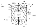
- FIG. 5 is a cross-sectional view showing the flow of purge gas before the machining system SYSA starts the machining operation.
- the purge gas is supplied to the machining space 411IN so that the machining space 411IN becomes a space purged by the purge gas.
- the state of the valve 434 is set to the open state under the control of the control device 7.
- purge gas is supplied from the gas supply device 6 to the processing space 411IN via the supply pipe 435, the supply port 432, the supply pipe 431, and the supply port 433.
- a gas other than the purge gas exists in the processing space 411IN.
- the gas existing (that is, remaining) in the processing space 411IN before the processing space 411IN is purged by the purge gas is referred to as “residual gas”. Therefore, with the supply of the purge gas to the processing space 411IN, the residual gas is discharged from the processing space 411IN to the mixing space 412IN.
- the blower 442 may operate in order to accelerate the discharge of the residual gas from the processing space 411IN to the mixing space 412IN.
- the blower 442 may operate so that the gas (particularly, the residual gas) in the processing space 411IN is discharged from the processing space 411IN to the mixing space 412IN. Further, the blower 443 may also operate in order to accelerate the discharge of the residual gas discharged to the mixing space 412IN from the mixing space 412IN to the external space SP_OUT. That is, the blower 443 may operate so that the gas (particularly, the residual gas) in the mixing space 412IN is discharged from the mixing space 412IN to the external space SP_OUT.
- a diluting gas for example, air
- the state of the valve 454 may be set to the open state under the control of the control device 7.
- the diluted gas is supplied from the external space SP_OUT to the mixing space 412IN via the intake port 452, the supply pipe 451 and the supply port 453.
- Mixing of the purge gas and the diluent gas in the mixing space 412IN may be performed for the purpose of preventing oxygen deficiency in the external space SP_OUT. For example, if the first dilution condition that the concentration of oxygen in the mixed gas in which the purge gas and the diluted gas are mixed becomes equal to or higher than the allowable lower limit value (for example, 18%) is satisfied, the mixed gas is released to the external space SP_OUT. Even so, oxygen deficiency in the external space SP_OUT can be prevented.
- the allowable lower limit value for example, 18%
- the mixed gas becomes Even if it is released into the external space SP_OUT, oxygen deficiency in the external space SP_OUT can be prevented.
- the third dilution condition that the concentration of the purge gas in the mixed gas becomes equal to or less than the allowable upper limit value is satisfied, oxygen deficiency in the external space SP_OUT can be prevented even if the mixed gas is released into the external space SP_OUT.
- the purge gas and the dilution gas may be mixed in the mixing space 412 IN so that at least one of these first to third dilution conditions is satisfied.
- the purge gas and the dilution gas may be mixed in the mixing space 412IN so that the mixed gas is released into the external space SP_OUT after at least one of the first to third dilution conditions is satisfied.
- the processing space 411IN is changed to the mixing space 412IN.
- the concentration of oxygen in the mixed gas becomes 18% or more.
- the mixing mode of the purge gas and the dilution gas is mainly the state of the valve 454 (that is, the amount of the dilution gas supplied through the supply pipe 451) and the state of the blower 442 (that is, the purge gas from the processing space 411IN to the mixing space 412IN). It depends on the supply amount) and the state of the blower 443 (that is, the discharge amount of the mixed gas from the mixing space 412IN to the external space SP_OUT).
- the state of the valve 454 mainly affects the amount of diluted gas supplied through the supply pipe 451.
- the state of the blower 442 mainly affects the supply amount of purge gas from the processing space 411IN to the mixing space 412IN.
- the state of the blower 443 mainly affects the amount of the mixed gas discharged from the mixed space 412IN to the external space SP_OUT. Therefore, the control device 7 may control at least one state of the valve 454, the blower 442 and the blower 443 so that at least one of the first to third dilution conditions is satisfied. The control device 7 controls at least one state of the valve 454, the blower 442, and the blower 443 so that the mixed gas is discharged to the external space SP_OUT after at least one of the first to third dilution conditions is satisfied. May be good.
- the mixed gas is discharged from the mixing space 412IN to the external space SP_OUT via the blower 443.
- the purge gas in the machining space 411IN is not positively supplied to the mixing space 412IN. That is, before the machining system SYSA starts the machining operation, the purge gas in the machining space 411IN is not originally supplied to the mixing space 412IN. On the other hand, after the machining system SYSa completes the machining operation, the purge gas in the machining space 411IN is positively supplied to the mixing space 412IN in order to discharge the purge gas in the machining space 411IN to the external space SP_OUT.
- the amount of purge gas supplied from the machining space 411IN to the mixing space 412IN before the machining system SYSa starts the machining operation is the purge gas from the machining space 411IN to the mixing space 412IN after the machining system SYSa completes the machining operation. May be less than the supply of. Therefore, the amount of dilution gas supplied to the mixing space 412IN before the processing system SYSa starts the processing operation is based on the amount of dilution gas supplied to the mixing space 412IN after the processing system SYSa has completed the processing operation, which will be described later. May be less.
- the discharge amount of the mixed gas from the mixing space 412IN to the external space SP_OUT may also be small, so that the processing system SYSA operates.
- the amount of mixed gas discharged from the mixed space 412IN to the external space SP_OUT before starting is smaller than the amount of mixed gas discharged from the mixed space 412IN to the external space SP_OUT after the processing system SYSa completes the machining operation. May be good.
- FIG. 6 is a cross-sectional view showing the flow of purge gas while the processing system SYSA is performing the processing operation.
- the purge gas is not supplied to the mixing space 412IN, the need to dilute the purge gas with the dilution gas in the mixing space 412IN is relatively low. Therefore, while the machining system SYSA is performing the machining operation, the supply of the diluent gas from the external space SP_OUT to the mixing space 412IN may be stopped. That is, the diluting gas does not have to be supplied from the external space SP_OUT to the mixing space 412IN. Therefore, the state of the valve 454 may be set to the closed state under the control of the control device 7.
- the blower 443 may be stopped while the processing system SYSA is performing the processing operation. If the blower 443 is stopped together with the blower 442, it is unlikely that the purge gas will be supplied from the processing space 411IN to the mixing space 412IN and the purge gas will be discharged from the mixing space 412IN to the external space SP_OUT.
- purge gas may be supplied to the processing space 411IN while the processing system SYSA is performing the processing operation.
- the processing system SYSa is equipped with a gas supply device that prevents substances from adhering to the optical surface by blowing purge gas onto the optical surface of the optical member included in the irradiation optical system 211, the processing system SYSa processes it.
- purge gas may be supplied to the machining space 411IN.
- the substance that may adhere to the optical surface at least one of a substance used for the processing operation (for example, modeling material M) and a substance generated due to the processing operation (for example, fume) can be mentioned. ..
- the purge gas used for pumping may be supplied to the processing space 411IN via the supply outlet 214 of the material nozzle 212.
- the same operation as before the machining system SYSa starts the machining operation may be performed. That is, the respective states of the valves 434 and 454 may be set to the open state, and the blowers 442 and 443 may operate respectively.
- the machining space 411IN is a space purged with purge gas. That is, while the machining system SYSA is performing the machining operation, there is almost no residual gas in the machining space 411IN. Therefore, the supply amount of the purge gas supplied to the machining space 411IN while the machining system SYSa is performing the machining operation is the supply amount of the purge gas supplied to the machining space 411IN before the machining system SYSa starts the machining operation. (That is, the amount of purge gas supplied to the processing space 411IN where the residual gas exists) is less than.
- each of the blowers 442 and 443 may operate so that an excessively large amount of purge gas is not supplied from the processing space 411IN to the mixing space 412IN.
- Each of the blowers 442 and 443 may operate so that an excessively large amount of purge gas is not discharged from the processing space 411IN to the external space SP_OUT via the mixing space 412IN.
- the blower 443 may operate with the same or weaker blowing capacity (in other words, supply capacity or discharge capacity) as before the processing system SYSA starts the processing operation, while the blower 442 may stop.
- the blower 443 operates with a weaker blowing capacity than before the machining system SYSa starts the machining operation
- the blower 442 operates with the same or weaker blowing capacity as before the machining system SYSa starts the machining operation.
- the supply of purge gas supplied from the machining space 411IN to the mixing space 412IN is compared with the case where both the blowers 442 and 443 are operating with the same blowing capacity as before the machining system SYSa starts the machining operation. The amount will be small. Further, the discharge flow rate of the purge gas (specifically, the diluted purge gas) discharged from the processing space 411IN to the external space SP_OUT via the mixing space 412IN is reduced. Therefore, it becomes difficult to supply an excessively large amount of purge gas from the processing space 411IN to the mixing space 412IN.
- the control device 7 supplies the diluted gas through the supply pipe 451 from the processing space 411IN based on the gas supply information regarding the supply of the purge gas to the processing space 411IN. At least one of the supply amount of the purge gas to the mixing space 412IN and the supply amount of the purge gas from the mixing space 412IN to the external space SP_OUT may be adjusted. That is, the control device 7 may control at least one state of the valve 454, the blower 442, and the blower 443 based on the gas supply information.
- the gas supply information may include, for example, information regarding at least one of the purge gas supply amount (for example, the supply amount per unit time) and the purge gas pressure by the gas supply device 6.
- the gas supply information may include information about the pressure at which the gas supply device 6 and the material supply device 1 pump the modeling material M.
- the control device 7 supplies the diluted gas through the supply pipe 451 and the processing space based on the material supply information regarding the supply of the modeling material M to the processing space 411IN. At least one of the supply amount of the purge gas from the 411IN to the mixing space 412IN and the supply amount of the purge gas from the mixing space 412IN to the external space SP_OUT may be adjusted.
- the material supply information may include information regarding the supply amount (for example, the supply amount per unit time) of the modeling material M by the material supply device 1.
- FIG. 7 is a cross-sectional view showing the flow of purge gas after the machining system SYSA completes the machining operation.
- the work W (specifically, the work W in which the three-dimensional structure ST is formed by the machining operation) is usually taken out from the machining space 411IN. Therefore, the purge gas purging the processing space 411IN is discharged from the processing space 411IN.
- the state of the valve 434 is set to the closed state under the control of the control device 7 in order to stop the supply of the purge gas to the machining space 411IN. As a result, the purge gas is not newly supplied from the gas supply device 6 to the processing space 411IN.
- the state of the valve 454 is set to the open state, and the blowers 442 and 443 operate respectively.
- the purge gas in the processing space 411IN is supplied from the processing space 411IN to the mixing space 412IN.
- the air in the external space SP_OUT that is, the diluting gas
- the mixing space 412IN the purge gas and the diluent gas are mixed.
- the mixing of the purge gas and the diluent gas in the mixing space 412IN prevents oxygen deficiency in the external space SP_OUT as before the machining system SYSa starts the machining operation. It may be done for the purpose. As a result, the mixed gas is discharged from the mixing space 412IN to the external space SP_OUT via the blower 443.
- the material supply device 1 mixes the modeling material M and the purge gas for transportation and forms the material nozzle 212 via the material supply pipe 11.
- Supply material M Therefore, the purge gas may also be present in the space inside the material supply pipe 11. That is, there is a possibility that the purge gas is also present in the space for supplying the modeling material M from the material supply device 1 to the material nozzle 212. Therefore, the processing system SYSA may discharge the purge gas in the space for supplying the modeling material M from the material supply device 1 to the material nozzle 212 from the space to the external space SP_OUT.
- the processing system SYSa supplies the modeling material M from the material supply device 1 to the material nozzle 212 in the same manner as when the purge gas in the processing space 411IN is discharged from the processing space 411IN to the external space SP_OUT via the mixing space 412IN.
- the purge gas in the space for this purpose may be discharged from the space to the external space SP_OUT via the processing space 411IN and the mixing space 412IN.
- the processing system SYSa supplies the modeling material M from the material supply device 1 to the material nozzle 212 by using a path for discharging the purge gas in the processing space 411IN from the processing space 411IN to the external space SP_OUT via the mixing space 412IN.
- the purge gas in the space for the space may be discharged.
- the processing system SYSA may discharge the purge gas in the space for supplying the modeling material M from the material supply device 1 to the material nozzle 212 to the external space SP_OUT via the processing space 411IN and the mixing space 412IN.
- the purge gas in the space for supplying the modeling material M from the material supply device 1 to the material nozzle 212 is a supply outlet at one end of the material supply pipe 11 or connected to one end. It is discharged from the inside of the material supply pipe 11 to the processing space 411IN via 214.
- the processing system SYSa may discharge the purge gas in the space for supplying the modeling material M from the material supply device 1 to the material nozzle 212 from the space without passing through the processing space 411IN.
- the purge gas in the space for supplying the modeling material M from the material supply device 1 to the material nozzle 212 is the other end of the material supply pipe 11 (that is, the end opposite to the supply outlet 214). ) May be discharged from the inside of the material supply pipe 11.
- the processing system SYSa discharges the purge gas from the processing space 411IN and the purge gas in the space for supplying the modeling material M from the material supply device 1 to the material nozzle 212 (for example, inside the material supply pipe 11). It may be done individually. For example, the processing system SYSa has stopped discharging purge gas from either the processing space 411IN or the space for supplying the modeling material M from the material supply device 1 to the material nozzle 212, and the processing space 411IN and the material. Purge gas may be discharged from any one of the spaces for supplying the modeling material M from the supply device 1 to the material nozzle 212.
- the state in which the purge gas is discharged from the processing space 411IN to the external space SP_OUT is equivalent to the state in which the processing space 411IN is open to the atmosphere. Therefore, when the purge gas is discharged from the space for supplying the modeling material M from the material supply device 1 to the material nozzle 212 to the external space SP_OUT, the modeling material M is discharged from the material supply device 1 to the material nozzle 212. It is equivalent to the state where the space for supplying is open to the atmosphere. In this case, the processing system SYSA may individually open the processing space 411IN to the atmosphere and the space for supplying the modeling material M from the material supply device 1 to the material nozzle 212.
- the processing space 411IN and the material supply device 1 do not open any one of the spaces for supplying the modeling material M from the processing space 411IN and the material supply device 1 to the material nozzle 212 to the atmosphere. Either one or the other of the space for supplying the modeling material M to the material nozzle 212 may be opened to the atmosphere.
- the processing system SYSA may be provided with a blocking device 111 (see FIG. 1) capable of blocking the processing space 411IN and the space for supplying the modeling material M from the material supply device 1 to the material nozzle 212. ..
- the shutoff device 111 may include, for example, a valve capable of closing the material supply pipe 11.
- the blocking device 111 cuts off the processing space 411IN and the space for supplying the modeling material M from the material supply device 1 to the material nozzle 212, so that the processing space 411IN and the material supply device 1 to the material nozzle 212.
- one of the spaces for supplying the modeling material M to the air is not open to the atmosphere, and one of the spaces for supplying the modeling material M from the processing space 411IN and the material supply device 1 to the material nozzle 212 is the atmosphere. It may be opened.
- the processing system SYSa mixes the purge gas and the dilution gas inside the housing 4, and then discharges the mixed gas in which the purge gas and the dilution gas are mixed to the outside of the housing 4. That is, the processing system SYSa dilutes the purge gas with the diluting gas inside the housing 4, and then discharges the diluted purge gas to the outside of the housing 4.
- the mixing of the purge gas and the diluent gas in the mixing space 412IN is performed, for example, for the purpose of preventing oxygen deficiency in the external space SP_OUT.
- the processing system SYSa can release a mixed gas harmless to the user in the external space SP_OUT to the external space SP_OUT.
- the processing system SYSa can detoxify the purge gas inside the housing 4 and then discharge the detoxified purge gas (that is, the diluted purge gas) to the external space SP_OUT.
- the processing system SYSa can release a harmless mixed gas to the external space SP_OUT, the purge gas released by the processing system SYSa bypasses the space where the user exists and goes to the space where the user does not exist. It is not necessary to arrange a pipe (for example, a duct) for discharging. Therefore, the processing system SYSa can be easily handled. Further, the processing system SYSa can be miniaturized. Furthermore, the appearance of the processing system SYSa becomes neat.
- FIG. 8 is a cross-sectional view showing the structure of the housing 4b of the second embodiment.
- the constituent requirements already explained will be designated by the same reference numerals, and detailed description thereof will be omitted.
- the housing 4b of the second embodiment has a boundary (or a boundary) between the mixing space 412IN and the processing space 411IN as compared with the housing 4 of the first embodiment described above. It differs in that the valve 4451b is located in the vicinity). Further, in the housing 4b, the valve 4452b is arranged at the boundary between the mixed space 412IN and the external space SP_OUT (or near the boundary) or near the exhaust port 444 as compared with the housing 4. Different in that. Other features of the housing 4b may be the same as the other features of the housing 4.
- valve 4451b When the valve 4451b is arranged at the boundary between the mixing space 412IN and the processing space 411IN (or near the boundary), the purge gas of the processing space 411IN is introduced from the processing space 411IN to the mixing space via the valve 4451b. It is supplied to 412IN. Therefore, the valve 4451b can function as a supply device for supplying purge gas from the processing space 411IN to the mixing space 412IN.
- the state of the valve 4451b is a closed state in which the flow path between the machining space 411IN and the mixing space 412IN is closed and a flow path between the machining space 411IN and the mixing space 412IN is opened under the control of the control device 7. It can be switched between the open state and the open state.
- the purge gas or residual gas
- gas for example, at least one of the mixed gas and the diluted gas
- gas does not flow in (that is, is supplied) from the mixed space 412IN to the processing space 411IN.
- valve 4451b when the valve 4451b is in the open state, purge gas (or residual gas) can be supplied from the processing space 411IN to the mixing space 412IN. Further, when the valve 4451b is in the open state, the valve 4451b may be able to adjust the supply amount of the purge gas (or residual gas) supplied from the processing space 411IN to the mixing space 412. That is, the valve 4451b may function as a device for adjusting the supply amount of the purge gas (or residual gas) supplied from the processing space 411IN to the mixing space 412. For example, the control device 7 may set the supply amount of the purge gas to the seventh desired supply amount.
- the purge gas is supplied from the processing space 411IN to the mixing space 412IN via the valve 4451b in a seventh desired supply amount.
- the control device 7 may change the supply amount of the purge gas from the seventh desired supply amount to the eighth desired supply amount.
- the purge gas is supplied from the processing space 411IN to the mixing space 412IN via the valve 4451b in an eighth desired supply amount.
- valve 4452b When the valve 4452b is arranged at the boundary (or near the boundary) between the mixed space 412IN and the external space SP_OUT, the mixed gas of the mixed space 412IN is external from the mixed space 412IN via the valve 4452b. It is supplied to the space SP_OUT. Therefore, the valve 4451b can function as a discharge device for discharging the mixed gas from the mixing space 412IN to the external space SP_OUT.
- the state of the valve 4452b is a closed state in which the flow path between the mixing space 412IN and the external space SP_OUT is closed and a flow path between the mixing space 412IN and the external space SP_OUT is opened under the control of the control device 7. It can be switched between the open state and the open state.
- the valve 4452b is in the closed state, the mixed gas is not discharged from the mixing space 412IN to the external space SP_OUT.
- the valve 4452b is in the open state, the mixed gas can be discharged from the mixing space 412IN to the external space SP_OUT.
- the valve 4452b may be able to adjust the discharge amount of the mixed gas discharged from the mixing space 412IN to the external space SP_OUT. That is, the valve 4452b may function as a device for adjusting the discharge amount of the mixed gas discharged from the mixing space 412IN to the external space SP_OUT.
- the control device 7 may set the emission amount of the mixed gas to a third desired emission amount. In this case, the mixed gas is discharged from the mixing space 412IN to the external space SP_OUT via the valve 4452b at a third desired discharge amount.
- the control device 7 may change the emission amount of the mixed gas from the third desired emission amount to the fourth desired emission amount. In this case, the mixed gas is discharged from the mixing space 412IN to the external space SP_OUT via the valve 4452b at a fourth desired discharge amount.
- the respective states of the valves 4451b and 4452b may be set to the closed state while the machining system SYSa is performing the machining operation (see FIG. 6).
- the purge gas is not supplied from the processing space 411IN to the mixing space 412IN, and the purge gas is not discharged from the mixing space 412IN to the external space SP_OUT. That is, the housing 4b is less likely to have a situation in which purge gas is unintentionally discharged from the housing 4b to the external space SP_OUT as compared with the housing 4 which does not have to include the valves 4451b and 4452b.
- the processing system SYSb of the second embodiment more appropriately suppresses the discharge of unintended purge gas to the external space SP_OUT while enjoying the same effect as that of the processing system SYSa of the first embodiment. Can be done. That is, the processing system SYSb of the second embodiment can more appropriately suppress the oxygen deficiency of the user in the external space SP_OUT.
- FIG. 9 is a cross-sectional view showing the structure of the housing 4c of the third embodiment.
- the housing 4c of the third embodiment is different from the housing 4 of the first embodiment described above in that the gas tank 455c is arranged inside the housing 4c. Further, the housing 4c is different from the housing 4 in that the supply pipe 451 connects the mixing space 412IN and the gas tank 455c, and the supply pipe 451 connects the mixing space 412IN and the external space SP_OUT. Further, the housing 4c is different from the housing 4 in that the intake port 452 does not have to be formed. Other features of the housing 4c may be the same as the other features of the housing 4.
- the gas tank 455c is a storage device capable of storing diluted gas. Therefore, in the second embodiment, the diluted gas is supplied from the gas tank 455c to the mixing space 412IN via the supply pipe 451 and the supply port 453.
- a processing system SYSc of the third embodiment can enjoy the same effect as the effect that can be enjoyed by the processing system SYSa of the first embodiment.
- an oxygen gas generator that generates oxygen gas from the atmosphere may be connected to the supply pipe 451 instead of the gas tank 455c.
- the diluting gas may be supplied from the external space SP_OUT to the mixing space 412IN.
- the housing 4c includes a first supply system (for example, the gas tank 455c, the supply pipe 451 and the supply port 453 and the valve 454 shown in FIG. 9) for supplying the diluted gas from the gas tank 455c to the mixing space 412IN. System) and a second supply system (for example, a supply system including an intake port 452, a supply pipe 451 and a supply port 453 and a valve 454 shown in FIG. 2) for supplying a diluting gas from the external space SP_OUT to the mixing space 412IN. ) And may be provided.
- the first and second supply systems may be separate and independent supply systems.
- the first supply system may be used as at least a part of the second supply system.
- the supply port 453 may be shared by the first and second supply systems.
- at least a part of the supply pipe 451 may be shared by the first and second supply systems.
- the housing 4c may include a plurality of supply systems for supplying the diluted gas from the gas tank 455c to the mixing space 412IN.
- the housing 4c includes a supply system for supplying a dilution gas from the first gas tank 455c to the mixing space 412IN, and a supply system for supplying the dilution gas from the second gas tank 455c to the mixing space 412IN. May be.
- the housing 4c has a supply system for supplying diluted gas from the gas tank 455c to the mixing space 412IN via the first supply pipe 451 and the same gas tank 455c to the mixing space 412IN via the second supply pipe.
- a supply system for supplying the diluted gas may be provided.
- the constituent requirements specific to the second embodiment may be adopted.
- FIG. 10 is a cross-sectional view showing the structure of the housing 4d of the fourth embodiment.
- the housing 4d of the fourth embodiment includes a plurality of supply systems for supplying dilution gas from the external space SP_OUT to the mixed space 412IN, and the mixed space 412IN from the external space SP_OUT. This is different from the housing 4, which does not have to be provided with a plurality of supply systems for supplying the diluent gas.
- Other features of the housing 4d may be the same as the other features of the housing 4.
- FIG. 10 shows an example of a housing 4d provided with two supply systems for supplying a dilution gas from the external space SP_OUT to the mixing space 412IN.
- the housing 4d passes through the first intake port 452 (452-1), the first supply pipe 451 (451-1), and the first supply port 453 (453-1).
- a supply system for supplying a diluting gas from the external space SP_OUT to the mixing space 412IN, a second intake port 452 (452-2), a second supply pipe 451 (451-2), and a second supply port 453 It is provided with a supply system for supplying a diluting gas from the external space SP_OUT to the mixing space 412IN via 453-2).
- a first valve 454 (454-1) and a second valve 454 (452-2) are arranged in the first supply pipe 451-1 and the second supply pipe 451-2, respectively. ..
- the processing system SYSd of the fourth embodiment it is possible to enjoy the same effect as the effect that can be enjoyed by the processing system SYSa of the first embodiment. Further, according to the processing system SYSd, the dilution gas supply efficiency is improved by the amount of having a plurality of supply systems for supplying the dilution gas as compared with the processing system SYSa. As a result, the time required for diluting the purge gas can be shortened.
- At least one of the constituent requirements specific to the second embodiment and the constituent requirements specific to the third embodiment (for example, the constituent requirements related to the dilution gas supply system using the gas tank 455c described above). May be adopted.
- FIG. 11 is a cross-sectional view showing the structure of the housing 4e of the fifth embodiment.
- FIG. 12 is a cross-sectional view showing the flow of purge gas in the mixed space 412IN of the housing 4e of the fifth embodiment.
- the housing 4e of the fourth embodiment is said to include a flow path forming member 424e and an inflow blocking member 425e as compared with the housing 4d of the fourth embodiment described above. Different in that. Other features of the housing 4e may be the same as other features of the housing 4d.
- the flow path forming member 424e is formed in the mixing space 412IN.
- the flow path forming member 424e at least one of the purge gas supplied from the processing space 411IN to the mixing space 412IN and the dilution gas supplied from the external space SP_OUT to the mixing space 412IN is passed through a desired flow path in the mixing space 412IN.
- It is a member for forming at least one flow path of a purge gas and a dilution gas so as to flow.
- the flow path forming member 424e has the purge gas and the purge gas so that the flow path of the purge gas and the flow path of the dilution gas merge (that is, intersect) in the mixing space.
- the flow path forming member 424e is formed by at least the purge gas and the dilution gas so that the flow path of the purge gas and the flow path of the dilution gas meet before each of the purge gas and the dilution gas reaches the exhaust port 444 in the mixing space.
- One flow path is formed.
- the characteristics of the flow path forming member 424e are desired characteristics capable of merging the flow path of the purge gas and the flow path of the dilution gas as described above. Is set to.
- the characteristics of the flow path forming member 424e are as follows: (i) The flow path of the purge gas from the processing space 411IN is branched into two flow paths sandwiching the flow path forming member 424e, and (ii). ) The one flow path of the purge gas and the flow path of the diluted gas from the first supply port 453-1 are merged, and (iii) from the other flow path of the purge gas and the second supply port 453-2.
- the characteristics of the flow path forming member 424e shown in FIGS. 11 and 12 are only examples, and the characteristics of the flow path forming member 424e may be set to be different from the characteristics shown in FIGS. 11 and 12.
- the inflow blocking member 425e is formed in the mixing space 412IN.
- the purge gas supplied from the processing space 411IN to the mixing space 412IN flows into at least one of the first supply pipe 451-1 and the second supply pipe 451-2 (that is, flows back). It is a member for preventing (that is, preventing or suppressing).
- the purge gas flows into at least one of the first supply pipe 451-1 and the second supply pipe 451-2, the purge gas flows through at least one of the first intake port 452-1 and the second intake port 452-2. May be released into the exterior space SP_OUT. Therefore, the inflow blocking member 425e is a member for preventing the purge gas from being discharged to the external space SP_OUT via at least one of the first supply pipe 451-1 and the second supply pipe 451-2. It can be said that.
- the inflow blocking member 425e forms a flow path for the purge gas so that the purge gas does not flow into at least one of the first supply pipe 451-1 and the second supply pipe 451-2 (or becomes difficult).
- the purge gas flowing toward at least one of the first supply pipe 451-1 and the second supply pipe 451-2 flows into the first supply pipe 451-1 and the second supply pipe 451.
- the flow path of the purge gas may be formed so as to flow in a direction different from the direction in which -2 is arranged.
- the purge gas flowing toward at least one of the first supply port 453-1 and the second supply port 453-2 flows into the first supply port 453-1 and the second supply port 453.
- the flow path of the purge gas may be formed so as to flow in a direction different from the direction in which -2 is arranged.
- the characteristics of the inflow blocking member 425e are at least one of the first supply pipe 451-1 and the second supply pipe 451-2 of the purge gas as described above. It is set to the desired characteristics that can prevent the inflow to.
- the inflow blocking member 425e is arranged between the blower 442 and each of the first supply port 453-1 and the second supply port 453-2, and the blowers 442 to the first A wall member extending upward so that the purge gas coming toward the supply port 453-1 of the above flows upward from the first supply port 453-1 and a purge gas coming from the blower 442 toward the second supply port 453-1.
- the diluted gas supplied in the mixing space 412IN from the first supply pipe 451-1 and the second supply pipe 451-2 is the first intake port 452-1 and the first It can be said that the flow path of the diluted gas is formed by the inflow blocking member 425e so as to go upward along the side surface of the inflow blocking member 425e from each of the intake ports 452-2 of 2. As a result, the diluted gas facing upward from each of the first intake port 452-1 and the second intake port 452-2 merges with the purge gas. Therefore, in the examples shown in FIGS.
- the inflow blocking member 425e has at least one flow path of the purge gas and the dilution gas so that the flow path of the purge gas and the flow path of the dilution gas merge in the mixing space. It also functions as a member to be formed. That is, the inflow blocking member 425e can also be used as the flow path forming member 424e.
- the housing 4e includes members that can function as the flow path forming member 424e and the inflow blocking member 425e, respectively. However, the housing 4e may not be provided with a member that can function as each of the flow path forming member 424e and the inflow blocking member 425e.
- the same effect as that that can be enjoyed by the processing system SYSTEM of the fourth embodiment can be enjoyed.
- the purge gas and the dilution gas are more likely to be mixed in the mixing space 412IN as compared with the processing system SYSd not provided with the flow path forming member 424e. That is, the purge gas is easily diluted by the diluting gas in the mixing space 412IN. Therefore, the time required for diluting the purge gas can be shortened. Further, it is less likely that the purge gas that is not sufficiently diluted is unintentionally discharged from the housing 4e to the external space SP_OUT.
- the purge gas supplied to the mixing space 412IN is the first supply pipe 451-1 and the second supply pipe 451-1 and the second, as compared with the processing system SYSd not provided with the inflow blocking member 425e. It becomes difficult to flow into at least one of the supply pipes 451-2. Therefore, the possibility that the purge gas supplied to the mixing space 412IN flows back in at least one of the supply pipes 451-1 and 451-2 and is unintentionally discharged to the external space SP_OUT is reduced. That is, it is less likely that the purge gas that is not sufficiently diluted is unintentionally discharged from the housing 4e to the external space SP_OUT.
- the pressure in the mixing space 412IN may be higher than the pressure in the external space SP_OUT because the gas in the mixing space 412IN (that is, the mixed gas) is sent out to the external space SP_OUT.
- the sex is relatively small. Therefore, in each of the first supply pipe 451-1 and the second supply pipe 451-2, the diluting gas flows from the external space SP_OUT where the pressure is relatively high toward the mixed space 412IN where the pressure is relatively low. The possibility is relatively high. Therefore, even if the inflow blocking member 425e is not formed, the purge gas supplied to the mixing space 412IN flows back through at least one of the first supply pipe 451-1 and the second supply pipe 451-2. It is unlikely that it will be unintentionally released into the external space SP_OUT.
- the flow path forming member 424e is a member separated from the partition wall member 42.
- the flow path forming member 424e may include a member integrated with the partition wall member 42.
- the flow path forming member 424e may be a member integrated with the partition wall member 42.
- the housing 4e may be provided with a single flow path forming member 424e or may be provided with a plurality of flow path forming members 424e.
- the inflow blocking member 425e is a member integrated with the partition wall member 42.
- the inflow blocking member 425e may include a member separated from the partition member 42.
- the inflow blocking member 425e may be a member separated from the partition member 42.
- the housing 4e may be provided with a single inflow blocking member 425e, or may be provided with a plurality of inflow blocking members 425e.
- the housing 4e includes both a flow path forming member 424e and an inflow blocking member 425e. However, while the housing 4e includes the flow path forming member 424e, it does not have to include the inflow blocking member 425e. While the housing 4e includes an inflow blocking member 425e, it does not have to include a flow path forming member 424e.
- the configuration requirements specific to at least one of the second and third embodiments may be adopted.
- the constituent requirements specific to the fifth embodiment for example, described above.
- Configuration requirements for at least one of the flow path forming member 424e and the inflow blocking member 425e may be adopted.
- FIG. 13 is a cross-sectional view showing the structure of the processing system SYSf of the sixth embodiment.
- the processing system SYSf of the sixth embodiment is different from the processing system SYSa of the first embodiment described above in that the stirrer 426f is arranged in the mixing space 412IN.
- Other features of the machining system SYSf may be the same as the other features of the machining system SYSSa.
- the stirrer 426f is a device for stirring the mixed gas in the mixing space 412IN.
- the stirrer 426f is a device for stirring the purge gas and the diluent gas in the mixing space 412IN and appropriately mixing the two.
- the stirrer 426f may have any shape as long as the mixed gas can be agitated.
- the stirrer 426f may be a stirrer having a rod-shaped stirrer, a stirrer having a plate-shaped stirrer, or a stirrer having a propeller-shaped stirrer.
- the stirrer 426f may actively operate to stir the mixed gas under the control of the control device 7.
- the stirrer 426f may operate under the control of the control device 7 to actively move the stirrer so as to stir the mixed gas.
- the stirrer 426f may be a device that passively moves by the air flow of the mixed gas in the mixing space 412IN regardless of the control of the control device 7.
- the stirrer 426f may include a stirrer that is passively moved by the air flow of the mixed gas in the mixing space 412IN, regardless of the control of the control device 7.
- the processing system SYSf of the sixth embodiment it is possible to enjoy the same effect as the effect that can be enjoyed by the processing system SYSa of the first embodiment. Further, according to the processing system SYSf, since the stirrer 426f for stirring the mixed gas is provided as compared with the processing system SYSa, the purge gas and the diluted gas are easily mixed in the mixing space 412IN. That is, the purge gas is easily diluted by the diluting gas in the mixing space 412IN. Therefore, the time required for diluting the purge gas can be shortened. Further, it is less likely that the purge gas that is not sufficiently diluted is unintentionally discharged from the housing 4f to the external space SP_OUT.
- FIG. 14 is a cross-sectional view showing the structure of the processing system SYSg of the seventh embodiment.
- the machining system SYSg of the seventh embodiment has a through hole penetrating the partition member 42 from the machining space 411SP toward the external space SP_OUT as compared with the machining system SYSa of the first embodiment described above. It differs in that 461 g is formed.
- Other features of the machining system SYSg may be the same as other features of the machining system SYS.
- the through hole 461 g is used as a supply pipe for supplying a dilution gas (for example, air) from the external space SP_OUT to the processing space 411IN. Therefore, in the following, the "through hole 461 g" will be referred to as a "supply pipe 461 g" as necessary. Specifically, the through hole 461g forms an opening 462g on the outer surface 422 of the partition member 42. Further, the through hole 461g forms a supply port 463g which is an opening on the inner surface 421 of the partition member 42. Therefore, the diluted gas in the external space SP_OUT is supplied to the processing space 411IN via the intake port 462g, the supply pipe 461g, and the supply port 463g.
- a dilution gas for example, air
- a valve 464g is arranged in the supply pipe 461g.
- the diluent gas is supplied to the processing space 411IN via the valve 464g. Therefore, the valve 464g can function as a supply device for supplying the dilution gas to the processing space 411IN.
- the state of the valve 464g may be switched between a closed state in which the supply pipe 461g is closed and an open state in which the supply pipe 461g is opened under the control of the control device 7.
- the valve 464g is in the closed state, the diluting gas is not supplied from the external space SP_OUT to the processing space 411IN via the supply pipe 461g.
- the purge gas in the processing space 411IN is not discharged (that is, discharged) to the external space SP_OUT via the supply pipe 461g.
- the valve 464g is in the open state, the diluted gas can be supplied from the external space SP_OUT to the processing space 411IN via the supply pipe 461g.
- the valve 464g when the valve 464g is in the open state, the valve 464g may be able to adjust the supply amount of the diluent gas supplied to the processing space 411IN via the supply pipe 461g. That is, the valve 464g may function as a device for adjusting the supply amount of the diluent gas supplied to the processing space 411IN via the supply pipe 461g.
- the control device 7 may set the supply amount of the diluent gas to the ninth desired supply amount. In this case, the diluted gas is supplied from the external space SP_OUT to the processing space 411IN via the valve 464 g in a ninth desired supply amount.
- control device 7 may change the supply amount of the diluent gas from the ninth desired supply amount to the tenth desired supply amount.
- the diluted gas is supplied from the external space SP_OUT to the processing space 411IN via the valve 464 g in a tenth desired supply amount.
- the state of the valve 464g under the control of the control device 7, the state of the valve 464g is set to the closed state before the machining system SYSg starts the machining operation and while the machining system SYSg is performing the machining operation.
- the state of the valve 464g is set to the open state after the machining system SYSg completes the machining operation. That is, the processing system SYSg mainly supplies the diluted gas to the processing space 411IN via the supply pipe 461g after the processing system SYSb completes the processing operation.
- the purge gas purging the machining space 411IN is mainly discharged from the machining space 411IN after the machining system SYSb completes the machining operation (see FIG. 7). ).
- the diluted gas is supplied from the external space SP_OUT to the processing space 411IN in tandem with or in parallel with the discharge of the purge gas from the processing space 411IN.
- the pressure in the processing space 411IN may be lower than before the purge gas is discharged from the processing space 411IN.
- the diluted gas is supplied to the processing space 411IN whose pressure has decreased from the external space SP_OUT whose pressure is higher than that of the processing space 411IN via the supply pipe 461g. That is, due to the discharge of the purge gas from the processing space 411IN, the diluted gas is supplied from the external space SP_OUT to the processing space 411IN.
- a gas delivery device 465 g (see FIG. 14) that takes in the diluted gas from the external space SP_OUT and sends it to the supply pipe 461 g is arranged in the supply pipe 461 g and / or is connected to the supply pipe 461 g.
- the diluted gas is supplied to the processing space 411IN via the supply pipe 461 g.
- the diluent gas supplied to the processing space 411IN pushes the purge gas in the processing space 411IN into the mixing space 412IN. That is, due to the supply of the diluted gas from the external space SP_OUT to the processing space 411IN, the purge gas is discharged from the processing space 411IN.
- the above-mentioned blower can be mentioned.
- the control device 7 controls the supply mode (for example, supply amount) of the diluted gas to the processing space 411IN, which contributes to the supply of the purge gas from the processing space 411IN to the mixing space 412IN, based on the state of the blower 443.
- the control device 7 may control at least one of the gas delivery device 465 g and the valve 464 g used for supplying the diluted gas to the processing space 411IN based on the state of the blower 443. For example, when the blower 443 is not operating, the control device 7 does not have to control the gas delivery device 465 g to supply the diluted gas to the processing space 411 IN via the supply pipe 461 g. For example, the control device 7 may set the state of the valve 464g to the closed state when the blower 443 is not operating. That is, when the blower 443 is not operating, the diluted gas may not be supplied to the processing space 411IN via the supply pipe 461g.
- the blower 443 is not operating (or is operating but not operating normally) due to an abnormality in the blower 443.
- At least one of a state and a state in which the blower 443 is not operating under the control of the control device 7 can be mentioned.
- the control device 7 may control the blower 442 used for supplying the purge gas from the processing space 411IN to the mixing space 412IN based on the state of the blower 443. For example, when the blower 443 is not operating, the control device 7 may control the blower 442 to stop the supply of the purge gas from the processing space 411IN to the mixing space 412IN.
- the control operation of the blower 442 based on the state of the blower 443 is not limited to the processing system SYSg of the seventh embodiment, and may be performed by a processing system SYSa or the like including both the blowers 442 and 443.
- the same effect as that that can be enjoyed by the processing system SYSa of the first embodiment can be enjoyed. Further, according to the processing system SYSg, since the diluted gas is supplied to the processing space 411IN via the supply pipe 461g, the purge gas can be easily discharged from the processing space 411IN.
- constituent requirements peculiar to at least one of the 2nd to 6th embodiments may be adopted.
- the constituent requirements specific to the sixth embodiment are, for example, the constituent requirements relating to the stirrer 426f.
- FIG. 15 is a cross-sectional view showing the structure of the processing system SYS of the eighth embodiment.
- the supply pipe (through hole) 431h is replaced with the supply pipe (through hole) 431 as compared with the processing system SYSa of the first embodiment described above. It differs in that it is formed on the partition member.
- Other features of the machining system SYS may be the same as other features of the machining system SYS.
- the supply pipe 431h is used as a supply pipe for supplying purge gas from the gas supply device 6 to the processing space 411IN and as a supply pipe for supplying a diluted gas (for example, air) from the external space SP_OUT to the processing space 411IN. Therefore, it is different from the above-mentioned supply pipe 431.
- Other features of the supply pipe 431h may be the same as the other features of the supply pipe 431.
- the supply pipe 431h includes a supply pipe 4311h, a supply pipe 4312h, and a supply pipe 4313h. Including.
- the supply pipe 4311h forms an opening supply port 433 on the inner surface 421 of the partition member 42.
- the supply pipe 4312h forms an opening, a supply port 432h, on the outer surface 422 of the partition member 42.
- the gas supply device 6 and the supply port 432h-1 are connected via a supply pipe 435 extending in the external space SP_OUT.
- the supply pipe 4313h forms an opening 462h-2 on the outer surface 422 of the partition member 42.
- Each of the supply pipes 4312h and 4313h is connected to the supply pipe 4311h. Therefore, the gas supply device 6 supplies the purge gas to the processing space 411IN via the supply pipe 435, the supply port 432h-1, the supply pipe 4312h, the supply pipe 4311h, and the supply port 433.
- the diluting gas in the external space SP_OUT is supplied to the processing space 411IN via the intake port 462h, the supply pipe 4313h, the supply pipe 4311h and the supply port 433.
- a valve 434h is arranged in the supply pipe 4312h. Since the valve 434h can operate in the same manner as the valve 434 described above, detailed description thereof will be omitted.
- a valve 464h is arranged in the supply pipe 4313h. Since the valve 464h can operate in the same manner as the valve 464g described above, detailed description thereof will be omitted.
- the state of the valve 434h is set to the open state and the state of the valve 464h is set to the closed state before the machining system SYS starts the machining operation.
- the gas supply device 6 can supply the purge gas to the processing space 411IN before the processing system SYS starts the processing operation.
- the state of the valve 434h is set to the closed state (or the open state) and the state of the valve 464h is set to the closed state.
- the machining system SYS can appropriately machine the work W in the machining space 411IN purged with the purge gas.
- the state of the valve 434h is set to the closed state and the state of the valve 464h is set to the open state after the machining system SYS has completed the machining operation.
- the diluted gas is supplied to the processing space 411IN before, after, or in parallel with the discharge of the purge gas from the processing space 411IN.
- the processing system SYS of the eighth embodiment it is possible to enjoy the same effect as the effect that can be enjoyed by the processing system SYS of the first embodiment. Further, the processing system SYS can enjoy the same effect as the effect that can be enjoyed by the processing system SYSg of the seventh embodiment described above. This is because, in the processing system SYS, the diluting gas is supplied to the processing space 411IN via the supply pipe 431h.
- the constituent requirements specific to at least one of the second to seventh embodiments may be adopted.
- the constituent requirements specific to the seventh embodiment are, for example, the constituent requirements relating to the supply of the diluted gas to the processing space 411IN.
- FIG. 16 is a cross-sectional view showing the structure of the processing system SYSi of the ninth embodiment.
- the processing system SYSi of the ninth embodiment is different from the processing system SYSa of the first embodiment described above in that it includes an internal circulation system 8i.
- Other features of the machining system SYSi may be the same as other features of the machining system SYS.
- the internal circulation system 8i recovers the gas in the processing space 411IN.
- the internal circulation system 8i returns the recovered gas to the processing space 411IN (that is, refluxs). Therefore, the gas in the processing space 411IN circulates in the processing space 411IN via the internal circulation system 8i.
- the internal circulation system 8i recovers the gas in the processing space 411IN during at least a part of the period during which the processing system SYSi is performing the processing operation.
- the internal circulation system 8i returns the recovered gas to the processing space 411IN during at least a part of the period during which the processing system SYSf is performing the processing operation.
- the processing space 411IN is a space purged with purge gas. Therefore, the internal circulation system 8i recovers the purge gas in the machining space 411IN and returns the recovered purge gas to the machining space 411IN during at least a part of the period during which the machining system SYSi is performing the machining operation.
- the internal circulatory system 8i includes a filter 81i.
- the internal circulation system 8i returns the recovered gas (for example, purge gas) to the processing space 411IN via the filter 81i.
- the filter 81i adsorbs unnecessary substances (for example, at least one of the modeling material M and the fume) contained in the gas recovered by the internal circulation system 8i.
- An example of such a filter 81i is a HEPA (High Effectivey Particulate Air) filter.
- the same effect as the effect that can be enjoyed by the processing system SYSa of the first embodiment can be enjoyed.
- unnecessary substances such as fume in the processing space 411IN are adsorbed by the filter 81i provided in the internal circulation system 8i in addition to the filter 441 arranged between the processing space 411IN and the mixing space 412IN. Will be done. Therefore, the load of the filter 441 is reduced. As a result, the frequency of replacement (or cleaning frequency) of the filter 441 is reduced.
- configuration requirements specific to at least one of the second to eighth embodiments may be adopted.
- the constituent requirements specific to the eighth embodiment are, for example, the constituent requirements for the supply pipe 431h.
- FIG. 17 is a cross-sectional view showing the structure of the housing 4j according to the tenth embodiment.
- the housing 4j of the tenth embodiment has a valve 4452j at or near the boundary between the mixed space 412IN and the external space SP_OUT as compared with the housing 4 of the first embodiment described above. Is different in that is arranged. Since the characteristics (for example, function and arrangement position) of the valve 4452j may be the same as those of the valve 4452b described in the second embodiment, detailed description thereof will be omitted. Further, the housing 4j is different from the housing 4 in that a reflux pipe 461j for connecting the processing space 411IN and the mixing space 412IN is formed without the intervention of the filter 441 and the blower 442. Other features of the housing 4j may be the same as the other features of the housing 4.
- the state of the valve 434 is set to the open state before the machining system SYSj starts the machining operation.
- the state of the valve 454 may be set to the open state, and the blowers 442 and 443 may operate.
- the state of the valve 4452j may be set to the open state.
- the purge gas in the processing space 411IN may be supplied to the mixing space 412IN via the reflux pipe 461j without passing through the filter 441 and the blower 442. Even in this case, since the purge gas and the dilution gas are still mixed in the mixing space 412IN, the diluted purge gas (that is, the mixed gas) is discharged from the mixing space 412IN to the external space SP_OUT. There is no change. However, when the valve is arranged in the return pipe 461j, the state of the valve may be set to the closed state before the processing system SYSj starts the processing operation. As a result, since the valve arranged in the return pipe 461j closes the return pipe 461j, the purge gas in the processing space 411IN is not supplied to the mixing space 412IN via the return pipe 461j.
- the state of the valve 434 is set to the closed state
- the state of the valve 454 is set to the open state
- the blower. 442 and 443 operate.
- the state of the valve 4452j is set to the open state.
- the diluted purge gas (that is, the mixed gas) is still discharged from the mixing space 412IN to the external space SP_OUT.
- the state of the valve may be set to the closed state after the processing system SYSj completes the processing operation.
- the purge gas in the processing space 411IN is not supplied to the mixing space 412IN via the reflux pipe 461j.
- FIG. 18 is a cross-sectional view showing the flow of purge gas during the machining operation of the machining system SYSj in the tenth embodiment.
- the state of the valve 434 is set to the closed state. Therefore, the purge gas is not supplied from the gas supply device 6 to the processing space 411IN. Further, the state of the valve 454 is set to the closed state. Therefore, the diluting gas is not supplied from the external space SP_OUT to the mixing space 412IN. Further, the state of the valve 4452j is set to the closed state. Therefore, the gas containing the purge gas is not discharged from the mixing space 412IN to the external space SP_OUT.
- the blower 442 is further operated. As a result, purge gas is supplied from the processing space 411IN to the mixing space 412IN via the filter 441.
- the purge gas supplied to the mixing space 412IN returns to the processing space 411IN via the reflux pipe 461j. This is because the valves 454 and 4452j are set to the closed state, so that the purge gas supplied to the mixing space 412IN is not discharged to the external space SP_OUT via the exhaust port 444 and the intake port 452. Because.
- the filter 441, the blower 442, the mixing space 412IN, and the reflux path 461j recover and recover the gas in the processing space 411IN, substantially like the internal circulation system 8i described above. It functions as a device that returns the gas to the processing space 411IN. That is, in the tenth embodiment, the filter 441, the blower 442, and the mixing space 412IN are not only a device for diluting the purge gas and discharging it to the external space SP_OUT, but also recovering the gas in the processing space 411IN and collecting the recovered gas in the processing space. It also functions as a device to return to 411IN.
- constituent requirements specific to at least one of the second to ninth embodiments may be adopted.
- the constituent requirements specific to the ninth embodiment are the constituent requirements related to the internal circulatory system 8i.
- FIG. 19 is a cross-sectional view showing the structure of the housing 4k of the eleventh embodiment.
- the housing 4k of the eighth embodiment has a valve 4451k at or near the boundary between the processing space 411IN and the mixing space 412IN as compared with the housing 4 of the first embodiment described above. Is different in that is arranged. Since the features (for example, function and arrangement position) of the valve 4451k may be the same as those of the valve 4451b described in the second embodiment, detailed description thereof will be omitted. Further, the housing 4k is different from the housing 4 in that the valve 4452k is arranged at or near the boundary between the mixed space 412IN and the external space SP_OUT.
- the housing 4k is different from the housing 4 in that the blowers 442 and 443 do not have to be arranged. Further, the housing 4k is different from the housing 4 in that the supply pipe 451, the intake port 452, the supply port 453, and the valve 454 do not have to be formed. Further, the housing 4k is different from the housing 4 in that it includes a separating member 471k. Other features of the housing 4k may be the same as the other features of the housing 4.
- the separation member 471k is arranged in the mixing space 412IN.
- the separation member 471k is a member that separates the mixed space 412IN into the first space 412IN # 1 and the second space 412IN # 2.
- the first space 412 # 1 is a part of the mixing space 412IN, and is a space connected to the processing space 411IN via the filter 441 and the valve 4451k and connected to the external space SP_OUT via the valve 4452k.
- the first space 412IN # 1 may be a space including at least one of the filter 441 and the valve 4451k and the valve 4452k.
- the first space 412IN # 1 may be a space connected to both a space including at least one of the filter 441 and the valve 4451k and a space including the valve 4452k.
- the second space 412IN # 2 is another part of the mixed space 412IN and is a space that does not connect to the processing space 411IN and the external space SP_OUT.
- the second space 412IN # 2 may be a space that does not include at least one of the filter 441 and the valve 4451k and the valve 4452k.
- the second space 412IN # 2 may be a space that does not connect to both the space including at least one of the filter 441 and the valve 4451k and the space including the valve 4452k.
- the first space 412IN # 1 is separated from the second space 412IN # 2 by the separating member 471k.
- the second space 412IN # 2 is separated from the first space 412IN # 1 by the separating member 471k.
- the separating member 471k is in contact with (for example, in close contact with) the inner surface 423 of the partition wall member 42 that defines the mixing space 412IN so that there is no gap connected to the first space 412IN # 1 and the second space 412IN # 2. Then, the first space 412IN # 1 and the second space 412IN # 2 may be separated from each other.
- the purge gas supplied from the processing space 411IN to the mixing space 412IN via the filter 441 and the valve 4451k does not flow into the second space 412 # 2 from the first space 412 # 1. Therefore, it can be said that the first space 412IN # 1 is substantially a space in which the purge gas can exist (in other words, a space in which the purge gas can flow in). It can be said that the second space 412IN # 2 is substantially a space in which the purge gas does not flow. However, a part of the purge gas supplied from the processing space 411IN to the mixing space 412IN may flow into the first space 412IN # 1 to the second space 412IN # 2. For example, when there is a gap between the separation member 471k and the inner surface 423 of the partition member 42, a part of the purge gas may flow from the first space 412IN # 1 to the second space 412IN # 2. is there.
- the separation member 471k can move in the mixing space 412IN while separating the mixing space 412IN into the first space 412IN # 1 and the second space 412IN # 2.
- the separation member 471k may move while being in contact with the inner surface 423 of the partition member 42.
- the separating member 471k may function as a piston member that moves while contacting the inner surface in a hollow space (for example, a cylinder-shaped space) defined by the inner surface 423 of the partition member 42.
- the processing system SYSK may include a drive system (for example, a motor or the like) for moving the separation member 471k.
- the separating member 471k When the separating member 471k moves, the volumes of the first space 412IN # 1 and the second space 412IN # 2 change. Therefore, the separating member 471k also functions as an adjusting device for adjusting the volumes of the first space 412IN # 1 and the second space 412IN # 2.
- the separation member 471k mainly moves when the purge gas in the processing space 411IN is discharged to the external space SP_OUT via the mixing space 412IN after the processing system SYSK completes the processing operation.
- FIGS. 20 to 22 an operation of discharging the purge gas of the processing space 411IN to the external space SP_OUT after the processing system SYSTEM has completed the processing operation will be described.
- FIGS. 20 to 22 is a cross-sectional view showing one step in which the purge gas of the processing space 411IN is discharged to the external space SP_OUT after the processing system SYSK in the eleventh embodiment completes the processing operation.
- the processing system SYSTEM completes the processing operation, first, an operation of supplying a diluent gas from the external space SP_OUT to the mixing space 412IN is performed. Therefore, first, the state of the valve 4451k is set to the closed state. The state of the valve 434 is also set to the closed state in the eleventh embodiment as in the first embodiment. After that, the state of the valve 4452k is set to the open state. As shown in FIG. 20, the separating member 471k moves so as to increase the volume of the first space 412IN # 1 in tandem with or in parallel with the operation of setting the state of the valve 4452k to the open state.
- the mixing space 412IN (particularly, the first space 412IN # 1) is diluted from the external space SP_OUT via the valve 4452k and the exhaust port 444 set in the open state in accordance with the movement of the separating member 471k. Gas is supplied. That is, in the eleventh embodiment, the exhaust port 444 for discharging the mixed gas to the external space SP_OUT is also used as an intake port for taking in the diluted gas from the external space SP_OUT. In the eleventh embodiment, the separation member 471k and the valve 4452k function as a supply device for supplying the diluted gas from the external space SP_OUT to the mixing space 412IN. At this time, since the valve 4451k is set to the closed state, even if the separating member 471k moves, the purge gas is not supplied from the processing space 411IN to the mixing space 412IN.
- the supply amount of the diluent gas supplied from the external space SP_OUT to the mixing space 412IN depends on the amount of change in the volume of the first space 412IN # 1 (in other words, the adjustment amount).
- the amount of change in the volume of the first space 412IN # 1 depends on the amount of movement of the separating member 471k. Therefore, the separation member 471k may be moved by a desired movement amount under the control of the control device 7 so that a desired amount of dilution gas is supplied to the mixing space 412IN.
- the state of the valve 4451k is set to the closed state. After that, the state of the valve 4451k is set to the open state. As shown in FIG. 21, the separating member 471k moves so as to increase the volume of the first space 412IN # 1 in tandem with or in parallel with the operation of setting the state of the valve 4451h to the open state. As a result, the purge gas is supplied to the mixing space 412IN (particularly, the first space 412IN # 1) from the processing space 411IN via the valve 4451k set in the open state in accordance with the movement of the separating member 471k. ..
- the separation member 471k and the valve 4451k function as a supply device for supplying the purge gas from the processing space 411IN to the mixing space 412IN.
- the purge gas and the diluent gas are mixed in the mixing space 412IN (particularly, the first space 412IN # 1).
- the valve 4452k is set to the closed state, even if the separating member 471k moves, the purge gas (particularly, the purge gas that is not sufficiently diluted by the dilution gas) is discharged from the mixing space 412IN to the external space SP_OUT. It will not be discharged.
- the amount of purge gas supplied from the processing space 411IN to the mixing space 412IN depends on the amount of change in the volume of the first space 412IN # 1. Therefore, the separation member 471k may move by a desired movement amount so that a desired amount of purge gas is supplied to the mixing space 412IN under the control of the control device 7.
- the operation of discharging the mixed gas from the mixed space 412IN to the external space SP_OUT is performed. Therefore, first, the state of the valve 4451k is set to the closed state. After that, the state of the valve 4452k is set to the open state. As shown in FIG. 22, the separating member 471k moves so that the volume of the first space 412IN # 1 becomes smaller, in tandem with or in parallel with the operation of setting the state of the valve 4452k to the open state. As a result, the mixture is mixed from the mixing space 412IN (particularly, the first space 412IN # 1) to the external space SP_OUT via the valve 4452k and the exhaust port 444 set in the open state according to the movement of the separating member 471k. Gas is discharged.
- the exhaust port 444 for taking in the diluted gas from the external space SP_OUT is also used as the exhaust port for discharging the mixed gas to the external space SP_OUT.
- the separation member 471k and the valve 4452k function as a discharge device for discharging the mixed gas from the mixing space 412IN to the external space SP_OUT.
- the configuration requirements specific to at least one of the second to tenth embodiments may be adopted.
- the configuration requirement specific to the tenth embodiment is to recover the gas (for example, purge gas) from the processing space 411IN via the filter 441 and the blower 442 and return the recovered gas to the processing space 411IN via the reflux pipe 461j. It is a configuration requirement.
- FIG. 23 is a cross-sectional view showing the structure of the housing 4l of the twelfth embodiment.
- the housing 4l of the twelfth embodiment is different from the housing 4g of the seventh embodiment described above in that it does not have to include the mixing space 412IN. Therefore, in the twelfth embodiment, the processing space 411IN is an opening formed in the outer surface 422 of the partition wall member 42 by the pipe 446l and the pipe 446l which are through holes penetrating the partition wall member 42 from the processing space 411IN toward the external space SP_OUT. It is connected to the external space SP_OUT via 444 l. Further, the housing 4l is different from the housing 4g in that the filter 441 and the valve 447l are arranged in the pipe 446l.
- the housing 4l is different from the housing 4g in that the blowers 442 and 443 do not have to be arranged. Further, the housing 4l is different from the housing 4g in that the supply pipe 451, the intake port 452, the supply port 453, and the valve 454 do not have to be formed. Further, the housing 4l is different from the housing 4g in that it includes a volume variable device 48l. Other features of the housing 4l may be the same as the other features of the housing 4.
- the state of the valve 447l may be switched between a closed state in which the pipe 446l is closed and an open state in which the pipe 446l is opened under the control of the control device 7.
- a closed state gas is not supplied from the external space SP_OUT to the processing space 411IN and from the processing space 411IN to the external space SP_OUT via the pipe 446l.
- the valve 447l is in the open state, gas can be supplied from the external space SP_OUT to the processing space 411IN and from the processing space 411IN to the external space SP_OUT via the pipe 446l.
- the valve 447l can adjust the supply amount of the gas supplied from the external space SP_OUT to the processing space 411IN or from the processing space 411IN to the external space SP_OUT via the pipe 446l.
- the valve 447l may function as a device for adjusting the supply amount of the gas supplied from the external space SP_OUT to the processing space 411IN or from the processing space 411IN to the external space SP_OUT via the pipe 446l.
- the control device 7 may set the gas supply amount to the eleventh desired supply amount. In this case, the gas is supplied in the eleventh desired supply amount through the pipe 446l and the valve 447l.
- the control device 7 may change the gas supply amount from the eleventh desired supply amount to the twelfth desired supply amount. In this case, the gas is supplied in the twelfth desired supply amount via the pipe 446l and the valve 447l.
- the volume variable device 48l is arranged in the processing space 411IN.
- the volume variable device 48l is a member capable of changing the volume occupied by the volume variable device 48l in the machining space 411IN (hereinafter, referred to as “occupied volume”) under the control of the control device 7.
- occupied volume the volume of the space in the processing space 411IN where a gas such as purge gas can exist (that is, can flow in) changes.
- the volume of the space in the processing space 411IN where a gas such as purge gas can exist is equivalent to the volume of the space in the processing space 411IN not occupied by the volume variable device 48l.
- the volume of the processing space 411IN in which a gas such as purge gas can exist is referred to as an “unoccupied volume”.
- the unoccupied volume of the processing space 411IN decreases.
- the volume variable device 48l functions as a device for changing (that is, adjusting) the unoccupied volume of the processing space 411IN.
- the volume variable device 48l there is a rubber-like bag (for example, a balloon) that can be inflated according to the flow rate of the gas stored inside.
- a rubber-like bag for example, a balloon
- the processing system SYSL supplies gas to the inside of the bag to inflate the bag.
- a gas supply device that recovers gas from the inside of the bag to shrink the bag may be provided.
- the volume variable device 48l is mainly used when the purge gas is supplied to the machining space 411IN before the machining system SYSl starts the machining operation and after the machining system SYSl completes the machining operation, the purge gas in the machining space 411IN is sent to the external space SP_OUT. The occupied volume is changed when it is discharged.
- FIG. 24 is a cross-sectional view showing one step in which purge gas is supplied to the machining space 411IN before the machining system SYSl in the twelfth embodiment starts the machining operation.
- 25 to 26 is a cross-sectional view showing one step in which the purge gas in the processing space 411IN is discharged to the external space SP_OUT after the processing system SYSl in the twelfth embodiment completes the processing operation.
- the notation of the processing apparatus 2, the stage apparatus 3, and the work W arranged in the processing space 411IN is omitted for simplification of the drawings.
- the occupied volume of the volume variable device 48l is changed to the first volume. That is, the volume variable device 48l changes the occupied volume so that the occupied volume becomes smaller under the control of the control device 7.
- the states of the valves 447l and 464g are set to the closed state, and the state of the valve 434 is set to the open state.
- purge gas is supplied from the gas supply device 6 to the processing space 411IN via the supply pipe 435, the supply port 432, the supply pipe 431, and the supply port 433.
- the occupied volume of the volume variable device 48l is gradually reduced together with the supply of the purge gas from the gas supply device 6 to the processing space 411IN. May be good.
- the processing system SYSl After the supply of purge gas to the processing space 411IN is completed, the processing system SYSl starts the processing operation. While the machining system SYSl is performing the machining operation, the respective states of the valves 434, 464 g and 447 l are set to the closed state. Further, the occupied volume of the volume variable device 48l does not have to be changed.
- the processing system SYSl After the processing system SYSl completes the processing operation, first, an operation of supplying a diluent gas from the external space SP_OUT to the mixing space 412IN is performed. Therefore, first, the occupied volume of the volume variable device 48l is changed while the respective states of the valves 434 and 464g and the valve 447l are set to the closed state. Specifically, as shown in FIG. 25, the occupied volume of the volume variable device 48l is the occupied volume before the machining system SYSl completes the machining operation (for example, when the supply of purge gas to the machining space 411IN is completed). It is changed to a second volume that is smaller than the occupied volume).
- the occupied volume of the volume variable device 48l in at least a part of the period in which the purge gas and the diluting gas are mixed is smaller than the occupied volume of the volume variable device 48l in the period in which the purge gas and the diluting gas are not mixed. It can be said that the occupied volume of the volume variable device 48l is changed.
- the unoccupied volume of the processing space 411IN becomes large.
- the unoccupied volume of the machining space 411IN is larger than the unoccupied volume before the machining system SYSl completes the machining operation (for example, the unoccupied volume when the supply of purge gas to the machining space 411IN is completed). growing.
- the unoccupied volume of the machining space 411IN during at least a part of the period in which the purge gas and the diluent gas are mixed becomes larger than the unoccupied volume of the machining space 411IN in the period in which the purge gas and the diluent gas are not mixed.
- a space for supplying gas to the processing space 411IN is newly secured in the processing space 411IN.
- the state of the valve 464 g is set to the open state. Since the pressure in the machining space 411IN is relatively small at this point, as shown in FIG. 25, the outside is provided through the valve 464 g, the intake port 462 g, the pipe 461 g, and the supply port 463 g set in the open state. Diluting gas is supplied from the space SP_OUT to the processing space 411IN. That is, in the twelfth embodiment, the volume variable device 48l functions as a supply device for supplying the diluted gas from the external space SP_OUT to the processing space 411IN.
- the supply amount of the diluent gas supplied from the external space SP_OUT to the mixing space 412IN depends on the amount of change in the unoccupied volume of the processing space 411IN (in other words, the adjustment amount).
- the amount of change in the unoccupied volume of the processing space 411IN depends on the amount of change in the occupied volume of the volume variable device 48l. Therefore, the volume variable device 48l may change the occupied volume by a desired amount so that a desired amount of diluted gas is supplied to the mixing space 412IN under the control of the control device 7.
- the processing space 411IN When the diluted gas is supplied to the processing space 411IN, the purge gas and the diluted gas are mixed in the processing space 411IN.
- the purge gas is diluted with the diluent gas. That is, in the twelfth embodiment, the processing space 411IN in which the processing operation is performed is also used as a space for mixing the purge gas and the dilution gas (that is, for diluting the purge gas). That is, at least a part of the processing space 411IN is also used as the mixed space 412IN described above. In this case, it can be said that the processing space 411IN includes the mixed space 412IN described above. It can be said that the processing space 411IN and the mixing space 412IN overlap at least partially.
- the operation of discharging the mixed gas from the processing space 411IN to the external space SP_OUT is performed. Therefore, the state of the valves 434 and 464g is set to the closed state, and the state of the valve 447l is set to the open state. Further, the occupied volume of the volume variable device 48l is changed. Specifically, the occupied volume of the volume variable device 48l is changed to a third volume that is larger than the occupied volume (that is, the second volume) during the period during which the dilution gas is supplied to the processing space 411IN. To. As a result, the unoccupied volume of the processing space 411IN becomes small.
- the mixed gas in which the purge gas and the diluent gas are mixed is pushed out from the processing space 411IN. Therefore, the mixed gas is discharged from the processing space 411IN to the external space SP_OUT via the valve 447l, the filter 441, the pipe 446l, and the opening 444l, which are set in the open state. That is, in the twelfth embodiment, the volume variable device 48l and the valve 447l function as discharge devices for discharging the mixed gas to the external space SP_OUT.
- the constituent requirements peculiar to at least one of the second to eleventh embodiments may be adopted.
- the constituent requirement specific to the eleventh embodiment is the constituent requirement concerning the separating member 471k.
- FIG. 27 is a cross-sectional view showing the structure of the processing system SYSm of the thirteenth embodiment.
- the processing system SYSm of the thirteenth embodiment is different from the processing system SYSa of the first embodiment described above in that it further includes a measuring device 8 m.
- Other features of the machining system SYSm may be the same as those of the machining system SYSa
- the measuring device 8m is housed in a space where the purge gas and the diluent gas are mixed, but at other positions (eg, for example). , External space SP_OUT).
- each of the mixing space 412IN and the processing space 411IN corresponds to a space in which the purge gas and the diluent gas are mixed.
- the mixing space 412IN is referred to as the purge gas.
- the explanation will be given using an example corresponding to a space in which the diluent gas is mixed.
- the measuring device 8m can measure (that is, measure) the concentration of gas in the mixing space 412IN under the control of the control device 7.
- the measuring device 8m can measure (that is, measure) the concentration of a desired gas component in the mixed gas existing in the mixing space 412IN.
- the measuring device 8m may be capable of measuring, for example, the concentration of oxygen gas in the processing space 411IN (that is, the concentration of oxygen gas in the mixed gas).
- the measuring device 8m may be capable of measuring, for example, the concentration of the purge gas in the processing space 411IN (that is, the concentration of the purge gas in the mixed gas).
- the measuring device 8m may be capable of measuring, for example, the concentration of the diluting gas in the processing space 411IN (that is, the concentration of the diluting gas in the mixed gas).
- the control device 7 may control the emission target (for example, discharge flow rate) of the mixed gas from the mixing space 412IN to the external space SP_OUT based on the measurement result of the measuring device 8m.
- the emission target for example, discharge flow rate
- the control device 7 stops the discharge of the mixed gas from the mixed space 412IN to the external space SP_OUT when the concentration of the oxygen gas in the mixed gas is lower than the above-mentioned allowable lower limit value (for example, 18%).
- the blower 443 and the like may be controlled. This is because if the concentration of oxygen gas in the mixed gas is lower than the above-mentioned allowable lower limit value, the dilution of the purge gas may not be sufficient.
- the control device 7 when the concentration of the oxygen gas in the mixed gas is higher than the above-mentioned allowable lower limit value, the mixed gas is discharged from the mixed space 412IN to the external space SP_OUT (that is, mixing).
- the blower 443 and the like may be controlled so that the discharge of the mixed gas from the space 412IN to the external space SP_OUT is not stopped).
- the control device 7 controls the blower 443 and the like so that the discharge of the mixed gas from the mixed space 412IN to the external space SP_OUT is stopped when the concentration of the purge gas in the mixed gas is higher than the above-mentioned allowable upper limit value. You may. This is because if the concentration of the purge gas in the mixed gas is higher than the above-mentioned allowable upper limit value, the dilution of the purge gas may not be sufficient.
- the control device 7 when the concentration of the purge gas in the mixed gas is higher than the above-mentioned allowable upper limit value, the mixed gas is discharged from the mixed space 412IN to the external space SP_OUT (that is, the mixed space).
- the blower 443 and the like may be controlled so that the discharge of the mixed gas from the 412IN to the external space SP_OUT is not stopped).
- the control device 7 moves from the mixed space 412IN to the external space SP_OUT.
- the blower 443 or the like may be controlled so that the discharge of the mixed gas of the above is stopped. This is because if the concentration of the dilution gas in the mixed gas is lower than the above-mentioned allowable lower limit value, the dilution of the purge gas may not be sufficient.
- the control device 7 when the concentration of the diluting gas in the mixed gas is higher than the predetermined lower limit value, the mixed gas is discharged from the mixed space 412IN to the external space SP_OUT (that is, the mixed space 412IN).
- the blower 443 and the like may be controlled so that the discharge of the mixed gas from the external space SP_OUT is not stopped).
- the same effect as that that can be enjoyed by the processing system SYSa of the first embodiment can be enjoyed.
- the purge gas sufficiently diluted with the diluting gas can be discharged. That is, according to the processing system SYSm, it is possible to prevent the discharge of the purge gas that is not sufficiently diluted by the diluting gas.
- the configuration requirements specific to at least one of the second to twelfth embodiments may be adopted.
- the constituent requirement specific to the twelfth embodiment is the constituent requirement for the volume variable device 48l.
- FIG. 28 is a cross-sectional view showing the structure of the processing system SYSn of the 14th embodiment.
- the processing system SYSn of the 14th embodiment is different from the processing system SYSa of the first embodiment described above in that it further includes a measuring device 9n.
- Other features of the machining system SYSn may be the same as other features of the machining system SYS.
- the measuring device 9n is housed in the processing space 411IN, it may be arranged in another position (for example, the external space SP_OUT).
- the measuring device 9n can measure the object to be measured under the control of the control device 7.
- the measurement object includes, for example, a work W (furthermore, a three-dimensional structure ST being generated, the same applies hereinafter).
- the measuring device 9n may be a device capable of measuring the state of the work W.
- the state of the work W may include the position of the work W.
- the position of the work W may include the position of the surface of the work W.
- the position of the surface of the work W may include a position in at least one of the X-axis direction, the Y-axis direction, and the Z-axis direction of each surface portion obtained by subdividing the surface of the work W.
- the state of the work W may include the shape of the work W (for example, a three-dimensional shape).
- the shape of the work W may include the shape of the surface of the work W.
- the shape of the surface of the work W is, in addition to or in place of the position of the surface of the work W described above, the orientation of each surface portion subdivided into the surface of the work W (for example, the direction of the normal of each surface portion).
- the state of the work W may include the size of the work W (for example, the size in at least one of the X-axis direction, the Y-axis direction, and the Z-axis direction).
- the stage 31 may be movable between a machining position where additional machining is performed by the machining device 2 and a measurement position where measurement is performed by the measuring device 9n. ..
- the stage 31 may move between the machining position and the measurement position while holding the work W.
- the machining device 2 performs additional machining on the work W held by the stage 31.
- the measuring device 9n measures the work W held by the stage 31.
- the measuring device 9n may be able to measure the work W while the stage 31 is located at the machining position. In this case, it can be said that the processing position and the measurement position overlap at least partially.
- the measurement result of the measuring device 9n is output to the control device 7.
- the control device 7 may control the operation of the processing system SYSn based on the measurement result of the measuring device 9n.
- the processing system SYSn of the 14th embodiment described above it is possible to enjoy the same effect as the effect that can be enjoyed by the processing system SYSa of the 1st embodiment. Further, the processing system SYSn can perform appropriate additional processing based on the measurement result of the measuring device 9n.
- the constituent requirements peculiar to at least one of the 2nd to 13th embodiments may be adopted.
- the constituent requirement specific to the thirteenth embodiment is the constituent requirement for the measuring device 8 m.
- FIG. 29 is a cross-sectional view showing the structures of the housings 4o and 4o'of the fifteenth embodiment.
- the housing 4o is different from the housing 4 described above in that the mixing space 412IN does not have to be formed inside. Since the mixing space 412IN is not formed, the purge gas and the diluent gas do not have to be mixed in the housing 4o. Therefore, the housing 4o is different from the housing 4 described above in that it does not have to have a constituent requirement for mixing the purge gas and the diluting gas. Specifically, the housing 4o may not be formed with a supply pipe 451, an intake port 452, a supply port 453, and a valve 454 used for supplying the diluted gas to the mixing space 412IN. Other features of the housing 4o may be the same as the other features of the housing 4.
- the housing 4o' includes a partition member 42o' in which a mixed space 412IN'is formed.
- the mixing space 412IN' is a space for mixing the purge gas and the diluent gas, similarly to the above-mentioned mixing space 412IN. That is, in the fifteenth embodiment, the mixing space 412IN'is formed inside a member (that is, the housing 4o') different from the member (that is, the housing 4o) in which the processing space 411IN is formed. There is. Since the mixed space 412IN'may have the same characteristics as the mixed space 412IN, detailed description thereof will be omitted.
- the mixing space 412IN' is connected to the processing space 411IN via the supply pipe 49o.
- the supply pipe 49o is a pipe that connects the exhaust port 444 of the housing 4o connected to the processing space 411IN and the supply port 433o'of the housing 4o' connected to the mixing space 412IN'.
- the supply port 433o' is a through hole penetrating the partition member 42o'from the inner surface 421o' of the partition member 42o' toward the outer surface 422o' of the partition member 42o'.
- Diluted gas is supplied to the mixing space 412IN'in addition to the purge gas.
- the partition member 42o' is formed with a supply pipe 451o', an intake port 452o', a supply port 453o', and a valve 454o'.
- the diluent gas is supplied to the mixing space 412IN'through the intake port 452o', the supply pipe 451o'and the supply port 453o'.
- the features of the supply pipe 451o', the intake port 452o', the supply port 453o', and the valve 454o' formed in the housing 4o' are the characteristics of the supply pipe 451 and the intake port 452 formed in the housing 4 described above, respectively. , The characteristics of the supply port 453 and the valve 454 may be the same. Therefore, detailed description of the supply pipe 451o', the intake port 452o', the supply port 453o', and the valve 454o' will be omitted.
- the gas in the mixed space 412IN' (that is, the mixed gas) is discharged (that is, discharged) from the mixed space 412IN' toward the external space SP_OUT.
- the mixed gas is discharged from the mixed space 412IN'toward the external space SP_OUT through the exhaust port 444o', which is an opening formed by the mixed space 412IN'on the outer surface 422o'of the partition member 42o'.
- a blower 443o' may be arranged at the exhaust port 444o'.
- the characteristics of the exhaust port 444o'and the blower 443o' may be the same as the characteristics of the exhaust port 444 and the blower 443 formed in the housing 4 described above, respectively. Therefore, detailed description of the exhaust port 444o'and the blower 443o' will be omitted.
- the constituent requirements peculiar to at least one of the second to the fourteenth embodiments may be adopted.
- the configuration requirement specific to the 14th embodiment is the configuration requirement for the measuring device 9n.
- FIG. 30 is a cross-sectional view showing the structure of the processing system SYSTEM of the 16th embodiment.
- the processing system SYSp of the 16th embodiment is different from the processing system SYSa of the 1st embodiment described above in that it includes a display 8p.
- Other features of the machining system SYSp may be the same as the other features of the machining system SYS.
- the control device 7 controls the display 8p so as to display information about the processing system SYSp.
- the control device 7 may control the display 8p so as to display information about the processing system SYSTEM as a GUI (Graphic User Interface).
- the control device 7 may control the display 8p so as to display the system state information regarding the state of the processing system SYSTEM.
- Such system state information may be displayed when the power of the machining system SYSp is turned on (that is, when the machining system SYSTEM is started).
- a display example of the system status information is shown in FIG.
- the system state information may include information regarding the filling state of the purge gas in the processing space 411IN.
- the information regarding the filling state of the purge gas in the processing space 411IN includes information indicating whether or not the filling of the purge gas in the processing space 411IN is completed, and whether or not the work of filling the processing space 411IN with the purge gas is being performed.
- FIG. 31 shows an example in which the system state information includes the message “Purge gas discharge completed” indicating that the purge gas discharge from the processing space 411IN has been completed.
- the system state information may include information about the oxygen concentration in the machining space 411IN.
- the control device 7 may control the display 8p so as to always display information on the oxygen concentration in the processing space 411IN (specifically, always while the processing system SYSTEM is activated).
- the system state information may include information on the remaining amount of the modeling material M stored in the material supply device 1.
- the system state information may include information about the pressure of the purge gas at the purge gas supply source (eg, gas supply device 6).
- the system state information may include information about the pressure of the purge gas at the source of the purge gas (ie, the gas supply device 6).
- the system state information may include information about the pressure of the purge gas at the purge gas supply destination (for example, at least one of the processing space 411IN and the material supply device 1).
- control device 7 may control the display 8p so as to display a filling start icon selected by the user when the user wishes to start filling the machining space 411IN with the purge gas.
- the control device 7 may control the display 8p so as to display a discharge start icon selected by the user when the user wishes to start discharging the purge gas from the processing space 411IN.
- FIG. 31 shows an example in which a filling start icon (specifically, a button) with the message “filling?” Is displayed on the display 8p.
- the control device 7 opens a door selected by the user when the user desires to open a door (for example, an operation door) arranged in the housing 4 so as to separate the processing space 411IN and the external space SP_OUT.
- the display 8p may be controlled so as to display an icon.
- FIG. 31 shows an example in which a door open icon (specifically, a button) with the message “Door open?” Is displayed on the display 8p.
- the door of the housing 4 may be opened when the work W is taken out from the processing space 411IN to the external space SP_OUT.
- the door of the housing 4 may be opened when the work W is carried from the external space SP_OUT to the processing space 411IN.
- the door of the housing 4 may be opened when the device (for example, the processing head 21) housed in the processing space 411IN is maintained.
- the control device 7 may control the display 8p to display the filling information regarding the filling of the purge gas in the processing space 411IN. Display examples of filling information are shown in FIGS. 32 to 39.
- FIG. 32 shows an example of filling information displayed when the filling start icon is selected by the user.
- GUI may be displayed.
- FIG. 33 shows an example of filling information displayed when the user reconfirms in FIG. 32 that the filling of the purge gas is really started (for example, the “YES” button in FIG. 32 is selected).
- a GUI may be displayed requesting the user to press the interlock button provided in the machining system SYSTEM to start filling the purge gas.
- the interlock button is pressed by the user, the filling of the purge gas into the machining space 411IN is actually started. That is, as shown in FIG. 5 described above, the purge gas is supplied to the processing space 411IN.
- FIG. 34 shows an example of filling information displayed after the filling of the purge gas into the processing space 411IN is started.
- a message indicating that the processing space 411IN is being filled with purge gas may be displayed.
- a GUI bar display in FIG. 34
- a filling stop icon selected by the user may be displayed if the user wishes to stop filling the machining space 411IN with the purge gas. When the filling stop icon is selected by the user, the filling of the purge gas into the processing space 411IN is stopped.
- the user is reconfirmed whether or not the filling of the purge gas into the machining space 411IN is really stopped before the filling of the purge gas into the machining space 411IN is actually stopped.
- a GUI may be displayed to allow (ie, reconfirm to the user that the selection of the fill stop icon is not the user's mistake).
- machining head 21 or the like moves in the machining space 411IN
- electric sparks may occur in the motor provided in the head drive system 22 or the like for moving the machining head 21 or the like. If the filling of the processing space 411IN with purge gas is completed, even if such an electric spark occurs, an explosion caused by the electric spark (particularly, a dust explosion due to a molding material M which is a powder or granular material) will occur in the processing space. It does not occur at 411IN. On the other hand, until the filling of the purge gas into the processing space 411IN is completed, power is supplied to the device (for example, the processing device 2) located in the processing space 411IN in order to prevent the explosion caused by the electric spark described above. May be stopped.
- the device for example, the processing device 2 located in the processing space 411IN
- FIG. 34 shows an example in which the message "Please wait until the power supply inside the device becomes available" is displayed. Further, in order to prevent the machining head 21 and the like from moving in the machining space 411IN by manually operating the machining system SYSTEM by the user, until the filling of the purge gas in the machining space 411IN is completed. Manual operation may be prohibited. In this case, a message indicating that manual operation is prohibited may be displayed.
- FIG. 34 shows an example in which the message "Manual operation is prohibited for safety" is displayed.
- FIG. 35 shows an example of filling information displayed when the filling stop icon shown in FIG. 34 is selected by the user. If the filling of the purge gas is stopped before the filling of the purge gas into the processing space 411IN is completed, it is highly possible that the filling of the purge gas into the processing space 411IN is insufficient. Therefore, as shown in FIG. 35, a message indicating that the purge gas is not sufficiently filled in the processing space 411IN may be displayed. In addition, a filling start icon selected by the user may be displayed when the user wishes to restart the filling of the purge gas that has been stopped. In addition, a discharge start icon selected by the user when the user wishes to start discharging the purge gas supplied to the processing space 411IN may be displayed.
- FIG. 35 shows an example in which the message "Manual operation is prohibited for safety. Please fill with purge gas when performing manual operation" is displayed.
- the oxygen concentration in the processing space 411IN gradually decreases.
- the suspension of power supply to the device (for example, the processing device 2) located in the space 411IN may be released.
- the interlock button provided in the machining system SYSTEM is pressed in order to release the stop of the power supply to the device (for example, the machining device 2) located in the machining space 411IN.
- the GUI requested from the user may be displayed in.
- FIG. 37 shows an example of filling information displayed when the stop of power supply to the device (for example, the processing device 2) located in the processing space 411IN is released.
- the machining head 21 is reset (specifically, the position of the machining head 21 is adjusted to the origin). Operation) may be performed.
- a message indicating that the machining head 21 has been reset may be displayed.
- the machining space 411IN is continuously filled with the purge gas. Therefore, as shown in FIG. 37, a message indicating that the processing space 411IN is being filled with purge gas, a GUI indicating the filling rate of the purge gas in the processing space 411IN, and / or a filling stop icon are displayed. May be done.
- FIG. 38 shows an example of filling information displayed when the reset of the machining head 21 is completed.
- a head operation GUI operated by the user to move the processing head 21 may be displayed.
- the head operation GUI has six move buttons selected by the user to move the machining head 21 to the + X side, the ⁇ X side, the + Y side, the ⁇ Y side, the + Z side, and the ⁇ Z side, respectively. May include.
- the head operation GUI may include a button selected by the user to stop the machining head 21.
- the head operation GUI may include a radio button selected by the user to specify the amount of movement that the processing head 21 moves with a single selection of the move button.
- the head operation GUI may include a radio button selected by the user to specify the moving speed of the machining head 21.
- FIG. 38 shows an example in which a radio button labeled “Speed” is displayed, which allows the user to select one movement speed from two types of movement speeds “10 mm / s” and “50 mm / s”. ing.
- a stop icon may be displayed.
- FIG. 39 shows an example of filling information displayed when the filling of the purge gas into the processing space 411IN is completed.
- a message indicating that the filling of the purge gas into the processing space 411IN is completed may be displayed.
- a discharge start icon selected by the user when the user wishes to start discharging the purge gas from the processing space 411IN may be displayed.
- a head operation GUI operated by the user to move the processing head 21 may be displayed.
- the control device 7 may control the display 8p so as to display the discharge information regarding the discharge of the purge gas from the processing space 411IN. Display examples of emission information are shown in FIGS. 40 to 43.
- FIG. 40 shows an example of discharge information displayed when the discharge start icon is selected by the user. As shown in FIG. 40, the user is reconfirmed whether or not the discharge of the purge gas from the processing space 411IN is really started (that is, the user is reconfirmed that the selection of the discharge start icon is not the user's mistake). GUI may be displayed.
- FIG. 41 shows an example of discharge information displayed when the user reconfirms in FIG. 40 that the discharge of purge gas is really started (for example, the “YES” button in FIG. 40 is selected).
- the processing head 21 moves (that is, retreats) to a predetermined retreat position in the processing space 411IN before actually starting the discharge of the purge gas. Therefore, as shown in FIG. 41, a message indicating that the processing head 21 has moved to a predetermined shunting position (that is, shunting) may be displayed.
- the machining head 21 is evacuated, for example, to prevent a failure (for example, damage) of the machining head 21 due to contact between the user's hand or the like entering the machining space 411IN and the machining head 21. Good. This is because when the discharge of the purge gas from the processing space 411IN is completed, the work W is processed from the external space SP_OUT in order to take out the work W from the processing space 411IN to the external space SP_OUT after the door of the housing 4 is opened. A user's hand or the like can enter the processing space 411IN in order to carry the work W into the space 411IN and / or to maintain an apparatus (for example, the processing head 21) housed in the processing space 411IN. Because there is sex.
- the shunting of the processing head 21 may mean the movement of the processing head 21 to a position where the processing head 21 is unlikely to come into contact with the user's hand or the like that has entered the processing space 411IN.
- the discharge of the purge gas from the machining space 411IN is actually started. That is, as shown in FIG. 7 described above, the purge gas is discharged from the processing space 411IN.
- the discharge information shown in FIG. 41 is displayed after the user reconfirms in FIG. 40 that the purge gas is really started to be discharged.
- the discharge of the purge gas from the processing space 411IN may actually be started without being performed.
- the processing head 21 may be evacuated after the purge gas is actually discharged from the processing space 411IN.
- the retreat of the processing head 21 may be performed after the discharge of the purge gas from the processing space 411IN is completed.
- the processing head 21 may be evacuated before the door of the housing 4 is opened.
- FIG. 42 shows an example of the discharge information displayed after the discharge of the purge gas from the processing space 411IN is started.
- a message indicating that the purge gas is being discharged from the processing space 411IN may be displayed.
- a GUI bar display in FIG. 42
- the discharge stop icon selected by the user may be displayed when the user wishes to stop the discharge of the purge gas from the processing space 411IN.
- the discharge stop icon is selected by the user, the discharge of purge gas from the processing space 411IN is stopped.
- a GUI may be displayed for reconfirmation (that is, reconfirming to the user that the selection of the discharge stop icon is not the user's mistake).
- FIG. 42 shows an example in which the message "Manual operation is prohibited for safety. Please fill with purge gas when performing manual operation" is displayed. Even when the discharge of the purge gas from the processing space 411IN is stopped, the manual operation may be prohibited because there is a high possibility that the purge gas is not sufficiently filled in the processing space 411IN. In this case, a message indicating that manual operation is prohibited may be displayed.
- FIG. 43 shows an example of discharge information displayed when the discharge of purge gas from the processing space 411IN is completed.
- a message indicating that the discharge of the purge gas from the processing space 411IN has been completed may be displayed.
- a filling start icon selected by the user when the user wishes to start filling the machining space 411IN with the purge gas may be displayed.
- a head operation GUI operated by the user to move the processing head 21 may be displayed.
- a door open icon selected by the user is displayed. May be good.
- the door of the housing 4 may be locked (for example, electromagnetically locked) until the door open icon is selected by the user. As a result, the airtightness of the processing space 411IN is ensured.
- the door open icon when the door open icon is selected by the user, the door of the housing 4 may be unlocked. As a result, the user can open the door. However, even when the door open icon is selected by the user, the door of the housing 4 remains locked if the shunting of the processing head 21 performed prior to the discharge of the purge gas is not completed. It may be (that is, the door of the housing 4 may not be unlocked). Further, when the door of the housing 4 is open, the filling start icon is hidden in order to prevent the purge gas from being erroneously supplied to the processing space 411IN connected to the external space SP_OUT. You may be.
- the processing system SYSp of the 16th embodiment described above it is possible to enjoy the same effect as the effect that can be enjoyed by the processing system SYSa of the 1st embodiment. Further, in the 16th embodiment, the user can appropriately grasp the state of the processing system SYSTEM and the like by checking the information displayed on the display 8p.
- the configuration requirements specific to at least one of the 2nd to 15th embodiments may be adopted.
- the configuration requirement specific to the fifteenth embodiment is a configuration requirement relating to the housing 4o'.
- the processing apparatus 2 melts the modeling material M by irradiating the modeling material M with the processing light EL.
- the processing apparatus 2 may irradiate the modeling material M with an arbitrary energy beam to form a molten pool MP, and melt the modeling material M in the molten pool MP.
- the processing device 2 may include a beam irradiation device capable of irradiating an arbitrary energy beam in addition to or in place of the irradiation optical system 211.
- Any energy beam includes, but is not limited to, a charged particle beam such as an electron beam, an ion beam, or an electromagnetic wave.
- the processing system SYS can form the three-dimensional structure ST by the laser overlay welding method.
- the processing system SYS can form the three-dimensional structure ST from the modeling material M by another method capable of forming the three-dimensional structure ST by irradiating the modeling material M with the processing light EL (or an arbitrary energy beam). It may be formed.
- Other methods include, for example, a powder bed melting bonding method (Power Bed Fusion) such as a powder sintering laminated molding method (SLS: Selective Laser Sintering), a binder jetting method (Binder Jetting), or a laser metal fusion method (LMF:). Laser Metal Fusion) can be mentioned.
- the processing system SYS may use an arbitrary method for additional processing, which is different from the method capable of forming the three-dimensional structure ST by irradiating the modeling material M with the processing light EL (or an arbitrary energy beam).
- the three-dimensional structure ST may be formed.
- the processing system SYS performs a removal processing capable of removing at least a part of the object by irradiating an object such as a work W with a processing light EL (or an arbitrary energy beam) in addition to or instead of the additional processing. You may.
- the processing system SYS irradiates an object such as a work W with processing light EL (or an arbitrary energy beam) in addition to or in place of at least one of addition processing and removal processing to mark at least a part of the object. Marking processing capable of forming (for example, letters, numbers or figures) may be performed. Even in this case, the above-mentioned effects can be enjoyed.
- the machining system SYS supplies the purge gas to the machining space 411IN, and then performs the machining operation in a state where the machining space 411IN is filled with the purge gas (that is, in a purged state).
- the machining system SYS may perform the machining operation in a state where the machining space 411IN is not filled with the purge gas.
- the machining operation that the machining system SYS is trying to perform is an operation that does not require purging of the machining space 411IN by the purge gas
- the machining system SYS machining in a state where the machining space 411IN is not filled with the purge gas. You may perform the operation.
- a processing operation that does not require purging of the processing space 411IN with a purge gas
- a processing operation using a modeling material M that is not a powder or granular material there is a processing operation using a modeling material M that is not a powder or granular material. Further, even if the object such as the work W is irradiated with the processing light EL (or an arbitrary energy beam) to remove at least a part of the object, the removal process can be performed without purging the processing space 411IN with the purge gas. Good.
- the processing system SYS forms the three-dimensional structure ST by supplying the modeling material M from the material nozzle 212 toward the irradiation region EA where the irradiation optical system 211 irradiates the processing light EL. ..
- the processing system SYS may form the three-dimensional structure ST by supplying the modeling material M from the material nozzle 212 without irradiating the processing light EL from the irradiation optical system 211.
- the processing system SYS melts the modeling material M on the modeling surface MS by spraying the modeling material M onto the modeling surface MS from the material nozzle 212, and solidifies the melted modeling material M.
- the dimensional structure ST may be formed.
- the processing system SYS melts the modeling material M on the modeling surface MS and solidifies the molten modeling material M by blowing a gas containing the modeling material M onto the modeling surface MS from the material nozzle 212 at an ultra-high speed.
- the three-dimensional structure ST may be formed.
- the processing system SYS melts the modeling material M on the modeling surface MS by spraying the heated modeling material M onto the modeling surface MS from the material nozzle 212, and solidifies the molten modeling material M.
- the three-dimensional structure ST may be formed.
- the processing system SYS (particularly, the processing head 21) does not have to include the irradiation optical system 211. Good.
- the present invention is not limited to the above-described embodiment, and can be appropriately modified within the scope of claims and within the scope not contrary to the gist or idea of the invention that can be read from the entire specification.
- the processing method is also included in the technical scope of the present invention.
Landscapes
- Engineering & Computer Science (AREA)
- Physics & Mathematics (AREA)
- Optics & Photonics (AREA)
- Plasma & Fusion (AREA)
- Mechanical Engineering (AREA)
- Chemical Vapour Deposition (AREA)
Abstract
加工システムは、物体が収容される収容空間が内部に形成された収容部材と、収容空間と接続する第1経路とを備え、第1経路を介して収容空間に供給された第1気体と第1気体とは異なる第2気体とを収容部材の内部において混合し、第1及び第2気体が混合された混合気体を収容部材の外部へ排出する。
Description
本発明は、例えば、物体を加工する加工システム及び加工方法の技術分野に関する。
特許文献1には、粉状の材料をエネルギビームで溶融した後に、溶融した材料を固化させることで物体を加工する加工装置が記載されている。このような物体を加工する加工装置では、物体が加工される加工空間から、窒素ガス等のパージガスを安全に排出することが技術的課題となる。
第1の態様によれば、物体が収容される収容空間が内部に形成された収容部材と、第1気体によってパージされた前記収容空間内で前記物体に対する加工処理を行う加工装置と、前記収容空間に供給された前記第1気体を少なくとも含む気体が排出される排気口とを備え、前記収容空間に供給された前記第1気体が前記排気口から排出される前に、前記第1気体と前記第1気体とは異なる第2気体とを混合する加工システムが提供される。
第2の態様によれば、物体が収容される収容空間が内部に形成された収容部材と、第1気体によってパージされた前記収容空間内で前記物体に対する加工処理を行う加工装置と、前記収容空間に供給された前記第1気体を少なくとも含む気体が排出される排気口とを備え、前記収容空間に供給された前記第1気体が前記排気口から排出される前に、前記第1気体を希釈する加工システムが提供される。
第3の態様によれば、物体が収容される収容空間が内部に形成された収容部材と、第1気体によってパージされた前記収容空間内で前記物体に対する加工処理を行う加工装置と、前記収容空間に供給された前記第1気体を少なくとも含む気体が排出される排気口とを備え、前記収容空間に供給された前記第1気体が前記排気口から排出される前に、前記第1気体が存在する空間に、前記第1気体と異なる第2気体を供給し、前記第2気体が供給された空間の気体を前記排気口から排出する加工システムが提供される。
第4の態様によれば、収容空間と、前記収容空間に気体を供給する供給装置とを備え、前記供給装置からの前記気体の供給に関する情報に基づいて前記収容空間からの排出量を調整する加工システムが提供される。
第5の態様によれば、収容空間と、粉粒体の供給装置と、前記供給装置から供給される前記粉粒体を用いて前記収容空間内で加工処理を行う加工装置とを備え、前記収容空間の内部の気体を排出する排出装置を介して前記供給装置の少なくとも一部の空間から気体を排出可能である加工システムが提供される。
第6の態様によれば、収容空間と、粉粒体の供給装置と、前記供給装置から供給される前記粉粒体を用いて前記収容空間内で加工処理を行う加工装置とを備え、前記収容空間を介さずに、前記供給装置の少なくとも一部の空間から気体を排出可能である加工システムが提供される。
第7の態様によれば、収容空間と、粉粒体の供給装置と、前記供給装置から供給される前記粉粒体を用いて前記収容空間内で加工処理を行う加工装置とを備え、前記収容空間の内部の気体と、前記粉粒体の供給装置の少なくとも一部の内部の気体とを個別に排出可能である加工システムが提供される。
第8の態様によれば、収容空間と、粉粒体の供給装置と、前記収容空間内で前記供給装置から供給される前記粉粒体を用いて加工処理を行う加工装置とを備え、前記収容空間に気体を給気する給気装置を介して前記供給装置の少なくとも一部を給気可能である加工システムが提供される。
第9の態様によれば、収容空間と、粉粒体の供給装置と、前記供給装置から供給される前記粉粒体を用いて前記収容空間内で加工処理を行う加工装置とを備え、前記収容空間と、前記粉体の供給装置の少なくとも一部とに個別に気体を給気可能である加工システムが提供される。
第10の態様によれば、収容空間と、粉粒体の供給装置と、前記供給装置から供給される前記粉粒体を用いて前記収容空間内で加工処理を行う加工装置とを備え、前記収容空間と前記供給装置の少なくとも一部との一方を大気開放するとき、前記収容空間と前記供給装置の少なくとも一部との他方を大気開放しない加工システムが提供される。
第11の態様によれば、収容空間と、粉粒体の供給装置と、前記供給装置から供給される前記粉粒体を用いて前記収容空間内で加工処理を行う加工装置とを備え、前記供給装置からの前記粉粒体の供給に関する情報に基づいて前記収容空間からの気体の排出量を調整する加工システムが提供される。
第12の態様によれば、収容部材の内部に形成され且つ物体が収容される収容空間に第1気体を供給することと、前記第1気体によってパージされた前記収容空間内で前記物体に対する加工処理を行うことと、前記収容空間に供給された前記第1気体を少なくとも含む気体を排気口から排出することと、前記収容空間に供給された前記第1気体が前記排気口から排出される前に、前記第1気体を、前記第1気体とは異なる第2気体と混合することとを含む加工方法が提供される。
第13の態様によれば、収容部材の内部に形成され且つ物体が収容される収容空間に第1気体を供給することと、前記第1気体によってパージされた前記収容空間内で前記物体に対する加工処理を行うことと、前記収容空間に供給された前記第1気体を少なくとも含む気体を排気口から排出することと、前記収容空間に供給された前記第1気体が前記排気口から排出される前に、前記収容空間に供給された前記気体を希釈することとを含む加工方法が提供される。
本発明の作用及び他の利得は次に説明する実施するための形態から明らかにされる。
以下、図面を参照しながら、加工システム及び加工方法の実施形態について説明する。以下では、物体の一例であるワークWに付加加工を行う加工システムSYSを用いて、加工システム及び加工方法の実施形態を説明する。特に、以下では、レーザ肉盛溶接法(LMD:Laser Metal Deposition)に基づく付加加工を行う加工システムSYSを用いて、加工システム及び加工方法の実施形態を説明する。レーザ肉盛溶接法に基づく付加加工は、ワークWに供給した造形材料Mを加工光ELで溶融することで、ワークWと一体化された又はワークWから分離可能な3次元構造物STを形成する付加加工である。尚、レーザ肉盛溶接法(LMD)は、ダイレクト・メタル・デポジション、ディレクティッド・エナジー・デポジション、レーザクラッディング、レーザ・エンジニアード・ネット・シェイピング、ダイレクト・ライト・ファブリケーション、レーザ・コンソリデーション、シェイプ・デポジション・マニュファクチャリング、ワイヤ-フィード・レーザ・デポジション、ガス・スルー・ワイヤ、レーザ・パウダー・フージョン、レーザ・メタル・フォーミング、セレクティブ・レーザ・パウダー・リメルティング、レーザ・ダイレクト・キャスティング、レーザ・パウダー・デポジション、レーザ・アディティブ・マニュファクチャリング、レーザ・ラピッド・フォーミングと称してもよい。
また、以下の説明では、互いに直交するX軸、Y軸及びZ軸から定義されるXYZ直交座標系を用いて、加工システムSYSを構成する各種構成要素の位置関係について説明する。尚、以下の説明では、説明の便宜上、X軸方向及びY軸方向のそれぞれが水平方向(つまり、水平面内の所定方向)であり、Z軸方向が鉛直方向(つまり、水平面に直交する方向であり、実質的には上下方向)であるものとする。また、X軸、Y軸及びZ軸周りの回転方向(言い換えれば、傾斜方向)を、それぞれ、θX方向、θY方向及びθZ方向と称する。ここで、Z軸方向を重力方向としてもよい。また、XY平面を水平方向としてもよい。
(1)第1実施形態の加工システムSYSa
初めに、第1実施形態の加工システムSYS(以降、第1実施形態の加工システムSYSを、“加工システムSYSa”と称する)について説明する。
初めに、第1実施形態の加工システムSYS(以降、第1実施形態の加工システムSYSを、“加工システムSYSa”と称する)について説明する。
(1-1)第1実施形態の加工システムSYSaの全体構造
初めに、図1を参照しながら、第1実施形態の加工システムSYSaの構造について説明する。図1は、第1実施形態の加工システムSYSaの構造の一例を示す断面図である。但し、図1は、説明の便宜上、加工システムSYSaの構成要素(具体的には、後述する材料供給装置1、光源5、ガス供給装置6及び制御装置7)については、その断面を示していない。
初めに、図1を参照しながら、第1実施形態の加工システムSYSaの構造について説明する。図1は、第1実施形態の加工システムSYSaの構造の一例を示す断面図である。但し、図1は、説明の便宜上、加工システムSYSaの構成要素(具体的には、後述する材料供給装置1、光源5、ガス供給装置6及び制御装置7)については、その断面を示していない。
加工システムSYSaは、3次元構造物ST(つまり、3次元方向のいずれの方向においても大きさを持つ3次元の物体であり、立体物)を形成可能である。加工システムSYSaは、3次元構造物STを形成するための基礎となるワークW上に、3次元構造物STを形成可能である。このワークWを基材又は台座と称してもよい。加工システムSYSaは、ワークWに付加加工を行うことで、3次元構造物STを形成可能である。ワークWが後述するステージ31である場合には、加工システムSYSaは、ステージ31上に、3次元構造物STを形成可能である。ワークWがステージ31によって保持されている(或いは、ステージ31に載置又は支持されている)既存構造物である場合には、加工システムSYSaは、既存構造物上に、3次元構造物STを形成可能である。この場合、加工システムSYSaは、既存構造物と一体化された3次元構造物STを形成してもよい。既存構造物と一体化された3次元構造物STを形成する動作は、既存構造物に新たな構造物を付加する動作と等価とみなせる。尚、既存構造物は例えば欠損箇所がある要修理品であってもよい。加工システムSYSaは、要修理品の欠損箇所を埋めるように、要修理品に3次元構造物を形成してもよい。或いは、加工システムSYSaは、既存構造物と分離可能な3次元構造物STを形成してもよい。尚、図1は、ワークWが、ステージ31によって保持されている既存構造物である例を示している。また、以下でも、ワークWがステージ31によって保持されている既存構造物である例を用いて説明を進める。
上述したように、加工システムSYSaは、レーザ肉盛溶接法により3次元構造物STを形成可能である。つまり、加工システムSYSaは、積層造形技術を用いて物体を形成する3Dプリンタであるとも言える。尚、積層造形技術は、ラピッドプロトタイピング(Rapid Prototyping)、ラピッドマニュファクチャリング(Rapid Manufacturing)、又は、アディティブマニュファクチャリング(Additive Manufacturing)とも称される。
3次元構造物STを形成するために、加工システムSYSaは、図1に示すように、材料供給装置1と、加工装置2と、ステージ装置3と、筐体4と、光源5と、ガス供給装置6と、制御装置7とを備える。加工装置2とステージ装置3とは、筐体4の内部に形成される加工空間411IN内に収容されている。このため、加工空間411INは、加工装置2とステージ装置3(更には、ステージ装置3が保持するワークW)を収容するための収容空間として用いられる。
材料供給装置1は、加工装置2に造形材料Mを供給する。材料供給装置1は、加工装置2が3次元構造物STを形成するために単位時間あたりに必要とする分量の造形材料Mが加工装置2に供給されるように、当該必要な分量に応じた所望量の造形材料Mを供給する。
造形材料Mは、所定強度以上の加工光ELの照射によって溶融可能な材料である。このような造形材料Mとして、例えば、金属性の材料及び樹脂性の材料の少なくとも一方が使用可能である。但し、造形材料Mとして、金属性の材料及び樹脂性の材料とは異なるその他の材料が用いられてもよい。造形材料Mは、粉状の材料である。つまり、造形材料Mは、粉体である。粉体は、粉状の材料に加えて、粒状の材料を含んでいてもよい。造形材料Mは、例えば、90マイクロメートル±40マイクロメートルの範囲に収まる粒径の粉体を含んでいてもよい。造形材料Mを構成する粉体の平均粒径は、例えば、75マイクロメートルであってもよいし、その他のサイズであってもよい。造形材料Mは、粉体でなくてもよく、例えばワイヤ状の造形材料やガス状の造形材料が用いられてもよい。
加工装置2は、材料供給装置1から供給される造形材料Mを用いて3次元構造物STを形成する。造形材料Mを用いて3次元構造物STを形成するために、加工装置2は、加工ヘッド21と、駆動系22とを備える。更に、加工ヘッド21は、照射光学系211と、材料ノズル(つまり造形材料Mを供給する供給系)212とを備えている。加工ヘッド21と、駆動系22とは、加工空間411IN内に収容されている。
照射光学系211は、射出部213から加工光ELを射出するための光学系(例えば、集光光学系)である。具体的には、照射光学系211は、加工光ELを発する光源5と、光ファイバやライトパイプ等の不図示の光伝送部材を介して光学的に接続されている。照射光学系211は、光伝送部材を介して光源5から伝搬してくる加工光ELを射出する。照射光学系211は、加工光ELが加工空間411INを進むように加工光ELを射出する。照射光学系211は、照射光学系211から下方(つまり、-Z側)に向けて加工光ELを照射する。照射光学系211の下方には、ステージ31が配置されている。ステージ31にワークWが載置(或いは、ステージ31に保持又は支持)されている場合には、照射光学系211は、ワークWに向けて加工光ELを照射する。具体的には、照射光学系211は、加工光ELが照射される(典型的には、集光される)領域としてワークW上に設定される照射領域EAに加工光ELを照射可能である。更に、照射光学系211の状態は、制御装置7の制御下で、照射領域EAに加工光ELを照射する状態と、照射領域EAに加工光ELを照射しない状態との間で切替可能である。尚、照射光学系211から射出される加工光ELの方向は真下(つまり、-Z軸方向と一致)には限定されず、例えば、Z軸に対して所定の角度だけ傾いた方向であってもよい。
材料ノズル212は、造形材料Mを供給する供給アウトレット214を有する。材料ノズル212は、供給アウトレット214から造形材料Mを供給(具体的には、噴射、噴出、吹き付ける)する。このため、材料ノズル212は、材料供給装置1と共に、造形材料Mを供給するための装置として機能する。材料ノズル212は、材料供給装置1が備える造形材料Mの供給源と、材料供給装置1が備える材料供給パイプ11等を介して物理的に接続されている。材料ノズル212は、材料供給パイプ11を介して材料供給装置1から供給される造形材料Mを供給する。材料ノズル212は、材料供給パイプ11を介して材料供給装置1から供給される造形材料Mを圧送してもよい。即ち、材料供給装置1からの造形材料Mと搬送用の気体(例えば、窒素やアルゴン等の不活性ガス)とを混合して材料供給パイプ11を介して材料ノズル212に圧送してもよい。尚、図1において材料ノズル212は、チューブ状に描かれているが、材料ノズル212の形状は、この形状に限定されない。材料ノズル212は、加工空間411INに向けて造形材料Mを供給する。材料ノズル212は、材料ノズル212から下方(つまり、-Z側)に向けて造形材料Mを供給する。材料ノズル212の下方には、ステージ31が配置されている。ステージ31にワークWが搭載されている場合には、材料ノズル212は、ワークWに向けて造形材料Mを供給する。尚、材料ノズル212から供給される造形材料Mの進行方向はZ軸方向に対して所定の角度(一例として鋭角)だけ傾いた方向であるが、-Z側(つまり、真下)であってもよい。
第1実施形態では、材料ノズル212は、照射光学系211が加工光ELを照射する照射領域EAに向けて造形材料Mを供給するように、照射光学系211に対して位置合わせされている。つまり、材料ノズル212が造形材料Mを供給する領域としてワークW上に設定される供給領域MAと照射領域EAとが一致する(或いは、少なくとも部分的に重複する)ように、材料ノズル212と照射光学系211とが位置合わせされている。尚、照射光学系211から射出された加工光ELによって形成される溶融池MPに、材料ノズル212が造形材料Mを供給するように位置合わせされていてもよい。
駆動系22は、加工ヘッド21を移動させる。駆動系22は、例えば、加工空間411IN内で加工ヘッド21を移動させる。駆動系22は、X軸、Y軸及びZ軸の少なくとも一つに沿って加工ヘッド21を移動させる。加工ヘッド21がX軸及びY軸の少なくとも一方に沿って移動すると、照射領域EAは、ワークW上をX軸及びY軸の少なくとも一方に沿って移動する。更に、駆動系22は、X軸、Y軸及びZ軸の少なくとも一つに加えて、θX方向、θY方向及びθZ方向の少なくとも一つの回転方向に沿って加工ヘッド21を移動させてもよい。言い換えると、駆動系22は、X軸、Y軸及びZ軸の少なくとも一つの軸回りに加工ヘッド21を回転させてもよい。駆動系22は、X軸、Y軸及びZ軸の少なくとも一つの軸回りに加工ヘッド21の姿勢を変えてもよい。駆動系22は、例えば、モータ等のアクチュエータを含む。尚、駆動系22は、照射光学系211と材料ノズル212とを別々に移動させてもよい。具体的には、例えば、駆動系22は、射出部213の位置、射出部213の向き、供給アウトレット214の位置及び供給アウトレット214の向きの少なくとも一つを調整可能であってもよい。この場合、照射光学系211が加工光ELを照射する照射領域EAと、材料ノズル212が造形材料Mを供給する供給領域MAとが別々に制御可能となる。
ステージ装置3は、ステージ31を備えている。ステージ31は、チャンバ空間63INに収容される。ステージ31は、ワークWを支持可能である。尚、ここで言う「ステージ31がワークWを支持する」状態は、ワークWがステージ31によって直接的に又は間接的に支えられている状態を意味していてもよい。ステージ31は、ワークWを保持可能であってもよい。つまり、ステージ31は、ワークWを保持することでワークWを支持してもよい。或いは、ステージ31は、ワークWを保持可能でなくてもよい。この場合、ワークWは、ステージ31に載置されていてもよい。つまり、ステージ31は、ステージ31に載置されたワークWを支持してもよい。このとき、ワークWは、クランプレスでステージ31に載置されていてもよい。従って、本実施形態における「ステージ31がワークWを支持する」状態は、ステージ31がワークWを保持する状態及びワークWがステージ31に載置される状態をも含んでいてもよい。ステージ31がチャンバ空間63INに収容されるため、ステージ31が支持するワークWもまた、チャンバ空間63INに収容される。更に、ステージ31は、ワークWが保持されている場合には、保持したワークWをリリース可能である。上述した照射光学系211は、ステージ31がワークWを支持している期間の少なくとも一部において加工ビームPLを照射する。更に、上述した材料ノズル212は、ステージ31がワークWを支持している期間の少なくとも一部において造形材料Mを供給する。尚、材料ノズル212が供給した造形材料Mの一部は、ワークWの表面からワークWの外部へと(例えば、ステージ31の周囲へと)散乱する又はこぼれ落ちる可能性がある。このため、加工システムSYSaは、ステージ31の周囲に、散乱した又はこぼれ落ちた造形材料Mを回収する回収装置を備えていてもよい。尚、ステージ31は、ワークWを保持するために、機械的なチャックや真空吸着チャック等を備えていてもよい。
ステージ31は、図1では不図示のステージ駆動系によって移動可能であってもよい。この場合、ステージ駆動系は、例えば、加工空間411IN内でステージ31を移動させてもよい。ステージ駆動系は、X軸、Y軸及びZ軸の少なくとも一つの回転方向に沿ってステージ31を移動させてもよい。ステージ31がX軸及びY軸の少なくとも一方に沿って移動すると、照射領域EAは、ワークW上をX軸及びY軸の少なくとも一方に沿って移動する。更に、ステージ駆動系は、X軸、Y軸及びZ軸の少なくとも一つに加えて、θX方向、θY方向及びθZ方向の少なくとも一つに沿ってステージ31を移動させてもよい。ステージ駆動系31は、例えば、モータ等のアクチュエータを含む。
筐体4は、筐体4の内部空間である加工空間411INに少なくとも加工装置2、ステージ装置3及びワークWを収容する収容装置である。筐体4は、加工空間411INを規定する隔壁部材42を含む。隔壁部材42は、加工空間411INと、筐体4の外部空間SP_OUTとを隔てる部材である。筐体4の外部空間SP_OUTは、例えば、大気圧空間である。外部空間SP_OUTは、加工システムSYSaのユーザ(オペレータ)が立ち入る空間を含んでいてもよい。尚、筐体4の構造については、図2を参照しながら説明するため、ここでの詳細な説明を省略する。このため、図1においても、筐体4の構造が簡略的に記載されている。
光源5は、例えば、赤外光及び紫外光のうちの少なくとも一つを、加工光ELとして射出する。但し、加工光ELとして、その他の波長の光、例えば可視域の波長の光が用いられてもよい。加工光ELは、レーザ光である。この場合、光源5は、半導体レーザ等のレーザ光源を含んでいてもよい。レーザ光源の一例としては、レーザダイオード(LD:Laser Diode)、ファイバ・レーザ、CO2レーザ、YAGレーザ及びエキシマレーザ等の少なくとも一つがあげられる。但し、加工光ELはレーザ光でなくてもよいし、光源5は任意の光源(例えば、LED(Light Emitting Diode)及び放電ランプ等の少なくとも一つ)を含んでいてもよい。
ガス供給装置6は、加工空間411INをパージするためのパージガスの供給源である。パージガスは、不活性ガスを含む。不活性ガスの一例として、窒素ガス又はアルゴンガスがあげられる。ガス供給装置6は、加工空間411INにパージガスを供給する。ガス供給装置6は、窒素ガスやアルゴンガス等の不活性ガスが格納されたボンベであってもよい。不活性ガスが窒素ガスである場合には、ガス供給装置6は、大気を原料として窒素ガスを発生する窒素ガス発生装置であってもよい。ガス供給装置6が加工空間411INにパージガスを供給した結果、加工空間411INは、パージガスによってパージされた空間となる。尚、第1実施形態では、パージガスによってパージされた空間は、パージガスによって満たされた空間(つまり、パージガス以外の他の気体であって(例えば、酸素ガス)が、その濃度が所定量を下回るまで排除された空間)を意味していてもよい。
ガス供給装置6は更に、材料供給装置1(例えば、材料供給パイプ11)に対してもパージガスを供給してもよい。材料供給装置1に供給されたパージガスは、主として造形材料Mを圧送するために用いられてもよい。このため、ガス供給装置6は、材料供給装置1と共に、造形材料Mを供給するための装置としても機能可能である。この場合、ガス供給装置6は、材料供給装置1に対して、加圧されたパージガスを供給してもよい。
加工空間411INへのパージガスの供給と材料供給装置1へのパージガスの供給が別々に制御されてもよい。つまり、ガス供給装置6は、加工空間411IN及び材料供給装置1のそれぞれに対してパージガスを個別に供給可能であってもよい。例えば、加工空間411INへの単位時間あたりのパージガスの供給量と、材料供給装置1への単位時間あたりのパージガスの供給量とが異なっていてもよい。例えば、ガス供給装置6は、加工空間411INと材料供給装置1とのいずれか一方へのパージガスの供給を停止した状態で、加工空間411INと材料供給装置1とのいずれか他方へパージガスを供給してもよい。或いは、加工空間411INにパージガスを供給するガス供給装置と、材料供給装置1にパージガスを供給するガス供給装置が異なっていてもよい。
制御装置7は、加工システムSYSaの動作を制御する。制御装置7は、例えば、CPU(Central Processing Unit)(或いは、CPUに加えて又は代えてGPU(Graphics Processing Unit))と、メモリとを含んでいてもよい。制御装置7は、CPUがコンピュータプログラムを実行することで、加工システムSYSaの動作を制御する装置として機能する。このコンピュータプログラムは、制御装置7が行うべき後述する動作を制御装置7(例えば、CPU)に行わせる(つまり、実行させる)ためのコンピュータプログラムである。つまり、このコンピュータプログラムは、加工システムSYSaに後述する動作を行わせるように制御装置7を機能させるためのコンピュータプログラムである。CPUが実行するコンピュータプログラムは、制御装置7が備えるメモリ(つまり、記録媒体)に記録されていてもよいし、制御装置7に内蔵された又は制御装置7に外付け可能な任意の記憶媒体(例えば、ハードディスクや半導体メモリ)に記録されていてもよい。或いは、CPUは、実行するべきコンピュータプログラムを、ネットワークインタフェースを介して、制御装置7の外部の装置からダウンロードしてもよい。
例えば、制御装置7は、照射光学系211による加工光ELの射出態様を制御してもよい。射出態様は、例えば、加工光ELの強度及び加工光ELの射出タイミングの少なくとも一方を含んでいてもよい。加工光ELがパルス光である場合には、射出態様は、例えば、パルス光の発光時間の長さとパルス光の発光周期との比(いわゆる、デューティ比)を含んでいてもよい。また、射出態様は、例えば、パルス光の発光時間の長さそのものや、発光周期そのものを含んでいてもよい。更に、制御装置7は、駆動系22による加工ヘッド21の移動態様を制御してもよい。移動態様は、例えば、移動量、移動速度、移動方向及び移動タイミングの少なくとも一つを含んでいてもよい。更に、制御装置7は、材料ノズル212による造形材料Mの供給態様を制御してもよい。供給態様は、例えば、供給量(特に、単位時間当たりの供給量)及び供給タイミングの少なくとも一方を含んでいてもよい。
制御装置7は、加工システムSYSaの内部に設けられていなくてもよく、例えば、加工システムSYSa外にサーバ等として設けられていてもよい。この場合、制御装置7と加工システムSYSaとは、有線及び/又は無線のネットワーク(或いは、データバス及び/又は通信回線)で接続されていてもよい。有線のネットワークとして、例えばIEEE1394、RS-232x、RS-422、RS-423、RS-485及びUSBの少なくとも一つに代表されるシリアルバス方式のインタフェースを用いるネットワークが用いられてもよい。有線のネットワークとして、パラレルバス方式のインタフェースを用いるネットワークが用いられてもよい。有線のネットワークとして、10BASE-T、100BASE-TX及び1000BASE-Tの少なくとも一つに代表されるイーサネット(登録商標)に準拠したインタフェースを用いるネットワークが用いられてもよい。無線のネットワークとして、電波を用いたネットワークが用いられてもよい。電波を用いたネットワークの一例として、IEEE802.1xに準拠したネットワーク(例えば、無線LAN及びBluetooth(登録商標)の少なくとも一方)があげられる。無線のネットワークとして、赤外線を用いたネットワークが用いられてもよい。無線のネットワークとして、光通信を用いたネットワークが用いられてもよい。この場合、制御装置7と加工システムSYSaとはネットワークを介して各種の情報の送受信が可能となるように構成されていてもよい。また、制御装置7は、ネットワークを介して加工システムSYSaにコマンドや制御パラメータ等の情報を送信可能であってもよい。加工システムSYSaは、制御装置7からのコマンドや制御パラメータ等の情報を、上記ネットワークを介して受信する受信装置を備えていてもよい。
尚、制御装置7は、一部が加工システムSYSaの内部に設けられ、他の一部が加工システムSYSaの外部に設けられていてもよい。
尚、CPUが実行するコンピュータプログラムを記録する記録媒体としては、CD-ROM、CD-R、CD-RWやフレキシブルディスク、MO、DVD-ROM、DVD-RAM、DVD-R、DVD+R、DVD-RW、DVD+RW及びBlu-ray(登録商標)等の光ディスク、磁気テープ等の磁気媒体、光磁気ディスク、USBメモリ等の半導体メモリ、及び、その他プログラムを格納可能な任意の媒体の少なくとも一つが用いられてもよい。記録媒体には、コンピュータプログラムを記録可能な機器(例えば、コンピュータプログラムがソフトウェア及びファームウェア等の少なくとも一方の形態で実行可能な状態に実装された汎用機器又は専用機器)が含まれていてもよい。更に、コンピュータプログラムに含まれる各処理や機能は、制御装置7(つまり、コンピュータ)がコンピュータプログラムを実行することで制御装置7内に実現される論理的な処理ブロックによって実現されてもよいし、制御装置7が備える所定のゲートアレイ(FPGA、ASIC)等のハードウェアによって実現されてもよいし、論理的な処理ブロックとハードウェアの一部の要素を実現する部分的ハードウェアモジュールとが混在する形式で実現してもよい。
(1-2)筐体4の構造
続いて、図2を参照しながら、第1実施形態の筐体4の構造について説明する。図2は、第1実施形態の筐体4の構造を示す断面図である。
続いて、図2を参照しながら、第1実施形態の筐体4の構造について説明する。図2は、第1実施形態の筐体4の構造を示す断面図である。
図2に示すように、筐体4は、内部に加工空間411INが形成された隔壁部材42を含む。隔壁部材42は、加工空間411INを規定する内面421を含む。この場合、内面421によって取り囲まれた空間が、加工空間411INとなる。加工空間411INは、上述したように、加工装置2、ステージ装置3及びワークWを収容するための空間である。このため、加工空間411INは、加工装置2がワークWを加工するための空間でもある。尚、隔壁部材42には、開閉可能な扉が設けられていてもよい。この扉は、ワークWをステージ31に載置する際、およびステージ31からワークWおよび/または造形物を取り出す際に開かれ、且つ造形中には閉じられていてもよい。
隔壁部材42には、内面421から隔壁部材42の外面422に向かって隔壁部材42を貫通する貫通孔431が形成されている。外面422が筐体4の外部空間SP_OUTに面する面であるがゆえに、隔壁部材42には、加工空間411SPから外部空間SP_OUTに向かって隔壁部材42を貫通する貫通孔431が形成されているとも言える。貫通孔431は、ガス供給装置6がパージガスを加工空間411INに供給するための供給管として用いられる。このため、以下では、“貫通孔431”を、必要に応じて“供給管431”と称する。具体的には、貫通孔431は、隔壁部材42の外面422に、開口である供給口432を形成する。ガス供給装置6と供給口432とは、外部空間SP_OUT内で延びる供給管435を介して接続されている。更に、貫通孔431は、隔壁部材42の内面421に、開口である供給口433を形成する。このため、ガス供給装置6は、供給管435、供給口432、供給管431及び供給口433を介して、パージガスを加工空間411INに供給する。
供給管431には、バルブ434が配置されている。パージガスは、バルブ434を介して加工空間411INに供給される。このため、バルブ434は、加工空間411INにパージガスを供給するための供給装置として機能可能である。
バルブ434の状態は、制御装置7の制御下で、供給管431を閉塞する閉状態と、供給管431を開放する開状態との間で切り替えられてもよい。バルブ434が閉状態にある場合には、供給管431を介してガス供給装置6から加工空間411INに対してパージガスが供給されることはない。一方で、バルブ434が開状態にある場合には、供給管431を介してガス供給装置6から加工空間411INに対してパージガスが供給可能となる。更に、バルブ434が開状態にある場合には、バルブ434は、供給管431を介して加工空間411INに供給されるパージガスの供給量を調整可能であってもよい。つまり、バルブ434は、供給管431を介して加工空間411INに供給されるパージガスの供給量を調整する装置として機能可能であってもよい。例えば、制御装置7は、パージガスの供給量を第1の所望供給量に設定してもよい。この場合、バルブ434を介して、ガス供給装置6から加工空間411INに対して、第1の所望供給量でパージガスが供給される。例えば、制御装置7は、パージガスの供給量を第1の所望供給量から第2の所望供給量に変更してもよい。この場合、バルブ434を介して、ガス供給装置6から加工空間411INに対して、第2の所望供給量でパージガスが供給される。
筐体4の内部(つまり、隔壁部材42の内部)には更に、混合空間412INが形成されている。具体的には、隔壁部材42は、混合空間412INを規定する内面423を含む。この場合、内面423によって取り囲まれた空間が、混合空間412INとなる。混合空間412INは、加工空間411INとは別の空間である。混合空間412INは、加工空間411INを含まない空間である。
混合空間412INは、加工空間411IN内の気体が流入する(つまり、供給される)空間である。この場合、混合空間412INは、加工空間411INにつながっている。尚、混合空間412INと加工空間411INとの間に、混合空間412INと加工空間411INとをつなぐための空間(例えば、供給管内の管路)が配置されていてもよいし、配置されていなくてもよい。混合空間412INは、加工空間411INの気体が加工空間411INから混合空間412INへと供給可能となるように、加工空間411INにつながっている。尚、上述したように、加工空間411INは、パージガスによってパージされた空間である。このため、加工空間411IN内の気体は、主としてパージガスである。但し、加工空間411IN内の気体は、パージガスとは異なる気体を含んでいてもよい。例えば、加工空間411INがパージガスによってパージされる前は、加工空間411INには、パージガスとは異なる気体(後述する残留ガス)が残留していてもよい。以下では、説明の簡略化のため、加工空間411INから混合空間412INに流入する気体がパージガスである例を用いて説明を進める。
混合空間412INと加工空間411INとの間の境界(或いは、当該境界の近傍)には、フィルタ441が配置されている。このため、加工空間411IN内のパージガスは、フィルタ441を介して加工空間411INから混合空間412INへと供給される。フィルタ441は、パージガスに含まれる不要物質を吸着する。不要物質の一例として、加工動作に用いられる物質(例えば、造形材料M)及び加工動作に起因して発生する物質(例えば、ヒューム)の少なくとも一方があげられる。不要物質を吸着するフィルタ441の一例として、HEPA(High Efficiency Particulate Air)フィルタがあげられる。
混合空間412INと加工空間411INとの間の境界(或いは、当該境界の近傍)には更に、送風機442が配置されている。このため、加工空間411IN内のパージガスは、送風機442を介して加工空間411INから混合空間412INへと供給される。送風機442は、制御装置7の制御下で、送風機442が備える羽根車等を回転させることで、加工空間411INから混合空間412INへとパージガスを送り出す。この場合、送風機442は、加工空間411INから混合空間412INへとパージガスを供給する供給装置として機能可能である。
送風機442の状態は、送風機442を介して加工空間411INから混合空間412INへとパージガスを供給する状態と、送風機442を介して加工空間411INから混合空間412INへとパージガスを供給しない状態との間で切り替えられてもよい。送風機442は更に、加工空間411INから混合空間412INへと供給されるパージガスの供給量を調整可能であってもよい。つまり、送風機442は、加工空間411INから混合空間412INへと流入するパージガスの流量を調整可能であってもよい。例えば、送風機442は、制御装置7の制御下で、送風機442が備える羽根車等の回転速度を調整することで、加工空間411INから混合空間412INへと供給されるパージガスの供給量を調整してもよい。例えば、制御装置7は、加工空間411INから混合空間412INへと供給されるパージガスの供給量を第3の所望供給量に設定してもよい。この場合、送風機442を介して、加工空間411INから混合空間412INに対して、第3の所望供給量でパージガスが供給される。例えば、制御装置7は、加工空間411INから混合空間412INへと供給されるパージガスの供給量を第3の所望供給量から第4の所望供給量に変更してもよい。この場合、送風機442を介して、加工空間411INから混合空間412INに対して、第4の所望供給量でパージガスが供給される。
送風機442は、混合空間412INへと送り出されたパージガスが加工空間411INに逆流することを抑制する装置として機能してもよい。例えば、送風機442が備える羽根車等が同じ回転方向(具体的には、加工空間411INから混合空間412INへとパージガスを供給することが可能な回転方向)に回転している場合には、送風機442は、実質的には、混合空間412INへと送り出されたパージガスが加工空間411INに逆流することを抑制する装置として機能し得る。
尚、フィルタ441及び送風機442の少なくとも一方は、混合空間412INと加工空間411INとの間に配置されていてもよい。フィルタ441及び送風機442の少なくとも一方は、混合空間412INに配置されていてもよい。フィルタ441及び送風機442の少なくとも一方は、加工空間411INに配置されていてもよい。いずれの場合であっても、フィルタ441及び送風機442のそれぞれが加工空間411INと混合空間412INとの間の境界(或いは、その近傍)に配置されている限りは、フィルタ411及び送風機422を介して加工空間411INから混合空間412INに対してパージガスが供給されることに変わりはない。
混合空間412INは、加工空間411INから供給されたパージガスが希釈される空間である。このため、混合空間412INは、加工空間411INから供給されたパージガスを希釈するための希釈空間と称されてもよい。第1実施形態では、パージガスは、混合空間412INにおいて希釈用の希釈ガスと混合されることで希釈される。この場合、混合空間412INは、加工空間411INから供給されたパージガスが希釈ガスと混合される空間である。
希釈ガスは、少なくとも酸素を含むガスであってもよい。例えば、希釈ガスは、酸素ガスであってもよい。例えば、希釈ガスは、空気であってもよい。希釈ガスは、希釈ガスと混合されたパージガスを加工システムSYSaのユーザ(例えば、人間)が吸入したとしても、ユーザに対して何らの害を及ぼさない(つまり、希釈ガスと混合されたパージガスがユーザにとって無害になる)という条件を満たすガスであってもよい。上述した酸素ガス及び空気のそれぞれは、この条件を満たすガスの一例である。
混合空間412INにおいてパージガスと希釈ガスとを混合するために、混合空間412INには、パージガスに加えて、希釈ガスが供給される。混合空間412INに希釈ガスを供給するために、隔壁部材42には、隔壁部材42の内面423から隔壁部材42の外面422に向かって隔壁部材42を貫通する貫通孔451が形成されている。つまり、隔壁部材42には、混合空間412INから外部空間SP_OUTに向かって隔壁部材42を貫通する貫通孔451が形成されている。貫通孔451は、外部空間SP_OUTから混合空間412INに対して希釈ガスを供給するための供給管として用いられる。このため、以下では、“貫通孔451”を、必要に応じて“供給管451”と称する。具体的には、貫通孔451は、隔壁部材42の外面422に、開口である吸気口452を形成する。更に、貫通孔451は、隔壁部材42の内面423に、開口である供給口453を形成する。このため、希釈ガスは、吸気口452、供給管451及び供給口453を介して、混合空間412INに供給される。
第1実施形態では、外部空間SP_OUTの気体が希釈ガスとして用いられる。特に、外部空間SP_OUTが大気圧空間であるため、外部空間SP_OUTの空気が希釈ガスとして用いられる。従って、外部空間SP_OUTの空気は、吸気口452、供給管451及び供給口453を介して、希釈ガスとして混合空間412INに供給される(言い換えれば、流入する)。
供給管451には、バルブ454が配置されている。希釈ガスは、バルブ454を介して混合空間412INに供給される。このため、バルブ454は、混合空間412INに希釈ガスを供給するための供給装置として機能可能である。
バルブ454の状態は、制御装置7の制御下で、供給管451を閉塞する閉状態と、供給管451を開放する開状態との間で切り替えられてもよい。バルブ454が閉状態にある場合には、供給管451を介して外部空間SP_OUTから混合空間412INに対して希釈ガスが供給されることはない。更には、バルブ454が閉状態にある場合には、供給管451を介して混合空間412IN内のパージガス(特に、希釈ガスによって希釈されていない又は希釈ガスによる希釈が不十分なパージガス)が外部空間SP_OUTに排出される(つまり、放出される)ことはない。一方で、バルブ454が開状態にある場合には、供給管451を介して外部空間SP_OUTから混合空間412INに対して希釈ガスが供給可能となる。更に、バルブ454が開状態にある場合には、バルブ454は、供給管451を介して混合空間412INに供給される希釈ガスの供給量を調整可能であってもよい。つまり、バルブ454は、供給管451を介して混合空間412INに供給される希釈ガスの供給量を調整する装置として機能可能であってもよい。例えば、制御装置7は、希釈ガスの供給量を第5の所望供給量に設定してもよい。この場合、バルブ454を介して、外部空間SP_OUTから混合空間412INに対して、第5の所望供給量で希釈ガスが供給される。例えば、制御装置7は、希釈ガスの供給量を第5の所望供給量から第6の所望供給量に変更してもよい。この場合、バルブ454を介して、外部空間SP_OUTから混合空間412INに対して、第6の所望供給量で希釈ガスが供給される。
混合空間412IN内の気体は、混合空間412INから外部空間SP_OUTに向けて排出される(つまり、放出される)。具体的には、混合空間412INでは、パージガスと希釈ガスとが混合される。このため、混合空間412IN内の気体は、混合空間412INにおいて希釈ガスと混合されたパージガス(つまり、希釈されたパージガスであり、以下、“混合ガス”と称する)を含む。つまり、混合ガスは、混合空間412INから外部空間SP_OUTに向けて排出される。例えば、混合ガスは、混合空間412INから、混合空間412INが隔壁部材42の外面422に形成する開口である排気口444を介して、外部空間SP_OUTに向けて排出されてもよい。例えば、混合ガスは、混合空間412INから、混合空間412INと排気口444とをつなぐ不図示の排出管及び排気口444を介して、外部空間SP_OUTに向けて排出されてもよい。つまり、混合空間412INと外部空間SP_OUTとの間に、混合空間412INと外部空間SP_OUTとをつなぐための空間(例えば、供給管内の管路)が配置されていてもよいし、配置されていなくてもよい。いずれの場合であっても、混合空間412INは、外部空間SP_OUTにつながっている。このように混合ガスが放出されたとしても、混合ガスは、パージガスが希釈ガスによって希釈されたガスであるがゆえに、外部空間SP_OUTにいる人間にとって害はない。
つまり、加工空間411INに供給されたパージガスは、加工空間411INから排気口444までの経路に確保される混合空間412INにおいて希釈ガスと混合された後に、排気口444から混合ガスとして排出される。加工空間411INに供給されたパージガスは、加工空間411INから排気口444までの経路の少なくとも一部で希釈ガスと混合された後に、排気口444から混合ガスとして排出される。
外部空間SP_OUTが大気圧空間である場合には、混合空間412INを外部空間SP_OUTに対して混合気体が排出される状態は、実質的には、混合空間412INが大気開放された状態と等価である。更には、混合空間412INが加工空間411INにつながっているため、加工空間411INから混合空間412INを介して外部空間SP_OUTに対して混合気体が排出される状態は、実質的には、加工空間411INが大気開放された状態と等価である。つまり、加工システムSYSaは、加工空間411IN及び混合空間412INを大気開放することで、加工空間411INから混合空間412INを介して外部空間SP_OUTに対して混合気体を排出しているとも言える。
排気口444は、加工空間411INから混合空間412INに供給されるパージガスの流路と、外部空間SP_OUTから混合空間412INに供給される希釈ガスの流路とが交差する位置よりも、加工空間411INから遠い側(つまり、送風機442から遠い側)に形成されていてもよい。つまり、排気口444は、加工空間411INから混合空間412INに供給されるパージガスの流路と、外部空間SP_OUTから混合空間412INに供給される希釈ガスの流路とが、排気口444と送風機443との間において交差するように、形成されていてもよい。この場合、希釈ガスによって希釈されたパージガスが排気口444から排出されやすくなる。つまり、希釈ガスによって希釈されていないパージガスが排気口444から排出されにくくなる。
混合空間412INと外部空間SP_OUTとの間の境界(或いは、その近傍)には更に、送風機443が配置されている。混合空間412INと外部空間SP_OUTとの間には、排気口444が形成されている。従って、送風機443は、排気口444又は排気口444の近傍に配置されていてもよい。この場合、混合空間412IN内の混合ガスは、送風機443を介して混合空間412INから外部空間SP_OUTへと排出される。送風機443は、制御装置7の制御下で、送風機443が備える羽根車等を回転させることで、混合空間412INから外部空間SP_OUTへと混合ガスを送り出す。この場合、送風機443は、混合空間412INから外部空間SP_OUTへと混合ガスを排出する排出装置として機能可能である。
送風機443の状態は、送風機443を介して混合空間412INから外部空間SP_OUTへと混合ガスを排出する状態と、送風機443を介して混合空間412INから外部空間SP_OUTへと混合ガスを排出しない状態との間で切り替えられてもよい。送風機443は更に、混合空間412INから外部空間SP_OUTへと排出されるパージガスの流量を調整可能であってもよい。つまり、送風機443は、混合空間412INから外部空間SP_OUTへの混合ガスの排出量を調整する排出量調整装置として機能可能であってもよい。例えば、送風機443は、制御装置7の制御下で、送風機443が備える羽根車等の回転速度を調整することで、混合空間412INから外部空間SP_OUTへと排出される混合ガスの流量を調整してもよい。例えば、制御装置7は、混合空間412INから外部空間SP_OUTへと排出する混合ガスの排出量を第1の所望排出量に設定してもよい。この場合、送風機443を介して、混合空間412INから外部空間SP_OUTに対して、第1の所望排出量で混合ガスが排出される。例えば、制御装置7は、混合空間412INから外部空間SP_OUTへと排出される混合ガスの排出量を第1の所望排出量から第2の所望排出量に変更してもよい。この場合、送風機443を介して、混合空間412INから外部空間SP_OUTに対して、第2の所望排出量で混合ガスが排出される。
尚、送風機443は、混合空間412INと外部空間SP_OUTとの間に配置されていてもよい。送風機443は、混合空間412INに配置されていてもよい。送風機443は、外部空間SP_OUTに配置されていてもよい。いずれの場合であっても、送風機443が混合空間412INと外部空間SP_OUTとの間の境界(或いは、その近傍)に配置されている限りは、送風機423を介して混合空間412INから外部空間SP_OUTに対して混合ガスが排出されることに変わりはない。
(1-2)加工システムSYSaによる加工動作
続いて、加工システムSYSaによる加工動作(つまり、3次元構造物STを形成するための動作)について説明する。上述したように、加工システムSYSaは、レーザ肉盛溶接法により3次元構造物STを形成する。このため、加工システムSYSaは、レーザ肉盛溶接法に準拠した既存の加工動作(この場合、造形動作)を行うことで、3次元構造物STを形成してもよい。以下、レーザ肉盛溶接法を用いて3次元構造物STを形成する加工動作の一例について簡単に説明する。
続いて、加工システムSYSaによる加工動作(つまり、3次元構造物STを形成するための動作)について説明する。上述したように、加工システムSYSaは、レーザ肉盛溶接法により3次元構造物STを形成する。このため、加工システムSYSaは、レーザ肉盛溶接法に準拠した既存の加工動作(この場合、造形動作)を行うことで、3次元構造物STを形成してもよい。以下、レーザ肉盛溶接法を用いて3次元構造物STを形成する加工動作の一例について簡単に説明する。
加工システムSYSaは、形成するべき3次元構造物STの3次元モデルデータ(例えば、CAD(Computer Aided Design)データ)等に基づいて、ワークW上に3次元構造物STを形成する。3次元モデルデータとして、加工システムSYSa内に設けられた不図示の計測装置で計測された立体物の計測データ、加工システムSYSaとは別に設けられた3次元形状計測機、例えばワークWに対して移動可能でワークWに接触可能なプローブを有する接触型の3次元座標測定機や、非接触型の3次元計測機(一例としてパターン投影方式の3次元計測機、光切断方式の3次元計測機、タイム・オブ・フライト方式の3次元計測機、モアレトポグラフィ方式の3次元計測機、ホログラフィック干渉方式の3次元計測機、CT(Computed Tomography)方式の3次元計測機、MRI(Magnetic resonance imaging)方式の3次元計測機等の計測データを用いてもよい。尚、3次元モデルデータとしては、例えばSTL(Stereo Lithography)フォーマット、VRML(Virtual Reality Modeling Language)フォーマット、AMF(Additive Manufacturing File Format)、IGES(Initial Graphics Exchange Specification)フォーマット、VDA-FS(Association of German Automotive Manufactures-Surfaces Interface)フォーマット、HP/GL(Hewlett-Packard Graphics Language)フォーマット、ビットマップフォーマット等を用いることができる。加工システムSYSaは、3次元構造物STを形成するために、例えば、Z軸方向に沿って並ぶ複数の層状の部分構造物(以下、“構造層”と称する)SLを順に形成していく。例えば、加工システムSYSaは、3次元構造物STをZ軸方向に沿って輪切りにすることで得られる複数の構造層SLを1層ずつ順に形成していく。その結果、複数の構造層SLが積層された積層構造体である3次元構造物STが形成される。以下、複数の構造層SLを1層ずつ順に形成していくことで3次元構造物STを形成する動作の流れについて説明する。
まず、各構造層SLを形成する動作について説明する。加工システムSYSaは、制御装置7の制御下で、ワークWの表面又は形成済みの構造層SLの表面に相当する造形面CS上の所望領域に照射領域EAを設定し、当該照射領域EAに対して照射光学系211から加工光ELを照射する。尚、照射光学系211から照射される加工光ELが造形面CS上に占める領域を照射領域EAと称してもよい。第1実施形態においては、加工光ELのフォーカス位置(つまり、集光位置)が造形面CSに一致している。その結果、図3(a)に示すように、照射光学系211から射出された加工光ELによって造形面CS上の所望領域に溶融池(つまり、加工光ELによって溶融した金属のプール)MPが形成される。更に、加工システムSYSaは、制御装置7の制御下で、造形面CS上の所望領域に供給領域MAを設定し、当該供給領域MAに対して材料ノズル212から造形材料Mを供給する。ここで、上述したように照射領域EAと供給領域MAとが一致しているため、供給領域MAは、溶融池MPが形成された領域に設定されている。このため、加工システムSYSaは、図3(b)に示すように、溶融池MPに対して、材料ノズル212から造形材料Mを供給する。その結果、溶融池MPに供給された造形材料Mが溶融する。加工ヘッド21の移動に伴って溶融池MPに加工光ELが照射されなくなると、溶融池MPにおいて溶融した造形材料Mは、冷却されて再度固化(つまり、凝固)する。その結果、図3(c)に示すように、固化した造形材料Mが造形面CS上に堆積される。つまり、固化した造形材料Mの堆積物による造形物が形成される。
このような光の照射ELによる溶融池MPの形成、溶融池MPへの造形材料Mの供給、供給された造形材料Mの溶融及び溶融した造形材料Mの固化を含む一連の造形処理が、造形面CSに対して加工ヘッド21をXY平面に沿って相対的に移動させながら繰り返される。つまり、造形面CSに対して加工ヘッド21が相対的に移動すると、造形面CSに対して照射領域EAもまた相対的に移動する。従って、一連の造形処理が、造形面CSに対して照射領域EAをXY平面に沿って(つまり、二次元平面内において)相対的に移動させながら繰り返される。この際、加工光ELは、造形面CS上において造形物を形成したい領域に設定された照射領域EAに対して選択的に照射される一方で、造形面CS上において造形物を形成したくない領域に設定された照射領域EAに対して選択的に照射されない(造形物を形成したくない領域には照射領域EAが設定されないとも言える)。つまり、加工システムSYSaは、造形面CS上を所定の移動軌跡に沿って照射領域EAを移動させながら、造形物を形成したい領域の分布の態様に応じたタイミングで加工光ELを造形面CSに照射する。尚、造形物を形成したい領域の分布の態様を分布パターンとも構造層SLのパターンとも称してもよい。その結果、溶融池MPもまた、照射領域EAの移動軌跡に応じた移動軌跡に沿って造形面CS上を移動することになる。具体的には、溶融池MPは、造形面CS上において、照射領域EAの移動軌跡に沿った領域のうち加工光ELが照射された部分に順次形成される。更に、上述したように照射領域EAと供給領域MAとが一致しているため、供給領域MAもまた、照射領域EAの移動軌跡に応じた移動軌跡に沿って造形面CS上を移動することになる。その結果、造形面CS上に、凝固した造形材料Mによる造形物の集合体に相当する構造層SLが形成される。つまり、溶融池MPの移動軌跡に応じたパターンで造形面CS上に形成された造形物の集合体に相当する構造層SL(つまり、平面視において、溶融池MPの移動軌跡に応じた形状を有する構造層SL)が形成される。尚、造形物を形成したくない領域に照射領域EAが設定されている場合、加工光ELを照射領域EAに照射するとともに、造形材料Mの供給を停止してもよい。また、造形物を形成したくない領域に照射領域EAが設定されている場合に、造形材料Mを照射領域ELに供給するとともに、溶融池MPができない強度の加工光ELを照射領域ELに照射してもよい。
尚、上述の説明では、加工システムSYSaは、造形面CSに対して加工ヘッド21を移動させる(即ち、加工光ELを移動させる)ことにより、造形面CSに対して照射領域EAを移動させている。しかしながら、加工システムSYSaは、造形面CSに対して加工ヘッド21を移動させることに加えて又は代えて、加工ヘッド21に対してステージ31を移動させる(即ち、造形面CSを移動させる)ことで、造形面CSに対して照射領域EAを移動させてもよい。
加工システムSYSaは、このような構造層SLを形成するための動作を、制御装置7の制御下で、3次元モデルデータに基づいて繰り返し行う。具体的には、まず、3次元モデルデータを積層ピッチでスライス処理してスライスデータを作成する。尚、加工システムSYSaの特性に応じてこのスライスデータを一部修正したデータを用いてもよい。加工システムSYSaは、ワークWの表面に相当する造形面CS上に1層目の構造層SL#1を形成するための動作を、構造層SL#1に対応する3次元モデルデータ、即ち構造層SL#1に対応するスライスデータに基づいて行う。その結果、造形面CS上には、図4(a)に示すように、構造層SL#1が形成される。その後、加工システムSYSaは、構造層SL#1の表面(つまり、上面)を新たな造形面CSに設定した上で、当該新たな造形面CS上に2層目の構造層SL#2を形成する。構造層SL#2を形成するために、制御装置7は、まず、加工ヘッド21がZ軸に沿って移動するように駆動系22を制御する。具体的には、制御装置7は、駆動系22を制御して、照射領域EA及び供給領域MAが構造層SL#1の表面(つまり、新たな造形面CS)に設定されるように、+Z側に向かって加工ヘッド21を移動させる。これにより、加工光ELのフォーカス位置が新たな造形面CSに一致する。その後、加工システムSYSaは、制御装置7の制御下で、構造層SL#1を形成する動作と同様の動作で、構造層SL#2に対応するスライスデータに基づいて、構造層SL#1上に構造層SL#2を形成する。その結果、図4(b)に示すように、構造層SL#2が形成される。以降、同様の動作が、ワークW上に形成するべき3次元構造物STを構成する全ての構造層SLが形成されるまで繰り返される。その結果、図4(c)に示すように、複数の構造層SLが積層された積層構造物によって、3次元構造物STが形成される。
(1-4)パージガスの流れ
続いて、加工システムSYSaにおけるパージガスの流れについて説明する。
続いて、加工システムSYSaにおけるパージガスの流れについて説明する。
(1-4-1)加工動作の開始前におけるパージガスの流れ
はじめに、図5を参照しながら、加工システムSYSaが加工動作を開始する前におけるパージガスの流れについて説明する。図5は、加工システムSYSaが加工動作を開始する前におけるパージガスの流れを示す断面図である。
はじめに、図5を参照しながら、加工システムSYSaが加工動作を開始する前におけるパージガスの流れについて説明する。図5は、加工システムSYSaが加工動作を開始する前におけるパージガスの流れを示す断面図である。
図5に示すように、加工システムSYSaが加工動作を開始する前には、パージガスは、加工空間411INがパージガスによってパージされた空間となるように、加工空間411INに供給される。具体的には、制御装置7の制御下で、バルブ434の状態が開状態に設定される。その結果、加工空間411INには、ガス供給装置6から、供給管435、供給口432、供給管431及び供給口433を介して、パージガスが供給される。
加工空間411INがパージガスによってパージされる前には、加工空間411INには、パージガス以外の気体(例えば、空気等)が存在している。以降、説明の便宜上、加工空間411INがパージガスによってパージされる前に加工空間411INに存在していた(つまり、残留していた)気体を、“残留ガス”と称する。従って、加工空間411INへのパージガスの供給に伴って、加工空間411INから混合空間412INへと残留ガスが排出される。この場合、残留ガスの加工空間411INから混合空間412INへの排出を早めるために、送風機442が動作してもよい。つまり、送風機442は、加工空間411IN内の気体(特に、残留ガス)が加工空間411INから混合空間412INに排出されるように動作してもよい。更に、混合空間412INへと排出された残留ガスの混合空間412INから外部空間SP_OUTへの排出を早めるために、送風機443もまた動作してもよい。つまり、送風機443は、混合空間412IN内の気体(特に、残留ガス)が混合空間412INから外部空間SP_OUTに排出されるように動作してもよい。
加工空間411INへのパージガスの供給に伴って、残留ガスだけでなく、パージガスが、加工空間411INから混合空間412INへと排出される可能性がある。このため、混合空間412INへと排出されたパージガスを希釈するために、外部空間SP_OUTから混合空間412INに対して希釈ガス(例えば、空気)が供給されてもよい。具体的には、制御装置7の制御下で、バルブ454の状態が開状態に設定されてもよい。その結果、混合空間412INには、外部空間SP_OUTから、吸気口452、供給管451及び供給口453を介して、希釈ガスが供給される。
混合空間412INでのパージガスと希釈ガスとの混合は、外部空間SP_OUTにおける酸素欠乏を防止する目的で行われてもよい。例えば、パージガスと希釈ガスとが混合された混合ガスにおける酸素の濃度が許容下限値(例えば、18%)以上になるという第1希釈条件が満たされれば、混合ガスが外部空間SP_OUTに放出されたとしても、外部空間SP_OUTにおける酸素欠乏が防止可能となる。例えば、混合ガスにおける希釈ガス(或いは、希釈ガスを構成するガス成分又は希釈ガスと共に供給される他のガス)の濃度が許容下限値以上になるという第2希釈条件が満たされれば、混合ガスが外部空間SP_OUTに放出されたとしても、外部空間SP_OUTにおける酸素欠乏が防止可能となる。例えば、混合ガスにおけるパージガスの濃度が許容上限値以下になるという第3希釈条件が満たされれば、混合ガスが外部空間SP_OUTに放出されたとしても、外部空間SP_OUTにおける酸素欠乏が防止可能となる。従って、これら第1から第3希釈条件の少なくとも一つが満たされるように、混合空間412INにおいてパージガスと希釈ガスとが混合されてもよい。第1から第3希釈条件の少なくとも一つが満たされた後に混合ガスが外部空間SP_OUTに放出されるように、混合空間412INにおいてパージガスと希釈ガスとが混合されてもよい。
一例として、加工空間411INのパージガスが100%の濃度の窒素ガスであり且つ希釈ガスが21%の酸素濃度及び79%の窒素ガスを含む空気である場合には、加工空間411INから混合空間412INに供給されるパージガスの約6倍以上の容積の空気が外部空間SP_OUTから混合空間412INに供給されると、混合ガスにおける酸素の濃度が18%以上になる。
パージガスと希釈ガスとの混合態様は、主として、バルブ454の状態(つまり、供給管451を介した希釈ガスの供給量)、送風機442の状態(つまり、加工空間411INから混合空間412INへのパージガスの供給量)及び送風機443の状態(つまり、混合空間412INから外部空間SP_OUTへの混合ガスの排出量)に依存する。具体的には、バルブ454の状態は、主として、供給管451を介した希釈ガスの供給量に影響を与える。送風機442の状態は、主として、加工空間411INから混合空間412INへのパージガスの供給量に影響を与える。送風機443の状態は、主として、混合空間412INから外部空間SP_OUTへの混合ガスの排出量に影響を与える。従って、制御装置7は、第1から第3希釈条件の少なくとも一つが満たされるように、バルブ454、送風機442及び送風機443の少なくとも一つの状態を制御してもよい。制御装置7は、第1から第3希釈条件の少なくとも一つが満たされた後に混合ガスが外部空間SP_OUTに放出されるように、バルブ454、送風機442及び送風機443の少なくとも一つの状態を制御してもよい。
このようにパージガスと希釈ガスとが混合された結果、混合空間412INから外部空間SP_OUTに対して、送風機443を介して混合ガスが排出される。
但し、加工システムSYSaが加工動作を開始する前には、加工空間411IN内のパージガスが混合空間412INへと積極的に供給されることはない。つまり、加工システムSYSaが加工動作を開始する前には、加工空間411IN内のパージガスは、混合空間412INへと本来は供給されることはない。一方で、加工システムSYSaが加工動作を完了した後には、加工空間411IN内のパージガスを外部空間SP_OUTへ排出するために、加工空間411IN内のパージガスが混合空間412INへと積極的に供給される。このため、加工システムSYSaが加工動作を開始する前における加工空間411INから混合空間412INへのパージガスの供給量は、加工システムSYSaが加工動作を完了した後における加工空間411INから混合空間412INへのパージガスの供給量よりも少ない可能性がある。このため、加工システムSYSaが加工動作を開始する前における混合空間412INへの希釈ガスの供給量は、後述する加工システムSYSaが加工動作を完了した後における混合空間412INへの希釈ガスの供給量よりも少なくてもよい。更に、加工空間411INから混合空間412INへのパージガスの供給量が少なくなればなるほど、混合空間412INから外部空間SP_OUTへの混合ガスの排出量もまた少なくてもよいことから、加工システムSYSaが加工動作を開始する前における混合空間412INから外部空間SP_OUTへの混合ガスの排出量は、加工システムSYSaが加工動作を完了した後における混合空間412INから外部空間SP_OUTへの混合ガスの排出量よりも少なくてもよい。
(1-4-2)加工動作が行われている間のパージガスの流れ
続いて、図6を参照しながら、加工システムSYSaが加工動作を行っている間のパージガスの流れについて説明する。図6は、加工システムSYSaが加工動作を行っている間のパージガスの流れを示す断面図である。
続いて、図6を参照しながら、加工システムSYSaが加工動作を行っている間のパージガスの流れについて説明する。図6は、加工システムSYSaが加工動作を行っている間のパージガスの流れを示す断面図である。
図6に示すように、加工システムSYSaが加工動作を行っている間は、ガス供給装置6から加工空間411INに対するパージガスの供給は停止される。つまり、ガス供給装置6から加工空間411INに対して、パージガスは供給されない。このため、制御装置7の制御下で、バルブ434の状態が閉状態に設定される。
ガス供給装置6から加工空間411INに対して新たなパージガスが供給されない場合には、ガス供給装置6からのパージガスの供給に起因して加工空間411INの圧力が高まる可能性は小さい。つまり、加工空間411INの圧力が混合空間412INの圧力よりも高くなる可能性は小さい。このため、送風機442が停止していれば、加工空間411INから混合空間412INに対してパージガスが供給される可能性は小さい。或いは、加工空間411INから混合空間412INに対してパージガスが供給されたとしても、その供給量は、無害と言えるほどに(言い換えれば、無視できるほどに)小さい。従って、加工システムSYSaが加工動作を行っている間は、送風機442が停止していてもよい。
更には、混合空間412INにパージガスが供給されないがゆえに、混合空間412INにおいてパージガスを希釈ガスで希釈する必要性も相対的に低い。このため、加工システムSYSaが加工動作を行っている間は、外部空間SP_OUTから混合空間412INに対する希釈ガスの供給は停止されてもよい。つまり、外部空間SP_OUTから混合空間412INに対して、希釈ガスは供給されなくてもよい。このため、制御装置7の制御下で、バルブ454の状態が閉状態に設定されてもよい。
更には、混合空間412INにパージガスが供給されないがゆえに、混合空間412INから外部空間SP_OUTに対して希釈されたパージガスを排出する必要性も相対的に低い。このため、加工システムSYSaが加工動作を行っている間は、送風機443が停止していてもよい。送風機442と共に送風機443が停止していれば、加工空間411INから混合空間412INに対してパージガスが供給され且つ混合空間412INから外部空間SP_OUTに対してパージガスが排出される可能性は小さい。
但し、加工システムSYSaが加工動作を行っている間に、パージガスが加工空間411INに供給されることがある。例えば、照射光学系211が備える光学部材の光学面に対してパージガスを吹き付けることで光学面への物質の付着を防ぐ気体供給装置を加工システムSYSaが備えている場合には、加工システムSYSaが加工動作を行っている間に、パージガスが加工空間411INに供給されることがある。尚、光学面に付着する可能性がある物質の一例として、加工動作に用いられる物質(例えば、造形材料M)及び加工動作に起因して発生する物質(例えば、ヒューム)の少なくとも一方があげられる。例えば、材料供給装置1が造形材料Mを圧送する場合には、圧送に用いられるパージガスが、材料ノズル212の供給アウトレット214を介して加工空間411INに供給される可能性がある。この場合には、加工システムSYSaが加工動作を行っている場合であっても、加工システムSYSaが加工動作を開始する前と同様の動作(図5参照)が行われてもよい。つまり、バルブ434及び454のそれぞれの状態が開状態に設定され、且つ、送風機442及び443のそれぞれが動作してもよい。
但し、加工システムSYSaが加工動作を行っている間は、加工空間411INは、パージガスでパージされた空間となっている。つまり、加工システムSYSaが加工動作を行っている間は、加工空間411INには、残留ガスは殆ど存在しない。このため、加工システムSYSaが加工動作を行っている間に加工空間411INに供給されるパージガスの供給量は、加工システムSYSaが加工動作を開始する前に加工空間411INに供給されるパージガスの供給量(つまり、残留ガスが存在する加工空間411INに供給されるパージガスの供給量)よりも少ない。この場合、過度に多くのパージガスが加工空間411INから混合空間412INへと供給されないように、送風機442及び443のそれぞれが動作してもよい。過度に多くのパージガスが加工空間411INから混合空間412INを介して外部空間SP_OUTへと排出されないように、送風機442及び443のそれぞれが動作してもよい。例えば、加工システムSYSaが加工動作を開始する前と同じ又は弱い送風能力(言い換えれば、供給能力又は排出能力)で送風機443が動作する一方で、送風機442が停止してもよい。或いは、加工システムSYSaが加工動作を開始する前よりも弱い送風能力で送風機443が動作する一方で、加工システムSYSaが加工動作を開始する前と同じ又は弱い送風能力で送風機442が動作してもよい。この場合、加工システムSYSaが加工動作を開始する前と同じ送風能力で送風機442及び443の双方が動作している場合と比較して、加工空間411INから混合空間412INへと供給されるパージガスの供給量が少なくなる。更には、加工空間411INから混合空間412INを介して外部空間SP_OUTへと排出されるパージガス(具体的には、希釈されたパージガス)の排出流量が少なくなる。従って、過度に多くのパージガスが加工空間411INから混合空間412INへと供給されにくくなる。
パージガスが加工空間411INに供給される場合には、制御装置7は、加工空間411INへのパージガスの供給に関するガス供給情報に基づいて、供給管451を介した希釈ガスの供給量、加工空間411INから混合空間412INへのパージガスの供給量及び混合空間412INから外部空間SP_OUTへのパージガスの供給量の少なくとも一つを調整してもよい。つまり、制御装置7は、ガス供給情報に基づいて、バルブ454、送風機442及び送風機443の少なくとも一つの状態を制御してもよい。ガス供給情報は、例えば、ガス供給装置6によるパージガスの供給量(例えば、単位時間当たりの供給量)及びパージガスの圧力の少なくとも一つに関する情報を含んでいてもよい。パージガスが造形材料Mの圧送に用いられる場合には、ガス供給情報は、ガス供給装置6及び材料供給装置1が造形材料Mを圧送する圧力に関する情報を含んでいてもよい。
パージガスによって造形材料Mが圧送されることを考慮すれば、造形材料Mの供給態様は、パージガスの供給態様に依存する。このため、制御装置7は、ガス供給情報に加えて又は代えて、加工空間411INへの造形材料Mの供給に関する材料供給情報に基づいて、供給管451を介した希釈ガスの供給量、加工空間411INから混合空間412INへのパージガスの供給量及び混合空間412INから外部空間SP_OUTへのパージガスの供給量の少なくとも一つを調整してもよい。材料供給情報は、材料供給装置1による造形材料Mの供給量(例えば、単位時間当たりの供給量)に関する情報を含んでいてもよい。
(1-4-3)加工動作が完了した後のパージガスの流れ
続いて、図7を参照しながら、加工システムSYSaが加工動作を完了した後のパージガスの流れについて説明する。図7は、加工システムSYSaが加工動作を完了した後のパージガスの流れを示す断面図である。
続いて、図7を参照しながら、加工システムSYSaが加工動作を完了した後のパージガスの流れについて説明する。図7は、加工システムSYSaが加工動作を完了した後のパージガスの流れを示す断面図である。
加工システムSYSaが加工動作を完了した後には、通常、加工空間411INからワークW(具体的には、加工動作によって3次元構造物STが形成されたワークW)が取り出される。このため、加工空間411INをパージしているパージガスが加工空間411INから排出される。この場合、まずは、加工空間411INへのこれ以上のパージガスの供給を停止するために、制御装置7の制御下で、バルブ434の状態が閉状態に設定される。その結果、加工空間411INには、ガス供給装置6からパージガスが新たに供給されることはない。
更に、加工空間411INのパージガスを加工空間411INから混合空間412INを介して外部空間SP_OUTに放出するために、バルブ454の状態が開状態に設定され、且つ、送風機442及び443のそれぞれが動作する。その結果、加工空間411INのパージガスが加工空間411INから混合空間412INに供給される。更に、外部空間SP_OUTの空気(つまり、希釈ガス)が外部空間SP_OUTから混合空間412INに供給される。混合空間412INでは、パージガスと希釈ガスとが混合される。加工システムSYSaが加工動作を完了した後においても、加工システムSYSaが加工動作を開始する前と同様に、混合空間412INでのパージガスと希釈ガスとの混合は、外部空間SP_OUTにおける酸素欠乏を防止する目的で行われてもよい。その結果、混合空間412INから外部空間SP_OUTに対して、送風機443を介して混合ガスが排出される。
上述したように、パージガスが造形材料Mの圧送に用いられる場合には、材料供給装置1は、造形材料Mと搬送用のパージガスとを混合して材料供給パイプ11を介して材料ノズル212に造形材料Mを供給する。このため、材料供給パイプ11の内部の空間にもまた、パージガスが存在する可能性がある。つまり、材料供給装置1から材料ノズル212へと造形材料Mを供給するための空間にもまた、パージガスが存在する可能性がある。このため、加工システムSYSaは、材料供給装置1から材料ノズル212へと造形材料Mを供給するための空間のパージガスを当該空間から外部空間SP_OUTに排出してもよい。
例えば、加工システムSYSaは、加工空間411INのパージガスを加工空間411INから混合空間412INを介して外部空間SP_OUTに排出する場合と同様に、材料供給装置1から材料ノズル212へと造形材料Mを供給するための空間のパージガスを当該空間から加工空間411IN及び混合空間412INを介して外部空間SP_OUTに排出してもよい。例えば、加工システムSYSaは、加工空間411INのパージガスを加工空間411INから混合空間412INを介して外部空間SP_OUTに排出する経路を用いて、材料供給装置1から材料ノズル212へと造形材料Mを供給するための空間のパージガスを排出してもよい。例えば、加工システムSYSaは、材料供給装置1から材料ノズル212へと造形材料Mを供給するための空間のパージガスを、加工空間411IN及び混合空間412INを介して外部空間SP_OUTに排出してもよい。この場合、例えば、材料供給装置1から材料ノズル212へと造形材料Mを供給するための空間のパージガスは、材料供給パイプ11の一方の端部である又は一方の端部に連結された供給アウトレット214を介して、材料供給パイプ11の内部から加工空間411INへと排出される。
或いは、加工システムSYSaは、材料供給装置1から材料ノズル212へと造形材料Mを供給するための空間のパージガスを、加工空間411INを介することなく当該空間から排出してもよい。この場合、例えば、材料供給装置1から材料ノズル212へと造形材料Mを供給するための空間のパージガスは、材料供給パイプ11の他方の端部(つまり、供給アウトレット214とは反対側の端部)を介して、材料供給パイプ11の内部から排出されてもよい。
加工システムSYSaは、加工空間411INからのパージガスの排出と、材料供給装置1から材料ノズル212へと造形材料Mを供給するための空間(例えば、材料供給パイプ11の内部)のパージガスの排出とを個別に行ってもよい。例えば、加工システムSYSaは、加工空間411IN及び材料供給装置1から材料ノズル212へと造形材料Mを供給するための空間のいずれか一方からのパージガスの排出を停止した状態で、加工空間411IN及び材料供給装置1から材料ノズル212へと造形材料Mを供給するための空間のいずれか他方からパージガスを排出してもよい。
上述したように、外部空間SP_OUTが大気圧空間である場合には、加工空間411INから外部空間SP_OUTに対してパージガスが排出される状態は、加工空間411INが大気開放された状態と等価である。このため、材料供給装置1から材料ノズル212へと造形材料Mを供給するための空間から外部空間SP_OUTに対してパージガスが排出される状態は、材料供給装置1から材料ノズル212へと造形材料Mを供給するための空間が大気開放された状態と等価である。この場合、加工システムSYSaは、加工空間411INの大気開放と、材料供給装置1から材料ノズル212へと造形材料Mを供給するための空間の大気開放とを個別に行ってもよい。例えば、加工システムSYSaは、加工空間411IN及び材料供給装置1から材料ノズル212へと造形材料Mを供給するための空間のいずれか一方を大気開放しない状態で、加工空間411IN及び材料供給装置1から材料ノズル212へと造形材料Mを供給するための空間のいずれか他方を大気開放してもよい。この場合、加工システムSYSaは、加工空間411INと材料供給装置1から材料ノズル212へと造形材料Mを供給するための空間とを遮断可能な遮断装置111(図1参照)を備えていてもよい。遮断装置111は、例えば、材料供給パイプ11を閉塞可能なバルブを含んでいてもよい。この場合、遮断装置111が加工空間411INと材料供給装置1から材料ノズル212へと造形材料Mを供給するための空間とを遮断することで、加工空間411IN及び材料供給装置1から材料ノズル212へと造形材料Mを供給するための空間のいずれか一方を大気開放しない状態で、加工空間411IN及び材料供給装置1から材料ノズル212へと造形材料Mを供給するための空間のいずれか他方が大気開放されてもよい。
尚、加工動作が完了した場合のみならず、加工システムSYSaの電源がONになったタイミング(つまり、加工システムSYSaが起動したタイミング)で、加工空間411INからパージガスを排出するための動作が行われてもよい。加工システムSYSaが再起動されたタイミングで、加工空間411INからパージガスを排出するための動作が行われてもよい。
(1-5)加工システムSYSaの技術的効果
以上説明したように、第1実施形態の加工システムSYSaによれば、ワークWに対して適切に付加加工を行うことができる。
以上説明したように、第1実施形態の加工システムSYSaによれば、ワークWに対して適切に付加加工を行うことができる。
更に、加工システムSYSaは、筐体4の内部においてパージガスと希釈ガスとを混合した後に、パージガスと希釈ガスとが混合された混合ガスを筐体4の外部に対して排出する。つまり、加工システムSYSaは、筐体4の内部においてパージガスを希釈ガスで希釈した後に、希釈されたパージガスを筐体4の外部に対して排出する。ここで、上述したように、混合空間412INでのパージガスと希釈ガスとの混合は、例えば、外部空間SP_OUTにおける酸素欠乏を防止する目的で行われる。このため、このような混合ガスが外部空間SP_OUT(特に、外部空間SP_OUTのうちユーザが立ち入る空間)に放出されたとしても、外部空間SP_OUTにいるユーザが酸素欠乏に陥ることはない。つまり、加工システムSYSaは、外部空間SP_OUTにいるユーザに対して無害な混合ガスを外部空間SP_OUTに対して放出することができる。加工システムSYSaは、筐体4の内部でパージガスを無害化した後に、無害化したパージガス(つまり、希釈されたパージガス)を外部空間SP_OUTに対して放出することができる。
更には、加工システムSYSaが無害な混合ガスを外部空間SP_OUTに対して放出することができるがゆえに、加工システムSYSaが放出したパージガスを、ユーザが存在する空間を迂回してユーザが存在しない空間へ放出するための配管(例えば、ダクト)を配置しなくてもよくなる。このため、加工システムSYSaの取り回しが容易になる。更には、加工システムSYSaの小型化が可能となる。更には、加工システムSYSaの外観がすっきりとしたものとなる。
(2)第2実施形態の加工システムSYSb
続いて、第2実施形態の加工システムSYS(以降、第2実施形態の加工システムSYSを、“加工システムSYSb”と称する)について説明する。第2実施形態の加工システムSYSbは、上述した第1実施形態の加工システムSYSaと比較して、筐体4に代えて筐体4bを備えているという点で異なる。加工システムSYSbのその他の特徴は、加工システムSYSaのその他の特徴と同一であってもよい。従って、以下では、図8を参照しながら、第2実施形態の筐体4bについて説明する。図8は、第2実施形態の筐体4bの構造を示す断面図である。尚、以降の説明では、既に説明済みの構成要件については、同一の参照符号を付してその詳細な説明については省略する。
続いて、第2実施形態の加工システムSYS(以降、第2実施形態の加工システムSYSを、“加工システムSYSb”と称する)について説明する。第2実施形態の加工システムSYSbは、上述した第1実施形態の加工システムSYSaと比較して、筐体4に代えて筐体4bを備えているという点で異なる。加工システムSYSbのその他の特徴は、加工システムSYSaのその他の特徴と同一であってもよい。従って、以下では、図8を参照しながら、第2実施形態の筐体4bについて説明する。図8は、第2実施形態の筐体4bの構造を示す断面図である。尚、以降の説明では、既に説明済みの構成要件については、同一の参照符号を付してその詳細な説明については省略する。
図8に示すように、第2実施形態の筐体4bは、上述した第1実施形態の筐体4と比較して、混合空間412INと加工空間411INとの間の境界(或いは、当該境界の近傍)にバルブ4451bが配置されているという点において異なる。更に、筐体4bは、筐体4と比較して、混合空間412INと外部空間SP_OUTとの間の境界(或いは、当該境界の近傍)又は排気口444の近傍にバルブ4452bが配置されているという点において異なる。筐体4bのその他の特徴は、筐体4のその他の特徴と同一であってもよい。
混合空間412INと加工空間411INとの間の境界(或いは、当該境界の近傍)にバルブ4451bが配置されている場合には、加工空間411INのパージガスは、バルブ4451bを介して加工空間411INから混合空間412INに供給される。このため、バルブ4451bは、加工空間411INから混合空間412INにパージガスを供給するための供給装置として機能可能である。
バルブ4451bの状態は、制御装置7の制御下で、加工空間411INと混合空間412INとの間の流路を閉塞する閉状態と、加工空間411INと混合空間412INとの間の流路を開放する開状態との間で切り替えられる。バルブ4451bが閉状態にある場合には、加工空間411INから混合空間412INに対してパージガス(或いは、残留ガス)が流入する(つまり、供給される)ことはない。更に、バルブ4451bが閉状態にある場合には、混合空間412INから加工空間411INに対して気体(例えば、混合ガス及び希釈ガスの少なくとも一方)が流入する(つまり、供給される)ことはない。一方で、バルブ4451bが開状態にある場合には、加工空間411INから混合空間412INに対してパージガス(或いは、残留ガス)が供給可能となる。更に、バルブ4451bが開状態にある場合には、バルブ4451bは、加工空間411INから混合空間412に供給されるパージガス(或いは、残留ガス)の供給量を調整可能であってもよい。つまり、バルブ4451bは、加工空間411INから混合空間412に供給されるパージガス(或いは、残留ガス)の供給量を調整する装置として機能可能であってもよい。例えば、制御装置7は、パージガスの供給量を第7の所望供給量に設定してもよい。この場合、バルブ4451bを介して、加工空間411INから混合空間412INに対して、第7の所望供給量でパージガスが供給される。例えば、制御装置7は、パージガスの供給量を第7の所望供給量から第8の所望供給量に変更してもよい。この場合、バルブ4451bを介して、加工空間411INから混合空間412INに対して、第8の所望供給量でパージガスが供給される。
混合空間412INと外部空間SP_OUTとの間の境界(或いは、当該境界の近傍)にバルブ4452bが配置されている場合には、混合空間412INの混合ガスは、バルブ4452bを介して混合空間412INから外部空間SP_OUTに供給される。このため、バルブ4451bは、混合空間412INから外部空間SP_OUTへと混合ガスを排出する排出装置として機能可能である。
バルブ4452bの状態は、制御装置7の制御下で、混合空間412INと外部空間SP_OUTとの間の流路を閉塞する閉状態と、混合空間412INと外部空間SP_OUTとの間の流路を開放する開状態との間で切り替えられる。バルブ4452bが閉状態にある場合には、混合空間412INから外部空間SP_OUTに対して混合ガスが排出されることはない。一方で、バルブ4452bが開状態にある場合には、混合空間412INから外部空間SP_OUTに対して混合ガスが排出可能となる。更に、バルブ4452bが開状態にある場合には、バルブ4452bは、混合空間412INから外部空間SP_OUTに対して排出される混合ガスの排出量を調整可能であってもよい。つまり、バルブ4452bは、混合空間412INから外部空間SP_OUTに対して排出される混合ガスの排出量を調整する装置として機能可能であってもよい。例えば、制御装置7は、混合ガスの排出量を第3の所望排出量に設定してもよい。この場合、バルブ4452bを介して、混合空間412INから外部空間SP_OUTに対して、第3の所望排出量で混合ガスが排出される。例えば、制御装置7は、混合ガスの排出量を第3の所望排出量から第4の所望排出量に変更してもよい。この場合、バルブ4452bを介して、混合空間412INから外部空間SP_OUTに対して、第4の所望排出量で混合ガスが排出される。
このような第2実施形態の加工システムSYSbでは、加工システムSYSaが加工動作を行っている間は(図6参照)、バルブ4451b及び4452bのそれぞれの状態が閉状態に設定されてもよい。その結果、加工空間411INから混合空間412INに対してパージガスが供給されなくなり、且つ、混合空間412INから外部空間SP_OUTに対してパージガスが排出されることはない。つまり、筐体4bでは、バルブ4451b及び4452bを備えていなくてもよい筐体4と比較して、筐体4bから外部空間SP_OUTに対して意図せずパージガスが排出される状況が生じにくくなる。従って、第2実施形態の加工システムSYSbは、第1実施形態の加工システムSYSaが享受可能な効果と同様の効果を享受しながら、外部空間SP_OUTに対する意図しないパージガスの排出をより適切に抑制することができる。つまり、第2実施形態の加工システムSYSbは、外部空間SP_OUTにいるユーザの酸素欠乏をより適切に抑制することができる。
(3)第3実施形態の加工システムSYSc
続いて、第3実施形態の加工システムSYS(以降、第3実施形態の加工システムSYSを、“加工システムSYSc”と称する)について説明する。第3実施形態の加工システムSYScは、上述した第1実施形態の加工システムSYSaと比較して、筐体4に代えて筐体4cを備えているという点で異なる。加工システムSYScのその他の特徴は、加工システムSYSaのその他の特徴と同一であってもよい。従って、以下では、図9を参照しながら、第3実施形態の筐体4cについて説明する。図9は、第3実施形態の筐体4cの構造を示す断面図である。
続いて、第3実施形態の加工システムSYS(以降、第3実施形態の加工システムSYSを、“加工システムSYSc”と称する)について説明する。第3実施形態の加工システムSYScは、上述した第1実施形態の加工システムSYSaと比較して、筐体4に代えて筐体4cを備えているという点で異なる。加工システムSYScのその他の特徴は、加工システムSYSaのその他の特徴と同一であってもよい。従って、以下では、図9を参照しながら、第3実施形態の筐体4cについて説明する。図9は、第3実施形態の筐体4cの構造を示す断面図である。
図9に示すように、第3実施形態の筐体4cは、上述した第1実施形態の筐体4と比較して、ガスタンク455cが筐体4cの内部に配置されているという点において異なる。更に、筐体4cは、供給管451が混合空間412INとガスタンク455cとをつないでいるという点において、供給管451が混合空間412INと外部空間SP_OUTとをつないでいる筐体4とは異なる。更に、筐体4cは、筐体4と比較して、吸気口452が形成されていなくてもよいという点において異なる。筐体4cのその他の特徴は、筐体4のその他の特徴と同一であってもよい。
ガスタンク455cは、希釈ガスを貯蔵可能な貯蔵装置である。このため、第2実施形態では、希釈ガスは、ガスタンク455cから、供給管451及び供給口453を介して混合空間412INに供給される。このような第3実施形態の加工システムSYScは、第1実施形態の加工システムSYSaが享受可能な効果と同様の効果を享受することができる。尚、希釈ガスが酸素である場合には、ガスタンク455cに代えて、大気を原料として酸素ガスを発生する酸素ガス発生装置を供給管451につなげてもよい。
尚、第3実施形態においても、希釈ガスは、外部空間SP_OUTから混合空間412INに供給されてもよい。つまり、筐体4cは、ガスタンク455cから混合空間412INに対して希釈ガスを供給する第1の供給系統(例えば、図9に示す、ガスタンク455c、供給管451、供給口453及びバルブ454を含む供給系統)と、外部空間SP_OUTから混合空間412INに対して希釈ガスを供給する第2の供給系統(例えば、図2に示す、吸気口452、供給管451、供給口453及びバルブ454を含む供給系統)とを備えていてもよい。この場合、第1及び第2の供給系統がそれぞれ別個独立した供給系統であってもよい。或いは、第1の供給系統の少なくとも一部が、第2の供給系統の少なくとも一部として用いられてもよい。一例として、供給口453が第1及び第2の供給系統によって共用されてもよい。一例として、供給管451の少なくとも一部が第1及び第2の供給系統によって共用されてもよい。
筐体4cは、ガスタンク455cから混合空間412INに対して希釈ガスを供給する供給系統を複数備えていてもよい。例えば、筐体4cは、第1のガスタンク455cから混合空間412INに対して希釈ガスを供給する供給系統と、第2のガスタンク455cから混合空間412INに対して希釈ガスを供給する供給系統とを備えていてもよい。例えば、筐体4cは、ガスタンク455cから第1の供給管451を介して混合空間412INに対して希釈ガスを供給する供給系統と、同じガスタンク455cから第2の供給管を介して混合空間412INに対して希釈ガスを供給する供給系統とを備えていてもよい。
第3実施形態においても、第2実施形態に特有の構成要件(例えば、上述したバルブ4451b及び4452bの少なくとも一方に関する構成要件)が採用されてもよい。
(4)第4実施形態の加工システムSYSd
続いて、第4実施形態の加工システムSYS(以降、第4実施形態の加工システムSYSを、“加工システムSYSd”と称する)について説明する。第4実施形態の加工システムSYSdは、上述した第1実施形態の加工システムSYSaと比較して、筐体4に代えて筐体4dを備えているという点で異なる。加工システムSYSdのその他の特徴は、加工システムSYSaのその他の特徴と同一であってもよい。従って、以下では、図10を参照しながら、第4実施形態の筐体4dについて説明する。図10は、第4実施形態の筐体4dの構造を示す断面図である。
続いて、第4実施形態の加工システムSYS(以降、第4実施形態の加工システムSYSを、“加工システムSYSd”と称する)について説明する。第4実施形態の加工システムSYSdは、上述した第1実施形態の加工システムSYSaと比較して、筐体4に代えて筐体4dを備えているという点で異なる。加工システムSYSdのその他の特徴は、加工システムSYSaのその他の特徴と同一であってもよい。従って、以下では、図10を参照しながら、第4実施形態の筐体4dについて説明する。図10は、第4実施形態の筐体4dの構造を示す断面図である。
図10に示すように、第4実施形態の筐体4dは、外部空間SP_OUTから混合空間412INに対して希釈ガスを供給する供給系統を複数備えているという点において、外部空間SP_OUTから混合空間412INに対して希釈ガスを供給する供給系統を複数備えていなくてもよい筐体4とは異なる。筐体4dのその他の特徴は、筐体4のその他の特徴と同一であってもよい。
図10は、外部空間SP_OUTから混合空間412INに対して希釈ガスを供給する供給系統を2つ備える筐体4dの例を示している。図10に示す例では、筐体4dは、第1の吸気口452(452-1)、第1の供給管451(451-1)及び第1の供給口453(453-1)を介して外部空間SP_OUTから混合空間412INに対して希釈ガスを供給する供給系統と、第2の吸気口452(452-2)、第2の供給管451(451-2)及び第2の供給口453(453-2)を介して外部空間SP_OUTから混合空間412INに対して希釈ガスを供給する供給系統とを備えている。更に、第1の供給管451-1及び第2の供給管451-2には、それぞれ、第1のバルブ454(454-1)及び第2のバルブ454(452-2)が配置されている。
このような第4実施形態の加工システムSYSdによれば、第1実施形態の加工システムSYSaが享受可能な効果と同様の効果を享受することができる。更には、加工システムSYSdによれば、加工システムSYSaと比較して、希釈ガスを供給する供給系統を複数備えている分だけ希釈ガスの供給効率が向上する。その結果、パージガスの希釈に要する時間が短縮可能となる。
尚、第4実施形態においても、第2実施形態に特有の構成要件及び第3実施形態に特有の構成要件(例えば、上述したガスタンク455cを用いた希釈ガスの供給系統に関する構成要件)の少なくとも一方が採用されてもよい。
(5)第5実施形態の加工システムSYSe
続いて、第5実施形態の加工システムSYS(以降、第5実施形態の加工システムSYSを、“加工システムSYSe”と称する)について説明する。第5実施形態の加工システムSYSeは、上述した第4実施形態の加工システムSYSdと比較して、筐体4dに代えて筐体4eを備えているという点で異なる。加工システムSYSeのその他の特徴は、加工システムSYSdのその他の特徴と同一であってもよい。従って、以下では、図11及び図12を参照しながら、第5実施形態の筐体4eについて説明する。図11は、第5実施形態の筐体4eの構造を示す断面図である。図12は、第5実施形態の筐体4eの混合空間412IN内におけるパージガスの流れを示す断面図である。
続いて、第5実施形態の加工システムSYS(以降、第5実施形態の加工システムSYSを、“加工システムSYSe”と称する)について説明する。第5実施形態の加工システムSYSeは、上述した第4実施形態の加工システムSYSdと比較して、筐体4dに代えて筐体4eを備えているという点で異なる。加工システムSYSeのその他の特徴は、加工システムSYSdのその他の特徴と同一であってもよい。従って、以下では、図11及び図12を参照しながら、第5実施形態の筐体4eについて説明する。図11は、第5実施形態の筐体4eの構造を示す断面図である。図12は、第5実施形態の筐体4eの混合空間412IN内におけるパージガスの流れを示す断面図である。
図11及び図12に示すように、第4実施形態の筐体4eは、上述した第4実施形態の筐体4dと比較して、流路形成部材424e及び流入阻止部材425eを備えているという点において異なる。筐体4eのその他の特徴は、筐体4dのその他の特徴と同一であってもよい。
流路形成部材424eは、混合空間412INに形成されている。流路形成部材424eは、加工空間411INから混合空間412INに供給されるパージガス及び外部空間SP_OUTから混合空間412INに供給される希釈ガスの少なくとも一方が、混合空間412IN内において所望の流路を介して流れるように、パージガス及び希釈ガスの少なくとも一方の流路を形成するための部材である。第5実施形態では特に、図12に示すように、流路形成部材424eは、混合空間内においてパージガスの流路と希釈ガスの流路とが合流する(つまり、交差する)ように、パージガス及び希釈ガスの少なくとも一方の流路を形成する。流路形成部材424eは、混合空間内において、パージガス及び希釈ガスのそれぞれが排気口444に到達する前にパージガスの流路と希釈ガスの流路とが合流するように、パージガス及び希釈ガスの少なくとも一方の流路を形成する。
流路形成部材424eの特性(例えば、配置位置、形状、サイズ及び数の少なくとも一つ)は、上述したようにパージガスの流路と希釈ガスの流路とを合流させることが可能な所望の特性に設定されている。図11及び図12に示す例では、流路形成部材424eの特性は、(i)加工空間411INからのパージガスの流路を、流路形成部材424eを挟む2つの流路に分岐させ、(ii)パージガスの一方の流路と第1の供給口453-1からの希釈ガスの流路とを合流させ、且つ、(iii)パージガスの他方の流路と第2の供給口453-2からの希釈ガスの流路とを合流させることが可能な所望の特性に設定されている。もちろん、図11及び図12に示す流路形成部材424eの特性は一例に過ぎず、流路形成部材424eの特性が図11及び図12に示す特性とは異なる特性に設定されていてもよい。
流入阻止部材425eは、混合空間412INに形成されている。流入阻止部材425eは、加工空間411INから混合空間412INに供給されたパージガスが、第1の供給管451-1及び第2の供給管451-2の少なくとも一方に流入する(つまり、逆流する)ことを阻止する(つまり、防止する又は抑制する)ための部材である。第1の供給管451-1及び第2の供給管451-2の少なくとも一方にパージガスが流入すると、第1の吸気口452-1及び第2の吸気口452-2の少なくとも一方を介してパージガスが外部空間SP_OUTに放出される可能性がある。このため、流入阻止部材425eは、パージガスが第1の供給管451-1及び第2の供給管451-2の少なくとも一方を介して外部空間SP_OUTに放出されることを阻止するための部材であるとも言える。
流入阻止部材425eは、パージガスが第1の供給管451-1及び第2の供給管451-2の少なくとも一方に流入しなくなる(或いは、しにくくなるように)パージガスの流路を形成してもよい。例えば、流入阻止部材425eは、第1の供給管451-1及び第2の供給管451-2の少なくとも一方に向かって流れるパージガスが、第1の供給管451-1及び第2の供給管451-2が配置されている方向とは異なる方向に向かって流れるように、パージガスの流路を形成してもよい。例えば、流入阻止部材425eは、第1の供給口453-1及び第2の供給口453-2の少なくとも一方に向かって流れるパージガスが、第1の供給口453-1及び第2の供給口453-2が配置されている方向とは異なる方向に向かって流れるように、パージガスの流路を形成してもよい。
流入阻止部材425eの特性(例えば、配置位置、形状、サイズ及び数の少なくとも一つ)は、上述したようにパージガスの第1の供給管451-1及び第2の供給管451-2の少なくとも一方への流入を阻止することが可能な所望の特性に設定されている。図11及び図12に示す例では、流入阻止部材425eは、送風機442と第1の供給口453-1及び第2の供給口453-2のそれぞれとの間に配置され、送風機442から第1の供給口453-1に向かってきたパージガスが第1の供給口453-1よりも上方に流れるように上方に延びる壁部材と、送風機442から第2の供給口453-2に向かってきたパージガスが第2の供給口453-2よりも上方に流れるように上方に延びる壁部材とを備えるという特性を有している。もちろん、図11及び図12に示す流入阻止部材425eの特性は一例に過ぎず、流入阻止部材425eの特性が図11及び図12に示す特性とは異なる特性に設定されていてもよい。
尚、図11及び図12に示す例では、第1の供給管451-1及び第2の供給管451-2から混合空間412IN供給された希釈ガスが、第1の吸気口452-1及び第2の吸気口452-2のそれぞれから流入阻止部材425eの側面に沿って上方に向かうように、流入阻止部材425eによって希釈ガスの流路が形成されているとも言える。その結果、第1の吸気口452-1及び第2の吸気口452-2のそれぞれから上方に向かった希釈ガスは、パージガスと合流する。このため、図11及び図12に示す例では、流入阻止部材425eは、混合空間内においてパージガスの流路と希釈ガスの流路とが合流するようにパージガス及び希釈ガスの少なくとも一方の流路を形成する部材としても機能している。つまり、流入阻止部材425eは、流路形成部材424eとしても利用可能である。言い換えれば、筐体4eは、流路形成部材424e及び流入阻止部材425eのそれぞれとして機能可能な部材を備えている。但し、筐体4eは、流路形成部材424e及び流入阻止部材425eのそれぞれとして機能可能な部材を備えていなくてもよい。
このような第5実施形態の加工システムSYSeによれば、第4実施形態の加工システムSYSdが享受可能な効果と同様の効果を享受することができる。
流路形成部材424eを備えている加工システムSYSeでは、流路形成部材424eを備えていない加工システムSYSdと比較して、混合空間412IN内においてパージガスと希釈ガスとが混合しやすくなる。つまり、混合空間412IN内において希釈ガスによってパージガスが希釈されやすくなる。このため、パージガスの希釈に要する時間が短縮可能となる。更には、筐体4eから外部空間SP_OUTに対して、十分に希釈されていないパージガスが意図せずに排出される状況が生じにくくなる。
流入阻止部材425eを備えている加工システムSYSeでは、流入阻止部材425eを備えていない加工システムSYSdと比較して、混合空間412INに供給されたパージガスが第1の供給管451-1及び第2の供給管451-2の少なくとも一方に流入しにくくなる。このため、混合空間412INに供給されたパージガスが供給管451-1及び451-2の少なくとも一方を逆流して外部空間SP_OUTに意図せず放出される可能性が小さくなる。つまり、筐体4eから外部空間SP_OUTに対して、十分に希釈されていないパージガスが意図せずに排出される状況が生じにくくなる。
但し、送風機443が動作している限りは、混合空間412IN内の気体(つまり、混合ガス)が外部空間SP_OUTに送り出されるがゆえに、混合空間412INの圧力が外部空間SP_OUTの圧力よりも高くなる可能性は相対的に小さい。従って、第1の供給管451-1及び第2の供給管451-2のそれぞれには、圧力が相対的に高い外部空間SP_OUTから圧力が相対的に低い混合空間412INに向かって希釈ガスが流れる可能性が相対的に高い。このため、流入阻止部材425eが仮に形成されていなかったとしても、混合空間412INに供給されたパージガスが第1の供給管451-1及び第2の供給管451-2の少なくとも一方を逆流して外部空間SP_OUTに意図せず放出される可能性は小さい。
尚、上述した説明では、流路形成部材424eは、隔壁部材42から分離した部材である。しかしながら、流路形成部材424eは、隔壁部材42と一体化された部材を含んでいてもよい。流路形成部材424eは、隔壁部材42と一体化された部材であってもよい。更に、筐体4eは、単一の流路形成部材424eを備えていてもよいし、複数の流路形成部材424eを備えていてもよい。
上述した説明では、流入阻止部材425eは、隔壁部材42と一体化された部材である。しかしながら、流入阻止部材425eは、隔壁部材42から分離した部材を含んでいてもよい。流入阻止部材425eは、隔壁部材42から分離した部材であってもよい。更に、筐体4eは、単一の流入阻止部材425eを備えていてもよいし、複数の流入阻止部材425eを備えていてもよい。
上述した説明では、筐体4eは、流路形成部材424e及び流入阻止部材425eの双方を備えている。しかしながら、筐体4eは、流路形成部材424eを備える一方で、流入阻止部材425eを備えていなくてもよい。筐体4eは、流入阻止部材425eを備える一方で、流路形成部材424eを備えていなくてもよい。
第5実施形態においても、第2及び第3実施形態の少なくとも一方に特有の構成要件が採用されてもよい。更には、混合空間412INに対して希釈ガスを供給する供給系統を複数備えていなくてもよい第1実施形態から第3実施形態においても、第5実施形態に特有の構成要件(例えば、上述した流路形成部材424e及び流入阻止部材425eの少なくとも一方に関する構成要件)が採用されてもよい。
(6)第6実施形態の加工システムSYSf
続いて、図13を参照しながら、第6実施形態の加工システムSYS(以降、第6実施形態の加工システムSYSを、“加工システムSYSf”と称する)について説明する。図13は、第6実施形態の加工システムSYSfの構造を示す断面図である。
続いて、図13を参照しながら、第6実施形態の加工システムSYS(以降、第6実施形態の加工システムSYSを、“加工システムSYSf”と称する)について説明する。図13は、第6実施形態の加工システムSYSfの構造を示す断面図である。
図13に示すように、第6実施形態の加工システムSYSfは、上述した第1実施形態の加工システムSYSaと比較して、攪拌機426fが混合空間412INに配置されていると言う点で異なる。加工システムSYSfのその他の特徴は、加工システムSYSaのその他の特徴と同一であってもよい。
攪拌機426fは、混合空間412IN内において混合ガスを攪拌するための装置である。攪拌機426fは、混合空間412IN内においてパージガスと希釈ガスとを攪拌して両者を適切に混合するための装置である。
攪拌機426fは、混合ガスを攪拌可能である限りはどのような形状を有していてもよい。一例として、攪拌機426fは、棒状の攪拌子を備える攪拌機であってもよいし、板状の攪拌子を備える攪拌機であってもよいし、プロペラ状の攪拌子を備える攪拌機であってもよい。
攪拌機426fは、制御装置7の制御下で、混合ガスを攪拌するように能動的に動作してもよい。例えば、攪拌機426fは、制御装置7の制御下で、混合ガスを攪拌するように攪拌子を能動的に動かすように動作してもよい。或いは、攪拌機426fは、制御装置7の制御とは無関係に、混合空間412IN内での混合ガスの気流によって受動的に動く装置であってもよい。攪拌機426fは、制御装置7の制御とは無関係に、混合空間412IN内での混合ガスの気流によって受動的に動く攪拌子を備えていてもよい。
このような第6実施形態の加工システムSYSfによれば、第1実施形態の加工システムSYSaが享受可能な効果と同様の効果を享受することができる。更には、加工システムSYSfによれば、加工システムSYSaと比較して、混合ガスを攪拌する攪拌機426fを備えているがゆえに、混合空間412IN内においてパージガスと希釈ガスとが混合しやすくなる。つまり、混合空間412IN内において希釈ガスによってパージガスが希釈されやすくなる。このため、パージガスの希釈に要する時間が短縮可能となる。更には、筐体4fから外部空間SP_OUTに対して、十分に希釈されていないパージガスが意図せずに排出される状況が生じにくくなる。
尚、第6実施形態においても、第2実施形態から第5実施形態の少なくとも一つに特有の構成要件が採用されてもよい。
(7)第7実施形態の加工システムSYSg
続いて、図14を参照しながら、第7実施形態の加工システムSYS(以降、第7実施形態の加工システムSYSを、“加工システムSYSg”と称する)について説明する。図14は、第7実施形態の加工システムSYSgの構造を示す断面図である。
続いて、図14を参照しながら、第7実施形態の加工システムSYS(以降、第7実施形態の加工システムSYSを、“加工システムSYSg”と称する)について説明する。図14は、第7実施形態の加工システムSYSgの構造を示す断面図である。
図14に示すように、第7実施形態の加工システムSYSgは、上述した第1実施形態の加工システムSYSaと比較して、加工空間411SPから外部空間SP_OUTに向かって隔壁部材42を貫通する貫通孔461gが形成されていると言う点で異なる。加工システムSYSgのその他の特徴は、加工システムSYSaのその他の特徴と同一であってもよい。
貫通孔461gは、外部空間SP_OUTから希釈ガス(例えば、空気)を加工空間411INに供給するための供給管として用いられる。このため、以下では、“貫通孔461g”を、必要に応じて“供給管461g”と称する。具体的には、貫通孔461gは、隔壁部材42の外面422に、開口である吸気口462gを形成する。更に、貫通孔461gは、隔壁部材42の内面421に、開口である供給口463gを形成する。このため、外部空間SP_OUTの希釈ガスは、吸気口462g、供給管461g及び供給口463gを介して、加工空間411INに供給される。
供給管461gには、バルブ464gが配置されている。希釈ガスは、バルブ464gを介して加工空間411INに供給される。このため、バルブ464gは、加工空間411INに希釈ガスを供給するための供給装置として機能可能である。
バルブ464gの状態は、制御装置7の制御下で、供給管461gを閉塞する閉状態と、供給管461gを開放する開状態との間で切り替えられてもよい。バルブ464gが閉状態にある場合には、供給管461gを介して外部空間SP_OUTから加工空間411INに対して希釈ガスが供給されることはない。更には、バルブ464gが閉状態にある場合には、供給管461gを介して加工空間411IN内のパージガスが外部空間SP_OUTに排出される(つまり、放出される)ことはない。一方で、バルブ464gが開状態にある場合には、供給管461gを介して外部空間SP_OUTから加工空間411INに対して希釈ガスが供給可能となる。更に、バルブ464gが開状態にある場合には、バルブ464gは、供給管461gを介して加工空間411INに供給される希釈ガスの供給量を調整可能であってもよい。つまり、バルブ464gは、供給管461gを介して加工空間411INに供給される希釈ガスの供給量を調整する装置として機能可能であってもよい。例えば、制御装置7は、希釈ガスの供給量を第9の所望供給量に設定してもよい。この場合、バルブ464gを介して、外部空間SP_OUTから加工空間411INに対して、第9の所望供給量で希釈ガスが供給される。例えば、制御装置7は、希釈ガスの供給量を第9の所望供給量から第10の所望供給量に変更してもよい。この場合、バルブ464gを介して、外部空間SP_OUTから加工空間411INに対して、第10の所望供給量で希釈ガスが供給される。
第7実施形態では、制御装置7の制御下で、加工システムSYSgが加工動作を開始する前及び加工システムSYSgが加工動作を行っている間は、バルブ464gの状態が閉状態に設定される。一方で、制御装置7の制御下で、加工システムSYSgが加工動作を完了した後に、バルブ464gの状態が開状態に設定される。つまり、加工システムSYSgは、主として、加工システムSYSbが加工動作を完了した後に供給管461gを介して希釈ガスを加工空間411INに供給する。具体的には、上述したように、加工システムSYSgは、主として、加工システムSYSbが加工動作を完了した後には、加工空間411INをパージしているパージガスが加工空間411INから排出される(図7参照)。この場合、加工空間411INからパージガスの排出と相前後して又は並行して、外部空間SP_OUTから加工空間411INに希釈ガスが供給される。
例えば、加工空間411INから混合空間412INへとパージガスが排出されると、加工空間411INからパージガスが排出される前と比較して、加工空間411IN内の圧力が低下する可能性がある。その結果、圧力が低下した加工空間411INに対して、供給管461gを介して、加工空間411INよりも圧力が高い外部空間SP_OUTから希釈ガスが供給される。つまり、加工空間411INからのパージガスの排出に起因して、外部空間SP_OUTから加工空間411INに希釈ガスが供給される。
或いは、例えば、外部空間SP_OUTから希釈ガスを取り込んで供給管461gに送り込む気体送出装置465g(図14参照)が供給管461gに配置されている及び/又は供給管461gに接続されている場合には、気体送出装置465gは、供給管461gを介して加工空間411INに希釈ガスが供給される。その結果、加工空間411INに供給された希釈ガスによって、加工空間411IN内のパージガスが混合空間412INに押し出される。つまり、外部空間SP_OUTから加工空間411INへの希釈ガスの供給に起因して、加工空間411INからパージガスが排出される。尚、気体送出装置465gの一例として、上述した送風機があげられる。
但し、混合空間412INから外部空間SP_OUTへと混合ガスを排出するための送風機443が動作していない場合には、混合空間412INから外部空間SP_OUTへと混合ガスが適切に排出されない可能性がある。つまり、送風機443が動作していない場合には、加工空間411INから混合空間412INへとパージガスが供給されたとしても、混合空間412INから外部空間SP_OUTへと希釈されたパージガスが適切に排出されない可能性がある。従って、制御装置7は、送風機443の状態に基づいて、加工空間411INから混合空間412INへのパージガスの供給に寄与する加工空間411INへの希釈ガスの供給態様(例えば、供給量)を制御してもよい。制御装置7は、送風機443の状態に基づいて、加工空間411INへの希釈ガスの供給のために用いられる気体送出装置465g及びバルブ464gの少なくとも一方を制御してもよい。例えば、制御装置7は、送風機443が動作していない場合には、気体送出装置465gを制御して、供給管461gを介して加工空間411INに希釈ガスを供給しなくてもよい。例えば、制御装置7は、送風機443が動作していない場合には、バルブ464gの状態を閉状態に設定してもよい。つまり、送風機443が動作していない場合には、供給管461gを介して加工空間411INに希釈ガスが供給されなくてもよい。尚、送風機443が動作していない状態の一例として、送風機443に異常が発生したことに起因して送風機443が動作していない(或いは、動作しているものの、正常には動作していない)状態、及び、制御装置7の制御下で送風機443が動作していない状態の少なくとも一方があげられる。
同様の理由から、制御装置7は、送風機443の状態に基づいて、加工空間411INから混合空間412INへのパージガスの供給のために用いられる送風機442を制御してもよい。例えば、制御装置7は、送風機443が動作していない場合には、送風機442を制御して、加工空間411INから混合空間412INへのパージガスの供給を停止してもよい。尚、送風機443の状態に基づいて送風機442を制御動作は、第7実施形態の加工システムSYSgに限らず、送風機442及び443の双方を備える加工システムSYSa等によって行われてもよい。
このような第7実施形態の加工システムSYSgによれば、第1実施形態の加工システムSYSaが享受可能な効果と同様の効果を享受することができる。更には、加工システムSYSgによれば、供給管461gを介して希釈ガスが加工空間411INに供給されるため、加工空間411INからパージガスを排出しやすくなる。
尚、第7実施形態においても、第2実施形態から第6実施形態の少なくとも一つに特有の構成要件が採用されてもよい。尚、第6実施形態に特有の構成要件は、例えば、攪拌機426fに関する構成要件である。
(8)第8実施形態の加工システムSYSh
続いて、図15を参照しながら、第8実施形態の加工システムSYS(以降、第8実施形態の加工システムSYSを、“加工システムSYSh”と称する)について説明する。図15は、第8実施形態の加工システムSYShの構造を示す断面図である。
続いて、図15を参照しながら、第8実施形態の加工システムSYS(以降、第8実施形態の加工システムSYSを、“加工システムSYSh”と称する)について説明する。図15は、第8実施形態の加工システムSYShの構造を示す断面図である。
図15に示すように、第8実施形態の加工システムSYShは、上述した第1実施形態の加工システムSYSaと比較して、供給管(貫通孔)431に代えて供給管(貫通孔)431hが隔壁部材に形成されていると言う点で異なる。加工システムSYShのその他の特徴は、加工システムSYSaのその他の特徴と同一であってもよい。
供給管431hは、ガス供給装置6からパージガスを加工空間411INに供給するための供給管及び外部空間SP_OUTから希釈ガス(例えば、空気)を加工空間411INに供給するための供給管として用いられるという点で、上述した供給管431とは異なる。供給管431hのその他の特徴は、供給管431のその他の特徴と同一であってもよい。
ガス供給装置6からパージガスを加工空間411INに供給し且つ外部空間SP_OUTから希釈ガスを加工空間411INに供給するために、供給管431hは、供給管4311hと、供給管4312hと、供給管4313hとを含む。供給管4311hは、隔壁部材42の内面421に、開口である供給口433を形成する。供給管4312hは、隔壁部材42の外面422に、開口である供給口432hを形成する。ガス供給装置6と供給口432h-1とは、外部空間SP_OUT内で延びる供給管435を介して接続されている。供給管4313hは、隔壁部材42の外面422に、開口である吸気口462h-2を形成する。供給管4312h及び4313hのそれぞれは、供給管4311hにつながっている。このため、ガス供給装置6は、供給管435、供給口432h-1、供給管4312h、供給管4311h及び供給口433を介して、パージガスを加工空間411INに供給する。外部空間SP_OUTの希釈ガスは、吸気口462h、供給管4313h、供給管4311h及び供給口433を介して、加工空間411INに供給される。
供給管4312hには、バルブ434hが配置されている。バルブ434hは、上述したバルブ434と同様に動作可能であるため、その詳細な説明を省略する。供給管4313hには、バルブ464hが配置されている。バルブ464hは、上述したバルブ464gと同様に動作可能であるため、その詳細な説明を省略する。
第8実施形態では、制御装置7の制御下で、加工システムSYShが加工動作を開始する前は、バルブ434hの状態が開状態に設定され且つバルブ464hの状態が閉状態に設定される。その結果、加工システムSYShが加工動作を開始する前には、ガス供給装置6は、パージガスを加工空間411INに供給することができる。更に、制御装置7の制御下で、加工システムSYShが加工動作を行っている間は、バルブ434hの状態が閉状態(或いは、開状態)に設定され且つバルブ464hの状態が閉状態に設定される。その結果、加工システムSYShは、パージガスでパージされた加工空間411INにおいてワークWを適切に加工することができる。更に、制御装置7の制御下で、加工システムSYShが加工動作を完了した後に、バルブ434hの状態が閉状態に設定され且つバルブ464hの状態が開状態に設定される。その結果、加工システムSYShが加工動作を完了したには、加工空間411INからのパージガスの排出と相前後して又は並行して、希釈ガスが加工空間411INに供給される。
このような第8実施形態の加工システムSYShによれば、第1実施形態の加工システムSYSaが享受可能な効果と同様の効果を享受することができる。更には、加工システムSYShは、上述した第7実施形態の加工システムSYSgが享受可能な効果と同様の効果を享受することができる。なぜならば、加工システムSYShでは、供給管431hを介して希釈ガスが加工空間411INに供給されるためである。
尚、第8実施形態においても、第2実施形態から第7実施形態の少なくとも一つに特有の構成要件が採用されてもよい。尚、第7実施形態に特有の構成要件は、例えば、希釈ガスの加工空間411INへの供給に関する構成要件である。
(9)第9実施形態の加工システムSYSi
続いて、図16を参照しながら、第9実施形態の加工システムSYS(以降、第9実施形態の加工システムSYSを、“加工システムSYSi”と称する)について説明する。図16は、第9実施形態の加工システムSYSiの構造を示す断面図である。
続いて、図16を参照しながら、第9実施形態の加工システムSYS(以降、第9実施形態の加工システムSYSを、“加工システムSYSi”と称する)について説明する。図16は、第9実施形態の加工システムSYSiの構造を示す断面図である。
図16に示すように、第9実施形態の加工システムSYSiは、上述した第1実施形態の加工システムSYSaと比較して、内循環系8iを備えているという点で異なる。加工システムSYSiのその他の特徴は、加工システムSYSaのその他の特徴と同一であってもよい。
内循環系8iは、加工空間411INの気体を回収する。内循環系8iは、回収した気体を加工空間411INへと戻す(つまり、還流する)。従って、加工空間411INの気体は、内循環系8iを介して加工空間411IN内を循環する。
内循環系8iは、加工システムSYSiが加工動作を行っている期間の少なくとも一部において、加工空間411INの気体を回収する。内循環系8iは、加工システムSYSfが加工動作を行っている期間の少なくとも一部において、回収した気体を加工空間411INへと戻す。加工システムSYSiが加工動作を行っている期間中は、加工空間411INは、パージガスでパージされた空間となっている。このため、内循環系8iは、加工システムSYSiが加工動作を行っている期間の少なくとも一部において、加工空間411INのパージガスを回収し、且つ、回収したパージガスを加工空間411INに戻す。
内循環系8iは、フィルタ81iを備えている。内循環系8iは、回収した気体を(例えば、パージガス)を、フィルタ81iを介して加工空間411INに戻す。フィルタ81iは、内循環系8iが回収した気体に含まれる不要物質(例えば、造形材料M及びヒュームの少なくとも一方)を吸着する。このようなフィルタ81iの一例として、HEPA(High Efficiency Particulate Air)フィルタがあげられる。
このような第9実施形態の加工システムSYSiによれば、第1実施形態の加工システムSYSaが享受可能な効果と同様の効果を享受することができる。更に、加工システムSYSiでは、加工空間411IN内のヒューム等の不要物質は、加工空間411INと混合空間412INとの間に配置されるフィルタ441に加えて、内循環系8iが備えるフィルタ81iによっても吸着される。このため、フィルタ441の負荷が小さくなる。その結果、フィルタ441の交換頻度(或いは、洗浄頻度)が少なくなる。
尚、第9実施形態においても、第2実施形態から第8実施形態の少なくとも一つに特有の構成要件が採用されてもよい。尚、第8実施形態に特有の構成要件は、例えば、供給管431hに関する構成要件である。
(10)第10実施形態の加工システムSYSj
続いて、第10実施形態の加工システムSYS(以降、第10実施形態の加工システムSYSを、“加工システムSYSj”と称する)について説明する。第10実施形態の加工システムSYSjは、上述した第1実施形態の加工システムSYSaと比較して、筐体4に代えて筐体4jを備えているという点で異なる。加工システムSYSjのその他の特徴は、加工システムSYSaのその他の特徴と同一であってもよい。従って、以下では、図17を参照しながら、第10実施形態の筐体4jについて説明する。図17は、第10実施形態の筐体4jの構造を示す断面図である。
続いて、第10実施形態の加工システムSYS(以降、第10実施形態の加工システムSYSを、“加工システムSYSj”と称する)について説明する。第10実施形態の加工システムSYSjは、上述した第1実施形態の加工システムSYSaと比較して、筐体4に代えて筐体4jを備えているという点で異なる。加工システムSYSjのその他の特徴は、加工システムSYSaのその他の特徴と同一であってもよい。従って、以下では、図17を参照しながら、第10実施形態の筐体4jについて説明する。図17は、第10実施形態の筐体4jの構造を示す断面図である。
図17に示すように、第10実施形態の筐体4jは、上述した第1実施形態の筐体4と比較して、混合空間412INと外部空間SP_OUTとの間の境界又はその近傍にバルブ4452jが配置されているという点において異なる。尚、バルブ4452jの特徴(例えば、機能及び配置位置等)は、第2実施形態で説明したバルブ4452bと同一であってもよいため、その詳細な説明を省略する。更に、筐体4jは、筐体4と比較して、フィルタ441及び送風機442を介することなく加工空間411INと混合空間412INとをつなぐ還流管461jが形成されているという点において異なる。筐体4jのその他の特徴は、筐体4のその他の特徴と同一であってもよい。
第10実施形態においても、第1実施形態と同様に、加工システムSYSjが加工動作を開始する前には、バルブ434の状態が開状態に設定される。更に、10実施形態においても、第1実施形態と同様に、バルブ454の状態が開状態に設定されてもよく、送風機442及び443が動作してもよい。更に、バルブ4452jの状態が開状態に設定されてもよい。その結果、加工システムSYSjが加工動作を開始する前には、パージガス(更には、希釈ガス及び残留ガス)は、第1実施形態と同様に流れる(図5参照)。この場合には、加工空間411INのパージガスが、フィルタ441及び送風機442を介することなく、還流管461jを介して混合空間412INに供給される可能性がある。この場合であっても、混合空間412INにおいてパージガスと希釈ガスとが混合されることに変わりはないため、希釈されたパージガス(つまり、混合ガス)が混合空間412INから外部空間SP_OUTに排出されることに変わりはない。但し、還流管461jにバルブが配置されている場合には、加工システムSYSjが加工動作を開始する前には、当該バルブの状態が閉状態に設定されてもよい。その結果、還流管461jに配置されたバルブが還流管461jを閉塞するがゆえに、加工空間411INのパージガスが、還流管461jを介して混合空間412INに供給されることはない。
第10実施形態においても、第1実施形態と同様に、加工システムSYSjが加工動作を完了した後には、バルブ434の状態が閉状態に設定され、バルブ454の状態が開状態に設定され、送風機442及び443が動作する。更に、バルブ4452jの状態が開状態に設定される。その結果、加工システムSYSjが加工動作を完了した後には、パージガス(更には、希釈ガス及び混合ガス)は、第1実施形態と同様に流れる(図7参照)。この場合においても、加工空間411INのパージガスが、フィルタ441及び送風機442を介することなく、還流管461jを介して混合空間412INに供給される可能性がある。この場合であっても、上述したように、希釈されたパージガス(つまり、混合ガス)が混合空間412INから外部空間SP_OUTに排出されることに変わりはない。但し、還流管461jにバルブが配置されている場合には、加工システムSYSjが加工動作を完了した後には、当該バルブの状態が閉状態に設定されてもよい。その結果、加工空間411INのパージガスが、還流管461jを介して混合空間412INに供給されることはない。
一方で、第10実施形態では、加工システムSYSjが加工動作を行っている間のパージガスの流れが、第1実施形態とは異なる。以下、図18を参照しながら、第10実施形態において加工システムSYSjが加工動作を行っている間のパージガスの流れについて説明する。図18は、第10実施形態において加工システムSYSjが加工動作を行っている間のパージガスの流れを示す断面図である。
加工システムSYSjが加工動作を行っている間は、バルブ434の状態が閉状態に設定される。このため、ガス供給装置6から加工空間411INに対して、パージガスは供給されることはない。更に、バルブ454の状態が閉状態に設定される。このため、外部空間SP_OUTから混合空間412INに対して、希釈ガスは供給されることはない。更に、バルブ4452jの状態が閉状態に設定される。このため、混合空間412INから外部空間SP_OUTに対して、パージガスを含む気体が排出されることはない。
加工システムSYSjが加工動作を行っている間は、更に、送風機442が動作する。その結果、加工空間411INから混合空間412INに対して、フィルタ441を介してパージガスが供給される。混合空間412INに供給されたパージガスは、還流管461jを介して加工空間411INに戻る。なぜならば、バルブ454及び4452jの状態が閉状態に設定されているがゆえに、混合空間412INに供給されたパージガスは、排気口444及び吸気口452を介して外部空間SP_OUTに排出されることが無いからである。このため、第10実施形態では、フィルタ441、送風機442、混合空間412IN及び還流路461jは、実質的には、上述した内循環系8iと同様に、加工空間411INの気体を回収し且つ回収した気体を加工空間411INへと戻す装置として機能する。つまり、第10実施形態では、フィルタ441、送風機442及び混合空間412INは、パージガスを希釈して外部空間SP_OUTに排出する装置のみならず、加工空間411INの気体を回収し且つ回収した気体を加工空間411INへと戻す装置としても機能する。
このような第10実施形態の加工システムSYSjによれば、第1実施形態の加工システムSYSaが享受可能な効果と同様の効果を享受することができる。
尚、第10実施形態においても、第2実施形態から第9実施形態の少なくとも一つに特有の構成要件が採用されてもよい。尚、第9実施形態に特有の構成要件は、内循環系8iに関する構成要件である。
(11)第11実施形態の加工システムSYSk
続いて、第11実施形態の加工システムSYS(以降、第11実施形態の加工システムSYSを、“加工システムSYSk”と称する)について説明する。第11実施形態の加工システムSYSkは、上述した第1実施形態の加工システムSYSaと比較して、筐体4に代えて筐体4kを備えているという点で異なる。加工システムSYSkのその他の特徴は、加工システムSYSaのその他の特徴と同一であってもよい。従って、以下では、図19を参照しながら、第11実施形態の筐体4kについて説明する。図19は、第11実施形態の筐体4kの構造を示す断面図である。
続いて、第11実施形態の加工システムSYS(以降、第11実施形態の加工システムSYSを、“加工システムSYSk”と称する)について説明する。第11実施形態の加工システムSYSkは、上述した第1実施形態の加工システムSYSaと比較して、筐体4に代えて筐体4kを備えているという点で異なる。加工システムSYSkのその他の特徴は、加工システムSYSaのその他の特徴と同一であってもよい。従って、以下では、図19を参照しながら、第11実施形態の筐体4kについて説明する。図19は、第11実施形態の筐体4kの構造を示す断面図である。
図19に示すように、第8実施形態の筐体4kは、上述した第1実施形態の筐体4と比較して、加工空間411INと混合空間412INとの間の境界又はその近傍にバルブ4451kが配置されているという点において異なる。尚、バルブ4451kの特徴(例えば、機能及び配置位置等)は、第2実施形態で説明したバルブ4451bと同一であってもよいため、その詳細な説明を省略する。更に、筐体4kは、筐体4と比較して、混合空間412INと外部空間SP_OUTとの間の境界又はその近傍にバルブ4452kが配置されているという点において異なる。尚、バルブ4452kの特徴(例えば、機能及び配置位置等)は、第2実施形態で説明したバルブ4452bと同一であってもよいため、その詳細な説明を省略する。更に、筐体4kは、筐体4と比較して、送風機442及び443が配置されていなくてもよいという点において異なる。更に、筐体4kは、筐体4と比較して、供給管451、吸気口452、供給口453及びバルブ454が形成されていなくてもよいという点において異なる。更に、筐体4kは、筐体4と比較して、分離部材471kを備えているという点において異なる。筐体4kのその他の特徴は、筐体4のその他の特徴と同一であってもよい。
分離部材471kは、混合空間412INに配置される。分離部材471kは、混合空間412INを、第1空間412IN#1と第2空間412IN#2とに分離する部材である。第1空間412#1は、混合空間412INの一部であって、フィルタ441及びバルブ4451kを介して加工空間411INにつながり且つバルブ4452kを介して外部空間SP_OUTにつながる空間である。第1空間412IN#1は、フィルタ441及びバルブ4451kの少なくとも一方とバルブ4452kとを含む空間であってもよい。第1空間412IN#1は、フィルタ441及びバルブ4451kの少なくとも一方が含まれる空間及びバルブ4452kが含まれる空間の双方につながる空間であってもよい。一方で、第2空間412IN#2は、混合空間412INの他の一部であって、加工空間411IN及び外部空間SP_OUTにつながらない空間である。第2空間412IN#2は、フィルタ441及びバルブ4451kの少なくとも一方とバルブ4452kとを含まない空間であってもよい。第2空間412IN#2は、フィルタ441及びバルブ4451kの少なくとも一方が含まれる空間及びバルブ4452kが含まれる空間の双方につながらない空間であってもよい。
第1空間412IN#1は、分離部材471kによって第2空間412IN#2から隔離されている。第2空間412IN#2は、分離部材471kによって第1空間412IN#1から隔離されている。例えば、分離部材471kは、第1空間412IN#1と第2空間412IN#2とにつながる空隙がなくなるように混合空間412INを規定する隔壁部材42の内面423に接触する(例えば、密着する)ことで、第1空間412IN#1と第2空間412IN#2とを互いに隔離してもよい。このため、加工空間411INからフィルタ441及びバルブ4451kを介して混合空間412INに供給されたパージガスは、第1空間412#1から第2空間412#2へと流入することはない。従って、第1空間412IN#1は、実質的には、パージガスが存在可能な空間(言い換えれば、流入可能な空間)であるとも言える。第2空間412IN#2は、実質的には、パージガスが流入しない空間であるとも言える。但し、加工空間411INから混合空間412INに供給されたパージガスの一部は、第1空間412IN#1から第2空間412IN#2へと流入してもよい。例えば、分離部材471kと隔壁部材42の内面423との間に隙間が存在する場合には、パージガスの一部は、第1空間412IN#1から第2空間412IN#2へと流入する可能性がある。
分離部材471kは、混合空間412INを第1空間412IN#1と第2空間412IN#2とに分離したまま、混合空間412IN内を移動可能である。例えば、分離部材471kは、隔壁部材42の内面423に接触したまま移動してもよい。一例として、分離部材471kは、隔壁部材42の内面423によって規定される中空空間(例えば、シリンダ状の空間)内において、内面に接触しながら移動するピストン部材として機能してもよい。分離部材471kが移動可能である場合には、加工システムSYSkは、分離部材471kを移動させるための駆動系(例えば、モータ等)を備えていてもよい。分離部材471kが移動すると、第1空間412IN#1及び第2空間412IN#2のそれぞれの容積が変わる。このため、分離部材471kは、第1空間412IN#1及び第2空間412IN#2のそれぞれの容積を調整するための調整装置としても機能する。
分離部材471kは、主として、加工システムSYSkが加工動作を完了した後に加工空間411INのパージガスが混合空間412INを介して外部空間SP_OUTに排出される際に移動する。以下、図20から図22を参照しながら、加工システムSYSkが加工動作を完了した後に加工空間411INのパージガスを外部空間SP_OUTに排出する動作について説明する。図20から図22のそれぞれは、第11実施形態における加工システムSYSkが加工動作を完了した後に加工空間411INのパージガスが外部空間SP_OUTに排出される一工程を示す断面図である。
加工システムSYSkが加工動作を完了した後には、まず、外部空間SP_OUTから混合空間412INに対して希釈ガスを供給する動作が行われる。このため、まずは、バルブ4451kの状態が閉状態に設定される。尚、バルブ434の状態は、第11実施形態においても第1実施形態と同様に、閉状態に設定される。その後、バルブ4452kの状態が開状態に設定される。バルブ4452kの状態を開状態に設定する動作に相前後して又は並行して、図20に示すように、分離部材471kは、第1空間412IN#1の容積が大きくなるように移動する。その結果、分離部材471kの移動に合わせて、混合空間412IN(特に、第1空間412IN#1)には、開状態に設定されているバルブ4452k及び排気口444を介して、外部空間SP_OUTから希釈ガスが供給される。つまり、第11実施形態では、混合ガスを外部空間SP_OUTに排出するための排気口444が、希釈ガスを外部空間SP_OUTから取り込むための吸気口としても用いられる。第11実施形態では、分離部材471k及びバルブ4452kは、希釈ガスを外部空間SP_OUTから混合空間412INに供給するための供給装置として機能する。この際、バルブ4451kが閉状態に設定されているため、分離部材471kが移動したとしても、加工空間411INから混合空間412INに対してパージガスが供給されることはない。
外部空間SP_OUTから混合空間412INに供給される希釈ガスの供給量は、第1空間412IN#1の容積の変化量(言い換えれば、調整量)に依存する。第1空間412IN#1の容積の変化量は、分離部材471kの移動量に依存する。従って、分離部材471kは、制御装置7の制御下で、所望量の希釈ガスが混合空間412INに供給されるように、所望移動量だけ移動してもよい。
その後、加工空間411INから混合空間412INに対してパージガスを供給する動作が行われる。このため、まずは、バルブ4451kの状態が閉状態に設定される。その後、バルブ4451kの状態が開状態に設定される。バルブ4451hの状態を開状態に設定する動作に相前後して又は並行して、図21に示すように、分離部材471kは、第1空間412IN#1の容積が大きくなるように移動する。その結果、分離部材471kの移動に合わせて、混合空間412IN(特に、第1空間412IN#1)には、開状態に設定されているバルブ4451kを介して、加工空間411INからパージガスが供給される。このため、第11実施形態では、分離部材471k及びバルブ4451kは、パージガスを加工空間411INから混合空間412INに供給するための供給装置として機能する。その結果、混合空間412IN(特に、第1空間412IN#1)において、パージガスと希釈ガスとが混合される。この際、バルブ4452kが閉状態に設定されているため、分離部材471kが移動したとしても、混合空間412INから外部空間SP_OUTに対してパージガス(特に、希釈ガスによって十分に希釈されていないパージガス)が排出されることはない。
加工空間411INから混合空間412INに供給されるパージガスの供給量は、第1空間412IN#1の容積の変化量に依存する。従って、分離部材471kは、制御装置7の制御下で、所望量のパージガスが混合空間412INに供給されるように、所望移動量だけ移動してもよい。
その後、混合空間412INから外部空間SP_OUTに対して混合ガスを排出する動作が行われる。このため、まずは、バルブ4451kの状態が閉状態に設定される。その後、バルブ4452kの状態が開状態に設定される。バルブ4452kの状態を開状態に設定する動作に相前後して又は並行して、図22に示すように、分離部材471kは、第1空間412IN#1の容積が小さくなるように移動する。その結果、分離部材471kの移動に合わせて、開状態に設定されているバルブ4452k及び排気口444を介して、混合空間412IN(特に、第1空間412IN#1)から外部空間SP_OUTに対して混合ガスが排出される。つまり、第11実施形態では、希釈ガスを外部空間SP_OUTから取り込むための排気口444が、混合ガスを外部空間SP_OUTに排出するための排気口としても用いられる。第11実施形態では、分離部材471k及びバルブ4452kは、混合ガスを混合空間412INから外部空間SP_OUTに排出するための排出装置として機能する。
このような第11実施形態の加工システムSYSkによれば、第1実施形態の加工システムSYSaが享受可能な効果と同様の効果を享受することができる。
尚、第11実施形態においても、第2実施形態から第10実施形態の少なくとも一つに特有の構成要件が採用されてもよい。第10実施形態に特有の構成要件は、フィルタ441及び送風機442を介して加工空間411INから気体(例えば、パージガス)を回収し且つ回収した気体を還流管461jを介して加工空間411INに戻すための構成要件である。
(12)第12実施形態の加工システムSYSl
続いて、第12実施形態の加工システムSYS(以降、第12実施形態の加工システムSYSを、“加工システムSYSl”と称する)について説明する。第12実施形態の加工システムSYSlは、上述した第7実施形態の加工システムSYSgと比較して、筐体4gに代えて筐体4lを備えているという点で異なる。加工システムSYSlのその他の特徴は、加工システムSYSgのその他の特徴と同一であってもよい。従って、以下では、図23を参照しながら、第12実施形態の筐体4lについて説明する。図23は、第12実施形態の筐体4lの構造を示す断面図である。
続いて、第12実施形態の加工システムSYS(以降、第12実施形態の加工システムSYSを、“加工システムSYSl”と称する)について説明する。第12実施形態の加工システムSYSlは、上述した第7実施形態の加工システムSYSgと比較して、筐体4gに代えて筐体4lを備えているという点で異なる。加工システムSYSlのその他の特徴は、加工システムSYSgのその他の特徴と同一であってもよい。従って、以下では、図23を参照しながら、第12実施形態の筐体4lについて説明する。図23は、第12実施形態の筐体4lの構造を示す断面図である。
図23に示すように、第12実施形態の筐体4lは、上述した第7実施形態の筐体4gと比較して、混合空間412INを備えていなくてもよいという点において異なる。このため、第12実施形態では、加工空間411INは、加工空間411INから外部空間SP_OUTに向かって隔壁部材42を貫通する貫通孔である配管446l及び配管446lが隔壁部材42の外面422に形成する開口444lを介して、外部空間SP_OUTにつながっている。更に、筐体4lは、筐体4gと比較して、配管446lにフィルタ441及びバルブ447lが配置されているという点において異なる。更に、筐体4lは、筐体4gと比較して、送風機442及び443が配置されていなくてもよいという点において異なる。更に、筐体4lは、筐体4gと比較して、供給管451、吸気口452、供給口453及びバルブ454が形成されていなくてもよいという点において異なる。更に、筐体4lは、筐体4gと比較して、容積可変装置48lを備えているという点において異なる。筐体4lのその他の特徴は、筐体4のその他の特徴と同一であってもよい。
バルブ447lの状態は、制御装置7の制御下で、配管446lを閉塞する閉状態と、配管446lを開放する開状態との間で切り替えられてもよい。バルブ447lが閉状態にある場合には、配管446lを介して外部空間SP_OUTから加工空間411INに対して及び加工空間411INから外部空間SP_OUTに対して気体が供給されることはない。一方で、バルブ447lが開状態にある場合には、配管446lを介して外部空間SP_OUTから加工空間411INに対して及び加工空間411INから外部空間SP_OUTに対して気体が供給可能となる。更に、バルブ447lが開状態にある場合には、バルブ447lは、配管446lを介して外部空間SP_OUTから加工空間411INに又は加工空間411INから外部空間SP_OUTに供給される気体の供給量を調整可能であってもよい。つまり、バルブ447lは、配管446lを介して外部空間SP_OUTから加工空間411INに又は加工空間411INから外部空間SP_OUTに供給される気体の供給量を調整する装置として機能可能であってもよい。例えば、制御装置7は、気体の供給量を第11の所望供給量に設定してもよい。この場合、配管446l及びバルブ447lを介して、第11の所望供給量で気体が供給される。例えば、制御装置7は、気体の供給量を第11の所望供給量から第12の所望供給量に変更してもよい。この場合、配管446l及びバルブ447lを介して、第12の所望供給量で気体が供給される。
容積可変装置48lは、加工空間411IN内に配置される。容積可変装置48lは、制御装置7の制御下で、容積可変装置48lが加工空間411IN内で占有する容積(以下、“占有容積”と称する)を変更可能な部材である。容積可変装置48lの占有容積が変わると、加工空間411INのうちパージガス等の気体が存在可能な(つまり、流入可能な)空間の容積が変わる。加工空間411INのうちパージガス等の気体が存在可能な空間の容積は、加工空間411INのうち容積可変装置48lによって占有されていない空間の容積と等価である。このため、以下では、説明の便宜上、加工空間411INのうちパージガス等の気体が存在可能な空間の容積を、“非占有容積”と称する。例えば、容積可変装置48lの占有容積が大きくなると、加工空間411INの非占有容積は小さくなる。逆に、例えば、容積可変装置48lの占有容積が小さくなると、加工空間411INの非占有容積は大きくなる。このため、容積可変装置48lは、加工空間411INの非占有容積を変更する(つまり、調整する)ための装置として機能する。
容積可変装置48lの一例として、内部に貯蔵する気体の流量に合わせて膨らむことが可能なゴム状の袋(例えば、風船)があげられる。この場合、袋が膨らめば膨らむほど、容積可変装置48lの占有容積が大きくなる。袋が縮めば縮むほど、容積可変装置48iの占有容積が小さくなる。容積可変装置48lが内部に貯蔵する気体の流量に合わせて膨らむことが可能なゴム状の袋である場合には、加工システムSYSlは、袋を膨らませるために袋の内部に気体を供給すると共に、袋を縮めるために袋の内部から気体を回収する気体供給装置を備えていてもよい。
容積可変装置48lは、主として、加工システムSYSlが加工動作を開始する前に加工空間411INにパージガスが供給される際及び加工システムSYSlが加工動作を完了した後に加工空間411INのパージガスが外部空間SP_OUTに排出される際に、占有容積を変更する。以下、図24から図26を参照しながら、第12実施形態の加工システムSYSlにおけるパージガスの流れについて説明する。図24は、第12実施形態における加工システムSYSlが加工動作を開始する前に加工空間411INにパージガスが供給される一工程を示す断面図である。図25から図26のそれぞれは、第12実施形態における加工システムSYSlが加工動作を完了した後に加工空間411INのパージガスが外部空間SP_OUTに排出される一工程を示す断面図である。尚、図24から図26では、図面の簡略化のために、加工空間411INに配置されている加工装置2、ステージ装置3及びワークWの表記を省略する。
加工システムSYSlが加工動作を開始する前には、まず、図24に示すように、容積可変装置48lの占有容積が第1の容積に変更される。つまり、容積可変装置48lは、制御装置7の制御下で、占有容積が小さくなるように占有容積を変更する。その後、バルブ447l及び464gの状態が閉状態に設定され、バルブ434の状態が開状態に設定される。その結果、加工空間411INには、ガス供給装置6から、供給管435、供給口432、供給管431及び供給口433を介して、パージガスが供給される。この際、加工空間411INへのパージガスの供給を促進するために、ガス供給装置6からの加工空間411INへのパージガスの供給と合わせて、容積可変装置48lの占有容積が徐々に小さくなっていってもよい。
加工空間411INに対するパージガスの供給が完了した後、加工システムSYSlは、加工動作を開始する。尚、加工システムSYSlが加工動作を行っている間は、バルブ434、464g及び447lのそれぞれの状態が閉状態に設定される。更に、容積可変装置48lの占有容積は変更されなくてもよい。
加工システムSYSlが加工動作を完了した後には、まず、外部空間SP_OUTから混合空間412INに対して希釈ガスを供給する動作が行われる。このため、まずは、バルブ434、464g及びバルブ447lのそれぞれの状態が閉状態に設定されたまま、容積可変装置48lの占有容積が変更される。具体的には、図25に示すように、容積可変装置48lの占有容積が、加工システムSYSlが加工動作を完了する前の占有容積(例えば、加工空間411INに対するパージガスの供給が完了した時点での占有容積)よりも小さい第2の容積に変更される。加工システムSYSlが加工動作を完了した後には、パージガスと希釈ガスとが混合される一方で、加工システムSYSlが加工動作を完了する前には、パージガスと希釈ガスとが混合されない。このため、パージガスと希釈ガスとが混合される期間の少なくとも一部における容積可変装置48lの占有容積が、パージガスと希釈ガスとが混合されない期間における容積可変装置48lの占有容積よりも小さくなるように、容積可変装置48lの占有容積が変更されるとも言える。
その結果、加工空間411INの非占有容積は大きくなる。具体的には、加工空間411INの非占有容積は、加工システムSYSlが加工動作を完了する前の非占有容積(例えば、加工空間411INに対するパージガスの供給が完了した時点での非占有容積)よりも大きくなる。パージガスと希釈ガスとが混合される期間の少なくとも一部における加工空間411INの非占有容積が、パージガスと希釈ガスとが混合されない期間における加工空間411INの非占有容積よりも大きくなる。その結果、加工空間411INに対して気体を供給するための空間が、加工空間411IN内に新たに確保される。但し、この時点ではバルブ434、464g及びバルブ447iのそれぞれの状態が閉状態に設定されたままであるため、加工空間411INに対して新たに気体が流入してくることはない。従って、加工空間411INの非占有容積の増加に伴い、加工空間411INの圧力が相対的に小さくなる。
その後、バルブ464gの状態が開状態に設定される。この時点で加工空間411INの圧力が相対的に小さくなっているため、図25に示すように、開状態に設定されているバルブ464g、吸気口462g、配管461g及び供給口463gを介して、外部空間SP_OUTから加工空間411INに対して希釈ガスが供給される。つまり、第12実施形態では、容積可変装置48lは、希釈ガスを外部空間SP_OUTから加工空間411INに供給するための供給装置として機能する。
外部空間SP_OUTから混合空間412INに供給される希釈ガスの供給量は、加工空間411INの非占有容積の変化量(言い換えれば、調整量)に依存する。加工空間411INの非占有容積の変化量は、容積可変装置48lの占有容積の変化量に依存する。従って、容積可変装置48lは、制御装置7の制御下で、所望量の希釈ガスが混合空間412INに供給されるように、占有容積を所望量だけ変更してもよい。
希釈ガスが加工空間411INに供給されると、加工空間411INにおいて、パージガスと希釈ガスとが混合される。加工空間411INにおいて、パージガスが希釈ガスによって希釈される。つまり、第12実施形態では、加工動作が行われる加工空間411INが、パージガスと希釈ガスとを混合するための(つまり、パージガスを希釈するための)空間としても用いられる。つまり、加工空間411INの少なくとも一部が、上述した混合空間412INとしても用いられる。この場合、加工空間411INが、上述した混合空間412INを含んでいるとも言える。加工空間411INと混合空間412INとが少なくとも部分的に重複しているとも言える。
パージガスと希釈ガスとが十分に混合された後(つまり、パージガスが十分に希釈された後)、加工空間411INから外部空間SP_OUTに対して混合ガスを排出する動作が行われる。このため、バルブ434及び464gの状態が閉状態に設定され且つバルブ447lの状態が開状態に設定される。更には、容積可変装置48lの占有容積が変更される。具体的には、容積可変装置48lの占有容積が、加工空間411INに対して希釈ガスを供給している期間中の占有容積(つまり、第2の容積)よりも大きい第3の容積に変更される。その結果、加工空間411INの非占有容積は小さくなる。このため、パージガスと希釈ガスとが混合された混合ガスが加工空間411INから押し出されることになる。従って、混合ガスは、開状態に設定されているバルブ447l、フィルタ441、配管446l及び開口444lを介して、加工空間411INから外部空間SP_OUTに対して排出される。つまり、第12実施形態では、容積可変装置48l及びバルブ447lは、混合ガスを外部空間SP_OUTに排出するための排出装置として機能する。
このような第12実施形態の加工システムSYSlによれば、第7実施形態の加工システムSYSgが享受可能な効果と同様の効果を享受することができる。
尚、第12実施形態においても、第2実施形態から第11実施形態の少なくとも一つに特有の構成要件が採用されてもよい。第11実施形態に特有の構成要件は、分離部材471kに関する構成要件である。
(13)第13実施形態の加工システムSYSm
続いて、図27を参照しながら、第13実施形態の加工システムSYS(以降、第13実施形態の加工システムSYSを、“加工システムSYSm”と称する)について説明する。図27は、第13実施形態の加工システムSYSmの構造を示す断面図である。
続いて、図27を参照しながら、第13実施形態の加工システムSYS(以降、第13実施形態の加工システムSYSを、“加工システムSYSm”と称する)について説明する。図27は、第13実施形態の加工システムSYSmの構造を示す断面図である。
図27に示すように、第13実施形態の加工システムSYSmは、上述した第1実施形態の加工システムSYSaと比較して、計測装置8mを更に備えているという点で異なる。加工システムSYSmのその他の特徴は、加工システムSYSaのその他の特徴と同一であってもよい
計測装置8mは、パージガスと希釈ガスとが混合される空間に収容されているが、その他の位置(例えば、外部空間SP_OUT)に配置されていてもよい。尚、上述した説明では、混合空間412IN及び加工空間411INのそれぞれが、パージガスと希釈ガスとが混合される空間に相当するが、以下では、説明の簡略化のために、混合空間412INがパージガスと希釈ガスとが混合される空間に相当する例を用いて説明を進める。
計測装置8mは、パージガスと希釈ガスとが混合される空間に収容されているが、その他の位置(例えば、外部空間SP_OUT)に配置されていてもよい。尚、上述した説明では、混合空間412IN及び加工空間411INのそれぞれが、パージガスと希釈ガスとが混合される空間に相当するが、以下では、説明の簡略化のために、混合空間412INがパージガスと希釈ガスとが混合される空間に相当する例を用いて説明を進める。
計測装置8mは、制御装置7の制御下で、混合空間412IN内における気体の濃度を計測可能(つまり、測定可能)である。計測装置8mは、混合空間412IN内に存在する混合ガスおける所望の気体成分の濃度を計測可能(つまり、測定可能)である。計測装置8mは、例えば、加工空間411IN内における酸素ガスの濃度(つまり、混合ガスにおける酸素ガスの濃度)を計測可能であってもよい。計測装置8mは、例えば、加工空間411IN内におけるパージガスの濃度(つまり、混合ガスにおけるパージガスの濃度)を計測可能であってもよい。計測装置8mは、例えば、加工空間411IN内における希釈ガスの濃度(つまり、混合ガスにおける希釈ガスの濃度)を計測可能であってもよい。
制御装置7は、計測装置8mの計測結果に基づいて、混合空間412INから外部空間SP_OUTへの混合ガスの排出対象(例えば、排出流量)を制御してもよい。
例えば、制御装置7は、混合ガスにおける酸素ガスの濃度が上述した許容下限値(例えば、18%)より低い場合には、混合空間412INから外部空間SP_OUTへの混合気体の排出が停止されるように、送風機443等を制御してもよい。なぜならば、混合ガスにおける酸素ガスの濃度が上述した許容下限値より低い場合には、パージガスの希釈が十分でない可能性があるからである。一方で、例えば、制御装置7は、混合ガスにおける酸素ガスの濃度が上述した許容下限値より高い場合には、混合空間412INから外部空間SP_OUTへと混合気体が排出されるように(つまり、混合空間412INから外部空間SP_OUTへの混合気体の排出が停止されないように)、送風機443等を制御してもよい。
例えば、制御装置7は、混合ガスにおけるパージガスの濃度が上述した許容上限値より高い場合には、混合空間412INから外部空間SP_OUTへの混合気体の排出が停止されるように、送風機443等を制御してもよい。なぜならば、混合ガスにおけるパージガスの濃度が上述した許容上限値より高い場合には、パージガスの希釈が十分でない可能性があるからである。一方で、例えば、制御装置7は、混合ガスにおけるパージガスの濃度が上述した許容上限値より高い場合には、混合空間412INから外部空間SP_OUTへと混合気体が排出されるように(つまり、混合空間412INから外部空間SP_OUTへの混合気体の排出が停止されないように)、送風機443等を制御してもよい。
例えば、制御装置7は、混合ガスにおける希釈ガスの濃度が所定下限値(例えば、酸素ガスの濃度の許容下限値に応じて定まる下限値)より低い場合には、混合空間412INから外部空間SP_OUTへの混合気体の排出が停止されるように、送風機443等を制御してもよい。なぜならば、混合ガスにおける希釈ガスの濃度が上述した許容下限値より低い場合には、パージガスの希釈が十分でない可能性があるからである。一方で、例えば、制御装置7は、混合ガスにおける希釈ガスの濃度が所定下限値より高い場合には、混合空間412INから外部空間SP_OUTへと混合気体が排出されるように(つまり、混合空間412INから外部空間SP_OUTへの混合気体の排出が停止されないように)、送風機443等を制御してもよい。
このような第13実施形態の加工システムSYSmによれば、第1実施形態の加工システムSYSaが享受可能な効果と同様の効果を享受することができる。更に、加工システムSYSmによれば、希釈ガスによって十分に希釈されたパージガスを排出することができる。つまり、加工システムSYSmによれば、希釈ガスによって十分に希釈されていないパージガスの排出を防止することができる。
尚、第13実施形態においても、第2実施形態から第12実施形態の少なくとも一つに特有の構成要件が採用されてもよい。第12実施形態に特有の構成要件は、容積可変装置48lに関する構成要件である。
(14)第14実施形態の加工システムSYSn
続いて、図28を参照しながら、第14実施形態の加工システムSYS(以降、第14実施形態の加工システムSYSを、“加工システムSYSn”と称する)について説明する。図28は、第14実施形態の加工システムSYSnの構造を示す断面図である。
続いて、図28を参照しながら、第14実施形態の加工システムSYS(以降、第14実施形態の加工システムSYSを、“加工システムSYSn”と称する)について説明する。図28は、第14実施形態の加工システムSYSnの構造を示す断面図である。
図28に示すように、第14実施形態の加工システムSYSnは、上述した第1実施形態の加工システムSYSaと比較して、計測装置9nを更に備えているという点で異なる。加工システムSYSnのその他の特徴は、加工システムSYSaのその他の特徴と同一であってもよい。
計測装置9nは、加工空間411INに収容されているが、その他の位置(例えば、外部空間SP_OUT)に配置されていてもよい。計測装置9nは、制御装置7の制御下で、計測対象物を計測可能である。計測対象物は、例えばワークW(更には、生成中の3次元構造物ST、以下同じ)を含む。例えば、計測装置9nは、ワークWの状態を計測可能な装置であってもよい。ワークWの状態は、ワークWの位置を含んでいてもよい。ワークWの位置は、ワークWの表面の位置を含んでいてもよい。ワークWの表面の位置は、ワークWの表面を細分化した各面部分のX軸方向、Y軸方向及びZ軸方向の少なくとも一つにおける位置を含んでいてもよい。ワークWの状態は、ワークWの形状(例えば、3次元形状)を含んでいてもよい。ワークWの形状は、ワークWの表面の形状を含んでいてもよい。ワークWの表面の形状は、上述したワークWの表面の位置に加えて又は代えて、ワークWの表面を細分化した各面部分の向き(例えば、各面部分の法線の向きであり、X軸、Y軸及びZ軸の少なくとも一つに対する各面部分の傾斜量と実質的に等価)を含んでいてもよい。ワークWの状態は、ワークWのサイズ(例えば、X軸方向、Y軸方向及びZ軸方向の少なくとも一つにおけるサイズ)を含んでいてもよい。
第14実施形態では、ステージ31は、加工装置2による付加加工が行われる位置である加工位置と、計測装置9nによる計測が行われる位置である計測位置との間を移動可能であってもよい。ステージ31は、ワークWを保持したまま、加工位置と計測位置との間を移動してもよい。ステージ31が加工位置に位置する場合には、加工装置2は、ステージ31が保持するワークWに対して付加加工を行う。ステージ31が計測位置に位置する場合には、計測装置9nは、ステージ31が保持するワークWを計測する。但し、計測装置9nは、ステージ31が加工位置に位置している状態でワークWを計測可能であってもよい。この場合、加工位置と計測位置とが少なくとも部分的に重複しているとも言える。
計測装置9nの計測結果は、制御装置7に出力される。制御装置7は、計測装置9nの計測結果に基づいて、加工システムSYSnの動作を制御してもよい。
以上説明した第14実施形態の加工システムSYSnによれば、第1実施形態の加工システムSYSaが享受可能な効果と同様の効果を享受することができる。更に、加工システムSYSnは、計測装置9nの計測結果に基づいて、適切な付加加工を行うことができる。
尚、第14実施形態においても、第2実施形態から第13実施形態の少なくとも一つに特有の構成要件が採用されてもよい。第13実施形態に特有の構成要件は、計測装置8mに関する構成要件である。
(15)第15実施形態の加工システムSYSo
続いて、第15実施形態の加工システムSYS(以降、第15実施形態の加工システムSYSを、“加工システムSYSo”と称する)について説明する。第15実施形態の加工システムSYSoは、上述した第1実施形態の加工システムSYSaと比較して、筐体4に代えて筐体4oを備えているという点で異なる。加工システムSYSoは更に、上述した加工システムSYSaと比較して、筐体4o’を更に備えるという点で異なる。加工システムSYSoのその他の特徴は、加工システムSYSaのその他の特徴と同一であってもよい。従って、以下では、図29を参照しながら、第15実施形態の筐体4o及び4o’について説明する。図29は、第15実施形態の筐体4o及び4o’の構造を示す断面図である。
続いて、第15実施形態の加工システムSYS(以降、第15実施形態の加工システムSYSを、“加工システムSYSo”と称する)について説明する。第15実施形態の加工システムSYSoは、上述した第1実施形態の加工システムSYSaと比較して、筐体4に代えて筐体4oを備えているという点で異なる。加工システムSYSoは更に、上述した加工システムSYSaと比較して、筐体4o’を更に備えるという点で異なる。加工システムSYSoのその他の特徴は、加工システムSYSaのその他の特徴と同一であってもよい。従って、以下では、図29を参照しながら、第15実施形態の筐体4o及び4o’について説明する。図29は、第15実施形態の筐体4o及び4o’の構造を示す断面図である。
図29に示すように、筐体4oは、上述した筐体4と比較して、混合空間412INが内部に形成されていなくてもよいと言う点で異なる。混合空間412INが形成されていないため、筐体4o内においてパージガスと希釈ガスとが混合されなくてもよい。このため、筐体4oは、上述した筐体4と比較して、パージガスと希釈ガスとの混合に関する構成要件を備えていなくてもよいという点で異なる。具体的には、筐体4oには、混合空間412INに希釈ガスを供給するために用いられる供給管451、吸気口452、供給口453及びバルブ454が形成されていなくてもよい。筐体4oのその他の特徴は、筐体4のその他の特徴と同一であってもよい。
筐体4o’は、内部に混合空間412IN’が形成された隔壁部材42o’を含む。隔壁部材42o’は、混合空間412IN’を規定する内面421o’を含む。この場合、内面421o’によって取り囲まれた空間が、混合空間412IN’となる。混合空間412IN’は、上述した混合空間412INと同様に、パージガスと希釈ガスとを混合するための空間である。つまり、第15実施形態では、混合空間412IN’は、加工空間411INが内部に形成されている部材(つまり、筐体4o)とは異なる部材(つまり、筐体4o’)の内部に形成されている。尚、混合空間412IN’は、混合空間412INと同様の特徴を有していてもよいため、その詳細な説明を省略する。
混合空間412IN’においてパージガスと希釈ガスとを混合するために、混合空間412IN’は、加工空間411INと供給管49oを介してつながっている。供給管49oは、加工空間411INにつながっている筐体4oの排気口444と、混合空間412IN’につながっている筐体4o’の供給口433o’とをつなぐ配管である。供給口433o’は、隔壁部材42o’の内面421o’から隔壁部材42o’の外面422o’に向かって隔壁部材42o’を貫通する貫通孔である。その結果、排気口444、供給管49o及び供給口433o’を介して、加工空間411INから混合空間412IN’にパージガスが供給される。
混合空間412IN’には、パージガスに加えて、希釈ガスが供給される。混合空間412IN’に希釈ガスを供給するために、隔壁部材42o’には、供給管451o’、吸気口452o’、供給口453o’及びバルブ454o’が形成されている。希釈ガスは、吸気口452o’、供給管451o’及び供給口453o’を介して、混合空間412IN’に供給される。尚、筐体4o’に形成される供給管451o’、吸気口452o’、供給口453o’及びバルブ454o’の特徴は、それぞれ、上述した筐体4に形成される供給管451、吸気口452、供給口453及びバルブ454の特徴と同一であってもよい。このため、供給管451o’、吸気口452o’、供給口453o’及びバルブ454o’についての詳細な説明は省略する。
混合空間412IN’内の気体(つまり、混合ガス)は、混合空間412IN’から外部空間SP_OUTに向けて排出される(つまり、放出される)。具体的には、混合ガスは、混合空間412IN’から、混合空間412IN’が隔壁部材42o’の外面422o’に形成する開口である排気口444o’を介して、外部空間SP_OUTに向けて排出される。排気口444o’には、送風機443o’が配置されていてもよい。尚、排気口444o’及び送風機443o’の特徴は、それぞれ、上述した筐体4に形成される排気口444及び送風機443の特徴と同一であってもよい。このため、排気口444o’及び送風機443o’についての詳細な説明は省略する。
以上説明した第15実施形態の加工システムSYSoによれば、第1実施形態の加工システムSYSaが享受可能な効果と同様の効果を享受することができる。
尚、第15実施形態においても、第2実施形態から第14実施形態の少なくとも一つに特有の構成要件が採用されてもよい。第14実施形態に特有の構成要件は、計測装置9nに関する構成要件である。
(16)第16実施形態の加工システムSYSp
続いて、図30を参照しながら、第16実施形態の加工システムSYS(以降、第16実施形態の加工システムSYSを、“加工システムSYSp”と称する)について説明する。図30は、第16実施形態の加工システムSYSpの構造を示す断面図である。
続いて、図30を参照しながら、第16実施形態の加工システムSYS(以降、第16実施形態の加工システムSYSを、“加工システムSYSp”と称する)について説明する。図30は、第16実施形態の加工システムSYSpの構造を示す断面図である。
図30に示すように、第16実施形態の加工システムSYSpは、上述した第1実施形態の加工システムSYSaと比較して、ディスプレイ8pを備えているという点で異なる。加工システムSYSpのその他の特徴は、加工システムSYSaのその他の特徴と同一であってもよい。
制御装置7は、加工システムSYSpに関する情報を表示するように、ディスプレイ8pを制御する。この場合、制御装置7は、加工システムSYSpに関する情報を、GUI(Graphic User Interface)として表示するように、ディスプレイ8pを制御してもよい。
例えば、制御装置7は、加工システムSYSpの状態に関するシステム状態情報を表示するように、ディスプレイ8pを制御してもよい。このようなシステム状態情報は、加工システムSYSpの電源がONされた場合(つまり、加工システムSYSpが起動された場合)に表示されてもよい。システム状態情報の表示例が、図31に示されている。図31に示すように、システム状態情報は、加工空間411INにおけるパージガスの充填状態に関する情報を含んでいてもよい。加工空間411INにおけるパージガスの充填状態に関する情報は、加工空間411INに対するパージガスの充填が完了しているか否かを示す情報、加工空間411INをパージガスで充填する作業が行われている最中か否かを示す情報、加工空間411INからパージガスを排出する作業が行われている最中か否かを示す情報、及び/又は、加工空間411INからのパージガスの排出が完了しているか否かを示す情報を含んでいてもよい。図31は、システム状態情報が、加工空間411INからのパージガスの排出が完了していることを示す「パージガス排出完了」というメッセージを含む例を示している。システム状態情報は、加工空間411INにおける酸素の濃度に関する情報を含んでいてもよい。尚、制御装置7は、加工空間411INにおける酸素の濃度に関する情報を常に(具体的には、加工システムSYSpが起動している間は常に)表示するように、ディスプレイ8pを制御してもよい。システム状態情報は、材料供給装置1が貯蔵している造形材料Mの残量に関する情報を含んでいてもよい。システム状態情報は、パージガスの供給元(例えば、ガス供給装置6)におけるパージガスの圧力に関する情報を含んでいてもよい。システム状態情報は、パージガスの供給元(つまり、ガス供給装置6)におけるパージガスの圧力に関する情報を含んでいてもよい。システム状態情報は、パージガスの供給先(例えば、加工空間411IN及び材料供給装置1の少なくとも一方)におけるパージガスの圧力に関する情報を含んでいてもよい。
例えば、制御装置7は、加工空間411INに対するパージガスの充填を開始することをユーザが希望する場合にユーザによって選択される充填開始アイコンを表示するように、ディスプレイ8pを制御してもよい。制御装置7は、加工空間411INからのパージガスの排出を開始することをユーザが希望する場合にユーザによって選択される排出開始アイコンを表示するように、ディスプレイ8pを制御してもよい。図31は、「充填?」というメッセージが付された充填開始アイコン(具体的には、ボタン)がディスプレイ8pに表示されている例を示している。
例えば、制御装置7は、加工空間411INと外部空間SP_OUTとを隔てるように筐体4に配置された扉(例えば、オペレーションドア)を開くことをユーザが希望する場合にユーザによって選択される扉開アイコンを表示するように、ディスプレイ8pを制御してもよい。図31は、「扉開?」というメッセージが付された扉開アイコン(具体的には、ボタン)がディスプレイ8pに表示されている例を示している。尚、筐体4の扉は、加工空間411INから外部空間SP_OUTへとワークWを取り出す際に開けられてもよい。筐体4の扉は、外部空間SP_OUTから加工空間411INへとワークWを搬入する際に開けられてもよい。筐体4の扉は、加工空間411INに収容されている装置(例えば、加工ヘッド21)をメンテナンスする際に開けられてもよい。
充填開始アイコンがユーザによって選択された場合には、制御装置7は、加工空間411INに対するパージガスの充填に関する充填情報を表示するようにディスプレイ8pを制御してもよい。充填情報の表示例が、図32から図39に示されている。
図32は、充填開始アイコンがユーザによって選択された場合に表示される充填情報の例を示している。図32に示すように、加工空間411INに対するパージガスの充填を本当に開始するか否かをユーザに再確認する(つまり、充填開始アイコンの選択がユーザのミスではないことをユーザに再確認する)ためのGUIが表示されてもよい。
図33は、図32においてパージガスの充填を本当に開始することをユーザが再確認した(例えば、図32における「YES」ボタンが選択された)場合に表示される充填情報の例を示している。図33に示すように、パージガスの充填を開始するために、加工システムSYSpが備えるインターロックボタンを押下するようにユーザに要求するGUIが表示されてもよい。インターロックボタンがユーザによって押下されると、加工空間411INに対するパージガスの充填が実際に開始される。つまり、上述した図5に示すように、パージガスが加工空間411INに供給される。
図34は、加工空間411INに対するパージガスの充填が開始された後に表示される充填情報の例を示している。図34に示すように、加工空間411INに対するパージガスの充填が行われている最中であることを示すメッセージが表示されてもよい。加工空間411INに対するパージガスの充填率を示すGUI(図34では、バー表示)が表示されてもよい。加工空間411INに対するパージガスの充填の中止をユーザが希望する場合にユーザによって選択される充填中止アイコンが表示されてもよい。充填中止アイコンがユーザによって選択されると、加工空間411INに対するパージガスの充填が中止される。但し、充填中止アイコンがユーザによって選択された場合には、加工空間411INに対するパージガスの充填が実際に中止される前に、加工空間411INに対するパージガスの充填を本当に中止するか否かをユーザに再確認する(つまり、充填中止アイコンの選択がユーザのミスではないことをユーザに再確認する)ためのGUIが表示されてもよい。
尚、加工空間411IN内において加工ヘッド21等が移動すると、加工ヘッド21等を移動させるためのヘッド駆動系22等が備えるモータにおいて電気火花が生ずる可能性がある。加工空間411INに対するパージガスの充填が完了していれば、このような電気火花が生じたとしても、当該電気火花に起因した爆発(特に、粉粒体である造形材料Mによる粉塵爆発)が加工空間411INにおいて発生することはない。一方で、加工空間411INに対するパージガスの充填が完了するまでは、上述した電気火花に起因した爆発を防止するために、加工空間411IN内に位置する装置(例えば、加工装置2)への電源の供給は停止されていてもよい。この場合、電源の供給が停止されていることを示すメッセージが表示されてもよい。図34は、「装置内部の電源の供給が可能になるまでお待ちください」というメッセージが表示される例を示している。また、ユーザが手動で加工システムSYSpを操作するマニュアル操作を行うことで加工空間411IN内において加工ヘッド21等が移動することを防止するために、加工空間411INに対するパージガスの充填が完了するまでは、マニュアル操作は禁止されていてもよい。この場合、マニュアル操作が禁止されていることを示すメッセージが表示されてもよい。図34は、「安全のため、マニュアル操作が禁止されています」というメッセージが表示される例を示している。
図35は、図34に示す充填中止アイコンがユーザによって選択された場合に表示される充填情報の例を示している。加工空間411INに対するパージガスの充填が完了する前にパージガスの充填が中止された場合には、加工空間411INに対するパージガスの充填が不十分である可能性が高い。このため、図35に示すように、加工空間411INに対するパージガスの充填が不十分であることを示すメッセージが表示されてもよい。また、中止したパージガスの充填を再開することをユーザが希望する場合にユーザによって選択される充填開始アイコンが表示されてもよい。また、加工空間411INに供給されたパージガスの排出を開始することをユーザが希望する場合にユーザによって選択される排出開始アイコンが表示されてもよい。また、パージガスの充填が中止された場合には、パージガスの充填が完了していないがゆえに、マニュアル操作は禁止されていてもよい。この場合、マニュアル操作が禁止されていることを示すメッセージが表示されてもよい。図35は、「安全のため、マニュアル操作が禁止されています。マニュアル操作を行う場合はパージガスを充填して下さい」というメッセージが表示される例を示している。
一方で、パージガスの充填が進むにつれて、加工空間411INにおける酸素の濃度は徐々に低下していく。その結果、加工空間411INにおける酸素の濃度が、ヘッド駆動系22等が備えるモータの電気火花に起因した爆発を引き起こさない程度に低くなった(例えば、5%未満になった)場合には、加工空間411IN内に位置する装置(例えば、加工装置2)への電源の供給の停止が解除されていてもよい。この場合、図36に示すように、加工空間411IN内に位置する装置(例えば、加工装置2)への電源の供給の停止を解除するために、加工システムSYSpが備えるインターロックボタンを押下するようにユーザに要求するGUIが表示されてもよい。インターロックボタンがユーザによって押下されると、加工空間411IN内に位置する装置(例えば、加工装置2)への電源の供給の停止が解除される。
図37は、加工空間411IN内に位置する装置(例えば、加工装置2)への電源の供給の停止が解除された場合に表示される充填情報の例を示している。加工空間411IN内に位置する装置(例えば、加工装置2)への電源の供給の停止が解除された場合には、加工ヘッド21のリセット(具体的には、加工ヘッド21の位置を原点に合わせる動作)が行われてもよい。この場合、図37に示すように、加工ヘッド21のリセットが行われていることを示すメッセージが表示されてもよい。また、加工ヘッド21のリセットが行われている最中も、加工空間411INに対するパージガスの充填は継続している。このため、図37に示すように、加工空間411INに対するパージガスの充填が行われている最中であることを示すメッセージ、加工空間411INに対するパージガスの充填率を示すGUI及び/又は充填中止アイコンが表示されてもよい。
図38は、加工ヘッド21のリセットが完了した場合に表示される充填情報の例を示している。この場合には、加工ヘッド21を移動させるためにユーザが操作するヘッド操作GUIが表示されてもよい。図38に示すように、ヘッド操作GUIは、加工ヘッド21を+X側、-X側、+Y側、-Y側、+Z側及び-Z側にそれぞれ移動させるためにユーザが選択する6つの移動ボタンを含んでいてもよい。ヘッド操作GUIは、加工ヘッド21を停止させるためにユーザが選択するボタンを含んでいてもよい。ヘッド操作GUIは、移動ボタンの1回の選択で加工ヘッド21が移動する移動量を指定するためにユーザが選択するラジオボタンを含んでいてもよい。図38は、「0.01mm」、「0.1mm」、「1mm」、「10mm」及び「100mm」という5種類の移動量から一つの移動量をユーザに選択させる、「Feed」というラベルが付与されたラジオボタンが表示される例を示している。ヘッド操作GUIは、加工ヘッド21の移動速度を指定するためにユーザが選択するラジオボタンを含んでいてもよい。図38は、「10mm/s」及び「50mm/s」という2種類の移動速度から一つの移動速度をユーザに選択させる、「Speed」というラベルが付与されたラジオボタンが表示される例を示している。また、加工空間411INに対するパージガスの充填が完了するまで、加工空間411INに対するパージガスの充填が行われている最中であることを示すメッセージ、加工空間411INに対するパージガスの充填率を示すGUI及び/又は充填中止アイコンが表示されてもよい。
図39は、加工空間411INに対するパージガスの充填が完了した場合に表示される充填情報の例を示している。図39に示すように、加工空間411INに対するパージガスの充填が完了したことを示すメッセージが表示されてもよい。また、加工空間411INからのパージガスの排出を開始することをユーザが希望する場合にユーザによって選択される排出開始アイコンが表示されてもよい。また、加工ヘッド21を移動させるためにユーザが操作するヘッド操作GUIが表示されてもよい。
排出開始アイコンがユーザによって選択された場合には、制御装置7は、加工空間411INからのパージガスの排出に関する排出情報を表示するようにディスプレイ8pを制御してもよい。排出情報の表示例が、図40から図43に示されている。
図40は、排出開始アイコンがユーザによって選択された場合に表示される排出情報の例を示している。図40に示すように、加工空間411INからのパージガスの排出を本当に開始するか否かをユーザに再確認する(つまり、排出開始アイコンの選択がユーザのミスではないことをユーザに再確認する)ためのGUIが表示されてもよい。
図41は、図40においてパージガスの排出を本当に開始することをユーザが再確認した(例えば、図40における「YES」ボタンが選択された)場合に表示される排出情報の例を示している。パージガスの排出を開始するためには、パージガスの排出を実際に開始する前に、加工空間411IN内において、加工ヘッド21が所定の待避位置に移動する(つまり、待避する)。このため、図41に示すように、加工ヘッド21が所定の待避位置に移動している(つまり、待避している)ことを示すメッセージが表示されてもよい。加工ヘッド21の待避は、例えば、加工空間411INに進入したユーザの手等と加工ヘッド21との接触等に起因した加工ヘッド21の故障(例えば、破損等)を防止するために行われてもよい。なぜならば、加工空間411INからのパージガスの排出が完了した場合には、筐体4の扉が開けられた後に、加工空間411INから外部空間SP_OUTへとワークWを取り出すために、外部空間SP_OUTから加工空間411INへとワークWを搬入するために、及び/又は、加工空間411INに収容されている装置(例えば、加工ヘッド21)をメンテナンスするために、ユーザの手等が加工空間411INに進入する可能性があるからである。このため、加工ヘッド21の待避は、加工ヘッド21と加工空間411INに進入したユーザの手等とが接触する可能性が低い又はない位置への加工ヘッド21の移動を意味していてもよい。加工ヘッド21の待避(つまり、所定の待避位置への移動)が完了した後に、加工空間411INからのパージガスの排出が実際に開始される。つまり、上述した図7に示すように、パージガスが加工空間411INから排出される。但し、加工ヘッド21の待避が必要ない場合又は加工ヘッド21の待避ができない場合には、図40においてパージガスの排出を本当に開始することをユーザが再確認した後に、図41に示す排出情報が表示されることなく、加工空間411INからのパージガスの排出が実際に開始されてもよい。尚、加工ヘッド21の待避は、加工空間411INからのパージガスの排出を実際に開始した後に行われてもよい。加工ヘッド21の待避は、加工空間411INからのパージガスの排出が完了した後に行われてもよい。加工ヘッド21の待避は、筐体4の扉が開けられる前に行われてもよい。
図42は、加工空間411INからのパージガスの排出が開始された後に表示される排出情報の例を示している。図42に示すように、加工空間411INからのパージガスの排出が行われている最中であることを示すメッセージが表示されてもよい。加工空間411INに対するパージガスの充填率(或いは、加工空間411INからのパージガスの排出率)を示すGUI(図42では、バー表示)が表示されてもよい。加工空間411INからのパージガスの排出の中止をユーザが希望する場合にユーザによって選択される排出中止アイコンが表示されてもよい。排出中止アイコンがユーザによって選択されると、加工空間411INからのパージガスの排出が中止される。但し、排出中止アイコンがユーザによって選択された場合には、加工空間411INからのパージガスの排出が実際に中止される前に、加工空間411INからのパージガスの排出を本当に中止するか否かをユーザに再確認する(つまり、排出中止アイコンの選択がユーザのミスではないことをユーザに再確認する)ためのGUIが表示されてもよい。
加工空間411INからのパージガスの排出が行われている間は、加工空間411INに対するパージガスの充填が不十分である可能性が高いがゆえに、マニュアル操作は禁止されていてもよい。この場合、マニュアル操作が禁止されていることを示すメッセージが表示されてもよい。図42は、「安全のため、マニュアル操作が禁止されています。マニュアル操作を行う場合はパージガスを充填して下さい」というメッセージが表示される例を示している。加工空間411INからのパージガスの排出が中止された場合にも、加工空間411INに対するパージガスの充填が不十分である可能性が高いがゆえに、マニュアル操作は禁止されていてもよい。この場合、マニュアル操作が禁止されていることを示すメッセージが表示されてもよい。
図43は、加工空間411INからのパージガスの排出が完了した場合に表示される排出情報の例を示している。図43に示すように、加工空間411INからのパージガスの排出が完了したことを示すメッセージが表示されてもよい。また、加工空間411INに対するパージガスの充填を開始することをユーザが希望する場合にユーザが選択する充填開始アイコンが表示されてもよい。また、加工ヘッド21を移動させるためにユーザが操作するヘッド操作GUIが表示されてもよい。また、加工空間411INと外部空間SP_OUTとを隔てるように筐体4に配置された扉(例えば、オペレーションドア)を開くことをユーザが希望する場合にユーザによって選択される扉開アイコンが表示されてもよい。
扉開アイコンがユーザによって選択されるまでは、筐体4の扉はロック(例えば、電磁的にロック)されていてもよい。その結果、加工空間411INの気密性が確保される。一方で、扉開アイコンがユーザによって選択された場合には、筐体4の扉のロックが解除されてもよい。その結果、ユーザが扉を開くことが可能になる。但し、扉開アイコンがユーザによって選択された場合であっても、パージガスの排出に先立って行われる加工ヘッド21の待避が完了していない場合には、筐体4の扉はロックされたままであってもよい(つまり、筐体4の扉のロックが解除されなくてもよい)。また、筐体4の扉が開いている場合には、外部空間SP_OUTとつながっている加工空間411INに対してパージガスが誤って供給されることを防止するために、充填開始アイコンが非表示になっていてもよい。
以上説明した第16実施形態の加工システムSYSpによれば、第1実施形態の加工システムSYSaが享受可能な効果と同様の効果を享受することができる。更に、第16実施形態では、ユーザは、ディスプレイ8pに表示された情報を確認することで、加工システムSYSpの状態等を適切に把握することができる。
尚、第16実施形態においても、第2実施形態から第15実施形態の少なくとも一つに特有の構成要件が採用されてもよい。第15実施形態に特有の構成要件は、筐体4o’に関する構成要件である。
(17)その他の変形例
上述した説明では、加工装置2は、造形材料Mに加工光ELを照射することで、造形材料Mを溶融させている。しかしながら、加工装置2は、任意のエネルギビームを造形材料Mに照射して溶融池MPを形成し、その溶融池MPで造形材料Mを溶融させてもよい。この場合、加工装置2は、照射光学系211に加えて又は代えて、任意のエネルギビームを照射可能なビーム照射装置を備えていてもよい。任意のエネルギビームは、限定されないが、電子ビーム、イオンビーム等の荷電粒子ビーム又は電磁波を含む。
上述した説明では、加工装置2は、造形材料Mに加工光ELを照射することで、造形材料Mを溶融させている。しかしながら、加工装置2は、任意のエネルギビームを造形材料Mに照射して溶融池MPを形成し、その溶融池MPで造形材料Mを溶融させてもよい。この場合、加工装置2は、照射光学系211に加えて又は代えて、任意のエネルギビームを照射可能なビーム照射装置を備えていてもよい。任意のエネルギビームは、限定されないが、電子ビーム、イオンビーム等の荷電粒子ビーム又は電磁波を含む。
上述した説明では、加工システムSYSは、レーザ肉盛溶接法により3次元構造物STを形成可能である。しかしながら、加工システムSYSは、造形材料Mに加工光EL(或いは、任意のエネルギビーム)を照射することで3次元構造物STを形成可能なその他の方式により造形材料Mから3次元構造物STを形成してもよい。その他の方式として、例えば、粉末焼結積層造形法(SLS:Selective Laser Sintering)等の粉末床溶融結合法(Powder Bed Fusion)、結合材噴射法(Binder Jetting)又は、レーザメタルフュージョン法(LMF:Laser Metal Fusion)があげられる。或いは、加工システムSYSは、造形材料Mに加工光EL(或いは、任意のエネルギビーム)を照射することで3次元構造物STを形成可能な方式とは異なる、付加加工のための任意の方式により3次元構造物STを形成してもよい。
或いは、加工システムSYSは、付加加工に加えて又は代えて、ワークW等の物体に加工光EL(或いは、任意のエネルギビーム)を照射して物体の少なくとも一部を除去可能な除去加工を行ってもよい。或いは、加工システムSYSは、付加加工及び除去加工の少なくとも一方に加えて又は代えて、ワークW等の物体に加工光EL(或いは、任意のエネルギビーム)を照射して物体の少なくとも一部にマーク(例えば、文字、数字又は図形)を形成可能なマーキング加工を行ってもよい。この場合であっても、上述した効果が享受可能である。
上述した説明では、加工システムSYSは、加工空間411INにパージガスを供給した上で、加工空間411INがパージガスによって満たされた状態(つまり、パージされた状態)で加工動作を行っている。しかしながら、例えば、加工システムSYSは、加工空間411INがパージガスによって満たされていない状態で加工動作を行ってもよい。例えば、加工システムSYSが行おうとしている加工動作が、パージガスによる加工空間411INのパージを必要としない動作である場合には、加工システムSYSは、加工空間411INがパージガスによって満たされていない状態で加工動作を行ってもよい。パージガスによる加工空間411INのパージを必要としない加工動作の一例として、粉粒体ではない造形材料Mを用いた加工動作があげられる。また、ワークW等の物体に加工光EL(或いは、任意のエネルギビーム)を照射して物体の少なくとも一部を除去可能な除去加工も、パージガスによる加工空間411INのパージをせずに行ってもよい。
上述した説明では、加工システムSYSは、照射光学系211が加工光ELを照射する照射領域EAに向けて材料ノズル212から造形材料Mを供給することで、3次元構造物STを形成している。しかしながら、加工システムSYSは、照射光学系211から加工光ELを照射することなく、材料ノズル212から造形材料Mを供給することで3次元構造物STを形成してもよい。例えば、加工システムSYSは、材料ノズル212から、造形面MSに対して造形材料Mを吹き付けることで、造形面MSにおいて造形材料Mを溶融させると共に、溶融した造形材料Mを固化させることで、3次元構造物STを形成してもよい。例えば、加工システムSYSは、材料ノズル212から造形面MSに対して造形材料Mを含む気体を超高速で吹き付けることで、造形面MSにおいて造形材料Mを溶融させると共に、溶融した造形材料Mを固化させることで、3次元構造物STを形成してもよい。例えば、加工システムSYSは、材料ノズル212から造形面MSに対して加熱した造形材料Mを吹き付けることで、造形面MSにおいて造形材料Mを溶融させると共に、溶融した造形材料Mを固化させることで、3次元構造物STを形成してもよい。このように照射光学系211から加工光ELを照射することなく3次元構造物STを形成する場合には、加工システムSYS(特に、加工ヘッド21)は、照射光学系211を備えていなくてもよい。
上述の各実施形態の構成要件の少なくとも一部は、上述の各実施形態の構成要件の少なくとも他の一部と適宜組み合わせることができる。上述の各実施形態の構成要件のうちの一部が用いられなくてもよい。また、法令で許容される限りにおいて、上述の各実施形態で引用した全ての公開公報及び米国特許の開示を援用して本文の記載の一部とする。
本発明は、上述した実施例に限られるものではなく、特許請求の範囲及び明細書全体から読み取れる発明の要旨或いは思想に反しない範囲で適宜変更可能であり、そのような変更を伴う加工システム及び加工方法もまた本発明の技術的範囲に含まれるものである。
1 材料供給装置
2 加工装置
21 加工ヘッド
211 照射光学系
212 材料ノズル
4 筐体
411IN 加工空間
412IN 混合空間
42 隔壁部材
441 フィルタ
442、443 送風機
444 排気口
451 供給管
452 吸気口
454 バルブ
7 制御装置
SYS 加工システム
SP_OUT 外部空間
W ワーク
M 造形材料
SL 構造層
CS 造形面
EA 照射領域
MA 供給領域
MP 溶融池
2 加工装置
21 加工ヘッド
211 照射光学系
212 材料ノズル
4 筐体
411IN 加工空間
412IN 混合空間
42 隔壁部材
441 フィルタ
442、443 送風機
444 排気口
451 供給管
452 吸気口
454 バルブ
7 制御装置
SYS 加工システム
SP_OUT 外部空間
W ワーク
M 造形材料
SL 構造層
CS 造形面
EA 照射領域
MA 供給領域
MP 溶融池
Claims (130)
- 物体が収容される収容空間が内部に形成された収容部材と、
第1気体によってパージされた前記収容空間内で前記物体に対する加工処理を行う加工装置と、
前記収容空間に供給された前記第1気体を少なくとも含む気体が排出される排気口と
を備え、
前記収容空間に供給された前記第1気体が前記排気口から排出される前に、前記第1気体と前記第1気体とは異なる第2気体とを混合する加工システム。 - 前記排気口は、前記収容部材に形成されている
請求項1に記載の加工システム。 - 前記収容空間から前記第1気体が供給され且つ前記第1気体と前記第2気体とを混合するための混合空間が内部に形成された混合部材を更に備え、
前記排気口は、前記混合部材に形成される
請求項1又は2に記載の加工システム。 - 前記排気口から人が立ち入る可能性がある空間に、前記第1及び第2気体が混合された混合気体を排出する
請求項1から3のいずれか一項に記載の加工システム。 - 前記収容空間から前記排気口までの経路の少なくとも一部において、前記第1気体と前記第2気体とを混合する
請求項1から4のいずれか一項に記載の加工システム。 - 前記第1及び第2気体が混合された混合気体を前記排気口から排出する
請求項1から5のいずれか一項に記載の加工システム。 - 前記収容空間に前記第1気体を供給する第1経路を介して前記第2気体を前記収容空間に供給可能である
請求項1から6のいずれか一項に記載の加工システム。 - 前記収容空間の少なくとも一部で、前記第1気体と前記第2気体とを混合する
請求項1から7のいずれか一項に記載の加工システム。 - 前記第1気体と前記第2気体とを混合するための混合空間は、前記収容空間と少なくとも部分的に重複する
請求項1から8のいずれか一項に記載の加工システム。 - 前記収容空間に供給された前記第1気体と、前記第2気体とを、前記収容空間の少なくとも一部において混合し、前記排気口から前記第1及び第2気体が混合された混合気体を排出する
請求項8又は9に記載の加工システム。 - 前記収容部材には、前記排気口が形成されており、
前記排気口を介して前記第1及び第2気体が混合された混合気体を前記収容部材の外部へ排出する
請求項1から10のいずれか一項に記載の加工システム。 - 前記排気口を介して、前記第1気体と前記第2気体とを混合するための混合空間に前記第2気体を供給する
請求項11に記載の加工システム。 - 前記排気口とは別に前記収容部材に形成される吸気口を介して、前記第1気体と前記第2気体とを混合するための混合空間に前記第2気体を供給する
請求項11又は12に記載の加工システム。 - 前記収容空間と接続する第2経路を備え、
前記第2経路を介して前記収容空間に前記第2気体を供給可能である
請求項1から13のいずれか一項に記載の加工システム。 - 前記収容部材の内部には、前記第1気体と前記第2気体とを混合するための混合空間が形成されている
請求項1から14のいずれか一項に記載の加工システム。 - 前記収容空間に供給された前記第1気体と前記第2気体とを前記混合空間において混合し、前記排気口を介して前記混合空間から前記収容部材の外部へ前記第1及び第2気体が混合された混合気体を排出する
請求項15に記載の加工システム。 - 前記収容空間から前記第1気体が供給され且つ前記第1気体と前記第2気体とを混合するための混合空間が内部に形成された混合部材を更に備える
請求項1から16のいずれか一項に記載の加工システム。 - 前記収容空間に供給された前記第1気体と前記第2気体とを前記混合空間において混合し、前記排気口を介して前記混合空間から前記混合部材の外部へ前記第1及び第2気体が混合された混合気体を排出する
請求項17に記載の加工システム。 - 前記混合空間は、前記収容空間とは別の空間を含む
請求項15から18のいずれか一項に記載の加工システム。 - 前記混合空間は、前記収容空間を含まない
請求項19に記載の加工システム。 - 前記収容空間に供給された前記第1気体を前記混合空間に供給し、前記混合空間に供給された前記第1気体と前記第2気体とを前記混合空間において混合する
請求項19又は20に記載の加工システム。 - 流路形成部材を更に備え、
前記流路形成部材は、前記混合空間内において前記第1気体の流路と前記第2気体の流路とを合流させる
請求項19から21のいずれか一項に記載の加工システム。 - 前記収容空間に供給された前記第1気体を前記収容空間から前記混合空間へと供給する第1供給装置を備える
請求項15から22のいずれか一項に記載の加工システム。 - 前記第1供給装置の状態は、前記第1気体を前記収容空間から前記混合空間へと供給する状態と、前記第1気体を前記収容空間から前記混合空間へと供給しない状態との間で切り替え可能である
請求項23に記載の加工システム。 - 前記第1供給装置は、前記収容空間から前記混合空間に供給される前記第1気体の供給量を調整する
請求項23又は24に記載の加工システム。 - 前記第1供給装置は、前記収容空間と前記混合空間との間の境界又は前記境界の近傍に配置される
請求項23から25のいずれか一項に記載の加工システム。 - 前記第1供給装置は、送風機を含む
請求項23から26のいずれか一項に記載の加工システム。 - 前記第1供給装置は、バルブを含む
請求項23から27のいずれか一項に記載の加工システム。 - 前記第1供給装置は、前記混合空間に配置される
請求項23から28のいずれか一項に記載の加工システム。 - 前記第1供給装置は、前記混合空間のうち前記第1及び第2気体の少なくとも一方が存在可能な空間部分の容積を調整することで、前記第1気体の前記収容空間から前記混合空間への供給量を調整する
請求項29に記載の加工システム。 - 前記第1供給装置は、前記混合空間を規定する隔壁に密着しながら移動可能なピストン部材を含む
請求項29又は30に記載の加工システム。 - 前記排気口から排出される気体の排出流量を調整する排出量調整装置を備え、
前記第1供給装置は、前記排出量調整装置の状態に基づき、前記供給量を調整する
請求項23から31のいずれか一項に記載の加工システム。 - 前記排出量調整装置が動作しないときに、前記第1供給装置による前記第1気体の前記混合空間への供給を止める
請求項32に記載の加工システム。 - 前記混合空間と接続する第3経路を更に備え、
前記第2気体は前記第3経路を介して前記混合空間に供給される
請求項15から33のいずれか一項に記載の加工システム。 - 前記収容部材の内部には、前記第1気体と前記第2気体とを混合するための混合空間が形成されており、
前記第2気体は、前記第3経路を介して前記収容部材の外部から前記混合空間に供給される
請求項34に記載の加工システム。 - 前記収容部材には、前記第3経路と接続する吸気口が形成されており、
前記第2気体は、前記吸気口を介して前記収容部材の外部から前記収容部材の内部に取り込まれ、
前記収容部材の内部に取り込まれた前記第2気体は、前記第3経路を介して前記混合空間に供給される
請求項35に記載の加工システム。 - 前記吸気口を介して、前記第1及び第2気体が混合された混合気体を前記収容部材の外部へ排出する
請求項36に記載の加工システム。 - 前記収容空間から前記第1気体が供給され且つ前記第1気体と前記第2気体とを混合するための混合空間が内部に形成された混合部材を更に備え、
前記第2気体は、前記第3経路を介して前記混合部材の外部から前記混合空間に供給される
請求項37に記載の加工システム。 - 前記混合部材には、前記第3経路と接続する吸気口が形成されており、
前記第2気体は、前記吸気口を介して前記混合部材の外部から前記混合部材の内部に取り込まれ、
前記混合部材の内部に取り込まれた前記第2気体は、前記第3経路を介して前記混合空間に供給される
請求項38に記載の加工システム。 - 前記吸気口を介して、前記第1及び第2気体が混合された混合気体を前記混合部材の外部へ排出する
請求項39に記載の加工システム。 - 前記吸気口は、前記排気口を含む
請求項37又は40に記載の加工システム。 - 前記吸気口とは別に前記混合部材に形成される前記排気口を介して、前記第1及び第2気体が混合された混合気体を前記混合部材の外部へ排出する
請求項39から41のいずれか一項に記載の加工システム。 - 前記吸気口とは別に前記収容部材に形成される前記排気口を介して、前記第1及び第2気体が混合された混合気体を前記収容部材の外部へ排出する
請求項36から42のいずれか一項に記載の加工システム。 - 前記第2気体は、前記第3経路を介して、前記収容部材の内部から前記混合空間に供給される
請求項34から43のいずれか一項に記載の加工システム。 - 前記第2気体の供給源を前記収容部材の内部に備え、
前記第2気体は、前記第3経路を介して、前記供給源から前記混合空間に供給される
請求項44に記載の加工システム。 - 前記収容空間から前記第1気体が供給され且つ前記第1気体と前記第2気体とを混合するための混合空間が内部に形成された混合部材を更に備え、
前記第2気体は、前記第3経路を介して、前記混合部材の内部から前記混合空間に供給される
請求項34から45のいずれか一項に記載の加工システム。 - 前記第2気体の供給源を前記混合部材の内部に備え、
前記第2気体は、前記第3経路を介して、前記供給源から前記混合空間に供給される
請求項46に記載の加工システム。 - 前記第3経路を介して前記混合空間に供給される前記第2気体の供給量を調整する供給量調整装置を更に備える
請求項34から47に記載の加工システム。 - 前記供給量調整装置の状態は、前記第3経路を介して前記混合空間に前記第2気体を供給する状態と、前記第3経路を介して前記混合空間に前記第2気体を供給しない状態との間で切り替え可能である
請求項48に記載の加工システム。 - 前記供給量調整装置の状態は、前記第3経路を介して前記混合空間に第1流量の前記第2気体を供給する状態と、前記第3経路を介して前記混合空間に第2流量の前記第2気体を供給する状態との間で切り替え可能である
請求項48又は49に記載の加工システム。 - 前記供給量調整装置の状態は、前記混合空間に前記第1気体を供給するときに、前記第3経路を介して前記混合空間に第1流量の前記第2気体を供給する状態とされ、
前記供給量調整装置は、前記混合空間に前記第1気体を供給しないときに、前記第3経路を介して前記混合空間に第2流量の前記第2気体を供給する状態とされ、
前記第1流量は前記第2流量より少ない
請求項50に記載の加工システム。 - 前記供給量調整装置は、前記第3経路に配置される
請求項48から51のいずれか一項に記載の加工システム。 - 前記供給量調整装置は、バルブを含む
請求項48から52のいずれか一項に記載の加工システム。 - 前記供給量調整装置は、前記混合空間に配置される
請求項48から53のいずれか一項に記載の加工システム。 - 前記供給量調整装置は、前記混合空間のうち前記第1及び第2気体の少なくとも一方が存在可能な空間部分の容積を調整することで、前記第2気体の前記混合空間への供給量を調整する
請求項48から54のいずれか一項に記載の加工システム。 - 前記供給量調整装置は、前記混合空間を規定する隔壁に密着しながら移動可能なピストン部材を含む
請求項55に記載の加工システム。 - 前記第2気体を前記収容空間に供給する第2供給装置を備える
請求項1から56のいずれか一項に記載の加工システム。 - 前記収容空間と接続する第2経路を備え、
前記第2経路を介して前記収容空間に第2気体を供給可能であって、
前記第2供給装置は、前記第2経路に接続可能である
請求項57に記載の加工システム。 - 前記第2供給装置により、前記収容空間に前記第2気体を供給することで、前記収容空間に供給された前記第1気体を、前記第1気体と前記第2気体とを混合するための混合空間に押し出す
請求項57又は58に記載の加工システム。 - 前記排気口から排出される気体の排出流量を調整する排出量調整装置を備え、
前記第2供給装置は、前記排出量調整装置の状態に基づき、前記収容空間への前記第2気体の供給量を調整する
請求項57から59のいずれか一項に記載の加工システム。 - 前記排出量調整装置が動作しないときに、前記第2供給装置による前記第2気体の供給を止める
請求項60に記載の加工システム。 - 前記第2供給装置は、前記収容空間に前記第1気体を供給する第1経路に配置される
請求項57から61のいずれか一項に記載の加工システム。 - 前記第2供給装置は、前記第2気体を前記収容空間へと供給する状態と、前記第2気体を前記収容空間へと供給しない状態との間で切り替え可能である
請求項57から62のいずれか一項に記載の加工システム。 - 前記第2供給装置は、送風機を含む
請求項57から63のいずれか一項に記載の加工システム。 - 前記第2供給装置は、バルブを含む
請求項57から64のいずれか一項に記載の加工システム。 - 前記第2供給装置は、前記収容空間に供給される前記第2気体の供給量を調整する
請求項57から65のいずれか一項に記載の加工システム。 - 前記第2供給装置は、前記収容空間のうち前記第1及び第2気体の少なくとも一方が存在可能な空間部分の容積を調整する容積調整装置を備える
請求項57から66のいずれか一項に記載の加工システム。 - 前記第2供給装置は、前記容積調整装置を用いて前記容積を調整することで、前記収容空間への前記第2気体の供給量を調整する
請求項67に記載の加工システム。 - 前記容積調整装置は、前記第1気体と前記第2気体とを混合する混合期間中における前記容積を、前記第1気体と前記第2気体とを混合しない非混合期間中における前記容積よりも大きくする
請求項67又は68に記載の加工システム。 - 前記容積調整装置は、前記混合期間中における前記容積を前記非混合期間中における前記容積よりも大きくすることで、前記混合期間中に、前記第2気体を供給可能な空間を前記収容空間内に新たに確保する
請求項69に記載の加工システム。 - 前記収容部材には、前記排気口が形成されており、
前記排気口を介して、前記第1及び第2気体が混合された混合気体を前記収容部材の外部へ排出する
請求項1から70のいずれか一項に記載の加工システム。 - 前記排気口を介して、前記収容部材の内部に前記第2気体を供給する
請求項71に記載の加工システム。 - 前記排気口とは別に前記収容部材に形成される吸気口を介して、前記収容部材の内部に前記第2気体を供給する
請求項71又は72に記載の加工システム。 - 前記収容空間から前記第1気体が供給され且つ前記第1気体と前記第2気体とを混合するための混合空間が内部に形成された混合部材を更に備え、
前記排気口は、前記混合部材に形成され、
前記排気口を介して、前記第1及び第2気体が混合された混合気体を前記混合部材の外部へ排出する
請求項1から73のいずれか一項に記載の加工システム。 - 前記排気口を介して、前記混合部材の内部に前記第2気体を供給する
請求項74に記載の加工システム。 - 前記排気口とは別に前記混合部材に形成される吸気口を介して、前記混合部材の内部に前記第2気体を供給する
請求項74又は75に記載の加工システム。 - 前記排気口から排出される気体の排出流量を調整する排出量調整装置を備える
請求項1から76のいずれか一項に記載の加工システム。 - 前記排出量調整装置は、前記収容部材に形成された排気口に配置される
請求項77に記載の加工システム。 - 前記排出量調整装置の状態は、前記排気口から気体を排出する状態と、前記排気口から気体を排出しない状態との間で切り替え可能である
請求項77又は78に記載の加工システム。 - 前記排出量調整装置の状態は、前記排気口から気体を第1流量で排出する状態と、前記排気口から気体を第2流量で排出する状態との間で切り替え可能である
請求項77から79のいずれか一項に記載の加工システム。 - 前記収容空間の少なくとも一部で、前記第1気体と前記収容空間に供給された前記第2気体とが混合され、
前記排出量調整装置の状態は、前記収容空間に前記第1気体を供給するときに、前記第1流量で排出する状態とされ、
前記排出量調整装置の状態は、前記収容空間に前記第1気体を供給しないときに、前記第2流量で排出する状態とされ、
前記第1流量は前記第2流量より多い
請求項80に記載の加工システム。 - 前記排出量調整装置は、送風機を含む
請求項77から81のいずれか一項に記載の加工システム。 - 前記排出量調整装置は、バルブを含む
請求項77から82のいずれか一項に記載の加工システム。 - 前記第1及び第2気体が混合された混合気体を撹拌する攪拌機を備える
請求項1から83のいずれか一項に記載の加工システム。 - 前記攪拌機は前記混合気体の気流により動かされて前記混合気体を撹拌する
請求項84に記載の加工システム。 - 前記攪拌機は、前記第1気体と前記第2気体とを混合する混合空間に配置される
請求項84又は55に記載の加工システム。 - 前記第1気体は、前記収容空間をパージするパージガスを含む
請求項1から86のいずれか一項に記載の加工システム。 - 前記第1気体は、不活性ガスを含む
請求項1から87のいずれか一項に記載の加工システム。 - 前記第2気体は、空気を含む
請求項1から88のいずれか一項に記載の加工システム。 - 前記第2気体は、酸素ガスを含む
請求項1から89のいずれか一項に記載の加工システム。 - 前記第1及び第2気体が混合された混合気体における酸素ガスの濃度を測定する測定器を備える
請求項1から90のいずれか一項に記載の加工システム。 - 前記測定器が測定する前記混合気体における酸素ガスの濃度に基づき、前記混合気体の前記排気口からの排出流量を調整する
請求項91に記載の加工システム。 - 前記測定器が測定する前記混合気体における酸素ガスの濃度が所定の第1値より低いとき、前記混合気体の前記排気口からの排出を止める
請求項91又は92に記載の加工システム。 - 前記測定器が測定する前記混合気体における酸素ガスの濃度が所定の第1値より高いとき、前記混合気体の前記排気口からの排出を止めない
請求項91から93のいずれか一項に記載の加工システム。 - 前記第1及び第2気体が混合された混合気体における前記第2気体の濃度を測定する測定器を備える
請求項1から94のいずれか一項に記載の加工システム。 - 前記測定器が測定する前記混合気体における前記第2気体の濃度に基づき、前記混合気体の前記排気口からの排出流量を調整する
請求項95に記載の加工システム。 - 前記測定器が測定する前記混合気体における前記第2気体の濃度が所定の第2値より低いとき、前記混合気体の前記排気口からの排出を止める
請求項95又は96に記載の加工システム。 - 前記測定器が測定する前記混合気体における前記第2気体の濃度が所定の第2値より高いとき、前記混合気体の前記排気口からの排出を止めない
請求項95から97のいずれか一項に記載の加工システム。 - 前記第1及び第2気体が混合された混合気体における前記第1気体の濃度を測定する測定器を備える
請求項1から98のいずれか一項に記載の加工システム。 - 前記測定器が測定する前記混合気体における前記第1気体の濃度に基づき、前記混合気体の前記排気口からの排出流量を調整する
請求項99に記載の加工システム。 - 前記測定器が測定する前記混合気体における前記第1気体の濃度が所定の第3値より高いとき、前記混合気体の前記排気口からの排出を止める
請求項99又は100に記載の加工システム。 - 前記測定器が測定する前記混合気体における前記第1気体の濃度が所定の第3値より低いとき、前記混合気体の前記排気口からの排出を止めない
請求項99から101のいずれか一項に記載の加工システム。 - 前記収容空間は、前記物体が加工される加工空間を含む
請求項1から102のいずれか一項に記載の加工システム。 - 前記収容空間に供給された前記第1気体が前記排気口から排出される前に、前記収容空間に供給された前記第1気体を、前記第2気体と混合して希釈する
請求項1から103のいずれか一項に記載の加工システム。 - 物体が収容される収容空間が内部に形成された収容部材と、
第1気体によってパージされた前記収容空間内で前記物体に対する加工処理を行う加工装置と、
前記収容空間に供給された前記第1気体を少なくとも含む気体が排出される排気口と
を備え、
前記収容空間に供給された前記第1気体が前記排気口から排出される前に、前記第1気体を希釈する加工システム。 - 物体が収容される収容空間が内部に形成された収容部材と、
第1気体によってパージされた前記収容空間内で前記物体に対する加工処理を行う加工装置と、
前記収容空間に供給された前記第1気体を少なくとも含む気体が排出される排気口と
を備え、
前記収容空間に供給された前記第1気体が前記排気口から排出される前に、前記第1気体が存在する空間に、前記第1気体と異なる第2気体を供給し、前記第2気体が供給された空間の気体を前記排気口から排出する加工システム。 - 前記収容空間には、前記加工装置の少なくとも一部が収容される
請求項1から106のいずれか一項に記載の加工システム。 - 前記収容空間には、前記物体を加工するために用いられる材料を供給する供給装置の少なくとも一部が収容される
請求項1から107のいずれか一項に記載の加工システム。 - 前記材料は粉粒体である
請求項108に記載の加工システム。 - 前記加工装置は、前記物体にエネルギビームを照射しつつ、前記エネルギビームの照射領域に前記材料を供給することにより造形物を形成する
請求項108又は109に記載の加工システム。 - 収容空間と、
前記収容空間に気体を供給する供給装置と
を備え、
前記供給装置からの前記気体の供給に関する情報に基づいて前記収容空間からの排出量を調整する
加工システム。 - 前記供給装置は、前記供給される気体を用いて、粉粒体を前記収容空間に圧送し、
前記供給装置が前記粉粒体を圧送する圧力に基づいて、前記収容空間からの前記排出量を調整する
請求項111に記載の加工システム。 - 前記供給される前記粉粒体を用いて前記収容空間内で加工処理を行う加工装置を更に備える
請求項112に記載の加工システム。 - 収容空間と、
粉粒体の供給装置と、
前記供給装置から供給される前記粉粒体を用いて前記収容空間内で加工処理を行う加工装置と
を備え、
前記収容空間の内部の気体を排出する排出装置を介して前記供給装置の少なくとも一部の空間から気体を排出可能である
加工システム。 - 収容空間と、
粉粒体の供給装置と、
前記供給装置から供給される前記粉粒体を用いて前記収容空間内で加工処理を行う加工装置と
を備え、
前記収容空間を介さずに、前記供給装置の少なくとも一部の空間から気体を排出可能である
加工システム。 - 前記収容空間から気体を排出する経路を備え、
前記供給装置の少なくとも一部の空間からの気体の排出は、前記経路の少なくとも一部を使って行われる
請求項115に記載の加工システム。 - 前記収容空間の気体は、前記紛粒体の供給装置から供給される
請求項115又は116に記載の加工システム。 - 前記供給装置の少なくとも一部の空間からの気体の排出は、前記供給装置から前記収容空間への気体供給を停止した状態で行われる
請求項115から117のいずれか一項に記載の加工システム。 - 収容空間と、
粉粒体の供給装置と、
前記供給装置から供給される前記粉粒体を用いて前記収容空間内で加工処理を行う加工装置と
を備え、
前記収容空間の内部の気体と、前記粉粒体の供給装置の少なくとも一部の内部の気体とを個別に排出可能である
加工システム。 - 前記収容空間と前記供給装置の少なくとも一部との一方から気体を排出するとき、前記収容空間と前記供給装置の少なくとも一部との他方から気体を排出しない
請求項119に記載の加工システム。 - 収容空間と、
粉粒体の供給装置と、
前記収容空間内で前記供給装置から供給される前記粉粒体を用いて加工処理を行う加工装置と
を備え、
前記収容空間に気体を給気する給気装置を介して前記供給装置の少なくとも一部を給気可能である
加工システム。 - 収容空間と、
粉粒体の供給装置と、
前記供給装置から供給される前記粉粒体を用いて前記収容空間内で加工処理を行う加工装置と
を備え、
前記収容空間と、前記粉体の供給装置の少なくとも一部とに個別に気体を給気可能である
加工システム。 - 前記収容空間と前記供給装置の少なくとも一部との一方に気体を給気するとき、前記収容空間と前記供給装置の少なくとも一部との他方に気体を給気しない
請求項122に記載の加工システム。 - 収容空間と、
粉粒体の供給装置と、
前記供給装置から供給される前記粉粒体を用いて前記収容空間内で加工処理を行う加工装置と
を備え、
前記収容空間と前記供給装置の少なくとも一部との一方を大気開放するとき、前記収容空間と前記供給装置の少なくとも一部との他方を大気開放しない
加工システム。 - 前記加工装置と前記供給装置とを遮断可能な遮断装置を備え、
前記遮断装置により前記加工装置と前記供給装置とを遮断することにより、前記収容空間と前記供給装置の少なくとも一部との一方を大気開放するとき、前記収容空間と前記供給装置の少なくとも一部との他方を大気開放しない
請求項124に記載の加工システム。 - 収容空間と、
粉粒体の供給装置と、
前記供給装置から供給される前記粉粒体を用いて前記収容空間内で加工処理を行う加工装置と
を備え、
前記供給装置からの前記粉粒体の供給に関する情報に基づいて前記収容空間からの気体の排出量を調整する
加工システム。 - 前記供給装置は前記粉粒体を前記収容空間に圧送し、
前記供給装置が前記粉粒体を圧送する圧力に基づいて前記収容空間からの前記排出量を調整する
請求項126に記載の加工システム。 - 前記供給装置の少なくとも一部の空間は、前記供給装置のうち、前記粉粒体の存在する空間である
請求項114から127のいずれか一項に記載の加工システム。 - 収容部材の内部に形成され且つ物体が収容される収容空間に第1気体を供給することと、
前記第1気体によってパージされた前記収容空間内で前記物体に対する加工処理を行うことと、
前記収容空間に供給された前記第1気体を少なくとも含む気体を排気口から排出することと、
前記収容空間に供給された前記第1気体が前記排気口から排出される前に、前記第1気体を、前記第1気体とは異なる第2気体と混合することと
を含む加工方法。 - 収容部材の内部に形成され且つ物体が収容される収容空間に第1気体を供給することと、
前記第1気体によってパージされた前記収容空間内で前記物体に対する加工処理を行うことと、
前記収容空間に供給された前記第1気体を少なくとも含む気体を排気口から排出することと、
前記収容空間に供給された前記第1気体が前記排気口から排出される前に、前記収容空間に供給された前記気体を希釈することと
を含む加工方法。
Priority Applications (1)
| Application Number | Priority Date | Filing Date | Title |
|---|---|---|---|
| PCT/JP2019/012305 WO2020194416A1 (ja) | 2019-03-25 | 2019-03-25 | 加工システム及び加工方法 |
Applications Claiming Priority (1)
| Application Number | Priority Date | Filing Date | Title |
|---|---|---|---|
| PCT/JP2019/012305 WO2020194416A1 (ja) | 2019-03-25 | 2019-03-25 | 加工システム及び加工方法 |
Publications (1)
| Publication Number | Publication Date |
|---|---|
| WO2020194416A1 true WO2020194416A1 (ja) | 2020-10-01 |
Family
ID=72610430
Family Applications (1)
| Application Number | Title | Priority Date | Filing Date |
|---|---|---|---|
| PCT/JP2019/012305 Ceased WO2020194416A1 (ja) | 2019-03-25 | 2019-03-25 | 加工システム及び加工方法 |
Country Status (1)
| Country | Link |
|---|---|
| WO (1) | WO2020194416A1 (ja) |
Citations (3)
| Publication number | Priority date | Publication date | Assignee | Title |
|---|---|---|---|---|
| JPS6410912B2 (ja) * | 1980-01-16 | 1989-02-22 | Tokyo Shibaura Electric Co | |
| JP2006071203A (ja) * | 2004-09-03 | 2006-03-16 | Fuji Electric Holdings Co Ltd | 連続トンネル炉 |
| WO2015151840A1 (ja) * | 2014-03-31 | 2015-10-08 | 三菱重工業株式会社 | 三次元積層装置 |
-
2019
- 2019-03-25 WO PCT/JP2019/012305 patent/WO2020194416A1/ja not_active Ceased
Patent Citations (3)
| Publication number | Priority date | Publication date | Assignee | Title |
|---|---|---|---|---|
| JPS6410912B2 (ja) * | 1980-01-16 | 1989-02-22 | Tokyo Shibaura Electric Co | |
| JP2006071203A (ja) * | 2004-09-03 | 2006-03-16 | Fuji Electric Holdings Co Ltd | 連続トンネル炉 |
| WO2015151840A1 (ja) * | 2014-03-31 | 2015-10-08 | 三菱重工業株式会社 | 三次元積層装置 |
Similar Documents
| Publication | Publication Date | Title |
|---|---|---|
| JP7639823B2 (ja) | 加工システム | |
| US8187522B2 (en) | Method and apparatus for producing a three-dimensionally shaped object, and three dimensionally shaped object | |
| JP7093770B2 (ja) | 積層造形装置 | |
| JP7400803B2 (ja) | 加工システム及び加工方法 | |
| JP7647779B2 (ja) | 処理装置、処理方法、コンピュータプログラム、記録媒体及び制御装置 | |
| JPWO2015141032A1 (ja) | 積層造形物の製造方法 | |
| JP2024019258A (ja) | 加工システム | |
| WO2021149683A1 (ja) | 加工システム | |
| JP7571801B2 (ja) | 造形システム | |
| EP4155009A1 (en) | Am device and am method | |
| JP7501520B2 (ja) | 加工システム及び加工方法 | |
| JP7340492B2 (ja) | Am装置およびam方法 | |
| JP7416246B2 (ja) | 加工システム及び光学装置 | |
| JP7619435B2 (ja) | 造形装置及び造形方法 | |
| WO2022157914A1 (ja) | 加工方法 | |
| US20220097143A1 (en) | Three-dimensional deposition device and method | |
| WO2022254648A1 (ja) | 造形装置及び造形方法 |
Legal Events
| Date | Code | Title | Description |
|---|---|---|---|
| 121 | Ep: the epo has been informed by wipo that ep was designated in this application |
Ref document number: 19921751 Country of ref document: EP Kind code of ref document: A1 |
|
| NENP | Non-entry into the national phase |
Ref country code: DE |
|
| 122 | Ep: pct application non-entry in european phase |
Ref document number: 19921751 Country of ref document: EP Kind code of ref document: A1 |
|
| NENP | Non-entry into the national phase |
Ref country code: JP |