WO2020189658A1 - 蓄電装置 - Google Patents
蓄電装置 Download PDFInfo
- Publication number
- WO2020189658A1 WO2020189658A1 PCT/JP2020/011624 JP2020011624W WO2020189658A1 WO 2020189658 A1 WO2020189658 A1 WO 2020189658A1 JP 2020011624 W JP2020011624 W JP 2020011624W WO 2020189658 A1 WO2020189658 A1 WO 2020189658A1
- Authority
- WO
- WIPO (PCT)
- Prior art keywords
- power storage
- housing
- wall portion
- storage device
- supported member
- Prior art date
Links
Images


Classifications
-
- H—ELECTRICITY
- H01—ELECTRIC ELEMENTS
- H01M—PROCESSES OR MEANS, e.g. BATTERIES, FOR THE DIRECT CONVERSION OF CHEMICAL ENERGY INTO ELECTRICAL ENERGY
- H01M50/00—Constructional details or processes of manufacture of the non-active parts of electrochemical cells other than fuel cells, e.g. hybrid cells
- H01M50/20—Mountings; Secondary casings or frames; Racks, modules or packs; Suspension devices; Shock absorbers; Transport or carrying devices; Holders
- H01M50/244—Secondary casings; Racks; Suspension devices; Carrying devices; Holders characterised by their mounting method
-
- H—ELECTRICITY
- H01—ELECTRIC ELEMENTS
- H01M—PROCESSES OR MEANS, e.g. BATTERIES, FOR THE DIRECT CONVERSION OF CHEMICAL ENERGY INTO ELECTRICAL ENERGY
- H01M50/00—Constructional details or processes of manufacture of the non-active parts of electrochemical cells other than fuel cells, e.g. hybrid cells
- H01M50/20—Mountings; Secondary casings or frames; Racks, modules or packs; Suspension devices; Shock absorbers; Transport or carrying devices; Holders
- H01M50/262—Mountings; Secondary casings or frames; Racks, modules or packs; Suspension devices; Shock absorbers; Transport or carrying devices; Holders with fastening means, e.g. locks
-
- H—ELECTRICITY
- H01—ELECTRIC ELEMENTS
- H01M—PROCESSES OR MEANS, e.g. BATTERIES, FOR THE DIRECT CONVERSION OF CHEMICAL ENERGY INTO ELECTRICAL ENERGY
- H01M50/00—Constructional details or processes of manufacture of the non-active parts of electrochemical cells other than fuel cells, e.g. hybrid cells
- H01M50/20—Mountings; Secondary casings or frames; Racks, modules or packs; Suspension devices; Shock absorbers; Transport or carrying devices; Holders
- H01M50/204—Racks, modules or packs for multiple batteries or multiple cells
-
- H—ELECTRICITY
- H01—ELECTRIC ELEMENTS
- H01M—PROCESSES OR MEANS, e.g. BATTERIES, FOR THE DIRECT CONVERSION OF CHEMICAL ENERGY INTO ELECTRICAL ENERGY
- H01M50/00—Constructional details or processes of manufacture of the non-active parts of electrochemical cells other than fuel cells, e.g. hybrid cells
- H01M50/20—Mountings; Secondary casings or frames; Racks, modules or packs; Suspension devices; Shock absorbers; Transport or carrying devices; Holders
- H01M50/218—Mountings; Secondary casings or frames; Racks, modules or packs; Suspension devices; Shock absorbers; Transport or carrying devices; Holders characterised by the material
- H01M50/22—Mountings; Secondary casings or frames; Racks, modules or packs; Suspension devices; Shock absorbers; Transport or carrying devices; Holders characterised by the material of the casings or racks
- H01M50/222—Inorganic material
- H01M50/224—Metals
-
- Y—GENERAL TAGGING OF NEW TECHNOLOGICAL DEVELOPMENTS; GENERAL TAGGING OF CROSS-SECTIONAL TECHNOLOGIES SPANNING OVER SEVERAL SECTIONS OF THE IPC; TECHNICAL SUBJECTS COVERED BY FORMER USPC CROSS-REFERENCE ART COLLECTIONS [XRACs] AND DIGESTS
- Y02—TECHNOLOGIES OR APPLICATIONS FOR MITIGATION OR ADAPTATION AGAINST CLIMATE CHANGE
- Y02E—REDUCTION OF GREENHOUSE GAS [GHG] EMISSIONS, RELATED TO ENERGY GENERATION, TRANSMISSION OR DISTRIBUTION
- Y02E60/00—Enabling technologies; Technologies with a potential or indirect contribution to GHG emissions mitigation
- Y02E60/10—Energy storage using batteries
Definitions
- the present invention relates to a power storage device including a plurality of power storage elements.
- Patent Document 1 discloses a power storage device including a plurality of cell cells. This power storage device is provided with a positioning mechanism for positioning the power storage device with respect to the vehicle body.
- the positioning mechanism has a pin provided on one side of the power storage device and the vehicle body, and a guide member provided on the other side of the power storage device and the vehicle body and guiding the pin toward a groove into which the pin is inserted.
- Patent Document 1 describes that the pin can be easily inserted into the groove by using the guide member, and the power storage device can be easily positioned with respect to the vehicle body.
- Patent Document 1 discloses a structure for easily positioning the power storage device with respect to a predetermined position of the vehicle body. However, it is unclear in what manner the power storage device is arranged, which leads to effective use of space.
- An object of the present invention is to provide a power storage device that can be arranged by effectively utilizing space.
- the power storage device is a housing having a fixed wall portion provided with a fixing portion for fixing the housing to another member, and the fixing of the housing.
- a mounting portion for mounting a supported member which is arranged on a supporting wall portion which is one of a plurality of wall portions other than the wall portion, and is a casing from the direction in which the supporting wall portion and the fixed wall portion face each other.
- the mounting portion is provided with a mounting portion for mounting the supported member larger than the supporting wall portion, and the mounting portion includes the supported member mounted on the mounting portion and the housing. It is provided on the support wall portion in a posture of being sandwiched and positioned on the opposite side of the other member.
- FIG. 1 is a perspective view showing the appearance of the power storage device according to the embodiment.
- FIG. 2 is an exploded perspective view showing an internal configuration of the power storage device according to the embodiment.
- FIG. 3 is an exploded perspective view showing a detailed internal configuration of the power storage device according to the embodiment.
- FIG. 4 is a schematic view showing an example of arrangement of the power storage device according to the embodiment in the vehicle.
- FIG. 5 is a diagram showing an example of a structure for attaching the supported member to the power storage device according to the embodiment.
- FIG. 6 is a plan view showing a state in which the power storage device according to the embodiment supports the supported member.
- FIG. 7 is a first side view of the power storage device corresponding to FIG.
- FIG. 8 is a second side view of the power storage device corresponding to FIG.
- the power storage device is a housing having a fixed wall portion provided with a fixing portion for fixing the housing to another member, and the fixing of the housing.
- a mounting portion for mounting a supported member which is arranged on a supporting wall portion which is one of a plurality of wall portions other than the wall portion, and is a casing from the direction in which the supporting wall portion and the fixed wall portion face each other.
- the mounting portion is provided with a mounting portion for mounting the supported member larger than the supporting wall portion, and the mounting portion includes the supported member mounted on the mounting portion and the housing. It is provided on the support wall portion in a posture of being sandwiched and positioned on the opposite side of the other member.
- the housing of the power storage device fixed to the other member can be used to support the supported member arranged on the opposite side of the housing from the other member. Therefore, when the power storage device is arranged in a relatively narrow space such as the interior of an automobile, a supported member such as a floor board, a decorative board, or a drink holder can be attached to the housing. In other words, by arranging the power storage device at a position where the supported member should be supported, both the support of the supported member and the storage of the power storage device are realized. As described above, according to the power storage device of this embodiment, it is possible to effectively utilize and arrange a relatively narrow space.
- the support wall portion may be arranged at a position facing the fixed wall portion in the housing.
- the supported member can be positioned on the opposite side of the housing from the other members.
- the support of the supported member by the housing is more stabilized.
- the practicality of the power storage device as a structure for supporting the supported member is improved.
- the fixing portion and the mounting portion may be arranged within the outer shape of the housing when the housing is viewed from the opposite direction of the support wall portion and the fixing wall portion.
- the housing when the housing receives the pressing force from other members and the supported members, the pressing force can be received by the entire housing which is a box-shaped structure. Therefore, the load bearing capacity is improved as compared with the case where the fixing portion or the mounting portion is provided on the bracket protruding from the outer shape of the housing in a plan view. As a result, the practicality of the power storage device as a structure for supporting the supported member is improved.
- the housing may be formed in a substantially trapezoidal shape in which the lower side is longer than the upper side when the housing is viewed from the side in a posture in which the fixed wall portion faces downward.
- the side view shape of the housing is substantially trapezoidal in which the lower side is longer than the upper side, so that the housing is supported located above the housing.
- the member can be stably supported. Since the load received by the support wall portion from the supported member is received by the fixed wall portion having a relatively large area, excessive pressure may be applied from the power storage device to other members to which the fixed wall portion is fixed. Is reduced. That is, a relatively large weight of the supported member can be stably supported by using the power storage device arranged in a relatively narrow space. As a result, the practicality of the power storage device as a structure for supporting the supported member is improved.
- the mounting portion may be arranged at a corner portion of the support wall portion when viewed from the opposite direction of the support wall portion and the fixed wall portion.
- the mounting portion is arranged near the position where a plurality of wall portions (including the support wall portion) facing in different directions are connected. That is, since the mounting portion is arranged in a high-strength portion of the housing, a relatively large weight of the supported member can be stably supported. As a result, the practicality of the power storage device as a structure for supporting the supported member is improved.
- the present invention can be realized as a housing for accommodating a power storage element unit including a plurality of power storage elements.
- the longitudinal direction of the housing (opposite direction of the short side surface of the housing) or the facing direction of the short side surface of one power storage element is defined as the X-axis direction.
- the lateral direction of the housing (opposite direction of the long side surface of the housing) or the facing direction of the long side surface of one power storage element is defined as the Y-axis direction.
- the alignment direction of the main body portion and the fixed wall portion in the housing, or the longitudinal direction of the short side surface of the power storage element is defined as the Z-axis direction.
- the Z-axis direction is the vertical direction and the Z-axis direction plus side is the “upper”, but this does not limit the posture when the actual power storage device is used.
- Each drawing may differ from the actual shape, positional relationship, and ratio by appropriately emphasizing, omitting, or adjusting the ratio in order to show the present invention.
- the plus side in the X-axis direction indicates the arrow direction side of the X-axis
- the minus side in the X-axis direction indicates the side opposite to the plus side in the X-axis direction.
- expressions indicating relative directions or postures such as parallel and orthogonal include cases where they are not strictly the directions or postures.
- the fact that the two directions are orthogonal not only means that the two directions are completely orthogonal, but also that they are substantially orthogonal, that is, that they include a difference of about several percent. Also means.
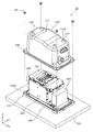
- FIG. 1 is a perspective view showing the appearance of the power storage device 10 according to the embodiment.
- FIG. 2 is an exploded perspective view showing the internal configuration of the power storage device 10 according to the embodiment.
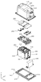
- FIG. 3 is an exploded perspective view showing a detailed internal configuration of the power storage device 10 according to the embodiment.
- the power cable 20 and the electric wire 30 shown in FIG. 1 are not shown.
- the power storage device 10 is a device that can charge electricity from the outside and discharge the electricity to the outside.
- the power storage device 10 is a battery module used for power storage, power supply, and the like.
- the power storage device 10 includes automobiles such as electric vehicles (EV), hybrid electric vehicles (HEV) or plug-in hybrid electric vehicles (PHEV), motorcycles, watercraft, snowmobiles, agricultural machinery, construction machinery and the like. It is used for driving a moving body, starting an engine or backing up, or for stationary use for home use or a generator.
- the power storage device 10 includes a power storage element unit 200 having a plurality of power storage elements 210, and a housing 100 for accommodating the power storage element units 200.
- the power storage element unit 200 has four power storage elements 210.
- the number of power storage elements 210 included in the power storage element unit 200 is not limited to four.
- the power storage element unit 200 may include at least one power storage element 210.
- the housing 100 forms a space for accommodating the power storage element unit 200 and the like between the fixed wall portion 140 provided with the fixing portion 145 for fixing the power storage device 10 to the other member 500 and the fixed wall portion 140. It has a box-shaped main body 105 and the like. As shown in FIG. 3, the fixed wall portion 140 is provided with a plurality of screw holes 146 for fixing the power storage element unit 200. The end member 300 and the power storage element unit 200 are fixed to the upper surface of the fixed wall portion 140 by screwing each of the plurality of bolts 50 penetrating the end member 300, which will be described later, into the screw holes 146. Further, the main body 105 is arranged so as to surround the end member 300 and the power storage element unit 200.
- each element such as the power storage element unit 200 is arranged on the upper surface of the flat plate-shaped fixed wall portion 140 as a whole, and the main body portion 105 is arranged so as to cover these power storage element units 200 and the like from above and from the side. ..
- the fixing portion 145 of the fixing wall portion 140 is provided with a fixing opening 145a, and the fixing opening 106 is provided at the end of the main body portion 105.
- the bolt 40 inserted through the fixing opening 106 and the fixing opening 145a is screwed into the screw hole (or nut) of the other member 500. That is, the main body portion 105 and the fixed wall portion 140 are fastened together with the other member 500 by the bolt 40.
- four such fixing points of the housing 100 are provided, and the power storage device 10 is fixed to the other member 500 by these four fixing points.
- one wall portion (wall portion on the plus side in the X-axis direction) of the main body portion 105 is provided with an exhaust pipe 190 and an external connection portion 195 arranged above the exhaust pipe 190.
- the exhaust pipe 190 is a member for guiding the gas to the outside of the housing 100 when the gas is discharged from the gas discharge valves of one or more power storage elements 210 in the housing 100.
- the external connection unit 195 is a member that holds a pair of power cables 20 connected to the positive electrode and the negative electrode of the power storage element unit 200, and a plurality of electric wires 30 connected to a BMU (Battery Management Unit) 400 described later.
- BMU Battery Management Unit
- the pair of power cables 20 and the plurality of electric wires 30 extend to the outside from the external connection portion 195, but each of the pair of power cables 20 and the plurality of electric wires 30 is located at the position of the external connection portion 195. , May have a connector for connecting to an external device.
- the power storage device 10 Since the housing 100 is made of a metal such as iron and has a box-shaped main body 105, the power storage device 10 is relatively small and has an outer shell (that is, the housing 100). It has the characteristic of high strength. Therefore, the power storage device 10 is mounted on the automobile as a battery for operating the electric device mounted on the automobile or as a backup battery for guaranteeing the operation. Therefore, as another member 500 to which the power storage device 10 is fixed, a part of the vehicle body of the automobile is exemplified. In FIGS. 1 and 2, the other member 500 is simply represented as a rectangular plate-shaped member, but the other member 500 has a size and shape as long as it has a portion to which the power storage device 10 can be fixed. Is not particularly limited.
- the housing 100 has a support wall portion 110 which is one of a plurality of wall portions other than the fixed wall portion 140, and the support wall portion 110 has an attachment portion 120 for attaching a supported member. are doing.
- a supported member larger than the support wall portion 110 can be attached to the mounting portion 120 when viewed from the opposite direction of the support wall portion 110 and the fixed wall portion 140.
- the mounting portion 120 has a mounting hole 120a that is screwed with a bolt or the like for mounting the supported member.
- the console box including the drink holder and the like can be attached to the four attachment portions 120 arranged on the support wall portion 110 in the present embodiment. That is, the power storage device 10 can function as a support member for supporting the console box.
- An arrangement example when the power storage device 10 is mounted on a vehicle, a positional relationship with a supported member, and the like will be described later with reference to FIGS. 4 to 8.
- a BMU (Battery Management Unit) 400 that controls charging / discharging of the power storage element unit 200 is further housed inside the housing 100.
- the BMU 400 is fixed to the upper surface of the fixing wall portion 140 with a plurality of bolts. It is not essential that the power storage device 10 incorporates the BMU 400, and the charge / discharge control of the power storage element unit 200 may be performed by an external device.
- the power storage element unit 200 is held in a state of being sandwiched between end members 300 facing each other in the arrangement direction (Y-axis direction) of the power storage elements 210.
- a plurality of bus bars 250 for electrically and mechanically connecting a plurality of power storage elements 210
- a bus bar frame 255 for holding the plurality of bus bars 250.
- the bus bar frame 255 is provided with a plurality of bus bar openings 256, each of the plurality of bus bars 250 being arranged in any of the plurality of bus bar openings 256, and one or two power storage elements below the bus bar frame 255. Joined to 210.
- the cover member 280 is further arranged above the power storage element unit 200, and the bus bar 250 is arranged between the power storage element unit 200 and the cover member 280. That is, the bus bar frame 255 is arranged between the power storage element unit 200 and the cover member 280.
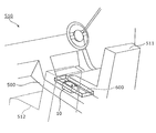
- FIG. 4 is a schematic view showing an arrangement example of the power storage device 10 according to the embodiment in the vehicle 510.
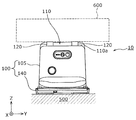
- FIG. 5 is a diagram showing an example of an attachment structure of the supported member 600 to the power storage device 10 according to the embodiment.
- FIG. 6 is a plan view showing a state in which the power storage device 10 according to the embodiment supports the supported member 600.
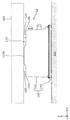
- FIG. 7 is a first side view of the power storage device 10 corresponding to FIG. 6, and
- FIG. 8 is a second side view of the power storage device 10 corresponding to FIG.
- FIG. 6 to 8 the approximate range of existence of the supported member 600 is shown by the range surrounded by the dotted line.
- a part of the vehicle body, which is another member 500 is simply shown as a rectangular plate-shaped member.
- FIG. 7 shows a side view of the power storage device 10 when viewed from the minus side in the Y-axis direction
- FIG. 8 shows a side view of the power storage device 10 when viewed from the plus side in the X-axis direction. There is.
- the power storage device 10 can be arranged between the seats arranged side by side in the vehicle 510 which is an ordinary automobile. In the example shown in FIG. 4, it is fixed to the portion between the driver's seat 511 and the passenger's seat 512 in the other member 500 which is the vehicle body of the vehicle 510.
- a supported member 600 is attached to the upper surface (support wall portion 110) of the power storage device 10.
- the supported member 600 is a console box having a drink holder or the like. That is, the console box, which is a member that needs to be arranged between the driver's seat 511 and the passenger's seat 512, is arranged as the supported member 600.
- the supported member 600 has a mounting plate 610 and an upper member 620 fixed to the mounting plate 610.
- the mounting plate 610 and the upper member 620 are connected by screws or the like (not shown).
- the mounting plate 610 is formed with the same number of through holes 611 as the mounting portion 120 of the power storage device 10.
- a bolt 70 is inserted into each through hole 611 and screwed into the mounting hole 120a, whereby the mounting plate 610 is fixed to the housing 100.
- the upper member 620 is fixed to the mounting plate 610.
- the supported member 600 is attached to the power storage device 10 and is supported by the power storage device 10.
- the relationship between the supported member 600 and the power storage device 10 in the top view is as shown in FIG. 6, that is, the supported member 600 is larger than the support wall portion 110 in the top view, and the housing 100. Is larger than the outer shape of.
- the supported member 600 does not need to be separated into the mounting plate 610 and the upper member 620, and the supported member 600, which is a single member, or the supported member 600 composed of a combination of three or more members It may be attached to the housing 100.
- the console box shown in FIG. 5 is illustrated as the supported member 600, but the type, shape, and size of the supported member 600 are not limited to this example.
- a floor plate, a frame fixed to the floor plate, and a decorative member such as a decorative plate may be adopted as the supported member 600.
- the power storage device 10 includes a housing 100.
- the housing 100 has a fixed wall portion 140 and a mounting portion 120 for mounting the supported member 600.
- the fixed wall portion 140 is a wall portion provided with a fixing portion 145 for fixing the housing 100 to another member 500.
- the mounting portion 120 is arranged on the support wall portion 110, which is one of a plurality of wall portions other than the fixed wall portion 140 of the housing 100.
- the supported member 600 is a member larger than the support wall portion 110 when the housing 100 is viewed from the direction in which the support wall portion 110 and the fixed wall portion 140 face each other.
- the mounting portion 120 is provided on the supporting wall portion 110 in a posture in which the supported member 600 mounted on the mounting portion 120 is positioned on the opposite side of the housing 100 from the other members 500.
- the housing 100 of the power storage device 10 fixed to the other member 500 can be used to support the supported member 600 arranged on the opposite side of the housing 100 from the other member 500. .. Therefore, as described above, when the power storage device 10 is arranged in a relatively narrow space such as the interior of the vehicle 510, a supported member 600 such as a floor board, a decorative board, or a drink holder is attached to the housing 100. be able to. In other words, by arranging the power storage device 10 at a position where the supported member 600 should be supported, both the support of the supported member 600 and the storage of the power storage device 10 are realized. As described above, according to the power storage device 10 of this embodiment, it is possible to effectively utilize and arrange a relatively narrow space.
- the mounting portion 120 is arranged in the low wall portion 110a, which is a portion recessed from the other portion in the support wall portion 110.
- the support wall portion 110 has an upper wall portion 110b of the central portion and low wall portions 110a arranged on both sides of the upper wall portion 110b in the X-axis direction.
- the mounting portion 120 which is a female screw member, is fixed to the support wall portion 110 by welding or the like, the mounting portion 120 is attached to another portion of the support wall portion 110 (upper wall portion 110b). It can be arranged so as not to protrude more than (see FIG. 7). That is, even when the mounting portion 120 is provided so as to project with respect to the support wall portion 110, the mounting portion 120 can be prevented from protruding as a whole of the housing 100. It is also possible to manufacture different types of power storage devices 10 by arranging mounting portions 120 having different inner diameters of the mounting holes 120a in a plurality of housings 100 of the same type by welding or the like.
- the support wall portion 110 is arranged at a position facing the fixed wall portion 140 in the housing 100.
- the supported member 600 is opposed to the other member 500 with the housing 100 interposed therebetween. Can be located on the side.
- the support of the supported member 600 by the housing 100 is more stabilized.
- the practicality of the power storage device 10 as a structure for supporting the supported member 600 is improved.
- the fixed portion 145 and the mounting portion 120 are , It is arranged in the outer shape of the housing 100. That is, the fixing portion 145 and the mounting portion 120 are arranged within the outer shape of the housing 100 in a plan view.
- the housing 100 receives the pressing force from the other member 500 and the supported member 600, the pressing force can be received by the entire housing 100 which is a box-shaped structure. Therefore, the load bearing capacity is improved as compared with the case where the fixing portion 145 or the mounting portion 120 is provided on the bracket protruding from the outer shape of the housing 100 in a plan view. As a result, the practicality of the power storage device 10 as a structure for supporting the supported member 600 is improved.
- the lower side of the housing 100 is from the upper side when the housing 100 is viewed from the side in a posture in which the fixed wall portion 140 faces downward. Is also formed in a long substantially trapezoidal shape.
- the side view shape of the housing 100 is a substantially trapezoidal shape in which the lower side is longer than the upper side, the supported member 600 located above the housing 100 can be stably supported. Since the load received by the support wall portion 110 from the supported member 600 is received by the fixed wall portion 140 having a relatively large area, an excessive pressure is applied to the other member 500 to which the fixed wall portion 140 is fixed from the power storage device 10. Is reduced. That is, the power storage device 10 arranged in a relatively narrow space can be used to stably support the supported member 600 having a relatively large weight. As a result, the practicality of the power storage device 10 as a structure for supporting the supported member 600 is improved.
- the mounting portion 120 is arranged at a corner of the support wall portion 110 when viewed from the opposite direction between the support wall portion 110 and the fixed wall portion 140.
- the mounting portion 120 is located near the position where the plurality of wall portions (support wall portion 110 and two side wall portions adjacent to each other) facing in different directions are connected. Is placed.
- the support wall portion 110 is a portion forming the top surface of the main body portion 105 formed in a box shape, and is integrally formed with the four side wall portions. Therefore, the corner portion of the support wall portion 110 is a high-strength portion in the housing 100. As described above, since the mounting portion 120 is arranged in the high-strength portion of the housing 100, the supported member 600 having a relatively large weight can be stably supported.
- the support wall portion 110 has four corners, and a mounting portion 120 is arranged at each of the four corners. This is advantageous for stable support of the supported member 600, which is larger than the support wall portion 110 in a plan view.
- the mounting portion 120 may be provided on the supporting wall portion 110 in a posture in which the supported member 600 mounted on the mounting portion 120 is positioned on the opposite side of the housing 100 from the other members 500. Therefore, the mounting portion may be provided so as to project laterally (direction parallel to the XY plane) from the support wall portion 110. It is assumed that the through hole of the bolt 70 (see FIG. 5) in the supported member 600 cannot be arranged within the outer shape of the support wall portion 110 in a plan view. In this case, it is possible to attach the supported member 600 to the housing 100 by using the attachment portion 120 provided so as to project laterally from the support wall portion 110.
- the support wall portion 110 does not need to be arranged at a position facing the fixed wall portion 140.
- One of the four side wall portions facing the X-axis direction or the Y-axis direction in the main body portion 105 of the housing 100 may function as a support wall portion.
- a mounting portion that protrudes above the upper surface of the housing 100 is arranged on the side wall portion that is the support wall portion.
- the number of mounting portions 120 is not limited to 4, and the housing 100 may have at least one mounting portion 120.
- the power storage device 10 capable of supplying electric power to an external device as a member for supporting the supported member 600.
- the side view shape of the housing 100 does not have to be substantially trapezoidal.
- the housing 100 may have an overall curved dome shape.
- the housing 100 may have a cylindrical shape in which the side surfaces form a series of curved surfaces.
- the housing 100 may have a wall portion having one or more openings formed when it is not necessary to seal the internal space. That is, any structure having a space for accommodating the power storage element unit 200 or the like and having a shape in which the fixing portion and the mounting portion can be arranged can be adopted as the housing 100.
- the material of the component of the power storage device 10 is not limited to the material described in the embodiment.
- the housing 100 does not have to be made of metal.
- the housing 100 may be formed of a non-metal such as fiber reinforced plastic.
- the materials of the main body 105 and the fixed wall 140 constituting the housing 100 may be different.
- the materials of the main body 105 and the fixed wall 140 may be determined based on the strength, rigidity, manufacturing cost, and the like required for the main body 105 and the fixed wall 140, respectively.
- the present invention can be applied to a power storage device provided with a power storage element such as a lithium ion secondary battery.
- Power storage device 100 Housing 110 Support wall part 120 Mounting part 140 Fixed wall part 145 Fixed part 200 Power storage element unit 500 Other members 600 Supported members
Abstract
蓄電装置(10)は、筐体(100)を備える。筐体(100)は、固定壁部(140)と、被支持部材(600)を取り付けるための取付部(120)とを有する。固定壁部(140)は、筐体(100)を他の部材(500)に固定するための固定部(145)が設けられた壁部である。取付部(120)は、筐体(100)の固定壁部(140)以外の複数の壁部の1つである支持壁部(110)に配置されている。被支持部材(600)は、支持壁部(110)と固定壁部(140)との対向方向から筐体(100)を見た場合に、支持壁部(110)よりも大きな部材である。取付部(120)は、取付部(120)に取り付けられた被支持部材(600)を、筐体(100)を挟んで他の部材(500)と反対側に位置させる姿勢で、支持壁部(110)に設けられている。
Description
本発明は、複数の蓄電素子を備える蓄電装置に関する。
特許文献1には、複数の単電池を備える蓄電装置が開示されている。この蓄電装置には、蓄電装置を車両ボディに対して位置決めする位置決め機構が設けられている。位置決め機構は、蓄電装置および車両ボディの一方に設けられたピンと、蓄電装置および車両ボディの他方に設けられ、ピンが挿入される溝に向かってピンをガイドするガイド部材と、を有する。特許文献1には、ガイド部材を用いることでピンを溝に容易に挿入することができ、車両ボディに対して蓄電装置を容易に位置決めできる旨が記載されている。
蓄電装置を搭載する機器では、内部空間の有効利用の観点から、蓄電装置の配置位置については制約がある。普通自動車では、室内空間の広さ、及び、収納空間の広さが求められるため、エンジンルームの外に蓄電装置を配置する場合に、蓄電装置をどのように配置すべきかが問題となる。この点に関し、特許文献1には、車両ボディの所定の位置に対して蓄電装置を容易に位置決めするための構造は開示されている。しかし、蓄電装置をどのような態様で配置することが、空間の有効利用につながるかは不明である。
本発明は、空間を有効利用して配置できる蓄電装置を提供することを目的とする。
本発明の一態様に係る蓄電装置は、筐体であって、前記筐体を他の部材に固定するための固定部が設けられた固定壁部を有する筐体と、前記筐体の前記固定壁部以外の複数の壁部の1つである支持壁部に配置された、被支持部材を取り付けるための取付部であって、前記支持壁部と前記固定壁部との対向方向から前記筐体を見た場合に、前記支持壁部よりも大きな前記被支持部材を取り付けるための取付部とを備え、前記取付部は、前記取付部に取り付けられた前記被支持部材を、前記筐体を挟んで前記他の部材と反対側に位置させる姿勢で、前記支持壁部に設けられている。
本発明によれば、空間を有効利用して配置できる蓄電装置を提供できる。
本発明の一態様に係る蓄電装置は、筐体であって、前記筐体を他の部材に固定するための固定部が設けられた固定壁部を有する筐体と、前記筐体の前記固定壁部以外の複数の壁部の1つである支持壁部に配置された、被支持部材を取り付けるための取付部であって、前記支持壁部と前記固定壁部との対向方向から前記筐体を見た場合に、前記支持壁部よりも大きな前記被支持部材を取り付けるための取付部とを備え、前記取付部は、前記取付部に取り付けられた前記被支持部材を、前記筐体を挟んで前記他の部材と反対側に位置させる姿勢で、前記支持壁部に設けられている。
この構成によれば、他の部材に固定された蓄電装置の筐体を利用して、筐体を挟んで他の部材と反対側に配置された被支持部材を支持できる。そのため、自動車の室内のような、比較的に狭い空間に蓄電装置を配置する場合に、その筐体に、床板、化粧板またはドリンクホルダ等の被支持部材を取り付けることができる。言い換えると、被支持部材が支持されるべき位置に蓄電装置を配置することで、被支持部材の支持と蓄電装置の収納との両方が実現される。このように、本態様の蓄電装置によれば、比較的に狭い空間を有効に利用して配置できる。
前記支持壁部は、前記筐体において前記固定壁部と対向する位置に配置されてもよい。
この構成によれば、取付部を、支持壁部の外面に設けることで、被支持部材を、筐体を挟んで他の部材と反対側に位置させることができる。この場合、筐体が被支持部材から受けた荷重が、筐体を回転させるモーメントとして作用し難いため、筐体による被支持部材の支持がより安定化される。これにより、蓄電装置の、被支持部材を支持する構造物としての実用性が向上する。
前記固定部及び前記取付部は、前記筐体を、前記支持壁部と前記固定壁部との対向方向から見た場合において、前記筐体の外形内に配置されてもよい。
この構成によれば、筐体が、他の部材及び被支持部材から押圧力を受けた場合に、箱型の構造物である筐体の全体で、その押圧力を受けることができる。従って、平面視における筐体の外形から突出するブラケットに固定部または取付部を設けた場合と比較すると、耐荷重性が向上する。これにより、蓄電装置の、被支持部材を支持する構造物としての実用性が向上する。
前記筐体は、前記固定壁部が下向きとなる姿勢にした状態で、前記筐体を側方から見た場合、下辺が上辺よりも長い略台形状に形成されてもよい。
この構成によれば、筐体が、固定壁部が下向きの姿勢である場合、筐体の側面視形状が、下辺が上辺より長い略台形状であるため、筐体の上方に位置する被支持部材を安定して支持できる。支持壁部が被支持部材から受ける荷重は、比較的に広い面積の固定壁部で受け止められるため、固定壁部が固定された他の部材に、蓄電装置から過大な圧力が付与される可能性が低減される。つまり、比較的に狭い空間に配置された蓄電装置を利用して、比較的に大きな重量の被支持部材を安定して支持できる。これにより、蓄電装置の、被支持部材を支持する構造物としての実用性が向上する。
前記取付部は、前記支持壁部と前記固定壁部との対向方向から見た場合における前記支持壁部の角部に配置されてもよい。
この構成によれば、筐体において、互いに異なる方向に向く複数の壁部(支持壁部を含む)が接続されている位置の近くに取付部が配置される。つまり、取付部は、筐体における強度の高い部分に配置されるため、比較的に大きな重量の被支持部材を安定して支持できる。これにより、蓄電装置の、被支持部材を支持する構造物としての実用性が向上する。
本発明は、複数の蓄電素子を含む蓄電素子ユニットを収容する筐体として実現できる。
以下、図面を参照しながら、本発明の実施の形態に係る蓄電装置について説明する。以下で説明する実施の形態は、包括的または具体的な例を示すものである。以下の実施の形態で示される数値、形状、材料、構成要素、構成要素の配置位置及び接続形態、製造工程、製造工程の順序などは、一例であり、本発明を限定する主旨ではない。以下の実施の形態における構成要素のうち、最上位概念を示す独立請求項に記載されていない構成要素については、任意の構成要素として説明される。各図において、寸法等は厳密に図示したものではない。
以下の説明及び図面中において、筐体の長手方向(筐体の短側面の対向方向)、または、1つの蓄電素子における短側面の対向方向をX軸方向と定義する。筐体の短手方向(筐体の長側面の対向方向)、または、1つの蓄電素子における長側面の対向方向をY軸方向と定義する。筐体における本体部と固定壁部との並び方向、または、蓄電素子の短側面の長手方向をZ軸方向と定義する。これらX軸方向、Y軸方向及びZ軸方向は、互いに交差(本実施の形態では直交)する方向である。本実施の形態では、Z軸方向を上下方向とし、かつ、Z軸方向プラス側を「上」として説明を行うが、このことは、実際の蓄電装置の使用時における姿勢を限定しない。各図面については、本発明を示すために、適宜強調、省略、または比率の調整を行うことで、実際の形状、位置関係、及び比率とは異なる場合がある。
X軸方向プラス側とは、X軸の矢印方向側を示し、X軸方向マイナス側とは、X軸方向プラス側とは反対側を示す。Y軸方向及びZ軸方向についても同様である。さらに、平行及び直交などの、相対的な方向または姿勢を示す表現は、厳密には、その方向または姿勢ではない場合も含む。2つの方向が直交している、とは、当該2つの方向が完全に直交していることを意味するだけでなく、実質的に直交していること、すなわち、数%程度の差異を含むことも意味する。
(実施の形態)
[1.蓄電装置の全般的な説明]
まず、図1~図3を用いて、実施の形態に係る蓄電装置10の全般的な説明を行う。図1は、実施の形態に係る蓄電装置10の外観を示す斜視図である。図2は、実施の形態に係る蓄電装置10の内部構成を示す分解斜視図である。図3は、実施の形態に係る蓄電装置10の詳細な内部構成を示す分解斜視図である。図2及び図3では、図1に示される電力ケーブル20及び電線30の図示は省略されている。
[1.蓄電装置の全般的な説明]
まず、図1~図3を用いて、実施の形態に係る蓄電装置10の全般的な説明を行う。図1は、実施の形態に係る蓄電装置10の外観を示す斜視図である。図2は、実施の形態に係る蓄電装置10の内部構成を示す分解斜視図である。図3は、実施の形態に係る蓄電装置10の詳細な内部構成を示す分解斜視図である。図2及び図3では、図1に示される電力ケーブル20及び電線30の図示は省略されている。
蓄電装置10は、外部からの電気を充電し、外部へ電気を放電できる装置である。蓄電装置10は、電力貯蔵用途または電源用途等に使用される電池モジュールである。具体的には、蓄電装置10は、電気自動車(EV)、ハイブリッド電気自動車(HEV)またはプラグインハイブリッド電気自動車(PHEV)等の自動車、自動二輪車、ウォータークラフト、スノーモービル、農業機械、建設機械等の移動体の駆動用、エンジン始動用若しくはバックアップ用、または、家庭用若しくは発電機用に使用される定置用として用いられる。
図1~図3に示すように、蓄電装置10は、複数の蓄電素子210を有する蓄電素子ユニット200と、蓄電素子ユニット200を収容する筐体100とを備える。本実施の形態では、蓄電素子ユニット200は4個の蓄電素子210を有している。蓄電素子ユニット200が有する蓄電素子210の数は4には限定されない。蓄電素子ユニット200は少なくとも1つの蓄電素子210を備えていればよい。
筐体100は、蓄電装置10を他の部材500に固定するための固定部145が設けられた固定壁部140と、固定壁部140との間に蓄電素子ユニット200等を収容する空間を形成する箱型の本体部105とを有する。図3に示すように、固定壁部140には、蓄電素子ユニット200の固定のためのねじ穴146が複数設けられている。後述するエンド部材300を貫通する複数のボルト50のそれぞれが、ねじ穴146に螺合することで、エンド部材300及び蓄電素子ユニット200が固定壁部140の上面に固定される。さらに、エンド部材300及び蓄電素子ユニット200を囲むように本体部105が配置される。
つまり、全体として平板状の固定壁部140の上面に蓄電素子ユニット200等の各要素が配置されており、これら蓄電素子ユニット200等を上方及び側方から覆うように本体部105が配置される。固定壁部140の固定部145には固定用開口部145aが設けられており、本体部105の端部には、固定用開口部106が設けられている。固定用開口部106及び固定用開口部145aに挿通されたボルト40が、他の部材500のねじ穴(またはナット)に螺合する。つまり、本体部105と固定壁部140とは、ボルト40によって他の部材500に共締めされる。本実施の形態では、このような、筐体100の固定箇所が4つ設けられており、これら4つの固定箇所によって、他の部材500に蓄電装置10が固定される。
図1に示すように、本体部105の一つの壁部(X軸方向プラス側の壁部)には、排気管190及び排気管190よりも上方に配置された外部接続部195が設けられている。排気管190は、筐体100内の1以上の蓄電素子210のガス排出弁からガスが排出された場合、そのガスを筐体100の外部に導くための部材である。外部接続部195は、蓄電素子ユニット200の正極及び負極に接続された一対の電力ケーブル20と、後述するBMU(Battery Management Unit)400に接続された複数の電線30とを保持する部材である。図1では、一対の電力ケーブル20及び複数の電線30は外部接続部195から外部に延設されているが、一対の電力ケーブル20及び複数の電線30のそれぞれは、外部接続部195の位置に、外部機器と接続するためのコネクタを有してもよい。
筐体100は、鉄等の金属で形成されており、かつ、箱型の本体部105を有しているため、蓄電装置10は、比較的に小型でかつ外殻(つまり筐体100)の強度が高いという特性を有している。そのため、蓄電装置10は、自動車に搭載された電気機器の動作のためのバッテリー、または、当該動作を保証するバックアップ用のバッテリーとして自動車に搭載される。従って、蓄電装置10が固定される他の部材500としては、自動車の車体の一部が例示される。図1及び図2では、他の部材500は、簡易的に矩形の板状部材として表しているが、他の部材500は、蓄電装置10を固定できる部分を有していれば、サイズ及び形状に特に限定はない。
筐体100は、固定壁部140以外の複数の壁部のうちの1つである支持壁部110を有しており、支持壁部110は、被支持部材を取り付けるための取付部120を有している。取付部120には、支持壁部110と固定壁部140との対向方向から見た場合に、支持壁部110よりも大きな被支持部材を取り付けることができる。取付部120は、被支持部材を取り付けるためのボルト等と螺合する取付穴120aを有している。蓄電装置10が自動車に搭載される場合、蓄電装置10は比較的に小型であることから、運転席と助手席との間に配置できる。この場合、本実施の形態において支持壁部110に4つ配置された取付部120に、ドリンクホルダ等を含むコンソールボックスを取り付けることができる。つまり、蓄電装置10を、コンソールボックスを支持する支持部材として機能させることができる。蓄電装置10を車両に搭載する場合の配置例、及び、被支持部材との位置関係等については、図4~図8を用いて後述する。
本実施の形態では、筐体100の内部にはさらに、蓄電素子ユニット200の充放電を制御するBMU(Battery Management Unit)400が収容されている。BMU400は、複数のボルトで固定壁部140の上面に固定される。蓄電装置10がBMU400を内蔵することは必須ではなく、蓄電素子ユニット200の充放電の制御は外部の機器によって行われてもよい。
蓄電素子ユニット200は、図2及び図3に示すように、蓄電素子210の並び方向(Y軸方向)で対向するエンド部材300に挟まれた状態で保持されている。蓄電素子ユニット200の電極端子の側(Z軸方向プラス側)には、複数の蓄電素子210を電気的及び機械的に接続する複数のバスバー250と、複数のバスバー250を保持するバスバーフレーム255とが配置される。バスバーフレーム255には、バスバー用開口部256が複数設けられており、複数のバスバー250のそれぞれは、複数のバスバー用開口部256のいずれかに配置され、その下方の1つまたは2つの蓄電素子210に接合される。
本実施の形態では、蓄電素子ユニット200の上方にはさらにカバー部材280が配置されており、蓄電素子ユニット200とカバー部材280との間にバスバー250が配置されている。つまり、蓄電素子ユニット200とカバー部材280との間にバスバーフレーム255が配置されている。
[2.蓄電装置の配置例及び利用例]
次に、以上のように構成された蓄電装置10を車両に搭載した場合の配置例及び被支持部材との位置関係等について、図4~図8を用いて説明する。図4は、実施の形態に係る蓄電装置10の車両510における配置例を示す模式図である。図5は、実施の形態に係る蓄電装置10への被支持部材600の取付構造の一例を示す図である。図6は、実施の形態に係る蓄電装置10が被支持部材600を支持している状態を示す平面図である。図7は、図6に対応する蓄電装置10の第1の側面図であり、図8は、図6に対応する蓄電装置10の第2の側面図である。図6~図8では、被支持部材600のおおよその存在範囲が点線で囲まれた範囲で示されている。図5では、他の部材500である車体の一部を簡易的に矩形の板状部材として図示している。図7では、Y軸方向マイナス側から見た場合の蓄電装置10の側面図が示されており、図8では、X軸方向プラス側から見た場合の蓄電装置10の側面図が示されている。
次に、以上のように構成された蓄電装置10を車両に搭載した場合の配置例及び被支持部材との位置関係等について、図4~図8を用いて説明する。図4は、実施の形態に係る蓄電装置10の車両510における配置例を示す模式図である。図5は、実施の形態に係る蓄電装置10への被支持部材600の取付構造の一例を示す図である。図6は、実施の形態に係る蓄電装置10が被支持部材600を支持している状態を示す平面図である。図7は、図6に対応する蓄電装置10の第1の側面図であり、図8は、図6に対応する蓄電装置10の第2の側面図である。図6~図8では、被支持部材600のおおよその存在範囲が点線で囲まれた範囲で示されている。図5では、他の部材500である車体の一部を簡易的に矩形の板状部材として図示している。図7では、Y軸方向マイナス側から見た場合の蓄電装置10の側面図が示されており、図8では、X軸方向プラス側から見た場合の蓄電装置10の側面図が示されている。
図4に示すように、蓄電装置10は、普通自動車である車両510において、並んで配置される座席の間に配置できる。図4に示す例では、車両510の車体である他の部材500における、運転席511と助手席512との間の部分に固定されている。蓄電装置10の上面(支持壁部110)には、被支持部材600が取り付けられている。被支持部材600は、図5に示すように、ドリンクホルダ等を有するコンソールボックスである。つまり、運転席511と助手席512との間への配置が必要な部材であるコンソールボックスが、被支持部材600として配置される。
被支持部材600は、取付板610と取付板610に固定される上部部材620とを有する。取付板610と上部部材620とは、図示しないネジ等で接続される。取付板610には、蓄電装置10が有する取付部120と同じ数の貫通孔611が形成されている。各貫通孔611にボルト70が挿入されて取付穴120aに螺合され、これにより、取付板610が筐体100に固定される。さらに、取付板610に上部部材620が固定される。これにより、被支持部材600が蓄電装置10に取り付けられ、かつ、蓄電装置10に支持された状態となる。このとき、上面視における被支持部材600と蓄電装置10との関係は、図6に示す状態となる、つまり、上面視において、被支持部材600は、支持壁部110よりも大きく、筐体100の外形よりも大きい。
被支持部材600は、取付板610と上部部材620とに分離される必要はなく、単一の部材である被支持部材600、または3以の部材の組み合わせで構成される被支持部材600が、筐体100に取り付けられてもよい。本実施の形態では、被支持部材600として、図5に示すコンソールボックスを例示しているが、被支持部材600の種類、形状、及び大きさはこの例示に限定されない。蓄電装置10が車両に搭載される場合、被支持部材600として、床板、床板に固定されたフレーム、及び化粧板などの装飾部材が採用されてもよい。
[3.効果等]
以上説明したように、本実施の形態に係る蓄電装置10は、筐体100を備える。筐体100は、固定壁部140と、被支持部材600を取り付けるための取付部120とを有する。固定壁部140は、筐体100を他の部材500に固定するための固定部145が設けられた壁部である。取付部120は、筐体100の固定壁部140以外の複数の壁部の1つである支持壁部110に配置されている。被支持部材600は、支持壁部110と固定壁部140との対向方向から筐体100を見た場合に、支持壁部110よりも大きな部材である。取付部120は、取付部120に取り付けられた被支持部材600を、筐体100を挟んで他の部材500と反対側に位置させる姿勢で、支持壁部110に設けられている。
以上説明したように、本実施の形態に係る蓄電装置10は、筐体100を備える。筐体100は、固定壁部140と、被支持部材600を取り付けるための取付部120とを有する。固定壁部140は、筐体100を他の部材500に固定するための固定部145が設けられた壁部である。取付部120は、筐体100の固定壁部140以外の複数の壁部の1つである支持壁部110に配置されている。被支持部材600は、支持壁部110と固定壁部140との対向方向から筐体100を見た場合に、支持壁部110よりも大きな部材である。取付部120は、取付部120に取り付けられた被支持部材600を、筐体100を挟んで他の部材500と反対側に位置させる姿勢で、支持壁部110に設けられている。
この構成によれば、他の部材500に固定された蓄電装置10の筐体100を利用して、筐体100を挟んで他の部材500と反対側に配置された被支持部材600を支持できる。そのため、上述のように、車両510の室内のような比較的に狭い空間に蓄電装置10を配置する場合に、その筐体100に、床板、化粧板またはドリンクホルダ等の被支持部材600を取り付けることができる。言い換えると、被支持部材600が支持されるべき位置に蓄電装置10を配置することで、被支持部材600の支持と蓄電装置10の収納との両方が実現される。このように、本態様の蓄電装置10によれば、比較的に狭い空間を有効に利用して配置できる。
本実施の形態では、図5~図8に示すように、取付部120は、支持壁部110において他の部分より凹んだ部分である低壁部110aに配置されている。具体的には、支持壁部110は、中央部分の上壁部110bと、上壁部110bのX軸方向の両側に配置された低壁部110aとを有する。
この構成によれば、雌ねじ部材である取付部120を、支持壁部110に溶接等で固定する場合であっても、取付部120を、支持壁部110の他の部分(上壁部110b)よりも突出させないように配置できる(図7参照)。つまり、取付部120が、支持壁部110に対して突出状に設けられている場合であっても、筐体100の全体として、取付部120が突出しない状態にできる。同じ種類の複数の筐体100に、取付穴120aの内径が互いに異なる取付部120を溶接等で配置することで、互いに種類が異なる蓄電装置10を製造することも可能である。
本実施の形態では、支持壁部110は、筐体100において固定壁部140と対向する位置に配置されている。
この構成によれば、図7及び図8に示すように、取付部120を、支持壁部110の外面に設けることで、被支持部材600を、筐体100を挟んで他の部材500と反対側に位置させることができる。この場合、筐体100が被支持部材600から受けた荷重が、筐体100を回転させるモーメントとして作用し難いため、筐体100による被支持部材600の支持がより安定化される。これにより、蓄電装置10の、被支持部材600を支持する構造物としての実用性が向上する。
本実施の形態では、図6に示すように、筐体100を、支持壁部110と固定壁部140との対向方向(Z軸方向)から見た場合において、固定部145及び取付部120は、筐体100の外形内に配置されている。つまり、固定部145及び取付部120は、平面視における筐体100の外形内に配置されている。
従って、筐体100が、他の部材500及び被支持部材600から押圧力を受けた場合に、箱型の構造物である筐体100の全体で、その押圧力を受けることができる。そのため、平面視における筐体100の外形から突出するブラケットに固定部145または取付部120を設けた場合と比較すると、耐荷重性が向上する。これにより、蓄電装置10の、被支持部材600を支持する構造物としての実用性が向上する。
本実施の形態では、図7及び図8に示すように、筐体100は、固定壁部140が下向きとなる姿勢にした状態で、筐体100を側方から見た場合、下辺が上辺よりも長い略台形状に形成されている。
つまり、筐体100の側面視形状が、下辺が上辺より長い略台形状であるため、筐体100の上方に位置する被支持部材600を安定して支持できる。支持壁部110が被支持部材600から受ける荷重は、比較的に広い面積の固定壁部140で受け止められるため、固定壁部140が固定された他の部材500に、蓄電装置10から過大な圧力が付与される可能性が低減される。つまり、比較的に狭い空間に配置された蓄電装置10を利用して、比較的に大きな重量の被支持部材600を安定して支持できる。これにより、蓄電装置10の、被支持部材600を支持する構造物としての実用性が向上する。
本実施の形態において、取付部120は、図6に示すように、支持壁部110と固定壁部140との対向方向から見た場合における支持壁部110の角部に配置されている。
このように、本実施の形態では、筐体100において、互いに異なる方向に向く複数の壁部(支持壁部110及び互いに隣接する2つの側壁部)が接続されている位置の近くに取付部120が配置される。本実施の形態では、支持壁部110は、箱型に形成された本体部105の天面を形成する部分であり、4つの側壁部と一体に形成されている。従って、支持壁部110の角部は筐体100における強度の高い部分である。このように、取付部120は、筐体100における強度の高い部分に配置されるため、比較的に大きな重量の被支持部材600を安定して支持できる。これにより、蓄電装置10の、被支持部材600を支持する構造物としての実用性が向上する。本実施の形態では、支持壁部110には4つの角部が存在し、これら4つの角部のそれぞれに取付部120が配置されている。このことは、平面視において支持壁部110より大きな被支持部材600の安定的な支持に有利である。
(他の実施の形態)
以上、本発明に係る蓄電装置について、実施の形態に基づいて説明した。しかしながら、本発明は、上記実施の形態に限定されるものではない。本発明の趣旨を逸脱しない限り、当業者が思いつく各種変形を上記実施の形態に施したものも、あるいは、上記説明された複数の構成要素を組み合わせて構築される形態も、本発明の範囲内に含まれる。
以上、本発明に係る蓄電装置について、実施の形態に基づいて説明した。しかしながら、本発明は、上記実施の形態に限定されるものではない。本発明の趣旨を逸脱しない限り、当業者が思いつく各種変形を上記実施の形態に施したものも、あるいは、上記説明された複数の構成要素を組み合わせて構築される形態も、本発明の範囲内に含まれる。
取付部120は、取付部120に取り付けられた被支持部材600を、筐体100を挟んで他の部材500と反対側に位置させる姿勢で、支持壁部110に設けられていればよい。そのため、取付部は、支持壁部110から側方(XY平面に平行な方向)に突出して設けられていてもよい。被支持部材600における、ボルト70(図5参照)の貫通孔を、平面視における支持壁部110の外形内に配置できない場合を想定する。この場合、支持壁部110から側方に突出して設けられた取付部120を用いて、被支持部材600を筐体100に取り付けることは可能である。
支持壁部110は、固定壁部140と対向する位置に配置されている必要はない。筐体100の本体部105における、X軸方向またはY軸方向に向く4つの側壁部のうちの一つが、支持壁部として機能してもよい。この場合、支持壁部である側壁部に、筐体100の上面よりも上方に突出する取付部を配置する。これにより、被支持部材600を、筐体100を挟んで他の部材500と反対側に位置させる姿勢で、筐体100に支持させることは可能である。
取付部120の個数は4には限定されず、筐体100は、少なくとも1つの取付部120を有すればよい。固定部145についても同様であり、筐体100は、少なくとも1つの固定部145を有すればよい。いずれの場合であっても、外部の機器に電力を供給できる蓄電装置10を、被支持部材600を支持するための部材として利用することは可能である。
筐体100の側面視形状は略台形である必要はない。筐体100は、全体的に湾曲したドーム状の形状でもよい。筐体100は、側面が一連の湾曲面を形成する円筒状の形状でもよい。筐体100は、内部空間を封止する必要がない場合、1以上の開口部が形成された壁部を有してもよい。つまり、内部に蓄電素子ユニット200等を収容する空間を有し、かつ、固定部及び取付部が配置可能な形状を有する構造物であれば、筐体100として採用することは可能である。
蓄電装置10の構成要素の素材は、実施の形態で説明された素材には限定されない。筐体100は金属製でなくてもよい。繊維強化プラスチックのような非金属によって筐体100が形成されてもよい。筐体100を構成する本体部105及び固定壁部140のそれぞれの素材が異なっていてもよい。本体部105及び固定壁部140のそれぞれに求められる強度、剛性、または製造コスト等に基づいて、本体部105及び固定壁部140のそれぞれの素材が決定されてもよい。
上記実施の形態に含まれる構成要素を任意に組み合わせて構築される形態も、本発明の範囲内に含まれる。
本発明は、リチウムイオン二次電池などの蓄電素子を備えた蓄電装置に適用できる。
10 蓄電装置
100 筐体
110 支持壁部
120 取付部
140 固定壁部
145 固定部
200 蓄電素子ユニット
500 他の部材
600 被支持部材
100 筐体
110 支持壁部
120 取付部
140 固定壁部
145 固定部
200 蓄電素子ユニット
500 他の部材
600 被支持部材
Claims (5)
- 筐体であって、前記筐体を他の部材に固定するための固定部が設けられた固定壁部を有する筐体と、
前記筐体の前記固定壁部以外の複数の壁部の1つである支持壁部に配置された、被支持部材を取り付けるための取付部であって、前記支持壁部と前記固定壁部との対向方向から前記筐体を見た場合に、前記支持壁部よりも大きな前記被支持部材を取り付けるための取付部とを備え、
前記取付部は、前記取付部に取り付けられた前記被支持部材を、前記筐体を挟んで前記他の部材と反対側に位置させる姿勢で、前記支持壁部に設けられている、
蓄電装置。 - 前記支持壁部は、前記筐体において前記固定壁部と対向する位置に配置されている、
請求項1記載の蓄電装置。 - 前記筐体を、前記支持壁部と前記固定壁部との対向方向から見た場合において、前記固定部及び前記取付部は、前記筐体の外形内に配置されている、
請求項2記載の蓄電装置。 - 前記筐体は、前記固定壁部が下向きとなる姿勢にした状態で、前記筐体を側方から見た場合、下辺が上辺よりも長い略台形状に形成されている、
請求項1~3のいずれか一項に記載の蓄電装置。 - 前記取付部は、前記支持壁部と前記固定壁部との対向方向から見た場合における前記支持壁部の角部に配置されている、
請求項1~4のいずれか一項に記載の蓄電装置。
Priority Applications (1)
| Application Number | Priority Date | Filing Date | Title |
|---|---|---|---|
| JP2021507355A JPWO2020189658A1 (ja) | 2019-03-18 | 2020-03-17 |
Applications Claiming Priority (2)
| Application Number | Priority Date | Filing Date | Title |
|---|---|---|---|
| JP2019-050050 | 2019-03-18 | ||
| JP2019050050 | 2019-03-18 |
Publications (1)
| Publication Number | Publication Date |
|---|---|
| WO2020189658A1 true WO2020189658A1 (ja) | 2020-09-24 |
Family
ID=72520872
Family Applications (1)
| Application Number | Title | Priority Date | Filing Date |
|---|---|---|---|
| PCT/JP2020/011624 WO2020189658A1 (ja) | 2019-03-18 | 2020-03-17 | 蓄電装置 |
Country Status (2)
| Country | Link |
|---|---|
| JP (1) | JPWO2020189658A1 (ja) |
| WO (1) | WO2020189658A1 (ja) |
Citations (6)
| Publication number | Priority date | Publication date | Assignee | Title |
|---|---|---|---|---|
| JPS4031872Y1 (ja) * | 1964-09-01 | 1965-11-09 | ||
| JPS57154506U (ja) * | 1981-03-24 | 1982-09-28 | ||
| JPS6319755A (ja) * | 1986-07-11 | 1988-01-27 | Nec Corp | シ−ル形据置蓄電池の床下設置方式 |
| JPH01158655U (ja) * | 1988-04-21 | 1989-11-01 | ||
| JP2009137417A (ja) * | 2007-12-06 | 2009-06-25 | Toyota Motor Corp | 車両用ドリンクウォーマ |
| JP2017196958A (ja) * | 2016-04-26 | 2017-11-02 | トヨタ自動車株式会社 | 車両のバッテリ搭載構造 |
-
2020
- 2020-03-17 JP JP2021507355A patent/JPWO2020189658A1/ja active Pending
- 2020-03-17 WO PCT/JP2020/011624 patent/WO2020189658A1/ja active Application Filing
Patent Citations (6)
| Publication number | Priority date | Publication date | Assignee | Title |
|---|---|---|---|---|
| JPS4031872Y1 (ja) * | 1964-09-01 | 1965-11-09 | ||
| JPS57154506U (ja) * | 1981-03-24 | 1982-09-28 | ||
| JPS6319755A (ja) * | 1986-07-11 | 1988-01-27 | Nec Corp | シ−ル形据置蓄電池の床下設置方式 |
| JPH01158655U (ja) * | 1988-04-21 | 1989-11-01 | ||
| JP2009137417A (ja) * | 2007-12-06 | 2009-06-25 | Toyota Motor Corp | 車両用ドリンクウォーマ |
| JP2017196958A (ja) * | 2016-04-26 | 2017-11-02 | トヨタ自動車株式会社 | 車両のバッテリ搭載構造 |
Also Published As
| Publication number | Publication date |
|---|---|
| JPWO2020189658A1 (ja) | 2020-09-24 |
Similar Documents
| Publication | Publication Date | Title |
|---|---|---|
| CN106104854B (zh) | 母线模块、蓄电池监视模块及蓄电池模块 | |
| US10090495B2 (en) | Electricity storage device | |
| US7508164B2 (en) | Battery pack having control devices of differing heights | |
| CN106797005B (zh) | 车载电源装置 | |
| JP2007069801A (ja) | 電源装置の車両搭載構造 | |
| JP5421836B2 (ja) | 電源装置 | |
| CN103427050A (zh) | 电源装置 | |
| JP2023504557A (ja) | バッテリーパック及びそれを含む自動車 | |
| JP6808283B2 (ja) | 組電池 | |
| JPWO2017179650A1 (ja) | 蓄電装置 | |
| WO2018143079A1 (ja) | 組電池 | |
| JP6307144B1 (ja) | 組電池 | |
| WO2020189658A1 (ja) | 蓄電装置 | |
| CN216942970U (zh) | 控制盒、电池及用电装置 | |
| US20230028117A1 (en) | Battery wiring module | |
| JP6285003B1 (ja) | 組電池 | |
| JP6884570B2 (ja) | 組電池 | |
| CN116137366A (zh) | 电池模组 | |
| JP7447428B2 (ja) | 蓄電装置 | |
| KR20190101263A (ko) | 배터리 팩의 외함, 이를 이용한 배터리 팩 및 자동차 | |
| JP2018101496A (ja) | 組電池 | |
| JP2010257944A (ja) | モジュール用端子 | |
| WO2014175108A1 (ja) | 燃料電池ユニット | |
| JP7392268B2 (ja) | 蓄電装置取付台 | |
| WO2020189657A1 (ja) | 蓄電装置 |
Legal Events
| Date | Code | Title | Description |
|---|---|---|---|
| 121 | Ep: the epo has been informed by wipo that ep was designated in this application |
Ref document number: 20774463 Country of ref document: EP Kind code of ref document: A1 |
|
| ENP | Entry into the national phase |
Ref document number: 2021507355 Country of ref document: JP Kind code of ref document: A |
|
| NENP | Non-entry into the national phase |
Ref country code: DE |
|
| 122 | Ep: pct application non-entry in european phase |
Ref document number: 20774463 Country of ref document: EP Kind code of ref document: A1 |