WO2020189404A1 - 監視システム - Google Patents
監視システム Download PDFInfo
- Publication number
- WO2020189404A1 WO2020189404A1 PCT/JP2020/010251 JP2020010251W WO2020189404A1 WO 2020189404 A1 WO2020189404 A1 WO 2020189404A1 JP 2020010251 W JP2020010251 W JP 2020010251W WO 2020189404 A1 WO2020189404 A1 WO 2020189404A1
- Authority
- WO
- WIPO (PCT)
- Prior art keywords
- monitoring
- communication
- unit
- terminal
- response
- Prior art date
- Legal status (The legal status is an assumption and is not a legal conclusion. Google has not performed a legal analysis and makes no representation as to the accuracy of the status listed.)
- Ceased
Links
Images






Classifications
-
- H—ELECTRICITY
- H04—ELECTRIC COMMUNICATION TECHNIQUE
- H04L—TRANSMISSION OF DIGITAL INFORMATION, e.g. TELEGRAPHIC COMMUNICATION
- H04L43/00—Arrangements for monitoring or testing data switching networks
- H04L43/08—Monitoring or testing based on specific metrics, e.g. QoS, energy consumption or environmental parameters
- H04L43/0805—Monitoring or testing based on specific metrics, e.g. QoS, energy consumption or environmental parameters by checking availability
- H04L43/0817—Monitoring or testing based on specific metrics, e.g. QoS, energy consumption or environmental parameters by checking availability by checking functioning
-
- G—PHYSICS
- G06—COMPUTING OR CALCULATING; COUNTING
- G06F—ELECTRIC DIGITAL DATA PROCESSING
- G06F11/00—Error detection; Error correction; Monitoring
- G06F11/30—Monitoring
- G06F11/3055—Monitoring arrangements for monitoring the status of the computing system or of the computing system component, e.g. monitoring if the computing system is on, off, available, not available
-
- G—PHYSICS
- G06—COMPUTING OR CALCULATING; COUNTING
- G06F—ELECTRIC DIGITAL DATA PROCESSING
- G06F13/00—Interconnection of, or transfer of information or other signals between, memories, input/output devices or central processing units
-
- H—ELECTRICITY
- H04—ELECTRIC COMMUNICATION TECHNIQUE
- H04L—TRANSMISSION OF DIGITAL INFORMATION, e.g. TELEGRAPHIC COMMUNICATION
- H04L41/00—Arrangements for maintenance, administration or management of data switching networks, e.g. of packet switching networks
- H04L41/08—Configuration management of networks or network elements
- H04L41/0893—Assignment of logical groups to network elements
-
- H—ELECTRICITY
- H04—ELECTRIC COMMUNICATION TECHNIQUE
- H04L—TRANSMISSION OF DIGITAL INFORMATION, e.g. TELEGRAPHIC COMMUNICATION
- H04L43/00—Arrangements for monitoring or testing data switching networks
- H04L43/06—Generation of reports
- H04L43/065—Generation of reports related to network devices
-
- H—ELECTRICITY
- H04—ELECTRIC COMMUNICATION TECHNIQUE
- H04W—WIRELESS COMMUNICATION NETWORKS
- H04W24/00—Supervisory, monitoring or testing arrangements
- H04W24/02—Arrangements for optimising operational condition
-
- H—ELECTRICITY
- H04—ELECTRIC COMMUNICATION TECHNIQUE
- H04L—TRANSMISSION OF DIGITAL INFORMATION, e.g. TELEGRAPHIC COMMUNICATION
- H04L41/00—Arrangements for maintenance, administration or management of data switching networks, e.g. of packet switching networks
- H04L41/04—Network management architectures or arrangements
- H04L41/046—Network management architectures or arrangements comprising network management agents or mobile agents therefor
-
- H—ELECTRICITY
- H04—ELECTRIC COMMUNICATION TECHNIQUE
- H04L—TRANSMISSION OF DIGITAL INFORMATION, e.g. TELEGRAPHIC COMMUNICATION
- H04L43/00—Arrangements for monitoring or testing data switching networks
- H04L43/08—Monitoring or testing based on specific metrics, e.g. QoS, energy consumption or environmental parameters
- H04L43/0823—Errors, e.g. transmission errors
- H04L43/0829—Packet loss
-
- H—ELECTRICITY
- H04—ELECTRIC COMMUNICATION TECHNIQUE
- H04L—TRANSMISSION OF DIGITAL INFORMATION, e.g. TELEGRAPHIC COMMUNICATION
- H04L43/00—Arrangements for monitoring or testing data switching networks
- H04L43/08—Monitoring or testing based on specific metrics, e.g. QoS, energy consumption or environmental parameters
- H04L43/0876—Network utilisation, e.g. volume of load or congestion level
Definitions
- the present invention relates to a monitoring system.
- Non-Patent Document 1 SNMP (Simple Network Management Protocol) has been used to monitor communication infrastructure (see Non-Patent Document 1).
- the monitoring device performs status monitoring by constantly acquiring status information from the device to be monitored.
- Such monitoring using SNMP is also used in IoT (Internet of Things) devices such as sensors.
- LPWA Low Power Wide Area
- Many terminals that use LPWA are battery-powered, and the battery capacity is extremely small. Therefore, when responding to the steady monitoring communication by the monitoring using SNMP, the battery life of the terminal using LPWA is remarkably deteriorated. Therefore, when monitoring the state of a terminal that uses LPWA, it is required to suppress the power consumption of the terminal that communicates with low power. It should be noted that such a problem occurs not only in monitoring using SNMP but also in monitoring using other monitoring communication protocols.
- an object of the present invention is to provide a technique capable of suppressing the power consumption of a terminal that communicates with low power.
- One aspect of the present invention is a monitoring system including a monitoring agent that holds information about a communication state of a low power terminal that communicates with low power and a monitoring device that monitors the state of the low power terminal.
- the device includes a requesting unit that requests information on the communication status of the low power terminal, and the monitoring agent responds to a request from the monitoring device based on the information on the communication status of the low power terminal.
- It is a monitoring system including a response generation unit for generating and a transmission unit for transmitting the response to the monitoring device.
- One aspect of the present invention is the above-mentioned monitoring system, in which the monitoring agent groups a plurality of the low-power terminals with one address information, and the response generation unit requests from the monitoring device in units of groups. Generate a response according to.
- the monitoring device further includes a state determination unit that determines the state of the low power terminal based on the information included in the response, and the state determination unit. Performs any or all of congestion determination, communication quality estimation, and failure determination as status monitoring of the low power terminal based on the information included in the response.
- One aspect of the present invention is the above-mentioned monitoring system, and based on the result of the state monitoring, the setting control of the relay device to which the low-power terminal is connected, the network design control, and the setting control of the low-power terminal. It further includes a setting design control unit that performs any or all of them.
- One aspect of the present invention is the above-mentioned monitoring system, in which the state determination unit calculates a resource utilization rate and another system interference amount based on the traffic amount in the group and the interference time rate of other systems, and within the group.
- the communication quality in the group is estimated based on the communication frequency and the received signal strength, and the failure location in the group is estimated based on the communication frequency and the packet loss rate.
- One aspect of the present invention is the above-mentioned monitoring system, in which the setting design control unit sets a channel or transmits and outputs in the relay device according to a resource utilization rate, communication quality, an amount of interference with other systems, or a failure location. , The communication path in the group including the relay device and the low power terminal, or the setting of the low power terminal is controlled.
- One aspect of the present invention is the above-mentioned monitoring system, in which the setting design control unit relays so as to level the communication load based on any of the resource utilization rate, the communication quality, and the interference amount of other systems.
- the number of devices is increased or decreased, or the arrangement of the relay device is changed as the network design control.
- FIG. 1 is a configuration diagram showing a system configuration of the monitoring system 100 in the present invention.
- the monitoring system 100 includes an LPWA terminal 10, a relay device 20, a monitoring agent 30, a monitoring device 40, and a user server 50.
- the monitoring system 100 may include two or more LPWA terminals 10 and a relay device 20.
- the LPWA terminal 10 is driven by a battery and communicates with the relay device 20 using LPWA.
- the LPWA terminal 10 is, for example, a sensor that measures the environment.
- the environment is, for example, temperature, humidity, amount of water, and the like.
- the LPWA terminal 10 periodically (for example, every 10 minutes, every hour) transmits the measurement result to the relay device 20.
- the measurement result includes the terminal ID, the terminal address, and the measured value.
- the LPWA terminal 10 is not limited to the sensor, and may be any terminal as long as it uses LPWA and is battery-powered.
- any of LoRa (registered trademark), SIGFOX (registered trademark), and NB-IoT (Narrow Band IoT) may be used.
- the relay device 20 keeps a record of data communication with the LPWA terminal 10 connected to its own device, and periodically transmits it to the monitoring agent 30.
- the data communication record includes a terminal ID, a terminal address, a communication recording time, a received signal strength (radio wave strength), a radio channel, a payload size, and the like. Further, the relay device 20 transmits the information transmitted from the user server 50 to the LPWA terminal 10. Further, the relay device 20 changes the setting of its own device based on the information transmitted from the monitoring device 40.
- the monitoring agent 30 keeps a record of data communication transmitted from the relay device 20.
- the monitoring agent 30 creates a response in response to the monitoring request transmitted from the monitoring device 40, and transmits the created response to the monitoring device 40.
- the monitoring agent 30 transmits information on the communication status of the LPWA terminal 10 to the monitoring device 40 as a response on behalf of the LPWA terminal 10.
- the monitoring agent 30 is configured by using an information processing device such as a notebook computer, a personal computer, a smartphone, a mobile phone, a tablet terminal, or a game device.
- the monitoring device 40 implements a monitoring communication protocol (for example, SNMP) and requests the monitoring agent 30 to transmit a data communication record.
- the monitoring device 40 monitors the status of the LPWA terminal 10 and the relay device 20 based on the obtained data communication record.
- the condition monitoring is, for example, congestion determination, communication quality estimation, and failure determination.
- the monitoring device 40 performs setting control of the relay device 20, network design control, and setting control of the LPWA terminal 10 based on the result of the state monitoring.
- the monitoring device 40 is configured by using an information processing device such as a notebook computer, a personal computer, a smartphone, a mobile phone, a tablet terminal, or a game device.
- the monitoring device 40 monitors the status of the LPWA terminal 10 and the relay device 20 belonging to the group on a group-by-group basis.
- the unit of the group does not have to be particularly limited. For example, it may be composed of LPWA terminals 10 connected to the same relay device 20, or a group of a plurality of relay devices 20 may belong to one group. In the following description, a case where status monitoring is performed in a group unit composed of LPWA terminals 10 connected to the same relay device 20 will be described as an example.
- Each group is identified to the monitoring agent 30 by an IP address assigned to identify the group.
- the user server 50 controls the setting of the LPWA terminal 10 via the relay device 20 in response to an instruction from the monitoring device 40.
- the user server 50 is configured by using an information processing device such as a notebook computer, a personal computer, a smartphone, a mobile phone, a tablet terminal, or a game device.
- FIG. 2 is a schematic block diagram showing a functional configuration of the monitoring agent 30 in the embodiment.
- the monitoring agent 30 includes a CPU (Central Processing Unit), a memory, an auxiliary storage device, and the like connected by a bus, and executes a monitoring program. By executing the monitoring program, the monitoring agent 30 functions as a device including a first communication unit 31, a control unit 32, a storage unit 33, and a second communication unit 34. All or part of each function of the monitoring agent 30 may be realized by using hardware such as an ASIC (Application Specific Integrated Circuit), a PLD (Programmable Logic Device), or an FPGA (Field Programmable Gate Array).
- the monitoring program may also be recorded on a computer-readable recording medium.
- the computer-readable recording medium is, for example, a flexible disk, a magneto-optical disk, a portable medium such as a ROM or a CD-ROM, or a storage device such as a hard disk built in a computer system. Further, the monitoring program may be transmitted and received via a telecommunication line.
- the first communication unit 31 communicates with the relay device 20.
- the first communication unit 31 receives the data communication record from the relay device 20.
- the control unit 32 is configured by using a processor such as a CPU and a memory.
- the control unit 32 functions as a data recording unit 321 and a response generation unit 322.
- the data recording unit 321 associates a predetermined IP address corresponding to the terminal ID with the data communication record received by the first communication unit 31 and records it in the storage unit 33.
- a predetermined IP address is associated with each terminal ID in advance. For example, the same IP address is associated with the terminal ID of the LPWA terminal 10 belonging to one group. This makes it possible to manage information on a group basis.
- the response generation unit 322 generates a response in response to the monitoring request transmitted from the monitoring agent 30.
- the storage unit 33 stores the association database 331, the communication record database 332, and the analysis table 333.
- the storage unit 33 is configured by using a storage device such as a magnetic hard disk device or a semiconductor storage device.
- the association database 331 has the configuration shown in FIG. 3, and is a database in which a terminal ID and an IP address are registered in association with each other.
- FIG. 3 is a diagram showing an example of the association database 331.
- the association database 331 has a plurality of records representing information regarding the association between the terminal ID and the IP address.
- the record has each value of the terminal ID and the IP address.
- the terminal ID represents identification information for identifying the LPWA terminal 10.
- the IP address represents an IP address to be associated with the terminal ID.
- the IP address is an IP address assigned to the monitoring agent 30.
- a plurality of terminal IDs are registered in the correspondence database 331. These terminal IDs are "ED-1" and "ED-2".
- the record registered in the uppermost stage of the association database 331 has a terminal ID value of “ED-1” and an IP address value of “vvv”. That is, it is shown that the IP address "vvv" is associated with the data communication record relating to the LPWA terminal 10 identified by the terminal ID "ED-1".
- the communication record database 332 has the configuration shown in FIG. 4, and is a database in which information related to data communication records is registered.
- FIG. 4 is a diagram showing an example of the communication record database 332.
- the communication record database 332 has a plurality of records representing information regarding data communication records.
- the record has values of terminal ID, IP address, communication recording time, received signal strength, radio channel and payload size.
- the terminal ID represents identification information for identifying the LPWA terminal 10.
- the IP address represents an IP address to be associated with the terminal ID.
- the communication recording time represents the time when the measurement result is received by the relay device 20.
- the received signal strength represents the signal strength when the measurement result is received by the relay device 20.
- the wireless channel represents a channel when the measurement result is received by the relay device 20.
- the payload size represents the size of the payload of the measurement result received by the relay device 20.
- a plurality of terminal IDs are registered in the communication record database 332. These terminal IDs are "ED-1” and "ED-2".
- the records registered in the uppermost stage of the communication record database 332 have a terminal ID value of "ED-1”, an IP address value of "vvv”, a communication recording time value of "YYMMDD”, and receive.
- the signal strength value is "-100 dB”
- the radio channel value is "CH1”
- the payload size value is "100byte”. That is, the IP address "vvv” is associated with the data communication record relating to the LPWA terminal 10 identified by the terminal ID "ED-1”, the time when the measurement result is received is "YYMMDD", and the measurement result. Is received, the signal strength is "-100 dB", the channel when the measurement result is received is “CH1", and the size of the payload of the measurement result is "100byte”. ..
- the analysis table 333 has the configuration shown in FIG. 5, and is a database in which the information specified by the monitoring communication protocol and the information after analysis are registered in association with each other.
- FIG. 5 is a diagram showing an example of analysis table 333.
- the analysis table 333 has a plurality of records in which the information specified by the monitoring communication protocol and the information after analysis are associated with each other.
- the record has each value of the monitoring communication protocol attribute name and the communication record database column name.
- the monitoring communication protocol attribute name represents an identifier of individual information specified by the monitoring communication protocol.
- the monitoring communication protocol attribute name is OID.
- the communication record database column name represents the name of the column of the communication record database 332 corresponding to the monitoring communication protocol attribute name.
- a plurality of monitoring communication protocol attribute names are registered in the analysis table 333.
- the attribute names of these monitoring communication protocols are "1.3.6.1.4.1.1.1.1.1.1.0” and "1.3.6.1.4.1.1.1.1.2". It is 0.0 ".
- the records registered at the top of the analysis table 333 have a monitoring communication protocol attribute name value of "ED-1", an IP address value of "vvv”, and a communication recording time value of "1".
- 3.6.1.4.1.1.1.1.0 the value of the communication record database column name is” received signal strength ". That is, when the identifier of the information specified by the monitoring communication protocol is "1.3.6.1.4.1.1.1.1.1.1.0", the information indicated by the identifier is "received signal strength". It is expressed as ".
- the second communication unit 34 communicates with the monitoring device 40.
- the second communication unit 34 receives the monitoring request from the monitoring device 40, and transmits the information specified in the received monitoring request to the monitoring device 40 as a response.
- the monitoring request includes a destination IP address and a monitoring communication protocol attribute name.
- the monitoring request may include a plurality of monitoring protocol attribute names.
- FIG. 6 is a schematic block diagram showing a functional configuration of the monitoring device 40 according to the embodiment.
- the monitoring device 40 includes a CPU, a memory, an auxiliary storage device, and the like connected by a bus, and executes a monitoring program. By executing the monitoring program, the monitoring device 40 functions as a device including a first communication unit 41, a control unit 42, a storage unit 43, a second communication unit 44, and a display unit 45.
- all or a part of each function of the monitoring device 40 may be realized by using hardware such as ASIC, PLD and FPGA.
- the monitoring program may also be recorded on a computer-readable recording medium.
- the computer-readable recording medium is, for example, a flexible disk, a magneto-optical disk, a portable medium such as a ROM or a CD-ROM, or a storage device such as a hard disk built in a computer system. Further, the monitoring program may be transmitted and received via a telecommunication line.
- the first communication unit 41 communicates with the monitoring agent 30.
- the first communication unit 41 transmits a monitoring request to the monitoring agent 30, and receives a response to the monitoring request from the monitoring agent 30.
- the control unit 42 is configured by using a processor such as a CPU and a memory.
- the control unit 42 functions as an information request unit 421, a congestion determination unit 422, a communication quality estimation unit 423, a failure determination unit 424, a relay device setting control unit 425, a design control unit 426, a terminal setting control unit 427, and a display control unit 428. To do.
- the information requesting unit 421 requests the monitoring agent 30 for information regarding the communication of the LPWA terminal 10. Specifically, the information requesting unit 421 generates a monitoring request and transmits the generated monitoring request to a predetermined address to request information on the communication of the LPWA terminal 10.
- the congestion determination unit 422 performs the congestion determination process based on the information regarding the communication of the LPWA terminal 10 included in the response.
- the congestion determination process is a process for determining whether or not congestion is occurring in a group.
- the congestion determination process either or both of the congestion determination based on the interference amount of other systems and the congestion determination based on the resource utilization rate is executed.
- the communication quality estimation unit 423 estimates the communication quality based on the communication information of the LPWA terminal 10 included in the response. Specifically, the communication quality estimation unit 423 acquires the call loss rate and the received signal strength of the communication from each LPWA terminal 10, and adds up the acquired call loss rate and the received signal strength for 10 minutes for all LPWA terminals in the group. Determine if the group as a whole meets a predetermined service level.
- the failure determination unit 424 performs the failure determination process based on the information related to the communication of the LPWA terminal 10 included in the response.
- the failure determination process is a process for determining the presence or absence of a failure in the group and the cause of the failure.
- the failure determination unit 424 causes the communication failure to be caused by the relay device 20, based on the alive state of the relay device 20 and the communication arrival rate from the plurality of LPWA terminals 10 capable of communicating with the relay device 20. It is determined whether the communication quality of the wireless section is derived from the LPWA terminal 10.
- the relay device setting control unit 425 controls the setting of the relay device 20 based on the result of the status monitoring. Specifically, the relay device setting control unit 425 controls the channel setting of the relay device 20 and the setting of the relay device 20 such as the transmission power by using the resource utilization rate calculated from the monitoring result.
- the design control unit 426 controls the network design based on the result of the condition monitoring. Specifically, the design control unit 426 presents an increase / decrease or arrangement change of the relay device 20 or another network device in the group so as to level the communication load.
- the terminal setting control unit 427 controls the setting of the LPWA terminal 10 or the user application based on the result of the status monitoring. Specifically, the terminal setting control unit 427 controls the setting of the LPWA terminal 10 or the user application by using the congestion information and the life and death information indicated by the result of the state monitoring.
- the display control unit 428 controls the display unit 45. For example, the display control unit 428 may display an example of the arrangement change by the design control unit 426.
- the storage unit 43 stores the device information database 431 and the station information database 432.
- the storage unit 43 is configured by using a storage device such as a magnetic hard disk device or a semiconductor storage device.
- the device information database 431 stores the information obtained from the monitoring agent 30 in association with the terminal ID.
- the station information database 432 is a database in which information regarding the arrangement position of each device is registered.
- the identification information of each device LPWA terminal 10 and relay device 20
- the identification information of each device is information for identifying each of the LPWA terminal 10 and the relay device 20.
- the identification information of the LPWA terminal 10 may be the MAC address of the LPWA terminal 10 or the information unique to each LPWA terminal 10.
- the identification information of the relay device 20 may be the MAC address of the relay device 20, or may be information unique to each relay device 20.
- the arrangement position represents information on the position where the LPWA terminal 10 and the relay device 20 are arranged.
- the placement position is latitude and longitude.
- the second communication unit 44 communicates with the relay device 20 and the user server 50.
- the display unit 45 is an image display device such as a liquid crystal display, an organic EL (Electro Luminescence) display, or a CRT (Cathode Ray Tube) display.
- the display unit 45 displays the monitoring device 40.
- the display unit 45 may be an interface for connecting the image display device to the monitoring device 40. In this case, the display unit 45 generates a video signal for displaying the monitoring device 40, and outputs the video signal to the image display device connected to itself.
- FIG. 7 is a sequence diagram showing the flow of the monitoring system 100 in the embodiment.
- the LPWA terminal 10 measures the environment (step S101).
- the LPWA terminal 10 periodically transmits the measurement result to the relay device 20 (step S102).
- the relay device 20 receives the measurement result transmitted from the LPWA terminal 10.
- the relay device 20 acquires the reception time of the measurement result and measures the reception signal strength.
- the relay device 20 associates the reception time, the received signal strength, the radio channel, and the payload size with the measurement result, and records the measurement result as a data communication record (step S103).
- the above steps S101 to 103 are periodically executed.
- the relay device 20 periodically transmits the data communication record to the monitoring agent 30 (step S104).
- the first communication unit 31 of the monitoring agent 30 receives the data communication record transmitted from the relay device 20.
- the first communication unit 31 outputs the received data communication record to the data recording unit 321.
- the data recording unit 321 associates the data communication record with the IP address based on the data communication record and the association database 331 (step S105). Specifically, first, the data recording unit 321 reads the association database 331 from the storage unit 33. Next, the data recording unit 321 refers to the item of the terminal ID of the read association database 331, and acquires the record corresponding to the terminal ID included in the data communication record. Next, the data recording unit 321 acquires the IP address registered in the item of the IP address of the acquired record. Then, the data recording unit 321 newly registers the acquired IP address in the communication record database 332 in association with the data communication record.
- the information request unit 421 of the monitoring device 40 generates a monitoring request based on the monitoring communication protocol at a user's instruction or a predetermined timing.
- the information request unit 421 controls the first communication unit 41 to transmit the generated monitoring request to the destination monitoring agent 30 (step S106).
- the second communication unit 34 receives the monitoring request transmitted from the monitoring device 40.
- the second communication unit 34 outputs the received monitoring request to the response generation unit 322.
- the response generation unit 322 generates a response in response to the monitoring request (step S107). Specifically, first, the response generation unit 322 reads out the analysis table 333 stored in the storage unit 33. Next, the response generation unit 322 analyzes the monitoring protocol attribute name included in the monitoring request with reference to the read analysis table 333. For example, when the value of "1.3.6.1.4.1.1.1.1.1.1.0" is included in the monitoring request as the monitoring communication protocol attribute name, the response generation unit 322 reads it out.
- the response generation unit 322 refers to the IP address of the communication record database 332 and acquires the record corresponding to the IP address included in the monitoring request. Next, the response generation unit 322 acquires the value of the item corresponding to the analyzed column name among the items registered in the acquired record. Then, the response generation unit 322 generates a response including the value of the item corresponding to the acquired analyzed column name. The response generation unit 322 controls the second communication unit 44 and transmits the generated response to the monitoring device 40 (step S108).
- the first communication unit 41 receives the response transmitted from the monitoring agent 30.
- the first communication unit 41 outputs the received response to the control unit 42.
- the control unit 42 records the response in the device information database 431. After that, the control unit 42 monitors the state based on the information registered in the device information database 431 (step S109).
- the condition monitoring performed by the monitoring device 40 is congestion determination, communication quality estimation, and failure determination. Details of each condition monitoring will be described later.
- the control unit 42 Based on the result of the status monitoring, the control unit 42 performs any or all of the setting control of each device (LPWA terminal 10 and the relay device 20) and the design control of the network (step S110). Details of setting control of each device and network design control will be described later.
- FIG. 8 is a flowchart showing the flow of congestion determination processing performed by the monitoring device 40 in the embodiment. Note that FIG. 8 describes the congestion determination process based on the amount of interference from other systems.
- the congestion determination unit 422 acquires the total stop time length N from the relay device 20 that has stopped receiving radio waves due to carrier sense within a certain period (for example, within one hour) (step S201).
- the congestion determination unit 422 acquires the total consumption time length L consumed by receiving the packet of the LPWA terminal 10 including the other system within a certain period (for example, within one hour) from the relay device 20 (step S202). ).
- the congestion determination unit 422 acquires the total uplink communication time length S in which a plurality of LPWA terminals 10 perform uplink communication using the relay device 20 (step S203).
- the congestion determination unit 422 calculates the communication amount (interference amount of another system) of another system based on the acquired stop time length N, consumption time length L, and uplink communication time length S (step S204). Specifically, the congestion determination unit 422 calculates the communication amount (interference amount of another system) of another system based on the following equation (1).
- the congestion determination unit 422 determines whether or not the calculated interference amount of other systems is equal to or higher than a certain reference (step S205). When the calculated amount of interference with other systems is equal to or higher than a certain reference (step S205-YES), the congestion determination unit 422 determines that congestion has occurred (step S206). On the other hand, when the calculated amount of interference with other systems is less than a certain reference (step S205-NO), the congestion determination unit 422 determines that no congestion has occurred (step S207).
- FIG. 9 is a flowchart showing a flow of congestion determination processing performed by the monitoring device 40 in the embodiment.
- the congestion determination unit 422 acquires the topology information of the relay device 20 from the relay device 20 (step S301).
- the topology information is information showing information on all the devices connected to the relay device 20 and the route connecting the devices. From the topology information, it is possible to acquire information such as what kind of equipment is connected to the relay device 20 and what kind of route each equipment is connected to.
- the congestion determination unit 422 calculates and aggregates the resources used in each of the uplink communication and downlink communication routes of each LPWA terminal 10 from the acquired topology information (step S302).
- the resources are wireless channels and relays.
- the congestion determination unit 422 determines whether or not the utilization rate of each resource is equal to or higher than a certain standard (step S303). When the utilization rate of each resource is equal to or higher than a certain standard (step S303-YES), the congestion determination unit 422 determines that congestion has occurred (step S304). On the other hand, when the utilization rate of some or all of the resources is less than a certain standard (step S303-NO), the congestion determination unit 422 determines that no congestion has occurred (step S305). As described above, in FIG. 9, the resource utilization rate is calculated based on the traffic volume of the LPWA terminal 10.
- FIG. 10 is a flowchart showing a flow of communication quality estimation processing performed by the monitoring device 40 in the embodiment.
- the communication quality estimation unit 423 acquires the set value of the assumed frequency of uplink communication, the call loss rate of the service level, the reference value of the radio field strength, and the assumed frequency of the radio wave intensity exceeding the standard value of the radio wave strength (step S401).
- the call loss rate represents the probability that a state in which a call cannot be received occurs due to insufficient capacity of the communication line.
- the call loss rate is calculated based on the ratio between the assumed frequency of uplink communication and the frequency derived from the data communication record.
- the communication quality estimation unit 423 determines whether or not the call loss rate is equal to or less than the call loss rate of the service level (step S402). Specifically, first, the communication quality estimation unit 423 divides the frequency of uplink communication derived from the data communication record by the assumed frequency of uplink communication. Next, the communication quality estimation unit 423 calculates the call loss rate by subtracting the division result from 1. Then, the communication quality estimation unit 423 determines whether the calculated call loss rate is equal to or less than the service level call loss rate. When the call loss rate is equal to or lower than the service level call loss rate (step S402-YES), the communication quality estimation unit 423 determines the number X1 of the uplink communication radio field strengths acquired from the communication record, which exceeds the service level radio field strength reference value. Calculate (step S403).
- the communication quality estimation unit 423 calculates the division result X2 by dividing the calculated number X1 by the set value of the assumed frequency of uplink communication (step S404). The communication quality estimation unit 423 determines whether or not the calculated division result X2 is equal to or higher than the assumed frequency of radio field strength exceeding the service level reference value (step S405). When the division result X2 is equal to or higher than the assumed frequency of the radio field intensity exceeding the service level reference value (step S405-YES), the communication quality estimation unit 423 determines that the service level is satisfied (step S406). Satisfying the service level means that the communication quality is good.
- step S402-NO when the call loss rate is larger than the call loss rate of the service level (step S402-NO), or when the division result X2 is less than the expected frequency of radio wave strength exceeding the service level reference value (step S405-NO), the communication quality.
- the estimation unit 423 determines that the service level is not satisfied (step S407). Failure to meet the service level indicates poor communication quality.
- FIGS. 11 and 12 are flowcharts showing a flow of failure determination processing performed by the monitoring device 40 in the embodiment.
- the processes of FIGS. 11 and 12 are executed when there is no communication record in any of the LPWA terminals 10 within a predetermined time.
- the failure determination unit 424 confirms the response to the relay device 20 that has the last communication record in the LPWA terminal 10 that has no communication record within the predetermined time (step S501).
- the failure determination unit 424 determines whether or not there is a response from the relay device 20 (step S502).
- step S502-YES the failure determination unit 424 determines whether or not the wireless IF of the relay device 20 that has transmitted the response is in a normal operating state (step S503).
- step S503-YES If it is in a normal operating state (step S503-YES), does the failure determination unit 424 have a communication record on any LPWA terminal 10 on any channel during a predetermined time (step S504)? There is a communication record in any LPWA terminal 10 in any channel (step S504-YES), the failure determination unit 424 refers to the station information database 432, and all LPWA terminals 10 and all relay devices 20 Acquire placement information (step S505). The failure determination unit 424 determines whether or not there is an LPWA terminal 10 other than the LPWA terminal 10 in which the last communication record is the relay device 20 that transmitted the response and there is no communication record within a predetermined time. Determine (step S506).
- Step S506-NO When either or both of the conditions that the last communication record is that there is no relay device 20 that transmitted the response and the LPWA terminal 10 that has no communication record within a predetermined time is other than the LPWA terminal 10 are satisfied ( Step S506-NO), the failure determination unit 424 determines that the failure is unique to the terminal (step S507). After that, the monitoring device 40 ends the failure determination process. On the other hand, when the last communication record is the relay device 20 that transmitted the response and there is an LPWA terminal 10 other than the LPWA terminal 10 that does not have a communication record within a predetermined time (step S506-YES). The failure determination unit 424 determines whether or not there are a plurality of LPWA terminals 10 having no communication record at a geographically close distance (step S508).
- the failure determination unit 424 states that when the geographical distance between LPWA terminals 10 without communication records is less than a predetermined distance, there are a plurality of LPWA terminals 10 without communication records at a geographically close distance. judge. On the other hand, when the geographical distance between LPWA terminals 10 without communication records is equal to or greater than a predetermined distance, the failure determination unit 424 must have a plurality of LPWA terminals 10 without communication records at a geographically close distance. judge. When there are not a plurality of LPWA terminals 10 having no communication record at a geographically close distance (step S508-NO), the failure determination unit 424 determines that the failure is peculiar to the terminal (step S507). After that, the monitoring device 40 ends the failure determination process.
- the failure determination unit 424 determines that there is a possibility of a communication failure due to the installation environment of the LPWA terminal 10. (Step S509). After that, the monitoring device 40 ends the failure determination process. Further, in the process of step S504, when there is no communication record in any LPWA terminal 10 in any channel (step S504-NO), that is, when there is no communication record in any LPWA terminal 10 in any channel.
- the congestion determination unit 422 performs congestion determination processing of the relay device 20 that has transmitted the response (step S510).
- the failure determination unit 424 determines whether or not congestion is occurring due to another system as a result of the congestion determination process (step S511). When it is determined that congestion due to another system has occurred (step S511-YES), the failure determination unit 424 determines that the communication failure is due to a deterioration in communication quality due to interference from another system or the like (step S512). After that, the monitoring device 40 ends the failure determination process. On the other hand, when it is not determined that congestion due to another system has occurred (step S511-NO), the failure determination unit 424 determines that the radio IF of the relay device 20 that transmitted the response is called a siren (step S511-NO). S513). After that, the monitoring device 40 ends the failure determination process.
- step S503 if the operating state is not normal (step S503-NO), the failure determination unit 424 determines whether or not it is possible to communicate with the test terminal attached to the installation location of the relay device that responded. Determine (step S514). When it is possible to communicate with the test terminal attached to the installation location of the relay device that has responded (step S514-YES), the failure determination unit 424 executes the processes after step S504. On the other hand, when it is not possible to communicate with the test terminal attached to the installation location of the relay device that responded (step S514-NO), the failure determination unit 424 determines that the wireless IF of the relay device that responded has failed (step S515). .. After that, the monitoring device 40 ends the failure determination process.
- step S502 when there is no response from the relay device 20 (step S502-NO), the failure determination unit 424 confirms the response to the relay device 20 on the uplink communication path from the relay device that has no response. (Step S516).
- the failure determination unit 424 determines whether or not there is a response from the relay device 20 (step S517).
- step S517-YES When there is a response from the relay device 20 (step S517-YES), the failure determination unit 424 determines that the relay device 20 or the wired IF or link of the relay device 20 has failed (step S518). After that, the monitoring device 40 ends the failure determination process.
- step S517-NO the failure determination unit 424 determines that the relay device 20 on the route has failed (step S519). After that, the monitoring device 40 ends the failure determination process.
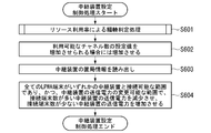
- FIG. 13 is a flowchart showing the flow of the relay device setting control process performed by the monitoring device 40 in the embodiment.
- the congestion determination unit 422 performs congestion determination processing based on the resource utilization rate (step S601).
- the relay device setting control unit 425 increases the set value of the number of available channels when it can be increased (step S602).
- the relay device setting control unit 425 reads out the station information database 432 stored in the storage unit 43 (step S603).
- the relay device setting control unit 425 is a relay device having a large number of connected terminals within a range in which all LPWA terminals 10 can be connected to any of the relay devices 20 and in a range in which the transmission power of the relay device 20 can be changed.
- the relay device 20 is controlled so as to reduce the transmission power of 20 and increase the transmission power of the relay device 20 having a small number of connected terminals (step S604).
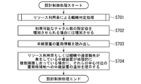
- FIG. 14 is a flowchart showing a flow of design control processing performed by the monitoring device 40 in the embodiment.
- the congestion determination unit 422 performs congestion determination processing based on the resource utilization rate (step S701).
- the design control unit 426 increases the set value of the number of available channels when it can be increased (step S702).
- the design control unit 426 reads out the station information database 432 stored in the storage unit 43 (step S703).
- the design control unit 426 of the relay device 20 to a candidate site for stationing near the center of the relay devices 20 Decide to add.
- the display control unit 428 presents the determined information to the user via the display unit 45 (step S704).
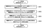
- FIG. 15 is a flowchart showing a flow of user setting control processing performed by the monitoring device 40 in the embodiment.
- the terminal setting control unit 427 adds a congestion correspondence mark to the downlink communication packet to the LPWA terminal 10 for which the congestion determination has been made (step S801).
- the congestion correspondence mark is a mark given to distinguish it from a normal packet.
- the terminal setting control unit 427 sets the magnification of the LPWA terminal 10 so as to reduce the transmission frequency of the packet to which the congestion correspondence mark is given according to the degree of congestion (step S802).
- the terminal setting control unit 427 sets the magnification of the LPWA terminal 10 so as to take a long timeout interval of the packet to which the congestion correspondence mark is given (step S803).
- the terminal setting control unit 427 sets the magnification of the LPWA terminal 10 so as to increase the number of retransmissions of the packet to which the congestion correspondence mark is given (step S804).
- FIG. 16 is a flowchart showing a flow of user setting control processing performed by the monitoring device 40 in the embodiment. Note that FIG. 16 describes a user setting control process using life and death information.
- the terminal setting control unit 427 adds a failure response mark to the downlink communication packet transmitted to the LPWA terminal 10 for which the failure determination has been made (step S901).
- the fault handling mark is a mark given to distinguish it from a normal packet.
- the terminal setting control unit 427 controls the setting of the LPWA terminal 10 so that when a packet with a failure response mark arrives, a non-delivery notification is immediately returned to the packet sender (step S902).
- the monitoring agent 30 responds to the request from the monitoring device 40 on behalf of the LPWA terminal 10. Specifically, the monitoring agent 30 periodically acquires information on the communication status of the LPWA terminal 10 from the relay device 20. Then, when the monitoring device 40 receives a monitoring request, the monitoring agent 30 generates a response to the monitoring request based on the information regarding the communication state of the LPWA terminal 10, and transmits the generated response to the monitoring device 40. As a result, the LPWA terminal 10 and the monitoring device 40 do not directly communicate with each other. Therefore, the LPWA terminal 10 does not have to respond to the monitoring request. Therefore, it is possible to suppress the power consumption of the LPWA terminal 10.
- a plurality of LPWA terminals 10 are aggregated into a group with one IP address and monitored.
- the unit of aggregation is an LPWA terminal 10 or the like connected to the same relay device 20.
- the relay device 20 to which the LPWA terminal 10 in the monitoring system 100 is connected has a simplified function, it generally does not have a function of grasping and managing the LPWA terminal 10. Therefore, in the present embodiment, it is not necessary for the relay device 20 to have a function of monitoring the LPWA terminal 10. Therefore, the cost of the relay device 20 can be suppressed.
- the LPWA terminal 10 may transmit the measurement result to the relay device 20 at intervals instructed by the relay device 20.
- the first communication unit 31 and the second communication unit 34 included in the monitoring agent may be composed of one communication unit.
- the first communication unit 41 and the second communication unit 44 included in the monitoring device 40 may be composed of one communication unit.
- the measurement result may include only one of the terminal ID and the terminal address.
- the congestion determination unit 422, the communication quality estimation unit 423, and the failure determination unit 424 may be configured as a state determination unit for determining the state of the LPWA terminal 10. When configured in this way, the state determination unit performs any or all of congestion determination, communication quality estimation, and failure determination as status monitoring of the LPWA terminal 10.
- the relay device setting control unit 425, the design control unit 426, and the terminal setting control unit 427 may be configured as the setting design control unit.
- the setting design control unit performs any or all of the setting control of the relay device 20 to which the LPWA terminal 10 is connected, the network design control, and the setting control of the LPWA terminal 10.
- the setting design control unit controls the setting of the relay device 20 to which the LPWA terminal 10 is connected, the network design control, and the setting of the LPWA terminal 10 based on either the communication quality or the amount of interference with other systems in addition to the resource utilization rate. Any or all of the controls may be performed.
Landscapes
- Engineering & Computer Science (AREA)
- Computer Networks & Wireless Communication (AREA)
- Signal Processing (AREA)
- Theoretical Computer Science (AREA)
- Environmental & Geological Engineering (AREA)
- Physics & Mathematics (AREA)
- General Engineering & Computer Science (AREA)
- General Physics & Mathematics (AREA)
- Computing Systems (AREA)
- Quality & Reliability (AREA)
- Mobile Radio Communication Systems (AREA)
- Data Exchanges In Wide-Area Networks (AREA)
Abstract
低電力で通信を行う低電力端末の通信状態に関する情報を保持する監視エージェントと、低電力端末の状態を監視する監視装置とを備える監視システムであって、監視装置は、低電力端末の通信状態に関する情報を要求する要求部、を備え、監視エージェントは、低電力端末の通信状態に関する情報に基づいて、監視装置からの要求に応じた応答を生成する応答生成部と、応答を監視装置に送信する送信部と、を備える監視システム。
Description
本発明は、監視システムに関する。
従来、通信インフラの監視にはSNMP(Simple Network Management Protocol)が利用されている(非特許文献1参照)。SNMPを利用した監視では、監視装置が、監視対象の機器から定常的に状態情報を取得することで状態監視を行う。このようなSNMPを利用した監視は、センサのようなIoT(Internet of Things)機器にも利用されている。
"A Simple Network Management Protocol (SNMP)"、Network Working Group、[平成31年3月15日検索]、インターネット<URL: https://tools.ietf.org/html/rfc1157>
ところで、一般的には、IoT向け無線通信技術としてLPWA(Low Power Wide Area)が利用されている。LPWAを利用する端末は、バッテリー駆動の端末が多く、電池容量が極めて小さい。したがって、SNMPを利用した監視による定常的な監視用通信に応答していると、LPWAを利用する端末の電池持ちが著しく悪化する。そのため、LPWAを利用する端末の状態監視を行う場合に、低電力で通信を行う端末の消費電力を抑制することが求められている。なお、このような問題は、SNMPを利用した監視に限らず、その他の監視用通信プロトコルを利用した監視においても同様に生じる問題である。
上記事情に鑑み、本発明は、低電力で通信を行う端末の消費電力を抑制することができる技術の提供を目的としている。
本発明の一態様は、低電力で通信を行う低電力端末の通信状態に関する情報を保持する監視エージェントと、前記低電力端末の状態を監視する監視装置とを備える監視システムであって、前記監視装置は、前記低電力端末の通信状態に関する情報を要求する要求部、を備え、前記監視エージェントは、前記低電力端末の通信状態に関する情報に基づいて、前記監視装置からの要求に応じた応答を生成する応答生成部と、前記応答を前記監視装置に送信する送信部と、を備える監視システムである。
本発明の一態様は、上記の監視システムであって、前記監視エージェントは、複数の前記低電力端末を1つのアドレス情報でグループ化し、前記応答生成部は、グループ単位で前記監視装置からの要求に応じた応答を生成する。
本発明の一態様は、上記の監視システムであって、前記監視装置は、前記応答に含まれる情報に基づいて、前記低電力端末の状態を判定する状態判定部をさらに備え、前記状態判定部は、前記応答に含まれる情報に基づいて、輻輳判定、通信品質推定、障害判定のいずれか又は全てを前記低電力端末の状態監視として行う。
本発明の一態様は、上記の監視システムであって、前記状態監視の結果に基づいて、前記低電力端末が接続する中継装置の設定制御、ネットワーク設計制御、及び前記低電力端末の設定制御のいずれか又は全てを行う設定設計制御部をさらに備える。
本発明の一態様は、上記の監視システムであって、前記状態判定部は、グループ内のトラフィック量及び他システム干渉時間率に基づいてリソース利用率及び他システム干渉量を算出し、グループ内の通信頻度及び受信信号強度に基づいて前記グループ内の通信品質を推定し、通信頻度及びパケット損失率に基づいて、前記グループ内の故障箇所を推定する。
本発明の一態様は、上記の監視システムであって、前記設定設計制御部は、リソース利用率、通信品質、他システム干渉量、もしくは故障箇所に応じて、前記中継装置におけるチャネル設定又は送信出力、前記中継装置と前記低電力端末とを含むグループ内の通信経路、前記前記低電力端末の設定のいずれかを制御する。
本発明の一態様は、上記の監視システムであって、前記設定設計制御部は、リソース利用率、通信品質、他システム干渉量のいずれかに基づいて、通信負荷を平準化するように前記中継装置の増減設又は前記中継装置の配置変更を前記ネットワーク設計制御として行う。
本発明により、低電力で通信を行う端末の消費電力を抑制することが可能となる。
以下、本発明の一実施形態を、図面を参照しながら説明する。
図1は、本発明における監視システム100のシステム構成を表す構成図である。監視システム100は、LPWA端末10、中継装置20、監視エージェント30、監視装置40及びユーザサーバ50を備える。なお、監視システム100は、LPWA端末10及び中継装置20を2台以上が備えてもよい。
図1は、本発明における監視システム100のシステム構成を表す構成図である。監視システム100は、LPWA端末10、中継装置20、監視エージェント30、監視装置40及びユーザサーバ50を備える。なお、監視システム100は、LPWA端末10及び中継装置20を2台以上が備えてもよい。
LPWA端末10は、バッテリーで駆動し、LPWAを利用して中継装置20との間で通信を行う。LPWA端末10は、例えば、環境の計測を行うセンサである。環境は、例えば温度、湿度、水量等である。LPWA端末10は、定期的(例えば、10分毎、1時間毎)に計測結果を中継装置20に送信する。計測結果には、端末ID、端末アドレス及び計測値が含まれる。なお、LPWA端末10は、センサに限らず、LPWAを利用し、かつ、バッテリー駆動の端末であればどのような端末であってもよい。LPWAとして、LoRa(登録商標)、SIGFOX(登録商標)、NB-IoT(Narrow Band IoT)のいずれが用いられてもよい。
中継装置20は、自装置に接続するLPWA端末10との間のデータ通信の記録を保持し、定期的に監視エージェント30に送信する。データ通信の記録には、端末ID、端末アドレス、通信記録時刻、受信信号強度(電波強度)、無線チャネル及びペイロードサイズ等が含まれる。また、中継装置20は、ユーザサーバ50から送信される情報をLPWA端末10に送信する。また、中継装置20は、監視装置40から送信される情報に基づいて自装置の設定を変更する。
監視エージェント30は、中継装置20から送信されたデータ通信の記録を保持する。監視エージェント30は、監視装置40から送信された監視用要求に応じた応答を作成し、作成した応答を監視装置40に送信する。監視エージェント30は、LPWA端末10の代理で、LPWA端末10の通信状態に関する情報を応答として監視装置40に送信する。監視エージェント30は、例えばノートパソコン、パーソナルコンピュータ、スマートフォン、携帯電話、タブレット端末、ゲーム機器等の情報処理装置を用いて構成される。
監視装置40は、監視用通信プロトコル(例えば、SNMP)を実装し、監視エージェント30に対してデータ通信記録の送信を要求する。監視装置40は、得られたデータ通信記録に基づいて、LPWA端末10及び中継装置20の状態監視を行う。状態監視は、例えば輻輳判定、通信品質推定及び故障判定である。監視装置40は、状態監視の結果に基づいて、中継装置20の設定制御、ネットワークの設計制御及びLPWA端末10の設定制御を行う。監視装置40は、例えばノートパソコン、パーソナルコンピュータ、スマートフォン、携帯電話、タブレット端末、ゲーム機器等の情報処理装置を用いて構成される。
監視装置40は、グループ単位で、グループに属するLPWA端末10及び中継装置20の状態監視を行う。グループの単位は、特に限定される必要はない。例えば、同じ中継装置20に接続するLPWA端末10で構成されていてもよいし、複数の中継装置20が1つのグループは属していてもよい。以下の説明では、同じ中継装置20に接続するLPWA端末10で構成されるグループ単位で状態監視を行う場合を例に説明する。各グループは、監視エージェント30に対して、グループを識別するために割り当てられているIPアドレスで識別される。
ユーザサーバ50は、監視装置40からの指示に応じて、中継装置20を介して、LPWA端末10の設定を制御する。ユーザサーバ50は、例えばノートパソコン、パーソナルコンピュータ、スマートフォン、携帯電話、タブレット端末、ゲーム機器等の情報処理装置を用いて構成される。
図2は、実施形態における監視エージェント30の機能構成を表す概略ブロック図である。
監視エージェント30は、バスで接続されたCPU(Central Processing Unit)やメモリや補助記憶装置などを備え、監視プログラムを実行する。監視プログラムの実行によって、監視エージェント30は、第1通信部31、制御部32、記憶部33及び第2通信部34を備える装置として機能する。なお、監視エージェント30の各機能の全て又は一部は、ASIC(Application Specific Integrated Circuit)やPLD(Programmable Logic Device)やFPGA(Field Programmable Gate Array)等のハードウェアを用いて実現されてもよい。また、監視プログラムは、コンピュータ読み取り可能な記録媒体に記録されてもよい。コンピュータ読み取り可能な記録媒体とは、例えばフレキシブルディスク、光磁気ディスク、ROM、CD-ROM等の可搬媒体、コンピュータシステムに内蔵されるハードディスク等の記憶装置である。また、監視プログラムは、電気通信回線を介して送受信されてもよい。
監視エージェント30は、バスで接続されたCPU(Central Processing Unit)やメモリや補助記憶装置などを備え、監視プログラムを実行する。監視プログラムの実行によって、監視エージェント30は、第1通信部31、制御部32、記憶部33及び第2通信部34を備える装置として機能する。なお、監視エージェント30の各機能の全て又は一部は、ASIC(Application Specific Integrated Circuit)やPLD(Programmable Logic Device)やFPGA(Field Programmable Gate Array)等のハードウェアを用いて実現されてもよい。また、監視プログラムは、コンピュータ読み取り可能な記録媒体に記録されてもよい。コンピュータ読み取り可能な記録媒体とは、例えばフレキシブルディスク、光磁気ディスク、ROM、CD-ROM等の可搬媒体、コンピュータシステムに内蔵されるハードディスク等の記憶装置である。また、監視プログラムは、電気通信回線を介して送受信されてもよい。
第1通信部31は、中継装置20との間で通信を行う。第1通信部31は、データ通信の記録を中継装置20から受信する。
制御部32は、CPU等のプロセッサやメモリを用いて構成される。制御部32は、データ記録部321及び応答生成部322として機能する。
データ記録部321は、第1通信部31によって受信されたデータ通信記録に対して、端末IDに応じた所定のIPアドレスを対応付けて記憶部33に記録する。所定のIPアドレスは、端末ID毎に予め対応付けられている。例えば、1つのグループに属するLPWA端末10の端末IDには、同じIPアドレスが対応付けられる。これにより、グループ単位で情報の管理が可能になる。
応答生成部322は、監視エージェント30から送信された監視用要求に応じた応答を生成する。
制御部32は、CPU等のプロセッサやメモリを用いて構成される。制御部32は、データ記録部321及び応答生成部322として機能する。
データ記録部321は、第1通信部31によって受信されたデータ通信記録に対して、端末IDに応じた所定のIPアドレスを対応付けて記憶部33に記録する。所定のIPアドレスは、端末ID毎に予め対応付けられている。例えば、1つのグループに属するLPWA端末10の端末IDには、同じIPアドレスが対応付けられる。これにより、グループ単位で情報の管理が可能になる。
応答生成部322は、監視エージェント30から送信された監視用要求に応じた応答を生成する。
記憶部33は、対応付けデータベース331、通信記録データベース332及び解析表333を記憶する。記憶部33は、磁気ハードディスク装置や半導体記憶装置などの記憶装置を用いて構成される。
対応付けデータベース331は、図3に示す構成を有しており、端末IDとIPアドレスとが対応付けて登録されたデータベースである。図3は、対応付けデータベース331の一例を示す図である。対応付けデータベース331は、端末IDとIPアドレスとの対応付けに関する情報を表すレコードを複数有する。レコードは、端末ID及びIPアドレスの各値を有する。端末IDは、LPWA端末10を識別するための識別情報を表す。IPアドレスは、端末IDに対応付ける対象となるIPアドレスを表す。IPアドレスは、監視エージェント30に割り当てられたIPアドレスである。
対応付けデータベース331は、図3に示す構成を有しており、端末IDとIPアドレスとが対応付けて登録されたデータベースである。図3は、対応付けデータベース331の一例を示す図である。対応付けデータベース331は、端末IDとIPアドレスとの対応付けに関する情報を表すレコードを複数有する。レコードは、端末ID及びIPアドレスの各値を有する。端末IDは、LPWA端末10を識別するための識別情報を表す。IPアドレスは、端末IDに対応付ける対象となるIPアドレスを表す。IPアドレスは、監視エージェント30に割り当てられたIPアドレスである。
図3に示される例では、対応付けデータベース331には複数の端末IDが登録されている。これらの端末IDは、“ED-1”、“ED-2”である。図3において、対応付けデータベース331の最上段に登録されているレコードは、端末IDの値が“ED-1”、IPアドレスの値が“vvv”である。すなわち、端末ID“ED-1”で識別されるLPWA端末10に関するデータ通信記録にはIPアドレス“vvv”が対応付けられることが表されている。
通信記録データベース332は、図4に示す構成を有しており、データ通信記録に関する情報が登録されたデータベースである。図4は、通信記録データベース332の一例を示す図である。通信記録データベース332は、データ通信記録に関する情報を表すレコードを複数有する。レコードは、端末ID、IPアドレス、通信記録時刻、受信信号強度、無線チャネル及びペイロードサイズの各値を有する。端末IDは、LPWA端末10を識別するための識別情報を表す。IPアドレスは、端末IDに対応付ける対象となるIPアドレスを表す。通信記録時刻は、中継装置20で計測結果が受信された時刻を表す。受信信号強度は、中継装置20で計測結果が受信された際の信号強度を表す。無線チャネルは、中継装置20で計測結果が受信された際のチャネルを表す。ペイロードサイズは、中継装置20で受信された計測結果のペイロードのサイズを表す。
図4に示される例では、通信記録データベース332には複数の端末IDが登録されている。これらの端末IDは、“ED-1”、“ED-2”である。図4において、通信記録データベース332の最上段に登録されているレコードは、端末IDの値が“ED-1”、IPアドレスの値が“vvv”、通信記録時刻の値が“YYMMDD”、受信信号強度の値が“-100dB”、無線チャネルの値が“CH1”、ペイロードサイズの値が“100byte”である。すなわち、端末ID“ED-1”で識別されるLPWA端末10に関するデータ通信記録にはIPアドレス“vvv”が対応付けられており、計測結果が受信された時刻が“YYMMDD”であり、計測結果が受信された際の信号強度が“-100dB”であり、計測結果が受信された際のチャネルが“CH1”であり、計測結果のペイロードのサイズが“100byte”であることが表されている。
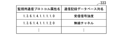
解析表333は、図5に示す構成を有しており、監視用通信プロトコルで指定された情報と、解析後の情報とが対応付けて登録されたデータベースである。図5は、解析表333の一例を示す図である。解析表333は、監視用通信プロトコルで指定された情報と、解析後の情報とが対応付けられたレコードを複数有する。レコードは、監視用通信プロトコル属性名及び通信記録データベース列名の各値を有する。監視用通信プロトコル属性名は、監視用通信プロトコルで指定する個々の情報の識別子を表す。例えば、監視用通信プロトコル属性名は、OIDである。通信記録データベース列名は、監視用通信プロトコル属性名に対応する通信記録データベース332の列の名前を表す。
図5に示される例では、解析表333には複数の監視用通信プロトコル属性名が登録されている。これらの監視用通信プロトコル属性名は、“1.3.6.1.4.1.1.1.1.0”、“1.3.6.1.4.1.1.1.2.0”である。図5において、解析表333の最上段に登録されているレコードは、監視用通信プロトコル属性名の値が“ED-1”、IPアドレスの値が“vvv”、通信記録時刻の値が“1.3.6.1.4.1.1.1.1.0”、通信記録データベース列名の値が“受信信号強度”である。すなわち、監視用通信プロトコルで指定された情報の識別子が“1.3.6.1.4.1.1.1.1.0”である場合、識別子が示している情報が“受信信号強度”であることが表されている。
図2に戻って説明を続ける。
第2通信部34は、監視装置40との間で通信を行う。例えば、第2通信部34は、監視用要求を監視装置40から受信し、受信した監視用要求で指定されている情報を応答として監視装置40に送信する。監視用要求には、宛先IPアドレス及び監視用通信プロトコル属性名が含まれる。なお、監視用要求には、監視プロトコル属性名が複数含まれていてもよい。
第2通信部34は、監視装置40との間で通信を行う。例えば、第2通信部34は、監視用要求を監視装置40から受信し、受信した監視用要求で指定されている情報を応答として監視装置40に送信する。監視用要求には、宛先IPアドレス及び監視用通信プロトコル属性名が含まれる。なお、監視用要求には、監視プロトコル属性名が複数含まれていてもよい。
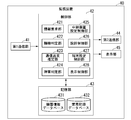
図6は、実施形態における監視装置40の機能構成を表す概略ブロック図である。
監視装置40は、バスで接続されたCPUやメモリや補助記憶装置などを備え、監視プログラムを実行する。監視プログラムの実行によって、監視装置40は、第1通信部41、制御部42、記憶部43、第2通信部44、表示部45を備える装置として機能する。なお、監視装置40の各機能の全て又は一部は、ASICやPLDやFPGA等のハードウェアを用いて実現されてもよい。また、監視プログラムは、コンピュータ読み取り可能な記録媒体に記録されてもよい。コンピュータ読み取り可能な記録媒体とは、例えばフレキシブルディスク、光磁気ディスク、ROM、CD-ROM等の可搬媒体、コンピュータシステムに内蔵されるハードディスク等の記憶装置である。また、監視プログラムは、電気通信回線を介して送受信されてもよい。
監視装置40は、バスで接続されたCPUやメモリや補助記憶装置などを備え、監視プログラムを実行する。監視プログラムの実行によって、監視装置40は、第1通信部41、制御部42、記憶部43、第2通信部44、表示部45を備える装置として機能する。なお、監視装置40の各機能の全て又は一部は、ASICやPLDやFPGA等のハードウェアを用いて実現されてもよい。また、監視プログラムは、コンピュータ読み取り可能な記録媒体に記録されてもよい。コンピュータ読み取り可能な記録媒体とは、例えばフレキシブルディスク、光磁気ディスク、ROM、CD-ROM等の可搬媒体、コンピュータシステムに内蔵されるハードディスク等の記憶装置である。また、監視プログラムは、電気通信回線を介して送受信されてもよい。
第1通信部41は、監視エージェント30との間で通信を行う。例えば、第1通信部41は、監視用要求を監視エージェント30に送信し、監視用要求に対する応答を監視エージェント30から受信する。
制御部42は、CPU等のプロセッサやメモリを用いて構成される。制御部42は、情報要求部421、輻輳判定部422、通信品質推定部423、障害判定部424、中継装置設定制御部425、設計制御部426、端末設定制御部427及び表示制御部428として機能する。
制御部42は、CPU等のプロセッサやメモリを用いて構成される。制御部42は、情報要求部421、輻輳判定部422、通信品質推定部423、障害判定部424、中継装置設定制御部425、設計制御部426、端末設定制御部427及び表示制御部428として機能する。
情報要求部421は、監視エージェント30に対してLPWA端末10の通信に関する情報を要求する。具体的には、情報要求部421は、監視用要求を生成し、生成した監視用要求を所定のアドレス宛に送信することによって、LPWA端末10の通信に関する情報を要求する。
輻輳判定部422は、応答に含まれるLPWA端末10の通信に関する情報に基づいて、輻輳判定処理を行う。輻輳判定処理とは、グループ内で輻輳が発生しているか否かを判定する処理である。本実施形態では、輻輳判定処理として、他システム干渉量による輻輳判定と、リソース利用率による輻輳判定とのいずれか又は両方が実行される。
通信品質推定部423は、応答に含まれるLPWA端末10の通信に関する情報に基づいて通信品質を推定する。具体的には、通信品質推定部423は、各LPWA端末10からの通信の呼損率及び受信信号強度を取得し、取得した呼損率及び受信信号強度をグループ内の全LPWA端末10分合算することによって、グループ全体として予め定めたサービス水準を満たすかを判定する。
障害判定部424は、応答に含まれるLPWA端末10の通信に関する情報に基づいて障害判定処理を行う。障害判定処理とは、グループ内における障害の有無及び障害の原因を判定する処理である。本実施形態では、障害判定部424は、中継装置20の死活状態と、中継装置20と通信可能な複数のLPWA端末10からの通信到達率とに基づいて、通信障害の原因が中継装置20、無線区間の通信品質、及びLPWA端末10のいずれに由来するかを判定する。
中継装置設定制御部425は、状態監視の結果に基づいて、中継装置20の設定を制御する。具体的には、中継装置設定制御部425は、監視結果から算出されるリソース利用率を用いて中継装置20のチャネル設定及び送信電力等の中継装置20の設定を制御する。
設計制御部426は、状態監視の結果に基づいて、ネットワークの設計を制御する。具体的には、設計制御部426は、通信負荷を平準化するような、グループ内における中継装置20もしくは他のネットワーク装置の増減設もしくは配置変更を提示する。
設計制御部426は、状態監視の結果に基づいて、ネットワークの設計を制御する。具体的には、設計制御部426は、通信負荷を平準化するような、グループ内における中継装置20もしくは他のネットワーク装置の増減設もしくは配置変更を提示する。
端末設定制御部427は、状態監視の結果に基づいて、LPWA端末10又はユーザアプリケーションの設定を制御する。具体的には、端末設定制御部427は、状態監視の結果で示される輻輳情報や死活情報を用いて、LPWA端末10又はユーザアプリケーションの設定を制御する。
表示制御部428は、表示部45を制御する。例えば、表示制御部428は、設計制御部426による配置変更の例を表示させてもよい。
表示制御部428は、表示部45を制御する。例えば、表示制御部428は、設計制御部426による配置変更の例を表示させてもよい。
記憶部43は、機器情報データベース431及び置局情報データベース432を記憶する。記憶部43は、磁気ハードディスク装置や半導体記憶装置などの記憶装置を用いて構成される。
機器情報データベース431は、監視エージェント30から得られた情報を端末IDに対応付けて記憶する。
機器情報データベース431は、監視エージェント30から得られた情報を端末IDに対応付けて記憶する。
置局情報データベース432は、各装置の配置位置に関する情報を登録されたデータベースである。例えば、置局情報データベース432には、各装置(LPWA端末10及び中継装置20)の識別情報と、配置位置とが対応付けて登録されている。各装置の識別情報は、LPWA端末10及び中継装置20それぞれを識別するための情報である。例えば、LPWA端末10の識別情報は、LPWA端末10のMACアドレスであってもよいし、LPWA端末10毎に固有の情報であってもよい。また、例えば、中継装置20の識別情報は、中継装置20のMACアドレスであってもよいし、中継装置20毎に固有の情報であってもよい。配置位置は、LPWA端末10及び中継装置20が配置されている位置の情報を表す。例えば、配置位置は、緯度経度である。
第2通信部44は、中継装置20及びユーザサーバ50との間で通信を行う。
第2通信部44は、中継装置20及びユーザサーバ50との間で通信を行う。
表示部45は、液晶ディスプレイ、有機EL(Electro Luminescence)ディスプレイ、CRT(Cathode Ray Tube)ディスプレイ等の画像表示装置である。表示部45は、監視装置40を表示する。表示部45は、画像表示装置を監視装置40に接続するためのインタフェースであってもよい。この場合、表示部45は、監視装置40を表示するための映像信号を生成し、自身に接続されている画像表示装置に映像信号を出力する。
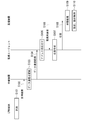
図7は、実施形態における監視システム100の流れを示すシーケンス図である。
LPWA端末10は、環境を計測する(ステップS101)。LPWA端末10は、計測結果を定期的に中継装置20に送信する(ステップS102)。
中継装置20は、LPWA端末10から送信された計測結果を受信する。この際、中継装置20は、計測結果の受信時刻を取得するとともに、受信信号強度を測定する。中継装置20は、計測結果に、受信時刻、受信信号強度、無線チャネル及びペイロードサイズを対応付けて、データ通信記録として記録する(ステップS103)。
上記のステップS101~103は、定期的に実行される。
LPWA端末10は、環境を計測する(ステップS101)。LPWA端末10は、計測結果を定期的に中継装置20に送信する(ステップS102)。
中継装置20は、LPWA端末10から送信された計測結果を受信する。この際、中継装置20は、計測結果の受信時刻を取得するとともに、受信信号強度を測定する。中継装置20は、計測結果に、受信時刻、受信信号強度、無線チャネル及びペイロードサイズを対応付けて、データ通信記録として記録する(ステップS103)。
上記のステップS101~103は、定期的に実行される。
中継装置20は、データ通信記録を定期的に監視エージェント30に送信する(ステップS104)。
監視エージェント30の第1通信部31は、中継装置20から送信されたデータ通信記録を受信する。第1通信部31は、受信したデータ通信記録をデータ記録部321に出力する。データ記録部321は、データ通信記録と、対応付けデータベース331とに基づいて、データ通信記録をIPアドレスに対応付ける(ステップS105)。具体的には、まずデータ記録部321は、記憶部33から対応付けデータベース331を読み出す。次に、データ記録部321は、読みだした対応付けデータベース331の端末IDの項目を参照し、データ通信記録に含まれる端末IDに対応するレコードを取得する。次に、データ記録部321は、取得したレコードのIPアドレスの項目に登録されているIPアドレスを取得する。そして、データ記録部321は、取得したIPアドレスをデータ通信記録に対応付けて通信記録データベース332に新たに登録する。
監視エージェント30の第1通信部31は、中継装置20から送信されたデータ通信記録を受信する。第1通信部31は、受信したデータ通信記録をデータ記録部321に出力する。データ記録部321は、データ通信記録と、対応付けデータベース331とに基づいて、データ通信記録をIPアドレスに対応付ける(ステップS105)。具体的には、まずデータ記録部321は、記憶部33から対応付けデータベース331を読み出す。次に、データ記録部321は、読みだした対応付けデータベース331の端末IDの項目を参照し、データ通信記録に含まれる端末IDに対応するレコードを取得する。次に、データ記録部321は、取得したレコードのIPアドレスの項目に登録されているIPアドレスを取得する。そして、データ記録部321は、取得したIPアドレスをデータ通信記録に対応付けて通信記録データベース332に新たに登録する。
監視装置40の情報要求部421は、ユーザの指示又は予め定められたタイミングで、監視用通信プロトコルに基づく監視用要求を生成する。情報要求部421は、第1通信部41を制御して、生成した監視用要求を宛先の監視エージェント30に送信する(ステップS106)。
第2通信部34は、監視装置40から送信された監視用要求を受信する。第2通信部34は、受信した監視用要求を応答生成部322に出力する。応答生成部322は、監視用要求に応じた応答を生成する(ステップS107)。具体的には、まず応答生成部322は、記憶部33に記憶されている解析表333を読み出す。次に、応答生成部322は、読み出した解析表333を参照し、監視用要求に含まれる監視プロトコル属性名を解析する。例えば、監視用通信プロトコル属性名として“1.3.6.1.4.1.1.1.1.0”の値が監視用要求に含まれている場合、応答生成部322は、読み出した解析表333を参照し、監視用要求に含まれる監視プロトコル属性名“1.3.6.1.4.1.1.1.1.0”を、通信記録データベース332の列名の“受信信号強度”であると解析する。
次に、応答生成部322は、通信記録データベース332のIPアドレスを参照し、監視用要求に含まれるIPアドレスに対応するレコードを取得する。次に、応答生成部322は、取得したレコードに登録されている項目のうち、解析された列名に対応する項目の値を取得する。そして、応答生成部322は、取得した解析された列名に対応する項目の値を含む応答を生成する。応答生成部322は、第2通信部44を制御して、生成した応答を監視装置40に送信する(ステップS108)。
第1通信部41は、監視エージェント30から送信された応答を受信する。第1通信部41は、受信した応答を制御部42に出力する。制御部42は、応答を機器情報データベース431に記録する。その後、制御部42は、機器情報データベース431に登録されている情報に基づいて状態監視を行う(ステップS109)。監視装置40が行う状態監視は、輻輳判定、通信品質推定及び障害判定である。各状態監視の詳細については後述する。制御部42は、状態監視の結果に基づいて、各機器(LPWA端末10及び中継装置20)の設定制御及びネットワークの設計制御のいずれか又は全てを行う(ステップS110)。各機器の設定制御及びネットワークの設計制御の詳細については後述する。
図8は、実施形態における監視装置40が行う輻輳判定処理の流れを示すフローチャートである。なお、図8では、他システム干渉量による輻輳判定処理について説明する。 輻輳判定部422は、中継装置20からある期間内(例えば、1時間内)にキャリアセンスにより電波の受信を停止していた合計の停止時間長Nを取得する(ステップS201)。輻輳判定部422は、中継装置20からある期間内(例えば、1時間内)に他システム宛を含むLPWA端末10のパケットを受信することにより消費した合計の消費時間長Lを取得する(ステップS202)。
輻輳判定部422は、LPWA端末10の複数が中継装置20を用いて上り通信を行った合計の上り通信時間長Sを取得する(ステップS203)。輻輳判定部422は、取得した停止時間長N、消費時間長L及び上り通信時間長Sに基づいて、他システムの通信量(他システム干渉量)を算出する(ステップS204)。具体的には、輻輳判定部422は、以下の式(1)に基づいて他システムの通信量(他システム干渉量)を算出する。
他システム干渉量=停止時間長N+消費時間長L-上り通信時間長S・・・(1)
輻輳判定部422は、算出した他システム干渉量が一定の基準以上であるか否かを判定する(ステップS205)。算出した他システム干渉量が一定の基準以上である場合(ステップS205-YES)、輻輳判定部422は輻輳が発生していると判定する(ステップS206)。
一方、算出した他システム干渉量が一定の基準未満である場合(ステップS205-NO)、輻輳判定部422は輻輳が発生していないと判定する(ステップS207)。
一方、算出した他システム干渉量が一定の基準未満である場合(ステップS205-NO)、輻輳判定部422は輻輳が発生していないと判定する(ステップS207)。
図9は、実施形態における監視装置40が行う輻輳判定処理の流れを示すフローチャートである。なお、図9では、リソース利用率による輻輳判定処理について説明する。
輻輳判定部422は、中継装置20のトポロジ情報を中継装置20から取得する(ステップS301)。トポロジ情報とは、中継装置20に接続している全ての機器と、各機器を結ぶ経路の情報とが示された情報である。トポロジ情報により、中継装置20に対してどのような機器が接続されているのか、各機器がどのような経路で接続されているのか等の情報を取得することができる。輻輳判定部422は、取得したトポロジ情報から各LPWA端末10の上り通信と下り通信のそれぞれの経路で使用されるリソースを算出して集計する(ステップS302)ここで、リソースは、無線チャネル、中継装置20、有線リンク及びユーザサーバ50等である。
輻輳判定部422は、中継装置20のトポロジ情報を中継装置20から取得する(ステップS301)。トポロジ情報とは、中継装置20に接続している全ての機器と、各機器を結ぶ経路の情報とが示された情報である。トポロジ情報により、中継装置20に対してどのような機器が接続されているのか、各機器がどのような経路で接続されているのか等の情報を取得することができる。輻輳判定部422は、取得したトポロジ情報から各LPWA端末10の上り通信と下り通信のそれぞれの経路で使用されるリソースを算出して集計する(ステップS302)ここで、リソースは、無線チャネル、中継装置20、有線リンク及びユーザサーバ50等である。
輻輳判定部422は、各リソースの利用率が一定の基準以上であるか否かを判定する(ステップS303)。各リソースの利用率が一定の基準以上である場合(ステップS303-YES)、輻輳判定部422は輻輳が発生していると判定する(ステップS304)。
一方、一部又は全てのリソースの利用率が一定の基準未満である場合(ステップS303-NO)、輻輳判定部422は輻輳が発生していないと判定する(ステップS305)。
上記のように、図9では、LPWA端末10のトラフィック量に基づいてリソース利用率が算出される。
一方、一部又は全てのリソースの利用率が一定の基準未満である場合(ステップS303-NO)、輻輳判定部422は輻輳が発生していないと判定する(ステップS305)。
上記のように、図9では、LPWA端末10のトラフィック量に基づいてリソース利用率が算出される。
図10は、実施形態における監視装置40が行う通信品質推定処理の流れを示すフローチャートである。
通信品質推定部423は、上り通信の想定頻度の設定値とサービス水準の呼損率、電波強度の基準値及び電波強度の基準値を上回る電波強度の想定頻度を取得する(ステップS401)。呼損率は、通信回線の容量不足により、着呼できない状態が発生する確率を表す。呼損率は、上り通信の想定頻度と、データ通信記録から導出される頻度との比率に基づいて算出される。
通信品質推定部423は、上り通信の想定頻度の設定値とサービス水準の呼損率、電波強度の基準値及び電波強度の基準値を上回る電波強度の想定頻度を取得する(ステップS401)。呼損率は、通信回線の容量不足により、着呼できない状態が発生する確率を表す。呼損率は、上り通信の想定頻度と、データ通信記録から導出される頻度との比率に基づいて算出される。
通信品質推定部423は、呼損率がサービス水準の呼損率以下であるか否かを判定する(ステップS402)。具体的には、まず通信品質推定部423は、データ通信記録から導出される上り通信の頻度を、上り通信の想定頻度で除算する。次に、通信品質推定部423は、1から除算結果を減算することによって呼損率を算出する。そして、通信品質推定部423は、算出した呼損率がサービス水準の呼損率以下であるかを判定する。呼損率がサービス水準の呼損率以下である場合(ステップS402-YES)、通信品質推定部423は通信記録から取得される上り通信の電波強度のうち、サービス水準の電波強度の基準値を上回る数X1を算出する(ステップS403)。
通信品質推定部423は、算出した数X1を、上り通信の想定頻度の設定値で除算することによって除算結果X2を算出する(ステップS404)。通信品質推定部423は、算出した除算結果X2が、サービス水準の基準値を上回る電波強度の想定頻度以上であるか否かを判定する(ステップS405)。除算結果X2が、サービス水準の基準値を上回る電波強度の想定頻度以上である場合(ステップS405-YES)、通信品質推定部423はサービス水準を満たすと判定する(ステップS406)。サービス水準を満たすということは、通信品質が良いことを表す。
一方、呼損率がサービス水準の呼損率より大きい場合(ステップS402-NO)、又は、除算結果X2が、サービス水準の基準値を上回る電波強度の想定頻度未満である場合(ステップS405-NO)、通信品質推定部423はサービス水準を満たさないと判定する(ステップS407)。サービス水準を満たさないということは、通信品質が悪いことを表す。
一方、呼損率がサービス水準の呼損率より大きい場合(ステップS402-NO)、又は、除算結果X2が、サービス水準の基準値を上回る電波強度の想定頻度未満である場合(ステップS405-NO)、通信品質推定部423はサービス水準を満たさないと判定する(ステップS407)。サービス水準を満たさないということは、通信品質が悪いことを表す。
図11及び図12は、実施形態における監視装置40が行う障害判定処理の流れを示すフローチャートである。なお、図11及び図12の処理は、いずれかのLPWA端末10で所定時間の間に通信記録がない場合に実行される。
障害判定部424は、所定時間の間に通信記録がないLPWA端末10において最後に通信記録がある中継装置20に対して応答確認を行う(ステップS501)。障害判定部424は、中継装置20から応答があるか否かを判定する(ステップS502)。中継装置20から応答がある場合(ステップS502-YES)、障害判定部424は応答を送信した中継装置20の無線IFは正常な稼働状態になっているか否かを判定する(ステップS503)。
障害判定部424は、所定時間の間に通信記録がないLPWA端末10において最後に通信記録がある中継装置20に対して応答確認を行う(ステップS501)。障害判定部424は、中継装置20から応答があるか否かを判定する(ステップS502)。中継装置20から応答がある場合(ステップS502-YES)、障害判定部424は応答を送信した中継装置20の無線IFは正常な稼働状態になっているか否かを判定する(ステップS503)。
正常な稼働状態になっている場合(ステップS503-YES)、障害判定部424は所定の時間の間にいずれかのチャネルでいずれかのLPWA端末10で通信記録があるか(ステップS504)。いずれかのチャネルでいずれかのLPWA端末10で通信記録がある(ステップS504-YES)、障害判定部424は置局情報データベース432を参照し、全てのLPWA端末10と全ての中継装置20との配置情報を取得する(ステップS505)。障害判定部424は、最後の通信記録が、応答を送信した中継装置20であり、かつ、所定の時間の間に通信記録がないLPWA端末10が当該LPWA端末10以外にもあるか否かを判定する(ステップS506)。
最後の通信記録が、応答を送信した中継装置20はなく、所定の時間の間に通信記録がないLPWA端末10が当該LPWA端末10以外にない条件のいずれか一方又は両方が満たされた場合(ステップS506-NO)、障害判定部424は端末固有の障害と判定する(ステップS507)。その後、監視装置40は、障害判定処理を終了する。
一方、最後の通信記録が、応答を送信した中継装置20であり、かつ、所定の時間の間に通信記録がないLPWA端末10が当該LPWA端末10以外にもある場合(ステップS506-YES)、障害判定部424は通信記録がないLPWA端末10が地理的に近い距離に複数台あるか否かを判定する(ステップS508)。
一方、最後の通信記録が、応答を送信した中継装置20であり、かつ、所定の時間の間に通信記録がないLPWA端末10が当該LPWA端末10以外にもある場合(ステップS506-YES)、障害判定部424は通信記録がないLPWA端末10が地理的に近い距離に複数台あるか否かを判定する(ステップS508)。
例えば、障害判定部424は、通信記録がないLPWA端末10間の地理的な距離が所定の距離未満である場合には、通信記録がないLPWA端末10が地理的に近い距離に複数台あると判定する。一方、障害判定部424は、通信記録がないLPWA端末10間の地理的な距離が所定の距離以上である場合には、通信記録がないLPWA端末10が地理的に近い距離に複数台ないと判定する。
通信記録がないLPWA端末10が地理的に近い距離に複数台ない場合(ステップS508-NO)、障害判定部424は端末固有の障害と判定する(ステップS507)。その後、監視装置40は、障害判定処理を終了する。
通信記録がないLPWA端末10が地理的に近い距離に複数台ない場合(ステップS508-NO)、障害判定部424は端末固有の障害と判定する(ステップS507)。その後、監視装置40は、障害判定処理を終了する。
一方、通信記録がないLPWA端末10が地理的に近い距離に複数台ある場合(ステップS508-YES)、障害判定部424はLPWA端末10の設置環境に由来する通信障害の可能性ありと判定する(ステップS509)。その後、監視装置40は、障害判定処理を終了する。
また、ステップS504の処理において、いずれかのチャネルでいずれかのLPWA端末10で通信記録がない場合(ステップS504-NO)、すなわちいずれのチャネルにおいてもいずれのLPWA端末10で通信記録がない場合には、輻輳判定部422は応答を送信した中継装置20の輻輳判定処理を行う(ステップS510)。
また、ステップS504の処理において、いずれかのチャネルでいずれかのLPWA端末10で通信記録がない場合(ステップS504-NO)、すなわちいずれのチャネルにおいてもいずれのLPWA端末10で通信記録がない場合には、輻輳判定部422は応答を送信した中継装置20の輻輳判定処理を行う(ステップS510)。
障害判定部424は、輻輳判定処理の結果として、他システムによる輻輳が発生しているか否かを判定する(ステップS511)。他システムによる輻輳が発生していると判定された場合(ステップS511-YES)、障害判定部424は他システム等の干渉による通信品質低下による通信障害と判定する(ステップS512)。その後、監視装置40は、障害判定処理を終了する。
一方、他システムによる輻輳が発生していると判定されなかった場合(ステップS511-NO)、障害判定部424は応答を送信した中継装置20の無線IFがサイレンと呼称であると判定する(ステップS513)。その後、監視装置40は、障害判定処理を終了する。
一方、他システムによる輻輳が発生していると判定されなかった場合(ステップS511-NO)、障害判定部424は応答を送信した中継装置20の無線IFがサイレンと呼称であると判定する(ステップS513)。その後、監視装置40は、障害判定処理を終了する。
また、ステップS503の処理において、正常な稼働状態になっていない場合(ステップS503-NO)、障害判定部424は応答があった中継装置の設置箇所に併設の試験端末に通信できるか否かを判定する(ステップS514)。応答があった中継装置の設置箇所に併設の試験端末に通信できる場合(ステップS514-YES)、障害判定部424はステップS504以降の処理を実行する。
一方、応答があった中継装置の設置箇所に併設の試験端末に通信できない場合(ステップS514-NO)、障害判定部424は応答があった中継装置の無線IFの故障と判定する(ステップS515)。その後、監視装置40は、障害判定処理を終了する。
一方、応答があった中継装置の設置箇所に併設の試験端末に通信できない場合(ステップS514-NO)、障害判定部424は応答があった中継装置の無線IFの故障と判定する(ステップS515)。その後、監視装置40は、障害判定処理を終了する。
また、ステップS502の処理において、中継装置20から応答がない場合(ステップS502-NO)、障害判定部424は応答がない中継装置からの上り通信の経路上にある中継装置20へ応答確認を行う(ステップS516)。障害判定部424は、中継装置20から応答があるか否かを判定する(ステップS517)。中継装置20から応答がある場合(ステップS517-YES)、障害判定部424は中継装置20もしくは中継装置20の有線IF又はリンクの故障と判定する(ステップS518)。その後、監視装置40は、障害判定処理を終了する。
一方、中継装置20から応答がない場合(ステップS517-NO)、障害判定部424は経路上の中継装置20の故障と判定する(ステップS519)。その後、監視装置40は、障害判定処理を終了する。
一方、中継装置20から応答がない場合(ステップS517-NO)、障害判定部424は経路上の中継装置20の故障と判定する(ステップS519)。その後、監視装置40は、障害判定処理を終了する。
図13は、実施形態における監視装置40が行う中継装置設定制御処理の流れを示すフローチャートである。
輻輳判定部422は、リソース利用率による輻輳判定処理を行う(ステップS601)。中継装置設定制御部425は、利用可能なチャネル数の設定値を増加させられる場合には増加させる(ステップS602)。中継装置設定制御部425は、記憶部43に記憶されている置局情報データベース432を読み出す(ステップS603)。中継装置設定制御部425は、全てのLPWA端末10がいずれかの中継装置20と接続可能な範囲であり、かつ、中継装置20の送信電力の変更可能な範囲で、接続端末数が多い中継装置20の送信電力を減少させ、接続端末数が少ない中継装置20の送信電力を増加させるように中継装置20を制御する(ステップS604)。
輻輳判定部422は、リソース利用率による輻輳判定処理を行う(ステップS601)。中継装置設定制御部425は、利用可能なチャネル数の設定値を増加させられる場合には増加させる(ステップS602)。中継装置設定制御部425は、記憶部43に記憶されている置局情報データベース432を読み出す(ステップS603)。中継装置設定制御部425は、全てのLPWA端末10がいずれかの中継装置20と接続可能な範囲であり、かつ、中継装置20の送信電力の変更可能な範囲で、接続端末数が多い中継装置20の送信電力を減少させ、接続端末数が少ない中継装置20の送信電力を増加させるように中継装置20を制御する(ステップS604)。
図14は、実施形態における監視装置40が行う設計制御処理の流れを示すフローチャートである。
輻輳判定部422は、リソース利用率による輻輳判定処理を行う(ステップS701)。設計制御部426は、利用可能なチャネル数の設定値を増加させられる場合には増加させる(ステップS702)。設計制御部426は、記憶部43に記憶されている置局情報データベース432を読み出す(ステップS703)。設計制御部426は、リソース利用率もしくは輻輳や通信損失が発生している中継装置20が地理的に複数隣接し合っている場合に、それらの中心付近の置局候補地への中継装置20の追加を決定する。表示制御部428は、決定された情報を、表示部45を介してユーザに提示する(ステップS704)。
輻輳判定部422は、リソース利用率による輻輳判定処理を行う(ステップS701)。設計制御部426は、利用可能なチャネル数の設定値を増加させられる場合には増加させる(ステップS702)。設計制御部426は、記憶部43に記憶されている置局情報データベース432を読み出す(ステップS703)。設計制御部426は、リソース利用率もしくは輻輳や通信損失が発生している中継装置20が地理的に複数隣接し合っている場合に、それらの中心付近の置局候補地への中継装置20の追加を決定する。表示制御部428は、決定された情報を、表示部45を介してユーザに提示する(ステップS704)。
図15は、実施形態における監視装置40が行うユーザ設定制御処理の流れを示すフローチャートである。なお、図15では、輻輳情報を用いたユーザ設定制御処理について説明する。
端末設定制御部427は、輻輳判定が行われたLPWA端末10への下り通信パケットに輻輳対応マークを付与する(ステップS801)。輻輳対応マークは、通常のパケットと区別するために付与されるマークである。端末設定制御部427は、輻輳対応マークの付与されたパケットの送信頻度を輻輳度合いに応じて下げるようにLPWA端末10の倍率を設定する(ステップS802)。端末設定制御部427は、輻輳対応マークの付与されたパケットのタイムアウト間隔を長く取るようにLPWA端末10の倍率を設定する(ステップS803)。端末設定制御部427は、輻輳対応マークの付与されたパケットの再送回数を増加するようにLPWA端末10の倍率を設定する(ステップS804)。
端末設定制御部427は、輻輳判定が行われたLPWA端末10への下り通信パケットに輻輳対応マークを付与する(ステップS801)。輻輳対応マークは、通常のパケットと区別するために付与されるマークである。端末設定制御部427は、輻輳対応マークの付与されたパケットの送信頻度を輻輳度合いに応じて下げるようにLPWA端末10の倍率を設定する(ステップS802)。端末設定制御部427は、輻輳対応マークの付与されたパケットのタイムアウト間隔を長く取るようにLPWA端末10の倍率を設定する(ステップS803)。端末設定制御部427は、輻輳対応マークの付与されたパケットの再送回数を増加するようにLPWA端末10の倍率を設定する(ステップS804)。
図16は、実施形態における監視装置40が行うユーザ設定制御処理の流れを示すフローチャートである。なお、図16では、死活情報を用いたユーザ設定制御処理について説明する。
端末設定制御部427は、故障判定が行われたLPWA端末10へ送信する下り通信パケットに故障対応マークを付与する(ステップS901)。故障対応マークは、通常のパケットと区別するために付与されるマークである。端末設定制御部427は、故障対応マークの付与されたパケットが到着した場合にパケットの送り元へ即時に不達通知を返信させるようにLPWA端末10の設定を制御する(ステップS902)。
端末設定制御部427は、故障判定が行われたLPWA端末10へ送信する下り通信パケットに故障対応マークを付与する(ステップS901)。故障対応マークは、通常のパケットと区別するために付与されるマークである。端末設定制御部427は、故障対応マークの付与されたパケットが到着した場合にパケットの送り元へ即時に不達通知を返信させるようにLPWA端末10の設定を制御する(ステップS902)。
以上のように構成された監視システム100によれば、監視エージェント30が、監視装置40から要求に対してLPWA端末10の代理として応答する。具体的には、監視エージェント30は、LPWA端末10の通信状態に関する情報を中継装置20から定期的に取得する。そして、監視エージェント30は、監視装置40から監視用要求があった場合、LPWA端末10の通信状態に関する情報に基づいて監視用要求に対する応答を生成し、生成した応答を監視装置40に送信する。これにより、LPWA端末10と監視装置40とが直接通信することがない。したがって、LPWA端末10は、監視用要求に対する応答を行わなくて済む。そのため、LPWA端末10の消費電力を抑制することが可能になる。
また、監視システム100では、複数のLPWA端末10を1つのIPアドレスでグループに集約して監視している。集約の単位は、同じ中継装置20に接続するLPWA端末10等である。このようにグループ単位で状態管理することにより、装置単体では推定されない状態情報(例えば、中継路の輻輳等やエリア単位の障害)を推定することができる。
また、監視システム100におけるLPWA端末10が接続する中継装置20は機能が簡素化されているため、LPWA端末10を把握、管理する機能を持たないことが一般的である。したがって、本実施形態において、中継装置20にLPWA端末10を監視する機能を持たせる必要がない。そのため、中継装置20のコストを抑えることができる。
<変形例>
LPWA端末10は、中継装置20から指示された間隔で、計測結果を中継装置20に送信してもよい。
監視エージェントが備える第1通信部31と、第2通信部34とは、1つの通信部で構成されてもよい。監視装置40が備える第1通信部41と、第2通信部44とは、1つの通信部で構成されてもよい。
計測結果には、端末ID及び端末アドレスのうちいずれか一方のみが含まれていてもよい。
輻輳判定部422、通信品質推定部423及び障害判定部424は、LPWA端末10の状態を判定する状態判定部として構成されてもよい。このように構成される場合、状態判定部は、輻輳判定、通信品質推定、障害判定のいずれか又は全てをLPWA端末10の状態監視として行う。
中継装置設定制御部425、設計制御部426及び端末設定制御部427は、設定設計制御部として構成されてもよい。このように構成される場合、設定設計制御部は、LPWA端末10が接続する中継装置20の設定制御、ネットワーク設計制御、及びLPWA端末10の設定制御のいずれか又は全てを行う。設定設計制御部は、リソース利用率の他に、通信品質、他システム干渉量のいずれかに基づいて、LPWA端末10が接続する中継装置20の設定制御、ネットワーク設計制御、及びLPWA端末10の設定制御のいずれか又は全てを行ってもよい。
LPWA端末10は、中継装置20から指示された間隔で、計測結果を中継装置20に送信してもよい。
監視エージェントが備える第1通信部31と、第2通信部34とは、1つの通信部で構成されてもよい。監視装置40が備える第1通信部41と、第2通信部44とは、1つの通信部で構成されてもよい。
計測結果には、端末ID及び端末アドレスのうちいずれか一方のみが含まれていてもよい。
輻輳判定部422、通信品質推定部423及び障害判定部424は、LPWA端末10の状態を判定する状態判定部として構成されてもよい。このように構成される場合、状態判定部は、輻輳判定、通信品質推定、障害判定のいずれか又は全てをLPWA端末10の状態監視として行う。
中継装置設定制御部425、設計制御部426及び端末設定制御部427は、設定設計制御部として構成されてもよい。このように構成される場合、設定設計制御部は、LPWA端末10が接続する中継装置20の設定制御、ネットワーク設計制御、及びLPWA端末10の設定制御のいずれか又は全てを行う。設定設計制御部は、リソース利用率の他に、通信品質、他システム干渉量のいずれかに基づいて、LPWA端末10が接続する中継装置20の設定制御、ネットワーク設計制御、及びLPWA端末10の設定制御のいずれか又は全てを行ってもよい。
以上、この発明の実施形態について図面を参照して詳述してきたが、具体的な構成はこの実施形態に限られるものではなく、この発明の要旨を逸脱しない範囲の設計等も含まれる。
10…LPWA端末(低電力端末), 20…中継装置, 30…監視エージェント, 31…第1通信部, 32…制御部, 33…記憶部, 34…第2通信部, 40…監視装置, 50…ユーザサーバ, 321…データ記録部, 322…応答生成部, 331…対応付けデータベース, 332…通信記録データベース, 333…解析表, 41…第1通信部, 42…制御部, 43…記憶部, 44…第2通信部, 45…表示部, 421…情報要求部, 422…輻輳判定部, 423…通信品質推定部, 424…障害判定部, 425…中継装置設定制御部, 426…設計制御部, 427…端末設定制御部, 428…表示制御部, 431…機器情報データベース, 432…置局情報データベース
Claims (7)
- 低電力で通信を行う低電力端末の通信状態に関する情報を保持する監視エージェントと、前記低電力端末の状態を監視する監視装置とを備える監視システムであって、
前記監視装置は、
前記低電力端末の通信状態に関する情報を要求する要求部、
を備え、
前記監視エージェントは、
前記低電力端末の通信状態に関する情報に基づいて、前記監視装置からの要求に応じた応答を生成する応答生成部と、
前記応答を前記監視装置に送信する送信部と、
を備える監視システム。 - 前記監視エージェントは、複数の前記低電力端末を1つのアドレス情報でグループ化し、
前記応答生成部は、グループ単位で前記監視装置からの要求に応じた応答を生成する、請求項1に記載の監視システム。 - 前記監視装置は、
前記応答に含まれる情報に基づいて、前記低電力端末の状態を判定する状態判定部をさらに備え、
前記状態判定部は、前記応答に含まれる情報に基づいて、輻輳判定、通信品質推定、障害判定のいずれか又は全てを前記低電力端末の状態監視として行う、請求項1又は2に記載の監視システム。 - 前記状態監視の結果に基づいて、前記低電力端末が接続する中継装置の設定制御、ネットワーク設計制御、及び前記低電力端末の設定制御のいずれか又は全てを行う設定設計制御部をさらに備える、請求項3に記載の監視システム。
- 前記状態判定部は、グループ内のトラフィック量及び他システム干渉時間率に基づいてリソース利用率及び他システム干渉量を算出し、グループ内の通信頻度及び受信信号強度に基づいて前記グループ内の通信品質を推定し、通信頻度及びパケット損失率に基づいて、前記グループ内の故障箇所を推定する、請求項3に記載の監視システム。
- 前記設定設計制御部は、リソース利用率、通信品質、他システム干渉量、もしくは故障箇所に応じて、前記中継装置におけるチャネル設定又は送信出力、前記中継装置と前記低電力端末とを含むグループ内の通信経路、前記前記低電力端末の設定のいずれかを制御する、請求項4に記載の監視システム。
- 前記設定設計制御部は、リソース利用率、通信品質、他システム干渉量のいずれかに基づいて、通信負荷を平準化するように前記中継装置の増減設又は前記中継装置の配置変更を前記ネットワーク設計制御として行う、請求項4に記載の監視システム。
Priority Applications (1)
| Application Number | Priority Date | Filing Date | Title |
|---|---|---|---|
| US17/434,917 US11477099B2 (en) | 2019-03-18 | 2020-03-10 | Monitoring system |
Applications Claiming Priority (2)
| Application Number | Priority Date | Filing Date | Title |
|---|---|---|---|
| JP2019049633A JP7148805B2 (ja) | 2019-03-18 | 2019-03-18 | 監視システム |
| JP2019-049633 | 2019-03-18 |
Publications (1)
| Publication Number | Publication Date |
|---|---|
| WO2020189404A1 true WO2020189404A1 (ja) | 2020-09-24 |
Family
ID=72520964
Family Applications (1)
| Application Number | Title | Priority Date | Filing Date |
|---|---|---|---|
| PCT/JP2020/010251 Ceased WO2020189404A1 (ja) | 2019-03-18 | 2020-03-10 | 監視システム |
Country Status (3)
| Country | Link |
|---|---|
| US (1) | US11477099B2 (ja) |
| JP (1) | JP7148805B2 (ja) |
| WO (1) | WO2020189404A1 (ja) |
Families Citing this family (1)
| Publication number | Priority date | Publication date | Assignee | Title |
|---|---|---|---|---|
| CN115643261A (zh) * | 2022-10-14 | 2023-01-24 | 南京英斯特网络科技有限公司 | 一种基于云计算的通信设备管理系统 |
Citations (4)
| Publication number | Priority date | Publication date | Assignee | Title |
|---|---|---|---|---|
| JP2009239623A (ja) * | 2008-03-27 | 2009-10-15 | Fuji Xerox Co Ltd | 通信システム、信号処理装置、画像形成装置、およびプログラム |
| JP2011034403A (ja) * | 2009-08-03 | 2011-02-17 | Ntt Data Corp | サービス実行装置、サービス実行方法 |
| JP2015114991A (ja) * | 2013-12-13 | 2015-06-22 | 富士通株式会社 | データ処理装置、データ処理装置監視方法およびデータ処理システム |
| JP2015228690A (ja) * | 2008-09-22 | 2015-12-17 | 沖電気工業株式会社 | 無線lanシステム、無線lanシステムの制御方法、及びプログラム |
Family Cites Families (7)
| Publication number | Priority date | Publication date | Assignee | Title |
|---|---|---|---|---|
| JP5463738B2 (ja) | 2008-09-22 | 2014-04-09 | 沖電気工業株式会社 | 無線通信システム、アクセスポイント、コントローラ、ネットワーク管理装置及びアクセスポイントのネットワーク識別子設定方法 |
| US8949410B2 (en) * | 2010-09-10 | 2015-02-03 | Cisco Technology, Inc. | Server load balancer scaling for virtual servers |
| US9240934B2 (en) * | 2013-05-03 | 2016-01-19 | Landis+Gyr Innovations, Inc. | Monitoring the health of a home area network |
| US10009287B2 (en) * | 2013-12-26 | 2018-06-26 | Huawei Technologies Co., Ltd. | Hierarchical software-defined network traffic engineering controller |
| US10075360B2 (en) * | 2014-01-08 | 2018-09-11 | Cisco Technology, Inc. | Monitoring node liveness in low-power lossy networks |
| US10341204B2 (en) * | 2015-11-11 | 2019-07-02 | Under Armour, Inc. | Methods and apparatus for device management |
| US10575318B2 (en) * | 2016-02-11 | 2020-02-25 | Lg Electronics Inc. | Data transmission method and user equipment, and data reception method and base station |
-
2019
- 2019-03-18 JP JP2019049633A patent/JP7148805B2/ja active Active
-
2020
- 2020-03-10 US US17/434,917 patent/US11477099B2/en active Active
- 2020-03-10 WO PCT/JP2020/010251 patent/WO2020189404A1/ja not_active Ceased
Patent Citations (4)
| Publication number | Priority date | Publication date | Assignee | Title |
|---|---|---|---|---|
| JP2009239623A (ja) * | 2008-03-27 | 2009-10-15 | Fuji Xerox Co Ltd | 通信システム、信号処理装置、画像形成装置、およびプログラム |
| JP2015228690A (ja) * | 2008-09-22 | 2015-12-17 | 沖電気工業株式会社 | 無線lanシステム、無線lanシステムの制御方法、及びプログラム |
| JP2011034403A (ja) * | 2009-08-03 | 2011-02-17 | Ntt Data Corp | サービス実行装置、サービス実行方法 |
| JP2015114991A (ja) * | 2013-12-13 | 2015-06-22 | 富士通株式会社 | データ処理装置、データ処理装置監視方法およびデータ処理システム |
Also Published As
| Publication number | Publication date |
|---|---|
| US20220131778A1 (en) | 2022-04-28 |
| JP7148805B2 (ja) | 2022-10-06 |
| US11477099B2 (en) | 2022-10-18 |
| JP2020155812A (ja) | 2020-09-24 |
Similar Documents
| Publication | Publication Date | Title |
|---|---|---|
| US12165022B2 (en) | Distributed machine learning using network measurements | |
| CN114697903B (zh) | 副链路sl上的定位方法、终端及网络侧设备 | |
| JP5790482B2 (ja) | 基地局装置、通信システム、ノード装置、移動局装置、コンピュータプログラム及び位置検出方法 | |
| CN102282884B (zh) | 用于无线网络管理的方法和系统 | |
| US10362506B2 (en) | Communication aggregation system, control device, processing load control method and non-transitory computer readable medium storing program | |
| US20060083243A1 (en) | Mobile terminal, control device and mobile communication method | |
| JP6403280B2 (ja) | 無線通信システム、中継局装置及び無線通信方法 | |
| US10178652B2 (en) | Method for operating a network element of a wireless communication network and network element | |
| KR20120037603A (ko) | 엠디티 관련 데이터의 획득 및 보고 방법, 이를 수행하는 통신 장치 | |
| CN106105106A (zh) | 用于收集和分析通过多个通道从相邻节点接收的通知的技术 | |
| CN108512714A (zh) | 一种报文传输方法、相关设备和系统 | |
| JP4796014B2 (ja) | 通信制御支援装置及び通信制御支援方法並びにプログラム | |
| JP7148805B2 (ja) | 監視システム | |
| JP2010034910A (ja) | 無線通信システム、管理サーバおよび無線通信方法 | |
| CN112470487B (zh) | 用于现场设备的远程监测和诊断的方法和装置 | |
| CN102907144B (zh) | 无线通信装置、基站、无线通信方法和无线通信系统 | |
| CN106576083B (zh) | 一种资源切换方法、装置及系统 | |
| EP4415320A1 (en) | Information processing method and information processing device | |
| CN111405589B (zh) | 一种信息处理方法、网络侧设备及终端 | |
| US20110238819A1 (en) | Apparatus and method for transmitting information on an operational state of the same | |
| US20160044525A1 (en) | Method of providing information on a server status, user equipment, and communication system | |
| KR101697289B1 (ko) | Sdn 기반의 다중 무선 네트워크 통합 시스템 및 그 방법 | |
| CN111835468B (zh) | 一种信息发送、接收方法、终端及控制节点 | |
| EP3809786A1 (en) | Selective transmissions in wireless device | |
| CN109495918B (zh) | 一种数据传输方法及装置 |
Legal Events
| Date | Code | Title | Description |
|---|---|---|---|
| 121 | Ep: the epo has been informed by wipo that ep was designated in this application |
Ref document number: 20774705 Country of ref document: EP Kind code of ref document: A1 |
|
| NENP | Non-entry into the national phase |
Ref country code: DE |
|
| 122 | Ep: pct application non-entry in european phase |
Ref document number: 20774705 Country of ref document: EP Kind code of ref document: A1 |