WO2020189153A1 - 残充電量比較装置、残充電量比較方法、および残充電量比較プログラム - Google Patents
残充電量比較装置、残充電量比較方法、および残充電量比較プログラム Download PDFInfo
- Publication number
- WO2020189153A1 WO2020189153A1 PCT/JP2020/006343 JP2020006343W WO2020189153A1 WO 2020189153 A1 WO2020189153 A1 WO 2020189153A1 JP 2020006343 W JP2020006343 W JP 2020006343W WO 2020189153 A1 WO2020189153 A1 WO 2020189153A1
- Authority
- WO
- WIPO (PCT)
- Prior art keywords
- charge amount
- remaining charge
- information
- average value
- battery
- Prior art date
- Legal status (The legal status is an assumption and is not a legal conclusion. Google has not performed a legal analysis and makes no representation as to the accuracy of the status listed.)
- Ceased
Links
Images






Classifications
-
- B—PERFORMING OPERATIONS; TRANSPORTING
- B60—VEHICLES IN GENERAL
- B60L—PROPULSION OF ELECTRICALLY-PROPELLED VEHICLES; SUPPLYING ELECTRIC POWER FOR AUXILIARY EQUIPMENT OF ELECTRICALLY-PROPELLED VEHICLES; ELECTRODYNAMIC BRAKE SYSTEMS FOR VEHICLES IN GENERAL; MAGNETIC SUSPENSION OR LEVITATION FOR VEHICLES; MONITORING OPERATING VARIABLES OF ELECTRICALLY-PROPELLED VEHICLES; ELECTRIC SAFETY DEVICES FOR ELECTRICALLY-PROPELLED VEHICLES
- B60L53/00—Methods of charging batteries, specially adapted for electric vehicles; Charging stations or on-board charging equipment therefor; Exchange of energy storage elements in electric vehicles
- B60L53/60—Monitoring or controlling charging stations
- B60L53/63—Monitoring or controlling charging stations in response to network capacity
-
- B—PERFORMING OPERATIONS; TRANSPORTING
- B60—VEHICLES IN GENERAL
- B60L—PROPULSION OF ELECTRICALLY-PROPELLED VEHICLES; SUPPLYING ELECTRIC POWER FOR AUXILIARY EQUIPMENT OF ELECTRICALLY-PROPELLED VEHICLES; ELECTRODYNAMIC BRAKE SYSTEMS FOR VEHICLES IN GENERAL; MAGNETIC SUSPENSION OR LEVITATION FOR VEHICLES; MONITORING OPERATING VARIABLES OF ELECTRICALLY-PROPELLED VEHICLES; ELECTRIC SAFETY DEVICES FOR ELECTRICALLY-PROPELLED VEHICLES
- B60L53/00—Methods of charging batteries, specially adapted for electric vehicles; Charging stations or on-board charging equipment therefor; Exchange of energy storage elements in electric vehicles
- B60L53/60—Monitoring or controlling charging stations
- B60L53/67—Controlling two or more charging stations
-
- B—PERFORMING OPERATIONS; TRANSPORTING
- B60—VEHICLES IN GENERAL
- B60L—PROPULSION OF ELECTRICALLY-PROPELLED VEHICLES; SUPPLYING ELECTRIC POWER FOR AUXILIARY EQUIPMENT OF ELECTRICALLY-PROPELLED VEHICLES; ELECTRODYNAMIC BRAKE SYSTEMS FOR VEHICLES IN GENERAL; MAGNETIC SUSPENSION OR LEVITATION FOR VEHICLES; MONITORING OPERATING VARIABLES OF ELECTRICALLY-PROPELLED VEHICLES; ELECTRIC SAFETY DEVICES FOR ELECTRICALLY-PROPELLED VEHICLES
- B60L53/00—Methods of charging batteries, specially adapted for electric vehicles; Charging stations or on-board charging equipment therefor; Exchange of energy storage elements in electric vehicles
- B60L53/60—Monitoring or controlling charging stations
- B60L53/68—Off-site monitoring or control, e.g. remote control
-
- B—PERFORMING OPERATIONS; TRANSPORTING
- B60—VEHICLES IN GENERAL
- B60L—PROPULSION OF ELECTRICALLY-PROPELLED VEHICLES; SUPPLYING ELECTRIC POWER FOR AUXILIARY EQUIPMENT OF ELECTRICALLY-PROPELLED VEHICLES; ELECTRODYNAMIC BRAKE SYSTEMS FOR VEHICLES IN GENERAL; MAGNETIC SUSPENSION OR LEVITATION FOR VEHICLES; MONITORING OPERATING VARIABLES OF ELECTRICALLY-PROPELLED VEHICLES; ELECTRIC SAFETY DEVICES FOR ELECTRICALLY-PROPELLED VEHICLES
- B60L58/00—Methods or circuit arrangements for monitoring or controlling batteries or fuel cells, specially adapted for electric vehicles
- B60L58/10—Methods or circuit arrangements for monitoring or controlling batteries or fuel cells, specially adapted for electric vehicles for monitoring or controlling batteries
- B60L58/12—Methods or circuit arrangements for monitoring or controlling batteries or fuel cells, specially adapted for electric vehicles for monitoring or controlling batteries responding to state of charge [SoC]
-
- G—PHYSICS
- G06—COMPUTING OR CALCULATING; COUNTING
- G06Q—INFORMATION AND COMMUNICATION TECHNOLOGY [ICT] SPECIALLY ADAPTED FOR ADMINISTRATIVE, COMMERCIAL, FINANCIAL, MANAGERIAL OR SUPERVISORY PURPOSES; SYSTEMS OR METHODS SPECIALLY ADAPTED FOR ADMINISTRATIVE, COMMERCIAL, FINANCIAL, MANAGERIAL OR SUPERVISORY PURPOSES, NOT OTHERWISE PROVIDED FOR
- G06Q10/00—Administration; Management
- G06Q10/06—Resources, workflows, human or project management; Enterprise or organisation planning; Enterprise or organisation modelling
- G06Q10/063—Operations research, analysis or management
-
- G—PHYSICS
- G06—COMPUTING OR CALCULATING; COUNTING
- G06Q—INFORMATION AND COMMUNICATION TECHNOLOGY [ICT] SPECIALLY ADAPTED FOR ADMINISTRATIVE, COMMERCIAL, FINANCIAL, MANAGERIAL OR SUPERVISORY PURPOSES; SYSTEMS OR METHODS SPECIALLY ADAPTED FOR ADMINISTRATIVE, COMMERCIAL, FINANCIAL, MANAGERIAL OR SUPERVISORY PURPOSES, NOT OTHERWISE PROVIDED FOR
- G06Q50/00—Information and communication technology [ICT] specially adapted for implementation of business processes of specific business sectors, e.g. utilities or tourism
- G06Q50/40—Business processes related to the transportation industry
-
- H—ELECTRICITY
- H02—GENERATION; CONVERSION OR DISTRIBUTION OF ELECTRIC POWER
- H02J—ELECTRIC POWER NETWORKS; CIRCUIT ARRANGEMENTS OR SYSTEMS FOR SUPPLYING OR DISTRIBUTING ELECTRIC POWER; SYSTEMS FOR STORING ELECTRIC ENERGY
- H02J7/00—Circuit arrangements for charging or discharging batteries or for supplying loads from batteries
- H02J7/40—Circuit arrangements for charging or discharging batteries or for supplying loads from batteries characterised by the exchange of charge or discharge related data
- H02J7/44—Circuit arrangements for charging or discharging batteries or for supplying loads from batteries characterised by the exchange of charge or discharge related data between battery management systems and power sources
-
- H—ELECTRICITY
- H02—GENERATION; CONVERSION OR DISTRIBUTION OF ELECTRIC POWER
- H02J—ELECTRIC POWER NETWORKS; CIRCUIT ARRANGEMENTS OR SYSTEMS FOR SUPPLYING OR DISTRIBUTING ELECTRIC POWER; SYSTEMS FOR STORING ELECTRIC ENERGY
- H02J7/00—Circuit arrangements for charging or discharging batteries or for supplying loads from batteries
- H02J7/80—Circuit arrangements for charging or discharging batteries or for supplying loads from batteries including monitoring or indicating arrangements
- H02J7/82—Control of state of charge [SOC]
-
- B—PERFORMING OPERATIONS; TRANSPORTING
- B60—VEHICLES IN GENERAL
- B60L—PROPULSION OF ELECTRICALLY-PROPELLED VEHICLES; SUPPLYING ELECTRIC POWER FOR AUXILIARY EQUIPMENT OF ELECTRICALLY-PROPELLED VEHICLES; ELECTRODYNAMIC BRAKE SYSTEMS FOR VEHICLES IN GENERAL; MAGNETIC SUSPENSION OR LEVITATION FOR VEHICLES; MONITORING OPERATING VARIABLES OF ELECTRICALLY-PROPELLED VEHICLES; ELECTRIC SAFETY DEVICES FOR ELECTRICALLY-PROPELLED VEHICLES
- B60L2240/00—Control parameters of input or output; Target parameters
- B60L2240/60—Navigation input
- B60L2240/62—Vehicle position
- B60L2240/622—Vehicle position by satellite navigation
-
- Y—GENERAL TAGGING OF NEW TECHNOLOGICAL DEVELOPMENTS; GENERAL TAGGING OF CROSS-SECTIONAL TECHNOLOGIES SPANNING OVER SEVERAL SECTIONS OF THE IPC; TECHNICAL SUBJECTS COVERED BY FORMER USPC CROSS-REFERENCE ART COLLECTIONS [XRACs] AND DIGESTS
- Y02—TECHNOLOGIES OR APPLICATIONS FOR MITIGATION OR ADAPTATION AGAINST CLIMATE CHANGE
- Y02T—CLIMATE CHANGE MITIGATION TECHNOLOGIES RELATED TO TRANSPORTATION
- Y02T10/00—Road transport of goods or passengers
- Y02T10/60—Other road transportation technologies with climate change mitigation effect
- Y02T10/70—Energy storage systems for electromobility, e.g. batteries
-
- Y—GENERAL TAGGING OF NEW TECHNOLOGICAL DEVELOPMENTS; GENERAL TAGGING OF CROSS-SECTIONAL TECHNOLOGIES SPANNING OVER SEVERAL SECTIONS OF THE IPC; TECHNICAL SUBJECTS COVERED BY FORMER USPC CROSS-REFERENCE ART COLLECTIONS [XRACs] AND DIGESTS
- Y02—TECHNOLOGIES OR APPLICATIONS FOR MITIGATION OR ADAPTATION AGAINST CLIMATE CHANGE
- Y02T—CLIMATE CHANGE MITIGATION TECHNOLOGIES RELATED TO TRANSPORTATION
- Y02T10/00—Road transport of goods or passengers
- Y02T10/60—Other road transportation technologies with climate change mitigation effect
- Y02T10/7072—Electromobility specific charging systems or methods for batteries, ultracapacitors, supercapacitors or double-layer capacitors
-
- Y—GENERAL TAGGING OF NEW TECHNOLOGICAL DEVELOPMENTS; GENERAL TAGGING OF CROSS-SECTIONAL TECHNOLOGIES SPANNING OVER SEVERAL SECTIONS OF THE IPC; TECHNICAL SUBJECTS COVERED BY FORMER USPC CROSS-REFERENCE ART COLLECTIONS [XRACs] AND DIGESTS
- Y02—TECHNOLOGIES OR APPLICATIONS FOR MITIGATION OR ADAPTATION AGAINST CLIMATE CHANGE
- Y02T—CLIMATE CHANGE MITIGATION TECHNOLOGIES RELATED TO TRANSPORTATION
- Y02T90/00—Enabling technologies or technologies with a potential or indirect contribution to GHG emissions mitigation
- Y02T90/10—Technologies relating to charging of electric vehicles
- Y02T90/14—Plug-in electric vehicles
-
- Y—GENERAL TAGGING OF NEW TECHNOLOGICAL DEVELOPMENTS; GENERAL TAGGING OF CROSS-SECTIONAL TECHNOLOGIES SPANNING OVER SEVERAL SECTIONS OF THE IPC; TECHNICAL SUBJECTS COVERED BY FORMER USPC CROSS-REFERENCE ART COLLECTIONS [XRACs] AND DIGESTS
- Y02—TECHNOLOGIES OR APPLICATIONS FOR MITIGATION OR ADAPTATION AGAINST CLIMATE CHANGE
- Y02T—CLIMATE CHANGE MITIGATION TECHNOLOGIES RELATED TO TRANSPORTATION
- Y02T90/00—Enabling technologies or technologies with a potential or indirect contribution to GHG emissions mitigation
- Y02T90/10—Technologies relating to charging of electric vehicles
- Y02T90/16—Information or communication technologies improving the operation of electric vehicles
Definitions
- the present invention relates to a remaining charge amount comparison device, a remaining charge amount comparison method, and a remaining charge amount comparison program.
- Patent Document 1 Japanese Unexamined Patent Publication No. 2012-11546
- a remaining charge amount comparison device may include a remaining charge amount acquisition unit that acquires information on the remaining charge amount of the battery mounted on the electrically driven vehicle.
- the remaining charge amount comparison device may include an operation information acquisition unit that acquires information on the charging operation of the battery.
- the remaining charge amount comparison device may include an average value storage unit that stores information on the average value of the remaining charge amount during the charging operation in the plurality of charging operations.
- the remaining charge amount comparison device outputs a comparison unit that outputs the result of comparison between the remaining charge amount of the battery and the average value stored in the average value storage unit when the operation information acquisition unit detects the charging operation of the battery. You may prepare.
- the remaining charge amount acquisition unit acquires the remaining charge amount information and the vehicle position information in association with each other, and the comparison unit averages the remaining charge amount information and the position information acquired by the remaining charge amount acquisition unit.
- a display unit may be further provided that displays information on the position corresponding to the remaining charge amount determined to be below the threshold value in association with the information on the remaining charge amount.
- the display unit may display the map and display the information on the remaining charge amount corresponding to the position information at the position on the map.
- the display unit may display the information on the remaining charge amount in a size corresponding to the size of the remaining charge amount.
- the display unit may display information on the remaining charge amount in a circle that increases as the remaining charge amount decreases.
- the display unit may display information on a plurality of remaining charge amounts in an overlapping manner.
- the display unit may display the number of the displayed information on the remaining charge amount within a predetermined range and the position in association with each other.
- the remaining charge amount acquisition unit acquires user identification information that identifies a user boarding the vehicle in association with the remaining charge amount, and the display unit displays the remaining charge amount for each user identified by the user identification information. May be good.
- Each user identified by the user identification information is further provided with an average value calculation unit that calculates the average value of the remaining charge amount during the charging operation and stores it in the average value storage unit, and the comparison unit is identified by the user identification information.
- the average value corresponding to the user and the remaining charge amount may be compared.
- the remaining charge amount acquisition unit may acquire the remaining charge amount information in association with the time information, and the display unit may display the remaining charge amount for each time.
- the remaining charge amount comparison method may include a remaining charge amount acquisition step of acquiring information on the remaining charge amount of the battery mounted on the electrically driven vehicle.
- the remaining charge amount comparison method may include an operation information acquisition step of acquiring information on the charging operation of the battery.
- the remaining charge amount comparison method may include an average value storage step for storing information on the average value of the remaining charge amount during the charging operation in the plurality of charging operations.
- the remaining charge comparison method is a comparison stage that outputs the result of comparison between the remaining charge of the battery and the average value stored in the average value storage stage when the operation information acquisition unit detects the charging operation of the battery. You may prepare.
- a program for causing a computer to execute the above determination method is provided.
- An example of the operating environment of the remaining charge amount comparison device in the first embodiment is shown.
- An example of the functional block diagram of the remaining charge amount comparison device in the first embodiment is shown.
- An example of the remaining charge-location information log in the first embodiment is shown.
- An example of the remaining charge amount log in the first embodiment is shown.
- the travel locus map of the vehicle X in the first embodiment is shown.
- the travel locus map of the vehicle Y in the first embodiment is shown.
- the superposed traveling locus map in the first embodiment is shown.
- the demand for charging stations for each range in the first embodiment is shown.
- the superposed traveling locus map in the modification of the first embodiment is shown.
- An example of the operating environment of the remaining charge amount comparison device in the second embodiment is shown.
- An example of the functional block diagram of the remaining charge amount comparison device in the second embodiment is shown.
- An example of the remaining charge-location information log in the second embodiment is shown.
- An example of the remaining charge amount log in the second embodiment is shown.
- the demand for charging stations for each range in the second embodiment is shown. It is a figure which shows the example of the computer which can embody a plurality of aspects of this invention in whole or part.
- FIG. 1 shows an example of the operating environment of the remaining charge amount comparison device 100 according to the first embodiment.
- a battery 102 is mounted on the vehicle 101, and the battery 102 includes a communication unit 104 having a wireless communication function.
- the remaining charge amount comparison device 100 communicates with the communication unit 104 of the battery 102 mounted on the vehicle 101 via the communication network 103.
- Vehicle 101 is an electrically driven vehicle.
- FIG. 1 shows an example in which the vehicle 101 is a four-wheeled vehicle, the vehicle 101 may be a two-wheeled vehicle (so-called motorcycle).
- the vehicle 101 may be an electric vehicle (EV: Electric Vehicle) that runs only with an electric motor, or may be a fuel cell vehicle (FCV: Fuel Cell Hybrid) that generates power in the vehicle, while using the engine and the motor properly. It may be a traveling hybrid car (HV: Hybrid Motor) or a plug-in hybrid car (PHEV / PHV: Plug-in Hybrid Vehicle) that can be charged from the outside.
- EV Electric Vehicle
- FCV Fuel Cell Hybrid
- HV Hybrid Motor
- PHEV / PHV Plug-in Hybrid Vehicle
- the vehicle 101 includes an SOC (State of Charge) sensor 105, a GPS (Global Positioning System) sensor 106, and a charge detection sensor 107.
- the SOC sensor 105 is a sensor that acquires the SOC, which is the remaining charge amount of the battery 102 of the vehicle 101, and is composed of a current sensor, a voltage sensor, a temperature sensor, and the like.
- the SOC sensor 105 detects the remaining charge amount of the battery 102
- the SOC sensor 105 links the detected remaining charge amount with the time information and passes it to the communication unit 104 of the battery 102.
- the SOC sensor 105 detects the remaining charge amount of the battery 102 at predetermined time intervals (for example, 1 minute intervals). The time includes the date.
- the GPS sensor 106 detects the position of the vehicle 101.
- the GPS sensor 106 receives GPS satellite signals and positions the position information (latitude and longitude) of the vehicle 101.
- the GPS sensor 106 associates the position information of the positioned vehicle 101 with the time information and passes it to the communication unit 104 of the battery 102. Positioning by the GPS sensor 106 is performed at predetermined time intervals (for example, 1 minute intervals).
- the charge detection sensor 107 has, for example, a detection circuit that detects the insertion of the charging plug into the battery 102, and detects the charging operation into the battery 102 by detecting the insertion of the charging plug.
- the charging operation information indicating that the charging operation has been performed is linked to the time information and passed to the communication unit 104 of the battery 102.
- the battery 102 is a battery mounted on the vehicle 101.
- the battery 102 is, for example, a lithium ion battery.
- the battery 102 is charged, for example, by inserting a charging plug or the like from the outside of the vehicle 101.
- the battery 102 is a battery that can be attached to and detached from the vehicle 101 and may be replaced at a charging station.
- the communication unit 104 of the battery 102 associates the information received from the SOC sensor 105, the GPS sensor 106, and the charge detection sensor 107 with the identification information of the vehicle 101 such as the vehicle ID, and the remaining charge amount via the communication network 103. Pass it to the comparison device 100. Information is transmitted by the communication unit 104 at predetermined time intervals (for example, 1 minute intervals).
- the battery 102 has a memory for recording information received from the SOC sensor 105, the GPS sensor 106, and the charge detection sensor 107, and collects information at the timing when the charge operation information is received from the charge detection sensor 107. The transmission may be made. Further, the communication unit 104 may transmit the information received from the SOC sensor 105, the GPS sensor 106, and the charge detection sensor 107 to the remaining charge amount comparison device 100 in association with the identification information of the battery 102 such as the battery ID. Good.
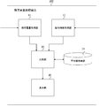
- FIG. 2 shows an example of a functional block diagram of the remaining charge amount comparison device 100 according to the first embodiment.
- the remaining charge amount comparison device 100 includes a remaining charge amount acquisition unit 11, an operation information acquisition unit 12, an average value storage unit 13, a comparison unit 14, and a display unit 15.
- the remaining charge amount acquisition unit 11 receives the information on the remaining charge amount for each time of the battery 102 detected by the SOC sensor 105 via the communication network 103.
- the remaining charge amount acquisition unit 11 receives the position information of the vehicle 101 positioned by the GPS sensor 106 for each time via the communication network 103.
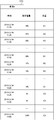
- the remaining charge amount acquisition unit 11 associates the remaining charge amount information of the battery 102 with the position information of the vehicle 101 by the time information to generate the remaining charge amount-position information log 131 for each vehicle 101, and the comparison unit 14 Pass to.
- FIG. 3 shows an example of the remaining charge amount-position information log 131 in the first embodiment.
- the remaining charge amount-position information log 131 is information in which the position information and the remaining charge amount are associated with each time.
- the remaining charge amount-position information log 131 is information generated for each vehicle 101, and is information about "vehicle X" in FIG.
- the remaining charge amount-location information log 131 is generated as a log for each time (for example, every minute) for receiving information from the communication unit 104 of the battery 102, but in FIG. 3, it is simplified as a log for every 5 minutes. There is.
- the remaining charge amount-location information log 131 is generated and transmitted by the remaining charge amount acquisition unit 11 at predetermined time intervals (for example, 1 minute intervals).
- the remaining charge amount-position information log 131 is transmitted from the comparison unit 14 to the average value storage unit 13 and stored in the average value storage unit 13.
- the operation information acquisition unit 12 acquires charging operation information from the charge detection sensor 107 of the vehicle 101 via the communication network 103. When the operation information acquisition unit 12 acquires the charging operation information, it passes it to the comparison unit 14. The operation information acquisition unit 12 transmits the information to the comparison unit 14 every time the charge operation information is received from the charge detection sensor 107, but it may be performed at a predetermined time interval (for example, 1 minute interval).
- the average value storage unit 13 stores information on the average value of the remaining charge amount during the charging operation in the plurality of charging operations.
- FIG. 4 shows an example of the remaining charge amount log 132 including the information of the average value of the remaining charge amount stored in the average value storage unit 13 in the first embodiment.
- the remaining charge amount log 132 the remaining charge amount (%) at the time when the charging operation is detected is recorded.
- the remaining charge amount log 132 is generated in advance and stored in the average value storage unit 13.
- the remaining charge amount log 131 is information generated for each vehicle 101, and in FIG. 4, the remaining charge amount log 132 generated for the vehicle (X) is shown.
- the remaining charge amount log 132 may be information generated for each battery 102, or may be information generated collectively for a plurality of vehicles 101.
- a plurality of remaining charge amounts (%) for the vehicle (X) are recorded in the remaining charge amount log 132 in chronological order, and the lowest line of the remaining charge amount log 132 contains The average value 133 of the plurality of recorded remaining charge amounts is displayed.
- the average value 133 is information indicating the average of the remaining charge amount at the time when the charging operation is performed on the vehicle (X), and is "12%" in FIG.
- the remaining charge amount log 132 is information generated collectively for a plurality of vehicles 101
- the average value 133 indicates the average of the remaining charge amounts at the time when the charging operation is performed for the plurality of vehicles 101. It becomes information.
- the comparison unit 14 includes the remaining charge amount-position information log 131 received from the remaining charge amount acquisition unit 11, the charging operation information received from the operation information acquisition unit 12, and the average value 133 stored in the average value storage unit 13. Therefore, at the time when the charging operation is performed, the result of comparing the remaining charge amount of the battery 102 with the average value stored in the average value storage unit is output to the display unit 15.
- the comparison unit 14 sets the remaining charge amount as "20%” at that time.
- the display unit 15 outputs that the remaining charge amount of the battery 102 is "8%” higher than the average value 133 in comparison with "12%” which is the average value of the remaining charge amount 133.
- the comparison unit 14 has "10%” which is the remaining charge amount at that time and the average value of the remaining charge amount. Compared with "12%” which is 133, it is output to the display unit 15 that the remaining charge amount of the battery 102 is "2%” lower than the average value 133.
- the display unit 15 has information on the remaining charge amount acquired by the remaining charge amount acquisition unit 11 and information on the position corresponding to the remaining charge amount determined by the comparison unit 14 to be lower than the average value 133 by a threshold value. Is displayed on the map in association with the information on the remaining charge amount.
- the threshold value is set to, for example, "2%", but other numerical values may be used. Further, the threshold value may be a value that dynamically fluctuates according to a time zone or the like.
- the display unit 15 provides information on the position corresponding to the remaining charge amount on the map when the remaining charge amount is "10%" or less, which is a value "2%" lower than the average value 133 "12%". Display on. In FIG.
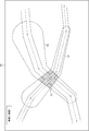
- FIG. 5 shows a traveling locus map 50 of the vehicle X in the first embodiment.
- the traveling locus of the vehicle X and the remaining charge amount associated with the traveling locus are displayed.
- the remaining charge amount of the vehicle X is represented by a circle having a size corresponding to the remaining charge amount centered on the position of the vehicle X. Therefore, on the traveling locus of the vehicle X, a traveling locus region 51, which is an region in which a plurality of circles are overlapped, is displayed.
- the vehicle X is traveling from left to right.
- the larger the remaining charge amount the larger the size of the circle.
- the remaining charge is indicated by a circle with a radius a of a size corresponding to "10%”
- the remaining charge is of a size corresponding to "9%”.
- It is represented by a circle with a radius b ( ⁇ a)
- the residual current collection amount is represented by a circle with a radius c ( ⁇ b) having a size corresponding to "8%”.
- the traveling locus region 51 in FIG. 5 indicates an region in which the vehicle continues to travel even when the threshold value “2%” is lower than the average value of 133 “12%” of the vehicle X. The cause may be that charging could not be performed because there was no charging station nearby.
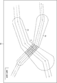
- FIG. 6 shows a traveling locus map 60 of the vehicle Y in the first embodiment.
- the traveling locus of the vehicle Y which is different from the vehicle X, and the remaining charge amount associated with the traveling locus are displayed.
- the remaining charge amount log 132 and the average value 133 are also generated for the vehicle Y, and the average value 133 of the vehicle Y is "22%", which is higher than the average value 133 of the vehicle X, "12%".
- a large example is shown. It is considered that the user of the vehicle Y is more concerned than the user of the vehicle X and is charging at a relatively early stage.
- the display unit 15 shows the vehicle Y corresponding to the remaining charge amount when the remaining charge amount of the vehicle Y is "20%” or less, which is a value lower than the threshold value "2%” than the average value 133 "22%”. Display the location information on the map.
- the positions of the vehicle Y are “D1", “D2", and “D3”, and the remaining charge amount corresponding to each position is “20%”. , “15%”, “10%”.
- a traveling locus region 61 which is an region in which a plurality of circles are overlapped, is displayed.
- the remaining charge amount is displayed by a circle with a radius d of a size corresponding to "20%", and at the point "D2", the remaining charge amount is "15%”.
- the amount of residual electricity is displayed by a circle with a radius f ( ⁇ e) of a size corresponding to "10%”.
- the vehicle Y is traveling from right to left.
- FIG. 7 shows a travel locus map 70 in which the travel locus maps of the vehicle X and the vehicle Y in the first embodiment are superimposed.
- the display unit 15 creates and displays a map 70 by superimposing the travel locus map 50 of the vehicle X shown in FIG. 5 and the travel locus map 60 of the vehicle Y shown in FIG.
- FIG. 7 shows a region 71 in which the travel locus region 51 of the vehicle X and the travel locus region 61 of the vehicle Y overlap.
- the area 71 indicates an area in which it is considered that the users of the vehicle X and the vehicle Y both want to charge the battery 102 but cannot charge the battery 102. That is, the area 71 is an area in which both the users of the vehicle X and the vehicle Y are considered to have wanted to charge, and the demand for the charging station is expected to be higher.
- the display unit 15 creates a travel locus map for each of the plurality of vehicles 101, superimposes the created travel locus maps, and displays an area where the demand for the charging station is high on the map. For example, the display unit 15 displays the number of times (numbers) of overlapping within a predetermined range at the height of the bar graph for each range. It is expected that the demand for charging stations will increase as the number of times (number) of superpositions increases.
- the predetermined range may be determined in units of cities, towns and villages, by address, or within a certain distance (for example, 1 km) from a specific point. May be good.
- FIG. 8 shows the demand for charging stations for each range in the first embodiment.
- the number of times the traveling locus regions of the plurality of vehicles 101 are overlapped is displayed by the height of the bar graph for each range.
- F1 to F5 in FIG. 8 indicate a guideline for the number of times the traveling locus regions are overlapped.
- F5 the number of times the traveling locus regions are overlapped is larger than in F1.
- the area 81 and the area 82 are candidates for installing a new charging station.
- the remaining charge amount comparison device 100 As described above, according to the remaining charge amount comparison device 100 according to the first embodiment, the remaining charge amount and the average value 133 of the battery 102 at the time when the charging operation of the battery 102 of the specific vehicle 101 is detected. And output. As a result, the user of the remaining charge amount comparison device 100 determines whether the charging operation in the vehicle 101 is performed at a timing when the remaining charge amount is smaller than usual or at a timing when the remaining charge amount is larger than usual. Can be grasped.
- the display unit 15 superimposes the travel locus maps of the plurality of vehicles 101 and displays the area where the demand for the charging station is high on the map.
- the user of the remaining charge amount comparison device 100 can grasp the area where the demand for the charging station is expected to be high, and can grasp the place which is a candidate for installing a new charging station.
- FIG. 9 shows a superposed traveling locus map 80 in the modified example.
- FIG. 9 shows a case where the remaining charge amount of the vehicle 101 is displayed as a circle having a size substantially inversely proportional to the remaining charge amount.
- the region at the position where the remaining charge amount is small is larger than the region at the position where the remaining charge amount is large. It can be displayed in a large size, and the display can more accurately reflect the degree to which the user desires to charge.
- the display unit 15 displays the number of times the traveling locus regions are overlapped at the height of the bar graph for each range.
- the display unit 15 may display by changing the hatching density for each range according to the number of times of superposition.
- an area where hatching is concentrated is an area where demand for a charging station is expected to be high, and is a candidate place for installing a new charging station.
- FIG. 10 shows an example of the operating environment of the remaining charge amount comparison device 200 according to the second embodiment.
- the vehicle 101 further includes a user identification sensor 108 that identifies the user of the vehicle 101. Since the other elements of the operating environment in the second embodiment are the same as those in the operating environment in the first embodiment, the same reference numerals are given and the description thereof will be omitted.
- the user identification sensor 108 identifies the user who drives the vehicle 101.
- the user identification sensor 108 includes, for example, an in-vehicle camera that photographs the driver's seat of the vehicle 101, and pattern collates the photographed image of the driver's seat taken by the in-vehicle camera with the image stored in advance in the memory of the user identification sensor 108. By doing so, the user who drives the vehicle 101 is identified.
- the user identification sensor 108 transmits the user identification information, which is information about the identified user, to the communication unit 104 of the battery 102.
- the communication unit 104 associates the information received from the SOC sensor 105, the GPS sensor 106, and the charge detection sensor 107 with the user identification information, and transmits the remaining charge amount comparison device 100.
- the user identification information includes, for example, information such as the age, address, and gender of the user.
- FIG. 11 shows an example of a functional block diagram of the remaining charge amount comparison device 200 according to the second embodiment.
- the remaining charge amount comparison device 200 according to the second embodiment includes an average value calculation unit 16 in addition to the components of the remaining charge amount comparison device 100 according to the first embodiment. Since the other components of the remaining charge amount comparison device 200 in the second embodiment are the same as those in the remaining charge amount comparison device 100 in the first embodiment, the same reference numerals are given and the description thereof will be omitted.
- the remaining charge amount acquisition unit 11 associates the remaining charge amount information of the battery 102 associated with the user identification information with the position information of the vehicle 101 by the time information, and the remaining charge amount-position information log 231 for each user.
- FIG. 12 shows an example of the remaining charge amount-position information log 231 in the second embodiment. As shown in FIG. 12, the remaining charge amount-position information log 231 is information generated for the user X1.
- the average value calculation unit 16 generates a remaining charge amount log for each user from the remaining charge amount-position information log 231 for each user and the charging operation information, and the average value of the remaining charge amount during the charging operation for each user. Is calculated.
- FIG. 13 shows an example of the remaining charge amount log 232 according to the second embodiment.
- the remaining charge amount log 232 is information generated for each user. In FIG. 13, the remaining charge amount log 232 and the average value 233 generated for the user X1 are shown.
- the comparison unit 14 charges from the remaining charge amount-position information log 231 for each user received from the remaining charge amount acquisition unit 11, the charging operation information received from the operation information acquisition unit 12, and the average value 233 for each user. At the time when the operation is performed, the result of comparing the remaining charge amount of the battery 102 and the average value 233 for the user is output to the display unit 15.
- the display unit 15 creates a travel locus map for each of the plurality of users based on the information received from the comparison unit 14.
- the display unit 15 classifies the created plurality of travel locus maps according to the type of user.
- the display unit 15 classifies and superimposes a plurality of travel locus maps for each age of the user, for example.
- FIG. 14 shows the demand for charging stations for each range in the second embodiment.
- FIG. 14 shows the demand for a charging station created by superimposing a travel locus map of a user in his twenties.
- the display unit 15 may perform the above classification according to the gender of the user, or may perform the above classification according to the area to which the user's address belongs (for example, by municipality).
- the remaining charge amount comparison device 200 As described above, according to the remaining charge amount comparison device 200 according to the second embodiment, the remaining charge amount and the average value 133 of the battery 102 at the time when the charging operation of the battery 102 of a specific user is detected. Is compared and output. As a result, the user of the remaining charge amount comparison device 100 can determine whether the charging operation by the specific user is performed at the timing when the remaining charge amount is smaller than usual or at the timing when the remaining charge amount is larger than usual. Can be grasped.
- the display unit 15 superimposes a plurality of travel locus maps for each user type, and sets a region where the demand for the charging station is high for each user type. Display on the map.
- the user of the remaining charge amount comparison device 100 can grasp the area where the demand for the charging station is expected to be high for each type of user, and install a new charging station according to the type of user. You can grasp the candidate location.
- Dedicated circuits may include digital and / or analog hardware circuits, and may include integrated circuits (ICs) and / or discrete circuits.
- Programmable circuits are memory elements such as logical AND, logical OR, logical XOR, logical NAND, logical NOR, and other logical operations, flip-flops, registers, field programmable gate arrays (FPGA), programmable logic arrays (PLA), etc. May include reconfigurable hardware circuits, including.
- the computer-readable medium may include any tangible device capable of storing instructions executed by the appropriate device, so that the computer-readable medium having the instructions stored therein is specified in a flowchart or block diagram. It will be equipped with a product that contains instructions that can be executed to create means for performing the operation. Examples of computer-readable media may include electronic storage media, magnetic storage media, optical storage media, electromagnetic storage media, semiconductor storage media, and the like.
- Computer-readable media include floppy (registered trademark) disks, diskettes, hard disks, random access memory (RAM), read-only memory (ROM), erasable programmable read-only memory (EPROM or flash memory), Electrically erasable programmable read-only memory (EEPROM), static random access memory (SRAM), compact disk read-only memory (CD-ROM), digital versatile disc (DVD), Blu-ray (RTM) disc, memory stick, integrated A circuit card or the like may be included.
- RAM random access memory
- ROM read-only memory
- EPROM or flash memory erasable programmable read-only memory
- EEPROM Electrically erasable programmable read-only memory
- SRAM static random access memory
- CD-ROM compact disk read-only memory
- DVD digital versatile disc
- Blu-ray (RTM) disc memory stick, integrated A circuit card or the like may be included.
- Computer-readable instructions are assembler instructions, instruction set architecture (ISA) instructions, machine instructions, machine-dependent instructions, microcode, firmware instructions, state-setting data, or object-oriented programming such as Smalltalk, JAVA®, C ++, etc. Contains either source code or object code written in any combination of one or more programming languages, including languages and traditional procedural programming languages such as the "C" programming language or similar programming languages. Good.
- Computer-readable instructions are applied locally or to a processor or programmable circuit of a general purpose computer, special purpose computer, or other programmable data processing device, or to a wide area network (WAN) such as the local area network (LAN), the Internet, etc. ) May be executed to create a means for performing the operation specified in the flowchart or block diagram.
- processors include computer processors, processing units, microprocessors, digital signal processors, controllers, microcontrollers and the like.
- FIG. 15 shows an example of a computer 2200 in which a plurality of aspects of the present invention may be embodied in whole or in part.
- the program installed on the computer 2200 can cause the computer 2200 to function as an operation or one or more sections of the device according to an embodiment of the invention, or the operation or the one or more. Sections can be run and / or the computer 2200 can be run a process according to an embodiment of the invention or a stage of such process.
- Such a program may be run by the CPU 2212 to cause the computer 2200 to perform certain operations associated with some or all of the blocks of the flowcharts and block diagrams described herein.
- the computer 2200 includes a CPU 2212, a RAM 2214, a graphic controller 2216, and a display device 2218, which are connected to each other by a host controller 2210.
- the computer 2200 also includes input / output units such as a communication interface 2222, a hard disk drive 2224, a DVD-ROM drive 2226, and an IC card drive, which are connected to the host controller 2210 via the input / output controller 2220.
- input / output units such as a communication interface 2222, a hard disk drive 2224, a DVD-ROM drive 2226, and an IC card drive, which are connected to the host controller 2210 via the input / output controller 2220.
- the computer also includes legacy input / output units such as ROM 2230 and keyboard 2242, which are connected to the input / output controller 2220 via an input / output chip 2240.
- the CPU 2212 operates according to the programs stored in the ROM 2230 and the RAM 2214, thereby controlling each unit.
- the graphic controller 2216 acquires the image data generated by the CPU 2212 in a frame buffer or the like provided in the RAM 2214 or itself so that the image data is displayed on the display device 2218.
- the communication interface 2222 communicates with other electronic devices via the network.
- the hard disk drive 2224 stores programs and data used by the CPU 2212 in the computer 2200.
- the DVD-ROM drive 2226 reads the program or data from the DVD-ROM 2201 and provides the program or data to the hard disk drive 2224 via the RAM 2214.
- the IC card drive reads programs and data from the IC card and / or writes programs and data to the IC card.
- the ROM 2230 stores a boot program or the like executed by the computer 2200 at the time of activation and / or a program depending on the hardware of the computer 2200.
- the input / output chip 2240 may also connect various input / output units to the input / output controller 2220 via a parallel port, serial port, keyboard port, mouse port, and the like.
- the program is provided by a computer-readable medium such as a DVD-ROM 2201 or an IC card.
- the program is read from a computer-readable medium, installed on a hard disk drive 2224, RAM 2214, or ROM 2230, which is also an example of a computer-readable medium, and executed by the CPU 2212.
- the information processing described in these programs is read by the computer 2200 and provides a link between the program and the various types of hardware resources described above.
- the device or method may be configured to perform manipulation or processing of information in accordance with the use of computer 2200.
- the CPU 2212 executes a communication program loaded in the RAM 2214, and performs communication processing on the communication interface 2222 based on the processing described in the communication program. You may order.
- the communication interface 2222 reads and reads the transmission data stored in the transmission buffer processing area provided in the recording medium such as the RAM 2214, the hard disk drive 2224, the DVD-ROM 2201, or the IC card. The data is transmitted to the network, or the received data received from the network is written to the reception buffer processing area or the like provided on the recording medium.
- the CPU 2212 causes the RAM 2214 to read all or necessary parts of a file or database stored in an external recording medium such as a hard disk drive 2224, a DVD-ROM drive 2226 (DVD-ROM2201), or an IC card. Various types of processing may be performed on the data on the RAM 2214. The CPU 2212 then writes back the processed data to an external recording medium.
- an external recording medium such as a hard disk drive 2224, a DVD-ROM drive 2226 (DVD-ROM2201), or an IC card.
- Various types of processing may be performed on the data on the RAM 2214.
- the CPU 2212 then writes back the processed data to an external recording medium.
- the CPU 2212 describes various types of operations, information processing, conditional judgment, conditional branching, unconditional branching, and information retrieval described in various parts of the present disclosure with respect to the data read from the RAM 2214, and is specified by the instruction sequence of the program. Various types of processing may be performed, including / replacement, etc., and the results are written back to RAM 2214. Further, the CPU 2212 may search for information in a file, a database, or the like in the recording medium. For example, when a plurality of entries each having an attribute value of the first attribute associated with the attribute value of the second attribute are stored in the recording medium, the CPU 2212 specifies the attribute value of the first attribute. Search for an entry that matches the condition from the plurality of entries, read the attribute value of the second attribute stored in the entry, and associate it with the first attribute that satisfies the predetermined condition. The attribute value of the second attribute obtained may be acquired.
- the program or software module described above may be stored on a computer 2200 or on a computer-readable medium near the computer 2200.
- a recording medium such as a hard disk or RAM provided within a dedicated communication network or a server system connected to the Internet can be used as a computer-readable medium, thereby providing the program to the computer 2200 over the network. To do.
Landscapes
- Engineering & Computer Science (AREA)
- Power Engineering (AREA)
- Business, Economics & Management (AREA)
- Mechanical Engineering (AREA)
- Transportation (AREA)
- Human Resources & Organizations (AREA)
- Strategic Management (AREA)
- Economics (AREA)
- Marketing (AREA)
- Entrepreneurship & Innovation (AREA)
- Tourism & Hospitality (AREA)
- Physics & Mathematics (AREA)
- General Business, Economics & Management (AREA)
- General Physics & Mathematics (AREA)
- Theoretical Computer Science (AREA)
- Operations Research (AREA)
- Health & Medical Sciences (AREA)
- Development Economics (AREA)
- Game Theory and Decision Science (AREA)
- Primary Health Care (AREA)
- Quality & Reliability (AREA)
- General Health & Medical Sciences (AREA)
- Educational Administration (AREA)
- Life Sciences & Earth Sciences (AREA)
- Sustainable Development (AREA)
- Sustainable Energy (AREA)
- Electric Propulsion And Braking For Vehicles (AREA)
- Charge And Discharge Circuits For Batteries Or The Like (AREA)
- Management, Administration, Business Operations System, And Electronic Commerce (AREA)
- Secondary Cells (AREA)
Abstract
残充電量比較装置は、電気で駆動する車両に搭載されるバッテリの残充電量の情報を取得する残充電量取得部と、バッテリへの充電動作がなされた情報を取得する動作情報取得部と、複数回の充電動作における充電動作時の残充電量の平均値の情報を格納する平均値格納部と、動作情報取得部でバッテリへの充電動作が検出された場合に、バッテリの残充電量と平均値格納部に格納された平均値と比較した結果を出力する比較部と、を備える。
Description
本発明は、残充電量比較装置、残充電量比較方法、および残充電量比較プログラムに関する。
充電ステーションの位置などを考慮して、目的地に到達するまでに車両が必要とする電力を予測することが行われている(例えば、特許文献1参照)。
[先行技術文献]
[特許文献]
[特許文献1] 特開2012-113546
[先行技術文献]
[特許文献]
[特許文献1] 特開2012-113546
本発明の一態様においては、残充電量比較装置が提供される。残充電量比較装置は、電気で駆動する車両に搭載されるバッテリの残充電量の情報を取得する残充電量取得部を備えてもよい。残充電量比較装置は、バッテリへの充電動作がなされた情報を取得する動作情報取得部を備えてもよい。残充電量比較装置は、複数回の充電動作における充電動作時の残充電量の平均値の情報を格納する平均値格納部を備えてもよい。残充電量比較装置は、動作情報取得部でバッテリへの充電動作が検出された場合に、バッテリの残充電量と平均値格納部に格納された平均値と比較した結果を出力する比較部を備えてもよい。
残充電量取得部は、残充電量の情報と車両の位置の情報を対応付けて取得し、残充電量取得部が取得した残充電量の情報および位置の情報のうち、比較部が平均値よりも閾値分下回ったと判断した残充電量に対応する位置の情報を、残充電量の情報に対応付けて表示する表示部をさらに備えてもよい。
表示部は、地図を表示するとともに、位置の情報に対応する残充電量の情報を地図における位置に表示してもよい。
表示部は、残充電量の情報を残充電量の大きさに対応した大きさで表示してもよい。
表示部は、残充電量の情報を残充電量が小さいほど大きくした円で表示してもよい。
表示部は、複数の残充電量の情報を重ねて表示してもよい。
表示部は、表示された複数の残充電量の情報の、予め定められた範囲内における数と、位置とを対応付けて表示してもよい。
残充電量取得部は、残充電量に対応付けて車両に搭乗するユーザを識別するユーザ識別情報を取得し、表示部は、ユーザ識別情報で識別されるユーザごとに残充電量を表示してもよい。
ユーザ識別情報で識別されるユーザごとに充電動作時の残充電量の平均値を算出して平均値格納部に格納する平均値算出部をさらに備え、比較部は、ユーザ識別情報で識別されるユーザに対応した平均値と残充電量とを比較してもよい。
残充電量取得部は、残充電量の情報と時刻の情報を対応付けて取得し、表示部は、時刻ごとに残充電量を表示してもよい。
本発明の一態様においては、残充電量比較方法が提供される。残充電量比較方法は、電気で駆動する車両に搭載されるバッテリの残充電量の情報を取得する残充電量取得段階を備えてもよい。残充電量比較方法は、バッテリへの充電動作がなされた情報を取得する動作情報取得段階を備えてもよい。残充電量比較方法は、複数回の充電動作における充電動作時の残充電量の平均値の情報を格納する平均値格納段階を備えてもよい。残充電量比較方法は、動作情報取得部でバッテリへの充電動作が検出された場合に、バッテリの残充電量と平均値格納段階で格納された平均値と比較した結果を出力する比較段階を備えてもよい。
本発明の一態様においては、コンピュータに上記の決定方法を実行させるためのプログラムが提供される。
なお、上記の発明の概要は、本発明の必要な特徴の全てを列挙したものではない。また、これらの特徴群のサブコンビネーションもまた、発明となりうる。
以下、発明の実施の形態を通じて本発明を説明するが、以下の実施形態は請求の範囲にかかる発明を限定するものではない。また、実施形態の中で説明されている特徴の組み合わせの全てが発明の解決手段に必須であるとは限らない。
[第1の実施形態]
図1は、第1の実施形態における残充電量比較装置100の動作環境の一例を示す。車両101にはバッテリ102が搭載されており、バッテリ102は無線通信機能を有する通信部104を備える。残充電量比較装置100は、通信ネットワーク103を介して、車両101に搭載されたバッテリ102の通信部104と通信を行う。
図1は、第1の実施形態における残充電量比較装置100の動作環境の一例を示す。車両101にはバッテリ102が搭載されており、バッテリ102は無線通信機能を有する通信部104を備える。残充電量比較装置100は、通信ネットワーク103を介して、車両101に搭載されたバッテリ102の通信部104と通信を行う。
車両101は、電気で駆動する車両である。図1においては、車両101が4輪自動車である例が示されているが、車両101は2輪自動車(いわゆるバイク)であってもよい。車両101は、電気モーターのみで走行する電気自動車(EV:Electric Vehicle)であってもよく、車内で発電する燃料電池車(FCV:Fuel Cell Vehicl)であってもよく、エンジンとモーターを使い分けながら走行するハイブリッドカー(HV:Hybrid Vehicle)であってもよく、外部から充電が可能なプラグインハイブリッドカー(PHEV・PHV:Plug-in Hybrid Vehicle)であってもよい。
車両101は、SOC(State of Charge)センサ105、GPS(Global Positioning System)センサ106、充電検知センサ107を備える。SOCセンサ105は、車両101のバッテリ102の残充電量であるSOCを取得するセンサであり、電流センサ、電圧センサ、および温度センサ等により構成される。SOCセンサ105は、バッテリ102の残充電量を検出すると、検出した残充電量を時刻情報に紐付けてバッテリ102の通信部104に渡す。SOCセンサ105によるバッテリ102の残充電量を検出は、所定の時間間隔(例えば1分間隔)で行われる。なお、時刻には年月日も含まれる。
GPSセンサ106は、車両101の位置を検出する。GPSセンサ106は、GPS衛星信号を受信し、車両101の位置情報(緯度及び経度)を測位する。GPSセンサ106は、測位した車両101の位置情報を、時刻情報に紐付けてバッテリ102の通信部104に渡す。GPSセンサ106による測位は、所定の時間間隔(例えば1分間隔)で行われる。
充電検知センサ107は、例えば、バッテリ102への充電用プラグの挿入を検知する検知回路を有しており、充電用プラグの挿入を検知することにより、バッテリ102への充電動作を検知する。充電検知センサ107は、バッテリ102への充電動作を検知すると、充電動作が行われたとの充電動作情報を、時刻情報に紐付けてバッテリ102の通信部104に渡す。
バッテリ102は、車両101に搭載されるバッテリである。バッテリ102は、例えば、リチウムイオン電池である。バッテリ102は、例えば、車両101の外部から充電プラグ等を差し込むことにより充電される。バッテリ102は、車両101に対して着脱可能なバッテリであって、充電ステーションで交換されるものであってもよい。
バッテリ102の通信部104は、SOCセンサ105、GPSセンサ106、および充電検知センサ107から受信した情報を、車両ID等の車両101の識別情報に紐付けて通信ネットワーク103を経由して残充電量比較装置100に渡す。通信部104による情報の送信は、所定の時間間隔(例えば1分間隔)で行われる。
なお、バッテリ102は、SOCセンサ105、GPSセンサ106、および充電検知センサ107から受信した情報を記録するメモリを有しており、充電検知センサ107から充電動作情報を受信したタイミングでまとめて情報の送信が行われてもよい。また、通信部104は、SOCセンサ105、GPSセンサ106、および充電検知センサ107から受信した情報を、バッテリID等のバッテリ102の識別情報に紐付けて残充電量比較装置100に送信してもよい。
図2は、第1の実施形態における残充電量比較装置100の機能ブロック図の一例を示す。図2に示すように、残充電量比較装置100は、残充電量取得部11と、動作情報取得部12と、平均値格納部13と、比較部14と、表示部15と、を備える。
残充電量取得部11は、SOCセンサ105が検出したバッテリ102の時刻ごとの残充電量の情報を、通信ネットワーク103を介して受信する。残充電量取得部11は、GPSセンサ106が測位した車両101の時刻ごとの位置情報を、通信ネットワーク103を介して受信する。残充電量取得部11は、バッテリ102の残充電量の情報と車両101の位置情報とを時刻情報により対応付けて、車両101ごとの残充電量-位置情報ログ131を生成し、比較部14に渡す。
図3は、第1の実施形態における残充電量-位置情報ログ131の一例を示す。残充電量-位置情報ログ131は、時刻ごとに位置情報と残充電量とが対応付けられた情報である。残充電量-位置情報ログ131は、車両101ごとに生成された情報であり、図3においては「車両X」についての情報である。なお、残充電量-位置情報ログ131は、バッテリ102の通信部104から情報を受け取る時間ごと(例えば1分ごと)のログとして生成されるが、図3では簡略化して5分刻みのログとしている。
図3に示すように、例えば、時刻「2019/2/14 11:20」において、残充電量は「30%」であり、位置は「地点A1」であるが、時刻「2019/2/14 12:20」において、残充電量は「20%」に減少しており、位置は「地点B1」に移動している。また、時刻「2019/2/14 13:30」において、位置「C3」で充電が行われたため、残充電量が「8%」から「100%」に増加している。
残充電量取得部11による残充電量-位置情報ログ131の生成および送信は、所定の時間間隔(例えば1分間隔)で行われる。残充電量-位置情報ログ131は、比較部14から平均値格納部13に送信され、平均値格納部13に格納される。
動作情報取得部12は、通信ネットワーク103を介して車両101の充電検知センサ107から、充電動作情報を取得する。動作情報取得部12は、充電動作情報を取得すると、比較部14に渡す。動作情報取得部12による比較部14への情報の送信は、充電検知センサ107から充電動作情報を受信する度に行われるが、所定の時間間隔(例えば1分間隔)で行われてもよい。
平均値格納部13は、複数回の充電動作における充電動作時の残充電量の平均値の情報を格納する。図4は、第1の実施形態における平均値格納部13に格納された残充電量の平均値の情報を含む残充電量ログ132の一例を示す。残充電量ログ132には、充電動作が検知された時刻における残充電量(%)が記録される。残充電量ログ132は、予め生成され、平均値格納部13に格納されている。残充電量ログ131は、車両101ごとに生成された情報であり、図4においては、車両(X)について生成された残充電量ログ132が示されている。なお、残充電量ログ132は、バッテリ102ごとに生成された情報であってもよく、複数の車両101についてまとめて生成された情報であってもよい。
図4に示すように、残充電量ログ132には、車両(X)についての複数の残充電量(%)が時刻順に記録されており、残充電量ログ132の最下位の行には、記録された複数の残充電量の平均値133が表示されている。平均値133は、車両(X)について充電動作が行われる時点での残充電量の平均を示す情報であり、図4においては「12%」である。なお、残充電量ログ132が複数の車両101についてまとめて生成された情報である場合には、平均値133は、複数の車両101について充電動作が行われる時点での残充電量の平均を示す情報となる。
比較部14は、残充電量取得部11から受け取った残充電量-位置情報ログ131と、動作情報取得部12から受け取った充電動作情報と、平均値格納部13に格納された平均値133とから、充電動作が行われた時刻において、バッテリ102の残充電量と平均値格納部に格納された平均値と比較した結果を表示部15に出力する。
例えば、図3に示す例において、充電動作が行われた時刻が「2019/2/14 12:20」であるとき、比較部14は、当該時刻における残充電量である「20%」と、残充電量の平均値133である「12%」とを比較して、バッテリ102の残充電量が平均値133より「8%」高いことを表示部15に出力する。一方で、充電動作が行われた時刻が「2019/2/14 13:20」であるとき、比較部14は、当該時刻における残充電量である「10%」と、残充電量の平均値133である「12%」とを比較して、バッテリ102の残充電量が平均値133より「2%」低いことを表示部15に出力する。
表示部15は、残充電量取得部11が取得した残充電量の情報および位置の情報のうち、比較部14が平均値133よりも閾値分下回ったと判断した残充電量に対応する位置の情報を、残充電量の情報に対応付けて地図上に表示する。ここで、閾値を、例えば「2%」とするが、他の数値としてもよい。また、閾値は時間帯などに応じて動的に変動する値であってもよい。表示部15は、残充電量が平均値133の「12%」よりも「2%」下回った値である「10%」以下である場合の、残充電量に対応する位置の情報を地図上に表示する。図3において、残充電量が「10%」以下である場合の、車両Xの位置は「C1」、「C2」、「C3」であり、それぞれの位置に対応する残充電量は、「10%」、「9%」、「8%」である。
図5は、第1の実施形態における車両Xの走行軌跡マップ50を示す。図5には、車両Xの走行軌跡と、走行軌跡に対応付けられた残充電量とが表示されている。図5において、車両Xの残充電量は、車両Xの位置を中心とし、残充電量に対応する大きさの円で表示されている。したがって、車両Xの走行軌跡上には、複数の円が重ね合わされた領域である走行軌跡領域51が表示されている。なお、図5において、車両Xは左から右に向かって走行している。
図5の例において、残充電量が大きいほど円の大きさも大きい。地点「C1」において、残充電量は「10%」に対応する大きさの半径aの円で表示されており、地点「C2」において、残充電量は「9%」に対応する大きさの半径b(<a)の円で表示されており、地点「C3」において、残集電量は「8%」に対応する大きさの半径c(<b)の円で表示されている。図5における走行軌跡領域51は、車両Xの平均値133である「12%」より閾値「2%」下回った状態になっても走行を続けている領域を示す。その原因としては、近くに充電ステーションがなかったため充電を行えなかったなどが考えられる。
図6は、第1の実施形態における車両Yの走行軌跡マップ60を示す。図6には、車両Xとは異なる車両Yの走行軌跡と、走行軌跡に対応付けられた残充電量とが表示される。ここで、車両Yについても残充電量ログ132および平均値133が生成されており、車両Yの平均値133は「22%」であり、車両Xの平均値133である「12%」よりも大きい例が示されている。これは、車両Yのユーザは、車両Xのユーザと比べて心配性であり、比較的早い段階で充電を行っているものと考えられる。
表示部15は、車両Yの残充電量が平均値133の「22%」よりも閾値「2%」下回った値である「20%」以下である場合の、残充電量に対応する車両Yの位置の情報を地図上に表示する。なお、残充電量が「20%」以下である場合の、車両Yの位置は「D1」、「D2」、「D3」であり、それぞれの位置に対応する残充電量は、「20%」、「15%」、「10%」であるものとする。
図6における車両Yの走行軌跡上には、複数の円が重ね合わされた領域である走行軌跡領域61が表示されている。図6に示すように、地点「D1」において、残充電量は「20%」に対応する大きさの半径dの円で表示されており、地点「D2」において、残充電量は「15%」に対応する大きさの半径e(<d)の円で表示されており地点「D3」において、残集電量は「10%」に対応する大きさの半径f(<e)の円で表示されている。なお、図6において車両Yは右から左に向かって走行している。
図7は、第1の実施形態における車両Xと車両Yの走行軌跡マップを重ね合わせた走行軌跡マップ70を示す。表示部15は、図5に示される車両Xの走行軌跡マップ50と、図6に示される車両Yの走行軌跡マップ60とを重ね合わせてマップ70を作成し、表示する。図7には、車両Xの走行軌跡領域51と車両Yの走行軌跡領域61とが重なる領域である領域71が示されている。領域71は、車両Xおよび車両Yのユーザが共にバッテリ102の充電を行いたいのに、充電を行えなかったと考えられる領域を示している。すなわち、領域71は、車両Xと車両Yのユーザの双方が充電したかったと考えられる領域であり、充電ステーションの需要がより見込まれる領域である。
表示部15は、複数の車両101についてそれぞれ走行軌跡マップを作成し、作成した複数の走行軌跡マップを重ね合わせて、充電ステーションの需要が高い領域を地図上に表示する。例えば、表示部15は、予め定められた範囲内における重ねあわされた回数(数)を範囲ごとの棒グラフの高さで表示する。重ね合された回数(数)が多い範囲ほど、充電ステーションの需要が高いことが見込まれる。なお、予め定められた範囲内とは、例えば市町村単位で定められてもよく、番地単位で定められてもよく、あるいは、特定の地点から一定の距離(例えば1km)の範囲内として予め定めてもよい。
図8は、実施の形態1における範囲ごとの充電ステーションの需要を示す。図8には、複数の車両101の走行軌跡領域が重ねあわされた回数が、範囲ごとに棒グラフの高さで表示されている。図8におけるF1からF5は、走行軌跡領域が重ねあわされた回数の目安を示している。F1よりもF5の方が、走行軌跡領域が重ねあわされた回数が多い。図8に示すように、領域81と領域82は、他の領域に比べて棒グラフの高さが相対的に高いため、充電ステーションの需要が高いことが分かる。したがって、領域81と領域82は、新たな充電ステーション設置の候補となる場所である。
以上のように、第1の実施形態に係る残充電量比較装置100によれば、特定の車両101のバッテリ102への充電動作が検出された時刻における、バッテリ102の残充電量と平均値133とを比較して出力する。これにより、残充電量比較装置100の使用者が、当該車両101における充電動作が、通常よりも残充電量が少ないタイミングで行われたか、通常よりも残充電量が多いタイミングで行われたかを把握することができる。
第1の実施形態に係る残充電量比較装置100によれば、表示部15は、複数の車両101の走行軌跡マップを重ね合わせて、充電ステーションの需要が高い領域を地図上に表示する。これにより、残充電量比較装置100の使用者が、充電ステーションの需要が高いことが見込まれる領域を把握することができ、新たな充電ステーションの設置候補となる場所を把握することができる。
[変形例1]
上記第1の実施形態では、図5から図7に示される走行軌跡マップにおいて、車両101の残充電量が大きいほど円の大きさも大きいが、これに限られない。残充電量が小さいほど円の大きさを大きくしてもよい。図9は、変形例における重ね合わせた走行軌跡マップ80を示す。図9には、車両101の残充電量が、残充電量に概ね反比例する大きさの円で表示された場合について示される。図9のように、車両101の残充電量を、残充電量に反比例する大きさの円で表示することにより、残充電量が少ない位置における領域を、残充電量が多い位置における領域よりも大きく表示することができ、ユーザが充電を希望している度合いをより正確に反映させた表示とすることができる。
上記第1の実施形態では、図5から図7に示される走行軌跡マップにおいて、車両101の残充電量が大きいほど円の大きさも大きいが、これに限られない。残充電量が小さいほど円の大きさを大きくしてもよい。図9は、変形例における重ね合わせた走行軌跡マップ80を示す。図9には、車両101の残充電量が、残充電量に概ね反比例する大きさの円で表示された場合について示される。図9のように、車両101の残充電量を、残充電量に反比例する大きさの円で表示することにより、残充電量が少ない位置における領域を、残充電量が多い位置における領域よりも大きく表示することができ、ユーザが充電を希望している度合いをより正確に反映させた表示とすることができる。
[変形例2]
上記第1の実施形態では、図8に示すように、表示部15は走行軌跡領域が重ねあわされた回数が、範囲ごとに棒グラフの高さで表示するものとした。しかしながら、表示部15は、重ね合された回数に応じて範囲ごとのハッチングの濃さを変えて表示してもよい。この場合には、例えばハッチングが濃い領域が充電ステーションの需要が高いことが見込まれる領域であり、新たな充電ステーション設置の候補となる場所である。
上記第1の実施形態では、図8に示すように、表示部15は走行軌跡領域が重ねあわされた回数が、範囲ごとに棒グラフの高さで表示するものとした。しかしながら、表示部15は、重ね合された回数に応じて範囲ごとのハッチングの濃さを変えて表示してもよい。この場合には、例えばハッチングが濃い領域が充電ステーションの需要が高いことが見込まれる領域であり、新たな充電ステーション設置の候補となる場所である。
[第2の実施形態]
図10は、第2の実施形態における残充電量比較装置200の動作環境の一例を示す。第2の実施形態において、車両101は、車両101のユーザを識別するユーザ識別センサ108をさらに備える。第2の実施形態における動作環境の他の要素は第1の実施形態における動作環境と同じであるため、同じ符号を付して説明を省略する。
図10は、第2の実施形態における残充電量比較装置200の動作環境の一例を示す。第2の実施形態において、車両101は、車両101のユーザを識別するユーザ識別センサ108をさらに備える。第2の実施形態における動作環境の他の要素は第1の実施形態における動作環境と同じであるため、同じ符号を付して説明を省略する。
ユーザ識別センサ108は、車両101の運転を行うユーザを識別する。ユーザ識別センサ108は、例えば、車両101の運転席を撮影する車載カメラを含み、車載カメラにより撮影された運転席の撮影画像と、ユーザ識別センサ108のメモリに予め記憶された画像とをパターン照合することにより、車両101の運転を行うユーザを識別する。
ユーザ識別センサ108は、識別されたユーザに関する情報であるユーザ識別情報をバッテリ102の通信部104に対して送信する。通信部104は、SOCセンサ105、GPSセンサ106、および充電検知センサ107から受信した情報を、ユーザ識別情報に紐付けて残充電量比較装置100に送信する。ユーザ識別情報には、例えば、ユーザの年齢、住所、性別等の情報が含まれる。
図11は、第2の実施形態における残充電量比較装置200の機能ブロック図の一例を示す。第2の実施形態における残充電量比較装置200は、第1の実施形態における残充電量比較装置100の構成要素に加えて、平均値算出部16を備える。第2の実施形態における残充電量比較装置200の他の構成要素は第1の実施形態における残充電量比較装置100と同じであるため、同じ符号を付して説明を省略する。
残充電量取得部11は、ユーザ識別情報に紐付けられたバッテリ102の残充電量の情報と車両101の位置情報とを時刻情報により対応付けて、ユーザごとの残充電量-位置情報ログ231を生成する。図12は、第2の実施形態における残充電量-位置情報ログ231の一例を示す。図12に示すように、残充電量-位置情報ログ231はユーザX1について生成された情報である。
平均値算出部16は、ユーザごとの残充電量-位置情報ログ231と、充電動作情報とから、ユーザごとの残充電量ログを生成し、ユーザごとの充電動作時の残充電量の平均値を算出する。図13は、第2の実施形態における残充電量ログ232の一例を示す。残充電量ログ232は、ユーザごとに生成された情報である。図13においては、ユーザX1について生成された残充電量ログ232及び平均値233が示されている。
比較部14は、残充電量取得部11から受け取ったユーザごとの残充電量-位置情報ログ231と、動作情報取得部12から受け取った充電動作情報と、ユーザごとの平均値233とから、充電動作が行われた時刻において、バッテリ102の残充電量と平均値233とを当該ユーザについて比較した結果を表示部15に出力する。
表示部15は、比較部14から受け取った情報に基づいて、複数のユーザについてそれぞれ走行軌跡マップを作成する。表示部15は、作成した複数の走行軌跡マップについて、ユーザの種別ごとに分類する。表示部15は、例えば、ユーザの年代ごとに複数の走行軌跡マップを分類し、重ね合わせる。
図14は、実施の形態2における範囲ごとの充電ステーションの需要を示す。図14は、一例として、20代のユーザの走行軌跡マップを重ね合わせて作成された、充電ステーションの需要を示す。図14に示すように、20代のユーザについては、マップの中央部分に位置する領域91の需要が高いことが分かる。なお、表示部15は、ユーザの性別ごとに上記分類を行ってもよく、ユーザの住所が属する地域ごと(例えば市町村ごと)に上記分類を行ってもよい。
以上のように、第2の実施形態に係る残充電量比較装置200によれば、特定のユーザのバッテリ102への充電動作が検出された時刻における、バッテリ102の残充電量と平均値133とを比較して出力する。これにより、残充電量比較装置100の使用者が、特定のユーザによる充電動作が、通常よりも残充電量が少ないタイミングで行われたか、通常よりも残充電量が多いタイミングで行われたかを把握することができる。
第2の実施形態に係る残充電量比較装置200によれば、表示部15は、ユーザの種別ごとに複数の走行軌跡マップを重ね合わせて、充電ステーションの需要が高い領域をユーザの種別ごとに地図上に表示する。これにより、残充電量比較装置100の使用者が、充電ステーションの需要が高いことが見込まれる領域をユーザの種別ごとに把握することができ、ユーザの種別に応じて、新たな充電ステーションの設置候補となる場所を把握することができる。
また、本発明の様々な実施形態は、フローチャートおよびブロック図を参照して記載されてよく、ここにおいてブロックは、(1)操作が実行されるプロセスの段階または(2)操作を実行する役割を持つ装置のセクションを表わしてよい。特定の段階およびセクションが、専用回路、コンピュータ可読媒体上に格納されるコンピュータ可読命令と共に供給されるプログラマブル回路、および/またはコンピュータ可読媒体上に格納されるコンピュータ可読命令と共に供給されるプロセッサによって実装されてよい。専用回路は、デジタルおよび/またはアナログハードウェア回路を含んでよく、集積回路(IC)および/またはディスクリート回路を含んでよい。プログラマブル回路は、論理AND、論理OR、論理XOR、論理NAND、論理NOR、および他の論理操作、フリップフロップ、レジスタ、フィールドプログラマブルゲートアレイ(FPGA)、プログラマブルロジックアレイ(PLA)等のようなメモリ要素等を含む、再構成可能なハードウェア回路を含んでよい。
コンピュータ可読媒体は、適切なデバイスによって実行される命令を格納可能な任意の有形なデバイスを含んでよく、その結果、そこに格納される命令を有するコンピュータ可読媒体は、フローチャートまたはブロック図で指定された操作を実行するための手段を作成すべく実行され得る命令を含む、製品を備えることになる。コンピュータ可読媒体の例としては、電子記憶媒体、磁気記憶媒体、光記憶媒体、電磁記憶媒体、半導体記憶媒体等が含まれてよい。コンピュータ可読媒体のより具体的な例としては、フロッピー(登録商標)ディスク、ディスケット、ハードディスク、ランダムアクセスメモリ(RAM)、リードオンリメモリ(ROM)、消去可能プログラマブルリードオンリメモリ(EPROMまたはフラッシュメモリ)、電気的消去可能プログラマブルリードオンリメモリ(EEPROM)、静的ランダムアクセスメモリ(SRAM)、コンパクトディスクリードオンリメモリ(CD-ROM)、デジタル多用途ディスク(DVD)、ブルーレイ(RTM)ディスク、メモリスティック、集積回路カード等が含まれてよい。
コンピュータ可読命令は、アセンブラ命令、命令セットアーキテクチャ(ISA)命令、マシン命令、マシン依存命令、マイクロコード、ファームウェア命令、状態設定データ、またはSmalltalk、JAVA(登録商標)、C++等のようなオブジェクト指向プログラミング言語、および「C」プログラミング言語または同様のプログラミング言語のような従来の手続型プログラミング言語を含む、1または複数のプログラミング言語の任意の組み合わせで記述されたソースコードまたはオブジェクトコードのいずれかを含んでよい。
コンピュータ可読命令は、汎用コンピュータ、特殊目的のコンピュータ、若しくは他のプログラム可能なデータ処理装置のプロセッサまたはプログラマブル回路に対し、ローカルにまたはローカルエリアネットワーク(LAN)、インターネット等のようなワイドエリアネットワーク(WAN)を介して提供され、フローチャートまたはブロック図で指定された操作を実行するための手段を作成すべく、コンピュータ可読命令を実行してよい。プロセッサの例としては、コンピュータプロセッサ、処理ユニット、マイクロプロセッサ、デジタル信号プロセッサ、コントローラ、マイクロコントローラ等を含む。
図15は、本発明の複数の態様が全体的または部分的に具現化されてよいコンピュータ2200の例を示す。コンピュータ2200にインストールされたプログラムは、コンピュータ2200に、本発明の実施形態に係る装置に関連付けられる操作または当該装置の1または複数のセクションとして機能させることができ、または当該操作または当該1または複数のセクションを実行させることができ、および/またはコンピュータ2200に、本発明の実施形態に係るプロセスまたは当該プロセスの段階を実行させることができる。そのようなプログラムは、コンピュータ2200に、本明細書に記載のフローチャートおよびブロック図のブロックのうちのいくつかまたはすべてに関連付けられた特定の操作を実行させるべく、CPU2212によって実行されてよい。
本実施形態によるコンピュータ2200は、CPU2212、RAM2214、グラフィックコントローラ2216、およびディスプレイデバイス2218を含み、それらはホストコントローラ2210によって相互に接続されている。コンピュータ2200はまた、通信インタフェース2222、ハードディスクドライブ2224、DVD-ROMドライブ2226、およびICカードドライブのような入/出力ユニットを含み、それらは入/出力コントローラ2220を介してホストコントローラ2210に接続されている。コンピュータはまた、ROM2230およびキーボード2242のようなレガシの入/出力ユニットを含み、それらは入/出力チップ2240を介して入/出力コントローラ2220に接続されている。
CPU2212は、ROM2230およびRAM2214内に格納されたプログラムに従い動作し、それにより各ユニットを制御する。グラフィックコントローラ2216は、RAM2214内に提供されるフレームバッファ等またはそれ自体の中にCPU2212によって生成されたイメージデータを取得し、イメージデータがディスプレイデバイス2218上に表示されるようにする。
通信インタフェース2222は、ネットワークを介して他の電子デバイスと通信する。ハードディスクドライブ2224は、コンピュータ2200内のCPU2212によって使用されるプログラムおよびデータを格納する。DVD-ROMドライブ2226は、プログラムまたはデータをDVD-ROM2201から読み取り、ハードディスクドライブ2224にRAM2214を介してプログラムまたはデータを提供する。ICカードドライブは、プログラムおよびデータをICカードから読み取り、および/またはプログラムおよびデータをICカードに書き込む。
ROM2230はその中に、アクティブ化時にコンピュータ2200によって実行されるブートプログラム等、および/またはコンピュータ2200のハードウェアに依存するプログラムを格納する。入/出力チップ2240はまた、様々な入/出力ユニットをパラレルポート、シリアルポート、キーボードポート、マウスポート等を介して、入/出力コントローラ2220に接続してよい。
プログラムが、DVD-ROM2201またはICカードのようなコンピュータ可読媒体によって提供される。プログラムは、コンピュータ可読媒体から読み取られ、コンピュータ可読媒体の例でもあるハードディスクドライブ2224、RAM2214、またはROM2230にインストールされ、CPU2212によって実行される。これらのプログラム内に記述される情報処理は、コンピュータ2200に読み取られ、プログラムと、上記様々なタイプのハードウェアリソースとの間の連携をもたらす。装置または方法が、コンピュータ2200の使用に従い情報の操作または処理を実現することによって構成されてよい。
例えば、通信がコンピュータ2200および外部デバイス間で実行される場合、CPU2212は、RAM2214にロードされた通信プログラムを実行し、通信プログラムに記述された処理に基づいて、通信インタフェース2222に対し、通信処理を命令してよい。通信インタフェース2222は、CPU2212の制御下、RAM2214、ハードディスクドライブ2224、DVD-ROM2201、またはICカードのような記録媒体内に提供される送信バッファ処理領域に格納された送信データを読み取り、読み取られた送信データをネットワークに送信し、またはネットワークから受信された受信データを記録媒体上に提供される受信バッファ処理領域等に書き込む。
また、CPU2212は、ハードディスクドライブ2224、DVD-ROMドライブ2226(DVD-ROM2201)、ICカード等のような外部記録媒体に格納されたファイルまたはデータベースの全部または必要な部分がRAM2214に読み取られるようにし、RAM2214上のデータに対し様々なタイプの処理を実行してよい。CPU2212は次に、処理されたデータを外部記録媒体にライトバックする。
様々なタイプのプログラム、データ、テーブル、およびデータベースのような様々なタイプの情報が記録媒体に格納され、情報処理を受けてよい。CPU2212は、RAM2214から読み取られたデータに対し、本開示の随所に記載され、プログラムの命令シーケンスによって指定される様々なタイプの操作、情報処理、条件判断、条件分岐、無条件分岐、情報の検索/置換等を含む、様々なタイプの処理を実行してよく、結果をRAM2214に対しライトバックする。また、CPU2212は、記録媒体内のファイル、データベース等における情報を検索してよい。例えば、各々が第2の属性の属性値に関連付けられた第1の属性の属性値を有する複数のエントリが記録媒体内に格納される場合、CPU2212は、第1の属性の属性値が指定される、条件に一致するエントリを当該複数のエントリの中から検索し、当該エントリ内に格納された第2の属性の属性値を読み取り、それにより予め定められた条件を満たす第1の属性に関連付けられた第2の属性の属性値を取得してよい。
上で説明したプログラムまたはソフトウェアモジュールは、コンピュータ2200上またはコンピュータ2200近傍のコンピュータ可読媒体に格納されてよい。また、専用通信ネットワークまたはインターネットに接続されたサーバーシステム内に提供されるハードディスクまたはRAMのような記録媒体が、コンピュータ可読媒体として使用可能であり、それによりプログラムを、ネットワークを介してコンピュータ2200に提供する。
以上、本発明を実施の形態を用いて説明したが、本発明の技術的範囲は上記実施の形態に記載の範囲には限定されない。上記実施の形態に、多様な変更または改良を加えることが可能であることが当業者に明らかである。その様な変更または改良を加えた形態も本発明の技術的範囲に含まれ得ることが、請求の範囲の記載から明らかである。
請求の範囲、明細書、および図面中において示した装置、システム、プログラム、および方法における動作、手順、ステップ、および段階等の各処理の実行順序は、特段「より前に」、「先立って」等と明示しておらず、また、前の処理の出力を後の処理で用いるのでない限り、任意の順序で実現しうることに留意すべきである。請求の範囲、明細書、および図面中の動作フローに関して、便宜上「まず、」、「次に、」等を用いて説明したとしても、この順で実施することが必須であることを意味するものではない。
11 残充電量取得部、12 動作情報取得部、13 平均値格納部、14 比較部、15 表示部、50,60,70,80 走行軌跡マップ、51,61 走行軌跡領域 71,81,82,91 領域、100,200 残充電量比較装置、101 車両、102 バッテリ、103 通信ネットワーク、104 通信部、105 SOCセンサ、106 GPSセンサ、107 充電検知センサ、108 ユーザ識別センサ、131,231 残充電量-位置情報ログ、132,232 残充電量ログ、133,233 平均値、F1、F2、F3、F4、F5 回数の目安、2200 コンピュータ、2201 DVD-ROM、2210 ホストコントローラ、2212 CPU、2214 RAM、2216 グラフィックコントローラ、2218 ディスプレイデバイス、2220 入/出力コントローラ、2222 通信インタフェース、2224 ハードディスクドライブ、2226 DVD-ROMドライブ、2230 ROM、2240 入/出力チップ、2242 キーボード
Claims (11)
- 電気で駆動する車両に搭載されるバッテリの残充電量の情報を取得する残充電量取得部と、
前記バッテリへの充電動作がなされた情報を取得する動作情報取得部と、
複数回の充電動作における充電動作時の残充電量の平均値の情報を格納する平均値格納部と、
前記動作情報取得部で前記バッテリへの充電動作が検出された場合に、前記バッテリの残充電量と前記平均値格納部に格納された前記平均値と比較した結果を出力する比較部と、を備える残充電量比較装置。 - 前記残充電量取得部は、前記残充電量の情報と前記車両の位置の情報を対応付けて取得し、
前記残充電量取得部が取得した前記残充電量の情報および前記位置の情報のうち、前記比較部が前記平均値よりも閾値分下回ったと判断した残充電量に対応する位置の情報を、前記残充電量の情報に対応付けて表示する表示部をさらに備える請求項1に記載の残充電量比較装置。 - 前記表示部は、地図を表示するとともに、前記位置の情報に対応する前記残充電量の情報を前記地図における前記位置に表示する請求項2に記載の残充電量比較装置。
- 前記表示部は、前記残充電量の情報を前記残充電量の大きさに対応した大きさで表示する請求項3に記載の残充電量比較装置。
- 前記表示部は、複数の前記残充電量の情報を重ねて表示する請求項4に記載の残充電量比較装置。
- 前記表示部は、前記表示された前記複数の前記残充電量の情報の、予め定められた範囲内における数と、前記位置とを対応付けて表示する請求項5に記載の残充電量比較装置。
- 前記残充電量取得部は、前記残充電量に対応付けて前記車両に搭乗するユーザを識別するユーザ識別情報を取得し、
前記表示部は、前記ユーザ識別情報で識別されるユーザごとに前記残充電量を表示する請求項2から6のいずれか1項に記載の残充電量比較装置。 - 前記ユーザ識別情報で識別されるユーザごとに充電動作時の残充電量の平均値を算出して前記平均値格納部に格納する平均値算出部をさらに備え、
前記比較部は、前記ユーザ識別情報で識別されるユーザに対応した前記平均値と前記残充電量とを比較する請求項7に記載の残充電量比較装置。 - 前記残充電量取得部は、前記残充電量の情報と時刻の情報を対応付けて取得し、
前記表示部は、前記時刻ごとに前記残充電量を表示する請求項2から8のいずれか1項に記載の残充電量比較装置。 - 電気で駆動する車両に搭載されるバッテリの残充電量の情報を取得する残充電量取得段階と、
前記バッテリへの充電動作がなされた情報を取得する動作情報取得段階と、
複数回の充電動作における充電動作時の残充電量の平均値の情報を格納する平均値格納段階と、
前記動作情報取得段階で前記バッテリへの充電動作が検出された場合に、前記バッテリの残充電量と前記平均値格納段階で格納された前記平均値と比較した結果を出力する比較段階と、を備える残充電量比較方法。 - コンピュータに、
電気で駆動する車両に搭載されるバッテリの残充電量の情報を取得する残充電量取得段階と、
前記バッテリへの充電動作がなされた情報を取得する動作情報取得段階と、
複数回の充電動作における充電動作時の残充電量の平均値の情報を格納する平均値格納段階と、
前記動作情報取得段階で前記バッテリへの充電動作が検出された場合に、前記バッテリの残充電量と前記平均値格納段階で格納された前記平均値と比較した結果を出力する比較段階と、を実行させるための残充電量比較プログラム。
Priority Applications (3)
| Application Number | Priority Date | Filing Date | Title |
|---|---|---|---|
| PH1/2021/552196A PH12021552196A1 (en) | 2019-03-18 | 2020-02-18 | Residual charge amount comparison device, residual charge amount comparison method, and residual charge amount comparison program |
| JP2021507112A JP7096946B2 (ja) | 2019-03-18 | 2020-02-18 | 残充電量比較装置、残充電量比較方法、および残充電量比較プログラム |
| DE112020001329.4T DE112020001329T5 (de) | 2019-03-18 | 2020-02-18 | Rest-Ladungs-Betrags-Vergleichs-Vorrichtung, Rest-Ladungs-Betrags-Vergleichs-Verfahren und Rest-Ladungs-Betrags-Vergleichs-Programm |
Applications Claiming Priority (2)
| Application Number | Priority Date | Filing Date | Title |
|---|---|---|---|
| JP2019-050017 | 2019-03-18 | ||
| JP2019050017 | 2019-03-18 |
Publications (1)
| Publication Number | Publication Date |
|---|---|
| WO2020189153A1 true WO2020189153A1 (ja) | 2020-09-24 |
Family
ID=72520210
Family Applications (1)
| Application Number | Title | Priority Date | Filing Date |
|---|---|---|---|
| PCT/JP2020/006343 Ceased WO2020189153A1 (ja) | 2019-03-18 | 2020-02-18 | 残充電量比較装置、残充電量比較方法、および残充電量比較プログラム |
Country Status (4)
| Country | Link |
|---|---|
| JP (1) | JP7096946B2 (ja) |
| DE (1) | DE112020001329T5 (ja) |
| PH (1) | PH12021552196A1 (ja) |
| WO (1) | WO2020189153A1 (ja) |
Cited By (2)
| Publication number | Priority date | Publication date | Assignee | Title |
|---|---|---|---|---|
| CN112677818A (zh) * | 2020-12-30 | 2021-04-20 | 华人运通(江苏)技术有限公司 | 电池剩余能量的获取方法、装置、车辆、设备及存储介质 |
| JP2023114781A (ja) * | 2022-02-07 | 2023-08-18 | テイ・エス テック株式会社 | 車両用システム |
Citations (3)
| Publication number | Priority date | Publication date | Assignee | Title |
|---|---|---|---|---|
| JP2009290443A (ja) * | 2008-05-28 | 2009-12-10 | Toshiba Corp | 電子機器 |
| JP2013101553A (ja) * | 2011-11-09 | 2013-05-23 | Toyota Industries Corp | 充電システム |
| JP2013234924A (ja) * | 2012-05-09 | 2013-11-21 | Toyota Motor Corp | 車両用情報処理装置および情報処理システム |
-
2020
- 2020-02-18 DE DE112020001329.4T patent/DE112020001329T5/de active Pending
- 2020-02-18 JP JP2021507112A patent/JP7096946B2/ja active Active
- 2020-02-18 WO PCT/JP2020/006343 patent/WO2020189153A1/ja not_active Ceased
- 2020-02-18 PH PH1/2021/552196A patent/PH12021552196A1/en unknown
Patent Citations (3)
| Publication number | Priority date | Publication date | Assignee | Title |
|---|---|---|---|---|
| JP2009290443A (ja) * | 2008-05-28 | 2009-12-10 | Toshiba Corp | 電子機器 |
| JP2013101553A (ja) * | 2011-11-09 | 2013-05-23 | Toyota Industries Corp | 充電システム |
| JP2013234924A (ja) * | 2012-05-09 | 2013-11-21 | Toyota Motor Corp | 車両用情報処理装置および情報処理システム |
Cited By (2)
| Publication number | Priority date | Publication date | Assignee | Title |
|---|---|---|---|---|
| CN112677818A (zh) * | 2020-12-30 | 2021-04-20 | 华人运通(江苏)技术有限公司 | 电池剩余能量的获取方法、装置、车辆、设备及存储介质 |
| JP2023114781A (ja) * | 2022-02-07 | 2023-08-18 | テイ・エス テック株式会社 | 車両用システム |
Also Published As
| Publication number | Publication date |
|---|---|
| PH12021552196A1 (en) | 2022-08-15 |
| DE112020001329T5 (de) | 2021-12-02 |
| JP7096946B2 (ja) | 2022-07-06 |
| JPWO2020189153A1 (ja) | 2021-11-25 |
Similar Documents
| Publication | Publication Date | Title |
|---|---|---|
| US11383611B2 (en) | Control apparatus, and computer-readable storage medium | |
| US11124084B2 (en) | Control apparatus, and computer-readable storage medium | |
| US11393335B2 (en) | Power transfer managing apparatus, and computer-readable storage medium | |
| US11574208B2 (en) | Predicting refueling information for a client device | |
| WO2020148850A1 (ja) | 容量制御装置及びプログラム | |
| WO2020148848A1 (ja) | 送受電管理装置及びプログラム | |
| US20230266138A1 (en) | Charging station recommendation device and method therefor | |
| US20200027183A1 (en) | Network computer system to determine suitabilities of vehicles using blockchain records | |
| JP2021081261A (ja) | 経路生成装置、車両及びプログラム | |
| JP2020114158A (ja) | 制御装置及びプログラム | |
| JP7096946B2 (ja) | 残充電量比較装置、残充電量比較方法、および残充電量比較プログラム | |
| JP2021078294A (ja) | 制御装置、電力伝送装置及びプログラム | |
| JP7845535B2 (ja) | 情報処理装置、情報処理方法、およびプログラム | |
| JP2021083143A (ja) | 制御装置、システム、車両及びプログラム | |
| JP2021079716A (ja) | 標示制御装置、車両及びプログラム | |
| JP7062022B2 (ja) | 経路案内装置及びプログラム | |
| US20220379907A1 (en) | Facility information provision apparatus, facility information provision method, and computer-readable recording medium | |
| Ma et al. | Eco-driving intelligent systems and algorithms: a patent review | |
| JP7779228B2 (ja) | 情報処理装置 | |
| US20250384515A1 (en) | Server apparatus and vehicle | |
| KR20240103518A (ko) | 충전소 정보 제공 방법 및 장치 | |
| CN113335268B (zh) | 控制装置以及计算机可读存储介质 | |
| KR20250051378A (ko) | 전기차 충전기의 정보를 제공하는 방법 및 장치 | |
| CN118780856A (zh) | 信息处理装置、信息处理方法和信息处理系统 | |
| CN121409267A (zh) | 信息处理装置 |
Legal Events
| Date | Code | Title | Description |
|---|---|---|---|
| 121 | Ep: the epo has been informed by wipo that ep was designated in this application |
Ref document number: 20773721 Country of ref document: EP Kind code of ref document: A1 |
|
| ENP | Entry into the national phase |
Ref document number: 2021507112 Country of ref document: JP Kind code of ref document: A |
|
| 122 | Ep: pct application non-entry in european phase |
Ref document number: 20773721 Country of ref document: EP Kind code of ref document: A1 |