WO2020184711A1 - Pressed component manufacturing method - Google Patents
Pressed component manufacturing method Download PDFInfo
- Publication number
- WO2020184711A1 WO2020184711A1 PCT/JP2020/011188 JP2020011188W WO2020184711A1 WO 2020184711 A1 WO2020184711 A1 WO 2020184711A1 JP 2020011188 W JP2020011188 W JP 2020011188W WO 2020184711 A1 WO2020184711 A1 WO 2020184711A1
- Authority
- WO
- WIPO (PCT)
- Prior art keywords
- residual stress
- overhang
- molding
- face
- tensile residual
- Prior art date
Links
Images


Classifications
-
- B—PERFORMING OPERATIONS; TRANSPORTING
- B21—MECHANICAL METAL-WORKING WITHOUT ESSENTIALLY REMOVING MATERIAL; PUNCHING METAL
- B21D—WORKING OR PROCESSING OF SHEET METAL OR METAL TUBES, RODS OR PROFILES WITHOUT ESSENTIALLY REMOVING MATERIAL; PUNCHING METAL
- B21D22/00—Shaping without cutting, by stamping, spinning, or deep-drawing
- B21D22/20—Deep-drawing
- B21D22/24—Deep-drawing involving two drawing operations having effects in opposite directions with respect to the blank
-
- B—PERFORMING OPERATIONS; TRANSPORTING
- B21—MECHANICAL METAL-WORKING WITHOUT ESSENTIALLY REMOVING MATERIAL; PUNCHING METAL
- B21D—WORKING OR PROCESSING OF SHEET METAL OR METAL TUBES, RODS OR PROFILES WITHOUT ESSENTIALLY REMOVING MATERIAL; PUNCHING METAL
- B21D22/00—Shaping without cutting, by stamping, spinning, or deep-drawing
- B21D22/20—Deep-drawing
- B21D22/26—Deep-drawing for making peculiarly, e.g. irregularly, shaped articles
-
- B—PERFORMING OPERATIONS; TRANSPORTING
- B21—MECHANICAL METAL-WORKING WITHOUT ESSENTIALLY REMOVING MATERIAL; PUNCHING METAL
- B21D—WORKING OR PROCESSING OF SHEET METAL OR METAL TUBES, RODS OR PROFILES WITHOUT ESSENTIALLY REMOVING MATERIAL; PUNCHING METAL
- B21D53/00—Making other particular articles
- B21D53/88—Making other particular articles other parts for vehicles, e.g. cowlings, mudguards
Definitions
- the present invention relates to a technique for suppressing delayed fracture generated from a sheared end face of a pressed part made of a metal plate after press forming.
- Non-Patent Documents 1 and 2 a method of raising the temperature of the steel plate during shearing
- Non-Patent Document 3 a method of using a stepped punch during drilling
- Non-Patent Document 4 and Patent Document 1 methods for devising shearing processing such as a shaving method
- Patent Document 2 for the purpose of reducing springback and improving the dimensional accuracy of parts, a plurality of surplus bead is formed at the contracted flange molded portion to apply tensile stress, and the stretch flange molded portion is embossed. It is described that the embossing is crushed to apply compressive stress.
- Kenichiro Mori et al . Plasticity and Machining, 52-609 (2011), 1114-1118 Kenichiro Mori et al .: Plasticity and Machining, 51-588 (2010), 55-59 326th Plastic Working Symposium "Forefront of Shearing", 21-28 M. Murakawa, M. Suzuki, T. Shinome, F. Komuro, A. Harai, A. Matsumoto, N. Koga: Precision piercing and blanking of ultra high-strength steel sheets, Procedia Engineering, 81 (2014), pp -1120
- Non-Patent Documents and Patent Document 1 are techniques for preventing delayed fracture during shearing, and are not techniques for reducing residual stress on the sheared end face generated in the process of press forming a metal plate after shearing. .. Further, the method described in Patent Document 2 is a technique for reducing springback, not a delayed fracture countermeasure technique. Further, the surplus bead described in Patent Document 2 is introduced to reduce the compressive stress of the shrinkage flange portion, and is not intended to reduce the tensile residual stress of the sheared end face which causes delayed fracture. ..
- the present invention has been devised to solve the above problems, and provides a press working technique for reducing the tensile residual stress generated on the shear end face of a metal plate after press forming in order to prevent the occurrence of delayed fracture of the shear end face.
- the purpose is.
- the inventor applies an overhang deformation to the end face of the contracted flange deformed portion by press molding so as to form a bead, thereby giving a tensile deformation to the shear end face, and then a spring after mold release. It was discovered that the tensile residual stress of the sheared end face generated by back deformation can be reduced. Then, in order to solve the problem, according to one aspect of the present invention, it is a method of manufacturing a pressed part for manufacturing a pressed part by press-molding a metal plate having a sheared end face, and the above-mentioned metal plate is manufactured after mold release.
- a part of the sheared end face includes a first press forming step in which it is estimated that tensile residual stress is generated in the direction along the shear edge, and at least the tensile residual stress is generated as a subsequent step of the first press forming step.
- the gist is to have a tensile residual stress relaxation step in which the region including the presumed sheared end face is overhanged and formed in the plate thickness direction.
- the aspect of the present invention it is possible to reduce the tensile residual stress generated on the sheared end face of the metal plate after press forming. As a result, according to the aspect of the present invention, for example, it is possible to improve the delayed fracture resistance when applying a high-strength steel sheet to various parts such as automobile panel parts, structural / frame parts, and the like.
- the metal plate illustrated in the present embodiment is made of a high-strength steel plate which may cause delayed fracture at the end portion over time after press forming due to the tensile residual stress of the sheared end face held after press forming.
- the present invention is suitably applicable to high-strength steel sheets having a tensile strength of 590 MPa or more, but is effective for high-strength steel sheets having 980 MPa or more, which is particularly concerned about delayed fracture, and has a high tensile strength of 1180 MPa or more. This is a technology that is more effective with strong steel sheets.
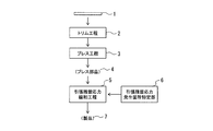
- the present embodiment includes a trim step 2 as a pre-step of press forming, a press step 3, and a tensile residual stress relaxation step 5. Further, the present embodiment has a portion 6 for specifying a location where tensile residual stress is generated.
- the metal plate 1 is cut into, for example, a contour shape corresponding to the part shape of the pressed part 4.
- the metal plate 1 after the trim step 2 is press-molded using a press die having an upper die and a lower die to manufacture a press part 4 having a target part shape.
- the press molding is, for example, foam molding or draw molding.
- the press process 3 constitutes the first press forming process.
- the pressed part 4 is manufactured by multi-step press forming.
- the press forming in which it is estimated that a tensile residual stress is generated in a part of the sheared end face of the metal plate 1 in the direction along the shear edge after the mold release is the last. It does not have to be press molded.
- the residual tensile residual stress after the final press molding of multi-step press molding is the tensile residual stress relaxation step 5. It becomes the tensile residual stress relaxed by.
- the presumed press molding is the first press molding step.
- the portion 6 for specifying the location where the tensile residual stress is generated performs a process of identifying the location where the tensile residual stress is generated on the sheared end face of the metal plate after the completion of the press step 3.
- the first method for identifying the location where tensile residual stress is generated is a method in which the sheared metal plate 1 is actually press-formed and the residual stress after demolding of the press-formed product is directly measured.
- the second method of identifying the location where tensile residual stress occurs is a method of estimating the location where tensile residual stress occurs after mold release by molding analysis.
- the first method is carried out by a destructive test method or a non-destructive test method.
- Destruction test methods include cutting and drilling methods.
- the measured value is not sufficiently accurate in the measurement of the bending deformation imparted portion of the press-formed product.
- the drilling method makes it difficult to measure the residual stress of the shear edge.
- a non-destructive test method there is a method of measuring residual stress by X-ray. This method can measure the residual stress of the shear edge and has sufficient accuracy, but it is not practical because the measurement takes a very long time.
- the location where the tensile residual stress is generated is specified by the following second method, that is, the method of estimating the location by molding analysis.
- the second method a method of performing molding analysis represented by the finite element method and estimating the residual stress after mold release is preferable.
- the accuracy of the molding analysis is not improved, the error of the calculation result of the residual stress becomes large. It is the model that constitutes the material behavior in the molding analysis that greatly influences this. In particular, it is known that the accuracy is improved by applying the mobile curing model to the shape after mold release, and it is preferable to carry out the molding analysis using the mobile curing model from the viewpoint of analysis accuracy.
- the kinematic curing model include a linear kinematic curing law and a Yoshida-Uemori model.
- the shear edge is a uniaxial tensile deformation or bending deformation or a composite deformation of uniaxial tensile deformation and bending deformation, and the principal stress direction thereof is along the shear edge.
- the tensile residual stress exceeds a predetermined stress value.
- the method of setting the place where the tensile residual stress exceeds the predetermined stress value is 10 mm or more along the shear edge, and the element where the tensile residual stress exceeds the predetermined stress value is the shear edge.
- the predetermined stress value is preferably determined according to the tensile strength, material, plate thickness, and the like of the metal plate 1.
- the default stress value can be set, for example, by multiplying the tensile strength of the metal plate 1 by a coefficient to obtain a threshold, or by multiplying the yield stress of the metal plate 1 by the equivalent plastic strain and the coefficient. It doesn't matter how you do it.
- the default stress value is, for example, 200 MPa.
- the predetermined stress value is set to 100 MPa, for example.
- portion 6 for specifying the location where the tensile residual stress is generated may simply specify the sheared end face of the portion to be shrunk and flanged by press forming as a location where the tensile residual stress is estimated to be generated.
- ⁇ Tensile residual stress relaxation step 5> In the tensile residual stress relaxation step 5, the location of the sheared end face where it is estimated that the tensile residual stress specified by the tensile residual stress generation location specifying portion 6 is generated in the press part 4 press-formed into the target component shape in the press step 3.
- the region ARA containing S is overhanged and molded in the plate thickness direction (see FIG. 2). In the direction along the shear edge, the region ARA to be overhanged may be set beyond the region including the shear end face portion S where the tensile residual stress is estimated to be generated.
- the region ARA to be stretched is set so that the tensile deformation in the direction along the shear edge caused by the stretch molding extends over the entire area of the shear end face where the tensile residual stress is estimated to occur.
- the overhang is surely along the shear edge generated by the overhang molding.
- the tensile deformation in the direction extends over the entire area S of the shear end face where tensile residual stress is estimated to occur.
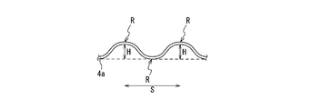
- the overhang shape by overhang molding for example, as shown in FIG. 2, the shape seen from the side facing the shear end face is an arc shape (a bead shape having an arc-shaped cross section, etc.).
- the overhang shape may be composed of, for example, a bead shape or a corrugated shape having a continuous arc shape extending in a direction along a shear edge as shown in FIG.
- the overhang shape is preferably formed into an overhang shape having an overhang height H of 10 mm or more and a radius of curvature R of 5 mm or more in the direction along the shear edge at the overhang apex.
- the overhang height H is the height at the top of the overhang shape.
- the profile of the overhanging shape has a radius of curvature R of 5 mm or more at any position along the edge direction.
- the upper limit of the radius of curvature R is not limited as long as it is 5 mm or more.
- An infinite radius of curvature R indicates a flat cross section.
- the radius of curvature R may be the radius of curvature on either the convex side surface or the concave side surface in the overhang shape, but in the present embodiment, it is the curvature radius on the convex side surface.
- the overhanging apex is set so as to be located in the shear end face portion S in the direction along the shear edge (see FIG. 2).
- the overhanging apex is preferably provided at the central portion of the sheared end face in the direction along the shear edge.
- the central portion is, for example, the central compartment position when the shear end face portion S is divided into three equal parts.
- the upper limit of the overhang height H is 200 mm. If it exceeds this, the strain generated at the shear edge during press forming becomes large, and an stretch flange may be generated. In addition, wrinkles, which are one of molding defects, may occur inside the press-molded product. More preferably, the overhang height H is preferably 100 mm or less.
- the difference in line length before and after overhang molding satisfies the following formula (A).
- the upper limit of the line length difference (X1-X2) before and after the overhang molding is naturally defined from the overhang height H and the radius of curvature R.
- the above-mentioned overhang shape is a shape at the end face of the metal plate 1, and the overhang shape at other parts is not particularly limited.
- the overhang height H of the overhang shape is continuously reduced from the end face to the inside, that is, as the distance from the end face is along the surface of the metal plate 1. It should be set so as to be. That is, only the vicinity of the end face needs to be overhanged.
- the vicinity of the end face is, for example, a range within 10 mm, preferably within 5 mm from the end face. By limiting to this range, the influence on the component shape of the pressed component 4 manufactured in the pressing process 3 can be suppressed to a small value.
- press forming may be performed to reduce the overhang height H of the overhang shape of the end portion formed in the tensile residual stress relaxation step 5.
- the shape of the part having the overhang shape formed in the tensile residual stress relaxation step 5 is designed as the shape of the product 7, and in the press part 4 produced in the press step 3, the overhang shape is formed into a flat shape. You may design.
- the extension molding by the tensile residual stress relaxation step 5 may be performed on the entire shear end face without limiting to the shear end face where the tensile residual stress is estimated to be generated.
- the line length of the shear edge of the portion where the tensile residual stress is generated is increased by the overhang shape by the overhang molding, and the tensile deformation excluding compression is imparted.
- the tensile stress during molding after the release of the overhang molding is released, and the tensile residual stress can be reduced.
- the overhanging shape preferably satisfies the following conditions (1) to (3).
- (1) Plastic deformation can be applied to the shear edge where tensile residual stress is generated by overhang deformation.
- Overhang deformation can be applied to a region wider than the region where tensile residual stress is generated on the shear edge. Applying tensile deformation (3) After applying tensile stress to the sheared edge by overhang deformation, the tensile stress is sufficiently released at the time of demolding. If the condition of (1) is not satisfied, the original after demolding. Since it returns to its shape, the tensile stress remains as it is.
- condition (2) If the condition (2) is not satisfied, a region having a large tensile residual stress may remain on the shear edge, and the occurrence of delayed fracture may not be sufficiently suppressed. If the condition (3) is not satisfied, there is a possibility that a new delayed fracture occurrence concern portion may be created by overhang molding such as bead molding.
- the overhanging shape that fully exerts the effects of the present embodiment.
- the overhang height H is 10 mm or more and the radius of curvature R of the apex portion of the overhang shape is 5 mm or more, the above conditions (1) to (3) are satisfied and shearing is performed. It was found that it is possible to apply plastic deformation to the portion where tensile residual stress is generated on the edge by overhang deformation, and it is possible to reduce the tensile residual stress of the sheared end face after press molding.
- the overhang height H is smaller than 10 mm, sufficient plastic deformation cannot be imparted to the portion where the tensile residual stress is generated at the shear edge, and the effect of suppressing delayed fracture may not be expected. More preferably, the overhang height H is 20 mm or more and the radius of curvature R of the apex of the overhang shape is 10 mm or more.
- the overhang shape is required to apply tensile deformation by overhang deformation to a region wider than the region where tensile residual stress is generated at the shear edge.
- the width of the overhang shape in the direction along the shear edge of the metal plate 1 was set to L1, and the molding analysis of the metal plate 1 was carried out. Based on the molding analysis result after the mold release, the tensile residual stress was applied to the sheared end face.
- the condition (2) can be surely satisfied if the overhanging shape is such that “L1> L0”.
- the strain to be applied is distributed in the part where the overhang shape is applied, but if the formula "X1> 1.03 ⁇ X0" can be satisfied, plastic deformation occurs in the entire region where tensile residual stress is generated at the shear edge. Can be applied, and the tensile stress of the entire region where the tensile residual stress is generated at the shear edge can be reduced. More preferably, the overhang shape such that "X1> 1.10 ⁇ X0" is preferable.
- the present embodiment it is possible to reduce the tensile residual stress of the sheared end face of the metal plate after press forming. As a result, according to the present embodiment, it is possible to improve the delayed fracture resistance when applying the high-strength steel sheet to various parts such as automobile panel parts, structural / frame parts, and the like.
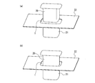
- a square tube drawing was performed on a metal plate 1 sheared to 400 mm ⁇ 400 mm with a die as shown in FIG. That is, with the outer circumference of the metal plate 1 restrained by the blank holder 22 and the die 21, the punch 20 is moved toward the die 21 and press-formed.
- the punch R was 25 mm and the molding depth was 25 mm.
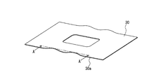
- a wavy bead shape as shown in FIGS. 5 to 7 is formed on the flange portion of the metal plate 1 obtained by square tube drawing.
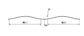
- a test product was manufactured by performing foam molding with a press die composed of an upper die 30 and a lower die 31.
- the bead shapes of the upper die 30 and the lower die 31 are the same, and as shown in FIG. 7, the bead shape having a height h and a bending radius R0 is transferred to the end of the metal plate by press forming. That is, overhang molding was performed to impart a continuous corrugated overhang shape along the edge to the sheared end face of the metal plate.
- the bead shape is set so that the height is continuously reduced from the end to the inside. At this time, as shown in Table 2, a plurality of test products were manufactured by changing the overhang height of the formed overhang shape and the radius of curvature of the overhang top.
- the chemical solution used for immersion in the immersion test was composed of a 0.1% concentration NH 4 SCN solution and a McILVAINE buffer solution to prepare a chemical solution having a pH of 5.6.
- the immersion time was 24 hours.
- molding analysis was performed by square tube drawing and overhang molding, and the stress generated at the shear edge was calculated.
- the molding analysis was a 1/4 model in consideration of symmetry.
- a Yoshida-Uemori model was used as the material model, and the residual stress after mold release was evaluated in the molding analysis.
- Tables 2 to 4 show the results of the immersion test and the residual stress measurement of the test product using the overhanging mold.
- the width L1 of the overhang shape is the position shown in FIG.
- the line length X1 after molding is the position shown in FIG.
Abstract
Description
なお、プレス成形で縮みフランジ変形を伴うプレス加工では、離型後のスプリングバックによって、せん断端面に引張残留応力が付与されることが知られている。 At present, automobiles are required to improve fuel efficiency and collision safety by reducing the weight. For this reason, high-strength steel plates are used in automobiles for the purpose of achieving both weight reduction of the vehicle body and protection of passengers in the event of a collision. In particular, in recent years, there has been a tendency to apply ultra-high strength steel plates having a tensile strength of 980 MPa or more to the vehicle body. One of the problems when applying ultra-high-strength steel sheets to vehicle bodies is delayed fracture that occurs over time due to use. In particular, in press working of a steel sheet having a tensile strength of 1470 MPa or more, delayed fracture generated from an end face (hereinafter, also referred to as a shear end face) after shearing has become an important issue.
It is known that in press working with shrinkage flange deformation in press forming, tensile residual stress is applied to the sheared end face by springback after mold release.
従来、せん断端面の引張残留応力を低減するために、例えばせん断加工時の鋼板温度を上昇させる方法(非特許文献1、2)や、穴抜き加工時に段付きパンチを用いる方法(非特許文献3)、更に、シェービングによる方法(非特許文献4、特許文献1)など、せん断加工を工夫する方法が広く開発されている。
なお、特許文献2には、スプリングバックを低減し部品の寸法精度を高めることを目的として、縮みフランジ成形部位に複数の余肉ビードを形成して引張応力を与えると共に、伸びフランジ成形部位にエンボスを形成し該エンボスを潰して圧縮応力を与えることが記載されている。 In order to suppress delayed fracture of the sheared end face, it is necessary to reduce the tensile residual stress of the sheared end face.
Conventionally, in order to reduce the tensile residual stress of the sheared end face, for example, a method of raising the temperature of the steel plate during shearing (Non-Patent Documents 1 and 2) and a method of using a stepped punch during drilling (Non-Patent Document 3). ), Further, methods for devising shearing processing such as a shaving method (
In
また、特許文献2に記載の方法は、スプリングバックを低減するための技術であり、遅れ破壊対策技術ではない。更に、特許文献2に記載の余肉ビードは、縮みフランジ部の圧縮応力を低減させるために導入しており、遅れ破壊の原因となるせん断端面の引張残留応力の低減を目的としたものではない。 However, the methods described in Non-Patent Documents and Patent Document 1 are techniques for preventing delayed fracture during shearing, and are not techniques for reducing residual stress on the sheared end face generated in the process of press forming a metal plate after shearing. ..
Further, the method described in
そして、課題を解決するために、本発明の一態様によれば、せん断端面を有する金属板をプレス成形してプレス部品を製造するプレス部品の製造方法であって、離型後に上記金属板のせん断端面の一部にせん断縁に沿った方向に引張残留応力が発生すると推定される第1のプレス成形工程を含み、上記第1のプレス成形工程の後工程として、少なくとも上記引張残留応力が発生すると推定されるせん断端面の箇所を含む領域を、板厚方向に張出し成形する引張残留応力緩和工程を有することを要旨とする。 In order to solve the above-mentioned problems, the inventor applies an overhang deformation to the end face of the contracted flange deformed portion by press molding so as to form a bead, thereby giving a tensile deformation to the shear end face, and then a spring after mold release. It was discovered that the tensile residual stress of the sheared end face generated by back deformation can be reduced.
Then, in order to solve the problem, according to one aspect of the present invention, it is a method of manufacturing a pressed part for manufacturing a pressed part by press-molding a metal plate having a sheared end face, and the above-mentioned metal plate is manufactured after mold release. A part of the sheared end face includes a first press forming step in which it is estimated that tensile residual stress is generated in the direction along the shear edge, and at least the tensile residual stress is generated as a subsequent step of the first press forming step. The gist is to have a tensile residual stress relaxation step in which the region including the presumed sheared end face is overhanged and formed in the plate thickness direction.
<金属板>
まず、プレス成形される金属板について説明する。
本実施形態で例示する金属板は、プレス成形後に有するせん断端面の引張り残留応力によって、プレス成形後に経時的に端部で遅れ破壊が起こる可能性のある高強度鋼板からなる。本発明は、金属板の引張強度が590MPa以上の高強度鋼板に好適に適用可能であるが、遅れ破壊が特に懸念される980MPa以上を有する高強度鋼板に効果的であり、1180MPa以上を有する高強度鋼板により効果的な技術である。
ここで、せん断端面の引張り残留応力は、端部のせん断の際にも入力される。
本実施形態では、図1に示すように、プレス成形の前工程としてのトリム工程2と、プレス工程3と、引張残留応力緩和工程5とを有する。また、本実施形態は、引張残留応力発生箇所特定部6を有する。 Next, an embodiment of the present invention will be described with reference to the drawings.
<Metal plate>
First, the press-formed metal plate will be described.
The metal plate illustrated in the present embodiment is made of a high-strength steel plate which may cause delayed fracture at the end portion over time after press forming due to the tensile residual stress of the sheared end face held after press forming. The present invention is suitably applicable to high-strength steel sheets having a tensile strength of 590 MPa or more, but is effective for high-strength steel sheets having 980 MPa or more, which is particularly concerned about delayed fracture, and has a high tensile strength of 1180 MPa or more. This is a technology that is more effective with strong steel sheets.
Here, the tensile residual stress of the sheared end face is also input when the end is sheared.
As shown in FIG. 1, the present embodiment includes a
トリム工程2では、金属板1を、例えば、プレス部品4の部品形状に応じた輪郭形状に切断する。 <
In the
プレス工程3では、トリム工程2後の金属板1を、上型と下型とを有するプレス金型を用いてプレス成形を行い、目的部品形状からなるプレス部品4を製造する。なお、プレス成形は、例えば、フォーム成形やドロー成形である。プレス工程3は、第1のプレス成形工程を構成する。 <Press process 3>
In the press step 3, the metal plate 1 after the
引張残留応力発生箇所特定部6は、プレス工程3の完了後の金属板におけるせん断端面に発生する、引張残留応力の発生箇所を特定する処理を行う。
引張残留応力の発生箇所を特定する第1の方法は、せん断加工した金属板1を実際にプレス成形し、プレス成形品の離形後の残留応力を直接測定する方法である。引張残留応力の発生箇所を特定する第2の方法は、成形解析により離形後の引張残留応力の発生箇所を推定する方法である。 <Specification of location where tensile residual stress occurs 6>
The portion 6 for specifying the location where the tensile residual stress is generated performs a process of identifying the location where the tensile residual stress is generated on the sheared end face of the metal plate after the completion of the press step 3.
The first method for identifying the location where tensile residual stress is generated is a method in which the sheared metal plate 1 is actually press-formed and the residual stress after demolding of the press-formed product is directly measured. The second method of identifying the location where tensile residual stress occurs is a method of estimating the location where tensile residual stress occurs after mold release by molding analysis.
このような観点から、本実施形態では、引張残留応力の発生箇所の特定を、次の第2の方法、つまり、成形解析により発生箇所を推定する方法で行う場合とする。
第2の方法としては、有限要素法に代表される成形解析を実施し、離型後の残留応力を推定する方法が好ましい。 The first method is carried out by a destructive test method or a non-destructive test method. Destruction test methods include cutting and drilling methods. In the cutting method, the measured value is not sufficiently accurate in the measurement of the bending deformation imparted portion of the press-formed product. The drilling method makes it difficult to measure the residual stress of the shear edge. As a non-destructive test method, there is a method of measuring residual stress by X-ray. This method can measure the residual stress of the shear edge and has sufficient accuracy, but it is not practical because the measurement takes a very long time.
From this point of view, in the present embodiment, the location where the tensile residual stress is generated is specified by the following second method, that is, the method of estimating the location by molding analysis.
As the second method, a method of performing molding analysis represented by the finite element method and estimating the residual stress after mold release is preferable.
また、引張残留応力発生箇所特定部6は、簡易的に、プレス成形で縮みフランジ成形する部分のせん断端面を、引張残留応力が発生すると推定される箇所として特定しても良い。 Of the shear end faces of the metal plate 1 released after press molding, as a method for determining a region including the shear end face where tensile residual stress is generated in the direction along the shear edge, for example, the tensile residual stress exceeds a predetermined stress value. The method of setting the place where the tensile residual stress exceeds the predetermined stress value is 10 mm or more along the shear edge, and the element where the tensile residual stress exceeds the predetermined stress value is the shear edge. There is a method in which the portions are connected in a direction perpendicular to the direction of 3 mm or more, but any method may be used. The predetermined stress value is preferably determined according to the tensile strength, material, plate thickness, and the like of the metal plate 1. The default stress value can be set, for example, by multiplying the tensile strength of the metal plate 1 by a coefficient to obtain a threshold, or by multiplying the yield stress of the metal plate 1 by the equivalent plastic strain and the coefficient. It doesn't matter how you do it. The default stress value is, for example, 200 MPa. When the metal plate 1 is a high-strength steel plate having 1180 MPa or more, for example, the predetermined stress value is set to 100 MPa, for example.
Further, the portion 6 for specifying the location where the tensile residual stress is generated may simply specify the sheared end face of the portion to be shrunk and flanged by press forming as a location where the tensile residual stress is estimated to be generated.
引張残留応力緩和工程5は、プレス工程3で目的部品形状にプレス成形されたプレス部品4に対し、引張残留応力発生箇所特定部6が特定した引張残留応力が発生すると推定されるせん断端面の箇所Sを含む領域ARAを、板厚方向に張出し成形する(図2参照)。せん断縁に沿った方向において、引張残留応力が発生すると推定されるせん断端面の箇所Sを含む領域を越えて、張出し成形する領域ARAを設定しても良い。
張出し成形する領域ARAは、張出し成形に伴って生じるせん断縁に沿った方向の引っ張り変形が、引張残留応力が発生すると推定されるせん断端面の箇所の全域に及ぶように設定する。 <Tensile residual
In the tensile residual
The region ARA to be stretched is set so that the tensile deformation in the direction along the shear edge caused by the stretch molding extends over the entire area of the shear end face where the tensile residual stress is estimated to occur.
張出し成形による張出し形状は、例えば、図2に示すように、せん断端面に対向する側からみた形状が、円弧形状(断面円弧状のビード形状など)となっている。張出し形状は、例えば、図3のような、ビード形状やせん断縁に沿った方向に延在する、円弧形状が連続した波型形状から構成されていても良い。 When the shear edge is overhanged in the direction along the shear edge for a length exceeding the shear end face portion S where the tensile residual stress is estimated to be generated, the overhang is surely along the shear edge generated by the overhang molding. The tensile deformation in the direction extends over the entire area S of the shear end face where tensile residual stress is estimated to occur.
As for the overhang shape by overhang molding, for example, as shown in FIG. 2, the shape seen from the side facing the shear end face is an arc shape (a bead shape having an arc-shaped cross section, etc.). The overhang shape may be composed of, for example, a bead shape or a corrugated shape having a continuous arc shape extending in a direction along a shear edge as shown in FIG.
曲率半径Rは、5mm以上であれば上限に限定はない。曲率半径Rが無限大は断面が平坦であることを示す。
また、曲率半径Rは、張出し形状における、凸側の面又は凹側の面のどちらの面での曲率半径でも良いが、本実施形態では凸側の面での曲率半径とする。 Further, the overhang shape is preferably formed into an overhang shape having an overhang height H of 10 mm or more and a radius of curvature R of 5 mm or more in the direction along the shear edge at the overhang apex. The overhang height H is the height at the top of the overhang shape. It is preferable that the profile of the overhanging shape has a radius of curvature R of 5 mm or more at any position along the edge direction.
The upper limit of the radius of curvature R is not limited as long as it is 5 mm or more. An infinite radius of curvature R indicates a flat cross section.
Further, the radius of curvature R may be the radius of curvature on either the convex side surface or the concave side surface in the overhang shape, but in the present embodiment, it is the curvature radius on the convex side surface.
張出し高さHの上限値は200mmである。これを超えるとプレス成形時にせん断縁に発生するひずみが大きくなり、伸びフランジが発生するおそれがある。また、プレス成形品内部に成形不良の一つであるしわが発生する可能性もある。より好ましくは、張出し高さHは100mm以下とするのが良い。 Further, the overhanging apex is set so as to be located in the shear end face portion S in the direction along the shear edge (see FIG. 2). When one overhanging apex is arranged in the sheared end face portion S, the overhanging apex is preferably provided at the central portion of the sheared end face in the direction along the shear edge. The central portion is, for example, the central compartment position when the shear end face portion S is divided into three equal parts.
The upper limit of the overhang height H is 200 mm. If it exceeds this, the strain generated at the shear edge during press forming becomes large, and an stretch flange may be generated. In addition, wrinkles, which are one of molding defects, may occur inside the press-molded product. More preferably, the overhang height H is preferably 100 mm or less.
X1 > 1.03・X0 ・・・(A)
なお、張出し成形前後の線長差(X1-X2)の上限値は、張出し高さHと曲率半径Rとから自ずと規定される。 Further, in the overhang molding, when the length of the part to be overhanged along the shear edge before overhanging is X0 and the length of the part to be overhanged along the shear edge after overhanging is X1. It is preferable that the difference in line length before and after overhang molding satisfies the following formula (A).
X1> 1.03 ・ X0 ・ ・ ・ (A)
The upper limit of the line length difference (X1-X2) before and after the overhang molding is naturally defined from the overhang height H and the radius of curvature R.
ここで、引張残留応力緩和工程5の後工程として、引張残留応力緩和工程5で形成した、端部の張出し形状の張出し高さHを小さくするプレス成形を実施しても良い。
また、引張残留応力緩和工程5で成形した張出し形状を有する部品形状を製品7の形状として設計し、プレス工程3で作製するプレス部品4では、その張出し形状を平坦にした形状に成形するように設計しても良い。
また、引張残留応力が発生すると推定されるせん断端面に限定せず、せん断端面全域を対象として、引張残留応力緩和工程5による張出し成形を施しても良い。 <Other configurations>
Here, as a subsequent step of the tensile residual
Further, the shape of the part having the overhang shape formed in the tensile residual
Further, the extension molding by the tensile residual
(引張残留応力発生の様態)
ここで、プレス工程3で、角筒絞り成形を行い、プレス成形品のせん断端面に引張変形が発生する場合を例に説明する。
プレス工程3で、正方形の金属板1の中央部に角筒絞りをすると、絞りに伴う材料流入が生じつつ、金属板1の中央部は角筒状に変形する。このとき、角筒の外周のフランジ部におけるせん断縁の一部分は、せん断縁に沿った方向に縮みを伴う変形、つまり、縮みフランジ変形する。角筒絞りに伴い、せん断縁の部分には、縮みフランジ変形による圧縮応力が発生しており、一方で、縮みフランジ変形部近傍に、せん断縁の流入差や摩擦抵抗に伴う引張応力も発生している。このため、せん断縁に沿って不均一な応力分布が発生している。このように、金型に拘束されたプレス部品4には、プレス成形によって不均一な応力分布が生じている。この状態から、離型して不均一な応力分布を開放すると、プレス部品4には内部応力が残存し、これが残留応力となる。この残留応力のうち引張応力が、プレス成形後のプレス部品4での遅れ破壊発生の一要因となる。 <Action and others>
(Mode of tensile residual stress generation)
Here, a case where square tube drawing molding is performed in the press step 3 and tensile deformation occurs on the sheared end face of the press-molded product will be described as an example.
When a square tube drawing is performed on the central portion of the square metal plate 1 in the pressing step 3, the central portion of the metal plate 1 is deformed into a square tube shape while the material inflow accompanying the drawing occurs. At this time, a part of the shear edge in the flange portion on the outer periphery of the square cylinder is deformed with shrinkage in the direction along the shear edge, that is, the shrinkage flange is deformed. Along with the square tube drawing, compressive stress is generated at the shear edge due to the deformation of the shrink flange, while tensile stress due to the inflow difference of the shear edge and frictional resistance is also generated near the deformed shrink flange. ing. Therefore, a non-uniform stress distribution is generated along the shear edge. As described above, the pressed
発明者らは鋭意検討の結果、プレス成形後に上記のような引張残留応力が残存する部品の端部に張出し変形を加えることで、引張残留応力を低減できることを見出した。これについて、以下の通り説明する。
プレス成形品のせん断縁に引張残留応力が発生するのは、前述した通り成形中の引張と圧縮の不均一な応力分布が発生することが主要因である。本実施形態では、これを解消するために、引張残留応力緩和工程5にて、引張残留応力が発生する部分に均一な変形を加える。具体的には、引張残留応力緩和工程5にて、張出し成形による張出し形状によって引張残留応力発生部分のせん断縁の線長を増やし、圧縮を含まない引張変形を付与する。これによって、張出し成形の離型後に成形中の引張応力が解放されて、引張残留応力を低減することができる。 (Method for reducing tensile residual stress)
As a result of diligent studies, the inventors have found that the tensile residual stress can be reduced by applying overhang deformation to the end portion of the part in which the tensile residual stress remains after press forming. This will be described as follows.
As described above, the reason why the tensile residual stress is generated at the shear edge of the press-formed product is that the non-uniform stress distribution of tension and compression during molding is generated. In the present embodiment, in order to eliminate this, uniform deformation is applied to the portion where the tensile residual stress is generated in the tensile residual
(1) せん断縁に、引張残留応力が発生している部分に対し、張出し変形により塑性変形を付与できること
(2) せん断縁に、引張残留応力が発生している領域より広い領域に張出し変形により引張変形を付与すること
(3) せん断縁に、張出し変形によって引張応力を付与した後、離形時にその引張応力が十分解放されること
(1)の条件が満たされない場合、離型後に元の形状に戻ってしまうため、引張応力はそのまま残存してしまう。
(2)の条件が満たされない場合、せん断縁に引張残留応力が大きい領域が残存してしまうおそれがあり、遅れ破壊発生を十分に抑制できないおそれがある。
(3)の条件が満たされない場合、ビード成形などの張出し成形によって新たに遅れ破壊発生懸念箇所を作るおそれがある。 The overhanging shape preferably satisfies the following conditions (1) to (3).
(1) Plastic deformation can be applied to the shear edge where tensile residual stress is generated by overhang deformation. (2) Overhang deformation can be applied to a region wider than the region where tensile residual stress is generated on the shear edge. Applying tensile deformation (3) After applying tensile stress to the sheared edge by overhang deformation, the tensile stress is sufficiently released at the time of demolding. If the condition of (1) is not satisfied, the original after demolding. Since it returns to its shape, the tensile stress remains as it is.
If the condition (2) is not satisfied, a region having a large tensile residual stress may remain on the shear edge, and the occurrence of delayed fracture may not be sufficiently suppressed.
If the condition (3) is not satisfied, there is a possibility that a new delayed fracture occurrence concern portion may be created by overhang molding such as bead molding.
発明者らが検討を重ねた結果、張出し高さHが10mm以上かつ張出し形状の頂点部の曲率半径Rが5mm以上であれば、上記の(1)~(3)の条件を満足し、せん断縁に引張残留応力が発生している部分に張出し変形により塑性変形を付与することが可能であり、プレス成形後のせん断端面の引張残留応力を低減することができることが分かった。
張出し形状の頂点部の曲率半径Rが5mmより小さいと、張出し成形により頂点部に局所的に大きな変形を伴った形状がついてしまい、離形後にも引張応力が残存し、これが遅れ破壊の発生要因となってしまうおそれがある。
また、張出し高さHが10mmより小さいと、せん断縁に引張残留応力が発生している部分に十分に塑性変形が付与できずに、遅れ破壊抑制効果が期待できないおそれがある。より好ましくは、張出し高さHが20mm以上かつ張出し形状の頂点部の曲率半径Rが10mm以上とするのが良い。 For the above reasons, there are restrictions on the overhanging shape that fully exerts the effects of the present embodiment.
As a result of repeated studies by the inventors, if the overhang height H is 10 mm or more and the radius of curvature R of the apex portion of the overhang shape is 5 mm or more, the above conditions (1) to (3) are satisfied and shearing is performed. It was found that it is possible to apply plastic deformation to the portion where tensile residual stress is generated on the edge by overhang deformation, and it is possible to reduce the tensile residual stress of the sheared end face after press molding.
If the radius of curvature R of the apex of the overhang shape is smaller than 5 mm, the apex will be locally deformed by the overhang molding, and tensile stress will remain even after the shape is removed, which is a cause of delayed fracture. There is a risk of becoming.
Further, if the overhang height H is smaller than 10 mm, sufficient plastic deformation cannot be imparted to the portion where the tensile residual stress is generated at the shear edge, and the effect of suppressing delayed fracture may not be expected. More preferably, the overhang height H is 20 mm or more and the radius of curvature R of the apex of the overhang shape is 10 mm or more.
なお、L1の上限は、張出し高さHや曲率半径Rから自ずと規定される。 As described in the condition (2) above, the overhang shape is required to apply tensile deformation by overhang deformation to a region wider than the region where tensile residual stress is generated at the shear edge. As a result of diligent examination, the width of the overhang shape in the direction along the shear edge of the metal plate 1 was set to L1, and the molding analysis of the metal plate 1 was carried out. Based on the molding analysis result after the mold release, the tensile residual stress was applied to the sheared end face. When the length of the region where the above is generated is L0, the condition (2) can be surely satisfied if the overhanging shape is such that “L1> L0”. This is because a region wider than the region where the tensile residual stress remains along the shear edge is overhanged and molded to impart tensile deformation. More preferably, it is an overhanging shape having a size of "L1> 1.1 · L0".
The upper limit of L1 is naturally defined from the overhang height H and the radius of curvature R.
ここでは、表1に示す機械的特性を有する1470MPa級冷延鋼板を対象に説明する。 Next, an example based on the present invention will be described.
Here, a 1470 MPa class cold-rolled steel sheet having the mechanical properties shown in Table 1 will be described.

パンチRは25mm、成形深さは25mmとした。 As a pressing step (hereinafter, also referred to as the first step), a square tube drawing was performed on a metal plate 1 sheared to 400 mm × 400 mm with a die as shown in FIG. That is, with the outer circumference of the metal plate 1 restrained by the
The punch R was 25 mm and the molding depth was 25 mm.
なお、ビード形状は、端部から内側に向けて高さが連続的に小さくなるように設定されている。
このとき、表2に示すように、成形された張出し形状の張出し高さ及び張出し頂部の曲率半径を変更して、複数の試験品を製造した。 Next, as a tensile residual stress relaxation step (hereinafter, also referred to as the second step), a wavy bead shape as shown in FIGS. 5 to 7 is formed on the flange portion of the metal plate 1 obtained by square tube drawing. A test product was manufactured by performing foam molding with a press die composed of an
The bead shape is set so that the height is continuously reduced from the end to the inside.
At this time, as shown in Table 2, a plurality of test products were manufactured by changing the overhang height of the formed overhang shape and the radius of curvature of the overhang top.
浸漬試験の浸漬に使用した薬液は、0.1%濃度のNH4SCN溶液とMcILVAINE緩衝溶液とを合わせて構成し、pHが5.6の薬液とした。また、浸漬時間は24時間とした。
そして、浸漬後のせん断端面から発生する割れの有無を確認し、模擬的に遅れ破壊の割れ判定とした。
また、角筒絞り及び張出し成形による成形解析を実施し、せん断縁に発生した応力を算出した。成形解析は対称性を考慮して1/4モデルとした。材料モデルとしてはYoshida-Uemoriモデルを使用し、成形解析上で離型後の残留応力を評価した。
張出し形状を有した金型による試験品の浸漬試験及び残留応力測定の結果を、表2~表4に示す。ここで、張出形状の幅L1は、図8に示す位置である。成形後の線長X1は図9に示す位置である。 Next, an immersion test was carried out for each of the manufactured test products in order to simulate delayed fracture.
The chemical solution used for immersion in the immersion test was composed of a 0.1% concentration NH 4 SCN solution and a McILVAINE buffer solution to prepare a chemical solution having a pH of 5.6. The immersion time was 24 hours.
Then, the presence or absence of cracks generated from the sheared end face after immersion was confirmed, and the crack was determined to be delayed fracture in a simulated manner.
In addition, molding analysis was performed by square tube drawing and overhang molding, and the stress generated at the shear edge was calculated. The molding analysis was a 1/4 model in consideration of symmetry. A Yoshida-Uemori model was used as the material model, and the residual stress after mold release was evaluated in the molding analysis.
Tables 2 to 4 show the results of the immersion test and the residual stress measurement of the test product using the overhanging mold. Here, the width L1 of the overhang shape is the position shown in FIG. The line length X1 after molding is the position shown in FIG.


また、せん断縁の残留応力低減効果も確認できた。頂点部の曲率半径については、張出し高さHが40mmにおいて、頂点部の曲率半径が5mm~30mmでは、浸漬試験による割れが回避できた。一方で頂点部の曲率半径が3mmでは割れが発生した。
以上から、張出し形状の高さが10mm以上かつ張出し形状の頂点部の半径が5mm以上であることが適切であるといえる。 As can be seen from Table 2, when the overhang height of the overhang shape was 5 mm, cracks were generated by the immersion test, and when the overhang height was 10 mm to 40 mm, cracks due to the immersion test could be avoided.
In addition, the effect of reducing residual stress at the shear edge was also confirmed. Regarding the radius of curvature of the apex, when the overhang height H was 40 mm and the radius of curvature of the apex was 5 mm to 30 mm, cracking due to the immersion test could be avoided. On the other hand, when the radius of curvature of the apex was 3 mm, cracks occurred.
From the above, it can be said that it is appropriate that the height of the overhang shape is 10 mm or more and the radius of the apex of the overhang shape is 5 mm or more.
また、表4から分かるように、張出し高さが10mm、頂点部の曲率半径が104mmにおいて、X1とX0の比(X1/X0)が1.05と1.15だと浸漬試験による割れが発生せず、比(X1/X0)が1.02と1.03で割れが発生した。以上から、張出し成形の成形前の長さX0と成形後の長さX1の線長差について、X1> 1.03・X0が適切であるといえる。 Further, as can be seen from Table 3, cracks occur due to the immersion test when the ratio of L1 to L0 (L1 / L0) is 1.1 or more and 1.4 or less when the overhang height is H20 mm and the radius of the apex is 55 mm. Instead, cracks occurred when the ratio (L1 / L0) was 1.0. From the above, it can be said that it is appropriate to set L1> L0.
Further, as can be seen from Table 4, when the overhang height is 10 mm and the radius of curvature of the apex is 104 mm and the ratio of X1 to X0 (X1 / X0) is 1.05 and 1.15, cracks occur due to the immersion test. Instead, cracks occurred at ratios (X1 / X0) of 1.02 and 1.03. From the above, it can be said that X1> 1.03 · X0 is appropriate for the line length difference between the length X0 before molding and the length X1 after molding in overhang molding.
2 トリム工程
3 プレス工程(第1のプレス成形工程)
4 プレス部品
5 引張残留応力緩和工程
6 引張残留応力発生箇所特定部
7 製品 1
4
Claims (6)
- せん断端面を有する金属板をプレス成形してプレス部品を製造するプレス部品の製造方法であって、
離型後に上記金属板のせん断端面の一部にせん断縁に沿った方向に引張残留応力が発生すると推定される第1のプレス成形工程を含み、
上記第1のプレス成形工程の後工程として、少なくとも上記引張残留応力が発生すると推定されるせん断端面の箇所を含む領域を、板厚方向に張出し成形する引張残留応力緩和工程を有することを特徴とするプレス部品の製造方法。 It is a manufacturing method of a pressed part that manufactures a pressed part by press-molding a metal plate having a sheared end face.
Includes a first press forming step in which it is estimated that tensile residual stress is generated in a part of the shear end face of the metal plate in the direction along the shear edge after mold release.
As a subsequent step of the first press forming step, it is characterized by having a tensile residual stress relaxation step of at least extending and molding a region including a shear end face where the tensile residual stress is estimated to be generated in the plate thickness direction. How to manufacture stamped parts. - 上記引張残留応力緩和工程での張出し成形で形成される張出し形状を、せん断端面から離れるほど、張出し高さが小さくなるように設定することを特徴とする請求項1に記載したプレス部品の製造方法。 The method for manufacturing a pressed part according to claim 1, wherein the overhang shape formed by the overhang molding in the tensile residual stress relaxation step is set so that the overhang height becomes smaller as the distance from the sheared end face increases. ..
- 上記引張残留応力が発生すると推定される箇所を、上記金属板の成形解析を実施し、離型後の成形解析結果から特定することを特徴とする請求項1又は請求項2に記載したプレス部品の製造方法。 The pressed component according to claim 1 or 2, wherein the portion where the tensile residual stress is presumed to be generated is specified from the molding analysis result after the molding analysis of the metal plate is performed. Manufacturing method.
- 上記引張残留応力緩和工程での張出し成形で、せん断端面を、張出し高さが10mm以上で且つ張出し頂点部でのせん断縁に沿った方向の曲率半径が5mm以上の張出し形状に成形することを特徴とする請求項1~請求項3のいずれか1項に記載したプレス部品の製造方法。 In the overhang molding in the tensile residual stress relaxation step, the shear end face is formed into an overhang shape having an overhang height of 10 mm or more and a radius of curvature of 5 mm or more in the direction along the shear edge at the overhang apex. The method for manufacturing a pressed part according to any one of claims 1 to 3.
- 上記引張残留応力緩和工程での張出し成形で、上記せん断縁に沿った張出し成形される部分の張出し成形前の長さをX0とし、上記せん断縁に沿った張出し成形される部分の張出し成形後の長さをX1としたとき、下記(1)式を満足することを特徴とする請求項1~請求項4のいずれか1項に記載したプレス部品の製造方法。
X1 > 1.03・X0 ・・・(1) In the overhang molding in the tensile residual stress relaxation step, the length before the overhang molding of the portion to be overhanged along the shear edge is set to X0, and after the overhang molding of the portion to be overhanged along the shear edge. The method for manufacturing a pressed part according to any one of claims 1 to 4, wherein the method (1) is satisfied when the length is X1.
X1> 1.03 ・ X0 ・ ・ ・ (1) - 上記金属板の引張強度が980MPa以上であることを特徴とする請求項1~請求項5のいずれか1項に記載したプレス部品の製造方法。 The method for manufacturing a pressed part according to any one of claims 1 to 5, wherein the tensile strength of the metal plate is 980 MPa or more.
Priority Applications (6)
| Application Number | Priority Date | Filing Date | Title |
|---|---|---|---|
| EP20769722.8A EP3939712A4 (en) | 2019-03-14 | 2020-03-13 | Pressed component manufacturing method |
| KR1020217028923A KR102499446B1 (en) | 2019-03-14 | 2020-03-13 | Manufacturing method of press parts |
| MX2021011095A MX2021011095A (en) | 2019-03-14 | 2020-03-13 | Pressed component manufacturing method. |
| CN202080020866.2A CN113631290B (en) | 2019-03-14 | 2020-03-13 | Method for manufacturing press-molded part |
| US17/438,350 US20220234089A1 (en) | 2019-03-14 | 2020-03-13 | Pressed component manufacturing method |
| JP2020535000A JP6784346B1 (en) | 2019-03-14 | 2020-03-13 | Manufacturing method of pressed parts |
Applications Claiming Priority (2)
| Application Number | Priority Date | Filing Date | Title |
|---|---|---|---|
| JP2019047362 | 2019-03-14 | ||
| JP2019-047362 | 2019-03-14 |
Publications (1)
| Publication Number | Publication Date |
|---|---|
| WO2020184711A1 true WO2020184711A1 (en) | 2020-09-17 |
Family
ID=72426806
Family Applications (1)
| Application Number | Title | Priority Date | Filing Date |
|---|---|---|---|
| PCT/JP2020/011188 WO2020184711A1 (en) | 2019-03-14 | 2020-03-13 | Pressed component manufacturing method |
Country Status (7)
| Country | Link |
|---|---|
| US (1) | US20220234089A1 (en) |
| EP (1) | EP3939712A4 (en) |
| JP (1) | JP6784346B1 (en) |
| KR (1) | KR102499446B1 (en) |
| CN (1) | CN113631290B (en) |
| MX (1) | MX2021011095A (en) |
| WO (1) | WO2020184711A1 (en) |
Families Citing this family (1)
| Publication number | Priority date | Publication date | Assignee | Title |
|---|---|---|---|---|
| CN115446610B (en) * | 2022-07-21 | 2023-07-21 | 成都飞机工业(集团)有限责任公司 | Method for eliminating residual stress by cold pressing |
Citations (7)
| Publication number | Priority date | Publication date | Assignee | Title |
|---|---|---|---|---|
| JPH07171625A (en) * | 1993-12-20 | 1995-07-11 | Daiwa Kogyo Kk | Method for preventing deformation of press formed article |
| JPH07112574B2 (en) * | 1985-12-07 | 1995-12-06 | 東プレ株式会社 | Deformation prevention method for press-formed products |
| JP2003033828A (en) * | 2001-07-23 | 2003-02-04 | Toyota Motor Corp | Method and program for forming die model |
| JP2003311339A (en) * | 2002-04-26 | 2003-11-05 | Sumitomo Metal Ind Ltd | Press molded article, its manufacturing method and device |
| JP2006289480A (en) * | 2005-04-14 | 2006-10-26 | Aida Eng Ltd | Press forming method and metal mold used for the same |
| JP2017170484A (en) * | 2016-03-24 | 2017-09-28 | 新日鐵住金株式会社 | Structural member for vehicle, method for production thereof, and metallic mold |
| JP2019047362A (en) | 2017-09-04 | 2019-03-22 | 公立大学法人首都大学東京 | Search system |
Family Cites Families (8)
| Publication number | Priority date | Publication date | Assignee | Title |
|---|---|---|---|---|
| JPS60148628A (en) * | 1984-01-13 | 1985-08-05 | Toyota Motor Corp | Drawing press die of square cylinder vessel |
| JP2004174542A (en) | 2002-11-26 | 2004-06-24 | Fukae Kosakusho:Kk | Method for press-working metallic plate material |
| JP5380890B2 (en) | 2008-04-15 | 2014-01-08 | 新日鐵住金株式会社 | Press molding method and apparatus excellent in shape freezing property |
| JP4973631B2 (en) * | 2008-09-16 | 2012-07-11 | トヨタ自動車株式会社 | Molding method for press-molded products |
| CN104918725B (en) * | 2013-01-16 | 2016-09-14 | 新日铁住金株式会社 | Impact forming method |
| CN103341556A (en) * | 2013-06-26 | 2013-10-09 | 大连理工大学 | Mobile type draw bead device for reducing warping springback of lateral wall of stamped part and blank holding technique thereof |
| CN106794507B (en) * | 2015-02-27 | 2019-05-07 | 株式会社三五 | Method for press forming |
| JP7112574B1 (en) * | 2021-08-25 | 2022-08-03 | 株式会社ガバメイツ | BUSINESS MANAGEMENT SYSTEM, BUSINESS MANAGEMENT SUPPORT METHOD, AND PROGRAM |
-
2020
- 2020-03-13 KR KR1020217028923A patent/KR102499446B1/en active IP Right Grant
- 2020-03-13 US US17/438,350 patent/US20220234089A1/en active Pending
- 2020-03-13 MX MX2021011095A patent/MX2021011095A/en unknown
- 2020-03-13 CN CN202080020866.2A patent/CN113631290B/en active Active
- 2020-03-13 WO PCT/JP2020/011188 patent/WO2020184711A1/en active Application Filing
- 2020-03-13 JP JP2020535000A patent/JP6784346B1/en active Active
- 2020-03-13 EP EP20769722.8A patent/EP3939712A4/en active Pending
Patent Citations (7)
| Publication number | Priority date | Publication date | Assignee | Title |
|---|---|---|---|---|
| JPH07112574B2 (en) * | 1985-12-07 | 1995-12-06 | 東プレ株式会社 | Deformation prevention method for press-formed products |
| JPH07171625A (en) * | 1993-12-20 | 1995-07-11 | Daiwa Kogyo Kk | Method for preventing deformation of press formed article |
| JP2003033828A (en) * | 2001-07-23 | 2003-02-04 | Toyota Motor Corp | Method and program for forming die model |
| JP2003311339A (en) * | 2002-04-26 | 2003-11-05 | Sumitomo Metal Ind Ltd | Press molded article, its manufacturing method and device |
| JP2006289480A (en) * | 2005-04-14 | 2006-10-26 | Aida Eng Ltd | Press forming method and metal mold used for the same |
| JP2017170484A (en) * | 2016-03-24 | 2017-09-28 | 新日鐵住金株式会社 | Structural member for vehicle, method for production thereof, and metallic mold |
| JP2019047362A (en) | 2017-09-04 | 2019-03-22 | 公立大学法人首都大学東京 | Search system |
Non-Patent Citations (5)
| Title |
|---|
| "Sendankakou no saizensen", PROCEEDINGS OF THE 326TH SYMPOSIUM ON PLASTICITY, pages 21 - 28 |
| KENICHIRO MORI ET AL., JOURNAL OF JAPAN SOCIETY FOR TECHNOLOGY OF PLASTICITY, vol. 51-588, 2010, pages 55 - 59 |
| KENICHIRO MORI ET AL., JOURNAL OF JAPAN SOCIETY FOR TECHNOLOGY OF PLASTICITY, vol. 52-609, 2011, pages 1114 - 1118 |
| M. MURAKAWAM. SUZUKIT. SHINOMEF. KOMUROA. HARAIA. MATSUMOTON. KOGA: "Precision piercing and blanking of ultrahigh-strength steel sheets", PROCEDIA ENGINEERING, vol. 81, 2014, pages 1114 - 1120, XP029078417, DOI: 10.1016/j.proeng.2014.10.219 |
| See also references of EP3939712A4 |
Also Published As
| Publication number | Publication date |
|---|---|
| CN113631290A (en) | 2021-11-09 |
| KR20210124435A (en) | 2021-10-14 |
| CN113631290B (en) | 2023-04-28 |
| MX2021011095A (en) | 2021-10-22 |
| EP3939712A4 (en) | 2022-04-20 |
| EP3939712A1 (en) | 2022-01-19 |
| JP6784346B1 (en) | 2020-11-11 |
| JPWO2020184711A1 (en) | 2021-03-18 |
| US20220234089A1 (en) | 2022-07-28 |
| KR102499446B1 (en) | 2023-02-13 |
Similar Documents
| Publication | Publication Date | Title |
|---|---|---|
| CN111163875B (en) | Deformation limit evaluation method, fracture prediction method, and press die design method | |
| CN110997172B (en) | Method for evaluating deformation limit on sheared surface of metal plate, method for predicting crack, and method for designing press die | |
| JP6610607B2 (en) | Method for evaluating delayed fracture characteristics of high strength steel sheets | |
| KR102291185B1 (en) | Method for manufacturing press-formed products | |
| RU2692353C1 (en) | Production method of pressed products and production line for them | |
| US11534815B2 (en) | Press formed product, automobile structural member with the press formed product, and method for producing press formed product | |
| JP6614197B2 (en) | Method for evaluating delayed fracture characteristics of high strength steel sheets | |
| WO2020184711A1 (en) | Pressed component manufacturing method | |
| JP7188457B2 (en) | METHOD FOR SHEARING METAL PLATE AND METHOD FOR MANUFACTURING PRESS PARTS | |
| JP6977913B1 (en) | Manufacturing method of pressed parts and manufacturing method of blank material | |
| JP2019174124A (en) | Delayed fracture property evaluation method of high strength steel plate | |
| JP7318602B2 (en) | METHOD FOR MANUFACTURE OF TEST SPECIMEN AND METHOD FOR EVALUATION OF DELAYED FRACTURE CHARACTERISTICS OF HIGH-STRENGTH STEEL STEEL | |
| JP6319383B2 (en) | Manufacturing method of stretch flange molded parts | |
| WO2021171678A1 (en) | Press forming method and shape evaluation method for press formed article | |
| JP6319382B2 (en) | Manufacturing method of stretch flange molded parts | |
| KR20170081215A (en) | Press-forming method and method of manufacturing component employing same method, and press-forming device and formed component press-formed using same device | |
| JP7435895B2 (en) | Method for improving delayed fracture characteristics of metal plate, method for producing blank material, and method for producing press-formed product | |
| Sresomroeng et al. | Sidewall-curl prediction in U-bending process of advanced high strength steel | |
| Khalid Jawed et al. | Drawing of hexagonal shapes from cylindrical cups | |
| Saengkhiao et al. | Increasing the dimensional accuracy of U-bend product of high strength steel sheets by controlling the pressure pad | |
| JP2021186833A (en) | Rigidity evaluation method and shape determination method of press molding product, and press molding product | |
| Ohwue et al. | Experiment and static implicit analysis of springback in bend forming of a bumper model | |
| Bhattacharya et al. | Experimental Evaluation of Springback in Aluminium Alloys Using Optical Measurement and Numerical Analysis |
Legal Events
| Date | Code | Title | Description |
|---|---|---|---|
| ENP | Entry into the national phase |
Ref document number: 2020535000 Country of ref document: JP Kind code of ref document: A |
|
| 121 | Ep: the epo has been informed by wipo that ep was designated in this application |
Ref document number: 20769722 Country of ref document: EP Kind code of ref document: A1 |
|
| ENP | Entry into the national phase |
Ref document number: 20217028923 Country of ref document: KR Kind code of ref document: A |
|
| NENP | Non-entry into the national phase |
Ref country code: DE |
|
| WWE | Wipo information: entry into national phase |
Ref document number: 2020769722 Country of ref document: EP |
|
| ENP | Entry into the national phase |
Ref document number: 2020769722 Country of ref document: EP Effective date: 20211014 |