WO2020184582A1 - 金属製部品の破断開始部形成方法 - Google Patents
金属製部品の破断開始部形成方法 Download PDFInfo
- Publication number
- WO2020184582A1 WO2020184582A1 PCT/JP2020/010383 JP2020010383W WO2020184582A1 WO 2020184582 A1 WO2020184582 A1 WO 2020184582A1 JP 2020010383 W JP2020010383 W JP 2020010383W WO 2020184582 A1 WO2020184582 A1 WO 2020184582A1
- Authority
- WO
- WIPO (PCT)
- Prior art keywords
- forming
- laser
- laser beam
- metal part
- start portion
- Prior art date
- Legal status (The legal status is an assumption and is not a legal conclusion. Google has not performed a legal analysis and makes no representation as to the accuracy of the status listed.)
- Ceased
Links
Images



Classifications
-
- B—PERFORMING OPERATIONS; TRANSPORTING
- B23—MACHINE TOOLS; METAL-WORKING NOT OTHERWISE PROVIDED FOR
- B23K—SOLDERING OR UNSOLDERING; WELDING; CLADDING OR PLATING BY SOLDERING OR WELDING; CUTTING BY APPLYING HEAT LOCALLY, e.g. FLAME CUTTING; WORKING BY LASER BEAM
- B23K26/00—Working by laser beam, e.g. welding, cutting or boring
-
- B—PERFORMING OPERATIONS; TRANSPORTING
- B23—MACHINE TOOLS; METAL-WORKING NOT OTHERWISE PROVIDED FOR
- B23K—SOLDERING OR UNSOLDERING; WELDING; CLADDING OR PLATING BY SOLDERING OR WELDING; CUTTING BY APPLYING HEAT LOCALLY, e.g. FLAME CUTTING; WORKING BY LASER BEAM
- B23K26/00—Working by laser beam, e.g. welding, cutting or boring
- B23K26/36—Removing material
- B23K26/362—Laser etching
- B23K26/364—Laser etching for making a groove or trench, e.g. for scribing a break initiation groove
Definitions
- the present invention relates to a method for forming a fracture start portion of a metal part, for example, for forming a fracture start portion of a metal part such as an automobile connecting rod (hereinafter, simply referred to as a "connecting rod").
- the metal parts may be used as a pair of products by pulling and breaking and recombining the parts that have been split in half.
- An example of such a component is a connecting rod (hereinafter, simply referred to as a "connecting rod") known as an automobile component.
- Patent Document 1 describes a step of forming a groove portion by broaching at a portion corresponding to a fracture start portion of a metal part and a step of forming a plurality of recess portions at a predetermined interval from each other at a portion at the bottom of the groove portion.
- a method for forming a fracture start portion of a metal part having a metal part is disclosed.
- the focal point is defocused from the inner peripheral surface of the through hole by a certain amount to irradiate the inner peripheral surface of the through hole, and at the same time, an assist gas is supplied to the laser beam irradiation position to form a recessed portion.
- an assist gas is supplied to the laser beam irradiation position to form a recessed portion.
- the laser light is linearly moved from one side opening to the other side opening of the through hole inner peripheral surface at a predetermined speed.
- the present invention on the one hand, has been made in view of such circumstances, and an object of the present invention is to provide a method for forming a fracture start portion of a metal part with a simple configuration.
- the present invention adopts the following configuration in order to solve the above-mentioned problems.
- the method for forming a fracture start portion of a metal part is a fracture start portion of a metal part having a predetermined through hole and forming a fracture start portion on the inner peripheral surface of the through hole.
- This is a forming method, in which the laser beam is irradiated at a constant pulse along the path on the inner peripheral surface of the through hole connecting one opening of the through hole to the other opening, and the irradiation position of the laser beam is routed. Including a step of forming a large number of recesses separated by a predetermined distance by moving along the.
- a fracture starting portion is formed, which is composed of a recessed portion having a sufficient depth and having no raised portion formed around the periphery.
- one recessed portion is formed by irradiating the first portion of the path with a laser beam a predetermined number of times with a constant pulse.
- the second portion of the path may be irradiated with a laser beam at a constant pulse a predetermined number of times to form another recess.
- the step of forming a large number of recesses is within a predetermined range included in the path while irradiating the laser beam with a constant pulse. May include scanning with. According to this configuration, the time for adjusting the focal position of the laser pulse can be shortened.
- the laser light may be supplied by a laser marker for printing on the metal.
- a fracture start portion can be formed on a metal part by a simple laser light supply source called a laser marker.
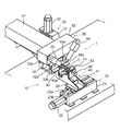
- FIG. 1 schematically illustrates an example of the configuration of the fracture start portion forming device 1 according to the present embodiment.
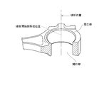
- FIG. 2 schematically illustrates an example of a perspective view showing a fracture start portion of the connecting rod rough material with a part of the through hole of the connecting rod rough material removed.
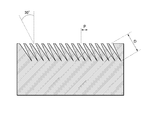
- FIG. 3 schematically illustrates an example of a cross-sectional view of the connecting rod rough material at the breaking position shown in FIG.
- FIG. 4 schematically illustrates an example of a waveform diagram of a laser pulse in the method for forming a fracture start portion according to the present embodiment.
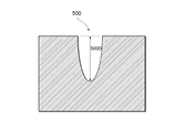
- FIG. 5 schematically illustrates an example of a cross-sectional view of the recessed portion 500 formed by the laser pulse according to the present embodiment.
- FIG. 6 schematically illustrates an example of the functional configuration of the laser beam irradiation device 50 according to the present embodiment.
- FIG. 7 schematically illustrates an example of a waveform diagram of a laser beam of a comparative example.
- FIG. 8 schematically illustrates an example of a cross-sectional view of the recessed portion 400 formed by the laser beam of the comparative example.
- FIG. 9 schematically illustrates an example of a graph showing the relationship between the frequency of the laser pulse and the processing depth of the recessed portion under a predetermined condition.
- the present embodiment an embodiment according to one aspect of the present invention (hereinafter, also referred to as “the present embodiment”) will be described with reference to the drawings.
- the embodiments described below are merely examples of the present invention in all respects. Needless to say, various improvements and modifications can be made without departing from the scope of the present invention. That is, in carrying out the present invention, a specific configuration according to the embodiment may be appropriately adopted.
- the data appearing in the present embodiment are described in natural language, but more specifically, the data is specified in a pseudo language, commands, parameters, machine language, etc. that can be recognized by a computer.
- FIG. 1 schematically illustrates an example of the configuration of the fracture start portion forming device 1 according to the present embodiment.
- the fracture start portion forming device 1 has a through hole in a part thereof, applies tensile stress to divide it into two parts from a specific fractured portion to form a half-split portion, and abuts the fracture surface of the half-split portion again. It is a device for forming a fracture start part in a metal part such as that used.
- the fracture start portion forming device 1 according to the present embodiment includes, for example, a laser light irradiation device 50.
- the laser light irradiation device 50 is an example of a device having a function of "irradiating a laser beam with a constant pulse" of the present invention. Further, the laser light irradiation device 50 may be an example of the "laser marker for printing on metal" of the present invention.
- a pulsed laser beam emitted by a laser light irradiation device 50 is irradiated to a predetermined fracture start portion forming position to start fracture of the metal component. The part can be formed.
- FIG. 2 schematically illustrates an example of a perspective view showing the fracture start portion of the connecting rod rough material, which is the raw material of the connecting rod, by removing a part of the through hole of the connecting rod rough material.
- the connecting rod is an example of the “metal part” of the present invention.
- Metal parts are not limited to connecting rods, but have through holes in some parts, and apply tensile stress to divide them into two parts from a specific fractured part to make a half-split part, and re-create the fracture surface of the half-split part. As long as the parts are used in contact with each other, for example, a bearing or a half-split spacer may be used. In the example of FIG.
- a fracture start portion is formed at a position extending from one end opening to the other end opening (break start portion forming position) on one side in the radial direction of the inner peripheral surface of the through hole of the connecting rod rough material. That is, at the fracture start portion forming position, a large number of recessed portions are formed as fracture start portions at a certain distance from each other.
- FIG. 3 schematically illustrates an example of a cross-sectional view of the connecting rod rough material at the breaking position.
- FIG. 3 shows an example of "a large number of recessed portions separated by a predetermined distance" of the present invention.
- the angle between the inner peripheral surface of the through hole of the connecting rod rough material and the irradiation direction of the laser pulse (the direction in which the recess is formed) is about 30 degrees, and the pitch P of the recess is about 0. It is .1 mm, and the depth D of the recessed portion is about 0.2 to 0.5 mm.
- FIG. 4 schematically illustrates an example of a waveform diagram of a laser pulse in the method for forming a fracture start portion according to the present embodiment.
- the horizontal axis represents time and the vertical axis represents output.
- the laser pulse shown in FIG. 4 is an example of the "constant pulse" of the present invention.
- a fracture start portion is formed by irradiating a metal part with a laser beam (laser pulse) composed of a plurality of pulses.
- Various parameters of the "constant pulse” (laser pulse output, laser pulse repetition frequency, laser pulse pulse width, etc.) are not particularly limited, but in the example shown in FIG. 4, for example, the laser pulse interval is about 15 ns.
- the repetition frequency is about 30 kHz
- the processing point output is about 16 W.
- FIG. 5 schematically illustrates an example of the recessed portion 500 formed by the laser pulse according to the present embodiment.
- the recessed portion 500 has a sufficient depth and no raised portion is formed in the periphery. This is due to the following reasons. That is, when the laser pulse is irradiated, a part of the metal on the surface of the metal part is liquefied and a fume is generated.
- a period in which the output of the laser light is low occurs between the individual laser pulses.
- the liquefied metal solidifies and the fume diffuses during the period when the output of the laser beam is low.
- the next laser pulse can reach the bottom of the recess 500 without being blocked by the liquefied metal or fume. Therefore, a recessed portion 500 having a sufficient depth and having no raised portion formed around the recessed portion 500 is formed.
- the method for forming the fracture start portion according to the present embodiment has higher accuracy in processing the recessed portion and is also excellent in energy efficiency as compared with the method for forming the fracture start portion in the comparative example.
- the break start portion forming device 1 includes a bed (base) 10 made of an elongated rectangular thick plate and an X-axis table device 20 provided with a slider 25 that can move in the longitudinal direction of the bed 10.
- a Y-axis table device 30 provided with a slider 35 vertically mounted on the upper surface of the bed 10 and movable in the vertical direction, and a conrod rough material support portion 40 attached to the slider 25 of the X-axis table device 20.
- the laser light irradiation device 50 and the like attached to the slider 35 of the Y-axis table device 30 are provided.
- the X-axis table device 20 includes a box-shaped housing 21, a servomotor 22 attached to one end of the housing 21, and two guide rails 23a and 23b attached to the upper surface of the housing 21 over the entire longitudinal direction of the housing.
- a slider 25 that can move on the guide rail, a ball screw (not shown) that is provided inside the housing and that moves the slider 25 in the X-axis direction according to the rotation of the servomotor 22 and the like are provided.
- the Y-axis table device 30 is attached to the housing 31 having a side view trapezoidal shape, the servomotor 32 attached to the upper surface of the housing 31, and the servomotor 32 attached to the upper surface of the bed 10 in a direction perpendicular to the upper surface of the bed 10 and parallel to each other. It is built into two guide rails 33a and 33b, a slider 35 that moves on the guide rail in the Y-axis direction, and a housing 31 that is provided inside the housing and moves the slider 35 in the Y-axis direction according to the rotation of the servomotor 32. It is equipped with a ball screw (not shown).
- the connecting rod rough material support portion 40 is separated from the bracket portion 41 attached to the slider 25 of the X-axis table device 20 at intervals corresponding to the large end portion and the small end portion of the connecting rod rough material above the bracket portion 41.
- the plates 42, 43 of the connecting rod rough material support portion 40 are provided with seat surfaces (spacers) 42a, 43a having a constant thickness for arranging the connecting rod rough material in parallel with the upper surface of the bed 10.
- the laser light irradiation device 50 is attached to both ends of the laser light emitting unit 51, the laser light guiding unit 52 that guides the laser light excited by the laser light transmitting unit 51 through a predetermined optical path, and the laser light guiding unit 52. It is composed of two laser light irradiation units 55 and 56 attached to the laser light guidance unit 52 in a state of being formed at a constant angle with each other.
- the laser light irradiation units 55 and 56 are attached to the side surfaces of the laser light guidance unit 52, and the tip portions 55a and 56a that irradiate the laser light so that the laser light emitted by the laser light irradiation units 55 and 56 intersect with each other. They are arranged at a certain angle.
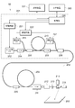
- FIG. 6 schematically illustrates an example of the functional configuration of the laser beam irradiation device 50 according to the present embodiment.
- the laser light irradiation device 50 according to the present embodiment may have a function as a laser marker for printing on metal. That is, as described below, according to the method for forming a fracture start portion of a metal part according to the present embodiment, even a simple laser light irradiation device 50 used as a laser marker does not require other incidental equipment or the like. With a simple structure, it is possible to form a fracture start portion on a metal part.
- the laser light irradiation device 50 includes a controller 201 and a marker head 202.
- the controller 201 and the marker head 202 correspond to the above-mentioned laser light emitting unit 51, the laser light guiding unit 52, the laser light irradiating unit 55, 56, and the like.
- the laser light irradiation device 50 typically includes a MOPA (Master Oscillator and Power Amplifier) type fiber amplifier.
- the laser beam irradiator 50 includes a two-stage fiber amplifier.
- the controller 201 includes an optical amplification fiber 210, a seed laser diode (LD) 202, an excitation laser diode 203, 207, an isolator 204, 206, a combiner 205, 208, and a drive circuit 221. , 222 and a control unit 220.
- LD seed laser diode
- the marker head 202 includes an optical amplification fiber 209, an optical coupler 216, an isolator 211, a beam expander 212, a Z-axis scanning lens 213, and galvano scanners 214 and 215.
- the laser diode may be simply referred to as "LD".
- the optical amplifier fiber 210, the seed LD202, and the excitation LD203 are basic components of the MOPA type fiber amplifier.
- the optical amplification fiber 210 includes a core to which a rare earth element which is an optical amplification component is added, and a clad provided around the core.
- the optical amplification fiber 209 includes a core to which a rare earth element which is an optical amplification component is added, and a clad provided around the core.
- the type of rare earth element added to the cores of the optical amplifier fibers 210 and 209 is not particularly limited, but for example, Yb (ytterbium), Er (erbium), Nd (neodymium) and the like can be used. In the present embodiment, a case where an optical amplifier fiber to which Yb is added as a rare earth element is used will be illustrated.
- the optical amplifier fibers 210 and 209 may be, for example, a single clad fiber in which one layer of clad is provided around the core, or a double clad fiber in which two layers of clad are provided around the core.
- the optical amplification fiber 210 amplifies the seed light from the seed LD202 by the excitation light from the excitation LD203. That is, in the MOPA type fiber amplifier, the excitation light from the excitation LD203 and the pulsed seed light from the seed LD202 are given to the optical amplification fiber 210.
- the excitation light incident on the optical amplification fiber 210 is absorbed by the atoms of the rare earth element contained in the core, and the atoms are excited.
- the seed light propagates through the core of the optical amplification fiber 210 in a state where the atoms are excited, the atoms excited by the seed light cause stimulated emission, so that the seed light is amplified. In this way, the optical amplification fiber 210 amplifies the seed light by using the excitation light.
- the seed LD202 is a laser light source and is a seed light source that generates seed light.
- the wavelength of the seed light is selected, for example, from the range of 1000 to 1100 nm.
- the drive circuit 21 pulse-drives the seed LD202 by repeatedly applying a pulsed current to the seed LD202 in accordance with a command from the control unit 220. That is, the seed LD202 emits pulsed seed light.
- the seed light emitted from the seed LD202 passes through the isolator 204 and then enters the optical amplification fiber 210.
- the isolator 204 has a function of passing light in only one direction and blocking light incident in the opposite direction.
- the isolator 204 allows the seed light from the seed LD202 to pass through and blocks the return light from the optical amplification fiber 210.
- the excitation LD203 is a laser light source, and is an excitation light source that generates excitation light for exciting the atoms of rare earth elements added to the core of the optical amplification fiber 210.
- the wavelength of the excitation light is set to, for example, 915 ⁇ 10 nm.
- the excitation LD203 is driven by the drive circuit 222.
- the seed light from the seed LD202 and the excitation light from the excitation LD203 are combined by the combiner 205 and incident on the optical amplification fiber 210.
- the optical amplification fiber 210 is a single clad fiber, both the seed light and the excitation light are incident on the core.
- the optical amplification fiber 210 is a double clad fiber, the seed light is incident on the core and the excitation light is incident on the first clad.
- the first clad of the double clad fiber functions as a waveguide for excitation light. In the process of the excitation light incident on the first clad propagating through the first clad, the rare earth element in the core is excited by the mode of passing through the core.
- the laser light amplified by the optical amplification fiber 210 passes through the isolator 206 and is combined with the excitation light from the excitation LD207 in the combiner 208.
- the excitation LD207 generates excitation light for exciting the atoms of the rare earth element added to the core of the optical amplifier fiber 209.
- the excitation LD207 is driven by a drive circuit 222.
- the optical amplification fiber 209 is optically coupled to the fiber from the controller 201 by the optical coupler 216.
- the laser light amplified by the optical amplification fiber 210 is further amplified by the excitation light from the excitation LD207 inside the optical amplification fiber 209.
- the laser light emitted from the optical amplifier fiber 209 passes through the isolator 211.
- the isolator 211 passes the laser light amplified by the optical amplifier fiber 209 and emitted from the optical amplifier fiber 209, and blocks the laser light returning to the optical amplifier fiber 209.
- the beam diameter of the laser beam that has passed through the isolator 211 is expanded by the beam expander 212.
- the Z-axis scanning lens 213 scans the laser beam in the Z-axis direction (that is, in the vertical direction).
- the galvano scanners 214 and 215 scan the laser beam in the X-axis direction and the Y-axis direction, respectively. As a result, the laser beam is scanned in the two-dimensional direction on the surface of the object to be processed 250 such as the connecting rod rough material.
- the marker head 202 may include other optical components such as an f ⁇ lens for condensing laser light.
- the laser beam that is, the laser pulse from the optical amplifier in the two-dimensional direction on the surface of the object to be processed 250, the surface of the object to be processed 250 made of resin, metal or the like is processed.
- the optical amplifier is configured to increase the excitation light in the first stage amplification (optical amplification in the controller 201).
- the optical amplifier fiber 209 may be omitted from the marker head 202.
- the control unit 220 mainly controls the generation of light by the seed LD202 (seed light source) and the excitation LD203 (excitation light source). More specifically, the control unit 220 receives a command required for scanning the laser beam from the host device 300. Further, the control unit 220 receives a setting from the user via the setting device 301. The control unit 220 controls the drive circuits 221,222 and the galvano scanners 214, 215 and the like according to the user operation from the setting device 301.
- the control unit 220 may use any hardware as long as it is configured to give a control command.
- the control unit 220 may be implemented by using a computer that executes a predetermined program.
- a computer that executes a predetermined program.
- a personal computer can be used as the setting device 301.
- the personal computer may be provided with a mouse, a keyboard, a touch panel, or the like as an input unit.
- optical elements such as the seed LD202, the excitation LD203,7, and the isolators 204, 6, 11 can change depending on the temperature. Therefore, it is more preferable to provide the laser light irradiation device 50 with a temperature controller for keeping the temperature of these optical elements constant.
- the user can set various parameters as processing conditions independently of each other.
- the parameters are not limited, but as examples, the shape of the laser pulse, the output of the laser pulse, the repetition frequency of the laser pulse, the pulse width of the laser pulse, the laser pulse irradiation time in one recess, and the correction values of various parameters (X correction).
- a value, a Y correction value, a Z correction value, a ⁇ X correction value, a ⁇ Y correction value, a ⁇ Z correction value, etc.) may be included.
- the breaking start portion is formed by locating the slider 25 of the X-axis table device 20 of the breaking start portion forming device 1 at one side end of the guide rails 23a and 23b.
- the connecting rod rough material is attached to a predetermined attachment portion of the connecting rod rough material support portion 40.
- the X-axis table device 20 is driven to move the connecting rod rough material support portion 40 to the lower vicinity of the laser beam irradiation portions 55 and 56.
- one of the laser light irradiation parts 55 and 56 is placed in the radial direction of one of the inner peripheral surfaces of the through holes of the connecting rod rough material. Position it to the side. At this time, the laser beam of the laser beam irradiation portions 55 and 56 is adjusted so that the focus of the laser beam is aligned with the inner peripheral surface of the through hole of the connecting rod rough material.
- the processing conditions include, for example, the shape of the laser pulse, the output of the laser pulse, the repetition frequency of the laser pulse, the pulse width of the laser pulse, the laser pulse irradiation time in one recess, and the correction values (X correction value) of various parameters. , Y correction value, Z correction value, ⁇ X correction value, ⁇ Y correction value, ⁇ Z correction value, etc.) and the like may be included.
- the laser light irradiating unit (for example, the laser light irradiating unit 55) emits the laser light with a predetermined pulse set as described above by transmitting the laser light transmitting unit 51. Irradiate the inner peripheral surface of the through hole of the material. At this time, for example, after irradiating one recessed portion with a laser pulse a predetermined number of times, the recessed portion may be sequentially formed by irradiating the next recessed portion with a laser pulse.
- the focal position of the laser light irradiation portion is located at the adjacent recess forming position.
- irradiation of the laser pulse to the adjacent recessed portion forming position is executed a predetermined number of times.
- a large number of recesses for example, FIG. 2 etc.
- the fracture start portion forming position for example, FIG. 2 etc.
- FIG. 3 etc. are formed as a fracture start portion at a certain distance from each other.
- FIG. 7 schematically illustrates an example of the waveform diagram of the laser beam of the comparative example.
- the horizontal axis represents time and the vertical axis represents output.
- the waveform diagram of the laser beam of the comparative example does not repeat the increase and decrease unlike the laser pulse according to the present embodiment, and the output increases from 0 to the peak value over a predetermined period. After that, it drops from the peak value to 0 over a predetermined period.
- FIG. 8 schematically illustrates an example of a cross-sectional view of the recessed portion 400 formed by the laser beam of the comparative example, and FIG. 8 is a cross-sectional view of the recessed portion 400 formed by the laser pulse according to the present embodiment. An example is schematically illustrated.
- the recessed portion 400 formed by the laser beam of the comparative example does not have a sufficient depth of 400D, and a raised portion 401 is formed in the periphery.
- a part of the metal on the surface of the metal part is liquefied and fume is generated.
- the laser beam of the comparative example shows a continuous change that is not pulsed. Therefore, after the metal on the surface of the metal part is liquefied and fume is generated, a part of the laser beam irradiated to the metal part is further blocked by the fume or the liquefied metal, so that the metal part is further blocked. Unable to reach the solid part of.
- the energy of the laser beam is not sufficiently applied to the metal part, and the recessed portion 400 does not have a sufficient depth. Further, the liquefied metal is pushed away to the periphery of the recess 400 by being irradiated with the laser beam. Therefore, the liquefied and pushed-out metal is extruded around the recessed portion 400, and is eventually cooled and solidified to form a raised portion 401.
- the liquefied metal solidifies and fume during the period between the individual laser pulses. Has a sufficient depth and a raised portion is not formed in the periphery because of the diffusion.
- the method for forming the fracture start portion according to the present embodiment has higher accuracy in processing the recessed portion and is also excellent in energy efficiency as compared with the method for forming the fracture start portion in the comparative example.
- FIG. 9 schematically illustrates an example of a graph showing the relationship between the frequency of the laser pulse and the processing depth of the recessed portion under a predetermined condition.
- the laser power is 80%
- the pitch of the recessed portion is 0.1 mm
- the number of laser pulses irradiating the recessed portion is 900.
- the processing depth increases as the frequency increases in the frequency range of 0 to about 30 kHz, and the processing depth is about 0.5 mm when the frequency is about 30 kHz. Further, in the frequency range of about 30 to about 50 kHz, the higher the frequency, the smaller the machining depth, and when the frequency is about 50 kHz, the machining depth is about 0.1 mm. Further, in the range of the frequency of about 50 kHz or more, the processing depth gradually decreases as the frequency increases.
- the reason why the graph shown in FIG. 9 shows the above-mentioned aspect can be explained as follows. That is, when the laser pulse is applied to the metal part, the energy of the laser pulse is given to the metal part. This creates fume and warms the metal, some of which reaches its melting point and liquefies.
- the high frequency region the residual amount of fume and liquefied metal generated by the previous laser pulse increases, which increases the proportion of the laser pulse that prevents it from reaching the bottom of the recess.
- the machining depth decreases as the frequency increases.
- the metal is cooled for a relatively long time.
- a metal that is below the melting point but has been warmed to near the melting point is sufficiently cooled during the period between the laser pulses, and the case where the metal does not reach the melting point even if the laser pulse is repeatedly irradiated increases.
- the machining depth decreases as the frequency decreases.
- the frequency is preferably in the range of 10 to 50 kHz, more preferably in the range of 10 to 40 kHz, and more preferably in the range of 20 to 35 kHz.
- the irradiation of the laser pulse is moved so as to sequentially form the recessed portions. That is, at the position where the breaking start portion of the connecting rod rough material is formed, a recessed portion is formed by irradiating one location with a laser pulse a predetermined number of times, and then the irradiation position of the laser pulse is moved to another location. A recessed portion is formed by irradiating the other portion with a laser pulse a predetermined number of times.
- the present invention is not limited to this, and a large number of recessed portions may be formed by scanning the irradiation position of the laser pulse within the fracture start portion forming position of the connecting rod rough material, for example.
- the processing width can be adjusted simply by setting a numerical value, which facilitates support for high-mix production.
- the position where the breaking start portion of the connecting rod rough material is formed is divided into a plurality of sections, and then the irradiation position of the laser pulse is scanned in each section, so that the recessed portion is sequentially formed for each section. It may be formed. As a result, the time for adjusting the focal position of the laser pulse can be shortened.
- [Appendix 1] A method for forming a fracture start portion of a metal part having a predetermined through hole on the inner peripheral surface of the through hole, from one opening of the through hole to the other opening. A large number of recesses (500) separated by a predetermined distance are formed by moving the irradiation position of the laser beam along the path while irradiating the laser beam with a constant pulse along the path on the inner peripheral surface of the through hole to be connected.
- a method for forming a fracture start portion of a metal part which comprises step S4 of forming.
- one recess (500) is formed by irradiating the first portion of the path with a laser beam a predetermined number of times with a constant pulse.
- the step (S4) of forming a large number of recesses (500) includes scanning the irradiation position of the laser beam within a predetermined range included in the path while irradiating the laser beam with a constant pulse.
- Appendix 4 The method for forming a fracture start portion of a metal part according to any one of Appendix 1 to 3, wherein the laser light is supplied by a laser marker (50) for printing on a metal.
- Laser light transmitter 52 ... Laser light guidance unit 55, 56... Laser light irradiation unit 55a, 56a... Tip part 201... Controller 202... Marker head 203, 207... Excitation laser diode 204, 206, 211... Isolator 205, 208... Combiner 209, 210... Optical amplification fiber 216 ... Optical coupler 212 ... Beam expander 213 ... Z-axis scanning lens 214, 215 ... Galvano scanner 220 ... Control unit 221, 222 ... Drive circuit 250 ... Machining object 300 ... Upper device 301 ... Setting device 400 ... Recess Part 401 ... Raised part 500 ... Recessed part
Landscapes
- Engineering & Computer Science (AREA)
- Physics & Mathematics (AREA)
- Optics & Photonics (AREA)
- Plasma & Fusion (AREA)
- Mechanical Engineering (AREA)
- Laser Beam Processing (AREA)
Abstract
簡易な構成で金属製部品の破断開始部を形成する方法を提供する。本発明の一側面に係る金属製部品の破断開始部形成方法は、所定の貫通孔を有する金属製部品の当該貫通孔内周面に破断開始部を形成する金属製部品の破断開始部形成方法であって、貫通孔の一方の開口部から他方の開口部までを結ぶ貫通孔内周面上の経路に沿って、レーザ光を一定のパルスで照射しながらレーザ光の照射位置を経路に沿って移動させることで、所定距離離間した多数の凹み部を形成するステップを含む。
Description
本発明は、例えば自動車のコネクティングロッド(以下、単に「コンロッド」とする)などの金属製部品の破断開始部を形成する金属製部品の破断開始部形成方法に関する。
金属製部品を引張り破断して半割りされた部品を再び組み合せた一対の製品として使用する場合がある。このような部品の一例として自動車用部品として知られるコネクティングロッド(以下、単に「コンロッド」とする)があげられる。
例えば特許文献1には、金属製部品の破断開始部に対応する部分に溝部をブローチ加工によって形成するステップと、溝部の底の部分に複数の凹み部を互いに所定間隔隔てて形成するステップとを有する金属製部品の破断開始部形成方法が開示されている。
例えば特許文献2には、焦点を貫通孔内周面から一定量だけデフォーカスして貫通孔内周面に照射すると同時に、アシストガスをレーザ光照射位置に供給することで凹み部を形成し、レーザ光を一定のパルスで貫通孔内周面に照射しながらレーザ光を貫通孔内周面の一側開口部から他側開口部まで所定の速度で直線的に移動させる金属製部品の破断開始部形成方法が開示されている。
しかしながら、特許文献1に記載の方法では、レーザ加工の前にブローチ等の機械(刃物)加工が必要となる。また、特許文献2に記載の方法では、加工中に除去物を吹き飛ばすためのアシストガスが必要となる。
本発明は、一側面では、このような実情を鑑みてなされたものであり、その目的は、簡易な構成で金属製部品の破断開始部を形成する方法を提供することである。
本発明は、上述した課題を解決するために、以下の構成を採用する。
すなわち、本発明の一側面に係る金属製部品の破断開始部形成方法は、所定の貫通孔を有する金属製部品の当該貫通孔内周面に破断開始部を形成する金属製部品の破断開始部形成方法であって、貫通孔の一方の開口部から他方の開口部までを結ぶ貫通孔内周面上の経路に沿って、レーザ光を一定のパルスで照射しながらレーザ光の照射位置を経路に沿って移動させることで、所定距離離間した多数の凹み部を形成するステップを含む。
上記構成では、個々のレーザパルスによって金属が液化し且つヒュームが生じても、レーザ光の出力が低い期間において、液化した金属は凝固しヒュームは拡散する。そのため、レーザパルスが、液化した金属やヒュームに遮られることなく、金属製部品に到達することができる。よって、十分な深さを有し且つ周辺に盛り上がり部が形成されない凹み部から成る破断開始部が形成される。
上記一側面に係る金属製部品の破断開始部形成方法において、多数の凹み部を形成するステップは、経路の第1箇所にレーザ光を一定のパルスで所定回数だけ照射することにより一の凹み部を形成した後、経路の第2箇所にレーザ光を一定のパルスで所定回数だけ照射することにより他の凹み部を形成することを含んでもよい。当該構成によれば、加工幅を数値設定するだけで調節できるため多品種生産への対応が容易となる。
上記一側面に係る金属製部品の破断開始部形成方法において、多数の凹み部を形成するステップは、レーザ光を一定のパルスで照射しながらレーザ光の照射位置を経路に含まれる所定の範囲内で走査させることを含んでもよい。当該構成によれば、レーザパルスの焦点位置の調節の時間が短縮できる。
上記一側面に係る金属製部品の破断開始部形成方法において、レーザ光は、金属に印字するためのレーザマーカによって供給されてもよい。当該構成によれば、レーザマーカという簡易なレーザ光供給源によって、金属製部品に破断開始部を形成することが可能となる。
本発明によれば、簡易な構成で金属製部品の破断開始部を形成する方法を提供することができる。
以下、本発明の一側面に係る実施の形態(以下、「本実施形態」とも表記する)を、図面に基づいて説明する。ただし、以下で説明する本実施形態は、あらゆる点において本発明の例示に過ぎない。本発明の範囲を逸脱することなく種々の改良や変形を行うことができることは言うまでもない。つまり、本発明の実施にあたって、実施形態に応じた具体的構成が適宜採用されてもよい。なお、本実施形態において登場するデータを自然言語により説明しているが、より具体的には、コンピュータが認識可能な疑似言語、コマンド、パラメータ、マシン語等で指定される。
§1 適用例
まず、図1を用いて、本発明が適用される場面の一例について説明する。図1は、本実施の形態に係る破断開始部形成装置1の構成の一例を模式的に例示する。破断開始部形成装置1は、一部に貫通孔を有し、引張り応力をかけて特定の破断部から2分割して半割り部をつくり、当該半割り部の破断面を再び当接させて使用するような金属製部品に、破断開始部を形成するための装置である。本実施の形態に係る破断開始部形成装置1は、例えば、レーザ光照射装置50を有する。レーザ光照射装置50は、本発明の「レーザ光を一定のパルスで照射」する機能を有する装置の一例である。また、レーザ光照射装置50は、本発明の「金属に印字するためのレーザマーカ」の一例であってもよい。本実施の形態に係る金属製部品の破断開始部形成方法では、例えばレーザ光照射装置50が発するパルス状のレーザ光を所定の破断開始部形成位置に照射することにより、金属製部品に破断開始部を形成することができる。
まず、図1を用いて、本発明が適用される場面の一例について説明する。図1は、本実施の形態に係る破断開始部形成装置1の構成の一例を模式的に例示する。破断開始部形成装置1は、一部に貫通孔を有し、引張り応力をかけて特定の破断部から2分割して半割り部をつくり、当該半割り部の破断面を再び当接させて使用するような金属製部品に、破断開始部を形成するための装置である。本実施の形態に係る破断開始部形成装置1は、例えば、レーザ光照射装置50を有する。レーザ光照射装置50は、本発明の「レーザ光を一定のパルスで照射」する機能を有する装置の一例である。また、レーザ光照射装置50は、本発明の「金属に印字するためのレーザマーカ」の一例であってもよい。本実施の形態に係る金属製部品の破断開始部形成方法では、例えばレーザ光照射装置50が発するパルス状のレーザ光を所定の破断開始部形成位置に照射することにより、金属製部品に破断開始部を形成することができる。
図2は、コンロッドの原材料であるコンロッド粗材の破断開始部を、コンロッド粗材の貫通孔の一部を削除して示した斜視図の一例を模式的に例示する。ここで、コンロッドは、本発明の「金属製部品」の一例である。「金属製部品」は、コンロッドに限らず、一部に貫通孔を有し、引張り応力をかけて特定の破断部から2分割して半割り部をつくり、当該半割り部の破断面を再び当接させて使用する部品であれば、例えばベアリングや半割りスペーサ等であってもよい。図2の例では、コンロッド粗材の貫通孔の内周面の半径方向一側において一端開口部から他端開口部にわたる位置(破断開始部形成位置)に破断開始部が形成される。すなわち、破断開始部形成位置において、多数の凹み部が破断開始部として互いに一定距離離間して形成される。
図3は、破断位置におけるコンロッド粗材の断面図の一例を模式的に例示する。ここで、図3には、本発明の「所定距離離間した多数の凹み部」の一例が示されている。図3の例では、コンロッド粗材の貫通孔の内周面と、レーザパルスの照射方向(凹み部が形成される方向)との角度は約30度であり、凹み部のピッチPは約0.1mmであり、凹み部の深さDは約0.2~0.5mmである。
図4は、本実施の形態に係る破断開始部形成方法におけるレーザパルスの波形図の一例を模式的に例示する。図4の横軸は時間、縦軸は出力を示す。図4に示すレーザパルスは、本発明の「一定のパルス」の一例である。本実施の形態に係る破断開始部形成方法においては、例えば図4に示すような、複数のパルスからなるレーザ光(レーザパルス)を金属製部品に照射することによって破断開始部が形成される。「一定のパルス」の各種パラメータ(レーザパルスの出力、レーザパルスの繰り返し周波数、レーザパルスのパルス幅等)は特に限定されないが、例えば図4に示す例では、レーザパルスの間隔は約15nsであり、繰り返し周波数は約30kHzであり、加工点出力は約16Wである。
図5は、本実施の形態に係るレーザパルスによって形成された凹み部500の一例を模式的に例示する。図5に示す凹み部500の例では、十分な深さを有し且つ周辺に盛り上がり部が形成されない。これは次のような理由による。すなわち、レーザパルスが照射されると、金属製部品の表面の金属の一部が液化すると共にヒュームが発生する。ここで、本実施の形態に係るレーザパルスでは、個々のレーザパルス間にレーザ光の出力が低い期間(レーザ光の出力が0である期間を含む)が生じる。個々のレーザパルスによって金属が液化し且つヒュームが生じても、当該レーザ光の出力が低い期間において、液化した金属は凝固し、ヒュームは拡散する。次のレーザパルスは、液化した金属やヒュームに遮られることなく、凹み部500の底に到達することができる。そのため、十分な深さを有し且つ周辺に盛り上がり部が形成されない凹み部500が形成される。
以上のとおり、本実施の形態に係る破断開始部の形成方法は、比較例の破断開始部の形成方法と比較して、凹み部の加工の精度が高く、エネルギー効率にも優れる。
§2 構成例
<破断開始部形成装置>
図1に示す例では、破断開始部形成装置1は、細長矩形状の厚板からなるベッド(土台)10と、ベッド10の長手方向に移動可能なスライダ25を備えたX軸テーブル装置20と、ベッド10の上面に垂直方向に設置されて垂直方向への移動可能なスライダ35を備えたY軸テーブル装置30と、X軸テーブル装置20のスライダ25に取り付けられたコンロッド粗材支持部40と、Y軸テーブル装置30のスライダ35に取り付けられたレーザ光照射装置50等を備えている。
<破断開始部形成装置>
図1に示す例では、破断開始部形成装置1は、細長矩形状の厚板からなるベッド(土台)10と、ベッド10の長手方向に移動可能なスライダ25を備えたX軸テーブル装置20と、ベッド10の上面に垂直方向に設置されて垂直方向への移動可能なスライダ35を備えたY軸テーブル装置30と、X軸テーブル装置20のスライダ25に取り付けられたコンロッド粗材支持部40と、Y軸テーブル装置30のスライダ35に取り付けられたレーザ光照射装置50等を備えている。
X軸テーブル装置20は、箱型のハウジング21と、ハウジング21の一端部に取り付けられたサーボモータ22と、ハウジング21の上面にハウジング長手方向全体にわたって取り付けられた2本のガイドレール23a,23bと、ガイドレール上を移動可能なスライダ25と、ハウジング内部に備えられかつサーボモータ22の回転に応じてスライダ25をX軸方向に移動させるボールねじ(図示せず)等を備えている。
また、Y軸テーブル装置30は、側面視台形形状のハウジング31と、ハウジング31の上面に取り付けられたサーボモータ32と、ベッド10の上面と垂直方向をなしてハウジング31に互いに平行に取り付けられた2本のガイドレール33a,33bと、ガイドレール上をY軸方向に動くスライダ35と、ハウジング内部に備えられサーボモータ32の回転に応じてスライダ35をY軸方向に移動させるハウジング31に内蔵されたボールネジ(図示せず)とを備えている。
コンロッド粗材支持部40は、X軸テーブル装置20のスライダ25に取り付けられたブラッケット部41と、ブラッケット部41の上方においてコンロッド粗材の大端部と小端部に対応する間隔で離間して配置されたプレート42,43と、コンロッド粗材の小端部を押さえ付ける押さえ部44と、コンロッド粗材の押さえ部44をコンロッド粗材小端部に向かって押し付けるエアシリンダ45と、コンロッド粗材大端部の周囲所定部分を拘束する拘束部(図示せず)とを備えている。なお、コンロッド粗材支持部40のプレート42,43にはコンロッド粗材をベッド10の上面に対して平行に配置するための一定厚さの座面(スペーサ)42a,43aが取り付けられている。
レーザ光照射装置50は、レーザ光発信部51と、レーザ光発信部51によって励起されたレーザ光を所定の光路を介して誘導するレーザ光誘導部52と、レーザ光誘導部52の両端に取り付けられ、互いに一定の角度をなした状態でレーザ光誘導部52に取り付けられた2つのレーザ光照射部55,56とからなる。レーザ光照射部55,56はレーザ光誘導部52の側面に取り付けられ、互いのレーザ光照射部55,56が照射するレーザ光が交差するようにレーザ光を照射する先端部55a,56aが互いに一定の角度をなして配置されている。
<レーザ光照射装置>
次に、図6を用いて、本実施の形態に係るレーザ光照射装置50の機能構成の一例について説明する。図6は、本実施の形態に係るレーザ光照射装置50の機能構成の一例を模式的に例示する。本実施の形態に係るレーザ光照射装置50は、金属に印字するためのレーザマーカとしての機能を有していてもよい。すなわち、以下で説明するとおり、本実施の形態に係る金属製部品の破断開始部形成方法によれば、レーザマーカとして用いられる簡易なレーザ光照射装置50によっても、他の付帯設備等を必要とせずに簡易な構成によって、金属製部品に破断開始部を形成することが可能となる。
次に、図6を用いて、本実施の形態に係るレーザ光照射装置50の機能構成の一例について説明する。図6は、本実施の形態に係るレーザ光照射装置50の機能構成の一例を模式的に例示する。本実施の形態に係るレーザ光照射装置50は、金属に印字するためのレーザマーカとしての機能を有していてもよい。すなわち、以下で説明するとおり、本実施の形態に係る金属製部品の破断開始部形成方法によれば、レーザマーカとして用いられる簡易なレーザ光照射装置50によっても、他の付帯設備等を必要とせずに簡易な構成によって、金属製部品に破断開始部を形成することが可能となる。
レーザ光照射装置50は、コントローラ201と、マーカーヘッド202とを含む。コントローラ201と、マーカーヘッド202とは、上述したレーザ光発信部51と、レーザ光誘導部52と、レーザ光照射部55、56等に対応する。
レーザ光照射装置50は、典型的には、MOPA(Master Oscillator and Power Amplifier)方式のファイバ増幅器を含む。この実施の形態では、レーザ光照射装置50は、2段のファイバ増幅器を含む。より具体的には、コントローラ201は、光増幅ファイバ210と、シード用レーザダイオード(LD)202と、励起用レーザダイオード203,207と、アイソレータ204,206と、コンバイナ205,208と、駆動回路221,222と、制御部220とを含む。
マーカーヘッド202は、光増幅ファイバ209と、光カプラ216と、アイソレータ211と、ビームエキスパンダ212と、Z軸走査レンズ213と、ガルバノスキャナ214,215とを含む。なお、以下の説明においては、レーザダイオードを単に「LD」と表記することもある。
光増幅ファイバ210、シード用LD202、および励起用LD203は、MOPA方式のファイバ増幅器の基本的な構成要素である。光増幅ファイバ210は、光増幅成分である希土類元素が添加されたコア、およびそのコアの周囲に設けられるクラッドを含む。光増幅ファイバ209は、光増幅ファイバ210と同じく、光増幅成分である希土類元素が添加されたコア、およびそのコアの周囲に設けられるクラッドを含む。
光増幅ファイバ210,209のコアに添加される希土類元素の種類は、特に限定されないが、例えば、Yb(イッテルビウム)、Er(エルビウム)、Nd(ネオジム)などを用いることができる。本実施の形態においては、希土類元素としてYbが添加された光増幅ファイバを用いる場合について例示する。光増幅ファイバ210,209は、例えば、コアの周囲に一層のクラッドが設けられたシングルクラッドファイバでもよいし、コアの周囲に二層のクラッドが設けられたダブルクラッドファイバでもよい。
光増幅ファイバ210は、シード用LD202からのシード光を励起用LD203からの励起光によって増幅する。すなわち、MOPA方式のファイバ増幅器では、励起用LD203からの励起光およびシード用LD202からのパルス状のシード光が、光増幅ファイバ210へ与えられる。光増幅ファイバ210に入射した励起光は、コアに含まれる希土類元素の原子に吸収され、原子の励起を生じる。原子の励起が生じた状態で、シード光が光増幅ファイバ210のコアを伝搬すると、シード光により励起された原子が誘導放出を生じるため、シード光が増幅される。このように、光増幅ファイバ210は、励起光を用いてシード光を増幅することになる。
シード用LD202は、レーザ光源であり、シード光を発生するシード光源である。シード光の波長は、例えば、1000~1100nmの範囲から選択される。駆動回路21は、制御部220からの指令に従って、シード用LD202にパルス状の電流を繰り返して印加することにより、シード用LD202をパルス駆動する。すなわち、シード用LD202はパルス状のシード光を出射する。
シード用LD202から出射されるシード光は、アイソレータ204を通過した後に、光増幅ファイバ210へ入射する。アイソレータ204は、光を一方向のみに通過させ、それとは逆方向に入射する光を遮断する機能を有する。アイソレータ204は、シード用LD202からのシード光を通過させるとともに、光増幅ファイバ210からの戻り光を遮断する。これによって、光増幅ファイバ210からの戻り光がシード用LD202に入射するのを防止することができる。これは、光増幅ファイバ210からの戻り光がシード用LD202に入射した場合には、シード用LD202が損傷するおそれがあるからである。
励起用LD203は、レーザ光源であり、光増幅ファイバ210のコアに添加された希土類元素の原子を励起するための励起光を発生する励起光源である。希土類元素としてYbを添加した場合、励起光の波長は、例えば915±10nmに設定される。励起用LD203は、駆動回路222によって駆動される。
シード用LD202からのシード光と励起用LD203からの励起光とは、コンバイナ205により結合されて光増幅ファイバ210に入射する。光増幅ファイバ210がシングルクラッドファイバである場合には、シード光および励起光はいずれもコアに入射する。これに対し、光増幅ファイバ210がダブルクラッドファイバである場合には、シード光はコアに入射し、励起光は第1クラッドに入射する。ダブルクラッドファイバの第1クラッドは励起光の導波路として機能する。第1クラッドに入射した励起光が第1クラッドを伝搬する過程で、コアを通過するモードによりコア中の希土類元素が励起される。
光増幅ファイバ210で増幅されたレーザ光は、アイソレータ206を通り、コンバイナ208において、励起用LD207からの励起光と結合される。励起用LD207は、光増幅ファイバ209のコアに添加された希土類元素の原子を励起するための励起光を発生する。励起用LD207は、駆動回路222によって駆動される。
光増幅ファイバ209は、光カプラ216によって、コントローラ201からのファイバに光学的に結合される。光増幅ファイバ210によって増幅されたレーザ光は、光増幅ファイバ209の内部において、励起用LD207からの励起光によってさらに増幅される。
光増幅ファイバ209から出射されたレーザ光は、アイソレータ211を通過する。アイソレータ211は、光増幅ファイバ209で増幅され、かつ光増幅ファイバ209から出射されたレーザ光を通過させるとともに、光増幅ファイバ209に戻るレーザ光を遮断する。
アイソレータ211を通過したレーザ光は、ビームエキスパンダ212によって、そのビーム径が拡大される。Z軸走査レンズ213は、レーザ光をZ軸方向(すなわち上下方向)に走査する。ガルバノスキャナ214,215は、レーザ光を、X軸方向およびY軸方向にそれぞれ走査する。これにより、レーザ光がコンロッド粗材等の加工対象物250の表面において、二次元方向に走査される。なお、図示しないが、レーザ光を集光するためのfθレンズ等の他の光学部品がマーカーヘッド202に含まれてもよい。
加工対象物250の表面上でレーザ光、すなわち光増幅装置からのレーザパルスを二次元方向に走査することにより、樹脂、金属等を素材とする加工対象物250の表面に加工が施される。
本実施の形態では、光増幅装置は、1段目の増幅(コントローラ201における光増幅)において励起光を増大するように構成される。しかしながら、マーカーヘッド202が光増幅を行うことは、必ずしも必須ではない。すなわちマーカーヘッド202から光増幅ファイバ209が省略されてもよい。
制御部220は、主として、シード用LD202(シード光源)および励起用LD203(励起光源)による光の発生を制御する。より具体的には、制御部220は、上位装置300から、レーザ光の走査のために必要な指令を受信する。さらに、制御部220は、設定装置301を介して、ユーザからの設定を受付ける。制御部220は、設定装置301からのユーザ操作に従って、駆動回路221,222を制御するとともに、ガルバノスキャナ214,215等を制御する。
制御部220は、制御指令を与える構成であれば、どのようなハードウェア用いてもよい。例えば、所定のプログラムを実行するコンピュータを用いて、制御部220を実装してもよい。設定装置301としては、例えば、パーソナルコンピュータを使用することができる。パーソナルコンピュータは、入力部として、マウス、キーボード、タッチパネル等を備えることができる。
シード用LD202、励起用LD203,7、アイソレータ204,6,11などの光学素子の特性は、温度に依存して変化し得る。そのため、これらの光学素子の温度を一定に保つための温度コントローラをレーザ光照射装置50に設けることがより好ましい。
本実施の形態に係るレーザ光照射装置50に対して、ユーザは、加工条件としての各種パラメータを互いに独立に設定することができる。当該パラメータは、限定ではなく例として、レーザパルスの形状、レーザパルスの出力、レーザパルスの繰り返し周波数、レーザパルスのパルス幅、1つの凹み部におけるレーザパルス照射時間、各種パラメータの補正値(X補正値、Y補正値、Z補正値、θX補正値、θY補正値、θZ補正値等)等を含んでもよい。
§3 金属製部品の破断開始部形成方法の一例
次に、本実施の形態に係る金属製部品の破断開始部形成方法について説明する。以下では、上述した破断開始部形成装置1を用いた場合を例として、金属製部品の破断開始部形成方法について説明する。
次に、本実施の形態に係る金属製部品の破断開始部形成方法について説明する。以下では、上述した破断開始部形成装置1を用いた場合を例として、金属製部品の破断開始部形成方法について説明する。
(S1)コンロッド粗材の設置
まず、破断開始部形成装置1のX軸テーブル装置20のスライダ25をガイドレール23a,23bの一側端部に位置させることによって、破断開始部を形成しようとするコンロッド粗材をコンロッド粗材支持部40の所定の取り付け部に取り付ける。そして、X軸テーブル装置20を駆動させてコンロッド粗材支持部40をレーザ光照射部55,56の下方近傍に移動させる。
まず、破断開始部形成装置1のX軸テーブル装置20のスライダ25をガイドレール23a,23bの一側端部に位置させることによって、破断開始部を形成しようとするコンロッド粗材をコンロッド粗材支持部40の所定の取り付け部に取り付ける。そして、X軸テーブル装置20を駆動させてコンロッド粗材支持部40をレーザ光照射部55,56の下方近傍に移動させる。
(S2)加工面中心とレーザ光焦点の高さ合わせ
次に、レーザ光照射部55,56の一方の照射部をコンロッド粗材の貫通孔の内周面の一方の対向する部分の半径方向一側に位置させる。このとき、コンロッド粗材の貫通孔の内周面に、レーザ光照射部55、56のレーザ光の焦点が一致するように調整する。
次に、レーザ光照射部55,56の一方の照射部をコンロッド粗材の貫通孔の内周面の一方の対向する部分の半径方向一側に位置させる。このとき、コンロッド粗材の貫通孔の内周面に、レーザ光照射部55、56のレーザ光の焦点が一致するように調整する。
(S3)加工条件の設定
次に、設定装置301を操作することにより各種の加工条件を設定する。加工条件は、例えば上述したとおり、レーザパルスの形状、レーザパルスの出力、レーザパルスの繰り返し周波数、レーザパルスのパルス幅、1つの凹み部におけるレーザパルス照射時間、各種パラメータの補正値(X補正値、Y補正値、Z補正値、θX補正値、θY補正値、θZ補正値等)等を含んでもよい。
次に、設定装置301を操作することにより各種の加工条件を設定する。加工条件は、例えば上述したとおり、レーザパルスの形状、レーザパルスの出力、レーザパルスの繰り返し周波数、レーザパルスのパルス幅、1つの凹み部におけるレーザパルス照射時間、各種パラメータの補正値(X補正値、Y補正値、Z補正値、θX補正値、θY補正値、θZ補正値等)等を含んでもよい。
(S4)破断開始部の形成
次に、レーザ光発信部51を発信させることによって上述のとおり設定した所定のパルスで、レーザ光照射部(例えば、レーザ光照射部55)によってレーザ光をコンロッド粗材の貫通孔の内周面に照射する。このとき例えば、一の凹み部に対して規定回数のレーザパルスを照射した後、次の凹み部に対するレーザパルスの照射に移行することにより、順次凹み部を形成してもよい。より具体的には、一の凹み部形成位置に対する規定回数(本例では、例えば900回)のレーザパルスの照射が終了すると、隣接する凹み部形成位置にレーザ光照射部の焦点位置が位置するようにコンロッド粗材及びレーザ光照射部の位置が調整された上で、当該隣接する凹み部形成位置に対する規定回数のレーザパルスの照射が実行される。このようにして、コンロッド粗材の貫通孔の内周面の半径方向一側において、一端開口部から他端開口部にわたる破断開始部形成位置(例えば、図2等)に多数の凹み部(例えば、図3等)が破断開始部として互いに一定距離離間して形成される。
次に、レーザ光発信部51を発信させることによって上述のとおり設定した所定のパルスで、レーザ光照射部(例えば、レーザ光照射部55)によってレーザ光をコンロッド粗材の貫通孔の内周面に照射する。このとき例えば、一の凹み部に対して規定回数のレーザパルスを照射した後、次の凹み部に対するレーザパルスの照射に移行することにより、順次凹み部を形成してもよい。より具体的には、一の凹み部形成位置に対する規定回数(本例では、例えば900回)のレーザパルスの照射が終了すると、隣接する凹み部形成位置にレーザ光照射部の焦点位置が位置するようにコンロッド粗材及びレーザ光照射部の位置が調整された上で、当該隣接する凹み部形成位置に対する規定回数のレーザパルスの照射が実行される。このようにして、コンロッド粗材の貫通孔の内周面の半径方向一側において、一端開口部から他端開口部にわたる破断開始部形成位置(例えば、図2等)に多数の凹み部(例えば、図3等)が破断開始部として互いに一定距離離間して形成される。
§4 効果
次に、図7、及び図8を用いて、本実施の形態に係る破断開始部形成方法の効果について説明する。
次に、図7、及び図8を用いて、本実施の形態に係る破断開始部形成方法の効果について説明する。
図7は、比較例のレーザ光の波形図の一例を模式的に例示する。図7の横軸は時間、縦軸は出力を示す。図7の例では、比較例のレーザ光の波形図は、本実施の形態に係るレーザパルスのように増加と減少とを繰り返さず、出力が0からピーク値まで所定期間をかけて上昇し、その後、所定期間をかけてピーク値から0まで下降する。
図8は、比較例のレーザ光によって形成された凹み部400の断面図の一例を模式的に例示し,図8は、本実施の形態に係るレーザパルスによって形成された凹み部400の断面図の一例を模式的に例示する。
図8の例では、比較例のレーザ光によって形成された凹み部400は、十分な深さ400Dを有さず且つ周辺に盛り上がり部401が形成される。これは次のような理由による。すなわち、レーザ光が照射されると、金属製部品の表面の金属の一部が液化すると共にヒュームが発生する。ここで、上述したとおり、比較例のレーザ光はパルス状ではない連続的な変化を示す。そのため、金属製部品の表面の金属が液化し且つヒュームが発生した後で更に当該金属製部品に照射されるレーザ光の一部は、ヒューム又は液化した金属に遮られることにより、当該金属製部品の固体状の部分に到達することができない。そのため、レーザ光のエネルギーが金属製部品に十分に与えられず、凹み部400は十分な深さを有しない。更に、液化した金属はレーザ光が照射されることにより凹み部400の周辺に押しのけられる。そのため、液化し押しのけられた金属は凹み部400の周辺に押し出され、やがて冷却されて凝固し、盛り上がり部401が形成される。
これに対して、図4に示す例を用いて上述したとおり、本実施の形態に係るレーザパルスによって形成された凹み部500は、個々のレーザパルス間の期間において液化した金属が凝固し且つヒュームが拡散するため、十分な深さを有し且つ周辺に盛り上がり部が形成されない。
以上のとおり、本実施の形態に係る破断開始部の形成方法は、比較例の破断開始部の形成方法と比較して、凹み部の加工の精度が高く、エネルギー効率にも優れる。
図9は、所定条件下におけるレーザパルスの周波数と凹み部の加工深さとの関係を示したグラフの一例を模式的に例示する。当該所定条件では、レーザパワーが80%、凹み部のピッチは0.1mm、凹み部に照射するレーザパルスの数は900である。
図9に示すグラフにおいて、周波数が0~約30kHzの範囲では周波数が大きくなるほど加工深さは大きくなり、周波数が約30kHzの場合の加工深さは約0.5mmである。更に、周波数が約30~約50kHzの範囲では、周波数が大きくなるほど加工深さは小さくなり、周波数が約50kHzの場合の加工深さは約0.1mmである。更に、周波数が約50kHz以上の範囲では、周波数が大きくなるほど加工深さは緩やかに小さくなる。
図9に示すグラフが上述したような態様を示す理由は、以下のように説明することができる。すなわち、レーザパルスが金属製部品に照射されると、金属製部品にはレーザパルスのエネルギーが与えられる。これによりヒュームが発生すると共に、金属は温められ、そのうち一部は融点に達して液化する。ここで、周波数が高い領域では、以前のレーザパルスによって生じたヒュームや液化した金属の残存量が多くなり、これらによって凹み部の底に到達することが妨げられるレーザパルスの割合が増加する。その結果、周波数が高い領域では、周波数の増加に伴って加工深さが小さくなる。一方、周波数が低い領域では、金属が冷却される時間が相対的に長くなる。そのため、例えば融点未満ではあるが融点付近にまで温められた金属も、レーザパルス間の期間において十分に冷却されてしまい、レーザパルスを繰り返し照射されても融点に達しない場合が増加する。その結果、周波数が低い領域では、周波数の減少に伴って加工深さが小さくなる。
図9の例では、上述した条件下において加工深さを大きくするためには、周波数は、10~50kHzの範囲が好ましく、10~40kHzの範囲がより好ましく、20~35kHzの範囲がより好ましい。
§5 変形例
上述した実施の形態では、凹み部を順次に形成するようにレーザパルスの照射を移動させるものとした。すなわち、コンロッド粗材の破断開始部形成位置において、一の箇所に所定の規定回数だけレーザパルスを照射することにより凹み部を形成した後、他の箇所にレーザパルスの照射位置を移動させて、当該他の箇所に所定の規定回数だけレーザパルスを照射することにより凹み部を形成するものとした。しかしながら、これに限らず、例えば、コンロッド粗材の破断開始部形成位置内でレーザパルスの照射位置を走査させることにより、多数の凹み部を形成してもよい。これにより、加工幅を数値設定するだけで調節できるため多品種生産への対応が容易となる。或いは、コンロッド粗材の破断開始部形成位置を複数の区間に区切った上で、当該区間内でレーザパルスの照射位置を走査させることを区間毎に行うことにより、区間毎に凹み部を順次に形成してもよい。これにより、レーザパルスの焦点位置の調節の時間が短縮できる。
上述した実施の形態では、凹み部を順次に形成するようにレーザパルスの照射を移動させるものとした。すなわち、コンロッド粗材の破断開始部形成位置において、一の箇所に所定の規定回数だけレーザパルスを照射することにより凹み部を形成した後、他の箇所にレーザパルスの照射位置を移動させて、当該他の箇所に所定の規定回数だけレーザパルスを照射することにより凹み部を形成するものとした。しかしながら、これに限らず、例えば、コンロッド粗材の破断開始部形成位置内でレーザパルスの照射位置を走査させることにより、多数の凹み部を形成してもよい。これにより、加工幅を数値設定するだけで調節できるため多品種生産への対応が容易となる。或いは、コンロッド粗材の破断開始部形成位置を複数の区間に区切った上で、当該区間内でレーザパルスの照射位置を走査させることを区間毎に行うことにより、区間毎に凹み部を順次に形成してもよい。これにより、レーザパルスの焦点位置の調節の時間が短縮できる。
以上説明した実施形態は、本発明の理解を容易にするためのものであり、本発明を限定して解釈するためのものではない。実施形態が備える各要素並びにその配置、材料、条件、形状及びサイズ等は、例示したものに限定されるわけではなく適宜変更することができる。また、異なる実施形態で示した構成同士を部分的に置換し又は組み合わせることが可能である。
[付記1]
所定の貫通孔を有する金属製部品の当該貫通孔内周面に破断開始部を形成する金属製部品の破断開始部形成方法であって、 貫通孔の一方の開口部から他方の開口部までを結ぶ貫通孔内周面上の経路に沿って、レーザ光を一定のパルスで照射しながらレーザ光の照射位置を経路に沿って移動させることで、所定距離離間した多数の凹み部(500)を形成するステップS4を含む、金属製部品の破断開始部形成方法。
[付記2] 多数の凹み部(500)を形成するステップ(S4)は、経路の第1箇所にレーザ光を一定のパルスで所定回数だけ照射することにより一の凹み部(500)を形成した後、経路の第2箇所にレーザ光を一定のパルスで所定回数だけ照射することにより他の凹み部を形成することを含む、付記1に記載の金属製部品の破断開始部形成方法。
[付記3] 多数の凹み部(500)を形成するステップ(S4)は、レーザ光を一定のパルスで照射しながらレーザ光の照射位置を経路に含まれる所定の範囲内で走査させることを含む、付記1に記載の金属製部品の破断開始部形成方法。
[付記4] レーザ光は、金属に印字するためのレーザマーカ(50)によって供給される、付記1から3のいずれか一項に記載の金属製部品の破断開始部形成方法。
所定の貫通孔を有する金属製部品の当該貫通孔内周面に破断開始部を形成する金属製部品の破断開始部形成方法であって、 貫通孔の一方の開口部から他方の開口部までを結ぶ貫通孔内周面上の経路に沿って、レーザ光を一定のパルスで照射しながらレーザ光の照射位置を経路に沿って移動させることで、所定距離離間した多数の凹み部(500)を形成するステップS4を含む、金属製部品の破断開始部形成方法。
[付記2] 多数の凹み部(500)を形成するステップ(S4)は、経路の第1箇所にレーザ光を一定のパルスで所定回数だけ照射することにより一の凹み部(500)を形成した後、経路の第2箇所にレーザ光を一定のパルスで所定回数だけ照射することにより他の凹み部を形成することを含む、付記1に記載の金属製部品の破断開始部形成方法。
[付記3] 多数の凹み部(500)を形成するステップ(S4)は、レーザ光を一定のパルスで照射しながらレーザ光の照射位置を経路に含まれる所定の範囲内で走査させることを含む、付記1に記載の金属製部品の破断開始部形成方法。
[付記4] レーザ光は、金属に印字するためのレーザマーカ(50)によって供給される、付記1から3のいずれか一項に記載の金属製部品の破断開始部形成方法。
1…破断開始部形成装置10…ベッド20 …X軸テーブル装置21 …ハウジング22…サーボモータ23a,23b…ガイドレール25…スライダ30 …Y軸テーブル装置31 …ハウジング32 …サーボモータ33a,33b…ガイドレール35 …スライダ40 …コンロッド粗材支持部41…ブラッケット部42,43…プレート42a,43a…座面(スペーサ)44…押さえ部45 …エアシリンダ50 …レーザ光照射装置51 …レーザ光発信部52 …レーザ光誘導部55、56 …レーザ光照射部55a,56a… 先端部201 …コントローラ202…マーカーヘッド203,207 …励起用レーザダイオード204,206、211…アイソレータ205,208…コンバイナ209、210…光増幅ファイバ216…光カプラ212…ビームエキスパンダ213 …Z軸走査レンズ214,215… ガルバノスキャナ220 …制御部221,222… 駆動回路250…加工対象物300 …上位装置301 … 設定装置400 …凹み部401…盛り上がり部500 …凹み部
Claims (4)
- 所定の貫通孔を有する金属製部品の当該貫通孔内周面に破断開始部を形成する金属製部品の破断開始部形成方法であって、
前記貫通孔の一方の開口部から他方の開口部までを結ぶ前記貫通孔内周面上の経路に沿って、レーザ光を一定のパルスで照射しながら前記レーザ光の照射位置を前記経路に沿って移動させることで、所定距離離間した多数の凹み部を形成するステップを含む、金属製部品の破断開始部形成方法。 - 前記多数の凹み部を形成するステップは、前記経路の第1箇所に前記レーザ光を一定のパルスで所定回数だけ照射することにより一の前記凹み部を形成した後、前記経路の第2箇所に前記レーザ光を一定のパルスで所定回数だけ照射することにより他の前記凹み部を形成することを含む、請求項1に記載の金属製部品の破断開始部形成方法。
- 前記多数の凹み部を形成するステップは、前記レーザ光を一定のパルスで照射しながら前記レーザ光の照射位置を前記経路に含まれる所定の範囲内で走査させることを含む、請求項1に記載の金属製部品の破断開始部形成方法。
- 前記レーザ光は、金属に印字するためのレーザマーカによって供給される、請求項1から3のいずれか一項に記載の金属製部品の破断開始部形成方法。
Applications Claiming Priority (2)
| Application Number | Priority Date | Filing Date | Title |
|---|---|---|---|
| JP2019045503A JP6876083B2 (ja) | 2019-03-13 | 2019-03-13 | 金属製部品の破断開始部形成方法 |
| JP2019-045503 | 2019-03-13 |
Publications (1)
| Publication Number | Publication Date |
|---|---|
| WO2020184582A1 true WO2020184582A1 (ja) | 2020-09-17 |
Family
ID=72426265
Family Applications (1)
| Application Number | Title | Priority Date | Filing Date |
|---|---|---|---|
| PCT/JP2020/010383 Ceased WO2020184582A1 (ja) | 2019-03-13 | 2020-03-10 | 金属製部品の破断開始部形成方法 |
Country Status (2)
| Country | Link |
|---|---|
| JP (1) | JP6876083B2 (ja) |
| WO (1) | WO2020184582A1 (ja) |
Citations (4)
| Publication number | Priority date | Publication date | Assignee | Title |
|---|---|---|---|---|
| JP2000502149A (ja) * | 1995-12-19 | 2000-02-22 | バイエリッシェ モートーレン ウエルケ アクチエンゲゼルシャフト | 構成部品、特に内燃機関の連接棒の折断分離のための裂け目位置を形成する方法 |
| JP4297341B2 (ja) * | 2003-11-12 | 2009-07-15 | 株式会社安永 | 延性金属製部品の破断開始部形成方法及び破断開始部形成装置 |
| JP2009160625A (ja) * | 2008-01-08 | 2009-07-23 | Nagano Prefecture | レーザ加工装置及びレーザ加工方法 |
| JP2017168549A (ja) * | 2016-03-15 | 2017-09-21 | オムロン株式会社 | 光増幅装置およびレーザ加工装置 |
Family Cites Families (2)
| Publication number | Priority date | Publication date | Assignee | Title |
|---|---|---|---|---|
| JP2003285178A (ja) * | 2002-03-26 | 2003-10-07 | Sumitomo Heavy Ind Ltd | レーザ加工装置及び加工方法 |
| JP2013035057A (ja) * | 2011-08-11 | 2013-02-21 | Raitekku Kk | レーザー加工装置およびレーザー加工装置の制御方法 |
-
2019
- 2019-03-13 JP JP2019045503A patent/JP6876083B2/ja not_active Expired - Fee Related
-
2020
- 2020-03-10 WO PCT/JP2020/010383 patent/WO2020184582A1/ja not_active Ceased
Patent Citations (4)
| Publication number | Priority date | Publication date | Assignee | Title |
|---|---|---|---|---|
| JP2000502149A (ja) * | 1995-12-19 | 2000-02-22 | バイエリッシェ モートーレン ウエルケ アクチエンゲゼルシャフト | 構成部品、特に内燃機関の連接棒の折断分離のための裂け目位置を形成する方法 |
| JP4297341B2 (ja) * | 2003-11-12 | 2009-07-15 | 株式会社安永 | 延性金属製部品の破断開始部形成方法及び破断開始部形成装置 |
| JP2009160625A (ja) * | 2008-01-08 | 2009-07-23 | Nagano Prefecture | レーザ加工装置及びレーザ加工方法 |
| JP2017168549A (ja) * | 2016-03-15 | 2017-09-21 | オムロン株式会社 | 光増幅装置およびレーザ加工装置 |
Also Published As
| Publication number | Publication date |
|---|---|
| JP2020146712A (ja) | 2020-09-17 |
| JP6876083B2 (ja) | 2021-05-26 |
Similar Documents
| Publication | Publication Date | Title |
|---|---|---|
| CN101783476B (zh) | 激光光源装置和激光加工装置 | |
| CN102317030B (zh) | 激光加工装置以及激光加工方法 | |
| US11980967B2 (en) | Laser micromachining with tailored bursts of short laser pulses | |
| JP5379384B2 (ja) | レーザによる透明基板の加工方法および装置 | |
| CN102905842B (zh) | 用于蚀刻形成初裂的沟槽的光纤激光器加工设备 | |
| KR101272407B1 (ko) | 레이저 가공 장치, 레이저 광원 장치, 및, 레이저 광원 장치의 제어 방법 | |
| KR101898371B1 (ko) | 광증폭 장치 및 레이저 가공 장치 | |
| JP5623706B2 (ja) | レーザ光源 | |
| JP2010264494A (ja) | レーザ加工装置及びレーザ加工方法 | |
| JP2010064144A (ja) | レーザマーキング方法 | |
| JP4957474B2 (ja) | レーザマーキング装置 | |
| KR101067312B1 (ko) | 연성 금속제 부품의 파단 개시부 형성방법 및 파단 개시부형성장치 | |
| JP2010167433A (ja) | レーザ照射装置およびレーザ加工装置 | |
| US20220258285A1 (en) | Laser cutting method and associated laser cutting device | |
| WO2012050098A1 (ja) | レーザ加工装置及びレーザ加工方法 | |
| JP6876083B2 (ja) | 金属製部品の破断開始部形成方法 | |
| JP3395141B2 (ja) | レーザ加工装置 | |
| JP7468171B2 (ja) | レーザ加工装置および加工方法 | |
| JPH11309594A (ja) | レーザ加工装置およびその加工部品 | |
| KR102800905B1 (ko) | 레이저 가공 방법 및 레이저 가공 장치 | |
| JP2017098531A (ja) | レーザー光発生装置、レーザー加工機、被加工物の生産方法 | |
| CN115070230B (zh) | 印刷电路板的激光加工方法及印刷电路板的激光加工装置 | |
| WO2017081858A1 (en) | Laser beam generation apparatus, laser machining device, and laser machining method | |
| CN222078308U (zh) | 激光加工装置 | |
| JPH0327885A (ja) | レーザーによる加工方法 |
Legal Events
| Date | Code | Title | Description |
|---|---|---|---|
| 121 | Ep: the epo has been informed by wipo that ep was designated in this application |
Ref document number: 20770530 Country of ref document: EP Kind code of ref document: A1 |
|
| NENP | Non-entry into the national phase |
Ref country code: DE |
|
| 122 | Ep: pct application non-entry in european phase |
Ref document number: 20770530 Country of ref document: EP Kind code of ref document: A1 |