WO2020184407A1 - 給電制御装置、給電制御システム及び給電制御方法 - Google Patents
給電制御装置、給電制御システム及び給電制御方法 Download PDFInfo
- Publication number
- WO2020184407A1 WO2020184407A1 PCT/JP2020/009567 JP2020009567W WO2020184407A1 WO 2020184407 A1 WO2020184407 A1 WO 2020184407A1 JP 2020009567 W JP2020009567 W JP 2020009567W WO 2020184407 A1 WO2020184407 A1 WO 2020184407A1
- Authority
- WO
- WIPO (PCT)
- Prior art keywords
- load
- power supply
- supply control
- control device
- connection port
- Prior art date
- Legal status (The legal status is an assumption and is not a legal conclusion. Google has not performed a legal analysis and makes no representation as to the accuracy of the status listed.)
- Ceased
Links
Images






Classifications
-
- H—ELECTRICITY
- H02—GENERATION; CONVERSION OR DISTRIBUTION OF ELECTRIC POWER
- H02J—ELECTRIC POWER NETWORKS; CIRCUIT ARRANGEMENTS OR SYSTEMS FOR SUPPLYING OR DISTRIBUTING ELECTRIC POWER; SYSTEMS FOR STORING ELECTRIC ENERGY
- H02J1/00—Circuit arrangements for DC mains or DC distribution networks
Definitions
- the present disclosure relates to a power supply control device, a power supply control system, and a power supply control method.
- This application claims priority based on Japanese Application No. 2019-045074 filed on March 12, 2019, and incorporates all the contents described in the Japanese application.
- Patent Document 1 discloses a power supply control device that is arranged between a power source and a load in a vehicle and controls power supply from the power source to the load.
- the power supply control device has a switching element such as a FET (Field Effect Transistor), and controls the power supply by turning the switching element on and off.
- the power supply control device includes a connector to which the load is connected.
- the connector may include a plurality of connection ports corresponding to the current value supplied to the load and the like.
- the power supply control device is a power supply control device that controls power supply from a power source to a load, and the load is connected to a plurality of connection ports to which the load is connected and one connection port. If so, an acquisition unit that acquires the specification information of the load, a determination unit that determines whether or not to supply power to the load based on the specification information acquired by the acquisition unit, and a determination unit that determines the load. When it is determined not to supply power, the load is provided with an output unit that outputs information indicating that power is not supplied.
- the power supply control system includes a plurality of power supply control devices for controlling power supply from a power source to a load, and each power supply control device is connected to the load and corresponds to a plurality of specification information of the load.
- the power supply control device has a connection port of the above, and when the load is connected to the connection port of the power supply control device, the acquisition unit for acquiring information related to the specification information of the load and the said A decision unit that determines whether or not to supply power to the load based on the information acquired by the acquisition unit, and the connection corresponding to the specification information of the load when the determination unit determines to supply power to the load. It has a port or an output unit that outputs information indicating the power supply control device.
- the power supply control method is a power supply control method for controlling power supply from a power source to a load, and is a power supply control method in which the load is connected and has a plurality of connection ports corresponding to the specification information of the load.
- the load is connected to the connection port of the device, information related to the specification information of the load is acquired, it is determined whether or not to supply power to the load based on the acquired information, and power is supplied to the load. If it is determined to do so, the information indicating the connection port corresponding to the load specification information or the power supply control device is output.
- the present application can be realized not only as a power supply control device including each device provided with such characteristic components, but also as a control program including such characteristic steps. Further, it can be realized as a semiconductor integrated circuit that realizes a part or all of the constituent parts of the power supply control device, a control system using the power supply control device, and other systems.
- FIG. It is a block diagram which shows the main part structure of the power supply control device which concerns on Embodiment 1.
- FIG. It is a block diagram which shows the main part structure of a microcomputer. It is explanatory drawing explaining the connection of the load to the power supply control device. It is a flowchart which shows the procedure of the load addition processing performed by a control unit. It is explanatory drawing which shows an example of the notification screen. It is a flowchart which shows the procedure of the load addition processing performed by the control part of the diagnosis tool which concerns on modification 1. It is explanatory drawing explaining the connection of the load to the power supply control device which concerns on modification 2.
- FIG. It is explanatory drawing explaining the connection of the load to the power supply control device which concerns on modification 3.
- FIG. It is a block diagram which shows the main part structure of the power supply control system which concerns on Embodiment 2. It is a flowchart which shows the procedure of the load addition processing performed by a control unit. It is explanatory drawing which shows an example of the notification screen.
- An object of the present disclosure is to provide a power supply control device, a power supply control system, and a power supply control method capable of satisfactorily connecting loads.
- the power supply control device is a power supply control device that controls power supply from a power source to a load, and the load is connected to a plurality of connection ports to which the load is connected and one connection port. If so, an acquisition unit that acquires the specification information of the load, a determination unit that determines whether or not to supply power to the load based on the specification information acquired by the acquisition unit, and a determination unit that determines the load. When it is determined not to supply power, the load is provided with an output unit that outputs information indicating that power is not supplied.
- each connection port corresponds to the specification information of the load
- the output unit specifies the load when the determination unit determines to supply power to the load.
- the information indicating the connection port corresponding to the information is output.
- connection to another connection port corresponding to the load is made. Can be prompted.
- the specification information of the load is the current value in the power supply to the load.
- the specification information of the load is a power value based on the current value in power supply to the load.
- the power supply control system includes a plurality of power supply control devices for controlling power supply from a power source to a load, and each power supply control device is connected to the load and corresponds to a plurality of specification information of the load.
- the power supply control device has a connection port of the above, and when the load is connected to the connection port of the power supply control device, the acquisition unit for acquiring information related to the specification information of the load and the said A decision unit that determines whether or not to supply power to the load based on the information acquired by the acquisition unit, and the connection corresponding to the specification information of the load when the determination unit determines to supply power to the load. It has a port or an output unit that outputs information indicating the power supply control device.
- the power supply control method is a power supply control method for controlling power supply from a power source to a load, and is a power supply control method in which the load is connected and has a plurality of connection ports corresponding to the specification information of the load.
- the load is connected to the connection port of the device, information related to the specification information of the load is acquired, it is determined whether or not to supply power to the load based on the acquired information, and power is supplied to the load. If it is determined to do so, the information indicating the connection port corresponding to the load specification information or the power supply control device is output.
- connection port in the connection of a new load to one connection port, if the selected connection port does not correspond to the load specification information, another connection port corresponding to the load or power supply It is possible to prompt the connection to the control device. As a result, the load can be connected satisfactorily.
- the power supply control device includes a detection unit that detects the connection of the load to the connection port based on communication with the load side.
- each power supply control device includes a detection unit that detects the connection of the load to the connection port based on communication with the load side.
- connection when a new load is connected to the connection port, the connection can be detected.
- the power supply control device includes a detection unit that detects the connection of the load to the connection port, and a first resistor that is connected to the detection unit at one end and grounded at the other end.
- a second resistor is connected between one end of the first resistor and the power supply, and the detection unit responds to a change in the potential of one end of the resistor due to the connection of the load. Detect based on.
- each power supply control device includes a detection unit for detecting the connection of the load to the connection port and a first resistor having one end grounded, and the load is provided.
- a second resistor is connected between the other end of the first resistor and the power supply, and the detection unit is based on the change in potential of the other end of the first resistor due to the connection of the load. To detect.
- connection when a new load is connected to the connection port, the connection can be detected.
- the specification information of the load is the current value in the power supply to the load
- each power supply control device is the sum of the current values of the load connected to each connection port.
- the permissible value of the value is set, the determination unit determines whether or not to supply power to the newly connected load based on the load specification information and the permissible value, and the output unit newly determines whether or not to supply power.
- the information indicating the connection port or the power supply control device whose total value does not exceed the allowable value is output.
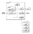
- FIG. 1 is a block diagram showing a main configuration of the power supply control device 1 according to the first embodiment.
- the power supply control device 1 is suitably mounted on the vehicle.
- the power supply control device 1 is connected between the battery 2 and the load 3.
- the power supply control device 1 is separately connected to, for example, the power supply line of the battery 2 and one end of the load 3, and the GND line of the battery 2 and the other end of the load 3 are grounded.
- the power supply control device 1 supplies power to and shuts off the load 3 from the battery 2.
- the power supply control device 1 includes a FET (Field Effect Transistor) 10, a 5V power supply circuit 11, an input circuit 12, a microcomputer (hereinafter referred to as a microcomputer) 13, and a connector 14.
- the connector 14 is provided with a plurality of connection ports 15. Each connection port 15 is provided corresponding to the current value flowing through the load (for example, 12A, 20A, 24A, etc.).
- the 5V power supply circuit 11 and the input circuit 12 are connected to the microcomputer 13. Further, the microcomputer 13 is connected to each FET 10. Further, the FET 10 is connected to the connector 14, and the load 3 is connected to each connection port 15. Further, the power supply control device 1 has a first communication unit 16, and the microcomputer 13 can acquire specification information of the load 3 connected to the connector 14 via the first communication unit 16. Further, the microcomputer 13 can communicate with the diagnostic tool 6 connected from the outside.
- the FET 10 is, for example, an N-channel type FET, the gate terminal of the FET 10 is connected to the microcomputer 13, and the source terminal of the FET 10 is connected to the connector 14.
- the FET10 drain terminal is connected to the power line of the battery 2. The illustration of each terminal of the FET is omitted.
- the FET 10 when the voltage value of the gate based on the potential of the source is equal to or higher than a constant voltage value, a current can flow through the drain and the source. At this time, the FET 10 is on. Further, in the FET 10, when the voltage value of the gate based on the potential of the source is less than a constant voltage value, no current flows through the drain and the source. At this time, the FET 10 is off.
- the 5V power supply circuit 11 converts the voltage of the battery 2 into the drive voltage of the microcomputer 13 and supplies it to the microcomputer 13.
- One end of a plurality of switches 4 is connected to the input circuit 12, and the other end of the plurality of switches 4 is grounded.
- Each switch 4 corresponds to a switch of each load 3 such as an air conditioner and a door lock mounted on a vehicle.
- An operation signal instructing the operation of the load 3 and a stop signal instructing the stop of the operation of the load 3 are input to the power supply control device 1 via the input circuit 12 by turning on / off each switch 4.
- the input circuit 12 When the switch 4 is turned off, the input circuit 12 outputs a stop signal instructing the stop of the operation of the load 3 to the microcomputer 13. When the switch 4 is turned on and grounded, the input circuit 12 outputs an operation signal instructing the operation of the load 3 to the microcomputer 13.
- the microcomputer 13 When an operation signal is input, the microcomputer 13 alternately repeats supplying power to the load 3 and shutting it off. As a result, the load 3 is supplied with power, and the load 3 operates.
- the power supply control device 1 shuts off the load 3 when a stop signal is input. As a result, the power supply to the load 3 is stopped, and the load 3 stops the operation.
- switches 4, FETs 10, and connection ports 15 are provided. Although three switches 4, FETs 10 and connection ports 15 are shown in FIG. 1, the number is not limited to three if there are two or more.
- FIG. 2 is a block diagram showing a main configuration of the microcomputer 13.
- the microcomputer 13 includes a control unit 70, a storage unit 71, a first input unit 72, a second input unit 73, an output unit 74, and a second communication unit 75.
- the control unit 70, the storage unit 71, the first input unit 72, the second input unit 73, the output unit 74, and the second communication unit 75 are separately connected to the bus 76.
- the control unit 70 is composed of a CPU (Central Processing Unit), an MPU (Micro Processing Unit), and the like, and controls the operation of the entire power supply control device 1.
- the storage unit 71 includes a ROM (Read Only Memory), a RAM (Random access memory), and the like, and includes a processing program 71a executed by the control unit 70 and a current value or an allowable value of a power value based on the current value. I remember.
- ROM Read Only Memory
- RAM Random access memory
- the operation signal and stop signal of the FET 10 are input to the first input unit 72. Further, the specification information of the load 3 connected to the connection port 15 of the connector 14 is input to the second input unit 73.
- the specification information of the load 3 is the inrush current value of the load 3, the steady current value at the time of driving, the power value, and the like.
- the power value is a value calculated by multiplying the sum of the on-resistances of the FET 10 by (square of the steady current value).
- the output unit 74 is connected to the gate terminal of the FET 10, and the drive signal of the FET 10 is output from the output unit 74.
- the second communication unit 75 communicates with the diagnostic tool 6.
- the diagnostic tool 6 includes a CPU or MPU, a ROM, a RAM, and the like, a control unit 60 that controls the operation of the diagnostic tool 6, a display unit 61 that includes a liquid crystal display that displays an image, and a second communication unit of the microcomputer 13. It has a communication unit 62 that communicates with the 75.
- the control unit 60 displays an image corresponding to the display unit 61 based on the information received from the microcomputer 13 by the communication unit 62.
- the control unit 70 of the microcomputer 13 detects the connection of the load 3 to the connection port 15 based on the communication to the communication unit on the load 3 side.
- the control unit 70 of the microcomputer 13 determines whether or not the load 3 is newly connected to the connection port 15 of the connector 14 based on the differential communication via the communication unit, for example, using CAN (Controller Area Network) or the like. Detect.
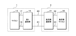
- FIG. 3 is an explanatory diagram illustrating connection of a load to the power supply control device. In the power supply control device 1, the microcomputer 13 is connected to the first communication unit 16 via the transmission line 17 and the reception line 18.
- the load 3 includes, for example, a load-side microcomputer 30 and a load-side communication unit 31 connected to the load-side microcomputer 30 via a transmission line 32 and a reception line 33.
- the load-side microcomputer 30 is configured to include a CPU or MPU, a ROM, a RAM, and the like, and controls the operation of the load 3.
- the first communication unit 16 and the load side communication unit 31 are CAN transceivers, which are connected by two communication lines 80 and 81.
- the control unit 70 of the microcomputer 13 periodically transmits a signal, for example, every 1 msec.
- the load-side microcomputer 30 receives the signal transmitted by the microcomputer 13 via the load-side communication unit 31, the load-side microcomputer 30 transmits a signal to the effect that it has been received to the microcomputer 13.
- the control unit 70 receives the signal transmitted by the load-side microcomputer 30, it detects that the load 3 is newly connected to the connection port 15. As a result, in the power supply control device 1, when a new load 3 is connected to the connection port 15, the connection can be detected.
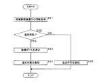
- FIG. 4 is a flowchart showing the procedure of the load addition process performed by the control unit 70.
- the control unit 70 acquires the specification information of the load 3 (S1). The control unit 70 determines whether or not the load 3 can be added based on the specification information of the load 3 (S2). As a result, if the load 3 can be added, it is determined to supply power, and if the load cannot be added, it is determined not to supply power.
- the storage unit 71 stores the permissible value of the total value of the currents flowing through all the loads to be fed by the power supply control device 1 and the permissible value of the power value based on the current value.
- the control unit 70 determines that the load 3 can be added when the total current value or the total power value when a new load 3 is connected is equal to or less than the allowable value.
- the control unit 70 determines that the load 3 cannot be added when the total current value or the total power value when a new load 3 is connected exceeds the allowable value.
- the addable information includes information that identifies the connection port 15 suitable for the connected load 3.
- the control unit 70 determines the connection port 15 corresponding to the current value in the load specification information as the connection port 15 suitable for the load 3.
- the output addable information is transmitted from the second communication unit 75, received by the communication unit 62 by the diagnostic tool 6, and the control unit 60 causes the display unit 61 to display the connection port 15 suitable for connection as an image. Notifies the person connecting the load such as the dealer.
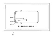
- FIG. 5 is an explanatory diagram showing an example of the notification screen.
- a screen as shown in FIG. 5 is displayed on the display unit 61.
- Image 600 refers to a vehicle on which the load 3 is mounted, and images 601 and 615 of the power supply control device 1 and the connection port 15 are shown in the image 600.
- the image 615 of the connection port 15 suitable for the connected load 3 is shown by hatching.
- the portion corresponding to the connection port 15 may be displayed in a blinking mode or in another mode.
- control unit 70 determines that the load 3 cannot be added (S2: NO)
- the control unit 70 outputs non-addable information (S5) and ends the process.
- the output non-addable information is transmitted from the second communication unit 75, received by the diagnostic tool 6, and displayed on the display unit 61 to notify the person connecting the load such as a dealer to that effect.
- connection port 15 selected by a worker such as a dealer does not correspond to the specification information including the current value and the power value of the load 3.
- the connection port 15 selected by a worker does not correspond to the specification information including the current value and the power value of the load 3.
- the connection to the other connection port 15 corresponding to the newly connected load 3 is urged. be able to.
- the power supply control device 1 is a connection port 15 suitable for the current value in the specification information of the load 3 to be connected, and if there is no connection port 15 to which the load is not connected, even if information indicating that addition is not possible is output. Good.
- the power supply control device 1 is configured to determine whether the load 3 can be added, but other devices may be used, and in the modified example 1, the diagnostic tool 6 is used. Determines whether the load 3 can be added.
- FIG. 6 is a flowchart showing a procedure of load addition processing performed by the control unit 60 of the diagnostic tool 6 according to the modification 1.
- the control unit 60 of the diagnostic tool 6 acquires information including the allowable value of the current and the allowable value of the power value and the specification information of the load 3 from the power supply control device 1 (S21). Based on the acquired information, the control unit 60 determines whether or not the load 3 can be added in the same manner as in the first embodiment (S22).
- control unit 60 determines that the load can be added (S22: YES)
- the control unit 60 determines the connection port 15 suitable for the load 3 in the same manner as in the first embodiment (S23), indicates the position of the connection port 15, and indicates the load 3. Is displayed on the display unit 61 to notify that the addition is possible (S24), and the process ends.
- the display unit 61 is displayed to notify that the addition is not possible (S25), and the process ends.
- the failure of the power supply control device 1 can be prevented and the load 3 can be connected satisfactorily. Further, in the connection of the new load 3 to one connection port 15, if the selected connection port 15 does not correspond to the specification information of the load 3, another load 3 corresponding to the connected load 3 is connected. You can prompt to connect to the connection port.
- FIG. 7 is an explanatory diagram illustrating the connection of the load 3 to the power supply control device 1 according to the second modification.
- the first communication unit 16 and the load side communication unit 31 communicate using single-line communication using a communication protocol of LIN (Local Interconnect Network).
- the first communication unit 16 and the load side communication unit 31 are LIN transceivers, and are connected by a single communication line 82 as shown in FIG. 7.
- the power supply control device 1 and the load 3 transmit and receive signals via the communication line 81, and detect the connection of the load 3 to the connection port 15 as in the first embodiment.
- the communication protocol may be CXPI (Clock Extension Peripheral Interface). Even with the above configuration, when a new load 3 is connected to the connection port 15, the power supply control device 1 can detect the connection.
- connection of the load 3 is detected based on the differential communication, but in the modified example 3, for example, based on the change in the potential detected by the microcomputer 13. Detect.
- FIGS. 8 and 9 are explanatory views for explaining the connection of the load 3 to the power supply control device 1 according to the modification 3.
- FIG. 8 shows a state in which the load 3 is connected to the power supply control device 1
- FIG. 9 shows a state in which the load 3 is not connected.
- the microcomputer 13 includes a detection unit 77.
- the power supply control device 1 has a first resistor R1 and one end of the first resistor R1 is grounded.
- the detection unit 77 is connected to the other end of the first resistor R1.
- the detection unit 77 is, for example, an ADC (Analog to Digital Converter) circuit, periodically detects the potential of the other end of the first resistor R1 (for example, every 1 msec), and inputs the detected value to the control unit 70.
- ADC Analog to Digital Converter
- the resistor R2 is connected between the other end of the first resistor R1 and the battery 2.
- the resistor R2 may be provided in, for example, the power supply control device 1 or the load 3.
- the potential V1 at the other end of the first resistor R1 is the voltage obtained by dividing the voltage supplied from the battery 2 by the ratio of the resistance values of the first resistor R1 and the second resistor R2. It becomes the pressure value.
- the load 3 is not connected, the other end of the first resistor R1 is not connected to the battery 2, and the potential V1 becomes zero volt.
- the potential V1 changes depending on whether the load 3 is connected or not, and the value detected by the detection unit 77 changes.
- the control unit 70 detects the connection of the load 3 by comparing the value detected by the detection unit 77 with the threshold value stored in the storage unit 71, for example.
- the threshold value is set to a value larger than zero volt and smaller than the partial pressure value.
- the threshold value may be set including an error. From the above, for example, if the potential detected by the detection unit 77 is zero volt, the control unit 70 determines that the potential is less than the threshold value, detects that the load 3 is not connected, and detects that the load 3 is not connected, and the other end of the first resistor R1.
- the battery 2 is connected via the second resistor R2 and the partial pressure value is detected, it is determined that the voltage is equal to or higher than the threshold value and it is detected that the load 3 is connected.
- the microcomputer 13 of the power supply control device 1 can detect the connection by detecting the change in the potential V1.
- the power supply control system according to the second embodiment is configured by using a plurality of power supply control devices 1 mounted on the vehicle.
- the same reference numerals are given to the same configurations as those in the first embodiment, and detailed description thereof will be omitted.
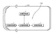
- FIG. 10 is a block diagram showing a main component configuration showing the power supply control system 100 according to the second embodiment.
- the power supply control system 100 is mounted on the vehicle 101 and includes four power supply control devices 1.
- Each power supply control device 1 has the same configuration as that of the first embodiment, and can communicate with each other via the first communication unit 16 or the second communication unit 75.
- FIG. 11 is a flowchart showing a procedure of load addition processing performed by the control unit 70.
- the control unit 70 acquires the specification information of the load 3 (S31). The control unit 70 determines whether or not the load 3 can be added based on the specification information of the load 3 (S32).
- the storage unit 71 stores the permissible value of the total value of the currents flowing through all the loads to which each power supply control device 1 is connected, and the permissible value of the power value based on the current value.
- the control unit 70 determines that the load 3 can be added when the total current value or the total power value when a new load 3 is connected is equal to or less than the allowable value of any of the power supply control devices 1. To do.
- the control unit 70 determines that the load 3 cannot be added when the total current value or the total power value when a new load 3 is connected exceeds the allowable values of all the power supply control devices 1. ..
- the control unit 70 uses the connection port 15 which matches the current value in the load specification information and is not connected to the load 3 as the connection port 15 suitable for the load 3. decide. Information on whether or not the load 3 is connected is acquired by the control unit 70 from another power supply control device 1 via the first communication unit 16 or the second communication unit 75. Note that the power supply control device 1 is a connection port 15 suitable for the current value in the specification information of the load 3 to be connected, and if there is no connection port 15 to which the load is not connected, even if information indicating that addition is not possible is output. Good.
- the control unit 70 determines from the power supply control device 1 a power supply control device having a connection port 15 corresponding to the connected load 3 (S32: YES). S33), the addable information is output (S34), and the process ends.
- the control unit 70 determines that the load 3 cannot be added (S32: NO)
- the control unit 70 outputs non-addable information (S35) and ends the process.
- the addable information includes information indicating the determined power supply control device 1 and the connection port 15 suitable for the connected load 3. It should be noted that the mode may be such that only one of the power supply control device 1 and the connection port 15 is notified.
- FIG. 12 is an explanatory diagram showing an example of the notification screen. For example, a screen as shown in FIG. 12 is displayed on the display unit 61.
- the image 600 refers to a vehicle on which the load 3 is mounted, and the images 601 and 615 of the power supply control device 1 and the connection port 15 are shown in the image 600.
- the image 615 of the connection port 15 suitable for the connected load 3 and the image of the power supply control device 1 are shown by hatching.
- the portion corresponding to the power supply control device 1 and the connection port 15 may be displayed in a blinking mode or in another mode.
- the "box" in the message part of this image refers to the power supply control device.
- connection port 15 In the connection of a new load 3 to one connection port 15, if the connection port selected for the load 3 does not correspond based on the specification information of the load 3, another connection corresponding to the load 3 is supported. It is possible to prompt the connection to the port 15 or the power supply control device 1. As a result, it is possible to prevent the power supply control device 1 from failing and to connect the load satisfactorily. Further, it is possible to determine whether or not the load connected to the selected connection port is compatible based on the current value or the power value to the load, and to connect the load satisfactorily.
- Power supply control device 11 5V power supply circuit 12 Input circuit 14 Connector 15 Connection port 16 1st communication unit 17 Transmission line 18 Reception line 2 Battery (power supply) 3 Load 30 Load-side microcomputer 31 Load-side communication unit 32 Transmission line 33 Reception line 4 Switch 6 Diag tool 60 Control unit 61 Display unit 62 Communication unit 13 Microcomputer 70 Control unit (acquisition unit, determination unit, detection unit) 71 Storage unit 71a Processing program 72 1st input unit 73 2nd input unit 74 Output unit 75 2nd communication unit 76 Bus 77 Detection unit 80, 81 Communication line 82 Communication line 100 Power supply control system 101 Vehicle 600,601,615 Image R1 1st resistor R2 2nd resistor
Landscapes
- Engineering & Computer Science (AREA)
- Power Engineering (AREA)
- Direct Current Feeding And Distribution (AREA)
Abstract
給電制御装置は、電源から負荷への給電を制御する給電制御装置であって、前記負荷が接続される複数の接続ポートと、一の前記接続ポートに前記負荷が接続された場合、前記負荷の仕様情報を取得する取得部と、該取得部が取得した仕様情報に基づいて前記負荷に給電を行うか否かを決定する決定部と、該決定部が前記負荷に給電を行わないと決定した場合、前記負荷に給電を行わないことを示す情報を出力する出力部とを備える。
Description
本開示は、給電制御装置、給電制御システム及び給電制御方法に関する。
本出願は、2019年3月12日出願の日本出願第2019-045074号に基づく優先権を主張し、前記日本出願に記載された全ての記載内容を援用するものである。
本出願は、2019年3月12日出願の日本出願第2019-045074号に基づく優先権を主張し、前記日本出願に記載された全ての記載内容を援用するものである。
特許文献1には、車両における電源及び負荷の間に配され、電源から負荷への給電を制御する給電制御装置が開示されている。給電制御装置はFET(Field Effect Transistor)等のスイッチング素子を有し、該スイッチング素子のオンオフにより、給電の制御を行う。また、給電制御装置は、負荷が接続されるコネクタを備える。コネクタは、負荷に供給する電流値等に対応する複数の接続ポートを含む場合がある。
本開示の一態様に係る給電制御装置は、電源から負荷への給電を制御する給電制御装置であって、前記負荷が接続される複数の接続ポートと、一の前記接続ポートに前記負荷が接続された場合、前記負荷の仕様情報を取得する取得部と、該取得部が取得した仕様情報に基づいて前記負荷に給電を行うか否かを決定する決定部と、該決定部が前記負荷に給電を行わないと決定した場合、前記負荷に給電を行わないことを示す情報を出力する出力部とを備える。
本開示の一態様に係る給電制御システムは、電源から負荷への給電を制御する複数の給電制御装置を備え、各給電制御装置は、前記負荷が接続され、前記負荷の仕様情報に対応する複数の接続ポートを有し、一の前記給電制御装置は、該一の給電制御装置の前記接続ポートに前記負荷が接続された場合、前記負荷の仕様情報に係る情報を取得する取得部と、該取得部が取得した情報に基づいて前記負荷に給電を行うか否かを決定する決定部と、該決定部が前記負荷に給電を行うと決定した場合、前記負荷の仕様情報に対応する前記接続ポート、又は前記給電制御装置を示す情報を出力する出力部とを有する。
本開示の一態様に係る給電制御方法は、電源から負荷への給電を制御する給電制御方法であって、前記負荷が接続され、前記負荷の仕様情報に対応する複数の接続ポートを有する給電制御装置の前記接続ポートに前記負荷が接続された場合に前記負荷の仕様情報に係る情報を取得し、取得した情報に基づいて前記負荷に給電を行うか否かを決定し、前記負荷に給電を行うと決定した場合、前記負荷の仕様情報に対応する前記接続ポート、又は前記給電制御装置を示す情報を出力する。
なお本願は、このような特徴的な各構成部を備えた各装置を含む給電制御装置として実現することができるだけでなく、かかる特徴的なステップを含む制御プログラムとして実現することができる。また、給電制御装置の構成部の一部又は全部を実現する半導体集積回路として実現したり、給電制御装置を用いた制御システム、及びその他のシステムとして実現したりすることができる。
[本開示が解決しようとする課題]
新しい負荷の給電制御装置への接続において、該負荷を対応していない接続ポートに誤って接続することにより、故障の原因となる虞がある。
新しい負荷の給電制御装置への接続において、該負荷を対応していない接続ポートに誤って接続することにより、故障の原因となる虞がある。
本開示の目的は、良好に負荷を接続することができる給電制御装置、給電制御システム及び給電制御方法を提供することにある。
[本開示の効果]
上記によれば、良好に負荷を接続することができる。
上記によれば、良好に負荷を接続することができる。
[本開示の実施形態の説明]
最初に本開示の実施態様を列記して説明する。また、以下に記載する実施形態の少なくとも一部を任意に組み合わせても良い。
最初に本開示の実施態様を列記して説明する。また、以下に記載する実施形態の少なくとも一部を任意に組み合わせても良い。
本開示の一態様に係る給電制御装置は、電源から負荷への給電を制御する給電制御装置であって、前記負荷が接続される複数の接続ポートと、一の前記接続ポートに前記負荷が接続された場合、前記負荷の仕様情報を取得する取得部と、該取得部が取得した仕様情報に基づいて前記負荷に給電を行うか否かを決定する決定部と、該決定部が前記負荷に給電を行わないと決定した場合、前記負荷に給電を行わないことを示す情報を出力する出力部とを備える。
本態様にあっては、一の接続ポートへの新たな負荷の接続において、選択された接続ポートが負荷の仕様情報に対応していない場合に、負荷に給電を行わないことを示す情報を出力することにより、対応していない状態のまま、負荷に給電が行われることを防止することができる。これにより、良好に負荷を接続することができる。
本開示の一態様に係る給電制御装置は、各接続ポートは前記負荷の仕様情報に対応しており、前記出力部は前記決定部が前記負荷に給電を行うと決定した場合、前記負荷の仕様情報に対応する前記接続ポートを示す情報を出力する。
本態様にあっては、一の接続ポートへの新たな負荷の接続において、選択された接続ポートが負荷の仕様情報に対応していない場合に、負荷に対応した他の接続ポートへの接続を促すことができる。
本開示の一態様に係る給電制御装置は、前記負荷の仕様情報は前記負荷への給電における電流値である。
本態様にあっては、負荷への電流値に基づいて、選択された接続ポートに接続される負荷が対応しているか否かを判断することができる。
本開示の一態様に係る給電制御装置は、前記負荷の仕様情報は前記負荷への給電における電流値に基づく電力値である。
本態様にあっては、負荷への電力供給における電力値に基づいて、選択された接続ポートに接続される負荷が対応しているか否かを判断することができる。
本開示の一態様に係る給電制御システムは、電源から負荷への給電を制御する複数の給電制御装置を備え、各給電制御装置は、前記負荷が接続され、前記負荷の仕様情報に対応する複数の接続ポートを有し、一の前記給電制御装置は、該一の給電制御装置の前記接続ポートに前記負荷が接続された場合、前記負荷の仕様情報に係る情報を取得する取得部と、該取得部が取得した情報に基づいて前記負荷に給電を行うか否かを決定する決定部と、該決定部が前記負荷に給電を行うと決定した場合、前記負荷の仕様情報に対応する前記接続ポート、又は前記給電制御装置を示す情報を出力する出力部とを有する。
本開示の一態様に係る給電制御方法は、電源から負荷への給電を制御する給電制御方法であって、前記負荷が接続され、前記負荷の仕様情報に対応する複数の接続ポートを有する給電制御装置の前記接続ポートに前記負荷が接続された場合に前記負荷の仕様情報に係る情報を取得し、取得した情報に基づいて前記負荷に給電を行うか否かを決定し、前記負荷に給電を行うと決定した場合、前記負荷の仕様情報に対応する前記接続ポート、又は前記給電制御装置を示す情報を出力する。
本態様にあっては、一の接続ポートへの新たな負荷の接続において、選択された接続ポートが負荷の仕様情報に対応していない場合に、負荷に対応している他の接続ポート又は給電制御装置への接続を促すことができる。これにより、良好に負荷を接続することができる。
本開示の一態様に係る給電制御装置は、前記負荷の前記接続ポートへの接続を、前記負荷側に対する通信に基づいて検知する検知部を備える。
本開示の一態様に係る給電制御システムは、各給電制御装置は、前記負荷の前記接続ポートへの接続を、前記負荷側に対する通信に基づいて検知する検知部を備える。
本態様にあっては、新たな負荷が接続ポートに接続された場合にその接続を検知できる。
本開示の一態様に係る給電制御装置は、前記負荷の前記接続ポートへの接続を検知する検知部と、該検知部に一端が接続され、他端が接地されている第1抵抗とを備え、前記負荷が接続された場合において、前記第1抵抗の一端及び前記電源の間に第2抵抗が接続され、前記検知部は、前記負荷の接続に伴う前記抵抗器の一端の電位の変化に基づいて検知する。
本開示の一態様に係る給電制御システムは、各給電制御装置は、前記負荷の前記接続ポートへの接続を検知する検知部と、一端が接地されている第1抵抗とを備え、前記負荷が接続された場合において、前記第1抵抗の他端及び前記電源の間に第2抵抗が接続され、前記検知部は、前記負荷の接続に伴う前記第1抵抗の他端の電位の変化に基づいて検知する。
本態様にあっては、新たな負荷が接続ポートに接続された場合にその接続を検知できる。
本開示の一態様に係る給電制御システムは、前記負荷の仕様情報は前記負荷への給電における電流値であり、各給電制御装置は、各接続ポートに接続される前記負荷の前記電流値の合計値の許容値が設定されており、前記決定部は、新たに接続される負荷に給電を行うか否かを負荷の仕様情報及び前記許容値に基づいて決定し、前記出力部は、新たな負荷が接続された場合に前記合計値が前記許容値を超過しない前記接続ポート又は給電制御装置を示す情報を出力する。
本態様にあっては、負荷への電流値に基づいて、選択された接続ポートに接続される負荷が対応しているか否かを判断し、良好に負荷を接続することができる。
[本開示の実施形態の詳細]
以下、本開示をその実施の形態を示す図面に基づいて具体的に説明する。なお、本開示はこれらの例示に限定されるものではなく、請求の範囲によって示され、請求の範囲と均等の意味及び範囲内でのすべての変更が含まれることが意図される。
以下、本開示をその実施の形態を示す図面に基づいて具体的に説明する。なお、本開示はこれらの例示に限定されるものではなく、請求の範囲によって示され、請求の範囲と均等の意味及び範囲内でのすべての変更が含まれることが意図される。
(実施の形態1)
図1は、実施の形態1における給電制御装置1の要部構成を示すブロック図である。給電制御装置1は、車両に好適に搭載されている。給電制御装置1は、バッテリ2及び負荷3間に接続されている。給電制御装置1は、例えばバッテリ2の電源線と、負荷3の一端とに各別に接続されており、バッテリ2のGND線と、負荷3の他端とは接地される。給電制御装置1は、バッテリ2から負荷3への給電と、遮断とを行う。
図1は、実施の形態1における給電制御装置1の要部構成を示すブロック図である。給電制御装置1は、車両に好適に搭載されている。給電制御装置1は、バッテリ2及び負荷3間に接続されている。給電制御装置1は、例えばバッテリ2の電源線と、負荷3の一端とに各別に接続されており、バッテリ2のGND線と、負荷3の他端とは接地される。給電制御装置1は、バッテリ2から負荷3への給電と、遮断とを行う。
給電制御装置1は、FET(Field Effect Transistor)10、5V電源回路11、入力回路12、マイクロコンピュータ(以下、マイコンという)13及びコネクタ14を有する。コネクタ14には複数の接続ポート15が設けられている。各接続ポート15は、負荷に流れる電流値(例えば、12A、20A、24A等)に対応させて設けられている。
5V電源回路11及び入力回路12は、マイコン13に接続されている。また、マイコン13は、各FET10に接続されている。また、FET10はコネクタ14に接続されており、各接続ポート15に負荷3が接続される。更に、給電制御装置1は第1通信部16を有し、マイコン13は、第1通信部16を介して、コネクタ14に接続された負荷3の仕様情報を取得可能である。また、マイコン13は、外部から接続されるダイアグツール6と相互通信可能である。
FET10は、例えばNチャネル型のFETであり、FET10のゲート端子がマイコン13に接続され、FET10のソース端子がコネクタ14に接続される。FET10ドレイン端子は、バッテリ2の電源線に接続される。なお、FETの各端子の図示は省略している。
FET10において、ソースの電位を基準としたゲートの電圧値が一定電圧値以上である場合、ドレイン及びソースを介して電流が流れることが可能である。このとき、FET10はオンである。
また、FET10において、ソースの電位を基準としたゲートの電圧値が一定電圧値未満である場合、電流がドレイン及びソースを介して流れることない。このとき、FET10はオフである。
また、FET10において、ソースの電位を基準としたゲートの電圧値が一定電圧値未満である場合、電流がドレイン及びソースを介して流れることない。このとき、FET10はオフである。
5V電源回路11は、バッテリ2の電圧をマイコン13の駆動電圧に変換してマイコン13に供給する。入力回路12には、複数のスイッチ4の一端が接続されており、複数のスイッチ4の他端は接地されている。各スイッチ4は、車両に搭載されるエアコン、ドアロック等の各負荷3のスイッチに対応している。給電制御装置1には、各スイッチ4のオンオフにより入力回路12を介して、負荷3の作動を指示する作動信号と、負荷3の動作の停止を指示する停止信号とが入力される。
入力回路12は、スイッチ4をオフした場合、負荷3の動作の停止を指示する停止信号をマイコン13に出力する。入力回路12は、スイッチ4をオンして接地した場合、負荷3の作動を指示する作動信号をマイコン13に出力する。
マイコン13は、作動信号が入力された場合、負荷3への給電と、遮断とを交互に繰り返す。これにより、負荷3に給電され、負荷3は作動する。給電制御装置1は、停止信号が入力された場合、負荷3を遮断する。これにより、負荷3への給電が停止し、負荷3は動作を停止する。
FET10がオンに切替わった場合、電流がバッテリ2の正極からFET10を介して電流が流れ、バッテリ2から負荷3へ給電される。FET10がオフに切替わった場合、電流が負荷3に流れず、負荷3への給電が停止する。
スイッチ4、FET10、接続ポート15は、同数個(図1では3つ)設けられている。なお、スイッチ4、FET10、接続ポート15は図1においては3個ずつ示されているが、2個以上であれば3個に限られない。
図2はマイコン13の要部構成を示すブロック図である。マイコン13は、制御部70、記憶部71、第1入力部72、第2入力部73、出力部74、第2通信部75を有する。
制御部70、記憶部71、第1入力部72、第2入力部73、出力部74、第2通信部75は、バス76に各別に接続されている。制御部70は、CPU(Central Processing Unit)、MPU(Micro Processing Unit)等により構成され、給電制御装置1全体の動作を制御する。
記憶部71は、ROM(Read Only Memory)、RAM(Random access memory)等を含んで構成され、制御部70が実行する処理プログラム71aと、電流値又は該電流値に基づく電力値の許容値等を記憶している。
第1入力部72には、FET10の作動信号及び停止信号が入力される。また、第2入力部73には、コネクタ14の接続ポート15に接続された負荷3の仕様情報が入力される。負荷3の仕様情報は、負荷3の突入電流値、駆動時の定常電流値及び電力値等である。電力値は、FET10のオン抵抗の和×(定常電流値の2乗)で算出される値である。
出力部74は、FET10のゲート端子に接続され、出力部74からFET10の駆動信号が出力される。第2通信部75は、ダイアグツール6と相互通信を行う。
ダイアグツール6は、CPU又はMPU、及びROM、RAM等を含み、ダイアグツール6の動作を制御する制御部60と、画像を表示する液晶ディスプレイを含む表示部61と、マイコン13の第2通信部75と相互に通信する通信部62を有する。ダイアグツール6においては、通信部62によりマイコン13から受信した情報に基づいて、制御部60が表示部61に対応する画像を表示させる。
マイコン13の制御部70は、負荷3の接続ポート15への接続を、負荷3側の通信部に対する通信に基づいて検出する。マイコン13の制御部70は、コネクタ14の接続ポート15に新たに負荷3が接続されたか否かを、通信部を介した、例えばCAN(Controller Area Network)等を用いた差動通信に基づいて検知する。図3は、給電制御装置への負荷の接続を説明する説明図である。給電制御装置1において、マイコン13は送信線17及び受信線18を介して第1通信部16に接続されている。
ここで、負荷3は、例えば、負荷側マイコン30と、該負荷側マイコン30に送信線32及び受信線33を介して接続されている負荷側通信部31とを備える。負荷側マイコン30は、CPU又はMPU、及びROM、RAM等を含んで構成され、負荷3の動作を制御する。
第1通信部16及び負荷側通信部31はCANトランシーバであり、2本の通信線80,81により接続されている。マイコン13の制御部70は定期的に例えば1msecごとに信号を送信する。マイコン13が送信した信号を、負荷側通信部31を介して負荷側マイコン30が受信した場合、負荷側マイコン30は受信した旨の信号をマイコン13側に送信する。制御部70は、負荷側マイコン30が送信した信号を受信した場合、接続ポート15に新たに負荷3が接続されたことを検知する。これにより、給電制御装置1において、新たな負荷3が接続ポート15に接続された場合に、その接続を検知できる。
制御部70は、コネクタ14の接続ポート15への新たな負荷3の接続を検知した場合、以下の負荷追加処理を行う。図4は、制御部70が行う負荷追加処理の手順を示すフローチャートである。
制御部70は、負荷3の仕様情報を取得する(S1)。制御部70は、負荷3の仕様情報に基づいて、該負荷3が追加可能であるか否かを判定する(S2)。これにより、負荷3が追加可能である場合は、給電を行うことが決定され、負荷が追加できない場合は、給電を行わないことが決定される。
具体的には、次のように負荷3が追加可能であるか否かを決定する。記憶部71は、給電制御装置1により給電を行う全ての負荷に流れる電流の合計値の許容値と、該電流値に基づく電力値の許容値を記憶している。制御部70は、新たな負荷3が接続された場合の電流値の合計又は電力値の合計が前記許容値以下である場合に負荷3が追加可能であると決定する。制御部70は、新たな負荷3が接続された場合の電流値の合計又は電力値の合計が前記許容値を超過する場合に負荷3は追加不可であると決定する。
制御部70は、負荷3が追加可能であると判定した場合(S2:YES)、接続された負荷3に適する接続ポート15を決定し(S3)、追加可能情報を出力して(S4)、処理を終了する。追加可能情報には、接続された負荷3に適する接続ポート15を識別する情報が含まれている。
制御部70は、負荷の仕様情報における電流値に対応する接続ポート15を負荷3に適する接続ポート15として決定する。
出力された追加可能情報は、第2通信部75から送信され、ダイアグツール6が通信部62にて受信し、制御部60が表示部61に接続に適した接続ポート15を画像で表示させることにより、ディーラー等負荷を接続する者に通知される。
図5は、通知画面の一例を示す説明図である。表示部61には、例えば、図5に示すような画面が表示される。画像600は、負荷3が搭載される車両を指し、画像600の中に、給電制御装置1及び接続ポート15の画像601,615が示されている。このとき、接続された負荷3に適する接続ポート15の画像615がハッチングで示されている。なお、該接続ポート15に対応する箇所が点滅する態様又はその他の態様で表示してもよい。
制御部70は、負荷3が追加可能でないと判定した場合(S2:NO)、追加不可情報を出力して(S5)処理を終了する。出力された追加不可情報は、第2通信部75から送信され、ダイアグツール6が受信し、表示部61に表示されることにより、ディーラー等負荷を接続する者にその旨が通知される。
一の接続ポート15への新たな負荷3の接続において、負荷3の電流値及び電力値を含む仕様情報に対して、ディーラー等の作業者に選択された接続ポート15が対応していない場合に、負荷3に給電を行わないことを示す情報を出力することにより、対応していない状態のまま、負荷3に給電が行われることを防止することができる。これにより、給電制御装置1の故障を防止し、良好に負荷3を接続することができる。また、一の接続ポート15への新たな負荷3の接続において、負荷3の仕様情報に対応していない場合に、新たに接続される負荷3に対応した他の接続ポート15への接続を促すことができる。更に、上記の構成においては、負荷への電流値、負荷への電力供給における電力値に基づいて、選択された接続ポートに、接続される負荷が対応しているか否かを判断することができる。
なお、給電制御装置1は接続する負荷3の仕様情報における電流値に適する接続ポート15であって、負荷が未接続の接続ポート15がない場合、追加不可である旨の情報を出力してもよい。
(変形例1)
また実施の形態1に係る給電制御装置1においては、負荷3の追加可能の決定を給電制御装置1が行う構成としたが、他の装置が行ってもよく、変形例1においてはダイアグツール6が負荷3の追加可能の決定を行う。
また実施の形態1に係る給電制御装置1においては、負荷3の追加可能の決定を給電制御装置1が行う構成としたが、他の装置が行ってもよく、変形例1においてはダイアグツール6が負荷3の追加可能の決定を行う。
図6は、変形例1に係るダイアグツール6の制御部60が行う負荷追加処理の手順を示すフローチャートである。ダイアグツール6の制御部60は、給電制御装置1から、電流の許容値及び電力値の許容値と、負荷3の仕様情報とを含む情報を取得する(S21)。制御部60は、取得した情報に基づいて、負荷3を追加可能であるか否かを実施の形態1と同様に判定する(S22)。
制御部60は追加可能であると判定した場合(S22:YES)、負荷3に適した接続ポート15を実施の形態1と同様に決定し(S23)、接続ポート15の位置を示し、負荷3を追加可能である旨を表示部61に表示させて通知し(S24)、処理を終了する。制御部60は追加可能でないと判定した場合(S22:NO)、追加不可である旨を表示部61に表示させて通知し(S25)、処理を終了する。
本変形例1においても、給電制御装置1の故障を防止し、良好に負荷3を接続することができる。また、一の接続ポート15への新たな負荷3の接続において、負荷3の仕様情報に対して、選択された接続ポート15が対応していない場合に、接続される負荷3に対応する他の接続ポートへの接続を促すことができる。
(変形例2)
また実施の形態1に係る給電制御装置1においては、差動通信に基づいて負荷3の接続を検知する態様としたが、変形例2においてはいわゆる単線通信に基づいて検知する。図7は、変形例2に係る給電制御装置1への負荷3の接続を説明する説明図である。第1通信部16及び負荷側通信部31は通信プロトコルをLIN(Local Interconnect Network)として、通信が単線通信により行われる。第1通信部16及び負荷側通信部31はLINトランシーバであり、図7に示すように単一の通信線82により接続されている。給電制御装置1及び負荷3は、通信線81を介して信号の送受信を行い、実施の形態1と同様に、接続ポート15への負荷3の接続を検知する。なお、通信プロトコルをCXPI(Clock Extension Peripheral Interface)としてもよい。以上の構成によっても、新たな負荷3が接続ポート15に接続された場合に、給電制御装置1が接続の検知を行うことができる。
また実施の形態1に係る給電制御装置1においては、差動通信に基づいて負荷3の接続を検知する態様としたが、変形例2においてはいわゆる単線通信に基づいて検知する。図7は、変形例2に係る給電制御装置1への負荷3の接続を説明する説明図である。第1通信部16及び負荷側通信部31は通信プロトコルをLIN(Local Interconnect Network)として、通信が単線通信により行われる。第1通信部16及び負荷側通信部31はLINトランシーバであり、図7に示すように単一の通信線82により接続されている。給電制御装置1及び負荷3は、通信線81を介して信号の送受信を行い、実施の形態1と同様に、接続ポート15への負荷3の接続を検知する。なお、通信プロトコルをCXPI(Clock Extension Peripheral Interface)としてもよい。以上の構成によっても、新たな負荷3が接続ポート15に接続された場合に、給電制御装置1が接続の検知を行うことができる。
(変形例3)
また本実施の形態に係る給電制御装置1においては、差動通信に基づいて負荷3の接続を検知する態様としたが、変形例3においては、例えばマイコン13が検出する電位の変化に基づいて検知する。
また本実施の形態に係る給電制御装置1においては、差動通信に基づいて負荷3の接続を検知する態様としたが、変形例3においては、例えばマイコン13が検出する電位の変化に基づいて検知する。
図8及び図9は、変形例3に係る給電制御装置1への負荷3の接続を説明する説明図である。図8は負荷3が給電制御装置1に接続された状態を示し、図9は負荷3が接続されていない状態を示す。図8及び図9に示すように、マイコン13は検出部77を備える。また、給電制御装置1は第1抵抗R1を有し、第1抵抗R1の一端は接地されている。検出部77は、第1抵抗R1の他端に接続されている。
検出部77は、例えばADC(Analog to Digital Converter )回路であり、第1抵抗R1の他端の電位を定期的に(例えば1msecごとに)検出し、検出した値を制御部70に入力する。なお、図8及び図9においては、マイコン13の制御部70及び検出部77以外の構成部の図示は省略しており、また、コネクタ14等の図示は省略している。
ここで、負荷3が給電制御装置1に接続された場合、図8に示すように、第1抵抗R1の他端及びバッテリ2の間に抵抗R2が接続される。抵抗R2は例えば、給電制御装置1に設けられていてもよく、また、負荷3に設けられていてもよい。図8に示す回路においては、第1抵抗R1の他端の電位V1は、バッテリ2から供給される電圧を第1抵抗R1及び第2抵抗R2の抵抗値の大きさの比により分圧した分圧値となる。負荷3が接続されていない場合、第1抵抗R1の他端はバッテリ2に接続されておらず、電位V1はゼロボルトとなる。
したがって、負荷3が接続された場合と接続されていない場合とにおいて電位V1が変化し、検出部77が検出する値が変化する。負荷が接続されていない場合、制御部70は、検出部77が検出する値と、例えば記憶部71に記憶されている閾値とを比較することにより、負荷3の接続を検知する。ここで、閾値はゼロボルトよりも大きく、前記分圧値よりも小さい値に設定される。なお、閾値は誤差を含めて設定することとしてもよい。
以上より、例えば、制御部70は、検出部77が検出した電位がゼロボルトであれば、閾値未満であると判定して負荷3が接続されていないことを検知し、第1抵抗R1の他端に第2抵抗R2を介してバッテリ2が接続されて前記分圧値を検出した場合、閾値以上であると判定して負荷3が接続されたこと検知する。
以上より、例えば、制御部70は、検出部77が検出した電位がゼロボルトであれば、閾値未満であると判定して負荷3が接続されていないことを検知し、第1抵抗R1の他端に第2抵抗R2を介してバッテリ2が接続されて前記分圧値を検出した場合、閾値以上であると判定して負荷3が接続されたこと検知する。
以上のように、新たな負荷3が接続ポート15に接続された場合、給電制御装置1のマイコン13は、電位V1の変化を検出することにより、その接続の検知を行うことができる。
(実施の形態2)
実施の形態2における給電制御システムは、車両に搭載される複数の給電制御装置1を用いて構成されている。実施形態2における給電制御システムの構成について実施の形態1と同様の構成については同一の符号を付して詳細な説明を省略する。
実施の形態2における給電制御システムは、車両に搭載される複数の給電制御装置1を用いて構成されている。実施形態2における給電制御システムの構成について実施の形態1と同様の構成については同一の符号を付して詳細な説明を省略する。
図10は、実施の形態2に係る給電制御システム100を示す要部構成を示すブロック図である。図10に示すように、給電制御システム100は車両101に搭載されており、4つの給電制御装置1を備える。各給電制御装置1は、実施の形態1と同様の構成をなし、第1通信部16又は第2通信部75を介して相互に通信可能である。
いずれかの給電制御装置1の接続ポート15への負荷3の接続が検知された場合に、該接続ポート15を有する給電制御装置1において、マイコン13の制御部70は下記の負荷追加処理を行う。なお、負荷3の接続ポート15への接続は、上述の差動通信、単線通信又は電位変化の検出に基づいて行われる。図11は、制御部70が行う負荷追加処理の手順を示すフローチャートである。
制御部70は、負荷3の仕様情報を取得する(S31)。制御部70は、負荷3の仕様情報に基づいて、該負荷3が追加可能であるか否かを判定する(S32)。
具体的には、次のように負荷3が追加可能であるか否かを決定する。記憶部71は、各給電制御装置1が接続された全ての負荷に流れる電流の合計値の許容値と、該電流値に基づく電力値の許容値を記憶している。制御部70は、新たな負荷3が接続された場合の電流値の合計又は電力値の合計が、いずれかの給電制御装置1の許容値以下である場合に負荷3が追加可能であると決定する。制御部70は、新たな負荷3が接続された場合の電流値の合計又は電力値の合計が全ての各給電制御装置1の許容値を超過する場合に負荷3は追加不可であると決定する。
制御部70は、負荷3を追加可能である給電制御装置1の内、負荷の仕様情報における電流値に一致し、且つ負荷3が接続されていない接続ポート15を負荷3に適する接続ポート15として決定する。負荷3が接続されているか否かの情報は、制御部70が第1通信部16又は第2通信部75を介して他の給電制御装置1から取得する。なお、給電制御装置1は接続する負荷3の仕様情報における電流値に適する接続ポート15であって、負荷が未接続の接続ポート15がない場合、追加不可である旨の情報を出力してもよい。
制御部70は、負荷3が追加可能であると判定した場合(S32:YES)、接続された負荷3に対応する接続ポート15を有する給電制御装置を、給電制御装置1の内から決定し(S33)、追加可能情報を出力して(S34)、処理を終了する。制御部70は、負荷3が追加可能でないと判定した場合(S32:NO)、追加不可情報を出力して(S35)処理を終了する。追加可能情報には、決定した給電制御装置1と、接続された負荷3に適する接続ポート15とを示す情報が含まれている。なお、給電制御装置1又は接続ポート15のいずれかのみを通知する態様であってもよい。
出力された追加可能情報は、第2通信部75から送信され、ダイアグツール6が通信部62にて受信し、制御部60が表示部61に対応する接続ポート15を画像で表示させることにより、ディーラー等の負荷を接続する者に通知される。図12は、通知画面の一例を示す説明図である。表示部61には、例えば、図12に示すような画面が表示される。
図12において、画像600は、負荷3が搭載される車両を指し、画像600の中に、給電制御装置1及び接続ポート15の画像601,615が示されている。このとき、接続された負荷3に適する接続ポート15の画像615及び給電制御装置1の画像がハッチングで示されている。なお、給電制御装置1及び接続ポート15に対応する箇所が点滅する態様又はその他の態様で表示してもよい。なお、本画像のメッセージ部分の「ボックス」は給電制御装置を指す。
一の接続ポート15への新たな負荷3の接続において、負荷3の仕様情報に基づいて、負荷3に選択された接続ポートが対応していない場合に、負荷3に対応している他の接続ポート15又は給電制御装置1への接続を促すことができる。これにより、給電制御装置1の故障を防止し、良好に負荷を接続することができる。また、負荷への電流値又は電力値に基づいて、選択された接続ポートに接続される負荷が対応しているか否かを判断し、良好に負荷を接続することができる。
今回開示された実施形態はすべての点で例示であって、制限的なものではないと考えられるべきである。本発明の範囲は、上記した意味では無く、請求の範囲によって示され、請求の範囲と均等の意味及び範囲内でのすべての変更が含まれることが意図される。
1 給電制御装置
11 5V電源回路
12 入力回路
14 コネクタ
15 接続ポート
16 第1通信部
17 送信線
18 受信線
2 バッテリ(電源)
3 負荷
30 負荷側マイコン
31 負荷側通信部
32 送信線
33 受信線
4 スイッチ
6 ダイアグツール
60 制御部
61 表示部
62 通信部
13 マイコン
70 制御部(取得部、決定部、検知部)
71 記憶部
71a 処理プログラム
72 第1入力部
73 第2入力部
74 出力部
75 第2通信部
76 バス
77 検出部
80,81 通信線
82 通信線
100 給電制御システム
101 車両
600,601,615 画像
R1 第1抵抗
R2 第2抵抗
11 5V電源回路
12 入力回路
14 コネクタ
15 接続ポート
16 第1通信部
17 送信線
18 受信線
2 バッテリ(電源)
3 負荷
30 負荷側マイコン
31 負荷側通信部
32 送信線
33 受信線
4 スイッチ
6 ダイアグツール
60 制御部
61 表示部
62 通信部
13 マイコン
70 制御部(取得部、決定部、検知部)
71 記憶部
71a 処理プログラム
72 第1入力部
73 第2入力部
74 出力部
75 第2通信部
76 バス
77 検出部
80,81 通信線
82 通信線
100 給電制御システム
101 車両
600,601,615 画像
R1 第1抵抗
R2 第2抵抗
Claims (11)
- 電源から負荷への給電を制御する給電制御装置であって、
前記負荷が接続される複数の接続ポートと、
一の前記接続ポートに前記負荷が接続された場合、前記負荷の仕様情報を取得する取得部と、
該取得部が取得した仕様情報に基づいて前記負荷に給電を行うか否かを決定する決定部と、
該決定部が前記負荷に給電を行わないと決定した場合、前記負荷に給電を行わないことを示す情報を出力する出力部と
を備える給電制御装置。 - 各接続ポートは前記負荷の仕様情報に対応しており、
前記出力部は前記決定部が前記負荷に給電を行うと決定した場合、前記負荷の仕様情報に対応する前記接続ポートを示す情報を出力する請求項1に記載の給電制御装置。 - 前記負荷の仕様情報は前記負荷への給電における電流値である請求項1又は請求項2に記載の給電制御装置。
- 前記負荷の仕様情報は前記負荷への給電における電流値に基づく電力値である請求項1又は請求項2に記載の給電制御装置。
- 前記負荷の前記接続ポートへの接続を、前記負荷側に対する通信に基づいて検知する検知部を備える
請求項1から請求項4までのいずれか一つに記載の給電制御装置。 - 前記負荷の前記接続ポートへの接続を検知する検知部と、
一端が接地されている第1抵抗と
を備え、
前記負荷が接続された場合において、前記第1抵抗の他端及び前記電源の間に第2抵抗が接続され、
前記検知部は、前記負荷の接続に伴う前記第1抵抗の他端の電位の変化に基づいて検知する
請求項1から請求項4までのいずれか一つに記載の給電制御装置。 - 電源から負荷への給電を制御する複数の給電制御装置を備え、
各給電制御装置は、前記負荷が接続され、前記負荷の仕様情報に対応する複数の接続ポートを有し、
一の前記給電制御装置は、
該一の給電制御装置の前記接続ポートに前記負荷が接続された場合、前記負荷の仕様情報に係る情報を取得する取得部と、
該取得部が取得した情報に基づいて前記負荷に給電を行うか否かを決定する決定部と、
該決定部が前記負荷に給電を行うと決定した場合、前記負荷の仕様情報に対応する前記接続ポート、又は前記給電制御装置を示す情報を出力する出力部と
を有する給電制御システム。 - 前記負荷の仕様情報は前記負荷への給電における電流値であり、
各給電制御装置は、各接続ポートに接続される前記負荷の前記電流値の合計値の許容値が設定されており、
前記決定部は、新たに接続される負荷に給電を行うか否かを負荷の仕様情報及び前記許容値に基づいて決定し、
前記出力部は、新たな負荷が接続された場合に前記合計値が前記許容値を超過しない前記接続ポート又は給電制御装置を示す情報を出力する
請求項7に記載の給電制御システム。 - 各給電制御装置は、前記負荷の前記接続ポートへの接続を、前記負荷側に対する通信に基づいて検知する検知部を備える請求項7又は請求項8に記載の給電制御システム。
- 各給電制御装置は、
前記負荷の前記接続ポートへの接続を検知する検知部と、
一端が接地されている第1抵抗と
を備え、
前記負荷が接続された場合において、前記第1抵抗の他端及び前記電源の間に第2抵抗が接続され、
前記検知部は、前記負荷の接続に伴う前記第1抵抗の他端の電位の変化に基づいて検知する
請求項7又は請求項8に記載の給電制御システム。 - 電源から負荷への給電を制御する給電制御方法であって、
前記負荷が接続され、前記負荷の仕様情報に対応する複数の接続ポートを有する給電制御装置の前記接続ポートに前記負荷が接続された場合に前記負荷の仕様情報に係る情報を取得し、
取得した情報に基づいて前記負荷に給電を行うか否かを決定し、
前記負荷に給電を行うと決定した場合、前記負荷の仕様情報に対応する前記接続ポート、又は前記給電制御装置を示す情報を出力する給電制御方法。
Applications Claiming Priority (2)
| Application Number | Priority Date | Filing Date | Title |
|---|---|---|---|
| JP2019-045074 | 2019-03-12 | ||
| JP2019045074A JP2020150634A (ja) | 2019-03-12 | 2019-03-12 | 給電制御装置、給電制御システム及び給電制御方法 |
Publications (1)
| Publication Number | Publication Date |
|---|---|
| WO2020184407A1 true WO2020184407A1 (ja) | 2020-09-17 |
Family
ID=72426220
Family Applications (1)
| Application Number | Title | Priority Date | Filing Date |
|---|---|---|---|
| PCT/JP2020/009567 Ceased WO2020184407A1 (ja) | 2019-03-12 | 2020-03-06 | 給電制御装置、給電制御システム及び給電制御方法 |
Country Status (2)
| Country | Link |
|---|---|
| JP (1) | JP2020150634A (ja) |
| WO (1) | WO2020184407A1 (ja) |
Citations (3)
| Publication number | Priority date | Publication date | Assignee | Title |
|---|---|---|---|---|
| JP4027095B2 (ja) * | 1999-11-22 | 2007-12-26 | シャープ株式会社 | 電力供給システム |
| JP2008158700A (ja) * | 2006-12-21 | 2008-07-10 | Ricoh Co Ltd | 接続検知装置及び接続検知システム |
| JP2015520875A (ja) * | 2012-06-11 | 2015-07-23 | 株式会社デンソー | 接続整合方法及び装置 |
-
2019
- 2019-03-12 JP JP2019045074A patent/JP2020150634A/ja active Pending
-
2020
- 2020-03-06 WO PCT/JP2020/009567 patent/WO2020184407A1/ja not_active Ceased
Patent Citations (3)
| Publication number | Priority date | Publication date | Assignee | Title |
|---|---|---|---|---|
| JP4027095B2 (ja) * | 1999-11-22 | 2007-12-26 | シャープ株式会社 | 電力供給システム |
| JP2008158700A (ja) * | 2006-12-21 | 2008-07-10 | Ricoh Co Ltd | 接続検知装置及び接続検知システム |
| JP2015520875A (ja) * | 2012-06-11 | 2015-07-23 | 株式会社デンソー | 接続整合方法及び装置 |
Also Published As
| Publication number | Publication date |
|---|---|
| JP2020150634A (ja) | 2020-09-17 |
Similar Documents
| Publication | Publication Date | Title |
|---|---|---|
| JP5246504B2 (ja) | 機器及びネットワークシステム | |
| JP3842158B2 (ja) | スイッチ式電源システム用のアクティブ回路保護 | |
| US11863013B2 (en) | Power source selection | |
| CN112771780B (zh) | 车载驱动电路、车载驱动芯片、车载驱动器件及电子设备 | |
| US9577601B2 (en) | Broadcast serial bus termination | |
| JP2020142646A (ja) | 通信故障検出装置 | |
| US20130261928A1 (en) | Operation Support Apparatus, Electronic Device, Electronic Control Unit and Control System | |
| WO2017217289A1 (ja) | 給電制御装置 | |
| US11052764B2 (en) | Power supply device | |
| US12062934B2 (en) | System for distributing electrical energy | |
| JP2020187652A (ja) | 電源電圧監視回路及び制御装置 | |
| US10289590B2 (en) | Electronic device and method of auto switching linking path giving priority to a priority port | |
| WO2020184407A1 (ja) | 給電制御装置、給電制御システム及び給電制御方法 | |
| CN103792458A (zh) | 断开检测装置和方法 | |
| US7701684B2 (en) | Power supply apparatus and power supply system including the same addressing abnormality | |
| US10908664B2 (en) | POE power supply system | |
| US20240275266A1 (en) | Power supply control device and power supply control method | |
| CN111016831A (zh) | 一种车辆能源控制装置 | |
| JP2006345136A (ja) | ネットワーク給電装置用測定器 | |
| US20240186822A1 (en) | Power Supply Control Device | |
| JP2006214730A (ja) | スイッチ回路とスイッチ回路における故障診断方法 | |
| JP2020088564A (ja) | Or回路及び電子制御ユニット | |
| TWM540284U (zh) | 電源供應器測試裝置 | |
| CN116389393A (zh) | 以太网故障安全中继 | |
| JPH09325811A (ja) | 2重化冗長システムおよび診断方法 |
Legal Events
| Date | Code | Title | Description |
|---|---|---|---|
| 121 | Ep: the epo has been informed by wipo that ep was designated in this application |
Ref document number: 20768255 Country of ref document: EP Kind code of ref document: A1 |
|
| NENP | Non-entry into the national phase |
Ref country code: DE |
|
| 122 | Ep: pct application non-entry in european phase |
Ref document number: 20768255 Country of ref document: EP Kind code of ref document: A1 |