WO2020184259A1 - Image display system, image display method, and non-transitory recording medium - Google Patents
Image display system, image display method, and non-transitory recording medium Download PDFInfo
- Publication number
- WO2020184259A1 WO2020184259A1 PCT/JP2020/008755 JP2020008755W WO2020184259A1 WO 2020184259 A1 WO2020184259 A1 WO 2020184259A1 JP 2020008755 W JP2020008755 W JP 2020008755W WO 2020184259 A1 WO2020184259 A1 WO 2020184259A1
- Authority
- WO
- WIPO (PCT)
- Prior art keywords
- image
- image data
- advertisement
- display
- terminal apparatus
- Prior art date
Links
Images


Classifications
-
- H—ELECTRICITY
- H04—ELECTRIC COMMUNICATION TECHNIQUE
- H04N—PICTORIAL COMMUNICATION, e.g. TELEVISION
- H04N21/00—Selective content distribution, e.g. interactive television or video on demand [VOD]
- H04N21/40—Client devices specifically adapted for the reception of or interaction with content, e.g. set-top-box [STB]; Operations thereof
- H04N21/43—Processing of content or additional data, e.g. demultiplexing additional data from a digital video stream; Elementary client operations, e.g. monitoring of home network or synchronising decoder's clock; Client middleware
-
- G—PHYSICS
- G09—EDUCATION; CRYPTOGRAPHY; DISPLAY; ADVERTISING; SEALS
- G09G—ARRANGEMENTS OR CIRCUITS FOR CONTROL OF INDICATING DEVICES USING STATIC MEANS TO PRESENT VARIABLE INFORMATION
- G09G5/00—Control arrangements or circuits for visual indicators common to cathode-ray tube indicators and other visual indicators
- G09G5/14—Display of multiple viewports
-
- G—PHYSICS
- G09—EDUCATION; CRYPTOGRAPHY; DISPLAY; ADVERTISING; SEALS
- G09G—ARRANGEMENTS OR CIRCUITS FOR CONTROL OF INDICATING DEVICES USING STATIC MEANS TO PRESENT VARIABLE INFORMATION
- G09G5/00—Control arrangements or circuits for visual indicators common to cathode-ray tube indicators and other visual indicators
- G09G5/36—Control arrangements or circuits for visual indicators common to cathode-ray tube indicators and other visual indicators characterised by the display of a graphic pattern, e.g. using an all-points-addressable [APA] memory
- G09G5/37—Details of the operation on graphic patterns
- G09G5/377—Details of the operation on graphic patterns for mixing or overlaying two or more graphic patterns
-
- H—ELECTRICITY
- H04—ELECTRIC COMMUNICATION TECHNIQUE
- H04N—PICTORIAL COMMUNICATION, e.g. TELEVISION
- H04N21/00—Selective content distribution, e.g. interactive television or video on demand [VOD]
- H04N21/40—Client devices specifically adapted for the reception of or interaction with content, e.g. set-top-box [STB]; Operations thereof
- H04N21/43—Processing of content or additional data, e.g. demultiplexing additional data from a digital video stream; Elementary client operations, e.g. monitoring of home network or synchronising decoder's clock; Client middleware
- H04N21/431—Generation of visual interfaces for content selection or interaction; Content or additional data rendering
- H04N21/4312—Generation of visual interfaces for content selection or interaction; Content or additional data rendering involving specific graphical features, e.g. screen layout, special fonts or colors, blinking icons, highlights or animations
- H04N21/4316—Generation of visual interfaces for content selection or interaction; Content or additional data rendering involving specific graphical features, e.g. screen layout, special fonts or colors, blinking icons, highlights or animations for displaying supplemental content in a region of the screen, e.g. an advertisement in a separate window
-
- H—ELECTRICITY
- H04—ELECTRIC COMMUNICATION TECHNIQUE
- H04N—PICTORIAL COMMUNICATION, e.g. TELEVISION
- H04N21/00—Selective content distribution, e.g. interactive television or video on demand [VOD]
- H04N21/80—Generation or processing of content or additional data by content creator independently of the distribution process; Content per se
- H04N21/81—Monomedia components thereof
- H04N21/812—Monomedia components thereof involving advertisement data
-
- H—ELECTRICITY
- H04—ELECTRIC COMMUNICATION TECHNIQUE
- H04N—PICTORIAL COMMUNICATION, e.g. TELEVISION
- H04N21/00—Selective content distribution, e.g. interactive television or video on demand [VOD]
- H04N21/80—Generation or processing of content or additional data by content creator independently of the distribution process; Content per se
- H04N21/81—Monomedia components thereof
- H04N21/8146—Monomedia components thereof involving graphical data, e.g. 3D object, 2D graphics
- H04N21/8153—Monomedia components thereof involving graphical data, e.g. 3D object, 2D graphics comprising still images, e.g. texture, background image
-
- G—PHYSICS
- G09—EDUCATION; CRYPTOGRAPHY; DISPLAY; ADVERTISING; SEALS
- G09G—ARRANGEMENTS OR CIRCUITS FOR CONTROL OF INDICATING DEVICES USING STATIC MEANS TO PRESENT VARIABLE INFORMATION
- G09G2370/00—Aspects of data communication
- G09G2370/02—Networking aspects
- G09G2370/022—Centralised management of display operation, e.g. in a server instead of locally
Definitions
- the present invention relates to an image display system, an image display method, and a non-transitory recording medium.
- a delivery-type display advertisement in which an advertiser displays an advertisement at an advertisement space in a Web page is known.
- An advertiser displays product or service advertisements at advertisement spaces provided by various Web sites. Viewers interested in products or services displayed at advertisement spaces click (or tap) on the advertisement spaces, allowing the advertiser to lead the viewers to the Web sites of the advertiser.
- PTL 1 discloses a technology for increasing the effect (i.e., the click rate) of an advertisement by delivering a video advertisement. Because people’s eyes tend to be drawn by moving objects, a video advertisement attracts people’s attention and improves the effectiveness of the advertisement.
- embodiments of the present invention have been devised to provide an image display system capable of improving the effect of displaying an image for an advertisement, for example.
- an image display system includes an image delivery apparatus, configured to deliver an image, including at least one processor configured to receive first image data having a transparent area and second image data associated with the first image data, and transmit the received first image data and the second image data to a terminal apparatus; and the terminal apparatus, configured to receive an image from the image delivery apparatus, including at least one processor configured to obtain the first image data and the second image data from the image delivery apparatus, and display, in a screen page, the obtained first image data and second image data in a superimposed manner.
- FIG. 1A depicts an example for illustrating a full spherical (or omnidirectional) image as an example of a wide angle image
- FIG. 1B depicts an example for illustrating a full spherical (or omnidirectional) image as an example of a wide angle image
- FIG. 2 depicts a schematic diagram for illustrating an image display system
- FIG. 3A depicts an example for illustrating a full spherical (or omnidirectional) image superimposed on a background image
- FIG. 3B depicts an example for illustrating a full spherical (or omnidirectional) image superimposed on a background image
- FIG. 3A depicts an example for illustrating a full spherical (or omnidirectional) image superimposed on a background image
- FIG. 3B depicts an example for illustrating a full spherical (or omnidirectional) image superimposed on a background image
- FIG. 3C depicts an example for illustrating a full spherical (or omnidirectional) image superimposed on a background image
- FIG. 3D depicts an example for illustrating a full spherical (or omnidirectional) image superimposed on a background image
- FIG. 4 depicts an example of a configuration of the image display system
- FIG. 5 depicts an example of a hardware configuration of a computer system
- FIG. 6 depicts an example of a hardware configuration of a terminal apparatus
- FIG. 7 depicts an example for illustrating a way of using an omnidirectional camera
- FIG. 8A depicts an outline of a process for generating a full spherical (or omnidirectional) image from images captured by an omnidirectional camera
- FIG. 8B depicts an outline of a process for generating a full spherical (or omnidirectional) image from images captured by an omnidirectional camera
- FIG. 8C depicts an outline of a process for generating a full spherical (or omnidirectional) image from images captured by an omnidirectional camera
- FIG. 9A depicts an outline of a process for generating a full spherical (or omnidirectional) image from images captured by an omnidirectional camera
- FIG. 9B depicts an outline of a process for generating a full spherical (or omnidirectional) image from images captured by an omnidirectional camera
- FIG. 10 depicts an example for illustrating a visual axis of a viewer
- FIG. 11 depicts an example of relationships between predetermined area information and a predetermined area image
- FIG. 12A depicts an example for schematically illustrating information used in a Web page
- FIG. 12B depicts an example for schematically illustrating information used in a Web page
- FIG. 12C depicts an example for schematically illustrating information used in a Web page
- FIG. 13A depicts a functional block diagram depicting an example of functions of a terminal apparatus, an advertiser Web server, a partner site Web server, an image delivery apparatus, an SSP, and a DSP
- FIG. 13B depicts a functional block diagram depicting an example of functions of a terminal apparatus, an advertiser Web server, a partner site Web server, an image delivery apparatus, an SSP, and a DSP
- FIG. 13A depicts a functional block diagram depicting an example of functions of a terminal apparatus, an advertiser Web server, a partner site Web server, an image delivery apparatus, an SSP, and a DSP
- FIG. 13B depicts a functional
- FIG. 14 is a functional block diagram depicting an example of functions of a delivery image receiving unit and an image registering terminal;
- FIG. 15 depicts an example of a delivery image registering screen page displayed on a display of the image registering terminal;
- FIG. 16 is a sequence diagram for illustrating an example of a procedure of delivering, by an image display system, a full spherical (or omnidirectional) image that is displayed as an advertisement;
- FIG. 17 is a flowchart depicting an example of a procedure for a terminal apparatus to display a delivery image;
- FIG. 18 depicts an example of images displayed at an advertisement space where a background image and a full spherical (or omnidirectional) image are superimposed together;
- FIG. 19A depicts an example of displaying a background image and a full spherical (or omnidirectional) image at an advertisement space displayed on a terminal apparatus
- FIG. 19B depicts an example of displaying a background image and a full spherical (or omnidirectional) image at an advertisement space displayed on a terminal apparatus
- FIG. 20A depicts a mode of delivering advertisement data
- FIG. 20B depicts a mode of delivering advertisement data
- FIG. 20C depicts a mode of delivering advertisement data
- FIG. 21 depicts an example for illustrating a turntable-type advertisement
- FIG. 22 schematically depicts a state of implementing perspective projection transformation of an object onto a virtual camera
- FIG. 22 schematically depicts a state of implementing perspective projection transformation of an object onto a virtual camera
- FIG. 23A depicts an example of a turntable-type advertisement displayed at an advertisement space at a certain angle
- FIG. 23B depicts an example of a turntable-type advertisement displayed at an advertisement space at a certain angle
- FIG. 24A depicts an example of angle changed images and a full spherical (or omnidirectional) image
- FIG. 24B depicts an example of angle changed images and a full spherical (or omnidirectional) image
- FIG. 25 depicts an example of a delivery image registering screen page displayed on the display of the image registering terminal
- FIG. 26 depicts an example for illustrating a process for a terminal apparatus to superimpose an angle changed image on a full spherical (or omnidirectional) image
- FIG. 27 depicts a flowchart for illustrating an example of a procedure for a terminal apparatus to display an angle changed image on a full spherical (or omnidirectional) image in a manner of superimposing the angle changed image on the full spherical (or omnidirectional) image; and FIG. 28A depicts an example of displaying an angle changed image and a full spherical (or omnidirectional) image at an advertisement space displayed on a terminal apparatus; and FIG. 28B depicts an example of displaying an angle changed image and a full spherical (or omnidirectional) image at an advertisement space displayed on a terminal apparatus.
- FIGs. 1A and 1B depict an example for illustrating a full spherical (or omnidirectional) image 6 as an example of a wide angle image.
- FIG. 1A depicts a full spherical (or omnidirectional) image 6 expressed by a three-dimensional sphere CS
- FIG. 1B depicts an image expressed by equirectangular projection (hereinafter referred to as an “equirectangular projection image”).
- a full spherical (or omnidirectional) image 6 generated by an omnidirectional camera has a three-dimensional structure where an equirectangular projection image as depicted in FIG. 1B is pasted on a three-dimensional sphere CS.
- a virtual camera IC corresponds to a viewer’s viewpoint, and, in FIG.
- the viewpoint is at the center of the full spherical (or omnidirectional) image 6.
- the viewer may display any area of the full spherical (or omnidirectional) image 6 as a predetermined area image Q on a display of a terminal apparatus by causing rotation around three axes, i.e., an X-axis, a Y-axis, and a Z-axis each passing through the virtual camera IC.
- FIG. 2 depicts an example for illustrating an outline of an image display system 100 according to the present embodiment.
- the image display system 100 using a full spherical (or omnidirectional) image 6 for an advertisement delivered through a system of third-party delivery system will be described.
- a system of third-party delivery is a system whereby advertisements are delivered to a medium from a server owned by, for example, an advertisement agency, not from a server owned by a media company.
- a third-party delivery server controls the frequency of times of advertisement delivery and measures the effectiveness of the advertisements.
- an image delivery apparatus 10 corresponds to a third-party delivery server.
- Step S1 of FIG. 2 in response to a Web page having an advertisement space 7 (i.e., a display space for displaying an advertisement) being displayed by, for example, a browser 8 of a terminal apparatus 30, corresponding information is sent to a DSP 20 (the Demand-Side Platform) which intends to display an advertisement on the terminal apparatus 30.
- the terminal apparatus 30 then requests an advertisement from the DSP 20.
- step S2 the DSP 20 demands an advertisement from an image delivery apparatus 10.
- step S3 the image delivery apparatus 10 stores the advertisement demand and generates access information 2 for access by the terminal apparatus 30 to the image delivery apparatus 10 and transmits the access information 2 to the DSP 20.
- step S4 the DSP 20 transmits the received access information 2 to the terminal apparatus 30.
- step S5 the terminal apparatus 30 requests advertisement data from the image delivery apparatus 10 on the basis of the access information 2.
- step S6 the image delivery apparatus 10 transmits the advertisement data (a full spherical (or omnidirectional) image 6 and a background image B, for example) requested by the access information 2 to the terminal apparatus 30.
- the advertisement data a full spherical (or omnidirectional) image 6 and a background image B, for example
- step S7 the terminal apparatus 30 receives the advertisement data, and the browser 8 operated in the terminal apparatus 30 superimposes the full spherical (or omnidirectional) image 6 on the background image B and displays the full spherical (or omnidirectional) image 6 and the background image B at the advertisement space 7.
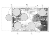
- FIGs. 3A-3D depict an example for illustrating an outline of a full spherical (or omnidirectional) image 6 that is displayed on a background image B in a manner of being superimposed on the background image B.
- FIG. 3A depicts an example of a full spherical (or omnidirectional) image 6 (an example of first image data)
- FIG. 3B depicts an example of a background image B (an example of second image data).
- full spherical (or omnidirectional) images 6 are classified into two types.
- an image includes nontransparent areas 6a in a transparent layer of a 360-degree (4 ⁇ -radian) image.
- an image includes a transparent area in a 360-degree (4 ⁇ -radian) image.
- a transparent area is provided in the second type.
- an image is expressed with the use of projection such as equirectangular projection to express a sphere as a plane, as depicted in FIGs. 3A-3D. Therefore, FIG. 3A has a horizontal 360-degree width and a vertical 180-degree height.
- FIGs. 3A and 3D are for the purpose of explanation and depict an area having the same size as the background image B (see FIG. 3B, for example).
- the full spherical (or omnidirectional) image 6 is larger than the advertisement space 7 (see FIGs. 3C and 3D, for example).
- the background image B depicted in FIG. 3B is approximately the same size as the advertisement space 7 and is smaller than the equirectangular projection image.
- the background image B is regularly displayed at the advertisement space 7 in its entirety, and a portion of the full spherical (or omnidirectional) image 6 (i.e., a predetermined area image Q in FIG. 1A) overlapping the background image B is displayed at the advertisement space 7.
- a full spherical (or omnidirectional) image 6 has a structure in which nontransparent areas 6a are provided in a transparent layer.
- a full spherical (or omnidirectional) image 6 is generally transparent and partially nontransparent.
- the nontransparent areas 6a in FIG. 3A are simple circles, but the nontransparent areas 6a may include any content (image or text, for example).
- a full spherical (or omnidirectional) image 6 and a background image B are delivered to the terminal apparatus 30.
- FIGs. 3C and 3D depict images displayed at advertisement spaces 7 by the terminal apparatus 30.
- the terminal apparatus 30 displays a full spherical (or omnidirectional) image 6 on a background image B in a manner of superimposing the full spherical (or omnidirectional) image 6 on the background image B.
- the full spherical (or omnidirectional) image 6 is approximately transparent for the entire area, only nontransparent areas 6a are actually displayed in a manner of being superimposed on the background image B.
- the full spherical (or omnidirectional) image 6 is wider than the advertisement space 7 and wider than the background image B, in FIG. 3C, one nontransparent area 6a at the right end is outside the display range.
- FIG. 3D depicts a state in which the full spherical (or omnidirectional) image 6 is rotated (moved) to the left viewed from the viewer.
- the background image B is not changed whereas the nontransparent areas 6a displayed at the advertisement space 7 (which are included in the field angle as a predetermined area T (see FIG. 1A)) are moved to the left. Therefore, in FIG. 3D, the one nontransparent area 6a at the left end is out of the display range.
- the content is a character of a game, for example, the character appears to be moving (walking) in the background image B.
- the image display system 100 of the present embodiment provides an image viewing experience in which a full spherical (or omnidirectional) image 6 not only rotates but also moves relative to a background image B by making the full spherical (or omnidirectional) image 6 that can be rotated up, down, left, or right partially nontransparent and superimposing the partial nontransparent areas on the background image B.
- a designer creates a background image B by using equirectangular projection and arranges a character on the background image B.
- a background image B is prepared as a plane image, and a full spherical (or omnidirectional) image 6 including a character is superimposed, so that movement of the character can be provided.
- the character appears to be in the vicinity of a companion drawn in the background image B, and when the full spherical (or omnidirectional) image 6 rotates (moves), the character moves relative to the background image B, making the character appear to be in the vicinity of an enemy drawn in the background image B.
- the full spherical (or omnidirectional) image 6 rotates (moves)
- the character moves relative to the background image B, making the character appear to be in the vicinity of an enemy drawn in the background image B.
- a full spherical (or omnidirectional) image 6 is an example of an image in which nontransparent areas 6a are provided in a transparent layer of 360 degrees (4 ⁇ radians) and also, may be an example of an image captured by an omnidirectional camera as depicted in FIG. 18A that will be described later.
- a simple planar image may be used instead of a full spherical (or omnidirectional) image 6.
- Advertisement effectiveness means at least attracting attention, and also, causing a viewer to make a click (or a tap) may be referred to as advertisement effectiveness.
- First image data being associated with second image data means that both sets of image data are delivered to the same terminal apparatus 30.
- plural sets of second image data may be associated with a single set of first image data
- plural sets of first image data may be associated with a single set of second image data.
- Transparent may mean translucent in addition to meaning completely transparent.
- first image data and second image data are superimposed together
- the first image data including a transparent area is in front of the viewer and the second image data is in the back.
- the relative position of superimposing and whether to previously extract a superimposing image are optional.
- an image may be displayed not only at a display space but also over the entire screen (display).
- FIG. 4 depicts an example of a schematic configuration diagram of the image display system 100.
- the image display system 100 includes the terminal apparatus 30, the image delivery apparatus 10, the DSP 20, an SSP (Supply Side Platform) 50, a partner site Web server 60, and an advertiser Web server 70 each being capable of communicating via a network N.
- SSP Service Side Platform
- the network N includes a LAN provided in a facility in which the terminal apparatus 30 is installed, a provider network of a provider connecting the LAN to the Internet, and a circuit provided by a circuit provider.
- the network N includes a plurality of LANs, the network N is called a WAN or the Internet.
- the network N may be provided either as a wired or wireless system, and may be provided as a combination of a wired system and a wireless system.
- the terminal apparatus 30 can be connected to the provider network without using a LAN.
- the terminal apparatus 30 is an information processing apparatus that operates as a client terminal according to the present embodiment.
- browser software or application software having functions equivalent to the functions of browser software operates, and a Web page requested by the terminal apparatus 30 is received from the partner site Web server 60 and displayed on a display of the terminal apparatus 30.
- the terminal apparatus 30 is, for example, a PC (Personal Computer), a tablet computer, a smartphone, a PDA (Personal Digital Assistant), a game machine, a navigation terminal, a wearable PC, or the like, and may be any apparatus as long as the apparatus can display a Web page.
- a printer may be used as the terminal apparatus 30.
- a digital signage may be used to display a Web page.
- a digital signage refers to a system or a display apparatus that transmits information using an electronic display device, such as a display, at a location where persons pass through or are present, such as outdoors, a store, a public space, or a transportation facility; or refers to information displayed by the system or the display apparatus.
- a Web application is included in a Web page.
- a Web application is software or a mechanism used on a Web browser that works by coordinating a program in a programming language (e.g., JavaScript) running on a Web browser with a program on a Web server.
- a programming language e.g., JavaScript
- an application that depends on an OS called a native application may be used to be caused to operate in the same manner.
- the terminal apparatus 30 may be connected to the network N via an access point of a wired or wireless LAN, or may be connected to the network N via switched circuit communication such as 3G, 4G, or LTE (Long Term Evolution).
- switched circuit communication such as 3G, 4G, or LTE (Long Term Evolution).
- the partner site Web server 60 is a server (a conventional information processing apparatus) that provides information and functions to a client computer (terminal apparatus 30 according to the present embodiment) used by a viewer through a network.
- a Web page provided by the partner site Web server 60 has an advertisement space 7.
- the partner site Web server 60 requests the SSP 50 to display an advertisement at the advertisement space 7. This allows the advertisement space 7 to be associated with an advertisement tag issued by the SSP 50.
- the advertiser Web server 70 is also a server (a conventional information processing apparatus) that provides information and functions to a client computer (terminal apparatus 30 according to the present embodiment) used by a viewer through a network.
- An advertiser requests the DSP 20 to purchase an advertisement space 7.
- the advertiser registers the image delivery apparatus 10 where advertisement data is stored with the DSP 20.
- the advertiser provides the advertisement data to the image delivery apparatus 10.
- the URL of a Web site (a landing page) desired to be viewed by a viewer such as an advertiser Web server 70 is registered in the advertisement data (i.e., the URL is linked with the advertisement data).
- the advertiser Web server 70 and the partner site Web server 60 communicate with the terminal apparatus 30 using, for example, a HTTP or HTTPs communication protocol.
- the advertiser Web server 70 and the partner site Web server 60 transmit screen page information to the terminal apparatus 30.
- Screen page information is a program written with the use of HTML, a scripting language, and a CSS (cascading style sheet), where the structure of a Web page is predominantly specified by the HTML, the scripting language defines the operations of the Web page, and the CSS identifies the style of the Web page.
- it is a scripting language that reflects the viewer’s operation on the Web page in a full spherical (or omnidirectional) image 6.
- a programming language such as JavaScript (registered trademark) or ECMAScript is known.
- the advertiser Web server 70 and the partner site Web server 60 both record cookies in the browser software of the terminal apparatus 30.
- the advertiser Web server 70 records both its own cookie and a cookie of the DSP 20
- the partner site Web server 60 records both its own cookie and a cookie of the SSP 50.
- the SSP 50 is a mechanism for maximizing profit as a result of the partner site Web server 60 that displays an advertisement space 7 selling the advertisement space 7.
- FIG. 4 depicts the SSP 50 as a single information processing apparatus, the SSP 50 is a network including one or more information processing apparatuses.
- the partner site Web server 60 requests the SSP 50 to sell an advertisement space 7. Specifically, an advertisement tag provided by the SSP 50 is described in an advertisement space 7, and when the terminal apparatus 30 displays a Web page of the partner site Web server 60, the SSP 50 is requested on the basis of the advertisement tag to deliver the corresponding advertisement (an advertisement request).
- the SSP 50 receives a bid for the advertisement space 7 from the DSP 20 and transmits, to the terminal apparatus 30, access information 1 for accessing the DSP 20 that is the successful bidder.
- the DSP 20 is a mechanism for an advertiser to perform efficiently and effectively delivery of an advertisement such as purchasing an advertisement space 7 and delivering an advertisement.
- FIG. 4 depicts the DSP 20 as a single information processing apparatus, the DSP 20 is a network including one or more information processing apparatuses.
- the DSP 20 obtains a cookie (referred to as a SSP cookie to distinguish from a DSP cookie) from the SSP 50 and determines the attribute and so forth of a viewer based on information concerning association between the DSP cookie and the SSP cookie managed by the DSP 20. Then, the DSP 20 bids on the SSP 50 at a price determined based on the advertiser’s delivery settings and based on the viewer’s attribute, budget, and so forth.
- the DSP 20 that is the successful bidder is requested by the terminal apparatus 30 with the use of access information 1 for an advertisement.
- the DSP 20 provides the image delivery apparatus 10 with the advertisement request and obtains access information 2 for the terminal apparatus 30 to request advertisement data from the image delivery apparatus 10.
- the advertisement data includes a display program for displaying a full spherical (or omnidirectional) image 6 and a viewer’s operation history program for obtaining a viewer’s operation history.
- the DSP 20 transmits the access information 2 to the terminal apparatus 30.
- the DSP 20 charges the advertiser in accordance with the contract. Between the image delivery apparatus 10 and the advertiser, charging in accordance with the contract is performed. In this regard, whether a charge is issued for an advertisement only when the advertisement is displayed, for example, depends on the contract.
- the image delivery apparatus 10 is one or more information processing apparatuses that provide advertisement data including an advertisement material (a full spherical (or omnidirectional) image 6) suitable for the viewers’ attributes to the advertisement space 7 purchased by the DSP 20.
- the image delivery apparatus 10 stores provided materials such as banners, text, and advertisement images.
- Advertisement data may be merely a banner (text, photograph, or pictorial image) or may include a scripting language in addition to an image.
- the display program for rotating a full spherical (or omnidirectional) image 6 in a display order (described later) and reflecting an operation of a viewer in the appearance of the full spherical (or omnidirectional) image 6, and the viewer’s operation history program for recording a viewer’s operation on the full spherical (or omnidirectional) image 6 are included in the advertisement data.
- These programs are written in a scripting language.
- the image delivery apparatus 10 transmits the advertisement data to the terminal apparatus 30.
- the advertisement data includes the full spherical (or omnidirectional) image 6, which is, by the display program, automatically rotated to trace attention points, and increased or reduced in size.
- the viewer’s operation history program transmits the viewer’s operation history with respect to the full spherical (or omnidirectional) image 6 together with a cookie (referred to as an image cookie for distinguishing) of the image delivery apparatus 10 and an image ID of the full spherical (or omnidirectional) image 6 to the image delivery apparatus 10.
- the image cookie is written to the browser software by the image delivery apparatus 10.
- the viewer’s operation history is, for example, information as to which viewed angle has been displayed. Because the viewer’s operation history is used to identify attention points, the viewer’s operation history need not be transmitted for a case where the viewer’s operation history is not used to identify attention points.
- the viewer’s operation history program transmits a fact that a click has been performed together with a pattern ID of a display pattern (described later) to the image delivery apparatus 10.
- the image delivery apparatus 10 previously determines a plurality of display patterns for one full spherical (or omnidirectional) image 6. By monitoring the click rate of each display pattern, it becomes possible to deliver only the display pattern having the high click rate.
- the hardware configuration of the advertiser Web server 70, the partner site Web server 60, the image delivery apparatus 10, the SSP 50, and the DSP 20 in the image display system according to the present embodiment will be described.
- the advertiser Web server 70, the partner site Web server 60, the image delivery apparatus 10, the SSP 50, and the DSP 20 are implemented, for example, by computer systems each having a hardware configuration depicted in FIG. 5.
- FIG. 5 is an example of a hardware configuration of a computer system 200 according to the present embodiment.
- the computer system 200 depicted in FIG. 5 includes an input device 201, a display device 202, an external I/F 203, a RAM (Random Access Memory) 204, a ROM (Read-Only Memory) 205, a CPU (Central Processing Unit) 206, a communication I/F 207, and an HDD (Hard Disk Drive) 208, each of which is connected to each other by a bus 209.
- an input device 201 includes an input device 201, a display device 202, an external I/F 203, a RAM (Random Access Memory) 204, a ROM (Read-Only Memory) 205, a CPU (Central Processing Unit) 206, a communication I/F 207, and an HDD (Hard Disk Drive) 208, each of which is connected to each other by a bus 209.
- the input device 201 includes a keyboard, a mouse, a touch panel, or the like, and is used by an operator to input various operation signals.
- the display device 202 includes a display or the like to display the results of processes performed by the computer system 200.
- the communication I/F 207 is an interface that connects the computer system 200 to an intranet, the Internet, or the like. This allows the computer system 200 to perform data communication via the communication I/F 207.
- the HDD 208 is a non-volatile storage device that stores programs and data. Examples of the programs and data to be stored include an operating system (OS), which is basic software for controlling the entire computer system 200, and application software that provides various functions on the OS.
- OS operating system
- the HDD 208 manages the stored programs 208p and data using a predetermined file system and/or database.
- the external I/F 203 is an interface for an external device.
- the external device may be a recording medium 203a, for example. This allows the computer system 200 to read information from and/or write information to the recording medium 203a via the external I/F 203.
- the recording medium 203a may be any one of a flexible disk, a CD (Compact Disk), a DVD (Digital Versatile Disk), an SD memory card, and a universal serial bus memory (USB memory), for example.
- the ROM 205 is a non-volatile semiconductor memory (storage device) that can store programs and data even when the power is turned off.
- the ROM 205 stores programs and data such as a BIOS (Basic Input/Output System) that is executed when the computer system 200 is started, OS settings, and network settings.
- BIOS Basic Input/Output System
- the RAM 204 is a volatile semiconductor memory (storage device) that temporarily stores programs and data.
- the CPU 206 is an arithmetic and logic device which implements control of the entire computer system 200 and various functions by reading programs and data from storage devices such as the ROM 205 and the HDD 208 to the RAM 204 and executing processes.
- Each server may be compatible with cloud computing, and may be a stand-alone information processing apparatus.
- Cloud computing is a mode of using resources on a network without being aware of particular hardware resources.
- FIG. 6 depicts an example of a hardware configuration of the terminal apparatus 30.
- the terminal apparatus 30 depicted in FIG. 6 may be a tablet computer or a smartphone.
- the terminal apparatus 30 includes a CPU 601, a ROM 602, a RAM 603, an EEPROM 604, a CMOS sensor 605, an acceleration and direction sensor 606, and a medium drive 608.
- the CPU 601 controls operation of the entirety of the terminal apparatus 30.
- the ROM 602 stores a BIOS.
- the RAM 603 is used as a work area of the CPU 601.
- the EEPROM 604 reads data and writes data under the control of the CPU 601.
- the CMOS sensor 605 captures an image of an object under the control of the CPU 601 to obtain image data.
- the acceleration and direction sensor 606 is an electromagnetic compass, gyrocompass, acceleration sensor, or the like that detects terrestrial magnetism.
- the medium drive 608 controls reading data from or writing (storing) data to a medium 607, such as a flash memory.
- a medium 607 such as a flash memory.
- the medium 607 from which already written (stored) data is read or to which data is newly written (stored) is detachable.
- Programs 604p to be executed by the CPU 601 are stored in the EEPROM 604.
- the programs 604p are application software, an OS, and so forth for executing various processes of the present embodiment.
- the programs 604p may be delivered in a form of being stored in the medium 607 or from a program delivery server.
- the CMOS sensor 605 is a charge-coupled device that converts light into an electric charge to convert an image of an object into electronic data.
- the CMOS sensor 605 may be replaced with, for example, a CCD (Charge Coupled Device) sensor as long as the sensor can capture an image of an object.
- the CMOS sensor 605 can read bar codes and two-dimensional bar codes.
- the terminal apparatus 30 further includes an RF tag reader/writer 622, an antenna I/F 623, and a vibration actuator 624.
- the RF tag reader/writer 622 performs communication according to a standard such as, for example, NFC (Near Field Communication).
- the vibration actuator 624 is a motor that vibrates the terminal apparatus 30. For example, in response to receiving an incoming call or mail, the vibration actuator 624 alerts the viewer by vibrating the terminal apparatus 30.
- the terminal apparatus 30 further includes a sound input unit 609, a sound output unit 610, an antenna 611, a communication unit 612, a wireless LAN communication unit 613, a short range wireless communication antenna 614, a short range wireless communication unit 615, a display 616, a touch panel 617, and a bus line 619.
- the sound input unit 609 converts a sound into a sound signal.
- the sound output unit 610 converts a sound signal to a sound.
- the communication unit 612 communicates with the nearest base station device by a radio communication signal using the antenna 611.
- the wireless LAN communication unit 613 performs wireless LAN communication conforming to the IEEE 802.11 standard.
- the short range wireless communication unit 615 is a communication device that uses the antenna 614 for short range wireless communication and complies with, for example, the communication standard of Bluetooth (trademark) or Bluetooth Low Energy (trademark).
- the display 616 is a liquid crystal device or an organic EL for displaying an image of an object, various icons, or the like.
- the touch panel 617 is mounted on the display 616 and includes a pressure-sensitive or electrostatic panel that detects a touch position on the display 616 in response to being touched with a finger, a touch pen, or the like.
- the bus line 619 includes an address bus, a data bus, and so forth for electrically connecting the units together.
- the terminal apparatus 30 further includes a dedicated battery 618 and may be driven by either the battery 618 or a commercial power supply.
- the sound input unit 609 includes a microphone for inputting a sound.
- the sound output unit 610 includes a speaker that outputs a sound.
- FIG. 7 depicts an image of using an omnidirectional camera 9.
- the omnidirectional camera 9 is an image capturing device for a user to hold by the user’s hand for capturing an image of an object around the user, as depicted in FIG. 7.
- the omnidirectional camera 9 has a structure in which the rear surfaces of two image capturing elements face each other. The image capturing elements capture two respective hemispherical images of an object around the user.
- FIG. 8A depicts a hemispherical image (the front side)
- FIG. 8B depicts a hemispherical image (the rear side)
- FIG. 8C depicts an image (an equirectangular projection image) expressed by equirectangular projection.
- FIG. 9A depicts a concept of a sphere being covered by an equirectangular projection image
- FIG. 9B depicts a full spherical (or omnidirectional) image 6.
- an image obtained by the omnidirectional camera 9 is a hemispherical image (the front side) curved because of a fish-eye lens.
- an image obtained by the omnidirectional camera 9 is a hemispherical image (the rear side) curved because of a fish-eye lens.
- the hemispherical image (the front side) and the 180-degree inverted hemispherical image (the rear side) are combined by the omnidirectional camera 9; thus, an equirectangular projection image is generated as depicted in FIG. 8C, which is a full spherical (or omnidirectional) image.
- an OpenGL ES Open Graphics Library for Embedded Systems
- an OpenGL ES Open Graphics Library for Embedded Systems
- the full spherical (or omnidirectional) image 6 is expressed as an image such as the equirectangular projection image facing the center of the sphere.
- An OpenGL ES is a graphical library used to visualize 2D (2-Dimensional) data or 3D (3-Dimensionnal) data.
- the full spherical (or omnidirectional) image 6 may be a still image or a moving image.
- Advertisement data delivered by the image delivery apparatus 10 includes such a full spherical (or omnidirectional) image 6.
- a full spherical (or omnidirectional) image 6 is curved because the full spherical (or omnidirectional) image is an image pasted over a spherical surface. Therefore, when such a full spherical (or omnidirectional) image is viewed from a human eye, the viewer may have a feeling of discomfort. Therefore, the terminal apparatus 30 displays a predetermined area T that is a portion of a full spherical (or omnidirectional) image 6 as a plane image having a low curvature so as not to provide a discomfort feeling to the viewer.
- the predetermined area T is expressed by coordinates (X, Y, Z) of a three-dimensional virtual space.
- the terminal apparatus 30 cannot display the predetermined area T as it is. Therefore, the terminal apparatus 30 converts the predetermined area T using perspective projection transformation to project a three-dimensional object to a two-dimensional plane using a 3D computer graphics technique.
- FIG. 10 depicts an example for illustrating the visual axis of a viewer.
- the visual axis is identified by information identifying coordinates of a sphere, such as three-dimensional coordinates or latitude and longitude, for example.
- the center point CP of the predetermined area T corresponds to the visual axis.
- the center point CP of the predetermined area T is identified by a spherical coordinate system ( ⁇ , ⁇ ). ⁇ denotes longitude and ⁇ denotes latitude.
- the viewer can change the visual axis by the viewer’s operation.
- the virtual camera IC as a rigid body can be rotated in three ways: roll (rotation about the Z axis), yaw (rotation about the Y axis), and pitch (rotation about the X axis). Any of these three rotations cause a change in the visual axis.
- the yaw angle changes when the viewer rotates the full spherical (or omnidirectional) image 6 horizontally
- the pitch angle changes when the viewer rotates the full spherical (or omnidirectional) image 6 vertically
- the roll angle changes when the viewer rotates the full spherical (or omnidirectional) image 6 about the axis that is the center axis of the display 616.
- a viewer’s operation of a Web page is reflected in the visual axis (roll angle, yaw angle, and pitch angle).
- a specific manner as to how a viewer’s operation of a Web page is reflected in the visual axis is prescribed in the display program. It is also possible to increase and reduce the size of the predetermined area T.
- the viewer can change the visual axis (rotate image data) by performing a flick upward, downward, leftward, and rightward on the advertisement space 7.
- FIG. 11 depicts an example of relationships between predetermined area information and an image of the predetermined area T.
- rH denotes horizontal radian (longitude ⁇ )
- rV denotes vertical radian (latitude ⁇ )
- ⁇ denotes a field angle. That is, the orientation of the virtual camera IC is adjusted so that the gaze point of the virtual camera IC indicated by the image capturing direction ( ⁇ , ⁇ ) becomes the same as the center point CP of the predetermined area T that is the image capturing area of the virtual camera IC.
- the predetermined area image Q is an image at the predetermined area T in the full spherical (or omnidirectional) image 6.
- f denotes the distance from the virtual camera IC to the center point CP.
- L denotes the distance between any vertex of the predetermined area T and the center point CP (2L denotes a diagonal).
- the trigonometric function expressed by the following equation (A) holds.
- FIGs. 12A-12C depict examples for schematically illustrating information used by a Web page.
- FIG. 12A depicts a Web page provided by the partner site Web server 60.
- a Web page provided by the partner site Web server 60 has one or more advertisement spaces 7.
- the browser of the terminal apparatus 30 has a SSP cookie and a DSP cookie beforehand.
- the URL of the SSP 50 and an advertisement space ID are associated with an advertisement space 7.
- the browser of the terminal apparatus 30 (an advertisement space detecting unit 36, which will be described later) transmits the SSP cookie and request contents to the SSP 50.
- access information 1 including the URL of the DSP 20 that is the successful bidder of an advertisement space 7 and a successful bid ID are transmitted from the SSP 50 to the terminal apparatus 30.
- FIG. 12B depicts an example for illustrating operations based on access information 1.
- the terminal apparatus 30 transmits a successful bid ID and a DSP cookie to the DSP 20 based on the URL of the DSP 20.
- the DSP 20 identifies an advertisement request using the successful bid ID and obtains the URL of the image delivery apparatus 10 and access information 2 including an advertisement opportunity ID from the image delivery apparatus 10.
- the terminal apparatus 30 obtains the access information 2 and the advertisement opportunity ID from the DSP 20.
- FIG. 12C depicts an example for illustrating operations based on the access information 2.
- the terminal apparatus 30 transmits the advertisement opportunity ID to the image delivery apparatus 10 based on the URL of the image delivery apparatus 10.
- the image delivery apparatus 10 generates advertisement data based on the advertisement request identified with the use of the advertisement opportunity ID and transmits the advertisement data together with an image cookie, the advertisement space ID, and a display pattern to the terminal apparatus 30.
- a full spherical (or omnidirectional) image 6 is displayed at the advertisement space 7 of the Web page.
- FIGs. 13A and 13B depict an example of a functional block diagram depicting functions of the terminal apparatus 30, the advertiser Web server 70, the partner site Web server 60, the image delivery apparatus 10, the SSP 50, and the DSP 20.
- the advertiser Web server 70 and the partner site Web server 60 each include a Web page providing unit 71.
- Each of these functions of the advertiser Web server 70 and the partner site Web server 60 is a function or a unit implemented by the CPU 206 executing the program 208p read from the HDD 208 to the RAM 204.
- the Web page providing unit 71 performs conventional HTTP communication and generates a Web page in response to a Web page request from the terminal apparatus 30 and transmits the Web page to the terminal apparatus 30.
- the Web page providing unit 71 may request an application server to perform a process, set the process result at a Web page, and transmit the Web page.
- a Web page of the advertiser Web server 70 includes an advertiser’s cookie and a DSP cookie. This is because the advertiser Web server 70 requests the DSP 20 to deliver an advertisement. This makes it possible to implement a retargeting advertisement, for example.
- a Web page of the partner site Web server 60 includes a partner site cookie and a SSP cookie. This is because the partner site Web server 60 requests the SSP 50 to sell an advertisement space 7. ⁇ SSP>>
- the SSP 50 includes an advertisement request unit 51, an advertisement demand obtaining unit 52, an access information transmitting unit 53, and a successful bid determining unit 54.
- Each of these functions of the SSP 50 is a function or a unit implemented by the CPU 206 executing the program 208p read from the HDD 208 to the RAM 204.
- the advertisement demand obtaining unit 52 obtains an advertisement request that is sent by the terminal apparatus 30 together with a SSP cookie as a result of the terminal apparatus 30 executing an advertisement tag corresponding to an advertisement space 7.
- the advertisement demand obtaining unit 52 sends the advertisement request including the SSP cookie to the advertisement request unit 51.
- the advertisement request unit 51 transmits the advertisement request to the DSP 20.
- the advertisement request may include the SSP cookies, the domain of the partner site Web server 60, the advertisement space ID, the size of the advertisement space, an advertisement format, the browser type, and the OS types, for example.
- the successful bid determining unit 54 receives a bid from the DSP 20 and performs an auction to basically sell the advertisement space 7 to the DSP 20 offering the highest bid amount. In this regard, the successful bid determining unit 54 may avoid receiving the bid depending on the advertiser’s product or service. The successful bid determining unit 54 generates a successful bid ID and provides the successful bid ID to the DSP 20.
- the access information transmitting unit 53 generates access information 1 for requesting an advertisement to the DSP 20 that is the successful bidder and transmits the access information 1 together with the successful bid ID to the terminal apparatus 30.
- the access information 1 includes the URL (IP address) of the DSP 20.
- the DSP 20 includes a request receiving unit 21, a bid determining unit 22, a bid unit 23, an advertisement demand receiving unit 24, and an image request unit 25.
- Each of these functions of the DSP 20 is a function or a unit implemented by the CPU 206 executing the program 208p read from the HDD 208 to the RAM 204.
- a cookie information DB 291 and a delivery setting DB 292 are provided in a storage unit 29.
- the storage unit 29 is implemented by the HDD 208 or the RAM 204 depicted in FIG. 5.
- Table 1 schematically depicts information stored in the cookie information DB 291.
- the cookie information DB 291 associates a DSP cookie with a SSP cookie and registers a viewer’s visited domain. Associating a DSP cookie with a SSP cookie is implementable by a technique called cookie sync.
- a visited domain can be obtained as a result of a viewer visiting a Web site to which the DSP 20 has pasted a tag (a behavioral monitoring tag).
- the DSP 20 can identify a DSP cookie from a SSP cookie and determine which Web site the viewer is interested in.
- Table 2 schematically depicts information stored in the delivery setting DB 292.
- the delivery setting DB 292 registers advertiser IDs, advertisement target attributes (attributes of desirable targets), and non-advertisement target attributes (attributes of undesirable targets).
- Advertiser IDs are identification information to identify advertisers who provide wide angle images. Therefore, the DSP 20 or the image delivery apparatus 10 can determine whether to transmit a wide angle image by referring to the attributes of desirable targets or the attributes of undesirable targets set for the advertiser who provides the wide angle image.
- ID is an abbreviation of identification and means an identifier or identification information.
- An ID is a name, a code, a character string, a numeric value, or a combination of one or more of these expressions, used to uniquely distinguish a particular object from a plurality of objects. The same applies to IDs that will be described hereinafter.
- Advertisement target attributes are attributes of viewers to whom an advertiser desires to deliver an advertisement.
- Non-advertisement target attributes are attributes of viewers to whom an advertiser does not desire to deliver an advertisement.
- the DSP 20 quantifies the attributes of viewers by comparing the attributes of viewers determined from the cookie information DB 291, for example, with the information of the delivery setting DB 292, and determines a bid amount. For determining a bid amount, various information such as the time, the day of week, and the area of the viewers, for example, may be considered. (Functions of DSP)
- the request receiving unit 21 receives an advertisement request from the SSP 50. From the request information, basic information such as an advertisement space ID of the terminal apparatuses 30 can be obtained.
- the bid determining unit 22 evaluates the advertisement request received by the request receiving unit 21 by referring to the cookie information DB 291 and the delivery setting DB 292 to determine a bid amount. In some cases, the DSP does not perform bidding in response to the advertisement request. As described above, a DSP cookie is identified from a SSP cookie, and a bid amount is determined by how much attribute information stored in association with the DSP cookie matches the advertiser’s request stored in the delivery setting DB 292.
- the bid unit 23 bids to the SSP 50 with the determined bid amount. In a case of a successful bid, the bid unit 23 obtains a successful bid ID and associates the successful bid ID with the advertisement request.
- the advertisement demand receiving unit 24 obtains an advertisement demand (including the successful bid ID and the DSP cookie) from the terminal apparatus 30 based on access information 1.
- the advertisement demand receiving unit 24 identifies the advertisement request from the successful bid ID.
- the DSP cookie need not be used and is used when the SSP cookie and the DSP cookie are not associated together.
- the image request unit 25 requests, from the image delivery apparatus 10, access information 2 as well as the DSP cookie, an advertiser ID, and request contents.
- the advertiser is identified from the advertiser ID.
- the advertisement space ID included in the request contents is used to identify the advertisement space 7.
- the attributes of the viewers may be further transmitted to the image delivery apparatus 10. Thereby, the image delivery apparatus 10 can deliver a full spherical (or omnidirectional) image 6 suitable for the viewers.
- the terminal apparatus 30 includes a Web page obtaining unit 31, a Web page analyzing unit 32, a Web page display unit 33, a viewer’s operation receiving unit 34, and a script executing unit 35.
- Each of these functions of the terminal apparatus 30 is a function or a unit implemented by the CPU 601 executing the program 604p read from the EEPROM 604 to the RAM 603.
- the viewer’s operation receiving unit 34 receives various viewer’s operations on the terminal apparatus 30. For example, an operation on the browser implemented by the terminal apparatus 30 is received.
- the viewer’s operation receiving unit 34 receives an operation on a Web page.
- a viewer’s image operation receiving unit 43 receives a viewer’s operation on image data based on a script.
- the Web page obtaining unit 31 obtains Web pages from the advertiser Web server 70 and the partner site Web server 60 in communication with the advertiser Web server 70 and the partner site Web server 60 in response to an operation of the viewer on the terminal apparatus 30 or in response to an operation of a script.
- the Web page analyzing unit 32 reads HTML included in screen page information sequentially from the top to the bottom and analyzes the structure of the text or the image data included in the HTML. The Web page analyzing unit 32 also detects the association of the HTML with the text or image data described in the CSS and associates the style of the text or image data included in the HTML with the text or image data. The Web page analyzing unit 32 detects a script tag from the HTML and extracts a script written in a scripting language. The Web page analyzing unit 32 transmits the HTML and the CSS to the Web page display unit 33 and transmits the script to the script executing unit 35.
- the Web page display unit 33 displays the Web pages on the display 616 in the order of completion of the analysis from the beginning of the HTML.
- the Web page display unit 33 updates the Web pages according to the viewer’s operations on the Web pages.
- the script executing unit 35 executes the script extracted by the Web page analyzing unit 32.
- the actual contents of a script vary depending on a Web page.
- the script the advertisement tag associated with the advertisement space 7, the access information 1 obtained from the SSP 50, the access information 2 obtained from the DSP 20, and the advertisement data delivered from the image delivery apparatus 10 are detected.
- the script executing unit 35 is implemented by the CPU 601 executing the program 604p depicted in FIG. 6.
- the functions or units of the script executing unit 35 are implemented by the CPU 601 executing a script.
- the advertisement space detecting unit 36 is a function implemented as a result of the terminal apparatus 30 executing the advertisement tag associated with the advertisement space 7 included in the screen page information obtained by the Web page obtaining unit 31.
- the advertisement space detecting unit 36 transmits the advertisement request to the SSP 50 together with the SSP cookie on the basis of the URL associated with the advertisement space 7.
- the access information obtaining unit 37 obtains the access information 1 from the SSP 50.
- the access information 1 is written as a script.
- the advertisement demand unit 38 accesses the DSP 20 based on the URL included in the access information 1 and demands the advertisement together with the bid ID and the DSP cookie.
- the advertisement demand unit 38 obtains the access information 2 and the advertisement opportunity ID in response to the demand.
- the access information 2 is also written as a script.
- the advertisement obtaining unit 39 indicates the advertisement opportunity ID based on the URL of the image delivery apparatus 10 included in the access information 2 and demands the advertisement data from the image delivery apparatus 10. Because the image delivery apparatus 10 generates the advertisement data, the advertisement obtaining unit 39 obtains the advertisement data.
- Advertisement data of the present embodiment includes a full spherical (or omnidirectional) image 6 (or a three-dimensional computer graphics (3DCG) image), a display pattern, a display program, and a viewer’s operation history program. The viewer’s operation history program functions to transmit a viewer’s operation history to the image delivery apparatus 10.
- the display program rotates a full spherical (or omnidirectional) image 6 or a 3DCG image according to a display pattern and reflects a viewer’s operation on the appearance of the full spherical (or omnidirectional) image 6 or the 3DCG image.
- the viewer’s operation history program and the display program are also described in a scripting language and are executed by the script executing unit 35.
- the advertisement display unit 40 displays the advertisement data obtained from the image delivery apparatus 10.
- the advertisement display unit 40 is implemented mainly by the display program, and displays a full spherical (or omnidirectional) image 6 or a 3DCG image (i.e., an advertisement) at an advertisement space 7, and, in addition, rotates the image automatically.
- the appearance of a full spherical (or omnidirectional) image 6 is changed according to a viewer’s operation on the full spherical (or omnidirectional) image 6.
- the viewer’s image operation receiving unit 43 receives the viewer’s operation as an operation to the image data in preference to being received as an operation to the Web page. This allows the image data rather than the Web page to be changed in response to the viewer flicking, swiping, or pinching-in or pinching-out (for increasing or reducing in size) on the advertisement space 7.
- the terminal apparatus 30 obtains the image cookie of the image delivery apparatus 10 and stores the cookie in the storage unit 49.
- the advertisement obtaining unit 39 transmitting the image cookie to the image delivery apparatus 10, the image delivery apparatus 10 can associate the DSP cookie with the image cookie.
- a viewer’s operation history recording unit 41 is implemented mainly by the viewer’s operation history program and records operation information concerning the full spherical (or omnidirectional) image 6 or 3DCG as the viewer’s operation history. Details of the viewer’s operation history will be described in relation to the image delivery apparatus 10.
- a viewer’s operation history transmitting unit 42 is implemented mainly by the viewer’s operation history program and transmits the viewer’s operation history with respect to the full spherical (or omnidirectional) image 6 or 3DCG displayed at the advertisement space 7 to the image delivery apparatus 10 together with the image cookie and the image ID (identifying the full spherical (or omnidirectional) image 6). In response to the image being clicked on, the information is transmitted to the image delivery apparatus 10 together with the display pattern.
- the image delivery apparatus 10 includes an image information responding unit 11, an advertisement delivery unit 12, an attention point identifying unit 13, a viewer’s operation history obtaining unit 14, and a delivery image receiving unit 15.
- Each of these functions of the image delivery apparatus 10 is a function or a unit implemented by the CPU 206 executing the program 208p read from the HDD 208 to the RAM 204.
- the image delivery apparatus 10 includes a storage unit 19 implemented by the HDD 208 or the RAM 204 depicted in FIG. 5.
- a delivery history DB 191, a viewer’s operation history DB 192, a cookie correspondence DB 193, an advertisement image DB 194, a pattern DB 195, and the display program 196 are provided in the storage unit 19.
- Table 3 schematically depicts information stored in the viewer’s operation history DB 192.
- operation history DB 192 a history of each viewer as to which operation has been performed by the viewer on a full spherical (or omnidirectional) image 6 is recorded.
- operation history DB 192 items of an image ID, a viewed time, an image cookie, and viewed angles 1-3, are recorded.
- An image ID is information for identifying a full spherical (or omnidirectional) image 6.
- An image cookie provides information to determine the identity of the viewer operating the terminal apparatus 30 or the terminal apparatus 30 itself (an example of apparatus identification information). Viewed angles 1-3 are viewed angles when a viewer views a full spherical (or omnidirectional) image 6.
- a viewed period, whether or not the viewed angle has been increased, the increased viewed angle in the case of increase, and whether or not the viewed angle has been reduced are stored at the item of each of the viewed angles 1-3.
- the viewed angles 1-3 are viewed angles at which the viewer has kept the full spherical (or omnidirectional) image 6 unrotated for a predetermined period of time (for example, 1 second) or more.
- the viewer’s operation history recording unit 41 of the terminal apparatus 30 records the top three viewed angles with respect to the periods of having been kept unrotated.
- the top three viewed angles may be replaced by the top four or more viewed angles and may be replaced by the top one viewed angle.
- the viewer’s operation history recording unit 41 records whether or not the viewer has increased or reduced the viewed angle with respect to each of the viewed angles 1-3.
- the image delivery apparatus 10 may use such a viewer’s operation history to identify attention points P.
- an image cookie is associated with an image ID, it is possible to implement a retargeting advertisement.
- the viewed angle at the time of a click may be recorded in a viewer’s operation history.
- Table 4 schematically depicts information stored in the advertisement image DB 194.
- the advertisement image DB 194 stores information of full spherical (or omnidirectional) images 6 or 3DCG to be used as advertisements.
- advertiser IDs, image IDs, initial positions, priorities, and target attributes are registered. Because the DSP 20 determines an advertiser, an image to be delivered is determined, from among images that the advertiser desires to deliver, on the basis of at least one of the priorities and the degrees of agreement between the viewers’ attributes and the target attributes of Table 4.
- the initial position of a full spherical (or omnidirectional) image 6 is indicated at a time of delivery.
- An image ID is associated with a background image B and a full spherical (or omnidirectional) image 6 that are displayed in a superimposed manner.
- an image associated with an image cookie by the viewer’s operation history DB 192 is delivered.
- Table 5 schematically depicts information stored in the cookie correspondence DB 193.
- the cookie correspondence DB 193 associates DSP cookies with image cookies.
- a DSP cookie is provided by the DSP 20 and an image cookie is provided by the terminal apparatus 30.
- the image delivery apparatus 10 can determine a viewer using only a DSP cookie.
- Table 6 schematically depicts information registered in the pattern DB 195.
- the pattern DB 195 the order in which attention points P of a full spherical (or omnidirectional) image 6 or a 3DCG image are displayed and combinations of viewed angles are registered. The order and a combination of viewed angles are referred to as a display pattern.
- four coordinates 1 to 4 correspond to attention points P.
- the number of attention points P for one full spherical (or omnidirectional) image or 3DCG image may be not limited to four: the number of attention points P for one full spherical (or omnidirectional) image or 3DCG image may be less than or equal to three and may be more than or equal to five.
- the number of attention points P for one full spherical (or omnidirectional) image or 3DCG image may vary depending on the full spherical (or omnidirectional) image 6 or 3DCG image.
- the number of clicks is the number of clicks the viewer has made for each of these display patterns.
- a click is an example of a “predetermined operation”.
- the image delivery apparatus 10 displays the same full spherical (or omnidirectional) images 6 or 3DCG images with the same display pattern at a plurality of terminal apparatuses 30 and records any click occurring at the terminal apparatuses 30. With the use of the thus accumulated records, deliveries with display patterns having the low click rates can be gradually reduced. It is preferable to record the number of clicks on a viewers’ attribute basis (for example, gender, age, and family structures). Thus, it is possible to display a display pattern having a larger number of clicks with respect to a viewer’s attribute.
- Table 7 schematically depicts information registered in the delivery history DB 191.
- image IDs and display patterns of all the full spherical (or omnidirectional) images 6 or 3DCG images having been delivered are registered in association with image cookies.
- the image delivery apparatus 10 can obtain the image cookie from the terminal apparatus 30.
- the image delivery apparatus 10 can avoid delivering the same full spherical (or omnidirectional) image 6 or 3DCG image to the same viewer, and can avoid delivering the same full spherical (or omnidirectional) image 6 or 3DCG image with the same display pattern. It is also possible to use the information to implement retargeting delivery. (Functions of Image Delivery apparatus)
- the image information responding unit 11 provides the advertisement opportunity ID to the DSP cookie, the advertiser ID, and the request contents (mainly, the advertisement space ID) obtained from the DSP 20 and returns the advertisement opportunity ID to the DSP 20 together with the access information 2.
- the advertisement opportunity ID it is possible to identify the advertisement delivery opportunity for each advertisement space 7 of the terminal apparatus 30.
- the advertisement delivery unit 12 determines the full spherical (or omnidirectional) image 6 to be delivered and the display pattern in response to the advertisement data being demanded by the terminal apparatus 30 with the use of the advertisement opportunity ID.
- the advertisement delivery unit 12 determines the full spherical (or omnidirectional) image 6 or 3DCG image associated with the advertiser ID obtained from the DSP 20 using the advertisement image DB 194.
- the viewers’ attributes are considered.
- the viewers’ attributes may be provided by the DSP 20 or have been stored by the image delivery apparatus 10 in association with the image cookie.
- the advertisement delivery unit 12 determines the display pattern of the full spherical (or omnidirectional) image 6 with reference to the pattern DB 195.
- the display pattern having the highest number of clicks is determined, or any display pattern is determined from among the display patterns having the numbers of clicks each being greater than or equal to a threshold. It is preferable that also the viewers’ attributes be taken into account also at a time of determining the display pattern.
- the viewer’s operation history obtaining unit 14 obtains the viewer’s operation history together with the image cookie and the image ID from the terminal apparatus 30 and stores the obtained data in the viewer’s operation history DB 192.
- the viewer’s operation history includes two types of viewer’s operation histories, one type (occurrences of clicks) for identifying the attention points and the other type for updating the number of clicks.
- the viewer’s operation history recording unit 41 of the terminal apparatus 30 may be included in the image delivery apparatus 10. Because the viewer’s operation history recording unit 41 requires the viewer’s operation contents in a time series, it may be difficult for the image delivery apparatus 10 to obtain the viewer’s operation contents depending on the communication band or the like. In this regard, it is possible for the viewer’s operation history recording unit 41 of the terminal apparatus 30 to transmit only the final viewer’s operation history to the image delivery apparatus 10, thereby reducing the communication load.
- the attention point identifying unit 13 identifies the attention points P of the full spherical (or omnidirectional) image 6. Various methods for identifying the attention points P, such as a method of estimating the attention points by image processing, are considerable, and the details will be omitted.
- the attention point identifying unit 13 registers the display patterns using the identified attention points P in the pattern DB 195.
- the delivery image receiving unit 15 receives the image to be delivered by the image delivery apparatus 10 (that is, receives the provided advertisement). Referring to FIG. 14, a method of receiving the image by the delivery image receiving unit 15 will be described. In some cases, a full spherical (or omnidirectional) image 6 and a background image B are collectively referred to as a delivery image. ⁇ Delivered image reception>
- FIG. 14 is an example of a functional block diagram depicting functions of the delivery image receiving unit 15 and an image registering terminal 90.
- the delivery image receiving unit 15 includes a communication unit 151, a screen page information generating unit 152, and an image storage unit 153.
- the communication unit 151 communicates with the image registering terminal 90 using, for example, a communication protocol of HTTP or HTTPs.
- screen page information of a delivery image registering screen page for registering a delivery image in response to a request from the image registering terminal 90 is transmitted to the image registering terminal 90.
- the communication unit 151 receives an image delivered from the image registering terminal 90.
- the screen page information generating unit 152 generates the screen page information of the delivery image registering screen page for registering a delivery image depicted in FIG. 15.
- the image storage unit 153 stores a delivery image received by the communication unit 151 in an advertisement image DB 194.
- the image registering terminal 90 is, for example, a terminal operated by the advertiser or a person in charge of an agent (hereinafter, simply referred to as a “person in charge”), and is used to register a full spherical (or omnidirectional) image 6 and a background image B depicted in FIG. 3 as a delivery image in the image delivery apparatus 10.
- the image registering terminal 90 includes a communication unit 91, a display control unit 92, and a viewer’s operation receiving unit 93.
- the hardware configuration of the image registering terminal 90 may be the same as the hardware configuration of FIG. 5.
- the communication unit 91 receives the screen page information of the delivery image registering screen page from the delivery image receiving unit 15 and transmits a delivery image that has been input by the person in charge to the delivery image receiving unit 15.
- the display control unit 92 displays the screen page information of the delivery image registering screen page received by the communication unit 91 on the display of the image registering terminal 90.
- the viewer’s operation receiving unit 93 receives an operation of the person in charge (for a full spherical (or omnidirectional) image 6 and a background image B) performed onto the delivery image registering screen page.
- FIG. 15 depicts an example of the delivery image registering screen page 220 displayed on the display of the image registering terminal 90.
- the delivery image registering screen page 220 includes a preview screen area 221, a full spherical (or omnidirectional) image file selecting field 222, a background image file selecting field 223, an end superimposition button 224, a cancel button 225, and a create button 226.
- the full spherical (or omnidirectional) image file selecting field 222 is a field for the person in charge to select and set a file of a full spherical (or omnidirectional) image 6.
- the background image file selecting field 223 is for the person in charge to select and set a file of a background image B.
- a full spherical (or omnidirectional) image 6 selected from the full spherical (or omnidirectional) image file selection field 222 is displayed in the preview screen area 221 and the background image B selected from the background image file selection field 223 is displayed in the preview screen area 221.
- the end superimposition button 224 is a button for causing one of the full spherical (or omnidirectional) image 6 and the background image B not to be displayed. In response to the person in charge successively depressing the end superimposition button 224, only the full spherical (or omnidirectional) image 6, only the background image B, or both the full spherical (or omnidirectional) image 6 and the background image B are displayed.
- the person in charge arranges and combines the nontransparent areas 6a in a transparent layer of a full spherical (or omnidirectional) image in advance to generate a full spherical (or omnidirectional) image 6.
- the full spherical (or omnidirectional) image 6 is, for example, a full spherical (or omnidirectional) image having a transparent area 310 at a portion of the full spherical (or omnidirectional) image as depicted in FIG. 18A, which will be described later (i.e., the above-mentioned second type)
- the person in charge combines a transparent layer in order to provide the transparent area 310 at a predetermined area to generate a full spherical (or omnidirectional) image 6.
- the full spherical (or omnidirectional) image 6 at the preview screen area 221 is a predetermined area image, only a portion of the full spherical (or omnidirectional) image 6 is displayed.
- the person in charge may rotate the full spherical (or omnidirectional) image 6 to adjust an initial position of the nontransparent areas 6a (content).
- the initial position is the relative position of the full spherical (or omnidirectional) image 6 relative to the background image B when the terminal apparatus 30 displays the delivery image at the advertisement space 7 immediately after receiving the advertisement data from the image delivery apparatus 10.
- the person in charge can determine the initial position enhancing the advertising effectiveness.
- the terminal apparatus 30 receives the initial position of the full spherical (or omnidirectional) image 6 to be registered in the terminal apparatus 30.
- FIG. 16 is an example of a sequence diagram depicting a procedure for the image display system 100 to deliver a full spherical (or omnidirectional) image 6 to be displayed as an advertisement.
- step S1 a viewer first operates the terminal apparatus 30 to connect with the partner site Web server 60.
- the viewer’s operation receiving unit 34 of the terminal apparatus 30 receives the operation, and the Web page obtaining unit 31 obtains a Web page.
- step S2 the Web page analyzing unit 32 of the terminal apparatus 30 analyzes the Web page and extracts HTML, CSS, and script.
- the Web page display unit 33 displays the Web page on the basis of the HTML and CSS.
- the advertisement space detecting unit 36 of the terminal apparatus 30 transmits an advertisement request to the SSP 50 by executing an advertisement tag (script) associated with an advertisement space 7.
- the advertisement request may include, for example, a SSP cookie, the domain of the partner site Web server 60, an advertisement space ID, the size of the advertisement space 7, an advertisement format, a browser type, and an OS type.
- step S4 the advertisement demand obtaining unit 52 of the SSP 50 obtains the advertisement request, and the advertisement request unit 51 receives the advertisement request.
- the advertisement request unit 51 detects the SSP cookie and provides the DSP 20 with the advertisement request and sells the advertisement space 7.
- step S5 the request receiving unit 21 of the DSP 20 transmits the advertisement request to the bid determining unit 22.
- the bid determining unit 22 of the DSP 20 identifies the DSP cookie from the SSP cookie with reference to the cookie information DB 291.
- step S6 the bid determining unit 22 determines the attributes from the DSP cookie.
- the visited domains in the cookie information DB 291 may be read, and the viewers’ attribute information identified by the DSP cookie may be read, as appropriate.
- step S7 the bid determining unit 22 determines whether to transmit a wide angle image or a 3DCG image to the viewer on the basis of the attributes of the desired targets or the attributes of the undesirable targets set for the advertiser who provides the wide angle image or 3DCG image with reference to the delivery setting DB 292. For example, it is assumed that at least one advertiser is determined with respect to whom the advertisement will be delivered.
- step S8 the bid determining unit 22 determines a bid amount in accordance with, for example, the advertiser’s budget and the degree of agreement of the attributes.
- step S9 the bid unit 23 of the DSP 20 bids to the SSP 50.
- the successful bid determining unit 54 of the SSP 50 determines a DSP 20, from among a plurality of DSPs, which, in principle, offers the highest bid amount as the successful bidder.
- step S10 for example, the DSP 20 depicted in FIG. 16 is the successful bidder.
- the SSP 50 provides the DSP 20 with a successful bid ID.
- step S11 the access information transmitting unit 53 of the SSP 50 transmits access information 1 to the terminal apparatus 30 together with the successful bid ID.
- step S12 the advertisement demand unit 38 of the terminal apparatus 30 transmits an advertisement demand to the DSP 20 together with the successful bid ID by executing the access information 1.
- step S13 the advertisement demand receiving unit 24 of the DSP 20 identifies the advertisement request from the successful bid ID.
- the image request unit 25 demands an image from the image delivery apparatus 10 using the advertiser ID, the DSP cookie, and the advertisement request.
- step S14 the image information responding unit 11 of the image delivery apparatus 10 generates an advertisement opportunity ID for identifying the advertisement request upon receipt of the image demand.
- step S15 The image information responding unit 11 transmits access information 2 associated with the advertisement opportunity ID to the DSP 20.
- step S16 the image request unit 25 of the DSP 20 receives the access information 2 and the advertisement demand receiving unit 24 transmits the access information 2 to the terminal apparatus 30.
- step S17 the advertisement obtaining unit 39 of the terminal apparatus 30 transmits an advertisement demand (including the advertisement opportunity ID) on the basis of the URL of the image delivery apparatus 10 included in the access information 2.
- the terminal apparatus 30 can transmit the image cookie.
- step S18 the advertisement delivery unit 12 of the image delivery apparatus 10 identifies the image demand from the advertisement opportunity ID.
- step S19 the advertisement delivery unit 12 identifies the attributes from the DSP cookie or identifies the attributes from the image cookie.
- the advertisement delivery unit 12 determines a full spherical (or omnidirectional) image 6 and a background image on the basis of the advertiser ID and the attributes.
- a full spherical (or omnidirectional) image 6 and a background image to be transmitted are determined on the basis of the attributes or the priorities of the delivery targets set to the full spherical (or omnidirectional) images 6 and the background images.
- the display pattern to be used is a display pattern having the number of clicks higher than the threshold number. However, the display pattern is selected randomly while the number of times of delivery of full spherical (or omnidirectional) images 6 and background images is small.
- the advertisement delivery unit 12 transmits advertisement data including the full spherical (or omnidirectional) image 6, the background image, the initial position, the display pattern, the image ID, the image cookie, and the advertisement space ID to the terminal apparatus 30.
- the URL of the advertiser Web server 70 is associated with the full spherical (or omnidirectional) image 6 or the background image.
- step S22 the advertisement obtaining unit 39 of the terminal apparatus 30 obtains the advertisement data, and the advertisement display unit 40 displays the full spherical (or omnidirectional) image 6 and the background image at the advertisement space 7.
- the viewer presses (clicks on or taps on) the advertisement space 7
- the viewer’s operation receiving unit 34 receives the corresponding information
- the Web page obtaining unit 31 starts communication with the advertiser Web server 70 based on the URL of the advertiser Web server 70.
- FIG. 17 is an example of a flowchart depicting the procedure in which the delivery image is displayed at the terminal apparatus 30.
- the advertisement display unit 40 first displays the background image B at the advertisement space 7 identified by the advertisement space ID (S101).
- the advertisement display unit 40 generates a predetermined area image suitable for the size of the advertisement space 7 from the full spherical (or omnidirectional) image based on the initial position (S102).
- the advertisement display unit 40 displays the predetermined area image in a manner of superimposing the predetermined area image on the background image B (S103). Because the predetermined area image is transparent except for nontransparent areas 6a, actually the nontransparent areas 6a are displayed in a manner of being superimposed on the background image B. Steps S101 to S103 are sequentially performed. However, it is also possible that the background image B is superimposed by the predetermined area image, and then, the resulting image is displayed at the advertisement space 7.
- the viewer’s image operation receiving unit 43 determines whether the viewer’s operation to rotate of the full spherical (or omnidirectional) image 6 is received (S104). In response to the viewer not operating the full spherical (or omnidirectional) image 6 (No in S104), the advertisement display unit 40 displays the attention points sequentially according to the display pattern (S105).
- the advertisement display unit 40 In response to the viewer operating the full spherical (or omnidirectional) image 6 (Yes in S104), the operation of the viewer is prioritized, and the advertisement display unit 40 generates a predetermined area image suitable for the size of the advertisement space 7 from the full spherical (or omnidirectional) image 6 based on the center point CP (S106).
- the advertisement display unit 40 displays the predetermined area image in a manner of superimposing the predetermined area image on the background image B (S107). Because the position of the nontransparent areas 6a relative to the background image B has been changed as a result of the rotation of the full spherical (or omnidirectional) image 6, the content of the nontransparent areas 6a (such as a character of a game) appears to move over the background image B to the viewer.
- the viewer’s image operation receiving unit 43 determines whether a click on the advertisement space 7 (the full spherical (or omnidirectional) image 6 or the background image B) occurs (S108).
- the Web page obtaining unit 31 communicates with the advertiser Web server 70, and the Web page display unit 33 displays a Web page (called a landing page) (S109).
- a landing page a Web page (called a landing page)
- FIGs. 3A-3C An example of superimposition of a background image B and a full spherical (or omnidirectional) image 6 is depicted in FIGs. 3A-3C.
- portions of the full spherical (or omnidirectional) image 6 are nontransparent areas 6a (most of the total area is a transparent area).
- a portion of a full spherical (or omnidirectional) image 6 may be a transparent area instead.
- FIG. 18 is a corresponding example of an image displayed at an advertisement space 7 where a background image B and a full spherical (or omnidirectional) image 6 are superimposed together.
- FIG. 18 depicts, at the top left, a full spherical (or omnidirectional) image 6 of, for example, the interior of a property taken by the omnidirectional camera 9.
- FIG. 18 further depicts, at the top right, a background image B.
- the full spherical (or omnidirectional) image 6 includes content such as a window 310 (i.e., a transparent area), a sofa 311, and a coat rack 312; only the window 310 is transparent while the rest of the image including the sofa 311, the coat rack 312, the walls and the floors are nontransparent.
- the background image B is an image of a clear sky.
- FIG. 18 further depicts, at the bottom, a state where a portion of the full spherical (or omnidirectional) image 6 is superimposed on the background image B of an advertisement space 7.
- the background image B (clear sky) is visible through the window 310 only after the viewer rotates the full spherical (or omnidirectional) image 6 so that the window 310 is included in the advertisement space 7.
- the sky can be viewed from a window. Therefore, as a result of the background image B (clear sky) being visible through the window 310, it is possible to improve the reality of the full spherical (or omnidirectional) image 6, thus it is possible to enhance the advertising effectiveness.
- a full spherical (or omnidirectional) image 6 can be used in such a manner as, for example, using an image of a hotel room or an interior of a vehicle captured by the omnidirectional camera 9, and combining a background image at a time when the weather is good or a time such as a sunset, thereby increasing the effect of displaying the image.
- FIGs. 19A and 19B depict examples of a display of a background image B and a full spherical (or omnidirectional) image 6 at an advertisement space 7 displayed on the terminal apparatus 30.
- FIGs. 19A and 19B there is one advertisement space 7 in a Web page, and a predetermined area image of a full spherical (or omnidirectional) image 6 is displayed on a background image B.
- the full spherical (or omnidirectional) image 6 is structured such that nontransparent areas 6a are set in a transparent layer.
- the full spherical (or omnidirectional) image 6 is generated using an equirectangular projection method.
- nontransparent areas 6a that are portions of such a full spherical (or omnidirectional) image 6 displayed at the terminal apparatus 30 can be reduced because high or low latitude areas are distorted and distortion of a middle area is low.
- nontransparent areas 6a are portions in high or low latitude areas
- the distortion at the nontransparent areas 6a displayed at the terminal apparatus 30 is larger. Therefore, nontransparent areas 6a are preferably portions near the equator (the 90-degree latitude).
- the nontransparent areas 6a in the predetermined area image move while the background image B is kept unmoved, as depicted in FIG. 19B.
- the nontransparent areas 6a in the predetermined area image move while the background image B is kept unmoved as depicted in FIG. 19A. Therefore, for the viewer, it appears as if the nontransparent areas 6a move relative to the background image B.
- nontransparent areas 6a are only one example.
- the content of nontransparent areas 6a is not limited to a character of a game, and any one of almost all the types of objects that can be expressed as images such as vehicles can be used as the content.
- the content may also be Japanese letters, numerals, English letters, or signs, for example.
- a background image B may be designed to have some relevance to the content of nontransparent areas 6a.
- the content of nontransparent areas 6a may be designed to have some relevance to a background image B.
- one scene of a game may be used as a background image B and a character appearing in the game may be used as the content of nontransparent areas 6a.
- a background image B has no relevance to the content of nontransparent areas 6a.
- the full spherical (or omnidirectional) image 6 depicted in FIG. 18A is an image captured by the omnidirectional camera 9, but may be an image of 360 degrees (4 ⁇ radians) created by 3DCG. Also in such a case, it is possible to implement a state similar to the state depicted in FIG. 18A by, for example, making the area corresponding to the glass of a window 310 transparent.
- an advertisement is delivered by a system of third party delivery described above.
- the present embodiment may be implemented by other systems.
- FIGs. 20A-20C depict some examples of advertisement data delivery.
- a Web page is transmitted in a state in which advertisement data is included in the Web page delivered from the partner site Web server 60.
- the advertiser previously inputs image data to the partner site Web server 60.
- an advertisement delivery server 80 delivers advertisement data.
- the partner site Web server 60 registers a Web page in which an advertisement is desired to be included in the advertisement delivery server 80.
- the advertisement delivery server 80 outputs an advertisement tag
- the partner site Web server 60 pastes the advertisement tag to the Web page in which the advertisement is desired to be included.
- the advertiser previously provides the advertisement data to the advertisement delivery server 80.
- the advertisement delivery server 80 In response to the viewer accessing the partner site Web server 60, the advertisement delivery server 80 is called because of the advertisement tag.
- the advertisement delivery server 80 determines which advertisement is to be delivered from among advertisements provided by the respective advertisers and transmits the corresponding advertisement data to the terminal apparatus 30.
- FIG. 20C is an example of delivery of advertisement data according to the present embodiment.
- the image delivery apparatus 10 may deliver advertisement data or the DSP 20 may deliver advertisement data.
- An advertiser may previously provide advertisement data to the DSP 20.
- the DSP 20 or the image delivery apparatus 10 functions as the advertisement delivery server 80.
- Image data displayed at an advertisement space 7 has been described as a suitable example of image data.
- an example of the present embodiment is not limited to a case of providing an advertisement. It is also possible to apply the present embodiment to any other case where image data is delivered to the terminal apparatus 30 and the image data is changed in response to a viewer’s operation on the image data (i.e., image data having interactivity).
- a portion of a full spherical (or omnidirectional) image 6 that can be rotated up, down, left, and right is nontransparent or transparent, and is superimposed on a background image B. Thanks to this configuration, in addition to merely a full spherical (or omnidirectional) image 6 being rotatable, it is possible to provide an interactive image viewing experience in which a movement is provided with respect to a background in response to an operation of a viewer at a low cost. Thus, it is possible to achieve an image displaying expression enhancing advertisement effectiveness.
- a background image B is described as being unmoved with respect to an advertisement area 7, a background image B may be moved with respect to an advertisement area 7.
- a background image B can be moved in response to an operation of a viewer as a result of the size of the background image B being larger than the advertisement space 7.
- a plurality of background images B may be transmitted to the terminal apparatus 30.
- a background image B is switched from among the background images B in response to a viewer’s predetermined operation.
- a combination of a background image B and a full spherical (or omnidirectional) image 6 changes, and thus, it is possible to provide a new and more dynamic image viewing experience.
- an image display system 100 where a turntable-type advertisement is superimposed on a full spherical (or omnidirectional) image 6 and a thus obtained image is delivered as a delivery image will be described.
- a turntable-type advertisement is an advertisement that uses an image of an actual object or of a 3DCG rotated by a turntable 331 and captured at each of predetermined angles or each of freely determined angles. For example, in the used car market, many viewers desire to judge cars from various angles, and therefore, turntable advertisements have been used.
- a real vehicle 332 is placed on a turntable 331 and a camera 330 is set in such a manner that the optical axis of the camera 330 is directed to the vehicle.
- the vehicle 332 will be referred to as an image capturing object.
- An image capturing object is a product or a service to be advertised.
- the camera 330 automatically captures images of the vehicle 332 in linkage with rotation of the turntable 331 so that images of the vehicle 332, which differ slightly in angle, are captured by the camera 330. It is not necessary to automatically capture images, and a person may rotate the turntable 331 little by little to capture images using the camera 330. Each image captured in this way is referred to as an angle changed image.
- an angle changed image is delivered to the terminal apparatus 30 so that the viewer can operate one angle changed image displayed at an advertisement space 7 to rotate the image horizontally.
- the terminal apparatus 30 selects and displays an angle-changed image in association with the amount of rotation on the display 616.
- the viewer feels that the viewer can rotate the vehicle at any angle and view the vehicle from a free angle.
- 3DCG is a method of generating an image having a sense of depth (three-dimensional feeling) by transforming a virtual three-dimensional object in the three-dimensional space into two-dimensional information.
- 3DCG is implemented by a process of modeling, world transformation, view transformation, perspective projection transformation (projection transformation), or lighting, for example. Note that modeling and world transformation are implemented by dedicated software, and view transformation, perspective projection transformation, and lighting are performed by display programs.
- Modeling means that a creator defines a shape of an object by a local coordinate system, for example, creates a shape by polygons.
- World transformation means transformation (translation and rotation) of an object’s coordinates into a world coordinate system expressing a three-dimensional space that is to be rendered (i.e., putting an object in a world coordinate system).
- View transformation is equivalent to setting the viewer’s point of view in a world coordinate system; and is setting the camera’s coordinates, camera’s gaze point, and camera’s upward direction for viewing an object from a specific direction.
- the view point can be determined by the viewer’s operation or can be changed automatically.
- Perspective projection transformation means projection of an object of a three-dimensional space onto a two-dimensional plane. Lighting is a process to provide lightness and darkness to an object according to the position of a light source.
- FIG. 22 schematically depicts perspective projection transformation to project an object 302 onto a virtual camera 301.
- the polygon-created vehicle object 302 is projected onto a plane.
- Changing the position of the virtual camera 301 allows the vehicle to be projected in association with the position of the camera.
- the virtual camera 301 can be set at any position of 360 degrees around the vehicle so that angle changed images suitable for a turntable-type advertisement can be generated. ⁇ Problems of turntable advertisement>
- FIGs. 23A and 23B depict an example of a turntable-type advertisement displayed at one angle at an advertisement space 7.
- FIGs. 23A and 23B depict a turntable advertisement for a beverage 340.
- a turntable-type advertisement is highly interactive and has high advertising effectiveness.
- a background of an angle changed image is not a background selected or captured for the advertisement, but is an actual scenery of a parking lot, or a single-color wall, for example.
- a turntable advertisement may be delivered without a background (i.e., with a uniform color background) as depicted in FIG. 23A.
- Table 8 depicts an example of an advertisement image DB 194 in the present embodiment.
- the advertisement image DB 194 in Table 8 has items of location and angle changed image number.
- the terminal apparatus 30 displays a delivery image immediately after it is received from the image delivery apparatus 10, a location at which an angle changed image is located in a full spherical (or omnidirectional) image 6 is input.
- the initial position and the location are different, the viewer cannot see the capturing object when the terminal apparatus 30 displays the delivery image. Therefore, the initial position and the location are often the same as or similar to one another.
- An angle changed image number indicates which of the plurality of angle changed images is displayed first (immediately after the terminal apparatus 30 receives the delivery image from the image delivery apparatus 10). The location and the angle changed image number are determined by the person in charge.
- Advertisement data delivered from the image delivery apparatus 10 to the terminal apparatus 30 includes a location and an angle changed image number. ⁇ Registration of angle changed images and full spherical (or omnidirectional) image in advertisement image DB>
- FIG. 24A depicts an example of angle changed images 390 (an example of first image data)
- FIG. 24B depicts an example of a full spherical (or omnidirectional) image 6 (an example of second image data).
- superimposition is performed at the terminal apparatus 30.
- a location and an angle changed image number are set by the person in charge and previously registered in the advertisement image DB 194.
- the 36 angle changed images 390 depicted in FIG. 24A differ slightly in row-direction angles from which the images are captured.
- the numbers 1 to 36 are the numbers of the angle changed images and identification information of the angle changed images.
- the terminal apparatus 30 displays the angle changed images from any number in the ascending or descending order, the orientation of the capturing object (vehicle) continuously changes.
- the number 36 of the capturing objects is an example and can be increased or decreased.
- Each of the angle changed images 390 is rectangular, and the image of the vehicle is only a portion of the rectangle.
- the background portion (the portion other than the vehicle) of each angle changed image 390 is transparent for avoiding the viewer feeling discomfort when the angle changed image is superimposed on a full spherical (or omnidirectional) image 6. This allows the viewer to view only the image of the vehicle superimposed on the full spherical (or omnidirectional) image 6.
- a method to make the background portion transparent is, for example, preparing a uniform color screen for capturing the vehicle on the turntable with the camera 330. Then, the person in charge makes only the uniform color portion transparent by image processing.
- the white portion may be made transparent, for example.
- a full spherical (or omnidirectional) image 6 of FIG. 24B is depicted as a planar image for the sake of convenience of drawing, but is actually an equirectangular projection image captured by the omnidirectional camera 9.
- the person in charge can freely determine a location of an angle changed image 390.
- the distortion at an angle changed image 390 that is a portion of a full spherical (or omnidirectional) image 6 can be reduced when the angle changed image 390 is displayed at the terminal apparatus 30 because the full spherical (or omnidirectional) image 6 is distorted at a high or low latitude area and distortion of a middle area is low.
- an angle changed image 390 is a portion in an area having a high or low latitude
- the distortion at the angle changed image 390 is larger when the angle changed image 390 is displayed at the terminal apparatus 30. Therefore, it is preferable that an angle changed image 390 be a portion near the equator (the latitude of 90 degrees).
- FIG. 25 depicts an example of a delivery image registering screen page 260 displayed on the display of the image registering terminal 90 in the present embodiment.
- the delivery image registering screen page 260 of FIG. 25 includes a preview screen area 261, an angle changed image file selecting field 262, a full spherical (or omnidirectional) image file selecting field 263, an end superimposition button 264, a cancel button 265, and a create button 266.
- the angle changed image file selecting field 262 is a field for the person in charge to select and set a file of an angle changed image.
- the file of the angle changed image may be prepared for each of the 36 different angle changed images. In this regard, for the case where the separate files are thus used, the time required for transmission from the image delivery apparatus 10 to the terminal apparatus 30 is long. Therefore, a single file of the 36 angle changed images may be prepared and the terminal apparatus 30 may extract the 36 angle changed images one by one and superimpose the extracted image on the full spherical (or omnidirectional) image 6.
- the preview screen area 261, full spherical (or omnidirectional) image file selecting field 263, end superimposition button 264, cancel button 265, and create button 266 may be the same as the corresponding fields and the buttons depicted in FIG. 15.
- a portion of the full spherical (or omnidirectional) image 6 is displayed as a predetermined area image, and one angle changed image 390 is superimposed on the predetermined area image.
- Such a display is implemented as a result of the person in charge selecting the angle changed image from among the 36 angle changed images 390 to be displayed in the preview screen area, pressing the end superimposition button 264 to switch to the full spherical (or omnidirectional) image 6, and clicking on the location, for example.
- an actual operation procedure may be variously conceivable.
- the center or the upper left corner of the angle changed image 390 after the person in charge sets the angle changed image 390 in the full spherical (or omnidirectional) image 6 corresponds to the “location”.
- the angle changed image number is identified from the angle changed image arranged in the full spherical (or omnidirectional) image 6 by the person in charge.
- FIG. 26 depicts an example for illustrating a process in which the terminal apparatus 30 superimposes an angle changed image 390 on a full spherical (or omnidirectional) image 6.
- FIG. 26 depicts angle changed images 390 and, on the right side, FIG. 26 depicts a full spherical (or omnidirectional) image 6.
- the full spherical (or omnidirectional) image 6 is allowed to rotate only in horizontal directions. In other words, the full spherical (or omnidirectional) image 6 does not rotate even if operations to rotate the full spherical (or omnidirectional) image 6 in vertical directions is performed.
- the height of the angle changed image may be fixed (at the location ⁇ in the advertisement image DB 194).
- an angle changed image 390 may be extracted in association with the angle (longitude) ⁇ with respect to the horizontal direction of the center point CP and superimposed in the predetermined area image at the predetermined height.
- the initial position of the full spherical (or omnidirectional) image 6 with respect to the horizontal direction of the full spherical (or omnidirectional) image 6 is ⁇ 0
- the location is ⁇ 0
- the angle changed image number is 15.
- each image corresponds to 10 degrees.
- the angle changed image number can be determined by the following equation (B).
- the terminal apparatus 30 then superimposes the angle changed image having the thus determined angle changed image number at the center with respect to the horizontal direction of the predetermined area image at the predetermined height (the location ⁇ ).
- each predetermined area image Q has the angle changed image 390 having a different orientation.
- the angle changed image 390 of the different captured angle is displayed.
- the background changes.
- the capturing object (vehicle) whose orientation is changed in synchronization with the change in the background is displayed, it appears that the orientation of the vehicle changes along with the change in the background.
- FIG. 27 is an example of a flowchart depicting a procedure in which the terminal apparatus 30 displays an angle changed image 390 superimposed on a full spherical (or omnidirectional) image 6.
- the advertisement display unit 40 generates a predetermined area image suitable for the size of an advertisement space 7 from the full spherical (or omnidirectional) image 6 based on the initial position (S201).
- the advertisement display unit 40 extracts one angle changed image based on the angle changed image number (S202). Because the number of rows and the number of columns of the file of the angle changed images are predetermined, as a result of the angle changed image number being known, it is possible to determine, from the angle changed image number, which angle changed image is to be extracted (taken out) from the single file of the angle changed images. A table or the like may be prepared in which the coordinates in the file of the angle changed images are associated with the angle changed image numbers.
- the advertisement display unit 40 displays the angle changed image in the predetermined area image based on the location included in the transmitted advertisement data (S203). Assuming that the angle changed image is located at the center with respect to the horizontal direction of the predetermined area image, because the center with respect to the horizontal direction of the predetermined area image is the same as the initial position, the angle changed image is provided at the center with respect to the horizontal direction of the predetermined area image.
- the viewer’s image operation receiving unit 43 determines whether a rotation of the full spherical (or omnidirectional) image 6 occurs (S204).
- the advertisement display unit 40 displays the attention points sequentially according to the display pattern (S205).
- the advertisement display unit 40 When the viewer operates the full spherical (or omnidirectional) image 6 (Yes in S204), the operation performed by the viewer is prioritized, and the advertisement display unit 40 generates the predetermined area image suitable for the size of the advertisement space 7 from the full spherical (or omnidirectional) image 6 based on the thus changed center point CP (S206).
- the advertisement display unit 40 determines the angle changed image number from the above-mentioned equation (B) based on the angle (longitude) ⁇ with respect to the horizontal direction of the center point CP after the rotation (S207). The advertisement display unit 40 extracts the angle changed image of the determined angle changed image number from the file of the angle changed images.
- the advertisement display unit 40 displays the angle changed image in a manner of superimposing the angle changed image at the center with respect to the horizontal direction of the predetermined area image at the predetermined height (the location ⁇ ) (S208).
- the viewer’s image operation receiving unit 43 determines whether a click on the advertisement space 7 occurs (S209).
- the Web page obtaining unit 31 communicates with the advertiser Web server 70, and the Web page display unit 33 displays the Web page (S210).
- the Web page display unit 33 displays the Web page (S210).
- FIGs. 28A and 28B depict examples of a display of an angle changed image 390 and a full spherical (or omnidirectional) image 6 at an advertisement space 7 displayed on the terminal apparatus 30.
- one advertisement space 7 is provided in a Web page, and an angle changed image 390 is superimposed on a predetermined area image Q of the full spherical (or omnidirectional) image 6.
- the predetermined area image Q changes (rotates) as depicted in FIG.
- the position of the angle changed image 390 need not be the center of the predetermined area image (the advertisement space 7) and may be set freely. Further, it is sufficient that the capturing object included in the angle changed image is captured while the capturing angle is changed. Further, the rotation direction of the full spherical (or omnidirectional) image 6 is not limited to the right or left direction, and the full spherical (or omnidirectional) image 6 may be rotated in the vertical direction.
- the image display system 100 generates a predetermined area image Q while a full spherical (or omnidirectional) image 6 is rotated and an angle changed image 390 determined in synchronization with the rotation of the full spherical (or omnidirectional) image 6 is displayed in a manner of being superimposed on the full spherical (or omnidirectional) image 6 so that it is possible to provide a background to an angle changed image at a lower cost.
- a full spherical (or omnidirectional) image 6 is displayed at an advertisement space 7
- a wide angle image other than a full spherical (or omnidirectional) image may be used instead of a full spherical (or omnidirectional) image 6. That is, it is sufficient that image data has such a great angle of field that a corresponding image has such a size that the image cannot be displayed within an advertisement space 7 and the visible range of the image can be changed through an operation of the viewer.
- an image displayed in a Web page need not be an advertisement image, and may be image data other than image data of an image for advertisement.
- An application of the terminal apparatus 30 for displaying a full spherical (or omnidirectional) image 6 is not limited to browser software, and the above-described embodiments can be applied for when any type of application software is used to display a full spherical (or omnidirectional) image 6 or a 3DCG image in a screen page.
- the terminal apparatus 30 accesses the DSP 20 and then accesses the image delivery apparatus 10 to obtain advertisement data.
- the DSP 20 may obtain advertisement data directly from the image delivery apparatus 10 and transmit the advertisement data to the terminal apparatus 30.
- the terminal apparatus 30 can obtain advertisement data only by accessing the DSP 20, thus reducing a time taken until an advertisement is displayed.
- the DSP 20 and the image delivery apparatus 10 are integrally configured, and the DSP 20 delivers advertisement data (a full spherical (or omnidirectional) image) to the terminal apparatus 30.
- a method for delivering an advertisement in which the SSP 50, the DSP 20, and the image delivery apparatus 10 cooperate with each other described above with reference to the above-described embodiments is merely an example, and there is no intention to restrict the process to be performed until the terminal apparatus 30 displays the advertisement.
- the partner site Web server 60 may obtain advertisement data from an advertiser, store the advertisement data, and deliver the advertisement data to the terminal apparatus 30.
- the SSP 50, the DSP 20, and the image delivery apparatus 10 may be omitted.
- a full spherical (or omnidirectional) image 6 is not limited to being generated as a result of two images being combined as mentioned above with reference to FIGs. 8A-8C, for example.
- overlapping portions of images that have been captured from slightly shifted directions may be overlapped together to generate a full spherical (or omnidirectional) image 6.
- an actual method of creating a full spherical (or omnidirectional) image 6 is not limited.
- FIGs. 13 and 14 depicted with reference to the above-described embodiments is depicted in such a manner that the overall configuration is divided for main functions for the sake of easier understanding of the processing of the image display system 100.
- the present invention is not limited by a method of the dividing or the name of each process unit.
- the image display system 100 may be divided into more process units depending on the process contents; or may be divided in such a manner that one process unit may include more processes.
- a “processing circuit” may be a processor programmed to perform each function by software, such as a processor implemented by an electronic circuit, an ASIC (Application Specific Integrated Circuit) designed to perform each function as described above, a digital signal processor (DSP), a field programmable gate array (FPGA), or a conventional circuit module.
- ASIC Application Specific Integrated Circuit
- DSP digital signal processor
- FPGA field programmable gate array
- Advertisement space 10 Image delivery apparatus 20 DSP 30 Terminal apparatus 40 Advertisement display unit 50 SSP 60 Partner site Web server 70 Advertiser Web server 100 Image display system
Abstract
[Technical Problem] A problem to be solved is to provide an image display system capable of improving the effect of displaying an image for an advertisement, for example. [Solution to Problem] An image display system includes an image delivery apparatus configured to deliver an image and a terminal apparatus configured to receive an image from the image delivery apparatus. The image delivery apparatus includes at least one processor configured to receive first image data having a transparent area and second image data associated with the first image data for being registered in the image delivery apparatus, and transmit the received first image data and second image data to the terminal apparatus. The terminal apparatus includes at least one processor configured to obtain the first image data and the second image data from the image delivery apparatus, and display, in a screen page, the obtained first image data and second image data in a superimposed manner.
Description
The present invention relates to an image display system, an image display method, and a non-transitory recording medium.
A delivery-type display advertisement in which an advertiser displays an advertisement at an advertisement space in a Web page is known. An advertiser displays product or service advertisements at advertisement spaces provided by various Web sites. Viewers interested in products or services displayed at advertisement spaces click (or tap) on the advertisement spaces, allowing the advertiser to lead the viewers to the Web sites of the advertiser.
While an advertiser desires to increase the frequencies of viewers clicking on an advertisement, the number of advertisements displayed in a single Web page is increasing, and the advertiser is devising a way to attract viewers’ attentions (see, for example, PTL 1). PTL 1 discloses a technology for increasing the effect (i.e., the click rate) of an advertisement by delivering a video advertisement. Because people’s eyes tend to be drawn by moving objects, a video advertisement attracts people’s attention and improves the effectiveness of the advertisement.
However, it may be impossible to actually increase the click rate by providing a video advertisement where a picture merely changes over time and is not displayed in such a way that attracting viewers’ interests can be expected.
In view of such a problem, embodiments of the present invention have been devised to provide an image display system capable of improving the effect of displaying an image for an advertisement, for example.
According to the embodiments of the present invention, an image display system includes an image delivery apparatus, configured to deliver an image, including at least one processor configured to receive first image data having a transparent area and second image data associated with the first image data, and transmit the received first image data and the second image data to a terminal apparatus; and the terminal apparatus, configured to receive an image from the image delivery apparatus, including at least one processor configured to obtain the first image data and the second image data from the image delivery apparatus, and display, in a screen page, the obtained first image data and second image data in a superimposed manner.
It is possible to provide an image display system, in which it is possible to improve the effectiveness of displaying an image used in an advertisement, for example.
Other features and advantages of the disclosure will become apparent in the following detailed description of the embodiments with reference to the accompanying drawings.
Hereinafter, as an example of a method for implementing the present invention, an image display method performed by an image display system and an image display system will be described.
<Overview of image display system of present embodiment>
FIGs. 1A and 1B depict an example for illustrating a full spherical (or omnidirectional) image 6 as an example of a wide angle image. FIG. 1A depicts a full spherical (or omnidirectional) image 6 expressed by a three-dimensional sphere CS, and FIG. 1B depicts an image expressed by equirectangular projection (hereinafter referred to as an “equirectangular projection image”). A full spherical (or omnidirectional) image 6 generated by an omnidirectional camera has a three-dimensional structure where an equirectangular projection image as depicted in FIG. 1B is pasted on a three-dimensional sphere CS. A virtual camera IC corresponds to a viewer’s viewpoint, and, in FIG. 1A, the viewpoint is at the center of the full spherical (or omnidirectional) image 6. The viewer may display any area of the full spherical (or omnidirectional) image 6 as a predetermined area image Q on a display of a terminal apparatus by causing rotation around three axes, i.e., an X-axis, a Y-axis, and a Z-axis each passing through the virtual camera IC.
FIG. 2 depicts an example for illustrating an outline of an image display system 100 according to the present embodiment. In the present embodiment, the image display system 100 using a full spherical (or omnidirectional) image 6 for an advertisement delivered through a system of third-party delivery system will be described. A system of third-party delivery is a system whereby advertisements are delivered to a medium from a server owned by, for example, an advertisement agency, not from a server owned by a media company. A third-party delivery server controls the frequency of times of advertisement delivery and measures the effectiveness of the advertisements. In FIG. 2, an image delivery apparatus 10 corresponds to a third-party delivery server.
In Step S1 of FIG. 2, in response to a Web page having an advertisement space 7 (i.e., a display space for displaying an advertisement) being displayed by, for example, a browser 8 of a terminal apparatus 30, corresponding information is sent to a DSP 20 (the Demand-Side Platform) which intends to display an advertisement on the terminal apparatus 30. The terminal apparatus 30 then requests an advertisement from the DSP 20.
In step S2, the DSP 20 demands an advertisement from an image delivery apparatus 10.
In step S3, the image delivery apparatus 10 stores the advertisement demand and generates access information 2 for access by the terminal apparatus 30 to the image delivery apparatus 10 and transmits the access information 2 to the DSP 20.
In step S4, the DSP 20 transmits the received access information 2 to the terminal apparatus 30.
In step S5, the terminal apparatus 30 requests advertisement data from the image delivery apparatus 10 on the basis of the access information 2.
In step S6, the image delivery apparatus 10 transmits the advertisement data (a full spherical (or omnidirectional) image 6 and a background image B, for example) requested by the access information 2 to the terminal apparatus 30.
In step S7, the terminal apparatus 30 receives the advertisement data, and the browser 8 operated in the terminal apparatus 30 superimposes the full spherical (or omnidirectional) image 6 on the background image B and displays the full spherical (or omnidirectional) image 6 and the background image B at the advertisement space 7.
A full spherical (or omnidirectional) image 6 that is thus superimposed on a background image B will be described with reference to FIGs. 3A-3D. FIGs. 3A-3D depict an example for illustrating an outline of a full spherical (or omnidirectional) image 6 that is displayed on a background image B in a manner of being superimposed on the background image B. FIG. 3A depicts an example of a full spherical (or omnidirectional) image 6 (an example of first image data), and FIG. 3B depicts an example of a background image B (an example of second image data). According to the present embodiment of the present invention, full spherical (or omnidirectional) images 6 are classified into two types. In the first type, an image includes nontransparent areas 6a in a transparent layer of a 360-degree (4π-radian) image. In the second type, an image includes a transparent area in a 360-degree (4π-radian) image. In the second type, for example, in an image taken all (360 degrees or 4π radians) around captured by an omnidirectional camera 9, which will be described below, a transparent area is provided. In both types of images, an image is expressed with the use of projection such as equirectangular projection to express a sphere as a plane, as depicted in FIGs. 3A-3D. Therefore, FIG. 3A has a horizontal 360-degree width and a vertical 180-degree height. The broken lines in FIG. 3A are for the purpose of explanation and depict an area having the same size as the background image B (see FIG. 3B, for example). The full spherical (or omnidirectional) image 6 is larger than the advertisement space 7 (see FIGs. 3C and 3D, for example).
The background image B depicted in FIG. 3B is approximately the same size as the advertisement space 7 and is smaller than the equirectangular projection image. In other words, the background image B is regularly displayed at the advertisement space 7 in its entirety, and a portion of the full spherical (or omnidirectional) image 6 (i.e., a predetermined area image Q in FIG. 1A) overlapping the background image B is displayed at the advertisement space 7.
A full spherical (or omnidirectional) image 6 has a structure in which nontransparent areas 6a are provided in a transparent layer. In other words, a full spherical (or omnidirectional) image 6 is generally transparent and partially nontransparent. The nontransparent areas 6a in FIG. 3A are simple circles, but the nontransparent areas 6a may include any content (image or text, for example). A full spherical (or omnidirectional) image 6 and a background image B are delivered to the terminal apparatus 30.
FIGs. 3C and 3D depict images displayed at advertisement spaces 7 by the terminal apparatus 30. As depicted in FIG. 3C, the terminal apparatus 30 displays a full spherical (or omnidirectional) image 6 on a background image B in a manner of superimposing the full spherical (or omnidirectional) image 6 on the background image B. Because the full spherical (or omnidirectional) image 6 is approximately transparent for the entire area, only nontransparent areas 6a are actually displayed in a manner of being superimposed on the background image B. Because the full spherical (or omnidirectional) image 6 is wider than the advertisement space 7 and wider than the background image B, in FIG. 3C, one nontransparent area 6a at the right end is outside the display range.
The viewer may rotate the full spherical (or omnidirectional) image 6 up, down, left, or right to display an area that has not been included in the advertisement space 7. FIG. 3D depicts a state in which the full spherical (or omnidirectional) image 6 is rotated (moved) to the left viewed from the viewer. The background image B is not changed whereas the nontransparent areas 6a displayed at the advertisement space 7 (which are included in the field angle as a predetermined area T (see FIG. 1A)) are moved to the left. Therefore, in FIG. 3D, the one nontransparent area 6a at the left end is out of the display range. Thus, for example, if the content is a character of a game, for example, the character appears to be moving (walking) in the background image B.
As described above, the image display system 100 of the present embodiment provides an image viewing experience in which a full spherical (or omnidirectional) image 6 not only rotates but also moves relative to a background image B by making the full spherical (or omnidirectional) image 6 that can be rotated up, down, left, or right partially nontransparent and superimposing the partial nontransparent areas on the background image B.
In the related art, in a case where a full spherical (or omnidirectional) image 6 is used and a character of a game, for example, is moved, a designer creates a background image B by using equirectangular projection and arranges a character on the background image B. However, it takes time and labor to create the background image B by using equirectangular projection. In contrast, according to the present embodiment, a background image B is prepared as a plane image, and a full spherical (or omnidirectional) image 6 including a character is superimposed, so that movement of the character can be provided. Thus, from the viewer’s point of view, it is possible to improve the interactivity of the character and improve the effectiveness of the display of the image as an advertisement because the character moves in accordance with the viewer’s operation.
For example, at the initial position of the character, the character appears to be in the vicinity of a companion drawn in the background image B, and when the full spherical (or omnidirectional) image 6 rotates (moves), the character moves relative to the background image B, making the character appear to be in the vicinity of an enemy drawn in the background image B. Thus, it is possible to achieve unprecedented image expression.
A full spherical (or omnidirectional) image 6 is an example of an image in which nontransparent areas 6a are provided in a transparent layer of 360 degrees (4π radians) and also, may be an example of an image captured by an omnidirectional camera as depicted in FIG. 18A that will be described later. As long as a wide angle image that is so wide that the image cannot be included within an advertisement space 7, a simple planar image may be used instead of a full spherical (or omnidirectional) image 6. Advertisement effectiveness means at least attracting attention, and also, causing a viewer to make a click (or a tap) may be referred to as advertisement effectiveness.
<Terminology>
<Terminology>
First image data being associated with second image data means that both sets of image data are delivered to the same terminal apparatus 30. In this regard, plural sets of second image data may be associated with a single set of first image data, and plural sets of first image data may be associated with a single set of second image data.
Transparent may mean translucent in addition to meaning completely transparent.
In a case where first image data and second image data are superimposed together, the first image data including a transparent area is in front of the viewer and the second image data is in the back. In addition, the relative position of superimposing and whether to previously extract a superimposing image, for example, are optional.
In addition, an image may be displayed not only at a display space but also over the entire screen (display).
<Example of system configuration>
<Example of system configuration>
FIG. 4 depicts an example of a schematic configuration diagram of the image display system 100. The image display system 100 includes the terminal apparatus 30, the image delivery apparatus 10, the DSP 20, an SSP (Supply Side Platform) 50, a partner site Web server 60, and an advertiser Web server 70 each being capable of communicating via a network N.
The network N includes a LAN provided in a facility in which the terminal apparatus 30 is installed, a provider network of a provider connecting the LAN to the Internet, and a circuit provided by a circuit provider. In a case where the network N includes a plurality of LANs, the network N is called a WAN or the Internet. The network N may be provided either as a wired or wireless system, and may be provided as a combination of a wired system and a wireless system. In a case where the terminal apparatus 30 is directly connected to a public network, the terminal apparatus 30 can be connected to the provider network without using a LAN.
The terminal apparatus 30 is an information processing apparatus that operates as a client terminal according to the present embodiment. In the terminal apparatus 30, browser software or application software having functions equivalent to the functions of browser software operates, and a Web page requested by the terminal apparatus 30 is received from the partner site Web server 60 and displayed on a display of the terminal apparatus 30.
The terminal apparatus 30 is, for example, a PC (Personal Computer), a tablet computer, a smartphone, a PDA (Personal Digital Assistant), a game machine, a navigation terminal, a wearable PC, or the like, and may be any apparatus as long as the apparatus can display a Web page. For example, in a case where a printer has a function of displaying a Web page and a display, the printer may be used as the terminal apparatus 30. A digital signage may be used to display a Web page. A digital signage refers to a system or a display apparatus that transmits information using an electronic display device, such as a display, at a location where persons pass through or are present, such as outdoors, a store, a public space, or a transportation facility; or refers to information displayed by the system or the display apparatus. In the present embodiment, a Web application is included in a Web page. A Web application is software or a mechanism used on a Web browser that works by coordinating a program in a programming language (e.g., JavaScript) running on a Web browser with a program on a Web server. According to the present embodiment, in addition to a Web application, an application that depends on an OS called a native application may be used to be caused to operate in the same manner.
The terminal apparatus 30 may be connected to the network N via an access point of a wired or wireless LAN, or may be connected to the network N via switched circuit communication such as 3G, 4G, or LTE (Long Term Evolution).
The partner site Web server 60 is a server (a conventional information processing apparatus) that provides information and functions to a client computer (terminal apparatus 30 according to the present embodiment) used by a viewer through a network. A Web page provided by the partner site Web server 60 has an advertisement space 7. The partner site Web server 60 requests the SSP 50 to display an advertisement at the advertisement space 7. This allows the advertisement space 7 to be associated with an advertisement tag issued by the SSP 50.
The advertiser Web server 70 is also a server (a conventional information processing apparatus) that provides information and functions to a client computer (terminal apparatus 30 according to the present embodiment) used by a viewer through a network. An advertiser requests the DSP 20 to purchase an advertisement space 7. In addition, the advertiser registers the image delivery apparatus 10 where advertisement data is stored with the DSP 20. In this regard, the advertiser provides the advertisement data to the image delivery apparatus 10. In addition to a background image B and a full spherical (or omnidirectional) image 6, the URL of a Web site (a landing page) desired to be viewed by a viewer such as an advertiser Web server 70 is registered in the advertisement data (i.e., the URL is linked with the advertisement data).
The advertiser Web server 70 and the partner site Web server 60 communicate with the terminal apparatus 30 using, for example, a HTTP or HTTPs communication protocol. In response to a request from the terminal apparatus 30, the advertiser Web server 70 and the partner site Web server 60 transmit screen page information to the terminal apparatus 30. Screen page information is a program written with the use of HTML, a scripting language, and a CSS (cascading style sheet), where the structure of a Web page is predominantly specified by the HTML, the scripting language defines the operations of the Web page, and the CSS identifies the style of the Web page. In the present embodiment, it is a scripting language that reflects the viewer’s operation on the Web page in a full spherical (or omnidirectional) image 6. Specifically, as such a scripting language, a programming language such as JavaScript (registered trademark) or ECMAScript is known.
The advertiser Web server 70 and the partner site Web server 60 both record cookies in the browser software of the terminal apparatus 30. The advertiser Web server 70 records both its own cookie and a cookie of the DSP 20, and the partner site Web server 60 records both its own cookie and a cookie of the SSP 50.
The SSP 50 is a mechanism for maximizing profit as a result of the partner site Web server 60 that displays an advertisement space 7 selling the advertisement space 7. Although FIG. 4 depicts the SSP 50 as a single information processing apparatus, the SSP 50 is a network including one or more information processing apparatuses. The partner site Web server 60 requests the SSP 50 to sell an advertisement space 7. Specifically, an advertisement tag provided by the SSP 50 is described in an advertisement space 7, and when the terminal apparatus 30 displays a Web page of the partner site Web server 60, the SSP 50 is requested on the basis of the advertisement tag to deliver the corresponding advertisement (an advertisement request). The SSP 50 receives a bid for the advertisement space 7 from the DSP 20 and transmits, to the terminal apparatus 30, access information 1 for accessing the DSP 20 that is the successful bidder.
The DSP 20 is a mechanism for an advertiser to perform efficiently and effectively delivery of an advertisement such as purchasing an advertisement space 7 and delivering an advertisement. Although FIG. 4 depicts the DSP 20 as a single information processing apparatus, the DSP 20 is a network including one or more information processing apparatuses. The DSP 20 obtains a cookie (referred to as a SSP cookie to distinguish from a DSP cookie) from the SSP 50 and determines the attribute and so forth of a viewer based on information concerning association between the DSP cookie and the SSP cookie managed by the DSP 20. Then, the DSP 20 bids on the SSP 50 at a price determined based on the advertiser’s delivery settings and based on the viewer’s attribute, budget, and so forth.
The DSP 20 that is the successful bidder is requested by the terminal apparatus 30 with the use of access information 1 for an advertisement. The DSP 20 provides the image delivery apparatus 10 with the advertisement request and obtains access information 2 for the terminal apparatus 30 to request advertisement data from the image delivery apparatus 10. The advertisement data includes a display program for displaying a full spherical (or omnidirectional) image 6 and a viewer’s operation history program for obtaining a viewer’s operation history.
The DSP 20 transmits the access information 2 to the terminal apparatus 30. The DSP 20 charges the advertiser in accordance with the contract. Between the image delivery apparatus 10 and the advertiser, charging in accordance with the contract is performed. In this regard, whether a charge is issued for an advertisement only when the advertisement is displayed, for example, depends on the contract.
The image delivery apparatus 10 is one or more information processing apparatuses that provide advertisement data including an advertisement material (a full spherical (or omnidirectional) image 6) suitable for the viewers’ attributes to the advertisement space 7 purchased by the DSP 20. The image delivery apparatus 10 stores provided materials such as banners, text, and advertisement images. Advertisement data may be merely a banner (text, photograph, or pictorial image) or may include a scripting language in addition to an image. In the present embodiment, the display program for rotating a full spherical (or omnidirectional) image 6 in a display order (described later) and reflecting an operation of a viewer in the appearance of the full spherical (or omnidirectional) image 6, and the viewer’s operation history program for recording a viewer’s operation on the full spherical (or omnidirectional) image 6 are included in the advertisement data. These programs are written in a scripting language.
In response to the terminal apparatus 30 requesting the advertisement data from the image delivery apparatus 10 based on the access information 2, the image delivery apparatus 10 transmits the advertisement data to the terminal apparatus 30. The advertisement data includes the full spherical (or omnidirectional) image 6, which is, by the display program, automatically rotated to trace attention points, and increased or reduced in size. The viewer’s operation history program transmits the viewer’s operation history with respect to the full spherical (or omnidirectional) image 6 together with a cookie (referred to as an image cookie for distinguishing) of the image delivery apparatus 10 and an image ID of the full spherical (or omnidirectional) image 6 to the image delivery apparatus 10. The image cookie is written to the browser software by the image delivery apparatus 10. The viewer’s operation history is, for example, information as to which viewed angle has been displayed. Because the viewer’s operation history is used to identify attention points, the viewer’s operation history need not be transmitted for a case where the viewer’s operation history is not used to identify attention points.
The viewer’s operation history program transmits a fact that a click has been performed together with a pattern ID of a display pattern (described later) to the image delivery apparatus 10. The image delivery apparatus 10 previously determines a plurality of display patterns for one full spherical (or omnidirectional) image 6. By monitoring the click rate of each display pattern, it becomes possible to deliver only the display pattern having the high click rate.
<Example of hardware configuration>
<Example of hardware configuration>
Next, the hardware configuration of the advertiser Web server 70, the partner site Web server 60, the image delivery apparatus 10, the SSP 50, and the DSP 20 in the image display system according to the present embodiment will be described.
The advertiser Web server 70, the partner site Web server 60, the image delivery apparatus 10, the SSP 50, and the DSP 20 are implemented, for example, by computer systems each having a hardware configuration depicted in FIG. 5. FIG. 5 is an example of a hardware configuration of a computer system 200 according to the present embodiment.
The computer system 200 depicted in FIG. 5 includes an input device 201, a display device 202, an external I/F 203, a RAM (Random Access Memory) 204, a ROM (Read-Only Memory) 205, a CPU (Central Processing Unit) 206, a communication I/F 207, and an HDD (Hard Disk Drive) 208, each of which is connected to each other by a bus 209.
The input device 201 includes a keyboard, a mouse, a touch panel, or the like, and is used by an operator to input various operation signals. The display device 202 includes a display or the like to display the results of processes performed by the computer system 200.
The communication I/F 207 is an interface that connects the computer system 200 to an intranet, the Internet, or the like. This allows the computer system 200 to perform data communication via the communication I/F 207.
The HDD 208 is a non-volatile storage device that stores programs and data. Examples of the programs and data to be stored include an operating system (OS), which is basic software for controlling the entire computer system 200, and application software that provides various functions on the OS. The HDD 208 manages the stored programs 208p and data using a predetermined file system and/or database.
The external I/F 203 is an interface for an external device. The external device may be a recording medium 203a, for example. This allows the computer system 200 to read information from and/or write information to the recording medium 203a via the external I/F 203. The recording medium 203a may be any one of a flexible disk, a CD (Compact Disk), a DVD (Digital Versatile Disk), an SD memory card, and a universal serial bus memory (USB memory), for example.
The ROM 205 is a non-volatile semiconductor memory (storage device) that can store programs and data even when the power is turned off. The ROM 205 stores programs and data such as a BIOS (Basic Input/Output System) that is executed when the computer system 200 is started, OS settings, and network settings. The RAM 204 is a volatile semiconductor memory (storage device) that temporarily stores programs and data.
The CPU 206 is an arithmetic and logic device which implements control of the entire computer system 200 and various functions by reading programs and data from storage devices such as the ROM 205 and the HDD 208 to the RAM 204 and executing processes.
Each server may be compatible with cloud computing, and may be a stand-alone information processing apparatus. Cloud computing is a mode of using resources on a network without being aware of particular hardware resources.
<<Terminal apparatus>>
<<Terminal apparatus>>
FIG. 6 depicts an example of a hardware configuration of the terminal apparatus 30. The terminal apparatus 30 depicted in FIG. 6 may be a tablet computer or a smartphone. The terminal apparatus 30 includes a CPU 601, a ROM 602, a RAM 603, an EEPROM 604, a CMOS sensor 605, an acceleration and direction sensor 606, and a medium drive 608.
The CPU 601 controls operation of the entirety of the terminal apparatus 30. The ROM 602 stores a BIOS. The RAM 603 is used as a work area of the CPU 601. The EEPROM 604 reads data and writes data under the control of the CPU 601. The CMOS sensor 605 captures an image of an object under the control of the CPU 601 to obtain image data. The acceleration and direction sensor 606 is an electromagnetic compass, gyrocompass, acceleration sensor, or the like that detects terrestrial magnetism.
The medium drive 608 controls reading data from or writing (storing) data to a medium 607, such as a flash memory. To the medium drive 608, the medium 607 from which already written (stored) data is read or to which data is newly written (stored) is detachable.
The CMOS sensor 605 is a charge-coupled device that converts light into an electric charge to convert an image of an object into electronic data. The CMOS sensor 605 may be replaced with, for example, a CCD (Charge Coupled Device) sensor as long as the sensor can capture an image of an object. The CMOS sensor 605 can read bar codes and two-dimensional bar codes.
The terminal apparatus 30 further includes an RF tag reader/writer 622, an antenna I/F 623, and a vibration actuator 624. The RF tag reader/writer 622 performs communication according to a standard such as, for example, NFC (Near Field Communication).
The vibration actuator 624 is a motor that vibrates the terminal apparatus 30. For example, in response to receiving an incoming call or mail, the vibration actuator 624 alerts the viewer by vibrating the terminal apparatus 30.
The terminal apparatus 30 further includes a sound input unit 609, a sound output unit 610, an antenna 611, a communication unit 612, a wireless LAN communication unit 613, a short range wireless communication antenna 614, a short range wireless communication unit 615, a display 616, a touch panel 617, and a bus line 619.
The sound input unit 609 converts a sound into a sound signal. The sound output unit 610 converts a sound signal to a sound. The communication unit 612 communicates with the nearest base station device by a radio communication signal using the antenna 611. The wireless LAN communication unit 613 performs wireless LAN communication conforming to the IEEE 802.11 standard.
The short range wireless communication unit 615 is a communication device that uses the antenna 614 for short range wireless communication and complies with, for example, the communication standard of Bluetooth (trademark) or Bluetooth Low Energy (trademark).
The display 616 is a liquid crystal device or an organic EL for displaying an image of an object, various icons, or the like. The touch panel 617 is mounted on the display 616 and includes a pressure-sensitive or electrostatic panel that detects a touch position on the display 616 in response to being touched with a finger, a touch pen, or the like. The bus line 619 includes an address bus, a data bus, and so forth for electrically connecting the units together.
The terminal apparatus 30 further includes a dedicated battery 618 and may be driven by either the battery 618 or a commercial power supply. The sound input unit 609 includes a microphone for inputting a sound. The sound output unit 610 includes a speaker that outputs a sound.
<Full spherical (or omnidirectional) image>
<Full spherical (or omnidirectional) image>
A full spherical (or omnidirectional) image 6 captured by an omnidirectional camera 9 will now be described with reference to FIGs. 7-10. FIG. 7 depicts an image of using an omnidirectional camera 9. The omnidirectional camera 9 is an image capturing device for a user to hold by the user’s hand for capturing an image of an object around the user, as depicted in FIG. 7. The omnidirectional camera 9 has a structure in which the rear surfaces of two image capturing elements face each other. The image capturing elements capture two respective hemispherical images of an object around the user.
Next, an outline of a process for generating a full spherical (or omnidirectional) image 6 from an image captured by the omnidirectional camera 9 will be described with reference to FIGs. 8A-9B. FIG. 8A depicts a hemispherical image (the front side), FIG. 8B depicts a hemispherical image (the rear side), and FIG. 8C depicts an image (an equirectangular projection image) expressed by equirectangular projection. FIG. 9A depicts a concept of a sphere being covered by an equirectangular projection image, and FIG. 9B depicts a full spherical (or omnidirectional) image 6.
As depicted in FIG. 8A, an image obtained by the omnidirectional camera 9 is a hemispherical image (the front side) curved because of a fish-eye lens. As depicted in FIG. 8B, an image obtained by the omnidirectional camera 9 is a hemispherical image (the rear side) curved because of a fish-eye lens. The hemispherical image (the front side) and the 180-degree inverted hemispherical image (the rear side) are combined by the omnidirectional camera 9; thus, an equirectangular projection image is generated as depicted in FIG. 8C, which is a full spherical (or omnidirectional) image.
Then, an OpenGL ES (Open Graphics Library for Embedded Systems) is used so that the equirectangular projection image is pasted over the spherical surface as depicted in FIG. 9A, and the full spherical (or omnidirectional) image 6 as depicted in FIG. 9B is displayed. Thus, the full spherical (or omnidirectional) image 6 is expressed as an image such as the equirectangular projection image facing the center of the sphere. An OpenGL ES is a graphical library used to visualize 2D (2-Dimensional) data or 3D (3-Dimensionnal) data. The full spherical (or omnidirectional) image 6 may be a still image or a moving image.
Advertisement data delivered by the image delivery apparatus 10 includes such a full spherical (or omnidirectional) image 6. A full spherical (or omnidirectional) image 6 is curved because the full spherical (or omnidirectional) image is an image pasted over a spherical surface. Therefore, when such a full spherical (or omnidirectional) image is viewed from a human eye, the viewer may have a feeling of discomfort. Therefore, the terminal apparatus 30 displays a predetermined area T that is a portion of a full spherical (or omnidirectional) image 6 as a plane image having a low curvature so as not to provide a discomfort feeling to the viewer. The predetermined area T is expressed by coordinates (X, Y, Z) of a three-dimensional virtual space. In this regard, because the display 616 is made of a two-dimensional plane, the terminal apparatus 30 cannot display the predetermined area T as it is. Therefore, the terminal apparatus 30 converts the predetermined area T using perspective projection transformation to project a three-dimensional object to a two-dimensional plane using a 3D computer graphics technique.
FIG. 10 depicts an example for illustrating the visual axis of a viewer. Because a full spherical (or omnidirectional) image 6 has three-dimensional coordinates, the visual axis is identified by information identifying coordinates of a sphere, such as three-dimensional coordinates or latitude and longitude, for example. In the present embodiment, the center point CP of the predetermined area T corresponds to the visual axis. The center point CP of the predetermined area T is identified by a spherical coordinate system (θ, φ). θ denotes longitude and φ denotes latitude.
The viewer can change the visual axis by the viewer’s operation. In this regard, assuming that a virtual camera IC does not move in parallel, the virtual camera IC as a rigid body can be rotated in three ways: roll (rotation about the Z axis), yaw (rotation about the Y axis), and pitch (rotation about the X axis). Any of these three rotations cause a change in the visual axis. For example, the yaw angle changes when the viewer rotates the full spherical (or omnidirectional) image 6 horizontally, the pitch angle changes when the viewer rotates the full spherical (or omnidirectional) image 6 vertically, and the roll angle changes when the viewer rotates the full spherical (or omnidirectional) image 6 about the axis that is the center axis of the display 616. In the present embodiment, a viewer’s operation of a Web page is reflected in the visual axis (roll angle, yaw angle, and pitch angle). A specific manner as to how a viewer’s operation of a Web page is reflected in the visual axis is prescribed in the display program. It is also possible to increase and reduce the size of the predetermined area T.
The viewer can change the visual axis (rotate image data) by performing a flick upward, downward, leftward, and rightward on the advertisement space 7.
Relationships between predetermined area information and an image of the predetermined area T will now be described with reference to FIG. 11. FIG. 11 depicts an example of relationships between predetermined area information and an image of the predetermined area T. As depicted in FIG. 11, rH denotes horizontal radian (longitude θ), rV denotes vertical radian (latitude φ), and α denotes a field angle. That is, the orientation of the virtual camera IC is adjusted so that the gaze point of the virtual camera IC indicated by the image capturing direction (θ, φ) becomes the same as the center point CP of the predetermined area T that is the image capturing area of the virtual camera IC. The predetermined area image Q is an image at the predetermined area T in the full spherical (or omnidirectional) image 6. f denotes the distance from the virtual camera IC to the center point CP. L denotes the distance between any vertex of the predetermined area T and the center point CP (2L denotes a diagonal). In FIG. 11, generally speaking, the trigonometric function expressed by the following equation (A) holds.
Lf=tan(α/2) ... (A)
<Information used by Web page>
<Information used by Web page>
FIGs. 12A-12C depict examples for schematically illustrating information used by a Web page. FIG. 12A depicts a Web page provided by the partner site Web server 60. A Web page provided by the partner site Web server 60 has one or more advertisement spaces 7. The browser of the terminal apparatus 30 has a SSP cookie and a DSP cookie beforehand. The URL of the SSP 50 and an advertisement space ID are associated with an advertisement space 7. The browser of the terminal apparatus 30 (an advertisement space detecting unit 36, which will be described later) transmits the SSP cookie and request contents to the SSP 50. In addition, access information 1 including the URL of the DSP 20 that is the successful bidder of an advertisement space 7 and a successful bid ID are transmitted from the SSP 50 to the terminal apparatus 30.
FIG. 12B depicts an example for illustrating operations based on access information 1. The terminal apparatus 30 transmits a successful bid ID and a DSP cookie to the DSP 20 based on the URL of the DSP 20. The DSP 20 identifies an advertisement request using the successful bid ID and obtains the URL of the image delivery apparatus 10 and access information 2 including an advertisement opportunity ID from the image delivery apparatus 10. The terminal apparatus 30 obtains the access information 2 and the advertisement opportunity ID from the DSP 20.
FIG. 12C depicts an example for illustrating operations based on the access information 2. The terminal apparatus 30 transmits the advertisement opportunity ID to the image delivery apparatus 10 based on the URL of the image delivery apparatus 10. The image delivery apparatus 10 generates advertisement data based on the advertisement request identified with the use of the advertisement opportunity ID and transmits the advertisement data together with an image cookie, the advertisement space ID, and a display pattern to the terminal apparatus 30. Thus, a full spherical (or omnidirectional) image 6 is displayed at the advertisement space 7 of the Web page.
<Functions>
<Functions>
FIGs. 13A and 13B depict an example of a functional block diagram depicting functions of the terminal apparatus 30, the advertiser Web server 70, the partner site Web server 60, the image delivery apparatus 10, the SSP 50, and the DSP 20.
<Advertiser Web server and partner site Web server>>
<Advertiser Web server and partner site Web server>>
The advertiser Web server 70 and the partner site Web server 60 each include a Web page providing unit 71. Each of these functions of the advertiser Web server 70 and the partner site Web server 60 is a function or a unit implemented by the CPU 206 executing the program 208p read from the HDD 208 to the RAM 204.
For example, the Web page providing unit 71 performs conventional HTTP communication and generates a Web page in response to a Web page request from the terminal apparatus 30 and transmits the Web page to the terminal apparatus 30. In this regard, the Web page providing unit 71 may request an application server to perform a process, set the process result at a Web page, and transmit the Web page.
A Web page of the advertiser Web server 70 includes an advertiser’s cookie and a DSP cookie. This is because the advertiser Web server 70 requests the DSP 20 to deliver an advertisement. This makes it possible to implement a retargeting advertisement, for example. A Web page of the partner site Web server 60 includes a partner site cookie and a SSP cookie. This is because the partner site Web server 60 requests the SSP 50 to sell an advertisement space 7.
<<SSP>>
<<SSP>>
The SSP 50 includes an advertisement request unit 51, an advertisement demand obtaining unit 52, an access information transmitting unit 53, and a successful bid determining unit 54. Each of these functions of the SSP 50 is a function or a unit implemented by the CPU 206 executing the program 208p read from the HDD 208 to the RAM 204.
The advertisement demand obtaining unit 52 obtains an advertisement request that is sent by the terminal apparatus 30 together with a SSP cookie as a result of the terminal apparatus 30 executing an advertisement tag corresponding to an advertisement space 7. The advertisement demand obtaining unit 52 sends the advertisement request including the SSP cookie to the advertisement request unit 51.
The advertisement request unit 51 transmits the advertisement request to the DSP 20. The advertisement request may include the SSP cookies, the domain of the partner site Web server 60, the advertisement space ID, the size of the advertisement space, an advertisement format, the browser type, and the OS types, for example.
The successful bid determining unit 54 receives a bid from the DSP 20 and performs an auction to basically sell the advertisement space 7 to the DSP 20 offering the highest bid amount. In this regard, the successful bid determining unit 54 may avoid receiving the bid depending on the advertiser’s product or service. The successful bid determining unit 54 generates a successful bid ID and provides the successful bid ID to the DSP 20.
The access information transmitting unit 53 generates access information 1 for requesting an advertisement to the DSP 20 that is the successful bidder and transmits the access information 1 together with the successful bid ID to the terminal apparatus 30. The access information 1 includes the URL (IP address) of the DSP 20.
<<DSP>>
<<DSP>>
The DSP 20 includes a request receiving unit 21, a bid determining unit 22, a bid unit 23, an advertisement demand receiving unit 24, and an image request unit 25. Each of these functions of the DSP 20 is a function or a unit implemented by the CPU 206 executing the program 208p read from the HDD 208 to the RAM 204.
A cookie information DB 291 and a delivery setting DB 292 are provided in a storage unit 29. The storage unit 29 is implemented by the HDD 208 or the RAM 204 depicted in FIG. 5.

Table 1 schematically depicts information stored in the cookie information DB 291. The cookie information DB 291 associates a DSP cookie with a SSP cookie and registers a viewer’s visited domain. Associating a DSP cookie with a SSP cookie is implementable by a technique called cookie sync. A visited domain can be obtained as a result of a viewer visiting a Web site to which the DSP 20 has pasted a tag (a behavioral monitoring tag). Thus, the DSP 20 can identify a DSP cookie from a SSP cookie and determine which Web site the viewer is interested in.

Table 2 schematically depicts information stored in the delivery setting DB 292. The delivery setting DB 292 registers advertiser IDs, advertisement target attributes (attributes of desirable targets), and non-advertisement target attributes (attributes of undesirable targets). Advertiser IDs are identification information to identify advertisers who provide wide angle images. Therefore, the DSP 20 or the image delivery apparatus 10 can determine whether to transmit a wide angle image by referring to the attributes of desirable targets or the attributes of undesirable targets set for the advertiser who provides the wide angle image.
“ID” is an abbreviation of identification and means an identifier or identification information. An ID is a name, a code, a character string, a numeric value, or a combination of one or more of these expressions, used to uniquely distinguish a particular object from a plurality of objects. The same applies to IDs that will be described hereinafter. Advertisement target attributes are attributes of viewers to whom an advertiser desires to deliver an advertisement. Non-advertisement target attributes are attributes of viewers to whom an advertiser does not desire to deliver an advertisement. The DSP 20 quantifies the attributes of viewers by comparing the attributes of viewers determined from the cookie information DB 291, for example, with the information of the delivery setting DB 292, and determines a bid amount. For determining a bid amount, various information such as the time, the day of week, and the area of the viewers, for example, may be considered.
(Functions of DSP)
(Functions of DSP)
The request receiving unit 21 receives an advertisement request from the SSP 50. From the request information, basic information such as an advertisement space ID of the terminal apparatuses 30 can be obtained.
The bid determining unit 22 evaluates the advertisement request received by the request receiving unit 21 by referring to the cookie information DB 291 and the delivery setting DB 292 to determine a bid amount. In some cases, the DSP does not perform bidding in response to the advertisement request. As described above, a DSP cookie is identified from a SSP cookie, and a bid amount is determined by how much attribute information stored in association with the DSP cookie matches the advertiser’s request stored in the delivery setting DB 292.
The bid unit 23 bids to the SSP 50 with the determined bid amount. In a case of a successful bid, the bid unit 23 obtains a successful bid ID and associates the successful bid ID with the advertisement request.
The advertisement demand receiving unit 24 obtains an advertisement demand (including the successful bid ID and the DSP cookie) from the terminal apparatus 30 based on access information 1. The advertisement demand receiving unit 24 identifies the advertisement request from the successful bid ID. The DSP cookie need not be used and is used when the SSP cookie and the DSP cookie are not associated together.
The image request unit 25 requests, from the image delivery apparatus 10, access information 2 as well as the DSP cookie, an advertiser ID, and request contents. The advertiser is identified from the advertiser ID. The advertisement space ID included in the request contents is used to identify the advertisement space 7. The attributes of the viewers may be further transmitted to the image delivery apparatus 10. Thereby, the image delivery apparatus 10 can deliver a full spherical (or omnidirectional) image 6 suitable for the viewers.
<<Terminal apparatus>>
<<Terminal apparatus>>
The terminal apparatus 30 includes a Web page obtaining unit 31, a Web page analyzing unit 32, a Web page display unit 33, a viewer’s operation receiving unit 34, and a script executing unit 35. Each of these functions of the terminal apparatus 30 is a function or a unit implemented by the CPU 601 executing the program 604p read from the EEPROM 604 to the RAM 603.
The viewer’s operation receiving unit 34 receives various viewer’s operations on the terminal apparatus 30. For example, an operation on the browser implemented by the terminal apparatus 30 is received. The viewer’s operation receiving unit 34 receives an operation on a Web page. A viewer’s image operation receiving unit 43 receives a viewer’s operation on image data based on a script.
The Web page obtaining unit 31 obtains Web pages from the advertiser Web server 70 and the partner site Web server 60 in communication with the advertiser Web server 70 and the partner site Web server 60 in response to an operation of the viewer on the terminal apparatus 30 or in response to an operation of a script.
The Web page analyzing unit 32 reads HTML included in screen page information sequentially from the top to the bottom and analyzes the structure of the text or the image data included in the HTML. The Web page analyzing unit 32 also detects the association of the HTML with the text or image data described in the CSS and associates the style of the text or image data included in the HTML with the text or image data. The Web page analyzing unit 32 detects a script tag from the HTML and extracts a script written in a scripting language. The Web page analyzing unit 32 transmits the HTML and the CSS to the Web page display unit 33 and transmits the script to the script executing unit 35.
The Web page display unit 33 displays the Web pages on the display 616 in the order of completion of the analysis from the beginning of the HTML. The Web page display unit 33 updates the Web pages according to the viewer’s operations on the Web pages.
The script executing unit 35 executes the script extracted by the Web page analyzing unit 32. The actual contents of a script vary depending on a Web page. According to the present embodiment, as the script, the advertisement tag associated with the advertisement space 7, the access information 1 obtained from the SSP 50, the access information 2 obtained from the DSP 20, and the advertisement data delivered from the image delivery apparatus 10 are detected. The script executing unit 35 is implemented by the CPU 601 executing the program 604p depicted in FIG. 6. The functions or units of the script executing unit 35 are implemented by the CPU 601 executing a script.
The advertisement space detecting unit 36 is a function implemented as a result of the terminal apparatus 30 executing the advertisement tag associated with the advertisement space 7 included in the screen page information obtained by the Web page obtaining unit 31. The advertisement space detecting unit 36 transmits the advertisement request to the SSP 50 together with the SSP cookie on the basis of the URL associated with the advertisement space 7.
The access information obtaining unit 37 obtains the access information 1 from the SSP 50. The access information 1 is written as a script. The advertisement demand unit 38 accesses the DSP 20 based on the URL included in the access information 1 and demands the advertisement together with the bid ID and the DSP cookie. The advertisement demand unit 38 obtains the access information 2 and the advertisement opportunity ID in response to the demand. The access information 2 is also written as a script.
The advertisement obtaining unit 39 indicates the advertisement opportunity ID based on the URL of the image delivery apparatus 10 included in the access information 2 and demands the advertisement data from the image delivery apparatus 10. Because the image delivery apparatus 10 generates the advertisement data, the advertisement obtaining unit 39 obtains the advertisement data. Advertisement data of the present embodiment includes a full spherical (or omnidirectional) image 6 (or a three-dimensional computer graphics (3DCG) image), a display pattern, a display program, and a viewer’s operation history program. The viewer’s operation history program functions to transmit a viewer’s operation history to the image delivery apparatus 10. The display program rotates a full spherical (or omnidirectional) image 6 or a 3DCG image according to a display pattern and reflects a viewer’s operation on the appearance of the full spherical (or omnidirectional) image 6 or the 3DCG image. The viewer’s operation history program and the display program are also described in a scripting language and are executed by the script executing unit 35.
The advertisement display unit 40 displays the advertisement data obtained from the image delivery apparatus 10. The advertisement display unit 40 is implemented mainly by the display program, and displays a full spherical (or omnidirectional) image 6 or a 3DCG image (i.e., an advertisement) at an advertisement space 7, and, in addition, rotates the image automatically. In addition, the appearance of a full spherical (or omnidirectional) image 6 is changed according to a viewer’s operation on the full spherical (or omnidirectional) image 6.
In a case where the coordinates of a pointing device (i.e., a finger, a bar-like member, or a dedicated pen and a touch panel in a case where the display 616 is the touch panel, a mouse pointer in a case where the mouse is used, and a mouse pointer in a case where a trackball is used) are included in an advertisement space 7, the viewer’s image operation receiving unit 43 receives the viewer’s operation as an operation to the image data in preference to being received as an operation to the Web page. This allows the image data rather than the Web page to be changed in response to the viewer flicking, swiping, or pinching-in or pinching-out (for increasing or reducing in size) on the advertisement space 7.
As a result of obtaining the advertisement data from the image delivery apparatus 10, the terminal apparatus 30 obtains the image cookie of the image delivery apparatus 10 and stores the cookie in the storage unit 49. As a result of the advertisement obtaining unit 39 transmitting the image cookie to the image delivery apparatus 10, the image delivery apparatus 10 can associate the DSP cookie with the image cookie.
A viewer’s operation history recording unit 41 is implemented mainly by the viewer’s operation history program and records operation information concerning the full spherical (or omnidirectional) image 6 or 3DCG as the viewer’s operation history. Details of the viewer’s operation history will be described in relation to the image delivery apparatus 10. A viewer’s operation history transmitting unit 42 is implemented mainly by the viewer’s operation history program and transmits the viewer’s operation history with respect to the full spherical (or omnidirectional) image 6 or 3DCG displayed at the advertisement space 7 to the image delivery apparatus 10 together with the image cookie and the image ID (identifying the full spherical (or omnidirectional) image 6). In response to the image being clicked on, the information is transmitted to the image delivery apparatus 10 together with the display pattern.
<<Image delivery apparatus>>
<<Image delivery apparatus>>
The image delivery apparatus 10 includes an image information responding unit 11, an advertisement delivery unit 12, an attention point identifying unit 13, a viewer’s operation history obtaining unit 14, and a delivery image receiving unit 15. Each of these functions of the image delivery apparatus 10 is a function or a unit implemented by the CPU 206 executing the program 208p read from the HDD 208 to the RAM 204.
The image delivery apparatus 10 includes a storage unit 19 implemented by the HDD 208 or the RAM 204 depicted in FIG. 5. A delivery history DB 191, a viewer’s operation history DB 192, a cookie correspondence DB 193, an advertisement image DB 194, a pattern DB 195, and the display program 196 are provided in the storage unit 19.

Table 3 schematically depicts information stored in the viewer’s operation history DB 192. In the viewer’s operation history DB 192, a history of each viewer as to which operation has been performed by the viewer on a full spherical (or omnidirectional) image 6 is recorded. In the viewer’s operation history DB 192, items of an image ID, a viewed time, an image cookie, and viewed angles 1-3, are recorded. An image ID is information for identifying a full spherical (or omnidirectional) image 6. An image cookie provides information to determine the identity of the viewer operating the terminal apparatus 30 or the terminal apparatus 30 itself (an example of apparatus identification information). Viewed angles 1-3 are viewed angles when a viewer views a full spherical (or omnidirectional) image 6. A viewed period, whether or not the viewed angle has been increased, the increased viewed angle in the case of increase, and whether or not the viewed angle has been reduced are stored at the item of each of the viewed angles 1-3. Thus, for each image, the viewed angle deemed to be of interest to the viewer is recorded. The viewed angles 1-3 are viewed angles at which the viewer has kept the full spherical (or omnidirectional) image 6 unrotated for a predetermined period of time (for example, 1 second) or more. The viewer’s operation history recording unit 41 of the terminal apparatus 30 records the top three viewed angles with respect to the periods of having been kept unrotated. The top three viewed angles may be replaced by the top four or more viewed angles and may be replaced by the top one viewed angle. The viewer’s operation history recording unit 41 records whether or not the viewer has increased or reduced the viewed angle with respect to each of the viewed angles 1-3. The image delivery apparatus 10 may use such a viewer’s operation history to identify attention points P. In addition, in a case where an image cookie is associated with an image ID, it is possible to implement a retargeting advertisement. The viewed angle at the time of a click may be recorded in a viewer’s operation history.

Table 4 schematically depicts information stored in the advertisement image DB 194. The advertisement image DB 194 stores information of full spherical (or omnidirectional) images 6 or 3DCG to be used as advertisements. In the advertisement image DB 194, advertiser IDs, image IDs, initial positions, priorities, and target attributes are registered. Because the DSP 20 determines an advertiser, an image to be delivered is determined, from among images that the advertiser desires to deliver, on the basis of at least one of the priorities and the degrees of agreement between the viewers’ attributes and the target attributes of Table 4. The initial position of a full spherical (or omnidirectional) image 6 is indicated at a time of delivery. An image ID is associated with a background image B and a full spherical (or omnidirectional) image 6 that are displayed in a superimposed manner. In the case of a retargeting advertisement, an image associated with an image cookie by the viewer’s operation history DB 192 is delivered.

Table 5 schematically depicts information stored in the cookie correspondence DB 193. The cookie correspondence DB 193 associates DSP cookies with image cookies. A DSP cookie is provided by the DSP 20 and an image cookie is provided by the terminal apparatus 30. As a result of these two types of cookies being associated together, the image delivery apparatus 10 can determine a viewer using only a DSP cookie.

Table 6 schematically depicts information registered in the pattern DB 195. In the pattern DB 195, the order in which attention points P of a full spherical (or omnidirectional) image 6 or a 3DCG image are displayed and combinations of viewed angles are registered. The order and a combination of viewed angles are referred to as a display pattern. In Table 6, four coordinates 1 to 4 correspond to attention points P. The number of attention points P for one full spherical (or omnidirectional) image or 3DCG image may be not limited to four: the number of attention points P for one full spherical (or omnidirectional) image or 3DCG image may be less than or equal to three and may be more than or equal to five. The number of attention points P for one full spherical (or omnidirectional) image or 3DCG image may vary depending on the full spherical (or omnidirectional) image 6 or 3DCG image.
A display pattern has the order of display of coordinates 1-4. Therefore, for a case where the number of attention points P is 4, the number of display orders is 4! or n factorial (= 24). In addition, in a case where a viewed angle at each attention point P is changed by, for example, 3 levels, the number of combinations of viewed angles is fourth power of 3. Thus, there are 81 different combinations for one display order of viewed angles. Consequently, the number of combinations of display patterns for one full spherical (or omnidirectional) image 6 or 3DCG image is obtained from multiplication of 24 by 81.
The number of clicks is the number of clicks the viewer has made for each of these display patterns. A click is an example of a “predetermined operation”. The image delivery apparatus 10 displays the same full spherical (or omnidirectional) images 6 or 3DCG images with the same display pattern at a plurality of terminal apparatuses 30 and records any click occurring at the terminal apparatuses 30. With the use of the thus accumulated records, deliveries with display patterns having the low click rates can be gradually reduced. It is preferable to record the number of clicks on a viewers’ attribute basis (for example, gender, age, and family structures). Thus, it is possible to display a display pattern having a larger number of clicks with respect to a viewer’s attribute.

Table 7 schematically depicts information registered in the delivery history DB 191. In the delivery history DB 191, image IDs and display patterns of all the full spherical (or omnidirectional) images 6 or 3DCG images having been delivered are registered in association with image cookies. When an image cookie has been registered in the terminal apparatus 30 at a time of the image delivery apparatus 10 transmitting advertisement data to the terminal apparatus 30, the image delivery apparatus 10 can obtain the image cookie from the terminal apparatus 30. Thereby, the image delivery apparatus 10 can avoid delivering the same full spherical (or omnidirectional) image 6 or 3DCG image to the same viewer, and can avoid delivering the same full spherical (or omnidirectional) image 6 or 3DCG image with the same display pattern. It is also possible to use the information to implement retargeting delivery.
(Functions of Image Delivery apparatus)
(Functions of Image Delivery apparatus)
The image information responding unit 11 provides the advertisement opportunity ID to the DSP cookie, the advertiser ID, and the request contents (mainly, the advertisement space ID) obtained from the DSP 20 and returns the advertisement opportunity ID to the DSP 20 together with the access information 2. Using the advertisement opportunity ID, it is possible to identify the advertisement delivery opportunity for each advertisement space 7 of the terminal apparatus 30.
The advertisement delivery unit 12 determines the full spherical (or omnidirectional) image 6 to be delivered and the display pattern in response to the advertisement data being demanded by the terminal apparatus 30 with the use of the advertisement opportunity ID. First, the advertisement delivery unit 12 determines the full spherical (or omnidirectional) image 6 or 3DCG image associated with the advertiser ID obtained from the DSP 20 using the advertisement image DB 194. Preferably, the viewers’ attributes are considered. The viewers’ attributes may be provided by the DSP 20 or have been stored by the image delivery apparatus 10 in association with the image cookie. Next, the advertisement delivery unit 12 determines the display pattern of the full spherical (or omnidirectional) image 6 with reference to the pattern DB 195. For example, the display pattern having the highest number of clicks is determined, or any display pattern is determined from among the display patterns having the numbers of clicks each being greater than or equal to a threshold. It is preferable that also the viewers’ attributes be taken into account also at a time of determining the display pattern.
The viewer’s operation history obtaining unit 14 obtains the viewer’s operation history together with the image cookie and the image ID from the terminal apparatus 30 and stores the obtained data in the viewer’s operation history DB 192. The viewer’s operation history includes two types of viewer’s operation histories, one type (occurrences of clicks) for identifying the attention points and the other type for updating the number of clicks.
The viewer’s operation history recording unit 41 of the terminal apparatus 30 may be included in the image delivery apparatus 10. Because the viewer’s operation history recording unit 41 requires the viewer’s operation contents in a time series, it may be difficult for the image delivery apparatus 10 to obtain the viewer’s operation contents depending on the communication band or the like. In this regard, it is possible for the viewer’s operation history recording unit 41 of the terminal apparatus 30 to transmit only the final viewer’s operation history to the image delivery apparatus 10, thereby reducing the communication load.
The attention point identifying unit 13 identifies the attention points P of the full spherical (or omnidirectional) image 6. Various methods for identifying the attention points P, such as a method of estimating the attention points by image processing, are considerable, and the details will be omitted. The attention point identifying unit 13 registers the display patterns using the identified attention points P in the pattern DB 195.
The delivery image receiving unit 15 receives the image to be delivered by the image delivery apparatus 10 (that is, receives the provided advertisement). Referring to FIG. 14, a method of receiving the image by the delivery image receiving unit 15 will be described. In some cases, a full spherical (or omnidirectional) image 6 and a background image B are collectively referred to as a delivery image.
<Delivered image reception>
<Delivered image reception>
FIG. 14 is an example of a functional block diagram depicting functions of the delivery image receiving unit 15 and an image registering terminal 90. The delivery image receiving unit 15 includes a communication unit 151, a screen page information generating unit 152, and an image storage unit 153.
The communication unit 151 communicates with the image registering terminal 90 using, for example, a communication protocol of HTTP or HTTPs. In the present embodiment, screen page information of a delivery image registering screen page for registering a delivery image in response to a request from the image registering terminal 90 is transmitted to the image registering terminal 90. The communication unit 151 receives an image delivered from the image registering terminal 90.
The screen page information generating unit 152 generates the screen page information of the delivery image registering screen page for registering a delivery image depicted in FIG. 15. The image storage unit 153 stores a delivery image received by the communication unit 151 in an advertisement image DB 194.
The image registering terminal 90 is, for example, a terminal operated by the advertiser or a person in charge of an agent (hereinafter, simply referred to as a “person in charge”), and is used to register a full spherical (or omnidirectional) image 6 and a background image B depicted in FIG. 3 as a delivery image in the image delivery apparatus 10. The image registering terminal 90 includes a communication unit 91, a display control unit 92, and a viewer’s operation receiving unit 93. The hardware configuration of the image registering terminal 90 may be the same as the hardware configuration of FIG. 5.
The communication unit 91 receives the screen page information of the delivery image registering screen page from the delivery image receiving unit 15 and transmits a delivery image that has been input by the person in charge to the delivery image receiving unit 15.
The display control unit 92 displays the screen page information of the delivery image registering screen page received by the communication unit 91 on the display of the image registering terminal 90. The viewer’s operation receiving unit 93 receives an operation of the person in charge (for a full spherical (or omnidirectional) image 6 and a background image B) performed onto the delivery image registering screen page.
FIG. 15 depicts an example of the delivery image registering screen page 220 displayed on the display of the image registering terminal 90. As depicted in FIG. 15, the delivery image registering screen page 220 includes a preview screen area 221, a full spherical (or omnidirectional) image file selecting field 222, a background image file selecting field 223, an end superimposition button 224, a cancel button 225, and a create button 226.
The full spherical (or omnidirectional) image file selecting field 222 is a field for the person in charge to select and set a file of a full spherical (or omnidirectional) image 6. The background image file selecting field 223 is for the person in charge to select and set a file of a background image B. A full spherical (or omnidirectional) image 6 selected from the full spherical (or omnidirectional) image file selection field 222 is displayed in the preview screen area 221 and the background image B selected from the background image file selection field 223 is displayed in the preview screen area 221.
The end superimposition button 224 is a button for causing one of the full spherical (or omnidirectional) image 6 and the background image B not to be displayed. In response to the person in charge successively depressing the end superimposition button 224, only the full spherical (or omnidirectional) image 6, only the background image B, or both the full spherical (or omnidirectional) image 6 and the background image B are displayed.
For a case where the full spherical (or omnidirectional) image 6 is a full spherical (or omnidirectional) image in which nontransparent areas 6a depicted in FIG. 3A are combined (the above-mentioned first type), the person in charge arranges and combines the nontransparent areas 6a in a transparent layer of a full spherical (or omnidirectional) image in advance to generate a full spherical (or omnidirectional) image 6. In a case where the full spherical (or omnidirectional) image 6 is, for example, a full spherical (or omnidirectional) image having a transparent area 310 at a portion of the full spherical (or omnidirectional) image as depicted in FIG. 18A, which will be described later (i.e., the above-mentioned second type), the person in charge combines a transparent layer in order to provide the transparent area 310 at a predetermined area to generate a full spherical (or omnidirectional) image 6.
Because the full spherical (or omnidirectional) image 6 at the preview screen area 221 is a predetermined area image, only a portion of the full spherical (or omnidirectional) image 6 is displayed. The person in charge may rotate the full spherical (or omnidirectional) image 6 to adjust an initial position of the nontransparent areas 6a (content). The initial position is the relative position of the full spherical (or omnidirectional) image 6 relative to the background image B when the terminal apparatus 30 displays the delivery image at the advertisement space 7 immediately after receiving the advertisement data from the image delivery apparatus 10. The person in charge can determine the initial position enhancing the advertising effectiveness. The terminal apparatus 30 receives the initial position of the full spherical (or omnidirectional) image 6 to be registered in the terminal apparatus 30.
<Operation procedure>
<Operation procedure>
FIG. 16 is an example of a sequence diagram depicting a procedure for the image display system 100 to deliver a full spherical (or omnidirectional) image 6 to be displayed as an advertisement.
In step S1, a viewer first operates the terminal apparatus 30 to connect with the partner site Web server 60. The viewer’s operation receiving unit 34 of the terminal apparatus 30 receives the operation, and the Web page obtaining unit 31 obtains a Web page.
In step S2, the Web page analyzing unit 32 of the terminal apparatus 30 analyzes the Web page and extracts HTML, CSS, and script. The Web page display unit 33 displays the Web page on the basis of the HTML and CSS.
In step S3, the advertisement space detecting unit 36 of the terminal apparatus 30 transmits an advertisement request to the SSP 50 by executing an advertisement tag (script) associated with an advertisement space 7. The advertisement request may include, for example, a SSP cookie, the domain of the partner site Web server 60, an advertisement space ID, the size of the advertisement space 7, an advertisement format, a browser type, and an OS type.
In step S4, the advertisement demand obtaining unit 52 of the SSP 50 obtains the advertisement request, and the advertisement request unit 51 receives the advertisement request. The advertisement request unit 51 detects the SSP cookie and provides the DSP 20 with the advertisement request and sells the advertisement space 7.
In step S5 the request receiving unit 21 of the DSP 20 transmits the advertisement request to the bid determining unit 22. The bid determining unit 22 of the DSP 20 identifies the DSP cookie from the SSP cookie with reference to the cookie information DB 291.
In step S6, the bid determining unit 22 determines the attributes from the DSP cookie. In this regard, the visited domains in the cookie information DB 291 may be read, and the viewers’ attribute information identified by the DSP cookie may be read, as appropriate.
In step S7, the bid determining unit 22 determines whether to transmit a wide angle image or a 3DCG image to the viewer on the basis of the attributes of the desired targets or the attributes of the undesirable targets set for the advertiser who provides the wide angle image or 3DCG image with reference to the delivery setting DB 292. For example, it is assumed that at least one advertiser is determined with respect to whom the advertisement will be delivered.
In step S8, the bid determining unit 22 determines a bid amount in accordance with, for example, the advertiser’s budget and the degree of agreement of the attributes.
In step S9, the bid unit 23 of the DSP 20 bids to the SSP 50. The successful bid determining unit 54 of the SSP 50 determines a DSP 20, from among a plurality of DSPs, which, in principle, offers the highest bid amount as the successful bidder.
In step S10, for example, the DSP 20 depicted in FIG. 16 is the successful bidder. The SSP 50 provides the DSP 20 with a successful bid ID.
In step S11, the access information transmitting unit 53 of the SSP 50 transmits access information 1 to the terminal apparatus 30 together with the successful bid ID.
In step S12, the advertisement demand unit 38 of the terminal apparatus 30 transmits an advertisement demand to the DSP 20 together with the successful bid ID by executing the access information 1.
In step S13, the advertisement demand receiving unit 24 of the DSP 20 identifies the advertisement request from the successful bid ID. The image request unit 25 demands an image from the image delivery apparatus 10 using the advertiser ID, the DSP cookie, and the advertisement request.
In step S14, the image information responding unit 11 of the image delivery apparatus 10 generates an advertisement opportunity ID for identifying the advertisement request upon receipt of the image demand.
In step S15: The image information responding unit 11 transmits access information 2 associated with the advertisement opportunity ID to the DSP 20.
In step S16, the image request unit 25 of the DSP 20 receives the access information 2 and the advertisement demand receiving unit 24 transmits the access information 2 to the terminal apparatus 30.
In step S17, the advertisement obtaining unit 39 of the terminal apparatus 30 transmits an advertisement demand (including the advertisement opportunity ID) on the basis of the URL of the image delivery apparatus 10 included in the access information 2. In a case where the terminal apparatus 30 has an image cookie, the terminal apparatus 30 can transmit the image cookie.
In step S18, the advertisement delivery unit 12 of the image delivery apparatus 10 identifies the image demand from the advertisement opportunity ID.
In step S19, the advertisement delivery unit 12 identifies the attributes from the DSP cookie or identifies the attributes from the image cookie.
In step S20, the advertisement delivery unit 12 determines a full spherical (or omnidirectional) image 6 and a background image on the basis of the advertiser ID and the attributes. In other words, with reference to the advertisement image DB 194, a full spherical (or omnidirectional) image 6 and a background image to be transmitted are determined on the basis of the attributes or the priorities of the delivery targets set to the full spherical (or omnidirectional) images 6 and the background images. The display pattern to be used is a display pattern having the number of clicks higher than the threshold number. However, the display pattern is selected randomly while the number of times of delivery of full spherical (or omnidirectional) images 6 and background images is small.
In step S21, the advertisement delivery unit 12 transmits advertisement data including the full spherical (or omnidirectional) image 6, the background image, the initial position, the display pattern, the image ID, the image cookie, and the advertisement space ID to the terminal apparatus 30. The URL of the advertiser Web server 70 is associated with the full spherical (or omnidirectional) image 6 or the background image.
In step S22, the advertisement obtaining unit 39 of the terminal apparatus 30 obtains the advertisement data, and the advertisement display unit 40 displays the full spherical (or omnidirectional) image 6 and the background image at the advertisement space 7. When the viewer presses (clicks on or taps on) the advertisement space 7, the viewer’s operation receiving unit 34 receives the corresponding information, and the Web page obtaining unit 31 starts communication with the advertiser Web server 70 based on the URL of the advertiser Web server 70.
<Process of terminal apparatus that receives advertisement data>
<Process of terminal apparatus that receives advertisement data>
Next, the process of the terminal apparatus that has received the advertisement data will be described with reference to FIG. 17. FIG. 17 is an example of a flowchart depicting the procedure in which the delivery image is displayed at the terminal apparatus 30.
The advertisement display unit 40 first displays the background image B at the advertisement space 7 identified by the advertisement space ID (S101).
Next, the advertisement display unit 40 generates a predetermined area image suitable for the size of the advertisement space 7 from the full spherical (or omnidirectional) image based on the initial position (S102).
The advertisement display unit 40 displays the predetermined area image in a manner of superimposing the predetermined area image on the background image B (S103). Because the predetermined area image is transparent except for nontransparent areas 6a, actually the nontransparent areas 6a are displayed in a manner of being superimposed on the background image B. Steps S101 to S103 are sequentially performed. However, it is also possible that the background image B is superimposed by the predetermined area image, and then, the resulting image is displayed at the advertisement space 7.
The viewer’s image operation receiving unit 43 determines whether the viewer’s operation to rotate of the full spherical (or omnidirectional) image 6 is received (S104). In response to the viewer not operating the full spherical (or omnidirectional) image 6 (No in S104), the advertisement display unit 40 displays the attention points sequentially according to the display pattern (S105).
In response to the viewer operating the full spherical (or omnidirectional) image 6 (Yes in S104), the operation of the viewer is prioritized, and the advertisement display unit 40 generates a predetermined area image suitable for the size of the advertisement space 7 from the full spherical (or omnidirectional) image 6 based on the center point CP (S106).
The advertisement display unit 40 displays the predetermined area image in a manner of superimposing the predetermined area image on the background image B (S107). Because the position of the nontransparent areas 6a relative to the background image B has been changed as a result of the rotation of the full spherical (or omnidirectional) image 6, the content of the nontransparent areas 6a (such as a character of a game) appears to move over the background image B to the viewer.
The viewer’s image operation receiving unit 43 determines whether a click on the advertisement space 7 (the full spherical (or omnidirectional) image 6 or the background image B) occurs (S108).
In response to an occurrence of such a click (Yes in S108), the Web page obtaining unit 31 communicates with the advertiser Web server 70, and the Web page display unit 33 displays a Web page (called a landing page) (S109).
<Example of superimposition of background image and full spherical (or omnidirectional) image>
<Example of superimposition of background image and full spherical (or omnidirectional) image>
An example of superimposition of a background image B and a full spherical (or omnidirectional) image 6 is depicted in FIGs. 3A-3C. In FIGs. 3A-3C, portions of the full spherical (or omnidirectional) image 6 are nontransparent areas 6a (most of the total area is a transparent area). In contrast, a portion of a full spherical (or omnidirectional) image 6 may be a transparent area instead. FIG. 18 is a corresponding example of an image displayed at an advertisement space 7 where a background image B and a full spherical (or omnidirectional) image 6 are superimposed together. FIG. 18 depicts, at the top left, a full spherical (or omnidirectional) image 6 of, for example, the interior of a property taken by the omnidirectional camera 9. FIG. 18 further depicts, at the top right, a background image B. The full spherical (or omnidirectional) image 6 includes content such as a window 310 (i.e., a transparent area), a sofa 311, and a coat rack 312; only the window 310 is transparent while the rest of the image including the sofa 311, the coat rack 312, the walls and the floors are nontransparent. The background image B is an image of a clear sky.
FIG. 18 further depicts, at the bottom, a state where a portion of the full spherical (or omnidirectional) image 6 is superimposed on the background image B of an advertisement space 7. Because only the window 310 is transparent, the background image B (clear sky) is visible through the window 310 only after the viewer rotates the full spherical (or omnidirectional) image 6 so that the window 310 is included in the advertisement space 7. In the real space, the sky can be viewed from a window. Therefore, as a result of the background image B (clear sky) being visible through the window 310, it is possible to improve the reality of the full spherical (or omnidirectional) image 6, thus it is possible to enhance the advertising effectiveness. In addition to the above, a full spherical (or omnidirectional) image 6 can be used in such a manner as, for example, using an image of a hotel room or an interior of a vehicle captured by the omnidirectional camera 9, and combining a background image at a time when the weather is good or a time such as a sunset, thereby increasing the effect of displaying the image.
FIGs. 19A and 19B depict examples of a display of a background image B and a full spherical (or omnidirectional) image 6 at an advertisement space 7 displayed on the terminal apparatus 30. In FIGs. 19A and 19B, there is one advertisement space 7 in a Web page, and a predetermined area image of a full spherical (or omnidirectional) image 6 is displayed on a background image B. The full spherical (or omnidirectional) image 6 is structured such that nontransparent areas 6a are set in a transparent layer. In this regard, the full spherical (or omnidirectional) image 6 is generated using an equirectangular projection method. Therefore, the distortion at nontransparent areas 6a that are portions of such a full spherical (or omnidirectional) image 6 displayed at the terminal apparatus 30 can be reduced because high or low latitude areas are distorted and distortion of a middle area is low. In a case where nontransparent areas 6a are portions in high or low latitude areas, the distortion at the nontransparent areas 6a displayed at the terminal apparatus 30 is larger. Therefore, nontransparent areas 6a are preferably portions near the equator (the 90-degree latitude).
In response to the viewer rotating the full spherical (or omnidirectional) image 6 laterally at the advertisement space 7 of FIG. 19A, the nontransparent areas 6a in the predetermined area image move while the background image B is kept unmoved, as depicted in FIG. 19B. In response to the viewer rotating the full spherical (or omnidirectional) image 6 to the left or the right at the advertisement space 7 of FIG. 19B, the nontransparent areas 6a in the predetermined area image move while the background image B is kept unmoved as depicted in FIG. 19A. Therefore, for the viewer, it appears as if the nontransparent areas 6a move relative to the background image B.
The positions, the number, the areas, and so forth of nontransparent areas 6a are only one example. Also, the content of nontransparent areas 6a is not limited to a character of a game, and any one of almost all the types of objects that can be expressed as images such as vehicles can be used as the content. The content may also be Japanese letters, numerals, English letters, or signs, for example.
A background image B may be designed to have some relevance to the content of nontransparent areas 6a. In the same way, the content of nontransparent areas 6a may be designed to have some relevance to a background image B. For example, one scene of a game may be used as a background image B and a character appearing in the game may be used as the content of nontransparent areas 6a. It is also possible that a background image B has no relevance to the content of nontransparent areas 6a.
The full spherical (or omnidirectional) image 6 depicted in FIG. 18A is an image captured by the omnidirectional camera 9, but may be an image of 360 degrees (4π radians) created by 3DCG. Also in such a case, it is possible to implement a state similar to the state depicted in FIG. 18A by, for example, making the area corresponding to the glass of a window 310 transparent.
<Supplement to delivery format of advertisement data>
<Supplement to delivery format of advertisement data>
In the present embodiment, an advertisement is delivered by a system of third party delivery described above. However, as long as an advertisement is finally displayed in a Web page displayed at the terminal apparatus 30, the present embodiment may be implemented by other systems. FIGs. 20A-20C depict some examples of advertisement data delivery.
In FIG. 20A, a Web page is transmitted in a state in which advertisement data is included in the Web page delivered from the partner site Web server 60. In this case, the advertiser previously inputs image data to the partner site Web server 60.
In FIG. 20B, an advertisement delivery server 80 delivers advertisement data. The partner site Web server 60 registers a Web page in which an advertisement is desired to be included in the advertisement delivery server 80. Thus, because the advertisement delivery server 80 outputs an advertisement tag, the partner site Web server 60 pastes the advertisement tag to the Web page in which the advertisement is desired to be included. The advertiser previously provides the advertisement data to the advertisement delivery server 80.
In response to the viewer accessing the partner site Web server 60, the advertisement delivery server 80 is called because of the advertisement tag. The advertisement delivery server 80 determines which advertisement is to be delivered from among advertisements provided by the respective advertisers and transmits the corresponding advertisement data to the terminal apparatus 30.
FIG. 20C is an example of delivery of advertisement data according to the present embodiment. As described in the present embodiment, the image delivery apparatus 10 may deliver advertisement data or the DSP 20 may deliver advertisement data. An advertiser may previously provide advertisement data to the DSP 20. In the configuration depicted in FIG. 20C, the DSP 20 or the image delivery apparatus 10 functions as the advertisement delivery server 80.
Image data displayed at an advertisement space 7 has been described as a suitable example of image data. In this regard, an example of the present embodiment is not limited to a case of providing an advertisement. It is also possible to apply the present embodiment to any other case where image data is delivered to the terminal apparatus 30 and the image data is changed in response to a viewer’s operation on the image data (i.e., image data having interactivity).
<Summary>
<Summary>
As described above, in the image display system of the present embodiment, a portion of a full spherical (or omnidirectional) image 6 that can be rotated up, down, left, and right is nontransparent or transparent, and is superimposed on a background image B. Thanks to this configuration, in addition to merely a full spherical (or omnidirectional) image 6 being rotatable, it is possible to provide an interactive image viewing experience in which a movement is provided with respect to a background in response to an operation of a viewer at a low cost. Thus, it is possible to achieve an image displaying expression enhancing advertisement effectiveness.
Although a background image B is described as being unmoved with respect to an advertisement area 7, a background image B may be moved with respect to an advertisement area 7. A background image B can be moved in response to an operation of a viewer as a result of the size of the background image B being larger than the advertisement space 7. In addition, a plurality of background images B may be transmitted to the terminal apparatus 30. In such a case, a background image B is switched from among the background images B in response to a viewer’s predetermined operation. As a result, a combination of a background image B and a full spherical (or omnidirectional) image 6 changes, and thus, it is possible to provide a new and more dynamic image viewing experience.
In the present embodiment, an image display system 100 where a turntable-type advertisement is superimposed on a full spherical (or omnidirectional) image 6 and a thus obtained image is delivered as a delivery image will be described.
First, a turntable-type advertisement will be described with reference to FIG. 21. A turntable-type advertisement is an advertisement that uses an image of an actual object or of a 3DCG rotated by a turntable 331 and captured at each of predetermined angles or each of freely determined angles. For example, in the used car market, many viewers desire to judge cars from various angles, and therefore, turntable advertisements have been used. In FIG. 21, a real vehicle 332 is placed on a turntable 331 and a camera 330 is set in such a manner that the optical axis of the camera 330 is directed to the vehicle. The vehicle 332 will be referred to as an image capturing object. An image capturing object is a product or a service to be advertised.
The camera 330 automatically captures images of the vehicle 332 in linkage with rotation of the turntable 331 so that images of the vehicle 332, which differ slightly in angle, are captured by the camera 330. It is not necessary to automatically capture images, and a person may rotate the turntable 331 little by little to capture images using the camera 330. Each image captured in this way is referred to as an angle changed image.
In such a turntable type advertisement, an angle changed image is delivered to the terminal apparatus 30 so that the viewer can operate one angle changed image displayed at an advertisement space 7 to rotate the image horizontally. The terminal apparatus 30 then selects and displays an angle-changed image in association with the amount of rotation on the display 616. Thus, the viewer feels that the viewer can rotate the vehicle at any angle and view the vehicle from a free angle.
Although FIG. 21 has been described with reference to the actual vehicle as an example, an angle changed image can be generated by 3DCG in the same manner. 3DCG is a method of generating an image having a sense of depth (three-dimensional feeling) by transforming a virtual three-dimensional object in the three-dimensional space into two-dimensional information. 3DCG is implemented by a process of modeling, world transformation, view transformation, perspective projection transformation (projection transformation), or lighting, for example. Note that modeling and world transformation are implemented by dedicated software, and view transformation, perspective projection transformation, and lighting are performed by display programs.
Modeling means that a creator defines a shape of an object by a local coordinate system, for example, creates a shape by polygons. World transformation means transformation (translation and rotation) of an object’s coordinates into a world coordinate system expressing a three-dimensional space that is to be rendered (i.e., putting an object in a world coordinate system). View transformation is equivalent to setting the viewer’s point of view in a world coordinate system; and is setting the camera’s coordinates, camera’s gaze point, and camera’s upward direction for viewing an object from a specific direction. The view point can be determined by the viewer’s operation or can be changed automatically. Perspective projection transformation means projection of an object of a three-dimensional space onto a two-dimensional plane. Lighting is a process to provide lightness and darkness to an object according to the position of a light source.
FIG. 22 schematically depicts perspective projection transformation to project an object 302 onto a virtual camera 301. The polygon-created vehicle object 302 is projected onto a plane. Changing the position of the virtual camera 301 (view transformation) allows the vehicle to be projected in association with the position of the camera. The virtual camera 301 can be set at any position of 360 degrees around the vehicle so that angle changed images suitable for a turntable-type advertisement can be generated.
<Problems of turntable advertisement>
<Problems of turntable advertisement>
FIGs. 23A and 23B depict an example of a turntable-type advertisement displayed at one angle at an advertisement space 7. FIGs. 23A and 23B depict a turntable advertisement for a beverage 340. There is a lot of need for a turntable-type advertisement to be used because a turntable-type advertisement is highly interactive and has high advertising effectiveness. However, in many cases, a background of an angle changed image is not a background selected or captured for the advertisement, but is an actual scenery of a parking lot, or a single-color wall, for example. For this reason, a turntable advertisement may be delivered without a background (i.e., with a uniform color background) as depicted in FIG. 23A.
However, when a turntable advertisement is actually delivered as an advertisement, it is known that advertising effectiveness is higher when the background is designed for the advertisement. In FIG. 23B, a background where several mountain tops appear is used. In this example, as the viewer rotates the beverage 340, the background also rotates and changes, improving interactivity.
However, there have been difficulties in providing a background to an angle changed image of an actual object such as a used car. In addition, when a background is provided to an angle changed image created by 3DCG, a 3D model of a background may be created and perspective projection transformation may be performed together with a capturing object. However, creating a 3D model may be time consuming and laborious.
Concerning the present embodiment, an image display system 100 that can provide a background to an angle changed image at lower cost will be described.
<Functions>
<Functions>
The present embodiment will now be described with reference to the hardware configuration diagram of FIGs. 5 and 6, and the functional block diagram of FIGs. 13 and 14, which have been described with reference to the above-described first embodiment; and the differences from the first embodiment will be mainly described

Table 8 depicts an example of an advertisement image DB 194 in the present embodiment. Compared to Table 4, the advertisement image DB 194 in Table 8 has items of location and angle changed image number. When the terminal apparatus 30 displays a delivery image immediately after it is received from the image delivery apparatus 10, a location at which an angle changed image is located in a full spherical (or omnidirectional) image 6 is input. In a case where the initial position and the location are different, the viewer cannot see the capturing object when the terminal apparatus 30 displays the delivery image. Therefore, the initial position and the location are often the same as or similar to one another. An angle changed image number indicates which of the plurality of angle changed images is displayed first (immediately after the terminal apparatus 30 receives the delivery image from the image delivery apparatus 10). The location and the angle changed image number are determined by the person in charge.
Advertisement data delivered from the image delivery apparatus 10 to the terminal apparatus 30 includes a location and an angle changed image number.
<Registration of angle changed images and full spherical (or omnidirectional) image in advertisement image DB>
<Registration of angle changed images and full spherical (or omnidirectional) image in advertisement image DB>
Angle-changed images registered in the advertisement image DB 194 and a full spherical (or omnidirectional) image 6 will be described with reference to FIGs. 24A and 24B. FIG. 24A depicts an example of angle changed images 390 (an example of first image data), and FIG. 24B depicts an example of a full spherical (or omnidirectional) image 6 (an example of second image data). Like the first embodiment, superimposition is performed at the terminal apparatus 30. However, a location and an angle changed image number are set by the person in charge and previously registered in the advertisement image DB 194.
The 36 angle changed images 390 depicted in FIG. 24A differ slightly in row-direction angles from which the images are captured. The numbers 1 to 36 are the numbers of the angle changed images and identification information of the angle changed images. When the terminal apparatus 30 displays the angle changed images from any number in the ascending or descending order, the orientation of the capturing object (vehicle) continuously changes. The number 36 of the capturing objects is an example and can be increased or decreased.
Each of the angle changed images 390 is rectangular, and the image of the vehicle is only a portion of the rectangle. The background portion (the portion other than the vehicle) of each angle changed image 390 is transparent for avoiding the viewer feeling discomfort when the angle changed image is superimposed on a full spherical (or omnidirectional) image 6. This allows the viewer to view only the image of the vehicle superimposed on the full spherical (or omnidirectional) image 6. A method to make the background portion transparent is, for example, preparing a uniform color screen for capturing the vehicle on the turntable with the camera 330. Then, the person in charge makes only the uniform color portion transparent by image processing. In a case where the angle changed images 390 are created by 3DCG, because there is inherently no background, the white portion may be made transparent, for example.
A full spherical (or omnidirectional) image 6 of FIG. 24B is depicted as a planar image for the sake of convenience of drawing, but is actually an equirectangular projection image captured by the omnidirectional camera 9. The person in charge can freely determine a location of an angle changed image 390. In this regard, the distortion at an angle changed image 390 that is a portion of a full spherical (or omnidirectional) image 6 can be reduced when the angle changed image 390 is displayed at the terminal apparatus 30 because the full spherical (or omnidirectional) image 6 is distorted at a high or low latitude area and distortion of a middle area is low. In a case where an angle changed image 390 is a portion in an area having a high or low latitude, the distortion at the angle changed image 390 is larger when the angle changed image 390 is displayed at the terminal apparatus 30. Therefore, it is preferable that an angle changed image 390 be a portion near the equator (the latitude of 90 degrees).
FIG. 25 depicts an example of a delivery image registering screen page 260 displayed on the display of the image registering terminal 90 in the present embodiment. In the description of FIG. 25, the difference from FIG. 15 will be mainly explained. The delivery image registering screen page 260 of FIG. 25 includes a preview screen area 261, an angle changed image file selecting field 262, a full spherical (or omnidirectional) image file selecting field 263, an end superimposition button 264, a cancel button 265, and a create button 266.
The angle changed image file selecting field 262 is a field for the person in charge to select and set a file of an angle changed image. The file of the angle changed image may be prepared for each of the 36 different angle changed images. In this regard, for the case where the separate files are thus used, the time required for transmission from the image delivery apparatus 10 to the terminal apparatus 30 is long. Therefore, a single file of the 36 angle changed images may be prepared and the terminal apparatus 30 may extract the 36 angle changed images one by one and superimpose the extracted image on the full spherical (or omnidirectional) image 6.
The preview screen area 261, full spherical (or omnidirectional) image file selecting field 263, end superimposition button 264, cancel button 265, and create button 266 may be the same as the corresponding fields and the buttons depicted in FIG. 15.
As depicted in the preview screen area 261, a portion of the full spherical (or omnidirectional) image 6 is displayed as a predetermined area image, and one angle changed image 390 is superimposed on the predetermined area image. Such a display is implemented as a result of the person in charge selecting the angle changed image from among the 36 angle changed images 390 to be displayed in the preview screen area, pressing the end superimposition button 264 to switch to the full spherical (or omnidirectional) image 6, and clicking on the location, for example. In this regard, an actual operation procedure may be variously conceivable.
The center or the upper left corner of the angle changed image 390 after the person in charge sets the angle changed image 390 in the full spherical (or omnidirectional) image 6 corresponds to the “location”. The angle changed image number is identified from the angle changed image arranged in the full spherical (or omnidirectional) image 6 by the person in charge.
<Superimposition of angle changed image at terminal apparatus>
<Superimposition of angle changed image at terminal apparatus>
Next, superimposition of an angle changed image 390 on a full spherical (or omnidirectional) image 6 at the terminal apparatus 30 will be described with reference to FIG. 26. FIG. 26 depicts an example for illustrating a process in which the terminal apparatus 30 superimposes an angle changed image 390 on a full spherical (or omnidirectional) image 6. On the left side, FIG. 26 depicts angle changed images 390 and, on the right side, FIG. 26 depicts a full spherical (or omnidirectional) image 6.
Because the angle changed images 390 are captured while the capturing direction is changed for 360 degrees with respect to horizontal directions, the full spherical (or omnidirectional) image 6 is allowed to rotate only in horizontal directions. In other words, the full spherical (or omnidirectional) image 6 does not rotate even if operations to rotate the full spherical (or omnidirectional) image 6 in vertical directions is performed. In addition, the height of the angle changed image may be fixed (at the location φ in the advertisement image DB 194).
In order for the terminal apparatus 30 to display an angle changed image 390 having a different orientation in synchronization with a rotation of the full spherical (or omnidirectional) image 6 by the viewer, an angle changed image 390 may be extracted in association with the angle (longitude) θ with respect to the horizontal direction of the center point CP and superimposed in the predetermined area image at the predetermined height. For example, it is assumed that, with respect to advertisement image data, the initial position of the full spherical (or omnidirectional) image 6 with respect to the horizontal direction of the full spherical (or omnidirectional) image 6 is θ0, the location is θ0, and the angle changed image number is 15.
Because the 36 angle changed images are prepared, 360 degrees is divided by 36. Thus, each image corresponds to 10 degrees. Assuming that the angle with respect to the horizontal direction of the center point CP after the viewer rotates is θ, by a calculation of “(θ-θ0)/ (10 degrees)”, it can be found how many angle changed images 390 correspond to the change in the angle with respect to the horizontal direction of the full spherical (or omnidirectional) image 6. Thus, the angle changed image number can be determined by the following equation (B).
“(θ-θ0)/(10 degrees)” + 15 ... (B)
The terminal apparatus 30 then superimposes the angle changed image having the thus determined angle changed image number at the center with respect to the horizontal direction of the predetermined area image at the predetermined height (the location φ).
In FIG. 26, on the right side, the three predetermined area images Q are depicted by broken lines. Each predetermined area image Q has the angle changed image 390 having a different orientation. Thus, when the viewer rotates the full spherical (or omnidirectional) image 6 to change the predetermined area image Q to be displayed at the advertisement space 7, the angle changed image 390 of the different captured angle is displayed. When the viewer rotates the full spherical (or omnidirectional) image 6, the background changes. In this regard, because the capturing object (vehicle) whose orientation is changed in synchronization with the change in the background is displayed, it appears that the orientation of the vehicle changes along with the change in the background.
<Process of terminal apparatus that receives advertisement data>
<Process of terminal apparatus that receives advertisement data>
Next, a process of the terminal apparatus 30 that has received advertisement data will be described with reference to FIG. 27. FIG. 27 is an example of a flowchart depicting a procedure in which the terminal apparatus 30 displays an angle changed image 390 superimposed on a full spherical (or omnidirectional) image 6.
The advertisement display unit 40 generates a predetermined area image suitable for the size of an advertisement space 7 from the full spherical (or omnidirectional) image 6 based on the initial position (S201).
Next, the advertisement display unit 40 extracts one angle changed image based on the angle changed image number (S202). Because the number of rows and the number of columns of the file of the angle changed images are predetermined, as a result of the angle changed image number being known, it is possible to determine, from the angle changed image number, which angle changed image is to be extracted (taken out) from the single file of the angle changed images. A table or the like may be prepared in which the coordinates in the file of the angle changed images are associated with the angle changed image numbers.
Next, the advertisement display unit 40 displays the angle changed image in the predetermined area image based on the location included in the transmitted advertisement data (S203). Assuming that the angle changed image is located at the center with respect to the horizontal direction of the predetermined area image, because the center with respect to the horizontal direction of the predetermined area image is the same as the initial position, the angle changed image is provided at the center with respect to the horizontal direction of the predetermined area image.
The viewer’s image operation receiving unit 43 determines whether a rotation of the full spherical (or omnidirectional) image 6 occurs (S204). When the viewer does not operate the full spherical (or omnidirectional) image 6 (No in S204), the advertisement display unit 40 displays the attention points sequentially according to the display pattern (S205).
When the viewer operates the full spherical (or omnidirectional) image 6 (Yes in S204), the operation performed by the viewer is prioritized, and the advertisement display unit 40 generates the predetermined area image suitable for the size of the advertisement space 7 from the full spherical (or omnidirectional) image 6 based on the thus changed center point CP (S206).
The advertisement display unit 40 determines the angle changed image number from the above-mentioned equation (B) based on the angle (longitude) θ with respect to the horizontal direction of the center point CP after the rotation (S207). The advertisement display unit 40 extracts the angle changed image of the determined angle changed image number from the file of the angle changed images.
The advertisement display unit 40 displays the angle changed image in a manner of superimposing the angle changed image at the center with respect to the horizontal direction of the predetermined area image at the predetermined height (the location φ) (S208).
The viewer’s image operation receiving unit 43 determines whether a click on the advertisement space 7 occurs (S209).
In response to an occurrence of a click (Yes in S209), the Web page obtaining unit 31 communicates with the advertiser Web server 70, and the Web page display unit 33 displays the Web page (S210).
<Examples of superimposition of changed angle image and full spherical (or omnidirectional) image>
<Examples of superimposition of changed angle image and full spherical (or omnidirectional) image>
FIGs. 28A and 28B depict examples of a display of an angle changed image 390 and a full spherical (or omnidirectional) image 6 at an advertisement space 7 displayed on the terminal apparatus 30. In FIGs. 28A and 28B, one advertisement space 7 is provided in a Web page, and an angle changed image 390 is superimposed on a predetermined area image Q of the full spherical (or omnidirectional) image 6. When the viewer rotates the full spherical (or omnidirectional) image 6 to the left or right in the advertisement space 7 of FIG. 28A, the predetermined area image Q changes (rotates) as depicted in FIG. 28B, and the angle changed image 390 is switched in synchronization with the rotation of the full spherical (or omnidirectional) image 6. The same applies to FIG. 28B. Accordingly, it appears to the viewer that the orientation of the capturing object included in the angle changed image changes along with the change of the background (full spherical (or omnidirectional) image 6), thereby improving the interactivity of the image and achieving the image expression enhancing the advertising effectiveness.
The position of the angle changed image 390 need not be the center of the predetermined area image (the advertisement space 7) and may be set freely. Further, it is sufficient that the capturing object included in the angle changed image is captured while the capturing angle is changed. Further, the rotation direction of the full spherical (or omnidirectional) image 6 is not limited to the right or left direction, and the full spherical (or omnidirectional) image 6 may be rotated in the vertical direction.
<Summary>
<Summary>
As described above, the image display system 100 according to the present embodiment generates a predetermined area image Q while a full spherical (or omnidirectional) image 6 is rotated and an angle changed image 390 determined in synchronization with the rotation of the full spherical (or omnidirectional) image 6 is displayed in a manner of being superimposed on the full spherical (or omnidirectional) image 6 so that it is possible to provide a background to an angle changed image at a lower cost.
<Other applications>
<Other applications>
Thus, the image display systems, image display methods, and non-transitory recording media have been described with reference to the embodiments. However, the present invention is not limited to the specific embodiments, and various modifications, substitutions, and so forth, may be made without departing from the scope of the claimed invention.
For example, in the above-described embodiments, an example in which a full spherical (or omnidirectional) image 6 is displayed at an advertisement space 7 has been described. However, a wide angle image other than a full spherical (or omnidirectional) image may be used instead of a full spherical (or omnidirectional) image 6. That is, it is sufficient that image data has such a great angle of field that a corresponding image has such a size that the image cannot be displayed within an advertisement space 7 and the visible range of the image can be changed through an operation of the viewer. Further, an image displayed in a Web page need not be an advertisement image, and may be image data other than image data of an image for advertisement.
An application of the terminal apparatus 30 for displaying a full spherical (or omnidirectional) image 6 is not limited to browser software, and the above-described embodiments can be applied for when any type of application software is used to display a full spherical (or omnidirectional) image 6 or a 3DCG image in a screen page.
According to the above-described embodiments, the terminal apparatus 30 accesses the DSP 20 and then accesses the image delivery apparatus 10 to obtain advertisement data. However, the DSP 20 may obtain advertisement data directly from the image delivery apparatus 10 and transmit the advertisement data to the terminal apparatus 30. In this case, the terminal apparatus 30 can obtain advertisement data only by accessing the DSP 20, thus reducing a time taken until an advertisement is displayed. It is also possible that the DSP 20 and the image delivery apparatus 10 are integrally configured, and the DSP 20 delivers advertisement data (a full spherical (or omnidirectional) image) to the terminal apparatus 30.
Further, a method for delivering an advertisement in which the SSP 50, the DSP 20, and the image delivery apparatus 10 cooperate with each other described above with reference to the above-described embodiments is merely an example, and there is no intention to restrict the process to be performed until the terminal apparatus 30 displays the advertisement. For example, as a simple process, the partner site Web server 60 may obtain advertisement data from an advertiser, store the advertisement data, and deliver the advertisement data to the terminal apparatus 30. In this case, the SSP 50, the DSP 20, and the image delivery apparatus 10 may be omitted.
Further, a full spherical (or omnidirectional) image 6 is not limited to being generated as a result of two images being combined as mentioned above with reference to FIGs. 8A-8C, for example. For example, overlapping portions of images that have been captured from slightly shifted directions may be overlapped together to generate a full spherical (or omnidirectional) image 6. In other words, an actual method of creating a full spherical (or omnidirectional) image 6 is not limited.
Further, configuration examples such as FIGs. 13 and 14 depicted with reference to the above-described embodiments is depicted in such a manner that the overall configuration is divided for main functions for the sake of easier understanding of the processing of the image display system 100. However, the present invention is not limited by a method of the dividing or the name of each process unit. The image display system 100 may be divided into more process units depending on the process contents; or may be divided in such a manner that one process unit may include more processes.
The functions of the embodiments described above may be implemented by one or more processing circuits. A “processing circuit” may be a processor programmed to perform each function by software, such as a processor implemented by an electronic circuit, an ASIC (Application Specific Integrated Circuit) designed to perform each function as described above, a digital signal processor (DSP), a field programmable gate array (FPGA), or a conventional circuit module.
The present application is based on and claims priority to Japanese patent application No. 2019-043200, filed on March 8, 2019. The entire contents of Japanese patent application No. 2019-043200 are hereby incorporated herein by reference.
7 Advertisement space
10 Image delivery apparatus
20 DSP
30 Terminal apparatus
40 Advertisement display unit
50 SSP
60 Partner site Web server
70 Advertiser Web server
100 Image display system
10 Image delivery apparatus
20 DSP
30 Terminal apparatus
40 Advertisement display unit
50 SSP
60 Partner site Web server
70 Advertiser Web server
100 Image display system
[PTL 1] Japanese Laid-Open Patent Application No. 2008-192115
Claims (14)
- An image display system comprising:
an image delivery apparatus, configured to deliver an image, including at least one processor configured to
receive first image data having a transparent area and second image data associated with the first image data for being registered in the image delivery apparatus, and
transmit the received first image data and second image data to a terminal apparatus; and
the terminal apparatus, configured to receive an image from the image delivery apparatus, including at least one processor configured to
obtain the first image data and the second image data from the image delivery apparatus, and
display, in a screen page, the obtained first image data and second image data in a superimposed manner. - The image display system according to claim 1, wherein
the first image data is larger than a size of a display space provided in the screen page, and
the at least one processor of the terminal apparatus is further configured to, according to a display change request for the first image data, display a predetermined area image corresponding to a part of the first image data at the display space. - The image display system according to claim 2, wherein
the at least one processor of the image delivery apparatus is further configured to
receive information indicating an initial position of displaying the first image data at the display space for being registered in the image delivery apparatus, the initial position being a position at which the first image data is displayed at the display space immediately after the terminal apparatus receives the first image data, and
transmit the first image data, the second image data, and the information indicating the initial position to the terminal apparatus. - The image display system according to claim 2 or 3, wherein
the at least one processor of the terminal apparatus is further configured to display the first image data and the second image data that is used as a background image in a superimposed manner such that the second image data and only a nontransparent area of the first image data are displayed in a superimposed manner. - The image display system according to claim 4, wherein
the at least one processor of the terminal apparatus is further configured to, in response to the predetermined area image at the display space being changed in accordance with the display change request for the first image data that has been displayed with the second image data in a superimposed manner, change a position of the nontransparent area relative to the second image data. - The image display system according to claim 1, wherein
the second image data is larger than a size of a display space provided in the screen page,
the at least one processor of the terminal apparatus is further configured to, in accordance with a display change request for the second image data, display a predetermined area image corresponding to a part of the second image data at the display space,
the first image data is smaller than the size of the display space provided in the screen page, and
the at least one processor of the terminal apparatus is further configured to display the first image data at a predetermined location. - The image display system according to claim 6, wherein
the at least one processor of the image delivery apparatus is further configured to
receive information indicating an initial position of displaying the second image data at the display space and information indicating the predetermined location for being registered in the image delivery apparatus, the initial position being a position at which the second image is displayed at the display space immediately after the terminal apparatus receives the second image data, and
transmit the first image data, the second image data, the information indicating the initial position, and the information indicating the predetermined location to the terminal apparatus. - The image display system according to claim 7, wherein
the first image data includes a plurality of angle changed images of the same capturing object captured from different horizontal directions, and
the at least one processor of the image delivery apparatus is further configured to
receive, for being registered in the image delivery apparatus, identification information of an angle changed image taken from among the angle changed images to be displayed at the display space immediately after the terminal apparatus receives the second image data, and
transmit the first image data, the second image data, the information indicating the initial position, the information indicating the predetermined location, and the identification information of the angle changed image to the terminal apparatus. - The image display system according to claim 8, wherein
the at least one processor of the terminal apparatus is further configured to display the angle changed image that is a single angle changed image identified by the identification information and the second image data that is used as a background image in a superimposed manner such that the second image data and a nontransparent area of the single angle changed image are displayed in a superimposed manner. - The image display system according to claim 9, wherein
the at least one processor of the terminal apparatus is further configured to, in response to the predetermined area image to be displayed at the display space being changed in accordance with a display change request for the second image data, determine an angle changed image taken from among the angle changed images in accordance with the display change request and display the determined angle changed image and the predetermined area image that has been changed in accordance with the display change request in a superimposed manner. - The image display system according to claim 10, wherein
the at least one processor of the terminal apparatus is further configured to display the second image data and an angle changed image taken from among the angle changed images of the same capturing object captured from the different horizontal directions in synchronization with horizontal rotation of the second image data in a superimposed manner. - The image display system according to any one of claims 8-11, wherein
the at least one processor of the terminal apparatus is further configured to display one of
the first image data including an angle changed image taken from among the angle changed images of the same capturing object that is an actual object placed on a turntable, the angle changed images being images of the same object captured from the different horizontal directions, and
the first image data including an angle changed image taken from among the angle changed images of the same object that is a three-dimensional model generated by a three-dimensional computer graphics technology, the angle changed images being images of the same capturing object captured from the different horizontal directions. - An image display method performed by an image display system in which a terminal apparatus receives an image from an image delivery apparatus that is configured to deliver an image, the image display method comprising:
receiving, by at least one processor of the image delivery apparatus, first image data having a transparent area and second image data associated with the first image data for being registered in the image delivery apparatus;
transmitting, by the at least one processor of the image delivery apparatus, the received first image data and second image data to the terminal apparatus;
obtaining, by at least one processor of the terminal apparatus, from the image delivery apparatus, the first image data and the second image data; and
displaying, by the at least one processor of the terminal apparatus, in a screen page, the first image data and second image data in a superimposed manner. - A non-transitory recording medium storing a program for causing a terminal apparatus to receive an image from an image delivery apparatus that is configured to deliver an image, the program being configured to cause the terminal apparatus to
obtain, from the image delivery apparatus, first image data having a transparent area and second image data associated with the first image data, the first image data and the second image data having been received by the image delivery apparatus for being registered in the image delivery apparatus, and
display, in a screen page, the obtained first image data and second image data in a superimposed manner.
Applications Claiming Priority (2)
| Application Number | Priority Date | Filing Date | Title |
|---|---|---|---|
| JP2019043200A JP2020144821A (en) | 2019-03-08 | 2019-03-08 | Image display system, image display method, and program |
| JP2019-043200 | 2019-03-08 |
Publications (1)
| Publication Number | Publication Date |
|---|---|
| WO2020184259A1 true WO2020184259A1 (en) | 2020-09-17 |
Family
ID=69811850
Family Applications (1)
| Application Number | Title | Priority Date | Filing Date |
|---|---|---|---|
| PCT/JP2020/008755 WO2020184259A1 (en) | 2019-03-08 | 2020-03-02 | Image display system, image display method, and non-transitory recording medium |
Country Status (2)
| Country | Link |
|---|---|
| JP (1) | JP2020144821A (en) |
| WO (1) | WO2020184259A1 (en) |
Citations (7)
| Publication number | Priority date | Publication date | Assignee | Title |
|---|---|---|---|---|
| JP2008192115A (en) | 2007-01-31 | 2008-08-21 | Brainer:Kk | Content match advertising techonology for internet moving image |
| US20100156916A1 (en) * | 2007-05-08 | 2010-06-24 | Masahiro Muikaichi | Display device |
| US20130322854A1 (en) * | 2012-06-05 | 2013-12-05 | Hulu Llc | Picture Overlay of Captions on Video Via Out of Band Communication |
| US8681178B1 (en) * | 2010-11-02 | 2014-03-25 | Google Inc. | Showing uncertainty in an augmented reality application |
| US20140359656A1 (en) * | 2013-05-31 | 2014-12-04 | Adobe Systems Incorporated | Placing unobtrusive overlays in video content |
| US9256974B1 (en) * | 2010-05-04 | 2016-02-09 | Stephen P Hines | 3-D motion-parallax portable display software application |
| JP2019043200A (en) | 2017-08-30 | 2019-03-22 | トヨタ車体株式会社 | Seat device for vehicle |
-
2019
- 2019-03-08 JP JP2019043200A patent/JP2020144821A/en active Pending
-
2020
- 2020-03-02 WO PCT/JP2020/008755 patent/WO2020184259A1/en active Application Filing
Patent Citations (7)
| Publication number | Priority date | Publication date | Assignee | Title |
|---|---|---|---|---|
| JP2008192115A (en) | 2007-01-31 | 2008-08-21 | Brainer:Kk | Content match advertising techonology for internet moving image |
| US20100156916A1 (en) * | 2007-05-08 | 2010-06-24 | Masahiro Muikaichi | Display device |
| US9256974B1 (en) * | 2010-05-04 | 2016-02-09 | Stephen P Hines | 3-D motion-parallax portable display software application |
| US8681178B1 (en) * | 2010-11-02 | 2014-03-25 | Google Inc. | Showing uncertainty in an augmented reality application |
| US20130322854A1 (en) * | 2012-06-05 | 2013-12-05 | Hulu Llc | Picture Overlay of Captions on Video Via Out of Band Communication |
| US20140359656A1 (en) * | 2013-05-31 | 2014-12-04 | Adobe Systems Incorporated | Placing unobtrusive overlays in video content |
| JP2019043200A (en) | 2017-08-30 | 2019-03-22 | トヨタ車体株式会社 | Seat device for vehicle |
Also Published As
| Publication number | Publication date |
|---|---|
| JP2020144821A (en) | 2020-09-10 |
Similar Documents
| Publication | Publication Date | Title |
|---|---|---|
| US11140324B2 (en) | Method of displaying wide-angle image, image display system, and information processing apparatus | |
| US10547798B2 (en) | Apparatus and method for superimposing a virtual object on a lens | |
| US9870636B2 (en) | Method for sharing emotions through the creation of three dimensional avatars and their interaction | |
| US10701263B2 (en) | Browsing system, image distribution apparatus, and image distribution method | |
| US10055894B2 (en) | Markerless superimposition of content in augmented reality systems | |
| KR101894021B1 (en) | Method and device for providing content and recordimg medium thereof | |
| JP2016527651A (en) | Augmented reality device | |
| US10970460B2 (en) | Information processing apparatus, method of displaying image, storage medium, and system | |
| US20230245172A1 (en) | Information processing system, recording medium, and information processing method | |
| JP7069970B2 (en) | Browsing system, image distribution device, image distribution method, program | |
| WO2020184259A1 (en) | Image display system, image display method, and non-transitory recording medium | |
| WO2020189341A1 (en) | Image display system, image distribution method, and program | |
| JP6844420B2 (en) | Browsing system, program | |
| JP2021056852A (en) | Program, information processing apparatus, and display method | |
| US10991342B2 (en) | Terminal apparatus, system, and method of displaying image | |
| JP6891667B2 (en) | Browsing system, program | |
| Wiley | From Your Phone To Your Home: An Augmented Reality Brand Experience For High-End Furniture | |
| JP2020149364A (en) | Image display system, image display method, and program | |
| US10733637B1 (en) | Dynamic placement of advertisements for presentation in an electronic device | |
| JP2021052224A (en) | Program, information processing apparatus, and display method | |
| JP2020013552A (en) | Terminal device, browsing system, display method, and program | |
| JP7031168B2 (en) | Browsing system, information processing device, image distribution method, program | |
| JP2020126368A (en) | Program, browsing system, terminal device, presentation method and information processor | |
| JP2020009016A (en) | Terminal, browsing system, presentation method, and program | |
| TW201719525A (en) | An immersive advertisement broadcasting system |
Legal Events
| Date | Code | Title | Description |
|---|---|---|---|
| 121 | Ep: the epo has been informed by wipo that ep was designated in this application |
Ref document number: 20711348 Country of ref document: EP Kind code of ref document: A1 |
|
| NENP | Non-entry into the national phase |
Ref country code: DE |
|
| 122 | Ep: pct application non-entry in european phase |
Ref document number: 20711348 Country of ref document: EP Kind code of ref document: A1 |