WO2020179888A1 - 導波管及び導波システム - Google Patents
導波管及び導波システム Download PDFInfo
- Publication number
- WO2020179888A1 WO2020179888A1 PCT/JP2020/009523 JP2020009523W WO2020179888A1 WO 2020179888 A1 WO2020179888 A1 WO 2020179888A1 JP 2020009523 W JP2020009523 W JP 2020009523W WO 2020179888 A1 WO2020179888 A1 WO 2020179888A1
- Authority
- WO
- WIPO (PCT)
- Prior art keywords
- waveguide
- main body
- metal mesh
- axial direction
- sectional area
- Prior art date
- Legal status (The legal status is an assumption and is not a legal conclusion. Google has not performed a legal analysis and makes no representation as to the accuracy of the status listed.)
- Ceased
Links
Images



Classifications
-
- H—ELECTRICITY
- H01—ELECTRIC ELEMENTS
- H01P—WAVEGUIDES; RESONATORS, LINES, OR OTHER DEVICES OF THE WAVEGUIDE TYPE
- H01P3/00—Waveguides; Transmission lines of the waveguide type
- H01P3/12—Hollow waveguides
-
- H—ELECTRICITY
- H01—ELECTRIC ELEMENTS
- H01P—WAVEGUIDES; RESONATORS, LINES, OR OTHER DEVICES OF THE WAVEGUIDE TYPE
- H01P3/00—Waveguides; Transmission lines of the waveguide type
- H01P3/12—Hollow waveguides
- H01P3/14—Hollow waveguides flexible
-
- H—ELECTRICITY
- H01—ELECTRIC ELEMENTS
- H01P—WAVEGUIDES; RESONATORS, LINES, OR OTHER DEVICES OF THE WAVEGUIDE TYPE
- H01P5/00—Coupling devices of the waveguide type
- H01P5/08—Coupling devices of the waveguide type for linking dissimilar lines or devices
-
- H—ELECTRICITY
- H04—ELECTRIC COMMUNICATION TECHNIQUE
- H04B—TRANSMISSION
- H04B7/00—Radio transmission systems, i.e. using radiation field
- H04B7/14—Relay systems
- H04B7/15—Active relay systems
- H04B7/185—Space-based or airborne stations; Stations for satellite systems
Definitions
- the present invention relates to a waveguide and a waveguide system.
- Waveguides are known for transmitting radio waves between devices such as artificial satellites.
- Patent Document 1 describes a rigid waveguide having a metal pipe.
- Patent Document 2 describes a flexible waveguide having a bellows structure.
- the waveguide of Patent Document 1 has room for improvement in terms of weight reduction.
- the waveguide of Patent Document 2 has room for improvement from the viewpoint of radio wave transmission efficiency (from the viewpoint of reducing loss).
- the present invention has been made in view of the above problems, and provides a waveguide having a structure capable of solving at least one of the above problems.
- a waveguide including a tubular main body and a metal mesh provided on the inner surface of the main body.
- FIG. 5 is a cross-sectional view for explaining the example of the method for manufacturing the waveguide according to the first embodiment. It is a partially enlarged view of FIG. It is a schematic diagram of the waveguide system which concerns on 1st Embodiment. It is a perspective view of the waveguide which concerns on 2nd Embodiment. It is sectional drawing along the axial direction of the waveguide which concerns on 2nd Embodiment.
- the waveguide 100 includes a tubular main body 10 and a metal mesh 20 provided on the inner surface of the main body 10. Therefore, even if the main body 10 is made of a material other than a metal material, sufficient reflectance of radio waves can be ensured on the inner surface of the main body 10, so that the weight of the main body 10 can be easily reduced. Can be done.
- the main body portion 10 is configured to include, for example, a tubular portion 11 formed in a tubular shape and flange-shaped flange portions 12 formed at both ends of the tubular portion 11.
- the cross-sectional shape of the tubular portion 11 orthogonal to the axial direction is, for example, a rectangular shape.
- the flange portion 12 is formed with a fastening hole 13 for fastening the flange portion 12 to the outside.
- the flange portion 12 is formed in a rectangular shape with chamfered corners, and fastening holes 13 are arranged at each of the four corners of the flange portion 12.
- the flange portions 12 of a plurality of waveguides 100 can be connected to each other by fastening them together, or the waveguide 100 can be connected to another waveguide (not shown). It can be connected or the waveguide 100 can be connected to a device other than the waveguide.
- the material of the main body 10 is not particularly limited, but from the viewpoint of reducing the weight of the waveguide 100, it can be a resin material or carbon fiber reinforced plastic (CFRP: Carbon Fiber Reinforced Plastics), and the strength of the main body 10 can be increased. From the viewpoint, it is preferably carbon fiber reinforced plastic.
- CFRP Carbon Fiber Reinforced Plastics
- the main body portion 10 is made of carbon fiber reinforced plastic, and therefore is made of a resin material.
- the metal mesh 20 is provided along the entire inner peripheral surface of the tubular portion 11 having a rectangular cross section, that is, the inner peripheral surface of a rectangular tube. Therefore, the metal mesh 20 is arranged over the entire area from one end to the other end of the main body 10. That is, the metal mesh 20 is arranged between the end faces of the flange portions 12 at both ends in opposite directions.
- the material of the metal wire 23 (FIG. 4) constituting the metal mesh 20 is not particularly limited, but the metal wire 23 can be, for example, a molybdenum wire or a tungsten wire, and in either case, It is preferable that the outer peripheral surface of the wire is plated with gold.
- the method of braiding the metal mesh 20 is not particularly limited, and the metal mesh 20 may be a woven fabric of the metal wire 23 or a knitted metal wire 23.
- the metal mesh 20 is impregnated with the resin material forming the main body 10. That is, the main body 10 is made of carbon fiber reinforced plastic containing carbon fiber 14 (see FIG. 4) and a resin material (resin 15 in FIG. 4), and the resin material constituting the main body 10 is carbon fiber 14. And the metal mesh 20 are impregnated. Therefore, good integration between the main body 10 and the metal mesh 20 can be realized. More specifically, for example, the carbon fibers 14 constituting the main body 10 are in contact with the metal mesh 20.
- a sheet material made of a metal mesh 20 is wound around the outer peripheral surface of an inner mold 41 which is a long core material having a rectangular cross section.
- the inner mold 41 is made of a material having a higher linear expansion coefficient than the resin 15 constituting the prepreg sheet 80 described later.
- the start end 21 (end of the winding start) of the metal mesh 20 is aligned with the corner portion in the cross-sectional shape of the inner mold 41, and the metal mesh 20 is rotated once around the axis of the inner mold 41. Wrap it over.
- the position of the terminal end 22 of the metal mesh 20 is not particularly limited, but may be, for example, any part on the long side in the cross-sectional shape of the inner mold 41.
- the end 22 is located at any portion of the long side 20a and the short side 20b in the cross-sectional shape of the metal mesh 20. Since the start end 21 can be located at a corner of the cross-sectional shape of the metal mesh 20, it is possible to ensure good smoothness of the inner peripheral surface of the metal mesh 20.
- the number of windings of the metal mesh 20 is preferably one, and the overlapping region of the metal meshes 20 (the portion along the lower long side 20a in FIG. 3).
- the area between the start end 21 and the end 22) is preferably less than the length of the long side 20a (or the short side 20b).
- the number of turns of the metal mesh 20 may be 2 or more in order to improve the reflectance.
- the prepreg sheet 80 formed by impregnating the carbon fiber 14 (FIG. 4) with the resin 15 (FIG. 4) is placed around the inner mold 41 from above the metal mesh 20. Wrap around.
- the prepreg sheet 80 is a material of the main body 10.
- the uncured resin 15 constituting the prepreg sheet 80 also impregnates the metal mesh 20.
- the carbon fibers 14 constituting the prepreg sheet 80 are in contact with the metal mesh 20.
- an outer mold 42 is provided around the wound prepreg sheet 80.
- the outer mold 42 is made of a material having a linear expansion coefficient lower than that of the resin 15 forming the prepreg sheet 80.
- the prepreg sheet 80 is formed into the shape of the flange portion 12 by an appropriate method.
- the prepreg sheet 80 is heat-treated to cure the resin material forming the prepreg sheet 80.
- the main body 10 made of the prepreg sheet 80 is formed integrally with the metal mesh 20. That is, the metal mesh 20 and the tubular portion 11 are integrally formed into a tubular shape, and the flange portions 12 are formed at both ends of the tubular portion.
- the outer mold 42 is removed from the tubular portion 11, and the inner mold 41 is removed from the tubular portion 11 and the metal mesh 20 to obtain the waveguide 100.
- the flange portion 12 does not necessarily have to be integrally molded with the tubular portion 11, and may be provided integrally with the tubular portion 11 after being separately molded from the tubular portion 11.
- the gaps between the carbon fibers 14 constituting the prepreg sheet 80 are impregnated with the resin 15 constituting the prepreg sheet 80, and the resin is impregnated. 15 also impregnates the gap between the metal wires 23 forming the metal mesh 20. Further, at least the innermost metal wire 23 of the metal mesh 20 is in contact with the inner mold 41. After that, the resin 15 constituting the prepreg sheet 80 is cured, so that the carbon fiber 14 and the metal wire 23 are integrated.
- the waveguide system 200 is an artificial satellite.
- the present invention is not limited to this example, and the waveguide system 200 may be a space device other than an artificial satellite or a system used on the ground.
- the waveguide system 200 includes, for example, an antenna unit 50, an artificial satellite body 60, and a boom 65 that connects the artificial satellite body 60 and the antenna unit 50 to each other.
- the antenna section 50 includes an antenna mirror surface 51 and an antenna feeding section 53 supported by the antenna mirror surface 51 via a support section 52.
- the artificial satellite main body 60 includes a structure 61 and a signal processing unit 62 provided in the structure 61.
- the signal processing unit 62 and the antenna feeding unit 53 are connected to each other via a waveguide 70. Therefore, radio waves can be transmitted from the antenna feeding unit 53 to the signal processing unit 62 via the internal space of the waveguide 70. At least a part of the waveguide 70 is configured by the above-described waveguide 100.
- the waveguide 100 according to the present embodiment constitutes at least a part of the waveguide 70.
- the waveguide 100 according to the present embodiment is also configured to include the tubular main body 10 and the metal mesh 20 provided on the inner surface of the main body 10. That is, also in the case of this embodiment, the metal mesh 20 is provided on the inner surface of the tubular portion 11 of the main body portion 10.
- the main body 10 is formed in a bellows shape by a flexible flexible material. That is, as shown in FIGS. 6 and 7, the tubular portion 11 of the main body portion 10 is formed in a bellows shape and can be expanded and contracted in the axial direction, and can be bent in the direction in which the axial direction is bent. It has become.
- the metal mesh 20 is formed in a tubular shape having a substantially constant internal cross-sectional area. The joint portion 91 (FIG. 7) between the inner peripheral surface of the main body portion 10 and the metal mesh 20 is intermittently arranged in the axial direction of the main body portion 10 (the axial direction of the tubular portion 11).
- the metal mesh 20 can expand and contract according to the bending and expansion and contraction of the tubular portion 11. Therefore, it is possible to realize a waveguide 100 having flexibility and good radio wave transmission efficiency. That is, the loss can be reduced as compared with the case where the metal mesh 20 is not provided on the inner surface of the bellows-shaped main body 10.
- the main body portion 10 (the tubular portion 11 of the main body portion 10) has a large cross-sectional area having a relatively large lumen cross-sectional area and a relatively small lumen cross-sectional area.
- Small cross-sectional area portions are alternately provided in the axial direction, and the joint portion 91 joins the inner peripheral surface of the small cross-sectional area portion of the main body portion 10 and the metal mesh 20.
- the metal mesh 20 and the tubular portion 11 are tensioned in the axial direction of the tubular portion 11 in a state of being tensioned. It is preferable to join and at the joining portion 91.
- the joint portion 91 may be formed continuously in the circumferential direction of the tubular portion 11 (that is, may be formed in a continuous circumferential shape), or may be formed intermittently in the circumferential direction of the tubular portion 11. It may have been.
- the joint portion 91 is formed, for example, by applying and curing an adhesive to the contact portion between the metal mesh 20 and the inner peripheral surface of the small cross-sectional area portion of the tubular portion 11.
- the material of the main body 10 may be a resin material or a metal material such as aluminum.
- the method of braiding the metal mesh 20 is not particularly limited. However, in the case of the present embodiment, it is preferable that the metal mesh 20 has excellent elasticity in the axial direction of the tubular portion 11. Therefore, as an example, the metal mesh 20 is braided in such a manner that the expansion / contraction ratio in one axial direction in the orthogonal biaxial direction in the plane of the metal mesh 20 is larger than the expansion / contraction ratio in the other axial direction.
- One axial direction of the metal mesh 20 is arranged along the axial direction AX1 (of the tubular portion 11) AX1 (FIG. 7) of the main body portion 10.
- the other axial direction in the orthogonal biaxial direction in the plane of the metal mesh 20 is arranged along the axial direction of the axial direction AX1, that is, the circumferential direction of the tubular portion 11.
- the metal mesh 20 is braided in a double atlas knitting.
- the double atlas knitting is a kind of tricot knitting, and is a knitting method which is also called a double bandai knitting.
- a double design is formed by performing single atlas knitting with two reed warps in opposite directions. In other words, in the double atlas edition, an organization in which the single atlas edition is double-layered can be obtained.
- the single atlas knitting is a kind of warp knitting, which is also called a bandaik knitting, and is a knitting method in which a zigzag (staggered) stitch is formed.
- the single atlas knitting is a kind of braid knitting, and is performed by repeatedly shifting the warp yarn to the right and left several times for each course.
- a base sheet made of a flexible material such as a resin may be provided in a tubular shape along the outer peripheral surface of the tubular metal mesh 20.
- the base sheet and the tubular portion 11 are joined at the joining portion 91, and the metal mesh 20 and the tubular portion 11 are joined to each other via the base sheet.
- the waveguide 70 of the waveguide system 200 shown in FIG. 5 is composed of the waveguide 100 according to the present embodiment, that is, the waveguide 100 having flexibility, so that the antenna portion 50
- the waveguide 100 can absorb a change in position or vibration relative to the artificial satellite body 60.
- the waveguide 70 of FIG. 5 has, for example, a plurality of linear portions (for example, a first straight portion 71, a second straight portion 73, a third straight portion 74, and a fourth linear portion) formed in a straight line.
- a straight portion 75) and a bent portion 72 connecting these straight portions are provided.
- the second straight line portion 73 is the longest and extends from the antenna unit 50 side toward the artificial satellite body 60 side.
- the first straight line portion 71 and the third straight line portion 74 intersect (for example, orthogonally) with respect to the second straight line portion 73, respectively.
- the fourth straight line portion 75 is, for example, orthogonal to the third straight line portion 74 and extends parallel to the second straight line portion 73.
- the waveguide 100 according to the present embodiment that is, the flexible waveguide 100, typically comprises at least a part of the first straight line portion 71 and at least a part of the third straight line portion 74, respectively. Is preferable.
- the second linear portion 73 is a rigid waveguide (for example, the waveguide 100 according to the first embodiment) and the rigid waveguide thermally expands or contracts, the first straight portion 71
- the longest straight section (second straight section 73), which is the longest straight section among the plurality of straight sections constituting the waveguide 70, is formed by a rigid waveguide, and the longest straight section is formed.
- Flexible at least one, preferably both, of adjacent straight sections (first straight section 71, third straight section 74) that are adjacent and extend in a direction intersecting the longest straight section. It is preferably composed of a waveguide 100.
- the waveguide 100 according to the present embodiment may be used to form the bent portion 72, or to form other straight portions (second straight portion 73, fourth straight portion 75). It may be used.
- the present invention is not limited to the above-mentioned embodiments, and includes various modifications, improvements, and the like as long as the object of the present invention is achieved. Further, the above-described embodiments can be combined within a range that does not conflict with each other. Further, the various components of the waveguide 100 do not have to be individually independent, and a plurality of components are formed as one member, and one component is formed of a plurality of members. It is allowed that a certain component is a part of another component, a part of a certain component overlaps with a part of another component, and the like.
- a waveguide comprising a tubular main body and a metal mesh provided on the inner surface of the main body.
- the waveguide according to (1) wherein the main body is composed of a resin material.
- the waveguide according to (2) wherein the metal mesh is impregnated with a resin material forming the main body.
- the main body is formed in a bellows shape by a flexible flexible material.
- the metal mesh is formed in a tubular shape having a substantially constant lumen cross-sectional area.
- the main body has a large cross-sectional area having a relatively large lumen cross-sectional area and a small cross-sectional area having a relatively small lumen cross-sectional area alternately in the axial direction.
- the said junction part is a waveguide as described in (4) which has joined the inner peripheral surface of the said small cross-section area part of the said main-body part, and the said metal mesh.
- the metal mesh is braided in such a manner that the expansion / contraction rate in one axial direction in the orthogonal biaxial direction in the plane is larger than the expansion / contraction rate in the other axial direction.
- An antenna mirror surface, an antenna feeding unit, a signal processing unit, and a waveguide connecting the antenna feeding unit and the signal processing unit are provided.
Landscapes
- Engineering & Computer Science (AREA)
- Physics & Mathematics (AREA)
- Astronomy & Astrophysics (AREA)
- Aviation & Aerospace Engineering (AREA)
- General Physics & Mathematics (AREA)
- Computer Networks & Wireless Communication (AREA)
- Signal Processing (AREA)
- Waveguides (AREA)
- Radio Relay Systems (AREA)
- Aerials With Secondary Devices (AREA)
Abstract
導波管(100)は、管状の本体部(10)と、本体部(10)の内面に設けられた金属メッシュ(20)と、を備える。
Description
本発明は、導波管及び導波システムに関する。
人工衛星などにおける機器間で電波を伝達するために導波管が知られている。
特許文献1には、金属製のパイプを有するリジッド導波管が記載されている。
特許文献2には、蛇腹構造のフレキシブル導波管が記載されている。
特許文献1には、金属製のパイプを有するリジッド導波管が記載されている。
特許文献2には、蛇腹構造のフレキシブル導波管が記載されている。
特許文献1の導波管は、軽量化の観点で改善の余地がある。
特許文献2の導波管は、電波の伝送効率の観点(ロスを低減する観点)で改善の余地がある。
特許文献2の導波管は、電波の伝送効率の観点(ロスを低減する観点)で改善の余地がある。
本発明は、上記の課題に鑑みてなされたものであり、上記した課題の少なくともいずれか1つを解決可能な構造の導波管を提供するものである。
本発明によれば、管状の本体部と、前記本体部の内面に設けられた金属メッシュと、を備える導波管が提供される。
本発明によれば、軽量化、又は、ロスの低減を図ることができる。
以下、本発明の実施形態について、図面を用いて説明する。なお、すべての図面において、同様の構成要素には同一の符号を付し、適宜に説明を省略する。
〔第1実施形態〕
先ず、図1から図5を用いて第1実施形態を説明する。
図1及び図2に示すように、本実施形態に係る導波管100は、管状の本体部10と、本体部10の内面に設けられた金属メッシュ20と、を備える。
このため、本体部10を金属材料以外の材料で構成しても、本体部10の内面における電波の十分な反射率を確保することができるため、本体部10の軽量化を容易に実現することができる。
先ず、図1から図5を用いて第1実施形態を説明する。
図1及び図2に示すように、本実施形態に係る導波管100は、管状の本体部10と、本体部10の内面に設けられた金属メッシュ20と、を備える。
このため、本体部10を金属材料以外の材料で構成しても、本体部10の内面における電波の十分な反射率を確保することができるため、本体部10の軽量化を容易に実現することができる。
本体部10は、より詳細には、例えば、管状に形成された管状部11と、管状部11の両端にそれぞれ形成されたフランジ状のフランジ部12と、を備えて構成されている。
管状部11の軸心方向に対して直交する断面形状は、例えば、長方形状である。
フランジ部12には、例えば、当該フランジ部12を外部に止着するための止着孔13が形成されている。一例として、フランジ部12は、角が面取りされた長方形状に形成されており、フランジ部12の4つの角にそれぞれ止着孔13が配置されている。
図示しないビスなどの止着部材を用いて、例えば、複数の導波管100のフランジ部12同士を止着することによって連接したり、導波管100を他の導波管(不図示)と連接したり、導波管100を導波管以外の機器に接続したりすることができる。
管状部11の軸心方向に対して直交する断面形状は、例えば、長方形状である。
フランジ部12には、例えば、当該フランジ部12を外部に止着するための止着孔13が形成されている。一例として、フランジ部12は、角が面取りされた長方形状に形成されており、フランジ部12の4つの角にそれぞれ止着孔13が配置されている。
図示しないビスなどの止着部材を用いて、例えば、複数の導波管100のフランジ部12同士を止着することによって連接したり、導波管100を他の導波管(不図示)と連接したり、導波管100を導波管以外の機器に接続したりすることができる。
本体部10の材料は、特に限定されないが、導波管100の軽量化の観点から、樹脂材料又は炭素繊維強化プラスチック(CFRP:Carbon Fiber Reinforced Plastics)とすることができ、本体部10の強度の観点から炭素繊維強化プラスチックであることが好ましい。
本実施形態の場合、本体部10は、炭素繊維強化プラスチックにより構成されており、したがって、樹脂材料を含んで構成されている。
金属メッシュ20は、管状部11の断面長方形状の内周面、すなわち四角筒状の内周面の全面に沿って設けられている。したがって、金属メッシュ20は、本体部10の一端から他端に亘る全域に配置されている。つまり、両端のフランジ部12の、互いに反対向きの端面間に亘って金属メッシュ20が配置されている。
金属メッシュ20を構成する金属線23(図4)の材料は、特に限定されないが、金属線23は、例えば、モリブデンの線材、又は、タングステンの線材とすることができ、いずれの場合にも、線材の外周面に金メッキが施されていることが好ましい。
本実施形態においては、金属メッシュ20の編組の仕方は、特に限定されず、金属メッシュ20は、金属線23の織物であってもよいし、金属線23の編み物であってもよい。
金属メッシュ20を構成する金属線23(図4)の材料は、特に限定されないが、金属線23は、例えば、モリブデンの線材、又は、タングステンの線材とすることができ、いずれの場合にも、線材の外周面に金メッキが施されていることが好ましい。
本実施形態においては、金属メッシュ20の編組の仕方は、特に限定されず、金属メッシュ20は、金属線23の織物であってもよいし、金属線23の編み物であってもよい。
また、本体部10を構成する樹脂材料が金属メッシュ20に含浸している。すなわち、本体部10は、炭素繊維14(図4参照)と樹脂材料(図4の樹脂15)とを含む炭素繊維強化プラスチックにより構成されており、本体部10を構成する樹脂材料が炭素繊維14と金属メッシュ20とに亘って含浸している。このため、本体部10と金属メッシュ20との良好な一体性を実現することができる。
より詳細には、例えば、本体部10を構成する炭素繊維14が金属メッシュ20に接している。
より詳細には、例えば、本体部10を構成する炭素繊維14が金属メッシュ20に接している。
次に、図3及び図4を用いて、導波管100を製造する方法の例を説明する。
先ず、図3に示すように、断面長方形状の長尺な芯材である内型41の外周面に、金属メッシュ20により構成されたシート材を周回状に巻き付ける。内型41は、後述するプリプレグシート80を構成する樹脂15よりも線膨張率が高い材料により構成されている。
ここで、図3に示すように、内型41の断面形状における角部に金属メッシュ20の始端21(巻き付け始めの端)を位置合わせし、金属メッシュ20を内型41の軸周りに1周以上巻き付ける。金属メッシュ20の終端22の位置は特に限定されないが、例えば、内型41の断面形状における長辺におけるいずれかの部位とすることができる。したがって、例えば、金属メッシュ20の断面形状における長辺20aと短辺20bとのうち、長辺20aにおけるいずれかの部位に、終端22が位置している。
始端21が金属メッシュ20の断面形状における角に位置するようにできるため、金属メッシュ20の内周面の良好な平滑性を確保することが可能である。
導波管100の軽量化の観点で、金属メッシュ20の巻回数は1回であることが好ましく、金属メッシュ20同士の重複領域(図3において下側の長辺20aに沿っている部分であって始端21と終端22との間の領域)は、長辺20a(又は短辺20b)の長さ未満であることが好ましい。
なお、反射率の向上のため、金属メッシュ20の巻回数は2回以上としてもよい。
ここで、図3に示すように、内型41の断面形状における角部に金属メッシュ20の始端21(巻き付け始めの端)を位置合わせし、金属メッシュ20を内型41の軸周りに1周以上巻き付ける。金属メッシュ20の終端22の位置は特に限定されないが、例えば、内型41の断面形状における長辺におけるいずれかの部位とすることができる。したがって、例えば、金属メッシュ20の断面形状における長辺20aと短辺20bとのうち、長辺20aにおけるいずれかの部位に、終端22が位置している。
始端21が金属メッシュ20の断面形状における角に位置するようにできるため、金属メッシュ20の内周面の良好な平滑性を確保することが可能である。
導波管100の軽量化の観点で、金属メッシュ20の巻回数は1回であることが好ましく、金属メッシュ20同士の重複領域(図3において下側の長辺20aに沿っている部分であって始端21と終端22との間の領域)は、長辺20a(又は短辺20b)の長さ未満であることが好ましい。
なお、反射率の向上のため、金属メッシュ20の巻回数は2回以上としてもよい。
内型41に金属メッシュ20を巻回した後、炭素繊維14(図4)に樹脂15(図4)が含浸することにより構成されたプリプレグシート80を金属メッシュ20の上から内型41の周囲に巻き付ける。プリプレグシート80は、本体部10の材料である。このとき、プリプレグシート80を構成する硬化前の樹脂15が金属メッシュ20にも含浸する。また、プリプレグシート80を構成する炭素繊維14が金属メッシュ20に接した状態となる。
次に、巻回したプリプレグシート80の周囲に外型42を設ける。外型42は、プリプレグシート80を構成する樹脂15よりも線膨張率が低い材料により構成されている。
また、フランジ部12については、プリプレグシート80を適宜の方法でフランジ部12の形状にする。
次に、プリプレグシート80に熱処理を施すことによって、プリプレグシート80を構成する樹脂材料を硬化させる。
これにより、プリプレグシート80を材料とする本体部10が、金属メッシュ20と一体に成形される。
すなわち、金属メッシュ20及び管状部11が一体の管状に成形されるとともに、この管状の部分の両端にそれぞれフランジ部12が形成される。
その後、管状部11から外型42を取り外し、管状部11及び金属メッシュ20から内型41を抜去することによって、導波管100が得られる。
なお、フランジ部12については、必ずしも管状部11と一体成形されていなくてもよく、管状部11とは別途成形した後で、管状部11と一体に設けられていてもよい。
次に、巻回したプリプレグシート80の周囲に外型42を設ける。外型42は、プリプレグシート80を構成する樹脂15よりも線膨張率が低い材料により構成されている。
また、フランジ部12については、プリプレグシート80を適宜の方法でフランジ部12の形状にする。
次に、プリプレグシート80に熱処理を施すことによって、プリプレグシート80を構成する樹脂材料を硬化させる。
これにより、プリプレグシート80を材料とする本体部10が、金属メッシュ20と一体に成形される。
すなわち、金属メッシュ20及び管状部11が一体の管状に成形されるとともに、この管状の部分の両端にそれぞれフランジ部12が形成される。
その後、管状部11から外型42を取り外し、管状部11及び金属メッシュ20から内型41を抜去することによって、導波管100が得られる。
なお、フランジ部12については、必ずしも管状部11と一体成形されていなくてもよく、管状部11とは別途成形した後で、管状部11と一体に設けられていてもよい。
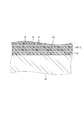
ここで、図4に示すように、プリプレグシート80の硬化処理前において、プリプレグシート80を構成する炭素繊維14同士の間隙に、プリプレグシート80を構成する樹脂15が含浸しているとともに、この樹脂15が金属メッシュ20を構成する金属線23同士の間隙にも含浸している。
また、金属メッシュ20の少なくとも最内周の金属線23は内型41に接している。
その後、プリプレグシート80を構成する樹脂15が硬化することによって、炭素繊維14と金属線23とが一体的となる。
また、金属メッシュ20の少なくとも最内周の金属線23は内型41に接しているため、その後に内型41が抜去されることで導波管100の内部空間30が形成された状態では、一部の金属線23は、樹脂15から露出した状態(内部空間30に露出した状態)となる。このため、電波が内部空間30を伝搬する際における反射率を十分に確保することができ、電波の良好な伝送効率を実現できる。
また、金属メッシュ20の少なくとも最内周の金属線23は内型41に接している。
その後、プリプレグシート80を構成する樹脂15が硬化することによって、炭素繊維14と金属線23とが一体的となる。
また、金属メッシュ20の少なくとも最内周の金属線23は内型41に接しているため、その後に内型41が抜去されることで導波管100の内部空間30が形成された状態では、一部の金属線23は、樹脂15から露出した状態(内部空間30に露出した状態)となる。このため、電波が内部空間30を伝搬する際における反射率を十分に確保することができ、電波の良好な伝送効率を実現できる。
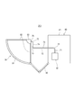
次に、図5を用いて本実施形態に係る導波システム200について説明する。
本実施形態の場合、導波システム200は、人工衛星である。ただし、本発明は、この例に限らず、導波システム200は、人工衛星以外の宇宙機器であってもよいし、地上で用いられるシステムであってもよい。
本実施形態の場合、導波システム200は、人工衛星である。ただし、本発明は、この例に限らず、導波システム200は、人工衛星以外の宇宙機器であってもよいし、地上で用いられるシステムであってもよい。
導波システム200は、例えば、アンテナ部50と、人工衛星本体60と、人工衛星本体60とアンテナ部50とを相互に連結しているブーム65と、を備えている。
アンテナ部50は、アンテナ鏡面51と、サポート部52を介してアンテナ鏡面51によって支持されているアンテナ給電部53と、を備えている。
人工衛星本体60は、構体61と、構体61に設けられている信号処理部62と、を備えている。
信号処理部62とアンテナ給電部53とは導波路70を介して相互に接続されている。このため、導波路70の内部空間を介して、アンテナ給電部53から信号処理部62へ電波を伝送することができる。
導波路70の少なくとも一部分が、上述した導波管100により構成されている。
アンテナ部50は、アンテナ鏡面51と、サポート部52を介してアンテナ鏡面51によって支持されているアンテナ給電部53と、を備えている。
人工衛星本体60は、構体61と、構体61に設けられている信号処理部62と、を備えている。
信号処理部62とアンテナ給電部53とは導波路70を介して相互に接続されている。このため、導波路70の内部空間を介して、アンテナ給電部53から信号処理部62へ電波を伝送することができる。
導波路70の少なくとも一部分が、上述した導波管100により構成されている。
このように、本実施形態に係る導波システム200は、アンテナ鏡面51と、アンテナ給電部53と、信号処理部62と、アンテナ給電部53と信号処理部62とを接続している導波路70と、を備え、本実施形態に係る導波管100が導波路70の少なくとも一部分を構成している。
〔第2実施形態〕
次に、図6及び図7を用いて第2実施形態を説明する。
本実施形態に係る導波管100も、管状の本体部10と、本体部10の内面に設けられた金属メッシュ20と、を備えて構成されている。すなわち、本実施形態の場合も、本体部10の管状部11の内面に金属メッシュ20が設けられている。
次に、図6及び図7を用いて第2実施形態を説明する。
本実施形態に係る導波管100も、管状の本体部10と、本体部10の内面に設けられた金属メッシュ20と、を備えて構成されている。すなわち、本実施形態の場合も、本体部10の管状部11の内面に金属メッシュ20が設けられている。
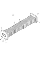
本実施形態の場合、本体部10は、屈曲可能な可撓性材料により蛇腹状に形成されている。すなわち、図6及び図7に示すように、本体部10の管状部11は、蛇腹状に形成されており、軸方向に伸縮可能となっているとともに、軸方向が屈曲する方向に屈曲可能となっている。
一方、金属メッシュ20は内腔断面積が略一定の管状に形成されている。
そして、本体部10の内周面と金属メッシュ20との接合部91(図7)が、本体部10の軸方向(管状部11の軸方向)において間欠的に配置されている。
このため、蛇腹状の本体部10(管状部11)の内周側に設けた金属メッシュ20の内周面の良好な平滑性を確保することができる。また、金属メッシュ20は管状部11の屈曲や伸縮に追従して伸縮することができる。よって、フレキシブル性を有し且つ電波の伝送効率が良好な導波管100を実現することができる。つまり、蛇腹状の本体部10の内面に金属メッシュ20が設けられていない場合と比べて、ロスの低減を図ることができる。
一方、金属メッシュ20は内腔断面積が略一定の管状に形成されている。
そして、本体部10の内周面と金属メッシュ20との接合部91(図7)が、本体部10の軸方向(管状部11の軸方向)において間欠的に配置されている。
このため、蛇腹状の本体部10(管状部11)の内周側に設けた金属メッシュ20の内周面の良好な平滑性を確保することができる。また、金属メッシュ20は管状部11の屈曲や伸縮に追従して伸縮することができる。よって、フレキシブル性を有し且つ電波の伝送効率が良好な導波管100を実現することができる。つまり、蛇腹状の本体部10の内面に金属メッシュ20が設けられていない場合と比べて、ロスの低減を図ることができる。
より詳細には、図7に示すように、本体部10は(本体部10の管状部11は)、内腔断面積が相対的に大きい大断面積部と内腔断面積が相対的に小さい小断面積部とを軸方向において交互に有し、接合部91は、本体部10の小断面積部の内周面と金属メッシュ20とを接合している。
ここで、管状に設けられた金属メッシュ20の内周面の良好な平滑性を実現するため、管状部11の軸方向において金属メッシュ20にテンションを付与した状態で、金属メッシュ20と管状部11とを接合部91において接合することが好ましい。
接合部91は、管状部11の周方向において連続的に形成されていてもよいし(すなわち連続的な周回状に形成されていてもよいし)、管状部11の周方向において間欠的に形成されていてもよい。
接合部91は、例えば、金属メッシュ20と管状部11の小断面積部の内周面との接触部に接着剤を塗布及び硬化させることによって形成されている。
接合部91は、例えば、金属メッシュ20と管状部11の小断面積部の内周面との接触部に接着剤を塗布及び硬化させることによって形成されている。
本実施形態の場合、本体部10の材料は、樹脂材料であってもよいし、アルミニウムなどの金属材料であってもよい。
本実施形態の場合も、金属メッシュ20の編組の仕方は、特に限定されない。
ただし、本実施形態の場合、金属メッシュ20は、管状部11の軸方向における伸縮性に優れたものであることが好ましい。
このため、一例として、金属メッシュ20は、当該金属メッシュ20の面内の直交二軸方向における一方の軸方向における伸縮率が他方の軸方向における伸縮率よりも大きくなる態様で編組されており、金属メッシュ20の一方の軸方向が本体部10の(管状部11の)軸方向AX1(図7)に沿って配置されている。
金属メッシュ20の面内の直交二軸方向における他方の軸方向は、軸方向AX1の軸周りの方向、すなわち管状部11の周方向に沿って配置されている。
このようにすることで、管状部11が軸方向に伸縮した場合に、金属メッシュ20も良好に追従して伸縮することができる。
ただし、本実施形態の場合、金属メッシュ20は、管状部11の軸方向における伸縮性に優れたものであることが好ましい。
このため、一例として、金属メッシュ20は、当該金属メッシュ20の面内の直交二軸方向における一方の軸方向における伸縮率が他方の軸方向における伸縮率よりも大きくなる態様で編組されており、金属メッシュ20の一方の軸方向が本体部10の(管状部11の)軸方向AX1(図7)に沿って配置されている。
金属メッシュ20の面内の直交二軸方向における他方の軸方向は、軸方向AX1の軸周りの方向、すなわち管状部11の周方向に沿って配置されている。
このようにすることで、管状部11が軸方向に伸縮した場合に、金属メッシュ20も良好に追従して伸縮することができる。
このような特性を有する金属メッシュ20の編組の仕方としては、トリコット編が好ましく、ダブルアトラス編がより好ましい。本実施形態では、金属メッシュ20は、ダブルアトラス編で編組されている。
ダブルアトラス編とは、トリコット編の一種であって、ダブルバンダイク編とも称される編み方である。ダブルアトラス編では、二枚おさのたて糸で、互いに反対方向にシングルアトラス編が行われることによって、二重組織が形成される。つまり、ダブルアトラス編では、シングルアトラス編を二重に重ねた組織が得られる。シングルアトラス編とは、バンダイク編とも称される経編の一種であり、ジグザグ状(千鳥状)の編目が形成される編み方である。シングルアトラス編は、一種の振り編みであり、たて糸をコースごとに右と左に数回ずつ移行させることを繰り返して行われる。
ダブルアトラス編とは、トリコット編の一種であって、ダブルバンダイク編とも称される編み方である。ダブルアトラス編では、二枚おさのたて糸で、互いに反対方向にシングルアトラス編が行われることによって、二重組織が形成される。つまり、ダブルアトラス編では、シングルアトラス編を二重に重ねた組織が得られる。シングルアトラス編とは、バンダイク編とも称される経編の一種であり、ジグザグ状(千鳥状)の編目が形成される編み方である。シングルアトラス編は、一種の振り編みであり、たて糸をコースごとに右と左に数回ずつ移行させることを繰り返して行われる。
本実施形態の場合、管状に設けられた金属メッシュ20の外周面に沿って、樹脂などの可撓性の材料により構成されたベースシートが管状に設けられていてもよい。この場合、ベースシートと管状部11とが接合部91において接合され、金属メッシュ20と管状部11とは、ベースシートを介して相互に接合される。
ここで、図5に示す導波システム200の導波路70の少なくとも一部分が、本実施形態に係る導波管100、すなわちフレキシブル性を有する導波管100で構成されていることによって、アンテナ部50と人工衛星本体60との相対的な位置の変化や振動を当該導波管100が吸収することができる。
より詳細には、図5の導波路70は、例えば、それぞれ直線状に形成されている複数の直線部(例えば、第1直線部71、第2直線部73、第3直線部74及び第4直線部75)と、これら直線部同士を接続している屈曲部72と、を備えている。
複数の直線部のうち、第2直線部73は、最も長く、アンテナ部50側から人工衛星本体60側に向けて延びている。第1直線部71及び第3直線部74は、それぞれ第2直線部73に対して交差(例えば直交)している。第4直線部75は、例えば、第3直線部74に対して直交しており、第2直線部73に対して平行に延在している。
本実施形態に係る導波管100、すなわちフレキシブル性を有する導波管100は、典型的には、第1直線部71の少なくとも一部分と、第3直線部74の少なくとも一部分と、をそれぞれ構成していることが好ましい。第2直線部73がリジッドな導波管(例えば第1実施形態に係る導波管100)である場合に、当該リジッドな導波管が熱膨張又は熱収縮するときに、第1直線部71と第3直線部74を構成するフレキシブルな導波管100が屈曲することで、導波路70に生じる歪みを吸収することができる。
このように、一例として、導波路70を構成する複数の直線部のうち最も長い直線部である最長直線部(第2直線部73)をリジッドな導波管により構成し、当該最長直線部に隣接していて当該最長直線部に対して交差する方向に延在する直線部である隣接直線部(第1直線部71、第3直線部74)の少なくとも一方、好ましくは両方の一部分を、フレキシブルな導波管100により構成することが好ましい。
ただし、本実施形態に係る導波管100は、屈曲部72を構成するのに用いられてもよいし、その他の直線部(第2直線部73、第4直線部75)を構成するのに用いられてもよい。
より詳細には、図5の導波路70は、例えば、それぞれ直線状に形成されている複数の直線部(例えば、第1直線部71、第2直線部73、第3直線部74及び第4直線部75)と、これら直線部同士を接続している屈曲部72と、を備えている。
複数の直線部のうち、第2直線部73は、最も長く、アンテナ部50側から人工衛星本体60側に向けて延びている。第1直線部71及び第3直線部74は、それぞれ第2直線部73に対して交差(例えば直交)している。第4直線部75は、例えば、第3直線部74に対して直交しており、第2直線部73に対して平行に延在している。
本実施形態に係る導波管100、すなわちフレキシブル性を有する導波管100は、典型的には、第1直線部71の少なくとも一部分と、第3直線部74の少なくとも一部分と、をそれぞれ構成していることが好ましい。第2直線部73がリジッドな導波管(例えば第1実施形態に係る導波管100)である場合に、当該リジッドな導波管が熱膨張又は熱収縮するときに、第1直線部71と第3直線部74を構成するフレキシブルな導波管100が屈曲することで、導波路70に生じる歪みを吸収することができる。
このように、一例として、導波路70を構成する複数の直線部のうち最も長い直線部である最長直線部(第2直線部73)をリジッドな導波管により構成し、当該最長直線部に隣接していて当該最長直線部に対して交差する方向に延在する直線部である隣接直線部(第1直線部71、第3直線部74)の少なくとも一方、好ましくは両方の一部分を、フレキシブルな導波管100により構成することが好ましい。
ただし、本実施形態に係る導波管100は、屈曲部72を構成するのに用いられてもよいし、その他の直線部(第2直線部73、第4直線部75)を構成するのに用いられてもよい。
本発明は上述の各実施形態に限定されるものではなく、本発明の目的が達成される限りにおける種々の変形、改良等の態様も含む。
また、上記の実施形態は、相反しない範囲で組み合わせることができる。
また、導波管100の各種の構成要素は、個々に独立した存在である必要はなく、複数の構成要素が一個の部材として形成されていること、一つの構成要素が複数の部材で形成されていること、ある構成要素が他の構成要素の一部であること、ある構成要素の一部と他の構成要素の一部とが重複していること、等を許容する。
また、上記の実施形態は、相反しない範囲で組み合わせることができる。
また、導波管100の各種の構成要素は、個々に独立した存在である必要はなく、複数の構成要素が一個の部材として形成されていること、一つの構成要素が複数の部材で形成されていること、ある構成要素が他の構成要素の一部であること、ある構成要素の一部と他の構成要素の一部とが重複していること、等を許容する。
本実施形態は以下の技術思想を包含する。
(1)管状の本体部と、前記本体部の内面に設けられた金属メッシュと、を備える導波管。
(2)前記本体部は樹脂材料を含んで構成されている(1)に記載の導波管。
(3)前記本体部を構成する樹脂材料が前記金属メッシュに含浸している(2)に記載の導波管。
(4)前記本体部は、屈曲可能な可撓性材料により蛇腹状に形成されており、
前記金属メッシュは内腔断面積が略一定の管状に形成されており、
前記本体部の内周面と前記金属メッシュとの接合部が、前記本体部の軸方向において間欠的に配置されている(1)又は(2)に記載の導波管。
(5)前記本体部は、内腔断面積が相対的に大きい大断面積部と内腔断面積が相対的に小さい小断面積部とを軸方向において交互に有し、
前記接合部は、前記本体部の前記小断面積部の内周面と前記金属メッシュとを接合している(4)に記載の導波管。
(6)前記金属メッシュは、面内の直交二軸方向における一方の軸方向における伸縮率が他方の軸方向における伸縮率よりも大きくなる態様で編組されており、
前記金属メッシュの前記一方の軸方向が本体部の軸方向に沿って配置されている(4)又は(5)に記載の導波管。
(7)前記金属メッシュはダブルアトラス編で編組されている(6)に記載の導波管。
(8)アンテナ鏡面と、アンテナ給電部と、信号処理部と、前記アンテナ給電部と前記信号処理部とを接続している導波路と、を備え、
(1)から(7)のいずれか一項に記載の導波管が前記導波路の少なくとも一部分を構成している導波システム。
(1)管状の本体部と、前記本体部の内面に設けられた金属メッシュと、を備える導波管。
(2)前記本体部は樹脂材料を含んで構成されている(1)に記載の導波管。
(3)前記本体部を構成する樹脂材料が前記金属メッシュに含浸している(2)に記載の導波管。
(4)前記本体部は、屈曲可能な可撓性材料により蛇腹状に形成されており、
前記金属メッシュは内腔断面積が略一定の管状に形成されており、
前記本体部の内周面と前記金属メッシュとの接合部が、前記本体部の軸方向において間欠的に配置されている(1)又は(2)に記載の導波管。
(5)前記本体部は、内腔断面積が相対的に大きい大断面積部と内腔断面積が相対的に小さい小断面積部とを軸方向において交互に有し、
前記接合部は、前記本体部の前記小断面積部の内周面と前記金属メッシュとを接合している(4)に記載の導波管。
(6)前記金属メッシュは、面内の直交二軸方向における一方の軸方向における伸縮率が他方の軸方向における伸縮率よりも大きくなる態様で編組されており、
前記金属メッシュの前記一方の軸方向が本体部の軸方向に沿って配置されている(4)又は(5)に記載の導波管。
(7)前記金属メッシュはダブルアトラス編で編組されている(6)に記載の導波管。
(8)アンテナ鏡面と、アンテナ給電部と、信号処理部と、前記アンテナ給電部と前記信号処理部とを接続している導波路と、を備え、
(1)から(7)のいずれか一項に記載の導波管が前記導波路の少なくとも一部分を構成している導波システム。
この出願は、2019年3月6日に出願された日本出願特願2019-40737号を基礎とする優先権を主張し、その開示の総てをここに取り込む。
10 本体部
11 管状部
12 フランジ部
13 止着孔
14 炭素繊維
15 樹脂
20 金属メッシュ
20a 長辺
20b 短辺
21 始端
22 終端
23 金属線
30 内部空間
41 内型
42 外型
50 アンテナ部
51 アンテナ鏡面
52 サポート部
53 アンテナ給電部
60 人工衛星本体
61 構体
62 信号処理部
65 ブーム
70 導波路
71 第1直線部
72 屈曲部
73 第2直線部
74 第3直線部
75 第4直線部
80 プリプレグシート
91 接合部
100 導波管
200 導波システム
11 管状部
12 フランジ部
13 止着孔
14 炭素繊維
15 樹脂
20 金属メッシュ
20a 長辺
20b 短辺
21 始端
22 終端
23 金属線
30 内部空間
41 内型
42 外型
50 アンテナ部
51 アンテナ鏡面
52 サポート部
53 アンテナ給電部
60 人工衛星本体
61 構体
62 信号処理部
65 ブーム
70 導波路
71 第1直線部
72 屈曲部
73 第2直線部
74 第3直線部
75 第4直線部
80 プリプレグシート
91 接合部
100 導波管
200 導波システム
Claims (8)
- 管状の本体部と、前記本体部の内面に設けられた金属メッシュと、を備える導波管。
- 前記本体部は樹脂材料を含んで構成されている請求項1に記載の導波管。
- 前記本体部を構成する樹脂材料が前記金属メッシュに含浸している請求項2に記載の導波管。
- 前記本体部は、屈曲可能な可撓性材料により蛇腹状に形成されており、
前記金属メッシュは内腔断面積が略一定の管状に形成されており、
前記本体部の内周面と前記金属メッシュとの接合部が、前記本体部の軸方向において間欠的に配置されている請求項1又は2に記載の導波管。 - 前記本体部は、内腔断面積が相対的に大きい大断面積部と内腔断面積が相対的に小さい小断面積部とを軸方向において交互に有し、
前記接合部は、前記本体部の前記小断面積部の内周面と前記金属メッシュとを接合している請求項4に記載の導波管。 - 前記金属メッシュは、面内の直交二軸方向における一方の軸方向における伸縮率が他方の軸方向における伸縮率よりも大きくなる態様で編組されており、
前記金属メッシュの前記一方の軸方向が本体部の軸方向に沿って配置されている請求項4又は5に記載の導波管。 - 前記金属メッシュはダブルアトラス編で編組されている請求項6に記載の導波管。
- アンテナ鏡面と、アンテナ給電部と、信号処理部と、前記アンテナ給電部と前記信号処理部とを接続している導波路と、を備え、
請求項1から7のいずれか一項に記載の導波管が前記導波路の少なくとも一部分を構成している導波システム。
Applications Claiming Priority (2)
| Application Number | Priority Date | Filing Date | Title |
|---|---|---|---|
| JP2019-040737 | 2019-03-06 | ||
| JP2019040737A JP7202568B2 (ja) | 2019-03-06 | 2019-03-06 | 導波管及び導波システム |
Publications (1)
| Publication Number | Publication Date |
|---|---|
| WO2020179888A1 true WO2020179888A1 (ja) | 2020-09-10 |
Family
ID=72337173
Family Applications (1)
| Application Number | Title | Priority Date | Filing Date |
|---|---|---|---|
| PCT/JP2020/009523 Ceased WO2020179888A1 (ja) | 2019-03-06 | 2020-03-05 | 導波管及び導波システム |
Country Status (2)
| Country | Link |
|---|---|
| JP (1) | JP7202568B2 (ja) |
| WO (1) | WO2020179888A1 (ja) |
Cited By (1)
| Publication number | Priority date | Publication date | Assignee | Title |
|---|---|---|---|---|
| RU204491U1 (ru) * | 2021-02-10 | 2021-05-27 | Федеральное государственное бюджетное образовательное учреждение высшего образования "Волгоградский государственный технический университет" (ВолгГТУ) | Волноводный датчик импульсных давлений |
Citations (4)
| Publication number | Priority date | Publication date | Assignee | Title |
|---|---|---|---|---|
| US4323867A (en) * | 1980-08-27 | 1982-04-06 | The United States Of America As Represented By The Secretary Of The Navy | Fragment-tolerant transmission line |
| JP2002076755A (ja) * | 2000-08-28 | 2002-03-15 | Nec Eng Ltd | ガイドホーン又は導波管などの立体的導波構造 |
| JP2003143051A (ja) * | 2001-08-28 | 2003-05-16 | Trw Inc | 衛星用の反射鏡アンテナ・システム |
| WO2014188218A1 (en) * | 2013-05-24 | 2014-11-27 | Ems Waves Limited | A microwave guide |
-
2019
- 2019-03-06 JP JP2019040737A patent/JP7202568B2/ja active Active
-
2020
- 2020-03-05 WO PCT/JP2020/009523 patent/WO2020179888A1/ja not_active Ceased
Patent Citations (4)
| Publication number | Priority date | Publication date | Assignee | Title |
|---|---|---|---|---|
| US4323867A (en) * | 1980-08-27 | 1982-04-06 | The United States Of America As Represented By The Secretary Of The Navy | Fragment-tolerant transmission line |
| JP2002076755A (ja) * | 2000-08-28 | 2002-03-15 | Nec Eng Ltd | ガイドホーン又は導波管などの立体的導波構造 |
| JP2003143051A (ja) * | 2001-08-28 | 2003-05-16 | Trw Inc | 衛星用の反射鏡アンテナ・システム |
| WO2014188218A1 (en) * | 2013-05-24 | 2014-11-27 | Ems Waves Limited | A microwave guide |
Cited By (1)
| Publication number | Priority date | Publication date | Assignee | Title |
|---|---|---|---|---|
| RU204491U1 (ru) * | 2021-02-10 | 2021-05-27 | Федеральное государственное бюджетное образовательное учреждение высшего образования "Волгоградский государственный технический университет" (ВолгГТУ) | Волноводный датчик импульсных давлений |
Also Published As
| Publication number | Publication date |
|---|---|
| JP2020145588A (ja) | 2020-09-10 |
| JP7202568B2 (ja) | 2023-01-12 |
Similar Documents
| Publication | Publication Date | Title |
|---|---|---|
| US5328742A (en) | Rod and method of manufacturing same | |
| US10208410B2 (en) | Braided textile sleeve with axially collapsible, anti-kinking feature and method of construction thereof | |
| JP5463414B2 (ja) | 構造要素及び構造要素を製造するための方法 | |
| JP2014015183A (ja) | 伸展構造物 | |
| CN114375353B (zh) | 波纹编织套筒及其制造方法 | |
| WO2020179888A1 (ja) | 導波管及び導波システム | |
| GB2289928A (en) | Connecting fibre composite rods end-to-end | |
| JP6547686B2 (ja) | ワイヤーハーネス | |
| JP6373196B2 (ja) | 光ファイバケーブル | |
| US9657871B2 (en) | High pressure hose | |
| RU2560194C2 (ru) | Композитная конструктивная панель задней кромки элемента летательного аппарата | |
| JP2000178855A (ja) | 空隙部充填用繊維構造体 | |
| CN107923082A (zh) | 纤维结构体和纤维增强复合材料 | |
| KR102231321B1 (ko) | 복합재 로드 및 이의 제조방법 | |
| JPS62117845A (ja) | 丸織布とこれを組合わせたホ−ス | |
| JP7708977B2 (ja) | カバーステントの製造方法およびカバーステント | |
| KR20180091006A (ko) | 편조된 반사성 직물 슬리브 및 그의 구성 방법 | |
| JP7547012B2 (ja) | ワイヤハーネス製造方法 | |
| RU2019131583A (ru) | Четырехточечный рычаг подвески и способ изготовления четырехточечного рычага подвески | |
| JP6711624B2 (ja) | 釣竿用ブランク及びその製法 | |
| JP2022180320A (ja) | 高アスペクト比強度ロッドを有する光ケーブル | |
| JP3515891B2 (ja) | 釣 竿 | |
| JP7280217B2 (ja) | コルゲートチューブの固定構造およびコルゲートチューブの固定方法 | |
| CN116526111B (zh) | 一种适用于天线设备的伸缩式鱼骨信号发射线 | |
| JP2022127276A (ja) | 電線用外装部材、ワイヤハーネスおよびワイヤハーネスの配索構造 |
Legal Events
| Date | Code | Title | Description |
|---|---|---|---|
| 121 | Ep: the epo has been informed by wipo that ep was designated in this application |
Ref document number: 20765749 Country of ref document: EP Kind code of ref document: A1 |
|
| NENP | Non-entry into the national phase |
Ref country code: DE |
|
| 122 | Ep: pct application non-entry in european phase |
Ref document number: 20765749 Country of ref document: EP Kind code of ref document: A1 |