WO2020179706A1 - 通信制御装置および通信システム - Google Patents
通信制御装置および通信システム Download PDFInfo
- Publication number
- WO2020179706A1 WO2020179706A1 PCT/JP2020/008464 JP2020008464W WO2020179706A1 WO 2020179706 A1 WO2020179706 A1 WO 2020179706A1 JP 2020008464 W JP2020008464 W JP 2020008464W WO 2020179706 A1 WO2020179706 A1 WO 2020179706A1
- Authority
- WO
- WIPO (PCT)
- Prior art keywords
- communication
- communication control
- control device
- communication system
- network
- Prior art date
- Legal status (The legal status is an assumption and is not a legal conclusion. Google has not performed a legal analysis and makes no representation as to the accuracy of the status listed.)
- Ceased
Links
Images


Classifications
-
- H—ELECTRICITY
- H04—ELECTRIC COMMUNICATION TECHNIQUE
- H04L—TRANSMISSION OF DIGITAL INFORMATION, e.g. TELEGRAPHIC COMMUNICATION
- H04L9/00—Cryptographic mechanisms or cryptographic arrangements for secret or secure communications; Network security protocols
- H04L9/32—Cryptographic mechanisms or cryptographic arrangements for secret or secure communications; Network security protocols including means for verifying the identity or authority of a user of the system or for message authentication, e.g. authorization, entity authentication, data integrity or data verification, non-repudiation, key authentication or verification of credentials
- H04L9/3271—Cryptographic mechanisms or cryptographic arrangements for secret or secure communications; Network security protocols including means for verifying the identity or authority of a user of the system or for message authentication, e.g. authorization, entity authentication, data integrity or data verification, non-repudiation, key authentication or verification of credentials using challenge-response
- H04L9/3273—Cryptographic mechanisms or cryptographic arrangements for secret or secure communications; Network security protocols including means for verifying the identity or authority of a user of the system or for message authentication, e.g. authorization, entity authentication, data integrity or data verification, non-repudiation, key authentication or verification of credentials using challenge-response for mutual authentication
-
- G—PHYSICS
- G06—COMPUTING OR CALCULATING; COUNTING
- G06F—ELECTRIC DIGITAL DATA PROCESSING
- G06F21/00—Security arrangements for protecting computers, components thereof, programs or data against unauthorised activity
- G06F21/30—Authentication, i.e. establishing the identity or authorisation of security principals
- G06F21/44—Program or device authentication
- G06F21/445—Program or device authentication by mutual authentication, e.g. between devices or programs
-
- H—ELECTRICITY
- H04—ELECTRIC COMMUNICATION TECHNIQUE
- H04L—TRANSMISSION OF DIGITAL INFORMATION, e.g. TELEGRAPHIC COMMUNICATION
- H04L63/00—Network architectures or network communication protocols for network security
- H04L63/04—Network architectures or network communication protocols for network security for providing a confidential data exchange among entities communicating through data packet networks
- H04L63/0428—Network architectures or network communication protocols for network security for providing a confidential data exchange among entities communicating through data packet networks wherein the data content is protected, e.g. by encrypting or encapsulating the payload
-
- H—ELECTRICITY
- H04—ELECTRIC COMMUNICATION TECHNIQUE
- H04L—TRANSMISSION OF DIGITAL INFORMATION, e.g. TELEGRAPHIC COMMUNICATION
- H04L63/00—Network architectures or network communication protocols for network security
- H04L63/08—Network architectures or network communication protocols for network security for authentication of entities
- H04L63/0823—Network architectures or network communication protocols for network security for authentication of entities using certificates
-
- H—ELECTRICITY
- H04—ELECTRIC COMMUNICATION TECHNIQUE
- H04L—TRANSMISSION OF DIGITAL INFORMATION, e.g. TELEGRAPHIC COMMUNICATION
- H04L63/00—Network architectures or network communication protocols for network security
- H04L63/08—Network architectures or network communication protocols for network security for authentication of entities
- H04L63/083—Network architectures or network communication protocols for network security for authentication of entities using passwords
-
- H—ELECTRICITY
- H04—ELECTRIC COMMUNICATION TECHNIQUE
- H04L—TRANSMISSION OF DIGITAL INFORMATION, e.g. TELEGRAPHIC COMMUNICATION
- H04L63/00—Network architectures or network communication protocols for network security
- H04L63/08—Network architectures or network communication protocols for network security for authentication of entities
- H04L63/0869—Network architectures or network communication protocols for network security for authentication of entities for achieving mutual authentication
-
- H—ELECTRICITY
- H04—ELECTRIC COMMUNICATION TECHNIQUE
- H04L—TRANSMISSION OF DIGITAL INFORMATION, e.g. TELEGRAPHIC COMMUNICATION
- H04L63/00—Network architectures or network communication protocols for network security
- H04L63/08—Network architectures or network communication protocols for network security for authentication of entities
- H04L63/0892—Network architectures or network communication protocols for network security for authentication of entities by using authentication-authorization-accounting [AAA] servers or protocols
-
- H—ELECTRICITY
- H04—ELECTRIC COMMUNICATION TECHNIQUE
- H04L—TRANSMISSION OF DIGITAL INFORMATION, e.g. TELEGRAPHIC COMMUNICATION
- H04L63/00—Network architectures or network communication protocols for network security
- H04L63/16—Implementing security features at a particular protocol layer
- H04L63/168—Implementing security features at a particular protocol layer above the transport layer
-
- H—ELECTRICITY
- H04—ELECTRIC COMMUNICATION TECHNIQUE
- H04L—TRANSMISSION OF DIGITAL INFORMATION, e.g. TELEGRAPHIC COMMUNICATION
- H04L9/00—Cryptographic mechanisms or cryptographic arrangements for secret or secure communications; Network security protocols
- H04L9/08—Key distribution or management, e.g. generation, sharing or updating, of cryptographic keys or passwords
- H04L9/0894—Escrow, recovery or storing of secret information, e.g. secret key escrow or cryptographic key storage
- H04L9/0897—Escrow, recovery or storing of secret information, e.g. secret key escrow or cryptographic key storage involving additional devices, e.g. trusted platform module [TPM], smartcard or USB
-
- H—ELECTRICITY
- H04—ELECTRIC COMMUNICATION TECHNIQUE
- H04L—TRANSMISSION OF DIGITAL INFORMATION, e.g. TELEGRAPHIC COMMUNICATION
- H04L9/00—Cryptographic mechanisms or cryptographic arrangements for secret or secure communications; Network security protocols
- H04L9/32—Cryptographic mechanisms or cryptographic arrangements for secret or secure communications; Network security protocols including means for verifying the identity or authority of a user of the system or for message authentication, e.g. authorization, entity authentication, data integrity or data verification, non-repudiation, key authentication or verification of credentials
- H04L9/3263—Cryptographic mechanisms or cryptographic arrangements for secret or secure communications; Network security protocols including means for verifying the identity or authority of a user of the system or for message authentication, e.g. authorization, entity authentication, data integrity or data verification, non-repudiation, key authentication or verification of credentials involving certificates, e.g. public key certificate [PKC] or attribute certificate [AC]; Public key infrastructure [PKI] arrangements
Definitions
- An embodiment of the present invention relates to a communication control device and a communication system.
- the communication system needs to protect the data it handles and the control information of the device from attacks such as malware.
- devices such as surveillance cameras installed as social infrastructure need to ensure the safety of data to be communicated.
- it is difficult to replace each device that builds social infrastructure, such as a surveillance camera, frequently, so there is a problem that safety measures become insufficient.
- An object to be solved by the present invention is to provide a communication control device and a communication system capable of improving the security of communication used in a social infrastructure system or the like.
- the communication control device includes a first communication system connected between the first device and the network communication network, and a first device and a network communication network separately from the first communication system. And a second communication system connected between the two.
- the first communication system and the second communication system have a controller.
- the controller is determined by mutual authentication processing between the private key issued by the private authentication authority and the second communication control device connected between the network communication network and the second device using the client certificate.
- Information transmitted from the first device to the second device is encrypted by using the common key to transmit to the second communication control device, and the information is transmitted from the second device to the first device. Communication is performed in the first communication mode in which the decrypted information is transmitted to the first device.
- the controller when one of the communication systems executes communication in the first communication mode and a defect is detected in the communication system executing the communication in the first communication mode, the other communication system becomes the first.
- the communication mode is switched to the communication mode 1.
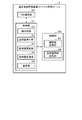
- FIG. 1 is a diagram illustrating a basic configuration example of a communication system according to each embodiment.
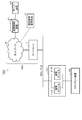
- FIG. 2 is a block diagram showing a functional configuration example of the client device and the server device according to each embodiment.
- FIG. 3 is a block diagram showing a functional configuration example of the communication control device on the client side and the communication control device on the server side according to each embodiment.
- FIG. 4 is a diagram showing a hardware configuration example of an IC card as a configuration example of an authentication unit in the communication control device according to each embodiment.
- FIG. 5 is a block diagram showing a functional configuration example of a C card as a configuration example of an authentication unit in the communication control device according to each embodiment.
- FIG. 6 is a block diagram showing a functional configuration example in the communication control management device according to each embodiment.
- FIG. 1 is a diagram illustrating a basic configuration example of a communication system according to each embodiment.
- FIG. 2 is a block diagram showing a functional configuration example of the client device and the server device according to each embodiment.
- FIG. 7 is a sequence showing an example of processing performed by the communication system shown in FIG.
- FIG. 8 is a diagram showing a first configuration example of the communication system according to the first embodiment.
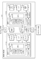
- FIG. 9 is a block diagram showing a configuration example of the communication control device in the first configuration example of the communication system according to the first embodiment.
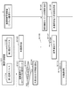
- FIG. 10 is a sequence for explaining an operation example of the communication system according to the first configuration example of the first embodiment.
- FIG. 11 is a diagram illustrating a second configuration example of the communication system according to the first embodiment.
- FIG. 12 is a block diagram showing a configuration example of a communication control device in a second configuration example of the communication system according to the first embodiment.
- FIG. 13 is a sequence for explaining an operation example of the communication system according to the second configuration example of the first embodiment.
- FIG. 14 is a diagram illustrating a configuration example of a communication system according to the second embodiment.
- FIG. 15 is a block diagram showing a configuration example of the communication control device in the configuration example of the communication system according to the second embodiment.
- FIG. 16 is a flowchart for explaining an operation example of the distributed controller in the communication system according to the second embodiment.
- FIG. 17 is a block diagram showing a configuration example of a communication system according to the third embodiment.
- FIG. 18 is a sequence for explaining a first operation example of the communication system according to the third embodiment.
- FIG. 19 is a sequence for explaining the second operation example of the communication system according to the third embodiment.
- FIG. 20 is a sequence for explaining the first operation example of the communication system according to the fourth embodiment.
- FIG. 21 is a sequence for explaining the second operation example of the communication system according to the fourth embodiment.
- FIG. 22 is a sequence for explaining the third operation example of the communication system according to the fourth embodiment.
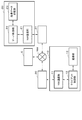
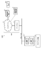
- FIG. 1 is a diagram showing a configuration example of a communication system 1 having a configuration that is a base of the communication system according to each embodiment.
- the communication system 1 includes a client device 10 (10-1 to 10-N), a server device 20, and a communication control device 30 (30-1 to 30-N) on the client side (“first communication control device”).
- first communication control device An example
- server-side communication control device 31 an example of a “first communication control device”
- a communication control management device 5 an example of a “private certificate authority”
- network 6 and the gateway 7 that connects the network 6 to the client device 10 and the like are collectively referred to as “network NW”.
- the client device 10 connects to the network NW via the communication control device 30 on the client side.
- the server device 20 connects to the network NW via the communication control device 31 on the server side. The details of the configurations of the client device 10 and the server device 20 will be described later.
- the communication control device 30 on the client side is connected between the client device 10 and the network NW, and mediates communication between the client device 10 and the server device 20.
- the communication control device 30 on the client side acquires data transmitted to the server device 20 by the client device 10, and outputs the acquired data to the server device 20.
- the communication control device 30 on the client side transmits data to the server device 20
- the data acquired from the client device 10 is encrypted, and the encrypted data is transmitted to the server device 20.
- the communication control device 30 on the client side acquires data transmitted to the client device 10 by the server device 20, and outputs the acquired data to the client device 10.
- the data acquired by the communication control device 30 on the client side is encrypted data.
- the communication control device 30 on the client side outputs data to the client device 10, it decodes the data acquired from the server device 20 via the communication control device 31 on the server side, and outputs the decoded data to the client device 10. To do.
- the communication control device 31 on the server side is connected between the server device 20 and the network NW, and mediates communication between the client device 10 and the server device 20.
- the communication control device 31 on the server side acquires data transmitted to the client device 10 by the server device 20, and transmits the acquired data to the client device 10.
- the communication control device 31 on the server side transmits data to the client device 10
- the data acquired from the server device 20 is encrypted, and the encrypted data is transmitted to the client device 10.
- the communication control device 31 on the server side acquires the data transmitted to the server device 20 by the client device 10, and outputs the acquired data to the server device 20.
- the data acquired by the communication control device 31 on the server side is encrypted data.
- the communication control device 31 on the server side outputs data to the server device 20, it decodes the data acquired from the client device 10 via the communication control device 30 on the client side, and outputs the decoded data to the server device 20. To do.
- Data encryption performed by the communication control device 30 on the client side and the communication control device 31 on the server side is performed by, for example, the SSL (Secure Socket Layer)/TLS (Transport Layer Security) protocol.
- the communication control device 30 on the client side and the communication control device 31 on the server side for example, by combining the SSL/TLS protocol with HTTP, encrypts the data included in the HTTP to improve security (HTTPS Secure). ).
- the data encryption performed by the communication control device 30 on the client side and the communication control device 31 on the server side is not limited to HTTP being HTTPS.
- the client-side communication control device 30 and the server-side communication control device 31 may be replaced with a secure communication protocol with improved safety by combining the SSL/TLS protocol with various communication protocols.
- the communication control device 30 on the client side and the communication control device 31 on the server side may replace FTP (File Transfer Protocol) with FTPS (FTP Secure).
- data encrypted by the communication control device 30 on the client side or the communication control device 31 on the server side is output to the network NW.
- the data flowing through the network NW in the communication system 1 is encrypted data. Therefore, the risk that the data transmitted / received on the network NW is maliciously accessed from the outside and the data is eavesdropped is avoided, and the safety is improved.
- the data eavesdropping referred to here means an "act of eavesdropping on data" or an "act of extracting data”.
- the communication control management device 5 is a communication management server for managing communication using the communication control device on the client side and the communication control device on the server side. For example, the communication control management device 5 issues a client certificate and a private key to the communication control device 30 on the client side. In the configuration example shown in FIG. 1, the communication control management device 5 issues a client certificate and a private key stored in an IC card mounted on the communication control device 30 on the client side. Further, the communication control management device 5 transmits the client certificate to be stored in the IC card and the private key to the communication control device 30 on the client side in which the IC card is mounted via the network NW.
- the communication control management device 5 issues a server certificate and a private key to the communication control device 31 on the server side.
- the communication control management device 5 issues a server certificate and a private key stored in the IC card.
- the communication control management device 5 transmits the server certificate and the private key stored in the IC card to the communication control device 31 on the server side in which the IC card is mounted via the network NW.
- the client certificate, the server certificate, and the private key are used to determine a common key (session key) used when the client-side communication control device 30 and the server-side communication control device 31 perform encrypted communication. It is necessary information for.
- the client device 10 and the server device 20 are components (components) that construct a social infrastructure system, for example.
- Social infrastructure is equipment necessary for preparing social infrastructure such as road transportation network, power generation equipment, distribution power equipment, water treatment equipment, gas distribution equipment, and the like.
- the social infrastructure system is, for example, a mechanism for stably operating the social infrastructure by monitoring the social infrastructure, grasping changes in the situation, and responding to the changes.
- the client device 10 and the server device are components of a monitoring system that monitors roads and public facilities will be described as an example.
- the client device 10 is a device (network monitoring camera) that transmits the imaged data in which the road condition and the like are imaged through the network NW.
- the server device 20 is a device that receives the imaging data transmitted by the client device 10 via the network NW.
- the client device 10 and the server device 20 are not limited to the components of the monitoring system.
- the client device 10 and the server device may be components of a system that monitors the power status of power generation equipment or delivery power equipment, a system that acquires the delivery status at a distribution center, or equipment at a factory or research institute. It may be a component such as a system for acquiring the operating status of.
- FIG. 2 is a block diagram showing a functional configuration example of the client device 10 and the server device 20 shown in FIG.
- the client device 10 includes a NW (network) communication unit 11, a client control unit 12, and an imaging unit 13.
- the NW communication unit 11 is, for example, an Ethernet (registered trademark) port of the client device 10.
- the NW communication unit 11 is connected to the communication control device 30 on the client side, and outputs the data transmitted from the client device 10 to the server device 20 to the communication control device 30 on the client side.
- the NW communication unit 11 corresponds to a functional unit that is connected to the network NW and communicates with the server device 20 via the network NW in a conventional system.
- the client control unit 12 is, for example, a processor including a CPU and the like, and controls the client device 10 in an integrated manner.
- the client control unit 12 causes the imaging unit 13 to start or stop imaging according to the control from the server device 20, and sets imaging conditions such as the direction of the camera to be imaged with respect to the imaging unit 13 and the magnification at the time of imaging. Set it.
- the imaging unit 13 captures a landscape at a predetermined location according to the instructions of the client control unit 12.
- the imaging unit 13 outputs the captured data (imaging data) to the client control unit 12.
- the server device 20 includes an NW (network) communication unit 21, a server control unit 22, and an imaging data storage unit 23.
- the NW communication unit 21 is, for example, an Ethernet (registered trademark) port of the server device 20.
- the NW communication unit 21 is connected to the server-side communication control device 31 and outputs the data transmitted from the server device 20 to the client device 10 to the server-side communication control device 31. If it is a conventional system, the NW communication unit 21 corresponds to a functional unit that is connected to the network NW and communicates with the client device 10 via the network NW.
- the server control unit 22 is, for example, a processor including a CPU and controls the server device 20 in a centralized manner.
- the server control unit 22 stores, for example, the imaged data captured by the client device 10 in the imaged data storage unit 23.
- the imaging data storage unit 23 stores the imaging data according to the instruction of the server control unit 22.
- the unencrypted information (so-called plaintext) output to the network NW by the client device 10 or the server device 20 flows through the network NW.
- the client device 10 encrypts the imaged data and outputs it to the network NW.
- the client control unit 12 of the client device 10 encrypts the imaging data and outputs the encrypted imaging data to the network NW.
- a processor such as a CPU provided in a surveillance camera is generally used for the purpose of compressing or encoding image data, it is further subjected to processing for encryption. In many cases, it does not have just the resources. In such a case, the CPU originally possessed by the client control unit 12 cannot encrypt the captured data.
- the client control unit 12 encrypts the imaging data, it is necessary to change or replace the hardware configuration of the client control unit 12, such as mounting a processor for encrypting the imaging data on the client control unit 12. It is possible that Since the client device 10 is a component that constitutes social infrastructure such as a surveillance camera, it is not easy to change or replace the hardware configuration. In view of such circumstances, it is desirable that the imaged data is encrypted and output to the network NW without changing the client device 10.
- the communication control device 30 on the client side connected between the client device 10 and the network NW encrypts the data transmitted by the client device 10 and outputs the data to the network NW.
- the server-side communication control device 31 connected between the server device 20 and the network NW encrypts the control data transmitted by the server device 20 and outputs the encrypted control data to the network NW.
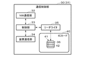
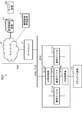
- FIG. 3 is a block diagram showing a functional configuration example of the communication control device 30 on the client side and the communication control device 31 on the server side shown in FIG.
- the functional configurations of the communication control device 30 on the client side and the communication control device 31 on the server side are the same. Therefore, in the following, the configuration of one (for example, the communication control device 30 on the client side) will be described, and the configuration of the other (for example, the communication control device 31 on the server side) will be omitted. Further, in the following, when the communication control device 30 on the client side and the communication control device 31 on the server side are not distinguished, they are simply referred to as the communication control device 30 (31) or the like.
- the communication control device 30 (31) includes a NW (network) communication unit 32, a control unit 33, a device communication unit 34, a reader / writer 35, and an IC card 40.
- the IC card 40 is an example of an “authentication unit”.
- the authentication unit is not limited to that realized by the reader / writer 35 and the IC card 40.
- the authentication unit may be realized by the control unit 33 or may be realized by a processing circuit for authentication processing.
- the NW communication unit 32 is connected to the network NW and communicates with the other communication control device 30 (31) via the network NW.
- the control unit 33 is, for example, a processor including a CPU and controls the communication control device 30 (31) in a centralized manner.
- the control unit 33 transmits a command to the IC card 40 and receives a response from the IC card 40, for example, via the reader / writer 35. Further, the control unit 33 transmits information based on the response received from the IC card 40 to the other communication control device 30 (31) via the NW communication unit 32.
- the control unit 33 also transmits a command to the IC card 40 based on the information received from the other communication control device 30 (31) via the NW communication unit 32.
- the device communication unit 34 is connected to the device (the client device 10 or the server device 20) and communicates with the device. Specifically, the device communication unit 34 of the communication control device 30 on the client side is connected to the client device 10, acquires imaging data from the client device 10, and outputs the decrypted control data to the client device 10. .. Further, the device communication unit 34 of the communication control device 31 on the server side is connected to the server device 20, acquires the control data from the server device 20, and outputs the decoded imaging data to the server device 20.
- the reader / writer 35 connects to the IC card 40 via the contact unit 36 and communicates with the IC card 40.
- the IC card 40 is formed by mounting the IC module 41 on, for example, a plastic card base material. That is, the IC card 40 includes an IC module 41 and a card base material in which the IC module 41 is embedded.
- the IC card 40 is detachably attached to the communication control device 30 (31) and can communicate with the communication control device 30 (31) via the contact portion 36.
- the IC card 40 receives a command (process request) transmitted by the communication control device 30 (31) via the contact unit 36, and executes a process (command process) according to the received command. Then, the IC card 40 transmits a response (processing response), which is the execution result of the command processing, to the communication control device 30 (31) via the contact unit 36.
- the IC module 41 includes a contact portion 36 and an IC chip 42.
- the contact portion 36 has terminals for various signals necessary for the IC card 40 to operate.
- the terminals of various signals are terminals that receive power supply voltage, clock signal, reset signal, etc. from the communication control device 30 (31), and serial data input for communicating with the communication control device 30 (31). It has an output terminal (SIO terminal).
- the IC chip 42 is, for example, an LSI (Large Scale Integration) such as a one-chip microprocessor.
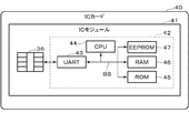
- FIG. 4 is a diagram showing a hardware configuration example of the IC card 40 shown in FIG.
- the IC card 40 includes an IC module 41 including a contact portion 36 and an IC chip 42.
- the IC chip 42 includes a UART (Universal Asynchronous Receiver Transmitter) 43, a CPU 44, a ROM (Read Only Memory) 45, a RAM (Random Access Memory) 46, and an EEPROM (registered trademark) (Electrically Erasable Programmable ROM) 47.
- UART Universal Asynchronous Receiver Transmitter
- CPU 44 central processing unit
- ROM Read Only Memory
- RAM Random Access Memory
- EEPROM registered trademark
- each configuration (43 to 47) is connected via an internal bus BS.
- the UART 43 performs serial data communication with the communication control device 30 (31) via the SIO terminal described above.
- the UART 43 outputs data (for example, 1-byte data) obtained by converting the serial data signal received via the SIO terminal to parallel to the internal bus BS. Further, the UART 43 serially converts the data acquired via the internal bus BS and outputs the data to the communication control device 30 (31) via the SIO terminal.
- the UART 43 receives a command from the communication control device 30 (31) via the SIO terminal, for example. Further, the UART 43 transmits a response to the communication control device 30 (31) via the SIO terminal.
- the CPU 44 executes a program stored in the ROM 45 or the EEPROM 47 to perform various processes on the IC card 40.
- the CPU 44 executes command processing according to the command received by the UART 43, for example, via the contact unit 36.
- the ROM 45 is, for example, a non-volatile memory such as a mask ROM, and stores data such as a program for executing various processes of the IC card 40 and a command table.
- the RAM 46 is, for example, a volatile memory such as an SRAM (Static RAM), and temporarily stores data used when performing various processes of the IC card 40.
- the EEPROM 47 is, for example, an electrically rewritable nonvolatile memory.
- the EEPROM 47 stores various data used by the IC card 40.
- the EEPROM 47 stores information used for various services (applications) using the IC card 40, for example.
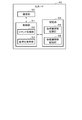
- FIG. 5 is a block diagram showing a functional configuration example of the IC card 40 shown in FIG.
- the IC card 40 includes a communication unit 50, a control unit 51, and a storage unit 54.
- each unit of the IC card 40 shown in FIG. 5 is realized by using the hardware of the IC card 40 shown in FIG.
- the communication unit 50 is realized by, for example, the UART 43, the CPU 44, and a program stored in the ROM 45, and transmits and receives commands and responses to and from the communication control device 30 (31) via the contact unit 36, for example. I do. That is, the communication unit 50 receives a command (processing request) requesting a predetermined process from the communication control device 30 (31), and transmits a response (processing response) to the command to the communication control device 30 (31). The communication unit 50 stores the received data received from the communication control device 30 (31) via the UART 43 in the RAM 46. Further, the communication unit 50 transmits the transmission data stored in the RAM 46 to the communication control device 30 (31) via the UART 43.
- the control unit 51 is realized by, for example, the CPU 44, the RAM 45, the ROM 46, or the EEPROM 47, and integrally controls the IC card 40.
- the control unit 51 includes a command processing unit 52 and an encryption/decryption unit 53.
- the process performed by the command processing unit 52 is an example of “authentication process”.
- the process performed by the encryption / decryption unit 53 is an example of the “encryption / decryption process”.
- the command processing unit 52 executes various command processing.
- the command processing unit 52 performs an SSL/TLS handshake, for example, as command processing for requesting an HTTPS request described later.
- SSL/TLS handshake key information and the like necessary for encrypted communication are exchanged, and mutual authentication with a communication destination device is performed.
- the mutual authentication is an authentication process in which the communication control device 30 on the client side and the communication control device 31 on the server side mutually confirm that they are properly authenticated before communication. is there.
- the encryption/decryption unit 53 executes a process of encrypting the data and a process of decrypting the encrypted data.
- the encryption/decryption unit 53 encrypts the data output by the device (the client device 10 or the server device 20) acquired via the communication unit 50. Further, the encryption / decryption unit 53 decrypts the encrypted data from the network NW acquired via the communication unit 50.
- the storage unit 54 is, for example, a storage unit composed of an EEPROM 47, and includes a certificate information storage unit 55 and a secret information storage unit 56.
- the certificate information storage unit 55 stores the certificate issued by the communication control management device 5 for the device (the client device 10 or the server device 20).
- the certificate information storage unit 55 of the IC card 40 mounted on the communication control device 30 on the client side stores information indicating the client certificate.
- information indicating the server certificate is stored in the certificate information storage unit 55 of the IC card 40 attached to the communication control device 31 on the server side.
- the secret information storage unit 56 stores the secret key for the device (client device 10 or server device 20) issued by the communication control management device 5. Specifically, the secret information storage unit 56 of the IC card 40 mounted on the client-side communication control device 30 stores information indicating the secret key issued to the client-side communication control device 30. .. The certificate information storage unit 55 of the IC card 40 mounted on the server-side communication control device 31 stores information indicating the private key issued to the server-side communication control device 31.
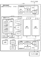
- FIG. 6 is a block diagram showing a configuration example of the communication control management device 5 shown in FIG.
- the communication control management device 5 includes, for example, a NW (network) communication unit 60, a control unit 61, and a storage unit 66.
- the NW communication unit 60 is connected to the network NW and communicates with the communication control device 30 (31) via the network NW.
- the control unit 61 includes a processor such as a CPU, for example.
- the control unit 61 realizes various processes by the processor executing programs.
- the control unit 61 comprehensively controls the communication control management device 5. Further, the control unit 61 mainly operates as a private certification authority that recognizes the validity of the communication control device 30 (31).
- the control unit 61 functions as a key generation unit 62, a certificate issuing unit 63, a certificate updating unit 64, a certificate management unit 65, and a management unit 69 when the processor executes a program. Execute the process to realize.
- the key generation unit 62 issues a private key corresponding to the public key included in the certificate described later, based on the authentication application from the communication control device 30 (31), for example.
- the certificate issuing unit 63 issues a certificate that recognizes the validity of the communication control device 30 (31), for example, based on the certification application from the communication control device 30 (31).
- the certificate includes a public key and information indicating the owner of the communication control device 30 (31).
- the certificate renewal unit 64 renews the certificate by setting a new expiration date for the certificate whose expiration date has passed.
- the certificate renewal unit 64 issues, for example, a certificate with an extended expiration date of the certificate issued to the communication control device 30 (31) based on the renewal application from the communication control device 30 (31). Then, the issued certificate is transmitted to the communication control device 30 (31).
- Information indicating the issued certificate is received by the communication control device 30 (31) and is stored in the certificate information storage unit 405 of the IC card 40 of the communication control device 30 (31). ) Certificate is extended.
- the certificate management unit 65 manages the certificates that have already been issued.
- the certificate management unit 65 for example, when the IC card 40 mounted on the communication control device 30 (31) is tampered with, stolen, or the like, and mutual validity is not proved in mutual authentication, the communication control device 30 (31). Perform the process of invalidating the certificate issued to.
- the certificate management unit 65 receives a certificate issued to the communication control device 30 (31) and other communication devices based on an inquiry from the communication control device 30 (31) by the certificate management unit 65. You may make it respond whether it was issued. Further, the certificate management unit 65 may periodically check whether the issued certificate is used by the legitimate communication control device 30 (31).
- the management unit 69 manages the communication control device 30 (31). For example, the management unit 69 remotely controls the mutual authentication performed by the communication control device 30 (31) via the network NW.
- the storage unit 66 includes, for example, a key information storage area 67 and a certificate information storage area 68.
- the key information storage area 67 stores, for example, information indicating an already issued public key or a private key.
- the certificate information storage area 68 stores, for example, information indicating a certificate that has already been issued.
- the key information storage area 67 and the certificate information storage area 68 are referred to, for example, when the key generation unit 62 issues a private key and when the certificate issuing unit 63 issues a certificate. Further, in the key information storage area 67, information indicating a private key issued by the key generation unit 62 is stored. Further, in the certificate information storage area 68, information indicating a certificate issued by the certificate issuing unit 63 is stored.
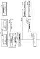
- FIG. 7 is a sequence chart showing an example of processing performed by the communication system 1.
- the client device 10 When transmitting the imaging data to the server device 20, the client device 10 first transmits an HTTP request to the server device 20 (step S1).
- the HTTP request transmitted by the client device 10 is acquired by the communication control device 30 on the client side (step S2).
- the client-side communication control device 30 acquires the HTTP request transmitted by the client device 10, the client-side communication control device 30 transmits an HTTPS request (Client Hello) to the server-side communication control device 31 (step S3). As a result, a handshake between the communication control device 30 on the client side and the communication control device 31 on the server side is started (step S4).
- the Client Hello transmitted by the communication control device 30 on the client side includes, for example, information indicating the version of TLS and a list of encryption methods and algorithms used for communication.
- the server-side communication control device 31 transmits an HTTPS response (Server Hello) to the client-side communication control device 30 as a response to the Client Hello.
- the Server Hello transmitted by the communication control device 31 on the server side includes, for example, information selected by the server device 20 from the options presented by the Client Hello. In other words, the communication control device 31 on the server side selects a presentation from the communication control device 30 on the client side, thereby determining a specific encryption algorithm in communication.
- the communication control device 31 on the server side sends necessary information to the common key used for encrypted communication.
- the information required for the common key includes, for example, information indicating the public key issued to the server device 20 and its certificate, and information requesting that the public key of the client device 10 and its certificate be sent. Be done.
- the communication control device 30 on the client side sends the communication control device 31 on the server side the information necessary for the public key issued to the own device, its certificate, and the common key used for encrypted communication.
- Mutual authentication between the communication control device 30 on the client side and the communication control device 31 on the server side is performed, for example, as follows.
- the communication control device 30 on the client side generates a signature from the Server Hello received so far and sends it to the communication control device 31 on the server side.
- the server-side communication control device 31 verifies the signature received from the client-side communication control device 30 based on the certificate received from the client-side communication control device 30. If the verification is successful, the server-side communication control device 31 determines that the certificate definitely belongs to the client-side communication control device 30. Further, the server-side communication control device 31 generates a signature from the Client Hello received so far and sends it to the client-side communication control device 30.
- the communication control device 30 on the client side verifies the signature received from the communication control device 31 on the server side based on the certificate received from the communication control device 31 on the server side. If the verification is successful, the communication control device 30 on the client side determines that the certificate is definitely that of the communication control device 31 on the server side.
- the client-side communication control device 30 and the server-side communication control device 31 are used for encryption, respectively. Generate and exchange a common key.
- the server-side communication control device 31 terminates the handshake if the public key and its certificate sent from the client-side communication control device 30 are certificates that are acceptable to the server-side communication control device 31.
- the communication control device 31 on the server side transmits an HTTP request to the server device 20 (step S5).
- the HTTP request is an HTTP request transmitted from the client device 10 in step S1.
- the HTTP request transmitted by the communication control device 31 on the server side is received by the server device 20 (step S6).
- the server device 20 recognizes that the HTTP request has been requested from the client device 10. Therefore, the server device 20 responds with an HTTP response to the client device 10 (step S7).
- the HTTP response transmitted by the server device 20 is acquired by the communication control device 31 on the server side (step S8).
- the communication control device 31 on the server side encrypts the acquired HTTP response from the server device 20 using the common key determined in the handshake of step S4 (step S9).
- the HTTP response encrypted by the communication control device 31 on the server side is received by the communication control device 30 on the client side via the network NW (step S10).
- the communication control device 30 on the client side decrypts the received HTTP response using the common key (step S11).
- the HTTP response decrypted by the communication control device 30 on the client side is acquired by the client device 10 (step S12).
- the client device 10 receives the decrypted HTTP response (step S13). At this time, the client device 10 recognizes that the HTTP response is returned from the server device 20. Therefore, the client device 10 transmits the imaging data to the server device 20 (step S14).
- the image pickup data transmitted by the client device 10 is acquired by the communication control device 30 on the client side (step S15).
- the communication control device 30 on the client side encrypts the imaging data transmitted by the client device 10 using a common key (step S16).
- the imaged data encrypted by the communication control device 30 on the client side is received by the communication control device 31 on the server side via the network NW (step S17).
- the communication control device 31 on the server side decrypts the received imaging data using the common key (step S18).
- the image pickup data decrypted by the communication control device 31 on the server side is acquired by the server device 20 (step S19).
- the server device 20 receives the decrypted imaging data (step S20). At this time, the server device 20 recognizes that the imaging data from the client device 10 has been received.
- the communication control device 30 on the client side communicates with the communication destination. Do not allow communication. Specifically, the communication control device 30 on the client side does not output the information transmitted from the communication destination to the client device 10. This is because if the mutual authentication is not performed correctly, the communication destination may be an unauthorized communication device disguised as the communication control device 31 on the server side. In this case, the communication control device 30 on the client side may transmit, for example, a communication record when mutual authentication is not performed correctly to the communication control management device 5. As a result, the communication control management device 5 can acquire a communication record when mutual authentication is not correctly performed, and grasp the pattern or frequency of unauthorized communication with the client-side communication control device 30 under management. By doing so, it is possible to monitor network abnormalities.
- the communication control device 30 on the client side is a communication destination based on a destination list indicating information of a communication device that allows communication to the client device 10 instead of mutual authentication in the handshake performed in step S4 of the above flowchart. It may be determined whether or not to allow communication with.
- the information about the communication device shown in the destination list is, for example, a URL (Uniform Resource Locator).
- URL Uniform Resource Locator
- control unit 33 may update the destination list.
- the control unit 33 stores, for example, a URL of a communication destination permitted to communicate with the client device 10 and a communication destination URL not permitted to communicate with the client device 10 for a certain period. Then, the control unit 33 updates the destination list by, for example, re-registering the URL of the communication destination with which communication has been performed for a certain period of time among the URLs registered in the destination list.
- the communication control device 30 on the client side may transmit the communication destination URL that is permitted to communicate and the communication destination URL that is not permitted to communicate to the communication control management device 5 for a certain period of time.
- the communication control management device 5 may update the destination list based on the communication destination URL that has communicated with the communication control device 30 on the client side.
- the communication control management device 5 it is possible to collectively manage the communication devices that communicate with the communication control device 30 on the client side under the control of the communication control management device 5.
- the client-side communication control device 30 verifies whether or not the content of the information (for example, the firmware update program) transmitted to the client device 10 after the handshake performed in step S4 is established is correct. You may do it.
- the control unit 33 of the client-side communication control device 30 verifies using a verification key (verification key).
- the communication control management device 5 may transmit the verification key to, for example, the communication control device 30 on the client side and the communication control device 31 on the server side.
- the communication control device 31 on the server side generates a hash value from the information (plain text) transmitted to the client device 10, and encrypts the generated hash value with the verification key. Then, the communication control device 31 on the server side further encrypts the plaintext and the encrypted hash value with a secret key, and sends the encrypted hash value to the client device 10. Further, the communication control device 30 on the client side decrypts the information using the common key, and acquires the plaintext and the encrypted hash value.
- the communication control device 30 on the client side generates a hash value from the acquired plaintext and decrypts the encrypted hash value with the verification key.
- the communication control device 30 on the client side determines that the information transmitted to the client device 10 is correct. In this case, the communication control device 30 on the client side outputs the decrypted information (plain text) to the client device 10.
- the communication control device 30 on the client side determines that the information transmitted to the client device 10 is the server device 20 or the communication control on the server side. It is determined that there is a possibility that the information is unauthorized information transmitted from an unauthorized communication device that is disguised as the device 31. In this case, the client-side communication control device 30 does not output the decrypted information (plain text) to the client device 10.
- the client device 10 can receive only the information that has been verified to have the correct content. Further, normally, it is considered that the client device 10 determines whether or not the content of the update program is correct when the firmware is updated. However, instead of the client device 10, the communication control device 31 on the server side instructs the client device 10 to do so. By verifying the content of the transmitted information, the processing load on the client device 10 can be reduced.
- a control device 31 is provided.
- the communication control device 30 on the client side encrypts the information from the client device 10 and transmits it to the communication control device 31 on the server side via the network NW, and the information from the network NW (the server encrypted by the communication control device 31) is transmitted.
- Information from the device 20) is decoded and transmitted to the client device 10.
- the communication control device 31 on the server side encrypts the information from the server device 20 and transmits it to the communication control device 30 on the client side via the network NW, and the information from the network NW (the client encrypted by the communication control device 30 is transmitted.
- Information from the device) is decrypted and transmitted to the server device 20.
- the communication system 1 can improve the safety of the social infrastructure system without changing the social infrastructure system.
- the HTTP protocol imaging data (so-called plain text) transmitted from the client device 10 to the server device 20 is combined with the SSL/TLS protocol by the communication control device 30 on the client side, for example, to improve security. This is because it is replaced by HTTPS.
- the control data transmitted to the server device 20 or the client device 10 is encrypted, but is decrypted by the communication control device 30 on the client side and received by the client device 10, so that the client device 10 Since it is not necessary to perform the decryption process on the existing device, the existing device can be used as it is without being changed.
- the communication control device 30 on the client side and the communication control device 31 on the server side perform mutual authentication, it is possible to improve safety as compared with the case of performing authentication in only one direction. ..
- a valid client certificate is issued and managed for the unspecified number of client terminals. It is not realistic to continue.
- the communication control device 30 on the client side and the communication control device 31 on the server side can perform mutual authentication, and the security can be improved.
- a client terminal that does not have a client certificate may be required to enter an ID and password issued by the server device in order to communicate with the server device.
- password authentication in order to maintain security, a long character string combining letters and numbers may be required for the password, or the password may be changed regularly.
- management becomes troublesome, and there are cases where passwords are leaked, such as when the password is written in a memo or recorded in a web browser.
- the communication control device 30 on the client side since the communication control device 30 on the client side has the client certificate, mutual authentication can be reliably performed with the server device 20. Therefore, password authentication becomes unnecessary. Therefore, the trouble of entering the password and the trouble of periodically changing and managing the password are eliminated, and the convenience of the user is improved. That is, safety can be maintained without imposing a burden on the user.
- the client device 10 and the server device 20 are illegal because mutual authentication is performed between the client device 10 and the server device 20 via the communication control device 30 (31). Will not be hijacked. That is, in the communication system 1, it is possible to take measures against ransomware.
- the terminal also called a stray device
- the terminal will be illegally hijacked and used as an illegal terminal that attacks malware etc.
- mutual authentication is performed between the client device 10 and the server device 20 via the communication control device 30 (31), so that the administrator inside the network NW can Even if an absent terminal is illegally hijacked and used for an attack, it is possible to prevent infection with malware or the like.
- the server device 20 is connected to the communication control device 31 on the server side, and the authentication process is not performed inside the server device 20. Therefore, it is not necessary to hold a certificate or the like inside the server device 20, and it becomes clear that the server device 20 connected to the server-side communication control device 31 is under the control of the communication control management device 5.
- the server device 20 already has a functional unit corresponding to the communication control device 31 on the server side, the communication control device 31 on the server side is not necessarily physically connected between the server device 20 and the network NW. You don't have to.
- the functional unit corresponding to the communication control device 31 on the server side originally possessed by the server device 20 performs the authentication process with the communication control device 30 on the client side.
- control unit 401 of the IC card 40 is made to perform at least one of mutual authentication and encryption / decryption processing. Therefore, the device cost of the communication control device 30 (31) can be suppressed.
- the IC card 40 mounted on the communication control device 30 (31) performs at least one of mutual authentication and encryption / decryption processing.
- the configuration for performing mutual authentication and encryption/decryption processing is not limited to the IC card.
- the IC card 40 described above has a storage function for storing a private key and a client certificate (or a server certificate), and a processing function for performing at least one of mutual authentication and encryption / decryption processing.
- the SIM card may be a SIM card having an IC chip mounted thereon, or the card form may not be adopted.
- the IC card 40 of the communication control device 30 on the client side is detachably attached to the communication control device 30 on the client side.
- the IC card 40 and the communication control device 30 on the client side can be separated. Therefore, when exchanging either one, the one device may be exchanged.
- the IC card 40 and the communication control device 30 on the client side are integrated, when the part corresponding to the IC card 40 is replaced, the entire communication control device 30 on the client side must be replaced.
- the communication system 1 further includes a communication control management device 5, and the communication control management device 5 stores a private key stored in an IC card 40 mounted on the communication control device 30 on the client side and a client certificate on the client side.
- the secret key stored in the IC card 40 mounted on the communication control device 31 on the server side and the server certificate are transmitted to the communication control device 31 on the server side.
- the communication system 1 can perform a handshake and determine a common key by using a legitimate secret key and certificate issued by the communication control management device 5, and in addition to the above-described effect, the social key The safety of the infrastructure system can be further improved.
- the configuration of the communication system 1 is not limited to the above-mentioned example.
- the communication control device 30 (31) may use an HSM (Hardware Security Module) that realizes the functions of the communication control device 30 (31) by hardware based on the processing load. That is, the communication control device 30 (31) is not limited to the configuration in which an IC card is mounted as long as secure processing is possible, and an IC chip or an IC module that can realize the function of the communication control device 30 (31) is used. It may be the configuration that was used.
- HSM Hardware Security Module
- secure communication using the SSL/TLS protocol may be constantly performed, or whether communication using the SSL/TLS protocol may be selectable. Further, only the communication in one direction of the bidirectional communication between the client device 10 and the server device 20 may be the communication using the SSL / HTTPS protocol. Further, secure communication using the SSL / HTTPS protocol may be performed at all times, or it may be possible to select whether or not to perform communication using the SSL / HTTPS protocol.
- communication using the SSL/TLS protocol may be constantly performed to store unauthorized access to the client device 10 and the server device 20.
- a record of unauthorized access may be transmitted to the communication control management device 5.
- the communication control management device 5 can recognize whether or not there is an unauthorized access, and can detect a warning sign before a large-scale attack on the entire system is started and take countermeasures.
- the communication control device 30 (31) periodically confirms whether or not the connection with the client device 10 or the server device 20 to which the own device is connected is maintained. May be. In this case, information indicating the connection status may be transmitted to the communication control management device 5.
- the communication control management device 5 determines that the communication control device 30 (31) is disconnected from the client device 10 or the server device 20 when the information indicating the connection state cannot be received from the communication control device 30 (31), The disconnected communication control device 30 (31) is invalidated. By doing so, the communication control management device 5 prevents the disconnected communication control device 30 (31) from being connected to an unauthorized device and being misused for spoofing.
- the IC card 40 mounted on the communication control device 30 (31) may be equipped with a highly tamper-resistant chip called a secure element that has acquired CC (Common Criteria/ISO15408) certification. .. By using this chip to store a certificate containing a private key and a public key, extremely high security can be maintained.
- CC Common Criteria/ISO15408
- the program of the client device 10 may be updated from the server device 20, the communication control management device 5, or the like via the communication control device 30 (31).
- the function of the client device 10 can be safely updated.
- the firmware transmitted from the server device 20 is, for example, signed by the server device 20 encrypted by the communication control device 31 on the server side. Granted.
- the client device 10 can determine that the transmitted firmware is definitely the firmware transmitted from the server device 20 by decoding the signature by the communication control device 30 on the client side.
- the client device 10 is erroneously based on the unauthorized firmware. It is possible to exclude that updates are made.
- the firmware can be safely updated from the server device 20, the communication control management device 5, and the like to the client device 10. It is also possible to reduce the work cost as compared with the case where the firmware is updated by physically moving the plurality of client devices 10 to the place where each client device 10 is installed.
- the client device 10 may be started or stopped from the server device 20, the communication control management device 5, or the like via the communication control device 30 (31). By starting or stopping (remote activation) via the communication control device 30 (31), the function of the client device 10 can be safely updated, and secure remote control can be realized.
- At least one of the client device 10 and the server device 20 may be a device that performs wireless communication via a wireless LAN or the like.
- the communication control device 30 on the client side has a wireless communication function and encrypts the data transmitted by the client device 10 and encrypts the data.
- the data is transmitted to the server device 20 by wireless communication.
- the communication control device 30 on the client side communicates with the communication control device 31 on the server side
- the communication destination of the communication control device 30 on the client side is limited to this.
- the communication control device 30-1 on the client side may communicate with the communication control device 30-2 on the client side.
- the communication control device 30-1 on the client side receives a signal to start communication from the communication control device 30-2 on the client side, it first performs mutual authentication with the communication control device 30-2 on the client side, and the client It is confirmed that the communication control device 30-2 on the side is a valid communication terminal.
- the communication control device 30-1 on the client side outputs the information received from the communication control device 30-2 on the client side to the client device 10.
- an authenticator to the transmitted data using encryption, it is possible to detect falsification of communication information and identify the sender. Therefore, in the communication system 1, in the communication between the communication control device 30 on the client side and the communication control device 31 on the server side and the communication between the communication control devices 30 on the client side, "from the correct partner" and "tampering" are performed. You can be assured that you will not "receive data.”
- FIG. 8 is a diagram showing a first configuration example of the communication system 100 according to the first embodiment.
- the communication control device 30 is replaced with the communication control device 101 in the system configuration shown in FIG.
- the communication control apparatus 101 has a plurality of communication devices 111A and 111B provided in parallel between the network NW and the client apparatus 10.
- each device other than the communication control device 101 in the communication system 100 can be realized by the same configuration as the device shown in FIG. Therefore, detailed description of configurations other than the communication control device 101 will be omitted below.
- the communication control device 31 may also be configured to include a plurality of communication devices provided in parallel between the network NW and the server device 20, similarly to the communication control device 101.
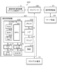
- FIG. 9 is a block diagram showing a configuration example of the communication control device 101 in the first configuration example of the communication system 100 according to the first embodiment.
- the communication control apparatus 101 has a first communication device 111A and a second communication device 111B arranged in parallel as a plurality of communication devices 111.
- the first communication device 111A and the second communication device 111B are connected in parallel between the hub 114 connected to the network NW side and the hub 115 connected to the client side.
- Each of the first communication device 111A and the second communication device 111B has a configuration that executes the same communication process as the communication control device 30 shown in FIG. 1 described above.
- the communication control device 101 has a power supply 116 and a memory I / F 117 shared by the first communication device 111A and the second communication device 111B.
- the power supply 116 is connected to an external power supply and supplies the power from the external power supply to the communication devices 111A and 111B.
- the memory I/F 117 is an interface for setting a memory device 118 such as a memory card.
- the memory I / F 117 is set with a memory device 118 that stores information applied to the communication devices 111A and 111B such as initial setting information.
- the memory device 118 set in the memory I / F 117 may store data (for example, log data) supplied from the communication devices 111A and 111B.
- the communication control device 101 may be realized as a system in which a plurality of communication devices having the same configuration as the communication control device 30 are arranged in parallel.
- each communication device may be configured to include a power supply, a memory I / F, and the like.
- the first communication device 111A and the second communication device 111B may be arranged in parallel between the network NW and the client device 10.
- the communication control device 101 may have a configuration in which the first communication device 111A and the second communication device 111B are provided with interfaces for connecting to the network NW and the client device 10, respectively, without providing the hubs 114 and 115. good.
- each communication control device 101 the first communication device 111A and the second communication device 111B are arranged in parallel between the network NW and the client device 10, and one of them is in the normal communication mode (first communication mode). Execute communication processing.
- the communication control device 101 realizes communication control between the network NW and the client device 10 by switching the communication devices 111A and 111B that communicate in the normal communication mode.
- the normal communication mode is assumed to be an operation mode in which communication involving encryption and decryption of transmission/reception data using a common key based on mutual authentication with the server-side communication control device 31 as described above is performed. .. Further, in the present embodiment, the communication control device 101 executes communication in the normal communication mode in the whitelist operation mode that allows communication with the destinations listed in the whitelist described later.
- the first communication device 111A and the second communication device 111B provided in parallel in the communication control device 101 may be realized by two independent software for communication processing.
- one communication device may be operated as two communication devices that are arranged in parallel and realized by two pieces of software.
- Each communication device 111 has a function of detecting its own failure, unauthorized access, malware infection, or the like. For example, the communication device 111 transmits, to the communication control management device (device management server) 5, information indicating a failure such as a failure, unauthorized access or malware infection, or a failure such as communication failure. Further, each communication device 111 switches the operation mode according to an instruction from the communication control management device 5. For example, each communication device 111 switches from the non-communication state to the normal communication mode or switches from the normal communication mode to the non-communication state in response to an instruction from the communication control management device 5.
- each communication device 111 (111A, 111B) has a controller 120, a bridge 132, a hub 133, a bridge 134, a reader/writer 135, and an IC card 140.
- the controller 120 controls the communication device 111.
- the controller 120 includes an MPU 121, a RAM 122, a SAM 123, a data memory 124, and the like.
- the MPU 121 is an example of a processor that controls the controller 120.
- the MPU 121 implements various processes by executing a program stored in the data memory 124 or the like.
- the controller 120 executes processes such as communication control, failure detection, communication failure detection, self-diagnosis, and log information collection when the MPU 121 executes a program.
- the controller 120 causes the MPU 121 to execute a program, thereby performing mutual authentication processing with the server-side communication control device 31, encryption processing of data transmitted from the client device 10 to the network NW, and client processing via the network NW. You may make it perform the decoding process etc. of the encrypted data transmitted to an apparatus. Further, the controller 120 may request the IC card 140 connected via the reader / writer 135 to perform at least one of mutual authentication processing, encryption processing, and decryption processing.
- the RAM 122 is a random access memory.
- the RAM 122 functions as a working memory that holds work data.
- the SAM 123 is a serial access memory.
- the data memory 124 is a rewritable nonvolatile memory.
- the data memory 124 stores programs and setting information.
- the data memory 124 stores a white list showing a list of destinations that are allowed to communicate.
- the controller 120 refers to the whitelist stored in the data memory 124 for communication. Execute. Further, the controller 120 may rewrite the white list in the data memory 124 in response to an instruction from the communication control management device 5.
- the communication device 111 may be put into a non-communication state by deleting all the destinations on the white list.
- the data memory 124 may store log information indicating the operating state of the communication device. The log information stored in the data memory 124 is sent to the communication control management device (device management server) 5 or used for self-diagnosis processing or the like.
- the bridges 132 and 134 function as a communication interface (communication unit). Bridges 132 and 134 are connected to controller 120 via hub 133. The bridge 132 executes communication on the network NW side in the communication device 111. The bridge 132 realizes communication as the NW communication unit 32 shown in FIG. The bridge 132 supplies the data received from the network NW to the controller 120 via the hub 133. Further, the bridge 134 sends the data encrypted by the controller 120 or the IC card 140 to the network NW.
- the bridge 134 executes communication on the client device 10 side in the communication device 111.
- the bridge 134 realizes communication as the device communication unit 34 shown in FIG.
- the bridge 134 supplies the data from the client device 10 to the controller 120 via the hub 133.
- the bridge 134 transmits the data obtained by decrypting the encrypted data from the network NW with the controller 110 or the IC card 140 to the client device 10.
- the reader/writer 135 and the IC card 140 correspond to the reader/writer 35 and the IC card 40 shown in FIG. 3 described above.
- the IC card 140 can be realized by having the same configuration as the IC card 40 shown in FIG. 4 described above. Further, the IC card 140 has the same processing function as the IC card 40 shown in FIG. 5 described above, and functions as an example of the authentication unit in the communication control apparatus 101.
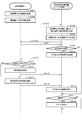
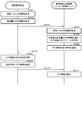
- FIG. 10 is a sequence for explaining an operation example in the communication system 100 having the configuration shown in FIG. 8 according to the first embodiment.
- the first communication device 111A executes communication in the normal operation mode (normal communication mode, first communication mode) based on the whitelist (step S101), and the second communication device 111B is not yet. It is assumed that the communication state is set (step S102).
- the controller 120 of the first communication device 111A monitors the operating state such as the amount of communication data, the communication speed, the communication time, and the error detection frequency, and determines the presence or absence of a failure or communication failure in the first communication device. Detect (step S103). Further, the controller 120 may detect the presence or absence of a defect in the communication device 111A by executing the self-diagnosis at the set timing. Further, each communication device 111 may be provided with a detector that detects a defect, and the controller 120 may acquire the detection result of the detector.
- step S103 If the controller 120 of the first communication device 111A does not detect a malfunction (step S103, NO), the controller 120 continues to execute communication in the normal communication mode. Further, when the controller 120 of the first communication device 111A detects a defect during execution of communication in the normal communication mode (step S103, YES), the controller 120 transmits information indicating the defect to the communication control management device 5.
- Step S105 Information indicating a defect transmitted by the first communication device 111A of the communication control apparatus 101 is acquired by the communication control management apparatus 5 (step S105).
- the control unit 61 of the communication control management device 5 sets the second communication device 111B of the communication control device 101 to the normal communication mode according to the information indicating the failure from the first communication device 111A of the communication control device 101,
- the communication device 111A is controlled so as not to communicate.
- the control unit 61 of the communication control management device 5 refers to the second communication device 111B of the communication control device 101 which is the source of the information indicating the defect.
- An instruction to switch to the normal communication mode is given (step S106).
- the instruction to switch from the communication control management device 5 to the normal communication mode is acquired by the second communication device 111B of the communication control device 101, which is the source of the information indicating the defect (step S107).
- the controller 120 of the second communication device 111B switches the operation mode to the normal communication mode in response to the switching instruction from the communication control management device 5 to the normal communication mode (step S108).
- the control unit 61 of the communication control management device 5 refers to the first communication device 111A of the communication control device 101 which is the source of the information indicating the defect. It is instructed to enter the non-communication state (step S109).
- the instruction to switch to the non-communication state from the communication control management device 5 is acquired by the first communication device 111B, which is the source of the information indicating the failure (step S110).
- the controller 120 of the first communication device 111A switches the operation mode to the non-communication state in response to the switching instruction from the communication control management device 5 to the non-communication state (step S111).
- the operation mode of the first communication device and the second communication device can be switched so that the communication as the communication control device 101 is not interrupted.
- the communication control management device (device management server) 5 sets the first communication device 111A in a non-communication state after the switching to the normal communication mode of the second communication device 111B is completed. Thereby, the communication control management device 5 can reliably ensure the availability of communication in the communication control device 101.
- the communication control apparatus 101 performs communication control in which, when a failure occurs in one communication device that is performing communication in the normal communication mode, the other communication device switches to perform communication in the normal communication mode. It may be realized in the device 101. For example, when the first communication device that is executing communication in the normal communication mode detects a defect, the controller 120 of the first communication device 111A requests the second communication device 111B to switch to the normal communication mode. May be. As a result, the second communication device 111B can be started in the normal communication mode in response to the request, and the first communication device 111A can be made to transition to the non-communication state. In this case, the first communication device and the second communication device can communicate with each other by their addresses.
- FIG. 11 is a diagram showing a second configuration example of the communication system 100 ′ according to the first embodiment.
- the communication system 100'shown in FIG. 11 replaces the communication control device 30 with the communication control device 101'in the system configuration shown in FIG.
- the communication control apparatus 101′ has a plurality of communication devices 111C and 111D arranged in series between the network NW and the client apparatus 10.
- each device other than the communication control device 101′ in the communication system 100′ can be realized by the same configuration as the device shown in FIG. Therefore, detailed description of the configuration of each device other than the communication control device 101'will be omitted below.
- the communication control device 31 is also configured to include a plurality of communication devices arranged in series between the network NW and the server device 20 as in the communication control device 101'. good.
- FIG. 12 is a block diagram showing a configuration example of the communication control device 101′ in the second configuration example of the communication system 100′ according to the first embodiment. In the configuration example illustrated in FIG.
- the communication control apparatus 101′ includes, as the plurality of communication devices 111, a first communication device 111C and a second communication device 111D that are arranged in series.
- the first communication device 111C connected to the network NW and the second communication device 111D connected to the client device 10 are connected in series.
- the communication control device 101' has a power supply 116 and a memory I / F 117 shared by the first communication device 111C and the second communication device 111D.
- the power supply 116 is connected to an external power supply and supplies the power from the external power supply to the communication devices 111C and 111D, as in FIG.
- the memory I / F 117 is an interface for setting a memory device 118 such as a memory card, as in FIG.
- the communication control device 101' may be realized as a system in which a plurality of communication devices having the same configuration as the communication control device 30 are arranged in series. In such a system, the plurality of communication devices 111'may each have a configuration such as a power supply and a memory I / F.
- Each of the first communication device 111C and the second communication device 111D has a configuration that executes the same communication process as the communication control device 30 shown in FIG. 1 described above. That is, in each communication control device 101, one of the first communication device 111C and the second communication device 111D arranged in series between the network NW and the client device 10 is in the normal communication mode (first communication). The mode) communicates, and the other communicates in the pass-through mode (second communication mode).
- the pass-through mode (second communication mode) is a communication mode in which input information is passed as it is and output.
- the normal communication mode is an operation mode in which communication is performed with encryption and decryption of transmitted / received data using a common key based on mutual authentication with the communication control device 31 on the server side as described above.
- the communication control device 101' is assumed to execute the communication in the whitelist operation mode which allows the communication with the destination in the whitelist as described above in the normal operation mode.
- the first communication device 111C and the second communication device 111D provided in series in the communication control device 101′ may be realized by two independent software for communication processing.
- one communication device may be operated as two communication devices that are arranged in parallel and realized by two pieces of software.
- Each communication device 111' has a function of detecting its own failure, unauthorized access, malware infection, or the like.
- the communication device 111' notifies the communication control management device (device management server) 5 of information indicating a failure such as a failure, an unauthorized access, or a malware infection, or a communication failure.
- each communication device 111's switches an operation mode according to an instruction from the communication control management device 5. For example, each communication device 111'switches from the pass-through mode to the normal communication mode or switches from the normal communication mode to the pass-through mode in response to an instruction from the communication control management device 5.
- each communication device 111′ (111C, 111D) has a controller 120, a bridge 132, a hub 133, a bridge 134, a reader/writer 135, an IC card 140, and the like, as in the configuration shown in FIG. I shall. Further, it is assumed that the controller 120 has an MPU 121, a RAM 122, a SAM 123, a data memory 124, and the like. Since each of these configurations can be realized with the same configuration as each configuration shown in FIG. 9, detailed description will be omitted.
- FIG. 13 is a sequence for explaining an operation example in the communication system 100'with the configuration shown in FIG. 11 according to the first embodiment.
- the first communication device 111C executes communication in the normal operation mode (normal communication mode) based on the whitelist (step S121), and the second communication device 111D operates in the pass-through mode. (Step S122).
- the controller 120 of the first communication device 111C monitors the operation state such as the communication data amount, the communication speed, the communication time, the error detection frequency, and the like to determine whether there is a failure or a communication failure in the first communication device. It is detected (step S123). Further, the controller 120 may detect the presence or absence of a defect in the communication device 111A by executing the self-diagnosis at the set timing. Further, each communication device 111 may be provided with a detector that detects a defect, and the controller 120 may acquire the detection result of the detector.
- step S123 If the controller 120 of the first communication device 111C does not detect any malfunction (NO in step S123), the controller 120 continues to execute communication in the normal communication mode. Further, when the controller 120 of the first communication device 111C detects a defect during communication in the normal communication mode (YES in step S123), the controller 120 notifies the communication control management device 5 of information indicating the defect (step S124).
- Information indicating a defect notified by the first communication device 111C of the communication control apparatus 101' is acquired by the communication control management apparatus 5 (step S125).
- the control unit 61 of the communication control management device 5 sets the second communication device 111D of the communication control device 101'in the normal communication mode according to the information indicating the defect from the first communication device 111C of the communication control device 101'.
- the first communication device 111C is controlled to be in the pass-through mode.
- the control unit 61 of the communication control management device 5 refers to the second communication device 111D of the communication control device 101'which is the source of the information indicating the defect.
- the instruction to switch to the normal communication mode from the communication control management device 5 is acquired by the second communication device 111D in the communication control device 101′ that is the source of the information indicating the malfunction (step S127).
- the controller 120 of the second communication device 111D switches the operation mode to the normal communication mode in response to the switching instruction from the communication control management device 5 to the normal communication mode (step S128).
- the control unit 61 of the communication control management device 5 sends the information indicating the defect to the first communication device 111C of the communication control device 101'.
- the instruction to switch to the pass-through mode from the communication control management device 5 is acquired by the first communication device 111C, which is the source of the information indicating the failure (step S130).
- the controller 120 of the first communication device 111C switches the operation mode to the pass-through mode in response to the switching instruction from the communication control management device 5 to the pass-through mode (step S131).
- the communication control device has a redundant configuration in which a plurality of communication devices are provided.
- the communication control device even if a failure or a communication failure occurs in the communication control device for ensuring the security in data communication via the network, the communication can be continued without interruption. It is possible to realize communication operation with reliable availability.
- FIG. 14 is a diagram illustrating a configuration example of the communication system 200 according to the second embodiment.
- the communication control device 30 on the client side is replaced with the communication control device 201 in the system configuration shown in FIG.
- the communication control apparatus 201 includes a plurality of communication devices 211A, 211B, and 211C arranged in parallel between the network NW and the client apparatus 10 via the distributed controllers 212A and 212B. Have.
- each device other than the communication control device 201 in the communication system 200 can be realized by the same configuration as the device shown in FIG. Therefore, detailed description of configurations other than the communication control device 200 will be omitted.
- the communication control device 31 on the server side like the communication control device 201, also has a plurality of communications arranged in parallel between the network NW and the server device 20 via a distributed controller. It may be configured to include a device.
- FIG. 15 is a block diagram showing a configuration example of the communication control device 201 in the configuration example of the communication system 200 according to the second embodiment.
- the communication control device 201 has three communication devices 211A, 211B, 211C arranged in parallel as a plurality of communication devices 211.
- the plurality of communication devices 211A to 211C are connected in parallel between the distributed controller 212A connected to the network NW and the distributed controller 212B connected to the client device 10.
- Each of the plurality of communication devices 211A to 211C has a configuration that executes the same communication processing as the communication control device 30 shown in FIG. 1 described above.
- the distributed controllers 212A and 212B control to distribute the load of communication processing to the plurality of communication devices 211A to 211C. Therefore, the controllers included in the respective communication devices 211A to 211C can also perform the encryption / decryption process and the mutual authentication process using the certificate.
- the communication control device 201 has a power supply 216 shared by a plurality of communication devices 211A to 211C and the distributed controllers 212A and 212B.
- the communication control device 201 also has a memory I / F 217 shared by a plurality of communication devices 211A to 211C.
- the power supply 216 is connected to an external power supply and supplies the power from the external power supply to each of the communication devices 211A to 211C and the distributed controllers 212A and 212B.
- the memory I / F 217 is an interface for setting a memory device 218 such as a memory card. For example, a memory device 218 that stores setting information for each communication device 211 is set in the memory I / F 217.
- the number of communication devices 211 arranged in parallel is not limited to three, and may be a plurality. Further, in the communication control device 201, the communication devices 211 arranged in parallel may be those that perform the same communication processing, and may have different processing capacities. Further, in the communication control device 201, the communication devices 211 arranged in parallel may be replaced with those having different processing capacities.
- the communication control device 201 is realized as a distributed device system in which a plurality of communication devices having the same configuration as the communication control device 30 are arranged in parallel between the two distributed controllers 212A and 212B. May be.
- each communication device constituting the distributed device system may be configured as a device that has a power supply, a memory I / F, and the like and can operate independently.
- each communication device 211 (211A to 211C) has a controller 220, a bridge 232, a hub 233, a bridge 234, a reader/writer 235, and an IC card 240.
- the controller 220 controls the communication device 211.
- the controller 220 has an MPU 221, a RAM 222, a SAM 223, a data memory 224, and the like.
- the MPU 221 is an example of a processor that controls the controller 220.
- the MPU 221 realizes various processes by executing a program stored in a data memory 224 or the like.
- the controller 220 executes a program such as communication control, failure detection, communication failure detection, communication status monitoring, self-diagnosis, and log information collection by the MPU 221 executing a program.
- the controller 220 causes the MPU 221 to execute a program, thereby performing mutual authentication processing with the server-side communication control device 31, encryption processing of data transmitted from the client device 10 to the network NW, and client processing via the network NW. You may make it perform the decoding process etc. of the encrypted data transmitted to an apparatus.
- the controller 220 may request the IC card 240 to perform at least one of mutual authentication processing, encryption processing, and decryption processing.
- the RAM 222 is a random access memory.
- the RAM 222 functions as a working memory that holds work data.
- the SAM 223 is a serial access memory.
- the data memory 224 is a rewritable nonvolatile memory.
- the data memory 224 stores programs and setting information.
- the data memory 224 stores a white list showing a list of destinations that are allowed to communicate.
- the controller 220 refers to the white list stored in the data memory 224 and executes communication in the normal communication mode (first communication mode).
- the data memory 224 may store log information indicating the operating state of the communication device.
- the data memory 224 may store information indicating the amount of communication in the communication device.
- the data memory 224 executes self-diagnosis processing such as analysis of log data.
- the bridges 232 and 234 function as communication interfaces (communication units). Bridges 232 and 234 are connected to controller 220 via hub 233. The bridge 232 executes communication on the network NW side in the communication device 211. The bridge 232 realizes communication as the NW communication unit 32 shown in FIG. The bridge 232 supplies the data received from the network NW to the controller 220 via the hub 233. Further, the bridge 234 sends the data encrypted by the controller 220 or the IC card 240 to the network NW.
- the bridge 234 executes communication on the client device 10 side in the communication device 211.
- the bridge 234 realizes communication as the device communication unit 34 shown in FIG.
- the bridge 234 supplies data from the client device 10 to the controller 220 via the hub 233. Further, the bridge 234 sends the data obtained by decrypting the encrypted data from the network NW by the controller 220 or the IC card 240 to the client device 10.
- the reader/writer 235 and the IC card 240 correspond to the reader/writer 35 and the IC card 40 shown in FIG. 3 described above.
- the IC card 240 can be realized by having the same configuration as the IC card 40 shown in FIG. 4 described above. Further, the IC card 240 has a processing function similar to that of the IC card 40 shown in FIG. 5 described above, and functions as an example of an authentication unit in the communication control device 201.
- each distributed controller 212 (212A, 212B) has a controller 251, a memory 252, a hub 253, and an interface (I/F) 254.
- the controller 251 controls the distributed controller 212.
- the controller 251 has a processor and various memories. In the controller 251, various processes are realized by the processor executing the program. For example, the controller 251 performs distributed control of the communication load on the communication devices 211A to 211C by executing the program by the processor.
- the memory 252 stores setting information and the like.
- the memory 252 stores a threshold value for determining the distribution of the communication load.
- the controller 251 determines a communication device to execute communication processing from a plurality of communication devices according to the communication load based on setting information such as a threshold value stored in the memory 252.
- the hub 253 is an interface for connecting the network NW or the client device 10 and the plurality of communication devices 211A to 211C.
- the hub 253 is controlled by the controller 251 as a communication device to be connected.
- the interface 254 is an interface for acquiring setting information and the like.
- the interface 254 is configured as a communication unit for communicating with the communication control management device 5.
- the interface 254 may be configured by a memory reader that reads information from a memory device such as a memory card that stores setting information such as a threshold value.
- the interface 254 may be an interface for connecting an external device that supplies setting information such as a threshold value.
- FIG. 16 is a flowchart for explaining an operation example of the distributed controller 212 (212A, 212B) in the communication system 200 having the configuration shown in FIGS. 14 and 15.
- the distribution controller 212 receives setting information input by the interface 254 or the like for distributed processing by the plurality of communication devices 211A to 211C (S201).
- the controller 251 of the distribution controller 212 (212A or 212B) performs the distributed processing by the plurality of communication devices 211A to 211C based on the input setting information.
- a threshold value for determining is set (step S202).
- the first threshold is a determination reference value for the processing load of the entire communication control apparatus 201 for determining whether or not to perform communication processing with one communication device.
- the controller 251 of the distributed controller 212 executes communication processing with one communication device if the processing load of the communication control apparatus 201 as a whole is less than the first threshold value, and with a plurality of communication devices if the load is equal to or more than the first threshold value. Communication processing shall be executed in a distributed manner.
- the second threshold value is a determination reference value for the processing load of the entire communication control device 201 for determining whether or not the communication processing is executed by the three communication devices.
- the controller 252 of the distributed controller 212 distributes the communication processing among the three communication devices and executes the communication processing if the processing load of the entire communication control apparatus 201 is equal to or more than the second threshold, and is equal to or more than the first threshold and less than the second threshold. In that case, the communication process is divided into two communication devices to execute the communication process.
- the threshold as the setting information for carrying out the distributed processing may be set appropriately.
- the controllers 251 of the distributed controllers 212A and 212B monitor the processing load on the communication device based on the communication amount and the like (step S203). For example, since the communication device 211 executes the decoding process for the information input from the network NW side, the controller 251 of the distributed controller 212A monitors the amount of data input from the network NW side as a processing load. Further, since the communication device 211 executes the encryption process for the information input from the client device 10, the controller 251 of the distributed controller 212B monitors the amount of data input from the client device 10 as a processing load.
- the controller 251 of the distributed controller 212 causes one communication device 211 to execute the communication process (step S205). For example, when a plurality of communication devices are operating, the controller 251 executes communication with only one communication device when the load of the processing being monitored is less than the first threshold, and the communication is performed. The communication device that is not executed is transited to the non-communication state (sleep state). As a result, when the processing load is less than the first threshold value, the distributed controller 212 executes the communication process with only one communication device and puts the other communication devices in the non-communication state, which wastes power consumption. Can be suppressed.
- the controller 251 of the distributed controller 212 determines whether the processing load is less than the second threshold if the processing load being monitored is equal to or more than the first threshold (step S204, NO) (step S206). ). When the processing load is equal to or greater than the first threshold value and less than the second threshold value (step S206, YES), the controller 251 distributes the processing load to the two communication devices to execute the communication processing (step S207).
- the controller 251 will use the second communication device when the load of the processing being monitored is equal to or greater than the first threshold value and less than the second threshold value.
- 211B is brought into a communicable state.
- the controller 251 distributes the information output from the hub 253 to the communication device 211A and the communication device 211B.
- the distributed controller 212 can execute distributed processing by two communication devices when the processing load is greater than or equal to the first threshold and less than the second threshold. As a result, the distributed controller 212 can distribute the communication processing among a plurality of communication devices that operate according to the load, and can prevent a data delay or the like from occurring due to insufficient processing capacity.
- the controller 251 of the distributed controller 212 causes the three communication devices to execute the communication processing by being distributed to the three communication devices if the load of the processing being monitored is equal to or higher than the second threshold value (step S206, NO) (step S208). ..
- the controller 251 can communicate with the third communication device 211A when the load of the monitored process exceeds the second threshold value. It will be in a state.
- the controller 251 distributes the information output from the hub 253 to the communication device 211A, the communication device 211B, and the communication device 211C.
- the distributed controller 212 can perform processing in a distributed manner among three communication devices (maximum number of communication devices) when the processing load is equal to or greater than the second threshold value.
- the distributed controller 212 can perform communication processing in a distributed manner among a plurality of communication devices whose processing is operated according to the load, and can prevent data delay and the like from occurring due to insufficient processing capacity.
- the above-mentioned operation example has been described on the assumption that a plurality of communication devices operate normally, but the distributed controller detects a failure such as a failure or a communication failure in each communication device and causes a failure.
- the above-described distributed control may be performed by a device other than the communication device in which the error occurs. Further, when a problem occurs in all the communication devices, the distributed controller may operate any one communication device in the pass-through mode to ensure the continuation of data communication.
- the communication control device described above has a plurality of equivalent communication devices arranged in parallel, but a plurality of communication devices having different processing capabilities may be arranged in parallel. Further, one communication device may be used as the main processing device, and the other communication device may be used as the slave processing device to assist the processing of the main communication device. Furthermore, the processing content performed by the communication device may be performed separately.
- the communication system has a communication control device in which a plurality of communication devices are arranged in parallel between the network and the client device via a distributed controller.
- the distributed controller monitors the processing load on the communication control device and distributes and executes the communication processing by the number of communication devices according to the processing load.
- FIG. 17 is a diagram showing a configuration example of the communication system 300 and the communication control device 301 according to the third embodiment.
- a communication system 300 shown in FIG. 17 is obtained by replacing the client side communication control device 30 with a communication control device 301 in the system configuration shown in FIG.
- the server-side communication control device 31 arranged between the network NW and the server device 20 may have the same configuration as the communication control device 301.
- each device other than the communication control device 301 in the communication system 300 can be realized by the same configuration as the device shown in FIG. 1, and thus detailed description thereof will be omitted.
- the communication control device 301 includes a power supply 316, a memory I / F 317, a controller 320, a bridge 332, a hub 333, a bridge 334, a reader / writer 335, an IC card 340, and the like.
- the controller 320 controls the communication device 211.
- the controller 320 has an MPU 321 and a RAM 322, a SAM 323, a data memory 324, and the like.
- the MPU 321 is an example of a processor that controls the controller 320.
- the MPU 321 realizes various processes by executing a program stored in a data memory 324 or the like.
- the controller 320 executes processes such as communication control, failure detection, communication failure detection, communication volume analysis, self-diagnosis, log information storage, and log information transmission when the MPU 321 executes a program.
- the controller 320 causes the MPU 321 to execute the program, thereby performing mutual authentication processing with the server-side communication control device 31, encryption processing of data transmitted from the client device 10 to the network NW, and client processing via the network NW. Decryption processing of the encrypted data transmitted to the device 10 may be performed. Further, the controller 320 may request the IC card 340 to perform at least one of mutual authentication processing, encryption processing, and decryption processing.
- the RAM 322 is a random access memory.
- the RAM 322 functions as a working memory that holds work data.
- the SAM 323 is a serial access memory.
- the data memory 324 is a rewritable nonvolatile memory.
- the data memory 324 stores programs and setting information. For example, the data memory 324 stores a white list showing a list of destinations that are allowed to communicate.
- the controller 320 executes communication in the normal communication mode (first communication mode) with reference to the white list stored in the data memory 324. Further, the data memory 324 may store log information indicating the operating state of the communication control device. Further, the data memory 324 stores the analysis information of the communication amount in the communication control device by the controller 320.
- the bridges 332 and 334 function as a communication interface (communication unit).
- the bridges 332 and 334 are connected to the controller 320 via the hub 333.
- the bridge 332 executes communication on the network NW side in the communication control device 301.
- the bridge 332 realizes communication as the NW communication unit 32 shown in FIG.
- the bridge 332 supplies the data received from the network NW to the controller 320 via the hub 333. Further, the bridge 334 sends the data encrypted by the controller 320 or the IC card 340 to the network NW.
- the bridge 334 executes communication on the client device 10 side in the communication control device 301.
- the bridge 334 realizes communication as the device communication unit 34 shown in FIG.
- the bridge 334 supplies the data from the client device 10 to the controller 320 via the hub 333. Further, the bridge 334 sends the data obtained by decrypting the encrypted data from the network NW with the controller 320 or the IC card 340 to the client device 10.
- the reader/writer 335 and the IC card 340 correspond to the reader/writer 35 and the IC card 40 shown in FIG. 3 described above.
- the IC card 340 can be realized by having the same configuration as the IC card 40 shown in FIG. 4 described above. Further, the IC card 340 has the same processing function as the IC card 40 shown in FIG. 5 described above, and functions as an example of the authentication unit in the communication control device 301.
- the power source 316 is connected to an external power source and supplies the power from the external power source to each unit in the communication control device 301.
- the memory I / F 317 is an interface for setting a memory device 318 such as a memory card.
- a memory device 318 that stores setting information for the communication control device 301 is set in the memory I / F 317.
- FIG. 18 is a sequence for explaining a first operation example in the communication system 300 shown in FIG.
- the communication control device 301 accumulates log information including the amount of communication in normal operation.
- the controller 320 of the communication control device 301 stores information indicating the communication amount of the communication control device 301 in the data memory 324 by monitoring the data passing through the bridges 332 and 334 as the communication interface.
- the controller 320 of the communication control device 301 analyzes the information indicating the communication amount stored as log information in the data memory 324, and stores the analysis information of the communication amount as the analysis result in the data memory 324 (step S301). For example, the controller 320 analyzes the communication amount in a predetermined cycle and records the analysis information of the communication amount in the data memory 324.
- the communication volume analysis information may, for example, indicate the communication volume per hour, or may indicate the communication volume and the tendency of increase / decrease in the communication volume for each time zone, and the communication volume may be Information indicating a time zone in which the communication volume is less than a predetermined threshold or a time zone in which the communication volume is minimized may be used.
- the communication amount analysis information may be information for determining the time at which the communication control device 301 executes the self-diagnosis.
- the controller 320 of the communication control device 301 transmits the analysis information of the communication amount stored in the data memory 324 to the communication control management device (device management server) 5 (step S302).
- the controller 320 may transmit the analysis information of the communication amount at a predetermined timing, or may transmit the analysis information in response to the request from the communication control management device 5.
- the controller 320 self-determines the time zone in which the communication amount is low in the communication control management device 5, and transmits the analysis information of the communication amount to the communication control management device 5 in the time zone when it is determined that the communication amount is low. May be.
- the analysis information of the communication amount transmitted from the communication control device 301 is acquired by the communication control management device 5 (step S303).
- the control unit 61 of the communication control management device 5 stores the analysis information of the communication amount received by the NW communication unit 60 in the storage unit 66 in association with the identification information indicating the communication control device 301 of the transmission source.
- the control unit 61 determines a time or a time zone in which the communication control device 301 should execute the self-diagnosis based on the received analysis information of the communication amount (step S304).
- control unit 301 identifies, as the execution time (scheduled execution time) of the self-diagnosis, the time at which the time required for the self-diagnosis processing can be secured in the time zone in which the communication volume is less than the predetermined threshold based on the analysis information of the communication volume. To do.
- execution time scheduled execution time
- the time required for self-diagnosis processing can be secured regardless of whether it is below the predetermined threshold value (scheduled implementation time). Time).
- the control unit 61 After determining the execution time of the self-diagnosis, the control unit 61 transmits a life / death confirmation query to the communication control device 301 at the execution time of the self-diagnosis (step S305).
- the life-and-death confirmation query requests a response regarding whether or not it is operating normally.
- the controller 320 of the communication control device 301 Upon receiving the life-or-death confirmation query from the communication control management device 5 (step S306), the controller 320 of the communication control device 301 transmits a response indicating normality during normal operation (step S307). Further, the communication control device 301 may respond to the life / death confirmation query with the date and time when the previous self-diagnosis was performed.
- the control unit 61 of the communication control management device 5 determines whether or not to perform the self-diagnosis based on the response from the communication control device 301 (step S308). For example, the control unit 61 causes the communication control device 301 to perform the self-diagnosis when there is no response from the communication control device or when a predetermined period or more has passed from the date and time when the previous self-diagnosis was performed. to decide. Further, the control unit 61 may perform the self-diagnosis regardless of the content of the response from the communication control device 301. When performing the self-diagnosis, the control unit 61 of the communication control management device 5 requests the communication control device 301 to perform the self-diagnosis (step S309).
- the controller 320 of the communication control management device 5 receives the request for performing the self-diagnosis from the communication control management device 5, it determines whether or not it is currently in a situation where it can perform the self-diagnosis (step S311). For example, the controller 320 shall perform self-diagnosis if the current traffic is less than a predetermined threshold.
- the self-diagnosis execution time designated by the communication control management device 5 is based on the past communication amount (communication amount analysis information), and there is a possibility that the communication amount is actually large at the set time. Because there is.
- the system according to the third embodiment controls the communication control device and the entire communication system as much as possible to execute self-diagnosis without applying a load. Therefore, the controller of the communication control device determines that the self-diagnosis is not performed (delayed) when the actual communication amount is large.
- step S311 When performing the self-diagnosis (step S311, YES), the controller 320 performs the self-diagnosis (step S312) and transmits information indicating the execution result of the self-diagnosis to the communication control management device 5. In this case, the information indicating the execution result of the self-diagnosis is transmitted from the communication control device 301 and is acquired by the communication control management device 5 (step S313).
- step S311, NO the controller 320 transmits a notification indicating that the self-diagnosis is not performed to the communication control management device 5 (step S314). In this case, the notification indicating that the self-diagnosis is not performed is acquired by the communication control management device 5 as a response to the self-diagnosis execution request (step S315).
- the control unit 61 of the communication control management device 5 saves the self-diagnosis result in the storage unit 66 (step 316). For example, when the self-diagnosis is performed by the communication control device 30, the control unit 61 stores the information indicating the execution result of the self-diagnosis in the storage unit 66 in association with the identification information of the communication control device 301 together with the execution date and time. .. Further, when the self-diagnosis is not performed by the communication control device 30, the control unit 61 stores the information indicating that the self-diagnosis could not be performed in the storage unit 66 in association with the identification information of the communication control device 301. ..
- control unit 61 of the communication control management device 5 verifies the presence or absence of an abnormality in the acquired self-diagnosis execution result.
- the control unit 61 notifies an alert indicating that the communication control device 301 or the communication system 300 has an abnormality (step S318).
- the control unit 61 may notify that there is an abnormality in the communication control device 301 or the communication system 300.
- the communication control management device acquires the analysis information of the communication amount in the communication control device, and the communication control management device controls the communication based on the analysis information of the communication amount.
- the communication control management device can cause the communication control device to perform the self-diagnosis at a time when the communication amount is small and the normal communication process is not affected even when the self-diagnosis is performed.
- the self-diagnosis for confirming the state of the communication control device and early detection of a failure or communication failure can be efficiently performed without imposing a load on the original communication system.
- FIG. 19 is a sequence for explaining a second operation example in the communication system 300 shown in FIG.
- the controller 320 of the communication control device 301 analyzes the information indicating the communication amount to be stored as log information in the data memory 324, and analyzes the analysis information of the communication amount as the analysis result, as in the first operation example described above. It is stored in 324 (step S321).
- the controller 320 of the communication control device 301 determines the scheduled execution time for executing the self-diagnosis based on the analysis information of the communication amount stored in the data memory 324 at a predetermined timing (step S322). For example, the controller 320 identifies, as the self-diagnosis execution time (scheduled execution time), the time at which the time required for the self-diagnosis processing can be secured in the time zone in which the communication traffic is less than the predetermined threshold based on the communication traffic analysis information. ..
- the controller 320 When the scheduled execution time of the self-diagnosis is determined, the controller 320 notifies the communication control management device 5 of the scheduled execution time of the self-diagnosis (S323). In this case, the control unit 61 of the communication control management device 5 stores the information indicating the scheduled execution time of the self-diagnosis notified from the communication control device 301 in association with the identification information of the communication control device 301. May be. However, the controller 320 does not have to notify the communication control management device 5 of the scheduled time for performing the self-diagnosis.
- the control unit 61 determines whether or not the self-diagnosis execution self-diagnosis is possible (step S324). For example, the controller 320 performs a self-diagnosis if the current traffic is less than a predetermined threshold. When the self-diagnosis is performed (step S324, YES), the controller 320 performs the self-diagnosis (step S325) and transmits information indicating the execution result of the self-diagnosis to the communication control management device 5. Information indicating the execution result of the self-diagnosis is transmitted from the communication control device 301 and acquired by the communication control management device 5 (step S326).
- step S324 the controller 320 transmits a notification indicating that the self-diagnosis is not performed to the communication control management device 5 (step S327).
- the notification indicating that the self-diagnosis is not executed is acquired by the communication control management device 5 as a response to the self-diagnosis execution request (step S328).
- the control unit 61 of the communication control management device 5 stores the self-diagnosis result in the storage unit 66 (step 329). Further, when the self-diagnosis is not performed by the communication control device 30, the control unit 61 stores the information indicating that the self-diagnosis could not be performed in the storage unit 66 in association with the identification information of the communication control device 301. ..
- control unit 61 of the communication control management device 5 verifies whether or not there is an abnormality in the acquired execution result of the self-diagnosis (step S330).
- the control unit 61 notifies an alert indicating that the communication control device 301 or the communication system 300 has an abnormality (step S331). ..
- the communication control device itself sets the scheduled time for carrying out the self-diagnosis based on the analysis information of the communication amount.
- the communication control device can be planned to perform the self-diagnosis at a time when the amount of communication is small and the self-diagnosis does not affect the normal communication processing.
- the communication control management device can efficiently perform self-diagnosis for confirming the state of the communication control device and detecting a failure or communication failure at an early stage without imposing a load on the communication system. ..
- the communication system according to the fourth embodiment has the same configuration as the communication system 300 according to the third embodiment described above. Therefore, the fourth embodiment will be described as an example of application to the communication system 300 shown in FIG. 17 described in the third embodiment.
- FIG. 20 is a sequence for explaining a first operation example in the communication system 300 according to the fourth embodiment.
- the communication control device 301 stores log information indicating an operating state in the data memory 324.
- the log information stored in the data memory 324 is information indicating the operation history of the communication control device 301.
- information that should be urgently notified to the communication control management device 5 such as unauthorized access may be stored as log information, but is immediately notified to the communication control management device 5.
- the information indicating the amount of communication in normal operation may be stored in the data memory 324 as log information.
- the controller 320 of the communication control device 301 stores information indicating the communication amount of the communication control device 301 in the data memory 324 by monitoring the data passing through the bridges 332 and 334 as the communication interface.
- the controller 320 of the communication control device 301 analyzes the information indicating the communication amount stored as log information in the data memory 324, and stores the analysis information of the communication amount as the analysis result in the data memory 324 (step S401). For example, the controller 320 analyzes the communication amount at a predetermined cycle and records the analysis information of the communication amount in the data memory 324.
- the communication volume analysis information may, for example, indicate the communication volume per hour, or may indicate the communication volume and the tendency of increase / decrease in the communication volume for each time zone, and the communication volume may be Information indicating a time zone in which the communication volume is less than a predetermined threshold or a time zone in which the communication volume is minimized may be used.
- the communication amount analysis information may be any information for determining the time when the communication control device 301 transmits the log information to the communication control management device (device management server) 5.
- the controller 320 of the communication control device 301 transmits the analysis information of the communication amount stored in the data memory 324 to the communication control management device (device management server) 5 (step S402).
- the controller 320 may transmit the analysis information of the communication amount at a predetermined timing, or may transmit the analysis information in response to the request from the communication control management device 5.
- the controller 320 self-determines the time zone in which the communication amount is low in the communication control management device 5, and transmits the analysis information of the communication amount to the communication control management device 5 in the time zone when it is determined that the communication amount is low. May be.
- the communication amount analysis information transmitted from the communication control device 301 is acquired by the communication control management device 5 (step S403).
- the control unit 61 of the communication control management device 5 stores the communication amount analysis information received by the NW communication unit 60 in the storage unit 66 in association with the identification information indicating the communication control device 301 that is the transmission source (step S404).
- the control unit 61 determines a schedule (log collection schedule) at which each communication control device 301 transmits log information, based on the analysis information of the communication amount from each communication control device 301 stored in the storage unit 66 ( Step S405).
- control unit 301 causes each communication control device 301 to output log information based on the analysis information of the communication amount from each communication control device in the communication system so that the communication amount in the entire network NW becomes less than a predetermined threshold. Schedule the time (time zone) when transmission is possible.
- the control unit 61 notifies each communication control device 301 of the time (sending time) at which the log information is sent (step S406).
- the controller 320 of the communication control device 301 receives the notification of the transmission time of the log information from the communication control management device 5 (step S407), the controller 320 stores the transmission time of the log information in the data memory 324 (step S408).
- the controller 320 transmits the log information stored in the data memory 324 to the communication control management device 5 (step S409).
- the log information transmitted from the communication control device 301 is transmitted to the communication control management device 5 via the network NW and received by the communication control management device 5 (step S410).
- the control unit 61 of the communication control management device 5 saves the log information received from the communication control device 301 in the storage unit 66 (step 411). For example, the control unit 61 stores the received log information together with the implementation date and time in the storage unit 66 in association with the identification information of the communication control device 301.
- the communication control device connected to the client device transmits the analysis information of the communication amount of the communication control management device to the communication control management device, and the communication control management device in the communication system.
- the time when each communication control device transmits the log information is scheduled based on the analysis information of the communication amount from each communication control device.
- each communication control device 301 determines the time when the log information is transmitted based on the analysis information of the communication amount, and the communication control management device takes into account the communication amount in each communication control device of the entire communication system.
- Each communication control device can decide to send the log information. As a result, it is possible to control the time at which each communication control device sends log information in consideration of not only the individual communication control device but also the load expected to occur in the entire network.
- FIG. 21 is a sequence for explaining a second operation example in the communication system 300 according to the fourth embodiment.
- the controller 320 of the communication control device 301 analyzes the information indicating the communication amount to be stored as log information in the data memory 324, and analyzes the analysis information of the communication amount as the analysis result, as in the first operation example described above.
- the data is stored in the data memory 324 (step S421).
- the controller 320 of the communication control device 301 selects a candidate for the transmission time at which the communication control device 301 transmits log information based on the analysis information of the communication amount stored in the data memory 324 (step S422).
- the candidate for the transmission time may be one, may be a plurality, or may be indicated by a time zone.
- the controller 320 selects a time at which the communication control device 301 can transmit log information as a candidate for a transmission time based on the analysis information of the communication volume in the communication control device. Further, the control unit 301 selects a time (transmission time) at which the communication control device 301 can transmit log information from a time zone in which the communication volume is less than a predetermined threshold value, based on the analysis information of the communication volume in the communication control device. May be.
- the controller 3210 transmits the selected log information transmission time candidate to the communication control management device 5 (step S424).
- the communication control management device 5 acquires the candidate of the transmission time of the log information selected by the communication control device 301.
- the control unit 61 of the communication control management device 5 stores the information indicating the transmission time candidate of the log information received by the NW communication unit 60 in the storage unit 66 in association with the identification information indicating the communication control device 301 of the transmission source. (Step S425). As a result, the storage unit 66 stores information indicating candidates for transmission time of log information from each communication control device 301 in the communication system.
- the control unit 61 of the communication control management device 5 schedules the time when each communication control device 31 of the entire system sends the logo information based on the candidate of the transmission time of the log information of each communication control device 301 stored in the storage unit 66. (Schedule of log collection) is created (step S426). For example, the control unit 301 schedules candidates for transmission time of log information from each communication control device so that the communication volume in the entire network NW is less than a predetermined threshold value.
- the control unit 61 When the schedule of the transmission time of the log information is created, the control unit 61 notifies each communication control device 301 of the transmission time of transmitting the log information (step S427).
- the controller 320 of the communication control device 301 receives the notification of the log information transmission time from the communication control management device 5 (step S428), the controller 320 stores the log information transmission time in the data memory 324 (step S429).
- the controller 320 transmits the log information accumulated in the data memory 324 to the communication control management device 5 at the transmission time of the log information instructed by the communication control management device 5 (step S430).
- the log information transmitted from the communication control device 301 is transmitted to the communication control management device 5 via the network NW and received by the communication control management device 5 (step S431).
- the control unit 61 of the communication control management device 5 saves the log information received from the communication control device 301 in the storage unit 66 (step 432). For example, the control unit 61 stores the received log information together with the implementation date and time in the storage unit 66 in association with the identification information of the communication control device 301.
- the communication control device 301 selects candidates for the transmission time of the log information based on the analysis information of the communication amount of itself.
- the communication control management device 5 schedules candidates for transmission time of log information acquired from each communication control device 301 in the communication system 300 so as to reduce the load on the network NW.
- each communication control device 301 can reduce the load on the entire network when transmitting log information to the communication control management device. Further, since each communication control device selects a candidate for the transmission time of the log information, the processing load on the communication control management device 5 can be reduced. As a result, for example, even in a communication system in which the number of communication control devices is large, the time at which each communication control device transmits log information can be efficiently controlled.
- FIG. 22 is a sequence for explaining a third operation example in the communication system 300 according to the fourth embodiment.
- the controller 320 of the communication control device 301 analyzes the information indicating the communication amount to be stored as log information in the data memory 324, and analyzes the analysis information of the communication amount as the analysis result, as in the first operation example described above.
- the data is stored in the data memory 324 (step S441).
- the controller 320 of the communication control device 301 determines the scheduled transmission time at which the communication control device 301 transmits the log information based on the analysis information of the communication amount stored in the data memory 324 (step S442). For example, the controller 320 selects, as the scheduled transmission time, the time when the communication control device 301 can transmit the log information in the time zone when the communication amount is the least, based on the analysis information of the communication amount in the communication control device.
- the controller 320 estimates the congestion degree of the network at the scheduled transmission time of the selected log information (step S443). For example, the controller 320 estimates the network congestion degree from the time from when the inquiry for confirming the network congestion degree is transmitted to the communication control management device 5 to when the response from the communication control management device 5 is received.
- the inquiry transmitted to the communication control management device 5 is data for estimating network congestion, it is set to a small size data that does not itself become a load on the network.
- step S444, NO the controller 320 stops transmission of log information.
- the controller 320 selects the scheduled transmission time for transmitting the logo information again from the analysis information of the communication amount.
- step S444 determines that the log information can be transmitted, and controls the communication of the log information stored in the data memory 324. It transmits to the management apparatus 5 (step S445).
- the log information transmitted from the communication control device 301 is transmitted to the communication control management device 5 via the network NW and received by the communication control management device 5 (step S446).
- the control unit 61 of the communication control management device 5 saves the log information received from the communication control device 301 in the storage unit 66 (step 457).
- the communication control device sets the scheduled transmission time of the log information based on the analysis information of its own communication amount.
- the communication control device estimates the network congestion degree at the scheduled transmission time set by the time, and if the network congestion degree is less than the threshold value, the communication control device shall transmit the log information to the communication control management device.
- each communication control device can transmit log information to the communication control management device after confirming the actual congestion degree of the network at the scheduled transmission time set by itself.
- the processing required for the communication control management device 5 does not become large, and a large number of communication control devices do not impose a load on the network. You can collect log information.
Landscapes
- Engineering & Computer Science (AREA)
- Computer Security & Cryptography (AREA)
- Signal Processing (AREA)
- Computer Networks & Wireless Communication (AREA)
- Computer Hardware Design (AREA)
- General Engineering & Computer Science (AREA)
- Computing Systems (AREA)
- Software Systems (AREA)
- Theoretical Computer Science (AREA)
- Business, Economics & Management (AREA)
- Accounting & Taxation (AREA)
- Physics & Mathematics (AREA)
- General Physics & Mathematics (AREA)
- Data Exchanges In Wide-Area Networks (AREA)
Priority Applications (3)
| Application Number | Priority Date | Filing Date | Title |
|---|---|---|---|
| EP20765713.1A EP3917070A4 (en) | 2019-03-04 | 2020-02-28 | Communication control device and communication system |
| SG11202109221RA SG11202109221RA (en) | 2019-03-04 | 2020-02-28 | Communication control device and communication system |
| US17/446,623 US11882100B2 (en) | 2019-03-04 | 2021-09-01 | Communication control device and communication system |
Applications Claiming Priority (2)
| Application Number | Priority Date | Filing Date | Title |
|---|---|---|---|
| JP2019038376A JP7278806B2 (ja) | 2019-03-04 | 2019-03-04 | 通信制御装置および通信システム |
| JP2019-038376 | 2019-03-04 |
Related Child Applications (1)
| Application Number | Title | Priority Date | Filing Date |
|---|---|---|---|
| US17/446,623 Continuation US11882100B2 (en) | 2019-03-04 | 2021-09-01 | Communication control device and communication system |
Publications (1)
| Publication Number | Publication Date |
|---|---|
| WO2020179706A1 true WO2020179706A1 (ja) | 2020-09-10 |
Family
ID=72338717
Family Applications (1)
| Application Number | Title | Priority Date | Filing Date |
|---|---|---|---|
| PCT/JP2020/008464 Ceased WO2020179706A1 (ja) | 2019-03-04 | 2020-02-28 | 通信制御装置および通信システム |
Country Status (5)
| Country | Link |
|---|---|
| US (1) | US11882100B2 (enExample) |
| EP (1) | EP3917070A4 (enExample) |
| JP (1) | JP7278806B2 (enExample) |
| SG (1) | SG11202109221RA (enExample) |
| WO (1) | WO2020179706A1 (enExample) |
Cited By (2)
| Publication number | Priority date | Publication date | Assignee | Title |
|---|---|---|---|---|
| WO2022196439A1 (ja) * | 2021-03-19 | 2022-09-22 | 株式会社 東芝 | 通信システム及びコンピュータ可読記憶媒体 |
| EP3916569A4 (en) * | 2019-01-25 | 2022-10-12 | Kabushiki Kaisha Toshiba | COMMUNICATIONS CONTROL DEVICE AND COMMUNICATIONS CONTROL SYSTEM |
Families Citing this family (3)
| Publication number | Priority date | Publication date | Assignee | Title |
|---|---|---|---|---|
| CN112822677B (zh) * | 2019-10-30 | 2022-07-29 | 华为技术有限公司 | 一种通信方法及装置 |
| JP2024042302A (ja) * | 2022-09-15 | 2024-03-28 | 株式会社東芝 | IoTシステム及びプログラム |
| JP2024076536A (ja) * | 2022-11-25 | 2024-06-06 | ブラザー工業株式会社 | 通信装置及び通信装置のためのコンピュータプログラム |
Citations (2)
| Publication number | Priority date | Publication date | Assignee | Title |
|---|---|---|---|---|
| JP2005223892A (ja) * | 2004-01-09 | 2005-08-18 | Ricoh Co Ltd | デジタル証明書無効化方法、デジタル証明書無効化装置、デジタル証明書無効化システム、プログラム及び記録媒体 |
| JP2018037888A (ja) * | 2016-08-31 | 2018-03-08 | 株式会社東芝 | 通信装置、通信方法および通信システム |
Family Cites Families (9)
| Publication number | Priority date | Publication date | Assignee | Title |
|---|---|---|---|---|
| JP3715628B2 (ja) | 2003-01-24 | 2005-11-09 | 株式会社東芝 | パケット転送システム、パケット転送装置、プログラム及びパケット転送方法 |
| JP2004350025A (ja) | 2003-05-22 | 2004-12-09 | Mitsubishi Electric Corp | 暗号通信システムおよび暗号装置 |
| JP2009117887A (ja) | 2007-11-01 | 2009-05-28 | Meidensha Corp | 電子認証装置、電子認証システム、電子認証方法およびこの方法のプログラム |
| JP5650238B2 (ja) | 2009-11-25 | 2015-01-07 | セキュリティー ファースト コープ. | 移動中のデータをセキュア化するためのシステムおよび方法 |
| US8700892B2 (en) * | 2010-03-19 | 2014-04-15 | F5 Networks, Inc. | Proxy SSL authentication in split SSL for client-side proxy agent resources with content insertion |
| CN103731407B (zh) * | 2012-10-12 | 2017-08-11 | 华为技术有限公司 | Ike报文协商的方法及系统 |
| JP2017135461A (ja) * | 2016-01-25 | 2017-08-03 | 三菱電機株式会社 | 加入者終端装置、局側終端装置、光信号伝送装置および通信システム |
| US20180124606A1 (en) * | 2016-10-28 | 2018-05-03 | 9069569 Canada Inc. | System and method for emergency response portal video camera feed integrity |
| JP6644037B2 (ja) | 2017-09-08 | 2020-02-12 | 株式会社東芝 | 通信制御システム |
-
2019
- 2019-03-04 JP JP2019038376A patent/JP7278806B2/ja active Active
-
2020
- 2020-02-28 EP EP20765713.1A patent/EP3917070A4/en active Pending
- 2020-02-28 SG SG11202109221RA patent/SG11202109221RA/en unknown
- 2020-02-28 WO PCT/JP2020/008464 patent/WO2020179706A1/ja not_active Ceased
-
2021
- 2021-09-01 US US17/446,623 patent/US11882100B2/en active Active
Patent Citations (2)
| Publication number | Priority date | Publication date | Assignee | Title |
|---|---|---|---|---|
| JP2005223892A (ja) * | 2004-01-09 | 2005-08-18 | Ricoh Co Ltd | デジタル証明書無効化方法、デジタル証明書無効化装置、デジタル証明書無効化システム、プログラム及び記録媒体 |
| JP2018037888A (ja) * | 2016-08-31 | 2018-03-08 | 株式会社東芝 | 通信装置、通信方法および通信システム |
Non-Patent Citations (1)
| Title |
|---|
| See also references of EP3917070A4 * |
Cited By (3)
| Publication number | Priority date | Publication date | Assignee | Title |
|---|---|---|---|---|
| EP3916569A4 (en) * | 2019-01-25 | 2022-10-12 | Kabushiki Kaisha Toshiba | COMMUNICATIONS CONTROL DEVICE AND COMMUNICATIONS CONTROL SYSTEM |
| WO2022196439A1 (ja) * | 2021-03-19 | 2022-09-22 | 株式会社 東芝 | 通信システム及びコンピュータ可読記憶媒体 |
| US12218774B2 (en) | 2021-03-19 | 2025-02-04 | Kabushiki Kaisha Toshiba | Communication system and computer-readable storage medium |
Also Published As
| Publication number | Publication date |
|---|---|
| EP3917070A4 (en) | 2022-10-19 |
| US20210400026A1 (en) | 2021-12-23 |
| JP7278806B2 (ja) | 2023-05-22 |
| US11882100B2 (en) | 2024-01-23 |
| JP2020145496A (ja) | 2020-09-10 |
| SG11202109221RA (en) | 2021-09-29 |
| EP3917070A1 (en) | 2021-12-01 |
Similar Documents
| Publication | Publication Date | Title |
|---|---|---|
| JP7191726B2 (ja) | 通信制御装置および通信システム | |
| JP7278806B2 (ja) | 通信制御装置および通信システム | |
| US20220385655A1 (en) | Communication control system and communication control device | |
| JP2022040299A (ja) | クライアント側通信制御装置 | |
| JP7278807B2 (ja) | 通信制御装置および通信システム | |
| JP7458470B2 (ja) | 通信制御装置 | |
| JP7191727B2 (ja) | 通信制御装置および通信システム | |
| US20210345106A1 (en) | Communication control device and communication control system | |
| EP3866033B1 (en) | Information processing device and information processing system | |
| JP7163206B2 (ja) | 通信制御装置 | |
| US20250344081A1 (en) | Communication system, information processing apparatus, and monitoring method | |
| US20240380760A1 (en) | Information processing apparatus and communication system | |
| JP2025037147A (ja) | 情報処理装置および通信システム |
Legal Events
| Date | Code | Title | Description |
|---|---|---|---|
| 121 | Ep: the epo has been informed by wipo that ep was designated in this application |
Ref document number: 20765713 Country of ref document: EP Kind code of ref document: A1 |
|
| ENP | Entry into the national phase |
Ref document number: 2020765713 Country of ref document: EP Effective date: 20210824 |
|
| NENP | Non-entry into the national phase |
Ref country code: DE |