WO2020179706A1 - Communication control device and communication system - Google Patents
Communication control device and communication system Download PDFInfo
- Publication number
- WO2020179706A1 WO2020179706A1 PCT/JP2020/008464 JP2020008464W WO2020179706A1 WO 2020179706 A1 WO2020179706 A1 WO 2020179706A1 JP 2020008464 W JP2020008464 W JP 2020008464W WO 2020179706 A1 WO2020179706 A1 WO 2020179706A1
- Authority
- WO
- WIPO (PCT)
- Prior art keywords
- communication
- communication control
- control device
- communication system
- network
- Prior art date
Links
Images


Classifications
-
- H—ELECTRICITY
- H04—ELECTRIC COMMUNICATION TECHNIQUE
- H04L—TRANSMISSION OF DIGITAL INFORMATION, e.g. TELEGRAPHIC COMMUNICATION
- H04L9/00—Cryptographic mechanisms or cryptographic arrangements for secret or secure communications; Network security protocols
- H04L9/32—Cryptographic mechanisms or cryptographic arrangements for secret or secure communications; Network security protocols including means for verifying the identity or authority of a user of the system or for message authentication, e.g. authorization, entity authentication, data integrity or data verification, non-repudiation, key authentication or verification of credentials
- H04L9/3271—Cryptographic mechanisms or cryptographic arrangements for secret or secure communications; Network security protocols including means for verifying the identity or authority of a user of the system or for message authentication, e.g. authorization, entity authentication, data integrity or data verification, non-repudiation, key authentication or verification of credentials using challenge-response
- H04L9/3273—Cryptographic mechanisms or cryptographic arrangements for secret or secure communications; Network security protocols including means for verifying the identity or authority of a user of the system or for message authentication, e.g. authorization, entity authentication, data integrity or data verification, non-repudiation, key authentication or verification of credentials using challenge-response for mutual authentication
-
- G—PHYSICS
- G06—COMPUTING; CALCULATING OR COUNTING
- G06F—ELECTRIC DIGITAL DATA PROCESSING
- G06F21/00—Security arrangements for protecting computers, components thereof, programs or data against unauthorised activity
- G06F21/30—Authentication, i.e. establishing the identity or authorisation of security principals
- G06F21/44—Program or device authentication
- G06F21/445—Program or device authentication by mutual authentication, e.g. between devices or programs
-
- H—ELECTRICITY
- H04—ELECTRIC COMMUNICATION TECHNIQUE
- H04L—TRANSMISSION OF DIGITAL INFORMATION, e.g. TELEGRAPHIC COMMUNICATION
- H04L63/00—Network architectures or network communication protocols for network security
- H04L63/04—Network architectures or network communication protocols for network security for providing a confidential data exchange among entities communicating through data packet networks
- H04L63/0428—Network architectures or network communication protocols for network security for providing a confidential data exchange among entities communicating through data packet networks wherein the data content is protected, e.g. by encrypting or encapsulating the payload
-
- H—ELECTRICITY
- H04—ELECTRIC COMMUNICATION TECHNIQUE
- H04L—TRANSMISSION OF DIGITAL INFORMATION, e.g. TELEGRAPHIC COMMUNICATION
- H04L63/00—Network architectures or network communication protocols for network security
- H04L63/08—Network architectures or network communication protocols for network security for authentication of entities
- H04L63/0823—Network architectures or network communication protocols for network security for authentication of entities using certificates
-
- H—ELECTRICITY
- H04—ELECTRIC COMMUNICATION TECHNIQUE
- H04L—TRANSMISSION OF DIGITAL INFORMATION, e.g. TELEGRAPHIC COMMUNICATION
- H04L63/00—Network architectures or network communication protocols for network security
- H04L63/08—Network architectures or network communication protocols for network security for authentication of entities
- H04L63/083—Network architectures or network communication protocols for network security for authentication of entities using passwords
-
- H—ELECTRICITY
- H04—ELECTRIC COMMUNICATION TECHNIQUE
- H04L—TRANSMISSION OF DIGITAL INFORMATION, e.g. TELEGRAPHIC COMMUNICATION
- H04L63/00—Network architectures or network communication protocols for network security
- H04L63/08—Network architectures or network communication protocols for network security for authentication of entities
- H04L63/0869—Network architectures or network communication protocols for network security for authentication of entities for achieving mutual authentication
-
- H—ELECTRICITY
- H04—ELECTRIC COMMUNICATION TECHNIQUE
- H04L—TRANSMISSION OF DIGITAL INFORMATION, e.g. TELEGRAPHIC COMMUNICATION
- H04L63/00—Network architectures or network communication protocols for network security
- H04L63/08—Network architectures or network communication protocols for network security for authentication of entities
- H04L63/0892—Network architectures or network communication protocols for network security for authentication of entities by using authentication-authorization-accounting [AAA] servers or protocols
-
- H—ELECTRICITY
- H04—ELECTRIC COMMUNICATION TECHNIQUE
- H04L—TRANSMISSION OF DIGITAL INFORMATION, e.g. TELEGRAPHIC COMMUNICATION
- H04L63/00—Network architectures or network communication protocols for network security
- H04L63/16—Implementing security features at a particular protocol layer
- H04L63/168—Implementing security features at a particular protocol layer above the transport layer
-
- H—ELECTRICITY
- H04—ELECTRIC COMMUNICATION TECHNIQUE
- H04L—TRANSMISSION OF DIGITAL INFORMATION, e.g. TELEGRAPHIC COMMUNICATION
- H04L9/00—Cryptographic mechanisms or cryptographic arrangements for secret or secure communications; Network security protocols
- H04L9/08—Key distribution or management, e.g. generation, sharing or updating, of cryptographic keys or passwords
- H04L9/0894—Escrow, recovery or storing of secret information, e.g. secret key escrow or cryptographic key storage
- H04L9/0897—Escrow, recovery or storing of secret information, e.g. secret key escrow or cryptographic key storage involving additional devices, e.g. trusted platform module [TPM], smartcard or USB
-
- H—ELECTRICITY
- H04—ELECTRIC COMMUNICATION TECHNIQUE
- H04L—TRANSMISSION OF DIGITAL INFORMATION, e.g. TELEGRAPHIC COMMUNICATION
- H04L9/00—Cryptographic mechanisms or cryptographic arrangements for secret or secure communications; Network security protocols
- H04L9/32—Cryptographic mechanisms or cryptographic arrangements for secret or secure communications; Network security protocols including means for verifying the identity or authority of a user of the system or for message authentication, e.g. authorization, entity authentication, data integrity or data verification, non-repudiation, key authentication or verification of credentials
- H04L9/3263—Cryptographic mechanisms or cryptographic arrangements for secret or secure communications; Network security protocols including means for verifying the identity or authority of a user of the system or for message authentication, e.g. authorization, entity authentication, data integrity or data verification, non-repudiation, key authentication or verification of credentials involving certificates, e.g. public key certificate [PKC] or attribute certificate [AC]; Public key infrastructure [PKI] arrangements
Definitions
- An embodiment of the present invention relates to a communication control device and a communication system.
- the communication system needs to protect the data it handles and the control information of the device from attacks such as malware.
- devices such as surveillance cameras installed as social infrastructure need to ensure the safety of data to be communicated.
- it is difficult to replace each device that builds social infrastructure, such as a surveillance camera, frequently, so there is a problem that safety measures become insufficient.
- An object to be solved by the present invention is to provide a communication control device and a communication system capable of improving the security of communication used in a social infrastructure system or the like.
- the communication control device includes a first communication system connected between the first device and the network communication network, and a first device and a network communication network separately from the first communication system. And a second communication system connected between the two.
- the first communication system and the second communication system have a controller.
- the controller is determined by mutual authentication processing between the private key issued by the private authentication authority and the second communication control device connected between the network communication network and the second device using the client certificate.
- Information transmitted from the first device to the second device is encrypted by using the common key to transmit to the second communication control device, and the information is transmitted from the second device to the first device. Communication is performed in the first communication mode in which the decrypted information is transmitted to the first device.
- the controller when one of the communication systems executes communication in the first communication mode and a defect is detected in the communication system executing the communication in the first communication mode, the other communication system becomes the first.
- the communication mode is switched to the communication mode 1.
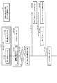
- FIG. 1 is a diagram illustrating a basic configuration example of a communication system according to each embodiment.
- FIG. 2 is a block diagram showing a functional configuration example of the client device and the server device according to each embodiment.
- FIG. 3 is a block diagram showing a functional configuration example of the communication control device on the client side and the communication control device on the server side according to each embodiment.
- FIG. 4 is a diagram showing a hardware configuration example of an IC card as a configuration example of an authentication unit in the communication control device according to each embodiment.
- FIG. 5 is a block diagram showing a functional configuration example of a C card as a configuration example of an authentication unit in the communication control device according to each embodiment.
- FIG. 6 is a block diagram showing a functional configuration example in the communication control management device according to each embodiment.
- FIG. 1 is a diagram illustrating a basic configuration example of a communication system according to each embodiment.
- FIG. 2 is a block diagram showing a functional configuration example of the client device and the server device according to each embodiment.
- FIG. 7 is a sequence showing an example of processing performed by the communication system shown in FIG.
- FIG. 8 is a diagram showing a first configuration example of the communication system according to the first embodiment.
- FIG. 9 is a block diagram showing a configuration example of the communication control device in the first configuration example of the communication system according to the first embodiment.
- FIG. 10 is a sequence for explaining an operation example of the communication system according to the first configuration example of the first embodiment.
- FIG. 11 is a diagram illustrating a second configuration example of the communication system according to the first embodiment.
- FIG. 12 is a block diagram showing a configuration example of a communication control device in a second configuration example of the communication system according to the first embodiment.
- FIG. 13 is a sequence for explaining an operation example of the communication system according to the second configuration example of the first embodiment.
- FIG. 14 is a diagram illustrating a configuration example of a communication system according to the second embodiment.
- FIG. 15 is a block diagram showing a configuration example of the communication control device in the configuration example of the communication system according to the second embodiment.
- FIG. 16 is a flowchart for explaining an operation example of the distributed controller in the communication system according to the second embodiment.
- FIG. 17 is a block diagram showing a configuration example of a communication system according to the third embodiment.
- FIG. 18 is a sequence for explaining a first operation example of the communication system according to the third embodiment.
- FIG. 19 is a sequence for explaining the second operation example of the communication system according to the third embodiment.
- FIG. 20 is a sequence for explaining the first operation example of the communication system according to the fourth embodiment.
- FIG. 21 is a sequence for explaining the second operation example of the communication system according to the fourth embodiment.
- FIG. 22 is a sequence for explaining the third operation example of the communication system according to the fourth embodiment.
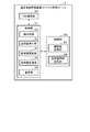
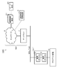
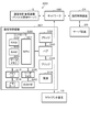
- FIG. 1 is a diagram showing a configuration example of a communication system 1 having a configuration that is a base of the communication system according to each embodiment.
- the communication system 1 includes a client device 10 (10-1 to 10-N), a server device 20, and a communication control device 30 (30-1 to 30-N) on the client side (“first communication control device”).
- first communication control device An example
- server-side communication control device 31 an example of a “first communication control device”
- a communication control management device 5 an example of a “private certificate authority”
- network 6 and the gateway 7 that connects the network 6 to the client device 10 and the like are collectively referred to as “network NW”.
- the client device 10 connects to the network NW via the communication control device 30 on the client side.
- the server device 20 connects to the network NW via the communication control device 31 on the server side. The details of the configurations of the client device 10 and the server device 20 will be described later.
- the communication control device 30 on the client side is connected between the client device 10 and the network NW, and mediates communication between the client device 10 and the server device 20.
- the communication control device 30 on the client side acquires data transmitted to the server device 20 by the client device 10, and outputs the acquired data to the server device 20.
- the communication control device 30 on the client side transmits data to the server device 20
- the data acquired from the client device 10 is encrypted, and the encrypted data is transmitted to the server device 20.
- the communication control device 30 on the client side acquires data transmitted to the client device 10 by the server device 20, and outputs the acquired data to the client device 10.
- the data acquired by the communication control device 30 on the client side is encrypted data.
- the communication control device 30 on the client side outputs data to the client device 10, it decodes the data acquired from the server device 20 via the communication control device 31 on the server side, and outputs the decoded data to the client device 10. To do.
- the communication control device 31 on the server side is connected between the server device 20 and the network NW, and mediates communication between the client device 10 and the server device 20.
- the communication control device 31 on the server side acquires data transmitted to the client device 10 by the server device 20, and transmits the acquired data to the client device 10.
- the communication control device 31 on the server side transmits data to the client device 10
- the data acquired from the server device 20 is encrypted, and the encrypted data is transmitted to the client device 10.
- the communication control device 31 on the server side acquires the data transmitted to the server device 20 by the client device 10, and outputs the acquired data to the server device 20.
- the data acquired by the communication control device 31 on the server side is encrypted data.
- the communication control device 31 on the server side outputs data to the server device 20, it decodes the data acquired from the client device 10 via the communication control device 30 on the client side, and outputs the decoded data to the server device 20. To do.
- Data encryption performed by the communication control device 30 on the client side and the communication control device 31 on the server side is performed by, for example, the SSL (Secure Socket Layer)/TLS (Transport Layer Security) protocol.
- the communication control device 30 on the client side and the communication control device 31 on the server side for example, by combining the SSL/TLS protocol with HTTP, encrypts the data included in the HTTP to improve security (HTTPS Secure). ).
- the data encryption performed by the communication control device 30 on the client side and the communication control device 31 on the server side is not limited to HTTP being HTTPS.
- the client-side communication control device 30 and the server-side communication control device 31 may be replaced with a secure communication protocol with improved safety by combining the SSL/TLS protocol with various communication protocols.
- the communication control device 30 on the client side and the communication control device 31 on the server side may replace FTP (File Transfer Protocol) with FTPS (FTP Secure).
- data encrypted by the communication control device 30 on the client side or the communication control device 31 on the server side is output to the network NW.
- the data flowing through the network NW in the communication system 1 is encrypted data. Therefore, the risk that the data transmitted / received on the network NW is maliciously accessed from the outside and the data is eavesdropped is avoided, and the safety is improved.
- the data eavesdropping referred to here means an "act of eavesdropping on data" or an "act of extracting data”.
- the communication control management device 5 is a communication management server for managing communication using the communication control device on the client side and the communication control device on the server side. For example, the communication control management device 5 issues a client certificate and a private key to the communication control device 30 on the client side. In the configuration example shown in FIG. 1, the communication control management device 5 issues a client certificate and a private key stored in an IC card mounted on the communication control device 30 on the client side. Further, the communication control management device 5 transmits the client certificate to be stored in the IC card and the private key to the communication control device 30 on the client side in which the IC card is mounted via the network NW.
- the communication control management device 5 issues a server certificate and a private key to the communication control device 31 on the server side.
- the communication control management device 5 issues a server certificate and a private key stored in the IC card.
- the communication control management device 5 transmits the server certificate and the private key stored in the IC card to the communication control device 31 on the server side in which the IC card is mounted via the network NW.
- the client certificate, the server certificate, and the private key are used to determine a common key (session key) used when the client-side communication control device 30 and the server-side communication control device 31 perform encrypted communication. It is necessary information for.
- the client device 10 and the server device 20 are components (components) that construct a social infrastructure system, for example.
- Social infrastructure is equipment necessary for preparing social infrastructure such as road transportation network, power generation equipment, distribution power equipment, water treatment equipment, gas distribution equipment, and the like.
- the social infrastructure system is, for example, a mechanism for stably operating the social infrastructure by monitoring the social infrastructure, grasping changes in the situation, and responding to the changes.
- the client device 10 and the server device are components of a monitoring system that monitors roads and public facilities will be described as an example.
- the client device 10 is a device (network monitoring camera) that transmits the imaged data in which the road condition and the like are imaged through the network NW.
- the server device 20 is a device that receives the imaging data transmitted by the client device 10 via the network NW.
- the client device 10 and the server device 20 are not limited to the components of the monitoring system.
- the client device 10 and the server device may be components of a system that monitors the power status of power generation equipment or delivery power equipment, a system that acquires the delivery status at a distribution center, or equipment at a factory or research institute. It may be a component such as a system for acquiring the operating status of.
- FIG. 2 is a block diagram showing a functional configuration example of the client device 10 and the server device 20 shown in FIG.
- the client device 10 includes a NW (network) communication unit 11, a client control unit 12, and an imaging unit 13.
- the NW communication unit 11 is, for example, an Ethernet (registered trademark) port of the client device 10.
- the NW communication unit 11 is connected to the communication control device 30 on the client side, and outputs the data transmitted from the client device 10 to the server device 20 to the communication control device 30 on the client side.
- the NW communication unit 11 corresponds to a functional unit that is connected to the network NW and communicates with the server device 20 via the network NW in a conventional system.
- the client control unit 12 is, for example, a processor including a CPU and the like, and controls the client device 10 in an integrated manner.
- the client control unit 12 causes the imaging unit 13 to start or stop imaging according to the control from the server device 20, and sets imaging conditions such as the direction of the camera to be imaged with respect to the imaging unit 13 and the magnification at the time of imaging. Set it.
- the imaging unit 13 captures a landscape at a predetermined location according to the instructions of the client control unit 12.
- the imaging unit 13 outputs the captured data (imaging data) to the client control unit 12.
- the server device 20 includes an NW (network) communication unit 21, a server control unit 22, and an imaging data storage unit 23.
- the NW communication unit 21 is, for example, an Ethernet (registered trademark) port of the server device 20.
- the NW communication unit 21 is connected to the server-side communication control device 31 and outputs the data transmitted from the server device 20 to the client device 10 to the server-side communication control device 31. If it is a conventional system, the NW communication unit 21 corresponds to a functional unit that is connected to the network NW and communicates with the client device 10 via the network NW.
- the server control unit 22 is, for example, a processor including a CPU and controls the server device 20 in a centralized manner.
- the server control unit 22 stores, for example, the imaged data captured by the client device 10 in the imaged data storage unit 23.
- the imaging data storage unit 23 stores the imaging data according to the instruction of the server control unit 22.
- the unencrypted information (so-called plaintext) output to the network NW by the client device 10 or the server device 20 flows through the network NW.
- the client device 10 encrypts the imaged data and outputs it to the network NW.
- the client control unit 12 of the client device 10 encrypts the imaging data and outputs the encrypted imaging data to the network NW.
- a processor such as a CPU provided in a surveillance camera is generally used for the purpose of compressing or encoding image data, it is further subjected to processing for encryption. In many cases, it does not have just the resources. In such a case, the CPU originally possessed by the client control unit 12 cannot encrypt the captured data.
- the client control unit 12 encrypts the imaging data, it is necessary to change or replace the hardware configuration of the client control unit 12, such as mounting a processor for encrypting the imaging data on the client control unit 12. It is possible that Since the client device 10 is a component that constitutes social infrastructure such as a surveillance camera, it is not easy to change or replace the hardware configuration. In view of such circumstances, it is desirable that the imaged data is encrypted and output to the network NW without changing the client device 10.
- the communication control device 30 on the client side connected between the client device 10 and the network NW encrypts the data transmitted by the client device 10 and outputs the data to the network NW.
- the server-side communication control device 31 connected between the server device 20 and the network NW encrypts the control data transmitted by the server device 20 and outputs the encrypted control data to the network NW.
- FIG. 3 is a block diagram showing a functional configuration example of the communication control device 30 on the client side and the communication control device 31 on the server side shown in FIG.
- the functional configurations of the communication control device 30 on the client side and the communication control device 31 on the server side are the same. Therefore, in the following, the configuration of one (for example, the communication control device 30 on the client side) will be described, and the configuration of the other (for example, the communication control device 31 on the server side) will be omitted. Further, in the following, when the communication control device 30 on the client side and the communication control device 31 on the server side are not distinguished, they are simply referred to as the communication control device 30 (31) or the like.
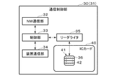
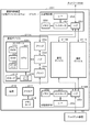
- the communication control device 30 (31) includes a NW (network) communication unit 32, a control unit 33, a device communication unit 34, a reader / writer 35, and an IC card 40.
- the IC card 40 is an example of an “authentication unit”.
- the authentication unit is not limited to that realized by the reader / writer 35 and the IC card 40.
- the authentication unit may be realized by the control unit 33 or may be realized by a processing circuit for authentication processing.
- the NW communication unit 32 is connected to the network NW and communicates with the other communication control device 30 (31) via the network NW.
- the control unit 33 is, for example, a processor including a CPU and controls the communication control device 30 (31) in a centralized manner.
- the control unit 33 transmits a command to the IC card 40 and receives a response from the IC card 40, for example, via the reader / writer 35. Further, the control unit 33 transmits information based on the response received from the IC card 40 to the other communication control device 30 (31) via the NW communication unit 32.
- the control unit 33 also transmits a command to the IC card 40 based on the information received from the other communication control device 30 (31) via the NW communication unit 32.
- the device communication unit 34 is connected to the device (the client device 10 or the server device 20) and communicates with the device. Specifically, the device communication unit 34 of the communication control device 30 on the client side is connected to the client device 10, acquires imaging data from the client device 10, and outputs the decrypted control data to the client device 10. .. Further, the device communication unit 34 of the communication control device 31 on the server side is connected to the server device 20, acquires the control data from the server device 20, and outputs the decoded imaging data to the server device 20.
- the reader / writer 35 connects to the IC card 40 via the contact unit 36 and communicates with the IC card 40.
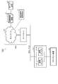
- the IC card 40 is formed by mounting the IC module 41 on, for example, a plastic card base material. That is, the IC card 40 includes an IC module 41 and a card base material in which the IC module 41 is embedded.
- the IC card 40 is detachably attached to the communication control device 30 (31) and can communicate with the communication control device 30 (31) via the contact portion 36.
- the IC card 40 receives a command (process request) transmitted by the communication control device 30 (31) via the contact unit 36, and executes a process (command process) according to the received command. Then, the IC card 40 transmits a response (processing response), which is the execution result of the command processing, to the communication control device 30 (31) via the contact unit 36.
- the IC module 41 includes a contact portion 36 and an IC chip 42.
- the contact portion 36 has terminals for various signals necessary for the IC card 40 to operate.
- the terminals of various signals are terminals that receive power supply voltage, clock signal, reset signal, etc. from the communication control device 30 (31), and serial data input for communicating with the communication control device 30 (31). It has an output terminal (SIO terminal).
- the IC chip 42 is, for example, an LSI (Large Scale Integration) such as a one-chip microprocessor.
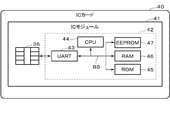
- FIG. 4 is a diagram showing a hardware configuration example of the IC card 40 shown in FIG.
- the IC card 40 includes an IC module 41 including a contact portion 36 and an IC chip 42.
- the IC chip 42 includes a UART (Universal Asynchronous Receiver Transmitter) 43, a CPU 44, a ROM (Read Only Memory) 45, a RAM (Random Access Memory) 46, and an EEPROM (registered trademark) (Electrically Erasable Programmable ROM) 47.
- UART Universal Asynchronous Receiver Transmitter
- CPU 44 central processing unit
- ROM Read Only Memory
- RAM Random Access Memory
- EEPROM registered trademark
- each configuration (43 to 47) is connected via an internal bus BS.
- the UART 43 performs serial data communication with the communication control device 30 (31) via the SIO terminal described above.
- the UART 43 outputs data (for example, 1-byte data) obtained by converting the serial data signal received via the SIO terminal to parallel to the internal bus BS. Further, the UART 43 serially converts the data acquired via the internal bus BS and outputs the data to the communication control device 30 (31) via the SIO terminal.
- the UART 43 receives a command from the communication control device 30 (31) via the SIO terminal, for example. Further, the UART 43 transmits a response to the communication control device 30 (31) via the SIO terminal.
- the CPU 44 executes a program stored in the ROM 45 or the EEPROM 47 to perform various processes on the IC card 40.
- the CPU 44 executes command processing according to the command received by the UART 43, for example, via the contact unit 36.
- the ROM 45 is, for example, a non-volatile memory such as a mask ROM, and stores data such as a program for executing various processes of the IC card 40 and a command table.
- the RAM 46 is, for example, a volatile memory such as an SRAM (Static RAM), and temporarily stores data used when performing various processes of the IC card 40.
- the EEPROM 47 is, for example, an electrically rewritable nonvolatile memory.
- the EEPROM 47 stores various data used by the IC card 40.
- the EEPROM 47 stores information used for various services (applications) using the IC card 40, for example.
- FIG. 5 is a block diagram showing a functional configuration example of the IC card 40 shown in FIG.
- the IC card 40 includes a communication unit 50, a control unit 51, and a storage unit 54.
- each unit of the IC card 40 shown in FIG. 5 is realized by using the hardware of the IC card 40 shown in FIG.
- the communication unit 50 is realized by, for example, the UART 43, the CPU 44, and a program stored in the ROM 45, and transmits and receives commands and responses to and from the communication control device 30 (31) via the contact unit 36, for example. I do. That is, the communication unit 50 receives a command (processing request) requesting a predetermined process from the communication control device 30 (31), and transmits a response (processing response) to the command to the communication control device 30 (31). The communication unit 50 stores the received data received from the communication control device 30 (31) via the UART 43 in the RAM 46. Further, the communication unit 50 transmits the transmission data stored in the RAM 46 to the communication control device 30 (31) via the UART 43.
- the control unit 51 is realized by, for example, the CPU 44, the RAM 45, the ROM 46, or the EEPROM 47, and integrally controls the IC card 40.
- the control unit 51 includes a command processing unit 52 and an encryption/decryption unit 53.
- the process performed by the command processing unit 52 is an example of “authentication process”.
- the process performed by the encryption / decryption unit 53 is an example of the “encryption / decryption process”.
- the command processing unit 52 executes various command processing.
- the command processing unit 52 performs an SSL/TLS handshake, for example, as command processing for requesting an HTTPS request described later.
- SSL/TLS handshake key information and the like necessary for encrypted communication are exchanged, and mutual authentication with a communication destination device is performed.
- the mutual authentication is an authentication process in which the communication control device 30 on the client side and the communication control device 31 on the server side mutually confirm that they are properly authenticated before communication. is there.
- the encryption/decryption unit 53 executes a process of encrypting the data and a process of decrypting the encrypted data.
- the encryption/decryption unit 53 encrypts the data output by the device (the client device 10 or the server device 20) acquired via the communication unit 50. Further, the encryption / decryption unit 53 decrypts the encrypted data from the network NW acquired via the communication unit 50.
- the storage unit 54 is, for example, a storage unit composed of an EEPROM 47, and includes a certificate information storage unit 55 and a secret information storage unit 56.
- the certificate information storage unit 55 stores the certificate issued by the communication control management device 5 for the device (the client device 10 or the server device 20).
- the certificate information storage unit 55 of the IC card 40 mounted on the communication control device 30 on the client side stores information indicating the client certificate.
- information indicating the server certificate is stored in the certificate information storage unit 55 of the IC card 40 attached to the communication control device 31 on the server side.
- the secret information storage unit 56 stores the secret key for the device (client device 10 or server device 20) issued by the communication control management device 5. Specifically, the secret information storage unit 56 of the IC card 40 mounted on the client-side communication control device 30 stores information indicating the secret key issued to the client-side communication control device 30. .. The certificate information storage unit 55 of the IC card 40 mounted on the server-side communication control device 31 stores information indicating the private key issued to the server-side communication control device 31.
- FIG. 6 is a block diagram showing a configuration example of the communication control management device 5 shown in FIG.
- the communication control management device 5 includes, for example, a NW (network) communication unit 60, a control unit 61, and a storage unit 66.
- the NW communication unit 60 is connected to the network NW and communicates with the communication control device 30 (31) via the network NW.
- the control unit 61 includes a processor such as a CPU, for example.
- the control unit 61 realizes various processes by the processor executing programs.
- the control unit 61 comprehensively controls the communication control management device 5. Further, the control unit 61 mainly operates as a private certification authority that recognizes the validity of the communication control device 30 (31).
- the control unit 61 functions as a key generation unit 62, a certificate issuing unit 63, a certificate updating unit 64, a certificate management unit 65, and a management unit 69 when the processor executes a program. Execute the process to realize.
- the key generation unit 62 issues a private key corresponding to the public key included in the certificate described later, based on the authentication application from the communication control device 30 (31), for example.
- the certificate issuing unit 63 issues a certificate that recognizes the validity of the communication control device 30 (31), for example, based on the certification application from the communication control device 30 (31).
- the certificate includes a public key and information indicating the owner of the communication control device 30 (31).
- the certificate renewal unit 64 renews the certificate by setting a new expiration date for the certificate whose expiration date has passed.
- the certificate renewal unit 64 issues, for example, a certificate with an extended expiration date of the certificate issued to the communication control device 30 (31) based on the renewal application from the communication control device 30 (31). Then, the issued certificate is transmitted to the communication control device 30 (31).
- Information indicating the issued certificate is received by the communication control device 30 (31) and is stored in the certificate information storage unit 405 of the IC card 40 of the communication control device 30 (31). ) Certificate is extended.
- the certificate management unit 65 manages the certificates that have already been issued.
- the certificate management unit 65 for example, when the IC card 40 mounted on the communication control device 30 (31) is tampered with, stolen, or the like, and mutual validity is not proved in mutual authentication, the communication control device 30 (31). Perform the process of invalidating the certificate issued to.
- the certificate management unit 65 receives a certificate issued to the communication control device 30 (31) and other communication devices based on an inquiry from the communication control device 30 (31) by the certificate management unit 65. You may make it respond whether it was issued. Further, the certificate management unit 65 may periodically check whether the issued certificate is used by the legitimate communication control device 30 (31).
- the management unit 69 manages the communication control device 30 (31). For example, the management unit 69 remotely controls the mutual authentication performed by the communication control device 30 (31) via the network NW.
- the storage unit 66 includes, for example, a key information storage area 67 and a certificate information storage area 68.
- the key information storage area 67 stores, for example, information indicating an already issued public key or a private key.
- the certificate information storage area 68 stores, for example, information indicating a certificate that has already been issued.
- the key information storage area 67 and the certificate information storage area 68 are referred to, for example, when the key generation unit 62 issues a private key and when the certificate issuing unit 63 issues a certificate. Further, in the key information storage area 67, information indicating a private key issued by the key generation unit 62 is stored. Further, in the certificate information storage area 68, information indicating a certificate issued by the certificate issuing unit 63 is stored.
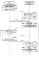
- FIG. 7 is a sequence chart showing an example of processing performed by the communication system 1.
- the client device 10 When transmitting the imaging data to the server device 20, the client device 10 first transmits an HTTP request to the server device 20 (step S1).
- the HTTP request transmitted by the client device 10 is acquired by the communication control device 30 on the client side (step S2).
- the client-side communication control device 30 acquires the HTTP request transmitted by the client device 10, the client-side communication control device 30 transmits an HTTPS request (Client Hello) to the server-side communication control device 31 (step S3). As a result, a handshake between the communication control device 30 on the client side and the communication control device 31 on the server side is started (step S4).
- the Client Hello transmitted by the communication control device 30 on the client side includes, for example, information indicating the version of TLS and a list of encryption methods and algorithms used for communication.
- the server-side communication control device 31 transmits an HTTPS response (Server Hello) to the client-side communication control device 30 as a response to the Client Hello.
- the Server Hello transmitted by the communication control device 31 on the server side includes, for example, information selected by the server device 20 from the options presented by the Client Hello. In other words, the communication control device 31 on the server side selects a presentation from the communication control device 30 on the client side, thereby determining a specific encryption algorithm in communication.
- the communication control device 31 on the server side sends necessary information to the common key used for encrypted communication.
- the information required for the common key includes, for example, information indicating the public key issued to the server device 20 and its certificate, and information requesting that the public key of the client device 10 and its certificate be sent. Be done.
- the communication control device 30 on the client side sends the communication control device 31 on the server side the information necessary for the public key issued to the own device, its certificate, and the common key used for encrypted communication.
- Mutual authentication between the communication control device 30 on the client side and the communication control device 31 on the server side is performed, for example, as follows.
- the communication control device 30 on the client side generates a signature from the Server Hello received so far and sends it to the communication control device 31 on the server side.
- the server-side communication control device 31 verifies the signature received from the client-side communication control device 30 based on the certificate received from the client-side communication control device 30. If the verification is successful, the server-side communication control device 31 determines that the certificate definitely belongs to the client-side communication control device 30. Further, the server-side communication control device 31 generates a signature from the Client Hello received so far and sends it to the client-side communication control device 30.
- the communication control device 30 on the client side verifies the signature received from the communication control device 31 on the server side based on the certificate received from the communication control device 31 on the server side. If the verification is successful, the communication control device 30 on the client side determines that the certificate is definitely that of the communication control device 31 on the server side.
- the client-side communication control device 30 and the server-side communication control device 31 are used for encryption, respectively. Generate and exchange a common key.
- the server-side communication control device 31 terminates the handshake if the public key and its certificate sent from the client-side communication control device 30 are certificates that are acceptable to the server-side communication control device 31.
- the communication control device 31 on the server side transmits an HTTP request to the server device 20 (step S5).
- the HTTP request is an HTTP request transmitted from the client device 10 in step S1.
- the HTTP request transmitted by the communication control device 31 on the server side is received by the server device 20 (step S6).
- the server device 20 recognizes that the HTTP request has been requested from the client device 10. Therefore, the server device 20 responds with an HTTP response to the client device 10 (step S7).
- the HTTP response transmitted by the server device 20 is acquired by the communication control device 31 on the server side (step S8).
- the communication control device 31 on the server side encrypts the acquired HTTP response from the server device 20 using the common key determined in the handshake of step S4 (step S9).
- the HTTP response encrypted by the communication control device 31 on the server side is received by the communication control device 30 on the client side via the network NW (step S10).
- the communication control device 30 on the client side decrypts the received HTTP response using the common key (step S11).
- the HTTP response decrypted by the communication control device 30 on the client side is acquired by the client device 10 (step S12).
- the client device 10 receives the decrypted HTTP response (step S13). At this time, the client device 10 recognizes that the HTTP response is returned from the server device 20. Therefore, the client device 10 transmits the imaging data to the server device 20 (step S14).
- the image pickup data transmitted by the client device 10 is acquired by the communication control device 30 on the client side (step S15).
- the communication control device 30 on the client side encrypts the imaging data transmitted by the client device 10 using a common key (step S16).
- the imaged data encrypted by the communication control device 30 on the client side is received by the communication control device 31 on the server side via the network NW (step S17).
- the communication control device 31 on the server side decrypts the received imaging data using the common key (step S18).
- the image pickup data decrypted by the communication control device 31 on the server side is acquired by the server device 20 (step S19).
- the server device 20 receives the decrypted imaging data (step S20). At this time, the server device 20 recognizes that the imaging data from the client device 10 has been received.
- the communication control device 30 on the client side communicates with the communication destination. Do not allow communication. Specifically, the communication control device 30 on the client side does not output the information transmitted from the communication destination to the client device 10. This is because if the mutual authentication is not performed correctly, the communication destination may be an unauthorized communication device disguised as the communication control device 31 on the server side. In this case, the communication control device 30 on the client side may transmit, for example, a communication record when mutual authentication is not performed correctly to the communication control management device 5. As a result, the communication control management device 5 can acquire a communication record when mutual authentication is not correctly performed, and grasp the pattern or frequency of unauthorized communication with the client-side communication control device 30 under management. By doing so, it is possible to monitor network abnormalities.
- the communication control device 30 on the client side is a communication destination based on a destination list indicating information of a communication device that allows communication to the client device 10 instead of mutual authentication in the handshake performed in step S4 of the above flowchart. It may be determined whether or not to allow communication with.
- the information about the communication device shown in the destination list is, for example, a URL (Uniform Resource Locator).
- URL Uniform Resource Locator
- control unit 33 may update the destination list.
- the control unit 33 stores, for example, a URL of a communication destination permitted to communicate with the client device 10 and a communication destination URL not permitted to communicate with the client device 10 for a certain period. Then, the control unit 33 updates the destination list by, for example, re-registering the URL of the communication destination with which communication has been performed for a certain period of time among the URLs registered in the destination list.
- the communication control device 30 on the client side may transmit the communication destination URL that is permitted to communicate and the communication destination URL that is not permitted to communicate to the communication control management device 5 for a certain period of time.
- the communication control management device 5 may update the destination list based on the communication destination URL that has communicated with the communication control device 30 on the client side.
- the communication control management device 5 it is possible to collectively manage the communication devices that communicate with the communication control device 30 on the client side under the control of the communication control management device 5.
- the client-side communication control device 30 verifies whether or not the content of the information (for example, the firmware update program) transmitted to the client device 10 after the handshake performed in step S4 is established is correct. You may do it.
- the control unit 33 of the client-side communication control device 30 verifies using a verification key (verification key).
- the communication control management device 5 may transmit the verification key to, for example, the communication control device 30 on the client side and the communication control device 31 on the server side.
- the communication control device 31 on the server side generates a hash value from the information (plain text) transmitted to the client device 10, and encrypts the generated hash value with the verification key. Then, the communication control device 31 on the server side further encrypts the plaintext and the encrypted hash value with a secret key, and sends the encrypted hash value to the client device 10. Further, the communication control device 30 on the client side decrypts the information using the common key, and acquires the plaintext and the encrypted hash value.
- the communication control device 30 on the client side generates a hash value from the acquired plaintext and decrypts the encrypted hash value with the verification key.
- the communication control device 30 on the client side determines that the information transmitted to the client device 10 is correct. In this case, the communication control device 30 on the client side outputs the decrypted information (plain text) to the client device 10.
- the communication control device 30 on the client side determines that the information transmitted to the client device 10 is the server device 20 or the communication control on the server side. It is determined that there is a possibility that the information is unauthorized information transmitted from an unauthorized communication device that is disguised as the device 31. In this case, the client-side communication control device 30 does not output the decrypted information (plain text) to the client device 10.
- the client device 10 can receive only the information that has been verified to have the correct content. Further, normally, it is considered that the client device 10 determines whether or not the content of the update program is correct when the firmware is updated. However, instead of the client device 10, the communication control device 31 on the server side instructs the client device 10 to do so. By verifying the content of the transmitted information, the processing load on the client device 10 can be reduced.
- a control device 31 is provided.
- the communication control device 30 on the client side encrypts the information from the client device 10 and transmits it to the communication control device 31 on the server side via the network NW, and the information from the network NW (the server encrypted by the communication control device 31) is transmitted.
- Information from the device 20) is decoded and transmitted to the client device 10.
- the communication control device 31 on the server side encrypts the information from the server device 20 and transmits it to the communication control device 30 on the client side via the network NW, and the information from the network NW (the client encrypted by the communication control device 30 is transmitted.
- Information from the device) is decrypted and transmitted to the server device 20.
- the communication system 1 can improve the safety of the social infrastructure system without changing the social infrastructure system.
- the HTTP protocol imaging data (so-called plain text) transmitted from the client device 10 to the server device 20 is combined with the SSL/TLS protocol by the communication control device 30 on the client side, for example, to improve security. This is because it is replaced by HTTPS.
- the control data transmitted to the server device 20 or the client device 10 is encrypted, but is decrypted by the communication control device 30 on the client side and received by the client device 10, so that the client device 10 Since it is not necessary to perform the decryption process on the existing device, the existing device can be used as it is without being changed.
- the communication control device 30 on the client side and the communication control device 31 on the server side perform mutual authentication, it is possible to improve safety as compared with the case of performing authentication in only one direction. ..
- a valid client certificate is issued and managed for the unspecified number of client terminals. It is not realistic to continue.
- the communication control device 30 on the client side and the communication control device 31 on the server side can perform mutual authentication, and the security can be improved.
- a client terminal that does not have a client certificate may be required to enter an ID and password issued by the server device in order to communicate with the server device.
- password authentication in order to maintain security, a long character string combining letters and numbers may be required for the password, or the password may be changed regularly.
- management becomes troublesome, and there are cases where passwords are leaked, such as when the password is written in a memo or recorded in a web browser.
- the communication control device 30 on the client side since the communication control device 30 on the client side has the client certificate, mutual authentication can be reliably performed with the server device 20. Therefore, password authentication becomes unnecessary. Therefore, the trouble of entering the password and the trouble of periodically changing and managing the password are eliminated, and the convenience of the user is improved. That is, safety can be maintained without imposing a burden on the user.
- the client device 10 and the server device 20 are illegal because mutual authentication is performed between the client device 10 and the server device 20 via the communication control device 30 (31). Will not be hijacked. That is, in the communication system 1, it is possible to take measures against ransomware.
- the terminal also called a stray device
- the terminal will be illegally hijacked and used as an illegal terminal that attacks malware etc.
- mutual authentication is performed between the client device 10 and the server device 20 via the communication control device 30 (31), so that the administrator inside the network NW can Even if an absent terminal is illegally hijacked and used for an attack, it is possible to prevent infection with malware or the like.
- the server device 20 is connected to the communication control device 31 on the server side, and the authentication process is not performed inside the server device 20. Therefore, it is not necessary to hold a certificate or the like inside the server device 20, and it becomes clear that the server device 20 connected to the server-side communication control device 31 is under the control of the communication control management device 5.
- the server device 20 already has a functional unit corresponding to the communication control device 31 on the server side, the communication control device 31 on the server side is not necessarily physically connected between the server device 20 and the network NW. You don't have to.
- the functional unit corresponding to the communication control device 31 on the server side originally possessed by the server device 20 performs the authentication process with the communication control device 30 on the client side.
- control unit 401 of the IC card 40 is made to perform at least one of mutual authentication and encryption / decryption processing. Therefore, the device cost of the communication control device 30 (31) can be suppressed.
- the IC card 40 mounted on the communication control device 30 (31) performs at least one of mutual authentication and encryption / decryption processing.
- the configuration for performing mutual authentication and encryption/decryption processing is not limited to the IC card.
- the IC card 40 described above has a storage function for storing a private key and a client certificate (or a server certificate), and a processing function for performing at least one of mutual authentication and encryption / decryption processing.
- the SIM card may be a SIM card having an IC chip mounted thereon, or the card form may not be adopted.
- the IC card 40 of the communication control device 30 on the client side is detachably attached to the communication control device 30 on the client side.
- the IC card 40 and the communication control device 30 on the client side can be separated. Therefore, when exchanging either one, the one device may be exchanged.
- the IC card 40 and the communication control device 30 on the client side are integrated, when the part corresponding to the IC card 40 is replaced, the entire communication control device 30 on the client side must be replaced.
- the communication system 1 further includes a communication control management device 5, and the communication control management device 5 stores a private key stored in an IC card 40 mounted on the communication control device 30 on the client side and a client certificate on the client side.
- the secret key stored in the IC card 40 mounted on the communication control device 31 on the server side and the server certificate are transmitted to the communication control device 31 on the server side.
- the communication system 1 can perform a handshake and determine a common key by using a legitimate secret key and certificate issued by the communication control management device 5, and in addition to the above-described effect, the social key The safety of the infrastructure system can be further improved.
- the configuration of the communication system 1 is not limited to the above-mentioned example.
- the communication control device 30 (31) may use an HSM (Hardware Security Module) that realizes the functions of the communication control device 30 (31) by hardware based on the processing load. That is, the communication control device 30 (31) is not limited to the configuration in which an IC card is mounted as long as secure processing is possible, and an IC chip or an IC module that can realize the function of the communication control device 30 (31) is used. It may be the configuration that was used.
- HSM Hardware Security Module
- secure communication using the SSL/TLS protocol may be constantly performed, or whether communication using the SSL/TLS protocol may be selectable. Further, only the communication in one direction of the bidirectional communication between the client device 10 and the server device 20 may be the communication using the SSL / HTTPS protocol. Further, secure communication using the SSL / HTTPS protocol may be performed at all times, or it may be possible to select whether or not to perform communication using the SSL / HTTPS protocol.
- communication using the SSL/TLS protocol may be constantly performed to store unauthorized access to the client device 10 and the server device 20.
- a record of unauthorized access may be transmitted to the communication control management device 5.
- the communication control management device 5 can recognize whether or not there is an unauthorized access, and can detect a warning sign before a large-scale attack on the entire system is started and take countermeasures.
- the communication control device 30 (31) periodically confirms whether or not the connection with the client device 10 or the server device 20 to which the own device is connected is maintained. May be. In this case, information indicating the connection status may be transmitted to the communication control management device 5.
- the communication control management device 5 determines that the communication control device 30 (31) is disconnected from the client device 10 or the server device 20 when the information indicating the connection state cannot be received from the communication control device 30 (31), The disconnected communication control device 30 (31) is invalidated. By doing so, the communication control management device 5 prevents the disconnected communication control device 30 (31) from being connected to an unauthorized device and being misused for spoofing.
- the IC card 40 mounted on the communication control device 30 (31) may be equipped with a highly tamper-resistant chip called a secure element that has acquired CC (Common Criteria/ISO15408) certification. .. By using this chip to store a certificate containing a private key and a public key, extremely high security can be maintained.
- CC Common Criteria/ISO15408
- the program of the client device 10 may be updated from the server device 20, the communication control management device 5, or the like via the communication control device 30 (31).
- the function of the client device 10 can be safely updated.
- the firmware transmitted from the server device 20 is, for example, signed by the server device 20 encrypted by the communication control device 31 on the server side. Granted.
- the client device 10 can determine that the transmitted firmware is definitely the firmware transmitted from the server device 20 by decoding the signature by the communication control device 30 on the client side.
- the client device 10 is erroneously based on the unauthorized firmware. It is possible to exclude that updates are made.
- the firmware can be safely updated from the server device 20, the communication control management device 5, and the like to the client device 10. It is also possible to reduce the work cost as compared with the case where the firmware is updated by physically moving the plurality of client devices 10 to the place where each client device 10 is installed.
- the client device 10 may be started or stopped from the server device 20, the communication control management device 5, or the like via the communication control device 30 (31). By starting or stopping (remote activation) via the communication control device 30 (31), the function of the client device 10 can be safely updated, and secure remote control can be realized.
- At least one of the client device 10 and the server device 20 may be a device that performs wireless communication via a wireless LAN or the like.
- the communication control device 30 on the client side has a wireless communication function and encrypts the data transmitted by the client device 10 and encrypts the data.
- the data is transmitted to the server device 20 by wireless communication.
- the communication control device 30 on the client side communicates with the communication control device 31 on the server side
- the communication destination of the communication control device 30 on the client side is limited to this.
- the communication control device 30-1 on the client side may communicate with the communication control device 30-2 on the client side.
- the communication control device 30-1 on the client side receives a signal to start communication from the communication control device 30-2 on the client side, it first performs mutual authentication with the communication control device 30-2 on the client side, and the client It is confirmed that the communication control device 30-2 on the side is a valid communication terminal.
- the communication control device 30-1 on the client side outputs the information received from the communication control device 30-2 on the client side to the client device 10.
- an authenticator to the transmitted data using encryption, it is possible to detect falsification of communication information and identify the sender. Therefore, in the communication system 1, in the communication between the communication control device 30 on the client side and the communication control device 31 on the server side and the communication between the communication control devices 30 on the client side, "from the correct partner" and "tampering" are performed. You can be assured that you will not "receive data.”
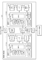
- FIG. 8 is a diagram showing a first configuration example of the communication system 100 according to the first embodiment.
- the communication control device 30 is replaced with the communication control device 101 in the system configuration shown in FIG.
- the communication control apparatus 101 has a plurality of communication devices 111A and 111B provided in parallel between the network NW and the client apparatus 10.
- each device other than the communication control device 101 in the communication system 100 can be realized by the same configuration as the device shown in FIG. Therefore, detailed description of configurations other than the communication control device 101 will be omitted below.
- the communication control device 31 may also be configured to include a plurality of communication devices provided in parallel between the network NW and the server device 20, similarly to the communication control device 101.
- FIG. 9 is a block diagram showing a configuration example of the communication control device 101 in the first configuration example of the communication system 100 according to the first embodiment.
- the communication control apparatus 101 has a first communication device 111A and a second communication device 111B arranged in parallel as a plurality of communication devices 111.
- the first communication device 111A and the second communication device 111B are connected in parallel between the hub 114 connected to the network NW side and the hub 115 connected to the client side.
- Each of the first communication device 111A and the second communication device 111B has a configuration that executes the same communication process as the communication control device 30 shown in FIG. 1 described above.
- the communication control device 101 has a power supply 116 and a memory I / F 117 shared by the first communication device 111A and the second communication device 111B.
- the power supply 116 is connected to an external power supply and supplies the power from the external power supply to the communication devices 111A and 111B.
- the memory I/F 117 is an interface for setting a memory device 118 such as a memory card.
- the memory I / F 117 is set with a memory device 118 that stores information applied to the communication devices 111A and 111B such as initial setting information.
- the memory device 118 set in the memory I / F 117 may store data (for example, log data) supplied from the communication devices 111A and 111B.
- the communication control device 101 may be realized as a system in which a plurality of communication devices having the same configuration as the communication control device 30 are arranged in parallel.
- each communication device may be configured to include a power supply, a memory I / F, and the like.
- the first communication device 111A and the second communication device 111B may be arranged in parallel between the network NW and the client device 10.
- the communication control device 101 may have a configuration in which the first communication device 111A and the second communication device 111B are provided with interfaces for connecting to the network NW and the client device 10, respectively, without providing the hubs 114 and 115. good.
- each communication control device 101 the first communication device 111A and the second communication device 111B are arranged in parallel between the network NW and the client device 10, and one of them is in the normal communication mode (first communication mode). Execute communication processing.
- the communication control device 101 realizes communication control between the network NW and the client device 10 by switching the communication devices 111A and 111B that communicate in the normal communication mode.
- the normal communication mode is assumed to be an operation mode in which communication involving encryption and decryption of transmission/reception data using a common key based on mutual authentication with the server-side communication control device 31 as described above is performed. .. Further, in the present embodiment, the communication control device 101 executes communication in the normal communication mode in the whitelist operation mode that allows communication with the destinations listed in the whitelist described later.
- the first communication device 111A and the second communication device 111B provided in parallel in the communication control device 101 may be realized by two independent software for communication processing.
- one communication device may be operated as two communication devices that are arranged in parallel and realized by two pieces of software.
- Each communication device 111 has a function of detecting its own failure, unauthorized access, malware infection, or the like. For example, the communication device 111 transmits, to the communication control management device (device management server) 5, information indicating a failure such as a failure, unauthorized access or malware infection, or a failure such as communication failure. Further, each communication device 111 switches the operation mode according to an instruction from the communication control management device 5. For example, each communication device 111 switches from the non-communication state to the normal communication mode or switches from the normal communication mode to the non-communication state in response to an instruction from the communication control management device 5.
- each communication device 111 (111A, 111B) has a controller 120, a bridge 132, a hub 133, a bridge 134, a reader/writer 135, and an IC card 140.
- the controller 120 controls the communication device 111.
- the controller 120 includes an MPU 121, a RAM 122, a SAM 123, a data memory 124, and the like.
- the MPU 121 is an example of a processor that controls the controller 120.
- the MPU 121 implements various processes by executing a program stored in the data memory 124 or the like.
- the controller 120 executes processes such as communication control, failure detection, communication failure detection, self-diagnosis, and log information collection when the MPU 121 executes a program.
- the controller 120 causes the MPU 121 to execute a program, thereby performing mutual authentication processing with the server-side communication control device 31, encryption processing of data transmitted from the client device 10 to the network NW, and client processing via the network NW. You may make it perform the decoding process etc. of the encrypted data transmitted to an apparatus. Further, the controller 120 may request the IC card 140 connected via the reader / writer 135 to perform at least one of mutual authentication processing, encryption processing, and decryption processing.
- the RAM 122 is a random access memory.
- the RAM 122 functions as a working memory that holds work data.
- the SAM 123 is a serial access memory.
- the data memory 124 is a rewritable nonvolatile memory.
- the data memory 124 stores programs and setting information.
- the data memory 124 stores a white list showing a list of destinations that are allowed to communicate.
- the controller 120 refers to the whitelist stored in the data memory 124 for communication. Execute. Further, the controller 120 may rewrite the white list in the data memory 124 in response to an instruction from the communication control management device 5.
- the communication device 111 may be put into a non-communication state by deleting all the destinations on the white list.
- the data memory 124 may store log information indicating the operating state of the communication device. The log information stored in the data memory 124 is sent to the communication control management device (device management server) 5 or used for self-diagnosis processing or the like.
- the bridges 132 and 134 function as a communication interface (communication unit). Bridges 132 and 134 are connected to controller 120 via hub 133. The bridge 132 executes communication on the network NW side in the communication device 111. The bridge 132 realizes communication as the NW communication unit 32 shown in FIG. The bridge 132 supplies the data received from the network NW to the controller 120 via the hub 133. Further, the bridge 134 sends the data encrypted by the controller 120 or the IC card 140 to the network NW.
- the bridge 134 executes communication on the client device 10 side in the communication device 111.
- the bridge 134 realizes communication as the device communication unit 34 shown in FIG.
- the bridge 134 supplies the data from the client device 10 to the controller 120 via the hub 133.
- the bridge 134 transmits the data obtained by decrypting the encrypted data from the network NW with the controller 110 or the IC card 140 to the client device 10.
- the reader/writer 135 and the IC card 140 correspond to the reader/writer 35 and the IC card 40 shown in FIG. 3 described above.
- the IC card 140 can be realized by having the same configuration as the IC card 40 shown in FIG. 4 described above. Further, the IC card 140 has the same processing function as the IC card 40 shown in FIG. 5 described above, and functions as an example of the authentication unit in the communication control apparatus 101.
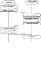
- FIG. 10 is a sequence for explaining an operation example in the communication system 100 having the configuration shown in FIG. 8 according to the first embodiment.
- the first communication device 111A executes communication in the normal operation mode (normal communication mode, first communication mode) based on the whitelist (step S101), and the second communication device 111B is not yet. It is assumed that the communication state is set (step S102).
- the controller 120 of the first communication device 111A monitors the operating state such as the amount of communication data, the communication speed, the communication time, and the error detection frequency, and determines the presence or absence of a failure or communication failure in the first communication device. Detect (step S103). Further, the controller 120 may detect the presence or absence of a defect in the communication device 111A by executing the self-diagnosis at the set timing. Further, each communication device 111 may be provided with a detector that detects a defect, and the controller 120 may acquire the detection result of the detector.
- step S103 If the controller 120 of the first communication device 111A does not detect a malfunction (step S103, NO), the controller 120 continues to execute communication in the normal communication mode. Further, when the controller 120 of the first communication device 111A detects a defect during execution of communication in the normal communication mode (step S103, YES), the controller 120 transmits information indicating the defect to the communication control management device 5.
- Step S105 Information indicating a defect transmitted by the first communication device 111A of the communication control apparatus 101 is acquired by the communication control management apparatus 5 (step S105).
- the control unit 61 of the communication control management device 5 sets the second communication device 111B of the communication control device 101 to the normal communication mode according to the information indicating the failure from the first communication device 111A of the communication control device 101,
- the communication device 111A is controlled so as not to communicate.
- the control unit 61 of the communication control management device 5 refers to the second communication device 111B of the communication control device 101 which is the source of the information indicating the defect.
- An instruction to switch to the normal communication mode is given (step S106).
- the instruction to switch from the communication control management device 5 to the normal communication mode is acquired by the second communication device 111B of the communication control device 101, which is the source of the information indicating the defect (step S107).
- the controller 120 of the second communication device 111B switches the operation mode to the normal communication mode in response to the switching instruction from the communication control management device 5 to the normal communication mode (step S108).
- the control unit 61 of the communication control management device 5 refers to the first communication device 111A of the communication control device 101 which is the source of the information indicating the defect. It is instructed to enter the non-communication state (step S109).
- the instruction to switch to the non-communication state from the communication control management device 5 is acquired by the first communication device 111B, which is the source of the information indicating the failure (step S110).
- the controller 120 of the first communication device 111A switches the operation mode to the non-communication state in response to the switching instruction from the communication control management device 5 to the non-communication state (step S111).
- the operation mode of the first communication device and the second communication device can be switched so that the communication as the communication control device 101 is not interrupted.
- the communication control management device (device management server) 5 sets the first communication device 111A in a non-communication state after the switching to the normal communication mode of the second communication device 111B is completed. Thereby, the communication control management device 5 can reliably ensure the availability of communication in the communication control device 101.
- the communication control apparatus 101 performs communication control in which, when a failure occurs in one communication device that is performing communication in the normal communication mode, the other communication device switches to perform communication in the normal communication mode. It may be realized in the device 101. For example, when the first communication device that is executing communication in the normal communication mode detects a defect, the controller 120 of the first communication device 111A requests the second communication device 111B to switch to the normal communication mode. May be. As a result, the second communication device 111B can be started in the normal communication mode in response to the request, and the first communication device 111A can be made to transition to the non-communication state. In this case, the first communication device and the second communication device can communicate with each other by their addresses.
- FIG. 11 is a diagram showing a second configuration example of the communication system 100 ′ according to the first embodiment.
- the communication system 100'shown in FIG. 11 replaces the communication control device 30 with the communication control device 101'in the system configuration shown in FIG.
- the communication control apparatus 101′ has a plurality of communication devices 111C and 111D arranged in series between the network NW and the client apparatus 10.
- each device other than the communication control device 101′ in the communication system 100′ can be realized by the same configuration as the device shown in FIG. Therefore, detailed description of the configuration of each device other than the communication control device 101'will be omitted below.
- the communication control device 31 is also configured to include a plurality of communication devices arranged in series between the network NW and the server device 20 as in the communication control device 101'. good.
- FIG. 12 is a block diagram showing a configuration example of the communication control device 101′ in the second configuration example of the communication system 100′ according to the first embodiment. In the configuration example illustrated in FIG.
- the communication control apparatus 101′ includes, as the plurality of communication devices 111, a first communication device 111C and a second communication device 111D that are arranged in series.
- the first communication device 111C connected to the network NW and the second communication device 111D connected to the client device 10 are connected in series.
- the communication control device 101' has a power supply 116 and a memory I / F 117 shared by the first communication device 111C and the second communication device 111D.
- the power supply 116 is connected to an external power supply and supplies the power from the external power supply to the communication devices 111C and 111D, as in FIG.
- the memory I / F 117 is an interface for setting a memory device 118 such as a memory card, as in FIG.
- the communication control device 101' may be realized as a system in which a plurality of communication devices having the same configuration as the communication control device 30 are arranged in series. In such a system, the plurality of communication devices 111'may each have a configuration such as a power supply and a memory I / F.
- Each of the first communication device 111C and the second communication device 111D has a configuration that executes the same communication process as the communication control device 30 shown in FIG. 1 described above. That is, in each communication control device 101, one of the first communication device 111C and the second communication device 111D arranged in series between the network NW and the client device 10 is in the normal communication mode (first communication). The mode) communicates, and the other communicates in the pass-through mode (second communication mode).
- the pass-through mode (second communication mode) is a communication mode in which input information is passed as it is and output.
- the normal communication mode is an operation mode in which communication is performed with encryption and decryption of transmitted / received data using a common key based on mutual authentication with the communication control device 31 on the server side as described above.
- the communication control device 101' is assumed to execute the communication in the whitelist operation mode which allows the communication with the destination in the whitelist as described above in the normal operation mode.
- the first communication device 111C and the second communication device 111D provided in series in the communication control device 101′ may be realized by two independent software for communication processing.
- one communication device may be operated as two communication devices that are arranged in parallel and realized by two pieces of software.
- Each communication device 111' has a function of detecting its own failure, unauthorized access, malware infection, or the like.
- the communication device 111' notifies the communication control management device (device management server) 5 of information indicating a failure such as a failure, an unauthorized access, or a malware infection, or a communication failure.
- each communication device 111's switches an operation mode according to an instruction from the communication control management device 5. For example, each communication device 111'switches from the pass-through mode to the normal communication mode or switches from the normal communication mode to the pass-through mode in response to an instruction from the communication control management device 5.
- each communication device 111′ (111C, 111D) has a controller 120, a bridge 132, a hub 133, a bridge 134, a reader/writer 135, an IC card 140, and the like, as in the configuration shown in FIG. I shall. Further, it is assumed that the controller 120 has an MPU 121, a RAM 122, a SAM 123, a data memory 124, and the like. Since each of these configurations can be realized with the same configuration as each configuration shown in FIG. 9, detailed description will be omitted.
- FIG. 13 is a sequence for explaining an operation example in the communication system 100'with the configuration shown in FIG. 11 according to the first embodiment.
- the first communication device 111C executes communication in the normal operation mode (normal communication mode) based on the whitelist (step S121), and the second communication device 111D operates in the pass-through mode. (Step S122).
- the controller 120 of the first communication device 111C monitors the operation state such as the communication data amount, the communication speed, the communication time, the error detection frequency, and the like to determine whether there is a failure or a communication failure in the first communication device. It is detected (step S123). Further, the controller 120 may detect the presence or absence of a defect in the communication device 111A by executing the self-diagnosis at the set timing. Further, each communication device 111 may be provided with a detector that detects a defect, and the controller 120 may acquire the detection result of the detector.
- step S123 If the controller 120 of the first communication device 111C does not detect any malfunction (NO in step S123), the controller 120 continues to execute communication in the normal communication mode. Further, when the controller 120 of the first communication device 111C detects a defect during communication in the normal communication mode (YES in step S123), the controller 120 notifies the communication control management device 5 of information indicating the defect (step S124).
- Information indicating a defect notified by the first communication device 111C of the communication control apparatus 101' is acquired by the communication control management apparatus 5 (step S125).
- the control unit 61 of the communication control management device 5 sets the second communication device 111D of the communication control device 101'in the normal communication mode according to the information indicating the defect from the first communication device 111C of the communication control device 101'.
- the first communication device 111C is controlled to be in the pass-through mode.
- the control unit 61 of the communication control management device 5 refers to the second communication device 111D of the communication control device 101'which is the source of the information indicating the defect.
- the instruction to switch to the normal communication mode from the communication control management device 5 is acquired by the second communication device 111D in the communication control device 101′ that is the source of the information indicating the malfunction (step S127).
- the controller 120 of the second communication device 111D switches the operation mode to the normal communication mode in response to the switching instruction from the communication control management device 5 to the normal communication mode (step S128).
- the control unit 61 of the communication control management device 5 sends the information indicating the defect to the first communication device 111C of the communication control device 101'.
- the instruction to switch to the pass-through mode from the communication control management device 5 is acquired by the first communication device 111C, which is the source of the information indicating the failure (step S130).
- the controller 120 of the first communication device 111C switches the operation mode to the pass-through mode in response to the switching instruction from the communication control management device 5 to the pass-through mode (step S131).
- the communication control device has a redundant configuration in which a plurality of communication devices are provided.
- the communication control device even if a failure or a communication failure occurs in the communication control device for ensuring the security in data communication via the network, the communication can be continued without interruption. It is possible to realize communication operation with reliable availability.
- FIG. 14 is a diagram illustrating a configuration example of the communication system 200 according to the second embodiment.
- the communication control device 30 on the client side is replaced with the communication control device 201 in the system configuration shown in FIG.
- the communication control apparatus 201 includes a plurality of communication devices 211A, 211B, and 211C arranged in parallel between the network NW and the client apparatus 10 via the distributed controllers 212A and 212B. Have.
- each device other than the communication control device 201 in the communication system 200 can be realized by the same configuration as the device shown in FIG. Therefore, detailed description of configurations other than the communication control device 200 will be omitted.
- the communication control device 31 on the server side like the communication control device 201, also has a plurality of communications arranged in parallel between the network NW and the server device 20 via a distributed controller. It may be configured to include a device.
- FIG. 15 is a block diagram showing a configuration example of the communication control device 201 in the configuration example of the communication system 200 according to the second embodiment.
- the communication control device 201 has three communication devices 211A, 211B, 211C arranged in parallel as a plurality of communication devices 211.
- the plurality of communication devices 211A to 211C are connected in parallel between the distributed controller 212A connected to the network NW and the distributed controller 212B connected to the client device 10.
- Each of the plurality of communication devices 211A to 211C has a configuration that executes the same communication processing as the communication control device 30 shown in FIG. 1 described above.
- the distributed controllers 212A and 212B control to distribute the load of communication processing to the plurality of communication devices 211A to 211C. Therefore, the controllers included in the respective communication devices 211A to 211C can also perform the encryption / decryption process and the mutual authentication process using the certificate.
- the communication control device 201 has a power supply 216 shared by a plurality of communication devices 211A to 211C and the distributed controllers 212A and 212B.
- the communication control device 201 also has a memory I / F 217 shared by a plurality of communication devices 211A to 211C.
- the power supply 216 is connected to an external power supply and supplies the power from the external power supply to each of the communication devices 211A to 211C and the distributed controllers 212A and 212B.
- the memory I / F 217 is an interface for setting a memory device 218 such as a memory card. For example, a memory device 218 that stores setting information for each communication device 211 is set in the memory I / F 217.
- the number of communication devices 211 arranged in parallel is not limited to three, and may be a plurality. Further, in the communication control device 201, the communication devices 211 arranged in parallel may be those that perform the same communication processing, and may have different processing capacities. Further, in the communication control device 201, the communication devices 211 arranged in parallel may be replaced with those having different processing capacities.
- the communication control device 201 is realized as a distributed device system in which a plurality of communication devices having the same configuration as the communication control device 30 are arranged in parallel between the two distributed controllers 212A and 212B. May be.
- each communication device constituting the distributed device system may be configured as a device that has a power supply, a memory I / F, and the like and can operate independently.
- each communication device 211 (211A to 211C) has a controller 220, a bridge 232, a hub 233, a bridge 234, a reader/writer 235, and an IC card 240.
- the controller 220 controls the communication device 211.
- the controller 220 has an MPU 221, a RAM 222, a SAM 223, a data memory 224, and the like.
- the MPU 221 is an example of a processor that controls the controller 220.
- the MPU 221 realizes various processes by executing a program stored in a data memory 224 or the like.
- the controller 220 executes a program such as communication control, failure detection, communication failure detection, communication status monitoring, self-diagnosis, and log information collection by the MPU 221 executing a program.
- the controller 220 causes the MPU 221 to execute a program, thereby performing mutual authentication processing with the server-side communication control device 31, encryption processing of data transmitted from the client device 10 to the network NW, and client processing via the network NW. You may make it perform the decoding process etc. of the encrypted data transmitted to an apparatus.
- the controller 220 may request the IC card 240 to perform at least one of mutual authentication processing, encryption processing, and decryption processing.
- the RAM 222 is a random access memory.
- the RAM 222 functions as a working memory that holds work data.
- the SAM 223 is a serial access memory.
- the data memory 224 is a rewritable nonvolatile memory.
- the data memory 224 stores programs and setting information.
- the data memory 224 stores a white list showing a list of destinations that are allowed to communicate.
- the controller 220 refers to the white list stored in the data memory 224 and executes communication in the normal communication mode (first communication mode).
- the data memory 224 may store log information indicating the operating state of the communication device.
- the data memory 224 may store information indicating the amount of communication in the communication device.
- the data memory 224 executes self-diagnosis processing such as analysis of log data.
- the bridges 232 and 234 function as communication interfaces (communication units). Bridges 232 and 234 are connected to controller 220 via hub 233. The bridge 232 executes communication on the network NW side in the communication device 211. The bridge 232 realizes communication as the NW communication unit 32 shown in FIG. The bridge 232 supplies the data received from the network NW to the controller 220 via the hub 233. Further, the bridge 234 sends the data encrypted by the controller 220 or the IC card 240 to the network NW.
- the bridge 234 executes communication on the client device 10 side in the communication device 211.
- the bridge 234 realizes communication as the device communication unit 34 shown in FIG.
- the bridge 234 supplies data from the client device 10 to the controller 220 via the hub 233. Further, the bridge 234 sends the data obtained by decrypting the encrypted data from the network NW by the controller 220 or the IC card 240 to the client device 10.
- the reader/writer 235 and the IC card 240 correspond to the reader/writer 35 and the IC card 40 shown in FIG. 3 described above.
- the IC card 240 can be realized by having the same configuration as the IC card 40 shown in FIG. 4 described above. Further, the IC card 240 has a processing function similar to that of the IC card 40 shown in FIG. 5 described above, and functions as an example of an authentication unit in the communication control device 201.
- each distributed controller 212 (212A, 212B) has a controller 251, a memory 252, a hub 253, and an interface (I/F) 254.
- the controller 251 controls the distributed controller 212.
- the controller 251 has a processor and various memories. In the controller 251, various processes are realized by the processor executing the program. For example, the controller 251 performs distributed control of the communication load on the communication devices 211A to 211C by executing the program by the processor.
- the memory 252 stores setting information and the like.
- the memory 252 stores a threshold value for determining the distribution of the communication load.
- the controller 251 determines a communication device to execute communication processing from a plurality of communication devices according to the communication load based on setting information such as a threshold value stored in the memory 252.
- the hub 253 is an interface for connecting the network NW or the client device 10 and the plurality of communication devices 211A to 211C.
- the hub 253 is controlled by the controller 251 as a communication device to be connected.
- the interface 254 is an interface for acquiring setting information and the like.
- the interface 254 is configured as a communication unit for communicating with the communication control management device 5.
- the interface 254 may be configured by a memory reader that reads information from a memory device such as a memory card that stores setting information such as a threshold value.
- the interface 254 may be an interface for connecting an external device that supplies setting information such as a threshold value.
- FIG. 16 is a flowchart for explaining an operation example of the distributed controller 212 (212A, 212B) in the communication system 200 having the configuration shown in FIGS. 14 and 15.
- the distribution controller 212 receives setting information input by the interface 254 or the like for distributed processing by the plurality of communication devices 211A to 211C (S201).
- the controller 251 of the distribution controller 212 (212A or 212B) performs the distributed processing by the plurality of communication devices 211A to 211C based on the input setting information.
- a threshold value for determining is set (step S202).
- the first threshold is a determination reference value for the processing load of the entire communication control apparatus 201 for determining whether or not to perform communication processing with one communication device.
- the controller 251 of the distributed controller 212 executes communication processing with one communication device if the processing load of the communication control apparatus 201 as a whole is less than the first threshold value, and with a plurality of communication devices if the load is equal to or more than the first threshold value. Communication processing shall be executed in a distributed manner.
- the second threshold value is a determination reference value for the processing load of the entire communication control device 201 for determining whether or not the communication processing is executed by the three communication devices.
- the controller 252 of the distributed controller 212 distributes the communication processing among the three communication devices and executes the communication processing if the processing load of the entire communication control apparatus 201 is equal to or more than the second threshold, and is equal to or more than the first threshold and less than the second threshold. In that case, the communication process is divided into two communication devices to execute the communication process.
- the threshold as the setting information for carrying out the distributed processing may be set appropriately.
- the controllers 251 of the distributed controllers 212A and 212B monitor the processing load on the communication device based on the communication amount and the like (step S203). For example, since the communication device 211 executes the decoding process for the information input from the network NW side, the controller 251 of the distributed controller 212A monitors the amount of data input from the network NW side as a processing load. Further, since the communication device 211 executes the encryption process for the information input from the client device 10, the controller 251 of the distributed controller 212B monitors the amount of data input from the client device 10 as a processing load.
- the controller 251 of the distributed controller 212 causes one communication device 211 to execute the communication process (step S205). For example, when a plurality of communication devices are operating, the controller 251 executes communication with only one communication device when the load of the processing being monitored is less than the first threshold, and the communication is performed. The communication device that is not executed is transited to the non-communication state (sleep state). As a result, when the processing load is less than the first threshold value, the distributed controller 212 executes the communication process with only one communication device and puts the other communication devices in the non-communication state, which wastes power consumption. Can be suppressed.
- the controller 251 of the distributed controller 212 determines whether the processing load is less than the second threshold if the processing load being monitored is equal to or more than the first threshold (step S204, NO) (step S206). ). When the processing load is equal to or greater than the first threshold value and less than the second threshold value (step S206, YES), the controller 251 distributes the processing load to the two communication devices to execute the communication processing (step S207).
- the controller 251 will use the second communication device when the load of the processing being monitored is equal to or greater than the first threshold value and less than the second threshold value.
- 211B is brought into a communicable state.
- the controller 251 distributes the information output from the hub 253 to the communication device 211A and the communication device 211B.
- the distributed controller 212 can execute distributed processing by two communication devices when the processing load is greater than or equal to the first threshold and less than the second threshold. As a result, the distributed controller 212 can distribute the communication processing among a plurality of communication devices that operate according to the load, and can prevent a data delay or the like from occurring due to insufficient processing capacity.
- the controller 251 of the distributed controller 212 causes the three communication devices to execute the communication processing by being distributed to the three communication devices if the load of the processing being monitored is equal to or higher than the second threshold value (step S206, NO) (step S208). ..
- the controller 251 can communicate with the third communication device 211A when the load of the monitored process exceeds the second threshold value. It will be in a state.
- the controller 251 distributes the information output from the hub 253 to the communication device 211A, the communication device 211B, and the communication device 211C.
- the distributed controller 212 can perform processing in a distributed manner among three communication devices (maximum number of communication devices) when the processing load is equal to or greater than the second threshold value.
- the distributed controller 212 can perform communication processing in a distributed manner among a plurality of communication devices whose processing is operated according to the load, and can prevent data delay and the like from occurring due to insufficient processing capacity.
- the above-mentioned operation example has been described on the assumption that a plurality of communication devices operate normally, but the distributed controller detects a failure such as a failure or a communication failure in each communication device and causes a failure.
- the above-described distributed control may be performed by a device other than the communication device in which the error occurs. Further, when a problem occurs in all the communication devices, the distributed controller may operate any one communication device in the pass-through mode to ensure the continuation of data communication.
- the communication control device described above has a plurality of equivalent communication devices arranged in parallel, but a plurality of communication devices having different processing capabilities may be arranged in parallel. Further, one communication device may be used as the main processing device, and the other communication device may be used as the slave processing device to assist the processing of the main communication device. Furthermore, the processing content performed by the communication device may be performed separately.
- the communication system has a communication control device in which a plurality of communication devices are arranged in parallel between the network and the client device via a distributed controller.
- the distributed controller monitors the processing load on the communication control device and distributes and executes the communication processing by the number of communication devices according to the processing load.
- FIG. 17 is a diagram showing a configuration example of the communication system 300 and the communication control device 301 according to the third embodiment.
- a communication system 300 shown in FIG. 17 is obtained by replacing the client side communication control device 30 with a communication control device 301 in the system configuration shown in FIG.
- the server-side communication control device 31 arranged between the network NW and the server device 20 may have the same configuration as the communication control device 301.
- each device other than the communication control device 301 in the communication system 300 can be realized by the same configuration as the device shown in FIG. 1, and thus detailed description thereof will be omitted.
- the communication control device 301 includes a power supply 316, a memory I / F 317, a controller 320, a bridge 332, a hub 333, a bridge 334, a reader / writer 335, an IC card 340, and the like.
- the controller 320 controls the communication device 211.
- the controller 320 has an MPU 321 and a RAM 322, a SAM 323, a data memory 324, and the like.
- the MPU 321 is an example of a processor that controls the controller 320.
- the MPU 321 realizes various processes by executing a program stored in a data memory 324 or the like.
- the controller 320 executes processes such as communication control, failure detection, communication failure detection, communication volume analysis, self-diagnosis, log information storage, and log information transmission when the MPU 321 executes a program.
- the controller 320 causes the MPU 321 to execute the program, thereby performing mutual authentication processing with the server-side communication control device 31, encryption processing of data transmitted from the client device 10 to the network NW, and client processing via the network NW. Decryption processing of the encrypted data transmitted to the device 10 may be performed. Further, the controller 320 may request the IC card 340 to perform at least one of mutual authentication processing, encryption processing, and decryption processing.
- the RAM 322 is a random access memory.
- the RAM 322 functions as a working memory that holds work data.
- the SAM 323 is a serial access memory.
- the data memory 324 is a rewritable nonvolatile memory.
- the data memory 324 stores programs and setting information. For example, the data memory 324 stores a white list showing a list of destinations that are allowed to communicate.
- the controller 320 executes communication in the normal communication mode (first communication mode) with reference to the white list stored in the data memory 324. Further, the data memory 324 may store log information indicating the operating state of the communication control device. Further, the data memory 324 stores the analysis information of the communication amount in the communication control device by the controller 320.
- the bridges 332 and 334 function as a communication interface (communication unit).
- the bridges 332 and 334 are connected to the controller 320 via the hub 333.
- the bridge 332 executes communication on the network NW side in the communication control device 301.
- the bridge 332 realizes communication as the NW communication unit 32 shown in FIG.
- the bridge 332 supplies the data received from the network NW to the controller 320 via the hub 333. Further, the bridge 334 sends the data encrypted by the controller 320 or the IC card 340 to the network NW.
- the bridge 334 executes communication on the client device 10 side in the communication control device 301.
- the bridge 334 realizes communication as the device communication unit 34 shown in FIG.
- the bridge 334 supplies the data from the client device 10 to the controller 320 via the hub 333. Further, the bridge 334 sends the data obtained by decrypting the encrypted data from the network NW with the controller 320 or the IC card 340 to the client device 10.
- the reader/writer 335 and the IC card 340 correspond to the reader/writer 35 and the IC card 40 shown in FIG. 3 described above.
- the IC card 340 can be realized by having the same configuration as the IC card 40 shown in FIG. 4 described above. Further, the IC card 340 has the same processing function as the IC card 40 shown in FIG. 5 described above, and functions as an example of the authentication unit in the communication control device 301.
- the power source 316 is connected to an external power source and supplies the power from the external power source to each unit in the communication control device 301.
- the memory I / F 317 is an interface for setting a memory device 318 such as a memory card.
- a memory device 318 that stores setting information for the communication control device 301 is set in the memory I / F 317.
- FIG. 18 is a sequence for explaining a first operation example in the communication system 300 shown in FIG.
- the communication control device 301 accumulates log information including the amount of communication in normal operation.
- the controller 320 of the communication control device 301 stores information indicating the communication amount of the communication control device 301 in the data memory 324 by monitoring the data passing through the bridges 332 and 334 as the communication interface.
- the controller 320 of the communication control device 301 analyzes the information indicating the communication amount stored as log information in the data memory 324, and stores the analysis information of the communication amount as the analysis result in the data memory 324 (step S301). For example, the controller 320 analyzes the communication amount in a predetermined cycle and records the analysis information of the communication amount in the data memory 324.
- the communication volume analysis information may, for example, indicate the communication volume per hour, or may indicate the communication volume and the tendency of increase / decrease in the communication volume for each time zone, and the communication volume may be Information indicating a time zone in which the communication volume is less than a predetermined threshold or a time zone in which the communication volume is minimized may be used.
- the communication amount analysis information may be information for determining the time at which the communication control device 301 executes the self-diagnosis.
- the controller 320 of the communication control device 301 transmits the analysis information of the communication amount stored in the data memory 324 to the communication control management device (device management server) 5 (step S302).
- the controller 320 may transmit the analysis information of the communication amount at a predetermined timing, or may transmit the analysis information in response to the request from the communication control management device 5.
- the controller 320 self-determines the time zone in which the communication amount is low in the communication control management device 5, and transmits the analysis information of the communication amount to the communication control management device 5 in the time zone when it is determined that the communication amount is low. May be.
- the analysis information of the communication amount transmitted from the communication control device 301 is acquired by the communication control management device 5 (step S303).
- the control unit 61 of the communication control management device 5 stores the analysis information of the communication amount received by the NW communication unit 60 in the storage unit 66 in association with the identification information indicating the communication control device 301 of the transmission source.
- the control unit 61 determines a time or a time zone in which the communication control device 301 should execute the self-diagnosis based on the received analysis information of the communication amount (step S304).
- control unit 301 identifies, as the execution time (scheduled execution time) of the self-diagnosis, the time at which the time required for the self-diagnosis processing can be secured in the time zone in which the communication volume is less than the predetermined threshold based on the analysis information of the communication volume. To do.
- execution time scheduled execution time
- the time required for self-diagnosis processing can be secured regardless of whether it is below the predetermined threshold value (scheduled implementation time). Time).
- the control unit 61 After determining the execution time of the self-diagnosis, the control unit 61 transmits a life / death confirmation query to the communication control device 301 at the execution time of the self-diagnosis (step S305).
- the life-and-death confirmation query requests a response regarding whether or not it is operating normally.
- the controller 320 of the communication control device 301 Upon receiving the life-or-death confirmation query from the communication control management device 5 (step S306), the controller 320 of the communication control device 301 transmits a response indicating normality during normal operation (step S307). Further, the communication control device 301 may respond to the life / death confirmation query with the date and time when the previous self-diagnosis was performed.
- the control unit 61 of the communication control management device 5 determines whether or not to perform the self-diagnosis based on the response from the communication control device 301 (step S308). For example, the control unit 61 causes the communication control device 301 to perform the self-diagnosis when there is no response from the communication control device or when a predetermined period or more has passed from the date and time when the previous self-diagnosis was performed. to decide. Further, the control unit 61 may perform the self-diagnosis regardless of the content of the response from the communication control device 301. When performing the self-diagnosis, the control unit 61 of the communication control management device 5 requests the communication control device 301 to perform the self-diagnosis (step S309).
- the controller 320 of the communication control management device 5 receives the request for performing the self-diagnosis from the communication control management device 5, it determines whether or not it is currently in a situation where it can perform the self-diagnosis (step S311). For example, the controller 320 shall perform self-diagnosis if the current traffic is less than a predetermined threshold.
- the self-diagnosis execution time designated by the communication control management device 5 is based on the past communication amount (communication amount analysis information), and there is a possibility that the communication amount is actually large at the set time. Because there is.
- the system according to the third embodiment controls the communication control device and the entire communication system as much as possible to execute self-diagnosis without applying a load. Therefore, the controller of the communication control device determines that the self-diagnosis is not performed (delayed) when the actual communication amount is large.
- step S311 When performing the self-diagnosis (step S311, YES), the controller 320 performs the self-diagnosis (step S312) and transmits information indicating the execution result of the self-diagnosis to the communication control management device 5. In this case, the information indicating the execution result of the self-diagnosis is transmitted from the communication control device 301 and is acquired by the communication control management device 5 (step S313).
- step S311, NO the controller 320 transmits a notification indicating that the self-diagnosis is not performed to the communication control management device 5 (step S314). In this case, the notification indicating that the self-diagnosis is not performed is acquired by the communication control management device 5 as a response to the self-diagnosis execution request (step S315).
- the control unit 61 of the communication control management device 5 saves the self-diagnosis result in the storage unit 66 (step 316). For example, when the self-diagnosis is performed by the communication control device 30, the control unit 61 stores the information indicating the execution result of the self-diagnosis in the storage unit 66 in association with the identification information of the communication control device 301 together with the execution date and time. .. Further, when the self-diagnosis is not performed by the communication control device 30, the control unit 61 stores the information indicating that the self-diagnosis could not be performed in the storage unit 66 in association with the identification information of the communication control device 301. ..
- control unit 61 of the communication control management device 5 verifies the presence or absence of an abnormality in the acquired self-diagnosis execution result.
- the control unit 61 notifies an alert indicating that the communication control device 301 or the communication system 300 has an abnormality (step S318).
- the control unit 61 may notify that there is an abnormality in the communication control device 301 or the communication system 300.
- the communication control management device acquires the analysis information of the communication amount in the communication control device, and the communication control management device controls the communication based on the analysis information of the communication amount.
- the communication control management device can cause the communication control device to perform the self-diagnosis at a time when the communication amount is small and the normal communication process is not affected even when the self-diagnosis is performed.
- the self-diagnosis for confirming the state of the communication control device and early detection of a failure or communication failure can be efficiently performed without imposing a load on the original communication system.
- FIG. 19 is a sequence for explaining a second operation example in the communication system 300 shown in FIG.
- the controller 320 of the communication control device 301 analyzes the information indicating the communication amount to be stored as log information in the data memory 324, and analyzes the analysis information of the communication amount as the analysis result, as in the first operation example described above. It is stored in 324 (step S321).
- the controller 320 of the communication control device 301 determines the scheduled execution time for executing the self-diagnosis based on the analysis information of the communication amount stored in the data memory 324 at a predetermined timing (step S322). For example, the controller 320 identifies, as the self-diagnosis execution time (scheduled execution time), the time at which the time required for the self-diagnosis processing can be secured in the time zone in which the communication traffic is less than the predetermined threshold based on the communication traffic analysis information. ..
- the controller 320 When the scheduled execution time of the self-diagnosis is determined, the controller 320 notifies the communication control management device 5 of the scheduled execution time of the self-diagnosis (S323). In this case, the control unit 61 of the communication control management device 5 stores the information indicating the scheduled execution time of the self-diagnosis notified from the communication control device 301 in association with the identification information of the communication control device 301. May be. However, the controller 320 does not have to notify the communication control management device 5 of the scheduled time for performing the self-diagnosis.
- the control unit 61 determines whether or not the self-diagnosis execution self-diagnosis is possible (step S324). For example, the controller 320 performs a self-diagnosis if the current traffic is less than a predetermined threshold. When the self-diagnosis is performed (step S324, YES), the controller 320 performs the self-diagnosis (step S325) and transmits information indicating the execution result of the self-diagnosis to the communication control management device 5. Information indicating the execution result of the self-diagnosis is transmitted from the communication control device 301 and acquired by the communication control management device 5 (step S326).
- step S324 the controller 320 transmits a notification indicating that the self-diagnosis is not performed to the communication control management device 5 (step S327).
- the notification indicating that the self-diagnosis is not executed is acquired by the communication control management device 5 as a response to the self-diagnosis execution request (step S328).
- the control unit 61 of the communication control management device 5 stores the self-diagnosis result in the storage unit 66 (step 329). Further, when the self-diagnosis is not performed by the communication control device 30, the control unit 61 stores the information indicating that the self-diagnosis could not be performed in the storage unit 66 in association with the identification information of the communication control device 301. ..
- control unit 61 of the communication control management device 5 verifies whether or not there is an abnormality in the acquired execution result of the self-diagnosis (step S330).
- the control unit 61 notifies an alert indicating that the communication control device 301 or the communication system 300 has an abnormality (step S331). ..
- the communication control device itself sets the scheduled time for carrying out the self-diagnosis based on the analysis information of the communication amount.
- the communication control device can be planned to perform the self-diagnosis at a time when the amount of communication is small and the self-diagnosis does not affect the normal communication processing.
- the communication control management device can efficiently perform self-diagnosis for confirming the state of the communication control device and detecting a failure or communication failure at an early stage without imposing a load on the communication system. ..
- the communication system according to the fourth embodiment has the same configuration as the communication system 300 according to the third embodiment described above. Therefore, the fourth embodiment will be described as an example of application to the communication system 300 shown in FIG. 17 described in the third embodiment.
- FIG. 20 is a sequence for explaining a first operation example in the communication system 300 according to the fourth embodiment.
- the communication control device 301 stores log information indicating an operating state in the data memory 324.
- the log information stored in the data memory 324 is information indicating the operation history of the communication control device 301.
- information that should be urgently notified to the communication control management device 5 such as unauthorized access may be stored as log information, but is immediately notified to the communication control management device 5.
- the information indicating the amount of communication in normal operation may be stored in the data memory 324 as log information.
- the controller 320 of the communication control device 301 stores information indicating the communication amount of the communication control device 301 in the data memory 324 by monitoring the data passing through the bridges 332 and 334 as the communication interface.
- the controller 320 of the communication control device 301 analyzes the information indicating the communication amount stored as log information in the data memory 324, and stores the analysis information of the communication amount as the analysis result in the data memory 324 (step S401). For example, the controller 320 analyzes the communication amount at a predetermined cycle and records the analysis information of the communication amount in the data memory 324.
- the communication volume analysis information may, for example, indicate the communication volume per hour, or may indicate the communication volume and the tendency of increase / decrease in the communication volume for each time zone, and the communication volume may be Information indicating a time zone in which the communication volume is less than a predetermined threshold or a time zone in which the communication volume is minimized may be used.
- the communication amount analysis information may be any information for determining the time when the communication control device 301 transmits the log information to the communication control management device (device management server) 5.
- the controller 320 of the communication control device 301 transmits the analysis information of the communication amount stored in the data memory 324 to the communication control management device (device management server) 5 (step S402).
- the controller 320 may transmit the analysis information of the communication amount at a predetermined timing, or may transmit the analysis information in response to the request from the communication control management device 5.
- the controller 320 self-determines the time zone in which the communication amount is low in the communication control management device 5, and transmits the analysis information of the communication amount to the communication control management device 5 in the time zone when it is determined that the communication amount is low. May be.
- the communication amount analysis information transmitted from the communication control device 301 is acquired by the communication control management device 5 (step S403).
- the control unit 61 of the communication control management device 5 stores the communication amount analysis information received by the NW communication unit 60 in the storage unit 66 in association with the identification information indicating the communication control device 301 that is the transmission source (step S404).
- the control unit 61 determines a schedule (log collection schedule) at which each communication control device 301 transmits log information, based on the analysis information of the communication amount from each communication control device 301 stored in the storage unit 66 ( Step S405).
- control unit 301 causes each communication control device 301 to output log information based on the analysis information of the communication amount from each communication control device in the communication system so that the communication amount in the entire network NW becomes less than a predetermined threshold. Schedule the time (time zone) when transmission is possible.
- the control unit 61 notifies each communication control device 301 of the time (sending time) at which the log information is sent (step S406).
- the controller 320 of the communication control device 301 receives the notification of the transmission time of the log information from the communication control management device 5 (step S407), the controller 320 stores the transmission time of the log information in the data memory 324 (step S408).
- the controller 320 transmits the log information stored in the data memory 324 to the communication control management device 5 (step S409).
- the log information transmitted from the communication control device 301 is transmitted to the communication control management device 5 via the network NW and received by the communication control management device 5 (step S410).
- the control unit 61 of the communication control management device 5 saves the log information received from the communication control device 301 in the storage unit 66 (step 411). For example, the control unit 61 stores the received log information together with the implementation date and time in the storage unit 66 in association with the identification information of the communication control device 301.
- the communication control device connected to the client device transmits the analysis information of the communication amount of the communication control management device to the communication control management device, and the communication control management device in the communication system.
- the time when each communication control device transmits the log information is scheduled based on the analysis information of the communication amount from each communication control device.
- each communication control device 301 determines the time when the log information is transmitted based on the analysis information of the communication amount, and the communication control management device takes into account the communication amount in each communication control device of the entire communication system.
- Each communication control device can decide to send the log information. As a result, it is possible to control the time at which each communication control device sends log information in consideration of not only the individual communication control device but also the load expected to occur in the entire network.
- FIG. 21 is a sequence for explaining a second operation example in the communication system 300 according to the fourth embodiment.
- the controller 320 of the communication control device 301 analyzes the information indicating the communication amount to be stored as log information in the data memory 324, and analyzes the analysis information of the communication amount as the analysis result, as in the first operation example described above.
- the data is stored in the data memory 324 (step S421).
- the controller 320 of the communication control device 301 selects a candidate for the transmission time at which the communication control device 301 transmits log information based on the analysis information of the communication amount stored in the data memory 324 (step S422).
- the candidate for the transmission time may be one, may be a plurality, or may be indicated by a time zone.
- the controller 320 selects a time at which the communication control device 301 can transmit log information as a candidate for a transmission time based on the analysis information of the communication volume in the communication control device. Further, the control unit 301 selects a time (transmission time) at which the communication control device 301 can transmit log information from a time zone in which the communication volume is less than a predetermined threshold value, based on the analysis information of the communication volume in the communication control device. May be.
- the controller 3210 transmits the selected log information transmission time candidate to the communication control management device 5 (step S424).
- the communication control management device 5 acquires the candidate of the transmission time of the log information selected by the communication control device 301.
- the control unit 61 of the communication control management device 5 stores the information indicating the transmission time candidate of the log information received by the NW communication unit 60 in the storage unit 66 in association with the identification information indicating the communication control device 301 of the transmission source. (Step S425). As a result, the storage unit 66 stores information indicating candidates for transmission time of log information from each communication control device 301 in the communication system.
- the control unit 61 of the communication control management device 5 schedules the time when each communication control device 31 of the entire system sends the logo information based on the candidate of the transmission time of the log information of each communication control device 301 stored in the storage unit 66. (Schedule of log collection) is created (step S426). For example, the control unit 301 schedules candidates for transmission time of log information from each communication control device so that the communication volume in the entire network NW is less than a predetermined threshold value.
- the control unit 61 When the schedule of the transmission time of the log information is created, the control unit 61 notifies each communication control device 301 of the transmission time of transmitting the log information (step S427).
- the controller 320 of the communication control device 301 receives the notification of the log information transmission time from the communication control management device 5 (step S428), the controller 320 stores the log information transmission time in the data memory 324 (step S429).
- the controller 320 transmits the log information accumulated in the data memory 324 to the communication control management device 5 at the transmission time of the log information instructed by the communication control management device 5 (step S430).
- the log information transmitted from the communication control device 301 is transmitted to the communication control management device 5 via the network NW and received by the communication control management device 5 (step S431).
- the control unit 61 of the communication control management device 5 saves the log information received from the communication control device 301 in the storage unit 66 (step 432). For example, the control unit 61 stores the received log information together with the implementation date and time in the storage unit 66 in association with the identification information of the communication control device 301.
- the communication control device 301 selects candidates for the transmission time of the log information based on the analysis information of the communication amount of itself.
- the communication control management device 5 schedules candidates for transmission time of log information acquired from each communication control device 301 in the communication system 300 so as to reduce the load on the network NW.
- each communication control device 301 can reduce the load on the entire network when transmitting log information to the communication control management device. Further, since each communication control device selects a candidate for the transmission time of the log information, the processing load on the communication control management device 5 can be reduced. As a result, for example, even in a communication system in which the number of communication control devices is large, the time at which each communication control device transmits log information can be efficiently controlled.
- FIG. 22 is a sequence for explaining a third operation example in the communication system 300 according to the fourth embodiment.
- the controller 320 of the communication control device 301 analyzes the information indicating the communication amount to be stored as log information in the data memory 324, and analyzes the analysis information of the communication amount as the analysis result, as in the first operation example described above.
- the data is stored in the data memory 324 (step S441).
- the controller 320 of the communication control device 301 determines the scheduled transmission time at which the communication control device 301 transmits the log information based on the analysis information of the communication amount stored in the data memory 324 (step S442). For example, the controller 320 selects, as the scheduled transmission time, the time when the communication control device 301 can transmit the log information in the time zone when the communication amount is the least, based on the analysis information of the communication amount in the communication control device.
- the controller 320 estimates the congestion degree of the network at the scheduled transmission time of the selected log information (step S443). For example, the controller 320 estimates the network congestion degree from the time from when the inquiry for confirming the network congestion degree is transmitted to the communication control management device 5 to when the response from the communication control management device 5 is received.
- the inquiry transmitted to the communication control management device 5 is data for estimating network congestion, it is set to a small size data that does not itself become a load on the network.
- step S444, NO the controller 320 stops transmission of log information.
- the controller 320 selects the scheduled transmission time for transmitting the logo information again from the analysis information of the communication amount.
- step S444 determines that the log information can be transmitted, and controls the communication of the log information stored in the data memory 324. It transmits to the management apparatus 5 (step S445).
- the log information transmitted from the communication control device 301 is transmitted to the communication control management device 5 via the network NW and received by the communication control management device 5 (step S446).
- the control unit 61 of the communication control management device 5 saves the log information received from the communication control device 301 in the storage unit 66 (step 457).
- the communication control device sets the scheduled transmission time of the log information based on the analysis information of its own communication amount.
- the communication control device estimates the network congestion degree at the scheduled transmission time set by the time, and if the network congestion degree is less than the threshold value, the communication control device shall transmit the log information to the communication control management device.
- each communication control device can transmit log information to the communication control management device after confirming the actual congestion degree of the network at the scheduled transmission time set by itself.
- the processing required for the communication control management device 5 does not become large, and a large number of communication control devices do not impose a load on the network. You can collect log information.
Abstract
According to an embodiment, a communication control device comprises a first communication system connected between a first device and a network communications net and a second communication system connected between the first device and the network communications net separately from the first communication system. The first and second communication systems include a controller. The controller transmits information encrypted from the information transmitted from the first device to a second device to a second communication control device, connected between the network communications net and the second device, using a secret key issued by a private certificate authority and a common key determined by a process of mutual certification with the second communication control device in which process a client certificate is used, and performs communication in a first communication mode in which information decoded from the information transmitted from the second device to the first device is transmitted to the first device. When one of the communication systems executes communication in the first communication mode and a fault is detected in the communication system that is executing communication in the first communication mode, the controller switches the communication systems so that the other communication system executes communication in the first communication mode.
Description
本発明の実施形態は、通信制御装置および通信システムに関する。
An embodiment of the present invention relates to a communication control device and a communication system.
通信システムは、取り扱うデータおよび機器の制御情報をマルウェア等の攻撃から防御される必要がある。例えば、社会インフラとして設置される監視カメラ等の機器は、通信するデータの安全性を確保することが必要である。しかしながら、監視カメラなどの社会インフラを構築する各機器は、一旦設置されると、頻繁に置換えることが難しいため、安全対策が不十分になってしまうという問題がある。
The communication system needs to protect the data it handles and the control information of the device from attacks such as malware. For example, devices such as surveillance cameras installed as social infrastructure need to ensure the safety of data to be communicated. However, once installed, it is difficult to replace each device that builds social infrastructure, such as a surveillance camera, frequently, so there is a problem that safety measures become insufficient.
本発明が解決しようとする課題は、社会インフラシステムなどに用いる通信の安全性を向上させることができる通信制御装置および通信システムを提供することである。
An object to be solved by the present invention is to provide a communication control device and a communication system capable of improving the security of communication used in a social infrastructure system or the like.
実施形態によれば、通信制御装置は、第1の装置とネットワーク通信網との間に接続される第1の通信系統と、第1の通信系統とは別に第1の装置とネットワーク通信網との間に接続される第2の通信系統とを備える。第1の通信系統および前記第2の通信系統は、コントローラを有する。コントローラは、プライベート認証局により発行された秘密鍵、及びクライアント証明書を用いた前記ネットワーク通信網と第2の装置との間に接続される第2の通信制御装置との相互認証処理により決定される共通鍵を用いて、第1の装置から第2の装置へ送信される情報を暗号化した情報を第2の通信制御装置に送信し、第2の装置から第1の装置へ送信された情報を復号した情報を第1の装置に送信する第1の通信モードで通信を行う。コントローラは、何れか一方の通信系統が第1の通信モードでの通信を実行し、第1の通信モードでの通信を実行中の通信系統において不具合が検知された場合に他方の通信系統が第1の通信モードで通信を実行するように切り替える。
According to the embodiment, the communication control device includes a first communication system connected between the first device and the network communication network, and a first device and a network communication network separately from the first communication system. And a second communication system connected between the two. The first communication system and the second communication system have a controller. The controller is determined by mutual authentication processing between the private key issued by the private authentication authority and the second communication control device connected between the network communication network and the second device using the client certificate. Information transmitted from the first device to the second device is encrypted by using the common key to transmit to the second communication control device, and the information is transmitted from the second device to the first device. Communication is performed in the first communication mode in which the decrypted information is transmitted to the first device. In the controller, when one of the communication systems executes communication in the first communication mode and a defect is detected in the communication system executing the communication in the first communication mode, the other communication system becomes the first. The communication mode is switched to the communication mode 1.
以下、各実施形態について、図面を参照して説明する。
まず、各実施形態に係る通信システムのペースとなる基本的な構成例および動作例について説明する。
図1は、各実施形態に係る通信システムのベースとなる構成を有する通信システム1の構成例を示す図である。
通信システム1は、クライアント装置10(10-1~10-N)と、サーバ装置20と、クライアント側の通信制御装置30(30-1~30-N)(「第1の通信制御装置」の一例)と、サーバ側の通信制御装置31(「第1の通信制御装置」の一例)と、通信制御管理装置5(「プライベート認証局」の一例)と、ネットワーク6と、ゲートウェイ7と、を備える。以下の説明においては、ネットワーク6と、ネットワーク6とクライアント装置10等とを接続するゲートウェイ7と、をまとめて「ネットワークNW」とも称する。 Hereinafter, each embodiment will be described with reference to the drawings.
First, a basic configuration example and an operation example that serve as the pace of the communication system according to each embodiment will be described.
FIG. 1 is a diagram showing a configuration example of a communication system 1 having a configuration that is a base of the communication system according to each embodiment.
The communication system 1 includes a client device 10 (10-1 to 10-N), aserver device 20, and a communication control device 30 (30-1 to 30-N) on the client side (“first communication control device”). An example), a server-side communication control device 31 (an example of a “first communication control device”), a communication control management device 5 (an example of a “private certificate authority”), a network 6, and a gateway 7. Be prepared. In the following description, the network 6 and the gateway 7 that connects the network 6 to the client device 10 and the like are collectively referred to as “network NW”.
まず、各実施形態に係る通信システムのペースとなる基本的な構成例および動作例について説明する。
図1は、各実施形態に係る通信システムのベースとなる構成を有する通信システム1の構成例を示す図である。
通信システム1は、クライアント装置10(10-1~10-N)と、サーバ装置20と、クライアント側の通信制御装置30(30-1~30-N)(「第1の通信制御装置」の一例)と、サーバ側の通信制御装置31(「第1の通信制御装置」の一例)と、通信制御管理装置5(「プライベート認証局」の一例)と、ネットワーク6と、ゲートウェイ7と、を備える。以下の説明においては、ネットワーク6と、ネットワーク6とクライアント装置10等とを接続するゲートウェイ7と、をまとめて「ネットワークNW」とも称する。 Hereinafter, each embodiment will be described with reference to the drawings.
First, a basic configuration example and an operation example that serve as the pace of the communication system according to each embodiment will be described.
FIG. 1 is a diagram showing a configuration example of a communication system 1 having a configuration that is a base of the communication system according to each embodiment.
The communication system 1 includes a client device 10 (10-1 to 10-N), a
クライアント装置10は、クライアント側の通信制御装置30を介してネットワークNWと接続する。サーバ装置20は、サーバ側の通信制御装置31を介してネットワークNWと接続する。なお、クライアント装置10、およびサーバ装置20の構成の詳細については後述する。
The client device 10 connects to the network NW via the communication control device 30 on the client side. The server device 20 connects to the network NW via the communication control device 31 on the server side. The details of the configurations of the client device 10 and the server device 20 will be described later.
クライアント側の通信制御装置30は、クライアント装置10とネットワークNWとの間に接続され、クライアント装置10とサーバ装置20との間の通信を仲介する。クライアント側の通信制御装置30は、クライアント装置10によりサーバ装置20に対して送信されるデータを取得し、取得したデータをサーバ装置20に対して出力する。ここで、クライアント側の通信制御装置30は、サーバ装置20に対してデータを送信する際に、クライアント装置10から取得したデータを暗号化し、暗号化したデータをサーバ装置20に対して送信する。
The communication control device 30 on the client side is connected between the client device 10 and the network NW, and mediates communication between the client device 10 and the server device 20. The communication control device 30 on the client side acquires data transmitted to the server device 20 by the client device 10, and outputs the acquired data to the server device 20. Here, when the communication control device 30 on the client side transmits data to the server device 20, the data acquired from the client device 10 is encrypted, and the encrypted data is transmitted to the server device 20.
また、クライアント側の通信制御装置30は、サーバ装置20によりクライアント装置10に対して送信されるデータを取得し、取得したデータをクライアント装置10に対して出力する。ここで、クライアント側の通信制御装置30が取得するデータは暗号化されたデータである。クライアント側の通信制御装置30は、クライアント装置10にデータを出力する際に、サーバ装置20からサーバ側の通信制御装置31を介して取得したデータを復号し、復号したデータをクライアント装置10に出力する。
Further, the communication control device 30 on the client side acquires data transmitted to the client device 10 by the server device 20, and outputs the acquired data to the client device 10. Here, the data acquired by the communication control device 30 on the client side is encrypted data. When the communication control device 30 on the client side outputs data to the client device 10, it decodes the data acquired from the server device 20 via the communication control device 31 on the server side, and outputs the decoded data to the client device 10. To do.
サーバ側の通信制御装置31は、サーバ装置20とネットワークNWとの間に接続され、クライアント装置10とサーバ装置20との間の通信を仲介する。サーバ側の通信制御装置31は、サーバ装置20によりクライアント装置10に対して送信されるデータを取得し、取得したデータをクライアント装置10に対して送信する。ここで、サーバ側の通信制御装置31は、クライアント装置10に対してデータを送信する際に、サーバ装置20から取得したデータを暗号化し、暗号化したデータをクライアント装置10に対して送信する。
The communication control device 31 on the server side is connected between the server device 20 and the network NW, and mediates communication between the client device 10 and the server device 20. The communication control device 31 on the server side acquires data transmitted to the client device 10 by the server device 20, and transmits the acquired data to the client device 10. Here, when the communication control device 31 on the server side transmits data to the client device 10, the data acquired from the server device 20 is encrypted, and the encrypted data is transmitted to the client device 10.
また、サーバ側の通信制御装置31は、クライアント装置10によりサーバ装置20に対して送信されるデータを取得し、取得したデータをサーバ装置20に対して出力する。ここで、サーバ側の通信制御装置31が取得するデータは暗号化されたデータである。サーバ側の通信制御装置31は、サーバ装置20にデータを出力する際に、クライアント装置10からクライアント側の通信制御装置30を介して取得したデータを復号し、復号したデータをサーバ装置20に出力する。
Further, the communication control device 31 on the server side acquires the data transmitted to the server device 20 by the client device 10, and outputs the acquired data to the server device 20. Here, the data acquired by the communication control device 31 on the server side is encrypted data. When the communication control device 31 on the server side outputs data to the server device 20, it decodes the data acquired from the client device 10 via the communication control device 30 on the client side, and outputs the decoded data to the server device 20. To do.
クライアント側の通信制御装置30およびサーバ側の通信制御装置31が行うデータの暗号化には、例えば、SSL(Secure Socket Layer)/TLS(Trans port Layer Security)のプロトコルによる暗号化が行われる。クライアント側の通信制御装置30およびサーバ側の通信制御装置31は、例えば、SSL/TLSプロトコルを、HTTPと組み合わせることで、HTTPに含まれるデータを暗号化し、安全性を向上させたHTTPS(HTTP Secure)に置き換える。
Data encryption performed by the communication control device 30 on the client side and the communication control device 31 on the server side is performed by, for example, the SSL (Secure Socket Layer)/TLS (Transport Layer Security) protocol. The communication control device 30 on the client side and the communication control device 31 on the server side, for example, by combining the SSL/TLS protocol with HTTP, encrypts the data included in the HTTP to improve security (HTTPS Secure). ).
なお、クライアント側の通信制御装置30およびサーバ側の通信制御装置31が行うデータの暗号化は、HTTPをHTTPSとすることに限定されない。クライアント側の通信制御装置30およびサーバ側の通信制御装置31は、SSL/TLSプロトコルを種々の通信プロトコルと組み合わせることにより、安全性を向上させたセキュアな通信プロトコルに置き換えてもよい。例えば、クライアント側の通信制御装置30およびサーバ側の通信制御装置31は、FTP(File Transfer Protocol)をFTPS(FTP Secure)に置き換えてもよい。
Note that the data encryption performed by the communication control device 30 on the client side and the communication control device 31 on the server side is not limited to HTTP being HTTPS. The client-side communication control device 30 and the server-side communication control device 31 may be replaced with a secure communication protocol with improved safety by combining the SSL/TLS protocol with various communication protocols. For example, the communication control device 30 on the client side and the communication control device 31 on the server side may replace FTP (File Transfer Protocol) with FTPS (FTP Secure).
通信システム1において、クライアント側の通信制御装置30、またはサーバ側の通信制御装置31により暗号化されたデータがネットワークNWに出力される。換言すると、通信システム1におけるネットワークNWを流れるデータは、暗号化されたデータであり。このため、ネットワークNWで送受信されるデータに対し、外部から悪意をもってアクセスされデータが盗聴されてしまうような危険を回避し、安全性を向上させる。なお、ここでいうデータの盗聴とは、「データを盗み見る行為」または「データを抜き取る行為」をいう。
In the communication system 1, data encrypted by the communication control device 30 on the client side or the communication control device 31 on the server side is output to the network NW. In other words, the data flowing through the network NW in the communication system 1 is encrypted data. Therefore, the risk that the data transmitted / received on the network NW is maliciously accessed from the outside and the data is eavesdropped is avoided, and the safety is improved. The data eavesdropping referred to here means an "act of eavesdropping on data" or an "act of extracting data".
通信制御管理装置5は、クライアント側の通信制御装置とサーバ側の通信制御装置とを用いた通信を管理するための通信管理サーバである。例えば、通信制御管理装置5は、クライアント側の通信制御装置30に対し、クライアント証明書、および秘密鍵を発行する。図1に示す構成例において、通信制御管理装置5は、クライアント側の通信制御装置30に装着するICカードに記憶するクライアント証明書、および秘密鍵を発行する。また、通信制御管理装置5は、ICカードが装着されたクライアント側の通信制御装置30に対し、ICカードに記憶させるクライアント証明書、および秘密鍵を、ネットワークNWを介して送信する。
The communication control management device 5 is a communication management server for managing communication using the communication control device on the client side and the communication control device on the server side. For example, the communication control management device 5 issues a client certificate and a private key to the communication control device 30 on the client side. In the configuration example shown in FIG. 1, the communication control management device 5 issues a client certificate and a private key stored in an IC card mounted on the communication control device 30 on the client side. Further, the communication control management device 5 transmits the client certificate to be stored in the IC card and the private key to the communication control device 30 on the client side in which the IC card is mounted via the network NW.
また、通信制御管理装置5は、サーバ側の通信制御装置31に対し、サーバ証明書、および秘密鍵を発行する。例えば、通信制御管理装置5は、ICカードに記憶するサーバ証明書、および秘密鍵を発行する。また、通信制御管理装置5は、ICカードが装着されたサーバ側の通信制御装置31に対し、ICカードに記憶させるサーバ証明書、および秘密鍵を、ネットワークNWを介して送信する。クライアント証明書、サーバ証明書、および秘密鍵のそれぞれは、クライアント側の通信制御装置30とサーバ側の通信制御装置31とが暗号化通信を行う場合に用いる共通鍵(セッション鍵)を決定するために必要な情報である。
Further, the communication control management device 5 issues a server certificate and a private key to the communication control device 31 on the server side. For example, the communication control management device 5 issues a server certificate and a private key stored in the IC card. Further, the communication control management device 5 transmits the server certificate and the private key stored in the IC card to the communication control device 31 on the server side in which the IC card is mounted via the network NW. The client certificate, the server certificate, and the private key are used to determine a common key (session key) used when the client-side communication control device 30 and the server-side communication control device 31 perform encrypted communication. It is necessary information for.
ここでは、クライアント装置10、およびサーバ装置20の構成について説明する。クライアント装置10とサーバ装置20とは、例えば、社会インフラシステムを構築する構成要素(コンポーネント)である。社会インフラとは、道路交通網、発電設備、配送電設備、水処理設備、又はガス配給設備等などの社会基盤を整えるために必要な設備である。社会インフラシステムとは、例えば、社会インフラを監視し、状況の変化を把握し、その変化に対応することにより、社会インフラを安定的に動作させる仕組みである。以下においては、クライアント装置10とサーバ装置とは、道路や公共設備などを監視する監視システムのコンポーネントである場合を例に説明する。この場合、クライアント装置10は、道路の状況等が撮像された撮像データを、ネットワークNWを介して送信する装置(ネットワーク監視カメラ)である。サーバ装置20は、クライアント装置10により送信された撮像データを、ネットワークNWを介して受信する装置である。
Here, the configurations of the client device 10 and the server device 20 will be described. The client device 10 and the server device 20 are components (components) that construct a social infrastructure system, for example. Social infrastructure is equipment necessary for preparing social infrastructure such as road transportation network, power generation equipment, distribution power equipment, water treatment equipment, gas distribution equipment, and the like. The social infrastructure system is, for example, a mechanism for stably operating the social infrastructure by monitoring the social infrastructure, grasping changes in the situation, and responding to the changes. In the following, a case where the client device 10 and the server device are components of a monitoring system that monitors roads and public facilities will be described as an example. In this case, the client device 10 is a device (network monitoring camera) that transmits the imaged data in which the road condition and the like are imaged through the network NW. The server device 20 is a device that receives the imaging data transmitted by the client device 10 via the network NW.
なお、クライアント装置10とサーバ装置20とは、監視システムのコンポーネントに限定されることはない。例えば、クライアント装置10とサーバ装置とは、発電設備や配送電設備における電力状況をモニタリングするシステムのコンポーネントであってもよいし、物流センタにおける配送状況を取得するシステム、あるいは工場や研究機関における設備の稼働状況を取得するシステム等のコンポーネントであってもよい。
Note that the client device 10 and the server device 20 are not limited to the components of the monitoring system. For example, the client device 10 and the server device may be components of a system that monitors the power status of power generation equipment or delivery power equipment, a system that acquires the delivery status at a distribution center, or equipment at a factory or research institute. It may be a component such as a system for acquiring the operating status of.
図2は、図1に示すクライアント装置10、およびサーバ装置20の機能構成例を示すブロック図である。
クライアント装置10は、NW(ネットワーク)通信部11と、クライアント制御部12と、撮像部13とを備える。NW通信部11は、例えば、クライアント装置10のイーサネット(登録商標)のポートである。NW通信部11は、クライアント側の通信制御装置30に接続され、クライアント装置10からサーバ装置20に対して送信されるデータをクライアント側の通信制御装置30に出力する。なお、NW通信部11は、従来のシステムであれば、ネットワークNWに接続され、ネットワークNWを介して、サーバ装置20と通信を行う機能部に相当する。 FIG. 2 is a block diagram showing a functional configuration example of theclient device 10 and the server device 20 shown in FIG.
Theclient device 10 includes a NW (network) communication unit 11, a client control unit 12, and an imaging unit 13. The NW communication unit 11 is, for example, an Ethernet (registered trademark) port of the client device 10. The NW communication unit 11 is connected to the communication control device 30 on the client side, and outputs the data transmitted from the client device 10 to the server device 20 to the communication control device 30 on the client side. Note that the NW communication unit 11 corresponds to a functional unit that is connected to the network NW and communicates with the server device 20 via the network NW in a conventional system.
クライアント装置10は、NW(ネットワーク)通信部11と、クライアント制御部12と、撮像部13とを備える。NW通信部11は、例えば、クライアント装置10のイーサネット(登録商標)のポートである。NW通信部11は、クライアント側の通信制御装置30に接続され、クライアント装置10からサーバ装置20に対して送信されるデータをクライアント側の通信制御装置30に出力する。なお、NW通信部11は、従来のシステムであれば、ネットワークNWに接続され、ネットワークNWを介して、サーバ装置20と通信を行う機能部に相当する。 FIG. 2 is a block diagram showing a functional configuration example of the
The
クライアント制御部12は、例えば、CPUなどを含むプロセッサであり、クライアント装置10を統括的に制御する。クライアント制御部12は、例えば、サーバ装置20からの制御に従い、撮像部13に撮像を開始または停止させたり、撮像部13に対し撮像するカメラの方向や、撮像する際の倍率等の撮像条件を設定したりする。
撮像部13は、クライアント制御部12の指示に従い、所定箇所における風景を撮像する。撮像部13は、撮像したデータ(撮像データ)を、クライアント制御部12に出力する。 Theclient control unit 12 is, for example, a processor including a CPU and the like, and controls the client device 10 in an integrated manner. For example, the client control unit 12 causes the imaging unit 13 to start or stop imaging according to the control from the server device 20, and sets imaging conditions such as the direction of the camera to be imaged with respect to the imaging unit 13 and the magnification at the time of imaging. Set it.
Theimaging unit 13 captures a landscape at a predetermined location according to the instructions of the client control unit 12. The imaging unit 13 outputs the captured data (imaging data) to the client control unit 12.
撮像部13は、クライアント制御部12の指示に従い、所定箇所における風景を撮像する。撮像部13は、撮像したデータ(撮像データ)を、クライアント制御部12に出力する。 The
The
サーバ装置20は、NW(ネットワーク)通信部21と、サーバ制御部22と、撮像データ記憶部23とを備える。NW通信部21は、例えば、サーバ装置20のイーサネット(登録商標)のポートである。NW通信部21は、サーバ側の通信制御装置31に接続され、サーバ装置20からクライアント装置10に対して送信されるデータをサーバ側の通信制御装置31に出力する。なお、NW通信部21は、従来のシステムであれば、ネットワークNWに接続され、ネットワークNWを介して、クライアント装置10と通信を行う機能部に相当する。
The server device 20 includes an NW (network) communication unit 21, a server control unit 22, and an imaging data storage unit 23. The NW communication unit 21 is, for example, an Ethernet (registered trademark) port of the server device 20. The NW communication unit 21 is connected to the server-side communication control device 31 and outputs the data transmitted from the server device 20 to the client device 10 to the server-side communication control device 31. If it is a conventional system, the NW communication unit 21 corresponds to a functional unit that is connected to the network NW and communicates with the client device 10 via the network NW.
サーバ制御部22は、例えば、CPUなどを含むプロセッサであり、サーバ装置20を統括的に制御する。サーバ制御部22は、例えば、クライアント装置10により撮像された撮像データを、撮像データ記憶部23に記憶させる。撮像データ記憶部23は、サーバ制御部22の指示に従い、撮像データを記憶する。
The server control unit 22 is, for example, a processor including a CPU and controls the server device 20 in a centralized manner. The server control unit 22 stores, for example, the imaged data captured by the client device 10 in the imaged data storage unit 23. The imaging data storage unit 23 stores the imaging data according to the instruction of the server control unit 22.
クライアント装置10とサーバ装置20とが、互いのNW通信部およびネットワークNWを介して接続された場合、クライアント装置とサーバ装置20との間の通信には、ネットワーク監視カメラにおける一般的な通信プロトコルであるHTTPが用いられることがある。
When the client device 10 and the server device 20 are connected to each other via the NW communication unit and the network NW, communication between the client device and the server device 20 is performed using a general communication protocol in a network monitoring camera. Certain HTTPs may be used.
この場合、クライアント装置10、またはサーバ装置20によりネットワークNWに出力された、暗号化されていない情報(いわゆる、平文)がネットワークNWを流れる。この場合、外部から悪意をもってネットワークNW上のデータが取得されてしまうと、容易に撮像データが盗聴されたり、改ざんされたりする危険性がある。このような不正な攻撃に対する対策として、クライアント装置10には撮像データを暗号化させてネットワークNWに出力させることが考えられる。例えば、クライアント装置10のクライアント制御部12は、撮像データを暗号化し、暗号化した撮像データをネットワークNWに出力する。
In this case, the unencrypted information (so-called plaintext) output to the network NW by the client device 10 or the server device 20 flows through the network NW. In this case, if the data on the network NW is maliciously acquired from the outside, there is a risk that the imaged data is easily eavesdropped or falsified. As a countermeasure against such an unauthorized attack, it may be considered that the client device 10 encrypts the imaged data and outputs it to the network NW. For example, the client control unit 12 of the client device 10 encrypts the imaging data and outputs the encrypted imaging data to the network NW.
しかしながら、そもそも監視カメラが備えるCPU等のプロセッサは、撮像データの圧縮や符号化の用途に用いられるために用いられる用途で用いられることが一般的であるため、さらに暗号化のための処理を行うだけの資源(リソース)を備えていないことが多い。このような場合、クライアント制御部12が元々有するCPUでは、撮像データを暗号化させることができない。クライアント制御部12に撮像データを暗号化させる場合には、撮像データを暗号化するためのプロセッサを、更にクライアント制御部12に搭載させる等、クライアント制御部12のハードウェア構成の変更や置換えが必要となることが考えられる。クライアント装置10は、監視カメラ等の社会インフラを構成するコンポーネントであるため、ハードウェア構成を変更したり置換えたりすることが容易にはできない。このような事情を鑑みると、クライアント装置10変更を加えることなく、撮像データが暗号化されてネットワークNWに出力されることが望ましい。
However, since a processor such as a CPU provided in a surveillance camera is generally used for the purpose of compressing or encoding image data, it is further subjected to processing for encryption. In many cases, it does not have just the resources. In such a case, the CPU originally possessed by the client control unit 12 cannot encrypt the captured data. When the client control unit 12 encrypts the imaging data, it is necessary to change or replace the hardware configuration of the client control unit 12, such as mounting a processor for encrypting the imaging data on the client control unit 12. It is possible that Since the client device 10 is a component that constitutes social infrastructure such as a surveillance camera, it is not easy to change or replace the hardware configuration. In view of such circumstances, it is desirable that the imaged data is encrypted and output to the network NW without changing the client device 10.
通信システム1は、クライアント装置10とネットワークNWとの間に接続されたクライアント側の通信制御装置30が、クライアント装置10が送信するデータを暗号化してネットワークNWに出力する。また、サーバ装置20とネットワークNWとの間に接続されたサーバ側の通信制御装置31は、サーバ装置20が送信する制御データを暗号化してネットワークNWに出力する。これにより、クライアント装置10、およびサーバ装置20を変更することなく、ネットワークNWを流れる撮像データの安全性を向上させる。
In the communication system 1, the communication control device 30 on the client side connected between the client device 10 and the network NW encrypts the data transmitted by the client device 10 and outputs the data to the network NW. Further, the server-side communication control device 31 connected between the server device 20 and the network NW encrypts the control data transmitted by the server device 20 and outputs the encrypted control data to the network NW. As a result, the safety of the imaging data flowing through the network NW is improved without changing the client device 10 and the server device 20.
ここでは、クライアント側の通信制御装置30、およびサーバ側の通信制御装置31の構成について図3を用いて説明する。図3は、図1に示すクライアント側の通信制御装置30、およびサーバ側の通信制御装置31の機能構成例を示すブロック図である。クライアント側の通信制御装置30、およびサーバ側の通信制御装置31の機能構成は同じである。このため、以下では、一方(例えば、クライアント側の通信制御装置30)の構成について説明し、他方(例えば、サーバ側の通信制御装置31)の構成については説明を省略する。また、以下では、クライアント側の通信制御装置30とサーバ側の通信制御装置31とを区別しない場合には、単に、通信制御装置30(31)などと称する。
Here, the configurations of the communication control device 30 on the client side and the communication control device 31 on the server side will be described with reference to FIG. FIG. 3 is a block diagram showing a functional configuration example of the communication control device 30 on the client side and the communication control device 31 on the server side shown in FIG. The functional configurations of the communication control device 30 on the client side and the communication control device 31 on the server side are the same. Therefore, in the following, the configuration of one (for example, the communication control device 30 on the client side) will be described, and the configuration of the other (for example, the communication control device 31 on the server side) will be omitted. Further, in the following, when the communication control device 30 on the client side and the communication control device 31 on the server side are not distinguished, they are simply referred to as the communication control device 30 (31) or the like.
図3に示すように、通信制御装置30(31)は、NW(ネットワーク)通信部32と、制御部33と、装置通信部34と、リーダライタ35と、ICカード40とを備える。
ここで、ICカード40は、「認証部」の一例である。認証部は、リーダライタ35およびICカード40で実現するものに限定されない。認証部は、制御部33が実現しても良いし、認証処理用の処理回路で実現しても良い。
NW通信部32は、ネットワークNWに接続され、ネットワークNWを介して、他方の通信制御装置30(31)と通信を行う。 As shown in FIG. 3, the communication control device 30 (31) includes a NW (network)communication unit 32, a control unit 33, a device communication unit 34, a reader / writer 35, and an IC card 40.
Here, theIC card 40 is an example of an “authentication unit”. The authentication unit is not limited to that realized by the reader / writer 35 and the IC card 40. The authentication unit may be realized by the control unit 33 or may be realized by a processing circuit for authentication processing.
TheNW communication unit 32 is connected to the network NW and communicates with the other communication control device 30 (31) via the network NW.
ここで、ICカード40は、「認証部」の一例である。認証部は、リーダライタ35およびICカード40で実現するものに限定されない。認証部は、制御部33が実現しても良いし、認証処理用の処理回路で実現しても良い。
NW通信部32は、ネットワークNWに接続され、ネットワークNWを介して、他方の通信制御装置30(31)と通信を行う。 As shown in FIG. 3, the communication control device 30 (31) includes a NW (network)
Here, the
The
制御部33は、例えば、CPUなどを含むプロセッサであり、通信制御装置30(31)を統括的に制御する。制御部33は、例えば、リーダライタ35を介して、ICカード40にコマンドを送信するとともに、ICカード40からレスポンスを受信する。また、制御部33は、ICカード40から受信したレスポンスに基づく情報を、NW通信部32を介して、他方の通信制御装置30(31)に送信する。また、制御部33は、NW通信部32を介して、他方の通信制御装置30(31)から受信した情報に基づいて、ICカード40にコマンドを送信する。
The control unit 33 is, for example, a processor including a CPU and controls the communication control device 30 (31) in a centralized manner. The control unit 33 transmits a command to the IC card 40 and receives a response from the IC card 40, for example, via the reader / writer 35. Further, the control unit 33 transmits information based on the response received from the IC card 40 to the other communication control device 30 (31) via the NW communication unit 32. The control unit 33 also transmits a command to the IC card 40 based on the information received from the other communication control device 30 (31) via the NW communication unit 32.
装置通信部34は、装置(クライアント装置10、またはサーバ装置20)に接続され、装置と通信を行う。具体的には、クライアント側の通信制御装置30の装置通信部34は、クライアント装置10に接続され、クライアント装置10からの撮像データを取得するとともに、復号された制御データをクライアント装置10に出力する。また、サーバ側の通信制御装置31の装置通信部34は、サーバ装置20に接続され、サーバ装置20からの制御データを取得するとともに、復号された撮像データをサーバ装置20に出力する。
The device communication unit 34 is connected to the device (the client device 10 or the server device 20) and communicates with the device. Specifically, the device communication unit 34 of the communication control device 30 on the client side is connected to the client device 10, acquires imaging data from the client device 10, and outputs the decrypted control data to the client device 10. .. Further, the device communication unit 34 of the communication control device 31 on the server side is connected to the server device 20, acquires the control data from the server device 20, and outputs the decoded imaging data to the server device 20.
リーダライタ35は、コンタクト部36を介してICカード40に接続し、ICカード40との間の通信を行う。
ICカード40は、例えば、プラスチックのカード基材に、ICモジュール41を実装して形成されている。すなわち、ICカード40は、ICモジュール41と、ICモジュール41が埋め込まれたカード基材とを備える。また、ICカード40は、通信制御装置30(31)に着脱可能に装着され、コンタクト部36を介して通信制御装置30(31)と通信可能である。 The reader /writer 35 connects to the IC card 40 via the contact unit 36 and communicates with the IC card 40.
TheIC card 40 is formed by mounting the IC module 41 on, for example, a plastic card base material. That is, the IC card 40 includes an IC module 41 and a card base material in which the IC module 41 is embedded. The IC card 40 is detachably attached to the communication control device 30 (31) and can communicate with the communication control device 30 (31) via the contact portion 36.
ICカード40は、例えば、プラスチックのカード基材に、ICモジュール41を実装して形成されている。すなわち、ICカード40は、ICモジュール41と、ICモジュール41が埋め込まれたカード基材とを備える。また、ICカード40は、通信制御装置30(31)に着脱可能に装着され、コンタクト部36を介して通信制御装置30(31)と通信可能である。 The reader /
The
ICカード40は、例えば、通信制御装置30(31)が送信したコマンド(処理要求)を、コンタクト部36を介して受信し、受信したコマンドに応じた処理(コマンド処理)を実行する。そして、ICカード40は、コマンド処理の実行結果であるレスポンス(処理応答)を通信制御装置30(31)にコンタクト部36を介して送信する。
For example, the IC card 40 receives a command (process request) transmitted by the communication control device 30 (31) via the contact unit 36, and executes a process (command process) according to the received command. Then, the IC card 40 transmits a response (processing response), which is the execution result of the command processing, to the communication control device 30 (31) via the contact unit 36.
ICモジュール41は、コンタクト部36とICチップ42とを備える。コンタクト部36は、ICカード40が動作するために必要な各種信号の端子を有している。ここで、各種信号の端子は、電源電圧、クロック信号、リセット信号などを通信制御装置30(31)から供給を受ける端子、及び、通信制御装置30(31)と通信するためのシリアルデ―タ入出力端子(SIO端子)を有する。ICチップ42は、例えば、1チップのマイクロプロセッサなどのLSI(Large Scale Integration)である。
The IC module 41 includes a contact portion 36 and an IC chip 42. The contact portion 36 has terminals for various signals necessary for the IC card 40 to operate. Here, the terminals of various signals are terminals that receive power supply voltage, clock signal, reset signal, etc. from the communication control device 30 (31), and serial data input for communicating with the communication control device 30 (31). It has an output terminal (SIO terminal). The IC chip 42 is, for example, an LSI (Large Scale Integration) such as a one-chip microprocessor.
ここでは、ICカード40のハードウェア構成について図4を用いて説明する。図4は、図3に示すICカード40のハードウェア構成例を示す図である。
ICカード40は、コンタクト部36と、ICチップ42とを備えたICモジュール41を備えている。そして、ICチップ42は、UART(Universal Asynchronous Receiver Transmitter)43と、CPU44と、ROM(Read Only Memory)45と、RAM(Random Access Memory)46と、EEPROM(登録商標)(Electrically Erasable Programmable ROM)47とを備える。また、各構成(43から47)は、内部バスBSを介して接続されている。 Here, the hardware configuration of theIC card 40 will be described with reference to FIG. FIG. 4 is a diagram showing a hardware configuration example of the IC card 40 shown in FIG.
TheIC card 40 includes an IC module 41 including a contact portion 36 and an IC chip 42. The IC chip 42 includes a UART (Universal Asynchronous Receiver Transmitter) 43, a CPU 44, a ROM (Read Only Memory) 45, a RAM (Random Access Memory) 46, and an EEPROM (registered trademark) (Electrically Erasable Programmable ROM) 47. With. Further, each configuration (43 to 47) is connected via an internal bus BS.
ICカード40は、コンタクト部36と、ICチップ42とを備えたICモジュール41を備えている。そして、ICチップ42は、UART(Universal Asynchronous Receiver Transmitter)43と、CPU44と、ROM(Read Only Memory)45と、RAM(Random Access Memory)46と、EEPROM(登録商標)(Electrically Erasable Programmable ROM)47とを備える。また、各構成(43から47)は、内部バスBSを介して接続されている。 Here, the hardware configuration of the
The
UART43は、上述したSIO端子を介して、通信制御装置30(31)とシリアルデータ通信を行う。UART43は、SIO端子を介して受信したシリアルデータ信号をパラレル変換したデータ(例えば、1バイトのデータ)を内部バスBSに出力する。また、UART43は、内部バスBSを介して取得したデータをシリアル変換して、SIO端子を介して通信制御装置30(31)に出力する。UART43は、例えば、SIO端子を介してコマンドを通信制御装置30(31)から受信する。また、UART43は、SIO端子を介してレスポンスを通信制御装置30(31)に送信する。
The UART 43 performs serial data communication with the communication control device 30 (31) via the SIO terminal described above. The UART 43 outputs data (for example, 1-byte data) obtained by converting the serial data signal received via the SIO terminal to parallel to the internal bus BS. Further, the UART 43 serially converts the data acquired via the internal bus BS and outputs the data to the communication control device 30 (31) via the SIO terminal. The UART 43 receives a command from the communication control device 30 (31) via the SIO terminal, for example. Further, the UART 43 transmits a response to the communication control device 30 (31) via the SIO terminal.
CPU44は、ROM45又はEEPROM47に記憶されているプログラムを実行して、ICカード40の各種処理を行う。CPU44は、例えば、コンタクト部36を介して、UART43が受信したコマンドに応じたコマンド処理を実行する。
The CPU 44 executes a program stored in the ROM 45 or the EEPROM 47 to perform various processes on the IC card 40. The CPU 44 executes command processing according to the command received by the UART 43, for example, via the contact unit 36.
ROM45は、例えば、マスクROMなどの不揮発性メモリであり、ICカード40の各種処理を実行するためのプログラム、及びコマンドテーブルなどのデータを記憶する。RAM46は、例えば、SRAM(Static RAM)などの揮発性メモリであり、ICカード40の各種処理を行う際に利用されるデータを一時記憶する。EEPROM47は、例えば、電気的に書き換え可能な不揮発性メモリである。EEPROM47は、ICカード40が利用する各種データを記憶する。EEPROM47は、例えば、ICカード40を利用した各種サービス(アプリケーション)に使用される情報を記憶する。
The ROM 45 is, for example, a non-volatile memory such as a mask ROM, and stores data such as a program for executing various processes of the IC card 40 and a command table. The RAM 46 is, for example, a volatile memory such as an SRAM (Static RAM), and temporarily stores data used when performing various processes of the IC card 40. The EEPROM 47 is, for example, an electrically rewritable nonvolatile memory. The EEPROM 47 stores various data used by the IC card 40. The EEPROM 47 stores information used for various services (applications) using the IC card 40, for example.
次に、ICカード40の構成について、図5を用いて説明する。図5は、図4に示すICカード40の機能構成例を示すブロック図である。ICカード40は、通信部50と、制御部51と、記憶部54とを備える。ここで、図5に示されるICカード40の各部は、図4に示されるICカード40のハードウェアを用いて実現される。
Next, the configuration of the IC card 40 will be described with reference to FIG. FIG. 5 is a block diagram showing a functional configuration example of the IC card 40 shown in FIG. The IC card 40 includes a communication unit 50, a control unit 51, and a storage unit 54. Here, each unit of the IC card 40 shown in FIG. 5 is realized by using the hardware of the IC card 40 shown in FIG.
通信部50は、例えば、UART43と、CPU44と、ROM45に記憶されているプログラムとにより実現され、コンタクト部36を介して、例えば、通信制御装置30(31)との間でコマンド及びレスポンスの送受信を行う。すなわち、通信部50は、所定の処理を要求するコマンド(処理要求)を通信制御装置30(31)から受信するとともに、コマンドに対するレスポンス(処理応答)を通信制御装置30(31)に送信する。通信部50は、UART43を介して通信制御装置30(31)から受信した受信データをRAM46に記憶させる。また、通信部50は、RAM46に記憶されている送信データを、UART43を介して通信制御装置30(31)に送信する。
The communication unit 50 is realized by, for example, the UART 43, the CPU 44, and a program stored in the ROM 45, and transmits and receives commands and responses to and from the communication control device 30 (31) via the contact unit 36, for example. I do. That is, the communication unit 50 receives a command (processing request) requesting a predetermined process from the communication control device 30 (31), and transmits a response (processing response) to the command to the communication control device 30 (31). The communication unit 50 stores the received data received from the communication control device 30 (31) via the UART 43 in the RAM 46. Further, the communication unit 50 transmits the transmission data stored in the RAM 46 to the communication control device 30 (31) via the UART 43.
制御部51は、例えば、CPU44と、RAM45と、ROM46又はEEPROM47とにより実現され、ICカード40を統括的に制御する。制御部51は、コマンド処理部52と暗号化復号部53とを備える。
ここで、コマンド処理部52が行う処理は、「認証処理」の一例である。また、暗号化復号部53が行う処理は、「暗号化復号処理」の一例である。 Thecontrol unit 51 is realized by, for example, the CPU 44, the RAM 45, the ROM 46, or the EEPROM 47, and integrally controls the IC card 40. The control unit 51 includes a command processing unit 52 and an encryption/decryption unit 53.
Here, the process performed by thecommand processing unit 52 is an example of “authentication process”. The process performed by the encryption / decryption unit 53 is an example of the “encryption / decryption process”.
ここで、コマンド処理部52が行う処理は、「認証処理」の一例である。また、暗号化復号部53が行う処理は、「暗号化復号処理」の一例である。 The
Here, the process performed by the
コマンド処理部52は、各種コマンド処理を実行する。コマンド処理部52は、例えば、後述するHTTPSリクエストを要求するコマンド処理として、SSL/TLSハンドシェイクを行う。SSL/TLSハンドシェイクでは、暗号化された通信に必要な鍵情報等の交換、および通信先の装置との相互認証を行う。ここで、相互認証とは、クライアント側の通信制御装置30とサーバ側の通信制御装置31とが、通信を行う前に、互いに正当に認証された装置であることを相互に確認する認証処理である。
The command processing unit 52 executes various command processing. The command processing unit 52 performs an SSL/TLS handshake, for example, as command processing for requesting an HTTPS request described later. In the SSL/TLS handshake, key information and the like necessary for encrypted communication are exchanged, and mutual authentication with a communication destination device is performed. Here, the mutual authentication is an authentication process in which the communication control device 30 on the client side and the communication control device 31 on the server side mutually confirm that they are properly authenticated before communication. is there.
暗号化復号部53は、データを暗号化する処理、および暗号化されたデータを復号する処理を実行する。暗号化復号部53は、通信部50を介して取得した装置(クライアント装置10、またはサーバ装置20)により出力されたデータを暗号化する。また、暗号化復号部53は、通信部50を介して取得したネットワークNWからの暗号化されたデータを復号する。
The encryption/decryption unit 53 executes a process of encrypting the data and a process of decrypting the encrypted data. The encryption/decryption unit 53 encrypts the data output by the device (the client device 10 or the server device 20) acquired via the communication unit 50. Further, the encryption / decryption unit 53 decrypts the encrypted data from the network NW acquired via the communication unit 50.
記憶部54は、例えば、EEPROM47により構成された記憶部であり、証明書情報記憶部55と、秘密情報記憶部56とを備える。証明書情報記憶部55は、通信制御管理装置5が発行した装置(クライアント装置10、またはサーバ装置20)に対する証明書を記憶する。具体的には、クライアント側の通信制御装置30に装着されるICカード40の証明書情報記憶部55には、クライアント証明書を示す情報が記憶される。また、サーバ側の通信制御装置31に装着されるICカード40の証明書情報記憶部55には、サーバ証明書を示す情報が記憶される。
The storage unit 54 is, for example, a storage unit composed of an EEPROM 47, and includes a certificate information storage unit 55 and a secret information storage unit 56. The certificate information storage unit 55 stores the certificate issued by the communication control management device 5 for the device (the client device 10 or the server device 20). Specifically, the certificate information storage unit 55 of the IC card 40 mounted on the communication control device 30 on the client side stores information indicating the client certificate. Further, in the certificate information storage unit 55 of the IC card 40 attached to the communication control device 31 on the server side, information indicating the server certificate is stored.
秘密情報記憶部56は、通信制御管理装置5が発行した装置(クライアント装置10、またはサーバ装置20)に対する秘密鍵を記憶する。具体的には、クライアント側の通信制御装置30に装着されるICカード40の秘密情報記憶部56には、クライアント側の通信制御装置30に対して発行された秘密鍵を示す情報が記憶される。また、サーバ側の通信制御装置31に装着されるICカード40の証明書情報記憶部55には、サーバ側の通信制御装置31に対して発行された秘密鍵を示す情報が記憶される。
The secret information storage unit 56 stores the secret key for the device (client device 10 or server device 20) issued by the communication control management device 5. Specifically, the secret information storage unit 56 of the IC card 40 mounted on the client-side communication control device 30 stores information indicating the secret key issued to the client-side communication control device 30. .. The certificate information storage unit 55 of the IC card 40 mounted on the server-side communication control device 31 stores information indicating the private key issued to the server-side communication control device 31.
ここでは、通信制御管理装置5の構成について、図6を用いて説明する。図6は、図1に示す通信制御管理装置5の構成例を示すブロック図である。通信制御管理装置5は、例えば、NW(ネットワーク)通信部60と、制御部61と、記憶部66とを備える。
NW通信部60は、ネットワークNWに接続され、ネットワークNWを介して、通信制御装置30(31)と通信を行う。 Here, the configuration of the communicationcontrol management device 5 will be described with reference to FIG. FIG. 6 is a block diagram showing a configuration example of the communication control management device 5 shown in FIG. The communication control management device 5 includes, for example, a NW (network) communication unit 60, a control unit 61, and a storage unit 66.
The NW communication unit 60 is connected to the network NW and communicates with the communication control device 30 (31) via the network NW.
NW通信部60は、ネットワークNWに接続され、ネットワークNWを介して、通信制御装置30(31)と通信を行う。 Here, the configuration of the communication
The NW communication unit 60 is connected to the network NW and communicates with the communication control device 30 (31) via the network NW.
制御部61は、例えば、CPUなどのプロセッサを含む。制御部61は、プロセッサがプログラムを実行することにより種々の処理を実現する。制御部61は、通信制御管理装置5を統括的に制御する。また、制御部61は、主に通信制御装置30(31)の正当性を認めるプライベート認証局として動作する。図6に示す例では、制御部61は、プロセッサがプログラムを実行することにより、鍵生成部62、証明書発行部63、証明書更新部64、証明書管理部65および管理部69としての機能を実現するための処理を実行する。
The control unit 61 includes a processor such as a CPU, for example. The control unit 61 realizes various processes by the processor executing programs. The control unit 61 comprehensively controls the communication control management device 5. Further, the control unit 61 mainly operates as a private certification authority that recognizes the validity of the communication control device 30 (31). In the example shown in FIG. 6, the control unit 61 functions as a key generation unit 62, a certificate issuing unit 63, a certificate updating unit 64, a certificate management unit 65, and a management unit 69 when the processor executes a program. Execute the process to realize.
鍵生成部62は、例えば、通信制御装置30(31)からの認証申請に基づいて、後述する証明書に含まれる公開鍵に対応する秘密鍵の発行を行う。
The key generation unit 62 issues a private key corresponding to the public key included in the certificate described later, based on the authentication application from the communication control device 30 (31), for example.
証明書発行部63は、例えば、通信制御装置30(31)からの認証申請に基づいて、通信制御装置30(31)の正当性を認める証明書の発行を行う。証明書には、公開鍵と、通信制御装置30(31)の所有者を示す情報が含まれる。
The certificate issuing unit 63 issues a certificate that recognizes the validity of the communication control device 30 (31), for example, based on the certification application from the communication control device 30 (31). The certificate includes a public key and information indicating the owner of the communication control device 30 (31).
証明書更新部64は、有効期限が渡過した証明書に対して新たな有効期限を設定することにより、証明書の更新を行う。証明書更新部64は、例えば、通信制御装置30(31)からの更新申請に基づいて、当該通信制御装置30(31)に対して発行した証明書の有効期限を延長させた証明書を発行し、発行した証明書を通信制御装置30(31)に対して送信する。発行した証明書を示す情報が通信制御装置30(31)により受信され、通信制御装置30(31)のICカード40の証明書情報記憶部405に記憶されることで、通信制御装置30(31)の証明書の有効期限が延長される。
The certificate renewal unit 64 renews the certificate by setting a new expiration date for the certificate whose expiration date has passed. The certificate renewal unit 64 issues, for example, a certificate with an extended expiration date of the certificate issued to the communication control device 30 (31) based on the renewal application from the communication control device 30 (31). Then, the issued certificate is transmitted to the communication control device 30 (31). Information indicating the issued certificate is received by the communication control device 30 (31) and is stored in the certificate information storage unit 405 of the IC card 40 of the communication control device 30 (31). ) Certificate is extended.
証明書管理部65は、既に発行済みの証明書に対する管理を行う。証明書管理部65は、例えば、通信制御装置30(31)に装着されたICカード40の改ざん、または盗難等により相互認証において互いの正当性が証明されない場合に、通信制御装置30(31)に対して発行した証明書を無効化する処理を行う。また、証明書管理部65は、通信制御装置30(31)からの問い合わせに基づいて、通信制御装置30(31)、および他の通信装置に対して発行した証明書が証明書管理部65により発行されたものか否か応答するようにしてもよい。また、証明書管理部65は、定期的に、発行済みの証明書が正当な通信制御装置30(31)に使用されているかを確認するようにしてもよい。
The certificate management unit 65 manages the certificates that have already been issued. The certificate management unit 65, for example, when the IC card 40 mounted on the communication control device 30 (31) is tampered with, stolen, or the like, and mutual validity is not proved in mutual authentication, the communication control device 30 (31). Perform the process of invalidating the certificate issued to. In addition, the certificate management unit 65 receives a certificate issued to the communication control device 30 (31) and other communication devices based on an inquiry from the communication control device 30 (31) by the certificate management unit 65. You may make it respond whether it was issued. Further, the certificate management unit 65 may periodically check whether the issued certificate is used by the legitimate communication control device 30 (31).
管理部69は、通信制御装置30(31)を管理する。例えば、管理部69は、通信制御装置30(31)が行う相互認証を、ネットワークNWを介して遠隔制御する。
記憶部66は、例えば、鍵情報記憶エリア67と、証明書情報記憶エリア68とを備える。鍵情報記憶エリア67は、例えば既に発行済みの公開鍵や、秘密鍵を示す情報を記憶する。証明書情報記憶エリア68は、例えば既に発行済みの証明書を示す情報を記憶する。鍵情報記憶エリア67と、証明書情報記憶エリア68とは、例えば、鍵生成部62が秘密鍵を発行する際、証明書発行部63が証明書を発行する際などに参照される。また、鍵情報記憶エリア67には、鍵生成部62が発行した秘密鍵を示す情報が記憶される。また、証明書情報記憶エリア68には、証明書発行部63が発行した証明書を示す情報が記憶される。 The management unit 69 manages the communication control device 30 (31). For example, the management unit 69 remotely controls the mutual authentication performed by the communication control device 30 (31) via the network NW.
Thestorage unit 66 includes, for example, a key information storage area 67 and a certificate information storage area 68. The key information storage area 67 stores, for example, information indicating an already issued public key or a private key. The certificate information storage area 68 stores, for example, information indicating a certificate that has already been issued. The key information storage area 67 and the certificate information storage area 68 are referred to, for example, when the key generation unit 62 issues a private key and when the certificate issuing unit 63 issues a certificate. Further, in the key information storage area 67, information indicating a private key issued by the key generation unit 62 is stored. Further, in the certificate information storage area 68, information indicating a certificate issued by the certificate issuing unit 63 is stored.
記憶部66は、例えば、鍵情報記憶エリア67と、証明書情報記憶エリア68とを備える。鍵情報記憶エリア67は、例えば既に発行済みの公開鍵や、秘密鍵を示す情報を記憶する。証明書情報記憶エリア68は、例えば既に発行済みの証明書を示す情報を記憶する。鍵情報記憶エリア67と、証明書情報記憶エリア68とは、例えば、鍵生成部62が秘密鍵を発行する際、証明書発行部63が証明書を発行する際などに参照される。また、鍵情報記憶エリア67には、鍵生成部62が発行した秘密鍵を示す情報が記憶される。また、証明書情報記憶エリア68には、証明書発行部63が発行した証明書を示す情報が記憶される。 The management unit 69 manages the communication control device 30 (31). For example, the management unit 69 remotely controls the mutual authentication performed by the communication control device 30 (31) via the network NW.
The
ここでは、通信システム1が行う処理の流れについて、図7を用いて説明する。
Here, the flow of processing performed by the communication system 1 will be described with reference to FIG. 7.
図7は、通信システム1が行う処理の一例を示すシーケンスチャートである。
FIG. 7 is a sequence chart showing an example of processing performed by the communication system 1.
クライアント装置10は、撮像データをサーバ装置20に送信する場合、まずサーバ装置20に対するHTTPリクエストを送信する(ステップS1)。クライアント装置10が送信したHTTPリクエストは、クライアント側の通信制御装置30により取得される(ステップS2)。
When transmitting the imaging data to the server device 20, the client device 10 first transmits an HTTP request to the server device 20 (step S1). The HTTP request transmitted by the client device 10 is acquired by the communication control device 30 on the client side (step S2).
クライアント側の通信制御装置30は、クライアント装置10により送信されたHTTPリクエストを取得すると、サーバ側の通信制御装置31に対して、HTTPSのリクエスト(Client Hello)を送信する(ステップS3)。これにより、クライアント側の通信制御装置30とサーバ側の通信制御装置31との間のハンドシェイクが開始される(ステップS4)。
When the client-side communication control device 30 acquires the HTTP request transmitted by the client device 10, the client-side communication control device 30 transmits an HTTPS request (Client Hello) to the server-side communication control device 31 (step S3). As a result, a handshake between the communication control device 30 on the client side and the communication control device 31 on the server side is started (step S4).
具体的には、クライアント側の通信制御装置30が送信するClient Helloには、例えば、TLSのバージョン、および通信に用いる暗号方式やアルゴリズムのリストを示す情報が含まれる。サーバ側の通信制御装置31は、Client Helloに対する応答として、クライアント側の通信制御装置30に対しHTTPSのレスポンス(Server Hello)を送信する。サーバ側の通信制御装置31が送信するServer Helloには、例えばClient Helloで提示された選択肢の中でサーバ装置20が選択した情報が含まれる。換言すると、クライアント側の通信制御装置30からの提示に対し、サーバ側の通信制御装置31が選択を行うことで、通信における具体的な暗号化アルゴリズムが決定される。
Specifically, the Client Hello transmitted by the communication control device 30 on the client side includes, for example, information indicating the version of TLS and a list of encryption methods and algorithms used for communication. The server-side communication control device 31 transmits an HTTPS response (Server Hello) to the client-side communication control device 30 as a response to the Client Hello. The Server Hello transmitted by the communication control device 31 on the server side includes, for example, information selected by the server device 20 from the options presented by the Client Hello. In other words, the communication control device 31 on the server side selects a presentation from the communication control device 30 on the client side, thereby determining a specific encryption algorithm in communication.
そして、サーバ側の通信制御装置31は、暗号化通信に用いる共通鍵に必要な情報を送る。共通鍵に必要な情報には、例えば、サーバ装置20に対して発行された公開鍵とその証明書を示す情報、およびクライアント装置10の公開鍵とその証明書を送ることを要求する情報が含まれる。クライアント側の通信制御装置30は、サーバ側の通信制御装置31に対して、自装置に対して発行された公開鍵とその証明書、及び暗号化通信に用いる共通鍵に必要な情報を送る。
Then, the communication control device 31 on the server side sends necessary information to the common key used for encrypted communication. The information required for the common key includes, for example, information indicating the public key issued to the server device 20 and its certificate, and information requesting that the public key of the client device 10 and its certificate be sent. Be done. The communication control device 30 on the client side sends the communication control device 31 on the server side the information necessary for the public key issued to the own device, its certificate, and the common key used for encrypted communication.
クライアント側の通信制御装置30とサーバ側の通信制御装置31との間の相互認証は、例えば次のように行われる。クライアント側の通信制御装置30は、今までに受信したServer Hello等から署名を生成し、サーバ側の通信制御装置31に送信する。サーバ側の通信制御装置31は、クライアント側の通信制御装置30から受信した署名を、クライアント側の通信制御装置30から受信した証明書に基づいて検証する。サーバ側の通信制御装置31は、検証が成功すると、その証明書が間違いなくクライアント側の通信制御装置30のものであると判定する。また、サーバ側の通信制御装置31は、今までに受信したClient Hello等から署名を生成し、クライアント側の通信制御装置30に送信する。クライアント側の通信制御装置30は、サーバ側の通信制御装置31から受信した署名を、サーバ側の通信制御装置31から受信した証明書に基づいて検証する。クライアント側の通信制御装置30は、検証が成功すると、その証明書が間違いなくサーバ側の通信制御装置31のものであると判定する。
Mutual authentication between the communication control device 30 on the client side and the communication control device 31 on the server side is performed, for example, as follows. The communication control device 30 on the client side generates a signature from the Server Hello received so far and sends it to the communication control device 31 on the server side. The server-side communication control device 31 verifies the signature received from the client-side communication control device 30 based on the certificate received from the client-side communication control device 30. If the verification is successful, the server-side communication control device 31 determines that the certificate definitely belongs to the client-side communication control device 30. Further, the server-side communication control device 31 generates a signature from the Client Hello received so far and sends it to the client-side communication control device 30. The communication control device 30 on the client side verifies the signature received from the communication control device 31 on the server side based on the certificate received from the communication control device 31 on the server side. If the verification is successful, the communication control device 30 on the client side determines that the certificate is definitely that of the communication control device 31 on the server side.
クライアント側の通信制御装置30とサーバ側の通信制御装置31との間の相互認証が正しく行われると、クライアント側の通信制御装置30とサーバ側の通信制御装置31とは、それぞれ暗号化に用いる共通鍵を生成して交換する。
When mutual authentication between the client-side communication control device 30 and the server-side communication control device 31 is correctly performed, the client-side communication control device 30 and the server-side communication control device 31 are used for encryption, respectively. Generate and exchange a common key.
サーバ側の通信制御装置31から送付されたサーバ装置20に対して発行された公開鍵とその証明書が、クライアント側の通信制御装置30に許容される証明書であれば、サーバ側の通信制御装置31は、クライアント側の通信制御装置30から送付された公開鍵とその証明書が、サーバ側の通信制御装置31に許容される証明書であれば、ハンドシェイクを終了する。
If the public key and its certificate issued to the server device 20 sent from the server-side communication control device 31 are certificates that are acceptable to the client-side communication control device 30, the server-side communication control The device 31 terminates the handshake if the public key and its certificate sent from the client-side communication control device 30 are certificates that are acceptable to the server-side communication control device 31.
サーバ側の通信制御装置31は、クライアント側の通信制御装置30とのハンドシェイクが確立されると、サーバ装置20に対し、HTTPリクエストを送信する(ステップS5)。HTTPリクエストは、ステップS1においてクライアント装置10から送信されるHTTPリクエストである。
When the handshake with the communication control device 30 on the client side is established, the communication control device 31 on the server side transmits an HTTP request to the server device 20 (step S5). The HTTP request is an HTTP request transmitted from the client device 10 in step S1.
サーバ側の通信制御装置31により送信されたHTTPリクエストは、サーバ装置20により受信される(ステップS6)。このとき、サーバ装置20は、クライアント装置10からHTTPリクエストが要求されたと認識する。このため、サーバ装置20は、クライアント装置10に対しするHTTPレスポンスを応答する(ステップS7)。サーバ装置20が送信したHTTPレスポンスは、サーバ側の通信制御装置31により取得される(ステップS8)。
The HTTP request transmitted by the communication control device 31 on the server side is received by the server device 20 (step S6). At this time, the server device 20 recognizes that the HTTP request has been requested from the client device 10. Therefore, the server device 20 responds with an HTTP response to the client device 10 (step S7). The HTTP response transmitted by the server device 20 is acquired by the communication control device 31 on the server side (step S8).
サーバ側の通信制御装置31は、取得したサーバ装置20からのHTTPレスポンスを、ステップS4のハンドシェイクにおいて決定された共通鍵を用いて暗号化する(ステップS9)。サーバ側の通信制御装置31により暗号化されたHTTPレスポンスは、ネットワークNWを介してクライアント側の通信制御装置30に受信される(ステップS10)。クライアント側の通信制御装置30は、受信したHTTPレスポンスを、共通鍵を用いて復号する(ステップS11)。クライアント側の通信制御装置30により復号されたHTTPレスポンスは、クライアント装置10に取得される(ステップS12)。クライアント装置10は、復号されたHTTPレスポンスを受信する(ステップS13)。このとき、クライアント装置10は、サーバ装置20からHTTPレスポンスが応答されたと認識する。このため、クライアント装置10は、サーバ装置20に対し、撮像データを送信する(ステップS14)。
The communication control device 31 on the server side encrypts the acquired HTTP response from the server device 20 using the common key determined in the handshake of step S4 (step S9). The HTTP response encrypted by the communication control device 31 on the server side is received by the communication control device 30 on the client side via the network NW (step S10). The communication control device 30 on the client side decrypts the received HTTP response using the common key (step S11). The HTTP response decrypted by the communication control device 30 on the client side is acquired by the client device 10 (step S12). The client device 10 receives the decrypted HTTP response (step S13). At this time, the client device 10 recognizes that the HTTP response is returned from the server device 20. Therefore, the client device 10 transmits the imaging data to the server device 20 (step S14).
クライアント装置10が送信した撮像データは、クライアント側の通信制御装置30により取得される(ステップS15)。クライアント側の通信制御装置30は、クライアント装置10により送信された撮像データを、共通鍵を用いて暗号化する(ステップS16)。クライアント側の通信制御装置30により暗号化された撮像データは、ネットワークNWを介してサーバ側の通信制御装置31に受信される(ステップS17)。
The image pickup data transmitted by the client device 10 is acquired by the communication control device 30 on the client side (step S15). The communication control device 30 on the client side encrypts the imaging data transmitted by the client device 10 using a common key (step S16). The imaged data encrypted by the communication control device 30 on the client side is received by the communication control device 31 on the server side via the network NW (step S17).
サーバ側の通信制御装置31は、受信した撮像データを、共通鍵を用いて復号する(ステップS18)。サーバ側の通信制御装置31により復号された撮像データは、サーバ装置20にとり取得される(ステップS19)。サーバ装置20は、復号された撮像データを受信する(ステップS20)。このとき、サーバ装置20は、クライアント装置10からの撮像データを受信したと認識する。
The communication control device 31 on the server side decrypts the received imaging data using the common key (step S18). The image pickup data decrypted by the communication control device 31 on the server side is acquired by the server device 20 (step S19). The server device 20 receives the decrypted imaging data (step S20). At this time, the server device 20 recognizes that the imaging data from the client device 10 has been received.
なお、上記フローチャートのステップS4において、クライアント側の通信制御装置30とサーバ側の通信制御装置31との間の相互認証が正しく行われなかった場合、クライアント側の通信制御装置30は、通信先との通信を許可しない。具体的には、クライアント側の通信制御装置30は、通信先から送信された情報をクライアント装置10に出力しない。相互認証が正しく行われなかった場合、通信先がサーバ側の通信制御装置31に見せかけた不正な通信装置である可能性があるためである。この場合、クライアント側の通信制御装置30は、例えば、相互認証が正しく行われなかった場合の通信記録を通信制御管理装置5に送信するようにしてもよい。これより、通信制御管理装置5は相互認証が正しく行われなかった場合の通信記録を取得することができ、管理下にあるクライアント側の通信制御装置30に対する不正な通信のパターンや頻度を把握することで、ネットワークの異常を監視することができる。
If mutual authentication between the communication control device 30 on the client side and the communication control device 31 on the server side is not correctly performed in step S4 of the above flowchart, the communication control device 30 on the client side communicates with the communication destination. Do not allow communication. Specifically, the communication control device 30 on the client side does not output the information transmitted from the communication destination to the client device 10. This is because if the mutual authentication is not performed correctly, the communication destination may be an unauthorized communication device disguised as the communication control device 31 on the server side. In this case, the communication control device 30 on the client side may transmit, for example, a communication record when mutual authentication is not performed correctly to the communication control management device 5. As a result, the communication control management device 5 can acquire a communication record when mutual authentication is not correctly performed, and grasp the pattern or frequency of unauthorized communication with the client-side communication control device 30 under management. By doing so, it is possible to monitor network abnormalities.
また、クライアント側の通信制御装置30は、上記フローチャートのステップS4において行われるハンドシェイクにおいて相互認証の代わりにクライアント装置10に対する通信を許可する通信機器の情報を示す送信先リストに基づいて、通信先との通信を許可するか否かを判定するようにしてもよい。送信先リストに示される通信機器の情報は、例えばURL(Uniform Resource Locator)である。クライアント側の通信制御装置30の制御部33は、通信先のURLが送信先リストに登録されているURLである場合に当該通信先との通信を許可し、送信先リストに登録されていない場合には通信を許可しない。
Further, the communication control device 30 on the client side is a communication destination based on a destination list indicating information of a communication device that allows communication to the client device 10 instead of mutual authentication in the handshake performed in step S4 of the above flowchart. It may be determined whether or not to allow communication with. The information about the communication device shown in the destination list is, for example, a URL (Uniform Resource Locator). When the URL of the communication destination is the URL registered in the transmission destination list, the control unit 33 of the communication control device 30 on the client side permits the communication with the communication destination, and when it is not registered in the transmission destination list. Does not allow communication to.
また、制御部33は、送信先リストを更新するようにしてもよい。制御部33は、例えば、一定期間にクライアント装置10に対する通信を許可された通信先のURL、および許可されなかった通信先URLを記憶させる。そして、制御部33は、例えば、送信先リストに登録されたURLのうち、一定期間に通信が行われた通信先のURLを再度登録する等することにより送信先リストを更新する。あるいは、クライアント側の通信制御装置30は、一定期間に通信を許可された通信先URL、および許可されなかった通信先URLを通信制御管理装置5に送信するようにしてもよい。この場合、例えば、通信制御管理装置5は、クライアント側の通信制御装置30と通信を行った通信先URLに基づいて、送信先リストを更新するようにしてもよい。通信制御管理装置5により送信先リストが更新されることで、通信制御管理装置5が管理下にあるクライアント側の通信制御装置30と通信する通信機器を一括して管理することができる。
Also, the control unit 33 may update the destination list. The control unit 33 stores, for example, a URL of a communication destination permitted to communicate with the client device 10 and a communication destination URL not permitted to communicate with the client device 10 for a certain period. Then, the control unit 33 updates the destination list by, for example, re-registering the URL of the communication destination with which communication has been performed for a certain period of time among the URLs registered in the destination list. Alternatively, the communication control device 30 on the client side may transmit the communication destination URL that is permitted to communicate and the communication destination URL that is not permitted to communicate to the communication control management device 5 for a certain period of time. In this case, for example, the communication control management device 5 may update the destination list based on the communication destination URL that has communicated with the communication control device 30 on the client side. By updating the destination list by the communication control management device 5, it is possible to collectively manage the communication devices that communicate with the communication control device 30 on the client side under the control of the communication control management device 5.
また、クライアント側の通信制御装置30は、ステップS4において行われるハンドシェイクが確立した後にクライアント装置10に対して送信された情報(例えば、ファームウェアの更新プログラム)の内容が正しいか否かの検証を行うようにしてもよい。例えば、クライアント側の通信制御装置30の制御部33は、ネットワークNWを介してクライアント装置10のファームウェアの更新プログラムが送信された場合、検証用の鍵(検証鍵)を用いて検証する。この場合、通信制御管理装置5は、例えば、クライアント側の通信制御装置30およびサーバ側の通信制御装置31それぞれに検証鍵を送信するようにしてもよい。
Further, the client-side communication control device 30 verifies whether or not the content of the information (for example, the firmware update program) transmitted to the client device 10 after the handshake performed in step S4 is established is correct. You may do it. For example, when the firmware update program of the client device 10 is transmitted via the network NW, the control unit 33 of the client-side communication control device 30 verifies using a verification key (verification key). In this case, the communication control management device 5 may transmit the verification key to, for example, the communication control device 30 on the client side and the communication control device 31 on the server side.
例えば、サーバ側の通信制御装置31は、クライアント装置10へ送信する情報(平文)からハッシュ値を生成し、生成したハッシュ値を検証鍵で暗号化する。そして、サーバ側の通信制御装置31は、平文と暗号化したハッシュ値をさらに秘密鍵で暗号してクライアント装置10へ送信する。また、クライアント側の通信制御装置30は共通鍵を用いて情報を復号化し、平文と暗号化されたハッシュ値とを取得する。
For example, the communication control device 31 on the server side generates a hash value from the information (plain text) transmitted to the client device 10, and encrypts the generated hash value with the verification key. Then, the communication control device 31 on the server side further encrypts the plaintext and the encrypted hash value with a secret key, and sends the encrypted hash value to the client device 10. Further, the communication control device 30 on the client side decrypts the information using the common key, and acquires the plaintext and the encrypted hash value.
また、クライアント側の通信制御装置30は、取得した平文からハッシュ値を生成するとともに、暗号化されたハッシュ値を検証鍵で復号する。クライアント側の通信制御装置30は、平文から生成したハッシュ値と、復号化したハッシュ値とが等しい値である場合、クライアント装置10に対して送信された情報は正しい内容であると判定する。この場合、クライアント側の通信制御装置30は、復号した情報(平文)をクライアント装置10に出力する。一方、クライアント側の通信制御装置30は、平文から生成したハッシュ値と復号化したハッシュ値が等しい値でない場合、クライアント装置10に対して送信された情報は、サーバ装置20またはサーバ側の通信制御装置31に見せかけた不正な通信装置から送信された不正な情報である可能性があると判定する。この場合、クライアント側の通信制御装置30は、復号した情報(平文)をクライアント装置10に出力しない。
Further, the communication control device 30 on the client side generates a hash value from the acquired plaintext and decrypts the encrypted hash value with the verification key. When the hash value generated from the plain text and the decrypted hash value are equal to each other, the communication control device 30 on the client side determines that the information transmitted to the client device 10 is correct. In this case, the communication control device 30 on the client side outputs the decrypted information (plain text) to the client device 10. On the other hand, if the hash value generated from the plaintext and the decrypted hash value are not equal, the communication control device 30 on the client side determines that the information transmitted to the client device 10 is the server device 20 or the communication control on the server side. It is determined that there is a possibility that the information is unauthorized information transmitted from an unauthorized communication device that is disguised as the device 31. In this case, the client-side communication control device 30 does not output the decrypted information (plain text) to the client device 10.
これにより、クライアント装置10は、検証済みである正しい内容であることが検証された情報のみを受け取ることができる。また、通常、クライアント装置10がファームウェアを更新する際の更新プログラムの内容が正しいか否かの判定を行うと考えられるが、クライアント装置10に代わりサーバ側の通信制御装置31がクライアント装置10に対して送信された情報の内容を検証することにより、クライアント装置10の処理負担を軽減させることが可能となる。
With this, the client device 10 can receive only the information that has been verified to have the correct content. Further, normally, it is considered that the client device 10 determines whether or not the content of the update program is correct when the firmware is updated. However, instead of the client device 10, the communication control device 31 on the server side instructs the client device 10 to do so. By verifying the content of the transmitted information, the processing load on the client device 10 can be reduced.
以上説明したように、通信システム1は、クライアント装置10とネットワークNWとの間に接続されるクライアント側の通信制御装置30と、サーバ装置20とネットワークNWとの間に接続されるサーバ側の通信制御装置31と、を備える。クライアント側の通信制御装置30は、クライアント装置10からの情報を暗号化してネットワークNW経由でサーバ側の通信制御装置31へ送信し、ネットワークNWからの情報(通信制御装置31で暗号化されたサーバ装置20からの情報)を復号してクライアント装置10へ送信する。サーバ側の通信制御装置31は、サーバ装置20からの情報を暗号化してネットワークNW経由でクライアント側の通信制御装置30へ送信し、ネットワークNWからの情報(通信制御装置30で暗号化されたクライアント装置からの情報)を復号してサーバ装置20に送信する。
As described above, in the communication system 1, the communication control device 30 on the client side connected between the client device 10 and the network NW, and the communication on the server side connected between the server device 20 and the network NW. A control device 31 is provided. The communication control device 30 on the client side encrypts the information from the client device 10 and transmits it to the communication control device 31 on the server side via the network NW, and the information from the network NW (the server encrypted by the communication control device 31) is transmitted. Information from the device 20) is decoded and transmitted to the client device 10. The communication control device 31 on the server side encrypts the information from the server device 20 and transmits it to the communication control device 30 on the client side via the network NW, and the information from the network NW (the client encrypted by the communication control device 30 is transmitted. Information from the device) is decrypted and transmitted to the server device 20.
これにより、通信システム1は、社会インフラシステムを変更することなく、社会インフラシステムの安全性を向上させることができる。クライアント装置10からサーバ装置20に対して送信されたHTTPプロトコルの撮像データ(いわゆる平文)が、クライアント側の通信制御装置30により、例えば、SSL/TLSプロトコルと組み合わされて、安全性が向上されたHTTPSに置き換えられるためである。また、サーバ装置20かクライアント装置10らに対して送信された制御データは、暗号化されるが、クライアント側の通信制御装置30により復号されて、クライアント装置10に受信されるため、クライアント装置10に復号させる処理を行わせる必要がなく、既存の装置を変更することなくそのまま利用することができる。
With this, the communication system 1 can improve the safety of the social infrastructure system without changing the social infrastructure system. The HTTP protocol imaging data (so-called plain text) transmitted from the client device 10 to the server device 20 is combined with the SSL/TLS protocol by the communication control device 30 on the client side, for example, to improve security. This is because it is replaced by HTTPS. Further, the control data transmitted to the server device 20 or the client device 10 is encrypted, but is decrypted by the communication control device 30 on the client side and received by the client device 10, so that the client device 10 Since it is not necessary to perform the decryption process on the existing device, the existing device can be used as it is without being changed.
また、通信システム1では、クライアント側の通信制御装置30とサーバ側の通信制御装置31とが相互認証を行うため、いずれか一方方向のみの認証を行う場合よりも安全性を向上させることができる。一般的なクライアント端末とサーバ装置とにおいては、サーバ装置に対して不特定多数のクライアント端末が通信を行うため、当該不特定多数のクライアント端末に対して正当なクライアント証明書を発行して管理し続けることは現実的ではない。しかしながら、通信システムを適用する社会インフラシステムなどにおいては、クライアント装置10とサーバ装置20との関係は明確に特定されている。このため、クライアント側の通信制御装置30とサーバ側の通信制御装置31とが相互認証を行うことが可能であり、安全性を向上させることができる。
In addition, in the communication system 1, since the communication control device 30 on the client side and the communication control device 31 on the server side perform mutual authentication, it is possible to improve safety as compared with the case of performing authentication in only one direction. .. In a general client terminal and a server device, since an unspecified number of client terminals communicate with the server device, a valid client certificate is issued and managed for the unspecified number of client terminals. It is not realistic to continue. However, in a social infrastructure system or the like to which a communication system is applied, the relationship between the client device 10 and the server device 20 is clearly specified. Therefore, the communication control device 30 on the client side and the communication control device 31 on the server side can perform mutual authentication, and the security can be improved.
一般に、クライアント証明書を有していないクライアント端末では、サーバ装置と通信を行うために、サーバ装置が発行したIDやパスワードの入力を求められることがある。このようなパスワード認証においては、安全性を維持するために、パスワードに対し文字と数字を組合せた長文の文字列が要求されたり、定期的なパスワードの変更等が求められたりすることがある。しかしながら、覚えなければならないパスワードが増えると、管理が面倒になってしまい、パスワードをメモに残したり、ウェブブラウザに記録させたりするなど、かえってパスワードが漏洩してしまう場合があった。
In general, a client terminal that does not have a client certificate may be required to enter an ID and password issued by the server device in order to communicate with the server device. In such password authentication, in order to maintain security, a long character string combining letters and numbers may be required for the password, or the password may be changed regularly. However, if the number of passwords that must be remembered increases, management becomes troublesome, and there are cases where passwords are leaked, such as when the password is written in a memo or recorded in a web browser.
これに対し、通信システム1では、クライアント側の通信制御装置30がクライアント証明書を有することにより、サーバ装置20との間で確実に相互認証を行うことができる。このため、パスワード認証が不要となる。このため、パスワードを入力する手間や定期的に変更して管理する手間がなくなり、ユーザの利便性が向上する。つまり、ユーザに負担をかけることなく安全性を維持することができる。
On the other hand, in the communication system 1, since the communication control device 30 on the client side has the client certificate, mutual authentication can be reliably performed with the server device 20. Therefore, password authentication becomes unnecessary. Therefore, the trouble of entering the password and the trouble of periodically changing and managing the password are eliminated, and the convenience of the user is improved. That is, safety can be maintained without imposing a burden on the user.
また、クライアント証明書を有していないクライアント端末がIDやパスワードによる認証に基づいてサーバ装置と通信を行うシステムでは、IDとパスワードが正しく入力できてしまえば、だれでもサーバ装置末と通信することができてしまう。このため、クライアント端末を不正に乗っ取り、サーバ装置へ不正にアクセスすることが可能となってしまう。例えば、不正に乗っ取られたサーバ装置によってクライアント端末の機能が制限され、解除するために身代金が要求されるといったランサムウェアに感染する可能性がある。
Also, in a system in which a client terminal that does not have a client certificate communicates with a server device based on authentication using an ID or password, if the ID and password are entered correctly, anyone can communicate with the server device end. Will be created. Therefore, it becomes possible to illegally take over the client terminal and illegally access the server device. For example, there is a possibility of being infected with ransomware in which the function of the client terminal is restricted by a server device that has been illegally hijacked and a ransom is required to release it.
これに対し、上述した通信システム1では、クライアント装置10とサーバ装置20との間で、通信制御装置30(31)を介した相互認証が行われることにより、クライアント装置10やサーバ装置20が不正に乗っ取られることがない。つまり、通信システム1では、ランサムウェアに対する対策も可能となる。
On the other hand, in the above-mentioned communication system 1, the client device 10 and the server device 20 are illegal because mutual authentication is performed between the client device 10 and the server device 20 via the communication control device 30 (31). Will not be hijacked. That is, in the communication system 1, it is possible to take measures against ransomware.
また、例えば、ネットワーク内に管理者が不在の端末(野良デバイスともいう)がある場合、その端末が不正に乗っ取られることにより、その端末がマルウェア等の攻撃を行う不正な端末として利用されてしまう場合がある。これに対し、上述した通信システム1では、クライアント装置10とサーバ装置20との間で、通信制御装置30(31)を介した相互認証が行われることにより、ネットワークNWの内部にある管理者が不在の端末が不正に乗っ取られて攻撃に利用された場合であっても、マルウェア等に感染することを防止することができる。
Also, for example, if there is a terminal (also called a stray device) where the administrator is absent in the network, the terminal will be illegally hijacked and used as an illegal terminal that attacks malware etc. There are cases. On the other hand, in the communication system 1 described above, mutual authentication is performed between the client device 10 and the server device 20 via the communication control device 30 (31), so that the administrator inside the network NW can Even if an absent terminal is illegally hijacked and used for an attack, it is possible to prevent infection with malware or the like.
また、上述した通信システム1では、サーバ装置20がサーバ側の通信制御装置31に接続されており、サーバ装置20の内部で認証処理を行わない。このため、サーバ装置20の内部で証明書等を保持する必要がなく、サーバ側の通信制御装置31に接続されたサーバ装置20が通信制御管理装置5の管理下であることが明確となる。サーバ装置20がすでにサーバ側の通信制御装置31に相当する機能部を有している場合には、必ずしもサーバ装置20とネットワークNWとの間にサーバ側の通信制御装置31が物理的に接続される必要はない。この場合、サーバ装置20が元々有するサーバ側の通信制御装置31に相当する機能部により、クライアント側の通信制御装置30との間の認証処理が行われる。
Further, in the communication system 1 described above, the server device 20 is connected to the communication control device 31 on the server side, and the authentication process is not performed inside the server device 20. Therefore, it is not necessary to hold a certificate or the like inside the server device 20, and it becomes clear that the server device 20 connected to the server-side communication control device 31 is under the control of the communication control management device 5. When the server device 20 already has a functional unit corresponding to the communication control device 31 on the server side, the communication control device 31 on the server side is not necessarily physically connected between the server device 20 and the network NW. You don't have to. In this case, the functional unit corresponding to the communication control device 31 on the server side originally possessed by the server device 20 performs the authentication process with the communication control device 30 on the client side.
また、通信システム1では、ICカード40の制御部401において、相互認証と暗号化復号処理とのうち少なくともいずれか一方を行わせる。このため、通信制御装置30(31)の装置コストを抑制することができる。
Further, in the communication system 1, the control unit 401 of the IC card 40 is made to perform at least one of mutual authentication and encryption / decryption processing. Therefore, the device cost of the communication control device 30 (31) can be suppressed.
また、通信システム1においては、通信制御装置30(31)に装着されたICカード40が相互認証と暗号化復号処理とのうち少なくともいずれか一方の処理を行う例を説明したが、通信システム1は、相互認証および暗号化複合化処理を行う構成がICカードに限定されるものではない。また、上述したICカード40としては、秘密鍵およびクライアント証明書(あるいは、サーバ証明書)を記憶する記憶機能と、相互認証と暗号化復号処理とのうち少なくともいずれか一方を行う処理機能を有している機能部であればよく、例えば、ICチップが搭載されたSIMカードであってもよいし、カードの形態を採用しなくてもよい。
Further, in the communication system 1, an example in which the IC card 40 mounted on the communication control device 30 (31) performs at least one of mutual authentication and encryption / decryption processing has been described. The configuration for performing mutual authentication and encryption/decryption processing is not limited to the IC card. Further, the IC card 40 described above has a storage function for storing a private key and a client certificate (or a server certificate), and a processing function for performing at least one of mutual authentication and encryption / decryption processing. The SIM card may be a SIM card having an IC chip mounted thereon, or the card form may not be adopted.
また、通信システム1においては、クライアント側の通信制御装置30のICカード40は、クライアント側の通信制御装置30に対して着脱可能に装着される。これにより、通信システム1においては、ICカード40とクライアント側の通信制御装置30とが分離可能であるため、どちらか一方を交換する場合には、当該一方のデバイスを交換すればよい。例えば、ICカード40とクライアント側の通信制御装置30とが一体化された場合には、ICカード40に相当する部分を交換する場合には、クライアント側の通信制御装置30全体を交換しなければならないが、この場合と比較して、通信システム1では、クライアント側の通信制御装置30が有するICカード40等の特定の部分を交換する場合のメンテナンスコストを抑制することができる。
Further, in the communication system 1, the IC card 40 of the communication control device 30 on the client side is detachably attached to the communication control device 30 on the client side. As a result, in the communication system 1, the IC card 40 and the communication control device 30 on the client side can be separated. Therefore, when exchanging either one, the one device may be exchanged. For example, when the IC card 40 and the communication control device 30 on the client side are integrated, when the part corresponding to the IC card 40 is replaced, the entire communication control device 30 on the client side must be replaced. However, compared with this case, in the communication system 1, it is possible to suppress the maintenance cost when replacing a specific part such as the IC card 40 included in the communication control device 30 on the client side.
また、通信システム1は、通信制御管理装置5を更に備え、通信制御管理装置5は、クライアント側の通信制御装置30に装着されたICカード40に記憶させる秘密鍵、及びクライアント証明書をクライアント側の通信制御装置30に送信し、サーバ側の通信制御装置31に装着されたICカード40に記憶させる秘密鍵、及びサーバ証明書をサーバ側の通信制御装置31に送信する。これにより、通信システム1は、通信制御管理装置5により発行された正当な秘密鍵、証明書を用いて、ハンドシェイクを行い、共通鍵を決定することができ、上述した効果を奏する他、社会インフラシステムの安全性を更に向上させることができる。
Further, the communication system 1 further includes a communication control management device 5, and the communication control management device 5 stores a private key stored in an IC card 40 mounted on the communication control device 30 on the client side and a client certificate on the client side. The secret key stored in the IC card 40 mounted on the communication control device 31 on the server side and the server certificate are transmitted to the communication control device 31 on the server side. As a result, the communication system 1 can perform a handshake and determine a common key by using a legitimate secret key and certificate issued by the communication control management device 5, and in addition to the above-described effect, the social key The safety of the infrastructure system can be further improved.
なお、通信システム1の構成は、上述した例に限定されない。例えば、通信制御装置30(31)は、処理の負荷に基づき、ハードウェアにより通信制御装置30(31)の機能を実現するHSM(Hardware Security Module)を用いてもよい。つまり、通信制御装置30(31)は、セキュアな処理が可能な限り、必ずしもICカードを装着する構成に限らず、上記通信制御装置30(31)の機能を実現できるICチップやICモジュールを用いた構成としてもよい。
The configuration of the communication system 1 is not limited to the above-mentioned example. For example, the communication control device 30 (31) may use an HSM (Hardware Security Module) that realizes the functions of the communication control device 30 (31) by hardware based on the processing load. That is, the communication control device 30 (31) is not limited to the configuration in which an IC card is mounted as long as secure processing is possible, and an IC chip or an IC module that can realize the function of the communication control device 30 (31) is used. It may be the configuration that was used.
また、通信システム1においては、SSL/TLSプロトコルを用いたセキュアな通信を常時行うようにしてもよいし、SSL/TLSプロトコルを用いた通信を行うか否かを選択可能にしてもよい。また、クライアント装置10とサーバ装置20との間における双方向の通信のうち一方の方向の通信のみをSSL/TLSプロトコルを用いた通信としてもよい。また、SSL/TLSプロトコルを用いたセキュアな通信を常時行うようにしてもよいし、SSL/TLSプロトコルを用いた通信を行うか否かを選択可能にしてもよい。
In addition, in the communication system 1, secure communication using the SSL/TLS protocol may be constantly performed, or whether communication using the SSL/TLS protocol may be selectable. Further, only the communication in one direction of the bidirectional communication between the client device 10 and the server device 20 may be the communication using the SSL / HTTPS protocol. Further, secure communication using the SSL / HTTPS protocol may be performed at all times, or it may be possible to select whether or not to perform communication using the SSL / HTTPS protocol.
SSL/TLSプロトコルを用いた通信を常時行うようにすることで、通信制御装置30(31)により認証された正当な通信制御装置30(31)とは異なる装置からの通信を遮断することができる。このため、クライアント装置10やサーバ装置20に対する不正なアクセスや、クライアント装置10やサーバ装置20がマルウェアに感染することを抑止することができる。
By always performing communication using the SSL/TLS protocol, communication from a device different from the legitimate communication control device 30 (31) authenticated by the communication control device 30 (31) can be blocked. .. Therefore, it is possible to prevent unauthorized access to the client device 10 and the server device 20 and to prevent the client device 10 and the server device 20 from being infected with malware.
また、通信システム1においては、SSL/TLSプロトコルを用いた通信を常時行い、クライアント装置10やサーバ装置20に対する不正なアクセスを記憶するようにしてもよい。この場合、通信制御管理装置5に不正なアクセスの記録が送信されるようにしてもよい。通信制御管理装置5は、不正なアクセスの有無を認識することができ、システム全体に対する大規模攻撃が開始される前の予兆の段階を検出して対策することが可能となる。
Further, in the communication system 1, communication using the SSL/TLS protocol may be constantly performed to store unauthorized access to the client device 10 and the server device 20. In this case, a record of unauthorized access may be transmitted to the communication control management device 5. The communication control management device 5 can recognize whether or not there is an unauthorized access, and can detect a warning sign before a large-scale attack on the entire system is started and take countermeasures.
また、通信システム1においては、通信制御装置30(31)は、定期的に、自装置が接続されているクライアント装置10またはサーバ装置20との接続が維持されているか否かを確認するようにしてもよい。この場合、通信制御管理装置5に接続状態を示す情報が送信されるようにしてもよい。通信制御管理装置5は、通信制御装置30(31)から接続状態を示す情報が受信できない場合などには、通信制御装置30(31)がクライアント装置10またはサーバ装置20から切り離された判断し、当該切り離された通信制御装置30(31)を無効とする。こうすることで通信制御管理装置5は、切り離された通信制御装置30(31)が不正な装置に接続されてなりすましに悪用されることを抑制する。
Further, in the communication system 1, the communication control device 30 (31) periodically confirms whether or not the connection with the client device 10 or the server device 20 to which the own device is connected is maintained. May be. In this case, information indicating the connection status may be transmitted to the communication control management device 5. The communication control management device 5 determines that the communication control device 30 (31) is disconnected from the client device 10 or the server device 20 when the information indicating the connection state cannot be received from the communication control device 30 (31), The disconnected communication control device 30 (31) is invalidated. By doing so, the communication control management device 5 prevents the disconnected communication control device 30 (31) from being connected to an unauthorized device and being misused for spoofing.
また、通信システム1においては、通信制御装置30(31)に装着するICカード40に、CC(Common Criteria/ISO15408)認証を取得したセキュアエレメントと呼ばれる耐タンパ性の高いチップを搭載してもよい。このチップを用いて、秘密鍵や公開鍵を含む証明書を記憶させることにより、非常に高い安全性を維持することができる。
Further, in the communication system 1, the IC card 40 mounted on the communication control device 30 (31) may be equipped with a highly tamper-resistant chip called a secure element that has acquired CC (Common Criteria/ISO15408) certification. .. By using this chip to store a certificate containing a private key and a public key, extremely high security can be maintained.
また、通信システム1においては、サーバ装置20や通信制御管理装置5等から、通信制御装置30(31)を介して、クライアント装置10のプログラムを更新させるようにしてもよい。通信制御装置30(31)を介してプログラムの更新(ファームウェアのアップデート)が行われることにより、安全にクライアント装置10の機能を更新させることができる。このようにサーバ装置20からクライアント装置10に対してファームウェアが送信される場合、サーバ装置20から送信されるファームウェアには、例えばサーバ側の通信制御装置31により暗号化されたサーバ装置20の署名が付与される。この場合、クライアント装置10では、クライアント側の通信制御装置30により署名が復号されることにより、送信されたファームウェアが間違いなくサーバ装置20から送信されたファームウェアであると判定することができる。これにより、あたかもサーバ装置20であるかのように装う不正な端末から、不正なファームウェアがクライアント装置10に送信されてしまった場合であっても、クライアント装置10に対し不正なファームウェアに基づく誤った更新がなされてしまうことを排除することができる。
Further, in the communication system 1, the program of the client device 10 may be updated from the server device 20, the communication control management device 5, or the like via the communication control device 30 (31). By updating the program (updating the firmware) via the communication control device 30 (31), the function of the client device 10 can be safely updated. When the firmware is transmitted from the server device 20 to the client device 10 in this way, the firmware transmitted from the server device 20 is, for example, signed by the server device 20 encrypted by the communication control device 31 on the server side. Granted. In this case, the client device 10 can determine that the transmitted firmware is definitely the firmware transmitted from the server device 20 by decoding the signature by the communication control device 30 on the client side. As a result, even if the unauthorized firmware is transmitted to the client device 10 from an unauthorized terminal that pretends to be the server device 20, the client device 10 is erroneously based on the unauthorized firmware. It is possible to exclude that updates are made.
また、このように通信制御装置30(31)を介して通信が行われることにより、サーバ装置20や通信制御管理装置5等からクライアント装置10にファームウェアを安全に更新することができるため、作業員が複数のクライアント装置10に対して物理的に各々のクライアント装置10が設置されている場所まで移動してファームウェアのアップデート作業を行う場合と比較して、作業コストを低減させることも可能である。
Further, since the communication is performed via the communication control device 30 (31) in this manner, the firmware can be safely updated from the server device 20, the communication control management device 5, and the like to the client device 10. It is also possible to reduce the work cost as compared with the case where the firmware is updated by physically moving the plurality of client devices 10 to the place where each client device 10 is installed.
また、通信システム1においては、サーバ装置20や通信制御管理装置5等から、通信制御装置30(31)を介して、クライアント装置10の起動や停止を行ってもよい。通信制御装置30(31)を介して起動や停止(リモートアクティベーション)が行われることにより、安全にクライアント装置10の機能を更新させることができ、セキュアな遠隔制御を実現させることができる。
In the communication system 1, the client device 10 may be started or stopped from the server device 20, the communication control management device 5, or the like via the communication control device 30 (31). By starting or stopping (remote activation) via the communication control device 30 (31), the function of the client device 10 can be safely updated, and secure remote control can be realized.
また、通信システム1においては、クライアント装置10、およびサーバ装置20が有線により通信する場合を例に説明したが、これに限定されることはない。クライアント装置10、およびサーバ装置20のうち少なくともいずれかが無線LAN等により無線通信を行う装置であってもよい。例えば、クライアント装置10が無線通信によりサーバ装置20と通信を行う場合、クライアント側の通信制御装置30は、無線による通信機能を有し、クライアント装置10により送信されるデータを暗号化し、暗号化したデータを、無線通信によりサーバ装置20に送信する。
Further, in the communication system 1, the case where the client device 10 and the server device 20 communicate by wire has been described as an example, but the present invention is not limited to this. At least one of the client device 10 and the server device 20 may be a device that performs wireless communication via a wireless LAN or the like. For example, when the client device 10 communicates with the server device 20 by wireless communication, the communication control device 30 on the client side has a wireless communication function and encrypts the data transmitted by the client device 10 and encrypts the data. The data is transmitted to the server device 20 by wireless communication.
なお、上述した通信システム1において、クライアント側の通信制御装置30がサーバ側の通信制御装置31と通信を行う例を説明したが、クライアント側の通信制御装置30の通信先はこれに限定されることはない。例えば、クライアント側の通信制御装置30-1は、クライアント側の通信制御装置30-2と通信を行ってもよい。クライアント側の通信制御装置30-1は、クライアント側の通信制御装置30-2から通信開始の合図を受信した場合、まずクライアント側の通信制御装置30-2との間で相互認証を行い、クライアント側の通信制御装置30-2が正当な通信端末であることを確認する。そして、相互認証が正しく行われた場合、クライアント側の通信制御装置30-1は、クライアント側の通信制御装置30-2から受信した情報をクライアント装置10に出力する。暗号を使用して送信データに認証子が付与されることにより、通信情報の改ざんの検出及び送信者の特定が可能となる。このため、通信システム1においては、クライアント側の通信制御装置30とサーバ側の通信制御装置31との通信、及びクライアント側の通信制御装置30同士の通信において、「正しい相手から」、「改ざんされていないデータを受け取る」ことを確実にすることができる。
In the communication system 1 described above, an example in which the communication control device 30 on the client side communicates with the communication control device 31 on the server side has been described, but the communication destination of the communication control device 30 on the client side is limited to this. There is no such thing. For example, the communication control device 30-1 on the client side may communicate with the communication control device 30-2 on the client side. When the communication control device 30-1 on the client side receives a signal to start communication from the communication control device 30-2 on the client side, it first performs mutual authentication with the communication control device 30-2 on the client side, and the client It is confirmed that the communication control device 30-2 on the side is a valid communication terminal. Then, when mutual authentication is correctly performed, the communication control device 30-1 on the client side outputs the information received from the communication control device 30-2 on the client side to the client device 10. By adding an authenticator to the transmitted data using encryption, it is possible to detect falsification of communication information and identify the sender. Therefore, in the communication system 1, in the communication between the communication control device 30 on the client side and the communication control device 31 on the server side and the communication between the communication control devices 30 on the client side, "from the correct partner" and "tampering" are performed. You can be assured that you will not "receive data."
(第1の実施形態)
次に、第1の実施形態に係る通信システムについて説明する。
図8は、第1の実施形態に係る通信システム100の第1構成例を示す図である。図8に示す通信システム100は、図1に示すシステム構成において通信制御装置30を通信制御装置101に置き換えたものである。また、図8に示す構成例において、通信制御装置101は、ネットワークNWとクライアント装置10との間に、並列に設けた複数の通信デバイス111A、111Bを有する。 (First embodiment)
Next, the communication system according to the first embodiment will be described.
FIG. 8 is a diagram showing a first configuration example of thecommunication system 100 according to the first embodiment. In the communication system 100 shown in FIG. 8, the communication control device 30 is replaced with the communication control device 101 in the system configuration shown in FIG. Further, in the configuration example shown in FIG. 8, the communication control apparatus 101 has a plurality of communication devices 111A and 111B provided in parallel between the network NW and the client apparatus 10.
次に、第1の実施形態に係る通信システムについて説明する。
図8は、第1の実施形態に係る通信システム100の第1構成例を示す図である。図8に示す通信システム100は、図1に示すシステム構成において通信制御装置30を通信制御装置101に置き換えたものである。また、図8に示す構成例において、通信制御装置101は、ネットワークNWとクライアント装置10との間に、並列に設けた複数の通信デバイス111A、111Bを有する。 (First embodiment)
Next, the communication system according to the first embodiment will be described.
FIG. 8 is a diagram showing a first configuration example of the
図8に示す構成において、通信システム100における通信制御装置101以外の各装置は、図1に示す装置と同様な構成で実現することができる。このため、以下、通信制御装置101以外の構成については、詳細な説明を省略するものとする。
なお、通信システム100においては、通信制御装置31についても、通信制御装置101と同様に、ネットワークNWとサーバ装置20との間に、並列に設けた複数の通信デバイスを具備する構成としても良い。
図9は、第1の実施形態に係る通信システム100の第1の構成例における通信制御装置101の構成例を示すブロック図である。
図9に示す構成例において、通信制御装置101は、複数の通信デバイス111として並列に配置した第1通信デバイス111Aと第2通信デバイス111Bとを有する。第1通信デバイス111Aと第2通信デバイス111Bとは、通信制御装置101において、ネットワークNW側に接続するハブ114とクライアント側に接続するハブ115との間に並列に接続する。第1通信デバイス111Aおよび第2通信デバイス111Bは、それぞれが上述した図1に示す通信制御装置30と同等の通信処理を実行する構成を有する。 In the configuration shown in FIG. 8, each device other than thecommunication control device 101 in the communication system 100 can be realized by the same configuration as the device shown in FIG. Therefore, detailed description of configurations other than the communication control device 101 will be omitted below.
Note that, in thecommunication system 100, the communication control device 31 may also be configured to include a plurality of communication devices provided in parallel between the network NW and the server device 20, similarly to the communication control device 101.
FIG. 9 is a block diagram showing a configuration example of thecommunication control device 101 in the first configuration example of the communication system 100 according to the first embodiment.
In the configuration example shown in FIG. 9, thecommunication control apparatus 101 has a first communication device 111A and a second communication device 111B arranged in parallel as a plurality of communication devices 111. In the communication control apparatus 101, the first communication device 111A and the second communication device 111B are connected in parallel between the hub 114 connected to the network NW side and the hub 115 connected to the client side. Each of the first communication device 111A and the second communication device 111B has a configuration that executes the same communication process as the communication control device 30 shown in FIG. 1 described above.
なお、通信システム100においては、通信制御装置31についても、通信制御装置101と同様に、ネットワークNWとサーバ装置20との間に、並列に設けた複数の通信デバイスを具備する構成としても良い。
図9は、第1の実施形態に係る通信システム100の第1の構成例における通信制御装置101の構成例を示すブロック図である。
図9に示す構成例において、通信制御装置101は、複数の通信デバイス111として並列に配置した第1通信デバイス111Aと第2通信デバイス111Bとを有する。第1通信デバイス111Aと第2通信デバイス111Bとは、通信制御装置101において、ネットワークNW側に接続するハブ114とクライアント側に接続するハブ115との間に並列に接続する。第1通信デバイス111Aおよび第2通信デバイス111Bは、それぞれが上述した図1に示す通信制御装置30と同等の通信処理を実行する構成を有する。 In the configuration shown in FIG. 8, each device other than the
Note that, in the
FIG. 9 is a block diagram showing a configuration example of the
In the configuration example shown in FIG. 9, the
また、図9に示す構成例において、通信制御装置101は、第1通信デバイス111Aと第2通信デバイス111Bとが共用する電源116およびメモリI/F117とを有するものとする。電源116は、外部電源に接続され、外部電源からの電力を各通信デバイス111A、111Bへ供給する。メモリI/F117は、メモリカードなどのメモリデバイス118をセットするインターフェースである。例えば、メモリI/F117には、初期設定情報などの通信デバイス111A、111Bに適用する情報を記憶したメモリデバイス118がセットされる。メモリI/F117にセットするメモリデバイス118は、通信デバイス111A、111Bから供給されるデータ(例えば、ログデータ)を記憶するようにしても良い。
Further, in the configuration example shown in FIG. 9, the communication control device 101 has a power supply 116 and a memory I / F 117 shared by the first communication device 111A and the second communication device 111B. The power supply 116 is connected to an external power supply and supplies the power from the external power supply to the communication devices 111A and 111B. The memory I/F 117 is an interface for setting a memory device 118 such as a memory card. For example, the memory I / F 117 is set with a memory device 118 that stores information applied to the communication devices 111A and 111B such as initial setting information. The memory device 118 set in the memory I / F 117 may store data (for example, log data) supplied from the communication devices 111A and 111B.
ただし、第1実施形態に係る通信制御装置101は、通信制御装置30と同様な構成を有する複数の通信デバイスを並列に配置したシステムとして実現しても良い。このようなシステムでは、各通信デバイスがそれぞれ電源およびメモリI/Fなどを具備する構成として良い。また、通信制御装置101において、第1通信デバイス111Aと第2通信デバイス111Bとは、ネットワークNWとクライアント装置10との間に並列に配置するものであれば良い。例えば、通信制御装置101は、ハブ114及び115を設けずに、第1通信デバイス111Aと第2通信デバイス111Bとが、それぞれネットワークNWおよびクライアント装置10に接続するインターフェースを具備した構成であっても良い。
However, the communication control device 101 according to the first embodiment may be realized as a system in which a plurality of communication devices having the same configuration as the communication control device 30 are arranged in parallel. In such a system, each communication device may be configured to include a power supply, a memory I / F, and the like. Further, in the communication control device 101, the first communication device 111A and the second communication device 111B may be arranged in parallel between the network NW and the client device 10. For example, the communication control device 101 may have a configuration in which the first communication device 111A and the second communication device 111B are provided with interfaces for connecting to the network NW and the client device 10, respectively, without providing the hubs 114 and 115. good.
各通信制御装置101において、第1通信デバイス111Aおよび第2通信デバイス111Bは、ネットワークNWとクライアント装置10との間に並列に配置され、何れか一方が通常通信モード(第1の通信モード)による通信処理を実行する。通信制御装置101は、通常通信モードで通信する通信デバイス111A、111Bを切り替えることによりネットワークNWとクライアント装置10との間における通信制御を実現する。
In each communication control device 101, the first communication device 111A and the second communication device 111B are arranged in parallel between the network NW and the client device 10, and one of them is in the normal communication mode (first communication mode). Execute communication processing. The communication control device 101 realizes communication control between the network NW and the client device 10 by switching the communication devices 111A and 111B that communicate in the normal communication mode.
ここで、通常通信モードは、上述したようなサーバ側の通信制御装置31との相互認証に基づく共通鍵を用いた送受信データの暗号化および復号化を伴う通信を行う動作モードであるものとする。また、本実施形態において、通信制御装置101は、通常通信モードにおいて、後述するホワイトリストにある宛先との通信を許可するホワイトリスト運用モードで通信を実行するものとする。
Here, the normal communication mode is assumed to be an operation mode in which communication involving encryption and decryption of transmission/reception data using a common key based on mutual authentication with the server-side communication control device 31 as described above is performed. .. Further, in the present embodiment, the communication control device 101 executes communication in the normal communication mode in the whitelist operation mode that allows communication with the destinations listed in the whitelist described later.
なお、通信制御装置101において並列に設ける第1通信デバイス111Aおよび第2通信デバイス111Bは、それぞれが独立した2つの通信処理用のソフトウエアで実現するものであっても良い。この場合、ハードウエアとしては1つの通信デバイスを2つのソフトウエアで実現する並列に配置した2つの通信デバイスとして動作するようにしても良い。
Note that the first communication device 111A and the second communication device 111B provided in parallel in the communication control device 101 may be realized by two independent software for communication processing. In this case, as hardware, one communication device may be operated as two communication devices that are arranged in parallel and realized by two pieces of software.
各通信デバイス111(第1通信デバイス111Aおよび111B)は、自身の故障、不正アクセス、あるいは、マルウエア感染などを検知する機能を有する。例えば、通信デバイス111は、故障、不正アクセス又はマルウエア感染などを示す故障や通信障害などの不具合を示す情報を通信制御管理装置(デバイス管理サーバ)5へ送信する。また、各通信デバイス111は、通信制御管理装置5からの指示に応じて動作モードを切り替える。例えば、各通信デバイス111は、通信制御管理装置5からの指示に応じて未通信状態から通常通信モードに切り替えたり、通常通信モードから未通信状態に切り替えたりする。
Each communication device 111 ( first communication device 111A and 111B) has a function of detecting its own failure, unauthorized access, malware infection, or the like. For example, the communication device 111 transmits, to the communication control management device (device management server) 5, information indicating a failure such as a failure, unauthorized access or malware infection, or a failure such as communication failure. Further, each communication device 111 switches the operation mode according to an instruction from the communication control management device 5. For example, each communication device 111 switches from the non-communication state to the normal communication mode or switches from the normal communication mode to the non-communication state in response to an instruction from the communication control management device 5.
各通信デバイス111(111A、111B)は、図9に示すように、コントローラ120、ブリッジ132、ハブ133、ブリッジ134、リーダライタ135およびICカード140を有する。
コントローラ120は、通信デバイス111を制御するものである。図9に示す構成例において、コントローラ120は、MPU121、RAM122、SAM123およびデータメモリ124などを有する。 As shown in FIG. 9, each communication device 111 (111A, 111B) has acontroller 120, a bridge 132, a hub 133, a bridge 134, a reader/writer 135, and an IC card 140.
Thecontroller 120 controls the communication device 111. In the configuration example shown in FIG. 9, the controller 120 includes an MPU 121, a RAM 122, a SAM 123, a data memory 124, and the like.
コントローラ120は、通信デバイス111を制御するものである。図9に示す構成例において、コントローラ120は、MPU121、RAM122、SAM123およびデータメモリ124などを有する。 As shown in FIG. 9, each communication device 111 (111A, 111B) has a
The
MPU121は、コントローラ120の制御を司るプロセッサの一例である。MPU121は、データメモリ124などに記憶したプログラムを実行することで種々の処理を実現する。例えば、コントローラ120は、MPU121がプログラムを実行することにより、通信制御、故障検知、通信障害の検知、自己診断、および、ログ情報の収集などの処理を実行する。
The MPU 121 is an example of a processor that controls the controller 120. The MPU 121 implements various processes by executing a program stored in the data memory 124 or the like. For example, the controller 120 executes processes such as communication control, failure detection, communication failure detection, self-diagnosis, and log information collection when the MPU 121 executes a program.
また、コントローラ120は、MPU121がプログラムを実行することにより、サーバ側の通信制御装置31との相互認証処理、クライアント装置10からネットワークNWへ送出するデータの暗号化処理、ネットワークNWを経由してクライアント装置へ送信される暗号化されたデータの復号化処理などを行うようにしても良い。また、コントローラ120は、リーダライタ135を介して接続するICカード140に対して、相互認証処理、暗号化処理および復号化処理の少なくとも何れか1つを依頼するようにしても良い。
In addition, the controller 120 causes the MPU 121 to execute a program, thereby performing mutual authentication processing with the server-side communication control device 31, encryption processing of data transmitted from the client device 10 to the network NW, and client processing via the network NW. You may make it perform the decoding process etc. of the encrypted data transmitted to an apparatus. Further, the controller 120 may request the IC card 140 connected via the reader / writer 135 to perform at least one of mutual authentication processing, encryption processing, and decryption processing.
RAM122は、ランダムアクセスメモリである。RAM122は、作業用のデータを保持するワーキングメモリとして機能する。SAM123は、シリアルアクセスメモリである。データメモリ124は、書き換え可能な不揮発性のメモリである。
データメモリ124は、プログラムおよび設定情報などを記憶する。例えば、データメモリ124は、通信を許可する宛先のリストを示すホワイトリストを記憶する。コントローラ120は、通信モードがホワイトリストにある宛先との通信を行うホワイトリスト運用モード(通常通信モード、第1の通信モード)である場合、データメモリ124に記憶するホワイトリストを参照して通信を実行する。また、コントローラ120は、データメモリ124にあるホワイトリストを通信制御管理装置5からの指示に応じて書き換えるようにしても良い。例えば、通信デバイス111は、ホワイトリストにある宛先をすべて削除することにより未通信状態とするようにしても良い。また、データメモリ124は、当該通信デバイスの動作状態を示すログ情報を記憶するようにしても良い。データメモリ124に蓄積したログ情報は、通信制御管理装置(デバイス管理サーバ)5へ送ったり、自己診断処理などに用いたりする。 TheRAM 122 is a random access memory. The RAM 122 functions as a working memory that holds work data. The SAM 123 is a serial access memory. The data memory 124 is a rewritable nonvolatile memory.
Thedata memory 124 stores programs and setting information. For example, the data memory 124 stores a white list showing a list of destinations that are allowed to communicate. When the communication mode is the whitelist operation mode (normal communication mode, first communication mode) for communicating with the destination in the whitelist, the controller 120 refers to the whitelist stored in the data memory 124 for communication. Execute. Further, the controller 120 may rewrite the white list in the data memory 124 in response to an instruction from the communication control management device 5. For example, the communication device 111 may be put into a non-communication state by deleting all the destinations on the white list. Further, the data memory 124 may store log information indicating the operating state of the communication device. The log information stored in the data memory 124 is sent to the communication control management device (device management server) 5 or used for self-diagnosis processing or the like.
データメモリ124は、プログラムおよび設定情報などを記憶する。例えば、データメモリ124は、通信を許可する宛先のリストを示すホワイトリストを記憶する。コントローラ120は、通信モードがホワイトリストにある宛先との通信を行うホワイトリスト運用モード(通常通信モード、第1の通信モード)である場合、データメモリ124に記憶するホワイトリストを参照して通信を実行する。また、コントローラ120は、データメモリ124にあるホワイトリストを通信制御管理装置5からの指示に応じて書き換えるようにしても良い。例えば、通信デバイス111は、ホワイトリストにある宛先をすべて削除することにより未通信状態とするようにしても良い。また、データメモリ124は、当該通信デバイスの動作状態を示すログ情報を記憶するようにしても良い。データメモリ124に蓄積したログ情報は、通信制御管理装置(デバイス管理サーバ)5へ送ったり、自己診断処理などに用いたりする。 The
The
ブリッジ132、134は、通信インターフェース(通信部)として機能する。ブリッジ132および134は、ハブ133を介してコントローラ120に接続される。
ブリッジ132は、通信デバイス111におけるネットワークNW側の通信を実行する。ブリッジ132は、図3に示すNW通信部32としての通信を実現する。ブリッジ132は、ネットワークNWから受信するデータをハブ133を介してコントローラ120へ供給する。また、ブリッジ134は、コントローラ120またはICカード140で暗号化したデータをネットワークNWへ送出する。 The bridges 132 and 134 function as a communication interface (communication unit). Bridges 132 and 134 are connected to controller 120 via hub 133.
Thebridge 132 executes communication on the network NW side in the communication device 111. The bridge 132 realizes communication as the NW communication unit 32 shown in FIG. The bridge 132 supplies the data received from the network NW to the controller 120 via the hub 133. Further, the bridge 134 sends the data encrypted by the controller 120 or the IC card 140 to the network NW.
ブリッジ132は、通信デバイス111におけるネットワークNW側の通信を実行する。ブリッジ132は、図3に示すNW通信部32としての通信を実現する。ブリッジ132は、ネットワークNWから受信するデータをハブ133を介してコントローラ120へ供給する。また、ブリッジ134は、コントローラ120またはICカード140で暗号化したデータをネットワークNWへ送出する。 The
The
ブリッジ134は、通信デバイス111におけるクライアント装置10側の通信を実行する。ブリッジ134は、図3に示す装置通信部34としての通信を実現する。ブリッジ134は、クライアント装置10からのデータをハブ133を介してコントローラ120へ供給する。例えば、ブリッジ134は、ネットワークNWからの暗号化されたデータをコントローラ110またはICカード140で復号化したデータをクライアント装置10へ送出する。
The bridge 134 executes communication on the client device 10 side in the communication device 111. The bridge 134 realizes communication as the device communication unit 34 shown in FIG. The bridge 134 supplies the data from the client device 10 to the controller 120 via the hub 133. For example, the bridge 134 transmits the data obtained by decrypting the encrypted data from the network NW with the controller 110 or the IC card 140 to the client device 10.
リーダライタ135およびICカード140は、上述した図3に示すリーダライタ35およびICカード40に相当するものである。ICカード140は、上述した図4に示すICカード40と構成を有するもので実現できる。また、ICカード140は、上述した図5に示すICカード40と同様な処理機能を有し、通信制御装置101における認証部の一例として機能する。
The reader/writer 135 and the IC card 140 correspond to the reader/writer 35 and the IC card 40 shown in FIG. 3 described above. The IC card 140 can be realized by having the same configuration as the IC card 40 shown in FIG. 4 described above. Further, the IC card 140 has the same processing function as the IC card 40 shown in FIG. 5 described above, and functions as an example of the authentication unit in the communication control apparatus 101.
次に、第1の実施形態に係る図8に示す構成の通信システム100における第1の動作例について説明する。
図10は、図8に示す構成の通信システム100における動作例を説明するためのシーケンスである。
まず、通信制御装置101は、第1通信デバイス111Aがホワイトリストに基づく通常の運用モード(通常通信モード、第1の通信モード)で通信を実行し(ステップS101)、第2通信デバイス111Bが未通信状態であるものとする(ステップS102)。 Next, a first operation example in thecommunication system 100 having the configuration shown in FIG. 8 according to the first embodiment will be described.
FIG. 10 is a sequence for explaining an operation example in thecommunication system 100 having the configuration shown in FIG.
First, in thecommunication control device 101, the first communication device 111A executes communication in the normal operation mode (normal communication mode, first communication mode) based on the whitelist (step S101), and the second communication device 111B is not yet. It is assumed that the communication state is set (step S102).
図10は、図8に示す構成の通信システム100における動作例を説明するためのシーケンスである。
まず、通信制御装置101は、第1通信デバイス111Aがホワイトリストに基づく通常の運用モード(通常通信モード、第1の通信モード)で通信を実行し(ステップS101)、第2通信デバイス111Bが未通信状態であるものとする(ステップS102)。 Next, a first operation example in the
FIG. 10 is a sequence for explaining an operation example in the
First, in the
第1通信デバイス111Aのコントローラ120は、通常通信モードにおいて、通信データ量、通信速度、通信時間、エラーの検出頻度などの動作状態を監視し、当該第1通信デバイスにおける故障または通信障害の有無を検知する(ステップS103)。また、コントローラ120は、設定されたタイミングで自己診断を実行することにより当該通信デバイス111A内における不具合の有無を検知するようにしても良い。また、各通信デバイス111は、不具合を検知する検知器を設け、検知器による検知結果をコントローラ120が取得する構成としても良い。
In the normal communication mode, the controller 120 of the first communication device 111A monitors the operating state such as the amount of communication data, the communication speed, the communication time, and the error detection frequency, and determines the presence or absence of a failure or communication failure in the first communication device. Detect (step S103). Further, the controller 120 may detect the presence or absence of a defect in the communication device 111A by executing the self-diagnosis at the set timing. Further, each communication device 111 may be provided with a detector that detects a defect, and the controller 120 may acquire the detection result of the detector.
第1通信デバイス111Aのコントローラ120は、不具合を検知しなければ(ステップS103、NO)、通常通信モードでの通信を継続して実行する。また、第1通信デバイス111Aのコントローラ120は、通常通信モードで通信を実行中に不具合を検知すると(ステップS103、YES)、不具合を示す情報を通信制御管理装置5へ送信する。
If the controller 120 of the first communication device 111A does not detect a malfunction (step S103, NO), the controller 120 continues to execute communication in the normal communication mode. Further, when the controller 120 of the first communication device 111A detects a defect during execution of communication in the normal communication mode (step S103, YES), the controller 120 transmits information indicating the defect to the communication control management device 5.
通信制御装置101の第1通信デバイス111Aが送信した不具合を示す情報は、通信制御管理装置5により取得される(ステップS105)。通信制御管理装置5の制御部61は、通信制御装置101の第1通信デバイス111Aからの不具合を示す情報に応じて、当該通信制御装置101の第2通信デバイス111Bを通常通信モードとし、第1通信デバイス111Aを未通信状態するように制御する。
Information indicating a defect transmitted by the first communication device 111A of the communication control apparatus 101 is acquired by the communication control management apparatus 5 (step S105). The control unit 61 of the communication control management device 5 sets the second communication device 111B of the communication control device 101 to the normal communication mode according to the information indicating the failure from the first communication device 111A of the communication control device 101, The communication device 111A is controlled so as not to communicate.
すなわち、第1通信デバイス111Aからの不具合を示す情報を受信すると、通信制御管理装置5の制御部61は、不具合を示す情報の発信元である通信制御装置101の第2通信デバイス111Bに対して通常通信モードへの切替を指示する(ステップS106)。この通信制御管理装置5からの通常通信モードへの切替を指示は、不具合を示す情報の発信元である通信制御装置101の第2通信デバイス111Bにより取得される(ステップS107)。これにより、第2通信デバイス111Bのコントローラ120は、通信制御管理装置5からの通常通信モードへの切替指示に応じて動作モードを通常通信モードに切り替える(ステップS108)。
That is, when the information indicating the defect is received from the first communication device 111A, the control unit 61 of the communication control management device 5 refers to the second communication device 111B of the communication control device 101 which is the source of the information indicating the defect. An instruction to switch to the normal communication mode is given (step S106). The instruction to switch from the communication control management device 5 to the normal communication mode is acquired by the second communication device 111B of the communication control device 101, which is the source of the information indicating the defect (step S107). As a result, the controller 120 of the second communication device 111B switches the operation mode to the normal communication mode in response to the switching instruction from the communication control management device 5 to the normal communication mode (step S108).
また、第1通信デバイス111Aからの不具合を示す情報を受信すると、通信制御管理装置5の制御部61は、不具合を示す情報の発信元である通信制御装置101の第1通信デバイス111Aに対して未通信状態となることを指示する(ステップS109)。この通信制御管理装置5からの未通信状態への切替指示は、不具合を示す情報の発信元である第1通信デバイス111Bにより取得される(ステップS110)。これにより、第1通信デバイス111Aのコントローラ120は、通信制御管理装置5からの未通信状態への切替指示に応じて動作モードを未通信状態に切り替える(ステップS111)。
When the information indicating the defect is received from the first communication device 111A, the control unit 61 of the communication control management device 5 refers to the first communication device 111A of the communication control device 101 which is the source of the information indicating the defect. It is instructed to enter the non-communication state (step S109). The instruction to switch to the non-communication state from the communication control management device 5 is acquired by the first communication device 111B, which is the source of the information indicating the failure (step S110). As a result, the controller 120 of the first communication device 111A switches the operation mode to the non-communication state in response to the switching instruction from the communication control management device 5 to the non-communication state (step S111).
ここで、第1通信デバイスと第2通信デバイスとの動作モードの切り替えは、通信制御装置101としての通信が途切れることが無いように切り替えられる。例えば、通信制御管理装置(デバイス管理サーバ)5は、第2通信デバイス111Bにおける通常通信モードへの切り替えが完了した後に第1通信デバイス111Aを未通信状態にするようにする。これにより、通信制御管理装置5は、通信制御装置101における通信の可用性を確実に確保することができる。
Here, the operation mode of the first communication device and the second communication device can be switched so that the communication as the communication control device 101 is not interrupted. For example, the communication control management device (device management server) 5 sets the first communication device 111A in a non-communication state after the switching to the normal communication mode of the second communication device 111B is completed. Thereby, the communication control management device 5 can reliably ensure the availability of communication in the communication control device 101.
なお、通信制御装置101は、通常通信モードで通信を実行中の一方の通信デバイスに不具合が発生した場合に、他方の通信デバイスで通常通信モードでの通信を実行するように切り替える制御を通信制御装置101内で実現するようにしても良い。例えば、通常通信モードで通信を実行中の第1通信デバイスが不具合を検知した場合、第1通信デバイス111Aのコントローラ120が第2通信デバイス111Bに対して通常通信モードへの切替を要求するようにしても良い。これにより、第2通信デバイス111Bは要求に応じて通常通信モードで起動し、第1通信デバイス111Aが未通信状態に遷移するようにできる。この場合、第1通信デバイスと第2通信デバイスとは互いのアドレスによって通信することが可能である。
Note that the communication control apparatus 101 performs communication control in which, when a failure occurs in one communication device that is performing communication in the normal communication mode, the other communication device switches to perform communication in the normal communication mode. It may be realized in the device 101. For example, when the first communication device that is executing communication in the normal communication mode detects a defect, the controller 120 of the first communication device 111A requests the second communication device 111B to switch to the normal communication mode. May be. As a result, the second communication device 111B can be started in the normal communication mode in response to the request, and the first communication device 111A can be made to transition to the non-communication state. In this case, the first communication device and the second communication device can communicate with each other by their addresses.
次に、第1の実施形態に係る通信システムの第2の構成例について説明する。
図11は、第1の実施形態に係る通信システム100´の第2の構成例を示す図である。図11に示す通信システム100´は、図1に示すシステム構成において通信制御装置30を通信制御装置101´に置き換えたものである。また、図11に示す構成例において、通信制御装置101´は、ネットワークNWとクライアント装置10との間に、直列に配置した複数の通信デバイス111C、111Dを有する。 Next, a second configuration example of the communication system according to the first embodiment will be described.
FIG. 11 is a diagram showing a second configuration example of thecommunication system 100 ′ according to the first embodiment. The communication system 100'shown in FIG. 11 replaces the communication control device 30 with the communication control device 101'in the system configuration shown in FIG. Further, in the configuration example shown in FIG. 11, the communication control apparatus 101′ has a plurality of communication devices 111C and 111D arranged in series between the network NW and the client apparatus 10.
図11は、第1の実施形態に係る通信システム100´の第2の構成例を示す図である。図11に示す通信システム100´は、図1に示すシステム構成において通信制御装置30を通信制御装置101´に置き換えたものである。また、図11に示す構成例において、通信制御装置101´は、ネットワークNWとクライアント装置10との間に、直列に配置した複数の通信デバイス111C、111Dを有する。 Next, a second configuration example of the communication system according to the first embodiment will be described.
FIG. 11 is a diagram showing a second configuration example of the
図11に示す構成において、通信システム100´における通信制御装置101´以外の各装置は、図1に示す装置と同様な構成で実現することができる。このため、以下、通信制御装置101´以外の各装置の構成については、詳細な説明を省略するものとする。
なお、通信システム100´においては、通信制御装置31についても、通信制御装置101´と同様に、ネットワークNWとサーバ装置20との間に、直列に配置した複数の通信デバイスを具備する構成としても良い。
図12は、第1の実施形態に係る通信システム100´の第2の構成例における通信制御装置101´の構成例を示すブロック図である。
図12に示す構成例において、通信制御装置101´は、複数の通信デバイス111として、直列に配置した第1通信デバイス111Cと第2通信デバイス111Dとを有する。図12に示す例では、通信制御装置101´において、ネットワークNWに接続する第1通信デバイス111Cとクライアント装置10に接続する第2通信デバイス111Dとが直列に接続される。 In the configuration shown in FIG. 11, each device other than thecommunication control device 101′ in the communication system 100′ can be realized by the same configuration as the device shown in FIG. Therefore, detailed description of the configuration of each device other than the communication control device 101'will be omitted below.
In the communication system 100', thecommunication control device 31 is also configured to include a plurality of communication devices arranged in series between the network NW and the server device 20 as in the communication control device 101'. good.
FIG. 12 is a block diagram showing a configuration example of thecommunication control device 101′ in the second configuration example of the communication system 100′ according to the first embodiment.
In the configuration example illustrated in FIG. 12, thecommunication control apparatus 101′ includes, as the plurality of communication devices 111, a first communication device 111C and a second communication device 111D that are arranged in series. In the example illustrated in FIG. 12, in the communication control device 101′, the first communication device 111C connected to the network NW and the second communication device 111D connected to the client device 10 are connected in series.
なお、通信システム100´においては、通信制御装置31についても、通信制御装置101´と同様に、ネットワークNWとサーバ装置20との間に、直列に配置した複数の通信デバイスを具備する構成としても良い。
図12は、第1の実施形態に係る通信システム100´の第2の構成例における通信制御装置101´の構成例を示すブロック図である。
図12に示す構成例において、通信制御装置101´は、複数の通信デバイス111として、直列に配置した第1通信デバイス111Cと第2通信デバイス111Dとを有する。図12に示す例では、通信制御装置101´において、ネットワークNWに接続する第1通信デバイス111Cとクライアント装置10に接続する第2通信デバイス111Dとが直列に接続される。 In the configuration shown in FIG. 11, each device other than the
In the communication system 100', the
FIG. 12 is a block diagram showing a configuration example of the
In the configuration example illustrated in FIG. 12, the
また、図12に示す構成例において、通信制御装置101´は、第1通信デバイス111Cと第2通信デバイス111Dとが共用する電源116およびメモリI/F117とを有するものとする。電源116は、図9と同様に、外部電源に接続され、外部電源からの電力を各通信デバイス111C、111Dへ供給するものである。また、メモリI/F117は、図9と同様に、メモリカードなどのメモリデバイス118をセットするインターフェースである。
ただし、通信制御装置101´は、通信制御装置30と同様な構成を有する複数の通信デバイスを直列に配置したシステムとして実現しても良い。このようなシステムでは、複数の通信デバイス111´がそれぞれ電源およびメモリI/Fなどの構成を具備するものとして良い。 Further, in the configuration example shown in FIG. 12, the communication control device 101'has apower supply 116 and a memory I / F 117 shared by the first communication device 111C and the second communication device 111D. The power supply 116 is connected to an external power supply and supplies the power from the external power supply to the communication devices 111C and 111D, as in FIG. Further, the memory I / F 117 is an interface for setting a memory device 118 such as a memory card, as in FIG.
However, the communication control device 101'may be realized as a system in which a plurality of communication devices having the same configuration as thecommunication control device 30 are arranged in series. In such a system, the plurality of communication devices 111'may each have a configuration such as a power supply and a memory I / F.
ただし、通信制御装置101´は、通信制御装置30と同様な構成を有する複数の通信デバイスを直列に配置したシステムとして実現しても良い。このようなシステムでは、複数の通信デバイス111´がそれぞれ電源およびメモリI/Fなどの構成を具備するものとして良い。 Further, in the configuration example shown in FIG. 12, the communication control device 101'has a
However, the communication control device 101'may be realized as a system in which a plurality of communication devices having the same configuration as the
第1通信デバイス111Cおよび第2通信デバイス111Dは、それぞれが上述した図1に示す通信制御装置30と同等の通信処理を実行する構成を有する。すなわち、各通信制御装置101内において、ネットワークNWとクライアント装置10との間に直列に配置された第1通信デバイス111Cおよび第2通信デバイス111Dは、何れか一方が通常通信モード(第1の通信モード)による通信を行い、他方がパススルーモード(第2の通信モード)で通信を行う。
Each of the first communication device 111C and the second communication device 111D has a configuration that executes the same communication process as the communication control device 30 shown in FIG. 1 described above. That is, in each communication control device 101, one of the first communication device 111C and the second communication device 111D arranged in series between the network NW and the client device 10 is in the normal communication mode (first communication). The mode) communicates, and the other communicates in the pass-through mode (second communication mode).
ここで、パススルーモード(第2の通信モード)は、入力する情報をそのまま通過させて出力する通信モードである。また、通常通信モードは、上述したようにサーバ側の通信制御装置31との相互認証に基づく共通鍵を用いた送受信データの暗号化および復号化を伴う通信を行う動作モードであるものとする。また、本実施形態において、通信制御装置101´は、通常運用モードにおいて、上述したようなホワイトリストにある宛先との通信を許可するホワイトリスト運用モードで通信を実行するものとする。
Here, the pass-through mode (second communication mode) is a communication mode in which input information is passed as it is and output. Further, the normal communication mode is an operation mode in which communication is performed with encryption and decryption of transmitted / received data using a common key based on mutual authentication with the communication control device 31 on the server side as described above. Further, in the present embodiment, the communication control device 101'is assumed to execute the communication in the whitelist operation mode which allows the communication with the destination in the whitelist as described above in the normal operation mode.
なお、通信制御装置101´において直列に設ける第1通信デバイス111Cおよび第2通信デバイス111Dは、それぞれが独立した2つの通信処理用のソフトウエアで実現するものであっても良い。この場合、ハードウエアとしては1つの通信デバイスを2つのソフトウエアで実現する並列に配置した2つの通信デバイスとして動作するようにしても良い。
The first communication device 111C and the second communication device 111D provided in series in the communication control device 101′ may be realized by two independent software for communication processing. In this case, as hardware, one communication device may be operated as two communication devices that are arranged in parallel and realized by two pieces of software.
各通信デバイス111´(第1通信デバイス111Cおよび111D)は、自身の故障、不正アクセス、あるいは、マルウエア感染などを検知する機能を有する。例えば、通信デバイス111´は、故障、不正アクセス又はマルウエア感染などを示す故障や通信障害などの不具合を示す情報を通信制御管理装置(デバイス管理サーバ)5へ通知する。また、各通信デバイス111´は、通信制御管理装置5からの指示に応じて動作モードを切り替える。例えば、各通信デバイス111´は、通信制御管理装置5からの指示に応じてパススルーモードから通常通信モードに切り替えたり、通常通信モードからパススルーモードに切り替えたりする。
Each communication device 111'( first communication device 111C and 111D) has a function of detecting its own failure, unauthorized access, malware infection, or the like. For example, the communication device 111'notifies the communication control management device (device management server) 5 of information indicating a failure such as a failure, an unauthorized access, or a malware infection, or a communication failure. Further, each communication device 111'switches an operation mode according to an instruction from the communication control management device 5. For example, each communication device 111'switches from the pass-through mode to the normal communication mode or switches from the normal communication mode to the pass-through mode in response to an instruction from the communication control management device 5.
図12に示すように、各通信デバイス111´(111C、111D)は、図9に示す構成と同様に、コントローラ120、ブリッジ132、ハブ133、ブリッジ134、リーダライタ135およびICカード140などを有するものとする。また、コントローラ120は、MPU121、RAM122、SAM123およびデータメモリ124などを有するものとする。これらの各構成は、図9に示す各構成と同様なもので実現できるため、詳細な説明を省略するものとする。
As shown in FIG. 12, each communication device 111′ (111C, 111D) has a controller 120, a bridge 132, a hub 133, a bridge 134, a reader/writer 135, an IC card 140, and the like, as in the configuration shown in FIG. I shall. Further, it is assumed that the controller 120 has an MPU 121, a RAM 122, a SAM 123, a data memory 124, and the like. Since each of these configurations can be realized with the same configuration as each configuration shown in FIG. 9, detailed description will be omitted.
次に、第1の実施形態に係る図11に示す構成の通信システム100´における動作例(第2の動作例)について説明する。
図13は、図11に示す構成の通信システム100´における動作例を説明するためのシーケンスである。
まず、通信制御装置101´は、第1通信デバイス111Cがホワイトリストに基づく通常の運用モード(通常通信モード)で通信を実行し(ステップS121)、第2通信デバイス111Dがパススルーモードで動作するものとする(ステップS122)。 Next, an operation example (second operation example) in the communication system 100'with the configuration shown in FIG. 11 according to the first embodiment will be described.
FIG. 13 is a sequence for explaining an operation example in the communication system 100'with the configuration shown in FIG.
First, in the communication control device 101', thefirst communication device 111C executes communication in the normal operation mode (normal communication mode) based on the whitelist (step S121), and the second communication device 111D operates in the pass-through mode. (Step S122).
図13は、図11に示す構成の通信システム100´における動作例を説明するためのシーケンスである。
まず、通信制御装置101´は、第1通信デバイス111Cがホワイトリストに基づく通常の運用モード(通常通信モード)で通信を実行し(ステップS121)、第2通信デバイス111Dがパススルーモードで動作するものとする(ステップS122)。 Next, an operation example (second operation example) in the communication system 100'with the configuration shown in FIG. 11 according to the first embodiment will be described.
FIG. 13 is a sequence for explaining an operation example in the communication system 100'with the configuration shown in FIG.
First, in the communication control device 101', the
第1通信デバイス111Cのコントローラ120は、通常通信モードにおいて、通信データ量、通信速度、通信時間、エラーの検出頻度などの動作状態を監視し、当該第1通信デバイスにおける故障または通信障害の有無を検知する(ステップS123)。また、コントローラ120は、設定されたタイミングで自己診断を実行することにより当該通信デバイス111A内における不具合の有無を検知するようにしても良い。また、各通信デバイス111は、不具合を検知する検知器を設け、検知器による検知結果をコントローラ120が取得する構成としても良い。
In the normal communication mode, the controller 120 of the first communication device 111C monitors the operation state such as the communication data amount, the communication speed, the communication time, the error detection frequency, and the like to determine whether there is a failure or a communication failure in the first communication device. It is detected (step S123). Further, the controller 120 may detect the presence or absence of a defect in the communication device 111A by executing the self-diagnosis at the set timing. Further, each communication device 111 may be provided with a detector that detects a defect, and the controller 120 may acquire the detection result of the detector.
第1通信デバイス111Cのコントローラ120は、不具合を検知しなければ(ステップS123、NO)、通常通信モードでの通信を継続して実行する。また、第1通信デバイス111Cのコントローラ120は、通常通信モードで通信を実行中に不具合を検知すると(ステップS123、YES)、不具合を示す情報を通信制御管理装置5へ通知する(ステップS124)。
If the controller 120 of the first communication device 111C does not detect any malfunction (NO in step S123), the controller 120 continues to execute communication in the normal communication mode. Further, when the controller 120 of the first communication device 111C detects a defect during communication in the normal communication mode (YES in step S123), the controller 120 notifies the communication control management device 5 of information indicating the defect (step S124).
通信制御装置101´の第1通信デバイス111Cが通知する不具合を示す情報は、通信制御管理装置5により取得される(ステップS125)。通信制御管理装置5の制御部61は、通信制御装置101´の第1通信デバイス111Cからの不具合を示す情報に応じて、当該通信制御装置101´の第2通信デバイス111Dを通常通信モードとし、第1通信デバイス111Cをパススルーモードとするように制御する。
Information indicating a defect notified by the first communication device 111C of the communication control apparatus 101' is acquired by the communication control management apparatus 5 (step S125). The control unit 61 of the communication control management device 5 sets the second communication device 111D of the communication control device 101'in the normal communication mode according to the information indicating the defect from the first communication device 111C of the communication control device 101'. The first communication device 111C is controlled to be in the pass-through mode.
すなわち、第1通信デバイス111Cからの不具合を示す情報を受信すると、通信制御管理装置5の制御部61は、不具合を示す情報の発信元である通信制御装置101´の第2通信デバイス111Dに対して通常通信モードへの切替を指示する(ステップS126)。この通信制御管理装置5からの通常通信モードへの切替を指示は、不具合を示す情報の発信元である通信制御装置101´における第2通信デバイス111Dにより取得される(ステップS127)。これにより、第2通信デバイス111Dのコントローラ120は、通信制御管理装置5からの通常通信モードへの切替指示に応じて動作モードを通常通信モードに切り替える(ステップS128)。
That is, when the information indicating the defect is received from the first communication device 111C, the control unit 61 of the communication control management device 5 refers to the second communication device 111D of the communication control device 101'which is the source of the information indicating the defect. To switch to the normal communication mode (step S126). The instruction to switch to the normal communication mode from the communication control management device 5 is acquired by the second communication device 111D in the communication control device 101′ that is the source of the information indicating the malfunction (step S127). As a result, the controller 120 of the second communication device 111D switches the operation mode to the normal communication mode in response to the switching instruction from the communication control management device 5 to the normal communication mode (step S128).
また、第1通信デバイス111Cからの不具合を示す情報を受信すると、通信制御管理装置5の制御部61は、不具合を示す情報の発信元である通信制御装置101´の第1通信デバイス111Cに対してパススルーモードとなることを指示する(ステップS129)。この通信制御管理装置5からのパススルーモードへの切替指示は、不具合を示す情報の発信元である第1通信デバイス111Cにより取得される(ステップS130)。これにより、第1通信デバイス111Cのコントローラ120は、通信制御管理装置5からのパススルーモードへの切替指示に応じて動作モードをパススルーモードに切り替える(ステップS131)。
When the information indicating the defect is received from the first communication device 111C, the control unit 61 of the communication control management device 5 sends the information indicating the defect to the first communication device 111C of the communication control device 101'. To enter the pass-through mode (step S129). The instruction to switch to the pass-through mode from the communication control management device 5 is acquired by the first communication device 111C, which is the source of the information indicating the failure (step S130). As a result, the controller 120 of the first communication device 111C switches the operation mode to the pass-through mode in response to the switching instruction from the communication control management device 5 to the pass-through mode (step S131).
以上のような第1の実施形態に係る通信システムによれば、通信制御装置において複数の通信デバイスを設けた冗長構成とする。これにより、第1の実施形態によれば、ネットワークを介したデータ通信におけるセキュリティ性を確保するための通信制御装置に故障や通信障害が発生しても通信が途切れることなく継続することができるような確実な可用性をもった通信の運用を実現できる。
According to the communication system according to the first embodiment as described above, the communication control device has a redundant configuration in which a plurality of communication devices are provided. As a result, according to the first embodiment, even if a failure or a communication failure occurs in the communication control device for ensuring the security in data communication via the network, the communication can be continued without interruption. It is possible to realize communication operation with reliable availability.
(第2の実施形態)
次に、第2の実施形態に係る通信システムについて説明する。
図14は、第2の実施形態に係る通信システム200の構成例を示す図である。図14に示す通信システム200は、図1に示すシステム構成においてクライアント側の通信制御装置30を通信制御装置201に置き換えたものである。また、図14に示す構成例において、通信制御装置201は、ネットワークNWとクライアント装置10との間に、分散制御器212Aおよび212Bを介して並列に配置した複数の通信デバイス211A、211B、211Cを有する。 (Second embodiment)
Next, a communication system according to the second embodiment will be described.
FIG. 14 is a diagram illustrating a configuration example of thecommunication system 200 according to the second embodiment. In the communication system 200 shown in FIG. 14, the communication control device 30 on the client side is replaced with the communication control device 201 in the system configuration shown in FIG. Further, in the configuration example illustrated in FIG. 14, the communication control apparatus 201 includes a plurality of communication devices 211A, 211B, and 211C arranged in parallel between the network NW and the client apparatus 10 via the distributed controllers 212A and 212B. Have.
次に、第2の実施形態に係る通信システムについて説明する。
図14は、第2の実施形態に係る通信システム200の構成例を示す図である。図14に示す通信システム200は、図1に示すシステム構成においてクライアント側の通信制御装置30を通信制御装置201に置き換えたものである。また、図14に示す構成例において、通信制御装置201は、ネットワークNWとクライアント装置10との間に、分散制御器212Aおよび212Bを介して並列に配置した複数の通信デバイス211A、211B、211Cを有する。 (Second embodiment)
Next, a communication system according to the second embodiment will be described.
FIG. 14 is a diagram illustrating a configuration example of the
図14に示す構成において、通信システム200における通信制御装置201以外の各装置は、図1に示す装置と同様な構成で実現することができる。このため、通信制御装置200以外の構成については、詳細な説明を省略するものとする。
なお、通信システム200においては、サーバ側の通信制御装置31についても、通信制御装置201と同様に、ネットワークNWとサーバ装置20との間に、分散制御器を介して並列に配置した複数の通信デバイスを具備する構成としても良い。 In the configuration shown in FIG. 14, each device other than thecommunication control device 201 in the communication system 200 can be realized by the same configuration as the device shown in FIG. Therefore, detailed description of configurations other than the communication control device 200 will be omitted.
In thecommunication system 200, the communication control device 31 on the server side, like the communication control device 201, also has a plurality of communications arranged in parallel between the network NW and the server device 20 via a distributed controller. It may be configured to include a device.
なお、通信システム200においては、サーバ側の通信制御装置31についても、通信制御装置201と同様に、ネットワークNWとサーバ装置20との間に、分散制御器を介して並列に配置した複数の通信デバイスを具備する構成としても良い。 In the configuration shown in FIG. 14, each device other than the
In the
図15は、第2の実施形態に係る通信システム200の構成例における通信制御装置201の構成例を示すブロック図である。
図15に示す構成例において、通信制御装置201は、複数の通信デバイス211として並列に配置した3つの通信デバイス211A、211B、211Cを有する。複数の通信デバイス211A~211Cは、通信制御装置201において、ネットワークNWに接続する分散制御器212Aとクライアント装置10に接続する分散制御器212Bとの間に並列に接続する。複数の通信デバイス211A~211Cは、それぞれが上述した図1に示す通信制御装置30と同等の通信処理を実行する構成を有する。また、分散制御器212A、212Bは、通信処理の負荷を複数の通信デバイス211A~211Cに分散する制御を行う。したがって、暗号化復号処理や、証明書による相互認証処理も、それぞれの通信デバイス211A~211Cが有するコントローラが処理を行うことができる。 FIG. 15 is a block diagram showing a configuration example of thecommunication control device 201 in the configuration example of the communication system 200 according to the second embodiment.
In the configuration example shown in FIG. 15, thecommunication control device 201 has three communication devices 211A, 211B, 211C arranged in parallel as a plurality of communication devices 211. In the communication control device 201, the plurality of communication devices 211A to 211C are connected in parallel between the distributed controller 212A connected to the network NW and the distributed controller 212B connected to the client device 10. Each of the plurality of communication devices 211A to 211C has a configuration that executes the same communication processing as the communication control device 30 shown in FIG. 1 described above. Further, the distributed controllers 212A and 212B control to distribute the load of communication processing to the plurality of communication devices 211A to 211C. Therefore, the controllers included in the respective communication devices 211A to 211C can also perform the encryption / decryption process and the mutual authentication process using the certificate.
図15に示す構成例において、通信制御装置201は、複数の通信デバイス211として並列に配置した3つの通信デバイス211A、211B、211Cを有する。複数の通信デバイス211A~211Cは、通信制御装置201において、ネットワークNWに接続する分散制御器212Aとクライアント装置10に接続する分散制御器212Bとの間に並列に接続する。複数の通信デバイス211A~211Cは、それぞれが上述した図1に示す通信制御装置30と同等の通信処理を実行する構成を有する。また、分散制御器212A、212Bは、通信処理の負荷を複数の通信デバイス211A~211Cに分散する制御を行う。したがって、暗号化復号処理や、証明書による相互認証処理も、それぞれの通信デバイス211A~211Cが有するコントローラが処理を行うことができる。 FIG. 15 is a block diagram showing a configuration example of the
In the configuration example shown in FIG. 15, the
また、図15に示す構成例において、通信制御装置201は、複数の通信デバイス211A~211C、分散制御器212A、212Bが共用する電源216を有する。また、通信制御装置201は、複数の通信デバイス211A~211Cが共用するおよびメモリI/F217も有する。電源216は、外部電源に接続され、外部電源からの電力を各通信デバイス211A~211Cおよび分散制御器212A、212Bへ供給する。メモリI/F217は、メモリカードなどのメモリデバイス218をセットするインターフェースである。例えば、メモリI/F217には、各通信デバイス211に対する設定情報などを記憶したメモリデバイス218がセットされる。
Further, in the configuration example shown in FIG. 15, the communication control device 201 has a power supply 216 shared by a plurality of communication devices 211A to 211C and the distributed controllers 212A and 212B. The communication control device 201 also has a memory I / F 217 shared by a plurality of communication devices 211A to 211C. The power supply 216 is connected to an external power supply and supplies the power from the external power supply to each of the communication devices 211A to 211C and the distributed controllers 212A and 212B. The memory I / F 217 is an interface for setting a memory device 218 such as a memory card. For example, a memory device 218 that stores setting information for each communication device 211 is set in the memory I / F 217.
なお、第2の実施形態に係る通信制御装置201において、並列に配置される通信デバイス211の個数は、3個に限定されるものではく、複数であれば良い。また、通信制御装置201において、並列に配置される各通信デバイス211は、同内容の通信処理を行うものであれば良く、処理能力が異なるものであっても良い。さらには、通信制御装置201において、並列に配置される各通信デバイス211は、処理能力が異なるもの置き換えても良い。
In the communication control device 201 according to the second embodiment, the number of communication devices 211 arranged in parallel is not limited to three, and may be a plurality. Further, in the communication control device 201, the communication devices 211 arranged in parallel may be those that perform the same communication processing, and may have different processing capacities. Further, in the communication control device 201, the communication devices 211 arranged in parallel may be replaced with those having different processing capacities.
また、第2の実施形態に係る通信制御装置201は、通信制御装置30と同様な構成を有する複数の通信デバイスを2つの分散制御器212A、212B間に並列に配置した分散デバイスシステムとして実現しても良い。この場合、分散デバイスシステムを構成する各通信デバイスは、それぞれ電源およびメモリI/Fなどを具備し、独立して動作することができる装置として構成されるものとして良い。
Further, the communication control device 201 according to the second embodiment is realized as a distributed device system in which a plurality of communication devices having the same configuration as the communication control device 30 are arranged in parallel between the two distributed controllers 212A and 212B. May be. In this case, each communication device constituting the distributed device system may be configured as a device that has a power supply, a memory I / F, and the like and can operate independently.
各通信デバイス211(211A~211C)は、図15に示すように、コントローラ220、ブリッジ232、ハブ233、ブリッジ234、リーダライタ235およびICカード240を有する。
コントローラ220は、通信デバイス211を制御するものである。図15に示す構成例において、コントローラ220は、MPU221、RAM222、SAM223およびデータメモリ224などを有する。 As shown in FIG. 15, each communication device 211 (211A to 211C) has acontroller 220, a bridge 232, a hub 233, a bridge 234, a reader/writer 235, and an IC card 240.
Thecontroller 220 controls the communication device 211. In the configuration example shown in FIG. 15, the controller 220 has an MPU 221, a RAM 222, a SAM 223, a data memory 224, and the like.
コントローラ220は、通信デバイス211を制御するものである。図15に示す構成例において、コントローラ220は、MPU221、RAM222、SAM223およびデータメモリ224などを有する。 As shown in FIG. 15, each communication device 211 (211A to 211C) has a
The
MPU221は、コントローラ220の制御を司るプロセッサの一例である。MPU221は、データメモリ224などに記憶したプログラムを実行することで種々の処理を実現する。例えば、コントローラ220は、MPU221がプログラムを実行することにより、通信制御、故障検知、通信障害の検知、通信状態の監視、自己診断、および、ログ情報の取集などの処理を実行する。
The MPU 221 is an example of a processor that controls the controller 220. The MPU 221 realizes various processes by executing a program stored in a data memory 224 or the like. For example, the controller 220 executes a program such as communication control, failure detection, communication failure detection, communication status monitoring, self-diagnosis, and log information collection by the MPU 221 executing a program.
また、コントローラ220は、MPU221がプログラムを実行することにより、サーバ側の通信制御装置31との相互認証処理、クライアント装置10からネットワークNWへ送出するデータの暗号化処理、ネットワークNWを経由してクライアント装置へ送信される暗号化されたデータの復号化処理などを行うようにしても良い。また、コントローラ220は、相互認証処理、暗号化処理および復号化処理の少なくとも何れか1つをICカード240に対して依頼するようにして良い。
In addition, the controller 220 causes the MPU 221 to execute a program, thereby performing mutual authentication processing with the server-side communication control device 31, encryption processing of data transmitted from the client device 10 to the network NW, and client processing via the network NW. You may make it perform the decoding process etc. of the encrypted data transmitted to an apparatus. The controller 220 may request the IC card 240 to perform at least one of mutual authentication processing, encryption processing, and decryption processing.
RAM222は、ランダムアクセスメモリである。RAM222は、作業用のデータを保持するワーキングメモリとして機能する。SAM223は、シリアルアクセスメモリである。データメモリ224は、書き換え可能な不揮発性のメモリである。
データメモリ224は、プログラムおよび設定情報などを記憶する。例えば、データメモリ224は、通信を許可する宛先のリストを示すホワイトリストを記憶する。コントローラ220は、データメモリ224に記憶するホワイトリストを参照して通常通信モード(第1の通信モード)での通信を実行する。また、データメモリ224は、当該通信デバイスの動作状態を示すログ情報を記憶するようにしても良い。また、データメモリ224は、当該通信デバイスにおける通信量を示す情報を記憶するようにしても良い。また、データメモリ224は、ログデータの分析などによる自己診断処理などを実行したりする。 TheRAM 222 is a random access memory. The RAM 222 functions as a working memory that holds work data. The SAM 223 is a serial access memory. The data memory 224 is a rewritable nonvolatile memory.
Thedata memory 224 stores programs and setting information. For example, the data memory 224 stores a white list showing a list of destinations that are allowed to communicate. The controller 220 refers to the white list stored in the data memory 224 and executes communication in the normal communication mode (first communication mode). Further, the data memory 224 may store log information indicating the operating state of the communication device. Further, the data memory 224 may store information indicating the amount of communication in the communication device. In addition, the data memory 224 executes self-diagnosis processing such as analysis of log data.
データメモリ224は、プログラムおよび設定情報などを記憶する。例えば、データメモリ224は、通信を許可する宛先のリストを示すホワイトリストを記憶する。コントローラ220は、データメモリ224に記憶するホワイトリストを参照して通常通信モード(第1の通信モード)での通信を実行する。また、データメモリ224は、当該通信デバイスの動作状態を示すログ情報を記憶するようにしても良い。また、データメモリ224は、当該通信デバイスにおける通信量を示す情報を記憶するようにしても良い。また、データメモリ224は、ログデータの分析などによる自己診断処理などを実行したりする。 The
The
ブリッジ232、234は、通信インターフェース(通信部)として機能する。ブリッジ232および234は、ハブ233を介してコントローラ220に接続される。
ブリッジ232は、通信デバイス211におけるネットワークNW側の通信を実行する。ブリッジ232は、図3に示すNW通信部32としての通信を実現する。ブリッジ232は、ネットワークNWから受信するデータをハブ233を介してコントローラ220へ供給する。また、ブリッジ234は、コントローラ220またはICカード240で暗号化したデータをネットワークNWへ送出する。 The bridges 232 and 234 function as communication interfaces (communication units). Bridges 232 and 234 are connected to controller 220 via hub 233.
Thebridge 232 executes communication on the network NW side in the communication device 211. The bridge 232 realizes communication as the NW communication unit 32 shown in FIG. The bridge 232 supplies the data received from the network NW to the controller 220 via the hub 233. Further, the bridge 234 sends the data encrypted by the controller 220 or the IC card 240 to the network NW.
ブリッジ232は、通信デバイス211におけるネットワークNW側の通信を実行する。ブリッジ232は、図3に示すNW通信部32としての通信を実現する。ブリッジ232は、ネットワークNWから受信するデータをハブ233を介してコントローラ220へ供給する。また、ブリッジ234は、コントローラ220またはICカード240で暗号化したデータをネットワークNWへ送出する。 The
The
ブリッジ234は、通信デバイス211におけるクライアント装置10側の通信を実行する。ブリッジ234は、図3に示す装置通信部34としての通信を実現する。ブリッジ234は、クライアント装置10からのデータをハブ233を介してコントローラ220へ供給する。また、ブリッジ234は、ネットワークNWからの暗号化されたデータをコントローラ220またはICカード240で復号化したデータをクライアント装置10へ送出する。
The bridge 234 executes communication on the client device 10 side in the communication device 211. The bridge 234 realizes communication as the device communication unit 34 shown in FIG. The bridge 234 supplies data from the client device 10 to the controller 220 via the hub 233. Further, the bridge 234 sends the data obtained by decrypting the encrypted data from the network NW by the controller 220 or the IC card 240 to the client device 10.
リーダライタ235およびICカード240は、上述した図3に示すリーダライタ35およびICカード40に相当するものである。ICカード240は、上述した図4に示すICカード40と構成を有するもので実現できる。また、ICカード240は、上述した図5に示すICカード40と同様な処理機能を有し、通信制御装置201における認証部の一例として機能する。
The reader/writer 235 and the IC card 240 correspond to the reader/writer 35 and the IC card 40 shown in FIG. 3 described above. The IC card 240 can be realized by having the same configuration as the IC card 40 shown in FIG. 4 described above. Further, the IC card 240 has a processing function similar to that of the IC card 40 shown in FIG. 5 described above, and functions as an example of an authentication unit in the communication control device 201.
各分散制御器212(212A、212B)は、図15に示すように、コントローラ251、メモリ252、ハブ253およびインターフェース(I/F)254を有する。
コントローラ251は、分散制御器212を制御するものである。コントローラ251は、プロセッサおよび各種のメモリなどを有する。コントローラ251においては、プロセッサがプログラムを実行することで種々の処理を実現する。例えば、コントローラ251は、プロセッサがプログラムを実行することにより各通信デバイス211A~211Cへの通信負荷の分散制御を行う。 As shown in FIG. 15, each distributed controller 212 (212A, 212B) has acontroller 251, a memory 252, a hub 253, and an interface (I/F) 254.
Thecontroller 251 controls the distributed controller 212. The controller 251 has a processor and various memories. In the controller 251, various processes are realized by the processor executing the program. For example, the controller 251 performs distributed control of the communication load on the communication devices 211A to 211C by executing the program by the processor.
コントローラ251は、分散制御器212を制御するものである。コントローラ251は、プロセッサおよび各種のメモリなどを有する。コントローラ251においては、プロセッサがプログラムを実行することで種々の処理を実現する。例えば、コントローラ251は、プロセッサがプログラムを実行することにより各通信デバイス211A~211Cへの通信負荷の分散制御を行う。 As shown in FIG. 15, each distributed controller 212 (212A, 212B) has a
The
メモリ252は、設定情報などを記憶する。例えば、メモリ252は、通信負荷の分散を判断するための閾値などを記憶する。コントローラ251は、メモリ252に記憶した閾値などの設定情報に基づいて通信負荷に応じて複数の通信デバイスから通信処理を実行させる通信デバイスを決定する。
ハブ253は、ネットワークNWまたはクライアント装置10と複数の通信デバイス211A~211Cとを接続させるインターフェースである。ハブ253は、コントローラ251によって接続先する通信デバイスが制御される。 Thememory 252 stores setting information and the like. For example, the memory 252 stores a threshold value for determining the distribution of the communication load. The controller 251 determines a communication device to execute communication processing from a plurality of communication devices according to the communication load based on setting information such as a threshold value stored in the memory 252.
Thehub 253 is an interface for connecting the network NW or the client device 10 and the plurality of communication devices 211A to 211C. The hub 253 is controlled by the controller 251 as a communication device to be connected.
ハブ253は、ネットワークNWまたはクライアント装置10と複数の通信デバイス211A~211Cとを接続させるインターフェースである。ハブ253は、コントローラ251によって接続先する通信デバイスが制御される。 The
The
インターフェース254は、設定情報などを取得するためのインターフェースである。閾値などの設定情報を通信制御管理装置(デバイス管理サーバ)5から取得する運用形態とする場合、インターフェース254は、通信制御管理装置5と通信するための通信部として構成される。また、インターフェース254は、閾値などの設定情報を記憶したメモリカードなどのメモリデバイスから情報を読み取るメモリリーダで構成しても良い。また、インターフェース254は、閾値などの設定情報を供給する外部装置を接続するためのインターフェースであっても良い。
The interface 254 is an interface for acquiring setting information and the like. When the operation mode is such that setting information such as a threshold value is acquired from the communication control management device (device management server) 5, the interface 254 is configured as a communication unit for communicating with the communication control management device 5. Further, the interface 254 may be configured by a memory reader that reads information from a memory device such as a memory card that stores setting information such as a threshold value. Further, the interface 254 may be an interface for connecting an external device that supplies setting information such as a threshold value.
次に、第2実施形態に係る図14及び図15に示す構成の通信システム200の動作例について説明する。
図16は、図14及び図15に示す構成の通信システム200における分散制御器212(212A、212B)の動作例を説明するためのフローチャートである。
まず、分散制御器212は、インターフェース254などにより入力される複数の通信デバイス211A~211Cによる分散処理のための設定情報を受け付ける(S201)。分散処理のための設定情報を取得した場合(ステップS201、YES)、分散制御器212(212A又は212B)のコントローラ251は、入力される設定情報に基づいて複数の通信デバイス211A~211Cによる分散処理を決定するための閾値を設定する(ステップS202)。ここでは、1つの通信制御装置201において並列に配置される通信デバイスが3つである場合を想定するものとし、コントローラ251は、第1閾値と第2閾値とをメモリ252に保存するものとする。 Next, an operation example of thecommunication system 200 having the configuration shown in FIGS. 14 and 15 according to the second embodiment will be described.
FIG. 16 is a flowchart for explaining an operation example of the distributed controller 212 (212A, 212B) in thecommunication system 200 having the configuration shown in FIGS. 14 and 15.
First, the distribution controller 212 receives setting information input by theinterface 254 or the like for distributed processing by the plurality of communication devices 211A to 211C (S201). When the setting information for the distributed processing is acquired (YES in step S201), the controller 251 of the distribution controller 212 (212A or 212B) performs the distributed processing by the plurality of communication devices 211A to 211C based on the input setting information. A threshold value for determining is set (step S202). Here, it is assumed that there are three communication devices arranged in parallel in one communication control device 201, and the controller 251 stores the first threshold value and the second threshold value in the memory 252. ..
図16は、図14及び図15に示す構成の通信システム200における分散制御器212(212A、212B)の動作例を説明するためのフローチャートである。
まず、分散制御器212は、インターフェース254などにより入力される複数の通信デバイス211A~211Cによる分散処理のための設定情報を受け付ける(S201)。分散処理のための設定情報を取得した場合(ステップS201、YES)、分散制御器212(212A又は212B)のコントローラ251は、入力される設定情報に基づいて複数の通信デバイス211A~211Cによる分散処理を決定するための閾値を設定する(ステップS202)。ここでは、1つの通信制御装置201において並列に配置される通信デバイスが3つである場合を想定するものとし、コントローラ251は、第1閾値と第2閾値とをメモリ252に保存するものとする。 Next, an operation example of the
FIG. 16 is a flowchart for explaining an operation example of the distributed controller 212 (212A, 212B) in the
First, the distribution controller 212 receives setting information input by the
例えば、第1閾値は、通信処理を1つの通信デバイスで実施するか否かを判定するための通信制御装置201全体での処理の負荷に対する判定基準値である。分散制御器212のコントローラ251は、通信制御装置201全体での処理の負荷が第1閾値未満であれば1つの通信デバイスで通信処理を実行し、第1閾値以上であれば複数の通信デバイスで分散して通信処理を実行するものとする。
For example, the first threshold is a determination reference value for the processing load of the entire communication control apparatus 201 for determining whether or not to perform communication processing with one communication device. The controller 251 of the distributed controller 212 executes communication processing with one communication device if the processing load of the communication control apparatus 201 as a whole is less than the first threshold value, and with a plurality of communication devices if the load is equal to or more than the first threshold value. Communication processing shall be executed in a distributed manner.
さらに、第2閾値は、通信処理を3つの通信デバイスで実施するか否かを判定するための通信制御装置201全体での処理の負荷に対する判定基準値である。分散制御器212のコントローラ252は、通信制御装置201全体での処理の負荷が第2閾値以上であれば3つの通信デバイスで分散して通信処理を実行し、第1閾値以上かつ第2閾値未満であれば2つの通信デバイスで分割して通信処理を実行するものとする。分散処理を実施するための設定情報としての閾値は、適宜設定できるようにしても良い。
Further, the second threshold value is a determination reference value for the processing load of the entire communication control device 201 for determining whether or not the communication processing is executed by the three communication devices. The controller 252 of the distributed controller 212 distributes the communication processing among the three communication devices and executes the communication processing if the processing load of the entire communication control apparatus 201 is equal to or more than the second threshold, and is equal to or more than the first threshold and less than the second threshold. In that case, the communication process is divided into two communication devices to execute the communication process. The threshold as the setting information for carrying out the distributed processing may be set appropriately.
また、分散制御器212A、212Bのコントローラ251は、通信量などに基づく通信デバイスにおける処理の負荷を監視する(ステップS203)。例えば、ネットワークNW側から入力する情報に対して通信デバイス211が復号化処理を実行するため、分散制御器212Aのコントローラ251は、ネットワークNW側から入力するデータ量を処理の負荷として監視する。また、クライアント装置10から入力する情報に対しては通信デバイス211が暗号化処理を実行するため、分散制御器212Bのコントローラ251は、クライアント装置10から入力するデータ量を処理の負荷として監視する。
Further, the controllers 251 of the distributed controllers 212A and 212B monitor the processing load on the communication device based on the communication amount and the like (step S203). For example, since the communication device 211 executes the decoding process for the information input from the network NW side, the controller 251 of the distributed controller 212A monitors the amount of data input from the network NW side as a processing load. Further, since the communication device 211 executes the encryption process for the information input from the client device 10, the controller 251 of the distributed controller 212B monitors the amount of data input from the client device 10 as a processing load.
分散制御器212のコントローラ251は、監視している処理の負荷が第1閾値未満であれば(ステップS204、YES)、1つの通信デバイス211により通信処理を実行させる(ステップS205)。
例えば、複数の通信デバイスが動作している状態であれば、コントローラ251は、監視している処理の負荷が第1閾値未満となった場合に1つの通信デバイスだけで通信を実行し、通信を実行しない通信デバイスを未通信状態(スリープ状態)へ遷移させる。
これにより、分散制御器212は、処理の負荷が第1閾値未満である場合に、1つの通信デバイスだけで通信処理を実行し、その他の通信デバイスを未通信状態とすることで無駄な電力消費を抑制できる。 If the load of the process being monitored is less than the first threshold value (YES in step S204), thecontroller 251 of the distributed controller 212 causes one communication device 211 to execute the communication process (step S205).
For example, when a plurality of communication devices are operating, thecontroller 251 executes communication with only one communication device when the load of the processing being monitored is less than the first threshold, and the communication is performed. The communication device that is not executed is transited to the non-communication state (sleep state).
As a result, when the processing load is less than the first threshold value, the distributed controller 212 executes the communication process with only one communication device and puts the other communication devices in the non-communication state, which wastes power consumption. Can be suppressed.
例えば、複数の通信デバイスが動作している状態であれば、コントローラ251は、監視している処理の負荷が第1閾値未満となった場合に1つの通信デバイスだけで通信を実行し、通信を実行しない通信デバイスを未通信状態(スリープ状態)へ遷移させる。
これにより、分散制御器212は、処理の負荷が第1閾値未満である場合に、1つの通信デバイスだけで通信処理を実行し、その他の通信デバイスを未通信状態とすることで無駄な電力消費を抑制できる。 If the load of the process being monitored is less than the first threshold value (YES in step S204), the
For example, when a plurality of communication devices are operating, the
As a result, when the processing load is less than the first threshold value, the distributed controller 212 executes the communication process with only one communication device and puts the other communication devices in the non-communication state, which wastes power consumption. Can be suppressed.
また、分散制御器212のコントローラ251は、監視している処理の負荷が第1閾値以上であれば(ステップS204、NO)、処理の負荷が第2閾値未満であるかを判定する(ステップS206)。コントローラ251は、処理の負荷が第1閾値以上かつ第2閾値未満である場合(ステップS206、YES)、2つの通信デバイスに分散して通信処理を実行させる(ステップS207)。
Further, the controller 251 of the distributed controller 212 determines whether the processing load is less than the second threshold if the processing load being monitored is equal to or more than the first threshold (step S204, NO) (step S206). ). When the processing load is equal to or greater than the first threshold value and less than the second threshold value (step S206, YES), the controller 251 distributes the processing load to the two communication devices to execute the communication processing (step S207).
例えば、1つの通信デバイス211Aだけが動作している状態であれば、コントローラ251は、監視している処理の負荷が第1閾値以上かつ第2閾値未満となった場合、2つの目の通信デバイス211Bを通信可能な状態とする。通信デバイス211Aに加えて通信デバイス211Bが通信可能な状態となると、コントローラ251は、ハブ253から出力する情報を通信デバイス211Aと通信デバイス211Bとへ振り分ける。
For example, if only one communication device 211A is operating, the controller 251 will use the second communication device when the load of the processing being monitored is equal to or greater than the first threshold value and less than the second threshold value. 211B is brought into a communicable state. When the communication device 211B becomes communicable in addition to the communication device 211A, the controller 251 distributes the information output from the hub 253 to the communication device 211A and the communication device 211B.
これにより、分散制御器212は、処理の負荷が第1閾値以上かつ第2閾値未満である場合に2つの通信デバイスで分散して処理を実行するようにできる。この結果として、分散制御器212は、処理が負荷に応じて動作させる複数の通信デバイスで分散して通信処理を実行でき、処理能力の不足によってデータ遅延などが発生することを防止できる。
With this, the distributed controller 212 can execute distributed processing by two communication devices when the processing load is greater than or equal to the first threshold and less than the second threshold. As a result, the distributed controller 212 can distribute the communication processing among a plurality of communication devices that operate according to the load, and can prevent a data delay or the like from occurring due to insufficient processing capacity.
また、分散制御器212のコントローラ251は、監視している処理の負荷が第2閾値以上であれば(ステップS206、NO)、3つの通信デバイスに分散して通信処理を実行させる(ステップS208)。例えば、2つの通信デバイス211A及び211Bが動作している状態であれば、コントローラ251は、監視している処理の負荷が第2閾値以上となった場合、3つの目の通信デバイス211Aを通信可能な状態とする。通信デバイス211A及び211Bに加えて通信デバイス211Cが通信可能な状態となると、コントローラ251は、ハブ253から出力する情報を通信デバイス211Aと通信デバイス211Bと通信デバイス211Cへ振り分ける。
In addition, the controller 251 of the distributed controller 212 causes the three communication devices to execute the communication processing by being distributed to the three communication devices if the load of the processing being monitored is equal to or higher than the second threshold value (step S206, NO) (step S208). .. For example, if the two communication devices 211A and 211B are in operation, the controller 251 can communicate with the third communication device 211A when the load of the monitored process exceeds the second threshold value. It will be in a state. When the communication device 211C in addition to the communication devices 211A and 211B becomes communicable, the controller 251 distributes the information output from the hub 253 to the communication device 211A, the communication device 211B, and the communication device 211C.
これにより、分散制御器212は、処理の負荷が第2閾値以上である場合に3つの通信デバイス(最大数の通信デバイス)で分散して処理を実行するようにできる。この結果として、分散制御器212は、処理が負荷に応じて動作させる複数の通信デバイスで分散して通信処理を実行でき、処理能力の不足によってデータ遅延などが発生することを防止できる。
As a result, the distributed controller 212 can perform processing in a distributed manner among three communication devices (maximum number of communication devices) when the processing load is equal to or greater than the second threshold value. As a result, the distributed controller 212 can perform communication processing in a distributed manner among a plurality of communication devices whose processing is operated according to the load, and can prevent data delay and the like from occurring due to insufficient processing capacity.
なお、上述した動作例は、複数の通信デバイスが正常に動作することを前提して説明したものであるが、分散制御器は、各通信デバイスにおける故障あるいは通信障害などの不具合を検知し、不具合が発生した通信デバイス以外で上述した分散制御を行うようにしても良い。また、全ての通信デバイスにおいて不具合が発生した場合には、分散制御器は、何れかの1つの通信デバイスをパススルーモードとして動作させてデータ通信を確実に継続させるようにしても良い。
The above-mentioned operation example has been described on the assumption that a plurality of communication devices operate normally, but the distributed controller detects a failure such as a failure or a communication failure in each communication device and causes a failure. The above-described distributed control may be performed by a device other than the communication device in which the error occurs. Further, when a problem occurs in all the communication devices, the distributed controller may operate any one communication device in the pass-through mode to ensure the continuation of data communication.
また、上述した通信制御装置は、同等な複数の通信デバイスを並列に配置するものとしたが、処理能力が異なる複数の通信デバイスを並列に配置するようにしても良い。また、1つの通信デバイスをメインの処理デバイスとし、それ以外の通信デバイスをスレーブの処理デバイスとしてメインの通信デバイスの処理を補助するような運用としても良い。さらに、通信デバイスが実施する処理内容を分けて実施するようにしても良い。
The communication control device described above has a plurality of equivalent communication devices arranged in parallel, but a plurality of communication devices having different processing capabilities may be arranged in parallel. Further, one communication device may be used as the main processing device, and the other communication device may be used as the slave processing device to assist the processing of the main communication device. Furthermore, the processing content performed by the communication device may be performed separately.
以上のように、第2実施形態に係る通信システムは、ネットワークとクライアント装置との間に分散制御器を介して複数の通信デバイスを並列に配置した通信制御装置を有する。分散制御器は、通信制御装置における処理の負荷を監視し、処理の負荷に応じた台数の通信デバイスで通信処理を分散して実行する。
As described above, the communication system according to the second embodiment has a communication control device in which a plurality of communication devices are arranged in parallel between the network and the client device via a distributed controller. The distributed controller monitors the processing load on the communication control device and distributes and executes the communication processing by the number of communication devices according to the processing load.
これにより、1つの通信デバイスの最大通信許容量を超えたデータの通信を行う場合であっても、通信制御装置としてデータ遅延を起こす確率を減らすことができる。また、処理の負荷に応じた台数の通信デバイスで通信を実行するように制御するため、負荷が少ない状態で多数の通信デバイスを起動させることがなく、省電力化を図ることもできる。
As a result, even when data is communicated in excess of the maximum communication capacity of one communication device, the probability of causing data delay as a communication control device can be reduced. Further, since the communication is controlled to be executed by the number of communication devices according to the processing load, it is possible to save power without starting a large number of communication devices under a light load.
(第3の実施形態)
次に、第3の実施形態に係る通信システムについて説明する。
図17は、第3の実施形態に係る通信システム300および通信制御装置301の構成例を示す図である。図17に示す通信システム300は、図1に示すシステム構成においてクライアント側の通信制御装置30を通信制御装置301に置き換えたものである。ただし、通信システム300において、ネットワークNWとサーバ装置20との間に配置されるサーバ側の通信制御装置31についても、通信制御装置301と同様の構成を有するものとして良い。なお、図17に示す構成において、通信システム300における通信制御装置301以外の各装置は、図1に示す装置と同様な構成で実現することができるため、詳細な説明を省略するものとする。 (Third Embodiment)
Next, a communication system according to the third embodiment will be described.
FIG. 17 is a diagram showing a configuration example of thecommunication system 300 and the communication control device 301 according to the third embodiment. A communication system 300 shown in FIG. 17 is obtained by replacing the client side communication control device 30 with a communication control device 301 in the system configuration shown in FIG. However, in the communication system 300, the server-side communication control device 31 arranged between the network NW and the server device 20 may have the same configuration as the communication control device 301. Note that, in the configuration shown in FIG. 17, each device other than the communication control device 301 in the communication system 300 can be realized by the same configuration as the device shown in FIG. 1, and thus detailed description thereof will be omitted.
次に、第3の実施形態に係る通信システムについて説明する。
図17は、第3の実施形態に係る通信システム300および通信制御装置301の構成例を示す図である。図17に示す通信システム300は、図1に示すシステム構成においてクライアント側の通信制御装置30を通信制御装置301に置き換えたものである。ただし、通信システム300において、ネットワークNWとサーバ装置20との間に配置されるサーバ側の通信制御装置31についても、通信制御装置301と同様の構成を有するものとして良い。なお、図17に示す構成において、通信システム300における通信制御装置301以外の各装置は、図1に示す装置と同様な構成で実現することができるため、詳細な説明を省略するものとする。 (Third Embodiment)
Next, a communication system according to the third embodiment will be described.
FIG. 17 is a diagram showing a configuration example of the
図17に示す構成例において、通信制御装置301は、電源316、メモリI/F317、コントローラ320、ブリッジ332、ハブ333、ブリッジ334、リーダライタ335、ICカード340などを有する。
コントローラ320は、通信デバイス211を制御するものである。図17に示す構成例において、コントローラ320は、MPU321、RAM322、SAM323およびデータメモリ324などを有する。 In the configuration example shown in FIG. 17, thecommunication control device 301 includes a power supply 316, a memory I / F 317, a controller 320, a bridge 332, a hub 333, a bridge 334, a reader / writer 335, an IC card 340, and the like.
Thecontroller 320 controls the communication device 211. In the configuration example shown in FIG. 17, the controller 320 has an MPU 321 and a RAM 322, a SAM 323, a data memory 324, and the like.
コントローラ320は、通信デバイス211を制御するものである。図17に示す構成例において、コントローラ320は、MPU321、RAM322、SAM323およびデータメモリ324などを有する。 In the configuration example shown in FIG. 17, the
The
MPU321は、コントローラ320の制御を司るプロセッサの一例である。MPU321は、データメモリ324などに記憶したプログラムを実行することで種々の処理を実現する。例えば、コントローラ320は、MPU321がプログラムを実行することにより、通信制御、故障検知、通信障害の検知、通信量の分析、自己診断、ログ情報の保存およびログ情報の送信などの処理を実行する。
The MPU 321 is an example of a processor that controls the controller 320. The MPU 321 realizes various processes by executing a program stored in a data memory 324 or the like. For example, the controller 320 executes processes such as communication control, failure detection, communication failure detection, communication volume analysis, self-diagnosis, log information storage, and log information transmission when the MPU 321 executes a program.
また、コントローラ320は、MPU321がプログラムを実行することにより、サーバ側の通信制御装置31との相互認証処理、クライアント装置10からネットワークNWへ送出するデータの暗号化処理、ネットワークNWを経由してクライアント装置10へ送信される暗号化されたデータの復号化処理などを行うようにしても良い。また、コントローラ320は、相互認証処理、暗号化処理および復号化処理の少なくとも何れか1つをICカード340に対して依頼するようにして良い。
Further, the controller 320 causes the MPU 321 to execute the program, thereby performing mutual authentication processing with the server-side communication control device 31, encryption processing of data transmitted from the client device 10 to the network NW, and client processing via the network NW. Decryption processing of the encrypted data transmitted to the device 10 may be performed. Further, the controller 320 may request the IC card 340 to perform at least one of mutual authentication processing, encryption processing, and decryption processing.
RAM322は、ランダムアクセスメモリである。RAM322は、作業用のデータを保持するワーキングメモリとして機能する。SAM323は、シリアルアクセスメモリである。データメモリ324は、書き換え可能な不揮発性のメモリである。
データメモリ324は、プログラムおよび設定情報などを記憶する。例えば、データメモリ324は、通信を許可する宛先のリストを示すホワイトリストを記憶する。コントローラ320は、データメモリ324に記憶するホワイトリストを参照して通常通信モード(第1の通信モード)での通信を実行する。また、データメモリ324は、当該通信制御装置の動作状態を示すログ情報を記憶するようにしても良い。また、データメモリ324は、コントローラ320による当該通信制御装置における通信量の分析情報を記憶する。 TheRAM 322 is a random access memory. The RAM 322 functions as a working memory that holds work data. The SAM 323 is a serial access memory. The data memory 324 is a rewritable nonvolatile memory.
Thedata memory 324 stores programs and setting information. For example, the data memory 324 stores a white list showing a list of destinations that are allowed to communicate. The controller 320 executes communication in the normal communication mode (first communication mode) with reference to the white list stored in the data memory 324. Further, the data memory 324 may store log information indicating the operating state of the communication control device. Further, the data memory 324 stores the analysis information of the communication amount in the communication control device by the controller 320.
データメモリ324は、プログラムおよび設定情報などを記憶する。例えば、データメモリ324は、通信を許可する宛先のリストを示すホワイトリストを記憶する。コントローラ320は、データメモリ324に記憶するホワイトリストを参照して通常通信モード(第1の通信モード)での通信を実行する。また、データメモリ324は、当該通信制御装置の動作状態を示すログ情報を記憶するようにしても良い。また、データメモリ324は、コントローラ320による当該通信制御装置における通信量の分析情報を記憶する。 The
The
ブリッジ332、334は、通信インターフェース(通信部)として機能する。ブリッジ332および334は、ハブ333を介してコントローラ320に接続される。
ブリッジ332は、通信制御装置301におけるネットワークNW側の通信を実行する。ブリッジ332は、図3に示すNW通信部32としての通信を実現する。ブリッジ332は、ネットワークNWから受信するデータをハブ333を介してコントローラ320へ供給する。また、ブリッジ334は、コントローラ320またはICカード340で暗号化したデータをネットワークNWへ送出する。 The bridges 332 and 334 function as a communication interface (communication unit). The bridges 332 and 334 are connected to the controller 320 via the hub 333.
Thebridge 332 executes communication on the network NW side in the communication control device 301. The bridge 332 realizes communication as the NW communication unit 32 shown in FIG. The bridge 332 supplies the data received from the network NW to the controller 320 via the hub 333. Further, the bridge 334 sends the data encrypted by the controller 320 or the IC card 340 to the network NW.
ブリッジ332は、通信制御装置301におけるネットワークNW側の通信を実行する。ブリッジ332は、図3に示すNW通信部32としての通信を実現する。ブリッジ332は、ネットワークNWから受信するデータをハブ333を介してコントローラ320へ供給する。また、ブリッジ334は、コントローラ320またはICカード340で暗号化したデータをネットワークNWへ送出する。 The
The
ブリッジ334は、通信制御装置301におけるクライアント装置10側の通信を実行する。ブリッジ334は、図3に示す装置通信部34としての通信を実現する。ブリッジ334は、クライアント装置10からのデータをハブ333を介してコントローラ320へ供給する。また、ブリッジ334は、ネットワークNWからの暗号化されたデータをコントローラ320またはICカード340で復号化したデータをクライアント装置10へ送出する。
The bridge 334 executes communication on the client device 10 side in the communication control device 301. The bridge 334 realizes communication as the device communication unit 34 shown in FIG. The bridge 334 supplies the data from the client device 10 to the controller 320 via the hub 333. Further, the bridge 334 sends the data obtained by decrypting the encrypted data from the network NW with the controller 320 or the IC card 340 to the client device 10.
リーダライタ335およびICカード340は、上述した図3に示すリーダライタ35およびICカード40に相当するものである。ICカード340は、上述した図4に示すICカード40と構成を有するもので実現できる。また、ICカード340は、上述した図5に示すICカード40と同様な処理機能を有し、通信制御装置301における認証部の一例として機能する。
The reader/writer 335 and the IC card 340 correspond to the reader/writer 35 and the IC card 40 shown in FIG. 3 described above. The IC card 340 can be realized by having the same configuration as the IC card 40 shown in FIG. 4 described above. Further, the IC card 340 has the same processing function as the IC card 40 shown in FIG. 5 described above, and functions as an example of the authentication unit in the communication control device 301.
また、電源316は、外部電源に接続され、外部電源からの電力を当該通信制御装置301内の各部へ供給する。メモリI/F317は、メモリカードなどのメモリデバイス318をセットするインターフェースである。例えば、メモリI/F317には、通信制御装置301に対する設定情報などを記憶したメモリデバイス318がセットされる。
Further, the power source 316 is connected to an external power source and supplies the power from the external power source to each unit in the communication control device 301. The memory I / F 317 is an interface for setting a memory device 318 such as a memory card. For example, a memory device 318 that stores setting information for the communication control device 301 is set in the memory I / F 317.
次に、第3実施形態に係る図17に示す構成の通信システム300の動作例について説明する。
図18は、図17に示す通信システム300における第1の動作例を説明するためのシーケンスである。
まず、通信制御装置301は、通常の運用において通信量を含むログ情報を蓄積する。例えば、通信制御装置301のコントローラ320は、通信インターフェースとしてのブリッジ332および334を通過するデータを監視することにより、当該通信制御装置301の通信量を示す情報をデータメモリ324に保存する。 Next, an operation example of thecommunication system 300 having the configuration shown in FIG. 17 according to the third embodiment will be described.
FIG. 18 is a sequence for explaining a first operation example in thecommunication system 300 shown in FIG.
First, thecommunication control device 301 accumulates log information including the amount of communication in normal operation. For example, the controller 320 of the communication control device 301 stores information indicating the communication amount of the communication control device 301 in the data memory 324 by monitoring the data passing through the bridges 332 and 334 as the communication interface.
図18は、図17に示す通信システム300における第1の動作例を説明するためのシーケンスである。
まず、通信制御装置301は、通常の運用において通信量を含むログ情報を蓄積する。例えば、通信制御装置301のコントローラ320は、通信インターフェースとしてのブリッジ332および334を通過するデータを監視することにより、当該通信制御装置301の通信量を示す情報をデータメモリ324に保存する。 Next, an operation example of the
FIG. 18 is a sequence for explaining a first operation example in the
First, the
通信制御装置301のコントローラ320は、データメモリ324にログ情報として蓄積する通信量を示す情報を分析し、分析結果としての通信量の分析情報をデータメモリ324に記憶する(ステップS301)。例えば、コントローラ320は、所定の周期で通信量の分析を行って通信量の分析情報をデータメモリ324に記録する。通信量の分析情報は、例えば、時間当たりの通信量を示すものであっても良いし、時間帯ごとの通信量および通信量の増減傾向などを示すものであっても良いし、通信量が所定閾値未満となる時間帯あるいは通信量が最小となる時間帯を示す情報でも良い。第3の実施形態においては、通信量の分析情報は、当該通信制御装置301が自己診断を実施する時刻を決めるための情報であれば良い。
The controller 320 of the communication control device 301 analyzes the information indicating the communication amount stored as log information in the data memory 324, and stores the analysis information of the communication amount as the analysis result in the data memory 324 (step S301). For example, the controller 320 analyzes the communication amount in a predetermined cycle and records the analysis information of the communication amount in the data memory 324. The communication volume analysis information may, for example, indicate the communication volume per hour, or may indicate the communication volume and the tendency of increase / decrease in the communication volume for each time zone, and the communication volume may be Information indicating a time zone in which the communication volume is less than a predetermined threshold or a time zone in which the communication volume is minimized may be used. In the third embodiment, the communication amount analysis information may be information for determining the time at which the communication control device 301 executes the self-diagnosis.
通信制御装置301のコントローラ320は、データメモリ324に記憶した通信量の分析情報を通信制御管理装置(デバイス管理サーバ)5へ送信する(ステップS302)。コントローラ320は、例えば、所定のタイミングで通信量の分析情報を送信するようにしても良いし、通信制御管理装置5からの要求に応じて送信するようにしても良い。また、コントローラ320は、当該通信制御管理装置5における通信量が少ない時間帯を自己判断し、通信量が少ないと判断した時間帯に通信量の分析情報を通信制御管理装置5へ送信するようにしても良い。
The controller 320 of the communication control device 301 transmits the analysis information of the communication amount stored in the data memory 324 to the communication control management device (device management server) 5 (step S302). For example, the controller 320 may transmit the analysis information of the communication amount at a predetermined timing, or may transmit the analysis information in response to the request from the communication control management device 5. Further, the controller 320 self-determines the time zone in which the communication amount is low in the communication control management device 5, and transmits the analysis information of the communication amount to the communication control management device 5 in the time zone when it is determined that the communication amount is low. May be.
通信制御装置301から送信される通信量の分析情報は、通信制御管理装置5に取得される(ステップS303)。通信制御管理装置5の制御部61は、NW通信部60により受信した通信量の分析情報を送信元の通信制御装置301を示す識別情報に対応づけて記憶部66に記憶する。制御部61は、受信した通信量の分析情報に基づいて当該通信制御装置301が自己診断を実行すべき時刻または時間帯を決定する(ステップS304)。例えば、制御部301は、通信量の分析情報に基づいて通信量が所定閾値未満となる時間帯のうち自己診断処理の要する時間が確保できる時刻を自己診断の実施時刻(実施予定時刻)として特定する。また、夜中等、長時間通信量が低くなるような使用状況下においては、所定閾値未満であるかどうかにかかわらず、自己診断処理の要する時間が確保できる時刻を自己診断の実施時刻(実施予定時刻)として特定してもよい。
The analysis information of the communication amount transmitted from the communication control device 301 is acquired by the communication control management device 5 (step S303). The control unit 61 of the communication control management device 5 stores the analysis information of the communication amount received by the NW communication unit 60 in the storage unit 66 in association with the identification information indicating the communication control device 301 of the transmission source. The control unit 61 determines a time or a time zone in which the communication control device 301 should execute the self-diagnosis based on the received analysis information of the communication amount (step S304). For example, the control unit 301 identifies, as the execution time (scheduled execution time) of the self-diagnosis, the time at which the time required for the self-diagnosis processing can be secured in the time zone in which the communication volume is less than the predetermined threshold based on the analysis information of the communication volume. To do. In addition, under usage conditions such as midnight when the amount of communication is low for a long time, the time required for self-diagnosis processing can be secured regardless of whether it is below the predetermined threshold value (scheduled implementation time). Time).
自己診断の実施時刻を決定した後、制御部61は、自己診断の実施時刻になると、当該通信制御装置301に対して生死確認クエリを送信する(ステップS305)。生死確認クエリは、正常に動作中であるか否かの応答を要求するものである。通信制御装置301のコントローラ320は、通信制御管理装置5からの生死確認クエリを受信すると(ステップS306)、正常動作中であれば正常であることを示す応答を送信する(ステップS307)。また、通信制御装置301は、生死確認クエリに対して前回の自己診断を実施した日時などを応答するようにしても良い。
After determining the execution time of the self-diagnosis, the control unit 61 transmits a life / death confirmation query to the communication control device 301 at the execution time of the self-diagnosis (step S305). The life-and-death confirmation query requests a response regarding whether or not it is operating normally. Upon receiving the life-or-death confirmation query from the communication control management device 5 (step S306), the controller 320 of the communication control device 301 transmits a response indicating normality during normal operation (step S307). Further, the communication control device 301 may respond to the life / death confirmation query with the date and time when the previous self-diagnosis was performed.
通信制御管理装置5の制御部61は、通信制御装置301からの応答に基づいて自己診断を実施させるか否かを判断する(ステップS308)。例えば、制御部61は、通信制御装置から応答がない場合、あるいは、前回の自己診断を実施したに日時から所定期間以上経過している場合、当該通信制御装置301に自己診断を実施させるものと判断する。また、制御部61は、通信制御装置301からの応答内容にかかわらず、自己診断を実施させるようにしても良い。自己診断を実施させる場合、通信制御管理装置5の制御部61は、当該通信制御装置301に対して自己診断の実施を要求する(ステップS309)。
The control unit 61 of the communication control management device 5 determines whether or not to perform the self-diagnosis based on the response from the communication control device 301 (step S308). For example, the control unit 61 causes the communication control device 301 to perform the self-diagnosis when there is no response from the communication control device or when a predetermined period or more has passed from the date and time when the previous self-diagnosis was performed. to decide. Further, the control unit 61 may perform the self-diagnosis regardless of the content of the response from the communication control device 301. When performing the self-diagnosis, the control unit 61 of the communication control management device 5 requests the communication control device 301 to perform the self-diagnosis (step S309).
通信制御管理装置5のコントローラ320は、通信制御管理装置5からの自己診断の実施要求を受信すると、現在、自身が自己診断を実施できる状況であるかを判断する(ステップS311)。例えば、コントローラ320は、現在の通信量が所定の閾値未満であれば自己診断を実施するものとする。
When the controller 320 of the communication control management device 5 receives the request for performing the self-diagnosis from the communication control management device 5, it determines whether or not it is currently in a situation where it can perform the self-diagnosis (step S311). For example, the controller 320 shall perform self-diagnosis if the current traffic is less than a predetermined threshold.
これは、通信制御管理装置5が指定する自己診断の実施時刻は、過去の通信量(通信量の分析情報)に基づくものであって、実際には設定した時刻に通信量が多い可能性があるためである。第3実施形態に係るシステムは、通信制御装置や通信システム全体にできるだけ、負荷をかけずに自己診断を実行させるための制御を行うものである。このため、通信制御装置のコントローラは、実際の通信量が多くなっている場合には自己診断を実施しない(延期する)と判断するものとする。
This is because the self-diagnosis execution time designated by the communication control management device 5 is based on the past communication amount (communication amount analysis information), and there is a possibility that the communication amount is actually large at the set time. Because there is. The system according to the third embodiment controls the communication control device and the entire communication system as much as possible to execute self-diagnosis without applying a load. Therefore, the controller of the communication control device determines that the self-diagnosis is not performed (delayed) when the actual communication amount is large.
自己診断を実施する場合(ステップS311、YES)、コントローラ320は、自己診断を実施し(ステップS312)、自己診断の実行結果を示す情報を通信制御管理装置5へ送信する。この場合、自己診断の実行結果を示す情報は、通信制御装置301から送信され、通信制御管理装置5が取得する(ステップS313)。
また、自己診断を実施しない場合(ステップS311、NO)、コントローラ320は、自己診断を実施していないことを示す通知を通信制御管理装置5へ送信する(ステップS314)。この場合、自己診断を実施していないことを示す通知が、自己診断の実施要求に対する応答として通信制御管理装置5により取得される(ステップS315)。 When performing the self-diagnosis (step S311, YES), thecontroller 320 performs the self-diagnosis (step S312) and transmits information indicating the execution result of the self-diagnosis to the communication control management device 5. In this case, the information indicating the execution result of the self-diagnosis is transmitted from the communication control device 301 and is acquired by the communication control management device 5 (step S313).
When the self-diagnosis is not performed (step S311, NO), thecontroller 320 transmits a notification indicating that the self-diagnosis is not performed to the communication control management device 5 (step S314). In this case, the notification indicating that the self-diagnosis is not performed is acquired by the communication control management device 5 as a response to the self-diagnosis execution request (step S315).
また、自己診断を実施しない場合(ステップS311、NO)、コントローラ320は、自己診断を実施していないことを示す通知を通信制御管理装置5へ送信する(ステップS314)。この場合、自己診断を実施していないことを示す通知が、自己診断の実施要求に対する応答として通信制御管理装置5により取得される(ステップS315)。 When performing the self-diagnosis (step S311, YES), the
When the self-diagnosis is not performed (step S311, NO), the
自己診断の実施要求に対する結果を取得すると、通信制御管理装置5の制御部61は、自己診断の結果を記憶部66に保存する(ステップ316)。例えば、通信制御装置30で自己診断が実施された場合、制御部61は、自己診断の実行結果を示す情報を実施日時と共に当該通信制御装置301の識別情報に対応づけて記憶部66に記憶する。また、通信制御装置30で自己診断が実施されなかった場合、制御部61は、自己診断が実施できなかった旨の情報を当該通信制御装置301の識別情報に対応づけて記憶部66に記憶する。
When the result for the self-diagnosis execution request is acquired, the control unit 61 of the communication control management device 5 saves the self-diagnosis result in the storage unit 66 (step 316). For example, when the self-diagnosis is performed by the communication control device 30, the control unit 61 stores the information indicating the execution result of the self-diagnosis in the storage unit 66 in association with the identification information of the communication control device 301 together with the execution date and time. .. Further, when the self-diagnosis is not performed by the communication control device 30, the control unit 61 stores the information indicating that the self-diagnosis could not be performed in the storage unit 66 in association with the identification information of the communication control device 301. ..
また、通信制御管理装置5の制御部61は、取得した自己診断の実行結果に対して異常の有無を検証する。自己診断の実行結果から異常と判断される項目があれる場合(ステップS317、YES)、制御部61は、通信制御装置301または通信システム300に異常があることを示すアラートを報知する(ステップS318)。また、生死確認クエリに対して通信制御装置301から応答がない場合も、制御部61は、通信制御装置301または通信システム300に異常があることを報知するようにしても良い。
Further, the control unit 61 of the communication control management device 5 verifies the presence or absence of an abnormality in the acquired self-diagnosis execution result. When there is an item determined to be abnormal from the execution result of the self-diagnosis (step S317, YES), the control unit 61 notifies an alert indicating that the communication control device 301 or the communication system 300 has an abnormality (step S318). ). Further, even when there is no response from the communication control device 301 to the life-and-death confirmation query, the control unit 61 may notify that there is an abnormality in the communication control device 301 or the communication system 300.
以上のように、第3実施形態の第1の動作例では、通信制御装置における通信量の分析情報を通信制御管理装置が取得し、通信制御管理装置が通信量の分析情報に基づいて通信制御装置に自己診断を実施させる時刻を設定する。
これにより、通信制御管理装置は、通信制御装置に対して、通信量が少なく、自己診断を行っても通常の通信処理に影響がない時間に自己診断を実施させることができる。この結果として、通信制御装置の状態を確認したり、故障や通信障害などを早期に発見したりするための自己診断を本来の通信システムに負荷をかけずに効率よく実施させることができる。 As described above, in the first operation example of the third embodiment, the communication control management device acquires the analysis information of the communication amount in the communication control device, and the communication control management device controls the communication based on the analysis information of the communication amount. Set the time for the device to perform self-diagnosis.
As a result, the communication control management device can cause the communication control device to perform the self-diagnosis at a time when the communication amount is small and the normal communication process is not affected even when the self-diagnosis is performed. As a result, the self-diagnosis for confirming the state of the communication control device and early detection of a failure or communication failure can be efficiently performed without imposing a load on the original communication system.
次に、第3の実施形態に係る通信システム300の第2の動作例について説明する。
図19は、図17に示す通信システム300における第2の動作例を説明するためのシーケンスである。
通信制御装置301のコントローラ320は、上述した第1の動作例と同様に、データメモリ324にログ情報として蓄積する通信量を示す情報を分析し、分析結果としての通信量の分析情報をデータメモリ324に記憶する(ステップS321)。 Next, a second operation example of thecommunication system 300 according to the third embodiment will be described.
FIG. 19 is a sequence for explaining a second operation example in thecommunication system 300 shown in FIG.
Thecontroller 320 of the communication control device 301 analyzes the information indicating the communication amount to be stored as log information in the data memory 324, and analyzes the analysis information of the communication amount as the analysis result, as in the first operation example described above. It is stored in 324 (step S321).
図19は、図17に示す通信システム300における第2の動作例を説明するためのシーケンスである。
通信制御装置301のコントローラ320は、上述した第1の動作例と同様に、データメモリ324にログ情報として蓄積する通信量を示す情報を分析し、分析結果としての通信量の分析情報をデータメモリ324に記憶する(ステップS321)。 Next, a second operation example of the
FIG. 19 is a sequence for explaining a second operation example in the
The
通信制御装置301のコントローラ320は、所定のタイミングでデータメモリ324に記憶した通信量の分析情報に基づいて自己診断を実行する予定の実施予定時刻を決定する(ステップS322)。例えば、コントローラ320は、通信量の分析情報に基づいて通信量が所定閾値未満となる時間帯のうち自己診断処理の要する時間が確保できる時刻を自己診断の実施時刻(実施予定時刻)として特定する。
The controller 320 of the communication control device 301 determines the scheduled execution time for executing the self-diagnosis based on the analysis information of the communication amount stored in the data memory 324 at a predetermined timing (step S322). For example, the controller 320 identifies, as the self-diagnosis execution time (scheduled execution time), the time at which the time required for the self-diagnosis processing can be secured in the time zone in which the communication traffic is less than the predetermined threshold based on the communication traffic analysis information. ..
自己診断の実施予定時刻を決定した場合、コントローラ320は、自己診断の実施予定時刻を通信制御管理装置5へ通知する(S323)。この場合、通信制御管理装置5の制御部61は、通信制御装置301から通知される自己診断の実施予定時刻を示す情報を当該通信制御装置301の識別情報に対応づけて記憶しておくようにしても良い。ただし、コントローラ320は、自己診断の実施予定時刻を通信制御管理装置5へ通知しなくても良い。
When the scheduled execution time of the self-diagnosis is determined, the controller 320 notifies the communication control management device 5 of the scheduled execution time of the self-diagnosis (S323). In this case, the control unit 61 of the communication control management device 5 stores the information indicating the scheduled execution time of the self-diagnosis notified from the communication control device 301 in association with the identification information of the communication control device 301. May be. However, the controller 320 does not have to notify the communication control management device 5 of the scheduled time for performing the self-diagnosis.
自己診断の実施予定時刻を決定した後、制御部61は、自己診断の実施予定時刻になると、自身が自己診断を実施できる状況であるかを判断する(ステップS324)。例えば、コントローラ320は、現在の通信量が所定の閾値未満であれば自己診断を実施する。
自己診断を実施する場合(ステップS324、YES)、コントローラ320は、自己診断を実施し(ステップS325)、自己診断の実行結果を示す情報を通信制御管理装置5へ送信する。自己診断の実行結果を示す情報は、通信制御装置301から送信され、通信制御管理装置5が取得する(ステップS326)。
また、自己診断を実施しない場合(ステップS324、NO)、コントローラ320は、自己診断を実施していないことを示す通知を通信制御管理装置5へ送信する(ステップS327)。この場合、自己診断を実施していないことを示す通知が、自己診断の実施要求に対する応答として通信制御管理装置5により取得される(ステップS328)。 After determining the scheduled self-diagnosis execution time, when the scheduled self-diagnosis execution time comes, thecontrol unit 61 determines whether or not the self-diagnosis execution self-diagnosis is possible (step S324). For example, the controller 320 performs a self-diagnosis if the current traffic is less than a predetermined threshold.
When the self-diagnosis is performed (step S324, YES), thecontroller 320 performs the self-diagnosis (step S325) and transmits information indicating the execution result of the self-diagnosis to the communication control management device 5. Information indicating the execution result of the self-diagnosis is transmitted from the communication control device 301 and acquired by the communication control management device 5 (step S326).
If the self-diagnosis is not performed (step S324, NO), thecontroller 320 transmits a notification indicating that the self-diagnosis is not performed to the communication control management device 5 (step S327). In this case, the notification indicating that the self-diagnosis is not executed is acquired by the communication control management device 5 as a response to the self-diagnosis execution request (step S328).
自己診断を実施する場合(ステップS324、YES)、コントローラ320は、自己診断を実施し(ステップS325)、自己診断の実行結果を示す情報を通信制御管理装置5へ送信する。自己診断の実行結果を示す情報は、通信制御装置301から送信され、通信制御管理装置5が取得する(ステップS326)。
また、自己診断を実施しない場合(ステップS324、NO)、コントローラ320は、自己診断を実施していないことを示す通知を通信制御管理装置5へ送信する(ステップS327)。この場合、自己診断を実施していないことを示す通知が、自己診断の実施要求に対する応答として通信制御管理装置5により取得される(ステップS328)。 After determining the scheduled self-diagnosis execution time, when the scheduled self-diagnosis execution time comes, the
When the self-diagnosis is performed (step S324, YES), the
If the self-diagnosis is not performed (step S324, NO), the
自己診断の実施要求に対する結果を取得すると、通信制御管理装置5の制御部61は、自己診断の結果を記憶部66に保存する(ステップ329)。また、通信制御装置30で自己診断が実施されなかった場合、制御部61は、自己診断が実施できなかった旨の情報を当該通信制御装置301の識別情報に対応づけて記憶部66に記憶する。
When the result of the self-diagnosis execution request is acquired, the control unit 61 of the communication control management device 5 stores the self-diagnosis result in the storage unit 66 (step 329). Further, when the self-diagnosis is not performed by the communication control device 30, the control unit 61 stores the information indicating that the self-diagnosis could not be performed in the storage unit 66 in association with the identification information of the communication control device 301. ..
また、通信制御管理装置5の制御部61は、取得した自己診断の実行結果に対して異常の有無を検証する(ステップS330)。自己診断の実行結果から異常と判断される項目がある場合(ステップS330、YES)、制御部61は、通信制御装置301または通信システム300に異常があることを示すアラートを報知する(ステップS331)。
Also, the control unit 61 of the communication control management device 5 verifies whether or not there is an abnormality in the acquired execution result of the self-diagnosis (step S330). When there is an item determined to be abnormal from the execution result of the self-diagnosis (step S330, YES), the control unit 61 notifies an alert indicating that the communication control device 301 or the communication system 300 has an abnormality (step S331). ..
以上のように、第3実施形態の第2の動作例では、通信制御装置自身が通信量の分析情報に基づいて自己診断を実施する予定時刻を設定する。これにより、通信制御装置は、通信量が少なく自己診断を行っても通常の通信処理に影響がない時間に自己診断を実施するように計画することができる。この結果として、通信制御管理装置が通信制御装置の状態を確認したり故障や通信障害などを早期に発見したりするための自己診断を通信システムに負荷をかけずに効率よく実施させることができる。
As described above, in the second operation example of the third embodiment, the communication control device itself sets the scheduled time for carrying out the self-diagnosis based on the analysis information of the communication amount. As a result, the communication control device can be planned to perform the self-diagnosis at a time when the amount of communication is small and the self-diagnosis does not affect the normal communication processing. As a result, the communication control management device can efficiently perform self-diagnosis for confirming the state of the communication control device and detecting a failure or communication failure at an early stage without imposing a load on the communication system. ..
(第4の実施形態)
次に、第4の実施形態に係る通信システムについて説明する。
第4の実施形態に係る通信システムは、上述した第3の実施形態に係る通信システム300と同様な構成を有するものとする。従って、第4の実施形態については、第3の実施形態で説明した図17に示す通信システム300に適用する例として説明する。 (Fourth Embodiment)
Next, a communication system according to the fourth embodiment will be described.
The communication system according to the fourth embodiment has the same configuration as thecommunication system 300 according to the third embodiment described above. Therefore, the fourth embodiment will be described as an example of application to the communication system 300 shown in FIG. 17 described in the third embodiment.
次に、第4の実施形態に係る通信システムについて説明する。
第4の実施形態に係る通信システムは、上述した第3の実施形態に係る通信システム300と同様な構成を有するものとする。従って、第4の実施形態については、第3の実施形態で説明した図17に示す通信システム300に適用する例として説明する。 (Fourth Embodiment)
Next, a communication system according to the fourth embodiment will be described.
The communication system according to the fourth embodiment has the same configuration as the
以下、第4実施形態に係る通信システム300の動作例として第1~第4の動作例について説明する。
図20は、第4の実施形態に係る通信システム300における第1の動作例を説明するためのシーケンスである。
まず、通信制御装置301は、動作状態を示すログ情報をデータメモリ324に蓄積する。ここで、データメモリ324に蓄積するログ情報は、通信制御装置301の動作履歴を示す情報である。ただし、不正アクセスなどの緊急に通信制御管理装置5へ通知すべき情報は、ログ情報として保存しても良いが、直ちに通信制御管理装置5へ通知される。 Hereinafter, the first to fourth operation examples will be described as operation examples of thecommunication system 300 according to the fourth embodiment.
FIG. 20 is a sequence for explaining a first operation example in thecommunication system 300 according to the fourth embodiment.
First, thecommunication control device 301 stores log information indicating an operating state in the data memory 324. Here, the log information stored in the data memory 324 is information indicating the operation history of the communication control device 301. However, information that should be urgently notified to the communication control management device 5 such as unauthorized access may be stored as log information, but is immediately notified to the communication control management device 5.
図20は、第4の実施形態に係る通信システム300における第1の動作例を説明するためのシーケンスである。
まず、通信制御装置301は、動作状態を示すログ情報をデータメモリ324に蓄積する。ここで、データメモリ324に蓄積するログ情報は、通信制御装置301の動作履歴を示す情報である。ただし、不正アクセスなどの緊急に通信制御管理装置5へ通知すべき情報は、ログ情報として保存しても良いが、直ちに通信制御管理装置5へ通知される。 Hereinafter, the first to fourth operation examples will be described as operation examples of the
FIG. 20 is a sequence for explaining a first operation example in the
First, the
また、通常の運用における通信量を示す情報は、ログ情報としてデータメモリ324に蓄積するようにしても良い。例えば、通信制御装置301のコントローラ320は、通信インターフェースとしてのブリッジ332および334を通過するデータを監視することにより、当該通信制御装置301の通信量を示す情報をデータメモリ324に保存する。
Further, the information indicating the amount of communication in normal operation may be stored in the data memory 324 as log information. For example, the controller 320 of the communication control device 301 stores information indicating the communication amount of the communication control device 301 in the data memory 324 by monitoring the data passing through the bridges 332 and 334 as the communication interface.
通信制御装置301のコントローラ320は、データメモリ324にログ情報として蓄積する通信量を示す情報を分析し、分析結果としての通信量の分析情報をデータメモリ324に記憶する(ステップS401)。例えば、コントローラ320は、所定の周期で通信量の分析を行って通信量の分析情報をデータメモリ324に記録する。通信量の分析情報は、例えば、時間当たりの通信量を示すものであっても良いし、時間帯ごとの通信量および通信量の増減傾向などを示すものであっても良いし、通信量が所定閾値未満となる時間帯あるいは通信量が最小となる時間帯を示す情報でも良い。第4の実施形態において、通信量の分析情報は、当該通信制御装置301がログ情報を通信制御管理装置(デバイス管理サーバ)5へ送信する時刻を決めるための情報であれば良い。
The controller 320 of the communication control device 301 analyzes the information indicating the communication amount stored as log information in the data memory 324, and stores the analysis information of the communication amount as the analysis result in the data memory 324 (step S401). For example, the controller 320 analyzes the communication amount at a predetermined cycle and records the analysis information of the communication amount in the data memory 324. The communication volume analysis information may, for example, indicate the communication volume per hour, or may indicate the communication volume and the tendency of increase / decrease in the communication volume for each time zone, and the communication volume may be Information indicating a time zone in which the communication volume is less than a predetermined threshold or a time zone in which the communication volume is minimized may be used. In the fourth embodiment, the communication amount analysis information may be any information for determining the time when the communication control device 301 transmits the log information to the communication control management device (device management server) 5.
通信制御装置301のコントローラ320は、データメモリ324に記憶した通信量の分析情報を通信制御管理装置(デバイス管理サーバ)5へ送信する(ステップS402)。コントローラ320は、例えば、所定のタイミングで通信量の分析情報を送信するようにしても良いし、通信制御管理装置5からの要求に応じて送信するようにしても良い。また、コントローラ320は、当該通信制御管理装置5における通信量が少ない時間帯を自己判断し、通信量が少ないと判断した時間帯に通信量の分析情報を通信制御管理装置5へ送信するようにしても良い。
The controller 320 of the communication control device 301 transmits the analysis information of the communication amount stored in the data memory 324 to the communication control management device (device management server) 5 (step S402). For example, the controller 320 may transmit the analysis information of the communication amount at a predetermined timing, or may transmit the analysis information in response to the request from the communication control management device 5. Further, the controller 320 self-determines the time zone in which the communication amount is low in the communication control management device 5, and transmits the analysis information of the communication amount to the communication control management device 5 in the time zone when it is determined that the communication amount is low. May be.
通信制御装置301から送信される通信量の分析情報は、通信制御管理装置5に取得される(ステップS403)。通信制御管理装置5の制御部61は、NW通信部60により受信した通信量の分析情報を送信元の通信制御装置301を示す識別情報に対応づけて記憶部66に記憶する(ステップS404)。制御部61は、記憶部66に記憶した各通信制御装置301からの通信量の分析情報に基づいて、各通信制御装置301がログ情報を送信するスケージュール(ログ収集のスケジュール)を決定する(ステップS405)。例えば、制御部301は、当該通信システムにおける各通信制御装置からの通信量の分析情報に基づいて、ネットワークNW全体における通信量が所定閾値未満となるように、各通信制御装置301がログ情報を送信できる時刻(時間帯)をスケジューリングする。
The communication amount analysis information transmitted from the communication control device 301 is acquired by the communication control management device 5 (step S403). The control unit 61 of the communication control management device 5 stores the communication amount analysis information received by the NW communication unit 60 in the storage unit 66 in association with the identification information indicating the communication control device 301 that is the transmission source (step S404). The control unit 61 determines a schedule (log collection schedule) at which each communication control device 301 transmits log information, based on the analysis information of the communication amount from each communication control device 301 stored in the storage unit 66 ( Step S405). For example, the control unit 301 causes each communication control device 301 to output log information based on the analysis information of the communication amount from each communication control device in the communication system so that the communication amount in the entire network NW becomes less than a predetermined threshold. Schedule the time (time zone) when transmission is possible.
ログ収集のスケジュールを作成すると、制御部61は、個々の通信制御装置301に対してログ情報を送信する時刻(送出時刻)を通知する(ステップS406)。通信制御装置301のコントローラ320は、通信制御管理装置5からログ情報の送出時刻の通知を受信すると(ステップS407)、ログ情報の送出時刻をデータメモリ324に記憶する(ステップS408)。コントローラ320は、通信制御管理装置5から指示されたログ情報の送出時刻になると、データメモリ324に蓄積したログ情報を通信制御管理装置5へ送信する(ステップS409)。
When the log collection schedule is created, the control unit 61 notifies each communication control device 301 of the time (sending time) at which the log information is sent (step S406). When the controller 320 of the communication control device 301 receives the notification of the transmission time of the log information from the communication control management device 5 (step S407), the controller 320 stores the transmission time of the log information in the data memory 324 (step S408). When the transmission time of the log information instructed by the communication control management device 5 comes, the controller 320 transmits the log information stored in the data memory 324 to the communication control management device 5 (step S409).
通信制御装置301から送信されるログ情報は、ネットワークNWを経由して通信制御管理装置5へ伝送され、通信制御管理装置5に受信される(ステップS410)。通信制御管理装置5の制御部61は、通信制御装置301から受信したログ情報を記憶部66に保存する(ステップ411)。例えば、制御部61は、受信したログ情報を実施日時と共に当該通信制御装置301の識別情報に対応づけて記憶部66に記憶する。
The log information transmitted from the communication control device 301 is transmitted to the communication control management device 5 via the network NW and received by the communication control management device 5 (step S410). The control unit 61 of the communication control management device 5 saves the log information received from the communication control device 301 in the storage unit 66 (step 411). For example, the control unit 61 stores the received log information together with the implementation date and time in the storage unit 66 in association with the identification information of the communication control device 301.
上述した第4の実施形態に係る第1の動作例は、クライアント装置に接続する通信制御装置が自身の通信量の分析情報を通信制御管理装置へ送信し、通信制御管理装置は、通信システムにおける各通信制御装置からの通信量の分析情報に基づいて、個々の通信制御装置がログ情報を送信する時刻をスケジュールリングする。
In the first operation example according to the above-described fourth embodiment, the communication control device connected to the client device transmits the analysis information of the communication amount of the communication control management device to the communication control management device, and the communication control management device in the communication system. The time when each communication control device transmits the log information is scheduled based on the analysis information of the communication amount from each communication control device.
これにより、各通信制御装置301が通信量の分析情報に基づいてログ情報を送信する時刻を判断する必要がなく、通信制御管理装置は、通信システム全体の各通信制御装置における通信量を加味して各通信制御装置がログ情報の送出を決定できる。この結果、個々の通信制御装置だけでなく、ネットワーク全体に発生すると予測される負荷も考慮して各通信制御装置がログ情報を送出する時刻をコントローラできる。
As a result, it is not necessary for each communication control device 301 to determine the time when the log information is transmitted based on the analysis information of the communication amount, and the communication control management device takes into account the communication amount in each communication control device of the entire communication system. Each communication control device can decide to send the log information. As a result, it is possible to control the time at which each communication control device sends log information in consideration of not only the individual communication control device but also the load expected to occur in the entire network.
次に、第4の実施形態に係る通信システム300における第2の動作例について説明する。
図21は、第4の実施形態に係る通信システム300における第2の動作例を説明するためのシーケンスである。
まず、通信制御装置301のコントローラ320は、上述の第1の動作例と同様に、データメモリ324にログ情報として蓄積する通信量を示す情報を分析し、分析結果としての通信量の分析情報をデータメモリ324に記憶する(ステップS421)。
通信制御装置301のコントローラ320は、データメモリ324に記憶した通信量の分析情報に基づいて、当該通信制御装置301がログ情報を送信する送出時刻の候補を選出する(ステップS422)。送出時刻の候補は、1つであっても良いし、複数であっても良いし、時間帯で示しても良い。 Next, a second operation example in thecommunication system 300 according to the fourth embodiment will be described.
FIG. 21 is a sequence for explaining a second operation example in thecommunication system 300 according to the fourth embodiment.
First, thecontroller 320 of the communication control device 301 analyzes the information indicating the communication amount to be stored as log information in the data memory 324, and analyzes the analysis information of the communication amount as the analysis result, as in the first operation example described above. The data is stored in the data memory 324 (step S421).
Thecontroller 320 of the communication control device 301 selects a candidate for the transmission time at which the communication control device 301 transmits log information based on the analysis information of the communication amount stored in the data memory 324 (step S422). The candidate for the transmission time may be one, may be a plurality, or may be indicated by a time zone.
図21は、第4の実施形態に係る通信システム300における第2の動作例を説明するためのシーケンスである。
まず、通信制御装置301のコントローラ320は、上述の第1の動作例と同様に、データメモリ324にログ情報として蓄積する通信量を示す情報を分析し、分析結果としての通信量の分析情報をデータメモリ324に記憶する(ステップS421)。
通信制御装置301のコントローラ320は、データメモリ324に記憶した通信量の分析情報に基づいて、当該通信制御装置301がログ情報を送信する送出時刻の候補を選出する(ステップS422)。送出時刻の候補は、1つであっても良いし、複数であっても良いし、時間帯で示しても良い。 Next, a second operation example in the
FIG. 21 is a sequence for explaining a second operation example in the
First, the
The
例えば、コントローラ320は、当該通信制御装置における通信量の分析情報に基づき、通信量が最も少ない時間帯で当該通信制御装置301がログ情報を送信できる時刻を送出時刻の候補として選出する。また、制御部301は、当該通信制御装置における通信量の分析情報に基づき、通信量が所定閾値未満となる時間帯から当該通信制御装置301がログ情報を送信できる時刻(送出時刻)を選出しても良い。
For example, the controller 320 selects a time at which the communication control device 301 can transmit log information as a candidate for a transmission time based on the analysis information of the communication volume in the communication control device. Further, the control unit 301 selects a time (transmission time) at which the communication control device 301 can transmit log information from a time zone in which the communication volume is less than a predetermined threshold value, based on the analysis information of the communication volume in the communication control device. May be.
ログ情報の送出時刻の候補を選出すると、コントローラ3210は、選出したログ情報の送出時刻の候補を通信制御管理装置5へ送信する(ステップS424)。これにより、通信制御装置301が選出するログ情報の送出時刻の候補は、通信制御管理装置5が取得する。
When a candidate for the log information transmission time is selected, the controller 3210 transmits the selected log information transmission time candidate to the communication control management device 5 (step S424). As a result, the communication control management device 5 acquires the candidate of the transmission time of the log information selected by the communication control device 301.
通信制御管理装置5の制御部61は、NW通信部60により受信したログ情報の送出時刻の候補を示す情報を送信元の通信制御装置301を示す識別情報に対応づけて記憶部66に記憶する(ステップS425)。これにより、記憶部66には、通信システムにおける各通信制御装置301からログ情報の送出時刻の候補を示す情報が蓄積される。
The control unit 61 of the communication control management device 5 stores the information indicating the transmission time candidate of the log information received by the NW communication unit 60 in the storage unit 66 in association with the identification information indicating the communication control device 301 of the transmission source. (Step S425). As a result, the storage unit 66 stores information indicating candidates for transmission time of log information from each communication control device 301 in the communication system.
通信制御管理装置5の制御部61は、記憶部66に記憶した各通信制御装置301のログ情報の送出時刻の候補に基づいてシステム全体の各通信制御装置31がロゴ情報を送出する時刻のスケジュール(ログ収集のスケジュール)を作成する(ステップS426)。例えば、制御部301は、ネットワークNW全体における通信量が所定閾値未満となるように、各通信制御装置からのログ情報の送出時刻の候補をスケジューリングする。
The control unit 61 of the communication control management device 5 schedules the time when each communication control device 31 of the entire system sends the logo information based on the candidate of the transmission time of the log information of each communication control device 301 stored in the storage unit 66. (Schedule of log collection) is created (step S426). For example, the control unit 301 schedules candidates for transmission time of log information from each communication control device so that the communication volume in the entire network NW is less than a predetermined threshold value.
ログ情報の送出時刻のスケジュールを作成すると、制御部61は、個々の通信制御装置301に対してログ情報を送信する送出時刻を通知する(ステップS427)。通信制御装置301のコントローラ320は、通信制御管理装置5からログ情報の送出時刻の通知を受信すると(ステップS428)、ログ情報の送出時刻をデータメモリ324に記憶する(ステップS429)。コントローラ320は、通信制御管理装置5から指示されたログ情報の送出時刻になると、データメモリ324に蓄積したログ情報を通信制御管理装置5へ送信する(ステップS430)。
When the schedule of the transmission time of the log information is created, the control unit 61 notifies each communication control device 301 of the transmission time of transmitting the log information (step S427). When the controller 320 of the communication control device 301 receives the notification of the log information transmission time from the communication control management device 5 (step S428), the controller 320 stores the log information transmission time in the data memory 324 (step S429). The controller 320 transmits the log information accumulated in the data memory 324 to the communication control management device 5 at the transmission time of the log information instructed by the communication control management device 5 (step S430).
通信制御装置301から送信されるログ情報は、ネットワークNWを経由して通信制御管理装置5へ伝送され、通信制御管理装置5に受信される(ステップS431)。通信制御管理装置5の制御部61は、通信制御装置301から受信したログ情報を記憶部66に保存する(ステップ432)。例えば、制御部61は、受信したログ情報を実施日時と共に当該通信制御装置301の識別情報に対応づけて記憶部66に記憶する。
The log information transmitted from the communication control device 301 is transmitted to the communication control management device 5 via the network NW and received by the communication control management device 5 (step S431). The control unit 61 of the communication control management device 5 saves the log information received from the communication control device 301 in the storage unit 66 (step 432). For example, the control unit 61 stores the received log information together with the implementation date and time in the storage unit 66 in association with the identification information of the communication control device 301.
以上のように、第4の実施形態に係る第2の動作例は、通信制御装置301が自身の通信量の分析情報に基づいてログ情報の送出時刻の候補を選出する。通信制御管理装置5は、通信システム300における各通信制御装置301から取得するログ情報の送出時刻の候補をネットワークNWに対する負荷が少なくなるようにスケジュールリングする。
As described above, in the second operation example according to the fourth embodiment, the communication control device 301 selects candidates for the transmission time of the log information based on the analysis information of the communication amount of itself. The communication control management device 5 schedules candidates for transmission time of log information acquired from each communication control device 301 in the communication system 300 so as to reduce the load on the network NW.
これにより、各通信制御装置301は、ログ情報を通信制御管理装置へ送信する場合におけるネットワーク全体に対する負荷を軽減することができる。また、ログ情報の送出時刻の候補を各通信制御装置がそれぞれ選出するため、通信制御管理装置5にかかる処理の負荷は軽減できる。この結果として、例えば、通信制御装置の数が大量となるような通信システムにおいても効率良く、各通信制御装置がログ情報を送信する時刻をコントローラできる。
With this, each communication control device 301 can reduce the load on the entire network when transmitting log information to the communication control management device. Further, since each communication control device selects a candidate for the transmission time of the log information, the processing load on the communication control management device 5 can be reduced. As a result, for example, even in a communication system in which the number of communication control devices is large, the time at which each communication control device transmits log information can be efficiently controlled.
次に、第4の実施形態に係る通信システム300における第3の動作例について説明する。
図22は、第4の実施形態に係る通信システム300における第3の動作例を説明するためのシーケンスである。
まず、通信制御装置301のコントローラ320は、上述の第1の動作例と同様に、データメモリ324にログ情報として蓄積する通信量を示す情報を分析し、分析結果としての通信量の分析情報をデータメモリ324に記憶する(ステップS441)。
通信制御装置301のコントローラ320は、データメモリ324に記憶した通信量の分析情報に基づいて、当該通信制御装置301がログ情報を送信する送出予定時刻を決定する(ステップS442)。例えば、コントローラ320は、当該通信制御装置における通信量の分析情報に基づき、通信量が最も少ない時間帯で当該通信制御装置301がログ情報を送信できる時刻を送出予定時刻として選定する。 Next, a third operation example of thecommunication system 300 according to the fourth embodiment will be described.
FIG. 22 is a sequence for explaining a third operation example in thecommunication system 300 according to the fourth embodiment.
First, thecontroller 320 of the communication control device 301 analyzes the information indicating the communication amount to be stored as log information in the data memory 324, and analyzes the analysis information of the communication amount as the analysis result, as in the first operation example described above. The data is stored in the data memory 324 (step S441).
Thecontroller 320 of the communication control device 301 determines the scheduled transmission time at which the communication control device 301 transmits the log information based on the analysis information of the communication amount stored in the data memory 324 (step S442). For example, the controller 320 selects, as the scheduled transmission time, the time when the communication control device 301 can transmit the log information in the time zone when the communication amount is the least, based on the analysis information of the communication amount in the communication control device.
図22は、第4の実施形態に係る通信システム300における第3の動作例を説明するためのシーケンスである。
まず、通信制御装置301のコントローラ320は、上述の第1の動作例と同様に、データメモリ324にログ情報として蓄積する通信量を示す情報を分析し、分析結果としての通信量の分析情報をデータメモリ324に記憶する(ステップS441)。
通信制御装置301のコントローラ320は、データメモリ324に記憶した通信量の分析情報に基づいて、当該通信制御装置301がログ情報を送信する送出予定時刻を決定する(ステップS442)。例えば、コントローラ320は、当該通信制御装置における通信量の分析情報に基づき、通信量が最も少ない時間帯で当該通信制御装置301がログ情報を送信できる時刻を送出予定時刻として選定する。 Next, a third operation example of the
FIG. 22 is a sequence for explaining a third operation example in the
First, the
The
ログ情報の送出予定時刻を選定すると、コントローラ320は、選定したログ情報の送出予定時刻になると、ネットワークの混雑度を推定する(ステップS443)。例えば、コントローラ320は、ネットワークの混雑度を確認するための問合せを通信制御管理装置5へ送信してから通信制御管理装置5からの応答を受信するまでの時間からネットワークの混雑度を推定する。ここで、通信制御管理装置5へ送信する問合せは、ネットワークの混雑を推定するためのデータであるため、それ自体がネットワークの負荷とならないような小さいサイズのデータとする。
When the scheduled transmission time of the log information is selected, the controller 320 estimates the congestion degree of the network at the scheduled transmission time of the selected log information (step S443). For example, the controller 320 estimates the network congestion degree from the time from when the inquiry for confirming the network congestion degree is transmitted to the communication control management device 5 to when the response from the communication control management device 5 is received. Here, since the inquiry transmitted to the communication control management device 5 is data for estimating network congestion, it is set to a small size data that does not itself become a load on the network.
ネットワークの混雑度が所定の閾値以上であれば(ステップS444、NO)、コントローラ320は、ログ情報の送信を中止する。ログ情報の送信を中止する場合、コントローラ320は、通信量の分析情報から再度ロゴ情報を送信する送出予定時刻を選定するようにする。
If the network congestion level is equal to or higher than a predetermined threshold value (step S444, NO), the controller 320 stops transmission of log information. When the transmission of the log information is stopped, the controller 320 selects the scheduled transmission time for transmitting the logo information again from the analysis information of the communication amount.
ネットワークの混雑度が所定の閾値未満であれば(ステップS444、YES)、コントローラ320は、ログ情報の送信が可能な状態であると判断し、データメモリ324に蓄積しているログ情報を通信制御管理装置5へ送信する(ステップS445)。
If the degree of network congestion is less than a predetermined threshold value (step S444, YES), the controller 320 determines that the log information can be transmitted, and controls the communication of the log information stored in the data memory 324. It transmits to the management apparatus 5 (step S445).
通信制御装置301から送信されるログ情報は、ネットワークNWを経由して通信制御管理装置5へ伝送され、通信制御管理装置5に受信される(ステップS446)。通信制御管理装置5の制御部61は、通信制御装置301から受信したログ情報を記憶部66に保存する(ステップ457)。
The log information transmitted from the communication control device 301 is transmitted to the communication control management device 5 via the network NW and received by the communication control management device 5 (step S446). The control unit 61 of the communication control management device 5 saves the log information received from the communication control device 301 in the storage unit 66 (step 457).
以上のように、第4の実施形態に係る第3の動作例は、通信制御装置が自身の通信量の分析情報に基づいてログ情報の送出予定時刻を設定する。通信制御装置は、時間が設定した送出予定時刻になると、ネットワークの混雑度を推定し、ネットワークの混雑度が閾値未満であれば、ログ情報を通信制御管理装置へ送信するものとする。
As described above, in the third operation example according to the fourth embodiment, the communication control device sets the scheduled transmission time of the log information based on the analysis information of its own communication amount. The communication control device estimates the network congestion degree at the scheduled transmission time set by the time, and if the network congestion degree is less than the threshold value, the communication control device shall transmit the log information to the communication control management device.
これにより、通信制御管理装置は、個々の通信制御装置に対してログ情報の送出時刻を決定する必要がなくなる。また、個々の通信制御装置は、自身が設定した送出予定時刻において、実際のネットワークの混雑度を確認してから、ログ情報を通信制御管理装置へ送信できる。この結果として、例えば、通信制御装置の数が大量となるような通信システムにおいても、通信制御管理装置5にかかる処理が大きくなることがなく、多数の通信制御装置からネットワークに負荷をかけずにログ情報を収集できる。
This eliminates the need for the communication control management device to determine the log information transmission time for each communication control device. Also, each communication control device can transmit log information to the communication control management device after confirming the actual congestion degree of the network at the scheduled transmission time set by itself. As a result, for example, even in a communication system in which the number of communication control devices is large, the processing required for the communication control management device 5 does not become large, and a large number of communication control devices do not impose a load on the network. You can collect log information.
本発明のいくつかの実施形態を説明したが、これらの実施形態は、例として提示したものであり、発明の範囲を限定することは意図していない。これら新規な実施形態は、その他の様々な形態で実施されることが可能であり、発明の要旨を逸脱しない範囲で、種々の省略、置き換え、変更を行うことができる。これら実施形態やその変形は、発明の範囲や要旨に含まれるとともに、特許請求の範囲に記載された発明とその均等の範囲に含まれる。
Although some embodiments of the present invention have been described, these embodiments are presented as examples and are not intended to limit the scope of the invention. These novel embodiments can be implemented in various other forms, and various omissions, replacements, and changes can be made without departing from the spirit of the invention. These embodiments and modifications thereof are included in the scope and the gist of the invention, and are also included in the invention described in the claims and the scope equivalent thereto.
Claims (8)
- 第1の装置とネットワーク通信網との間に接続される第1の通信制御装置と、
第2の装置とネットワーク通信網との間に接続される第2の通信制御装置と、を備え、
前記第1の通信制御装置は、
前記第1の装置と前記ネットワーク通信網との間に接続される第1の通信系統と、
前記第1の通信系統とは別に前記第1の装置と前記ネットワーク通信網との間に接続される第2の通信系統と、を有し、
前記第1の通信系統および前記第2の通信系統は、
プライベート認証局により発行された秘密鍵、及びクライアント証明書を用いた前記第2の通信制御装置との相互認証処理により決定された共通鍵を用いて、前記第1の装置から前記第2の装置へ送信される情報を暗号化した情報を前記第2の通信制御装置に送信し、前記第2の装置から前記第1の装置へ送信された情報を復号した情報を前記第1の装置に送信する第1の通信モードで通信を行う第1のコントローラを有し、
前記第1の通信系統および前記第2の通信系統の前記第1のコントローラは、何れか一方の通信系統が前記第1の通信モードでの通信を実行し、前記第1の通信モードでの通信を実行中の通信系統において不具合が検知された場合に他方の通信系統が前記第1の通信モードで通信を実行するように切り替え、
前記第2の通信制御装置は、
前記プライベート認証局により発行された秘密鍵、及びサーバ証明書を用いた前記第1の通信制御装置との相互認証処理により決定された共通鍵を用いて、前記第2の装置から前記第1の装置へ送信される情報を暗号化した情報を前記第1の通信制御装置に送信し、前記第1の装置から前記第2の装置へ送信された情報を復号した情報を前記第2の装置に送信する第2のコントローラを有する、
通信システム。 The first communication control device connected between the first device and the network communication network,
A second communication control device connected between the second device and the network communication network is provided.
The first communication control device,
A first communication system connected between the first device and the network communication network,
In addition to the first communication system, it has a second communication system connected between the first device and the network communication network.
The first communication system and the second communication system are
Using the private key issued by the private authentication authority and the common key determined by the mutual authentication process with the second communication control device using the client certificate, the first device to the second device The encrypted information of the information transmitted to the second device is transmitted to the second communication control device, and the decrypted information transmitted from the second device to the first device is transmitted to the first device. Having a first controller for communicating in a first communication mode
In the first communication system and the first controller of the second communication system, one of the communication systems executes communication in the first communication mode, and communication in the first communication mode. When a failure is detected in the communication system that is executing, the other communication system is switched to execute communication in the first communication mode,
The second communication control device,
Using the private key issued by the private certificate authority and the common key determined by the mutual authentication process with the first communication control device using the server certificate, the second device to the first The information transmitted to the device is encrypted, the information is transmitted to the first communication control device, and the information transmitted from the first device to the second device is decoded, and the information is transmitted to the second device. Has a second controller to transmit,
Communications system. - 前記第1の通信系統と前記第2の通信系統とは、前記第1の装置と前記ネットワーク通信網との間に並列に配置され、
前記第1の通信系統および前記第2の通信系統の前記第1のコントローラは、前記第1の通信モードで通信を実行中の通信系統において不具合が検知された場合、不具合が検知された通信系統を未通信状態とし、他方の通信系統を第1の通信モードに切り替える、
請求項1に記載の通信システム。 The first communication system and the second communication system are arranged in parallel between the first device and the network communication network,
When a defect is detected in the communication system in which the first communication system and the first controller of the second communication system are executing communication in the first communication mode, the communication system in which the defect is detected is detected. To the non-communication state and switch the other communication system to the first communication mode,
The communication system according to claim 1. - 前記第1の通信系統と前記第2の通信系統とは、前記第1の装置と前記ネットワーク通信網との間に直列に配置され、
前記第1の通信系統および前記第2の通信系統の前記第1のコントローラは、前記第1の通信モードで通信を実行中の通信系統において不具合が検知された場合、不具合が検知された通信系統を、データをそのまま通過させる第2の通信モードとし、他方の通信系統を前記第1の通信モードに切り替える、
請求項1に記載の通信システム。 The first communication system and the second communication system are arranged in series between the first device and the network communication network.
When a defect is detected in the communication system in which the first communication system and the first controller of the second communication system are executing communication in the first communication mode, the communication system in which the defect is detected is detected. Is set as the second communication mode in which data is passed as it is, and the other communication system is switched to the first communication mode.
The communication system according to claim 1. - 前記第1の通信系統と前記第2の通信系統とは、デバイス管理サーバと通信する通信部を有し、
前記第1の通信系統および前記第2の通信系統の前記第1のコントローラは、前記第1の通信モードで通信を実行中において検知した不具合を示す情報を前記デバイス管理サーバへ送信し、前記デバイス管理サーバからの指示に応じて前記第1の通信モードで通信を実行する通信系統を切り替える、
請求項1乃至3の何れか1項に記載の通信システム。 The first communication system and the second communication system have a communication unit that communicates with a device management server.
The first communication system and the first controller of the second communication system transmit information indicating a defect detected during communication in the first communication mode to the device management server, and the device. The communication system that executes communication in the first communication mode is switched according to the instruction from the management server.
The communication system according to any one of claims 1 to 3. - 第1の装置とネットワーク通信網との間に接続される第1の通信系統と、
前記第1の通信系統とは別に前記第1の装置と前記ネットワーク通信網との間に接続される第2の通信系統と、を備え、
前記第1の通信系統および前記第2の通信系統は、
プライベート認証局により発行された秘密鍵、及びクライアント証明書を用いた前記ネットワーク通信網と第2の装置との間に接続される第2の通信制御装置との相互認証処理により決定される共通鍵を用いて、前記第1の装置から前記第2の装置へ送信される情報を暗号化した情報を前記第2の通信制御装置に送信し、前記第2の装置から前記第1の装置へ送信された情報を復号した情報を前記第1の装置に送信する第1の通信モードで通信を行うコントローラを有し、
前記第1の通信系統および前記第2の通信系統の前記コントローラは、何れか一方の通信系統が前記第1の通信モードでの通信を実行し、前記第1の通信モードでの通信を実行中の通信系統において不具合が検知された場合に他方の通信系統が前記第1の通信モードで通信を実行するように切り替える、
通信制御装置。 The first communication system connected between the first device and the network communication network,
In addition to the first communication system, a second communication system connected between the first device and the network communication network is provided.
The first communication system and the second communication system are
A private key issued by a private certificate authority and a common key determined by mutual authentication processing between the second communication control device connected between the network communication network and the second device using a client certificate Is used to transmit the encrypted information of the information transmitted from the first device to the second device to the second communication control device, and then transmitted from the second device to the first device. It has a controller that performs communication in a first communication mode in which the decrypted information is transmitted to the first device.
In the controller of the first communication system and the second communication system, one of the communication systems is executing communication in the first communication mode, and is executing communication in the first communication mode. When a defect is detected in the communication system of, the other communication system is switched to execute communication in the first communication mode.
Communication control device. - 前記第1の通信系統と前記第2の通信系統とは、前記第1の装置と前記ネットワーク通信網との間に並列に配置され、
前記第1の通信系統および前記第2の通信系統の前記コントローラは、前記第1の通信モードで通信を実行中の通信系統において不具合が検知された場合、不具合が検知された通信系統を未通信状態とし、他方の通信系統を前記第1の通信モードに切り替える、
請求項5に記載の通信制御装置。 The first communication system and the second communication system are arranged in parallel between the first device and the network communication network.
When a defect is detected in the communication system in which communication is being executed in the first communication mode, the controller of the first communication system and the second communication system does not communicate with the communication system in which the defect is detected. State and switch the other communication system to the first communication mode,
The communication control device according to claim 5. - 前記第1の通信系統と前記第2の通信系統とは、前記第1の装置と前記ネットワーク通信網との間に直列に配置され、
前記第1の通信系統および前記第2の通信系統の前記コントローラは、前記第1の通信モードで通信を実行中の通信系統において不具合が検知された場合、不具合が検知された通信系統をデータをそのまま通過させる第2の通信モードとし、他方の通信系統を前記第1の通信モードに切り替える、
請求項5に記載の通信制御装置。 The first communication system and the second communication system are arranged in series between the first device and the network communication network.
When a defect is detected in the communication system that is executing communication in the first communication mode, the controller of the first communication system and the second communication system outputs data to the communication system in which the defect is detected. The second communication mode is set to pass as it is, and the other communication system is switched to the first communication mode.
The communication control device according to claim 5. - 前記第1の通信系統と前記第2の通信系統とは、デバイス管理サーバと通信する通信部を有し、
前記第1の通信系統および前記第2の通信系統の前記コントローラは、前記第1の通信モードで通信を実行中において検知した不具合を示す情報を前記デバイス管理サーバへ送信し、前記デバイス管理サーバからの指示に応じて前記第1の通信モードで通信を実行する通信系統を切り替える、
請求項5乃至7の何れか1項に記載の通信制御装置。 The first communication system and the second communication system have a communication unit that communicates with a device management server.
The controller of the first communication system and the second communication system transmits information indicating a defect detected during execution of communication in the first communication mode to the device management server, and the device management server sends information indicating a defect. To switch the communication system that executes communication in the first communication mode according to the instruction of
The communication control device according to any one of claims 5 to 7.
Priority Applications (3)
| Application Number | Priority Date | Filing Date | Title |
|---|---|---|---|
| EP20765713.1A EP3917070A4 (en) | 2019-03-04 | 2020-02-28 | Communication control device and communication system |
| SG11202109221RA SG11202109221RA (en) | 2019-03-04 | 2020-02-28 | Communication control device and communication system |
| US17/446,623 US11882100B2 (en) | 2019-03-04 | 2021-09-01 | Communication control device and communication system |
Applications Claiming Priority (2)
| Application Number | Priority Date | Filing Date | Title |
|---|---|---|---|
| JP2019038376A JP7278806B2 (en) | 2019-03-04 | 2019-03-04 | Communication controller and communication system |
| JP2019-038376 | 2019-03-04 |
Related Child Applications (1)
| Application Number | Title | Priority Date | Filing Date |
|---|---|---|---|
| US17/446,623 Continuation US11882100B2 (en) | 2019-03-04 | 2021-09-01 | Communication control device and communication system |
Publications (1)
| Publication Number | Publication Date |
|---|---|
| WO2020179706A1 true WO2020179706A1 (en) | 2020-09-10 |
Family
ID=72338717
Family Applications (1)
| Application Number | Title | Priority Date | Filing Date |
|---|---|---|---|
| PCT/JP2020/008464 WO2020179706A1 (en) | 2019-03-04 | 2020-02-28 | Communication control device and communication system |
Country Status (5)
| Country | Link |
|---|---|
| US (1) | US11882100B2 (en) |
| EP (1) | EP3917070A4 (en) |
| JP (1) | JP7278806B2 (en) |
| SG (1) | SG11202109221RA (en) |
| WO (1) | WO2020179706A1 (en) |
Cited By (2)
| Publication number | Priority date | Publication date | Assignee | Title |
|---|---|---|---|---|
| WO2022196439A1 (en) * | 2021-03-19 | 2022-09-22 | 株式会社 東芝 | Communication system and computer-readable storage medium |
| EP3916569A4 (en) * | 2019-01-25 | 2022-10-12 | Kabushiki Kaisha Toshiba | Communication control device and communication control system |
Families Citing this family (1)
| Publication number | Priority date | Publication date | Assignee | Title |
|---|---|---|---|---|
| JP2024042302A (en) * | 2022-09-15 | 2024-03-28 | 株式会社東芝 | IoT systems and programs |
Citations (2)
| Publication number | Priority date | Publication date | Assignee | Title |
|---|---|---|---|---|
| JP2005223892A (en) * | 2004-01-09 | 2005-08-18 | Ricoh Co Ltd | Digital certificate revocation method, digital certificate revocation apparatus, digital certificate revocation system, program and recording medium |
| JP2018037888A (en) * | 2016-08-31 | 2018-03-08 | 株式会社東芝 | Communication device, communication method and communication system |
Family Cites Families (9)
| Publication number | Priority date | Publication date | Assignee | Title |
|---|---|---|---|---|
| JP3715628B2 (en) | 2003-01-24 | 2005-11-09 | 株式会社東芝 | Packet transfer system, packet transfer apparatus, program, and packet transfer method |
| JP2004350025A (en) | 2003-05-22 | 2004-12-09 | Mitsubishi Electric Corp | Cryptographic communication system and cryptographic communication unit |
| JP2009117887A (en) | 2007-11-01 | 2009-05-28 | Meidensha Corp | Electronic authentication device, electronic authentication system, electronic authentication method and program of the method |
| WO2011068738A2 (en) | 2009-11-25 | 2011-06-09 | Orsini Rick L | Systems and methods for securing data in motion |
| US8700892B2 (en) * | 2010-03-19 | 2014-04-15 | F5 Networks, Inc. | Proxy SSL authentication in split SSL for client-side proxy agent resources with content insertion |
| CN103731407B (en) | 2012-10-12 | 2017-08-11 | 华为技术有限公司 | The method and system of IKE message negotiations |
| JP2017135461A (en) | 2016-01-25 | 2017-08-03 | 三菱電機株式会社 | Subscriber terminating device, station side terminating device, optical signal transmitting device and communication system |
| US20180124606A1 (en) * | 2016-10-28 | 2018-05-03 | 9069569 Canada Inc. | System and method for emergency response portal video camera feed integrity |
| JP6644037B2 (en) | 2017-09-08 | 2020-02-12 | 株式会社東芝 | Communication control system |
-
2019
- 2019-03-04 JP JP2019038376A patent/JP7278806B2/en active Active
-
2020
- 2020-02-28 EP EP20765713.1A patent/EP3917070A4/en active Pending
- 2020-02-28 SG SG11202109221RA patent/SG11202109221RA/en unknown
- 2020-02-28 WO PCT/JP2020/008464 patent/WO2020179706A1/en unknown
-
2021
- 2021-09-01 US US17/446,623 patent/US11882100B2/en active Active
Patent Citations (2)
| Publication number | Priority date | Publication date | Assignee | Title |
|---|---|---|---|---|
| JP2005223892A (en) * | 2004-01-09 | 2005-08-18 | Ricoh Co Ltd | Digital certificate revocation method, digital certificate revocation apparatus, digital certificate revocation system, program and recording medium |
| JP2018037888A (en) * | 2016-08-31 | 2018-03-08 | 株式会社東芝 | Communication device, communication method and communication system |
Non-Patent Citations (1)
| Title |
|---|
| See also references of EP3917070A4 * |
Cited By (2)
| Publication number | Priority date | Publication date | Assignee | Title |
|---|---|---|---|---|
| EP3916569A4 (en) * | 2019-01-25 | 2022-10-12 | Kabushiki Kaisha Toshiba | Communication control device and communication control system |
| WO2022196439A1 (en) * | 2021-03-19 | 2022-09-22 | 株式会社 東芝 | Communication system and computer-readable storage medium |
Also Published As
| Publication number | Publication date |
|---|---|
| EP3917070A4 (en) | 2022-10-19 |
| EP3917070A1 (en) | 2021-12-01 |
| JP2020145496A (en) | 2020-09-10 |
| SG11202109221RA (en) | 2021-09-29 |
| US11882100B2 (en) | 2024-01-23 |
| US20210400026A1 (en) | 2021-12-23 |
| JP7278806B2 (en) | 2023-05-22 |
Similar Documents
| Publication | Publication Date | Title |
|---|---|---|
| WO2020179706A1 (en) | Communication control device and communication system | |
| WO2020179707A1 (en) | Communication control device and communication system | |
| US20220385655A1 (en) | Communication control system and communication control device | |
| WO2020179709A1 (en) | Communication control device and communication system | |
| WO2020179708A1 (en) | Communication control device and communication system | |
| US20210320744A1 (en) | Communication control device and communication control system | |
| WO2023176431A1 (en) | Information processing device, and communication system | |
| JP7042853B2 (en) | Client-side communication control device and server-side communication control device | |
| US20210345106A1 (en) | Communication control device and communication control system | |
| JP7458470B2 (en) | Communication control device | |
| JP7163206B2 (en) | communication controller |
Legal Events
| Date | Code | Title | Description |
|---|---|---|---|
| 121 | Ep: the epo has been informed by wipo that ep was designated in this application |
Ref document number: 20765713 Country of ref document: EP Kind code of ref document: A1 |
|
| ENP | Entry into the national phase |
Ref document number: 2020765713 Country of ref document: EP Effective date: 20210824 |
|
| NENP | Non-entry into the national phase |
Ref country code: DE |