WO2020179689A1 - 海水淡水化装置および海水淡水化方法 - Google Patents
海水淡水化装置および海水淡水化方法 Download PDFInfo
- Publication number
- WO2020179689A1 WO2020179689A1 PCT/JP2020/008395 JP2020008395W WO2020179689A1 WO 2020179689 A1 WO2020179689 A1 WO 2020179689A1 JP 2020008395 W JP2020008395 W JP 2020008395W WO 2020179689 A1 WO2020179689 A1 WO 2020179689A1
- Authority
- WO
- WIPO (PCT)
- Prior art keywords
- atomization
- seawater
- unit
- atomized
- solution
- Prior art date
- Legal status (The legal status is an assumption and is not a legal conclusion. Google has not performed a legal analysis and makes no representation as to the accuracy of the status listed.)
- Ceased
Links
Images




Classifications
-
- B—PERFORMING OPERATIONS; TRANSPORTING
- B01—PHYSICAL OR CHEMICAL PROCESSES OR APPARATUS IN GENERAL
- B01D—SEPARATION
- B01D1/00—Evaporating
-
- B—PERFORMING OPERATIONS; TRANSPORTING
- B01—PHYSICAL OR CHEMICAL PROCESSES OR APPARATUS IN GENERAL
- B01D—SEPARATION
- B01D5/00—Condensation of vapours; Recovering volatile solvents by condensation
-
- C—CHEMISTRY; METALLURGY
- C02—TREATMENT OF WATER, WASTE WATER, SEWAGE, OR SLUDGE
- C02F—TREATMENT OF WATER, WASTE WATER, SEWAGE, OR SLUDGE
- C02F1/00—Treatment of water, waste water, or sewage
- C02F1/02—Treatment of water, waste water, or sewage by heating
- C02F1/04—Treatment of water, waste water, or sewage by heating by distillation or evaporation
-
- C—CHEMISTRY; METALLURGY
- C02—TREATMENT OF WATER, WASTE WATER, SEWAGE, OR SLUDGE
- C02F—TREATMENT OF WATER, WASTE WATER, SEWAGE, OR SLUDGE
- C02F1/00—Treatment of water, waste water, or sewage
- C02F1/34—Treatment of water, waste water, or sewage with mechanical oscillations
- C02F1/36—Treatment of water, waste water, or sewage with mechanical oscillations ultrasonic vibrations
-
- Y—GENERAL TAGGING OF NEW TECHNOLOGICAL DEVELOPMENTS; GENERAL TAGGING OF CROSS-SECTIONAL TECHNOLOGIES SPANNING OVER SEVERAL SECTIONS OF THE IPC; TECHNICAL SUBJECTS COVERED BY FORMER USPC CROSS-REFERENCE ART COLLECTIONS [XRACs] AND DIGESTS
- Y02—TECHNOLOGIES OR APPLICATIONS FOR MITIGATION OR ADAPTATION AGAINST CLIMATE CHANGE
- Y02A—TECHNOLOGIES FOR ADAPTATION TO CLIMATE CHANGE
- Y02A20/00—Water conservation; Efficient water supply; Efficient water use
- Y02A20/124—Water desalination
Definitions
- the present invention relates to a seawater desalination apparatus and a seawater desalination method.
- the present application claims priority based on Japanese Patent Application No. 2019-40458 filed in Japan on March 6, 2019, the contents of which are incorporated herein by reference.
- Patent Document 1 discloses a technique for recovering fresh water by atomizing seawater, separating only atomized fine particles, cooling and condensing. Further, in Patent Document 2, seawater is electrostatically atomized to atomize seawater into a mist in a transport gas, and the atomized mist is classified by a mist classifier according to the particle size to be an extremely fine mist containing no salt. The technology for recovering fresh water is disclosed.
- One aspect of the present invention has been made in view of the above-mentioned problems of the prior art, and an object of the present invention is to provide a seawater desalination apparatus and a seawater desalination method capable of efficiently desalinating seawater with energy saving. ..
- the seawater desalination apparatus of the present invention includes an atomization separation unit that atomizes an atomizing solution composed of a mixed solution of seawater and polyhydric alcohol to generate atomized droplets substantially composed of water.
- the atomization separation unit includes a storage unit for storing the seawater and the polyhydric alcohol supplied to the atomization separation unit, and an atomization droplet collection unit for collecting the atomized droplets, and the atomization separation unit is atomized. It has an atomization separation tank which stores a solution, and an ultrasonic wave generation part which is provided in the atomization separation tank and irradiates the atomized solution with ultrasonic waves.
- the seawater desalination apparatus may be configured to include a filter unit that filters the atomized solution in the atomization separation unit to remove the precipitated salt.
- the seawater desalination apparatus may also be configured to include a control unit that manages the concentration ratios of water, sea water-soluble and the polyhydric alcohol in the atomized solution stored in the atomization separation unit. Good.
- the atomization separation tank has a supply port to which the seawater and the polyhydric alcohol are supplied from the storage unit, and the management unit is the supply port and the said. It may be configured so as to be provided apart from the ultrasonic wave generation unit.
- the management unit includes a refractive index measuring device for measuring the refractive index of the atomizing solution, a viscometer measuring device for measuring the viscosity of the atomizing solution, and the atomizing device. It may be configured to include an electric conductivity measuring device for measuring the electric conductivity with respect to the solution.
- At least a flow passage system that connects the atomization separation unit, the storage unit, and the atomized droplet collection unit is provided, and the flow channel system is the atomization device. It may be configured to have a discharge flow path for discharging the atomized solution from the separation portion.
- the seawater desalination apparatus may be configured to include a heating device that heats the seawater or the atomized solution.
- the heating device includes a heat pump having a heating unit and a cooling unit, the seawater or the atomizing solution is heated by the heating unit, and the atomization is performed by the cooling unit. It may be configured to cool the desalination droplets.
- a sound wave generation unit that irradiates sound waves to the atomized droplets is disposed between the atomized separation unit and the atomized droplet collection unit. It may be configured.
- an atomizing solution composed of a mixed solution of seawater and polyhydric alcohol is atomized at the atomization separation section to generate atomized droplets substantially composed of water, and the above-mentioned method.
- the atomization separation section includes a step of supplying the seawater and the polyhydric alcohol and a step of collecting the atomized droplets, and the atomization separation section includes the step of being stored in the atomization separation tank.
- a seawater desalination method in which ultrasonic waves are applied to an atomized solution to form a liquid column on the liquid surface of the atomized solution to generate the atomized droplets.
- the seawater desalination method according to one aspect of the present invention may be a method including a step of filtering the atomized solution in the atomization separation unit.
- the composition of the atomization solution is controlled during generation of the atomized droplets, and the supply ratio of the seawater and the polyhydric alcohol to the atomization separation unit is adjusted. It may be a method.
- the seawater desalination method of one embodiment of the present invention may be a method of heating the seawater or the atomized solution to atomize.
- the seawater desalination method according to one aspect of the present invention may be a method of forming droplets by irradiating the atomized droplets with sound waves.
- FIG. 1 is a schematic view showing the overall configuration of the seawater desalination apparatus according to the first embodiment.
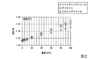
- FIG. 2 is a graph showing the relationship between the concentration of the polyhydric alcohol and the refractive index.
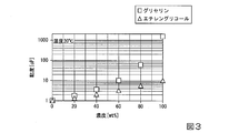
- FIG. 3 is a graph showing the relationship between the concentration of the polyhydric alcohol and the viscosity.
- FIG. 4 is a graph showing the relationship between the electric conductivity of the polyhydric alcohol and the weight concentration.
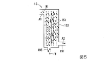
- FIG. 5 is a schematic view showing the configuration of the atomized droplet collecting portion.
- FIG. 6 is a schematic view showing another configuration of the atomized droplet collecting portion.
- FIG. 7 is a correlation diagram showing the composition conditions of the three components, and also shows the concentration ratio of the three components of the atomized solution W3, which is seawater (NaCl), water, and glycerin (polyhydric alcohol).
- FIG. 8 is a schematic diagram which shows the whole structure of the seawater desalination apparatus of 2nd Embodiment.
- FIG. 9 is a schematic view showing the overall configuration of the seawater desalination apparatus of the third embodiment.
- FIG. 10 is a schematic diagram showing the overall configuration of the seawater desalination apparatus of the fourth embodiment.
- FIG. 11 is an enlarged view showing the position of the sound wave generating portion.
- FIG. 1 is a schematic diagram showing the overall configuration of a seawater desalination apparatus 100 according to the first embodiment.
- FIG. 2 is a graph showing the relationship between the concentration of the polyhydric alcohol and the refractive index.
- FIG. 3 is a graph showing the relationship between the concentration of polyhydric alcohol and the viscosity.
- FIG. 4 is a graph showing the relationship between the electric conductivity of the polyhydric alcohol and the weight concentration.
- FIG. 5 is a schematic diagram showing the configuration of the atomized droplet recovery unit 15.
- FIG. 6 is a schematic diagram showing another configuration of the atomized droplet recovery unit 15.
- a seawater desalination apparatus 100 includes a seawater storage unit (storage unit) 11, an atomization separation unit 12, a filtration unit 13, a polyhydric alcohol storage unit (storage unit) 14, and atomization. It is configured to have a droplet collection unit 15, a management unit 16, a flow path system 19 and a control unit 3.
- the seawater storage unit 11 stores seawater W1.
- the main component of seawater W1 is sodium chloride, and the salinity is 3.5%.
- the seawater storage unit 11 is connected to the atomization separation unit 12 via the first supply flow path 19A, and is stored in the seawater storage unit 11 by driving the supply pump P1 arranged on the first supply flow path 19A.
- the separated seawater W1 is supplied to the atomization separation unit 12.
- the polyhydric alcohol storage unit 14 stores a predetermined polyhydric alcohol W2 added to the seawater W1.
- the polyhydric alcohol storage unit 14 is connected to the atomization separation unit 12 via the second supply flow path 19B, and the polyhydric alcohol storage unit 14 is driven by the supply pump P2 arranged on the second supply flow path 19B.
- the polyhydric alcohol W2 stored in the section 14 is supplied to the atomization separation section 12.
- glycerin is used as the polyhydric alcohol W2. Since glycerin is a component that is also used in lotions and the like, it has an advantage that it is easy to handle without any problems even if it is touched by humans.
- examples of the polyhydric alcohol W2 include propanediol, butanediol, pentanediol, trimethylolpropane, butanetriol, ethylene glycol, diethylene glycol, triethylene glycol and the like.
- glycerin, ethylene glycol, and triethylene glycol can be easily adjusted in viscosity, have high solubility in water, and can be separated from water.
- the atomization separation unit 12 includes at least an atomization separation tank (storage tank) 121 and an ultrasonic vibrator (ultrasonic generation unit) 122.
- an atomization separation tank (storage tank) 121 Into the internal space 121c of the atomization separation tank 121, the seawater W1 and the polyhydric water supplied from the seawater storage unit 11 and the polyhydric alcohol storage unit 14 through the first supply passage 19A and the second supply passage 19B, respectively.
- An atomization solution W3 made of a mixed liquid with alcohol W2 is stored.
- the first supply port (supply port) 121a to which the first supply flow path 19A is connected and the second supply port (supply port) to which the second supply flow path 19B is connected are connected.
- it has two supply ports with 121b, it is supplied when a confluence point between the first supply flow path 19A and the second supply flow path 19B is provided on the front stage side (upstream side) of the atomization separation tank 121. You may have one mouth.
- the ultrasonic vibrator 122 oscillates ultrasonic waves for generating a liquid column S.
- only one ultrasonic vibrator 122 is shown, but the number of ultrasonic vibrators 122 can be changed as appropriate, and a plurality of ultrasonic vibrators 122 may be provided.
- the ultrasonic transducer 122 is preferably provided so as to be inclined with respect to the bottom surface 121e of the atomization separation tank 121.
- the axis perpendicular to the ultrasonic irradiation surface 122a from the center of the ultrasonic irradiation surface 122a of the ultrasonic vibrator 122 is defined as the ultrasonic radiation axis J. Since the ultrasonic transducer 122 is inclined with respect to the bottom surface 121e of the atomization separation tank 121, the ultrasonic waves are irradiated with ultrasonic waves so that the radiation axis J is inclined with respect to the liquid surface 9 of the atomization solution W3. It is propagated from the surface 122a toward the liquid surface 9. This has the advantage that the ultrasonic waves reflected by the liquid surface 9 are less likely to return to the ultrasonic vibrator 122, and the ultrasonic vibrator 122 is less likely to be damaged by the ultrasonic waves.
- a liquid column S is formed on the liquid surface 9 of the atomized solution W3, and the liquid column S The water is separated from the surface of the to produce nano mist (atomized droplets).
- the liquid level 9 of the atomizing solution W3 has a predetermined height by adjusting the ultrasonic wave generation conditions such as the output and frequency of the ultrasonic waves.
- the liquid column S of the atomized solution W3 can be generated.
- the atomization separation unit 12 atomizes the atomization solution W3 obtained by adding the polyhydric alcohol to the seawater to generate the nanomist (atomization droplets) N that is substantially water, and then the seawater W1. At least a part of the contained water is atomized and separated.
- the generated nanomist N is sent to the atomized droplet collecting unit 15 via the flow path system 19.
- the “nanomist consisting essentially of water” is a mist having a water specific weight fraction of 99.9% or more.
- the management unit 16 includes a refractive index measuring device for measuring the refractive index of the atomizing solution W3 stored in the atomizing separation tank 121, a viscometer measuring device for measuring the viscosity of the atomizing solution W3, and electricity for the atomizing solution W3.
- a monitoring instrument 161 having at least an electric conductivity measuring instrument for measuring the conductivity is provided.
- the concentration of the polyhydric alcohol W2 in the atomized solution W3 can be identified by measuring the refractive index of the atomized solution W3 with the refractive index measuring device.
- the concentration of the polyhydric alcohol W2 in the atomized solution W3 can be identified by measuring the viscosity of the atomized solution W3 with the viscosity meter.
- the weight concentration of the salt (calcium chloride, lithium chloride) in the atomizing solution W3 tends to increase monotonically with respect to the electric conductivity, and the electric conductivity of the salt depends on the concentration. It fluctuates greatly. Therefore, it is possible to identify the salt concentration of the atomized solution W3 by providing the electric conductivity measuring device.
- the main component of seawater W1 is sodium chloride, but calcium chloride and lithium chloride are also included.
- the weight concentration of sodium chloride also tends to monotonically increase with respect to the electric conductivity.
- the monitoring instrument 161 provided with such a plurality of measuring instruments monitors the composition state of the atomizing solution W3 stored in the atomizing separation unit 12 and feeds it back to the control unit 3 at least during the atomizing operation. ..
- a database of the refractive index, viscosity, and electric conductivity of each composition of the atomizing solution W3 is constructed in advance, and the control unit 3 pumps according to the results of each measuring instrument in the monitoring instrument 161.
- the concentration ratio of water, sea water soluble matter (salt content), and polyhydric alcohol in the atomized solution W3 is managed.
- the management unit 16 in the present embodiment preferably includes a water level measurement unit 18 that measures the water level of the atomized solution W3 stored in the atomization separation tank 121.
- the water level of the atomization solution W3 may be adjusted according to the composition of the atomization solution W3 so as to maximize the atomization efficiency, or may be adjusted by the number of ultrasonic transducers 122, the output, and the like.
- the management unit 16 may separately include a stirring unit that stirs the atomized solution W3 stored in the atomization separation tank 121.
- the atomizing solution W3 is also agitated by the ultrasonic vibrator 122 described above, but the concentration unevenness of the polyhydric alcohol W2 can be further suppressed by actively agitating the atomizing solution W3 by the stirring unit 163.
- the first supply port (supply port) 121a in which the concentration of the polyhydric alcohol W2 tends to be lowered by the supplied seawater W1 and the polyhydric alcohol W2 supplied are used. It is preferable that the alcohol W2 is arranged at a location away from the second supply port (supply port) 121b where the concentration of the alcohol W2 tends to increase. Further, it is preferable to be arranged at a position away from the ultrasonic transducer 122 where the salt concentration is likely to increase due to atomization. For example, in the atomization separation tank 121, it is more preferable that the atomization separation tank 121 is provided in the vicinity of the above-mentioned stirring portion. Thereby, the composition of the atomized solution W3 can be measured more accurately.
- the filtration unit 13 is connected to the rear side of the atomization separation tank 121.
- the filtration unit 13 is connected to the atomization separation tank 121 via the discharge circulation flow path 19C and the supply circulation flow path 19D, and filters and deposits the atomization solution W3 stored in the atomization separation tank 121. It has the function of removing the salt.
- the removed salt E is recovered in the salt recovery unit 7 via the salt discharge flow path 19J connected to the filtration unit 13.
- the recovered salt E can be reused for other purposes.
- At least the discharge circulation flow path 19C is the bottom side of the atomization separation tank 121, and the liquid level of the atomization solution W3 stored in the atomization separation tank 121. It is provided at a position that is always lower than 9. Thereby, the atomized solution W3 can be efficiently taken out from the atomization separation tank 121 and filtered.
- control unit 3 individually operates the plurality of pumps P1, P2, P3, P4 provided in the flow path system 19 based on the previously constructed database. It is possible to control the composition of the atomized solution W3 by controlling and adjusting the supply amount, filtration speed, and drainage amount of seawater and polyhydric alcohol W2 stored in the atomization separation tank 121, respectively.
- the atomization separation tank 121 is connected to the atomization droplet collection unit 15 arranged on the rear side of the atomization separation tank 121.
- the atomized droplet collecting unit 15 collects the nanomist generated in the atomizing separation unit 12 and returns it to a liquid to obtain fresh water.
- the atomized droplet recovery unit 15 is connected to the atomization separation tank 121 via the mist delivery flow path 19G.
- the mist delivery flow path 19G is connected to a portion on the upper side of the wall portion 121d of the atomization separation tank 121 and always higher than the water level of the atomization solution W3 stored in the atomization separation tank 121. There is.
- the gas A1 containing the generated nanomist N can be efficiently sent out to the atomized droplet collecting unit 15 without causing the atomized solution W3 stored in the atomization separation tank 121 to flow in.
- a hydrophilic adsorbent 151 may be used as the atomized droplet collecting unit 15, for example, as shown in FIG. 5, a hydrophilic adsorbent 151 may be used.
- the hydrophilic adsorbent 151 is a dispersion of nanoporous silica particles or titania particles having high hydrophilicity for adsorbing water molecules, and a plurality of hydrophilic adsorbents 151 are provided in the housing 152.
- the gas A1 containing nanomist N sent from the atomization separation unit 12 flows between the plurality of hydrophilic adsorbents 151 arranged apart from each other, whereby in the above-mentioned nanopore silica particles and the like. Moisture is recovered and fresh water W is obtained.
- a freshwater storage tank 8 is connected to the subsequent stage of the atomized droplet collection unit 15 via a freshwater discharge flow path 19E, and in the freshwater storage tank 8, the freshwater W obtained by the atomized droplet collection unit 15 is It is stored. Further, the atomized droplet collecting unit 15 is connected to the atomizing separation tank 121 via the air supply flow path 19F, and the dry air A2 from which moisture has been removed and dehumidified is passed through the air supply flow path 19F. It is configured to be sent to the atomization separation unit 12.
- the atomized droplet collecting unit 15 is not limited to the configuration provided with the hydrophilic adsorbent 151.
- a plurality of fins 153 arranged at predetermined intervals and the plurality of fins 153 are provided.
- a configuration may be adopted in which the nanomist N is cooled by circulating the refrigerant in the heat exchange pipe 154 using the heat exchange pipe 154 arranged so as to straddle the heat exchange pipe 154 and the compressor 155 to obtain fresh water W.
- nanomist is liquefied by mechanical collision action such as sacron, chevron and demista to obtain fresh water.
- mechanical collision action such as sacron, chevron and demista to obtain fresh water.
- the cooling heat exchange action and the mechanical collision action may be combined.
- FIG. 7 is a correlation diagram showing the concentration ratios of the three components of the atomized solution W3: seawater (NaCl), water, and glycerin (polyhydric alcohol).
- the salt of seawater W1 is mainly composed of sodium chloride (NaCl).
- NaCl sodium chloride
- the inventor performed ultrasonic atomization of a sodium chloride aqueous solution having a seawater concentration of 3.5% and a sodium chloride aqueous solution having a saturation concentration of 26.5%, which reproduced seawater W1, and tested whether only water could be separated.
- Sodium chloride leaked into the generated micromist, and it was found that it was difficult to recover only water.
- FIG. 7 shows the range of the “micromist generation region R3”. Therefore, in order to ultrasonically atomize the sodium chloride aqueous solution to obtain fresh water, a separation process for further separating only water from the micromist is required in the subsequent stage.
- the seawater desalination apparatus 100 of one aspect of the present invention can adjust the concentration balance of the polyhydric alcohol W2 of the atomized solution W3 in the atomization separation unit 12.
- FIG. 7 shows the range of the “nanomist generation region R1”.
- composition condition of the atomized solution W3 in the “nano mist generation region R1" is referred to as "initial condition”.
- seawater desalination method Next, a seawater desalination method using the seawater desalination apparatus 100 will be described.
- the seawater W1 is supplied from the seawater storage unit 11 to the atomization separation tank 121 by driving the pumps P1 and P2 arranged on the first supply flow path 19A and the second supply flow path 19B,
- Polyhydric alcohol W2 such as glycerin is supplied from the polyhydric alcohol storage unit 14 to the atomization separation tank 121.
- the monitoring instrument 161 of the control unit 16 determines the refractive index, viscosity, and electrical conductivity of the mixed solution of seawater W1 and polyhydric alcohol W2 supplied into the atomization separation tank 121, that is, the atomization solution W3. Measure and monitor the concentration of polyhydric alcohol W2. Seawater W1 and polyhydric alcohol W2 are supplied until the composition of the atomizing solution W3 reaches the above-mentioned "initial conditions".
- the fan 17 provided in the air supply flow path 19F is driven to supply air into the atomization separation tank 121, and the liquid column is supplied.
- nanomist N is generated.
- the generated nanomist N is almost composed of water, and only water is separated from the atomized solution W3.
- the gas A1 containing the generated nanomist N is sent to the atomized droplet collection unit 15 via the mist delivery flow path 19G.
- the atomized droplet collecting unit 15 when the gas A1 passes between the plurality of arranged hydrophilic adsorbents 151, the nanomist N contained in the gas A1 is adsorbed by a large number of nanopore silica particles.
- the fresh water W that has been collected and turned into a liquid is discharged to the fresh water storage tank 8 through the fresh water discharge flow path 19E and collected.
- the dry air that has been dehumidified by removing water in the atomized droplet recovery unit 15 is sent to the atomization separation unit 12 via the air supply flow path 19F.
- the concentration ratio of each composition in the atomized solution W3 is monitored by the monitoring instrument 161 and the seawater W1 is constantly supplied and supplied from the seawater storage unit 11 to the atomization separation tank 121.
- the polyhydric alcohol W2 corresponding to the amount of the seawater W1 is appropriately supplied from the polyhydric alcohol storage unit 14.
- the composition of the atomizing solution W3 is an "unsaturated region" even in the "initial conditions". It is limited to the boundary line K with "R2".
- Nanomist N produced by ultrasonic atomization contains almost no seawater, and almost freshwater mist is generated.
- the seawater desalination apparatus 100 of the present embodiment by adding the polyhydric alcohol W2 to the seawater, it is possible to generate nanomist N almost composed of water at the stage of ultrasonic atomization. Therefore, it is not necessary to further separate the fresh water from the mist by using the conventional separation device, and it becomes possible to recover the fresh water more efficiently with energy saving.
- the control unit 16 constantly monitors the composition of the atomized solution W3, and the concentration ratio of the seawater-soluble substance and the polyhydric alcohol W2 is kept in the "nano mist generation region R1".
- the liquid column S is satisfactorily formed in the atomization separation section 12, and the production efficiency of nanomist N by atomization Can be enhanced.
- the seawater desalination apparatus 100 can be continuously operated while maintaining the atomization efficiency, a large amount of seawater W1 can be efficiently desalinated.
- the seawater storage unit 11 and the multivalent alcohol storage unit 14 are provided, respectively, and the atomization separation unit 12 mixes the seawater W1 and the multivalent alcohol W2.
- the initial condition liquid supply unit in which the polyhydric alcohol W2 is mixed in advance and the initial condition liquid adjusted to the “initial condition” is stored may be provided in place of the seawater storage unit 11 and the polyhydric alcohol storage unit 14.
- the flow path system 19 of the present embodiment has an atomized solution discharge flow path (discharge flow path) 19H for discharging the atomized solution W3 from the atomization separation unit 12.
- discharge flow path discharge flow path
- the concentration ratio of the seawater-soluble substance and the polyhydric alcohol W2 in the atomizing solution W3 can be controlled more efficiently.
- seawater desalination apparatus 200 of the second embodiment of the present invention will be described.
- the basic configuration of the seawater desalination device 200 of the present embodiment shown below is substantially the same as that of the first embodiment, except that the heating device 21 is provided. Therefore, in the following description, points different from the previous embodiment will be described in detail, and description of common points will be omitted. Moreover, in each drawing used for the description, the same reference numerals are given to the constituent elements common to the above-described embodiment.
- FIG. 8 is a schematic diagram which shows the whole structure of the seawater desalination apparatus 200 of 2nd Embodiment.
- the seawater desalination apparatus 200 of the present embodiment includes a seawater storage unit 11, an atomization separation unit 12, a filtration unit 13, a polyhydric alcohol storage unit 14, an atomized droplet collection unit 15, a management unit 16, a flow path system 19, and The controller 3 is provided, and the heating device 21 is further provided.
- the warming device 21 is arranged on the first supply flow path 19A between the seawater storage unit 11 and the atomization separation unit 12, and heats the seawater W1 supplied from the seawater storage unit 11 to the atomization separation unit 12. To do.
- the heating device 21 in the present embodiment uses, for example, solar heat, but is not limited to this.
- the heating device 21 may be arranged on the second supply flow path 19B between the polyhydric alcohol W2 and the atomization separation unit 12. Both the seawater W1 and the polyhydric alcohol W2 may be heated, or only one of them may be heated.
- a heating device 21 may be added to the atomization separation unit 12 to heat the atomization solution W3.
- a heating device 21 may be added to the atomization separation unit 12 to heat the atomization solution W3.
- FIG. 9 is a schematic diagram showing the overall configuration of the seawater desalination apparatus 300 of the third embodiment.
- the seawater desalination apparatus 300 of this embodiment includes a seawater storage unit 11, an atomization separation unit 12, a filtration unit 13, a polyhydric alcohol storage unit 14, an atomized droplet collection unit 15, a management unit 16, a flow path system 19, and
- the heat pump 31 is further provided in addition to the control unit 3.
- the atomized droplet collecting unit 15 of the present embodiment collects nanomist N as droplets by a cooling action in the cooling unit 33 of the heat pump 31 to obtain fresh water.
- the gas containing nanomist N is cooled by circulating the refrigerant through the heat exchange pipe 154 as shown in FIG. 6, and in the present embodiment, the cooling heat (endothermic) obtained at this time is used. Then, the seawater W1 is heated.
- the temperature of the refrigerant is raised by compressing the refrigerant with the compressor 34, and the heated refrigerant is supplied to the heating unit 32 and circulated through the heat exchange pipe 154 to move from the seawater storage unit 11 to the atomization separation unit 12.
- the seawater W1 to be sent is heated.
- the nano mist N can be efficiently liquefied by utilizing the respective actions of the heating unit 32 and the cooling unit 33 of the heat pump 31, and the cooling heat at this time is used to heat the seawater W1. , Energy saving can improve atomization efficiency.
- FIG. 10 is a schematic diagram which shows the whole structure of the seawater desalination apparatus 400 of 4th Embodiment.
- FIG. 11 is an enlarged view showing the arrangement position of the sound wave generator 41.
- the seawater desalination apparatus 400 of the present embodiment includes a seawater storage unit 11, an atomization separation unit 12, a filtration unit 13, a polyhydric alcohol storage unit 14, an atomized droplet collection unit 15, a management unit 16, a flow path system 19, and A control unit 3 and a heat pump 31 are provided, and a sound wave generating unit 41 is further provided.
- a sound wave generating unit 41 is provided on the mist sending flow path 19G between the atomizing separation unit 12 and the atomized droplet collecting unit 15 with respect to the gas A1 containing nanomist N.
- nanomist N can be coarsened by vibration of sound.
- the nanomist can be aggregated in the region shown by the alternate long and short dash line in FIG. 11, and the atomized droplet collecting unit 15 is supplied with the gas containing the mist coarsened in this way. It is possible to save energy in the process of recovering fresh water at 15.
- a speaker as the sound wave generating unit 41, for example, to generate a sound wave having a sound range of 100 to 1000 Hz.
Landscapes
- Engineering & Computer Science (AREA)
- Chemical & Material Sciences (AREA)
- Hydrology & Water Resources (AREA)
- Life Sciences & Earth Sciences (AREA)
- Environmental & Geological Engineering (AREA)
- Water Supply & Treatment (AREA)
- Mechanical Engineering (AREA)
- Organic Chemistry (AREA)
- Chemical Kinetics & Catalysis (AREA)
- Heat Treatment Of Water, Waste Water Or Sewage (AREA)
- Separation Using Semi-Permeable Membranes (AREA)
- Physical Water Treatments (AREA)
- Vaporization, Distillation, Condensation, Sublimation, And Cold Traps (AREA)
Abstract
省エネルギーで効率よく海水を淡水化できる海水淡水化装置および海水淡水化方法を提供する。海水淡水化装置は、海水と多価アルコールとの混合液からなる霧化溶液を霧化させて、ほぼ水からなる霧化液滴を生成する霧化分離部と、霧化分離部に供給する海水および多価アルコールを貯留する貯留部と、霧化液滴を回収する霧化液滴回収部と、を備え、霧化分離部は、混合液を貯留する霧化分離槽と、霧化分離槽に設けられ、霧化溶液に対して超音波を照射する超音波発生部と、を有している。
Description
本発明は、海水淡水化装置および海水淡水化方法に関するものである。
本願は、2019年3月6日に日本で出願された特願2019-40458号に基づき優先権を主張し、その内容をここに援用する。
本願は、2019年3月6日に日本で出願された特願2019-40458号に基づき優先権を主張し、その内容をここに援用する。
従来、海水淡水化技術として、加熱蒸発させた水蒸気を凝縮させる蒸留法や、水分子のみを選択透過させる逆浸透膜法が適用されているが、蒸留法の場合は、潜熱変換による消費エネルギーが大きく、逆浸透膜法の場合は、イニシャルコストがかかるとともに高圧プロセスのため大規模装置に用途限定されるといった課題があった。
そこで、海水を霧化し、霧中のナノミストのみを分離した後、液体を回収することで淡水を得る方法が存在する(例えば、特許文献1,2)。
そこで、海水を霧化し、霧中のナノミストのみを分離した後、液体を回収することで淡水を得る方法が存在する(例えば、特許文献1,2)。
特許文献1では、海水を霧化した後、霧化微粒子のみを分離して冷却凝縮し、淡水を回収する技術が開示されています。また、特許文献2では、静電霧化して海水を搬送気体中にミストに霧化すると共に、霧化されたミストを粒径でミスト分級器で分級して、塩分を含まない極めて微細なミストを回収して淡水を得る技術が開示されています。
しかしながら、従来の方法では、マイクロサイズの霧化液滴が生成される。マイクロミスト中には海水成分が漏洩しているため、淡水のみを分離させる分離プロセスが別途必要になる。この分離プロセス時にマイクロミストが蒸発してしまい、後段での淡水回収効率を低下させてしまうという問題があった。また、蒸発して気体の状態になった水蒸気を再び液体に戻すために冷却凝縮による回収プロセスが必要になり、その分のエネルギーロスが大きくなってしまう。さらに、引用文献1,2では、霧に海水成分が漏洩している可能性が高く、淡水のみを回収するのは難しい。
本発明の一つの態様は、上記従来技術の問題点に鑑み成されたものであって、省エネルギーで効率よく海水を淡水化できる海水淡水化装置および海水淡水化方法を提供することを目的とする。
本発明における一態様の海水淡水化装置は、海水と多価アルコールとの混合液からなる霧化溶液を霧化させて、ほぼ水からなる霧化液滴を生成する霧化分離部と、前記霧化分離部に供給する前記海水および前記多価アルコールを貯留する貯留部と、前記霧化液滴を回収する霧化液滴回収部と、を備え、前記霧化分離部は、前記霧化溶液を貯留する霧化分離槽と、前記霧化分離槽に設けられ、前記霧化溶液に対して超音波を照射する超音波発生部と、を有している。
本発明の一態様の海水淡水化装置において、前記霧化分離部内の前記霧化溶液を濾過して析出した塩を除去する濾過部を備えている構成としてもよい。
本発明の一態様の海水淡水化装置において、前記霧化分離部に貯留された前記霧化溶液における水、海水溶質および前記多価アルコールの濃度比を管理する管理部を備えている構成としてもよい。
本発明の一態様の海水淡水化装置において、前記霧化分離槽は、前記貯留部から前記海水および前記多価アルコールが供給される供給口を有し、前記管理部は、前記供給口および前記超音波発生部から離れたところに設けられている構成としてもよい。
本発明の一態様の海水淡水化装置において、前記管理部は、前記霧化溶液の屈折率を測定する屈折率測定器と、前記霧化溶液の粘度を測定する粘度測定器と、前記霧化溶液に対する電気伝導率を測定する電気伝導率測定器と、を有する構成としてもよい。
本発明の一態様の海水淡水化装置において、少なくとも、前記霧化分離部、前記貯留部および前記霧化液滴回収部を接続する流路系を有し、前記流路系は、前記霧化分離部から前記霧化溶液を排出する排出流路を有している構成としてもよい。
本発明の一態様の海水淡水化装置において、前記海水あるいは前記霧化溶液を加温する加温装置を備えている構成としてもよい。
本発明の一態様の海水淡水化装置において、前記加温装置は、加熱部および冷却部を有するヒートポンプを備え、前記加熱部により前記海水あるいは前記霧化溶液を加熱し、前記冷却部により前記霧化液滴を冷却する構成としてもよい。
本発明の一態様の海水淡水化装置において、前記霧化分離部と前記霧化液滴回収部との間に、前記霧化液滴に対して音波を照射する音波発生部が配置されている構成としてもよい。
本発明における一態様の海水淡水化方法は、霧化分離部において海水と多価アルコールとの混合液からなる霧化溶液を霧化させてほぼ水からなる霧化液滴を生成するとともに、前記霧化分離部に前記海水および前記多価アルコールを供給する工程と、前記霧化液滴を回収する工程と、を備えており、前記霧化分離部では、霧化分離槽に貯留された前記霧化溶液に対して超音波を照射し、前記霧化溶液の液面に液柱を形成することで前記霧化液滴を生成している、海水淡水化方法。
本発明の一態様の海水淡水化方法は、前記霧化分離部内の前記霧化溶液を濾過する工程を有している方法としてもよい。
本発明の一態様の海水淡水化方法は、前記霧化液滴の生成中は前記霧化溶液の組成を管理し、前記霧化分離部に対する前記海水および前記多価アルコールの供給比率を調整する方法としてもよい。
本発明の一態様の海水淡水化方法は、前記海水あるいは前記霧化溶液を加熱して霧化を行う方法としてもよい。
本発明の一態様の海水淡水化方法は、前記霧化液滴に対して音波を照射することで液滴にする方法としてもよい。
本発明の一態様によれば、省エネルギーで効率よく海水を淡水化できる海水淡水化装置および海水淡水化方法を提供することができる。
[第1実施形態]
以下、本発明の第1実施形態の海水淡水化装置100について説明する。
なお、以下の各図面においては、各構成要素を見やすくするため、構成要素によって寸法の縮尺を異ならせて示すことがある。
以下、本発明の第1実施形態の海水淡水化装置100について説明する。
なお、以下の各図面においては、各構成要素を見やすくするため、構成要素によって寸法の縮尺を異ならせて示すことがある。
図1は、第1実施形態における海水淡水化装置100の全体構成を示す概略図である。図2は、多価アルコールの濃度と屈折率との関係を示すグラフである。図3は、多価アルコールの濃度と粘度の関係を示すグラフである。図4は、多価アルコールの電気伝導率と重量濃度との関係を示すグラフである。図5は、霧化液滴回収部15の構成を示す概略図である。図6は、霧化液滴回収部15の他の構成を示す概略図である。
図1に示すように、本実施形態の海水淡水化装置100は、海水貯留部(貯留部)11、霧化分離部12、濾過部13、多価アルコール貯留部(貯留部)14、霧化液滴回収部15、管理部16、流路系19および制御部3を有して構成されている。
海水貯留部11は、海水W1を貯留する。海水W1の主成分は塩化ナトリウムであり、塩分濃度は3.5%である。海水貯留部11は、第1供給流路19Aを介して霧化分離部12に接続されており、第1供給流路19A上に配置された供給ポンプP1の駆動によって、海水貯留部11に貯留された海水W1が霧化分離部12へと供給されるようになっている。
多価アルコール貯留部14は、海水W1に添加する所定の多価アルコールW2を貯留する。多価アルコール貯留部14は、第2供給流路19Bを介して霧化分離部12に接続されており、第2供給流路19B上に配置された供給ポンプP2の駆動によって、多価アルコール貯留部14に貯留された多価アルコールW2が霧化分離部12へと供給されるようになっている。
本実施形態では、多価アルコールW2として、例えばグリセリンを用いている。グリセリンは、化粧水等にも用いられる成分であるため、人が触れても問題はなく扱いやすいという利点がある。これ以外にも、多価アルコールW2として、プロパンジオール、ブタンジオール、ペンタンジオール、トリメチロールプロパン、ブタントリオール、エチレングリコール、ジエチレングリコール、トリエチレングリコール等が挙げられる。これら多価アルコールW2のなかでも、グリセリン、エチレングリコール、トリエチレングリコールは、粘度調整が容易で水との溶解度も高く、水との分離も可能である。
霧化分離部12は、霧化分離槽(貯留槽)121と超音波振動子(超音波発生部)122とを少なくとも備えている。
霧化分離槽121の内部空間121cには、これら海水貯留部11および多価アルコール貯留部14のそれぞれから第1供給流路19Aおよび第2供給流路19Bを通じて供給される、海水W1と多価アルコールW2との混合液からなる霧化溶液W3が貯留される。
霧化分離槽121の内部空間121cには、これら海水貯留部11および多価アルコール貯留部14のそれぞれから第1供給流路19Aおよび第2供給流路19Bを通じて供給される、海水W1と多価アルコールW2との混合液からなる霧化溶液W3が貯留される。
本実施形態の霧化分離槽121は、第1供給流路19Aが接続される第1供給口(供給口)121aと、第2供給流路19Bが接続される第2供給口(供給口)121bとの2つの供給口を有しているが、霧化分離槽121よりも前段側(上流側)に第1供給流路19Aと第2供給流路19Bとの合流点を設ける場合は供給口を1つにしてもよい。
超音波振動子122は、液柱Sを発生させるための超音波を発振する。本実施形態では、1つの超音波振動子122のみ図示しているが、超音波振動子122の数は適宜変更でき、複数設けてもよい。
超音波振動子122は、霧化分離槽121の底面121eに対して傾斜して設けられていることが好ましい。超音波振動子122の超音波照射面122aの中心から超音波照射面122aに対して垂直な軸を超音波の放射軸Jと定義する。超音波振動子122が霧化分離槽121の底面121eに対して傾斜していることにより、超音波は、放射軸Jが霧化溶液W3の液面9に対して傾くように、超音波照射面122aから液面9に向けて伝搬される。これにより、液面9で反射した超音波が超音波振動子122に戻りにくくなり、超音波振動子122が超音波によるダメージを受けにくくなるという利点がある。
霧化分離槽121に貯留されている霧化溶液W3に対して超音波振動子122から超音波が照射されると、霧化溶液W3の液面9に液柱Sが形成され、液柱Sの表面から水分が分離されてナノミスト(霧化液滴)が発生する。超音波振動子122から霧化溶液W3に超音波が照射される際、超音波の出力および周波数など、超音波発生条件を調整することにより、霧化溶液W3の液面9に所定の高さの霧化溶液W3の液柱Sを生じさせることができる。
本実施形態では、霧化分離部12において、海水に多価アルコールを添加してなる霧化溶液W3を霧化させてほぼ水からなるナノミスト(霧化液滴)Nを生成し、海水W1に含まれる水分の少なくとも一部を霧化分離する。生成されたナノミストNは、流路系19を介して霧化液滴回収部15へと送られる。
ここで、「ほぼ水からなるナノミスト」とは、水比重量分率が99.9%以上のミストである。
ここで、「ほぼ水からなるナノミスト」とは、水比重量分率が99.9%以上のミストである。
管理部16は、霧化分離槽121に貯留された霧化溶液W3の屈折率を測定する屈折率測定器と、霧化溶液W3の粘度を測定する粘度測定器と、霧化溶液W3に対する電気伝導率を測定する電気伝導率測定器と、を少なくとも有するモニタリング計器161を備えている。
図2に示すように、多価アルコールW2において、屈折率はその濃度に対して単調に増加する傾向にあり、多価アルコールW2の濃度によって霧化溶液W3の屈折率が変動する。このため、屈折率測定器により霧化溶液W3の屈折率を測定することで、霧化溶液W3における多価アルコールW2の濃度を識別することが可能となる。
また、図3に示すように、多価アルコールW2において、粘度はその濃度に対して単調に増加する傾向にあり、多価アルコールW2の濃度によって霧化溶液W3の粘度が変動する。このため、粘度測定器によって霧化溶液W3の粘度を測定することで、霧化溶液W3における多価アルコールW2の濃度を識別することが可能となる。
さらに、図4に示すように、霧化溶液W3における塩分(塩化カルシウム、塩化リチウム)の重量濃度は、その電気伝導率に対して単調に増加する傾向にあり、塩分は濃度によって電気伝導率が大きく変動する。このため、電気伝導率測定器を設けることによって霧化溶液W3の塩分濃度を識別することが可能となる。海水W1の主成分は塩化ナトリウムであるが、塩化カルシウム、塩化リチウムも含まれる。図4には記載していないが、塩化ナトリウムにおいても重量濃度は電気伝導率に対して単調に増加する傾向にある。
このような複数の測定器を備えたモニタリング計器161は、少なくとも霧化動作中において、霧化分離部12内に貯留されている霧化溶液W3の組成状態をモニタリングし、制御部3にフィードバックする。本実施形態では、霧化溶液W3の各組成における屈折率、粘度、電気伝導率のデータベースを予め構築しておき、モニタリング計器161における各測定器によるそれぞれの結果に応じて、制御部3においてポンプP1,P2,P3,P4の出力を制御することにより、霧化溶液W3における水、海水溶質(塩分)、多価アルコールの濃度比を管理している。
本実施形態における管理部16は、霧化分離槽121内に貯留されている霧化溶液W3の水位を測定する水位測定部18を備えていることが好ましい。霧化溶液W3の水位は、霧化効率が最大になるように霧化溶液W3の組成に応じて調整してもよいし、超音波振動子122の数、出力等によって調整してもよい。
また、管理部16は、霧化分離槽121内に貯留されている霧化溶液W3を撹拌する撹拌部を別途備えていてもよい。上述した超音波振動子122によっても霧化溶液W3は撹拌されるが、撹拌部163によって霧化溶液W3を積極的に撹拌することで、多価アルコールW2の濃度ムラをより抑えることができる。
モニタリング計器161は、霧化分離槽121のうち、供給される海水W1によって多価アルコールW2の濃度が低くなりやすい第1供給口(供給口)121aや、供給される多価アルコールW2によって多価アルコールW2の濃度が高まりやすい第2供給口(供給口)121bから離れたところに配置されていることが好ましい。また、霧化によって塩分濃度が高まりやすい超音波振動子122からも離れたところに配置されていることが好ましい。例えば、霧化分離槽121のうち、上述した撹拌部の近傍に設けられていることがより好ましい。これにより、霧化溶液W3の組成をより正確に測定することができる。
霧化分離槽121の後段側には、濾過部13が接続されている。
濾過部13は、排出循環流路19Cおよび供給循環流路19Dを介して霧化分離槽121に接続されており、霧化分離槽121内に貯留されている霧化溶液W3を濾過して析出した塩を取り除く機能を有する。取り除いた塩Eは、濾過部13に接続された塩排出流路19Jを介して塩回収部7において回収される。回収した塩Eは他の用途において再利用することも可能である。
濾過部13は、排出循環流路19Cおよび供給循環流路19Dを介して霧化分離槽121に接続されており、霧化分離槽121内に貯留されている霧化溶液W3を濾過して析出した塩を取り除く機能を有する。取り除いた塩Eは、濾過部13に接続された塩排出流路19Jを介して塩回収部7において回収される。回収した塩Eは他の用途において再利用することも可能である。
排出循環流路19Cおよび供給循環流路19Dのうち少なくとも排出循環流路19Cは、霧化分離槽121の底部側であって、霧化分離槽121内に貯留される霧化溶液W3の液面9よりも常に下位になる箇所に設けられる。これにより、霧化分離槽121内から霧化溶液W3を効率よく取り出して濾過を行うことができる。
制御部3は、管理部16から計測結果がフィードバックされると、予め構築しておいた上記データベースに基づいて、流路系19に設けられた複数のポンプP1,P2,P3,P4を個々に制御し、霧化分離槽121内に貯留する海水および多価アルコールW2の供給量、濾過スピード、排水量をそれぞれ調整することで、霧化溶液W3の組成を管理することが可能である。
霧化分離槽121には、これよりも後段側に配置された霧化液滴回収部15が接続されている。霧化液滴回収部15では、霧化分離部12において生成されたナノミストを回収し、液体に戻すことで淡水を得ている。霧化液滴回収部15は、ミスト送出流路19Gを介して霧化分離槽121に接続されている。ミスト送出流路19Gは、霧化分離槽121の壁部121dの上部側であって、霧化分離槽121内に貯留される霧化溶液W3の水位よりも常に上位になる箇所に接続されている。これにより、霧化分離槽121内に貯留された霧化溶液W3を流入させることなく、生成されたナノミストNを含む気体A1を効率よく霧化液滴回収部15へ送り出すことができる。
霧化液滴回収部15としては、例えば、図5に示すように、親水性吸着材151を利用した構成としてもよい。親水性吸着材151は、水分子を吸着させる親水性能の高いナノ細孔シリカ粒子やチタニア粒子が分散されたもので、筐体152内に複数設けられている。互いに離間して配置された複数の親水性吸着材151どうしの間を、霧化分離部12から送られてきたナノミストNを含む気体A1が流動することで、上述したナノ細孔シリカ粒子等において水分が回収され、淡水Wが得られる。
霧化液滴回収部15の後段には淡水排出流路19Eを介して淡水貯留槽8が接続されており、当該淡水貯留槽8において、霧化液滴回収部15で得られた淡水Wが貯留される。さらに、霧化液滴回収部15は、空気供給流路19Fを介して霧化分離槽121に接続されており、水分が除去されて除湿された乾燥空気A2を、空気供給流路19Fを介して霧化分離部12へと送られる構成となっている。
霧化液滴回収部15は、親水性吸着材151を備えた構成に限られず、例えば、図6に示すように、所定の間隔で配置された複数のフィン153と、これら複数のフィン153を跨ぐようにして配置された熱交換パイプ154と、コンプレッサー155とを用いて、熱交換パイプ154で冷媒を循環させることによってナノミストNを冷却し、淡水Wを得る構成を採用してもよい。
また、サクロン、シェブロンおよびデミスタなどの機械衝突作用によってナノミストを液体化し、淡水を得る構成を採用してもよい。
なお、冷却熱交換作用と機械衝突作用とを組み合わせた構成にしてもよい。
なお、冷却熱交換作用と機械衝突作用とを組み合わせた構成にしてもよい。
次に、海水淡水化装置100の運転時における霧化溶液W3の組成条件について述べる。
図7は、霧化溶液W3の海水溶質(NaCl)、水、グリセリン(多価アルコール)の三成分の濃度比を示す相関図である。
図7は、霧化溶液W3の海水溶質(NaCl)、水、グリセリン(多価アルコール)の三成分の濃度比を示す相関図である。
海水W1の塩分は、塩化ナトリウム(NaCl)が主成分である。発明者は、海水W1を再現した海水濃度3.5%の塩化ナトリウム水溶液、飽和濃度26.5%の塩化ナトリウム水溶液に対してそれぞれ超音波霧化を行い、水だけを分離できるか試したが、生成されるマイクロミスト中には塩化ナトリウムが漏洩してしまい、水だけを回収するのは難しいことが分かった。図7に「マイクロミスト発生領域R3」の範囲を示す。
このため、塩化ナトリウム水溶液を超音波霧化して淡水を得るためには、マイクロミストからさらに水のみを分離する分離プロセスが後段において必要となってしまう。
このため、塩化ナトリウム水溶液を超音波霧化して淡水を得るためには、マイクロミストからさらに水のみを分離する分離プロセスが後段において必要となってしまう。
そこで、発明者は、塩化ナトリウム水溶液(海水)に多価アルコールW2を混合することで三成分系にし、霧化溶液W3の粘度をうまく調整できる状態にして霧化を行ったところ、ほぼ水のみからなるナノミストNを生成することが可能となり、水だけを分離して回収することができた。このように、水だけを回収するためには、霧化溶液W3の組成条件が重要となる。本発明の一態様の海水淡水化装置100は、霧化分離部12における霧化溶液W3の多価アルコールW2の濃度バランスを調整することが可能である。
そこで、塩化ナトリウム水溶液に対してグリセリンを加えていくと、ある領域からマイクロミストが減少し、ナノミストNが多く生成されるようになった。つまり、霧化溶液W3におけるグリセリンの割合が増えていくと、生成されるミストに漏洩する塩化ナトリウムの量が少なくなって、ほぼ水のみからなるナノミストNだけを生成することができた。図7に「ナノミスト発生領域R1」の範囲を示す。
海水W1から淡水Wを得るためには、海水淡水化装置100の運転中、霧化溶液W3の組成条件を、上述した「ナノミスト発生領域R1」内に維持することが重要である。この「ナノミスト発生領域R1」における霧化溶液W3の組成条件を「初期条件」とする。
(海水淡水化方法)
次に、海水淡水化装置100を用いた海水淡水化方法について述べる。
まず、第1供給流路19Aおよび第2供給流路19B上に配置されたポンプP1,P2を駆動させることで、海水貯留部11から霧化分離槽121に対して海水W1を供給するとともに、多価アルコール貯留部14から霧化分離槽121に対してグリセリンなどの多価アルコールW2を供給する。
次に、海水淡水化装置100を用いた海水淡水化方法について述べる。
まず、第1供給流路19Aおよび第2供給流路19B上に配置されたポンプP1,P2を駆動させることで、海水貯留部11から霧化分離槽121に対して海水W1を供給するとともに、多価アルコール貯留部14から霧化分離槽121に対してグリセリンなどの多価アルコールW2を供給する。
このとき、管理部16のモニタリング計器161によって、霧化分離槽121内に供給された海水W1と多価アルコールW2との混合液、つまり、霧化溶液W3における屈折率、粘度、電気伝導率を計測し、多価アルコールW2の濃度をモニタリングする。霧化溶液W3の組成が上述した「初期条件」になるまで、海水W1および多価アルコールW2の供給を行う。
次に、超音波振動子122を駆動することで、霧化分離槽121内に貯留された初期条件の霧化溶液W3に対して超音波を照射し、液柱Sを形成することで、霧化溶液W3を高く持ち上げる。
また、超音波振動子122を駆動させるのとほぼ同時期に、空気供給流路19F内に被設けられたファン17を駆動させることで、霧化分離槽121内に空気を供給し、液柱Sに接触させることでナノミストNを生じさせる。生成されるナノミストNはほぼ水からなり、霧化溶液W3から水のみが分離される。
生成されたナノミストNを含む気体A1は、ミスト送出流路19Gを介して霧化液滴回収部15へと送られる。霧化液滴回収部15において、複数配列された親水性吸着材151どうしの間を上記気体A1が通過する際に、気体A1に含まれるナノミストNが多数のナノ細孔シリカ粒子に吸着されて集められ、液体となった淡水Wは淡水排出流路19Eを介して淡水貯留槽8に排出されて回収される。
一方、霧化液滴回収部15において水分が除去されて除湿された乾燥空気は、空気供給流路19Fを介して霧化分離部12へと送られる。
海水淡水化装置100では、連続運転によって霧化分離を継続していくと、霧化溶液W3から水分が徐々に分離されて組成条件が初期条件から変動してくる。
霧化溶液W3の組成が「初期条件」から外れてしまうと、水のみを分離、回収するのが難しくなってしまう。また、霧化溶液W3の組成が「初期条件」から外れていなくても、水の分離、回収に伴って塩分濃度が高まり、霧化溶液W3の組成バランスが変動して図2に示す「不飽和領域R2」との境界ラインK上に到達すると、液柱SによってナノミストNが生成されるのと同時に塩が析出されるという現象が生じる。つまり、霧化溶液W3における塩分濃度が高い状況下で液柱Sが形成されると、部分的にさらに高濃度になっていくので、局所的に塩が析出される。そのため、析出した塩を常に濾過しながら霧化を行わなければならず、霧化効率が低下してしまう。
そのため、霧化を行っている間、モニタリング計器161によって霧化溶液W3における各組成の濃度比率をモニタリングし、海水貯留部11から海水W1を霧化分離槽121へ定常的に供給するとともに、供給した海水W1の量に対応する多価アルコールW2を多価アルコール貯留部14から適宜供給する。
一方、多価アルコールW2を供給することなく海水W1のみを定常的に供給し、濾過を行いながら霧化を行う場合は、霧化溶液W3の組成が、「初期条件」の中でも「不飽和領域R2」との境界ラインK上に制限されてしまう。
そのため、「初期条件」の中でより霧化効率を高めたい場合は、霧化溶液W3の組成が「不飽和領域R2」との境界ラインK側に傾いてきたときに、所定量の多価アルコールW2を供給する。このとき、多価アルコールW2の供給量だけでなく、海水W1の供給量、超音波の出力、濾過スピードも管理することで、霧化溶液W3の組成を、上記境界ラインK上の条件から離れる方向、例えば、図7に示した「ナノミスト発生領域R1」の中央に向かう方向へ戻しながら霧化を行う。
超音波霧化によって生成されるナノミストNには、海水溶質がほとんど含まれておらず、ほぼ淡水のミストが生成される。
このように、本実施形態の海水淡水化装置100によれば、海水に多価アルコールW2を添加することで、超音波霧化を行った段階でほぼ水からなるナノミストNを生成することができることから、従来のような分離装置を用いてミストから淡水をさらに分離する必要もなくなり、省エネルギーでより効率よく淡水を回収することが可能となる。
また、装置運転中、管理部16により霧化溶液W3の組成を常時モニタリングしながら、海水溶質および多価アルコールW2の濃度比を「ナノミスト発生領域R1」に留めるよう、海水と多価アルコールとの供給比率および濾過スピード等を制御し、霧化溶液W3の組成を「初期条件」に維持することによって、霧化分離部12において液柱Sが良好に形成され、霧化によるナノミストNの生成効率を高めることができる。このように、霧化効率を維持しながら海水淡水化装置100を連続運転することが可能なため、多量の海水W1を効率よく淡水化することができる。
なお、本実施形態では、海水貯留部11および多価アルコール貯留部14をそれぞれ備え、霧化分離部12において海水W1と多価アルコールW2とが混合される構成となっているが、海水W1および多価アルコールW2を予め混合させておき、「初期条件」に調整した初期条件液を貯留する初期条件液供給部を、海水貯留部11および多価アルコール貯留部14に代えて設けてもよい。
また、本実施形態の流路系19は、霧化分離部12から霧化溶液W3を排出する霧化溶液排出流路(排出流路)19Hを有している。霧化分離部12からの霧化溶液W3の排出量を調整することによって、霧化溶液W3における海水溶質と多価アルコールW2との濃度比をより効率よく管理することができる。
[第2実施形態]
次に、本発明の第2実施形態の海水淡水化装置200について説明する。
以下に示す本実施形態の海水淡水化装置200の基本構成は、上記第1実施形態と略同様であるが、加温装置21を備えた点において異なる。よって、以下の説明では、先の実施形態と異なる点について詳しく説明し、共通な箇所の説明は省略する。また、説明に用いる各図面において、先の実施形態と共通する構成要素には同一の符号を付すものとする。
次に、本発明の第2実施形態の海水淡水化装置200について説明する。
以下に示す本実施形態の海水淡水化装置200の基本構成は、上記第1実施形態と略同様であるが、加温装置21を備えた点において異なる。よって、以下の説明では、先の実施形態と異なる点について詳しく説明し、共通な箇所の説明は省略する。また、説明に用いる各図面において、先の実施形態と共通する構成要素には同一の符号を付すものとする。
図8は、第2実施形態の海水淡水化装置200の全体構成を示す概略図である。
本実施形態の海水淡水化装置200は、海水貯留部11、霧化分離部12、濾過部13、多価アルコール貯留部14、霧化液滴回収部15、管理部16、流路系19および制御部3を備えるとともに、さらに加温装置21を備えている。
本実施形態の海水淡水化装置200は、海水貯留部11、霧化分離部12、濾過部13、多価アルコール貯留部14、霧化液滴回収部15、管理部16、流路系19および制御部3を備えるとともに、さらに加温装置21を備えている。
加温装置21は、海水貯留部11と霧化分離部12との間の第1供給流路19A上に配置され、海水貯留部11から霧化分離部12へ供給される海水W1を加温する。本実施形態における加温装置21は、例えば太陽熱を利用したものであるが、これに限らない。
また、多価アルコールW2と霧化分離部12との間の第2供給流路19B上にも加温装置21を配置してもよい。海水W1および多価アルコールW2の両方を加温させてもよいし、どちらか一方だけでもよい。
また、霧化分離部12に加温装置21を付加し、霧化溶液W3を加温させるようにしてもよい。
海水W1、多価アルコールW2、霧化溶液W3のうちのいずれかを加温させることにより、霧化分離部12における霧化効率を高めることができる。
海水W1、多価アルコールW2、霧化溶液W3のうちのいずれかを加温させることにより、霧化分離部12における霧化効率を高めることができる。
[第3実施形態]
次に、本発明の第3実施形態の海水淡水化装置300について説明する。
以下に示す本実施形態の海水淡水化装置300の基本構成は、上記第1実施形態と略同様であるが、ヒートポンプ31を備えた点において異なる。よって、以下の説明では、先の実施形態と異なる点について詳しく説明し、共通な箇所の説明は省略する。また、説明に用いる各図面において、先の実施形態と共通する構成要素には同一の符号を付すものとする。
次に、本発明の第3実施形態の海水淡水化装置300について説明する。
以下に示す本実施形態の海水淡水化装置300の基本構成は、上記第1実施形態と略同様であるが、ヒートポンプ31を備えた点において異なる。よって、以下の説明では、先の実施形態と異なる点について詳しく説明し、共通な箇所の説明は省略する。また、説明に用いる各図面において、先の実施形態と共通する構成要素には同一の符号を付すものとする。
図9は、第3実施形態の海水淡水化装置300の全体構成を示す概略図である。
本実施形態の海水淡水化装置300は、海水貯留部11、霧化分離部12、濾過部13、多価アルコール貯留部14、霧化液滴回収部15、管理部16、流路系19および制御部3を備えるとともに、さらにヒートポンプ31を備えている。本実施形態の霧化液滴回収部15は、ヒートポンプ31の冷却部33における冷却作用によってナノミストNを液滴にして回収し、淡水を得ている。
本実施形態の海水淡水化装置300は、海水貯留部11、霧化分離部12、濾過部13、多価アルコール貯留部14、霧化液滴回収部15、管理部16、流路系19および制御部3を備えるとともに、さらにヒートポンプ31を備えている。本実施形態の霧化液滴回収部15は、ヒートポンプ31の冷却部33における冷却作用によってナノミストNを液滴にして回収し、淡水を得ている。
具体的には、図6で示したような熱交換パイプ154で冷媒を循環させることによってナノミストNを含む気体を冷却しており、本実施形態では、この際得られる冷却熱(吸熱)を利用して海水W1を加温させる構成となっている。
コンプレッサー34で冷媒を圧縮することで冷媒の温度を上昇させ、加熱された冷媒を加熱部32に供給して熱交換パイプ154で循環させることにより、海水貯留部11から霧化分離部12へと送られる海水W1を加温させている。
本実施形態では、ヒートポンプ31の加熱部32および冷却部33におけるそれぞれの作用を利用することにより、ナノミストNを効率よく液体化できるとともに、このときの冷却熱を利用して海水W1を加熱するため、省エネルギーで霧化効率を高めることができる。
[第4実施形態]
次に、本発明の第4実施形態の海水淡水化装置400について説明する。
以下に示す本実施形態の海水淡水化装置300の基本構成は、上記第3実施形態と略同様であるが、音波発生部41を備えた点において異なる。よって、以下の説明では、先の実施形態と異なる点について詳しく説明し、共通な箇所の説明は省略する。また、説明に用いる各図面において、先の実施形態と共通する構成要素には同一の符号を付すものとする。
次に、本発明の第4実施形態の海水淡水化装置400について説明する。
以下に示す本実施形態の海水淡水化装置300の基本構成は、上記第3実施形態と略同様であるが、音波発生部41を備えた点において異なる。よって、以下の説明では、先の実施形態と異なる点について詳しく説明し、共通な箇所の説明は省略する。また、説明に用いる各図面において、先の実施形態と共通する構成要素には同一の符号を付すものとする。
図10は、第4実施形態の海水淡水化装置400の全体構成を示す概略図である。図11は、音波発生部41の配置位置を拡大して示す図である。
本実施形態の海水淡水化装置400は、海水貯留部11、霧化分離部12、濾過部13、多価アルコール貯留部14、霧化液滴回収部15、管理部16、流路系19および制御部3、ヒートポンプ31を備えるとともに、音波発生部41をさらに備えている。
本実施形態の海水淡水化装置400は、海水貯留部11、霧化分離部12、濾過部13、多価アルコール貯留部14、霧化液滴回収部15、管理部16、流路系19および制御部3、ヒートポンプ31を備えるとともに、音波発生部41をさらに備えている。
図10および図11に示すように、霧化分離部12と霧化液滴回収部15との間のミスト送出流路19G上に音波発生部41を設け、ナノミストNを含む気体A1に対して音波を照射することで、音の振動によってナノミストNを粗大化することができる。例えば、図11の一点鎖線で示す領域においてナノミストを凝集させることができ、このようにして粗大化したミストを含む気体を霧化液滴回収部15へ供給することによって、霧化液滴回収部15において淡水を回収するプロセスを省エネ化することが可能である。
音波発生部41としてスピーカーを用い、例えば音域が100~1000Hzの音波を発生させることが好ましい。
以上、添付図面を参照しながら本発明に係る好適な実施形態について説明したが、本発明は係る例に限定されないことは言うまでもない。当業者であれば、特許請求の範囲に記載された技術的思想の範疇内において、各種の変更例または修正例に想到し得ることは明らかであり、それらについても当然に本発明の技術的範囲に属するものと了解される。
Claims (14)
- 海水と多価アルコールとの混合液からなる霧化溶液を霧化させて、ほぼ水からなる霧化液滴を生成する霧化分離部と、
前記霧化分離部に供給する前記海水および前記多価アルコールを貯留する貯留部と、
前記霧化液滴を回収する霧化液滴回収部と、
を備え、
前記霧化分離部は、前記霧化溶液を貯留する霧化分離槽と、前記霧化分離槽に設けられ、前記霧化溶液に対して超音波を照射する超音波発生部と、を有している、
海水淡水化装置。 - 前記霧化分離部内の前記霧化溶液を濾過して析出した塩を除去する濾過部を備えている、
請求項1に記載の海水淡水化装置。 - 前記霧化分離部に貯留された前記霧化溶液における水、海水溶質および前記多価アルコールの濃度比を管理する管理部を備えている、
請求項1または2に記載の海水淡水化装置。 - 前記霧化分離槽は、前記貯留部から前記海水および前記多価アルコールが供給される供給口を有し、
前記管理部は、前記供給口および前記超音波発生部から離れたところに設けられている、
請求項3に記載の海水淡水化装置。 - 前記管理部は、前記霧化溶液の屈折率を測定する屈折率測定器と、前記霧化溶液の粘度を測定する粘度測定器と、前記霧化溶液に対する電気伝導率を測定する電気伝導率測定器と、を有する、
請求項3または4に記載の海水淡水化装置。 - 少なくとも、前記霧化分離部、前記貯留部および前記霧化液滴回収部を接続する流路系を有し、
前記流路系は、前記霧化分離部から前記霧化溶液を排出する排出流路を有している、
請求項1から5のいずれか一項に記載の海水淡水化装置。 - 前記海水あるいは前記霧化溶液を加温する加温装置を備えている、
請求項1から6のいずれか一項に記載の海水淡水化装置。 - 前記加温装置は、加熱部および冷却部を有するヒートポンプを備え、
前記加熱部により前記海水あるいは前記霧化溶液を加熱し、
前記冷却部により前記霧化液滴を冷却する構成とされている、
請求項7に記載の海水淡水化装置。 - 前記霧化分離部と前記霧化液滴回収部との間に、前記霧化液滴に対して音波を照射する音波発生部が配置されている、
請求項1から8のいずれか一項に記載の海水淡水化装置。 - 霧化分離部において海水と多価アルコールとの混合液からなる霧化溶液を霧化させて
ほぼ水からなる霧化液滴を生成するとともに、前記霧化分離部に前記海水および前記多価アルコールを供給する工程と、
前記霧化液滴を回収する工程と、を備えており、
前記霧化分離部では、霧化分離槽に貯留された前記霧化溶液に対して超音波を照射し、前記霧化溶液の液面に液柱を形成することで前記霧化液滴を生成している、
海水淡水化方法。 - 前記霧化分離部内の前記霧化溶液を濾過する工程を有している、
請求項10に記載の海水淡水化方法。 - 前記霧化液滴の生成中は前記霧化溶液の組成を管理し、
前記霧化分離部に対する前記海水および前記多価アルコールの供給比率を調整する、
請求項10または11に記載の海水淡水化方法。 - 前記海水あるいは前記霧化溶液を加熱して霧化を行う、
請求項10から12のいずれか一項に記載の海水淡水化方法。 - 前記霧化液滴に対して音波を照射することで液滴にする、
請求項10から13のいずれか一項に記載の海水淡水化方法。
Applications Claiming Priority (2)
| Application Number | Priority Date | Filing Date | Title |
|---|---|---|---|
| JP2019-040458 | 2019-03-06 | ||
| JP2019040458A JP2022065220A (ja) | 2019-03-06 | 2019-03-06 | 海水淡水化装置および海水淡水化方法 |
Publications (1)
| Publication Number | Publication Date |
|---|---|
| WO2020179689A1 true WO2020179689A1 (ja) | 2020-09-10 |
Family
ID=72337804
Family Applications (1)
| Application Number | Title | Priority Date | Filing Date |
|---|---|---|---|
| PCT/JP2020/008395 Ceased WO2020179689A1 (ja) | 2019-03-06 | 2020-02-28 | 海水淡水化装置および海水淡水化方法 |
Country Status (2)
| Country | Link |
|---|---|
| JP (1) | JP2022065220A (ja) |
| WO (1) | WO2020179689A1 (ja) |
Citations (6)
| Publication number | Priority date | Publication date | Assignee | Title |
|---|---|---|---|---|
| JP2001314724A (ja) * | 2000-02-28 | 2001-11-13 | Honke Matsuura Shuzojo:Kk | アルコール溶液のアルコール分離装置 |
| JP2003535223A (ja) * | 2000-05-25 | 2003-11-25 | マイクロリス・コーポレイシヨン | メッキ浴の再生 |
| JP2007237140A (ja) * | 2006-03-13 | 2007-09-20 | Matsushita Electric Ind Co Ltd | 淡水化装置 |
| JP2014024057A (ja) * | 2012-06-19 | 2014-02-06 | Kao Corp | 有機化合物の濃縮水溶液の製造方法 |
| JP2016123924A (ja) * | 2014-12-26 | 2016-07-11 | ナノミストテクノロジーズ株式会社 | 霧化分離方法と霧化分離装置 |
| JP2018064514A (ja) * | 2016-10-20 | 2018-04-26 | 株式会社ジェイコム | バイオエタノールの製造方法と製造装置 |
-
2019
- 2019-03-06 JP JP2019040458A patent/JP2022065220A/ja active Pending
-
2020
- 2020-02-28 WO PCT/JP2020/008395 patent/WO2020179689A1/ja not_active Ceased
Patent Citations (6)
| Publication number | Priority date | Publication date | Assignee | Title |
|---|---|---|---|---|
| JP2001314724A (ja) * | 2000-02-28 | 2001-11-13 | Honke Matsuura Shuzojo:Kk | アルコール溶液のアルコール分離装置 |
| JP2003535223A (ja) * | 2000-05-25 | 2003-11-25 | マイクロリス・コーポレイシヨン | メッキ浴の再生 |
| JP2007237140A (ja) * | 2006-03-13 | 2007-09-20 | Matsushita Electric Ind Co Ltd | 淡水化装置 |
| JP2014024057A (ja) * | 2012-06-19 | 2014-02-06 | Kao Corp | 有機化合物の濃縮水溶液の製造方法 |
| JP2016123924A (ja) * | 2014-12-26 | 2016-07-11 | ナノミストテクノロジーズ株式会社 | 霧化分離方法と霧化分離装置 |
| JP2018064514A (ja) * | 2016-10-20 | 2018-04-26 | 株式会社ジェイコム | バイオエタノールの製造方法と製造装置 |
Also Published As
| Publication number | Publication date |
|---|---|
| JP2022065220A (ja) | 2022-04-27 |
Similar Documents
| Publication | Publication Date | Title |
|---|---|---|
| JP6613519B2 (ja) | 霧化分離方法と霧化分離装置 | |
| SG192618A1 (en) | Seawater desalination device | |
| US10376807B2 (en) | Methods and apparatuses for water purification | |
| JP2011020005A (ja) | ナノバブル発生装置 | |
| US11753313B2 (en) | Rapid evaporation of water for desalination and dewatering using nanobubbles and micro-droplets | |
| KR20140120950A (ko) | 내연 기관의 질소 산화물의 삭감 방법 및 그 장치 | |
| US8084652B2 (en) | Converting CO2 to an alcohol | |
| JPWO2019221153A1 (ja) | 霧化装置および調湿装置 | |
| JP2018175740A (ja) | 空気浄化装置 | |
| Zhang et al. | Physicochemical characteristics and the scale inhibition effect of air nanobubbles (A-NBs) in a circulating cooling water system | |
| WO2020179689A1 (ja) | 海水淡水化装置および海水淡水化方法 | |
| WO2023062958A1 (ja) | オゾン含有ウルトラファインバブル液の生成装置およびオゾン含有ウルトラファインバブル液の生成方法 | |
| TW201720516A (zh) | 氣泡液濃縮裝置、氣泡液濃縮方法及高密度微細氣泡液生成裝置 | |
| JP5051680B2 (ja) | 石油の分離方法と分離装置 | |
| JP2005279457A (ja) | 溶液の濃縮方法と濃縮装置 | |
| JP2009142717A (ja) | 溶液の濃縮方法と濃縮装置 | |
| KR20190139364A (ko) | 초음파 이용 고농도 미세기포를 제조하는 장치 및 방법 | |
| JP4737550B2 (ja) | 溶液の超音波分離装置 | |
| JP2021107039A (ja) | 超音波霧化分離装置および調湿装置 | |
| US20150076245A1 (en) | Device for nebulizing a liquid | |
| Myagmarsukh et al. | Performance Investigation of a Novel Ultrasonic-Assisted Non-Contact Membrane Distillation Process for Preventing Membrane Fouling | |
| CN102600742A (zh) | 臭氧液体生成器﹑净水器,以及其清洗方法 | |
| US20250091909A1 (en) | Desalination system and method for desalination of water | |
| CN206793279U (zh) | 废气净化气水处理机 | |
| CN115893735B (zh) | 一种微纳米小分子气泡水制备工艺 |
Legal Events
| Date | Code | Title | Description |
|---|---|---|---|
| 121 | Ep: the epo has been informed by wipo that ep was designated in this application |
Ref document number: 20765493 Country of ref document: EP Kind code of ref document: A1 |
|
| NENP | Non-entry into the national phase |
Ref country code: DE |
|
| 122 | Ep: pct application non-entry in european phase |
Ref document number: 20765493 Country of ref document: EP Kind code of ref document: A1 |
|
| NENP | Non-entry into the national phase |
Ref country code: JP |