WO2020179552A1 - 光源ユニット - Google Patents
光源ユニット Download PDFInfo
- Publication number
- WO2020179552A1 WO2020179552A1 PCT/JP2020/007555 JP2020007555W WO2020179552A1 WO 2020179552 A1 WO2020179552 A1 WO 2020179552A1 JP 2020007555 W JP2020007555 W JP 2020007555W WO 2020179552 A1 WO2020179552 A1 WO 2020179552A1
- Authority
- WO
- WIPO (PCT)
- Prior art keywords
- light source
- source unit
- light emitting
- emitting element
- light
- Prior art date
- Legal status (The legal status is an assumption and is not a legal conclusion. Google has not performed a legal analysis and makes no representation as to the accuracy of the status listed.)
- Ceased
Links
Images



Classifications
-
- F—MECHANICAL ENGINEERING; LIGHTING; HEATING; WEAPONS; BLASTING
- F21—LIGHTING
- F21S—NON-PORTABLE LIGHTING DEVICES; SYSTEMS THEREOF; VEHICLE LIGHTING DEVICES SPECIALLY ADAPTED FOR VEHICLE EXTERIORS
- F21S2/00—Systems of lighting devices, not provided for in main groups F21S4/00 - F21S10/00 or F21S19/00, e.g. of modular construction
-
- F—MECHANICAL ENGINEERING; LIGHTING; HEATING; WEAPONS; BLASTING
- F21—LIGHTING
- F21V—FUNCTIONAL FEATURES OR DETAILS OF LIGHTING DEVICES OR SYSTEMS THEREOF; STRUCTURAL COMBINATIONS OF LIGHTING DEVICES WITH OTHER ARTICLES, NOT OTHERWISE PROVIDED FOR
- F21V23/00—Arrangement of electric circuit elements in or on lighting devices
Definitions
- the present invention relates to a light source unit.
- the present application claims priority based on Japanese Patent Application No. 2019-37279 filed in Japan on March 1, 2019, the contents of which are incorporated herein by reference.
- Patent Document 1 discloses a light source unit having a triangular cross-sectional shape.
- Patent Document 1 only discloses a configuration in which it is pulled out from the end of the light source unit. Therefore, for example, when connecting two light source units, it is difficult to arrange the illumination seamlessly and seamlessly because the wiring interferes.
- One embodiment of the present invention is to provide a light source unit that can be connected to emit light seamlessly.
- a light source unit includes a light source substrate provided with a light emitting element, a tubular housing for housing the light source substrate, and a first connection projecting from an end of the housing and connectable to another light source unit.
- the light emitting element is provided inside the first connecting portion.
- FIG. 2 is a cross-sectional view taken along the line II-II of FIG. It is a perspective view which shows the example of the attachment which concerns on 1st Embodiment. It is a figure which shows the example of the procedure of attaching a light source unit to a fixture. It is a figure which shows the example which connected the light source unit which concerns on 1st Embodiment.
- FIG. 5 is a sectional view taken along line VI-VI of FIG.
- FIG. 1 is a diagram showing an example of a state in which the light source unit according to the present embodiment is attached to an attachment target W via a fixture.
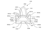
- FIG. 2 is a cross-sectional view taken along the line II-II in FIG.
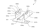
- FIG. 3 is a perspective view of the fixture in FIG.
- the light source unit 100 will be described.
- the light source unit 100 includes, for example, a tubular housing 101, a first end 102 that is one end of the housing 101, and a second end that is the other end of the housing 101. And an end portion 103. Further, the light source unit 100 houses a light source substrate 221 in which a light emitting element 222 serving as a light source such as an LED is provided. Then, the light source unit 100 is held by, for example, three attachments 150, and is fixed to the attachment target W by the attachments 150.
- the mounting target W is, for example, lighting used for ceilings, signboards, showcases, and the like. The details of the first end portion 102 and the second end portion 103 will be described later in connection with the connection of the two light source units 100.
- the housing 101 has, for example, a flat portion 201, a first protruding portion 202, and second protruding portions 203a and 203b.
- the flat portion 201, the first protruding portion 202, and the second protruding portions 203a and 203b each extend in the longitudinal direction of the housing 101.
- the outer shape of the housing 101 can also be regarded as the outer shape of the light source unit 100.
- the flat portion 201 has, for example, a flat surface on the outer peripheral surface side of the housing 101. Further, for example, a groove 208 extending in the longitudinal direction is provided on the flat surface of the flat portion 201.
- the first protruding portion 202 has a cross section protruding in a direction intersecting the direction along the flat portion 201. Further, the first protruding portion 202 gradually expands from the top thereof toward the lower part of FIG. Furthermore, inside the first protruding portion 202, for example, a light source substrate 221 is provided so as to extend in the longitudinal direction of the housing 101.
- the light source substrate 221 is provided with, for example, a plurality of light emitting elements 222 arranged in the longitudinal direction of the light source substrate 221.
- the light emitting element 222 is provided so as to face the first protruding portion 202.
- first protruding portion 202 for example, substrate supporting portions 221a and 221b that support the light source substrate 221 are provided so as to extend in the longitudinal direction.
- the 221a and 221b are, for example, recesses, and the edge of the light source substrate 221 is detachably inserted to fix the light source substrate 221 in the first protruding portion 202.
- the first protruding portion 202 transmits the light from the light emitting element 222 to the outside. As a result, the light source unit 100 functions as lighting.
- the second protrusions 203a and 203b for example, have a cross section as viewed in the longitudinal direction that protrudes from the first protrusion 202 on both sides in the direction along the flat portion 201 (the left-right direction in FIG. 2). More specifically, the second protrusions 203a and 203b are flat with the inclined surfaces 231a and 231b that extend and incline from the lower part of the first protrusion 202 in the direction along the flat portion 201 (left-right direction in FIG. 2). It has side surface portions 232a and 232b that stand up from both ends of the portion 201.
- the fixture 150 is, for example, a member on which the light source unit 100 is mounted and mounted on the mounting target W. As shown in FIG. 1, for example, the three attachments 150 are attached to the light source unit 100 on the first end 102 side, the second end 103 side, and the central portion.
- the mounting position and number of the mounting tools 150 are not limited to this.
- the fixture 150 is formed, for example, by punching, bending, or the like from a plate-shaped metal.
- the fixture 150 has a flat plate portion 251, an upright portion 252a / 252b, a bent portion 253a / 253b, a holding portion 254a / 254b, and a connecting portion 356a / 356b.
- the flat plate portion 251 contacts the flat portion 201 of the light source unit 100 and supports the light source unit 100 when the light source unit 100 is mounted, for example. Then, when the flat plate portion 251 is attached to the attachment target W, the flat plate portion 251 comes into contact with the attachment target W.
- the flat plate portion 251 has a protrusion portion 258 that protrudes on the surface side on which the light source unit 100 is mounted.
- the protruding portion 258 is provided so as to extend in the longitudinal direction of the flat plate portion 251.
- the longitudinal direction of the light source unit 100 and the longitudinal direction of the attachment 150 (flat plate portion 251) are substantially parallel when the light source unit 100 is attached to the attachment 150, and are the same in the present embodiment. This will be described as a direction.
- the protrusion 258 is fitted into the groove 208 of the flat portion 201 of the light source unit 100 when the light source unit 100 is attached to the fixture 150, and supports the light source unit 100.
- the flat plate portion 251 contacts the flat portion 201 to support the light source unit 100.
- the upright portions 252a and 252b are opposed to each other, for example, and are upright from both ends of the flat plate portion 251. More specifically, the upright portions 252a and 252b are upright from both ends of the flat plate portion 251 in a direction orthogonal to the longitudinal direction.
- the standing portions 252a and 252b are, for example, flat plates.
- the upright portions 252a and 252b contact the second protruding portions 203a and 203b of the light source unit 100 and support the light source unit 100 when the light source unit 100 is mounted on the fixture 150. More specifically, the standing portions 252a and 252b contact the side surface portions 232a and 232b of the second protrusions 203a and 203b, and support the light source unit 100. That is, the distance between the standing portions 252a and 252b is substantially equal to the distance between the side surface portions 232a and 232b of the light source unit 100 (width in the direction orthogonal to the longitudinal direction of the flat portion 201).
- the bent portions 253a and 253b are bent from the tip of the upright portions 252a and 252b upright from the flat plate portion 251 toward the space between the upright portions 252a and 252b. Further, the bent portions 253a and 253b are elastically deformable.
- the bent portions 253a and 253b are provided with openings 355a and 355b. By providing the openings 355a and 355b, the elastic force of the bent portions 253a and 253b is adjusted, and for example, the bent portions 253a and 253b can be elastically deformed.
- the openings 355a and 355b are not provided, and the bent portions 253a and 253b are made thinner than the flat plate portion 251 and the standing portions 252a and 252b, and a plurality of slits and the like are provided in the bent portions 253a and 253b. By doing so, the elastic force of the bent portions 253a and 253b can be adjusted similarly to the openings 355a and 355b.
- the fixture 150 when the fixture 150 is manufactured from a plate-shaped member such as a metal plate by punching and bending, the bent portions 253a and 253b are formed with the same thickness in other portions, so that the light source unit 100 is used. When mounted, the rigidity may be too high and elastic deformation may be difficult. On the other hand, by providing the bent portions 253a and 253b with openings or the like as described above, the elastic force is adjusted, and the light source unit 100 is easily attached to the fixture 150.
- the holding portions 254a and 254b extend from the bent portions 253a and 253b below the space sandwiched between the standing portions 252a and 252b. More specifically, the holding portions 254a and 254b are flat plates extending from the bent portions 253a and 253b, and are inclined with respect to the standing portions 252a and 252b.
- the holding portions 254a and 254b contact the second protruding portions 203a and 203b of the light source unit 100 when the light source unit 100 is mounted on the fixture 150, and support the light source unit 100. More specifically, the light source unit 100 is supported by the tips of the holding portions 254a and 254b coming into contact with the inclined surfaces 231a and 231b of the second protruding portions 203a and 203b of the light source unit 100. Furthermore, when the light source unit 100 is attached to the holders 254a and 254b when the light source unit 100 is to be removed, for example, when the light source unit 100 is to be removed upward in FIG. In this case, it is possible to prevent the tip ends of the holding portions 254a and 254b from being caught by the second protruding portions 203a and 203b and the light source unit 100 from being easily removed.
- the connecting portions 356a and 356b extend in a direction orthogonal to the longitudinal direction of the flat plate portion 251 for example. Further, the connecting portions 356a and 356b are provided diagonally with respect to the flat plate portion 251.
- the connection portions 356a and 356b are provided with connection holes 357a and 357b. Then, the attachment 150 is attached to the attachment target W through the connection holes 357a and 357b, for example, with screws or the like.
- the configuration for attaching the attachment 150 to the attachment target W is not limited to this.
- the attachment 150 may be attached to the attachment target W via a connection hole provided in the flat plate portion 251.
- the flat portion 201 of the light source unit 100 comes into contact with the flat plate portion 251 of the fixture 150, and the second protrusions 203a and 203b
- the holder 150 is held by coming into contact with the holding portions 254a and 254b of the holder 150. More specifically, in the light source unit 100, the protrusion 258 of the flat plate portion 251 is fitted into the groove 208 of the flat portion 201 and comes into contact with the light source unit 100, and the holding portion 254a is attached to the inclined surfaces 231a and 231b of the second protrusions 203a and 203b. -The tip of 254b is brought into contact with the fixture 150 to be held by the fixture 150.
- the second protrusions 203a and 203b contact the upright portions 252a and 252b, so that the light source unit 100 is more stably held by the fixture 150. More specifically, the light source unit 100 is more stably held by the fixture 150 by the side surface portions 232a and 232b of the second protruding portions 203a and 203b coming into contact with the facing surfaces of the standing portions 252a and 252b. .. In particular, by making the side surface portions 232a and 232b flat, the light source unit 100 is held by the fixture 150 more stably than the flat standing portions 252a and 252b.
- the distance from the flat plate portion 251 to the bent portions 253a and 253b and the distance from the flat plate portion 251 to the light source substrate 221 when the light source unit 100 is attached to the fixture 150 are made substantially the same, or the flat plate portion. It is preferable to make the distance from 251 to the light source substrate 221 larger than the distance from the flat plate portion 251 to the bent portions 253a and 253b. Accordingly, it is possible to prevent the light from the light emitting element 222 in the light source unit 100 held by the fixture 150 from being blocked by the fixture 150.
- one of the second protrusions 203b of the light source unit 100 is inserted between the holders 254a and 254b of the fixture 150.
- the other second projecting portion 203a of the light source unit 100 is pushed downward into the space between the standing portions 252a and 252b.
- the bent portions 253a and 253b are pushed by the light source unit 100 and elastically deformed, and the holding portions 254a and 254b are pushed toward the rising portions 252a and 252b.
- the light source unit 100 is further pushed into the space between the upright portions 252a and 252b.
- the holding portions 254a and 254b pushed by the light source unit 100 return to their original shapes due to the elastic force of the bent portions 253a and 253b, and the light source unit 100 returns to the fixture 150. It is installed.
- the tips of the holding portions 254a and 254b move along the inclined surfaces 231a and 231b of the second protruding portions 203a and 203b. Therefore, the contact between the holding portions 254a and 254b and the second protruding portions 203a and 203b can be maintained.
- a flat-blade screwdriver is inserted between the first protruding portion 202 and the holding portion 254b shown in FIG. 4C, and the second protruding portion 203b is inserted. Push it down. As a result, the second protrusion 203b is lowered into the gap 401 between the flat portion 201 and the flat plate portion 251, using the protrusion 258 as a fulcrum, and the holding of the light source unit 100 by the holding portion 254b is released. At this time, the second protruding portion 203a rises upward with the protruding portion 258 as a fulcrum.
- a minus driver is further pushed into the gap 401 along the standing portion 252b, and the tip of the minus driver is hooked on the lower portion of the second protruding portion 203b and pushed upward.
- the protrusion 258 serves as a fulcrum, and the second protrusion 203a is lowered downward, and at the same time, the second protrusion 203b is raised.
- the second protruding portion 203b is pushed up above the holding portion 254b, and the light source unit 100 can be removed from the fixture 150.
- the light source unit 100 can be easily removed from the fixture 150 by particularly providing the protrusion 258. Further, since the openings 355a and 355b are provided and the elastic force of the bent portions 253a and 253b is adjusted as described above, the holding portions 254a and 254b can be elastically deformed more easily, and the light source units by the holding portions 254a and 254b can be easily deformed. The holding of 100 can be released. Even if the protrusion 258 is not provided, the light source unit 100 can be removed by inserting a flat-blade screwdriver or the like into the lower portion of the second protrusion 203b in the same manner.
- FIG. 5 is a diagram showing an example of a state in which two light source units 100A and 100B are connected.
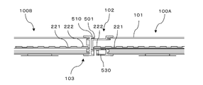
- FIG. 6 is a sectional view taken along line VI-VI in FIG.
- the light source unit 100A and the light source unit 100B have the same configuration, and these may be collectively referred to as the light source unit 100. Wiring is omitted in FIG.
- the light source unit 100 has, for example, a first end portion 102 and a second end portion 103 as shown in FIGS. 1, 5, and 6.
- the first end 102 has, for example, a first connecting portion 501 and a wiring 520.
- the second end 103 has, for example, a second connecting 510.
- the first connecting portion 501 is, for example, a convex portion protruding in the longitudinal direction of the housing 101 from the end portion of the housing 101.
- the second connecting portion 510 is, for example, a recess that fits into the first connecting portion 501 so as to extend from the end portion of the housing 101 in the longitudinal direction of the housing 101.
- the two light source units 100A and 100B are connected by fitting the first connecting portion 501 and the second connecting portion 510. It should be noted that the first connecting portion 501 and the second connecting portion 510 are not limited to the above-mentioned configuration, and may be any configuration that can be connected.
- a light source substrate 221 provided with a light emitting element 222 is arranged inside the first connecting portion 501.
- the light source substrate 221 provided with the light emitting element 222 is, for example, a part of the light source substrate 221 provided with the light emitting element 222 provided inside the housing 101.
- the light source substrate 221 extends to the vicinity of the end of the housing 101.
- the distance between the light emitting element 222 closest to the light source unit 100B in the light source unit 100A and the light emitting element 222 closest to the light source unit 100A in the light source unit 100B is a predetermined value.
- This predetermined value is, for example, a distance at which the joint between the first connecting portion 501 and the second connecting portion 502 does not become dark when the light source units 100A and 100B are connected to emit light.
- the light source substrate 221 for example, it is preferable to arrange a plurality of light emitting elements 222 along the longitudinal direction of the light source substrate 221 and arrange the adjacent light emitting elements 222 at substantially equidistant distances. This allows the light source unit 100A to emit light with uniform brightness over the longitudinal direction. Then, for example, by setting the predetermined value to be substantially the same as the distance between the adjacent light emitting elements 222, the joint between the first connecting portion 501 and the second connecting portion 502 can be made of the other portion of the light source unit. You can get closer to the brightness. Accordingly, the joint between the first connecting portion 502 and the second connecting portion 510 can be made inconspicuous.
- the distance between the light emitting element 222 closest to the light source unit 100B in the light source unit 100A and the light emitting element 222 closest to the light source unit 100A in the light source unit 100B is set between the adjacent light emitting elements 222 provided on the light source substrate 221.
- the brightness between the light source units 100A and 100B can be made the same as that of other parts, so that there is no more seam. It can emit light.
- the light emitting elements 222 provided in each of the light source units 100A and 100B be arranged in a line.
- the light source units 100A and 100B can be made to emit light more integrally.
- the wiring 520 is for supplying electric power to the light emitting element 222 provided on the light source substrate 221 for example. Then, for example, a connector connected to a power source is provided at the tip of the wiring 520. As shown in FIG. 5, for example, the wiring 520 is a portion in which the first connecting portion 501 and the second connecting portion 510 are connected at the first end portion 102 of the connected light source units 100A and 100B, that is, the first It is drawn out from a portion other than the portion of the connecting portion 501 that contacts the second connecting portion 510, or is drawn out from the end surface of the housing 101 from which the first connecting portion 501 projects.
- the wiring 520 is drawn out from the housing 101 side, for example, more than the portion of the first connecting portion 501 that contacts the second connecting portion 510. More specifically, the wiring 520 is drawn out via, for example, a lead-out portion 530.
- the lead-out portion 530 is provided, for example, in a portion of the first connecting portion 501 other than the portion connected to the second connecting portion 510, or in the end portion of the housing 101. Accordingly, the wiring 520 does not interfere with light emission when the light source units 100A and 100B are connected, and the light source units 100A and 100B can emit light seamlessly.
- the lead-out portion 530 is provided, for example, on the side opposite to the surface of the light source substrate 221 on which the light emitting element 222 is provided. As a result, the wiring 520 is pulled out in the direction opposite to the direction in which the light of the light emitting element 222 is irradiated, and it is possible to prevent the wiring 520 from blocking the light of the light emitting element 222.
- the light source units can be connected. Further, since the light source substrate provided with the light emitting element extends to the first connecting portion of the light source unit, that is, the light emitting element provided on the light source substrate is also arranged in the first connecting portion, the connected light source units are joined together. Can be emitted without light.
- the present invention is not limited to the above-described embodiment, and is substantially the same configuration as the configuration shown in the above-described embodiment, a configuration having the same action and effect, or a configuration capable of achieving the same object. May be replaced with.
Landscapes
- Engineering & Computer Science (AREA)
- General Engineering & Computer Science (AREA)
- Arrangement Of Elements, Cooling, Sealing, Or The Like Of Lighting Devices (AREA)
- Non-Portable Lighting Devices Or Systems Thereof (AREA)
- Fastening Of Light Sources Or Lamp Holders (AREA)
Abstract
連結して継ぎ目なく発光させることができる光源ユニットを提供する。光源ユニットは、発光素子が設けられた光源基板と、前記光源基板を収納する管状のハウジングと、前記ハウジングの端部から突出し、他の光源ユニットと連結可能な第1連結部と、を有し、前記第1連結部の内部に前記発光素子が設けられている。
Description
本発明は、光源ユニットに関する。本願は、2019年3月1日に、日本に出願された特願2019-37279号に基づく優先権を主張するものであり、その内容をここに援用する。
例えば、特許文献1には、断面形状が三角形である光源ユニットが開示されている。
しかしながら、特許文献1に開示された光源ユニットは、光源ユニットの端部から引き出されている構成が開示されているのみである。そのため、例えば2つの光源ユニットを連結しようとした場合、配線が邪魔となって、継ぎ目なく、いわゆるシームレスに照明を配置することが困難であった。本発明の一形態は、連結して継ぎ目なく発光させることができる光源ユニットを提供することにある。
本発明の一形態の光源ユニットは、発光素子が設けられた光源基板と、前記光源基板を収納する管状のハウジングと、前記ハウジングの端部から突出し、他の光源ユニットと連結可能な第1連結部と、を有し、前記第1連結部の内部に前記発光素子が設けられている。
以下、本発明の実施形態について、図面を参照しつつ説明する。なお、図面については、同一又は同等の要素には同一の符号を付し、重複する説明は省略する。
(第1の実施形態)
図1は、本実施形態に係る光源ユニットを、取付具を介して取り付け対象Wに取り付けた状態の一例を示す図である。図2は、図1におけるII-II矢視断面図である。図3は、図1における取付具の斜視図である。
図1は、本実施形態に係る光源ユニットを、取付具を介して取り付け対象Wに取り付けた状態の一例を示す図である。図2は、図1におけるII-II矢視断面図である。図3は、図1における取付具の斜視図である。
まず、光源ユニット100について説明する。
図1、図2に示すように、光源ユニット100は、例えば、管状のハウジング101と、ハウジング101の一方の端部である第1端部102と、ハウジング101の他方の端部である第2端部103とを有する。また、光源ユニット100は、内部にLED等の光源となる発光素子222が設けられた光源基板221を収納している。そして、光源ユニット100は、例えば、3つの取付具150により保持され、取付具150により取り付け対象Wに固定される。この取り付け対象Wは、例えば、天井、看板、ショーケース等に用いられる照明等である。なお、第1端部102および第2端部103の詳細については、2つの光源ユニット100の連結についての説明にて後述する。
ハウジング101は、例えば、平坦部201と、第1突出部202と、第2突出部203a・203bと、を有する。平坦部201、第1突出部202、第2突出部203a・203bは、それぞれ、ハウジング101の長手方向に伸びている。なお、ハウジング101の外形は、光源ユニット100の外形ともみなすことができる。
平坦部201は、例えば、ハウジング101の外周面側が平坦面となっている。さらに、平坦部201の平坦面には、例えば、長手方向に伸びる溝208が設けられている。
第1突出部202は、例えば、図2に示すように、断面が、平坦部201に沿う方向と交差する方向に突出している。また、第1突出部202は、その頂部から図2の下方に向かって、徐々に広がるようになっている。さらに、第1突出部202の内部には、例えば、光源基板221が、ハウジング101の長手方向に伸びるように設けられている。光源基板221には、例えば、複数の発光素子222が光源基板221の長手方向に並ぶように設けられている。発光素子222は、第1突出部202に面するように設けられている。さらに、第1突出部202の内周面には、例えば、光源基板221を支持する基板支持部221a・221bが長手方向に伸びるように設けられている。この221a・221bは、例えば凹部となっており、光源基板221の端縁が着脱可能に挿入され、光源基板221を第1突出部202内に固定する。第1突出部202は、発光素子222からの光を外部に透過する。これにより、光源ユニット100は、照明として機能する。
第2突出部203a・203bは、例えば、長手方向から見た断面が、第1突出部202から平坦部201に沿う方向の両側(図2の左右方向)に突出する。より具体的には、第2突出部203a・203bは、第1突出部202の下部から更に平坦部201に沿う方向(図2の左右方向)に広がって傾斜する傾斜面231a・231bと、平坦部201の両端部から起立した側面部232a・232bと、を有する。
次いで、取付具150について、図1、図2、図3に基づいて説明する。
取付具150は、例えば、光源ユニット100が装着され、取り付け対象Wに取り付けるための部材である。取付具150は、例えば、図1に示すように、光源ユニット100の第1端部102側、第2端部103側、中央部の3つ取り付けられる。なお、この取付具150の取付位置および数は、これに限定されるものではない。取付具150は、例えば、板状の金属から打ち抜き、曲げ加工等により形成される。
取付具150は、平板部251と、起立部252a・252bと、屈曲部253a・253bと、保持部254a・254bと、接続部356a・356bと、を有する。
平板部251は、例えば、光源ユニット100が装着された際に、光源ユニット100の平坦部201と当接して、光源ユニット100を支持する。そして、平板部251は、取り付け対象Wに取り付けられた際に、取り付け対象Wと接触する。
また、平板部251は、光源ユニット100が装着される面側に突起する突起部258を有する。この突起部258は、平板部251の長手方向に伸びるように設けられている。なお、光源ユニット100の長手方向と、取付具150(平板部251)の長手方向とは、光源ユニット100を取付具150に装着した際に略平行となるものであり、本実施形態においては同方向として説明する。
そして、この突起部258は、光源ユニット100が取付具150に装着された際に、光源ユニット100における平坦部201の溝208と嵌め込まれ、光源ユニット100を支持する。なお、突起部258を設けない場合には、平板部251が平坦部201と当接することにより、光源ユニット100を支持する。
起立部252a・252bは、例えば、互いに対向し、平板部251の両端部から起立している。より具体的には、起立部252a・252bは、平板部251における長手方向と直交する方向の両端部から起立している。この起立部252a・252bは、例えば平板状である。
そして、起立部252a・252bは、光源ユニット100が取付具150に装着された際に、光源ユニット100の第2突出部203a・203bと当接し、光源ユニット100を支持する。より具体的には、起立部252a・252bは、第2突出部203a・203bの側面部232a・232bに当接し、光源ユニット100を支持する。つまり、起立部252a・252b間の距離は、光源ユニット100の側面部232a・232b間(平坦部201の長手方向と直交する方向の幅)と略等しくなっている。
屈曲部253a・253bは、起立部252a・252bの平板部251から起立した先端から両起立部252a・252bで挟まれた空間側に屈曲している。また、屈曲部253a・253bは、弾性変形可能となっている。また、この屈曲部253a・253bには、開口部355a・355bが設けられている。この開口部355a・355bを設けることにより、屈曲部253a・253bの弾性力が調整され、例えば、屈曲部253a・253bを弾性変形させることができる。また、この開口部355a・355bを設けず、この屈曲部253a・253bを、平板部251や起立部252a・252b等よりも肉薄にしたり、屈曲部253a・253bに複数のスリット等を設けたりすることによっても開口部355a・355bと同様に屈曲部253a・253bの弾性力を調整することができる。
特に、取付具150を、金属板等の板状部材から、打ち抜き加工および曲げ加工により製造した場合、屈曲部253a・253bは、その他の部分を同じ厚さで形成されるため、光源ユニット100を装着する際に剛性が高すぎて弾性変形しにくい場合がある。それに対して、上記のように屈曲部253a・253bに開口部等を設けることにより、弾性力が調整され、光源ユニット100を取付具150に装着しやすくなる。
保持部254a・254bは、屈曲部253a・253bから、両起立部252a・252bで挟まれた空間の下方に伸びている。より具体的には、保持部254a・254bは、屈曲部253a・253bから伸びる平板状であり、起立部252a・252bに対して傾斜している。
そして、保持部254a・254bは、光源ユニット100が取付具150に装着された際に、光源ユニット100の第2突出部203a・203bと当接し、光源ユニット100を支持する。より具体的には、保持部254a・254bの先端部が光源ユニット100の第2突出部203a・203bにおける傾斜面231a・231bと当接することにより、光源ユニット100を支持する。さらに、この保持部254a・254bは、光源ユニット100が取付具150に装着された状態で、光源ユニット100を取り外そうとした場合、例えば、図2において光源ユニット100を上方に取り外そうとした場合、保持部254a・254bの先端が第2突出部203a・203bに引っ掛かり光源ユニット100が容易に取り外されることを防止することができる。
接続部356a・356bは、例えば、平板部251の長手方向と直交する方向に伸びている。また、接続部356a・356bは互いに平板部251に対して対角線上に設けられる。この接続部356a・356bには、接続孔357a・357bが設けられている。そして、取付具150は、接続孔357a・357bを介して、例えばねじ等により取り付け対象Wに取り付けられる。なお、取付具150を取り付け対象Wに取り付ける構成はこれに限定されるものではなく、例えば、平板部251に設けた接続孔を介して取り付け対象Wに取り付けてもよい。
ここで、光源ユニット100が取付具150に装着された状態についてさらに説明する。
光源ユニット100が取付具150に装着された状態では、光源ユニット100は、図2に示すように、少なくとも平坦部201が取付具150の平板部251に当接し、第2突出部203a・203bが取付具150の保持部254a・254bに当接することにより、取付具150に保持される。より具体的には、光源ユニット100は、平坦部201の溝208に平板部251の突起部258が嵌め込められて当接し、第2突出部203a・203bの傾斜面231a・231bに保持部254a・254bの先端部が当接することにより、取付具150に保持される。
さらに、光源ユニット100は、第2突出部203a・203bが起立部252a・252bと当接することより、より安定して取付具150に保持される。より具体的には、光源ユニット100は、第2突出部203a・203bの側面部232a・232bが起立部252a・252bの対向面に当接することにより、より安定して取付具150に保持される。特に側面部232a・232bを平面状にすることにより、平板状の起立部252a・252bとより安定して光源ユニット100は取付具150に保持される。
さらに、平板部251から屈曲部253a・253bまでの距離と、光源ユニット100を取付具150に装着した際の平板部251から光源基板221までの距離とを略同一とするか、または、平板部251から光源基板221までの距離を平板部251から屈曲部253a・253bまでの距離よりも大きくすることが好ましい。これにより、取付具150に保持された光源ユニット100における発光素子222からの光が、取付具150により遮られることを防止することができる。
続いて、光源ユニット100を取付具150に装着する例、および光源ユニット100を取付具150から取り外す場合の例について説明する。
まず、図4(a)に示すように、光源ユニット100における一方の第2突出部203bを、取付具150の保持部254a・254bとの間に挿入する。
次いで、図4(b)に示すように、光源ユニット100におけるもう一方の第2突出部203aを下方に起立部252a・252b間の空間に押し込んでいく。これにより、屈曲部253a・253bが光源ユニット100に押されて弾性変形し、保持部254a・254bが起立部252a・252bの方に押される。
そして、光源ユニット100をさらに起立部252a・252b間の空間に押し込む。これにより、図4(c)に示すように、光源ユニット100に押されていた保持部254a・254bが屈曲部253a・253bの弾性力により元の形状に戻り、光源ユニット100が取付具150に装着される。なお、このとき、屈曲部253a・253bが弾性力により元の形状に戻る際には、保持部254a・254bの先端が、第2突出部203a・203bの傾斜面231a・231bに沿って移動するため、保持部254a・254bと第2突出部203a・203bとの当接を維持することができる。
また、光源ユニット100を取付具150から取り外す際には、例えば、マイナスドライバーを、図4(c)に示す、第1突出部202と保持部254bとの間に差し込み、第2突出部203bを下方に押し込む。これにより、突起部258が支点となって、平坦部201と、平板部251との間の隙間401に第2突出部203bが下がり、保持部254bによる光源ユニット100の保持が解除される。このとき、第2突出部203aは、突起部258が支点となって上方に上がる。
次に、さらにマイナスドライバーを、例えば起立部252bに沿って隙間401に押し込み、マイナスドライバーの先端を第2突出部203bの下部に引っかけて上方に押し上げる。これにより、突起部258が支点となって、第2突出部203aが下方に下がり、同時に第2突出部203bが上がる。そして、第2突出部203bが保持部254bよりも上方に押し上げられ、光源ユニット100を取付具150から取り外すことができる。
このように、特に突起部258を設けることにより、光源ユニット100を取付具150から取り外しやすくすることができる。また、上記のように開口部355a・355bを設け、屈曲部253a・253bの弾性力が調整されているため、より容易に保持部254a・254bを弾性変形させ、保持部254a・254bによる光源ユニット100の保持を解除することができる。なお、突起部258を設けていなくても、同様に例えばマイナスドライバー等を第2突出部203bの下部に差し込むことより、光源ユニット100を取り外すことができる。
次いで、光源ユニット100A・100Bを連結する場合について説明する。図5は、2つの光源ユニット100A・100Bを連結した状態の一例を示す図である。図6は、図5におけるVI-VI矢視断面図である。なお、本実施形態においては光源ユニット100Aと光源ユニット100Bとを同様の構成とし、これらを合わせて光源ユニット100とも記載することがある。また、図6では配線を省略している。
光源ユニット100は、図1、図5、図6に示すように、例えば、第1端部102と、第2端部103とを有する。
第1端部102は、例えば、第1連結部501と、配線520と、を有する。
第2端部103は、例えば、第2連結部510を有する。
第1連結部501は、例えば、ハウジング101の端部から、ハウジング101の長手方向に突出した凸部となっている。第2連結部510は、例えば、ハウジング101の端部から、ハウジング101の長手方向に伸びるように、第1連結部501と嵌合する凹部となっている。この第1連結部501と第2連結部510とが嵌合することにより、2つの光源ユニット100A・100Bが連結される。なお、第1連結部501と第2連結部510とは、上記の構成に限定されず、連結できる構成であればよい。
また、第1連結部501の内部には、例えば、図6に示すように、発光素子222が設けられた光源基板221が配置されている。この発光素子222が設けられた光源基板221は、例えば、ハウジング101の内部に設けられた発光素子222が設けられた光源基板221の一部である。一方、第2端部103においては、ハウジング101の端部の近傍まで光源基板221が伸びている。これにより、第1連結部501と第2連結部510とが連結された際には、第1連結部501に配置された光源基板221と、第2端部103の近傍まで伸びた光源基板221とが近接して配置される。そのため、連結された2つの光源ユニット100A・100Bを継ぎ目がないように発光させることができる。なお、第1連結部501および第2連結部502は、例えば、発光素子222からの光を透過する材料で形成されている。
また、光源ユニット100A・100Bを連結した際に、光源ユニット100Aにおいて光源ユニット100Bに最も近接する発光素子222と、光源ユニット100Bにおいて光源ユニット100Aに最も近接する発光素子222との距離は、所定値以下であることが好ましい。この所定値は、例えば、光源ユニット100A・100Bを連結して、発光させた場合に、第1連結部501と第2連結部502の継ぎ目が、暗くならない程度の距離である。
さらに、光源基板221においては、例えば、複数の発光素子222を光源基板221の長手方向に沿うように配列し、隣り合う発光素子222の距離を略等距離に配置すること好ましい。これにより、光源ユニット100Aを長手方向にわたって均一な明るさで発光させることができる。そして、例えば、上記所定値を、上記隣り合う発光素子222間の距離と、略同一に設定することにより、第1連結部501と第2連結部502の継ぎ目を、光源ユニットの他の部分の明るさに近づけることができる。これにより、第1連結部502と第2連結部510との継ぎ目を目立たなくすることができる。特に、光源ユニット100Aにおいて光源ユニット100Bに最も近接する発光素子222と、光源ユニット100Bにおいて光源ユニット100Aに最も近接する発光素子222との距離を、光源基板221に設けた隣り合う発光素子222間の距離と略同一とすることにより、発光ユニット100A・100Bを連結した際に、発光ユニット100A・100B間の明るさが他の部分と同様の明るさにすることができ、より継ぎ目がないように発光させることができる。
さらにまた、光源ユニット100A・100Bを連結した際に、光源ユニット100A・100Bの各々に設けられた発光素子222が一列に並ぶように構成することが好ましい。これにより、光源ユニット100A・100Bをより一体的に発光させることができる。
配線520は、例えば、光源基板221に設けられた発光素子222に電力を供給するためのものである。そして、例えば、配線520の先端には電源に接続されるコネクターが設けられている。配線520は、例えば、図5に示すように、連結された光源ユニット100A・100Bにおける第1端部102において、第1連結部501と第2連結部510とが連結された部分、つまり第1連結部501の第2連結部510との接触する部分以外から引き出されているか、または、第1連結部501が突出するハウジング101の端面から引き出されている。言い換えれば、配線520は、例えば、第1連結部501の第2連結部510と接触する部分よりも、ハウジング101の側から引き出されている。より具体的には、配線520は、例えば、引き出し部530を介して引き出される。この引き出し部530は、例えば、第1連結部501の第2連結部510と連結される部分以外の部分、またはハウジング101の端部に設けられる。これにより、配線520は、光源ユニット100A・100Bを連結した際に、発光の邪魔にならず、継ぎ目なく光源ユニット100A・100Bを発光させることができる。また、この引き出し部530は、例えば、光源基板221の発光素子222が設けられた面とは反対側に設けられることが好ましい。これにより、発光素子222の光の照射される方向とは逆方向に配線520が引き出されることになり、配線520が発光素子222の光を妨げることを防止することができる。
本実施形態の光源ユニットによれば、光源ユニットの端面から配線を引き出していないため、光源ユニットを連結することができる。さらに、光源ユニットの第1連結部まで、発光素子が設けられた光源基板が伸びている、つまり第1連結部にも光源基板に設けた発光素子が配置されるため、連結した光源ユニットを継ぎ目なく発光させることができる。
本発明は、上記実施の形態に限定されるものではなく、上記実施の形態で示した構成と実質的に同一の構成、同一の作用効果を奏する構成又は同一の目的を達成することができる構成で置き換えてもよい。
Claims (6)
- 発光素子が設けられた光源基板と、
前記光源基板を収納する管状のハウジングと、
前記ハウジングの端部から突出し、他の光源ユニットと連結可能な第1連結部と、を有し
前記配線は、前記第1連結部の前記他の光源ユニットと連結される部分以外、または前記第1連結部が設けられた前記ハウジングの端部から引き出されている、
前記第1連結部の内部に前記発光素子が設けられている光源ユニット。 - 前記発光素子に電力を供給する配線が、前記第1連結部の前記他の光源ユニットと連結される部分以外、または前記第1連結部が設けられた前記ハウジングの端部から引き出されている、請求項1に記載の光源ユニット。
- 前記ハウジングにおける前記第1連結部とは反対側の端部に設けられ、前記他の光源ユニットと連結可能な第2連結部を有する、請求項1または2に記載の光源ユニット。
- 前記発光素子は前記光源基板が伸びる方向に沿って複数配列され、
前記他の光源ユニットと連結された際に、前記発光素子における前記他の光源ユニットに最も近接する前記発光素子と、前記他の光源ユニットにおける前記光源ユニットに最も近接する前記発光素子との距離が、所定値以下である、請求項1~3のいずれか1項に記載の光源ユニット。 - 前記光源基板において隣り合う前記発光素子の距離は、略等距離であり、
前記発光素子における前記他の光源ユニットに最も近接する前記発光素子と、前記他の光源ユニットにおける前記光源ユニットに最も近接する前記発光素子との距離が、前記光源基板において隣り合う前記発光素子間の距離と略同一である、請求項1~3のいずれか1項に記載の光源ユニット。 - 前記他の光源ユニットと連結された際に、前記発光素子は、前記他の光源ユニットの設けられた前記発光素子と一列に並ぶ、請求項1~5のいずれか1項に記載の光源ユニット。
Priority Applications (1)
| Application Number | Priority Date | Filing Date | Title |
|---|---|---|---|
| JP2021503989A JP7312242B2 (ja) | 2019-03-01 | 2020-02-26 | 光源ユニット |
Applications Claiming Priority (2)
| Application Number | Priority Date | Filing Date | Title |
|---|---|---|---|
| JP2019-037279 | 2019-03-01 | ||
| JP2019037279 | 2019-03-01 |
Publications (1)
| Publication Number | Publication Date |
|---|---|
| WO2020179552A1 true WO2020179552A1 (ja) | 2020-09-10 |
Family
ID=72338004
Family Applications (1)
| Application Number | Title | Priority Date | Filing Date |
|---|---|---|---|
| PCT/JP2020/007555 Ceased WO2020179552A1 (ja) | 2019-03-01 | 2020-02-26 | 光源ユニット |
Country Status (2)
| Country | Link |
|---|---|
| JP (1) | JP7312242B2 (ja) |
| WO (1) | WO2020179552A1 (ja) |
Citations (2)
| Publication number | Priority date | Publication date | Assignee | Title |
|---|---|---|---|---|
| JP2011086420A (ja) * | 2009-10-14 | 2011-04-28 | H2o co ltd | 導光体と構造体を一体化させたled照明灯 |
| JP2012064391A (ja) * | 2010-09-15 | 2012-03-29 | Panasonic Corp | 照明器具 |
-
2020
- 2020-02-26 WO PCT/JP2020/007555 patent/WO2020179552A1/ja not_active Ceased
- 2020-02-26 JP JP2021503989A patent/JP7312242B2/ja active Active
Patent Citations (2)
| Publication number | Priority date | Publication date | Assignee | Title |
|---|---|---|---|---|
| JP2011086420A (ja) * | 2009-10-14 | 2011-04-28 | H2o co ltd | 導光体と構造体を一体化させたled照明灯 |
| JP2012064391A (ja) * | 2010-09-15 | 2012-03-29 | Panasonic Corp | 照明器具 |
Also Published As
| Publication number | Publication date |
|---|---|
| JPWO2020179552A1 (ja) | 2020-09-10 |
| JP7312242B2 (ja) | 2023-07-20 |
Similar Documents
| Publication | Publication Date | Title |
|---|---|---|
| EP2642189B1 (en) | Vehicular lamp | |
| JP4582087B2 (ja) | 発光ダイオードの固定構造 | |
| KR101333809B1 (ko) | Led 소켓 조립체 | |
| JP5801116B2 (ja) | コネクタ及びコネクタを備えるモジュール | |
| JP2014053267A (ja) | Led直管形ランプ及び照明装置 | |
| JP2011187315A (ja) | Led照明器具 | |
| JP2012230864A (ja) | ソケット対及びそのソケット対を備えた照明器具 | |
| JP7312242B2 (ja) | 光源ユニット | |
| JP2005209812A (ja) | 発光素子ユニット | |
| JP7316348B2 (ja) | 光源ユニットの取付具、および光源ユニット | |
| JP5830404B2 (ja) | 車両用灯具 | |
| JP4345016B2 (ja) | 発光装置 | |
| JP7251271B2 (ja) | 照明装置 | |
| JP5756906B2 (ja) | 照明器具 | |
| JP2019106257A (ja) | 照明器具 | |
| JP5662788B2 (ja) | 照明器具 | |
| EP2813747A1 (en) | Straight tube lamp and luminaire | |
| WO2016175101A1 (ja) | 照明装置 | |
| JP6384783B2 (ja) | 照明器具 | |
| JP2020140925A (ja) | 照明装置 | |
| JP2011040188A (ja) | 車両用灯具 | |
| JP7243393B2 (ja) | 照明装置 | |
| JP6699118B2 (ja) | 照明器具 | |
| JP2017183125A (ja) | 光源ユニットおよび照明器具 | |
| JP6570407B2 (ja) | 照明装置 |
Legal Events
| Date | Code | Title | Description |
|---|---|---|---|
| 121 | Ep: the epo has been informed by wipo that ep was designated in this application |
Ref document number: 20765598 Country of ref document: EP Kind code of ref document: A1 |
|
| ENP | Entry into the national phase |
Ref document number: 2021503989 Country of ref document: JP Kind code of ref document: A |
|
| NENP | Non-entry into the national phase |
Ref country code: DE |
|
| 122 | Ep: pct application non-entry in european phase |
Ref document number: 20765598 Country of ref document: EP Kind code of ref document: A1 |