WO2020175444A1 - メタノール合成システム及びその方法 - Google Patents
メタノール合成システム及びその方法 Download PDFInfo
- Publication number
- WO2020175444A1 WO2020175444A1 PCT/JP2020/007378 JP2020007378W WO2020175444A1 WO 2020175444 A1 WO2020175444 A1 WO 2020175444A1 JP 2020007378 W JP2020007378 W JP 2020007378W WO 2020175444 A1 WO2020175444 A1 WO 2020175444A1
- Authority
- WO
- WIPO (PCT)
- Prior art keywords
- oxygen carrier
- reactor
- reaction
- hydrogen
- rei
- Prior art date
- Legal status (The legal status is an assumption and is not a legal conclusion. Google has not performed a legal analysis and makes no representation as to the accuracy of the status listed.)
- Ceased
Links
Classifications
-
- C—CHEMISTRY; METALLURGY
- C01—INORGANIC CHEMISTRY
- C01B—NON-METALLIC ELEMENTS; COMPOUNDS THEREOF; METALLOIDS OR COMPOUNDS THEREOF NOT COVERED BY SUBCLASS C01C
- C01B3/00—Hydrogen; Gaseous mixtures containing hydrogen; Separation of hydrogen from mixtures containing it; Purification of hydrogen; Reversible storage of hydrogen
- C01B3/02—Production of hydrogen; Production of gaseous mixtures containing hydrogen
- C01B3/22—Production of hydrogen; Production of gaseous mixtures containing hydrogen by decomposition of gaseous or liquid organic compounds
- C01B3/24—Production of hydrogen; Production of gaseous mixtures containing hydrogen by decomposition of gaseous or liquid organic compounds of hydrocarbons
-
- C—CHEMISTRY; METALLURGY
- C01—INORGANIC CHEMISTRY
- C01F—COMPOUNDS OF THE METALS BERYLLIUM, MAGNESIUM, ALUMINIUM, CALCIUM, STRONTIUM, BARIUM, RADIUM, THORIUM, OR OF THE RARE-EARTH METALS
- C01F17/00—Compounds of rare earth metals
-
- C—CHEMISTRY; METALLURGY
- C07—ORGANIC CHEMISTRY
- C07C—ACYCLIC OR CARBOCYCLIC COMPOUNDS
- C07C29/00—Preparation of compounds having hydroxy or O-metal groups bound to a carbon atom not belonging to a six-membered aromatic ring
- C07C29/15—Preparation of compounds having hydroxy or O-metal groups bound to a carbon atom not belonging to a six-membered aromatic ring by reduction of oxides of carbon exclusively
- C07C29/151—Preparation of compounds having hydroxy or O-metal groups bound to a carbon atom not belonging to a six-membered aromatic ring by reduction of oxides of carbon exclusively with hydrogen or hydrogen-containing gases
-
- C—CHEMISTRY; METALLURGY
- C07—ORGANIC CHEMISTRY
- C07C—ACYCLIC OR CARBOCYCLIC COMPOUNDS
- C07C31/00—Saturated compounds having hydroxy or O-metal groups bound to acyclic carbon atoms
- C07C31/02—Monohydroxylic acyclic alcohols
- C07C31/04—Methanol
-
- Y—GENERAL TAGGING OF NEW TECHNOLOGICAL DEVELOPMENTS; GENERAL TAGGING OF CROSS-SECTIONAL TECHNOLOGIES SPANNING OVER SEVERAL SECTIONS OF THE IPC; TECHNICAL SUBJECTS COVERED BY FORMER USPC CROSS-REFERENCE ART COLLECTIONS [XRACs] AND DIGESTS
- Y02—TECHNOLOGIES OR APPLICATIONS FOR MITIGATION OR ADAPTATION AGAINST CLIMATE CHANGE
- Y02P—CLIMATE CHANGE MITIGATION TECHNOLOGIES IN THE PRODUCTION OR PROCESSING OF GOODS
- Y02P20/00—Technologies relating to chemical industry
- Y02P20/10—Process efficiency
- Y02P20/129—Energy recovery, e.g. by cogeneration, H2recovery or pressure recovery turbines
Definitions
- the present invention relates to a methanol synthesis system and a method thereof.
- Methanol synthesis has a production amount comparable to that of ethylene, which is 1.21 million and propylene, which is 0.881:1. Reforming methane to synthesize hundred and! - 1 2, from the syngas, are methanol synthesis (2 7 0 ° ⁇ ⁇ 3 0 0 ° ⁇ ).
- the methane reforming reaction is an endothermic reaction, which requires a reaction in a high temperature field, and methane combustion and hydrogen by-product combustion are performed to supply the heat. For this reason, it has become a accompanied process a large hundred 2 emissions.
- a reforming reaction technique is known as a method for producing hydrogen from a hydrocarbon-based material.
- the reforming reaction technique is steam reforming, dry reformate Min grayed using hundred 2, partial oxidation and the like with air-oxygen.
- the ratio of ⁇ and hydrogen must be 1: 2 or more, Steam reforming is required.
- Non-Patent Document 1 Low-temperature waste heat of less than 500 ° ⁇ is released to the outside of the chemical process system with almost no use, and by proposing a technology for utilizing low-temperature waste heat, energy conservation and 3_Rei there is ⁇ want room to reduce 2 emissions.
- the total amount of low-temperature waste heat of less than 500 ° ⁇ in Japan is estimated to be 1,018 betajuules (") per year. This corresponds to about 10% of the total energy consumed in Japan (see Non-Patent Document 1). Loss of low-temperature waste heat is a common problem not only in Japan but around the world.
- Non-Patent Document 1 The Energy conserveat i on Center, Japan, https ://www. as i ae ec-co L. eccj .or. j p/ (accessed 26 December 26, 2018)
- the membrane reactor is not suitable for large-scale treatment of hydrocarbon materials, and it is desirable to solve the problem by another approach.
- the present invention has been made in view of the above problems, and an object thereof is to perform steam reforming of a hydrocarbon-based material at low temperature by utilizing low-temperature waste heat of less than 700 ° C. To do.
- the present inventors have found that a reaction that produces hydrogen and carbon oxides from a hydrocarbon-based material and a reaction that produces hydrogen from water. It was found that the above object can be achieved by individually executing the above, and the present invention has been completed. Specifically, the present invention provides the following. ⁇ 0 2020/175 444 4 (: 170? 2020 /007378
- the invention according to the first feature comprises a hydrogen and synthesis gas production system, and a methanol synthesis system for synthesizing methanol using at least a part of the hydrogen and the synthesis gas as raw materials.
- the gas production system includes a first reactor that reacts an oxygenated oxygen carrier with a hydrocarbon-based material to generate hydrogen and carbon oxides, and a reduced oxygen carrier and water with each other.
- a hydrogen co-producing methanol synthesizer which has a second reactor for producing oxidized oxygen carrier and hydrogen, and the oxygen carrier circulates and flows between the first reactor and the second reactor. To do.
- an oxidation reaction of a hydrocarbon-based material and a reduction reaction of an oxygen carrier occur in the first reactor.
- the lattice oxygen of the oxygen carrier is used for the oxidation reaction of the hydrocarbon-based material, and the oxidation reaction produces hydrogen and carbon oxides. Since no water is used as a raw material in the first reactor, all substances that can be produced when a hydrocarbon material and water are reacted in a single reactor 1 to 1 2 ⁇ , ⁇ ⁇ , ⁇ ⁇ 2 , 1 to 1 2 ) do not exist in the same reaction field. Thus, all materials in the same reaction field constraints (0 ⁇ ⁇ 1-1 2 ⁇ , hundred, hundred 2, 1-1 2) caused by the presence reaction equilibrium can be avoided.
- the oxygen component contained in water oxidizes the oxygen carrier, whereby hydrogen is produced.
- the reaction in the second reactor depending on the type of oxygen carrier material (determined by the magnitude of the redox potential of the oxidation agent), for example in the case of using a Rei_6_rei 2,
- the oxidized oxygen carrier which is an exothermic reaction and one of the reaction products in the second reactor, can recover the heat capacity generated by the exothermic reaction.
- the oxygen carrier circulates and flows from the second reactor to the first reactor, and the oxygen carrier that has absorbed the waste heat in the first reactor is brought into contact with the hydrocarbon-based material so that the hydrocarbon-based material is The heat required for the endothermic reaction with is supplied. External waste heat from other processes can also be used. That is, in the invention according to the first feature, the oxygen carrier can function not only as a transport source of oxygen but also as a transport source of heat. ⁇ 0 2020/175 444 5 (: 170? 2020 /007378
- the invention according to the second feature comprises: a hydrogen and synthesis gas production system; and a methanol synthesis system for synthesizing methanol using at least a part of the hydrogen and the synthesis gas as raw materials.
- the gas production system includes a plurality of reactors filled with an oxygen carrier, the plurality of reactors are configured to be able to introduce a hydrocarbon-based material or water, and among the plurality of reactors, It is possible to introduce the hydrocarbon-based material into the reactor in which the oxygen carrier is in an oxidized state and oxidize the hydrocarbon-based material.
- a methanol synthesizing apparatus capable of switching a material to be introduced between the hydrocarbon-based material and the water.
- the invention according to the third feature provides an apparatus wherein the reaction temperature in the invention according to the first or the second feature is 600°C or less.
- low temperature waste heat of 600°C or less is used as a hydrocarbon material. ⁇ 0 2020/175 444 6 ⁇ (: 170? 2020 /007378
- cerium oxide (Rei_6_rei 2), chromium-doped cerium oxide ( ⁇ "one Rei_6 ⁇ 2 ), Iron oxide-zirconia-based composite oxide ( 6 ⁇ Father 2 “ ⁇ 2 ), Iron oxide (6 2 ⁇ 3 ), Indium oxide ( ⁇ n 2 ⁇ 3 ), Yttrium-stabilized zirconium oxide (3) ), scandium oxide-doped zirconium oxide (3 0 3 7), scandium oxide ( 3 0 2 0 3 ), lanthanum gallium oxide (!_
- the oxygen carrier is a specific material
- the low temperature waste heat generated by the known exothermic reaction such as methanol synthesis or ammonia synthesis can be used for the reforming reaction of hydrocarbon material to hydrogen. , ⁇ it wants to reduce energy saving and hundred 2 emissions.
- the invention according to a fifth feature is the invention according to any one of the first to fourth features, wherein the oxygen carrier and the metal cocatalyst coexist inside the reactor. ⁇ 0 2020/175 444 7 ⁇ (: 170? 2020 /007378
- the reforming reaction of the hydrocarbon-based material can be more efficiently advanced by the action of the metal promoter.
- the invention according to a sixth feature provides a device in which the average primary particle diameter of the oxygen carrier in the invention according to any one of the first to third features is 1 or less.
- the exposed surface area (contact possibility) with the hydrocarbon-based material that is the reactant in the first reactor and with the water that is the reactant in the second reactor is to become large, increasing efficiency for the oxygen carrier oxygen transfer, for advanced reforming reaction to hydrogen from hydrocarbon material even at low temperatures, as a result, energy saving - ⁇ wants to reduce and hundred 2 emissions.
- the invention according to a seventh feature provides a system in which the oxygen carrier in the invention according to any one of the first to sixth features has a shape having the most active exposed surface.
- the shape of the oxygen carrier is a substantially octahedral and / or substantially cubic body, oxygen carriers, a (1 1 1) plane and / or (1 0 0) plane It has as the main exposed surface.
- the (100) plane of the oxygen carrier is unstable and has a greater oxygen mobility (oxygen storage/release capacity). Therefore, according to the engagement Ru invention ninth feature, since the advanced reforming reaction to hydrogen from hydrocarbon material even at low temperatures, as a result, ⁇ it wants to reduce energy saving and ⁇ 3_Rei 2 emissions.
- the invention according to the eighth feature corresponds to a category difference from the invention according to the first feature.
- the invention according to the ninth feature corresponds to a category difference from the invention according to the second feature. According to the inventions according to the eighth and ninth features, it is possible to process a large amount of reforming of a hydrocarbon material into hydrogen in a short time by utilizing a low temperature waste heat of 700 ° C. is there. ⁇ 0 2020/175444 8 ⁇ (: 170? 2020/007378 Effect of invention
- Fig. 1 is a configuration example of a hydrogen and synthetic gas manufacturing system 1 in the methanol synthesizing apparatus according to the present embodiment.
- FIG. 2 is a diagram showing the relationship between the oxygen storage/release capacity (0 30) of oxygen carriers and the oxygen release rate constant.
- FIG trioctahedral is Kino ⁇ 3_Rei-hundred 2 emission map and was methane reforming reaction 9 0 0 ° ⁇ using system 1.
- FIG 3 Snake is Kino ⁇ 3_Rei-hundred 2 emission map and was methane reforming reaction 6 0 0 ° ⁇ using the system 1.
- FIG 3_Rei is Kino ⁇ 3_Rei-hundred 2 emission map and was methane reforming reaction 4 0 0 ° ⁇ using the system 1.
- [30] 3 0 is Kino ⁇ 3_Rei-hundred 2 emission map and was methane reforming reaction 3 0 0 ° ⁇ using the system 1.
- FIG. 4 eight shows a relationship between the Been methane reforming reaction Kino reaction temperature conversion and ⁇ 3_Rei 2 emissions using a system according to the prior art.
- 4 Snake shows the relationship between the reaction temperature and the conversion and (3 0 2 emissions when subjected to methane reforming reaction using the hydrogen production system 1 according to this embodiment shaped condition.
- FIG. 5 is a diameter of 1 0 and height 3 0_Rei the scale of the reactor at 1 5 0 0 1: - ⁇ 1-1 4 / day for feasible methane reforming This is the result of simulating the relationship between the oxygen carrier particle IV! (0) and the oxygen release rate constant.
- Fig. 6 shows the flow of each compound and energy in each reactor in the hydrogen production system 1.
- Fig. 7 shows the equivalence ratio in the reforming reaction from methane to methanol.
- Fig. 8 is an example of a conventional methane reforming process.
- FIG. 9 is in the synthesis of chromium-doped cerium oxide ( ⁇ "one Rei_6_rei 2) ⁇ 0 2020/175 444 9 ⁇ (: 170? 2020 /007378
- FIG. 2 is a schematic diagram of a synthesizing apparatus 30 used.
- FIG. 10 is a diagram showing the results of evaluation of oxygen storage/release capacity ( ⁇ ) in the low temperature range in Test Example 2-1.
- Fig. 11 is a diagram showing the relationship between the atomic column of cerium element and the oxygen vacancy forming property in particles in Test Example 2-2.
- Fig. 12 shows an image of the cerium element DET IV! in Test Example 2-2.
- FIG. 13 is a diagram showing a rate of expansion of voids of cerium element in Test Example 2-2.
- Fig. 14 shows the relationship between the ratio of lattice expansion in cerium nanoparticles and the energy required to form oxygen vacancies between cerium atoms in Test Example 2-2. Is.
- Figure 1 5 is a test example 2 - In 3 is a diagram showing the results of the feeder and subjected to Metan oxygen carrier response experiments in a batch reactor when the oxygen carrier is a ⁇ 6_Rei 2 Nanokyu Bed ..
- Figure 1 6 is Test Example 2 - In 3, the oxygen carrier is an iron oxide Jirukoni A-based composite oxide methane (6 ⁇ father one " ⁇ 2) batch reactor at a - oxygen carrier reaction It is a figure which shows the result at the time of experimenting.
- Fig. 17 shows the result of simulating the industrial scale of the chemical loop manufacturing system 1 shown in Fig. 1.
- the methanol synthesis apparatus includes a hydrogen and synthesis gas production system, and a methanol synthesis system that synthesizes methanol using at least a part of the hydrogen and the synthesis gas obtained from the production system as raw materials.
- the hydrogen and synthesis gas production system in the present embodiment includes a first reactor and a second reactor.
- the system may be a chemical loop type system in which an oxygen carrier circulates and flows between the first reactor and the second reactor, or a cyclic operation system in which gases are alternately switched to perform switching. Good.
- the form of the system is not particularly limited, and may be a two-column circulation type fluidized bed or a form in which the stationary phase reactor is operated by switching. Among them, it is preferable that the system form is a two-column circulation type fluidized bed, since reforming of hydrocarbon material to hydrogen can be performed in a larger amount.
- Figure 1 shows an example of the configuration of system 1 when system 1 is a two-column circulation type fluidized bed catalytic reactor.
- the system 1 comprises a first reactor 10 and a second reactor 20.
- the first reactor 10 has a first inlet 11 and a first outlet 12.
- the hydrocarbon material is supplied from the first inlet 11. Then, as the hydrocarbon-based material moves from the first inlet 11 toward the first outlet 12, the hydrocarbon-based material and the oxidized oxygen carrier IV! inside the first reactor 10 ( ⁇ ) reacts with each other to generate reduced oxygen carrier IV! (), hydrogen and carbon oxide. Then, hydrogen and carbon oxides are discharged from the first outlet 12. On the other hand, the reduced oxygen carrier IV! () circulates and flows toward the second inlet 21 of the second reactor 20.
- IV! ( ⁇ ) represents an oxidized oxygen carrier
- IV! () represents a reduced oxygen carrier
- an oxidation reaction of the hydrocarbon-based material and a reduction reaction of the oxygen carrier occur in the first reactor 10.
- the lattice oxygen of the oxygen carrier is used for the oxidation reaction of the hydrocarbon-based material, and the oxidation reaction produces hydrogen and carbon oxides.
- water is not used as a raw material in the first reactor 10, all substances (0 ⁇ 1 ⁇ 1 2 0) that can be produced when a hydrocarbon material and water are reacted in a single reactor. , hundred, hundred 2, 1-1 2) will not be present in the same reaction field.
- all materials in the same reaction field (0 ⁇ 1-1 2 ⁇ , O O, 00 2, 1 and 1 2) can be avoided constraints caused by the reaction equilibrium that exists.
- an oxygen carrier redox cycle is used.
- the oxygen carrier is preferably a solid electrolyte so that the redox cycle can be realized at less than 700 ° .
- the solid electrolyte is preferably a material finely divided into nanoparticles, and in the long-periodic periodic table, the boron of the group ⁇ ⁇ ⁇ ⁇ 1 ⁇ V ⁇ group silicon (3 I) — Arsenic of Group V (8 3) _ Tellurium of Group I
- An example is an element on the line with the line as the boundary, and an element on the left side or below the boundary in the long period type periodic table.
- the elements of the V group of V group are ⁇ , ⁇ , 1 ⁇ 1 [3 ⁇ 4 Rei_1, ⁇ 3, I ", 1: etc., the I Snake Group element in ⁇ Li, eight 9, Hachiri etc., Chapter II Snake group elements ⁇ , etc.
- oxygen carrier cerium oxide (Rei_6_rei 2), chromium-doped oxidation of cerium ( ⁇ "one Rei_6_rei 2), iron oxide-zirconia based composite oxide (6 ⁇ Father Iron oxide (6 2 ⁇ 3), indium oxide ( ⁇ 2 ⁇ 3), said tri-um-stabilized zirconium oxide ( ⁇ 3), scandium oxide doped oxide Gilles Koniumu (3_Rei 3), scandium oxide (3_Rei 2 ⁇ 3 ), Lanthanum oxide ⁇ 0 2020/175 444 12 (: 170? 2020 /007378
- the low temperature waste heat generated by known exothermic reactions such as methanol synthesis or ammonia synthesis can be used as a heat source from the outside to the first reactor 10. and ( ⁇ want to reduce 3_Rei 2 emissions.
- the oxygen carrier cerium oxide (Rei_6_rei 2), chromium-doped oxide cell potassium ( ⁇ "one Rei_6_rei 2), iron oxide-zirconia based composite oxide (6 ⁇ father one" ⁇ 2), lanthanum It is preferable to contain at least one selected from the group consisting of strontium manganite (I-31 ⁇ / ⁇ ) and lanthanum threontium cobalt ferrate (!_30).
- oxygen carriers may be used alone or in combination of two or more.
- the oxygen carrier and the metal cocatalyst coexist inside the first reactor 10, or that the oxygen carrier carry the metal cocatalyst.
- the reaction in the first reactor 1 0, as reforming reaction of hydrocarbon-based materials, in addition to the production of 1 to 1 2 is the reaction product, 1 1 to 1 2 is further oxidized to 1 2 A reaction that produces ⁇ also occurs.
- the presence of metal promoter, from 1 to 1 2 can be released to the metal, to prevent oxidation from 1 to 1 2 to! - 1 2 ⁇ , as possible out to increase from 1 to 1 2 recovery amount.
- the kind of the metal co-catalyst is not particularly limited, and transition metals, noble metals and alloys thereof can be exemplified. Specifically, 1 ⁇ 1 ⁇ ⁇ , [3 ⁇ 4, 9 ⁇ , 6 ⁇ 0,
- the oxygen storage/release capacity of the oxygen carrier (030 means the number of moles of oxygen contained in the oxygen carrier of unit mass.
- the value of ⁇ of the oxygen carrier is not particularly limited. In order to shorten the reaction time in the first reactor 10 and the second reactor 20 without increasing the size of the first reactor 10 and the second reactor 20, the oxygen storage/release capacity ( ⁇ 30 is preferably as large as possible.
- the reaction temperature in the first reactor 10 is 0. 30. 0. 2 0 1 0 1 1/1 ⁇ 9 (200 1110 1/9) or higher. It is preferable that it is ⁇ 3 ⁇ 1 ⁇ ⁇ /1 ⁇ 9 (300 1110 1/9) or more, and it is ⁇ 4 ⁇ 1 ⁇ 1/1 ⁇ 9 (400 ⁇ 1/) or more. It is even more preferable, and it is particularly preferable that it is 0.51 ⁇ 10 1/1 ⁇ 9 (500° 1/) or more.
- !_ 31 ⁇ / ⁇ is ⁇ 30 at 350° ⁇ ! .1 5 0 1 1/1 ⁇ 9 (1, 150 0 I/9).
- the lanthanum strontium cono-noretoferrite (!_30) at 350°° is ⁇ 783 ⁇ 1 ⁇ 1/1 ⁇ 9 (783 ⁇ ! ⁇ ⁇ /9).
- Oxygen carrier 03(3) is measured by the following method 1 or method 2.
- the oxygen release rate constant corresponds to the time that the oxygen carrier stays inside the first reactor 10.
- the lower limit of the oxygen release rate constant is not particularly limited, but in order to realize the shortening of the reaction time in the first reactor 10, the oxygen release rate constant is ⁇ 0.02 ⁇ n- l (reaction time : 50 minutes or less), ⁇ .03 ⁇ 1 ⁇ n- l or more (reaction time: 33 minutes or less), more preferably ⁇ .04 ⁇ 1 ⁇ n- l or more (reaction time: 25 minutes or less) is more preferable, and 0.05 min n- l or more (reaction time: 20 minutes or less) is more preferable, and 0.1 min. It is particularly preferable that it is I 1 -1 or more (reaction time: 10 minutes or less).
- the oxygen release rate constant is not particularly limited, the oxygen release rate constant is not more than 0.25 25! I n - 1 (reaction time) in order to surely advance the reaction in the first reactor 10. : 4 minutes or more) is preferable, and ⁇ . It is more preferably n- l or less (reaction time: 5 minutes or more).
- the product of 03 (3 and the oxygen release rate constant is an effective indicator of the reaction efficiency in the first reactor, and the unit is 111 ⁇ I It is 1 ⁇ 4.
- the value of this product is not particularly limited, but when considering the above-mentioned large-scale synthesis of methanol as an example, the value of 0.04 1 0 1 0 1 If it is above, ⁇ ⁇ is ⁇ .
- the size of the first reactor 10 is 700 ° in a normal size reactor having a diameter of 10 and a height of 30 .
- Fig. 2 is a diagram showing the relationship between 03 (3 and the oxygen release rate constant, where the horizontal axis (X axis) is the oxygen release rate constant and the vertical axis (V axis) is 03 (3).
- the release rate constant By setting the conditions so that it falls within the area surrounded by 25 (white area in Fig. 2), the low temperature waste heat of less than 700 ° C can be used without increasing the size of the first reactor. A large amount of methane reforming reaction can be realized in a shorter time.
- the upper limit of the average primary particle size of the oxygen carrier is not particularly limited, but it should be 1 or less from the viewpoint of maximizing the exposed surface area (contactability) with the reactant and the ease of forming oxygen vacancies due to lattice strain. Is preferable, more preferably 100 nm or less, and 50 n It is more preferable that it is not more than 30 nm, and it is further preferable that it is not more than 30 nm. It is particularly preferable that
- the lower limit of the average primary particle diameter of the oxygen carrier is also not particularly limited.
- nano particles are made into secondary particles by compaction molding, and the secondary particles are used in a packed bed reactor for cyclic operation or as a circulating fluidized bed particle.
- the average primary particle diameter of the oxygen carrier is determined by capturing an image of the oxygen carrier particles with a Ding 1 ⁇ /1 (transmission electron microscope), and analyzing the Ding 1 ⁇ /1 image by image analysis. ⁇ It is assumed that the value is obtained by analyzing with image measurement software.
- the shape of the oxygen carrier has a greater oxygen mobility at low temperature (°30), it is necessary to expose the most active surface, which determines the particle shape. varies depending on the kind of the oxygen carrier material, it is the most unstable surface heat force histological its information can be easily obtained from your material data base over the scan, and the like.
- 0-shaped oxygen carrier in the case of 6_Rei 2 is substantially cubic, (1 0 0) is preferably the surface and major exposed surfaces. for 6 3 ⁇ 4, preferably in the (1 1 0) plane of the major exposed surface.
- 0 6_Rei second nanoparticle catalyst may be in the form of octahedral or cubic. Also, ⁇ 0 2020/175 444 17 ⁇ (: 170? 2020/007378
- 0 6_Rei 2 nanoparticles catalysts have a (1 1 1) plane, 1 1 0 surface and / or (1 0 0) plane major exposed surface.
- metal oxide nanoparticles having an active surface exposed at 30% or more of the particle surface are preferable.
- the active surface is the most stable surface energetically, a Rei_6_rei in 2 (1 0 0) plane. This allows oxygen transfer at low temperatures.
- ⁇ percentage is exposed (1 0 0) plane in the surface of the 6_Rei 2 nanoparticles, 3 0%, more preferably at least 50%, 7 0% or more is not more preferable .
- the ratio that is exposed (1 0 0) plane in the surface of the ⁇ 6_Rei 2 nanoparticles are measured by Chomi IV!.
- the Rei_6_rei 2 nanoparticles preferably a this transition element is doped.
- ⁇ 60 2 Examples of transition elements doped into nanoparticles include ⁇ ”, ⁇ , “, etc. Among them, ⁇ ”, Is preferred.
- the doping amount of the transition elements in ⁇ 6_Rei 2 nanoparticles is based on the total weight of Rei_6_rei 2, ⁇ . 1 ⁇ ⁇ % or more is preferable, ⁇ ⁇ % or more is more preferable, 100 ⁇ ⁇ % or more is still more preferable, 150 ⁇ 10 ⁇ % or more is still more preferable,
- vacancies formed on the reduced ceria surface cause a reaction with water molecules and combine with oxygen to form the tetradecavalent state 0 6.
- the released hydrogen molecules are transferred to a decomposition compound to cause a hydrogenation reaction.
- the method for producing the oxygen carrier is not particularly limited, but when the oxygen carrier is metal oxide nanoparticles, for example, Patent No. 3 047 1 1 0 (one of the inventors of the patent is the present invention Can be manufactured by the method disclosed in (1).
- metal salts (genus metal, genus genus, metal genus, genus genus metal, genus metal
- Group I metal Group I metal, Group I metal, Group IV metal, Group IV metal, Group V metal,
- a metal salt of V metal, VI metal, VII metal, transition metal, etc. at a temperature of 200°C or higher at a subcritical or supercritical condition of water, and a pressure of 160°C.
- water is made into high-temperature and high-pressure water in a supercritical state or a subcritical state via a pressurizing means and a heating means, and before the fluid raw material is combined with this high-temperature and high-pressure water,
- a method for producing fine particles using high-temperature high-pressure water in which the high-temperature high-pressure water is cooled to a temperature lower than the critical temperature, and then the high-temperature high-pressure water and the fluid raw material are combined and mixed in a mixing section and then guided to a reactor.
- the metal oxide nanoparticles are produced by a method disclosed in, for example, Japanese Patent No. 39255936 (one of the inventors of the patent is the inventor of the present application). Can be collected afterwards.
- the surface of the nanoparticles is organically modified by binding to the surface of the nanoparticles through
- octahedra ⁇ 6_Rei 2 nanoparticles can be synthesized by a known method.
- Nanoparticles cube 0 6_Rei 2 (1) Preparation child a raw material solution in toluene, (2) an organic modifier using a cube 0 6 ⁇ 2 in supercritical water conditions synthesizing the nanoparticles, and (3) is synthesized by a method comprising removing the organic modifier without changing the cube 0 6 0 2 forms.
- the preparation of the nanoparticles of cubic ⁇ 6_Rei 2 can be performed as follows. This is a non-limiting example.
- a nanoparticle precursor solution of cubic cerium oxide is prepared. After that, the precursor solution is mixed with continuous stirring to obtain a clear solution. The precursor solution is mixed with deionized water and heated rapidly to 600-700 by using a furnace. Then the mixture is cooled. Cubic cerium oxide nanoparticles are obtained as a dispersion in a mixture of water, toluene and unreacted raw materials. Add ethanol to the nanoparticles in the toluene phase and centrifuge and decant. ⁇ 0 2020/175 444 20 (: 170? 2020 /007378
- the particles are dispersed in cyclohexan and then freeze dried under vacuum.
- the collected nanoparticles are calcined in air at temperatures as high as 300 ° C for several hours in order to remove any organic ligands from the surface of the particles.
- the calcined nanoparticle clarified by centrifugation and inclined ⁇ , then dried under reduced pressure, thereby obtaining nanoparticles cube 0 Yi_ ⁇ 2.
- the hydrocarbon-based material refers to a compound containing carbon and hydrogen in the molecule or a mixture thereof, and may contain other elements such as oxygen in the molecule.
- Examples of hydrocarbon-based materials include hydrocarbons, alcohols, ethers, biofuels and the like.
- the hydrocarbons are materials containing an alicyclic hydrocarbon, a cyclic or acyclic aliphatic hydrocarbon as a single component or a mixed component.
- Alicyclic hydrocarbons include, for example, cyclohexane, methylcyclohexane, dimethylcyclohexane, 1,3,5-trimethylcyclohexane and other monocyclic alicyclic compounds, decalin, methyldecalin, tetralin (tetrahydronaphthalene), methyltetralin. And the like, tricyclic alicyclic compounds such as tetradecahydroanthracene, and the like.
- Acyclic aliphatic hydrocarbons include Alkanes consisting of (methane, ethane, propane, butane, etc.) are included. Also, as hydrocarbons, natural gas,! _ ⁇ (liquefied petroleum gas), city gas, gasoline, naphtha, kerosene, diesel oil, etc. are also included.
- Examples of alcohols include methanol, ethanol, 2-propanol and the like.
- Examples of ethers include dimethyl ether and the like.
- Examples of biofuels include biogas, bioethanol, biodiesel, and biojet.
- the upper limit of the reaction temperature is not particularly limited, however, since the low temperature waste heat is used, the upper limit is preferably 600°C or less, more preferably 55°C or less. ⁇ 0 2020/175444 21 ⁇ (: 170? 2020 /007378
- the lower limit of the reaction temperature should be that the oxygen carrier has sufficient oxygen mobility (oxygen storage/release capacity), and from the viewpoint of effectively utilizing the low temperature waste heat, the lower the reaction temperature is, the lower the reaction temperature is. Is more preferable.
- Examples of the lower limit of the reaction temperature include room temperature or higher, 100°° or higher, 150°° or higher, 200°° or higher, 250°° or higher, and the like.
- the upper limit of the reaction time is not particularly limited, but in order to achieve further shortening, the reaction time is preferably 50 minutes or less, more preferably 33 minutes or less, and even 25 minutes. It is more preferably not more than 20 minutes, even more preferably not more than 20 minutes, particularly preferably not more than 10 minutes.
- the lower limit of the reaction time is not particularly limited, but the reaction time is preferably 4 minutes or more, and more preferably 5 minutes or more in order to surely proceed the reaction in the first reactor 10. More preferable.
- the material of the first reactor 10 is not particularly limited, and is not limited to a material having high temperature resistance such as chrome-molybdenum steel and stainless steel, and may be ordinary steel.
- the reaction from a hydrocarbon material to hydrogen requires a high temperature condition of 700 ° C or higher, and the material of the reactor is also a temperature resistant material such as chrome-molybdenum steel or stainless steel. It needs to be expensive.
- low temperature waste heat can be used, and ordinary steel having relatively small temperature resistance can also be used.
- a material having high temperature resistance imposes a large load on the environment when manufacturing the material.
- the greenhouse gas emissions in the life cycle of manufacturing chrome molybdenum steel and stainless steel are 2.42 and 4.3 5 ! ⁇ 9 _ ⁇ , respectively. ⁇ 2 equivalents / 1 ⁇ 9 _ steel (see Non-Patent Document 2).
- the greenhouse gas emissions in the life cycle of manufacturing ordinary steel are limited to 2.1 1 kg _ C ⁇ 2 equivalents/kg _ steel (see Non-Patent Document 2).
- the second reactor 20 has a second inlet 21 and a second outlet 22. Water is supplied from the second inlet 21. Then, as the water moves from the second inlet 21 toward the second outlet 22, the water reacts with the reduced oxygen carrier M () inside the second reactor 20 and is oxidized. It produces oxygen carrier M (0) and hydrogen. Then, hydrogen is discharged from the second outlet 22. On the other hand, the oxidized oxygen carrier M ( ⁇ ) circulates toward the first inlet 11 of the first reactor 10.
- M () represents a reduced oxygen carrier
- M (o) represents an oxidized oxygen carrier
- the hydrogen is discharged from the outlet of the second reactor 20, the system as a whole, cut with recovery and high purity hydrogen and a mixed gas of C_ ⁇ (C0 2) and H 2.
- a medium coexists, or that an oxygen carrier carry a metal promoter.
- metal promoter a 1 to 1 2 can be released to the metal, to prevent oxidation from 1 to 1 2 to 1 to 1 2 ⁇ , it can be increased 1-1 2 recovery amount.
- the oxygen component contained in water oxidizes the oxygen carrier, which produces hydrogen.
- the reaction in the second reactor 20 is an exothermic reaction, and the reaction suitably proceeds even at low temperature. Therefore, the reaction temperature in the second reactor 20 is not particularly limited.
- the reaction in the second reactor 20 is an exothermic reaction
- the oxidized oxygen carrier IV! ( ⁇ ) which is one of the reaction products in the second reactor 20 is It is possible to recover the waste heat generated by the exothermic reaction.
- Oxygen carrier IV! (0) circulates from second reactor 20 to first reactor 10 and absorbs waste heat in first reactor 10!
- the heat required for the endothermic reaction of the hydrocarbon-based material is supplied by bringing the hydrocarbon-based material into contact with the hydrocarbon-based material. That is, the system 1 described in the present embodiment can not only function the oxygen carrier as the oxygen transport source, but also function as the heat transport source. It is possible to suppress the amount of heat supplied to the container 10.
- the methanol synthesis system (not shown), which is one component of the methanol synthesis apparatus according to the present embodiment, synthesizes methanol using at least a part of hydrogen and synthesis gas obtained from the hydrogen and synthesis gas production system 1 as raw materials.
- System The configuration of this system is not particularly limited.
- Hexanoic acid decoration synthesized by supercritical method as oxidised oxygen carrier ⁇ 60 2 nanocube manufactured by Aitec Co., Ltd., 0831 ⁇ 1 ⁇ .1 306 -3 8-3, average primary particle size : 10 nm ⁇ 3 nm
- this nanocube is controlled by using an organic modifier (hexanoic acid in this example) so that the (100) plane becomes the main exposed surface. .. Therefore, the nano-cube was burned at 300° for 2 hours to remove the organic modifier from the nano-cube.
- Rei_6_rei 2 Rei_6_rei of 2 nanocubes was Rei_6_rei 2 Rei_6_rei of 2 nanocubes. It should be noted that the color of Rei_6_rei 2 nano cube was a yellow.
- Rei_ ⁇ _ ⁇ 2 is reacted with nanocube and methane was conducted the first reaction producing a carbon dioxide Rei_ ⁇ 2 ⁇ 3 nanocubes and hydrogen.
- the internal volume of the reactor was 5011_. Before the reaction, the 0. 19 0 62 0 2 nanocube was placed in a batch reactor under an atmosphere of 8 "in a glove box. After that, methane (purity: 99. 99995%, manufactured by Tanuma Oxygen Company) was introduced into the reactor at a pressure of 0.61 ⁇ /1 3. The reactor was placed in an electric furnace heated to the temperature shown in Table 1. After reacting for 10 to 60 minutes, the reactor was placed in a water bath. Upon cooling, a gas bag was used to collect the gas product through a valve fitted to the reactor.
- the gas product recovered in the gas bag was analyzed by a gas chromatograph equipped with a thermal conductivity detector (device name: 001-001 0000-201 4, packing material: 31 ⁇ 1 1 1 ⁇ 10 8 [3 ⁇ 4mi ⁇ 37 50/80) was used for analysis.
- the same batch reactor used in the first reaction was equipped with 0 6 2 0 3 nanocubes. Further loaded 63 Shino pure water (manufactured by Daiwa Pharmaceutical Co.), for easily recovering a gaseous product was entering guide to ⁇ . 31 ⁇ / 1 batch reactor 1 ⁇ 1 2 gas at third pressure .. The reaction was carried out at the temperatures listed in Table 1. After the reaction (5-60 minutes), the reactor was quenched and the gas product was collected and analyzed by the same method as in the first reaction.
- Figs. 3A to 3D show iso_C ⁇ 2 emission amount maps in Reference Example 1-1 and Examples 1-1 to 1-3.
- the numbers on the line in Figure 3 shows the percentage of C0 2 emissions when compared to conventional processes.
- the conventional process for comparison in this test example is the methane reforming process shown in FIG.
- the C_ ⁇ 2 emissions in conventional processes is 0. 432 kg -C_ ⁇ 2 equivalents / kg -CH 3 ⁇ H, this number was the following Non-Patent Document 3 as a reference.
- Non-Patent Document 3 A. Primas, Methanol, at plant, GLO, eco invent database version 2.0, eco invent report 8 (2007) 432-442.
- Figure 4 shows the relationship between the reaction temperature and the conversion and hundred 2 emissions in the first reaction.
- Fig. 4 shows the relationship in the conventional process, and
- Fig. 4 shows the relationship in the process according to this test example.
- reaction temperature exceeds 900 ° ⁇
- the reforming reaction of methane in the methane reforming process is almost saturated, and when the reaction temperature is higher than 900 ° ⁇ , it leads to heat loss. , the heat must be supplemented by the combustion of the fuel, leading to hundred 2 emissions.
- oxygen carrier particles IV! ( ⁇ ) are reduced by methane to form partially reduced oxygen carrier particles IV! (). Then, the partially reduced oxygen carrier particles IV! () are transported to the reactor in the second reaction. Then, in the reactor in the second reaction, as shown in equation (2), the reducible oxygen carrier particles IV! () Is oxidized by water vapor, oxygen carrier particles IV! (0) and? - 1 2 It is formed. Then, oxygen carrier particles IV! ( ⁇ ) are transported again to the reactor in the first reaction.
- an oxygen carrier particles IV! ( ⁇ ) is ⁇ 6_Rei 2, its physical properties, density 7.
- oxygen carrier particles IV! ( ⁇ ) are present inside the reactor in the first reaction. That is, the reaction time from the oxygen carrier particles IV! ( ⁇ ) to the reduced oxygen carrier particles IV! ( ⁇ ) is from the oxygen carrier particles IV! ( ⁇ ). ⁇ 02020/175444 28 ⁇ (: 170? 2020 /007378
- the rate constant of oxygen release by the oxygen carrier particles IV! ( ⁇ ) determines the amount of methane that can be treated in the first reaction.
- the reactivity index of oxygen carrier particles IV! (0) that is equal to (the amount of oxygen available for methane reforming in oxygen carrier particles IV! ( ⁇ ))
- X oxygen release rate constant: ⁇ 10 1 ⁇ 9 -1 111 ⁇ use.
- Figure 5 1 5001 at a diameter of 1 0 and a height 30 scale reactor: - ⁇ 1-1 4 / day methane reforming oxygen carrier particles for feasible IV (0 ) And the oxygen release rate constant of 03 (3).
- the oxygen release rate constant of oxygen carrier particles IV! If it is 1 ⁇ - 1 (the residence time inside the first reactor 10 of the oxygen carrier particle IV! (0) is 10 minutes), the oxygen carrier particle IV! ( ⁇ ) required ⁇ 3 ⁇ is ⁇ 4 1 ⁇ 1 ⁇ I- ⁇ (Dot point 8 in Fig. 5).
- 03_Rei oxygen carrier particles IV! (0) is not required necessarily 0.1 6 higher than the molar 9- 1.
- the oxygen release rate constant is on the horizontal axis (X axis), and 03 (3) of oxygen carrier particles IV! (0) is on the vertical axis (so axis).
- the oxygen carrier particle M ( ⁇ ) is It is suitable for using the chemical loop type hydrogen production system in this test example.
- Non-Patent Document 4 G. Guan, C. Fushimi, M. Ikeda, Y. Nakamura, A. Tsutsu mi, T. Suda, M. Ishizuka, H. Hatano, S. Matsuda, Y. Suzuki, F low beha viors in a high solid f lux circulating fluidized bed composed of ari ser, a downer and a bubbling fluidized bed, in: S. D Kim, J. Kang, J. K. Lee, YC Seo (Eds ⁇ ), Proceedings of the 13th International Conference on Fluidization-New Paradigm in Fluidization (Gyeong-ju, Korea)
- FIG. 6 shows the first reactor 10 and the second reactor when oxygen carrier particles M ( ⁇ ) having an oxygen carrier capacity of 0.23 mo I - ⁇ /kg -C e ⁇ 2 were used. The flow of each compound and energy at 20 is shown.
- FIG. 6(A) shows each compound and energy flow in the first reactor 10 and
- FIG. 6(B) shows each compound and energy flow in the second reactor 20.
- Ce_ ⁇ 2 valence state is modeled using a mixture of Ce_ ⁇ 2 and Ce 2 ⁇ 3, the amount of these materials corresponds to the valence state of cerium.
- a heat balance can be established by supplying heat to the first reactor 10 and cooling the second reactor 20.
- the sensible heat generated by the oxygen transfer of oxygen carrier particles M (0) can be used for the heat balance of the system. Therefore, it is possible to suppress the amount of external heat supplied from outside the system to the inside of the system by improving the ⁇ SC of the oxygen carrier particles M ( ⁇ ).
- Fig. 7 shows the equivalent ratio in the reforming reaction from methane to methanol.
- Comparative Example 1-1 is the equivalent ratio in the conventional process, that is, the methane reforming process shown in Fig. 8.
- Comparative Example 1 _ 1 is the current process, in which methane as a fuel is added to the raw material methane 1, and as products on the right side, methanol is produced at 0. 793 and C 0 2 # 0. 268. Does not produce hydrogen.
- the following reaction takes place.
- methane fuel is also used to generate combustion heat.
- Example 1-2 the methane reforming device in Fig. 8 is replaced with a chemical loop device. At that time, the reaction temperature was 400 ° ⁇ , and Comparative Example 1 —
- methanol can only be produced. Therefore, according to this embodiment, as compared with the conventional methanol production system, without using methane as a fuel for a low temperature, significantly reducing hundred 2 emissions, and can produce methanol at a high efficiency.
- Example 1-2 the amount of carbon dioxide produced can be suppressed as compared with Comparative Example 1-1, which can also contribute to environmental protection.
- the oxygen storage and release capacity ( ⁇ 30) was measured for each of 350° ⁇ , 400° ⁇ , 450° ⁇ and 500° ⁇ . The results are shown in Figure 10. It should be noted that 030 means the number of moles of oxygen contained in a unit mass of oxygen carrier.
- the oxygen carrier 030 is measured by the following method. ⁇ 02020/175444 32 ⁇ (: 170? 2020 /007378
- Reaction temperature that is, detection temperature (1 to 16 gas flows in the measurement system at 200° ⁇ , 250° ⁇ , 300° ⁇ , 350° ⁇ , 400° ⁇ , 450° ⁇ and 500° ⁇ ( This is the pretreatment.)
- Hexanoic acid modified by supercritical method as oxygen carrier ⁇ 60 2 nanocube manufactured by Aitec Co., Ltd., ⁇ 8 31 ⁇ 1 ⁇ .1 306 -38-3, average particle size: 10 nm ⁇ 3 nm
- this nanocube was controlled using an organic modifier (hexanoic acid in this example) so that the (100) plane becomes the main exposed surface. ing. Then, the nanocube was burned at 300° for 2 hours to remove the organic modifier from the nanocube.
- the organic modifier is removed (1 00) surface that Rei_ ⁇ _ ⁇ 2 nano cube was ⁇ 6 ⁇ 2 exposure.
- the oxygen carrier 0 0 3 was measured by the same method as in Example 2-1-1. The results are shown in Figure 10.
- Chromium-doped cerium oxide ( ⁇ "one Rei_6_rei 2) was synthesized by a flow-through supercritical hydrothermal synthesis method reported. 0 The apparatus 30 shown in Fig. 9 was used for the synthesis of 60 2 .
- the device 30 includes a raw material supply unit 31, a supercritical water supply unit 32, a mixing unit 33 for mixing the raw material and the supercritical water, and cooling the mixed liquid of the raw material and the supercritical water, And a cooling unit 34 which is contained in the container.
- the raw material supply section 31 has a raw material storage container 31 for storing the raw material, and a pump 3 1 pump for pumping the raw material stored in the raw material storage container 3 18 toward the mixing section 3 3. .. Pipes are connected between the raw material storage container 31 8 and the pump 3 1 9 and between the pump 3 1 1 and the mixing section 3 3, respectively.
- the supercritical water supply unit 32 includes a water container 32 for containing water and a water container.
- Have 0 and. Connect the water container 3 28 and the pump 3 2 9 with pipes, the pump 3 2 2 and the heating unit 3 2 (3, and the heating unit 3 2 (3 and the mixing unit 3 3 respectively. Has been done.
- temperature and pressure can be controlled.
- supercritical water preheated in the supercritical water supply unit 32 is supplied to the mixing unit 33 from another pipe different from the pipe provided in the raw material storage container 31.
- the temperature of the raw material was raised to the supercritical state.
- the raw material contains decanoic acid, which is an organic molecule
- both organic molecules and inorganic aqueous solution form a homogeneous phase in the supercritical state, and particle synthesis occurs there.
- rapid cooling was carried out by an external water cooling unit 348 provided in the cooling section 34, and the pressure was thereafter controlled by a back pressure valve (not shown).
- the reaction temperature in the mixing section 33 is 400° and the reaction pressure is The reaction time was less than 2 seconds.
- the container 34 containing the post-reaction liquid was cooled in a water bath at room temperature.
- 51 Hexane was used to extract the nanoparticle (hexane phase) from the decanoic acid modified product.
- 100 1 of ethanol as a poor solvent reagent was added to precipitate a precipitate from the hexane phase.
- centrifugation was carried out to obtain cubic crystals ⁇ “doped ⁇ ⁇ 2 nanoparticles.
- O 3 (3) of the oxygen carrier was measured by the same method as in Example 2 _ 1 _ 1 except that the oxygen carrier was the above-mentioned cubic ⁇ “doped 602 2 nanoparticles. Shown in.
- Example 2 - 1 - 4 Iron oxide-zirconia based composite oxide (6 ⁇ father one " ⁇ 2)
- Oxygen carrier 03 ⁇ was measured by the same method as in Example 2-1 1 except that the oxygen carrier was the iron oxide-zirconia-based composite oxide particles. The results are shown in Figure 10.
- Fig. 10 is a diagram showing the results of evaluation of the oxygen storage/release capacity ( ⁇ ) in the low temperature range of Test Example 2_1. Compared with 0 2 , exposed surface controlled cerium oxide (Example 2-1 -2) was higher, and ⁇ "doped cerium oxide (Example 2-1-3) was higher, and iron zirconia (Example 2-).
- 60 ⁇ 1 ” 2 is particularly excellent in 030, followed by chromium-doped cerium oxide ( ⁇ “_ 060 2 ), 060 2 nano It was confirmed that the cubes were superior in order.
- Oxygen mobility is related to the strain of the crystal lattice, Is doped, which causes lattice distortion and facilitates the formation of oxygen vacancies. This more chromium-doped, large oxygen mobility than 06_Rei 2 undoped is presumed reason obtained. ⁇ 0 2020/175 444 36 ⁇ (: 170? 2020 /007378
- Figure 11 shows that the average primary particle size from the top is 11 9 n, 8 n 01, 7 1 ⁇ 111, 6 1 ⁇ 111, 5 Column of cerium element when
- Figure 12 shows the image of the cerium element IV! in Test Example 2-2.
- Figure 12 shows the interatomic strain. The part that looks bright has a large distortion ⁇ 0 2020/175 444 37 ⁇ (: 170? 2020 /007378
- the image on the left is the image of cerium element IV with an average primary particle size of 11 11 and the image on the right shows an average primary particle size of 6
- the dots on the left and right images of the Tetsumi IV! represent cerium atoms, and the region surrounded by four cerium atoms is the region where oxygen can be incorporated into the molecule.
- (Min) in Fig. 12 is a visualization of the distortion between the cerium atoms by analyzing the image of Dinami 1 ⁇ /1 shown in (8) of Fig. 6.
- the color is gray (when the value is close to 0), the interatomic strain is small. The lighter the color is (the closer it is to white), the more the interatomic voids expand, indicating that oxygen is more easily incorporated into the voids. On the other hand, the darker the color (closer to black), the smaller the interatomic voids, indicating that it is difficult to incorporate oxygen into the voids.
- Fig. 13 shows the proportion of the lattice expansion of the cerium element from the left to the right in the image of Dingmi IV! shown in (8) of Fig. 12.
- (8) in Fig. 13 shows the state for the cerium element with an average primary particle size of 11 1 and (M) in Fig. 13 has an average primary particle size of 6 n. Is the state for the element cerium. From Fig. 13 also, it is confirmed that the smaller the average primary particle size of the oxygen carrier, the larger the lattice expansion between the atoms, and the easier the formation of oxygen vacancies due to lattice strain.
- Fig. 14 is a diagram showing the relationship between the rate at which lattice expansion is observed in cerium nanoparticles and the energy required to form oxygen vacancies between cerium atoms. According to Fig. 14, particles with a higher lattice expansion ratio ⁇ 02020/175444 38 ⁇ (: 170? 2020 /007378
- Oxygen carrier is cerium oxide ( ⁇ 3 6 ⁇ 2 ) [ ⁇ ⁇ 2 produced]
- Example 2 - 1 - cerium oxide used in 1 ( ⁇ 6 ⁇ 2) oxidation state was charged into a single reactor. Then, by introducing Rei_1 ⁇ 1 4, at 300 ° ⁇ oxidizes Rei_1 ⁇ 1 4, was measured the time course of the amount of carbon dioxide. At that time, the reaction pressure was 0.61 ⁇ /1 3. The results are shown in Figure 15 (8).
- Example 2 — 1 — 1 The cerium oxide used in Example 2 — 1 — 1 was brought to a reduced state and charged into one reactor. Then, water vapor was introduced to oxidize the reduced cerium oxide at 300 ° C, and the change with time in the amount of hydrogen produced was measured. At that time, the reaction pressure was 8 IV! 8. The results are shown in Figure 15 (Minami).
- Iron oxide-zirconia based composite oxide (6 ⁇ father - " ⁇ 2) used in Example 2_ 1 _ 4.
- Example 2 — 1 — 4 The iron oxide-zirconia-based composite oxide used in Example 2 — 1 — 4 was put into a reduced state and charged into one reactor. Then, water vapor was introduced to oxidize the complex oxide in the reduced state at 400 ° C, and the time-dependent change in the amount of hydrogen produced was measured. At that time, the reaction pressure was 81 ⁇ /1 3. The results are shown in Fig. 16 (Minami).
- the reaction rate constant in the carbon dioxide production reaction from Rei_1 ⁇ 1 4, ⁇ . 060 is [ ⁇ nl], in the production reaction of hydrogen from the gas Mizu ⁇ The reaction rate constant was ⁇ .044 [ ⁇ ! Inl].
- the oxygen carrier is iron oxide-zirconia based composite oxide
- the hydrogen production reaction from steam The reaction rate constant at was 0.13 [0 1 1 ⁇ -1 ].
- This also supports that the iron oxide-zirconia-based composite oxide is particularly excellent as an oxygen carrier in this reaction system.
- Fig. 17 shows the result of simulating the industrially suitable apparatus scale of the chemical loop manufacturing system 1 shown in Fig. 1.
- the horizontal axis in Fig. 17 is the operating temperature of the chemical loop manufacturing system 1 (Fig. 1), and the vertical axis is the chemical loop manufacturing system 1 (Fig. 1) required to manufacture the expected amount of methanol. )
- the capacity of the chemical loop manufacturing system 1 (FIG. 1), about 5 0 0 0 3 Is.
- the capacity of the chemical loop manufacturing system 1 (Fig. 1) is about 100 3 and the oxygen carrier is sufficient.
- iron oxide-zirconia based composite oxide (6_Rei X _ " ⁇ 2) Chemical loop manufacturing system 1 (FIG. 1) is sufficient in about 1 0 0 3.
- the device can be downsized as compared with the conventional synthesis system by appropriately selecting the type of oxygen carrier.
Landscapes
- Chemical & Material Sciences (AREA)
- Organic Chemistry (AREA)
- Inorganic Chemistry (AREA)
- General Health & Medical Sciences (AREA)
- Engineering & Computer Science (AREA)
- Combustion & Propulsion (AREA)
- Health & Medical Sciences (AREA)
- Life Sciences & Earth Sciences (AREA)
- Geology (AREA)
- Hydrogen, Water And Hydrids (AREA)
- Compounds Of Iron (AREA)
- Inorganic Compounds Of Heavy Metals (AREA)
- Compounds Of Alkaline-Earth Elements, Aluminum Or Rare-Earth Metals (AREA)
- Organic Low-Molecular-Weight Compounds And Preparation Thereof (AREA)
- Fuel Cell (AREA)
Abstract
【課題】700℃未満の低温廃熱を利用して、炭化水素材料から水素への改質を短時間で大量に処理可能なシステムを提供する。 【解決手段】本発明のメタノール合成装置は、水素及び合成ガスの製造システム1と、水素及び合成ガスの少なくとも一部を原料としてメタノールを合成するメタノール合成システム(図示せず)とを備える。前者のシステム1は、酸化された酸素キャリアM(O)と炭化水素系材料とを反応させ、還元された酸素キャリアM( )と水素と炭素酸化物とを生成する第1反応器10と、還元された酸素キャリアM( )と水とを反応させ、酸化された酸素キャリアM(O)と水素とを生成する第2反応器20とを備える。システム1において、酸素キャリアM(O)が第1反応器10と第2反応器20とを循環流動するケミカルループ式であってもよいし、供給するガスを交互に切り替えてスイッチングさせるサイクリックオペレーション式であってもよい。
Description
\¥0 2020/175444 1 卩(:17 2020 /007378 明 細 書
発明の名称 : メタノール合成システム及びその方法
技術分野
[0001 ] 本発明は、 メタノール合成システム及びその方法に関する。
背景技術
[0002] メタノール合成は、 エチレン 1 . 2億 1:、 プロピレン〇. 8億 1:に匹敵す る生産量がある。 メタンを改質し、 〇〇及び!· 1 2を合成し、 その合成ガスから 、 メタノール合成される (2 7 0 °〇~ 3 0 0 °〇) 。 メタン改質反応は、 吸熱 反応であり、 高温場での反応が求められ、 その熱供給のためにメタン燃焼お よび副生する水素の燃焼が行われる。 そのため、 大きな〇〇2排出を伴なうプ ロセスとなっている。
[0003] 炭化水素系材料から水素を製造する方法として、 改質反応技術が知られて いる。 改質反応技術として、 水蒸気改質、 〇〇2を用いるドライリフォーミン グ、 空気 ·酸素による部分酸化等がある。 しかしながら、 〇〇+ 2 1~1 2 ®〇1~1 3 〇 1~1の反応式から分かるとおり、 メタノール合成については、 〇〇と水素の 生成比が 1 : 2以上である必要があり、 水蒸気改質が必要である。
[0004] ところで、 炭化水素材料から水蒸気で、 水素、 〇〇を製造するための改質 反応は吸熱性であり、 そして反応は平衡条件下で進行するために高温を必要 とする。 したがって、 従来の方法では、 燃料の燃焼によってもたらされる極 めて高いエネルギー入力が必要とされ、 その結果、 大量の<3〇2排出量が生じ る。
[0005] プロセス温度を下げることで、 炭化水素材料から水素への改質反応に必要 なエネルギーを減らすことができる。 そして、 プロセス温度を下げることで 、 低温廃熱のエネルギーを、 炭化水素材料から水素への改質反応のエネルギ —に利用することも可能になり得る。 メタノール合成まで含めた卜ータルの システムにおける〇〇 2排出を大幅な削減も期待される。
[0006] これまで、 5 0 0 °〇を超える高温の廃熱を回収し、 廃熱エネルギーを他の
\¥0 2020/175444 2 卩(:170? 2020 /007378
プロセスに利用することが提案されている (非特許文献 1参照) 。 しかしな がら、 5 0 0 °〇未満の低温廃熱は、 ほとんど利用されることなく化学プロセ スの系外に放出されており、 低温廃熱の利用技術を提案することで、 省エネ ルギー及び<3〇 2排出量削減に繫がる余地がある。
[0007] 日本国内での 5 0 0 °〇未満の低温廃熱の総量は年間 1 , 0 1 8ベタジュー ル ( 」) と試算されている。 これは、 日本国内で消費される総エネルギー の約 1 0 %に相当する (非特許文献 1参照) 。 低温廃熱の損失は、 日本国内 のみならず世界中で共通の課題である。
[0008] 炭化水素材料から水素への改質反応を低温で実現するには、 化学平衡の課 題を克服する必要がある。 本改質反応は、 以下の反応式による。

[0009] しかしながら、 上記反応は、 吸熱反応であり、 かつ、 同一反応場に全ての
 1~1 2〇、 〇〇、 〇〇2、 1~1 2) が存在する。 反応平衡の制約から 、 7 0 0 °〇以上の高温状態でないと炭化水素材料から水素への反応が進行し づらい。 メタノール合成まで含めた卜ータルのシステムからの〇〇 2排出は、 低温化により削減できるが、 改質反応の転化率が下がるために、 リサイクル 量が多くなり、 そのポンプ仕事量が多くなり、 結局、 低すぎると〇〇2排出が 進む。 その最適値が、 9 0 0 °〇前後となる。 そのため、 現在、 改質反応は 9 0 0 °〇近くで行われている。
[0010] もしも、 改質反応を低温化しても反応率を上げることができれば、 メタノ —ル合成まで含めた卜ータルのシステムの効率は向上し、 〇〇2削減も期待で き、 副生する!· 1 2の回収量も増大する。
[001 1 ] 反応を促進するため、 種々の触媒が提案されてはいるが、 反応系に触媒を 加えたとしても、 反応平衡の制約を受けることに変わりはない。 そのため、
7 0 0 °〇未満の低温廃熱、 とりわけ 5 0 0 °〇未満の低温廃熱を熱エネルギー として利用したとしても、 水素を効率よく得ることができない。
[0012] この課題を解決するため、 膜反応器を利用することが考えられる。 膜反応 器を用いることで、 反応器内の反応場を分離することができる。
\¥0 2020/175444 3 卩(:17 2020 /007378 先行技術文献
非特許文献
[0013] 非特許文献 1 : The Energy Conservat i on Center, Japan, https ://www. as i ae ec-co L. eccj . or. j p/ (accessed 26 December 26, 2018)
発明の概要
発明が解決しようとする課題
[0014] しかしながら、 膜反応器を利用したとしても、 膜反応器は、 炭化水素材料 の大量処理には適しておらず、 他のアプローチによる課題解決が望ましい。
[0015] また、 特許文献 1 に記載の技術では、 改質触媒を使用したとしても、 7 0 分間の反応時間を要しており、 炭化水素材料から水素への改質反応の効率を よりいっそう高めることが望ましい。
[0016] ところで、 ケミカルループという手法が古くから知られている。 これによ り、 反応を 2つに分けることが可能となり、 生成物を高純度ガスとすること が可能となる。 改質反応についての報告もある。 また全体として弱発熱とな る部分酸化についても可能である。
[0017] しかしながら、 低温でこれらの反応を行うためには、 低温で駆動する酸素 キャリアが必要である。 それが達成できていなかったため、 低温でのケミカ ルループによる、 低温吸熱的改質反応は検討されてこなかった。
[0018] 本発明は、 このような問題に鑑みてなされたものであり、 7 0 0 °C未満の 低温廃熱を利用して、 炭化水素系材料を低温で水蒸気改質することを目的と する。
課題を解決するための手段
[0019] 本発明者らは、 上記の課題を達成するために鋭意研究を重ねた結果、 炭化 水素系材料から水素と炭素酸化物とを生成する反応と、 水から水素を生成す る反応とを個別に実行することで、 上記の目的を実現できることを見出し、 本発明を完成するに至った。 具体的に、 本発明では、 以下のようなものを提 供する。
\¥0 2020/175444 4 卩(:170? 2020 /007378
[0020] 第 1の特徴に係る発明は、 水素及び合成ガスの製造システムと、 前記水素 及び前記合成ガスの少なくとも一部を原料としてメタノールを合成するメタ ノール合成システムとを備え、 前記水素及び合成ガスの製造システムは、 酸 化された酸素キャリアと炭化水素系材料とを反応させ、 水素と炭素酸化物と を生成する第 1反応器と、 還元された酸素キャリアと水とを反応させ、 前記 酸化された酸素キャリアと水素とを生成する第 2反応器とを有し、 前記酸素 キャリアは、 前記第 1反応器と前記第 2反応器とを循環流動する、 水素併産 メタノール合成装置を提供する。
[0021 ] 第 1の特徴に係る発明によると、 第 1反応器において、 炭化水素系材料の 酸化反応と、 酸素キャリアの還元反応とが起きる。 このとき、 酸素キャリア の格子酸素が炭化水素系材料の酸化反応に使用され、 その酸化反応によって 水素と炭素酸化物とが生成される。 第 1反応器では、 水を原料としていない ため、 単一の反応器で炭化水素材料と水とを反応させたときに生じ得る全て の物質
 1~1 2〇、 〇〇、 〇〇2、 1~1 2) が同一反応場に存在することは ない。 したがって、 同一反応場に全ての物質 (0 ^ ^ 1~1 2〇、 〇〇、 〇〇2 、 1~1 2) が存在することに起因する反応平衡の制約を回避できる。
[0022] 第 2反応器では、 水に含まれる酸素成分が酸素キャリアを酸化し、 それに よって水素が生成する。
[0023] ところで、 第 2反応器での反応は、 酸素キャリア材の種類にもよるが (酸 化剤との酸化還元ポテンシャルの大きさで決まる) 、 例えば〇6〇2を用いる 場合には、 発熱反応であり、 第 2反応器での反応生成物の 1つである酸化さ れた酸素キャリアは、 発熱反応によって生じた熱を熱容量回収することが可 能である。 そして、 酸素キャリアが第 2反応器から第 1反応器に向けて循環 流動し、 第 1反応器にて廃熱を吸収した酸素キャリアと炭化水素系材料とを 接触させることで、 炭化水素系材料との吸熱反応に必要な熱が供給される。 また、 他のプロセスからの外部からの廃熱も利用できる。 すなわち、 第 1の 特徴に係る発明では、 酸素キャリアを酸素の輸送源として機能させるだけで なく、 熱の輸送源として機能させることも可能であり、 これにより、 外部か
\¥0 2020/175444 5 卩(:170? 2020 /007378
ら第 1反応器に供給する熱量を抑えることが可能である。
[0024] 逆に、 第一反応器で発熱、 第二反応器で吸熱となるような材料 ·酸化剤の 組み合わせの場合にも、 同様であり、 発熱を酸素キャリア材の熱容量として 蓄え、 その熱を吸熱反応に提供することが可能となる。
[0025] 加えて、 膜反応器ではなく、 ケミカルループ式のシステムを採用している ため、 膜内の物質移動速度に律されることなく、 粒子循環量で酸素移動を制 御できるため、 大量の炭化水素材料を処理することが可能である。
[0026] よって、 第 1の特徴に係る発明によると、 7 0 0 °〇未満の低温廃熱を利用 して、 炭化水素材料から水素への改質を短時間で大量に処理することが可能 である。
[0027] 第 2の特徴に係る発明は、 水素及び合成ガスの製造システムと、 前記水素 及び前記合成ガスの少なくとも一部を原料としてメタノールを合成するメタ ノール合成システムとを備え、 前記水素及び合成ガスの製造システムは、 酸 素キャリアが充填された複数の反応器を備え、 前記複数の反応器は、 炭化水 素系材料又は水を導入可能に構成され、 前記複数の反応器のうち、 前記酸素 キャリアが酸化された状態にある反応器には、 前記炭化水素系材料が導入さ れ、 前記炭化水素系材料を酸化させることが可能であり、 前記複数の反応器 のうち、 前記酸素キャリアが還元された状態にある反応器には、 前記水が導 入され、 水素を合成することが可能であり、 前記複数の反応器のそれぞれに 充填された前記酸素キャリアの状態によって、 前記反応器の導入する材料を 前記炭化水素系材料と前記水との間で切り替え可能である、 メタノール合成 装置を提供する。
[0028] 第 2の特徴に係る発明によっても、 第 1の特徴に係る発明と同様に、 7 0
0 °◦未満の低温廃熱を利用して、 炭化水素材料の改質反応を短時間で大量に 処理することが可能である。
[0029] 第 3の特徴に係る発明は、 第 1又は第 2の特徴に係る発明における反応温 度が 6 0 0 °〇以下である装置を提供する。
[0030] 第 3の特徴に係る発明によると、 6 0 0 °〇以下の低温廃熱を炭化水素材料
\¥0 2020/175444 6 卩(:170? 2020 /007378
から水素への改質反応に利用することができ、 省エネルギー及び <3〇 2排出量 削減に繫がる。
[0031 ] 第 4の特徴に係る発明は、 第 1から第 3のいずれかの特徴に係る発明にお ける酸素キャリアが、 酸化セリウム (〇6〇 2) 、 クロムドープ酸化セリウム (〇 「一〇6〇2) 、 酸化鉄ージルコニア系複合酸化物 ( 6〇父一2 「〇2 ) 、 酸化鉄 ( 6 2〇3) 、 酸化インジウム (丨 n 2〇3) 、 イツ トリウム安定 化酸化ジルコニウム (丫3 ) 、 酸化スカンジウムドープ酸化ジルコニウム (3〇 3 7) , 酸化スカンジウム (3〇2〇3) 、 酸化ランタンガリウム (!_
3 0 3 0 3) ^ ランタンストロンチウムマンガナイ ト
 、 ガドリニウ ムドープ酸化セリウム (〇 一〇6〇2) 、 酸化モリブデン (1\/1〇〇3) 、 酸 化マンガン (IV! n〇 3) 、 ランタンストロンチウムコパ'ルトフェライ ト (!_ 3 〇 ) 、 ランタンストロンチウムフェライ ト (!_ 3 ) 、 四酸化三コバルト (〇〇3〇4) 、 酸化コバルト I I (〇〇〇) 、 酸化バナジウム ( 2〇 5) 、 及びセリア ·ジルコニア固溶体からなる群から選択される 1種以上を含む、 装置を提供する。
[0032] 炭化水素材料から水素への改質反応において、 低温状態では反応速度が小 さいことが知られている。 反応速度が小さいと、 より大きな反応器が必要に なるため、 低温状態であっても反応速度をできるだけ大きくすることが好ま しい。
[0033] 第 4の特徴に係る発明によると、 酸素キャリアが特定の材料であり、 6 0
0 °〇以下の低温領域であっても酸素キャリアの酸素移動、 すなわち、 第 1反 応器における酸素キャリアの還元反応と、 第 2反応器における酸素キャリア の酸化反応とを実現することができる。 これにより、 第 3の特徴に係る発明 によると、 メタノール合成あるいはアンモニア合成をはじめとした公知の発 熱反応によって生成された低温廃熱を炭化水素材料から水素への改質反応に 利用でき得るため、 省エネルギー及び〇〇 2排出量削減に繫がる。
[0034] 第 5の特徴に係る発明は、 第 1から第 4のいずれかの特徴に係る発明にお いて、 前記反応器の内部に前記酸素キャリア及び金属助触媒が共存されてい
\¥0 2020/175444 7 卩(:170? 2020 /007378
る、 及び/又は前記酸素キャリアに金属助触媒が担持されている装置を提供 する。
[0035] 第 5の特徴に係る発明によると、 金属助触媒の作用によって炭化水素系材 料の改質反応をより効率的に進めることができる。
[0036] 第 6の特徴に係る発明は、 第 1から第 3のいずれかの特徴に係る発明にお ける酸素キャリアの平均一次粒子径が 1 以下である装置を提供する。
[0037] 第 6の特徴に係る発明によれば、 第 1反応器での反応物質である炭化水素 系材料及び第 2反応器での反応物質である水との暴露表面積 (接触可能性) が大きくなるため、 酸素キャリアの酸素移動の効率が上がり、 低温でも炭化 水素材料から水素への改質反応を進められるため、 結果として、 省エネルギ -及び〇〇 2排出量削減に繫がる。
[0038] 第 7の特徴に係る発明は、 第 1から第 6のいずれかの特徴に係る発明にお ける酸素キャリアの形状が最も活性な露出面を有する形状であるシステムを 提供する。
[0039] 例えば、 〇6〇2の場合、 酸素キャリアの形状が略八面体及び/又は略立方 体であると、 酸素キャリアは、 (1 1 1) 面及び/又は (1 0 0) 面を主な 露出面として有する。 酸素キャリアの (1 0 0) 面は不安定であり、 より大 きな酸素移動性 (酸素貯蔵放出能) を有する。 したがって、 第 9の特徴に係 る発明によると、 低温でも炭化水素材料から水素への改質反応を進められる ため、 結果として、 省エネルギー及び<3〇2排出量削減に繫がる。
[0040] また、 例えば、 酸素キャリアが 6 3〇4の場合、 最も不安定な、 そして最 も活性な面は (1 1 0) 面であり、 その面を露出させることで同様の効果が 得られる。
[0041 ] 第 8の特徴に係る発明は、 第 1の特徴に係る発明とのカテゴリー違いに相 当する。 また、 第 9の特徴に係る発明は、 第 2の特徴に係る発明とのカテゴ リー違いに相当する。 第 8及び第 9の特徴に係る発明によると、 7 0 0 °〇未 満の低温廃熱を利用して、 炭化水素材料から水素への改質を短時間で大量に 処理することが可能である。
\¥0 2020/175444 8 卩(:170? 2020 /007378 発明の効果
[0042] 本発明によると、 7 0 0 °〇未満の低温廃熱を利用して、 炭化水素材料から 水素への改質を短時間で大量に処理することが可能である。
図面の簡単な説明
[0043] [図 1]図 1は、 本実施形態に係るメタノール合成装置のうち、 水素及び合成ガ スの製造システム 1の構成例である。
[図 2]図 2は、 酸素キャリアの酸素吸蔵放出能 (0 3 0 と酸素放出速度定数 との関係を示す図である。
[図 3八]図 3八は、 システム 1 を用いてメタン改質反応を 9 0 0 °〇で行ったと きの丨 3〇-〇〇2排出量マップである。
[図 38]図 3巳は、 システム 1 を用いてメタン改質反応を 6 0 0 °〇で行ったと きの丨 3〇-〇〇2排出量マップである。
[図 3(:]図 3〇は、 システム 1 を用いてメタン改質反応を 4 0 0 °〇で行ったと きの丨 3〇-〇〇2排出量マップである。
[図 30]図 3 0は、 システム 1 を用いてメタン改質反応を 3 0 0 °〇で行ったと きの丨 3〇-〇〇2排出量マップである。
[図 4]図 4八は、 従来技術に係るシステムを用いてメタン改質反応を行ったと きの反応温度と転化率及び<3〇2排出量との関係を示す。 図 4巳は、 本実施形 態に係る水素製造システム 1 を用いてメタン改質反応を行ったときの反応温 度と転化率及び(3 0 2排出量との関係を示す。
[図 5]図 5は、 直径 1 0 及び高さ 3 0〇!の規模の反応器にて 1 5 0 0 1:—〇 1~1 4 /日のメタン改質を実現可能にするための酸素キャリア粒子 IV! (0) の〇 3〇と酸素放出速度定数との関係をシミュレートした結果である。
[図 6]図 6は、 水素製造システム 1 における各反応器での各化合物及びエネル ギーの流れである。
[図 7]図 7は、 メタンからメタノールへの改質反応における当量比を示す。
[図 8]図 8は、 従来のメタン改質プロセスの一例である。
[図 9]図 9は、 クロムドープ酸化セリウム (〇 「一〇6〇2) を合成する際に
\¥0 2020/175444 9 卩(:170? 2020 /007378
用いた合成装置 3 0の概略模式図である。
[図 10]図 1 0は、 試験例 2— 1 における低温域での酸素貯蔵放出能 (〇3〇 ) の評価の結果を示す図である。
[図 1 1]図 1 1は、 試験例 2 - 2におけるセリウム元素の原子カラムと粒子内 の酸素空孔形成性との関係を示す図である。
[図 12]図 1 2は、 試験例 2 - 2におけるセリウム元素の丁巳 IV!像を示す。
[図 13]図 1 3は、 試験例 2— 2におけるセリウム元素の空隙が拡張する割合 を示す図である。
[図 14]図 1 4は、 試験例 2— 2でのセリウムナノ粒子における格子の拡張が 認められる割合と、 セリウム原子間に酸素空孔を形成するのに必要なエネル ギーとの関係を示す図である。
[図 15]図 1 5は、 試験例 2 - 3において、 酸素キャリアが〇 6〇 2ナノキュー ブであるときのバッチ反応器でのメタンー酸素キャリア反応実験を行ったと きの結果を示す図である。
[図 16]図 1 6は、 試験例 2 - 3において、 酸素キャリアが酸化鉄ージルコニ ア系複合酸化物 ( 6〇父一 「〇2) であるときのバッチ反応器でのメタン —酸素キャリア反応実験を行ったときの結果を示す図である。
[図 17]図 1 7は、 図 1 に示したケミカルループ式製造システム 1の工業的に 適した装置規模をシミュレートした結果である。
発明を実施するための形態
[0044] 以下、 本発明の具体的な実施形態について、 詳細に説明するが、 本発明は 、 以下の実施形態に何ら限定されるものではなく、 本発明の目的の範囲内に おいて、 適宜変更を加えて実施することができる。
[0045] < «メタノール合成装置» >
本実施形態におけるメタノール合成装置は、 水素及び合成ガスの製造シス テムと、 該製造システムから得られる水素及び合成ガスの少なくとも一部を 原料としてメタノールを合成するメタノール合成システムとを備える。
[0046] «水素及び合成ガスの製造システム»
\¥0 2020/175444 10 卩(:170? 2020 /007378
本実施形態における水素及び合成ガスの製造システム (以下、 単に 「シス テム」 ともいう。 ) は、 第 1反応器と、 第 2反応器とを備える。 システムは 、 酸素キャリアが第 1反応器と第 2反応器とを循環流動するケミカルループ 式のシステムであってもよいし、 ガスを交互に切り替えてスイツチングさせ るサイクリツクオペレーシヨンシステムであってもよい。
[0047] システムの形態は特に限定されず、 2塔循環型流動層であってもよいし、 固定相反応器をスイツチングオペレーシヨンする形態であってもよい。 中で も、 炭化水素材料から水素への改質をより大量に処理可能であることから、 システムの形態は、 2塔循環型流動層であることが好ましい。
[0048] 以下、 一例として、 システムがケミカルループ式の 2塔循環型流動層接触 反応装置である場合について図面を参照しながら説明するが、 これに限るも のではない。 図 1は、 システム 1が 2塔循環型流動層接触反応装置である場 合におけるシステム 1の構成例を示す。 システム 1は、 第 1反応器 1 0と、 第 2反応器 2 0とを備える。
[0049] <第 1反応器 1 0 >
第 1反応器 1 〇は、 第 1入口 1 1 と第 1出口 1 2とを有する。 第 1入口 1 1からは、 炭化水素系材料が供給される。 そして、 炭化水素系材料が第 1入 口 1 1から第 1出口 1 2に向けて移動するにつれて、 炭化水素系材料と、 第 1反応器 1 〇の内部にある酸化された酸素キャリア IV! (〇) とが反応し、 還 元された酸素キャリア IV! ( ) と水素と炭素酸化物とを生成する。 そして、 水素と炭素酸化物は、 第 1出口 1 2から排出される。 一方、 還元された酸素 キャリア IV! ( ) は、 第 2反応器 2 0の第 2入口 2 1 に向けて循環流動する 〇
[0050] 簡単のため、 炭化水素系材料がメタンである場合で説明すると、 第 1反応 器 1 0では、 以下の反応が進行する。
(〇) +〇1~1 4 ®〇1 1\/1 ( ) + 2 1~1 2 +〇〇2
[0051 ] 上記式において、 IV! (〇) は酸化された酸素キャリアを示し、 IV! ( ) は 還元された酸素キヤリアを示す。
\¥02020/175444 11 卩(:170? 2020 /007378
[0052] 本実施形態に記載の発明によると、 第 1反応器 1 0において、 炭化水素系 材料の酸化反応と、 酸素キャリアの還元反応とが起きる。 このとき、 酸素キ ャリアの格子酸素が炭化水素系材料の酸化反応に使用され、 その酸化反応に よって水素と炭素酸化物とが生成される。 第 1反応器 1 0では、 水を原料と していないため、 単一の反応器で炭化水素材料と水とを反応させたときに生 じ得る全ての物質 (0^^ 1~12〇、 〇〇、 〇〇2、 1~12) が同一反応場に存在 することはない。 したがって、 同一反応場に全ての物質 (0^^ 1~12〇、 〇 〇、 002, 1~12) が存在することに起因する反応平衡の制約を回避できる。
[0053] 〔酸素キャリア〕
本実施形態では、 酸素キャリアの酸化還元サイクルを利用する。 700°〇 未満で酸化還元サイクルを実現可能にするため、 酸素キャリアは、 固体電解 質であることが好ましい。
[0054] 固体電解質は、 ナノ粒子サイズに微細化した材料であることが好ましく、 長周期型周期表で第丨 丨 丨 巳族のホウ素 (巳) 一 第丨 V巳族のケイ素 (3 I ) —第 V巳族のヒ素 (八 3) _第 I 巳族のテルル
 の線を境界とし てその線上にある元素並びにその境界より、 長周期型周期表において左側な いし下側にあるものを例示できる。 具体的には、 第 V 丨 丨 丨族の元素では ㊀、 〇〇、 1\1 し [¾リ、
 〇1、 〇 3、 I 「、 1:等、 第 I 巳族の元素 では〇リ、 八 9、 八リ等、 第 I I 巳族の元素では 〇 、 1~19等、 第 I I I 巳族の元素では巳、 八 丨、 〇 3、 丨 丁 丨等、 第 I V巳族の元素では 3 I , 06, 3 匕等、 第 V巳族の元素では八 3、 3 巳 丨等、 第 V I 巳族の元素では丁 〇等、 そして第丨 〜 丨 丨 族の元素等を例示 できる。
[0055] 酸素キャリアの具体例として、 酸化セリウム (〇6〇 2) 、 クロムドープ酸 化セリウム (〇 「一〇6〇2) 、 酸化鉄ージルコニア系複合酸化物 ( 6〇父
 酸化鉄 ( 62〇3) 、 酸化インジウム (丨 门2〇3) 、 イッ トリ ウム安定化酸化ジルコニウム (丫3 ) 、 酸化スカンジウムドープ酸化ジル コニウム (3〇 3 ) 、 酸化スカンジウム (3〇2〇3) 、 酸化ランタンガリ
\¥0 2020/175444 12 卩(:170? 2020 /007378
酸化鉄 ( 62〇3) 、 酸化インジウム (丨 门2〇3) 、 イッ トリ ウム安定化酸化ジルコニウム (丫3 ) 、 酸化スカンジウムドープ酸化ジル コニウム (3〇 3 ) 、 酸化スカンジウム (3〇2〇3) 、 酸化ランタンガリ
\¥0 2020/175444 12 卩(:170? 2020 /007378
ウム
 ランタンストロンチウムマンガナイ ト
 ガ ドリニウムドープ酸化セリウム (〇 一〇6〇2) 、 酸化モリブデン (IV!〇〇 3) 、 酸化マンガン
 〇 3) 、 ランタンストロンチウムコバルトフェライ 卜 (1_ 3〇 ) 、 ランタンストロンチウムフェライ ト (1_ 3 ) 、 四酸化三 コバルト (〇〇3〇4) 、 酸化コバルト 丨 丨 (〇〇〇) 、 酸化バナジウム {\! 2 〇 5) 、 及びセリア ·ジルコニア固溶体からなる群から選択される 1種以上を 含むことが挙げられる。 これらの酸素キャリアを使用すると、 メタノール合 成あるいはアンモニア合成をはじめとした公知の発熱反応によって生成され た低温廃熱を外部から第 1反応器 1 〇への熱供給源として利用でき得るため 、 省エネルギー及び(3〇 2排出量削減に繫がる。
[0056] 中でも、 酸素キャリアは、 酸化セリウム (〇6〇2) 、 クロムドープ酸化セ リウム (〇 「一〇6〇2) 、 酸化鉄ージルコニア系複合酸化物 ( 6〇父一 「〇2) 、 ランタンストロンチウムマンガナイ ト (I - 3 1\/〇 及びランタンスト ロンチウムコバルトフェライ ト (!_ 3〇 ) からなる群から選択される 1種 以上を含むことが好ましい。
[0057] これらの酸素キャリアは、 一種単独であってもよいし、 複数種を混合して 用いてもよい。
[0058] ここで、 第 1反応器 1 0の内部において、 酸素キャリア及び金属助触媒が 共存されているか、 あるいは酸素キャリアに金属助触媒が担持されているこ とが好ましい。 第 1反応器 1 0での反応では、 炭化水素系材料からの改質反 応として、 反応生成物である 1~1 2の生成のほか、 1~1 2がさらに酸化されて 1~1 2〇 が生成する反応も生じる。 金属助触媒の存在により、 1~1 2を金属に逃がすこと ができ、 1~1 2から!· 1 2〇への酸化を抑制させ、 1~1 2回収量を増大させることがで きる。
[0059] 金属助触媒の種類は特に限定されず、 遷移金属、 貴金属及びこれらの合金 を例示できる。 具体的には、 1\1 し 〇〇、 [¾ 、 9 \ , 6〇〇、

、 |\1 丨 (3〇等を例示できる。
[0060] [酸素吸蔵放出能 (0 3 0 ]
\¥02020/175444 13 卩(:170? 2020 /007378
本実施形態において、 酸素キャリアの酸素吸蔵放出能 (030 とは、 単 位質量の酸素キャリアに含まれるの酸素のモル数をいう。 酸素キャリアの〇 の値は、 特に限定されるものではないが、 第 1反応器 1 0及び第 2反応 器 20を大型化することなく、 第 1反応器 1 0及び第 2反応器 20での反応 時間の短縮化を実現するため、 酸素吸蔵放出能 (〇3〇 は、 できるだけ大 きい方が好ましい。
[0061] 例えば、 1 00万 110
 「のメタノール合成を想定した場合、 メ タンには、 その生産量に相当する酸素原子が付与されなければならない。 そ の量が、 2塔間の酸素移動量となる。
[0062] 第 1反応器 1 0の大きさが直径 1 〇 及び高さ 3〇 程度の通常の大きさ の反応器にて、

メタン改質反応を実現でき得ることから、 第 1反応器 1 〇での反応温度にお ける〇3〇は、 〇. 2〇1〇 1 /1< 9 (200 1110 1 /9) 以上であること が好ましく、 〇 3〇1〇 丨 /1< 9 (300 1110 1 /9) 以上であることが より好ましく、 〇 4〇1〇 1 /1< 9 (400 〇 1 / ) 以上であること がさらに好ましく、 〇. 5〇1〇 1 /1< 9 (500 〇 1 / ) 以上である ことが特に好ましい。
[0063] 例えば、 0602 - 1 00 ( (1 00) 面を主な露出面とする略立方体の〇
602) の 350°◦における〇 3〇は、 〇. 545〇1〇 1 /1< 9 (545 〇1 〇 I /9) であり、 〇 6〇2_ 1 1 1 ( (1 1 1) 面を主な露出面とする略八 方体の〇 6〇2) の 350°〇における〇 3〇は、 〇.
 (2 1 0 〇 丨 / 9) である。 また、 ランタンストロンチウムマンガナイ ト (
!_ 31\/〇 の 350°◦における〇 3〇は、 ·! . 1 5〇1〇 1 /1< 9 (1 , 1 50 〇 I /9) である。 また、 ランタンストロンチウムコノくノレトフェライ ト (!_3〇 ) の 350°◦における〇 3〇は、 〇. 783〇1〇 1 /1< 9 (78 3 〇!〇 丨 / 9) である。
[0064] 酸素キヤリアの 03(3は、 以下の方法 1又は方法 2にて測定される。
(方法 1)
\¥02020/175444 14 卩(:170? 2020 /007378
ガス吸着装置を用い、 試料を測定セルにセツ トし、 次いで所定の 2次圧 ( 常圧、 あるいは 1気圧以上 3気圧以下程度) で 1~16ガスを導入しながら試料 を反応温度、 すなわち 300°〇~700°〇の温度まで昇温する。 次に、
 ガスに〇2ガス 5%を混合した〇25%ガス/ 1~1695%混合ガス (キャリア ガス) を導入し、 このキャリアガス中に〇 04%ガス/ 1~1696%混合ガス をパルスで導入し、 1\/13 (IV! 833 3 0〇 「〇016 「ソ :質量分析 法) で分析する。 試料が〇2を吸収すると、 キャリアガス中の〇2量は減少す る。 減少が無くなるまでパルス導入を繰り返し行い、 〇2ガスの減少量の総和 から試料 1 9あたりの酸素モル数を求めて〇3 (3とする。
[0065] (方法 2)
(1 ) 500°〇にて測定系内に 1~16ガスを流す。
(2) 500°〇にて測定系内に〇2ガスを流し、 試料に十分量吸着させる。
(3) 500°〇にて測定系内に 1~16ガスを流す。
(4) 500°〇にて測定系内に!· 12ガスを流し、 試料を還元し吸着〇 2を取り 除く。
(5) 500°〇にて測定系内に 1~16ガスを流す。
(6) 反応温度すなわち検出温度、 例えば 350°〇にて測定系内に 1~16ガス を流す (ここまでが前処理である。 )
(7) 検出温度 (350°〇) にて、 1~16ガスをキャリアガスとして、 〇 2ガス をパルスで測定系内に流す。
(8) 流したパルスの〇 2ガスが検出器によって検出されなくなるまで、 〇 2 ガスをパルスで測定系内に流す。
(9) 〇 2ガスの全流出量から全検出量を引いた値が、 〇 2ガスの全吸着量 ( 〇 |113) として見積もられる。
(1 0) 上記 (9) で求めた〇2ガスの全吸着量 (〇〇!3) と試料の仕込み量
(9) から〇 2ガスの単位吸着量 (〇〇13/9) を算出し、 試料 1 9あたりの 酸素モル数を求めて〇3〇とする。
[0066] [酸素放出速度定数]
\¥02020/175444 15 卩(:170? 2020 /007378
本実施形態において、 酸素放出速度定数は、 酸素キャリアが第 1反応器 1 0の内部に滞在する時間に対応する。
[0067] 先の例と同様、 メタノール合成 1 00万トン/ソ 63 「を考えれば、 その 処理に必要な改質プロセスが必要となる。 その際、 リアクターは小さい方が 、 設備コストが低減できる。
[0068] 酸素放出速度定数の下限は特に限定されないが、 第 1反応器 1 0での反応 時間の短縮化を実現するため、 酸素放出速度定数は、 〇. 02 丨 n-l以上 (反応時間: 50分以下) であることが好ましく、 〇. 03〇1 丨 n-l以上 ( 反応時間: 33分以下) であることがより好ましく、 〇. 04〇1 丨 n-l以上 (反応時間: 25分以下) であることがさらに好ましく、 〇. 05 m i n-l 以上 (反応時間: 20分以下) であることがよりさらに好ましく、 0. 1
 I 门-1以上 (反応時間: 1 0分以下) であることが特に好ましい。
[0069] 酸素放出速度定数の上限も特に限定されないが、 第 1反応器 1 0での反応 を確実に進めるため、 酸素放出速度定数は、 〇. 25〇! I n-1以下 (反応時 間: 4分以上) であることが好ましく、 〇.
 n-l以下 (反応時間: 5 分以上) であることがより好ましい。
[0070] [030と酸素放出速度定数との積]
03(3と酸素放出速度定数との積は、 第 1反応器での反応効率を示す有効 な指標であり、 単位は、 111〇 I
 ¼である。
¼である。
[0071] この積の値は、 特に限定されるものではないが、 先のメタノール大量合成 を一例として考えた場合には、 0. 04 1 〇1〇 1
 以上で あると、 〇3〇が〇.

酸素放出速度定数: 〇. 1 111 丨
 (反応時間: 1 0分) の条件にて操作す ることで、 第 1反応器 1 0の大きさが直径 1 〇 及び高さ 3〇 程度の通常 の大きさの反応器にて、 700°〇未満の低温廃熱を利用して 1 5001 -0 1~14/日のメタン改質反応を実現でき得る。
[0072] 図 2は、 03(3と酸素放出速度定数との関係を示す図であり、 横軸 (X軸 ) が酸素放出速度定数であり、 縦軸 (V軸) が 03(3である。 03(3と酸素
\¥0 2020/175444 16 卩(:170? 2020 /007378
放出速度定数に関し、
 2 5に囲ま れる領域 (図 2の白い領域) に入るよう条件を設定することで、 第 1反応器 の装置を大型化することなく、 7 0 0 °〇未満の低温廃熱を利用してより短時 間で大量のメタン改質反応を実現でき得る。
[0073] [平均一次粒子径]
酸素キャリアの平均一次粒子径の上限は、 特に限定されないが、 反応物質 との暴露表面積 (接触可能性) の最大化、 また格子歪による酸素空孔易形成 性の観点から、 1 以下であることが好ましく、 1 0 0 n m以下であるこ とがより好ましく、 5 0 n
 以下であることがさらに好ましく、 3 0 n m以 下であることがよりさらに好ましく、 1 0门
 以下であることが特に好まし い。
[0074] 酸素キャリアの平均一次粒子径の下限も特に限定されない。 一般には、 ナ ノ粒子は、 圧粉成型によって二次粒子化され、 二次粒子を、 サイクリックオ ペレーシヨン用の充填層リアクターで用いられるか、 あるいは循環流動層粒 子として用いられる。
[0075] 本実施形態において、 酸素キャリアの平均一次粒子径は、 丁巳1\/1 (透過型 電子顕微鏡) により酸素キャリア粒子の画像を撮像し、 その丁巳1\/1像を画像 解析 ·画像計測ソフトウェアにより解析して求めた値であるものとする。
[0076] [形状]
酸素キャリアの形状は、 低温でのより大きな酸素移動性 (〇3〇 を有す ることから、 最も活性な面を露出させることが必要であり、 それによって粒 子形状が決まる。 最活性面は酸素キャリア材の種類によって異なるが、 熱力 学的に最も不安定な面であり、 その情報は材料データべース等から容易に入 手できる。 例えば 0 6〇2の場合の酸素キャリアの形状は、 略立方体であり、 (1 0 0) 面を主な露出面とすることが好ましい。 6 3〇4の場合、 (1 1 0) 面を主な露出面とするのが好ましい。
[0077] —例として、 酸素キャリアが〇 6〇2のナノ粒子である場合について説明す る。 0 6〇2のナノ粒子触媒は、 八面体又は立方体の形態をとりうる。 また、
\¥0 2020/175444 17 卩(:170? 2020 /007378
このとき、 0 6〇2のナノ粒子触媒は、 (1 1 1) 面、 1 1 0面 及び/又は (1 0 0) 面を主な露出面として有する。
[0078] ここで、 酸素キャリアとしては、 粒子表面の 3 0 %以上に活性面が露出し ている金属酸化物ナノ粒子が好ましい。 なお、 活性面とは、 エネルギー的に 最も不安定な面であり、 〇6〇2では (1 0 0) 面である。 それにより、 低温 での酸素移動が可能となる。
[0079] 〇 6〇2ナノ粒子の表面における ( 1 0 0) 面が露出している割合は、 3 0 %以上が好ましく、 5 0 %以上がより好ましく、 7 0 %以上がさらに好まし い。 なお、 〇 6〇2ナノ粒子の表面における (1 0 0) 面が露出している割合 は、 丁巳 IV!により測定される。
[0080] 活性を高めるため、 〇6〇2ナノ粒子には、 遷移元素がドープされているこ とが好ましい。 〇 6〇2ナノ粒子にドープされる遷移元素としては、 〇 「、 ◦ 、 「等を例示できる。 中でも、 〇 「、
 が好ましい。
[0081 ] 〇 6〇2ナノ粒子における遷移元素のドープ量は、 〇6〇2の総質量に対し て、 〇. 1
 〇 丨%以上が好ましく、
 〇 丨%以上がより好ましく、 1 0 〇 丨%以上がさらに好ましく、 1 5〇1〇 丨%以上がよりさらに好ましく、
2 0〇1〇 丨%以上がいっそう好ましく、 2 5〇1〇 1 %以上が特に好ましい。 遷移元素のドープ量は、 多ければ多いほどよいが、 ドープであるには 5
 〇 I %までである。
[0082] 〇 6〇2のナノ構造について、 6つの (1 0 0) 面が低インデックスの結晶 面の中でも最も大きな表面エネルギーを有することが明らかにされている。 この高い表面エネルギーは、 セリウムイオン間の架橋位置になる頂部層の酸 素の不安定性に起因するものである。 この酸素の不安定性によって、 有機物 の高い転化率が達成されると考えられる。 立方体 0 6〇 2の頂部層の酸素が、 温度及び圧力に依存して放出される。 この酸素種は、 反応物に移動し、 これ を生成物に分解することが可能である。 第 1反応器 1 0での反応により、 4 十価状態の 0 6は 3十価状態の 0 6へと転化され、 不安定になる。 0 6 3 + によってセリア酸素の空位が発生することから、 後述する第 2反応器での反
\¥0 2020/175444 18 卩(:170? 2020 /007378
応では、 還元されたセリア表面にて形成された空位が水分子との反応を引き 起こし、 酸素と結合して 4十価状態の 0 6になる。 場合によって、 この放出 された水素分子は、 分解化合物へと移送されて、 水素化反応を起こす。
[0083] (酸素キャリアの製造方法)
酸素キャリアの製造方法は、 特に限定されるものでないが、 酸素キャリア が金属酸化物ナノ粒子である場合、 例えば、 特許第 3 0 4 7 1 1 0号 (当該 特許の発明者の一人は本発明者である) に開示されている方法によって製造 することができる。
[0084] 当該文献には、 金属塩 (丨 巳属金属、 丨 丨 八属金属、 丨 丨 巳属金属、 丨 丨
I 八属金属、 I I I 巳属金属、 I V 属金属、 I V已属金属、 V 属金属、
V巳属金属、 V I 巳属金属、 V I I 巳属金属、 遷移金属等の金属塩) の水溶 液を、 水の亜臨界乃至超臨界条件である温度 2 0 0 °〇以上、 圧力 1 6 0
 9
9
01 2の以上の反応帯域としての流通型反応器に連続的に供給するとともに 、 この金属塩の水溶液に還元性ガス (例えば水素) 或いは酸化性ガス (例え ば酸素) を導入することによって、 金属酸化物微粒子が製造されることが開 示されている。
[0085] 微粒子の製造法の別法の例として、 例えば、 特許第 3 6 6 3 4 0 8号 (当 該特許の発明者の一人は本願の発明者である) に開示されている方法が挙げ られる。
[0086] 当該文献には、 水を加圧手段と加熱手段とを経由させて超臨界状態または 亜臨界状態の高温高圧水にし、 流体原料を、 この高温高圧水と合流させる前 に、 水の臨界温度よりも低温に冷却し、 次いで、 高温高圧水と流体原料とを 混合部で合流させ混合したのち反応器へ案内する、 高温高圧水を用いる微粒 子製造方法が開示されている。
[0087] また、 金属酸化物ナノ粒子は、 例えば、 特許第 3 9 2 5 9 3 6号 (当該特 許の発明者の一人は本願の発明者である) に開示されている方法によって製 造後に回収 ·収集することができる。
[0088] 当該文献に記載の方法によれば、
\¥0 2020/175444 19 卩(:170? 2020 /007378
( I) 高温高圧水を反応場として、 金属化合物を水熱反応に付して<3 6〇2 等の金属酸化物ナノ粒子を形成し、
( I I) 高温高圧水を反応場として、 金属酸化物ナノ粒子表面と有機修飾 剤とを反応せしめ、 置換されていてもよいし非置換のものであってよい炭化 水素基を共有結合、 あるいはエーテル結合、 エステル結合、 1^1原子を介した 結合、 3原子を介した結合、 金属一 0—の結合、 金属一 0 =の結合及び金属 - (0 = 0) —の結合からなる群から選ばれたものを介してナノ粒子の表面 に結合せしめてナノ粒子の表面を有機修飾し、
( I I I) (1) 水溶液に分散させた金属酸化物ナノ粒子を沈殿させて回 収すること、 (2) 水溶液に分散させた金属酸化物ナノ粒子を有機溶媒中へ 移行せしめて回収すること、 又は (3) 有機溶媒相一水相界面に金属酸化物 ナノ粒子を集めることによって、 金属酸化物ナノ粒子が得られる。
[0089] 以下、 代表的な酸素キャリアである〇 6〇2のナノ粒子の合成について、 説 明する。
[0090] 八面体〇 6〇2のナノ粒子は、 公知の方法で合成されうる。
[0091 ] 立方体 0 6〇2のナノ粒子は、 (1) トルエン中にて原料溶液を調製するこ と、 (2) 有機改質剤を使用し、 超臨界水条件下で立方体 0 6〇2ナノ粒子を 合成すること、 及び (3) 立方体 0 6 0 2の形態を変化させずに有機改質剤 を除去することを含む方法によって合成される。
[0092] 具体的には、 立方体〇 6〇 2のナノ粒子の調製は、 以下のように行うことが できる。 これは非限定的な例である。
[0093] トルエン中に、 有機改質剤としてヘキサン酸及び 0 6 (〇1~1) 4を溶解させ ることにより、 立方体酸化セリウムのナノ粒子前駆体溶液を調製する。 その 後、 前駆体溶液を、 清澄な溶液を得るために連続的に攪拌しつつ混合する。 前駆体溶液を、 脱イオン水と混合し、 炉の使用により 6 0 0〜 7 0 0 に急 速に加熱する。 次いで、 その混合物を冷却する。 立方体酸化セリウムのナノ 粒子が、 水、 トルエンおよび未反応の原料の混合物中の分散物として得られ る。 トルエン相中のナノ粒子に、 エタノールを加え、 遠心分離と傾瀉により
\¥0 2020/175444 20 卩(:170? 2020 /007378
精製し、 それによって未反応の有機分子を除去する。 この粒子をシクロヘキ サンの中で分散させた後、 真空下で冷凍乾燥する。 粒子の表面からいかなる 有機配位子も取り除くために、 収集したナノ粒子を、 空気中で数時間にわた り、 3 0 0 °〇程度の高温でか焼する。 か焼されたナノ粒子を、 遠心分離と傾 瀉によって清浄化し、 次いで減圧乾燥し、 それによって立方体 0 ㊀〇 2のナノ 粒子を得ることができる。
[0094] [炭化水素系材料]
炭化水素系材料とは、 分子中に炭素と水素とを含む化合物若しくはそれら の混合物をいい、 分子中に酸素等、 他の元素を含んでいてもよい。 炭化水素 系材料の例として、 炭化水素類、 アルコール類、 エーテル類、 バイオ燃料等 が挙げられる。
[0095] 炭化水素類は、 脂環式炭化水素、 環式、 非環式の脂肪族炭化水素を単一成 分又は混合成分として含む材料である。 脂環式炭化水素には、 例えば、 シク ロヘキサン、 メチルシクロヘキサン、 ジメチルシクロヘキサン、 1 , 3 , 5 —トリメチルシクロヘキサン等の単環性脂環式化合物、 デカリン、 メチルデ カリン、 テトラリン (テトラヒドロナフタレン) 、 メチルテトラリン等の二 環性脂環式化合物、 テトラデカヒドロアントラセン等の三環性脂環式化合物 、 等が含まれる。 非環式脂肪族炭化水素には、
 からなるアルカン類 (メ タン、 エタン、 プロパン、 ブタン等) が含まれる。 また、 炭化水素類として 、 天然ガス、 !_ 〇 (液化石油ガス) 、 都市ガス、 ガソリン、 ナフサ、 灯油 、 軽油等も挙げられる。
[0096] アルコール類として、 メタノール、 エタノール、 2 -プロパノール等が挙 げられる。 エーテル類として、 ジメチルエーテル等が挙げられる。 バイオ燃 料として、 バイオガス、 バイオエタノール、 バイオディーゼル、 バイオジェ ッ ト等が挙げられる。
[0097] [第 1反応器 1 0での反応温度]
反応温度の上限は、 特に限定されないが、 低温廃熱を利用するため、 上限 は、 6 0 0 °〇以下であることが好ましく、 5 5 0 °〇以下であることがより好
\¥0 2020/175444 21 卩(:170? 2020 /007378
ましく、 5 0 0 °◦以下であることがさらに好ましく、 4 5 0 °◦以下であるこ とがよりさらに好ましく、 4 0 0 °〇以下であることが特に好ましい。
[0098] 反応温度の下限は、 酸素キャリアが十分な酸素移動性 (酸素貯蔵放出能) を有していればよく、 低温廃熱を有効に活用する観点からすると、 反応温度 は、 低ければ低いほど好ましい。 反応温度の下限の一例として、 室温以上、 1 0 0 °〇以上、 1 5 0 °〇以上、 2 0 0 °〇以上、 2 5 0 °〇以上等が挙げられる
[0099] [第 1反応器 1 0での反応時間]
反応時間の上限は、 特に限定されないが、 よりいっそうの短縮化を実現す るため、 反応時間は、 5 0分以下であることが好ましく、 3 3分以下である ことがより好ましく、 2 5分以下であることがさらに好ましく、 2 0分以下 であることがよりさらに好ましく、 1 0分以下であることが特に好ましい。
[0100] 反応時間の下限は、 特に限定されないが、 第 1反応器 1 〇での反応を確実 に進めるため、 反応時間は、 4分以上であることが好ましく、 5分以上であ ることがより好ましい。
[0101 ] [第 1反応器 1 〇の材質]
第 1反応器 1 〇の材質は、 特に限定されるものでなく、 クロムーモリブデ ン鋼、 ステンレス鋼のような温度耐性の高い材料に限らず、 普通鋼であって もよい。
[0102] 従来、 炭化水素材料から水素への反応は、 7 0 0 °〇以上の高温状態である ことを要し、 反応器の材質も、 クロムーモリブデン鋼、 ステンレス鋼のよう な温度耐性の高い材料であることを要する。 しかしながら、 本実施形態に記 載の発明では、 低温廃熱を利用可能であり、 比較的温度耐性の小さな普通鋼 も利用可能である。
[0103] 一般に、 温度耐性の高い材料は、 材料を製造する際に環境に与える負荷が 大きい。 例えば、 クロムモリブデン鋼及びステンレス鋼の製造のライフサイ クル (I -(3 _〇1~1〇) における温室効果ガス排出量は、 それぞれ、 2 . 4 2 及び 4 . 3 5 !< 9 _〇〇2当量/ 1< 9 _鋼でぁる (非特許文献 2参照) 。 それ
に対し、 普通鋼の製造のライフサイクル (LC— GHG) における温室効果 ガス排出量は、 2. 1 1 k g _C〇2当量/ k g _鋼にとどまる (非特許文献 2参照) 。
〔非特許文献 2〕 Inventory Database for Environmental Ana lysis (IDEA), TC02 Co. Ltd. , 2017. http:// idea- lea. com/?lang=en (accessed 26 Decern ber 2018)
[0104] 第 1反応の低温化を実現することで、 低温廃熱の利用に加え、 第 1反応器
1 0の材質見直しによる環境負荷低減も実現でき得る。
[0105] 〔第 2反応器 20〕
第 2反応器 20は、 第 2入口 2 1 と第 2出口 22とを有する。 第 2入口 2 1からは水が供給される。 そして、 水が第 2入口 2 1から第 2出口 22に向 けて移動するにつれて、 水と、 第 2反応器 20の内部にある還元された酸素 キャリア M ( ) とが反応し、 酸化された酸素キャリア M (0) と水素とを 生成する。 そして、 水素は、 第 2出口 22から排出される。 一方、 酸化され た酸素キャリア M (〇) は、 第 1反応器 1 0の第 1入口 1 1 に向けて循環流 動する。
[0106] 簡単のため、 炭化水素系材料がメタンである場合で説明すると、 第 2反応 器 20では、 以下の反応が進行する。
M ( ) + H 2〇®M (〇) + H 2
[0107] 上記式において、 M ( ) は還元された酸素キャリアを示し、 M (〇) は 酸化された酸素キャリアを示す。 第 2反応器 20では、 還元された酸素キャ リアにて形成された空位が水分子との反応を引き起こし、 酸素と結合して酸 化状態の酸素キャリアになる。 そして、 放出された水素分子は、 分解化合物 へと移送されて、 水素化反応を起こす。
[0108] したがって、 第 2反応器 20の出口から水素が排出されるため、 システム 全体として、 高純度の水素と、 C〇 (C02) 及び H 2の混合ガスとを回収で きる。
[0109] なお、 第 2反応器 20の内部においてもまた、 酸素キャリア及び金属助触
\¥0 2020/175444 23 卩(:170? 2020 /007378
媒が共存されているか、 あるいは酸素キャリアに金属助触媒が担持されてい ることが好ましい。 金属助触媒の存在により、 1~1 2を金属に逃がすことができ 、 1~1 2から 1~1 2〇への酸化を抑制させ、 1~1 2回収量を増大させることができる。
[01 10] [第 2反応器 2 0での反応温度]
第 2反応器 2 0では、 水に含まれる酸素成分が酸素キャリアを酸化し、 そ れによって水素が生成する。 第 2反応器 2 0での反応は発熱反応であり、 低 温でも好適に反応が進行する。 したがって、 第 2反応器 2 0において、 反応 温度は特に限定されない。
[01 1 1 ] ところで、 第 2反応器 2 0での反応は発熱反応であり、 第 2反応器 2 0で の反応生成物の 1つである酸化された酸素キャリア IV! (〇) は、 発熱反応に よって生じた廃熱を回収可能である。 そして、 酸素キャリア IV! (0) が第 2 反応器 2 0から第 1反応器 1 0に向けて循環流動し、 第 1反応器 1 0にて廃 熱を吸収した酸素キャリア IV! (〇) と炭化水素系材料とを接触させることで 、 炭化水素系材料の吸熱反応に必要な熱が供給される。 すなわち、 本実施形 態に記載のシステム 1は、 酸素キャリアを酸素の輸送源として機能させるだ けでなく、 熱の輸送源として機能させることも可能であり、 これにより、 外 部から第 1反応器 1 〇に供給する熱量を抑えることが可能である。
[01 12] «メタノール合成システム»
本実施形態に係るメタノール合成装置の一構成要素であるメタノール合成 システム (図示せず) は、 水素及び合成ガスの製造システム 1から得られた 水素及び合成ガスの少なくとも一部を原料としてメタノールを合成するシス テムである。 このシステムの構成は特に限定されない。
[01 13] 例えば、 一酸化炭素 (〇〇) に、 酸化銅一酸化亜鉛/アルミナ複合酸化物 を触媒として、 5 0〜 1 0 0気圧、 2 4 0〜 2 6 0 °〇で水素と反応させるシ ステムが知られている。
実施例
[01 14] 以下、 本実施形態での試験例により本発明を具体的に説明するが、 本発明 はこれらに限定されるものではない。
\¥02020/175444 24 卩(:170? 2020 /007378
[0115] «試験例 1>> メタノール合成プロセスの評価
<酸素キャリア>
〔酸化された酸素キャリア〕
酸化された酸素キャリアとして、 超臨界法により合成されたへキサン酸修 飾〇 6〇2ナノキューブ (株式会社アイテック製, 〇八31\1〇. 1 306 -3 8-3, 平均一次粒子径: 1 0 n m±3 n m) を使用した。 このナノキュー ブは、 酸素移動性 (酸素貯蔵放出能) を高めるため、 有機修飾剤 (本実施例 ではヘキサン酸) を用いて (1 00) 面が主な露出面になるように制御され ている。 そこで、 ナノキューブを 300°〇で 2時間燃焼し、 ナノキューブか ら有機修飾剤を除去した。 以下では、 有機修飾剤除去後の (1 00) 面が露 出した〇6〇2を〇6〇2ナノキューブという。 なお、 〇6〇2ナノキューブの 色は黄色であった。
[0116] 〔還元された酸素キャリア〕
水素ガスを用い、 600°〇にて〇 6〇2ナノキューブの還元反応を行い、 〇 ㊀ 2〇3ナノキューブを得た。 〇㊀ 2〇3ナノキューブの色は灰色であった。 色 の変化は、 セリウムの価数が 4十から 3十に変化することに起因する。
[0117] <第 1反応 ·· メタンから水素の生成反応>
〇㊀〇 2ナノキューブとメタンとを反応させ、 〇㊀ 2〇 3ナノキューブと水素 と二酸化炭素とを生成する第 1反応を行った。
[0118] 第 1反応では、 3113304製のバルブ付きバッチ式反応器を使用した。
反応器の内容積は 5011_であった。 反応前に、 〇. 1 9の〇6〇2ナノキュー ブをグローブボックス内の八 「雰囲気下でバッチ反応器に入れた。 その後、 メタン (純度: 99. 99995%, 株式会社田沼酸素商会製) を 0. 61\/1 3の圧力で反応器に導入した。 反応器を表 1 に記載の温度に加熱した電気 炉に入れた。 1 〇〜 60分の反応後、 反応器を水浴中で冷却し、 次いでガス バッグを用いてガス生成物を反応器に装備された弁を通じて回収した。
[0119] そして、 ガスバッグ中に回収されたガス生成物を、 熱伝導率検出器を備え たガスクロマトグラフ (装置名 : 〇〇一丁〇0, 00-201 4, 充填剤:
31~1 1 1\1〇八[¾巳〇 37 50/80) を用いて分析した。
[0120] <第 2反応:水から水素の生成反応>
第 1反応で用いた反応器と同じバッチ反応器に〇 62〇3ナノキューブを装 填した。 さらに 63 しの純水 (大和薬品株式会社製) を装填し、 ガス生成 物を容易に回収するため、 〇. 31\/1 3の圧力で 1\12ガスをバッチ反応器に導 入した。 反応は、 表 1 に記載の温度で行った。 反応後 (5〜 60分) 、 反応 器を急冷しそしてガス生成物を回収し、 第 1反応での分析手法と同じ手法で 分析した。
[0121] [表 1]

[0122] <結果及び考察>
〔プロセス評価〕
まず、 第 1反応及び第 2反応の反応温度を変化させることによって〇〇2排 出量をどの程度削減できるかを評価した。
[0123] 図 3 A〜図 3 Dは、 参考例 1 — 1及び実施例 1 — 1〜 1 — 3における i s o_C〇2排出量マップを示す。 図 3におけるライン上の数値は、 従来のプロ セスと比較したときの C02排出量の割合を示す。 ここで、 本試験例で比較対 象とする従来のプロセスは、 図 8に示すメタン改質プロセスである。 また、 従来のプロセスでの C〇 2排出量は、 0. 432 k g -C〇2当量/ k g -C H3〇 Hであり、 この数値は、 下記非特許文献 3を参考にした。
〔非特許文献 3〕 A. Primas, Methanol, at plant, GLO, eco invent databas e version 2.0, eco invent report 8 (2007) 432-442.
[0124] 図 3 Aに示すように、 従来のプロセスと同じ温度 (900°C) であっても 、 本実施形態での試験例のプロセスでは変換率が増加し、 C〇2排出量を削減 できる。 従来のプロセスでは、 反応温度が低くなるにつれて、 メタンから水 素への転化率が低くなり、 転化率の低さが c〇2排出量の増加に繫がる。 本試
\¥0 2020/175444 26 卩(:170? 2020 /007378
験例では、 従来のプロセスと同じ温度 (9 0 0 °〇) である場合だけでなく ( 参考例 1、 図 3 ) 、 従来のプロセスよりも低い温度にて(3〇2排出量を削減 することが可能である (実施例 1 - 1〜 1 - 3、 図 3巳~ 0) 。
[0125] 図 3巳〜〇におけるライン上の数値に着目すると、 〇. 4との数値が示さ れている。 これは、 本実施形態での試験例のプロセスを利用すると、 反応温 度を低く しているにも関わらず、 従来のプロセスに比べて〇〇2排出量を 6 0 %削減できることを示している。
[0126] 図 4は、 第 1反応における反応温度と転化率及び〇〇2排出量との関係を示 す。 図 4は、 従来のプロセスにおける当該関係を示し、 図 4巳は、 本試験例 に係るプロセスにおける当該関係を示す。
[0127] 従来のプロセスにおける転化率は化学平衡によって決定される。 そして、 図 4八から、 従来のプロセスでは、 反応温度が 9 0 0 °〇であることが最も効 率的であることが分かる。 反応温度が 9 0 0 °〇よりも低くなるにつれて転化 率が減少する。 メタンは生成物とともにメタノール合成反応器に入る。 メタ ノール合成反応器出口では未反応ガスをリサイクルさせるが、 メタンが入っ ているため、 一部パージをする必要がある。 そのパージガスは燃焼されて改 質反応に使われる。 メタン転化率が下がれば、 その燃焼割合すなわち <3 0 2排 出が増大する。 また、 その分、 メタノール生成量は減少する。
[0128] 他方、 反応温度が 9 0 0 °〇を超えると、 メタン改質プロセスにおけるメタ ンの改質反応はほぼ飽和し、 反応温度を 9 0 0 °〇より高く した場合、 熱ロス につながり、 その熱を燃料の燃焼によって補わなければならず、 〇〇2排出に つながる。
[0129] それに対し、 図 4巳から分かるとおり、 本実施形態での試験例に係るケミ カルループ式水素製造システムを用いたプロセスでは、 第 1反応での反応温 度が下がるにつれて <3〇 2排出量を有意に減少させることができる。
[0130] 〔酸素キヤリアに要求される特性〕
ここでは、 酸素キヤリアに要求される特性を考察する。
[0131 ] 本試験例でのプロセスでは、 以下の化学反応を考慮する必要がある。
\¥02020/175444 27 卩(:170? 2020 /007378
( ) + 31~12+ 13〇〇 +〇〇〇 2+ 1~12〇 -

IV! ( ) +1~12〇®1\/1 (〇) +1~12 .
2
[0132] 第 1反応における反応器内では、 式 (1) に示すように、 酸素キャリア粒 子 IV! (〇) がメタンによって還元され、 部分還元酸素キャリア粒子 IV! ( ) が形成される。 そして、 部分還元酸素キャリア粒子 IV! ( ) は、 第 2反応に おける反応器に輸送され。 そして、 第 2反応における反応器内では、 式 (2 ) に示すように、 被還元酸素キャリア粒子 IV! ( ) は、 水蒸気によって酸化 され、 酸素キャリア粒子 IV! (0) 及び!· 12が形成される。 そして、 酸素キャリ ア粒子 IV! (〇) は、 第 1反応における反応器に再び輸送される。
[0133] 酸素キャリアの要求特性を検討するにあたり、 実用的な反応器サイズの一 例として、 ここでは、 反応器の大きさが直径 1 0 及び高さ 30 であるも のとして検討する。 また、 理想的な転化率、 すなわち〇 1~14中の〇及び 1~1の〇 〇 2及び 1~12への変換の転化率が 1 00%であると仮定し、 式 (1) での化学 量論係数 8 ~ の値が 8 = 2、 匕= 0、 〇 = 1及び = 0であるものとして 検討する。
[0134] また、 酸素キャリア粒子 IV! (〇) が〇 6〇 2であり、 その物性は、 密度 7.
29〇
 粒子多孔度〇. 25、 空隙率〇. 5であるものとして検討する
〇
[0135] また、 式 (1) での酸素キャリア粒子 IV! (〇) は、 〇1~14に対する化学量論 的供給速度の 1. 67倍であるものと仮定する。 すなわち、 第 1反応におけ る反応器の出口にて <302及び 1~12への転化率 1 00%を実現できるようにす るため、 酸素キャリア粒子 IV! (〇) から被還元酸素キャリア粒子 IV! ( ) へ の転化率が 60%であるものと仮定する。
[0136] 第 1反応が行われる間、 酸素キャリア粒子 IV! (〇) は、 第 1反応における 反応器の内部に存在する。 すなわち、 酸素キャリア粒子 IV! (〇) から被還元 酸素キャリア粒子 IV! ( ) への反応時間は、 酸素キャリア粒子 IV! (〇) から
\¥02020/175444 28 卩(:170? 2020 /007378
の酸素放出の一次反応速度定数の逆数に等しい。
[0137] また、 第 2反応における水蒸気の供給速度は、 被還元酸素キャリア粒子 IV!
( ) から酸素キャリア粒子 IV! (〇) に酸化するための化学量論的供給速度 の 2倍であると仮定する。
[0138] 酸素キャリア粒子 IV! (〇) による酸素放出の速度定数によって、 第 1反応 で処理可能なメタン量が決定される。 ここでは、 (酸素キャリア粒子 IV! (〇 ) 中のメタン改質のために利用可能な酸素量) X (酸素放出速度定数) に等 しい酸素キャリア粒子 IV! (0) の反応性指標: 〇 丨 一〇 1< 9-1111 丨
 使用する。 1 X 1 061—〇 1~13〇 !!/年のメタノール合成に相当する 1 50 01 01~14 /日のメタン改質を実現するためには、 上記反応性指標において 〇. 04 1 〇 丨 一〇 1< 9_1111 丨 |·!-1を達成することが必要である。
[0139] 図 5は、 直径 1 0 及び高さ 30 の規模の反応器にて 1 5001:—〇 1~14 /日のメタン改質を実現可能にするための酸素キャリア粒子 IV! (0) の酸素 放出速度定数と 03(3との関係を示す図である。 例えば、 酸素キャリア粒子 IV! (〇) の酸素放出速度定数が 0. 1
 丨 1^-1である場合 (酸素キャリア粒 子 IV! (0) の第 1反応器 1 0の内部の滞留時間が 1 0分である場合) 、 第 1 反応のために酸素キャリア粒子 IV! (〇) に求められる〇 3〇は〇. 4 1 〇1〇 I -〇
 である (図 5の点八) 。
[0140] また、 本試験例でのケミカルループ式水素製造システムにおいて考慮を要 する他の要素は、 固体循環速度である。 非特許文献 4は、 粒子として珪砂を 用いた低温モデルを用いて、 循環流動層システムで最大 3361< 9〇1-23-1 の固体質量フラックスを達成できたことを報告する。 この固体質量フラック スは、 図 5に示す曲線の (X, ソ) = (0. 25, 〇. 1 6) における座標 点にて達成可能である。 酸素キャリア粒子 IV! (0) の 03〇は、 必ずしも 0 . 1 6モル 9-1よりも高いことを要するわけではない。 他方、 酸素キャリ ア粒子 IV! (〇) による第 1反応器 1 0での酸素放出時間は、 4分 (酸素放出 速度定数 =0. 25〇! I n-lに相当) より長いことを要する。 酸素放出速度 定数を横軸 (X軸) とし、 酸素キャリア粒子 IV! (0) の 03(3を縦軸 (ソ軸
) としたときの座標が、 曲線 y³0. 04 1 /父と、 直線 x£0. 25に囲 まれる領域 (図 2の白い領域) のいずれかであれば、 酸素キャリア粒子 M ( 〇) は、 本試験例でのケミカルループ式水素製造システムを利用するのに適 している。
〔非特許文献 4〕 G. Guan, C. Fushimi, M. Ikeda, Y. Nakamura, A. Tsutsu mi, T. Suda, M. Ishizuka, H. Hatano, S. Matsuda, Y. Suzuki, F low beha viors in a high solid f lux circulating fluidized bed composed of a r i ser, a downer and a bubbling fluidized bed, in: S. D Kim, J. Kang, J. K . Lee, Y. C. Seo (Eds·), Proceedings of the 13th International Confere nce on Fluidization - New Paradigm in Fluidization (Gyeong-j u, Korea)
, Paper 57, 2010.
[0141] 図 6は、 0. 23 m o I -〇/k g -C e〇2の酸素キャリア能力を有する 酸素キャリア粒子 M (〇) を用いたときの第 1反応器 1 0及び第 2反応器 2 0での各化合物及びエネルギーの流れを示す。 図 6 (A) は、 第 1反応器 1 0での各化合物及びエネルギーの流れを示し、 図 6 (B) は、 第 2反応器 2 0での各化合物及びエネルギーの流れを示す。
[0142] Ce〇2の原子価状態は、 Ce〇2と Ce2〇3との混合物を用いてモデル化 され、 これらの物質の量はセリウムの原子価状態に対応する。 第 1反応器 1 0に熱を供給し、 第 2反応器 20を冷却することによって、 熱収支を確立で きる。 加えて、 酸素キャリア粒子 M (0) の酸素移動によって生じる顕熱を システムの熱収支に利用できる。 したがって、 酸素キャリア粒子 M (〇) の 〇 SCを改善することで、 システム外部からシステム内部に供給する外部熱 量を抑えることが可能である。
[0143] 図 7は、 メタンからメタノールへの改質反応における当量比を示す。 比較 例 1 - 1は、 従来のプロセス、 すなわち図 8に示すメタン改質プロセスにお ける当量比である。 比較例 1 _ 1は現状プロセスであり、 原料メタン 1 に対 し、 燃料としてのメタンを加えており、 右辺の生成物としてはメタノールが 0. 793、 C〇2#〇. 268生成する。 水素は生成しない。 一方、 実施例
\¥02020/175444 30 卩(:170? 2020 /007378
1 —2では、 燃料としてのメタンを新たに加える必要はなく、 生成物として メタノールは〇. 88とより高く、 〇〇 2は〇. 1 2とより低く、 さらに水素 が〇. 1 3生成する。
[0144] 図 8では、 まず、 メタンから炭素酸化物と水素とを生成する。 反応温度は
900°〇、 反応圧力は 35匕 3 「 (=3. 5 1 06 3) である。 ここでは 、 次の反応が行われる。
(反応 1) 〇1~14+21~12〇®〇〇2 + 41~12
(反応 2) 〇1~14十 1~12〇®〇〇 +31~12
[0145] なお、 反応温度を 900°〇にするため、 メタン改質装置には、 メタンと空 気との燃焼熱が加わる。 そのため、 メタン改質装置に供給される原料として のメタンのほか、 燃焼熱を生成させるためのメタン燃料も用いられる。
[0146] 続いて、 炭素酸化物と水素からメタノールを合成する。 反応温度は 250 °〇、 反応圧力は
 (=8. 0X 1 〇6 ? 3) である。 ここでは、 次の 反応が行われる。
(反応 1) 〇〇2 + 31~12®〇1~13〇1~1 + 1~12〇
(反応 2) 〇〇 +2 H2®CH3〇H
[0147] 比較例 1 _ 1 に係るプロセスでは、 反応系の全体として以下の式が得られ る。
1. 072〇1~14 + 3. 571~12〇 + 0. 94302
®〇. 793〇1~13〇1~1 + 0. 268〇〇2 + 4. 1 1 71~12〇
[0148] 他方、 実施例 1 —2では、 図 8におけるメタン改質装置がケミカルループ 装置に置き換えられる。 そのときの反応温度は 400°〇であり、 比較例 1 —
1での反応温度に比べて低温である。 そのため、 ケミカルループ装置に供給 される熱は、 低温廃熱で足りるため、 燃焼熱を生成させるためのメタン燃料 を要しない。
[0149] 本実施例において、 炭素酸化物と水素からメタノールへの合成反応は、 従 来のプロセスと同一としてシミユレートしている。
[0150] その結果、 実施例 1 _2に係るプロセスでは、 反応系の全体として以下の
\¥02020/175444 31 卩(:170? 2020 /007378
式が得られる。
1. 0〇1~14 + 3. 571~12〇 + 0. 6 1 〇2
®〇. 88〇1~13〇1~1 + 0. 1 2〇〇2+3. 681~12〇 + 0. 1 31~12
[0151] 実施例 1 — 2では、 1モルのメタンから〇. 88モルのメタノールを生成 できる一方、 比較例 1 _ 1では、 1モルのメタンから 0. 74モル (=0.
793/1. 072) のメタノールを生成できるにとどまる。 そのため、 本 実施例によると、 従来のメタノール生成システムに比べて、 低温であるため 燃料としてのメタンを使うことなく、 〇〇2排出を大幅に削減し、 かつ高効率 でメタノールを生成できる。
[0152] また、 実施例 1 - 2では、 比較例 1 - 1 に比べて二酸化炭素生成量を抑え ることができ、 環境保護にも寄与し得る。
[0153] 本来であれば、 炭化水素材料から水素への改質反応は吸熱反応であり、 反 応平衡の制約から、 700°〇以上の高温状態でないと炭化水素材料から水素 への反応が進行しづらい。 しかしながら、 実施例 1 _2に係るプロセスでは 、 反応温度が 400°〇であるにも関わらず、 メタノール合成まで含めた卜一 タルのシステムの効率が向上することに加え、 〇〇 2削減も期待でき、 副生す る 1~12の回収量も増大する。
[0154] «試験例 2>> 酸素キャリア粒子 IV! (〇) の改良
<試験例 2- 1 > 低温域での酸素貯蔵放出能の評価
〔実施例 2— 1 _ 1〕 市販の酸化セリウムナノ粒子
酸素キャリアとして、 酸化セリウムナノ粒子 (一次粒子径: <25 n , 製品番号 = 54484 1 -250, 〇八3番号 = 1 306-38-3, アル ドリッチ社) を使用した。
[0155] そして、 〇 6〇2ナノキューブについて、 200°〇、 250°〇、 300°〇、
350°〇、 400°〇、 450°〇及び 500°〇のそれぞれについて、 酸素貯蔵 放出能 (〇 3〇) を測定した。 結果を図 1 0に示す。 なお、 〇3〇とは、 単 位質量の酸素キャリアに含まれるの酸素のモル数をいう。
[0156] ここで、 酸素キャリアの〇 3〇は、 以下の方法にて測定するものとする。
\¥02020/175444 32 卩(:170? 2020 /007378
[0157] (1 ) 500°〇にて測定系内に !! 6ガスを流す。
(2) 500°〇にて測定系内に〇2ガスを流し、 試料に十分量吸着させる。
(3) 500°〇にて測定系内に 1~16ガスを流す。
(4) 500°〇にて測定系内に!· 12ガスを流し、 試料を還元し吸着〇2を取り 除く。
(5) 500°〇にて測定系内に 1~16ガスを流す。
(6) 反応温度すなわち検出温度 (200°〇、 250°〇、 300°〇、 350 °〇、 400°〇、 450°〇及び 500°〇 にて測定系内に 1~16ガスを流す (こ こまでが前処理である。 )
(7) 上記検出温度にて、 1~16ガスをキャリアガスとして、 〇2ガスをパルス で測定系内に流す。
(8) 流したパルスの〇 2ガスが検出器によって検出されなくなるまで、 〇 2 ガスをパルスで測定系内に流す。
(9) 〇 2ガスの全流出量から全検出量を引いた値が、 〇 2ガスの全吸着量 ( 〇 1113) として見積もられる。
(1 0) 上記 (9) で求めた〇2ガスの全吸着量 (〇〇!3) と試料の仕込み量
(9) から〇 2ガスの単位吸着量 (〇〇13/9) を算出し、 試料 1 9あたりの 酸素モル数を求めて〇3〇とする。
[0158] 〔実施例 2 - 1 -2〕 (1 00) 面が露出
 ナノキューブ
酸素キャリアとして、 超臨界法により合成されたヘキサン酸修飾〇 6〇2ナ ノキューブ (株式会社アイテック製, 〇八31\1〇 . 1 306 -38-3, 平 均一次粒子径: 1 0 n m±3 n m) を使用した。 このナノキューブは、 酸素 移動性 (酸素貯蔵放出能) を高めるため、 有機修飾剤 (本実施例ではへキサ ン酸) を用いて (1 00) 面が主な露出面になるように制御されている。 そ こで、 ナノキューブを 300°〇で 2時間燃焼し、 ナノキューブから有機修飾 剤を除去した。 以下では、 有機修飾剤除去後の (1 00) 面が露出した〇 6 〇 2を〇㊀〇 2ナノキューブという。
[0159] そして、 酸素キャリアが当該〇 6〇2ナノキューブであること以外は、 実施
\¥0 2020/175444 33 卩(:170? 2020 /007378
例 2 - 1 - 1 と同じ手法にて酸素キャリアの 0 3〇を測定した。 結果を図 1 0に示す。
[0160] 〔実施例 2 - 1 - 3〕 クロムドープ酸化セリウム (〇 「一〇 6〇2)
[〇 r 0 e〇 2の合成]
クロムドープ酸化セリウム (〇 「一〇6〇2) は、 報告されている流通式超 臨界水熱合成法により合成した。 0
 6〇2の合成にあたっては、 図 9に 示す装置 3 0を用いた。
[0161] 装置 3 0は、 原料供給部 3 1 と、 超臨界水供給部 3 2と、 原料及び超臨界 水を混合する混合部 3 3と、 原料及び超臨界水の混合液を冷却し、 容器に収 容する冷却部 3 4とを備える。
[0162] 原料供給部 3 1は、 原料が収容される原料収容容器 3 1 と、 原料収容容 器 3 1 八に収容された原料を混合部 3 3に向かって汲み上げるポンプ 3 1 巳 とを有する。 原料収容容器 3 1 八とポンプ 3 1 巳との間、 ポンプ 3 1 巳と混 合部 3 3との間は、 それぞれ配管で接続されている。
[0163] 原料収容容器 3 1 八には、 〇.
 (〇 1~1) 4 /〇 「 ( 〇1~1) 3
 : 0 「= 9 : 1 (モル比) ) を含有する水溶液が収容されてい る。 また、 ナノ粒子の表面を修飾し、 それらの異方性成長を誘導するため、 原料収容容器 3 1 八には、 0 . 1 3 9のデカン酸も収容されている。
[0164] 超臨界水供給部 3 2は、 水が収容される水収容容器 3 2 と、 水収容容器
3 2八に収容された水を混合部 3 3に向かって汲み上げるポンプ 3 2巳と、 ポンプ 3 2巳と混合部 3 3との間に設けられ、 水を超臨界状態にする加熱部 3 2〇とを有する。 水収容容器 3 2八とポンプ 3 2巳との間、 ポンプ 3 2巳 と加熱部 3 2(3との間、 加熱部 3 2(3と混合部 3 3との間は、 それぞれ配管 で接続されている。
[0165] 本実施例では、 水を超臨界状態にし、 その後、 超臨界水を混合部 3 3に供 給するため、 原料と水との混合物を徐々に加熱して最終的に超臨界状態にす るのではなく、 原料に超臨界水を直接接触させることで、 極めて短時間、 混 合の速度で原料を超臨界状態にまで昇温させることで、 昇温中の粒子生成、
\¥0 2020/175444 34 卩(:17 2020 /007378
成長を抑制し、 超臨界場での高い過飽和度でナノ粒子を合成することができ る。
[0166] 混合部 3 3では、 温度及び圧力を制御可能である。
[0167] 本実施例では、 超臨界水供給部 3 2にて予め加熱した超臨界水を、 原料収 容容器 3 1 に設けられた配管とは別の別配管から混合部 3 3に供給し、 原 料と超臨界水とを急速混合させることで、 原料を超臨界状態にまで昇温した 。 原料には有機分子であるデカン酸が含まれているにも関わらず、 超臨界状 態では有機分子も無機水溶液も均一相を形成し、 そこで粒子合成が生じる。 混合部 3 3における反応管出口では、 冷却部 3 4に設けられた外部水冷装置 3 4八により急速冷却し、 圧力はその後背圧弁 (図示せず) により制御した 。 混合部 3 3での反応温度は 4 0 0 °〇、 反応圧力は
 反応時間は 2秒以下であった。 水熱反応後、 反応後液が収容された容器 3 4巳を水浴中 室温で冷却した。 5 1のヘキサンを用い、 デカン酸変性生成物からナノ粒 子 (ヘキサン相) を抽出した。 そして、 ヘキサン相に、 貧溶媒試薬として 1 0〇1 丨のエタノールを添加し、 ヘキサン相から沈殿物を沈殿させた。 そして 、 遠心分離を行い、 立方晶〇 「 ドープ〇㊀〇2ナノ粒子を得た。
[0168] この非平衡系の合成法により、 通常の低速昇温での才ートクレーブによる 平衡系合成では数 〇 丨%しかドープできない〇 「を、 数 1 〇 〇 丨%まで 増大させることができた。
[0169] [〇3〇の測定]
酸素キャリアが上記の立方晶〇 「 ドープ〇 6〇2ナノ粒子であること以外は 、 実施例 2 _ 1 _ 1 と同じ手法にて酸素キャリアの 0 3(3を測定した。 結果 を図 1 0に示す。
[0170] 〔実施例 2 - 1 - 4〕 酸化鉄ージルコニア系複合酸化物 ( 6〇父一 「 〇2)
[ ㊀〇 X— 「〇2の合成]
酸素キャリアが酸化鉄ージルコニア系複合酸化物 ( 6〇父_ 2 「〇2) で ある場合についても、 図 9と同様の流通系のシステムで合成した。 6 3〇4
\¥02020/175444 35 卩(:170? 2020 /007378
71~12〇 (〇. 45 IV!) 及び 1^〇 (1\1〇3) 2 - 21~12〇 (〇. 1 8 IV!) を 含有する水溶液を室温で供給し、 もう一方の流路から超臨界水を供給し、 急 速昇温反応させた。 反応温度は 400°〇、 反応圧力は 301\/1 ?
 反応時間 は 2秒以下であった。
[0171] 得られたナノ粒子を回収し、 脱イオン化された純水を用いて遠心分離とデ カンテーシヨンのサイクルを 3回繰り返すことで、 ナノ粒子を洗浄した。 そ の後、 回収物を 48時間かけて凍結乾燥し、 6〇父_2 「〇2を得た。
[0172] [〇3〇の測定]
酸素キャリアが上記の酸化鉄ージルコニア系複合酸化物粒子であること以 外は、 実施例 2— 1 — 1 と同じ手法にて酸素キャリアの 03〇を測定した。 結果を図 1 0に示す。
[0173] 〔結果〕
図 1 0は、 試験例 2_ 1 における低温域での酸素貯蔵放出能 (〇3〇 の 評価の結果を示す図である。 実施例 2_ 1 _ 1の市販の
 02と比較すると 、 露出面制御酸化セリウム (実施例 2- 1 -2) はより高く、 〇 「 ドープ酸 化セリウム (実施例 2— 1 — 3) はさらに高く、 鉄ジルコニア (実施例 2—
1 -4) では、 4桁近くも高い値を示している。
[0174] また、 いずれの酸素キャリアについても、 400°〇以上の温度領域で 1 0 1x^ 0 \ —〇/ / 2 ~ c a tを超える〇 3〇を有することが確認された。 特に 、 実施例 2— 1 — 2〜 2— 1 — 4については、 200°0であっても
 〇 1 —0/9—〇 31を超える〇 3〇を有することが確認された。
[0175] また、 250°〇以上の温度領域において、 6〇父一 「〇2が特に〇3〇 に優れ、 次いで、 クロムドープ酸化セリウム (〇 「_〇6〇2) 、 〇6〇2ナ ノキューブの順に優れることが確認された。
[0176] 酸素移動度は、 結晶格子の歪みと関係しており、 〇6
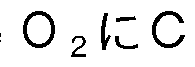 がドープさ れたことで格子歪ができ酸素空孔を作りやすくする。 これがクロムドープに より、 ドープされていない 06〇 2よりも大きな酸素移動度が得られた理由と 推察される。
\¥0 2020/175444 36 卩(:170? 2020 /007378
がドープさ れたことで格子歪ができ酸素空孔を作りやすくする。 これがクロムドープに より、 ドープされていない 06〇 2よりも大きな酸素移動度が得られた理由と 推察される。
\¥0 2020/175444 36 卩(:170? 2020 /007378
[0177] そして、 〇6〇2と比較して、 マグネタイ ト構造の 6の 2価と 3価との間 の遷移はより生じやすいことが知られており、 還元場では 0価にまで還元さ れる。 これは、 自動車触媒開発においても見出されていたが、 さらに、 「 のドープにより、 より酸素空孔が生じやすくなっているものと推察される。
[0178] 以上の結果から、 実施例の酸素キャリアは、 いずれも、 6 0 0 °〇以下の低 温廃熱レベルでも十分な〇 3(3が得られるといえる。
[0179] <試験例 2 - 2 > 酸素キャリアにおける平均一次粒子径と粒子内の酸素空 孔形成性との関係
〔試験方法〕
実施例 2 - 1 - 2で用いた〇 6〇2ナノキユーブについて、 T E M (透過型 電子顕微鏡) により酸素キャリア粒子の画像を撮像し、 その丁巳1\/1像を画像 解析 ·画像計測ソフトウェアにより解析することで、 平均一次粒子径と粒子 内の酸素空孔形成性との関係を調べた。 結果を図 1 1〜図 1 4に示す。
[0180] 〔結果〕
図 1 1は、 上段から平均一次粒子径が 1 1
 9 n 、 8 n 01、 7 1^ 111、 6 1^ 111、 5
 であるときのセリウム元素の原子カラム (横軸
) と、 0 6 3 +/ (〇6 3 + +〇6 4 +) , すなわち粒子内の酸素空孔形成性 (縦 軸) との関係を示す。 図 1 1 によると、 平均一次粒子径が 1 1 门 01である場 合、 表面付近で酸素欠陥が現れているのに対し、 平均一次粒子径が小さくな ればなるほど、 セリウム元素の中心にまで酸素欠陥が現れていることが分か る。 セリウム元素の内部にまで酸素空孔が広がることは、 酸素原子が移動し ており、 ナノ粒子表面だけでなく、 粒子全域の酸素が使えていることを意味 する。 これにより、 酸素キャリアの平均一次粒子径が小さいほど、 反応物質 との暴露表面積 (接触可能性) の最大化と、 格子歪による酸素空孔易形成性 とを実現できるといえる。 そして、 高い〇3〇が得られた要因がここに見ら れる。
[0181 ] 図 1 2 (八) は、 試験例 2 - 2におけるセリウム元素の丁巳 IV!像を示す。
図 1 2 (巳) は、 原子間の歪を示す。 明るく見えている部分は大きな歪を持
\¥0 2020/175444 37 卩(:170? 2020 /007378
っている部分である。
[0182] 図 1 2の (八) のうち、 左の画像は、 平均一次粒子径が 1 1 门 であるセ リウム元素の丁巳 IV!像であり、 右の画像は平均一次粒子径が 6 n であるセ リウム元素の丁巳 IV!像である。 左右それぞれの丁巳 IV!像にある点がセリウム 原子を示し、 4つのセリウム原子に囲まれた領域が分子内に酸素を取り込み 得る領域である。
[0183] 図 1 2の (巳) は、 図 6の (八) で示した丁巳1\/1像を解析し、 セリウム原 子間の歪みを可視化したものである。 色がグレーである場合 (数値が 0に近 い色である場合) 、 原子間の歪みが小さいことを示す。 そして、 色が薄いほ ど (白色に近いほど) 、 原子間の空隙が拡張し、 空隙に酸素を取り込み易い 状態にあることを示す。 他方、 色が濃いほど (黒色に近いほど) 、 原子間の 空隙が縮んでおり、 空隙に酸素を取り込みづらい状態にあることを示す。 図 1 2 (巳) によると、 平均一次粒子径が 1 1 n であるセリウムナノ粒子で は、 粒子の表面では原子間の空隙の拡張が認められる一方、 粒子の中心では 原子間の空隙の拡張がほとんど認められない。 他方、 平均一次粒子径が 6 n であるセリウムナノ粒子では、 粒子の全体で原子間の空隙の拡張が認めら れる。 これにより、 酸素キャリアの平均一次粒子径が小さいほど、 格子歪に よる酸素空孔易形成性を実現できるといえる。
[0184] 図 1 3は、 図 1 2の (八) で示した丁巳 IV!像について、 セリウム元素の左 から右に向かうときの格子が拡張する割合を示す。 図 1 3の (八) は、 平均 —次粒子径が 1 1 门 であるセリウム元素についての状態であり、 図 1 3の (巳) は、 平均一次粒子径が 6 n
 であるセリウム元素についての状態であ る。 図 1 3からも、 酸素キャリアの平均一次粒子径が小さいほど、 原子間に おける格子の拡張が認められ、 格子歪による酸素空孔易形成性を実現できる ことが裏付けられる。
[0185] 図 1 4は、 セリウムナノ粒子における格子の拡張が認められる割合と、 セ リウム原子間に酸素空孔を形成するのに必要なエネルギーとの関係を示した 図である。 図 1 4によると、 格子の拡張が認められる割合が大きい粒子ほど
\¥02020/175444 38 卩(:170? 2020 /007378
、 セリウム原子間に酸素空孔を形成するのに必要なエネルギーが小さいこと が分かる。 したがって、 酸素キャリアの平均一次粒子径が小さく、 セリウム 原子間における格子の拡張が元素全体に広く認められるほど、 セリウム原子 間に酸素空孔を形成し易いといえる。 これが、 図 1 0で極めて高い 03〇が 得られた要因である。
[0186] 図 1 2及び図 1 3で確認できた歪ができれば、 酸素空孔を作りやすいこと 酸素が移動しやすいことを示しており、 図 1 0で示した高い 03(3が得られ たのは、 露出面制御されたナノサイズの粒子が、 さらに小さくなることで粒 子内全体に歪が生じ、 それにより酸素移動が促進されたからであることがわ かる。
[0187] <試験例 2-3> バッチ反応器でのメタンー酸素キャリア反応実験
〔試験例 2-3- 1〕 酸素キャリアが酸化セリウム (<36〇2) の場合 [〇〇2生成]
実施例 2 - 1 - 1で使用した酸化セリウム (〇 6〇2) を酸化状態にし、 1 台の反応器に充填した。 そして、 〇1~14を導入し、 300°〇で〇1~14を酸化さ せ、 二酸化炭素の生成量の経時変化を測定した。 その際、 反応圧力は、 〇. 61\/1 3であった。 結果を図 1 5 (八) に示す。
[0188] [1~12生成]
実施例 2 _ 1 _ 1で使用した酸化セリウムを還元状態にし、 1台の反応器 に充填した。 そして、 水蒸気を導入し、 300°〇で還元状態の酸化セリウム を酸化させ、 水素の生成量の経時変化を測定した。 その際、 反応圧力は、 8 IV! 8であった。 結果を図 1 5 (巳) に示す。
[0189] 〔試験例 2 -3 -2〕 酸素キャリアが酸化鉄ージルコニア系複合酸化物 ( ㊀〇父一 「〇2) の場合
[〇〇2生成]
実施例 2_ 1 _ 4で使用した酸化鉄ージルコニア系複合酸化物 ( 6〇父 — 「〇2) を酸化状態にし、 1台の反応器に充填した。 そして、 〇1~14を導 入し、 400°〇で(31~14を酸化させ、 二酸化炭素の生成量の経時変化を測定し
\¥02020/175444 39 卩(:170? 2020 /007378
た。 その際、 反応圧力は、 〇. であった。 結果を図 1 6 (八) に示 す。
[0190] [1~12生成]
実施例 2 _ 1 _4で使用した酸化鉄ージルコニア系複合酸化物を還元状態 にし、 1台の反応器に充填した。 そして、 水蒸気を導入し、 400°〇で還元 状態の複合酸化物を酸化させ、 水素の生成量の経時変化を測定した。 その際 、 反応圧力は、 81\/1 3であった。 結果を図 1 6 (巳) に示す。
[0191] 〔結果〕
酸素キャリアが酸化セリウム (〇6〇2) の場合、 〇1~14から二酸化炭素の 生成反応における反応速度定数 は、 〇. 060 [ 丨 n-l] であり、 水蒸 気から水素の生成反応における反応速度定数 は、 〇. 044 [〇! I n-l] であった。 それに対し、 酸素キャリアが酸化鉄ージルコニア系複合酸化物の 場合、 〇1~14から二酸化炭素の生成反応における反応速度定数 は、 0. 07 I n-l] であり、 水蒸気から水素の生成反応における反応速度定数 は 、 〇. 1 35 [〇1 丨 1^-1] であった。 このことからも、 本反応系において、 酸化鉄ージルコニア系複合酸化物が酸素キャリアとして特に優れることが裏 付けられる。
[0192] <試験例 2— 4 > プロセススケールのシミュレーシヨン
酸素キャリアとして、 実施例 2- 1 - 1で使用した酸化セリウム (〇6〇2 ) 、 実施例 2- 1 -3で使用したクロムドープ酸化セリウム (〇 「一〇6〇2 ) 、 実施例 2— 1 _ 4で使用した酸化鉄ージルコニア系複合酸化物 ( 6〇 父_ 「〇2) のそれぞれについて、 プロセススケールをシミュレートした。 メタノール合成装置のうち、 メタンから水素と炭素化合物とを生成する第 1 装置については、 図 1 に示したケミカルループ式の製造システム 1であるも のとした。 また、 水素と炭素化合物からメタノールを合成する第 2装置につ いては、 図 8に例示される従来公知の態様とした。 メタノールを 1年間に 1 00万トン製造するのに十分な水素及び炭素化合物を製造するの必要なケミ カルループ式製造システム 1 (図 1) の容量を検討した。 結果を図 1 7に示
\¥0 2020/175444 40 卩(:170? 2020 /007378
す。
[0193] 図 1 7は、 図 1 に示したケミカルループ式製造システム 1の工業的に適し た装置規模をシミュレートした結果である。 図 1 7の横軸は、 ケミカルルー プ式製造システム 1 (図 1) の運転温度であり、 縦軸は、 想定量のメタノー ルを製造するのに必要なケミカルループ式製造システム 1 (図 1) の容量を 示す。 図 1 0で〇3〇が得られ、 図 1 5及び図 1 6で反応の速度が得られる ので、 ケミカルループプロセスのリアクターのサイズが計算できる。 ここで は、 年間 1 0 0万トンのメタノール生産を行う場合に必要なリアクターサイ ズを示している。
[0194] 運転温度が 5 0 0 °〇である場合、 酸素キャリアが酸化セリウム (〇6〇2) であるとき、 ケミカルループ式製造システム 1 (図 1) の容量は、 約 5 0 0 0 3である。
[0195] それに対し、 酸素キャリアがクロムドープ酸化セリウム (〇 「一〇6〇2) であるとき、 ケミカルループ式製造システム 1 (図 1) の容量は、 約 1 0 0 0 3で足り、 酸素キャリアが酸化鉄ージルコニア系複合酸化物 ( 6〇 X _ 「〇2) であるとき、 ケミカルループ式製造システム 1 (図 1) の容量は、 約 1 0 0 3で足りる。
[0196] このことから、 酸素キャリアの種類を適切に選択することで、 従来の合成 システムに比べて装置を小型化できることが期待される。 符号の説明
[0197] 1 水素及び合成ガスの製造システム
1 0 第 1反応器
1 1 第 1入口
1 2 第 1出口
2 0 第 2反応器
2 1 第 2入口
2 2 第 2出口
Claims
[請求項 1 ] 水素及び合成ガスの製造システムと、
前記水素及び前記合成ガスの少なくとも一部を原料としてメタノー ルを合成するメタノール合成システムとを備え、
前記水素及び合成ガスの製造システムは、
酸化された酸素キヤリアと炭化水素系材料とを反応させ、 水素と 炭素酸化物とを生成する第 1反応器と、
還元された酸素キヤリアと水とを反応させ、 前記酸化された酸素 キヤリアと水素とを生成する第 2反応器とを有し、
前記酸素キヤリアは、 前記第 1反応器と前記第 2反応器とを循環 流動する、 メタノール合成装置。
[請求項 2] 水素及び合成ガスの製造システムと、
前記水素及び前記合成ガスの少なくとも一部を原料としてメタノー ルを合成するメタノール合成システムとを備え、
前記水素及び合成ガスの製造システムは、
酸素キヤリアが充填された複数の反応器を備え、
前記複数の反応器は、 炭化水素系材料又は水を導入可能に構成さ れ、
前記複数の反応器のうち、 前記酸素キヤリアが酸化された状態に ある反応器には、 前記炭化水素系材料が導入され、 前記炭化水素系材 料を酸化させることが可能であり、
前記複数の反応器のうち、 前記酸素キヤリアが還元された状態に ある反応器には、 前記水が導入され、 水素を合成することが可能であ り、
前記複数の反応器のそれぞれに充填された前記酸素キヤリアの状 態によって、 前記反応器の導入する材料を前記炭化水素系材料と前記 水との間で切り替え可能である、 メタノール合成装置。
[請求項 3] 反応温度が 6 0 0 °〇以下である、 請求項 1又は 2に記載の装置。
\¥0 2020/175444 42 卩(:170? 2020 /007378
[請求項 4] 前記酸素キャリアは、 酸化セリウム (〇6〇2) 、 クロムドープ酸 化セリウム (<3 「_〇6〇2) 、 酸化鉄ージルコニア系複合酸化物 ( 6〇父一2 「〇2) 、 酸化鉄 ( 6 2〇3) 、 酸化インジウム ( I 门 2〇3) 、 イッ トリウム安定化酸化ジルコニウム (丫3 ) 、 酸化ス カンジウムドープ酸化ジルコニウム (3〇 3 ) 、 酸化スカンジウム (3〇 2 0 3) . 酸化ランタンガリウム
 ランタンス トロンチウムマンガナイ ト
 、 ガドリニウムドープ酸化セリ ウム (〇 一〇6〇2) 、 酸化モリブデン (1\/1〇〇3) 、 酸化マンガ ン (IV! n〇 3) 、 ランタンストロンチウムコノくノレトフェライ ト (1_ 3 〇 ) 、 ランタンストロンチウムフェライ ト (1_ 3 ) 、 四酸化三コ バルト (〇〇3〇4) 、 酸化コバルト 丨 丨 (〇〇〇) 、 酸化バナジウ ム ( 2〇5) 、 及びセリア ·ジルコニア固溶体からなる群から選択 される 1種以上を含む、 請求項 1から 3のいずれか 1項に記載の装置
[請求項 5] 前記反応器の内部に前記酸素キャリア及び金属助触媒が共存されて いる、 及び/又は前記酸素キャリアに金属助触媒が担持されている、 請求項 1から 4のいずれか 1項に記載の装置。
[請求項 6] 前記酸素キャリアの一次粒子の平均粒子径が 1 以下である、 請 求項 1から 5のいずれか 1項に記載の装置。
[請求項 7] 前記酸素キャリアの形状が最も活性な露出面を有する形状である、 請求項 1から 6のいずれか 1項に記載のシステム。
[請求項 8] 酸化された酸素キャリアと炭化水素系材料とを反応させ、 水素と炭 素酸化物とを生成する第 1反応工程と、
還元された酸素キャリアと水とを反応させ、 前記酸化された酸素キ ャリアと水素とを生成する第 2反応工程と、
前記第 1反応工程及び前記第 2反応工程の反応生成物である水素の 少なくとも一部と、 前記第 1反応工程の反応生成物である炭素酸化物 の少なくとも一部とを原料としてメタノールを合成する第 3反応工程
\¥0 2020/175444 43 卩(:170? 2020 /007378
と、
を含み、
前記酸素キヤリアは、 前記第 1反応工程と前記第 2反応工程との間 で循環流動する、 メタノール合成方法。
[請求項 9] 酸素キヤリアが充填された複数の反応器を備え、
前記複数の反応器は、 炭化水素系材料又は水を導入可能に構成され 前記複数の反応器のうち、 前記酸素キヤリアが酸化された状態にあ る反応器では、 前記炭化水素を導入し、 前記炭化水素系材料を酸化さ せる第 1反応工程を行い、
前記複数の反応器のうち、 前記酸素キヤリアが還元された状態にあ る反応器には、 前記水が導入され、 前記水を還元させる第 2反応工程 を行い、
前記複数の反応器のそれぞれに充填された前記酸素キヤリアの状態 によって、 前記反応器の導入する材料を前記炭化水素系材料と前記酸 化剤との間で切り替える切替工程と、
前記第 1反応工程及び前記第 2反応工程の反応生成物である水素の 少なくとも一部と、 前記第 1反応工程の反応生成物である炭素酸化物 の少なくとも一部とを原料としてメタノールを合成する第 3反応工程 と、
をさらに含む、 メタノール合成方法。
Priority Applications (1)
| Application Number | Priority Date | Filing Date | Title |
|---|---|---|---|
| JP2021502249A JP7451865B2 (ja) | 2019-02-27 | 2020-02-25 | メタノール合成システム及びその方法 |
Applications Claiming Priority (2)
| Application Number | Priority Date | Filing Date | Title |
|---|---|---|---|
| JP2019-034368 | 2019-02-27 | ||
| JP2019034368 | 2019-02-27 |
Publications (1)
| Publication Number | Publication Date |
|---|---|
| WO2020175444A1 true WO2020175444A1 (ja) | 2020-09-03 |
Family
ID=72239181
Family Applications (1)
| Application Number | Title | Priority Date | Filing Date |
|---|---|---|---|
| PCT/JP2020/007378 Ceased WO2020175444A1 (ja) | 2019-02-27 | 2020-02-25 | メタノール合成システム及びその方法 |
Country Status (2)
| Country | Link |
|---|---|
| JP (1) | JP7451865B2 (ja) |
| WO (1) | WO2020175444A1 (ja) |
Cited By (1)
| Publication number | Priority date | Publication date | Assignee | Title |
|---|---|---|---|---|
| CN116371408A (zh) * | 2023-04-24 | 2023-07-04 | 华中科技大学 | Sr-Fe基氧载体及其制备方法和在重整制氢/CO中的应用 |
Citations (3)
| Publication number | Priority date | Publication date | Assignee | Title |
|---|---|---|---|---|
| WO2002100773A1 (en) * | 2001-04-24 | 2002-12-19 | Praxair Technology, Inc. | Syngas production utilizing an oxygen transport membrane |
| JP2012219068A (ja) * | 2011-04-11 | 2012-11-12 | Chiyoda Kako Kensetsu Kk | 高効率メタノール製造方法 |
| JP2015131892A (ja) * | 2014-01-10 | 2015-07-23 | 国立大学法人東北大学 | 水共存下での重質炭化水素の接触分解方法 |
-
2020
- 2020-02-25 WO PCT/JP2020/007378 patent/WO2020175444A1/ja not_active Ceased
- 2020-02-25 JP JP2021502249A patent/JP7451865B2/ja active Active
Patent Citations (3)
| Publication number | Priority date | Publication date | Assignee | Title |
|---|---|---|---|---|
| WO2002100773A1 (en) * | 2001-04-24 | 2002-12-19 | Praxair Technology, Inc. | Syngas production utilizing an oxygen transport membrane |
| JP2012219068A (ja) * | 2011-04-11 | 2012-11-12 | Chiyoda Kako Kensetsu Kk | 高効率メタノール製造方法 |
| JP2015131892A (ja) * | 2014-01-10 | 2015-07-23 | 国立大学法人東北大学 | 水共存下での重質炭化水素の接触分解方法 |
Non-Patent Citations (3)
| Title |
|---|
| ADSCHIRI, TADAFUMI: "Continuous Production of Nanoparticles by Supercritical Hydrothermal Synthesis Nanoparticles Synthesis, -Nanohybrid Materials,and Surface Controlled Nanocatalysts-", THE MICROMERITICS, vol. 2017, no. 60, 2017, pages 24 - 32 * |
| OGO, SHUHEI ET AL: "Methane-carbon dioxide and catalyst for hydrogen", CHEMISTRY AND EDUCATION, vol. 66, no. 2, 2018, pages 68 - 71 * |
| YOKO, A ET AL.: "Process assessments for low-temperature methane reforming using oxygen carrier metal oxide nanoparticles", CHEMICAL ENGINEERING AND PROCESSING - PROCESS INTENSIFICATION, vol. 142, pages 107531 * |
Cited By (1)
| Publication number | Priority date | Publication date | Assignee | Title |
|---|---|---|---|---|
| CN116371408A (zh) * | 2023-04-24 | 2023-07-04 | 华中科技大学 | Sr-Fe基氧载体及其制备方法和在重整制氢/CO中的应用 |
Also Published As
| Publication number | Publication date |
|---|---|
| JP7451865B2 (ja) | 2024-03-19 |
| JPWO2020175444A1 (ja) | 2020-09-03 |
Similar Documents
| Publication | Publication Date | Title |
|---|---|---|
| Sun et al. | Performance of CeO2-modified iron-based oxygen carrier in the chemical looping hydrogen generation process | |
| Tian et al. | Calcium-looping reforming of methane realizes in situ CO2 utilization with improved energy efficiency | |
| Huang et al. | Exploration of reaction mechanisms on hydrogen production through chemical looping steam reforming using NiFe2O4 oxygen carrier | |
| Yin et al. | A Ce–Fe oxygen carrier with a core–shell structure for chemical looping steam methane reforming | |
| Galvita et al. | CeO2-modified Fe2O3 for CO2 utilization via chemical looping | |
| JP7450965B2 (ja) | 炭化水素低温改質システム、並びに水素及び/又は合成ガスの低温での製造方法 | |
| Jin et al. | CO oxidation catalyzed by two-dimensional Co3O4/CeO2 nanosheets | |
| Zhang et al. | Octahedral core–shell bimetallic catalysts M@ UIO-67 (M= Pt–Pd nanoparticles, Pt–Pd nanocages): metallic nanocages that enhanced CO2 conversion | |
| Sarshar et al. | Development of sinter-resistant core–shell LaMn x Fe1–x O3@ mSiO2 oxygen carriers for chemical looping combustion | |
| Zeng et al. | Tuning the support properties toward higher CO2 conversion during a chemical looping scheme | |
| Xiao et al. | Methane dry reforming by Ni–Cu nanoalloys anchored on periclase-phase MgAlO x nanosheets for enhanced syngas production | |
| EP3037162A1 (en) | Method for treating organic matter in the presence of water, contact reaction device and system including same, and method for recovering waste heat from low-temperature heat source | |
| Zeng et al. | Ternary mixed spinel oxides as oxygen carriers for chemical looping hydrogen production operating at 550° C | |
| Cheng et al. | Direct reduction of nickel catalyst with model bio-compounds | |
| Saupsor et al. | Bifunctional catalyst NiFe–MgAl for hydrogen production from chemical looping ethanol reforming | |
| Gu et al. | Natural iron ore as oxygen carrier modified with rare earth metal for chemical looping hydrogen production | |
| He et al. | CoxFe1-xFeAlO4-δ as highly active oxygen carriers for enhanced chemical looping hydrogen production | |
| Liao et al. | Enhancing effect of Mn2+ substitution in CuAl2O4 spinel for methanol steam reforming in a microreactor | |
| Zhang et al. | Hydrogen by glycerol chemical looping reforming over Fe-based oxygen carriers derived from LaNi1− xFexO3-λ perovskite | |
| Wang et al. | Lattice oxygen regulation of perovskites for chemical looping oxidative dehydrogenation of ethylbenzene to styrene | |
| Li et al. | ZIF-derived catalyst with inverse ZnO/Co structure for efficient CO2 methanation | |
| Sayyed et al. | Recent insights into the production of syngas and hydrogen using chemical looping-steam reforming (CL-SR) | |
| Hui et al. | Hydrogen storage properties of modified fumed-Fe-dust generated from a revolving furnace at a steel industry | |
| Wang et al. | Stabilizing Ni-CeO x bifunctional Nanoparticles on activated alumina to enhance carbon resistance for dry reforming of methane | |
| Wang et al. | Hydrogen Production by Biomass Model Syngas Chemical Looping over Ce/Zr Doped NiFe2O4 Oxygen Carrier |
Legal Events
| Date | Code | Title | Description |
|---|---|---|---|
| 121 | Ep: the epo has been informed by wipo that ep was designated in this application |
Ref document number: 20763072 Country of ref document: EP Kind code of ref document: A1 |
|
| ENP | Entry into the national phase |
Ref document number: 2021502249 Country of ref document: JP Kind code of ref document: A |
|
| NENP | Non-entry into the national phase |
Ref country code: DE |
|
| 122 | Ep: pct application non-entry in european phase |
Ref document number: 20763072 Country of ref document: EP Kind code of ref document: A1 |