WO2020174325A2 - Multi-aperture cameras with at least one two state zoom camera - Google Patents
Multi-aperture cameras with at least one two state zoom camera Download PDFInfo
- Publication number
- WO2020174325A2 WO2020174325A2 PCT/IB2020/051405 IB2020051405W WO2020174325A2 WO 2020174325 A2 WO2020174325 A2 WO 2020174325A2 IB 2020051405 W IB2020051405 W IB 2020051405W WO 2020174325 A2 WO2020174325 A2 WO 2020174325A2
- Authority
- WO
- WIPO (PCT)
- Prior art keywords
- lens
- camera
- zoom
- tele
- module
- Prior art date
Links
- 230000003287 optical effect Effects 0.000 claims abstract description 140
- 230000007246 mechanism Effects 0.000 claims description 37
- 229910001285 shape-memory alloy Inorganic materials 0.000 claims description 26
- 230000005291 magnetic effect Effects 0.000 claims description 13
- 230000010287 polarization Effects 0.000 claims description 11
- 238000007667 floating Methods 0.000 claims description 4
- 238000013461 design Methods 0.000 description 64
- 238000000429 assembly Methods 0.000 description 22
- 230000000712 assembly Effects 0.000 description 21
- 238000000034 method Methods 0.000 description 21
- 230000008859 change Effects 0.000 description 17
- 230000008569 process Effects 0.000 description 9
- 230000006835 compression Effects 0.000 description 6
- 238000007906 compression Methods 0.000 description 6
- 238000006073 displacement reaction Methods 0.000 description 6
- 239000011521 glass Substances 0.000 description 6
- 239000000463 material Substances 0.000 description 5
- 230000008878 coupling Effects 0.000 description 3
- 238000010168 coupling process Methods 0.000 description 3
- 238000005859 coupling reaction Methods 0.000 description 3
- 230000000694 effects Effects 0.000 description 3
- 230000005294 ferromagnetic effect Effects 0.000 description 3
- 239000000758 substrate Substances 0.000 description 3
- 230000001276 controlling effect Effects 0.000 description 2
- 230000002596 correlated effect Effects 0.000 description 2
- 239000003302 ferromagnetic material Substances 0.000 description 2
- 230000006870 function Effects 0.000 description 2
- 230000012447 hatching Effects 0.000 description 2
- 238000010137 moulding (plastic) Methods 0.000 description 2
- 238000012545 processing Methods 0.000 description 2
- 230000006641 stabilisation Effects 0.000 description 2
- 238000011105 stabilization Methods 0.000 description 2
- 238000004804 winding Methods 0.000 description 2
- 241000238631 Hexapoda Species 0.000 description 1
- 238000004026 adhesive bonding Methods 0.000 description 1
- 230000009286 beneficial effect Effects 0.000 description 1
- 229910010293 ceramic material Inorganic materials 0.000 description 1
- 230000007423 decrease Effects 0.000 description 1
- 238000010586 diagram Methods 0.000 description 1
- 230000009977 dual effect Effects 0.000 description 1
- 239000000428 dust Substances 0.000 description 1
- 230000008278 dynamic mechanism Effects 0.000 description 1
- 238000005516 engineering process Methods 0.000 description 1
- 230000007613 environmental effect Effects 0.000 description 1
- 238000001914 filtration Methods 0.000 description 1
- 238000010438 heat treatment Methods 0.000 description 1
- 238000003384 imaging method Methods 0.000 description 1
- 238000010348 incorporation Methods 0.000 description 1
- 230000005415 magnetization Effects 0.000 description 1
- 238000004519 manufacturing process Methods 0.000 description 1
- 230000013011 mating Effects 0.000 description 1
- 229910052751 metal Inorganic materials 0.000 description 1
- 239000002184 metal Substances 0.000 description 1
- 238000012986 modification Methods 0.000 description 1
- 230000004048 modification Effects 0.000 description 1
- TWNQGVIAIRXVLR-UHFFFAOYSA-N oxo(oxoalumanyloxy)alumane Chemical compound O=[Al]O[Al]=O TWNQGVIAIRXVLR-UHFFFAOYSA-N 0.000 description 1
- 230000002040 relaxant effect Effects 0.000 description 1
- 230000003068 static effect Effects 0.000 description 1
- 238000012546 transfer Methods 0.000 description 1
Classifications
-
- H—ELECTRICITY
- H04—ELECTRIC COMMUNICATION TECHNIQUE
- H04N—PICTORIAL COMMUNICATION, e.g. TELEVISION
- H04N23/00—Cameras or camera modules comprising electronic image sensors; Control thereof
- H04N23/50—Constructional details
- H04N23/55—Optical parts specially adapted for electronic image sensors; Mounting thereof
-
- G—PHYSICS
- G03—PHOTOGRAPHY; CINEMATOGRAPHY; ANALOGOUS TECHNIQUES USING WAVES OTHER THAN OPTICAL WAVES; ELECTROGRAPHY; HOLOGRAPHY
- G03B—APPARATUS OR ARRANGEMENTS FOR TAKING PHOTOGRAPHS OR FOR PROJECTING OR VIEWING THEM; APPARATUS OR ARRANGEMENTS EMPLOYING ANALOGOUS TECHNIQUES USING WAVES OTHER THAN OPTICAL WAVES; ACCESSORIES THEREFOR
- G03B5/00—Adjustment of optical system relative to image or object surface other than for focusing
- G03B5/04—Vertical adjustment of lens; Rising fronts
-
- G—PHYSICS
- G02—OPTICS
- G02B—OPTICAL ELEMENTS, SYSTEMS OR APPARATUS
- G02B7/00—Mountings, adjusting means, or light-tight connections, for optical elements
- G02B7/02—Mountings, adjusting means, or light-tight connections, for optical elements for lenses
- G02B7/04—Mountings, adjusting means, or light-tight connections, for optical elements for lenses with mechanism for focusing or varying magnification
- G02B7/10—Mountings, adjusting means, or light-tight connections, for optical elements for lenses with mechanism for focusing or varying magnification by relative axial movement of several lenses, e.g. of varifocal objective lens
-
- G—PHYSICS
- G02—OPTICS
- G02B—OPTICAL ELEMENTS, SYSTEMS OR APPARATUS
- G02B13/00—Optical objectives specially designed for the purposes specified below
- G02B13/001—Miniaturised objectives for electronic devices, e.g. portable telephones, webcams, PDAs, small digital cameras
- G02B13/0015—Miniaturised objectives for electronic devices, e.g. portable telephones, webcams, PDAs, small digital cameras characterised by the lens design
- G02B13/002—Miniaturised objectives for electronic devices, e.g. portable telephones, webcams, PDAs, small digital cameras characterised by the lens design having at least one aspherical surface
- G02B13/0045—Miniaturised objectives for electronic devices, e.g. portable telephones, webcams, PDAs, small digital cameras characterised by the lens design having at least one aspherical surface having five or more lenses
-
- G—PHYSICS
- G02—OPTICS
- G02B—OPTICAL ELEMENTS, SYSTEMS OR APPARATUS
- G02B13/00—Optical objectives specially designed for the purposes specified below
- G02B13/001—Miniaturised objectives for electronic devices, e.g. portable telephones, webcams, PDAs, small digital cameras
- G02B13/0055—Miniaturised objectives for electronic devices, e.g. portable telephones, webcams, PDAs, small digital cameras employing a special optical element
- G02B13/0065—Miniaturised objectives for electronic devices, e.g. portable telephones, webcams, PDAs, small digital cameras employing a special optical element having a beam-folding prism or mirror
-
- G—PHYSICS
- G02—OPTICS
- G02B—OPTICAL ELEMENTS, SYSTEMS OR APPARATUS
- G02B13/00—Optical objectives specially designed for the purposes specified below
- G02B13/001—Miniaturised objectives for electronic devices, e.g. portable telephones, webcams, PDAs, small digital cameras
- G02B13/009—Miniaturised objectives for electronic devices, e.g. portable telephones, webcams, PDAs, small digital cameras having zoom function
-
- G—PHYSICS
- G02—OPTICS
- G02B—OPTICAL ELEMENTS, SYSTEMS OR APPARATUS
- G02B15/00—Optical objectives with means for varying the magnification
- G02B15/14—Optical objectives with means for varying the magnification by axial movement of one or more lenses or groups of lenses relative to the image plane for continuously varying the equivalent focal length of the objective
- G02B15/143—Optical objectives with means for varying the magnification by axial movement of one or more lenses or groups of lenses relative to the image plane for continuously varying the equivalent focal length of the objective having three groups only
- G02B15/1431—Optical objectives with means for varying the magnification by axial movement of one or more lenses or groups of lenses relative to the image plane for continuously varying the equivalent focal length of the objective having three groups only the first group being positive
- G02B15/143103—Optical objectives with means for varying the magnification by axial movement of one or more lenses or groups of lenses relative to the image plane for continuously varying the equivalent focal length of the objective having three groups only the first group being positive arranged ++-
-
- G—PHYSICS
- G02—OPTICS
- G02B—OPTICAL ELEMENTS, SYSTEMS OR APPARATUS
- G02B27/00—Optical systems or apparatus not provided for by any of the groups G02B1/00 - G02B26/00, G02B30/00
- G02B27/64—Imaging systems using optical elements for stabilisation of the lateral and angular position of the image
- G02B27/646—Imaging systems using optical elements for stabilisation of the lateral and angular position of the image compensating for small deviations, e.g. due to vibration or shake
-
- G—PHYSICS
- G02—OPTICS
- G02B—OPTICAL ELEMENTS, SYSTEMS OR APPARATUS
- G02B7/00—Mountings, adjusting means, or light-tight connections, for optical elements
- G02B7/02—Mountings, adjusting means, or light-tight connections, for optical elements for lenses
- G02B7/04—Mountings, adjusting means, or light-tight connections, for optical elements for lenses with mechanism for focusing or varying magnification
- G02B7/09—Mountings, adjusting means, or light-tight connections, for optical elements for lenses with mechanism for focusing or varying magnification adapted for automatic focusing or varying magnification
-
- G—PHYSICS
- G02—OPTICS
- G02B—OPTICAL ELEMENTS, SYSTEMS OR APPARATUS
- G02B7/00—Mountings, adjusting means, or light-tight connections, for optical elements
- G02B7/02—Mountings, adjusting means, or light-tight connections, for optical elements for lenses
- G02B7/04—Mountings, adjusting means, or light-tight connections, for optical elements for lenses with mechanism for focusing or varying magnification
- G02B7/10—Mountings, adjusting means, or light-tight connections, for optical elements for lenses with mechanism for focusing or varying magnification by relative axial movement of several lenses, e.g. of varifocal objective lens
- G02B7/102—Mountings, adjusting means, or light-tight connections, for optical elements for lenses with mechanism for focusing or varying magnification by relative axial movement of several lenses, e.g. of varifocal objective lens controlled by a microcomputer
-
- G—PHYSICS
- G02—OPTICS
- G02B—OPTICAL ELEMENTS, SYSTEMS OR APPARATUS
- G02B7/00—Mountings, adjusting means, or light-tight connections, for optical elements
- G02B7/02—Mountings, adjusting means, or light-tight connections, for optical elements for lenses
- G02B7/04—Mountings, adjusting means, or light-tight connections, for optical elements for lenses with mechanism for focusing or varying magnification
- G02B7/10—Mountings, adjusting means, or light-tight connections, for optical elements for lenses with mechanism for focusing or varying magnification by relative axial movement of several lenses, e.g. of varifocal objective lens
- G02B7/105—Mountings, adjusting means, or light-tight connections, for optical elements for lenses with mechanism for focusing or varying magnification by relative axial movement of several lenses, e.g. of varifocal objective lens with movable lens means specially adapted for focusing at close distances
-
- G—PHYSICS
- G03—PHOTOGRAPHY; CINEMATOGRAPHY; ANALOGOUS TECHNIQUES USING WAVES OTHER THAN OPTICAL WAVES; ELECTROGRAPHY; HOLOGRAPHY
- G03B—APPARATUS OR ARRANGEMENTS FOR TAKING PHOTOGRAPHS OR FOR PROJECTING OR VIEWING THEM; APPARATUS OR ARRANGEMENTS EMPLOYING ANALOGOUS TECHNIQUES USING WAVES OTHER THAN OPTICAL WAVES; ACCESSORIES THEREFOR
- G03B13/00—Viewfinders; Focusing aids for cameras; Means for focusing for cameras; Autofocus systems for cameras
- G03B13/32—Means for focusing
- G03B13/34—Power focusing
- G03B13/36—Autofocus systems
-
- G—PHYSICS
- G03—PHOTOGRAPHY; CINEMATOGRAPHY; ANALOGOUS TECHNIQUES USING WAVES OTHER THAN OPTICAL WAVES; ELECTROGRAPHY; HOLOGRAPHY
- G03B—APPARATUS OR ARRANGEMENTS FOR TAKING PHOTOGRAPHS OR FOR PROJECTING OR VIEWING THEM; APPARATUS OR ARRANGEMENTS EMPLOYING ANALOGOUS TECHNIQUES USING WAVES OTHER THAN OPTICAL WAVES; ACCESSORIES THEREFOR
- G03B17/00—Details of cameras or camera bodies; Accessories therefor
- G03B17/02—Bodies
- G03B17/17—Bodies with reflectors arranged in beam forming the photographic image, e.g. for reducing dimensions of camera
-
- G—PHYSICS
- G03—PHOTOGRAPHY; CINEMATOGRAPHY; ANALOGOUS TECHNIQUES USING WAVES OTHER THAN OPTICAL WAVES; ELECTROGRAPHY; HOLOGRAPHY
- G03B—APPARATUS OR ARRANGEMENTS FOR TAKING PHOTOGRAPHS OR FOR PROJECTING OR VIEWING THEM; APPARATUS OR ARRANGEMENTS EMPLOYING ANALOGOUS TECHNIQUES USING WAVES OTHER THAN OPTICAL WAVES; ACCESSORIES THEREFOR
- G03B3/00—Focusing arrangements of general interest for cameras, projectors or printers
- G03B3/10—Power-operated focusing
-
- G—PHYSICS
- G03—PHOTOGRAPHY; CINEMATOGRAPHY; ANALOGOUS TECHNIQUES USING WAVES OTHER THAN OPTICAL WAVES; ELECTROGRAPHY; HOLOGRAPHY
- G03B—APPARATUS OR ARRANGEMENTS FOR TAKING PHOTOGRAPHS OR FOR PROJECTING OR VIEWING THEM; APPARATUS OR ARRANGEMENTS EMPLOYING ANALOGOUS TECHNIQUES USING WAVES OTHER THAN OPTICAL WAVES; ACCESSORIES THEREFOR
- G03B30/00—Camera modules comprising integrated lens units and imaging units, specially adapted for being embedded in other devices, e.g. mobile phones or vehicles
-
- G—PHYSICS
- G03—PHOTOGRAPHY; CINEMATOGRAPHY; ANALOGOUS TECHNIQUES USING WAVES OTHER THAN OPTICAL WAVES; ELECTROGRAPHY; HOLOGRAPHY
- G03B—APPARATUS OR ARRANGEMENTS FOR TAKING PHOTOGRAPHS OR FOR PROJECTING OR VIEWING THEM; APPARATUS OR ARRANGEMENTS EMPLOYING ANALOGOUS TECHNIQUES USING WAVES OTHER THAN OPTICAL WAVES; ACCESSORIES THEREFOR
- G03B5/00—Adjustment of optical system relative to image or object surface other than for focusing
-
- H—ELECTRICITY
- H02—GENERATION; CONVERSION OR DISTRIBUTION OF ELECTRIC POWER
- H02K—DYNAMO-ELECTRIC MACHINES
- H02K11/00—Structural association of dynamo-electric machines with electric components or with devices for shielding, monitoring or protection
- H02K11/20—Structural association of dynamo-electric machines with electric components or with devices for shielding, monitoring or protection for measuring, monitoring, testing, protecting or switching
- H02K11/21—Devices for sensing speed or position, or actuated thereby
- H02K11/215—Magnetic effect devices, e.g. Hall-effect or magneto-resistive elements
-
- H—ELECTRICITY
- H02—GENERATION; CONVERSION OR DISTRIBUTION OF ELECTRIC POWER
- H02K—DYNAMO-ELECTRIC MACHINES
- H02K41/00—Propulsion systems in which a rigid body is moved along a path due to dynamo-electric interaction between the body and a magnetic field travelling along the path
- H02K41/02—Linear motors; Sectional motors
- H02K41/035—DC motors; Unipolar motors
- H02K41/0352—Unipolar motors
- H02K41/0354—Lorentz force motors, e.g. voice coil motors
- H02K41/0356—Lorentz force motors, e.g. voice coil motors moving along a straight path
-
- H—ELECTRICITY
- H04—ELECTRIC COMMUNICATION TECHNIQUE
- H04N—PICTORIAL COMMUNICATION, e.g. TELEVISION
- H04N23/00—Cameras or camera modules comprising electronic image sensors; Control thereof
- H04N23/45—Cameras or camera modules comprising electronic image sensors; Control thereof for generating image signals from two or more image sensors being of different type or operating in different modes, e.g. with a CMOS sensor for moving images in combination with a charge-coupled device [CCD] for still images
-
- H—ELECTRICITY
- H04—ELECTRIC COMMUNICATION TECHNIQUE
- H04N—PICTORIAL COMMUNICATION, e.g. TELEVISION
- H04N23/00—Cameras or camera modules comprising electronic image sensors; Control thereof
- H04N23/50—Constructional details
- H04N23/54—Mounting of pick-up tubes, electronic image sensors, deviation or focusing coils
-
- H—ELECTRICITY
- H04—ELECTRIC COMMUNICATION TECHNIQUE
- H04N—PICTORIAL COMMUNICATION, e.g. TELEVISION
- H04N23/00—Cameras or camera modules comprising electronic image sensors; Control thereof
- H04N23/60—Control of cameras or camera modules
- H04N23/67—Focus control based on electronic image sensor signals
-
- H—ELECTRICITY
- H04—ELECTRIC COMMUNICATION TECHNIQUE
- H04N—PICTORIAL COMMUNICATION, e.g. TELEVISION
- H04N23/00—Cameras or camera modules comprising electronic image sensors; Control thereof
- H04N23/60—Control of cameras or camera modules
- H04N23/68—Control of cameras or camera modules for stable pick-up of the scene, e.g. compensating for camera body vibrations
- H04N23/682—Vibration or motion blur correction
- H04N23/685—Vibration or motion blur correction performed by mechanical compensation
- H04N23/687—Vibration or motion blur correction performed by mechanical compensation by shifting the lens or sensor position
-
- H—ELECTRICITY
- H04—ELECTRIC COMMUNICATION TECHNIQUE
- H04N—PICTORIAL COMMUNICATION, e.g. TELEVISION
- H04N23/00—Cameras or camera modules comprising electronic image sensors; Control thereof
- H04N23/60—Control of cameras or camera modules
- H04N23/69—Control of means for changing angle of the field of view, e.g. optical zoom objectives or electronic zooming
-
- H—ELECTRICITY
- H05—ELECTRIC TECHNIQUES NOT OTHERWISE PROVIDED FOR
- H05K—PRINTED CIRCUITS; CASINGS OR CONSTRUCTIONAL DETAILS OF ELECTRIC APPARATUS; MANUFACTURE OF ASSEMBLAGES OF ELECTRICAL COMPONENTS
- H05K1/00—Printed circuits
- H05K1/18—Printed circuits structurally associated with non-printed electric components
- H05K1/181—Printed circuits structurally associated with non-printed electric components associated with surface mounted components
-
- G—PHYSICS
- G03—PHOTOGRAPHY; CINEMATOGRAPHY; ANALOGOUS TECHNIQUES USING WAVES OTHER THAN OPTICAL WAVES; ELECTROGRAPHY; HOLOGRAPHY
- G03B—APPARATUS OR ARRANGEMENTS FOR TAKING PHOTOGRAPHS OR FOR PROJECTING OR VIEWING THEM; APPARATUS OR ARRANGEMENTS EMPLOYING ANALOGOUS TECHNIQUES USING WAVES OTHER THAN OPTICAL WAVES; ACCESSORIES THEREFOR
- G03B2205/00—Adjustment of optical system relative to image or object surface other than for focusing
- G03B2205/0007—Movement of one or more optical elements for control of motion blur
- G03B2205/0015—Movement of one or more optical elements for control of motion blur by displacing one or more optical elements normal to the optical axis
-
- G—PHYSICS
- G03—PHOTOGRAPHY; CINEMATOGRAPHY; ANALOGOUS TECHNIQUES USING WAVES OTHER THAN OPTICAL WAVES; ELECTROGRAPHY; HOLOGRAPHY
- G03B—APPARATUS OR ARRANGEMENTS FOR TAKING PHOTOGRAPHS OR FOR PROJECTING OR VIEWING THEM; APPARATUS OR ARRANGEMENTS EMPLOYING ANALOGOUS TECHNIQUES USING WAVES OTHER THAN OPTICAL WAVES; ACCESSORIES THEREFOR
- G03B2205/00—Adjustment of optical system relative to image or object surface other than for focusing
- G03B2205/0046—Movement of one or more optical elements for zooming
-
- G—PHYSICS
- G03—PHOTOGRAPHY; CINEMATOGRAPHY; ANALOGOUS TECHNIQUES USING WAVES OTHER THAN OPTICAL WAVES; ELECTROGRAPHY; HOLOGRAPHY
- G03B—APPARATUS OR ARRANGEMENTS FOR TAKING PHOTOGRAPHS OR FOR PROJECTING OR VIEWING THEM; APPARATUS OR ARRANGEMENTS EMPLOYING ANALOGOUS TECHNIQUES USING WAVES OTHER THAN OPTICAL WAVES; ACCESSORIES THEREFOR
- G03B2205/00—Adjustment of optical system relative to image or object surface other than for focusing
- G03B2205/0053—Driving means for the movement of one or more optical element
- G03B2205/0069—Driving means for the movement of one or more optical element using electromagnetic actuators, e.g. voice coils
-
- H—ELECTRICITY
- H04—ELECTRIC COMMUNICATION TECHNIQUE
- H04N—PICTORIAL COMMUNICATION, e.g. TELEVISION
- H04N17/00—Diagnosis, testing or measuring for television systems or their details
- H04N17/002—Diagnosis, testing or measuring for television systems or their details for television cameras
-
- H—ELECTRICITY
- H05—ELECTRIC TECHNIQUES NOT OTHERWISE PROVIDED FOR
- H05K—PRINTED CIRCUITS; CASINGS OR CONSTRUCTIONAL DETAILS OF ELECTRIC APPARATUS; MANUFACTURE OF ASSEMBLAGES OF ELECTRICAL COMPONENTS
- H05K2201/00—Indexing scheme relating to printed circuits covered by H05K1/00
- H05K2201/10—Details of components or other objects attached to or integrated in a printed circuit board
- H05K2201/10227—Other objects, e.g. metallic pieces
Definitions
- Embodiments disclosed herein relate in general to digital cameras, and more particularly, to dual-aperture zoom digital cameras with a folded zoom lens.
- Compact multi-aperture and in particular dual-aperture also referred to as “dual-lens” or “dual-camera” digital cameras are known.
- Miniaturization technologies allow incorporation of such cameras in compact portable electronic devices such as tablets and mobile phones (the latter referred to hereinafter generically as “smartphones”), where they provide advanced imaging capabilities such as zoom, see e.g. co-owned PCT patent applications No. PCT/IB2015/056004, which is incorporated herein by reference in its entirety.
- Such cameras and/or cameras disclosed herein are cameras with strict height limitation, normally of less than 1cm, the thinner the better.
- Dual-aperture zoom cameras in which one camera has a wide field of view FOV (“Wide camera”) and the other has a narrow FOV (“Tele camera”) are known.
- a Tele camera is required to have dimensions as small as possible in order to fit the thickness of the device in which the camera is installed (preferably without protruding from the device's casing), while being suitable to operate with commonly used image sensors. This problem is even more crucial when using a Tele lens with a long (“Tele”) effective focal length (EFL) to obtain a relatively high zooming effect.
- the term“EFL” as applied to a lens refers to the distance from a rear principal plane to a paraxial focal plane. The rear principal plane is calculated by tracing an on-axis parabasal ray from infinity and determined using the para-basal's image space marginal ray angle.
- Dual-aperture zoom cameras comprising an upright Wide camera and a folded Tele camera are disclosed for example in co-owned US patent No. US 9,392,188.
- the Wide camera is an “upright” camera comprising a Wide image sensor and a Wide lens module that includes a Wide fixed focus lens assembly (or simply“lens”) with a Wide lens symmetry axis.
- the folded Tele camera comprises a Tele image sensor and a Tele lens module that includes a Tele fixed focus lens with a Tele lens symmetry axis.
- the dual-aperture zoom camera further comprises a reflecting element (also referred to as optical path folding element or OPFE) that folds light arriving from an object or scene along a first optical path to a second optical path toward the Tele image sensor.
- a reflecting element also referred to as optical path folding element or OPFE
- the first and second optical paths are perpendicular to each other.
- the Wide lens symmetry axis is along (parallel to) the first optical path and the Tele lens symmetry axis is along the second optical path.
- the reflecting element has a reflecting element symmetry axis inclined substantially at 45 degrees to both the Wide lens symmetry axis and the Tele lens symmetry axis and is operative to provide a folded optical path between the object and the Tele image sensor.
- the Wide lens has a Wide field of view (FOVw) and the Tele lens has a Tele field of view (FOV T ) narrower than FOVw.
- the Tele camera provides an X5 zooming effect, compared to the Wide camera.
- Compact folded cameras with lens assemblies that include a plurality of lens elements divided into two or more groups, with one or more (“group”) of lens elements movable relative to another lens element or group of lens elements, are also known.
- Actuators (motors) used for the relative motion include step motors with screws or piezoelectric actuators.
- F# F number
- Their actuators are slow and noisy (piezoelectric) or bulky (stepper motors), have reliability problems and are expensive.
- Known optical designs also require a large lens assembly height for a given F# for the two extreme zoom states obtained in such cameras.
- A“Macro-photography” mode is becoming a popular differentiator for smartphone cameras.“Macro-photography” refers to photographing objects that are very close to the camera, so that an image recorded on the image sensor is nearly as large as the actual object photographed.
- “Macro photography” may refer to photography of very small subjects and living organisms like insects, in which the size of the subject in the photograph is greater than life size. Macro photography yields a“Macro image”.
- folded cameras comprising: a lens that includes a lens element group Gl, a lens element group G2 and a lens element group G3 along a lens optical axis, an image sensor, an OPFE, and an actuator for moving Gl and G3 together relative to the image sensor in a direction parallel to the lens optical axis to bring the lens to two zoom states, wherein Gl and G3 are fixedly attached to each other, wherein G2 is floating between two stops, and wherein the movement of Gl and G3 together enables attachment of G2 to Gl in one zoom state and to G3 in another zoom state.
- the fixed attachment between Gl and G3 is enabled by a plurality of rods connecting Gl and G3, and wherein G2 is guided by the plurality of rods and able to move along the direction parallel to the lens axis relative to the plurality of rods.
- the attachment of G2 to Gl or G3 may be by magnetic force.
- the movement of Gl and G3 together is over a stroke larger than 2mm and smaller than 20mm, and wherein a stroke of the movement of G2 between the two stops is smaller than half of the stroke of Gl and G3.
- the lens has an effective focal length EFL, wherein EFL is changed from a minimal value EFL ,min in the first zoom state to a maximal value EFL max in the second zoom state and wherein a ratio EFL max /EFL ,min is >1.5.
- the actuator includes a shape memory alloy (SMA) actuator having a plurality of SMA springs and a plurality of mechanical springs.
- SMA shape memory alloy
- the plurality of SMA springs includes four springs and wherein the plurality of mechanical springs includes two springs.
- the camera further comprises a voice coil motor (VCM) mechanism for focusing the lens.
- VCM voice coil motor
- the focusing of the lens is performed by moving G1+G2+G3 together.
- the lens is included in a lens and sensor module that also includes a G2 stop mechanism with a first G2 stop and a second G2 stop, and wherein one of the first or second G2 stops is removable to allow movement of G1+G2+G3 to be over a large stroke of not less than 2mm for Macro-photography.
- the actuator includes at least three coils coupled to a plurality of respective magnets and or to magnet polarizations. In some embodiments, a position of the at least three coils relative to the magnets is measured by at least one Hall bar sensor for position sensing. In some embodiments, the at least three coils are driven by respective driving currents to provide movement relative to the magnets and wherein the driving currents depend on the position of the coils relative to the magnets.
- folded cameras comprising: a lens that includes a lens element group Gl, a lens element group G2 and a lens element group G3 along a lens optical axis, an image sensor, an OPFE, and a VCM mechanism for focusing the lens by moving G1+G2+G3 together in a direction parallel to the lens optical axis, and for moving Gl and G3 together relative to the image sensor for zoom in the direction parallel to the lens optical axis to bring the lens to two zoom states, wherein Gl and G3 are fixedly attached to each other, wherein G2 is floating between two stops, and wherein the movement of Gl and G3 together enables attachment of G2 to Gl in one zoom state and to G3 in another zoom state.
- a folded camera further includes a first G2 stop and a second G2 stop, wherein one of the first or second G2 stops is removable to allow movement of G1+G2+G3 to be over a large stroke of not less than 2mm for Macro-photography.
- dual-cameras comprising: a Wide camera comprising a Wide lens and a Wide image sensor, the Wide lens having a Wide effective focal length EFLw; and a folded Tele camera comprising a Tele lens with a first optical axis, a Tele image sensor and an OPFE, wherein the Tele lens includes, from an object side to an image side, a first lens element group Gl, a second lens element group G2 and a third lens element group G3, wherein at least two of the lens element groups are movable relative to the image sensor along the first optical axis to bring the Tele lens to two zoom states, wherein an effective focal length of the Tele lens is changed from EFL T,min in one zoom state to EFL T,max in the other zoom state, wherein EFLi min > 1.5 x EFLw and wherein EFLi max > 1.5 x EFLi mm .
- the Wide lens has a second optical axis, the second optical axis being perpendicular to the first optical axis.
- the folded Tele camera above may be replaced by a non-folded (upright) Tele camera having the same structure and properties, i.e. comprising a Tele lens that includes, from an object side to an image side, a first lens element group Gl, a second lens element group G2 and a third lens element group G3, wherein at least two of the lens element groups are movable relative to the image sensor along the first optical axis to bring the Tele lens to two zoom states, wherein an effective focal length of the Tele lens is changed from EFLT min in one zoom state to EFLT max in the other zoom state, wherein EFLi mm > 1.5 x EFLw and wherein EFLTmax > 1.5 X EFLTmin.
- a Tele lens that includes, from an object side to an image side, a first lens element group Gl, a second lens element group G2 and a third lens element group G3, wherein at least two of the lens element groups are movable relative to the image sensor along the first optical axis to bring the Tele lens to two zoom
- the Tele camera is configured to focus by lens element groups Gl, G2 and G3 being shifted relative to each other, in both the first and the second zoom states.
- lens elements groups Gl, G2 and G3 are arranged from an object side to the image side, wherein Gl has a positive refractive power, G2 has a positive refractive power and G3 has a negative refractive power.
- the at least two movable lens element groups include lens element groups Gl and G3, wherein Gl and G3 are movable relative to the image sensor and to G2, and wherein G2 is stationary relative to the image sensor.
- G3 may further be movable for focus relative to the image sensor, Gl and G2.
- Gl may further be movable for focus relative to the image sensor, G2 and G3.
- a first lens element LI toward the object side has a clear aperture (CA) value (or simply“clear aperture”) larger than clear apertures of all other lens elements in the Tele lens.
- CA clear aperture
- the Tele lens has a total track length (TTLT) and a maximum TTL (TTLimax) fulfills the condition TTLi max ⁇ EFLT max .
- the Tele lens has a total track length (TTL T ) and a maximum TTL (TTLi max ) fulfills the condition TTL Tmax ⁇ 0.9 x EFL Tmax .
- the Tele lens has a Tele lens f-number (F#T) and a minimal value of F#T (F#T min ) fulfills the condition F#T min ⁇ 1.5 x F#T max x EFLimm / EFLimax ⁇
- the Tele lens has a Tele lens f-number (F#T) and a minimal value of F#T (F#Tmin) and a maximal value of F#T (F#Tmax) fulfill the condition F#Tmin ⁇ 1.8 x F#Tmax X EFLTmin / EFLTmax.
- the Tele lens has a Tele lens f-number (F#T) and a minimal value of F#T (F#T m in) and a maximal value of F#T (F#Tmax) fulfill the condition F#T m in ⁇ 1.2 x F#Tmax X EFLTmin / EFLTmax ⁇
- the movement from the first zoom state to the second zoom state has a stroke smaller than 0.75 x (EFLimax - EFLimm). In an exemplary embodiment, for any lens element group, the movement from the first zoom state to the second zoom state has a stroke smaller than 0.6 x (EFLi ma x - EFLimm).
- first lens element LI is a cut lens element.
- the at least two movable lens element groups include lens element groups Gl, G2 and G3, wherein G1 and G3 are movable as one unit relative to the image sensor and to G2 in a given range R I ,3 and wherein G2 is movable relative to the image sensor in a range R2 smaller than R I ,3 .
- Gl, G2 and G3 are movable toward the image side.
- Gl, G2 and G3 are movable for focusing relative to the image sensor as one unit.
- RAF is a maximal range of movement of G2 required for focus between infinity and 1 meter
- RAF ⁇ 0.4 x R2 In some exemplary embodiments, at the two zoom states, wherein RAF is a maximal range of movement of Gl and G3 required for focus between infinity and 2 meter, RAF ⁇ 0.4 x RI , 3.
- actuation for the movement of G2 is performed in close loop control.
- actuation for the movement of Gl and G3 is performed in open loop control.
- the movement of Gl, G2 and G3 is created using voice coil motor (VCM) mechanisms.
- VCM voice coil motor
- the movement of Gl, G2 and G3 is guided along the first optical axis by a ball guided mechanism that creates a linear rail.
- the ball guided mechanism includes at least one groove on a G2 lens carrier, at least one groove on a Gl + G3 lens carrier, and a plurality of balls between the grooves on the G2 lens carrier and the Gl + G3 lens carrier.
- a dual-camera comprising: a Wide camera comprising a Wide lens and a Wide image sensor, the Wide lens having a Wide effective focal length EFLw; and a folded Tele camera comprising a Tele lens with a first optical axis, a Tele image sensor and an OPFE, wherein the Tele lens includes, from an object side to an image side, a first lens element group Gl, a second lens element group G2 and a third lens element group G3, wherein G1 and G3 are movable along the first optical axis as one unit relative to the image sensor and G2 in a given range R 1 3, wherein G2 is movable along the first optical axis relative to the image sensor in a range R2 smaller than R I, 3, wherein the combined movements of Gl, G2 and G3 bring the Tele lens to two zoom states, wherein an EFL of the Tele lens is changed from
- a folded camera comprising: a lens with a first optical axis, an image sensor and an OPFE, wherein the lens includes, from an object side to an image side, a first lens element group Gl, a second lens element group G2 and a third lens element group G3, wherein Gl and G3 are movable along the first optical axis as one unit relative to the image sensor and G2 in a given range Ri , 3, wherein G2 is movable along the first optical axis relative to the image sensor in a range R2 smaller than R 1 .
- a triple-camera comprising: a Wide camera comprising a Wide lens and a Wide image sensor, the Wide lens having a Wide effective focal length EFLw, an Ultra-Wide camera comprising an Ultra-Wide lens and an Ultra-Wide image sensor, the Ultra- Wide lens having an Ultra- Wide effective focal length EFLuw, and a folded Tele camera comprising a Tele lens with a first optical axis, a Tele image sensor and an OPFE, wherein the Tele lens includes, from an object side to an image side, a first lens element group Gl, a second lens element group G2 and a third lens element group G3, wherein at least two of the lens element groups are movable relative to the image sensor along the first optical axis to bring the Tele lens to two, first and second zoom states, wherein an EFL of the Tele lens is changed from EFLi mm in the first zoom state to EFL T,max in the second zoom state, wherein EFLi mm > 2 x EFLuw
- a dual-camera comprising: a Wide camera module (or simply“Wide camera”), and a Tele camera module (or simply“Tele camera”) comprising a lens module, a lens actuator for moving the lens module between a first and a second zoom state, and a memory for storing first and a second calibration data, wherein the first calibration data may comprise calibration data between the Wide camera module and the Tele camera module in a first zoom state, and wherein the second calibration data may comprise calibration data between the Wide camera module and the Tele camera module in a second zoom state.
- a system comprising: an application processor (AP), a Wide camera module for providing first image data, a Tele camera module for providing second image data, the Tele camera module comprising a lens module, and a lens actuator for moving a lens module between a first and a second zoom state, and a memory for storing first and a second calibration data, wherein the first calibration data may comprise calibration data between the Wide camera module and the Tele camera module in a first zoom state, and wherein the second calibration data between the Wide camera module and the Tele camera module in a second zoom state, and wherein the AP is configured to generate third image data by processing a first and a second image data and by using the first calibration data when the Tele camera module is in the first zoom state and the second calibration data when the Tele camera module is in the second zoom state.
- AP application processor
- the first calibration data is stored in the first camera module, and wherein the second calibration data is stored in the second camera module.
- the first calibration data and the second calibration data are stored only in the Tele camera module.
- the first calibration data and the second calibration data are stored only in the Wide camera module.
- the first calibration data and the second calibration data are stored in a memory not located in the Wide camera module or in the Tele camera module.
- a first portion of the first calibration data and a first portion of the second calibration data are stored on a memory located in the Wide camera module or in the Tele camera module, and wherein a second portion of the first calibration data and a second portion of the second calibration data are stored in a memory not located in the Wide camera module or in the Tele camera module.
- FIG. 1A shows schematically a general perspective view of a dual-camera, comprising an upright camera and a zoom folded camera;
- FIG. IB shows the dual-camera of FIG. 1 A in an exploded view
- FIG. 2A shows a zoom folded camera as in FIGS. 1A and IB with a first lens optical design in a first zoom state and with ray tracing;
- FIG. 2B shows a zoom folded camera as in FIGS. 1 A and IB with the first lens optical design in a second zoom state and with ray tracing;
- FIG. 2C shows details of the lens elements of the first optical design in the first zoom state
- FIG. 2D shows details of the lens elements of the first optical design in the second zoom state
- FIG. 3A shows details of the lens elements of a second optical design in a first zoom state
- FIG. 3B shows details of the lens elements of the second optical design in a second zoom state
- FIG. 4A shows details of the lens elements of a third optical design in a first zoom state
- FIG. 4B shows details of the lens elements of the third optical design in a second zoom state
- FIG. 4C shows details of the lens elements of a fourth optical design in a first zoom state
- FIG. 4D shows details of the lens elements of the fourth optical design in a second zoom state
- FIG. 4E shows details of the lens elements of a fifth optical design in a first zoom state
- FIG. 4F shows details of the lens elements of the fifth optical design in a second zoom state
- FIG. 4G shows details of the lens elements of a sixth optical design in a first zoom state
- FIG. 4H shows details of the lens elements of the sixth optical design in a second zoom state
- FIG. 5A shows schematically a first embodiment of a Tele lens and sensor module in an EFLi min state from a top perspective view
- FIG. 5B shows schematically the Tele lens and sensor module of FIG. 5A from another top perspective view
- FIG. 5C shows schematically the Tele lens and sensor module in an EFLi max state from one top perspective view
- FIG. 5D shows schematically the Tele lens and sensor module of FIG. 5C from another top perspective view
- FIG. 5E shows an exploded view of the Tele lens and sensor module of FIGS. 5A-5D;
- FIG. 6A shows a bottom view of the top and bottom actuated assemblies of the Tele lens and sensor module in the EFFi mm state like in FIGS. 5A and 5B from one perspective;
- FIG. 6B shows a bottom view of the top and bottom actuated assemblies of the Tele lens and sensor module in the EFFi max state like in FIGS. 5C and 5D from another perspective;
- FIG. 6C shows the top actuated assembly from a bottom view
- FIG. 7 shows details of stationary rails in the Tele lens and sensor module of FIGS. 5A-5E;
- FIG. 8 shows an electronic assembly in the Tele lens and sensor module of FIGS. 5A-5E;
- FIG. 9A shows a lens element having axial symmetry
- FIG. 9B shows a cut lens element with two cuts
- FIG. 10 illustrates in a flow chart an exemplary method for operating a zoom folded camera disclosed herein
- FIG. 11A is a schematic view of impact points of optical rays impinging a convex surface of a lens element, and a schematic view of the orthogonal projection of the impact points on a plane P, according to some examples of the presently disclosed subject matter;
- FIG. 1 IB is a schematic view of impact points of optical rays impinging a concave surface of a lens element, and a schematic view of the orthogonal projection of the impact points on a plane P, according to some examples of the presently disclosed subject matter;
- FIG. 12 is a schematic representation of the orthogonal projection of the impact points on a plane P, and of a clear height value (“CH”), according to some examples of the presently disclosed subject matter;
- FIG. 13 is a schematic representation of the orthogonal projection of the impact points on a plane P, and of a clear aperture, according to some examples of the presently disclosed subject matter.
- FIG. 14 shows schematically in a block diagram an embodiment of a system disclosed herein
- FIG. 15 shows schematically designs of dual-aperture cameras and triple-aperture cameras comprising folded and non-folded lens designs
- FIG. 16A shows schematically a second embodiment of a Tele lens and sensor module with a lens having the optical design of the sixth example in an EFFi min state from a top perspective view;
- FIG. 16B shows schematically the module of FIG. 16A in an EFLi max state from a top perspective view
- FIG. 16C shows schematically details of parts of the module of FIG. 16A
- FIG. 16D shows schematically details of parts of the module of FIG. 16B
- FIG. 16E shows schematically details of parts of the module of FIG. 16A in a side view
- FIG. 16F shows schematically details of parts of the module of FIG. 16B in a side view
- FIG. 16G shows schematically details of parts of the module of FIG. 16A in the EFLi mm state in a first top perspective view
- FIG. 16H shows schematically details of parts of the module of FIG. 16A in the
- FIG. 17A shows schematically a third embodiment of a Tele lens and sensor module with a lens having the optical design of the sixth example in an EFFimin state from a top perspective view;
- FIG. 17B shows schematically the module of FIG. 17A in an EFFi max state
- FIG. 17C shows schematically details of parts of the module of FIG. 17B
- FIG. 17D shows schematically other details of parts of the module of FIG. 17B;
- FIG. 17E shows a magnet assembly in the module of FIG. 17A and FIG. 17B;
- FIG. 17F shows schematically a method of actuation by VCMs in the module of FIG. 17 A between an EFFimin state and an EFFimax state;
- FIG. 17G shows a method of actuation for performing zoom state switching of the VCMs of FIG. 17F in the state in a first side view
- FIG. 17H shows the method of actuation for performing zoom state switching of the VCMs of FIG. 17F in the EFFi max in a second side view
- FIG. 171 shows a method of actuation for focusing in the EFFi min state in a side view opposite to that in FIG. 7G and in FIG 17H;
- FIG. 17J shows the method of actuation for focusing in the EFFi max state in a side view opposite to that in FIG. 7H and in FIG 17H;
- FIG. 18 A shows an embodiment of a sticking sub-system for sticking lens group G2 to lens group G1 in a perspective view
- FIG. 18B shows the embodiment of the sticking sub-system of FIG. 18A in another perspective view
- FIG. 18C shows another embodiment of a sticking sub-system for sticking lens group G2 to lens group G3 in a zoom state with EFLi max in a perspective view
- FIG. 18D shows the embodiment of a sticking sub-system of FIG. 18C in another perspective view
- FIG. 19A shows a G2 stop removal mechanism with a G2 stop activated in the EFLi max state in a perspective view
- FIG. 19B shows the G2 stop removal mechanism of FIG. 19A with the G2 stop de-activated in Macro photography mode
- FIG. 19C shows parts of the G2 stop removal mechanism in in an EFLi mm or EFLi max state with the G2 stop activated.
- FIG. 19D shows parts of the G2 stop removal mechanism of FIG. 19C in an EFLi min or EFLi max state with the G2 stop de-activated.
- FIG. 1A shows schematically a general perspective view of an embodiment of a dual camera numbered 100, comprising an upright Wide camera 102, and a folded Tele camera 103 comprising an OPFE 104 (e.g. a prism), and a zoom folded Tele camera lens and sensor module (or simply“module”) 106.
- Wide camera includes a Wide lens 110 with a fixed effective focal length EFLw.
- EFLw may be 2-5mm.
- OPFE 104 is held in a prism holder 108.
- Module 106 includes a shield 107. Shield 107 may cover some or all elements of module 106 or camera 103.
- FIG. IB shows dual-camera 100 with shield 107 removed and with more details.
- Module 106 further includes a Tele lens 114 with a Tele lens optical axis 116, a Tele image sensor 118, and, optionally, a glass window 130 (see e.g. FIG. 2A).
- Glass window 130 may be used for filtering light at infra-red (IR) wavelengths, for mechanical protection of sensor 118 and/or for protection of sensor 118 from dust.
- IR infra-red
- the word“Tele” used with reference to the camera, lens or image sensor may be dropped henceforth.
- the lens and image sensor modules are separated, such that the Tele image sensor has its own image sensor module, while other functionalities and parts described below (in particular the actuation of Tele lens and sensor module 500 of FIGS. 5A-E, actuator 1610 of FIGS.
- a system described herein may comprise one or mode additional cameras, forming e.g. a triple-camera system.
- a triple-camera may include also an Ultra-Wide camera, wherein an Ultra-Wide camera EFL, EFLuw ⁇ 0.7 x EFLw ⁇
- Dual-camera 100 further comprises, or is coupled to, a controller (not shown) that controls various camera functions, including the movement of lens groups and elements described below.
- Lens 114 includes three groups of lens elements Gl, G2 and G3, housed respectively in a first group (Gl) lens housing (or“holder”) 120, a second group (G2) lens housing 122 and a third group (G3) lens housing 124. Details of three different lens designs for lens element groups Gl, G2 and G3 are provided below with reference to FIGS. 2-4. In various embodiments described in detail next, at least one lens element group moves relative to another lens element group along lens optical axis 116 to provide at least two Tele lens effective focal lengths EFLT: a minimum
- EFLi mm may be 10-20mm and EFLi max may be 20-40mm. This provides zoom capability between two large EFLs while keeping a small Tele lens f-number (F#T).
- EFLi mm is larger than the EFLw, for example by 2 times or more, such that optical zoom may be provided by dual-camera 100 between EFLw and EFLi max .
- TTLT Tele lens total track length
- TTLT Tele lens total track length
- TTLimin is defined for the first zoom state and TTLi max is defined for the second zoom state.
- TTLimin and TTLi max are marked for example in FIGS. 2C, 2D, 3A and 3B, but the definitions apply for all embodiments in this application.
- a glass window 130 may be positioned between all lens elements and image sensor 118.
- FIG. 2C shows details of a lens 114’ of the first optical design in the first zoom state, and FIG.
- Lens 114 has a first exemplary optical design, represented by Tables 1-4 and includes eight lens elements marked L1-L8, starting with LI on an object side facing the prism (“object side”) and ending with L8 on an image side toward the image sensor.
- Table 1 provides optical data for each of the surfaces in the optical lens design.
- the optical data of the OPFE (prism or mirror) is omitted from Table 1, as many OPFE designs known in the art can be used between the object and Si.
- Non-limiting examples of such OPFEs include: a prism made of glass or plastic, such that the refractive index of the prism may change (e.g. in a range of 1-3); an OPFE that limits stray light (e.g.
- Table 2 provides zoom data, which is additional data for distances between surfaces in Table 1, as well as changing parameters for various zoom positions.
- Table 3 provides aspheric data, which is additional optical data for surfaces in Table 1 that are not spherical.
- Table 4 provides lens elements and lens elements groups focal lengths in mm. Similar Tables exist for a second exemplary optical design (Tables 5-8), a third exemplary optical design (Tables 9-12) a fourth exemplary optical design (Tables 13-16) and a fifth exemplary optical design (Tables 17-20) below.
- Fenses disclosed in various exemplary embodiments below comprise several lens groups (Gl, G2, G3, etc.) of lens elements, each group including a plurality of lens elements marked Fi.
- Each lens element Fi has a respective front surface S2 1 -1 and a respective rear surface S2 1 where“i” is an integer between 1 and N.
- the term "front surface” of each lens element refers to the surface of a lens element located closer to the entrance of the camera (camera object side) and the term “rear surface” refers to the surface of a lens element located closer to the image sensor (camera image side).
- the front surface and/or the rear surface can be in some cases aspherical.
- the front surface and/or the rear surface can be in some cases spherical.
- Fens elements FI to FN may be made from various materials, for example plastic or glass. Some lens elements may be made of different materials than other lens elements.
- the notations“Gi”,“Fi”,“Si” are shown in several figures as an example (see FIGS. 2C, 2D for “Gi” notations, FIG. 2B for“Fi” notations and FIG. 4A for“Si“ notations), however these notations apply for all embodiments in this application.
- “height” of a part, an element, or of a group of parts or elements is defined as a distance in the direction of the first optical axis (Y direction in an exemplary coordinate system) between the lowermost point of the part/element/group and the upper-most point of the part/element/group.
- the term “upper” or “top” refers to a section of any part/element/group that is closer to and facing an imaged (photographed) object along Y relative to other sections of the same part/element or group.
- the term“lower” or“bottom” refers to a section of any part/element/group that is farthest from and facing away from an imaged object along Y relative to other sections of the same part/element or group.
- R is the radius of curvature of a surface and T is the distance from the surface to the next surface parallel to an optical axis. Since the distance between some lens elements change with zooming and focusing, additional thickness data is given in Tables 2, 6 and 10 for various zoom and focus positions. Note that the TTL T is the sum of all T values starting from Si and to the image sensor, when additional data from Tables 2, 6 and 10 is used with the object set at infinity.
- D is the optical diameter of the surface. D/2 expresses a“semi- diameter” or half of the diameter. The units of R, T, and D are millimeters (mm).
- Nd and Vd are the refraction index and Abbe number of the lens element material residing between the surface and the next surface, respectively.
- the position of a lens aperture stop surface may change when shifting from a first zoom state to a second zoom state.
- the stop determines the F# of the entire lens module.
- the amount of light reaching the image plane to form an image for center field in a first zoom state is determined by an aperture stop near the first lens from object side LI
- the amount of light reaching the image plane to form an image for center field is determined by an aperture stop near another lens element, for example near lens element L4.
- the position of a lens aperture stop surface may not change when shifting from a first zoom state to a second zoom state.
- the diameter D of the image sensor as presented in the tables below refers to a possible size of the image sensor diagonal.
- lens elements L1-L8 are grouped into three groups: a first group G1 comprising lens elements LI and L2, a second group G2 comprising lens elements L3 and L4 and a third group comprising lens elements L5-L8.
- the lens or group focal lengths listed in Table 4 have positive or negative values, which indicate respective positive or negative refractive powers of the associates lens elements or groups.
- LI, L3, L5 and L8 have positive refractive powers and L2, L4, L6 and L7 have negative refractive powers.
- G1 and G2 have positive refractive powers and G3 has negative refractive power. This applies also to Tables 8 and 12.
- Example 1 the camera is brought into two zoom states by moving groups G1 and G3 relative to image sensor 118 while keeping group G2 stationary relative to image sensor 118. G3 is then further movable for focusing in each of the zoom states.
- Table 2 specifies the exact distances and relative positioning.
- G1 is separated from G2 by a distance d4 (the distance between S4 and S5 in Table 2 for a case of 15mm EFF, i.e. 0.131mm)
- G2 is separated from G3 by a distance d8 (the distance between Sx and S9 in Table 2 for a case of 15mm EFF, i.e.
- G3 is separated from window 130 by a distance dl6 (the distance between Si6 and S17 in Table 2 for a case of 15mm EFF, i.e. 1.094 to 0.810 mm, depending on the focus distance).
- dl6 the distance between Si6 and S17 in Table 2 for a case of 15mm EFF, i.e. 1.094 to 0.810 mm, depending on the focus distance.
- G1 is separated from G2 by a distance d4’ (the distance between S4 and S5 in Table 2 for a case of 30mm EFF, i.e. 11.403mm)
- G2 is separated from G3 by a distance d8’ (the distance between Sx and S9 in Table 2 for a case of 30mm EFF, i.e.
- dl6 the distance between Si6 and S17 in Table 2 for a case of 30mm EFF, i.e. 6.114mm to 5.740mm depending on the focus distance.
- FIG. 3A shows details of the lens elements of a second embodiment of an exemplary optical design in a folded Tele camera such as camera 103 in a first zoom state
- FIG. 3B shows details of the lens elements of the second optical design in a second zoom state
- the figures show a lens 114”, image sensor 118 and optional window 130.
- the second optical design is represented by Tables 5-8 and includes eight lens elements marked F1-F8, starting with FI on an object side facing the prism and ending with F8 on an image side toward the image sensor.
- Table 5 provides optical data
- Table 6 provides zoom data
- Table 7 provides aspheric data
- Table 8 provides lens or group focal length in mm.
- lens elements F1-F8 are grouped into three groups: a first group G1 comprising lens elements FI and F2, a second group G2 comprising lens elements L3-L5, and a third group comprising lens elements L6-L8.
- Example 2 the camera is brought into two zoom states by moving groups G1 and G3 together relative to the image sensor in a given range R I,3 while moving group G2 relative to the image sensor in a range R2 smaller than R I,3 .
- R I,3 7.509mm
- R2 1.574mm.
- G2 is further movable at any zoom state relative to the image sensor in a range R AF for changing the focal distance of camera 106 from infinity down to 1 meter.
- R AF may be up to 550 micrometers (um), depending on zoom state.
- Example 2 the following conditions are fulfilled:
- R I,3 and R2 are smaller than 0.6 x (EFL Tmax - EFLi min ) and of course smaller than 0.75 x (EFLimax - EFLimin).
- F#T min is smaller than 1.0 x
- F#T max X EFLimin / EFLT max is smaller than 1.2 x
- F#T max X EFLimin / EFLT max is smaller than 1.5 x
- F#T max X EFLimin / EFLlnmx are smaller than 0.6 x (EFL Tmax - EFLi min ) and of course smaller than 0.75 x (EFLimax - EFLimin).
- F#T min is smaller than 1.0 x
- F#T max X EFLimin / EFLT max is smaller than 1.2 x
- F#T max X EFLimin / EFLT max is smaller than
- G1 is separated from G2 by a distance d4 (the distance between S4 and S5 in Table 6 for a case of 15mm EFL, i.e. 1.246 to 1.012 mm, depending on the focus distance)
- G2 is separated from G3 by a distance dlO (the distance between S10 and S 11 in Table 6 for a case of 15mm EFL, i.e. 6.136-6.370 mm, depending on the focus distance)
- G3 is separated from window 130 by a distance dl6 (the distance between Si 6 and S17 in Table 6 for a case of 15mm EFL, i.e. 0.229 mm,).
- G1 is separated from G2 by a distance d4’ (the distance between S4 and S5 in Table 6 for a case of 30mm EFL, i.e. 7.181 to 6.658 mm, depending on the focus distance)
- G2 is separated from G3 by a distance dlO’ (the distance between S10 and Sn in Table 6 for a case of 30mm EFL, i.e. 0.2 to 0.725 mm, depending on the focus distance)
- G3 is separated from window 130 by a distance dl6’ (the distance between Si 6 and S17 in Table 6 for a case of 30mm EFL, i.e. 7.738 mm).
- FIG. 4A shows details of the lens elements of a third embodiment of an exemplary optical design in a folded Tele camera such as camera 103 in a first zoom state
- FIG. 4B shows details of the lens elements of the third optical design in a second zoom state.
- the figures show a lens 114’”, image sensor 118 and optional window 130.
- the second optical design is represented by Tables 9-12 and includes eight lens elements marked L1-L8, starting with LI on an object side facing the prism and ending with L8 on an image side toward the image sensor.
- Table 9 provides optical data
- Table 10 provides zoom data
- Table 11 provides aspheric data
- Table 12 provides lens or group focal length in mm.
- lens elements L1-L8 are grouped into three groups: a first group G1 comprising lens elements LI and L2, a second group G2 comprising lens elements L3 and L4, and a third group comprising lens elements L5-L8.
- Example 3 the camera is brought into two zoom states by moving G1 and G3 relative to the image sensor in a given range while keeping G2 stationary.
- the range of movement may be for example 5-10mm.
- G1 is further movable for focusing.
- G1 is separated from G2 by a distance d4 (the distance between S4 and S5 in Table 10 for a case of 15mm EFF, i.e. 0.199-0.870 mm, depending on the focus distance)
- G2 is separated from G3 by a distance d8 (the distance between Ss and S9 in Table 10 for a case of 15mm EFF, i.e.
- G3 is separated from window 130 by a distance dl6 (the distance between Si 6 and S 17 in Table 10 for a case of 15mm EFF, i.e. 0.650 mm).
- G1 is separated from G2 by a distance d4 (the distance between S4 and S5 in Table 10 for a case of 30mm EFF, i.e. 10.377-11.031 mm, depending on the focus distance)
- G2 is separated from G3 by a distance d8 (the distance between S H and S9 in Table 10 for a case of 30mm EFF, i.e. 0.06 mm,) and G3 is separated from window 130 by a distance dl6 (the distance between Si 6 and S 17 in Table 10 for a case of 30mm EFF, i.e. 6.64 mm).
- FIG. 4C shows details of the lens elements of a fourth exemplary optical design in a folded Tele camera such as camera 103 in a first zoom state
- FIG. 4D shows details of the lens elements of the fourth optical design in a second zoom state
- the figures show a lens 114””, image sensor 118 and optional window 130.
- the second optical design is represented by Tables 13-16 and includes eight lens elements marked L1-L8, starting with LI on an object side facing the prism and ending with L8 on an image side toward the image sensor.
- Table 13 provides optical data
- Table 14 provides zoom data
- Table 15 provides aspheric data
- Table 16 provides lens or group focal length in mm.
- lens elements L1-L8 are grouped into three groups: a first group G1 comprising lens elements LI and L2, a second group G2 comprising lens elements L3-L5, and a third group comprising lens elements L6-L8.
- Example 4 the camera is brought into two zoom states by moving G1 and G3 together (as one unit) relative to the image sensor in a given range R I ,3 while G2 is stationary relative to the image sensor in the zoom process.
- RI , 3 7.065mm. While group G2 does not move when changing zoom state, G2 is movable at any zoom state relative to the image sensor and G1 and G3 in a range RAF for changing the focal distance of camera 106 from infinity down to 1 meter. RAF may be up to 730 pm, depending on zoom state.
- G1 is separated from G2 by a distance d4 (the distance between S 4 and S 5 in Table 14 for a case of 15mm EFL
- G2 is separated from G3 by a distance dlO (the distance between S 10 and Sn in Table 14 for a case of 15mm EFL
- G3 is separated from window 130 by a distance dl6 (the distance between Si 6 and S 17 in Table 14 for a case of 15mm EFL.
- G1 is separated from G2 by a distance d4’ (the distance between S 4 and S 5 in Table 14 for a case of 30mm EFL)
- G2 is separated from G3 by a distance dlO’ (the distance between S10 and S 11 in Table 14 for a case of 30mm EFL)
- G3 is separated from window 130 by a distance dl6’ (the distance between Si 6 and S 17 in Table 14 for a case of 30mm EFL).
- FIG. 4E shows details of the lens elements of a fifth exemplary optical design in a folded Tele camera such as camera 103 in a first zoom state
- FIG. 4F shows details of the lens elements of the fifth optical design in a second zoom state.
- the figures show a lens 114”’”, image sensor 118 and optional window 130.
- the second optical design is represented by Tables 17-20 and includes eight lens elements marked L1-L8, starting with LI on an object side facing the prism and ending with L8 on an image side toward the image sensor.
- Table 17 provides optical data
- Table 18 provides zoom data
- Table 19 provides aspheric data
- Table 20 provides lens or group focal length in mm.
- lens elements L1-L8 are grouped into three groups: a first group G1 comprising lens elements LI and L2, a second group G2 comprising lens elements L3-L5, and a third group comprising lens elements L6-L8.
- Example 5 the camera is brought into two zoom states by moving lens groups G1 and G3 together (as one unit also referred to as“G1G3 assembly”) relative to the image sensor in a given range R I ,3 while G2 is stationary relative to the image sensor.
- R I ,3 7 697mm.
- the G1G3 assembly is further movable together at any zoom state relative to the image sensor and G2 in a range R AF for changing the focal distance of camera 106 from infinity down to 2 meter.
- R AF may be up to 1.8 mm, depending on zoom state.
- G1 is separated from G2 by a distance d4 (the distance between S 4 and S 5 in Table 18 for a case of 15mm EFL)
- G2 is separated from G3 by a distance dlO (the distance between S 10 and Sn in Table 18 for a case of 15mm EFL)
- G3 is separated from window 130 by a distance dl6 (the distance between Si6 and S 17 in Table 18 for a case of 15mm EFL).
- G1 is separated from G2 by a distance d4’ (the distance between S 4 and S 5 in Table 18 for a case of 30mm EFL)
- G2 is separated from G3 by a distance dlO’ (the distance between S 10 and S 11 in Table 18 for a case of 30mm EFL)
- G3 is separated from window 130 by a distance dl6’ (the distance between Si6 and S 17 in Table 17 for a case of 30mm EFL).
- FIG. 4G shows details of the lens elements of a sixth embodiment of an exemplary optical design in a folded Tele camera such as camera 103 in a first zoom state
- FIG. 4H shows details of the lens elements of the sixth optical design in a second zoom state.
- the figures show a lens 114”””, image sensor 118 and optional window 130.
- the sixth optical design is represented by Tables 21-24 and includes eight lens elements marked L1-L8, starting with LI on an object side facing the prism and ending with L8 on an image side toward the image sensor.
- Table 21 provides optical data
- Table 22 provides zoom data
- Table 23 provides aspheric data
- Table 24 provides lens or group focal length in mm.
- lens elements L1-L8 are grouped into three groups: a first group G1 comprising lens elements LI, L2 and L3, a second group G2 comprising lens elements L4, L5 and L6, and a third group comprising lens elements L7 and L8.
- Example 6 the camera is brought into two zoom states by moving G1 and G3 together (as one unit) relative to the image sensor in a given range R I ,3 while G2 moves in a range R2 relative to the image sensor, whereas R2 ⁇ R I ,3 .
- G1+G2+G3 is further movable together at any zoom state relative to the image sensor and in a range RAF for changing the focal distance of camera 106 from infinity down to 1 meter or down to 2 meter. RAF may be up to 0.4mm, depending on zoom state.
- G1 is separated from G2 by a distance d7 (the distance between S7 and Sx in Table 22 for a case of 13mm EFF)
- G2 is separated from G3 by a distance dl3 (the distance between S13 and S M in Table 22 for a case of 13mm EFF)
- G3 is separated from window 130 by a distance dl7 (the distance between S17 and Sis in Table 22 for a case of 13mm EFF).
- G1 is separated from G2 by a distance d7’ (the distance between S7 and Sx in Table 22 for a case of 26mm EFF)
- G2 is separated from G3 by a distance dl3’ (the distance between So and S14 in Table 22 for a case of 26mm EFF)
- G3 is separated from window 130 by a distance d!7’ (the distance between S17 and Sis in Table 21 for a case of 26mm EFF).
- FIG. 5A-E show schematically a first embodiment of a Tele lens and sensor module (or simply“module”) numbered 500.
- module 500 has the optical design of the second example.
- Module 500 includes a VCM based actuation mechanism for changing between zoom states and focus states of lenses 114% 114”, 114”% 114””, 114””’ and 114”””.
- FIG. 5A shows schematically module 500 in an EFLi mm state from a top perspective view
- FIG. 5B shows schematically module 500 in the EFLi mm state from another top perspective view.
- Module 500 comprises a lens assembly 502 (“G1G3 assembly”), a G2 lens assembly 504 (“G2 assembly”), a sensor assembly 506, an electro-magnetic (EM) assembly 508, a base assembly 510, a first magnet 512, a first coil 514, a second magnet 516, a first set of (exemplarily 4) balls 520 and a second set of (exemplarily 4) balls 522.
- Lens assemblies 502 and 504 share lens optical axis 116.
- First coil 514 is positioned next to first magnet 512 and is rigidly coupled to (not moving relative to) base assembly 510.
- First coil 514 may be soldered to a PCB such as PCB 822 (FIG. 8), or routed to external circuitry (not shown) which allows sending input and output currents to first coil 514, the currents carrying both power and electronic signals required for operation.
- Coil 514 has exemplarily a rectangular shape and typically includes a few tens of coil windings (i.e. in a non-limiting range of 50-250), with a typical resistance of 10-30 ohm.
- First magnet 512 is a split magnet, such that a split line 512a in the middle separates it into two sides: in one side of split line 512a, magnet 512 has a north magnetic pole facing the positive X direction, and in the other side of split line 512a, magnet 512 has a south magnetic pole facing the positive X direction.
- a first Lorentz force is created on first magnet 512.
- a current flow through first coil 514 in a clockwise direction will induce a first Lorentz force in the positive Z direction on first magnet 512
- a current flow through first coil 512 in a counter clockwise direction will induce a Lorentz force in the negative Z direction on first magnet 512.
- first Lorentz force may be used to move bottom actuated assembly 560 from the first zoom state to the second zoom state and vice-versa in an open loop control, i.e. actuate bottom actuated assembly 560 between stops 720a-b and 722a-b (see below).
- FIGS.6A and 6B provide two bottom perspective views of actuated parts of module 500, showing a top actuated assembly 550 and a bottom actuated assembly 560 in the EFLi mm state.
- FIG.6C shows top actuated assembly 550 from a bottom perspective view.
- Top actuated assembly 550 comprises G2 assembly 504, second magnet 516 and a plurality of stepping magnets 626.
- Bottom actuated assembly 560 comprises G1G3 assembly 502, first magnet 512, stepping magnets 628 and four yokes 602a-b (FIG. 6B) and 604a-b (FIG. 6A).
- FIG. 6B first magnet 512
- stepping magnets 628 and four yokes 602a-b
- 604a-b FIG. 6A
- base assembly 510 which comprises guiding rails 710a and 710b and pull-stop magnets 702a-b and 704a-b.
- pull-stop magnets 702a-b and 704a-b are separated from stops 720a-b and 722a-b for illustration purposes.
- Arrows show the gluing position of pull-stop magnets 702a-b and 704a-b in stops 720a-b and 722a-b.
- Yokes 602a-b are pulled against pull-stop magnets 702a- b and yokes 604a-b are pulled against pull-stop magnets 704a-b.
- Each of guiding rails 710a-b comprises a respective groove 712a-b.
- Base assembly 510 further comprises two mechanical stops 706 and 708, which are exemplarily connected to guiding rail 710b. Mechanical stops 706 and 708 limit the stroke of top actuated assembly 550.
- FIG. 8 shows details of EM assembly 508 on PCB 822.
- module 500 enables a relative motion of lens assemblies 502 and 504 in a direction along lens optical axis 116.
- Module 500 has exemplary length/width/height dimensions in the range of 3-40 mm, i.e. module 500 can be contained in a box with dimension of 3x3x3 mm 3 to 40x40x40 mm 3 .
- module 500 has a height (along Y axis) which is limited by the maximal clear apertures of lens elements L1...
- the clear aperture of lens elements LI ... .LN may be a circular or cut-lens clear aperture, as described below.
- the three lens groups (Gl, G2 and G3) are held in two lens sub-assemblies: the G1G3 assembly (502) and the G2 lens assembly (504).
- Lens assemblies 502 and 504 are typically made of plastic.
- lens assembly 502 and G1+G3 may be manufactured a single part (and similarly lens assembly 504 and G2 may be manufactured as a single part). In some embodiments, they may be separate parts.
- Lens assemblies 502 and 504 may be made, for example, by plastic molding, or alternatively by other methods.
- Lirst and second magnets 512 and 516 are fixedly attached (e.g. glued) to lens assemblies 502 and 504, respectively, from two opposite sides across lens optical axis 116 (X direction).
- Lens assembly 502 includes several grooves, defining a mechanical ball-guided mechanism, allowing actuation in a linear rail for the zoom needs.
- six grooves are described, but another number of grooves may be used: two grooves 542a-b (FIG. 5E) on a top surface of lens assembly 502 along the Z direction, and four grooves 624a-d (FIG. 6A) on a bottom surface of lens assembly 502, along the Z direction as well.
- Lens assembly 504 includes several groves, mating with some of the grooves of lens assembly 502.
- lens assembly 504 includes four grooves 642a-d, only three of which are seen in FIG. 6C. Grooves 642a-d are parallel to each other, are along the Z-axis (optical axis), and are used to guide top actuated assembly 550 along the Z direction.
- Top actuated assembly 550 is positioned on top of bottom actuated assembly 560 such that grooves 642a-b (642c-d) are right above and parallel to grooves 542a (542b).
- module 500 may have more than four balls between lens assemblies 502 and 504, for example up to 7 balls per side or up to 14 balls in total.
- Balls 520 may be made from aluminum oxide or another ceramic material, from a metal or from a plastic material. Typical ball diameters may be in a non-limiting range of 0.3- lmm. Other ball sizes and positioning considerations may be, as in co-owned international PCT patent application PCT/ IB 2017/052383 titled "Rotational Ball Guided Voice Coil Motor".
- lens assemblies 502 and 504 are exemplarily plastic molded, there is some tolerance allowed in part dimensions, typically a few tens of microns or less for each dimension. This tolerance may lead to positional misalignment between adjacent (facing) grooves 542a-b and 642a-d.
- some grooves e.g. 542a-b and 642c-d
- Grooves 542b and 642c-d are aligned during assembly, while the alignment of grooves 542a and 642a-b have a small clearance due to the trapezoid cross section of the latter grooves.
- the trapezoid groove cross sections are just exemplary, and other groove cross section shapes may be used (e.g. rectangular, flat, etc.), such that one pair of grooves is well aligned by the groove shape and the other pair of grooves has clearance of alignment.
- the design presented herein may allow accurate alignment of the three lens element groups.
- G1 and G3 are well aligned to each other since they are mechanically fixed to the same part and may maintain alignment during product lifecycle.
- lens assembly 504 is molded as one part and the alignment of G1 to G3 is based on the plastic molding tolerances. In some embodiments lens assembly 504 is molded as several parts which are glued in the factory using active or passive alignment procedures. G2 is aligned to G1 and G3 using a single groove pair (542b and 642c and / or 642d), i.e. lens assemblies 502 and 504 are aligned to each other without intermediate parts.
- module 500 may have more than four balls, for example up to 7 balls per side or up to 14 balls in total.
- the size, material and other considerations related to balls 522 are similar to those of balls 520.
- Other considerations regarding grooves 712a-b and 624a-d are similar to those of grooves 542a-b and 642a-d as described above.
- Module 500 further includes several ferromagnetic yokes 716 (FIG. 7) fixedly attached (e.g. glued) to base assembly 510 such that each yoke is positioned below (along Y direction) three of stepping magnets 626 and 628.
- ferromagnetic yokes 716 may be a fixedly part of shield 107.
- shield 107 by itself may be made from ferromagnetic material, or the bottom part of shield 107 may be made of ferromagnetic material, such that the yoke(s) is (are) part of the shield.
- Each ferromagnetic yoke 716 pulls some of stepping magnets 626 or 628 by magnetic force in the negative Y direction, and thus all yokes prevent both top actuated assembly 550 and bottom actuated assembly 560 from detaching from each other and from base 510 and shield 107.
- Balls 520 prevent top actuated assembly 550 from touching bottom actuated assembly 560 and balls 522 prevent bottom actuated assembly 560 from touching base assembly 510.
- Both top actuated assembly 550 and bottom actuated assembly 560 are thus confined along the Y-axis and do not move in the Y direction.
- the groove and ball structure further confines top actuated assembly 550 and bottom actuated assembly 560 to move only along lens optical axis 116 (Z-axis).
- FIG. 7 shows details of base assembly 510 and stationary rails in module 500.
- top actuated assembly 550 is limited to move between mechanical stops 706 and 708, with a distance equal to the required stroke of G2 (about 1 -3mm) between them.
- bottom actuated assembly 560 is limited to move between mechanical stops 720a-b and 722a-b, and / or pull-stop magnets 702a-b and 704a-b.
- FIG. 8 shows details of EM assembly 508 in module 500.
- EM assembly 508 includes second coil 818, two Hall bar elements (“Hall sensors”) 834a and 834b and a PCB 822.
- Second Coil 818 and Hall bar elements 834a-b may be soldered (each one separately) to PCB 822.
- Second Coil 818 has exemplarily a rectangular shape and typically includes a few tens of coil windings (e.g. in a non-limiting range of 50-250), with a typical resistance of 10-40 ohms.
- PCB 822 allows sending input and output currents to second coil 818 and to Hall bar elements 834a-b, the currents carrying both power and electronic signals required for operation.
- PCB 822 may be connected electronically to the external camera by wires (not shown).
- EM assembly 508 is positioned next to second magnet 516.
- Second magnet 516 is a split magnet, separated by a split line 516a in the middle into two sides: in one side of split line 516a, magnet 516 has a north magnetic pole facing the positive X direction, and in the other side of split line 516a, magnet 516 has a south magnetic pole facing the positive X direction.
- a Lorentz force is created on second magnet 516.
- a current flow through second coil 818 in a clockwise direction will induce a Lorentz force in the positive Z direction on second magnet 516, while a current flow through second coil 818 in a counter clockwise direction will induce a Lorentz force in the negative Z direction on second magnet 516.
- Hall bar elements 834a-b are designed to measure magnetic the field in the X direction (intensity and sign) in the center of each Hall bar element. Hall bar elements 834a-b can sense the intensity and direction of the magnetic field of second magnet 516. In an example, the positioning of Hall bar element 834a on PCB 822 is such that:
- both Hall bar elements 834a and 834b are separated from magnet
- a distance e.g. 0.1 -0.5mm
- the distance being constant while magnet 516 is moving for zoom or focus needs.
- Hall bar element 834a can measure the respective position of second magnet 516 along the Z direction when the system is in the first zoom state, since in the first zoom state the X direction magnetic field has measurable gradient on Hall bar 834a trajectory along RAF between focus positions of infinity to 1 meter focus, and X direction magnetic field may be correlated to position.
- Hall bar element 834b can measure the respective position of second magnet 516 along the Z direction when the system is in the second zoom state, since in the second zoom state the X direction magnetic field has measurable gradient on Hall bar 834b trajectory along RAF between focus positions of infinity to 1 meter focus, and X direction magnetic field may be correlated to position.
- a control circuit may be implemented in an integrated circuit (IC) to control in closed loop the position of second magnet 516 relative to EM assembly 508 (and to base assembly 510 to which EM assembly 508 is rigidly coupled) while operating in either zoom states, and in open loop while traveling between zoom state (see FIG. 10 and description below)
- the IC may be combined with one or both Hall elements 834a-b.
- the IC may be a separate chip, which can be located outside or inside module 500 (not shown).
- all electrical connections required by module 500 are connected to EM assembly 508, which is stationary relative to base assembly 510 and to the external world. As such, there is no need to transfer electrical current to any moving part.
- FIG. 10 illustrates such an exemplary method in a flow chart.
- Tele camera 103 is positioned with lens 114 in one (e.g. a first) zoom state.
- a decision (by a user or an algorithm) to refocus Tele lens 114 is made in step 1004, and G2 assembly 504 is moved under closed loop control (by a controller - not shown) using inputs from Hall bar element 834a to bring Tele camera 103 into another focus position in the first zoom state.
- a decision (by a user or an algorithm) to change the zoom state of lens 114 of camera 103 to another (e.g.
- a second zoom state is made in step 1008, and G1G3 assembly 502 is moved under open loop control to mechanical stop 720 in step 1010, followed by movement of G2 assembly 504 under open loop control to mechanical stop 706 in step 1012. G2 assembly 504 is then moved under closed loop control using inputs from Hall bar element 834b in step 1014 to bring Tele folded camera 103 into the second zoom state in yet another focus position in step 1016.
- a decision to refocus lens 114 is made in step 1018. The refocusing of lens 114 in the second zoom state is performed by moving G2 assembly under closed loop control using inputs from Hall bar element 834b.
- a decision (by a user or an algorithm) to change the second zoom state of lens 114 of camera 103 to the first zoom state is made in step 1020, and G1G3 assembly 502 is moved under open loop control to mechanical stop 722 in step 1022, followed by movement of G2 assembly 504 under open loop control to mechanical stop 708 in step 1024.
- the two surfaces S2 1- 1, S2 1 of any lens element Li may have two apertures that include two cuts (facets).
- lens element Li is referred to as a "cut lens element".
- the cuts enable the lens assembly to be lower and/or shorter.
- FIG. 9A shows a lens element 902 having axial symmetry and a height H902
- FIG. 9B shows a cut lens element 904 with two cuts 906 and 908 and with height H904.
- Lens elements 902 and 904 have the same diameter D.
- H904 ⁇ H902.
- the first two lens elements are cut lens elements.
- a clear height value CH(S k ) can be defined for each surface S k for 1 ⁇ k ⁇ 2N), and a clear aperture value CA(S k ) can be defined for each surface S k for 1 ⁇ k ⁇ 2N).
- CA(S k ) and CH(S k ) define optical properties of each surface S k of each lens element.
- each optical ray that passes through a surface S k impinges this surface on an impact point IP.
- Optical rays enter the lens module (e.g. 114’, 114”, 114”’) from surface Si, and pass through surfaces S2 to S2 N consecutively. Some optical rays can impinge on any surface S k but cannot /will not reach image sensor 118. For a given surface S k , only optical rays that can form an image on image sensor 118 are considered forming a plurality of impact points IP are obtained.
- CH(S k ) is defined as the distance between two closest possible parallel lines (see lines 1200 and 1202 in FIG.
- CH(S k ) can be defined for each surface S k (front and rear surfaces, with 1 ⁇ k ⁇ 2N). The definition of CH(S k ) does not depend on the object currently imaged, since it refers to the optical rays that“can” form an image on the image sensor.
- the definition does not refer to this black background since it refers to any optical rays that“can” reach the image sensor to form an image (for example optical rays emitted by a background which would emit light, contrary to a black background).
- FIG. 11A illustrates the orthogonal projections IP orth .i, IP orth ,2 of two impact points IPi and IP2 on plane P which is orthogonal to optical axis 116 .
- surface S k is convex.
- FIG. 1 IB illustrates the orthogonal projections IP orth, 3, IP orth .4 of two impact points IP3 and IP4 on plane P .
- surface S k is concave.
- the orthogonal projection IP orth of all impact points IP of a surface S k on plane P is located between parallel lines 1200 and 1202.
- CH(S k ) is thus the distance between lines 1200 and 1202.
- a clear aperture CA(S k ) is defined for each given surface S k (for 1 ⁇ k ⁇ 2N), as the diameter of a circle, wherein the circle is the smallest possible circle located in a plane P orthogonal to the optical axis 116 and encircling all orthogonal projections IP orth of all impact points on plane P.
- the definition of CA(S k ) also does not depend on the object which is currently imaged.
- the circumscribed orthogonal projection IP orth of all impact points IP on plane P is circle 1300.
- the diameter of this circle 1300 defines CA(S k ).
- zoom cameras disclosed herein are designed to overcome certain optical challenges as follows:
- a lens design where EFLi max > 1.8 x EFLi mm or EFLi max > 1.5 x EFLi mm ensures that by switching between the zoom states. a user experiences a significant difference in optical zoom.
- TTLi max ⁇ EFL Tmax .
- TTL Tmax ⁇ 0.9 x EFL Tmax .
- Such a lens design may reduce camera length (along the Z axis).
- the first lens element has a clear aperture (diameter of SI) larger than that of all other lens element clear apertures.
- the first lens has a first lens which is cut lens element, see FIG. 9. Advantageously such a lens design helps to achieve small camera height.
- Change in zoom state is caused by no more than two actual amounts of lens group movements. That is, to change zoom state, some lens element groups move together in a first movement range, then some of the remaining lens group elements move together by in a second movement range while all other lens element groups do not move. This simplifies actuator control and design, since there is a need to move and control only two mechanical elements.
- the movement from the first zoom state to the second zoom state has a stroke smaller than 0.75x (EFFi max - EFFi mm ). In some examples, for any lens element group, the movement from the first zoom state to the second zoom state has a stroke smaller than 0.6 x (EFFi max - EFFi mm ).
- EFFi max - EFFi mm 0.6 x
- Focusing can be performed by further movement of one of the lens element groups that moves together for zoom state change, simplifying actuator design and improving control.
- a lens design with lens groups having (starting from the object side) positive, positive and negative power may contribute to a small lens group movement for zoom state change
- the first lens element group G1 moves by a first amount and the third lens element group G3 moves by a second amount, while the second lens element group G2 does not move.
- Farther movement of G3 can be used for focusing.
- Example 2 In another example (Example 2) of a process to change zoom state, G1 together with G3 move by a first amount and G2 moves by a second amount. Farther movement of G2 can be used for focusing.
- Example 3 of a process to change zoom state G1 moves by a first amount, G3 moves by a second amount and G2 does not move. Further movement of first G1 can be used for focusing.
- Example 4 of a process to change zoom state G 1 together with G3 move and G2 does not move. Further movement of first G2 can be used for focusing.
- Example 5 In yet another example (Example 5) of a process to change zoom state, G1 together with G3 move and G2 does not move. Further movement of G1 together with G3 can be used for focusing.
- Example 6 In yet another example (Example 6) of a process to change zoom state, G 1 together with G3 move by a first amount and G2 moves by a second amount. Further movement of all three lens groups together, so G1 and G2 and G3 moving together, can be used for focusing.
- Examples presented in Table 25 where more than one lens group is indicated as moving for focus may refer to a design where the lens groups defined in the table move together as one unit for focus. In some embodiments (e.g. Examples 5 and 6), moving several lens groups together may be facilitated by coupling the respective lens groups rigidly.
- G 1 range, G2 range and G3 range refer to the maximal range of overall movement of the lens groups with respect to the image sensor.
- AF max range refers to the maximal range of movement of the lens groups with respect to the image sensor defined in row“Group moving for focus” required for focusing between infinity and 1 meter or 2 meter according to the respective relevant table of table 2, 6, 10, 14, 18, 22 see above.
- the AF max range is given by the lens group movement for the higher zoom state, i.e. the state with EFLi max .
- G1 and G3 may be in a stationary state, i.e. G1 and G3 do not move, whereas G2 may be moved in order to change zoom state.
- FIG. 14 shows schematically an embodiment of an electronic device numbered 1400 and including multi- aperture cameras with at least one multi-zoom state camera disclosed herein.
- Electronic device 1400 comprises a first camera module 1410 that includes an OPFE 1412, and a first lens module 1414 that forms a first image recorded by a first image sensor 1416.
- a first lens actuator 1418 may move lens module 1414 for focusing and/or optical image stabilization (OIS) and/or for changing between two different zoom states.
- electronic device 1400 may further comprise an application processor (AP) 1440.
- a first calibration data may be stored in a first memory 1422 of a camera module, e.g. in an EEPROM (electrically erasable programmable read only memory).
- EEPROM electrically erasable programmable read only memory
- a first calibration data may be stored in a third memory 1450 such as a NVM (non-volatile memory) of the electronic device 1400.
- the first calibration data may include one or more subsets of calibration data, e.g. a first subset comprising calibration data between sensors of a Wide and a Tele camera in a first zoom state, and/or a second subset comprising calibration data between sensors of a Wide and a Tele camera in a second zoom state, and/or a third subset comprising calibration data between a sensor of a Tele camera in a first zoom state and the same sensor in a second zoom state.
- Electronic device 1400 further comprises a second camera module 1430 that includes a second lens module 1432 that forms an image recorded by a second image sensor 1434.
- a second lens actuator 1436 may move lens module 1432 for focusing and/or OIS and/or for changing between two different zoom states.
- second calibration data may be stored at a second memory 1438 of a camera module.
- the second calibration data may be stored in a third memory 1450 of the electronic device 1400.
- the second calibration data may include one or more subsets of calibration data, e.g. as described above.
- a processing unit such as AP 1440 may receive respective first and second image data from camera modules 1410 and 1430 and supply camera control signals to the camera modules 1410 and 1430.
- AP 1440 may receive calibration data from a third memory 1450.
- an AP 1440 may receive calibration data stored respective in a first memory located on camera module 1410 and in a second memory located on camera module 1430.
- AP 1440 may receive calibration data stored respective in a first memory located on camera module 1410 and in a second memory located on camera module 1430, as well as from a third memory 1450 of an electronic device 1400.
- an electronic device like device 1400 may comprise more than one camera module realized in a folded lens design and with an OPFE. In other embodiments, two or more camera modules may be realized without an OPFE and not with a folded lens design structure, but with another lens design structure.
- AP 1440 may have access to data stored in third memory 1450. This data may comprise a third calibration data.
- An image generator 1444 may be a processor configured to output images based on calibration data and-image data. Image generator 1444 may process a calibration data and an image data in order to output an output image.
- Camera calibration data may comprise:
- Stereo calibration data between camera modules 1410 and 1430 specifically for all possible combinations of different lenses and different lens zoom states, e.g. of two different zoom states of a Tele camera.
- the stereo calibration data may include 6 degrees of freedom, e.g. pitch, yaw and roll angles, and decenter in x, y and z axes.
- Stereo calibration data between camera modules 1410 and 1430 specifically for all possible combinations of different zoom states, e.g. of two different zoom states of a Tele camera. These data may include 6 degrees of freedom.
- Intrinsic camera parameters such as focal length and distortion profile for each camera module and for each of the different zoom states, e.g. of two different zoom states of a Tele camera.
- Hall-sensor position values that may correspond to different focus positions in each of the different zoom states (e.g. infinity, lm and closest focus).
- FIG. 15A shows schematically an embodiment of a dual-aperture zoom camera with auto focus and numbered 1500, in a general isometric view, and a sectioned isometric view.
- Camera 1500 comprises two camera modules, labeled 1502 and 1504, each camera modules having its own optics.
- camera modules 1502 includes an optics bloc 1506 with an aperture 1508 and an optical lens module 1510, as well as a sensor 1512.
- camera modules 1504 includes an optics bloc 1514 with an aperture 1516 and an optical lens module 1518, as well as a sensor 1520.
- Each optical lens module may include several lens elements as well as an Infra-Red (IR) filter 1522a and 1522b.
- IR Infra-Red
- the two camera modules are positioned next to each other, with a baseline 1524 between the center of the two apertures 1508 and 1516.
- Each camera modules can further include an AF mechanism and/or a mechanism for optical image stabilization (OIS), respectively 1526 and 1528, controlled by a controller (not shown).
- OIS optical image stabilization
- FIG. 15B shows schematically an embodiment of a zoom and auto-focus dual-aperture camera 1530 with a folded Tele lens in a sectioned isometric view related to a XYZ coordinate system.
- Camera 1530 comprises two camera modules, a Wide camera module 1532 and a Tele camera module 1534.
- Wide camera module 1532 includes a Wide optics bloc with a respective aperture 1538 and a lens module 1540 with a symmetry (and optical) axis 1542 in the Y direction, as well as a Wide image sensor 1544.
- Tele camera module 1534 includes a Tele optics bloc with a respective aperture 1548 and an optical lens module 1550 with a Tele lens symmetry (and optical) axis 1552a, as well as a Tele image sensor 1554.
- Camera 1530 further comprises an OPFE 1556.
- the Tele optical path is extended from an object (not shown) through the Tele lens to the Tele sensor and marked by arrows 1552b and 1552a.
- Various camera elements may be mounted on a substrate 1562 as shown here, e.g. a printed circuit board (PCB), or on different substrates (not shown).
- PCB printed circuit board
- FIG. 15C shows schematically an embodiment in a general isometric view of a zoom and auto-focus triple-aperture camera 1570 with one folded Tele camera module 1534.
- Camera 1570 includes for example elements and functionalities of camera 1530. That is, camera 1570 includes a Wide camera module 1532, a Tele camera module 1534 with an OPFE 1556.
- Camera 1570 further includes a third camera module 1572 that may be an Ultra-Wide camera with an Ultra- Wide lens 1574 and an image sensor 1578.
- third camera module 1572 may have an EFF M and a FOV M intermediate to those of the Wide and Tele camera modules.
- a symmetry (and optical) axis 1576 of the third camera module is substantially parallel to axis 1542 camera module 1532. Note that while the first and the third camera modules are shown in a particular arrangement (with third camera modules 1572 closer to Tele camera module 1534), this order may be changed such that the Wide and the Ultra-Wide camera module may exchange places.
- FIG. 16A-H show schematically a second embodiment of a Tele lens and sensor module disclosed herein and numbered 1600.
- Module 1600 has the optical design of Example 6 in Table 25.
- Module 1600 includes an actuator 1610 for changing between zoom states of lenses 114% 114”, 114”% 114””, 114’”” and 114””” (also referred to as“EFF switching”).
- FIG. 16A shows schematically module 1600 in a minimal EFL (EFFi mm ) state from a top perspective view
- FIG. 16B shows schematically module 1600 in a maximal EFF (EFFi max ) state from top perspective view
- FIG. 16C shows schematically parts of module 1600 in an EFFi mm state from top perspective view
- FIG. 16D shows schematically parts of module 1600 in the EFFi max state from top perspective view.
- FIG. 16E shows schematically parts of module 1600 in an EFFi mm state in a side view
- FIG. 16F shows schematically parts of module 1600 in the EFFi max state in a side view.
- 16G and FIG. 16H shows schematically parts of module 1600 in the EFFi mm state from top perspective view.
- Module 1600 comprises G1G3 assembly 502, G2 assembly 504, sensor assembly 506, a module housing 1612, a lens frame 1618, four shape memory alloy (SMA) springs arranged in two pairs 1602a and 1602b, two mechanical (regular) springs 1604a, b, G2 stops 1614a, 1614b and 1616a, 1616b and an AF actuation mechanism 1620.
- G2 lens stops 1614a, b and 1616a, b may limit the displacement of lens group G2 toward the object (image sensor 506) side of module 1600.
- Actuator 1610 comprises SMA springs 1602 and mechanical (regular) springs 1604.
- Exemplary values for the dimensions of a SMA spring 1602 include a spring diameter of 0.5mm, a wire diameter of 0.05mm and a few tens of coils turns. The forces that such a spring can produce are on the order of several grams.
- a pair of SMA springs (1602a) and one mechanical spring 1604a are located at the right hand side of the lens assemblies, and a pair of SMA springs (1602b) and one mechanical spring 1604b are located at the left hand side of the lens.
- Springs 1602a (1604a) and 1602b (1604b) are located on both side of the module in a symmetrical manner with respect to optical axis 116.
- Springs 1602a (1604a) and 1602b (1604b) may have identical properties.
- G1G3 assembly 502 and G3 504 share lens optical axis 116.
- Module 1600 may comprise a top cover, which is not shown here for reasons of visibility.
- the two lens groups of the G1G3 assembly are rigidly connected to one another via two pins or rods 1606 (FIG. 16B), such that the distance between them along optical axis 116 is constant.
- the assembly comprising Gl, G3 and rods 1606 is referred to herein as a“G13 assembly”.
- Rods 1608 are parallel to the optical axis 116 and range along the entire lens frame 1618. Rods 1608 guide the movement of the lens groups G1+G3 and G2, which move by sliding on rods 1608.
- G2 can“float” on rods 1608 between G2 stops 1614a and 1616a on one side and 1614b and 1616b on the other side of module 1600.
- the G13 assembly is movable relative to module housing 1612 and image sensor 506 to provide two effective focal lengths, EFFi mm and EFLi max .
- the displacement of the G13 assembly along optical axis 116 towards and away from image sensor 506 is performed via the SMA and mechanical springs.
- the two SMA springs in each spring pair 1602 may be parallel to each other and to optical axis 116, and may be connected such that their one end is fixed to G3 and the other end is fixed to lens frame 1618.
- One end of mechanical springs 1604 (which are parallel to optical axis 116 as well) may be fixed to Gl, and the other end may be fixed to lens frame 1618.
- a displacement of G13 assembly towards and away from image sensor 506 can be induced in the following manner: when heated, SMA springs 1602 contract, and their internal stress significantly increases, resulting in a high compression force. Conversely, when cooled, their internal stress significantly decreases, resulting in a low compression force. Therefore, upon heating SMA springs 1602, e.g. by driving an electric current through them, their compression force can be controlled in order to overcome the counter compression force of mechanical springs 1604, resulting in a displacement of the G13 assembly away from image sensor 506.
- FIG. 16G and FIG. 16H show details of AF actuation mechanism 1620.
- Mechanism 1620 is used for focusing a camera like camera 103 and comprises two coils 1622a and 1622b, a magnet assembly 1624 rigidly coupled to frame 1618 and a Hall sensor 1626 that may be soldered to a PCB (not shown in FIG. 16G and FIG. 16H).
- the coils have flat bottom and top surfaces lying substantially in Y-Z planes, with the coils arranged relative to each other along the Z direction (parallel to the lens optical axis and the direction of movement of Gl, G2 and G3).
- the coupling allows sending input and output currents to coils 1622a and 1622b, the currents carrying both power and electronic signals required for operation.
- Hall sensor 1626 may be rigidly coupled to module housing 1612 (the latter not shown in FIG. 16G and FIG. 16H) and is used for determining the position of lens frame 1618 relative to module housing 1612 and image sensor 506.
- Magnet assembly 1624 comprises two split magnets 1624a and 1624b that have two polarizations each, wherein the polarizations are orthogonal to each other and in normal (anti-normal) direction with respect to the magnet surface. Details on split magnets (and their function in VCMs) as in magnet assembly 1624 are described above for magnet 512 in FIG. 5A-E. The polarization is indicated by hatching of relevant regions of 1624a and 1624b respectively. Focusing is achieved by driving a current through coils 1622a and 1622b.
- FIG. 17A-D show schematically a third embodiment of a Tele lens and sensor module disclosed herein and numbered 1700.
- module 1700 has the optical design of Example 6 in Table 25.
- FIG. 17A shows schematically module 1700 in an EFLi mm state from a top perspective view
- FIG. 17B shows schematically module 1700 in an EFLi max state from top perspective view
- FIG. 17C shows schematically parts of module 1700 in an EFLi max state from top perspective view
- FIG. 17D shows schematically parts of module 1700.
- Module 1700 comprises a VCM mechanism 1710 for changing between zoom states and focus states of lenses 114% 114”, 114”% 114””, 114””’ and 114”””.
- Module 1700 further comprises G1G3 assembly 502, G2 assembly 504, sensor assembly 506, module housing 1612 and a lens frame 1706.
- VCM mechanism 1710 comprises two VCMs 1710a and 1710b at each side of the module and two G2 lens stops 1702 and 1704. Lens stops 1702 and 1704 may limit the displacement of G2 toward the object (image sensor 506) side of module 1700.
- VCMs 1710a and 1710b may have identical structures and properties.
- Lens assemblies 502 and 504 share lens optical axis 116.
- Module 1700 may comprise a top cover that is not shown here for reasons of visibility.
- VCM mechanism 1710 comprises two coil assemblies 1730a and 1730b and two magnet assemblies 1720a and 1720b, which are components of, respectively, VCMs 1710a and 1710b.
- the coil assemblies and the magnet assemblies 1720a and 1720b are located on both side of the module in a symmetrical manner with respect to optical axis 116.
- VCMs 1710a and 1710b differ from each other with respect to number and locations of Hall sensors as described below.
- coil assemblies 1730a and 1730b include four coils 1730c, 1730d, 1730e and 1730f (see also FIG.
- magnet assemblies 1720a and 1720b include two magnets 1720c, d each whereas each magnet has 2 polarizations (see also FIG. 17D).
- Magnet assembly 1720a is positioned on one side of the module (e.g. the side directed away from an observer), while magnet assembly 1720b is positioned on the other side of the module (i.e. the side that is directed towards the observer).
- FIG. 17C shows module 1700 without housing 1612 in order to highlight VCM mechanism 1710.
- FIG. 17D shows module 1700 without housing 1612 and without coil assembly 1730 in order to highlight a magnet assembly 1720 of VCM mechanism 1710.
- Coil assembly 1730 may be fixed (e.g. soldered) to a PCB (not shown in FIG. 17C) which allows sending input and output currents to the coils in coil assembly 1730, the currents carrying both power and electronic signals required for operation.
- the PCB may be rigidly coupled (e.g., glued) to housing 1612 and magnet assembly 1720 is rigidly coupled to lens frame 1706.
- FIG. 17E shows magnet assembly 1720.
- Magnet assembly 1720 may comprise a single magnet with four alternating polarizations indicated by the arrows of different directions, which polarizations are directed normal (or anti-normal) to the magnets’ surface.
- the single magnet with four polarizations may be replaced with a magnet sub-assembly 1720’ comprising two magnets with two polarizations, as indicated by the arrows.
- FIG. 17F shows schematically a method of actuation by VCMs 1710a and 1710b between an EFLi min state and an EFLi max state.
- the magnetization of sub-regions within a magnet as shown in FIG. 17E is indicated by the hatching.
- VCMs 1710a and 1710b operate by driving a current through the different coils in a known and pre-defined sequence. For instance, to propagate the magnet along the z axis (in direction of larger z values), the following sequence may be executed (see FIG. 17F for coil number notation 1-4):
- VCMs 1710a and 1710b represent large-stroke VCMs.
- the size of the stroke (see Table 25) is determined by the number of coils, while the magnet’s size remains the same. Moreover, the stroke size has no upper bound. That is, for a given magnet, larger stroke can be achieved by simply adding more coils to the VCM, unlike current VCM configurations, in which the magnet’s size must be increased to increase the stroke. Theoretically, an infinite stroke can be achieved by adding an infinite number of coils.
- the magnets are part of the dynamic mechanism while the coils are static. Typically, the magnets constitute a major part of the mechanism’s mass. Consequently, achieving fast settling times and maintaining low magnets volume are of great interest. Therefore, the VCM configuration shown in FIG. 17A - FIG. 17J suggests a solution that keeps a low magnet mass while introducing large strokes. For example, using this configuration, a stroke of ⁇ 7mm can be achieved by using one ⁇ 11mm long magnet. For comparison, to achieve a stroke of 7mm using one magnet and one coil (and not four as in our description), the magnet’s length must be ⁇ 17mm.
- FIG. 17G and FIG. 17H show in side views a method of actuation for performing zoom state switching of VCMs 1710a and 1710b in, respectively, the EFLi min and EFLi max states.
- FIG. 171 and FIG. 17J show the actuator mode of the VCMs 1710a and 1710b in side views opposite to those in FIG. 17G and FIG. 17H, in, respectively, the EFLi mm and EFLi max states.
- Hall sensors 1712 and 1714 are rigidly coupled to module housing 1612 and determine the position of module frame 1706 relative to module housing 1612 for focusing camera 103.
- the EFLi min state as shown in FIG. 171
- Hall sensor 1714 the position of module frame 1706 relative to module housing 1612
- the position of module frame 1706 relative to module housing 1612 is determined by Hall sensor 1712.
- FIG. 18A and FIG. 18B show an embodiment of a sticking sub-system 1810 for sticking (magnetically coupling) G2 to G1 in a zoom state with EFLi min in a perspective view.
- Sticking sub-system 1810 may comprise four yokes 1814a, 1814b, 1814c and 1814d and four magnets 1816a, 1816b, 1816c and 1816d.
- the sticking of G2 to G1 is achieved without a designated actuator, e.g. a VCM, solely by sticking sub-system 1810.
- FIG. 18C and FIG. 18D show another embodiment of a sticking sub-system 1820 for sticking G2 to G3 in a zoom state with EFLi max in a perspective view.
- Sticking sub-system 1820 may comprise four yokes 1824a, 1824b, 1824c and 1824d and four magnets 1826a, 1826b, 1826c and 1826d.
- the sticking of G2 to G3 is achieved without a designated actuator, e.g. without a VCM, solely by sticking sub-system 1820.
- Sticking sub-systems 1810 and 1820 are based on attraction forces between magnets and yokes, making a dedicated VCM and a sensor system for determining the position of G2, which may be necessary to perform the auto-focus, redundant.
- FIGS. 19 A to FIG. 19D show a G2 stop removal mechanism 1900.
- the G2 removal mechanism may be included in module 1600 or module 1700 in order to allow for a Macro photography mode (or“Macro mode”) as described above.
- G2 stop removal mechanism 1900 comprises a G2 stop 1906, a mechanical spring 1902b and a SMA spring 1904b, a mechanical spring 1902a (not visible here) and a SMA spring 1904a (not visible here).
- Springs 1904a (1902a) and 1904b (1902b) are located on both sides of the module in a symmetrical manner with respect to optical axis 116.
- FIG. 19A shows G2 stop removal mechanism 1900 with G2 stop 1906 activated in the EFLi max state in a perspective view.“Activated” means that a mechanical element or member 1908 (also referred to as“tongue”, see below) is engaged (by a spring configuration described next) and prevents G2 from moving together with G1 or G3.
- G2 assembly 504 is magnetically coupled to Gl - G3 assembly 502, with G2 magnetically coupled to G3. This configuration may allow for Tele photography.
- FIG. 19B shows G2 stop removal mechanism 1900 with a de-activated G2 stop 1906 in the Macro mode state in a perspective view.
- “De-activated” means that the mechanical element or member is disengaged and does not prevent G2 movement.
- G2 assembly 504 is magnetically coupled to G1G3 assembly 502, with G2 magnetically coupled to Gl. This state may be used for Macro photography.
- a current is driven through SMA springs 1904a and 1904b so that they are heated up and compress. Because of the compression force being higher than the retraction force of mechanical springs 1902a and 1902b, G2 stop 1906 executes a movement away (is removed) from housing 1612 at the side of SMA springs 1904a and 1904b.
- FIG. 19C shows parts of the G2 stop removal mechanism 1900 in a state with stop 1906 activated in an EFLi mm or EFLi max state.
- FIG. 19D shows parts of the G2 stop removal mechanism 1900 in a state with G2 stop 1906 de-activated.
- Tongue 1908 which is part of assembly 504 stops the movement of G2 assembly 504 in case G2 stop 1906 is activated , so that in case of zoom state switching from the EFFi mm state to the EFLi max state, G2 disconnects from G1 and connects to G3 towards the end of the zoom switching process, e.g. via a magnet based mechanism as described in FIG. 18A-D.
- Tongue 1908 does not stop the movement of G2 if G2 stop 1906 is activated, so G2 remains connected to Gl. If no further current is driven through the SMA springs 1904a and 1904b, G2 stop 1906 is activated again.
- module 1600 or module 1700 or module 1900 may have the optical design of Example 6 in Table 25, and may be useable for Macro photography in a Macro mode.
- lens 114’, 114”, 114’”, 114””, 114’”” and 114””” must be in an EFFi min state.
- the lens When entering the Macro mode, the lens must be in EFFi mm state where G2 stop 1906 is de-activated, and then the lens is switched to EFFi max with G2 stop 1906 de-activated.
- G2 remains attached to Gl.
- M refers to ratio of the size of an image of an object on the image sensor plane and the actual object size.
- This maximum magnification is achieved with the lens configuration as shown in FIG. 19B, where G1+G2+G3 are moved together as far as possible towards the object (i.e. away from the sensor).
- a smaller magnification M of down to zero magnification (for objects in infinity) can be selected continuously.
- the lens groups must be in a Macro mode configuration (defined by G2 being attached to Gl) and G1+G2+G3 must be moved together towards the image sensor.
- the lenses must be in the Macro mode configuration and G1+G2+G3 together must be moved 3mm towards the image sensor.
Abstract
Description


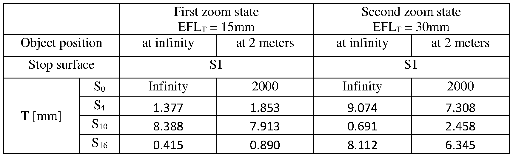


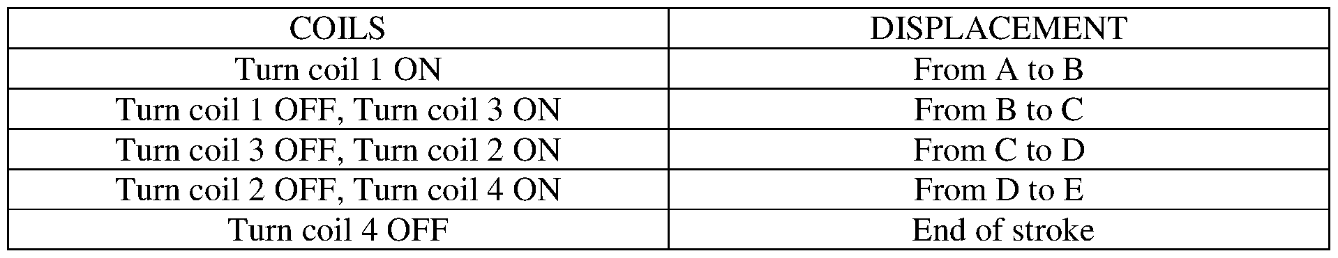
Claims
Priority Applications (10)
| Application Number | Priority Date | Filing Date | Title |
|---|---|---|---|
| CN202310987267.3A CN116990928A (en) | 2019-02-25 | 2020-02-19 | Camera and multiple camera comprising same |
| KR1020237039764A KR102655458B1 (en) | 2019-02-25 | 2020-02-19 | Multi-aperture cameras with at least one two state zoom camera |
| JP2021538717A JP2022508453A (en) | 2019-02-25 | 2020-02-19 | Multi-aperture camera with at least one camera with two zoom states |
| KR1020217025186A KR102424008B1 (en) | 2019-02-25 | 2020-02-19 | Multi-aperture camera with at least one two-state zoom camera |
| CN202310990981.8A CN117008281A (en) | 2019-02-25 | 2020-02-19 | Folding camera module |
| KR1020227024832A KR102606345B1 (en) | 2019-02-25 | 2020-02-19 | Multi-aperture cameras with at least one two state zoom camera |
| KR1020247011030A KR20240046652A (en) | 2019-02-25 | 2020-02-19 | Multi-aperture cameras with at least one two state zoom camera |
| CN202310986734.0A CN116990927A (en) | 2019-02-25 | 2020-02-19 | Folding camera module |
| US17/293,914 US11310405B2 (en) | 2019-02-25 | 2020-02-19 | Multi-aperture cameras with at least one two state zoom camera |
| CN202080006334.3A CN113167986B (en) | 2019-02-25 | 2020-02-19 | Multi-aperture camera with at least one two-state zoom camera |
Applications Claiming Priority (2)
| Application Number | Priority Date | Filing Date | Title |
|---|---|---|---|
| US201962809871P | 2019-02-25 | 2019-02-25 | |
| US62/809,871 | 2019-02-25 |
Publications (2)
| Publication Number | Publication Date |
|---|---|
| WO2020174325A2 true WO2020174325A2 (en) | 2020-09-03 |
| WO2020174325A3 WO2020174325A3 (en) | 2021-04-22 |
Family
ID=72239258
Family Applications (1)
| Application Number | Title | Priority Date | Filing Date |
|---|---|---|---|
| PCT/IB2020/051405 WO2020174325A2 (en) | 2019-02-25 | 2020-02-19 | Multi-aperture cameras with at least one two state zoom camera |
Country Status (6)
| Country | Link |
|---|---|
| US (1) | US11310405B2 (en) |
| JP (1) | JP2022508453A (en) |
| KR (4) | KR20240046652A (en) |
| CN (4) | CN117008281A (en) |
| TW (3) | TWI807555B (en) |
| WO (1) | WO2020174325A2 (en) |
Cited By (7)
| Publication number | Priority date | Publication date | Assignee | Title |
|---|---|---|---|---|
| EP3796064A1 (en) * | 2019-09-10 | 2021-03-24 | Jahwa Electronics Co., Ltd. | Camera actuator and compact camera including same |
| WO2022023914A1 (en) | 2020-07-31 | 2022-02-03 | Corephotonics Ltd. | Hall sensor - magnet geometry for large stroke linear position sensing |
| CN114253046A (en) * | 2020-09-24 | 2022-03-29 | 苹果公司 | Folded camera with auto-focus and optical image stabilization system |
| WO2022118176A1 (en) * | 2020-12-01 | 2022-06-09 | Corephotonics Ltd. | Folded camera with continuously adaptive zoom factor |
| WO2022157730A1 (en) * | 2021-01-25 | 2022-07-28 | Corephotonics Ltd. | Slim pop-out wide camera lenses |
| EP4152068A1 (en) * | 2021-09-17 | 2023-03-22 | Largan Digital Co., Ltd. | Imaging lens driving module and electronic device |
| EP4231077A4 (en) * | 2020-11-13 | 2024-04-10 | Huawei Tech Co Ltd | Voice coil motor, camera module, and electronic device |
Families Citing this family (10)
| Publication number | Priority date | Publication date | Assignee | Title |
|---|---|---|---|---|
| CN107748432A (en) | 2013-07-04 | 2018-03-02 | 核心光电有限公司 | Small-sized focal length lens external member |
| US9857568B2 (en) | 2013-07-04 | 2018-01-02 | Corephotonics Ltd. | Miniature telephoto lens assembly |
| US9392188B2 (en) | 2014-08-10 | 2016-07-12 | Corephotonics Ltd. | Zoom dual-aperture camera with folded lens |
| CN114615399A (en) | 2019-01-03 | 2022-06-10 | 核心光电有限公司 | Dual camera |
| CN111830669A (en) * | 2019-04-17 | 2020-10-27 | 浙江舜宇光学有限公司 | Electronic imaging device |
| US11656538B2 (en) | 2019-11-25 | 2023-05-23 | Corephotonics Ltd. | Folded zoom camera module with adaptive aperture |
| EP4191332A1 (en) | 2020-05-30 | 2023-06-07 | Corephotonics Ltd. | Systems and methods for obtaining a super macro image |
| US11886036B2 (en) | 2021-01-25 | 2024-01-30 | Hand Held Products, Inc. | Variable focus assemblies and apparatuses having crossed bearing balls |
| KR102609144B1 (en) * | 2021-09-03 | 2023-12-05 | 삼성전기주식회사 | Camera Module |
| US20230288684A1 (en) * | 2022-03-11 | 2023-09-14 | Hand Held Products, Inc. | Variable focusing lens apparatus |
Family Cites Families (155)
| Publication number | Priority date | Publication date | Assignee | Title |
|---|---|---|---|---|
| US2106752A (en) | 1934-12-03 | 1938-02-01 | Sheet Polarizer Company Inc | Field divider |
| US2354503A (en) | 1941-12-01 | 1944-07-25 | Taylor Taylor & Hobson Ltd | Optical objective of the telephoto type |
| US2378170A (en) | 1943-06-25 | 1945-06-12 | Eastman Kodak Co | Telephoto lens |
| US2441093A (en) | 1946-07-22 | 1948-05-04 | Eastman Kodak Co | Telephoto lens |
| US3388956A (en) | 1963-04-10 | 1968-06-18 | Voigtlaender Ag | Photographic telephoto lenses of high telephoto power |
| DE1447278A1 (en) | 1964-06-20 | 1968-12-19 | Voigtlaender Ag | Tele-anastigmat of medium light intensity with a large telephoto effect |
| US3558218A (en) | 1967-12-01 | 1971-01-26 | Polaroid Corp | Three-element telephoto objective lens |
| JPS5116135B2 (en) | 1972-05-10 | 1976-05-21 | ||
| US3942876A (en) | 1972-09-07 | 1976-03-09 | Ponder & Best, Inc. | Telephoto lens |
| JPS5327421A (en) | 1976-08-26 | 1978-03-14 | Asahi Optical Co Ltd | Small telephotographic lens |
| JPS55163510A (en) | 1979-06-06 | 1980-12-19 | Nippon Kogaku Kk <Nikon> | Telephoto lens |
| JPS5740220A (en) * | 1980-08-22 | 1982-03-05 | Nippon Kogaku Kk <Nikon> | Zoom lens composed of 3 groups |
| JPS5850509A (en) | 1981-09-21 | 1983-03-25 | Ricoh Co Ltd | Small-sized telephoto lens |
| US5000551A (en) | 1989-06-05 | 1991-03-19 | Nikon Corporation | Zoom lens |
| JP3245452B2 (en) * | 1991-07-24 | 2002-01-15 | オリンパス光学工業株式会社 | Small three-group zoom lens |
| JP3358639B2 (en) * | 1994-05-31 | 2002-12-24 | 京セラ株式会社 | Camera focus control method |
| JP3676524B2 (en) | 1996-10-25 | 2005-07-27 | ペンタックス株式会社 | prism |
| JPH1195105A (en) * | 1997-07-22 | 1999-04-09 | Nikon Corp | Focusing system for variable power optical system |
| JPH11223771A (en) * | 1998-02-06 | 1999-08-17 | Nikon Corp | Vari-focal lens system |
| US6147702A (en) | 1998-04-17 | 2000-11-14 | Intel Corporation | Calibration of digital cameras |
| US6195209B1 (en) | 1999-05-04 | 2001-02-27 | U.S. Precision Lens Incorporated | Projection lenses having reduced lateral color for use with pixelized panels |
| JP4278879B2 (en) | 2001-02-27 | 2009-06-17 | 株式会社オートネットワーク技術研究所 | Vehicle periphery visual recognition device |
| JP2003057546A (en) * | 2001-08-20 | 2003-02-26 | Pentax Corp | Zoom lens system |
| JP3503941B2 (en) | 2002-02-04 | 2004-03-08 | 富士写真光機株式会社 | 3-group zoom lens |
| JP4262439B2 (en) * | 2002-05-14 | 2009-05-13 | オリンパス株式会社 | Zoom lens and electronic imaging apparatus having the same |
| JP2004334185A (en) * | 2003-04-18 | 2004-11-25 | Canon Inc | Zoom lens |
| US6924948B2 (en) | 2003-08-21 | 2005-08-02 | Arc Design, Inc. | Multifocal lens system for digital cameras |
| JP4276914B2 (en) | 2003-09-18 | 2009-06-10 | オリンパス株式会社 | Vibration wave linear motor and driving method thereof |
| JP2005134486A (en) | 2003-10-28 | 2005-05-26 | Ricoh Co Ltd | Color image reading lens, color image reading lens unit, color image reader and image forming apparatus |
| JP2005173191A (en) | 2003-12-11 | 2005-06-30 | Olympus Corp | Optical path bending optical system |
| JP2005215473A (en) | 2004-01-30 | 2005-08-11 | Sekinosu Kk | Projection lens device |
| US6980379B1 (en) | 2004-07-19 | 2005-12-27 | Microalign Technologies, Inc. | Flat wide-angle objective |
| JP4684597B2 (en) | 2004-08-13 | 2011-05-18 | Hoya株式会社 | Lens control device |
| JP4652007B2 (en) * | 2004-09-30 | 2011-03-16 | 日本電産コパル株式会社 | Lens drive device |
| US9155483B2 (en) | 2004-12-03 | 2015-10-13 | The Invention Science Fund I, Llc | Vision modification with reflected image |
| US7206136B2 (en) | 2005-02-18 | 2007-04-17 | Eastman Kodak Company | Digital camera using multiple lenses and image sensors to provide an extended zoom range |
| JP4794912B2 (en) | 2005-06-02 | 2011-10-19 | キヤノン株式会社 | Zoom lens and imaging apparatus having the same |
| JP2007025641A (en) * | 2005-06-17 | 2007-02-01 | Matsushita Electric Ind Co Ltd | Zoom lens system and lens barrel equipped with the same |
| JP2007164065A (en) * | 2005-12-16 | 2007-06-28 | Konica Minolta Opto Inc | Lens unit and imaging apparatus |
| JP2007219199A (en) * | 2006-02-17 | 2007-08-30 | Konica Minolta Opto Inc | Lens unit, imaging device and manufacturing method of lens |
| JP2007219409A (en) * | 2006-02-20 | 2007-08-30 | Mitsubishi Electric Corp | Lens unit and manufacturing method therefor |
| JP4905653B2 (en) | 2006-03-28 | 2012-03-28 | ペンタックスリコーイメージング株式会社 | Medium telephoto lens system |
| CN101056360A (en) * | 2006-04-13 | 2007-10-17 | 普立尔科技股份有限公司 | Zooming camera module of the hand-held action device |
| KR100900486B1 (en) | 2006-09-04 | 2009-06-03 | 삼성테크윈 주식회사 | Optical module for photographing device and photographing device comprising the same |
| JP4956343B2 (en) | 2006-09-25 | 2012-06-20 | 富士フイルム株式会社 | Bifocal imaging optical system and imaging device |
| JP2008102427A (en) * | 2006-10-20 | 2008-05-01 | Tamron Co Ltd | Optical apparatus and imaging apparatus |
| TWI332584B (en) | 2007-04-25 | 2010-11-01 | Largan Precision Co Ltd | Optical lens system for taking image |
| US7918398B2 (en) | 2007-06-04 | 2011-04-05 | Hand Held Products, Inc. | Indicia reading terminal having multiple setting imaging lens |
| JP2008304708A (en) | 2007-06-07 | 2008-12-18 | Konica Minolta Opto Inc | Zoom lens and imaging apparatus |
| TWI351530B (en) | 2007-07-05 | 2011-11-01 | Largan Precision Co Ltd | Inverse telephoto with correction lenses |
| TWI354820B (en) | 2007-08-14 | 2011-12-21 | Largan Precision Co Ltd | Optical lens system for taking image |
| JP4947423B2 (en) | 2007-08-29 | 2012-06-06 | コニカミノルタオプト株式会社 | Imaging lens |
| US7710665B2 (en) | 2007-11-08 | 2010-05-04 | Samsung Electro-Mechanics Co., Ltd. | Imaging optical system |
| TWI361914B (en) | 2007-11-16 | 2012-04-11 | Largan Precision Co Ltd | Optical lens system for taking image |
| JP2009134175A (en) | 2007-11-30 | 2009-06-18 | Olympus Imaging Corp | Image forming optical system |
| CN101821658B (en) | 2007-12-04 | 2014-02-26 | 黑眼睛光学有限公司 | Zoom lens and camera system |
| TWI354821B (en) | 2007-12-18 | 2011-12-21 | Largan Precision Co Ltd | Optical lens system for taking image |
| US8184380B2 (en) | 2007-12-28 | 2012-05-22 | Panasonic Corporation | Lens barrel |
| TWI361915B (en) | 2008-02-18 | 2012-04-11 | Largan Precision Co Ltd | Optical lens system for taking image |
| TWI361913B (en) | 2008-02-27 | 2012-04-11 | Largan Precision Co Ltd | Optical lens system for taking image |
| TWI361903B (en) | 2008-02-27 | 2012-04-11 | Largan Precision Co Ltd | Optical lens system for taking image |
| JP2009216941A (en) | 2008-03-10 | 2009-09-24 | Tamron Co Ltd | Bending variable power optical system |
| JP2009258286A (en) | 2008-04-15 | 2009-11-05 | Konica Minolta Opto Inc | Imaging lens, imaging unit, and mobile terminal |
| TWI395992B (en) | 2008-07-25 | 2013-05-11 | Largan Precision Co | Four-piece optical lens system for taking image |
| JP5304117B2 (en) | 2008-09-05 | 2013-10-02 | コニカミノルタ株式会社 | Imaging lens, imaging device, and portable terminal |
| US8049979B2 (en) * | 2008-09-08 | 2011-11-01 | Panasonic Corporation | Lens barrel and imaging device |
| TWI384254B (en) | 2008-10-16 | 2013-02-01 | Largan Precision Co Ltd | Optical lens system for taking image |
| TWI379102B (en) | 2008-11-20 | 2012-12-11 | Largan Precision Co Ltd | Optical lens system for taking image |
| TWI388878B (en) | 2008-12-01 | 2013-03-11 | Largan Precision Co Ltd | Optical lens system for taking image |
| TWI382199B (en) | 2008-12-16 | 2013-01-11 | Largan Precision Co Ltd | Optical lens system for taking image |
| JP5300467B2 (en) | 2008-12-26 | 2013-09-25 | キヤノン株式会社 | Optical system and optical apparatus having the same |
| US7826149B2 (en) | 2008-12-27 | 2010-11-02 | Largan Precision Co., Ltd. | Optical lens system for taking image |
| JP2010164841A (en) * | 2009-01-16 | 2010-07-29 | Sharp Corp | Imaging module, image capturing apparatus and optical equipment |
| TWI394979B (en) | 2009-01-22 | 2013-05-01 | Largan Precision Co Ltd | Photographing optical lens assembly |
| TWI406004B (en) | 2009-02-19 | 2013-08-21 | Largan Precision Co Ltd | Imaging optical lens assembly |
| TWI406005B (en) | 2009-02-24 | 2013-08-21 | Asia Optical Co Inc | Small-sized zoom lens and image pickup device with the same |
| JP2010277067A (en) * | 2009-04-28 | 2010-12-09 | Mitsumi Electric Co Ltd | Lens driving device |
| TWI395990B (en) | 2009-05-11 | 2013-05-11 | Largan Precision Co Ltd | Optical lens system for taking image |
| TWI404972B (en) | 2009-06-19 | 2013-08-11 | Largan Precision Co | Optical lens system for taking image |
| TWI401466B (en) | 2009-06-19 | 2013-07-11 | Largan Precision Co | Optical lens system for taking image |
| KR20110002630A (en) | 2009-07-02 | 2011-01-10 | 삼성전자주식회사 | Operation method for camera of portable device and apparatus using the same |
| TWI421557B (en) | 2009-07-14 | 2014-01-01 | Largan Precision Co Ltd | Imaging lens system |
| DE102009028861B4 (en) | 2009-08-25 | 2015-03-05 | Trimble Jena Gmbh | Measuring device with reduced amount of stray light and manufacturing method for this |
| US8559118B2 (en) | 2009-11-18 | 2013-10-15 | DigitalOptics Corporation Europe Limited | Fixed focal length optical lens architecture providing a customized depth of focus optical system |
| JP2011128445A (en) | 2009-12-18 | 2011-06-30 | Sony Corp | Zoom lens and image pickup apparatus |
| JP2011138047A (en) | 2009-12-28 | 2011-07-14 | Olympus Imaging Corp | Image pickup apparatus having optical path reflecting zoom lens |
| JP2011141396A (en) | 2010-01-06 | 2011-07-21 | Tamron Co Ltd | Imaging lens, camera module, and imaging apparatus |
| TWI406027B (en) | 2010-04-08 | 2013-08-21 | Largan Precision Co Ltd | Imaging lens assembly |
| JP5498259B2 (en) | 2010-05-24 | 2014-05-21 | 株式会社タムロン | High magnification zoom lens |
| TWI401485B (en) | 2010-06-10 | 2013-07-11 | Largan Precision Co Ltd | Imaging optical lens assembly |
| TWI434096B (en) | 2010-09-16 | 2014-04-11 | Largan Precision Co Ltd | Optical imaging lens system |
| JP2012068510A (en) | 2010-09-24 | 2012-04-05 | Hoya Corp | Photographic optical system and photographic device |
| US20120075518A1 (en) | 2010-09-29 | 2012-03-29 | Hoya Corporation | Imaging unit |
| TWI435135B (en) | 2010-10-06 | 2014-04-21 | Largan Precision Co Ltd | Optical lens system |
| US8339714B2 (en) | 2010-10-13 | 2012-12-25 | Olympus Imaging Corp. | Zoom lens and imaging apparatus incorporating the same |
| JP5804878B2 (en) | 2010-11-01 | 2015-11-04 | キヤノン株式会社 | Zoom lens and imaging apparatus having the same |
| TWI418877B (en) | 2010-12-15 | 2013-12-11 | Largan Precision Co | Imagery optical system |
| JP5802401B2 (en) | 2011-02-22 | 2015-10-28 | オリンパス株式会社 | Lens frame and lens assembly |
| US8976466B2 (en) | 2011-03-11 | 2015-03-10 | Olympus Corporation | Imaging optical system and imaging apparatus using the same |
| TWI429979B (en) | 2011-04-13 | 2014-03-11 | Largan Precision Co Ltd | Optical image lens assembly |
| KR101224790B1 (en) * | 2011-06-14 | 2013-01-21 | 삼성전기주식회사 | Image Photographing Device |
| WO2013014850A1 (en) | 2011-07-25 | 2013-01-31 | 富士フイルム株式会社 | Imaging lens and imaging device provided with imaging lens |
| KR20130025137A (en) | 2011-09-01 | 2013-03-11 | 삼성전자주식회사 | Panoramic imaging lens and panoramic imaging system using the same |
| KR101301314B1 (en) | 2011-10-10 | 2013-08-29 | 삼성전기주식회사 | Image Lense Unit |
| JP5809936B2 (en) * | 2011-11-08 | 2015-11-11 | オリンパス株式会社 | Imaging device |
| CN103105660A (en) * | 2011-11-09 | 2013-05-15 | 华晶科技股份有限公司 | Lens actuating device and lens actuating method thereof |
| KR101932717B1 (en) | 2012-02-13 | 2018-12-26 | 삼성전자주식회사 | Imaging lens system |
| KR101964297B1 (en) | 2012-02-16 | 2019-04-01 | 엘지이노텍 주식회사 | Imaging lens |
| TWI460465B (en) | 2012-04-20 | 2014-11-11 | Largan Precision Co Ltd | Optical image lens system |
| JP2013238848A (en) | 2012-04-20 | 2013-11-28 | Hoya Corp | Imaging apparatus |
| KR101422910B1 (en) | 2012-04-30 | 2014-07-23 | 삼성전기주식회사 | Optical system for camera |
| KR101941248B1 (en) | 2012-07-23 | 2019-04-10 | 삼성전자주식회사 | Zoom lens and imaging apparatus employing the same |
| JP5808311B2 (en) | 2012-11-28 | 2015-11-10 | キヤノン株式会社 | Zoom lens and imaging apparatus having the same |
| KR101452084B1 (en) | 2013-01-22 | 2014-10-16 | 삼성전기주식회사 | Subminiature optical system and portable device having the same |
| TWI476435B (en) | 2013-03-20 | 2015-03-11 | Largan Precision Co Ltd | Imaging lens assembly |
| CN205281004U (en) | 2013-03-25 | 2016-06-01 | 富士胶片株式会社 | Pick -up lens and image pick -up device equipped with same |
| JP2014209163A (en) | 2013-03-29 | 2014-11-06 | 富士フイルム株式会社 | Imaging lens and imaging apparatus including the same |
| JP5886230B2 (en) | 2013-03-29 | 2016-03-16 | 富士フイルム株式会社 | Imaging lens and imaging device provided with imaging lens |
| JP6000179B2 (en) | 2013-03-29 | 2016-09-28 | 富士フイルム株式会社 | Imaging lens and imaging device provided with imaging lens |
| TWI461779B (en) | 2013-04-25 | 2014-11-21 | Largan Precision Co Ltd | Imaging lens assembly |
| JP6100089B2 (en) | 2013-05-17 | 2017-03-22 | キヤノン株式会社 | Image processing apparatus, image processing method, and program |
| JP6136588B2 (en) | 2013-05-31 | 2017-05-31 | ソニー株式会社 | Zoom lens and imaging device |
| US10168882B2 (en) | 2013-06-09 | 2019-01-01 | Apple Inc. | Device, method, and graphical user interface for switching between camera interfaces |
| JP6139713B2 (en) | 2013-06-13 | 2017-05-31 | コアフォトニクス リミテッド | Dual aperture zoom digital camera |
| CN107748432A (en) | 2013-07-04 | 2018-03-02 | 核心光电有限公司 | Small-sized focal length lens external member |
| CN105830425A (en) * | 2013-10-18 | 2016-08-03 | 泽莱特科股份有限公司 | Methods and apparatus for capturing and/or combining images |
| US9223118B2 (en) | 2013-10-31 | 2015-12-29 | Apple Inc. | Small form factor telephoto camera |
| CN103698876B (en) * | 2013-12-17 | 2016-02-03 | 中山联合光电科技有限公司 | A kind of mobile lens |
| US9316810B2 (en) | 2014-03-07 | 2016-04-19 | Apple Inc. | Folded telephoto camera lens system |
| US9557627B2 (en) | 2014-03-07 | 2017-01-31 | Apple Inc. | Folded camera lens systems |
| US9383550B2 (en) | 2014-04-04 | 2016-07-05 | Qualcomm Incorporated | Auto-focus in low-profile folded optics multi-camera system |
| US9386222B2 (en) | 2014-06-20 | 2016-07-05 | Qualcomm Incorporated | Multi-camera system using folded optics free from parallax artifacts |
| US9549107B2 (en) | 2014-06-20 | 2017-01-17 | Qualcomm Incorporated | Autofocus for folded optic array cameras |
| US9392188B2 (en) * | 2014-08-10 | 2016-07-12 | Corephotonics Ltd. | Zoom dual-aperture camera with folded lens |
| TWI518360B (en) | 2014-08-26 | 2016-01-21 | 大立光電股份有限公司 | Image capturing optical system, image capturing device and electronic device |
| JP2016057468A (en) | 2014-09-10 | 2016-04-21 | Hoya株式会社 | Bending imaging device |
| KR101544792B1 (en) | 2014-12-30 | 2015-08-18 | 주식회사 세코닉스 | Iris lens system |
| EP3492958B1 (en) * | 2015-04-02 | 2022-03-30 | Corephotonics Ltd. | Dual voice coil motor structure in a dual-optical module camera |
| EP3540492B1 (en) * | 2015-04-16 | 2021-12-15 | Corephotonics Ltd. | Auto focus and optical image stabilization in a compact folded camera |
| JP6401103B2 (en) | 2015-04-20 | 2018-10-03 | 富士フイルム株式会社 | Endoscope objective lens and endoscope |
| US9817213B2 (en) | 2015-04-23 | 2017-11-14 | Apple Inc. | Camera lens system with five lens components |
| TWI585485B (en) | 2015-05-19 | 2017-06-01 | 先進光電科技股份有限公司 | Optical image capturing system |
| KR101992040B1 (en) * | 2015-06-24 | 2019-06-21 | 코어포토닉스 리미티드 | Low-Profile 3-Axis Actuator for Foldable Lens Cameras |
| KR102494776B1 (en) | 2015-08-04 | 2023-02-02 | 엘지이노텍 주식회사 | Image pickup lens |
| KR101993077B1 (en) | 2015-09-06 | 2019-06-25 | 코어포토닉스 리미티드 | Automatic focus and optical image stabilization by roll compensation of compact folding camera |
| KR101813329B1 (en) | 2015-10-13 | 2017-12-28 | 삼성전기주식회사 | Optical Imaging System |
| US10185123B2 (en) | 2015-10-22 | 2019-01-22 | Apple Inc. | Lens system |
| KR102570101B1 (en) | 2015-12-04 | 2023-08-23 | 삼성전자주식회사 | Lens assembly and electronic device including the same |
| CN110426825B (en) * | 2016-05-10 | 2022-11-25 | 台湾东电化股份有限公司 | Lens system |
| CN106526788B (en) | 2016-08-25 | 2020-05-01 | 玉晶光电(厦门)有限公司 | Optical imaging lens |
| KR20180032058A (en) * | 2016-09-21 | 2018-03-29 | 삼성전자주식회사 | Optical lens assembly and electronic apparatus having the same |
| CN113805406A (en) * | 2017-01-12 | 2021-12-17 | 核心光电有限公司 | Compact folding camera and method of assembling the same |
| IL302577A (en) * | 2017-02-23 | 2023-07-01 | Corephotonics Ltd | Folded camera lens designs |
| EP4357832A2 (en) * | 2017-03-15 | 2024-04-24 | Corephotonics Ltd. | Camera with panoramic scanning range |
| KR20210029781A (en) * | 2018-07-11 | 2021-03-16 | 키옵티크 포토닉스 게엠베하 운트 콤파니 카게 | How to operate focus and zoom objectives and focus and zoom objectives |
-
2020
- 2020-02-19 KR KR1020247011030A patent/KR20240046652A/en active IP Right Grant
- 2020-02-19 US US17/293,914 patent/US11310405B2/en active Active
- 2020-02-19 CN CN202310990981.8A patent/CN117008281A/en active Pending
- 2020-02-19 CN CN202310986734.0A patent/CN116990927A/en active Pending
- 2020-02-19 KR KR1020237039764A patent/KR102655458B1/en active IP Right Grant
- 2020-02-19 CN CN202310987267.3A patent/CN116990928A/en active Pending
- 2020-02-19 JP JP2021538717A patent/JP2022508453A/en active Pending
- 2020-02-19 KR KR1020227024832A patent/KR102606345B1/en active IP Right Grant
- 2020-02-19 KR KR1020217025186A patent/KR102424008B1/en active IP Right Grant
- 2020-02-19 CN CN202080006334.3A patent/CN113167986B/en active Active
- 2020-02-19 WO PCT/IB2020/051405 patent/WO2020174325A2/en active Application Filing
- 2020-02-21 TW TW110148688A patent/TWI807555B/en active
- 2020-02-21 TW TW112119689A patent/TW202340788A/en unknown
- 2020-02-21 TW TW109105769A patent/TWI754229B/en active
Cited By (13)
| Publication number | Priority date | Publication date | Assignee | Title |
|---|---|---|---|---|
| EP3796064A1 (en) * | 2019-09-10 | 2021-03-24 | Jahwa Electronics Co., Ltd. | Camera actuator and compact camera including same |
| US11163133B2 (en) | 2019-09-10 | 2021-11-02 | Jahwa Electronics Co., Ltd. | Camera actuator and compact camera including same |
| WO2022023914A1 (en) | 2020-07-31 | 2022-02-03 | Corephotonics Ltd. | Hall sensor - magnet geometry for large stroke linear position sensing |
| CN114253046A (en) * | 2020-09-24 | 2022-03-29 | 苹果公司 | Folded camera with auto-focus and optical image stabilization system |
| EP4231077A4 (en) * | 2020-11-13 | 2024-04-10 | Huawei Tech Co Ltd | Voice coil motor, camera module, and electronic device |
| CN114868065A (en) * | 2020-12-01 | 2022-08-05 | 核心光电有限公司 | Folding camera with continuously adaptive zoom factor |
| EP4066036A4 (en) * | 2020-12-01 | 2023-01-25 | Corephotonics Ltd. | Folded camera with continuously adaptive zoom factor |
| US20230039197A1 (en) * | 2020-12-01 | 2023-02-09 | Corephotonics Ltd. | Folded camera with continuously adaptive zoom factor |
| US11803106B2 (en) * | 2020-12-01 | 2023-10-31 | Corephotonics Ltd. | Folded camera with continuously adaptive zoom factor |
| WO2022118176A1 (en) * | 2020-12-01 | 2022-06-09 | Corephotonics Ltd. | Folded camera with continuously adaptive zoom factor |
| WO2022157730A1 (en) * | 2021-01-25 | 2022-07-28 | Corephotonics Ltd. | Slim pop-out wide camera lenses |
| US11930263B2 (en) | 2021-01-25 | 2024-03-12 | Corephotonics Ltd. | Slim pop-out wide camera lenses |
| EP4152068A1 (en) * | 2021-09-17 | 2023-03-22 | Largan Digital Co., Ltd. | Imaging lens driving module and electronic device |
Also Published As
| Publication number | Publication date |
|---|---|
| US20220046151A1 (en) | 2022-02-10 |
| TW202340788A (en) | 2023-10-16 |
| TWI807555B (en) | 2023-07-01 |
| KR102606345B1 (en) | 2023-11-23 |
| CN117008281A (en) | 2023-11-07 |
| KR102424008B1 (en) | 2022-07-22 |
| KR20210113318A (en) | 2021-09-15 |
| KR20230162997A (en) | 2023-11-29 |
| KR20220107312A (en) | 2022-08-02 |
| CN113167986A (en) | 2021-07-23 |
| TW202034016A (en) | 2020-09-16 |
| US11310405B2 (en) | 2022-04-19 |
| JP2022508453A (en) | 2022-01-19 |
| TW202215098A (en) | 2022-04-16 |
| TWI754229B (en) | 2022-02-01 |
| CN113167986B (en) | 2023-09-01 |
| KR102655458B1 (en) | 2024-04-08 |
| KR20240046652A (en) | 2024-04-09 |
| WO2020174325A3 (en) | 2021-04-22 |
| CN116990927A (en) | 2023-11-03 |
| CN116990928A (en) | 2023-11-03 |
Similar Documents
| Publication | Publication Date | Title |
|---|---|---|
| KR102606345B1 (en) | Multi-aperture cameras with at least one two state zoom camera | |
| JP7252247B2 (en) | Multi-aperture camera comprising at least one camera with two zoom states | |
| JP2024060620A (en) | Multi-aperture camera with at least one camera having two zoom states | |
| WO2022118176A1 (en) | Folded camera with continuously adaptive zoom factor |
Legal Events
| Date | Code | Title | Description |
|---|---|---|---|
| 121 | Ep: the epo has been informed by wipo that ep was designated in this application |
Ref document number: 20763096 Country of ref document: EP Kind code of ref document: A2 |
|
| ENP | Entry into the national phase |
Ref document number: 2021538717 Country of ref document: JP Kind code of ref document: A |
|
| ENP | Entry into the national phase |
Ref document number: 20217025186 Country of ref document: KR Kind code of ref document: A |
|
| NENP | Non-entry into the national phase |
Ref country code: DE |
|
| 122 | Ep: pct application non-entry in european phase |
Ref document number: 20763096 Country of ref document: EP Kind code of ref document: A2 |