WO2020170828A1 - 防食方法および防食装置 - Google Patents
防食方法および防食装置 Download PDFInfo
- Publication number
- WO2020170828A1 WO2020170828A1 PCT/JP2020/004447 JP2020004447W WO2020170828A1 WO 2020170828 A1 WO2020170828 A1 WO 2020170828A1 JP 2020004447 W JP2020004447 W JP 2020004447W WO 2020170828 A1 WO2020170828 A1 WO 2020170828A1
- Authority
- WO
- WIPO (PCT)
- Prior art keywords
- solution
- concrete
- anticorrosion
- rebar
- drainage
- Prior art date
- Legal status (The legal status is an assumption and is not a legal conclusion. Google has not performed a legal analysis and makes no representation as to the accuracy of the status listed.)
- Ceased
Links
Images




Classifications
-
- C—CHEMISTRY; METALLURGY
- C04—CEMENTS; CONCRETE; ARTIFICIAL STONE; CERAMICS; REFRACTORIES
- C04B—LIME, MAGNESIA; SLAG; CEMENTS; COMPOSITIONS THEREOF, e.g. MORTARS, CONCRETE OR LIKE BUILDING MATERIALS; ARTIFICIAL STONE; CERAMICS; REFRACTORIES; TREATMENT OF NATURAL STONE
- C04B41/00—After-treatment of mortars, concrete, artificial stone or ceramics; Treatment of natural stone
- C04B41/60—After-treatment of mortars, concrete, artificial stone or ceramics; Treatment of natural stone of only artificial stone
- C04B41/61—Coating or impregnation
- C04B41/65—Coating or impregnation with inorganic materials
-
- B—PERFORMING OPERATIONS; TRANSPORTING
- B05—SPRAYING OR ATOMISING IN GENERAL; APPLYING FLUENT MATERIALS TO SURFACES, IN GENERAL
- B05C—APPARATUS FOR APPLYING FLUENT MATERIALS TO SURFACES, IN GENERAL
- B05C3/00—Apparatus in which the work is brought into contact with a bulk quantity of liquid or other fluent material
- B05C3/02—Apparatus in which the work is brought into contact with a bulk quantity of liquid or other fluent material the work being immersed in the liquid or other fluent material
-
- B—PERFORMING OPERATIONS; TRANSPORTING
- B05—SPRAYING OR ATOMISING IN GENERAL; APPLYING FLUENT MATERIALS TO SURFACES, IN GENERAL
- B05D—PROCESSES FOR APPLYING FLUENT MATERIALS TO SURFACES, IN GENERAL
- B05D1/00—Processes for applying liquids or other fluent materials
- B05D1/18—Processes for applying liquids or other fluent materials performed by dipping
-
- C—CHEMISTRY; METALLURGY
- C04—CEMENTS; CONCRETE; ARTIFICIAL STONE; CERAMICS; REFRACTORIES
- C04B—LIME, MAGNESIA; SLAG; CEMENTS; COMPOSITIONS THEREOF, e.g. MORTARS, CONCRETE OR LIKE BUILDING MATERIALS; ARTIFICIAL STONE; CERAMICS; REFRACTORIES; TREATMENT OF NATURAL STONE
- C04B14/00—Use of inorganic materials as fillers, e.g. pigments, for mortars, concrete or artificial stone; Treatment of inorganic materials specially adapted to enhance their filling properties in mortars, concrete or artificial stone
- C04B14/38—Fibrous materials; Whiskers
- C04B14/48—Metal
-
- C—CHEMISTRY; METALLURGY
- C04—CEMENTS; CONCRETE; ARTIFICIAL STONE; CERAMICS; REFRACTORIES
- C04B—LIME, MAGNESIA; SLAG; CEMENTS; COMPOSITIONS THEREOF, e.g. MORTARS, CONCRETE OR LIKE BUILDING MATERIALS; ARTIFICIAL STONE; CERAMICS; REFRACTORIES; TREATMENT OF NATURAL STONE
- C04B41/00—After-treatment of mortars, concrete, artificial stone or ceramics; Treatment of natural stone
- C04B41/009—After-treatment of mortars, concrete, artificial stone or ceramics; Treatment of natural stone characterised by the material treated
-
- C—CHEMISTRY; METALLURGY
- C04—CEMENTS; CONCRETE; ARTIFICIAL STONE; CERAMICS; REFRACTORIES
- C04B—LIME, MAGNESIA; SLAG; CEMENTS; COMPOSITIONS THEREOF, e.g. MORTARS, CONCRETE OR LIKE BUILDING MATERIALS; ARTIFICIAL STONE; CERAMICS; REFRACTORIES; TREATMENT OF NATURAL STONE
- C04B41/00—After-treatment of mortars, concrete, artificial stone or ceramics; Treatment of natural stone
- C04B41/45—Coating or impregnating, e.g. injection in masonry, partial coating of green or fired ceramics, organic coating compositions for adhering together two concrete elements
- C04B41/4505—Coating or impregnating, e.g. injection in masonry, partial coating of green or fired ceramics, organic coating compositions for adhering together two concrete elements characterised by the method of application
- C04B41/4535—Coating or impregnating, e.g. injection in masonry, partial coating of green or fired ceramics, organic coating compositions for adhering together two concrete elements characterised by the method of application applied as a solution, emulsion, dispersion or suspension
-
- C—CHEMISTRY; METALLURGY
- C04—CEMENTS; CONCRETE; ARTIFICIAL STONE; CERAMICS; REFRACTORIES
- C04B—LIME, MAGNESIA; SLAG; CEMENTS; COMPOSITIONS THEREOF, e.g. MORTARS, CONCRETE OR LIKE BUILDING MATERIALS; ARTIFICIAL STONE; CERAMICS; REFRACTORIES; TREATMENT OF NATURAL STONE
- C04B41/00—After-treatment of mortars, concrete, artificial stone or ceramics; Treatment of natural stone
- C04B41/45—Coating or impregnating, e.g. injection in masonry, partial coating of green or fired ceramics, organic coating compositions for adhering together two concrete elements
- C04B41/50—Coating or impregnating, e.g. injection in masonry, partial coating of green or fired ceramics, organic coating compositions for adhering together two concrete elements with inorganic materials
- C04B41/5007—Coating or impregnating, e.g. injection in masonry, partial coating of green or fired ceramics, organic coating compositions for adhering together two concrete elements with inorganic materials with salts or salty compositions, e.g. for salt glazing
-
- C—CHEMISTRY; METALLURGY
- C09—DYES; PAINTS; POLISHES; NATURAL RESINS; ADHESIVES; COMPOSITIONS NOT OTHERWISE PROVIDED FOR; APPLICATIONS OF MATERIALS NOT OTHERWISE PROVIDED FOR
- C09D—COATING COMPOSITIONS, e.g. PAINTS, VARNISHES OR LACQUERS; FILLING PASTES; CHEMICAL PAINT OR INK REMOVERS; INKS; CORRECTING FLUIDS; WOODSTAINS; PASTES OR SOLIDS FOR COLOURING OR PRINTING; USE OF MATERIALS THEREFOR
- C09D5/00—Coating compositions, e.g. paints, varnishes or lacquers, characterised by their physical nature or the effects produced; Filling pastes
- C09D5/08—Anti-corrosive paints
- C09D5/082—Anti-corrosive paints characterised by the anti-corrosive pigment
- C09D5/084—Inorganic compounds
-
- C—CHEMISTRY; METALLURGY
- C23—COATING METALLIC MATERIAL; COATING MATERIAL WITH METALLIC MATERIAL; CHEMICAL SURFACE TREATMENT; DIFFUSION TREATMENT OF METALLIC MATERIAL; COATING BY VACUUM EVAPORATION, BY SPUTTERING, BY ION IMPLANTATION OR BY CHEMICAL VAPOUR DEPOSITION, IN GENERAL; INHIBITING CORROSION OF METALLIC MATERIAL OR INCRUSTATION IN GENERAL
- C23C—COATING METALLIC MATERIAL; COATING MATERIAL WITH METALLIC MATERIAL; SURFACE TREATMENT OF METALLIC MATERIAL BY DIFFUSION INTO THE SURFACE, BY CHEMICAL CONVERSION OR SUBSTITUTION; COATING BY VACUUM EVAPORATION, BY SPUTTERING, BY ION IMPLANTATION OR BY CHEMICAL VAPOUR DEPOSITION, IN GENERAL
- C23C22/00—Chemical surface treatment of metallic material by reaction of the surface with a reactive liquid, leaving reaction products of surface material in the coating, e.g. conversion coatings, passivation of metals
- C23C22/05—Chemical surface treatment of metallic material by reaction of the surface with a reactive liquid, leaving reaction products of surface material in the coating, e.g. conversion coatings, passivation of metals using aqueous solutions
- C23C22/60—Chemical surface treatment of metallic material by reaction of the surface with a reactive liquid, leaving reaction products of surface material in the coating, e.g. conversion coatings, passivation of metals using aqueous solutions using alkaline aqueous solutions with pH greater than 8
- C23C22/62—Treatment of iron or alloys based thereon
-
- E—FIXED CONSTRUCTIONS
- E04—BUILDING
- E04C—STRUCTURAL ELEMENTS; BUILDING MATERIALS
- E04C5/00—Reinforcing elements, e.g. for concrete; Auxiliary elements therefor
- E04C5/01—Reinforcing elements of metal, e.g. with non-structural coatings
- E04C5/015—Anti-corrosion coatings or treating compositions, e.g. containing waterglass or based on another metal
-
- E—FIXED CONSTRUCTIONS
- E04—BUILDING
- E04G—SCAFFOLDING; FORMS; SHUTTERING; BUILDING IMPLEMENTS OR AIDS, OR THEIR USE; HANDLING BUILDING MATERIALS ON THE SITE; REPAIRING, BREAKING-UP OR OTHER WORK ON EXISTING BUILDINGS
- E04G23/00—Working measures on existing buildings
- E04G23/02—Repairing, e.g. filling cracks; Restoring; Altering; Enlarging
-
- G—PHYSICS
- G01—MEASURING; TESTING
- G01N—INVESTIGATING OR ANALYSING MATERIALS BY DETERMINING THEIR CHEMICAL OR PHYSICAL PROPERTIES
- G01N17/00—Investigating resistance of materials to the weather, to corrosion, or to light
-
- C—CHEMISTRY; METALLURGY
- C04—CEMENTS; CONCRETE; ARTIFICIAL STONE; CERAMICS; REFRACTORIES
- C04B—LIME, MAGNESIA; SLAG; CEMENTS; COMPOSITIONS THEREOF, e.g. MORTARS, CONCRETE OR LIKE BUILDING MATERIALS; ARTIFICIAL STONE; CERAMICS; REFRACTORIES; TREATMENT OF NATURAL STONE
- C04B2111/00—Mortars, concrete or artificial stone or mixtures to prepare them, characterised by specific function, property or use
- C04B2111/20—Resistance against chemical, physical or biological attack
- C04B2111/26—Corrosion of reinforcement resistance
Definitions
- the present invention relates to an anticorrosion method and an anticorrosion device for reinforced concrete.
- Non-Patent Document 1 The reinforcement inside the reinforced concrete is passivated because the concrete is alkaline, and the integrity of the reinforcement is maintained as long as the concrete is healthy.
- Non-Patent Document 2 if concrete is neutralized, the reinforcing bars may be corroded. In particular, when cracking occurs in concrete, carbonation of the concrete rapidly progresses inside the cracked portion, and the reinforcing bars in the cracked portion corrode early (Non-Patent Document 2).
- Non-Patent Document 3 is a technique for desalting and repairing a deteriorated existing concrete structure using an electrochemical device by applying a large current for a short period of time.
- the present invention has been made in view of the above problems, and an object of the present invention is to easily and inexpensively repair reinforced concrete without using a special machine such as an electrochemical device.
- one aspect of the present invention is a corrosion prevention method for suppressing corrosion of rebar of a reinforced concrete, wherein an anticorrosion solution retained inside the concrete of the reinforced concrete is provided in the vicinity of the rebar through the concrete.
- Wetting step to passivate the rebar by permeating into the the detection step of detecting that the anticorrosion solution has penetrated to the surface of the concrete, and after detecting the anticorrosion solution in the detection step, the anticorrosion solution, A drainage step of discharging the concrete to the outside and forming an anticorrosive coating on the surface of the reinforcing bar.
- One aspect of the present invention is an anticorrosion device that suppresses corrosion of rebar of reinforced concrete, formed inside the concrete of the reinforced concrete, a storage unit for holding an anticorrosion solution, and the anticorrosion solution permeated to the surface of the concrete. And a drainage section for discharging the anticorrosion solution from the storage section after the detection section detects the anticorrosion solution, and the anticorrosion solution is the rebar through the concrete. Is a solution that permeates into the vicinity of the above to passivate the rebar and form a corrosion-resistant coating on the surface of the rebar.
- One aspect of the present invention is an anticorrosion device that suppresses corrosion of rebar of reinforced concrete, which is formed inside the concrete of the reinforced concrete, and which stores the anticorrosion solution, and discharges the anticorrosion solution from the melting section.
- a drainage part wherein the anticorrosion solution is a solution that permeates the vicinity of the rebar through the concrete to passivate the rebar, and forms a corrosion-resistant coating on the surface of the rebar.
- the portion is formed of the same concrete as the concrete, the thickness of the drainage portion is equal to or greater than the thickness of the concrete between the storage portion and the rebar, the concrete through the storage portion and the rebar Is less than the thickness up to the surface.
- reinforced concrete can be easily repaired at low cost.
- reinforced concrete protects the reinforcing bars by covering the reinforcing bars with alkaline concrete.
- Reinforcing bars in sound crack-free reinforced concrete are passivated due to the alkaline environment of the concrete.
- the inside of the concrete in the cracked part is neutralized, and it becomes depassivated and the corrosion of the reinforcing bars progresses.
- the present embodiment is a technology for preventing corrosion of reinforced concrete such as cracked reinforced concrete structures, which has progressed to neutralization, without performing work involving destruction of the reinforced concrete.
- the neutral water can be supplied to the reinforced concrete from the alkali and the alkaline water can be retained in the vicinity of the rebar, the rebar can be protected from corrosion.
- FIG. 1 is a diagram showing the result of potential measurement.
- Figure 1 shows a dry-wet repeated test for a reinforced concrete specimen with a crack of 0.1 mm width, which consists of a wet process for 7 hours in water and a dry process for 41 hours in a constant temperature bath (maintained at 60°C). After carrying out, the result of potential measurement when left in an environment with a humidity of about 70% is shown.
- Fig. 1 shows that the electric potential becomes base during the period when the dry and wet repeated test is continued (0 to 40 days), and the noble potential is shown during the period when it is left in an environment with a humidity of about 70% (100 days). ing. Although there is no measurement data for the period of 40 to 100 days, it is considered that the potential gradually rises from -350mV to -200mV.
- Non-Patent Document 6 if the electric potential of a certain area is more negative than -350 mV vs. CSE, it is determined with a probability of 90% or more that the reinforcing bars in that area are corroded. From this, it can be considered that corrosion progresses due to repeated dry and wet conditions. On the other hand, the noble electric potential indicates the termination of corrosion, which is considered to be the result of the retention of water inside the crack when left in an environment with a humidity of 70%, indicating that retention of water has an anticorrosion effect. ing.
- FIG. 2 shows that a steel material having a corrosion-resistant coating (with a coating) and a steel material without a corrosion-resistant coating (without a coating) are immersed in an alkaline solution, which is an alkaline environment, and then the environment is neutralized.
- an alkaline solution which is an alkaline environment
- SS400 was used for all steel materials. In the absence of the anticorrosive coating, the charge transfer resistance begins to drop when the pH drops to around 10. Since the decrease in charge transfer resistance means that corrosion progresses, it can be considered that the corrosion progresses with the neutralization of the environment.
- the steel material with the anticorrosion coating had a pH lowered to about 10 and the charge transfer resistance did not decrease even if the neutralization of the environment proceeded. Therefore, it is clear that the steel material can be protected by the anticorrosive coating, and the formation of the anticorrosive coating can prevent the reinforcing bars inside the cracks of concrete.
- water is alkalized inside the concrete, and an anticorrosive film is formed in the process of removing alkaline water.Therefore, water is removed after the reinforcement is passivated by supplying water near the reinforcement. Even so, the anticorrosive coating can still be formed.
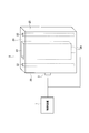
- FIG. 3 is a diagram showing the configuration of the anticorrosion device (system) of this embodiment.
- the anticorrosion device suppresses corrosion of the reinforcing bars inside the reinforced concrete by supplying water to the vicinity of the reinforcing bars of the reinforced concrete and removing the water after the supply of water is confirmed. That is, the anticorrosive solution is stored in the solution storage portion surrounded by the concrete, and the anticorrosive solution permeates into the concrete by diffusion. When it is detected that the anticorrosion solution reaches the position of the reinforcing bar and further reaches the outer surface of the concrete, the stored anticorrosion solution is discharged in order to prevent the concrete from being destroyed due to freeze expansion of the anticorrosion solution.
- the anticorrosion device of this embodiment includes a control device 1 (control unit), a solution storage unit 23, a drainage unit 24, and a moisture detection unit 3.
- a plurality of reinforcing bars 22 are arranged inside the concrete 21.
- a solution storage section 23 for holding (storing) the anticorrosion solution is formed inside the concrete 21.
- the solution storage unit 23 is a space surrounded by the concrete 21 and is an area where the anticorrosive solution is stored.
- the solution storage unit 23 is preliminarily formed as a product shape in the reinforced concrete structure 2. Further, the solution storage unit 23 may be formed later in the concrete 21 portion of the reinforced concrete structure 2.
- the anticorrosive solution permeates and diffuses into the vicinity of the reinforcing bar 22 through the concrete 21 to passivate the concrete 21 in the vicinity of the reinforcing bar 22 by alkalizing the reinforcing bar 22 and to prevent corrosion by solute precipitation in the anticorrosive solution. It is a solution that forms a conductive coating on the surface of the reinforcing bar 22.
- the anticorrosive solution may be stored in the solution storage unit 23 in advance.
- the anticorrosive solution may be supplied to the solution storage unit 23 at an arbitrary timing, such as when a crack (crack) that causes corrosion of the reinforcing bar 22 is generated on the surface 25 of the reinforced concrete structure 2.
- the surface 25 is an outer surface (exposed surface) where the concrete 21 of the reinforced concrete structure 2 contacts the outside.
- the reinforced concrete structure 2 also includes a drainage unit 24 (drainage mechanism) that drains the anticorrosion solution stored in the solution storage unit 23.
- the drainage unit 24 detects the penetration of the anticorrosive solution to the surface 25 of the reinforced concrete structure 2 and then detects the anticorrosive solution from the solution storage unit 23 to the outside of the reinforced concrete structure 2 (for example, underground).
- the drainage unit 24 is, for example, a drainage valve that opens and closes according to a control signal from the control device 1, or a drainage pump that operates according to the control signal.
- the moisture detector 3 detects that the anticorrosive solution has penetrated to the surface 25 of the concrete.
- the moisture detector 3 is installed on the surface 25 of the concrete structure 2 and measures the moisture value of the surface 25 of the reinforced concrete structure 2. Then, the moisture detector 3 detects that the anticorrosive solution has penetrated to the surface 25 of the concrete when the moisture value of the surface 25 of the reinforced concrete structure 2 exceeds a predetermined value, and transmits a detection signal to the control device 1. To do.
- the control device 1 is connected to the drainage unit 24 and the moisture detector 3 electrically, physically, or via a network.
- a computer such as a personal computer is used.
- the control device 1 sends a control signal to the drainage unit 24 to control and operate the drainage unit 24.
- the drainage unit 24 drains the anticorrosion solution stored in the solution storage unit 23 to the outside of the reinforced concrete structure 2.
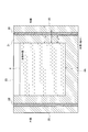
- Anticorrosion solution 4 is a sectional view of the reinforced concrete structure 2 shown in FIG. In FIG. 4, the anticorrosion solution 4 is stored in the solution storage unit 23. Anticorrosion solution 4 has a pH value in the range of pH 7 to pH 12. That is, the anticorrosion solution 4 is an alkaline solution.
- the anticorrosion solution 4 may also include at least one of sodium hydrogen carbonate, potassium hydroxide, sodium hydroxide and calcium hydroxide.
- the anticorrosion solution 4 may contain any one of sodium hydrogen carbonate, potassium hydroxide, sodium hydroxide and calcium hydroxide as a main component.
- the main component means that the concentration is at least 0.1% or more.
- the anticorrosion solution 4 since the water content of the anticorrosion solution 4 is alkalized by elution of calcium hydroxide from the non-neutralized area of the concrete, rainwater is used as a water supply source, and the supply of the anticorrosion solution 4 is unnecessary. Is possible. That is, the anticorrosion solution 4 may be a solution that is alkalized by using rainwater as a solvent and elution of calcium hydroxide in the non-neutralized region of the concrete 21 into the rainwater. In this case, the upper portion of the solution storage unit 23 is opened and rainwater is stored in the solution storage unit 23.
- the anticorrosion solution 4 when neutral or less neutral water is used as the anticorrosion solution 4, since it may accelerate deterioration of concrete, it is mainly composed of sodium hydrogen carbonate, potassium hydroxide, sodium hydroxide, calcium hydroxide or the like. It is desirable to use a neutral to alkaline anticorrosive solution 4.
- the drainage unit 24 of the present embodiment may have a drainage valve that can be opened and closed to drain the anticorrosion solution 4 from the bottom of the solution storage unit 23, for example.
- the drain valve is closed and the anticorrosive solution 4 is not drained from the solution storage unit 23 until the moisture detector 3 detects that the anticorrosive solution 4 has penetrated into the surface 25 of the reinforced concrete structure 2.
- the drain valve is activated and the drain valve is opened in response to the control signal from the control device 1, and the anticorrosive solution 4 is drained. It is discharged to the outside such as underground through 24.
- the drainage section 24 may have a drainage pump for discharging the anticorrosion solution 4 from the solution storage section 23.
- the drainage pump operates in accordance with the control signal from the control device 1, and the anticorrosion solution 4 passes through the drainage unit 24 to the ground or the like. Is discharged to the outside.
- FIG. 5 is a diagram showing an example of a processing flow of anticorrosion processing.
- the control device 1 stops the operation of the drainage unit 24 to store the anticorrosion solution 4 in the solution storage unit 23 (step S1).
- the drainage valve of the drainage unit 24 is in a closed state, or the drainage pump of the drainage unit 24 is in a non-operating state.
- step S2 Supplying the anticorrosion solution 4 to the solution storage section 23 surrounded by the concrete 21 while the drainage section 24 is not operating (step S2).
- step S2 When using rainwater as the solvent of the anticorrosion solution 4, wait for it to rain.
- the wetting process is started by supplying the anticorrosion solution 4 to the solution storage unit 23.
- the anticorrosion solution 4 permeates and diffuses into the concrete 21, so that it penetrates into the vicinity of the reinforcing bar 22 through the concrete 21, and the concrete 21 near the reinforcing bar 22 is alkalized to passivate the reinforcing bar 22.
- the moisture detector 3 determines whether or not the anticorrosive solution 4 has penetrated to the surface 25 of the concrete 21 (step S3).
- the moisture detector 3 sends a detection signal to the controller 1.
- the control device 1 receives the detection signal, the control device 1 transmits a control signal for draining the water to the drainage unit 24.
- the drainage unit 24 operates according to the control signal and drains the anticorrosion solution 4 in the solution storage unit 23 to the outside of the reinforced concrete structure 2 (step S4).
- the anticorrosion solution 4 is drained, the concrete 21 is naturally dried and moisture is removed from the concrete 21. That is, the discharging step (drying step) is started and the water is removed, solutes (eg, calcium hydroxide, calcium carbonate, etc.) in the anticorrosion solution 4 are deposited, and the anticorrosion coating is formed on the surface of the reinforcing bar 22. It is formed.
- the anticorrosion solution 4 is stored in the solution storage unit 23, and the anticorrosion solution 4 permeates into the vicinity of the reinforcing bar 22 through the concrete 21, so that the concrete 21 near the reinforcing bar 22 is alkalized and the reinforcing bar 22 The surface can be passivated. Further, in the present embodiment, the anticorrosion solution 4 is discharged and the concrete 21 is naturally dried, so that the anticorrosion coating formed by the precipitation of the solute in the anticorrosion solution 4 can be formed on the reinforcing bar 22.
- the alkali component of the anticorrosion solution 4 is neutralized to form an anticorrosion coating, and the anticorrosion coating is the surface of the reinforcing bar 22. Is formed so as to cover the. Thereby, anticorrosion performance is exhibited.
- the anticorrosive coating is formed by neutralizing the alkaline component of the anticorrosive solution 4 or the alkaline component leached from the concrete 21 by impregnating rainwater by removing water.
- the anticorrosion solution 4 containing calcium hydroxide as the main component of concrete is used, the neutralized concrete where cracks occur is alkalized in the wetting process, and calcium hydroxide and An anticorrosive coating is formed due to the precipitation of calcium carbonate. Calcium carbonate is deposited by the contact and reaction of calcium hydroxide with carbon dioxide in the air.
- the moisture detection unit 3 installed on the surface of the reinforced concrete structure 2 detects the anticorrosion solution 4, and also the concrete 21 is dried by natural drying. For this reason, the state in which the anticorrosion solution 4 is impregnated in the concrete 21 can be maintained for a relatively long time.
- the drainage section 24 of the present embodiment shown in FIG. 3 includes a drainage mechanism such as a drainage valve or a drainage pump, which is different from the concrete 21.
- the drainage part of this modification drains the anticorrosion solution 4 to the outside by adjusting the thickness of a part of the concrete 21 surrounding the solution storage part 23.
- FIG. 6 is a diagram for explaining the drainage unit 24A of this modification.
- a drainage unit 24A made of the same material as the concrete 21 is provided instead of the drainage unit 24 shown in FIG. 4.
- the water content detection unit 3 and the control device 1 are unnecessary. Others are the same as those of the embodiment shown in FIGS. 3 and 4.
- the anticorrosion solution 4 is automatically discharged from the solution storage unit 23 by setting the thickness t of a part of the solution storage unit 23 to a thickness within the range of the following formula.
- a is the thickness of the concrete 21 from the solution storage unit 23 to the reinforcing bar 22, and b is the thickness of the entire concrete 21.
- the thickness t of the drainage portion 24A is set to a or more, and the drainage portion 24A is made of concrete having the same configuration as the concrete 21 of the reinforced concrete structure 2 so that at least the time required for the anticorrosion solution 4 to reach the reinforcement 22 is stored. It becomes possible to hold the anticorrosion solution 4 in the portion 23.
- the thickness of the drainage section 24A is the thickness from the bottom of the solution storage section 23 to the outside of the reinforced concrete structure 2 in the illustrated example.
- the drainage section 24A of this modification is formed of the same concrete as the concrete 21 of the reinforced concrete structure 2, and the thickness t of the drainage section 24A is the thickness of the concrete 21 between the solution storage section 23 and the reinforcing bar 22. It is a or more and less than the thickness b to the surface 25 of the concrete 21 through the solution storage unit 23 and the reinforcing bar 22. In this way, by setting the thickness t of the drainage portion 24A to be a or more, after the anticorrosion solution 4 reaches the reinforcing bar 22, the anticorrosion solution 4 diffuses and is discharged to the outside of the reinforced concrete structure 2.
- the present embodiment it is possible to suppress the corrosion of the reinforcing bars 22 inside the reinforced concrete and easily repair the reinforced concrete at low cost. That is, conventionally, in order to repair the cracked portion of the reinforced concrete structure, a large-scale device such as a concrete machine tool or an electrochemical device was required, and a complicated process such as removal of concrete was required, but in the present embodiment, The reinforced concrete structure 2 can be repaired by imparting the anticorrosion effect to the reinforcing bar by a simple method of infiltrating the anticorrosion solution 4 into the concrete, discharging the anticorrosion solution 4 and naturally drying.
- the present embodiment is a technique useful as a measure when a crack is detected in the inspection work of a reinforced concrete structure.
- the anticorrosive solution 4 is discharged from the solution storage unit 23 after the anticorrosive solution 4 is supplied near the reinforcing bars 22.
- the reinforcing bar 22 can be protected from corrosion, and the stress load on the reinforced concrete structure 2 due to freeze expansion of the corrosion preventing solution 4 can be prevented.
- the control device 1 described above includes, for example, a CPU (Central Processing Unit, processor), a memory, a storage (HDD: Hard Disk Drive, SSD: Solid State Drive), a communication device, an input device, A general-purpose computer system including an output device can be used.
- each function of the control device 1 is realized by the CPU executing the program for the control device 1 loaded on the memory.
- the program for the control device 1 can be stored in a computer-readable recording medium such as a HDD, SSD, USB memory, CD-ROM, DVD-ROM, MO, or can be distributed via a network.
- the present invention is not limited to the above-described embodiment, and various modifications can be made within the scope of the gist thereof.
- the moisture detector 3 transmits the detection signal to the controller 1, and the controller 1 transmits the control signal to the drain 24.
- the water content detection unit 3 and the drainage unit 24 are connected electrically, physically, or via a network, and the water content detection unit 3 transmits the detection signal directly to the water drainage unit 24, and the water drainage unit 24 detects the detection signal. May be activated by receiving the. In this case, the control device 1 is unnecessary.
- Control device 2 Reinforced concrete structure 21: Concrete 22: Reinforcing bar 23: Solution storage part 24, 24A: Drain part 25: Surface 3: Moisture detection part
Landscapes
- Chemical & Material Sciences (AREA)
- Engineering & Computer Science (AREA)
- Ceramic Engineering (AREA)
- Materials Engineering (AREA)
- Organic Chemistry (AREA)
- Structural Engineering (AREA)
- Architecture (AREA)
- Inorganic Chemistry (AREA)
- Life Sciences & Earth Sciences (AREA)
- Civil Engineering (AREA)
- Wood Science & Technology (AREA)
- Mechanical Engineering (AREA)
- Chemical Kinetics & Catalysis (AREA)
- Health & Medical Sciences (AREA)
- Analytical Chemistry (AREA)
- Electrochemistry (AREA)
- Biodiversity & Conservation Biology (AREA)
- Ecology (AREA)
- Environmental & Geological Engineering (AREA)
- Environmental Sciences (AREA)
- Physics & Mathematics (AREA)
- Dispersion Chemistry (AREA)
- Pathology (AREA)
- Biochemistry (AREA)
- General Health & Medical Sciences (AREA)
- General Physics & Mathematics (AREA)
- Immunology (AREA)
- Metallurgy (AREA)
- General Chemical & Material Sciences (AREA)
- Working Measures On Existing Buildindgs (AREA)
- Testing Resistance To Weather, Investigating Materials By Mechanical Methods (AREA)
Abstract
鉄筋コンクリートを簡易に低コストで補修する。鉄筋コンクリートのコンクリート21内部に保持された防食溶液4を、コンクリート21を介して鉄筋22の近傍に浸透させて鉄筋22を不働体化させる湿潤工程と、防食溶液4がコンクリート21の表面25まで浸透したことを検知する検知工程と、検知工程で防食溶液4を検知した後に、防食溶液4をコンクリート21の外部に排出し、鉄筋22の表面に防食性被膜を形成する排水工程とを備える。
Description
本発明は、鉄筋コンクリートの防食方法および防食装置に関する。
鉄筋コンクリート内部の鉄筋は、コンクリートがアルカリ性であることから不働態化しており、コンクリートが健全な限り鉄筋の健全性も保たれる(非特許文献1)。
ただし、コンクリートが中性化した場合には鉄筋は腐食する恐れがある。特に、コンクリートにひび割れが生じた場合には、ひび割れた箇所の内部でコンクリートの中性化が急速に進行し、ひび割れた箇所の鉄筋が早期に腐食する(非特許文献2)。
そのため、鉄筋コンクリート構造物においては、十分なかぶり厚が求められるとともに、ひび割れが生じた鉄筋コンクリートに対しては、電気化学的工法による補修が施される(非特許文献3)。電気化学的工法は、電気化学装置を使用して劣化した既設コンクリート構造物に対して大きな電流を短期間流すことで、脱塩して補修する技術である。
原, "金属の腐食の基礎概念",J.Vac.soc., vol.44_860
半田,"コンクリート中鉄筋の水素による遅れ破壊",IEICE Technical Report, R2009-47, pp.7-10(2009)
上田, "コンクリート構造物の劣化と問題点",材料と環境, 59, pp.111-116(2010)
遠藤, "表面含浸工法による劣化抑制対策の現状と課題",コンクリート工学, 48, pp.97-100(2010)
山辺, "表面含浸材の施工の違いがコンクリートの耐久性に与える影響",第39回土木学会関東支部技術研究発表会, V-35
"Standard Test Method for Corrosion Potentials of Uncoated Reinforcing Steel in Concrete",ASTM C 876-15, Annual book of ASTM Standards, vol. 03.02,
中性化が進行した鉄筋コンクリートに対して、電気化学的工法による再アルカリ化を実施するには、鉄筋に電気的接続をする必要があるため、一部のコンクリートを斫り、鉄筋を露出するなど破壊を伴う施工が必要となる。
また、表面含浸材を用いた防食工法では破壊が不要であるが、既設構造物への効果は未知である(非特許文献4、非特許文献5)。
本発明は、前記課題に鑑みてなされたものであり、本発明の目的は、電気化学装置などの特別な機械を用いることなく、鉄筋コンクリートを簡易に低コストで補修することにある。
上記目的を達成するため、本発明の一態様は、鉄筋コンクリートの鉄筋の腐食を抑制する防食方法であって、前記鉄筋コンクリートのコンクリート内部に保持された防食溶液を、前記コンクリートを介して前記鉄筋の近傍に浸透させて前記鉄筋を不働体化させる湿潤工程と、前記防食溶液が前記コンクリートの表面まで浸透したことを検知する検知工程と、前記検知工程で前記防食溶液を検知した後に、前記防食溶液を前記コンクリートの外部に排出し、前記鉄筋の表面に防食性被膜を形成する排水工程と、を備える。
本発明の一態様は、鉄筋コンクリートの鉄筋の腐食を抑制する防食装置であって、前記鉄筋コンクリートのコンクリート内部に形成され、防食溶液を保持する貯蔵部と、前記防食溶液が前記コンクリートの表面まで浸透したことを検知する検知部と、前記検知部が前記防食溶液を検知した後に、前記貯蔵部から前記防食溶液を排出する排水部と、を有し、前記防食溶液は、前記コンクリートを介して前記鉄筋の近傍に浸透して前記鉄筋を不働体化し、前記鉄筋の表面に防食性被膜を形成する溶液である。
本発明の一態様は、鉄筋コンクリートの鉄筋の腐食を抑制する防食装置であって、前記鉄筋コンクリートのコンクリート内部に形成され、防食溶液を保持する貯蔵部と、前記溶蔵部から前記防食溶液を排出する排水部と、を有し、前記防食溶液は、前記コンクリートを介して前記鉄筋の近傍に浸透して前記鉄筋を不働体化し、前記鉄筋の表面に防食性被膜を形成する溶液であり、前記排水部は、前記コンクリートと同じコンクリートで形成され、前記排水部の厚さは、前記貯蔵部と前記鉄筋との間のコンクリートの厚さ以上であって、前記貯蔵部と前記鉄筋を介した前記コンクリートの表面までの厚さ未満である。
本発明によれば、鉄筋コンクリートを簡易に低コストで補修することができる。
以下、本発明の実施の形態について、図面を参照して説明する。
鉄筋コンクリートは、内部の鉄筋がコンクリートの強度を高める役割を持つことに加え、アルカリ性のコンクリートが鉄筋を覆うことで鉄筋を防食する。ひび割れのない健全な鉄筋コンクリートの中の鉄筋は、コンクリートのアルカリ環境に覆われているため不働態化している。しかし、ひび割れが生じた鉄筋コンクリートでは、ひび割れた部分のコンクリート内部の中性化が進行し、脱不働態化して鉄筋の腐食が進行する。
本実施形態は、ひび割れが生じた鉄筋コンクリート構造物など、中性化が進行した鉄筋コンクリートに対して、鉄筋コンクリートに破壊を伴う施工をすることなく、鉄筋を防食する技術である。
コンクリートにひび割れが生じると、ひび割れ内部が中性化し、ここに中性から酸性の水分が侵入した際に鉄筋が腐食する。しかし、ひび割れ内部が中性化した場合でも、アルカリ性の溶液を鉄筋近傍に滞留させることで防食することが可能となる。
また、コンクリートの中性化の深さ(進度)は、1年で数mm単位であることから、コンクリートには未中性化領域が多く残っている。そのため、ひび割れ内部に雨水などの中性から酸性の水分が侵入した場合でも、この水分が滞留した場合には、滞留した水分に未中性化領域のコンクリートの水酸化カルシウムが溶解し、コンクリートを介して拡散することで、鉄筋近傍がアルカリ環境に変化する。
したがって、鉄筋コンクリートにアルカリから中性の水分を供給し、鉄筋近傍にアルカリ性の水分を保持させることができれば、鉄筋を防食できる。
図1は、電位測定の結果を示す図である。図1は、0.1mm幅のひび割れを有する鉄筋コンクリートの供試体に対し、7時間の水浸漬による湿潤過程と、41時間の恒温槽設置(60℃維持)による乾燥過程を1サイクルとする乾湿繰り返し試験を実施したのち、湿度約70%の環境に放置した際の電位測定の結果を示したものである。図1では、乾湿繰り返し試験を継続した期間(0~40日)では、電位の卑化が示され、湿度約70%の環境に放置した期間(100日~)では電位の貴化が示されている。なお、40~100日の期間の測定データはないが、電位は-350mVから-200mVまで緩やかに上昇していると考えらえる。
非特許文献6のAPPENDIX X1.1.3によれば、ある領域の電位が-350mV vs. CSEよりもマイナスの場合、90%以上の確率でその領域の鉄筋が腐食していると判定される。このことから、乾湿繰り返しにより腐食が進行しているとみなすことができる。一方、電位の貴化は腐食の停止を示しており、湿度70%の環境に放置することにより、ひび割れ内部に水分が滞留した結果と考えられ、水分の滞留が防食効果を有することが示されている。
滞留した水分がアルカリ化され、その後蒸発する際には、水分中の溶質を含む防食性被膜が形成される。
図2は、防食性被膜を形成させた鋼材(被膜あり)と、防食性被膜のない鋼材(被膜なし)とをアルカリ環境であるアルカリ溶液中に浸漬し、その後、環境が中性化していく際の電荷移動抵抗の変化を示したものである。鋼材はいずれもSS400を用いた。防食性被膜がない場合には、pHが10程度まで低下すると、電荷移動抵抗が低下し始める。電荷移動抵抗の低下は腐食が進むことを意味することから、環境の中性化に伴い腐食が進行したとみなせる。一方、防食性被膜を有する鋼材は、pHが10程度まで低下し、環境の中性化が進行しても、電荷移動抵抗は低下しなかった。したがって、防食性被膜により鋼材を防食できることは明らかであり、防食性被膜の形成によりコンクリートのひび割れ内部の鉄筋を防食することができる。
上記のとおり、コンクリート内部で水分がアルカリ化し、アルカリ性の水分の除去過程においては防食性被膜が形成されることから、鉄筋近傍に水分を供給することで鉄筋を不働態化した後は水分を除去しても防食性被膜は形成されたままの状態とすることができる。
なお、水分をコンクリートに供給することで防食効果が得られるが、一方で、滞留した水分は冬季に凍結した際に体積膨張するため、コンクリート構造物に応力負荷がかかり、破壊される恐れがある。したがって、再不働態化が十分進行した後には、凍結が発生するような低温環境においては、滞留した水分が除去されることが望ましい。
図3は、本実施形態の防食装置(システム)の構成を示す図である。防食装置は、鉄筋コンクリートの鉄筋近傍への水分の供給と、水分供給が確認された後に水分の除去を実現することで、鉄筋コンクリート内部の鉄筋の腐食を抑制する。すなわち、コンクリートに囲まれた溶液貯蔵部に防食溶液を貯蔵し、防食溶液は拡散によりコンクリート内部に浸透する。防食溶液が鉄筋の位置に達し、さらにコンクリートの外表面に到達したことを検知すると、防食溶液の凍結膨張によるコンクリートの破壊を防ぐため貯蔵している防食溶液を排出する。
本実施形態の防食装置は、制御装置1(制御部)と、溶液貯蔵部23と、排水部24と、水分検知部3と、を備える。
鉄筋コンクリート構造物2は、コンクリート21の内部に複数の鉄筋22が配置されている。本実施形態では、コンクリート21の内部に、防食溶液を保持(貯蔵)するための溶液貯蔵部23が形成されている。溶液貯蔵部23は、コンクリート21に囲まれた空間であって、防食溶液が溜められる領域である。溶液貯蔵部23は、鉄筋コンクリート構造物2に製品形状としてあらかじめ形成されているものとする。また、鉄筋コンクリート構造物2のコンクリート21部分に、後から溶液貯蔵部23を形成してもよい。
防食溶液は、コンクリート21を介して鉄筋22の近傍に浸透および拡散することで、鉄筋22近傍のコンクリート21をアルカリ化により鉄筋22を不働体化するとともに、防食溶液の中の溶質の析出による防食性被膜を鉄筋22の表面に形成する溶液である。
防食溶液は、あらかじめ溶液貯蔵部23に貯蔵されていてもよい。あるいは、鉄筋コンクリート構造物2の表面25に、鉄筋22の腐食を進行させる要因となるひび(亀裂)が発生した際などの任意のタイミングで、溶液貯蔵部23に防食溶液を供給してもよい。表面25は、鉄筋コンクリート構造物2のコンクリート21が外部と接する外表面(露出面)である。
また、鉄筋コンクリート構造物2は、溶液貯蔵部23に貯蔵された防食溶液を排水する排水部24(排水機構)を備える。排水部24は、防食溶液が鉄筋コンクリート構造物2の表面25まで浸透したことを水分検知部3が検知した後に、防食溶液を溶液貯蔵部23から鉄筋コンクリート構造物2の外部(例えば、地中など)に排出する。排水部24は、例えば、制御装置1からの制御信号に応じて開閉する排水弁、または、制御信号に応じて作動する排水ポンプなどである。
水分検知部3(水分センサ)は、防食溶液がコンクリートの表面25まで浸透したことを検知する。本実施形態では、水分検知部3は、コンクリート構造物2の表面25に設置され、鉄筋コンクリート構造物2の表面25の水分値を計測する。そして、水分検知部3は、鉄筋コンクリート構造物2の表面25の水分値が所定の値を超えた場合に、防食溶液がコンクリートの表面25まで浸透したと検知し、検知信号を制御装置1に送信する。
制御装置1は、排水部24および水分検知部3と電気的、物理的、またはネットワークを介して接続される。制御装置1には、例えば、パソコンなどのコンピュータを用いる。
制御装置1は、排水部24に制御信号を送信して、排水部24を制御および作動させる。排水部24は、制御装置1からの制御信号を受信すると、溶液貯蔵部23に貯蔵された防食溶液を鉄筋コンクリート構造物2の外部に排出する。
図4は、図3に示す鉄筋コンクリート構造物2の断面図である。図4では、溶液貯蔵部23に防食溶液4が貯蔵されている。防食溶液4は、pH7からpH12の範囲のpH値である。すなわち、防食溶液4は、アルカリ性の溶液である。
また、防食溶液4は、炭酸水素ナトリウム、水酸化カリウム、水酸化ナトリウムおよび水酸化カルシウムの少なくとも1つを含んでもよい。
また、防食溶液4は、炭酸水素ナトリウム、水酸化カリウム、水酸化ナトリウムおよび水酸化カルシウムのいずれか1つを主成分としてもよい。主成分とは、少なくとも0.1%以上の濃度とすることを意味する。
また、防食溶液4の水分は、コンクリートの未中性化領域からの水酸化カルシウムの溶出によりアルカリ化することから、水分の供給源として雨水を利用し、防食溶液4の供給を不要とすることが可能である。すなわち、防食溶液4は、雨水を溶媒とし、雨水にコンクリート21の未中性化領域の水酸化カルシウムが溶出することでアルカリ化した溶液であってもよい。この場合、溶液貯蔵部23の上部は開放されて、溶液貯蔵部23に雨水が溜められる。未中性化領域を残すコンクリート構造物2に対しては、雨水を溶媒とし、未中性化領域のコンクリート21からの水酸化カルシウムが雨水に溶出することで、雨水がアルカリ化し、防食性能を発現する。これにより、溶液貯蔵部23への防食溶液4の供給は不要となる。
ただし、中性以下の水分を防食溶液4として用いる場合には、コンクリートの劣化を促進する恐れがあることから、炭酸水素ナトリウム、水酸化カリウム、水酸化ナトリウム、水酸化カルシウムなどを主成分とする中性からアルカリ性の防食溶液4を用いることが望ましい。
本実施形態の排水部24は、例えば、溶液貯蔵部23の底部から防食溶液4を排出するための開閉可能な排水弁を有してもよい。水分検知部3が鉄筋コンクリート構造物2の表面25に防食溶液4が浸透したことを検知するまで、排水弁は閉じており、溶液貯蔵部23から防食溶液4は排水されない。一方、水分検知部3が表面25に防食溶液4が浸透したことを検知すると、制御装置1からの制御信号に応じて、排水弁が作動し、排水弁が開放され、防食溶液4が排水部24を介して、地中などの外部に排出される。
また、排水部24は、溶液貯蔵部23から防食溶液4を排出するための排水ポンプを有してもよい。水分検知部3が表面25に防食溶液4が浸透したことを検知すると、制御装置1からの制御信号に応じて、排水ポンプが作動し、防食溶液4が排水部24を介して、地中などの外部に排出される。
次に、本実施形態の防食処理について説明する。
図5は、防食処理の処理フローの一例を示す図である。まず、制御装置1は、溶液貯蔵部23に防食溶液4を貯蔵するために排水部24の作動を停止する(ステップS1)。例えば、排水部24の排水弁は閉じられた状態であり、または、排水部24の排水ポンプは作動していない状態である。
排水部24が作動していない状態で、コンクリート21に囲まれた溶液貯蔵部23に防食溶液4を供給する(ステップS2)。防食溶液4の溶媒に雨水を用いる場合は、雨が降るのを待つ。溶液貯蔵部23に防食溶液4が供給されることで、湿潤工程が開始される。湿潤工程では、防食溶液4がコンクリート21に浸透および拡散することで、コンクリート21を介して鉄筋22の近傍に浸透し、鉄筋22近傍のコンクリート21のアルカリ化により鉄筋22を不働体化する。
水分検知部3は、防食溶液4がコンクリート21の表面25まで浸透したか否かを判別する(ステップS3)。水分検知部3は、コンクリート21の表面25で防食溶液4を検知した場合(ステップS3:YES)、検知信号を制御装置1に送信する。制御装置1は、検知信号を受信すると、排水させるための制御信号を排水部24に送信する。
排水部24は、制御信号に従って作動し、溶液貯蔵部23の防食溶液4を鉄筋コンクリート構造物2の外部に排水する(ステップS4)。防食溶液4が排水されることで、コンクリート21は自然乾燥し、コンクリート21から水分が除去される。すなわち、排出工程(乾燥工程)が開始され、水分が除去されることで、防食溶液4の中の溶質(例えば水酸化カルシウム、炭酸カルシウムなど)が析出され、鉄筋22の表面に防食性被膜が形成される。
このように、本実施形態では、溶液貯蔵部23に防食溶液4を溜めて、防食溶液4がコンクリート21を介して鉄筋22近傍に浸透することで、鉄筋22近傍のコンクリート21がアルカリ化し、鉄筋22表面を不働態化することができる。また、本実施形態では、防食溶液4を排出し、コンクリート21を自然乾燥することで、防食溶液4の中の溶質の析出による防食性被膜を鉄筋22に形成することができる。すなわち、コンクリート21内部に含浸させた防食溶液4の水分を除去し、乾燥させることで、防食溶液4のアルカリ成分が中性化されて防食性被膜が形成され、当該防食性被膜が鉄筋22表面を覆うように固着形成される。これにより、防食性能が発現する。防食性被膜は、防食溶液4のアルカリ成分、または雨水の含浸によりコンクリート21から浸出したアルカリ成分が、水分の除去により中性化して形成されたものである。
なお、コンクリートの主成分である水酸化カルシウムを主成分とする防食溶液4を用いる場合、湿潤工程において、ひび割れが発生した部分の中性化したコンクリートをアルカリ化し、排出工程において、水酸化カルシウムおよび炭酸カルシウムの析出による防食性被膜が生成される。炭酸カルシウムは、水酸化カルシウムが空気中の二酸化炭素と接触および反応することで析出される。
また、本実施形態では、鉄筋コンクリート構造物2の表面に設置された水分検知部3が防食溶液4を検知し、また、自然乾燥によりコンクリート21を乾燥させる。このため、比較的長い時間、コンクリート21に防食溶液4を含浸させた状態を維持することができる。
<変形例>
次に、本実施形態の排水部24の変形例について説明する。図3に示す本実施形態の排水部24は、排水弁または排水ポンプなどのコンクリート21とは異なる排水機構を備えるものである。本変形例の排水部は、溶液貯蔵部23を囲む一部のコンクリート21の厚さを調整することで、防食溶液4を外部に排水する。
次に、本実施形態の排水部24の変形例について説明する。図3に示す本実施形態の排水部24は、排水弁または排水ポンプなどのコンクリート21とは異なる排水機構を備えるものである。本変形例の排水部は、溶液貯蔵部23を囲む一部のコンクリート21の厚さを調整することで、防食溶液4を外部に排水する。
図6は、本変形例の排水部24Aを説明するための図である。本変形例では、図4に示す排水部24のかわりに、コンクリート21と同じ材質のコンクリートである排水部24Aを有する。また、本変形例では、水分検知部3および制御装置1は不要である。その他は、図3および図4に示す実施形態と同様である。
本変形例では、溶液貯蔵部23の一部の厚さtを、下記の式の範囲の厚みにすることで自動的に溶液貯蔵部23から防食溶液4を排出する。
a≦t<b
図6に示すように、aは溶液貯蔵部23から鉄筋22までのコンクリート21の厚さであり、bはコンクリート21全体の厚さである。排水部24Aの厚さtをa以上とし、排水部24Aを鉄筋コンクリート構造物2のコンクリート21と同じ構成のコンクリートとすることで、少なくとも鉄筋22に防食溶液4が到達するのに要する時間、溶液貯蔵部23で防食溶液4を保持することが可能となる。排水部24Aの厚さは、図示する例では溶液貯蔵部23の底部から鉄筋コンクリート構造物2の外部までの厚さである。
図6に示すように、aは溶液貯蔵部23から鉄筋22までのコンクリート21の厚さであり、bはコンクリート21全体の厚さである。排水部24Aの厚さtをa以上とし、排水部24Aを鉄筋コンクリート構造物2のコンクリート21と同じ構成のコンクリートとすることで、少なくとも鉄筋22に防食溶液4が到達するのに要する時間、溶液貯蔵部23で防食溶液4を保持することが可能となる。排水部24Aの厚さは、図示する例では溶液貯蔵部23の底部から鉄筋コンクリート構造物2の外部までの厚さである。
すなわち、本変形例の排水部24Aは、鉄筋コンクリート構造物2のコンクリート21と同じコンクリートで形成され、排水部24Aの厚さtは、溶液貯蔵部23と鉄筋22との間のコンクリート21の厚さa以上であって、溶液貯蔵部23と鉄筋22を介したコンクリート21の表面25までの厚さb未満である。このように、排水部24Aの厚さtを、a以上とすることで、鉄筋22に防食溶液4が到達した後に、防食溶液4が拡散することで鉄筋コンクリート構造物2の外部に排出される。
以上説明した本実施形態および変形例では、鉄筋コンクリートのコンクリート21内部に保持された防食溶液4を、コンクリート21を介して鉄筋22の近傍に浸透させて鉄筋22を不働体化させる湿潤工程と、防食溶液4がコンクリート21の表面25まで浸透したことを検知する検知工程と、検知工程で防食溶液4を検知した後に、防食溶液4をコンクリート21の外部に排出し、鉄筋22の表面に防食性被膜を形成する排水工程とを備える。
これにより本実施形態では、鉄筋コンクリート内部の鉄筋22の腐食を抑制し、鉄筋コンクリートを簡易に低コストで補修することができる。すなわち、従来では、鉄筋コンクリート構造物のひび割れ部の補修には、コンクリート工作機や電気化学装置等の大型の装置が必要で、コンクリートの除去など煩雑なプロセスが必要であったが、本実施形態では、防食溶液4をコンクリートに浸透させ、防食溶液4を排出し自然乾燥させるという簡便な方法で、防食効果を鉄筋に付与し、鉄筋コンクリート構造物2の補修を実施することができる。
したがって本実施形態および変形例では、微小なひび割れが生じた鉄筋コンクリート構造物2に対し、鉄筋22の露出を伴う施工を要することなく、簡便かつ安価に鉄筋コンクリート構造物2の防食および補修が可能となる。また、本実施形態は、鉄筋コンクリート構造物の点検作業において、ひび割れを検知した際の処置としても有用な技術である。
また、本実施形態および変形例では、鉄筋22近傍に防食溶液4を供給した後で溶液貯蔵部23から防食溶液4を排出する。これにより、鉄筋22を防食することができるとともに、防食溶液4の凍結膨張による鉄筋コンクリート構造物2への応力負荷を防止することができる。
なお、上記説明した制御装置1には、例えば、CPU(Central Processing Unit、プロセッサ)と、メモリと、ストレージ(HDD:Hard Disk Drive、SSD:Solid State Drive)と、通信装置と、入力装置と、出力装置とを備える汎用的なコンピュータシステムを用いることができる。このコンピュータシステムにおいて、CPUがメモリ上にロードされた制御装置1用のプログラムを実行することにより、制御装置1の各機能が実現される。また、制御装置1用のプログラムは、HDD、SSD、USBメモリ、CD-ROM、DVD-ROM、MOなどのコンピュータ読取り可能な記録媒体に記憶することも、ネットワークを介して配信することもできる。
また、本発明は上記実施形態に限定されるものではなく、その要旨の範囲内で数々の変形が可能である。なお、上記実施形態では、水分検知部3は検知信号を制御装置1に送信し、制御装置1が排水部24に制御信号を送信することとした。しかしながら、水分検知部3と排水部24とが電気的、物理的、またはネットワークを介して接続され、水分検知部3が、検知信号を直接、排水部24に送信し、排水部24は検知信号を受信することで作動してもよい。この場合、制御装置1は不要である。
1 :制御装置
2 :鉄筋コンクリート構造物
21:コンクリート
22:鉄筋
23:溶液貯蔵部
24、24A:排水部
25:表面
3 :水分検知部
2 :鉄筋コンクリート構造物
21:コンクリート
22:鉄筋
23:溶液貯蔵部
24、24A:排水部
25:表面
3 :水分検知部
Claims (8)
- 鉄筋コンクリートの鉄筋の腐食を抑制する防食方法であって、
前記鉄筋コンクリートのコンクリート内部に保持された防食溶液を、前記コンクリートを介して前記鉄筋の近傍に浸透させて前記鉄筋を不働体化させる湿潤工程と、
前記防食溶液が前記コンクリートの表面まで浸透したことを検知する検知工程と、
前記検知工程で前記防食溶液を検知した後に、前記防食溶液を前記コンクリートの外部に排出し、前記鉄筋の表面に防食性被膜を形成する排水工程と、を備えること
を特徴とする防食方法。 - 鉄筋コンクリートの鉄筋の腐食を抑制する防食装置であって、
前記鉄筋コンクリートのコンクリート内部に形成され、防食溶液を保持する貯蔵部と、
前記防食溶液が前記コンクリートの表面まで浸透したことを検知する検知部と、
前記検知部が前記防食溶液を検知した後に、前記貯蔵部から前記防食溶液を排出する排水部と、を有し、
前記防食溶液は、前記コンクリートを介して前記鉄筋の近傍に浸透して前記鉄筋を不働体化し、前記鉄筋の表面に防食性被膜を形成する溶液であること
を特徴とする防食装置。 - 前記排水部は、前記貯蔵部から前記防食溶液を排出する排水弁を有し、
前記検知部が前記防食溶液を検知すると、前記排水弁が作動すること
を特徴とする請求項2に記載の防食装置。 - 前記排水部は、前記貯蔵部から前記防食溶液を排出する排水ポンプを有し、
前記検知部が前記防食溶液を検知すると、前記排水ポンプが作動すること
を特徴とする請求項2に記載の防食装置。 - 鉄筋コンクリートの鉄筋の腐食を抑制する防食装置であって、
前記鉄筋コンクリートのコンクリート内部に形成され、防食溶液を保持する貯蔵部と、
前記貯蔵部から前記防食溶液を排出する排水部と、を有し、
前記防食溶液は、前記コンクリートを介して前記鉄筋の近傍に浸透して前記鉄筋を不働体化し、前記鉄筋の表面に防食性被膜を形成する溶液であり、
前記排水部は、前記コンクリートと同じコンクリートで形成され、前記排水部の厚さは、前記貯蔵部と前記鉄筋との間のコンクリートの厚さ以上であって、前記貯蔵部と前記鉄筋を介した前記コンクリートの表面までの厚さ未満であること
を特徴とする防食装置。 - 前記防食溶液は、pH7からpH12の範囲のpH値であること
を特徴とする請求項2から5のいずれか1項に記載の防食装置。 - 前記防食溶液は、雨水を溶媒とし、前記雨水に前記コンクリートの未中性化領域の水酸化カルシウムが溶出することでアルカリ化した溶液であること
を特徴とする請求項2から6のいずれか1項に記載の防食装置。 - 前記防食溶液は、炭酸水素ナトリウム、水酸化カリウム、水酸化ナトリウムおよび水酸化カルシウムの少なくとも1つを含むこと
を特徴とする請求項2から6のいずれか1項に記載の防食装置。
Priority Applications (1)
| Application Number | Priority Date | Filing Date | Title |
|---|---|---|---|
| US17/431,567 US12172183B2 (en) | 2019-02-20 | 2020-02-06 | Corrosion prevention method and corrosion prevention device |
Applications Claiming Priority (2)
| Application Number | Priority Date | Filing Date | Title |
|---|---|---|---|
| JP2019028058A JP7277713B2 (ja) | 2019-02-20 | 2019-02-20 | 防食方法および防食装置 |
| JP2019-028058 | 2019-02-20 |
Publications (1)
| Publication Number | Publication Date |
|---|---|
| WO2020170828A1 true WO2020170828A1 (ja) | 2020-08-27 |
Family
ID=72144249
Family Applications (1)
| Application Number | Title | Priority Date | Filing Date |
|---|---|---|---|
| PCT/JP2020/004447 Ceased WO2020170828A1 (ja) | 2019-02-20 | 2020-02-06 | 防食方法および防食装置 |
Country Status (3)
| Country | Link |
|---|---|
| US (1) | US12172183B2 (ja) |
| JP (1) | JP7277713B2 (ja) |
| WO (1) | WO2020170828A1 (ja) |
Cited By (2)
| Publication number | Priority date | Publication date | Assignee | Title |
|---|---|---|---|---|
| CN112221912A (zh) * | 2020-10-15 | 2021-01-15 | 中泽电气科技有限公司 | 一种不锈钢配电箱壳体的表面处理方法 |
| WO2024014003A1 (ja) * | 2022-07-15 | 2024-01-18 | 日本電信電話株式会社 | 腐食再現装置、制御装置、評価システム、制御方法、及びプログラム |
Families Citing this family (2)
| Publication number | Priority date | Publication date | Assignee | Title |
|---|---|---|---|---|
| JP7430121B2 (ja) | 2020-08-07 | 2024-02-09 | Koa株式会社 | シャント抵抗器に用いられる抵抗合金、抵抗合金のシャント抵抗器への使用及び抵抗合金を用いたシャント抵抗器 |
| JP7460932B2 (ja) * | 2020-10-19 | 2024-04-03 | 日本電信電話株式会社 | 決定装置、決定システム、および決定方法 |
Citations (5)
| Publication number | Priority date | Publication date | Assignee | Title |
|---|---|---|---|---|
| JPH0967937A (ja) * | 1995-08-31 | 1997-03-11 | Ohbayashi Corp | コンクリート構造物の改質方法 |
| JP3056298U (ja) * | 1998-07-30 | 1999-02-12 | 小沢コンクリート工業株式会社 | 雨水の地下浸透施設用ゴミ除去装置 |
| JP2007002585A (ja) * | 2005-06-27 | 2007-01-11 | Haseko Corp | コンクリート構造物への薬液含浸方法 |
| JP2010189871A (ja) * | 2009-02-16 | 2010-09-02 | Akio Miyamoto | 加圧式浸透装置 |
| JP2011153497A (ja) * | 2010-01-28 | 2011-08-11 | Maeda Corp | コンクリートの湿潤養生装置 |
Family Cites Families (8)
| Publication number | Priority date | Publication date | Assignee | Title |
|---|---|---|---|---|
| JPS60260620A (ja) * | 1984-06-08 | 1985-12-23 | Yokohama Rubber Co Ltd:The | 防食材組成物 |
| DD275157A3 (de) * | 1987-12-16 | 1990-01-17 | Bauakademie Ddr | Verfahren zur Herstellung eines Korrosionsschutzmittels für Stahlbewehrungen auf der Basis wäßriger Dispersionen |
| US5039556A (en) * | 1990-12-03 | 1991-08-13 | W. R. Grace & Co.-Conn. | Treating concrete structures to inhibit corrosion by heating the structure, cooling same under controlled temperature gradient, and applying an inhibiting agent to an internal portion of the structure |
| JP3524226B2 (ja) | 1995-07-27 | 2004-05-10 | 藤森工業株式会社 | 穀物等の加工装置 |
| JP3437920B2 (ja) * | 1997-12-26 | 2003-08-18 | 周一 今井 | コンクリ−ト構造物の亀裂補修剤及び防水・補修工法並びにコンクリ−トの改質方法 |
| WO2006021092A1 (en) * | 2004-08-25 | 2006-03-02 | Service Techno Science Inc. | Method for treating the internal surfaces of industrial buildings |
| JP4616419B1 (ja) * | 2010-06-14 | 2011-01-19 | 明雄 宮本 | 浸透剤浸透装置 |
| US20170044379A1 (en) * | 2015-08-12 | 2017-02-16 | Worcester Polytechnic Institute | Self-healing coating for reinforcement steel |
-
2019
- 2019-02-20 JP JP2019028058A patent/JP7277713B2/ja active Active
-
2020
- 2020-02-06 US US17/431,567 patent/US12172183B2/en active Active
- 2020-02-06 WO PCT/JP2020/004447 patent/WO2020170828A1/ja not_active Ceased
Patent Citations (5)
| Publication number | Priority date | Publication date | Assignee | Title |
|---|---|---|---|---|
| JPH0967937A (ja) * | 1995-08-31 | 1997-03-11 | Ohbayashi Corp | コンクリート構造物の改質方法 |
| JP3056298U (ja) * | 1998-07-30 | 1999-02-12 | 小沢コンクリート工業株式会社 | 雨水の地下浸透施設用ゴミ除去装置 |
| JP2007002585A (ja) * | 2005-06-27 | 2007-01-11 | Haseko Corp | コンクリート構造物への薬液含浸方法 |
| JP2010189871A (ja) * | 2009-02-16 | 2010-09-02 | Akio Miyamoto | 加圧式浸透装置 |
| JP2011153497A (ja) * | 2010-01-28 | 2011-08-11 | Maeda Corp | コンクリートの湿潤養生装置 |
Cited By (2)
| Publication number | Priority date | Publication date | Assignee | Title |
|---|---|---|---|---|
| CN112221912A (zh) * | 2020-10-15 | 2021-01-15 | 中泽电气科技有限公司 | 一种不锈钢配电箱壳体的表面处理方法 |
| WO2024014003A1 (ja) * | 2022-07-15 | 2024-01-18 | 日本電信電話株式会社 | 腐食再現装置、制御装置、評価システム、制御方法、及びプログラム |
Also Published As
| Publication number | Publication date |
|---|---|
| US20220134374A1 (en) | 2022-05-05 |
| JP2020134314A (ja) | 2020-08-31 |
| US12172183B2 (en) | 2024-12-24 |
| JP7277713B2 (ja) | 2023-05-19 |
Similar Documents
| Publication | Publication Date | Title |
|---|---|---|
| WO2020170828A1 (ja) | 防食方法および防食装置 | |
| Erdoğdu et al. | Accelerated testing of plain and epoxy-coated reinforcement in simulated seawater and chloride solutions | |
| Zhu et al. | Probabilistic analysis of reinforcement corrosion due to the combined action of carbonation and chloride ingress in concrete | |
| Franzoni et al. | Effects of rising damp and salt crystallization cycles in FRCM-masonry interfacial debonding: Towards an accelerated laboratory test method | |
| González et al. | On the effectiveness of realkalisation as a rehabilitation method for corroded reinforced concrete structures | |
| Ali et al. | An experimental study of electrochemical incompatibility between repaired patch concrete and existing old concrete | |
| Ahmad | Prediction of residual flexural strength of corroded reinforced concrete beams | |
| Bertolini et al. | Corrosion assessment and restoration strategies of reinforced concrete buildings of the cultural heritage | |
| JP5895522B2 (ja) | 屋外環境における鋼材の腐食量予測方法 | |
| JP7100262B2 (ja) | 鉄筋コンクリート構造物 | |
| Ilomets et al. | Impact of ETICS on corrosion propagation of concrete facade | |
| Caronge et al. | Application of sacrificial point anode for prevention of steel corrosion in cracked concrete | |
| US20210348389A1 (en) | Corrosion Prevention Method and Corrosion Prevention Device | |
| Sergi et al. | Control of reinforcement corrosion by surface treatment of concrete | |
| Breit et al. | Investigation on the effectiveness of the repair method 8.3''Corrosion protection by increasing electrical resistivity''in chloride‐containing concrete Part 1: Overview and recognition of Prof. Raupach's contribution | |
| Zelinka et al. | Assessment of fastener corrosion and salt damage in the bilge of the Eureka | |
| Bertolini et al. | Conservation techniques on the reinforced concrete pillars of the church of the San Carlo Borromeo hospital in Milan | |
| ElSafty et al. | Concrete repair and cathodic protection of corroded reinforced concrete structure | |
| Aglan et al. | Effect of long‐term exposure and delayed drying time on moisture and mechanical integrity of flooded homes | |
| Sandberg | Cost-effective service life design of concrete structures in saline environment | |
| van den Hondel | Results on the long-term performance and effectiveness of a galvanic CP system applied on a lightweight concrete bridge with prestressed steel as determined by depolarisation values and current densities | |
| Polder et al. | Electro active repair of concrete: innovation for increased repair durability | |
| van den Hondel et al. | A 5 year track record on a galvanic CP system applied on a light weight concrete bridge with prestressed steel–Developments in time of the effectiveness as determined by depolarisation values and current densities | |
| van den Hondel et al. | Application of a surface-applied cathodic protection system on a light weight concrete bridge–Part II: Developments in time of the effectiveness by potential decay values and current densities | |
| US11867609B2 (en) | Method and apparatus for accelerated corrosion testing |
Legal Events
| Date | Code | Title | Description |
|---|---|---|---|
| 121 | Ep: the epo has been informed by wipo that ep was designated in this application |
Ref document number: 20759659 Country of ref document: EP Kind code of ref document: A1 |
|
| NENP | Non-entry into the national phase |
Ref country code: DE |
|
| 122 | Ep: pct application non-entry in european phase |
Ref document number: 20759659 Country of ref document: EP Kind code of ref document: A1 |