WO2020170815A1 - モニタリング装置及びモニタリング方法 - Google Patents
モニタリング装置及びモニタリング方法 Download PDFInfo
- Publication number
- WO2020170815A1 WO2020170815A1 PCT/JP2020/004297 JP2020004297W WO2020170815A1 WO 2020170815 A1 WO2020170815 A1 WO 2020170815A1 JP 2020004297 W JP2020004297 W JP 2020004297W WO 2020170815 A1 WO2020170815 A1 WO 2020170815A1
- Authority
- WO
- WIPO (PCT)
- Prior art keywords
- response characteristic
- deposit
- response
- unit
- response characteristics
- Prior art date
- Legal status (The legal status is an assumption and is not a legal conclusion. Google has not performed a legal analysis and makes no representation as to the accuracy of the status listed.)
- Ceased
Links
Images






Classifications
-
- G—PHYSICS
- G01—MEASURING; TESTING
- G01B—MEASURING LENGTH, THICKNESS OR SIMILAR LINEAR DIMENSIONS; MEASURING ANGLES; MEASURING AREAS; MEASURING IRREGULARITIES OF SURFACES OR CONTOURS
- G01B11/00—Measuring arrangements characterised by the use of optical techniques
- G01B11/08—Measuring arrangements characterised by the use of optical techniques for measuring diameters
-
- G—PHYSICS
- G01—MEASURING; TESTING
- G01B—MEASURING LENGTH, THICKNESS OR SIMILAR LINEAR DIMENSIONS; MEASURING ANGLES; MEASURING AREAS; MEASURING IRREGULARITIES OF SURFACES OR CONTOURS
- G01B11/00—Measuring arrangements characterised by the use of optical techniques
- G01B11/08—Measuring arrangements characterised by the use of optical techniques for measuring diameters
- G01B11/10—Measuring arrangements characterised by the use of optical techniques for measuring diameters of objects while moving
-
- G—PHYSICS
- G01—MEASURING; TESTING
- G01N—INVESTIGATING OR ANALYSING MATERIALS BY DETERMINING THEIR CHEMICAL OR PHYSICAL PROPERTIES
- G01N21/00—Investigating or analysing materials by the use of optical means, i.e. using sub-millimetre waves, infrared, visible or ultraviolet light
- G01N21/17—Systems in which incident light is modified in accordance with the properties of the material investigated
- G01N21/25—Colour; Spectral properties, i.e. comparison of effect of material on the light at two or more different wavelengths or wavelength bands
- G01N21/27—Colour; Spectral properties, i.e. comparison of effect of material on the light at two or more different wavelengths or wavelength bands using photo-electric detection ; circuits for computing concentration
-
- G—PHYSICS
- G01—MEASURING; TESTING
- G01N—INVESTIGATING OR ANALYSING MATERIALS BY DETERMINING THEIR CHEMICAL OR PHYSICAL PROPERTIES
- G01N21/00—Investigating or analysing materials by the use of optical means, i.e. using sub-millimetre waves, infrared, visible or ultraviolet light
- G01N21/17—Systems in which incident light is modified in accordance with the properties of the material investigated
- G01N21/47—Scattering, i.e. diffuse reflection
Definitions
- the present invention relates to a monitoring device and a monitoring method, for example, for monitoring the state of a multi-layered or mixed sediment of a road surface or a structure.
- Patent Documents 1 and 2 describe a technique for monitoring the depth and quality of snowfall by using transmitted electromagnetic waves and scattered electromagnetic waves.
- Patent Documents 1 and 2 are intended to monitor a single layer of sediment such as snow, but in reality, not only one layer but also different types of snow, or a plurality of types of snow and an ice film.
- the deposit may be multi-layered.
- a plurality of types of substances may be mixed such that water and mud are mixed in the snow.
- an object of the present invention is to provide a monitoring device and a monitoring method capable of monitoring the state of a multi-layered or mixed deposit.
- a monitoring device is an observation unit that irradiates a deposit with electromagnetic waves and observes response characteristics of the electromagnetic waves obtained from the deposit, and an observation result of the observation unit.
- An estimation unit that estimates the state of a plurality of objects that form the multilayered or mixed deposit based on the obtained at least two response characteristics.
- the response characteristic to the electromagnetic wave of the first property and the response characteristic to the electromagnetic wave of the second property are response characteristics due to irradiation of two types of laser light having different wavelengths or laser light having different polarizations.
- response characteristics such as “total light intensity” and “peak brightness” of scattered light, which are different types of response characteristics.
- the number of unknown parameters in a multi-layered or mixed deposit that is, the state of a plurality of constituents of the deposit is estimated.
- the electromagnetic response characteristics for example, light scattering intensity, light transmission intensity, etc.
- n is a natural number.
- change the properties of the electromagnetic waves for example, the wavelength and polarization of the electromagnetic waves
- change the type of response characteristics for example, light scattering intensity, light transmission intensity, etc.
- At least two response characteristics are obtained as measurement quantities necessary to estimate the n parameters.
- the states of a plurality of objects constituting the multilayered or mixed deposit are estimated.
- the estimation unit is obtained from data on a relationship between a state of a plurality of objects forming the multilayered or mixed deposit and at least two of the response characteristics, From the relationship between the scatter diagram showing the scatter of the state of the object with the response characteristic as the coordinate axis and at least two of the response characteristics obtained from the observation unit, a plurality of objects that constitute the multilayered or mixed deposit The state may be estimated.
- the state of a plurality of objects constituting the multi-layered or mixed deposit the response characteristic to the electromagnetic wave of the first property, and the response characteristic to the electromagnetic wave of the second property.
- a storage unit that stores data regarding the relationship between the response characteristic of the data stored in the storage unit and at least two response characteristics obtained from the observation unit.
- the state of a plurality of objects that constitute the multi-layered or mixed deposit may be estimated.
- the estimation unit may use a two-dimensional scattering image as the response characteristic of the data accumulated in the storage unit and at least two two-dimensional scattering images as the response characteristic obtained from the observation unit.
- the estimation unit obtains from a feature amount obtained from a two-dimensional scattering image as the response characteristic of the data accumulated in the storage unit and at least two two-dimensional scattering images as the response characteristic obtained from the observation unit. It is also possible to estimate the state of a plurality of objects constituting the multi-layered or mixed deposit by pattern matching with the feature amount.
- the estimation unit calculates a correlation between a state of a plurality of objects forming the multilayered or mixed deposit and at least two response characteristics obtained from the observation unit. Substituting at least two of the response characteristics obtained from the observation unit into two or more equations shown and solving these equations simultaneously to solve a plurality of layers forming the multilayered or mixed deposit The state of the object may be estimated.
- a monitoring method irradiates a deposit with an electromagnetic wave, observes a response characteristic of the electromagnetic wave obtained from the deposit, and from the observation result, the response characteristic to the electromagnetic wave of the first property, At least two of the response characteristic to the electromagnetic wave of the second property, the first type of the response characteristic, and the second type of the response characteristic are obtained, and multilayering is performed based on the obtained at least two of the response characteristics.
- the state of a plurality of objects forming the mixed deposit is estimated.
- FIG. 1 is a diagram showing the configuration of the monitoring device according to the first embodiment.
- the monitoring device 1 includes an observation unit 10, a storage unit 20, an estimation unit 30, and a display unit 40.
- the observation unit 10 includes a transmission unit 11, a reception unit 12, and a control unit 13.
- the transmission unit 11 and the reception unit 12 are arranged inside the housing 50.
- a window portion 51 made of a transparent member is provided on the top of the housing 50.
- the deposit 2 is deposited on the upper part of the housing 50.
- the monitoring device 1 is typically embedded under a road surface or a runway, has a window portion 51 on the same surface as the road surface or the runway, and monitors deposits 2 such as snow accumulated on the road surface or the runway. To do.
- the transmission unit 11 has a laser light source that transmits laser light as electromagnetic waves toward the deposit 2 through the window 51.
- the transmission unit 11 is configured to emit, for example, two types of laser light having different wavelengths or laser lights having different polarizations.
- the receiving unit 12 receives the scattered light of the laser light scattered by the deposit 2 through the window 51.
- the receiving unit 12 has a two-dimensional optical sensor including a CCD (Charge Coupled Device) for receiving scattered light scattered by the deposit 2.
- the receiving unit 12 has a filter for receiving a specific wavelength and a specific polarized laser beam.
- the control unit 13 causes the transmission unit 11 to transmit the laser light and causes the reception unit 12 to receive the scattered light with respect to the laser light.
- control unit 13 controls the transmission unit 11 to irradiate two types of laser light having different wavelengths or laser lights having different polarizations. Further, the control unit 13 controls, for example, the receiving unit 12 to receive a specific wavelength and receive a specific polarized laser beam. It should be noted that, for example, “total light amount” and “peak brightness” as response characteristics described later may be acquired by the observation unit 10, but may be acquired by the estimation unit 30 based on data from the reception unit 12. ..
- the storage unit 20 stores a correct answer data group described later.
- the estimation unit 30 creates a scatter diagram from the correct data group and estimates an unknown parameter of the deposit 2 from the scatter diagram. Although the estimation unit 30 creates the correct answer data or the scatter diagram from the group, the storage unit 20 may store the scatter diagram in advance.
- the display unit 40 displays the estimation result by the estimation unit 30.
- a two-layered deposit 2 was created using snow samples having different grain sizes, and a two-dimensional light scattering image was acquired by a trial observation unit 10.
- the data of one layer with uniform thickness and the data of two layers were compared.
- the process of estimating the particle size from the two-dimensional light scattering image is not quantitatively evaluated, but two different types of response characteristics, “total light amount” and “peak brightness” of scattered light are provided.
- the possibility of estimating the particle size by the method was examined by using a scatter diagram with "total light intensity” and "peak brightness” as coordinate axes.
- the "total light intensity" of scattered light is typically the total light intensity of the entire two-dimensional light scattering image, and the "peak brightness” of the scattered light is typically within the two-dimensional light scattering image. It is the largest brightness observed.
- the experiment was conducted in a laboratory controlled at -5°C.
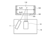
- An observation sample case 102 having a thickness of 5 mm with a transparent member 101 (corresponding to the window portion 51) attached to the bottom surface and an outer frame 103 having a thickness of 5 mm for two layers were prepared.
- a two-layer observation sample case 100 having a thickness of 10 mm was created by combining the observation sample case 102 and the outer frame 103.
- Snow A particle diameter 0.5 mm or less
- snow B particle diameter 2.0-2.8 mm
- four kinds of double-layered snow sample 110 are prepared by changing the combination thereof. Created.
- the observation sample case 102 is filled with snow in the lower layer (on the side close to the transparent member 101) to make the thickness uniform, and then the outer frame 103 is fitted to the observation sample case 102, It was created by filling the upper layer of snow and making the thickness uniform.
- the observation unit 10 was used for observation of double-layer snow.
- the transmission unit 11 having a laser light source was used to obliquely irradiate the double-layered snow sample 110 from below the transparent member 101.
- the scattered wave was detected by the receiving unit 12 installed vertically below the transmissive member 101.
- a CMOS camera was used as the receiving unit 12, and scattered waves from the double-layered snow sample 110 were detected as a two-dimensional light scattering distribution.
- FIG. 3 shows the observation results of the two-dimensional light scattering intensity distributions from the four types of double-layered snow samples 110 acquired by this configuration.
- the two-dimensional light scattering intensity distribution is acquired using two different wavelengths ⁇ 1 and ⁇ 2 in the laser light source of the transmission unit 11.
- the display of AB in FIG. 3 corresponds to that the upper layer is snow A and the lower layer is snow B.
- the lower layer is defined as the side close to the transmission unit 11 and the reception unit 12. It can be seen that the two-dimensional light scattering pattern changes because the amount and angle of scattered waves differ depending on the particle size. It is known from previous studies that the larger the particle size, the smaller the light scattering intensity, and we expected that observation results would be obtained according to this tendency.
- data is acquired by changing the type of response characteristic (for example, “total light intensity” and “peak brightness”) or by changing the property of laser light that is an electromagnetic wave (for example, two different wavelengths ⁇ 1 and ⁇ 2 ). It is expected that the state of the two layers can be estimated by applying pattern matching or the like.
- type of response characteristic for example, “total light intensity” and “peak brightness”
- property of laser light that is an electromagnetic wave for example, two different wavelengths ⁇ 1 and ⁇ 2 .
- total light intensity and peak brightness two kinds of different response characteristics
- the particle diameters of the upper layer and the lower layer can be estimated by using a scatter diagram with the “total light amount” and the “peak brightness” as coordinate axes. From the four types of two-dimensional light-scattering images at the wavelength ⁇ 1 as shown in FIG. 3, a scatter diagram having “total light intensity” and “peak brightness” as coordinate axes was created. The result is shown in FIG. Here, since the measurement was performed three times for each of the four two-layer states, the number of data points was 12, and all the data were standardized with respect to the maximum value of the data.
- the particle size of the lower layer can be grasped by grouping with a threshold value on the scatter diagram. It is possible. As a tendency, the light scattering intensity monotonically increases as the particle size decreases, so that the “peak brightness” and the “total light amount” monotonically increase. Since variations and outliers are mixed in the measured values in FIG. 4A, first, the average and standard deviation were derived for the measurement under the same conditions, and the results were plotted again as shown in FIG. 4B. Although not as remarkable as the change in the lower layer from FIG.
- the light scattering influences the state of the particle size in the upper layer, and the “peak brightness” and the “total light amount” monotonically increase as the particle size decreases. You can see the tendency. Therefore, it is considered that the upper layer can be similarly grouped.
- the upper layer can be similarly grouped.
- the peak luminance and the wavelength ⁇ 1 of the wavelength ⁇ 1 are the response characteristics of the respective wavelengths ⁇ 1 and ⁇ 2 , for example, It is considered possible to estimate the particle diameters of the upper and lower layers by creating a scatter diagram with the peak luminance of 1 as the coordinate axis. That is, at least one of a plurality of response characteristics to different electromagnetic waves (for example, two different wavelengths ⁇ 1 and ⁇ 2 ) or a plurality of different types of response characteristics (for example, “peak brightness” and “total light amount”) is obtained. It is considered possible to estimate the state of a plurality of objects forming the deposit based on the obtained at least two response characteristics.
- the monitoring device 1 executes the estimation process as follows.
- the storage unit 20 stores in advance a correct answer data group for forming the scatter diagram shown in FIG. 5, for example.
- the scatter diagram shown in FIG. 5 has, for example, the “peak brightness” I 1 and the “total light amount” I 2 shown in FIG. 4A as coordinate axes, and various conditions (for example, snow grain size and depth).
- the result of measurement in, that is, the correct answer data is plotted.
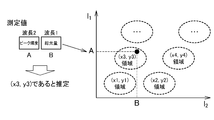
- the estimation unit 30 obtains the correct data group from the storage unit 20, creates the scatter diagram shown in FIG. 5, and as shown in FIG. 6, the measured amount I 1 of “peak brightness” and the measured amount of “total light amount”. Based on I 2 , two unknown parameters, here, the respective grain sizes (x, y) of the upper and lower layers are estimated from the plausible region in the scatter plot.
- the monitoring device 1 may further have the following configuration.
- the storage unit 20 stores various correct data groups for various parameters (x 1 , y 1 ), (x 2 , y 2 ),.
- a wavelength 1 as a measurement condition 1
- a wavelength 2 as a measurement condition 2
- a polarization as a measurement condition 3
- a measurement amount group (“peak brightness”, “total “Light intensity”, “skewness”?”
- the estimation unit 30 obtains the correct answer data group from the storage unit 20 based on the items of the measurement condition and the measurement amount, creates a scatter diagram, and based on the measurement amount I 1 and the measurement amount I 2 under the measurement condition. , Estimate the correct values for the two unknown parameters (x, y) from the plausible region in the scatter plot.
- the observation unit 10 has a response characteristic with respect to various measurement conditions, that is, a plurality of response characteristics with respect to electromagnetic waves (laser light here) having different properties and a plurality of different types. Get the response characteristics of.
- the estimation unit 30 creates a scatter diagram corresponding to each, and estimates an unknown parameter from the scatter diagram.
- the state of each layer of the deposit 2 multilayered on the road surface or runway for example, the size (eg, volume, area, thickness, etc.) of each layer, the physical properties of the deposit 2 (eg, particle size, It is possible to monitor the shape (for example, shape) and the type of material that constitutes the deposit 2 (for example, snow, ice, water, mud, volcanic ash, etc.).
- the unknown parameter is estimated using the scatter diagram, but in the second embodiment, the unknown parameter is estimated by pattern matching.
- the monitoring device 1 acquires data under a certain measurement condition for various combinations of two unknown parameters (x, y) to be measured.
- two-dimensional scatter images (see FIG. 3) of a certain wavelength are acquired for various combinations of particle sizes of the two-layer snow deposits 2 having different particle sizes, and the images are stored as a correct answer and learned. It is stored in the unit 20.
- the storage unit 20 stores a plurality of wavelengths ( ⁇ 1 , ⁇ ) for a combination of particle diameters ((x 1 , y 1 ), (x 2 , y 2 ),... ). 2 ).
- Each two-dimensional scattering image is stored.
- the estimation unit 30 when the estimation unit 30 obtains two two-dimensional scattering images, which are two pieces of data under two certain measurement conditions, for example, the wavelengths ⁇ 1 and ⁇ 2 as the measurement conditions, they are machine-learned.
- the unknown parameter (x, y) is identified by a device (for example, pattern matching by image identification).
- identification may be performed based on a feature amount obtained from data such as a two-dimensional scattering image, for example, peak brightness, kurtosis, total light amount and the like.
- data such as a two-dimensional scattering image
- the storage unit 20 stores, as correct value data, a table of feature amounts, for example, (x 1 , y 1 ), (x 2 , y 2 ),... 1 , ⁇ 2 ).
- a feature amount obtained from the two-dimensional scattered image, for example, peak brightness, kurtosis, and total light amount is stored in advance.
- the estimation unit 30 obtains, for example, peak brightness, kurtosis, and total light amount as feature amounts from one measurement condition, for example, one two-dimensional scattering image obtained at the wavelength ⁇ 1 , and The plausible unknown parameter is estimated from the matching between the table and the feature amount.
- the monitoring device 1 As described above, in the monitoring device 1 according to the second embodiment, it is possible to monitor the state of each layer of the multilayered deposit 2 by pattern matching.
- the monitoring device 1 estimates unknown parameters by a simultaneous equation-based solution method. As described above, at least two measurement quantities I 1 and I 2 are necessary for estimating the two unknown parameters (x, y) by the simultaneous equation-based solution method.
- the condition is that the relational expression between the unknown parameter and the measured amount and the theoretical expression are known.
- the storage unit 20 is a relational expression or a theoretical expression between the unknown parameters (x, y) and the measured quantities I 1 and I 2 .
- I 1 f(x,y)
- I 2 g(x,y)
- Estimation unit 30 as shown in FIG. 11, the measured quantity I 1 from the observation results obtained from the monitoring unit 10, I 2, for example, to obtain a peak intensity relative to the peak intensity and wavelength lambda 2 for the wavelength lambda 1, measurement of their
- the unknown parameters (x, y) are estimated by simultaneously solving the above-mentioned functions f and g which are unknown parameters (x, y) for the quantities I 1 and I 2, respectively.
- the state of each layer of the deposit 2 multilayered by the simultaneous equation solving method for example, the grain size of each upper and lower layer, the thickness of each upper and lower layer, etc. Can be monitored.
- the state of each layer of the multi-layered deposit is estimated and monitored by any method of the scatter diagram, pattern matching, or simultaneous equation-like solution, but the monitoring device according to the present invention , A scatter plot, pattern matching, simultaneous equation-like solution methods, and the like, and a means for selecting one of the methods according to predetermined conditions such as unknown parameters and measured quantities. You may have.
- the monitoring device according to the present invention has a configuration that realizes a plurality of methods among methods such as a scatter diagram, pattern matching, and simultaneous equation solving methods, and obtains an estimated value from each method. It is also possible to obtain an estimated value from a means for selecting a unique value or each method, and obtain a unique or wide estimated value from a plurality of estimated values by, for example, a statistical method.
- the wavelength and polarization are used as the measurement conditions, and the peak brightness, the total light amount, and the skewness are used as the measurement amounts.
- other measurement conditions and other measurement amounts may be used in the present invention. For example, by changing the position or orientation of the transmitting unit 11 or the receiving unit 12, the irradiation angle of the laser light, the irradiation position, the incident angle, the incident position, etc. are changed to obtain at least two response characteristics. Good.
- the state of each layer of the multi-layered deposit is monitored, but the monitoring device according to the present invention has a plurality of types of substances even if a plurality of types of substances are mixed in one layer.
- the state of the substance can be monitored.
- the monitoring device according to the present invention can monitor the quality of snow, the amount of mud, and the like when mud is mixed in snow, for example.
- the monitoring device according to the present invention may be configured to monitor the state of each layer of the multi-layered deposit and the state of each of a plurality of types of substances in each layer.
- the display unit 40 displays the estimation result by the estimation unit 30, but the monitoring device according to the present invention has a unit that converts the estimation result by the estimation unit 30 into a predetermined physical quantity.
- the converted physical quantity may be displayed on the display unit 40.
- the predetermined physical quantity is, for example, the quality of the deposit 2, the friction coefficient of the deposit 2, or the like.
- the laser light is used as the electromagnetic wave, but the present invention is not limited to the laser light, and any electromagnetic wave may be used.
- the electromagnetic wave is transmitted from the transmission unit 11 toward the deposit 2 and the scattered light reflected by the deposit 2 and scattered by the reception unit 12 is received.
- An electromagnetic wave may be transmitted toward the object 2 and the scattered light transmitted through the deposit 2 may be received by the receiving unit 12.
- the present invention can be applied to road management in the transportation field and runway management in the aviation field.
- layering of road surface deposits over time accumulation of snow with different snow quality, snow accumulation on ice film, etc.
- mixture water mixing due to rainfall, volcanic ash
- the present invention is also effective in grasping the multi-layered/mixed state of snow, water, sand, and volcanic ash on the airport runway surface in the aviation field.
- Real-time understanding of conditions such as the slipperiness of the runway can be used to determine whether or not the aircraft can take off and land, and whether snow removal on the runway is necessary. As a result, it is possible to prevent overrun accidents, flight delays and cancellations due to snow, so that it is possible to improve flight safety and flight efficiency.
Landscapes
- Physics & Mathematics (AREA)
- General Physics & Mathematics (AREA)
- Immunology (AREA)
- Pathology (AREA)
- Chemical & Material Sciences (AREA)
- Analytical Chemistry (AREA)
- Biochemistry (AREA)
- General Health & Medical Sciences (AREA)
- Health & Medical Sciences (AREA)
- Life Sciences & Earth Sciences (AREA)
- Engineering & Computer Science (AREA)
- Mathematical Physics (AREA)
- Theoretical Computer Science (AREA)
- Spectroscopy & Molecular Physics (AREA)
- Investigating Or Analysing Materials By Optical Means (AREA)
- Length Measuring Devices By Optical Means (AREA)
Abstract
【課題】多層化又は混合物化した堆積物の状態をモニタリングすること。 【解決手段】モニタリング装置1は、堆積物2に電磁波を照射し、堆積物2から得られる電磁波の応答特性を観測する観測部10と、観測部10の観測結果から、第1の性質の電磁波に対する前記応答特性、第2の性質の電磁波に対する前記応答特性、第1の種類の前記応答特性及び第2の種類の応答特性のうち少なくとも2つを得て、得られた少なくとも2つの応答特性に基づき、多層化又は混合物化した堆積物2を構成する複数の物の状態を推定する推定部30とを有する。
Description
本発明は、例えば路面や構造物の多層化又は混合物化した堆積物の状態をモニタリングするモニタリング装置及びモニタリング方法に関する。
道路面や滑走路面の着雪状態や着氷状態をモニタリングすることは、安全管理上重要である。特許文献1及び2には、透過電磁波や散乱電磁波を利用して積雪した雪の深さや質などをモニタリングする技術が記載されている。
特許文献1、2に記載された技術は、雪などの堆積物一層をモニタリングの対象としているが、実際には一層のみならず異なる種類の雪、或いは雪に加えて氷膜などの複数種類の堆積物が多層化する場合がある。また、積雪中に水や泥が混入するように、一層の場合でも複数種類の物質が混在している場合もある。実運用を想定すればモニタリング装置がそのような堆積物が多層化又は混合物化したケースに対応することは重要である。
以上のような事情に鑑み、本発明の目的は、多層化又は混合物化した堆積物の状態をモニタリングすることができるモニタリング装置及びモニタリング方法を提供することにある。
上記目的を達成するため、本発明の一形態に係るモニタリング装置は、堆積物に電磁波を照射し、前記堆積物から得られる前記電磁波の応答特性を観測する観測部と、前記観測部の観測結果から、第1の性質の電磁波に対する前記応答特性、第2の性質の電磁波に対する前記応答特性、第1の種類の前記応答特性及び第2の種類の前記応答特性のうち少なくとも2つを得て、得られた少なくとも2つの前記応答特性に基づき、多層化又は混合物化した前記堆積物を構成する複数の物の状態を推定する推定部とを具備する。
典型的には、前記第1の性質の電磁波に対する前記応答特性、前記第2の性質の電磁波に対する前記応答特性は、波長の異なる二種類のレーザ光や偏光の異なるレーザ光の照射による応答特性であり、また、異なる種類の応答特性である散乱光の「総光量」及び「ピーク輝度」の応答特性である。
典型的には、前記第1の性質の電磁波に対する前記応答特性、前記第2の性質の電磁波に対する前記応答特性は、波長の異なる二種類のレーザ光や偏光の異なるレーザ光の照射による応答特性であり、また、異なる種類の応答特性である散乱光の「総光量」及び「ピーク輝度」の応答特性である。
本発明の一形態に係るモニタリング装置では、典型的には、多層化又は混合物化した堆積物においてn個の未知のパラメータ、すなわち堆積物を構成する複数の物の状態を推定するため、観測部から被測定物としての堆積物からの電磁気学的な応答特性(例えば、光散乱強度や光透過強度等)を得る。ここで、nは自然数とする。次に、観測部での電磁波の性質(例えば、電磁波の波長や偏光等)を変更する、或いは応答特性の種類(例えば、光散乱強度、光透過強度等)を変更する、またはその両方を行い、n個のパラメータを推定するために必要な測定量としての少なくとも2つの応答特性を得る。次に、少なくとも2つの応答特性に基づき多層化又は混合物化した堆積物を構成する複数の物の状態を推定する。
本発明の一形態に係るモニタリング装置では、前記推定部は、前記多層化又は混合物化した堆積物を構成する複数の物の状態と少なくとも2つの前記応答特性との関係のデータから得られる、前記応答特性を座標軸とし前記物の状態の散布を示す散布図と前記観測部から得られた少なくとも2つの前記応答特性との関係から、前記多層化又は混合物化した堆積物を構成する複数の物の状態を推定してもよい。
本発明の一形態に係るモニタリング装置では、前記多層化又は混合物化した堆積物を構成する複数の物の状態と第1の性質の電磁波に対する前記応答特性、第2の性質の電磁波に対する前記応答特性との関係のデータを蓄積する記憶部を有し、前記推定部は、前記記憶部に蓄積されたデータの前記応答特性と前記観測部から得られた少なくとも2つの前記応答特性とのパターンマッチングにより、前記多層化又は混合物化した堆積物を構成する複数の物の状態を推定してもよい。パターンマッチングの態様としては、前記推定部が、前記記憶部に蓄積されたデータの前記応答特性としての二次元散乱画像と前記観測部から得られた少なくとも2つの前記応答特性としての二次元散乱画像とのパターンマッチングにより、前記多層化又は混合物化した堆積物を構成する複数の物の状態を推定してもよく、
前記推定部が、前記記憶部に蓄積されたデータの前記応答特性としての二次元散乱画像から得られる特徴量と前記観測部から得られた少なくとも2つの前記応答特性としての二次元散乱画像から得られる特徴量とのパターンマッチングにより、前記多層化又は混合物化した堆積物を構成する複数の物の状態を推定してもよい。
前記推定部が、前記記憶部に蓄積されたデータの前記応答特性としての二次元散乱画像から得られる特徴量と前記観測部から得られた少なくとも2つの前記応答特性としての二次元散乱画像から得られる特徴量とのパターンマッチングにより、前記多層化又は混合物化した堆積物を構成する複数の物の状態を推定してもよい。
本発明の一形態に係るモニタリング装置では、前記推定部は、前記多層化又は混合物化した堆積物を構成する複数の物の状態と前記観測部から得られる少なくとも2つの前記応答特性との相関を示す2つ以上の式に、前記観測部から得られた少なくとも2つの前記応答特性を代入し、これらの式を連立させて解くことで、前記多層化又は混合物化した堆積物を構成する複数の物の状態を推定してもよい。
本発明の一形態に係るモニタリング方法は、堆積物に電磁波を照射し、前記堆積物から得られる前記電磁波の応答特性を観測し、前記観測結果から、第1の性質の電磁波に対する前記応答特性、第2の性質の電磁波に対する前記応答特性、第1の種類の前記応答特性及び第2の種類の応答特性のうち少なくとも2つを得て、得られた少なくとも2つの前記応答特性に基づき、多層化又は混合物化した前記堆積物を構成する複数の物の状態を推定する。
本発明により、多層化又は混合物化した堆積物の状態をモニタリングすることができる。
以下、図面を参照しながら、本発明の実施形態を説明する。
<第1の実施形態>
(モニタリング装置の構成)
図1は第1の実施形態に係るモニタリング装置の構成を示す図である。
図1に示すように、モニタリング装置1は、観測部10と、記憶部20と、推定部30と、表示部40とを有する。
観測部10は、送信ユニット11と、受信ユニット12と、制御部13とを有し、例えば送信ユニット11及び受信ユニット12は、筐体50内に配置される。
図1は第1の実施形態に係るモニタリング装置の構成を示す図である。
図1に示すように、モニタリング装置1は、観測部10と、記憶部20と、推定部30と、表示部40とを有する。
観測部10は、送信ユニット11と、受信ユニット12と、制御部13とを有し、例えば送信ユニット11及び受信ユニット12は、筐体50内に配置される。
筐体50の上部には、透明部材からなる窓部51を有する。堆積物2は、筐体50の上部に堆積する。モニタリング装置1は、典型的には、路面や滑走路の下に埋め込まれ、窓部51が路面や滑走路と同一の面にあり、路面や滑走路に積雪した雪などの堆積物2をモニタリングする。
送信ユニット11は、窓部51を介して堆積物2に向けて電磁波としてレーザ光を送信するレーザ光源を有する。送信ユニット11は、例えば、波長の異なる二種類のレーザ光や偏光の異なるレーザ光を照射するように構成されている。
受信ユニット12は、窓部51を介して堆積物2で散乱したレーザ光の散乱光を受光する。受信ユニット12は、堆積物2で散乱した散乱光を受光するためのCCD(Charge Coupled Device)からなる二次元光学センサを有する。受信ユニット12は、特定の波長を受光し、特定の偏光したレーザ光を受光するためのフィルタなどを有する。
制御部13は、送信ユニット11よりレーザ光を送信させ、受信ユニット12に当該レーザ光に対する散乱光を受信させる。制御部13は、例えば、送信ユニット11より例えば波長の異なる二種類のレーザ光や偏光の異なるレーザ光を照射するように制御する。また、制御部13は、例えば、受信ユニット12が特定の波長を受光し、特定の偏光したレーザ光を受光するように制御する。
なお、後述する応答特性としての、例えば「総光量」と「ピーク輝度」は、観測部10において取得してもよいが、推定部30において受信ユニット12からのデータを基に取得してもよい。
受信ユニット12は、窓部51を介して堆積物2で散乱したレーザ光の散乱光を受光する。受信ユニット12は、堆積物2で散乱した散乱光を受光するためのCCD(Charge Coupled Device)からなる二次元光学センサを有する。受信ユニット12は、特定の波長を受光し、特定の偏光したレーザ光を受光するためのフィルタなどを有する。
制御部13は、送信ユニット11よりレーザ光を送信させ、受信ユニット12に当該レーザ光に対する散乱光を受信させる。制御部13は、例えば、送信ユニット11より例えば波長の異なる二種類のレーザ光や偏光の異なるレーザ光を照射するように制御する。また、制御部13は、例えば、受信ユニット12が特定の波長を受光し、特定の偏光したレーザ光を受光するように制御する。
なお、後述する応答特性としての、例えば「総光量」と「ピーク輝度」は、観測部10において取得してもよいが、推定部30において受信ユニット12からのデータを基に取得してもよい。
記憶部20は、後述する正解データ群を記憶する。
推定部30は、正解データ群から散布図を作成し、散布図から堆積物2の未知のパラメータを推定する。
なお、推定部30が正解データか群ら散布図を作成しているが、記憶部20が散布図を予め記憶していてもよい。
なお、推定部30が正解データか群ら散布図を作成しているが、記憶部20が散布図を予め記憶していてもよい。
表示部40は、推定部30による推定結果を表示する。
(実験結果)
ここで、本発明者らが多層化した堆積物をモニタリングできることを示すために行った実験結果を示す。
ここで、本発明者らが多層化した堆積物をモニタリングできることを示すために行った実験結果を示す。
まず、図2に示すように粒径の異なる雪のサンプルを用いて二層の堆積物2を作成し、試作した観測部10によって二次元光散乱画像を取得した。厚さを統一させた一層のデータと二層のデータを比較した。第1の実施形態では2次元光散乱画像から粒径の推定のプロセスを定量的に評価してはいないが、2つの異なる種類の応答特性である散乱光の「総光量」及び「ピーク輝度」による粒径の推定の可能性を、「総光量」及び「ピーク輝度」をそれぞれ座標軸とする散布図を用いて考察した。
散乱光の「総光量」とは、典型的には、2次元光散乱画像全体の光量の総計であり、散乱光の「ピーク輝度」とは、典型的には、2次元光散乱画像内で観測される最も大きな輝度である。
散乱光の「総光量」とは、典型的には、2次元光散乱画像全体の光量の総計であり、散乱光の「ピーク輝度」とは、典型的には、2次元光散乱画像内で観測される最も大きな輝度である。
実験は-5℃に調温された実験室内で行った。透過部材101(窓部51に相当)が底面に付属した厚さ5mmの観測試料ケース102及び二層化のため厚さ5mmの外枠103を準備した。観測試料ケース102と外枠103を組み合わせることで厚さ10mmの二層観測試料ケース100を作成した。サンプルとして粒径の異なる雪A(粒径0.5mm以下)及び雪B(粒径2.0-2.8mm)を準備し、それらの組み合わせを変えて4通りの二層化雪サンプル110を作成した。二層化雪サンプル110は、観測試料ケース102に下層(透過部材101に近い側)の雪を詰めて厚さを均一にならしたのちに、外枠103を観測試料ケース102にはめ、そこに上層の雪を詰めて厚さを均一にならすことで作成した。
二層雪の観測には観測部10を用いた。レーザ光源を有する送信ユニット11を用いて、透過部材101の下部から二層化雪サンプル110に向けて斜めに照射した。その散乱波を透過部材101の下部に鉛直に設置された受信ユニット12によって検知した。受信ユニット12としてはCMOSカメラが用い、二層化雪サンプル110からの散乱波を二次元光散乱分布として検出した。
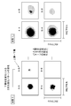
この構成により取得した4通りの二層化雪サンプル110からの2次元光散乱強度分布の観測結果が図3に示すとおりである。ここでは、送信ユニット11のレーザ光源において異なる二つの波長λ1、λ2を用いて2次元光散乱強度分布を取得している。
図3における例えばA-Bという表示は上層が雪Aであり下層が雪Bであるということに対応している。下層が送信ユニット11及び受信ユニット12に近い側と定義される。粒径の違いにより散乱波の量や角度が異なるために、2次元光散乱パターンが変化していることがわかる。先行研究などでは粒径が大きいほど光散乱強度が減少するということが知られており、その傾向に従った観測結果が得られると予想した。実際の観測結果では、下層の状態により光散乱強度が支配的に変化し、粒径が大きい雪ほど光散乱強度は減少していることがわかった。
また、図3において同一の下層の状態においても上層の状態が変化すれば光散乱強度が変化していることがわかり、同じく粒径が大きいほど光散乱強度は減少していた。例えば、A-Bの方がB-Bに比べて光散乱強度が大きくなっていることから、上層の粒径に応じて光散乱強度量が変化していることがわかる。
従って、応答特性の種類(例えば「総光量」と「ピーク輝度」)を変えて、或いは電磁波であるレーザ光の性質(例えば異なる二つの波長λ1、λ2)を変えてデータを取得し、パターンマッチングなどにかけることで、2層の状態を推定できる、と予想される。
図3における例えばA-Bという表示は上層が雪Aであり下層が雪Bであるということに対応している。下層が送信ユニット11及び受信ユニット12に近い側と定義される。粒径の違いにより散乱波の量や角度が異なるために、2次元光散乱パターンが変化していることがわかる。先行研究などでは粒径が大きいほど光散乱強度が減少するということが知られており、その傾向に従った観測結果が得られると予想した。実際の観測結果では、下層の状態により光散乱強度が支配的に変化し、粒径が大きい雪ほど光散乱強度は減少していることがわかった。
また、図3において同一の下層の状態においても上層の状態が変化すれば光散乱強度が変化していることがわかり、同じく粒径が大きいほど光散乱強度は減少していた。例えば、A-Bの方がB-Bに比べて光散乱強度が大きくなっていることから、上層の粒径に応じて光散乱強度量が変化していることがわかる。
従って、応答特性の種類(例えば「総光量」と「ピーク輝度」)を変えて、或いは電磁波であるレーザ光の性質(例えば異なる二つの波長λ1、λ2)を変えてデータを取得し、パターンマッチングなどにかけることで、2層の状態を推定できる、と予想される。
次に、2次元光散乱画像から2つ種類の異なる応答特性(「総光量」と「ピーク輝度」)の観測量を得て、それを相対的に他の層状態と比較することで、「総光量」及び「ピーク輝度」をそれぞれ座標軸とする散布図を用いて上層・下層の粒径を推定できることを説明する。
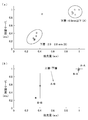
図3に示したような波長λ1における4通りの2次元光散乱画像から「総光量」及び「ピーク輝度」をそれぞれ座標軸とする散布図を作成した。その結果を図4(a)に示す。ここでは、4通りの2層状態各々に対して3回測定を行ったためデータ点は12個となっており、データの最大値に対してすべてのデータが規格化されている。図4(a)にも示したとおり、下層状態の変化は「ピーク輝度」及び「総光量」双方に大きく依存するため、散布図上にある閾値を設けたグルーピングによって下層の粒径は把握することが可能である。傾向としては粒径の減少に伴い光散乱強度は単調増加するために、「ピーク輝度」及び「総光量」は単調増加する。図4(a)の測定値にばらつきや外れ値が混じっているために、まず同条件の測定に関しては平均及び標準偏差を導出して、改めて図4(b)に示すようにプロットした。図4(b)より下層の変化ほど顕著ではないものの、上層の粒径の状態に光散乱が影響しており、粒径の減少に伴い「ピーク輝度」及び「総光量」は単調増加している傾向がわかる。これによって上層も同様にグルーピング可能であると考えられる。また、複数の物の状態の一形態としての多層化した堆積物の各層の状態をモニタリングするために、2つの応答特性として「ピーク輝度」及び「総光量」を用いて検討したが、電磁波であるレーザ光の性質(例えば異なる二つの波長λ1、λ2)を変えて、各波長λ1、λ2のそれぞれの応答特性である例えばピーク輝度等について、波長λ1のピーク輝度と波長λ1のピーク輝度とを座標軸とする散布図を作成することによって上層・下層の粒径の推定も可能であると考えられる。すなわち、異なる性質の電磁波(例えば異なる二つの波長λ1、λ2)に対する複数の応答特性又は異なる種類の複数の応答特性(例えば「ピーク輝度」と「総光量」)のうち少なくとも一方を得て、得られた少なくとも2つの応答特性に基づき堆積物を構成する複数の物の状態を推定することは可能であると考えられる。
図3に示したような波長λ1における4通りの2次元光散乱画像から「総光量」及び「ピーク輝度」をそれぞれ座標軸とする散布図を作成した。その結果を図4(a)に示す。ここでは、4通りの2層状態各々に対して3回測定を行ったためデータ点は12個となっており、データの最大値に対してすべてのデータが規格化されている。図4(a)にも示したとおり、下層状態の変化は「ピーク輝度」及び「総光量」双方に大きく依存するため、散布図上にある閾値を設けたグルーピングによって下層の粒径は把握することが可能である。傾向としては粒径の減少に伴い光散乱強度は単調増加するために、「ピーク輝度」及び「総光量」は単調増加する。図4(a)の測定値にばらつきや外れ値が混じっているために、まず同条件の測定に関しては平均及び標準偏差を導出して、改めて図4(b)に示すようにプロットした。図4(b)より下層の変化ほど顕著ではないものの、上層の粒径の状態に光散乱が影響しており、粒径の減少に伴い「ピーク輝度」及び「総光量」は単調増加している傾向がわかる。これによって上層も同様にグルーピング可能であると考えられる。また、複数の物の状態の一形態としての多層化した堆積物の各層の状態をモニタリングするために、2つの応答特性として「ピーク輝度」及び「総光量」を用いて検討したが、電磁波であるレーザ光の性質(例えば異なる二つの波長λ1、λ2)を変えて、各波長λ1、λ2のそれぞれの応答特性である例えばピーク輝度等について、波長λ1のピーク輝度と波長λ1のピーク輝度とを座標軸とする散布図を作成することによって上層・下層の粒径の推定も可能であると考えられる。すなわち、異なる性質の電磁波(例えば異なる二つの波長λ1、λ2)に対する複数の応答特性又は異なる種類の複数の応答特性(例えば「ピーク輝度」と「総光量」)のうち少なくとも一方を得て、得られた少なくとも2つの応答特性に基づき堆積物を構成する複数の物の状態を推定することは可能であると考えられる。
(モニタリング装置の推定処理)
本実施形態に係るモニタリング装置1は以下のとおり推定処理を実行する。
本実施形態に係るモニタリング装置1は以下のとおり推定処理を実行する。
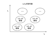
記憶部20は、例えば図5に示す散布図を構成するための正解データ群を予め記憶しておく。図5に示す散布図は例えば図4(a)に示した「ピーク輝度」I1と「総光量」I2とをそれぞれ座標軸とし、様々な条件(例えば、雪の粒径や深さなど)で測定した結果、つまり正解データがプロットされている。
推定部30は、記憶部20から正解データ群を得て、図5に示す散布図を作成し、図6に示すように、「ピーク輝度」の測定量I1及び「総光量」の測定量I2をもとにして、散布図におけるもっともらしい領域から、2つの未知パラメータ、ここでは上下層の各粒径(x,y)を推定する。
以上の説明は、二つの未知のパラメータである下層の粒径及び上層の粒径に対する正解データとして「ピーク輝度」と「総光量」とをそれぞれ座標軸とする散布図を例示したが、本実施形態に係るモニタリング装置1は、更に以下のような構成を採用してもよい。
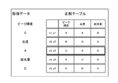
図7に示すように、記憶部20は、様々なパラメータ(x1,y1)、(x2,y2)、・・・に対する様々な正解データ群を記憶されている。例えば、測定条件1として波長1、測定条件2として波長2、測定条件3として偏光・・・があり、各測定条件1,2・・・に対して測定量群(「ピーク輝度」、「総光量」、「歪度」・・・)が記憶されている。
推定部30は、測定条件及び測定量の項目に基づき記憶部20から正解データ群を得て、散布図を作成し、その測定条件での測定量I1及び測定量I2をもとにして、散布図におけるもっともらしい領域から、2つの未知パラメータ(x,y)に対する正解値を推定する。
以上のように、第1の実施形態に係るモニタリング装置1では、観測部10で様々な測定条件に対する応答特性、すなわち異なる性質の電磁波(ここではレーザ光)に対する複数の応答特性や異なる種類の複数の応答特性を得る。次に、推定部30においてそれぞれに対応する散布図を作成し、そこから未知のパラメータを推定する。これにより、路面や滑走路等に多層化した堆積物2の各層の状態、例えば各層を構成する大きさ(例えば、体積や面積、厚さなど)、堆積物2の物性(例えば、粒径や形など)や堆積物2を構成する物の種類(例えば、雪・氷・水・泥・火山灰など)等をモニタリングすることができる。
<第2の実施形態>
第1の実施形態では、散布図を用いて未知のパラメータを推定していたが、第2の実施形態では、パターンマッチングにより未知のパラメータを推定する。
第1の実施形態では、散布図を用いて未知のパラメータを推定していたが、第2の実施形態では、パターンマッチングにより未知のパラメータを推定する。
第2の実施形態に係るモニタリング装置1では、測定したい2つの未知のパラメータ(x,y)の様々な組み合わせに対して、ある測定条件におけるデータを取得する。例えば、粒径の異なる二層の雪の堆積物2の様々な粒径の組み合わせに対するある波長の二次元散乱画像(図3参照)をそれぞれ取得し、これを正解として学習させてデータセットを記憶部20に蓄積させる。これにより、記憶部20は、図8に示すように、例えば粒径の組み合わせ((x1,y1)、(x2,y2)、・・・)に対する複数の波長(λ1、λ2・・・)の各二次元散乱画像を記憶する。
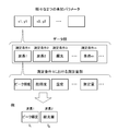
推定部30は、図9に示すように、2つのある測定条件、例えば測定条件として波長λ1、λ2においてそれぞれ2つのデータである2つの二次元散乱画像を得たとき、それを機械学習器(例えば画像識別によるパターンマッチング)などにより未知のパラメータ(x,y)を同定する。
本実施形態に係るモニタリング装置1では、二次元散乱画像などのデータから求められる特徴量、例えばピーク輝度、尖度、総光量などを基にして同定してもよい。
例えば、図8に示したように、記憶部20は、正解値のデータとして特徴量のテーブル、例えば(x1,y1)、(x2,y2)、・・・に対する各波長(λ1、λ2・・・)の二次元散乱画像から得られる特徴量、例えばピーク輝度、尖度、総光量を予め記憶しておく。
例えば、図8に示したように、記憶部20は、正解値のデータとして特徴量のテーブル、例えば(x1,y1)、(x2,y2)、・・・に対する各波長(λ1、λ2・・・)の二次元散乱画像から得られる特徴量、例えばピーク輝度、尖度、総光量を予め記憶しておく。
推定部30は、図10に示すように、1つの測定条件、例えば波長λ1で得られた1つの二次元散乱画像から特徴量として例えばピーク輝度、尖度及び総光量を得て、上記のテーブルと特徴量とのマッチングからもっともらしい未知パラメータを推定する。
以上のように、第2の実施形態に係るモニタリング装置1においては、パターンマッチングにより多層化した堆積物2の各層の状態をモニタリングすることができる。
<第3の実施形態>
測定したいパラメータと測定量との関係式や理論式が既知である場合には、連立方程式的解法によって測定したいパラメータである未知のパラメータ(x,y)を推定することが可能である。
測定したいパラメータと測定量との関係式や理論式が既知である場合には、連立方程式的解法によって測定したいパラメータである未知のパラメータ(x,y)を推定することが可能である。
第3の実施形態に係るモニタリング装置1は、連立方程式的解法によって未知のパラメータを推定する。上記のとおり、連立方程式的解法による2つの未知パラメータ(x,y)の推定には少なくとも2つの測定量I1、I2が必要である。また、未知のパラメータと測定量との関係式や理論式が既知であることが条件である。
記憶部20は、未知のパラメータ(x,y)と測定量I1、I2との関係式又は理論式である、
I1=f(x,y)
I2=g(x,y)
を記憶する。
I1=f(x,y)
I2=g(x,y)
を記憶する。
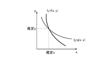
推定部30は、図11に示すように、観測部10より得た観測結果から測定量I1、I2、例えば波長λ1に対するピーク輝度及び波長λ2に対するピーク輝度を得て、それらの測定量I1、I2それぞれに対して未知のパラメータ(x,y)とする上記の関数f、gを連立させて解くことで、未知のパラメータ(x,y)を推定する。
ここで、図12に示すように、関数f、gがx-y座標上の一点で交差する場合には、推定される(x,y)が一意に決まるが、推定される(x,y)が一意に決まらないケース(図13参照)や解が存在しないケース(図14参照)が考えられる。これらは測定量が2つでは推定しきれないとされるケースである。
これらの場合には、以下の手法を採用すればよい。
・得られた結果から一番もっともらしい推定値を選ぶ。
・測定量を増やし推定値を追い込む。
・測定量I1又はI2を棄却して新しい測定量を採用し、再度連立させて推定する。
これらの場合には、以下の手法を採用すればよい。
・得られた結果から一番もっともらしい推定値を選ぶ。
・測定量を増やし推定値を追い込む。
・測定量I1又はI2を棄却して新しい測定量を採用し、再度連立させて推定する。
以上のように、第3の実施形態に係るモニタリング装置1においては、連立方程式的解法により多層化した堆積物2の各層の状態、例えば上下の各層の粒径、上下の各層の厚さ等をモニタリングすることができる。
<その他>
本発明は上記の実施形態には限定されず、本発明の技術思想の範囲内で変形や応用をして実施することが可能であり、その実施の範囲も本発明の技術的範囲に属する。
本発明は上記の実施形態には限定されず、本発明の技術思想の範囲内で変形や応用をして実施することが可能であり、その実施の範囲も本発明の技術的範囲に属する。
例えば、上記の実施形態では、散布図、パターンマッチング又は連立方程式的解法のいずれかの手法により多層化した堆積物の各層の状態を推定してモニタリングしていたが、本発明に係るモニタリング装置は、散布図、パターンマッチング、連立方程式的解法等の手法のうち複数の手法を実現する構成を有し、未知パラメータや測定量等の所定の条件に応じていずれかの手法を選択する手段を有していてもよい。また、本発明に係るモニタリング装置は、散布図、パターンマッチング、連立方程式的解法等の手法のうち複数の手法を実現する構成を有し、各手法から推定値を得て、例えば推定値からもっともらしい値を選択する手段、或いは各手法から推定値を得て、複数の推定値から例えば統計的手法により唯一の又は幅のある推定値を得てもよい。
上記の実施形態では、測定条件として波長や偏光、測定量としてピーク輝度、総光量、歪度を例示したが、本発明では他の測定条件や他の測定量を用いてもよい。例えば、送信ユニット11又は受信ユニット12の位置又は姿勢を変化させることで、レーザ光の照射角、照射位置、入射角、入射位置などを変更し、少なくとも2つの応答特性を得るように構成してもよい。
上記の実施形態では、多層化した堆積物の各層の状態をモニタリングしていたが、本発明に係るモニタリング装置は、一層に複数種類の物質が混在している状態であっても複数種類の各物質の状態をモニタリングすることができる。本発明に係るモニタリング装置は、例えば雪の中に泥が混在している場合に、雪の質や泥の量等をモニタリングすることができる。本発明に係るモニタリング装置は、多層化した堆積物の各層の状態をモニタリングし、且つ、各層の複数種類の各物質の状態をモニタリングするように構成してもよい。
上記の実施形態では、表示部40が推定部30による推定結果を表示するものであったが、本発明に係るモニタリング装置は、推定部30による推定結果から所定の物理量に換算する手段を有し、その換算された物理量を表示部40に表示するようにしてもよい。所定の物理量とは、例えば堆積物2の質やの摩擦係数等がある。
上記の実施形態では、電磁波としてレーザ光を用いていたが、本発明は、レーザ光に限定されず、電磁波であればいかなるものであってもよい。
上記の実施形態では、送信ユニット11から堆積物2に向けて電磁波を送信し、受信ユニット12により堆積物2で反射して散乱した散乱光を受光するように構成したが、送信ユニット11から堆積物2に向けて電磁波を送信し、堆積物2を透過した散乱光を受信ユニット12により受光するように構成してもよい。
本発明は、交通分野における道路管理や航空分野における滑走路管理等に応用することができる。
本発明を道路管理に応用することで、路面堆積物の時間経過による多層化(雪質の異なる雪の堆積・氷膜上への雪の堆積等)および混合物化(降雨による水の混入、火山灰・泥などの混入)を検知及び把握することが可能になる。それにより、堆積物表面を観測しただけではわからないような多層化・混合化状態の情報を用いて正確な路面の滑りやすさ把握などに役立てることができ、効率的な道路管理が可能になる。
また、本発明は航空分野における空港滑走路面の積雪・水・砂・火山灰の多層化・混合化状態の把握においても有効である。滑走路面の滑りやすさなどの状態のリアルタイム把握が、航空機の離着陸可否、滑走路の除雪の必要性判断に役立てることができる。それにより、積雪によるオーバーラン事故や運航遅延及び欠航を防ぐことができるため、運航安全性の向上及び運航効率性の向上を図ることができる。
本発明を道路管理に応用することで、路面堆積物の時間経過による多層化(雪質の異なる雪の堆積・氷膜上への雪の堆積等)および混合物化(降雨による水の混入、火山灰・泥などの混入)を検知及び把握することが可能になる。それにより、堆積物表面を観測しただけではわからないような多層化・混合化状態の情報を用いて正確な路面の滑りやすさ把握などに役立てることができ、効率的な道路管理が可能になる。
また、本発明は航空分野における空港滑走路面の積雪・水・砂・火山灰の多層化・混合化状態の把握においても有効である。滑走路面の滑りやすさなどの状態のリアルタイム把握が、航空機の離着陸可否、滑走路の除雪の必要性判断に役立てることができる。それにより、積雪によるオーバーラン事故や運航遅延及び欠航を防ぐことができるため、運航安全性の向上及び運航効率性の向上を図ることができる。
1 :モニタリング装置
2 :堆積物
10 :観測部
20 :記憶部
30 :推定部
2 :堆積物
10 :観測部
20 :記憶部
30 :推定部
Claims (8)
- 堆積物に電磁波を照射し、前記堆積物から得られる前記電磁波の応答特性を観測する観測部と、
前記観測部の観測結果から、第1の性質の電磁波に対する前記応答特性、第2の性質の電磁波に対する前記応答特性、第1の種類の前記応答特性及び第2の種類の前記応答特性のうち少なくとも2つを得て、得られた少なくとも2つの前記応答特性に基づき、多層化又は混合物化した前記堆積物を構成する複数の物の状態を推定する推定部と
を具備するモニタリング装置。 - 前記推定部は、前記多層化又は混合物化した堆積物を構成する複数の物の状態と少なくとも2つの前記応答特性との関係のデータから得られる、前記応答特性を座標軸とし前記物の状態の散布を示す散布図と前記観測部から得られた少なくとも2つの前記応答特性との関係から、前記多層化又は混合物化した堆積物を構成する複数の物の状態を推定する
請求項1に記載のモニタリング装置。 - 前記多層化又は混合物化した堆積物を構成する複数の物の状態と第1の性質の電磁波に対する前記応答特性、第2の性質の電磁波に対する前記応答特性との関係のデータを蓄積する記憶部を有し、
前記推定部は、前記記憶部に蓄積されたデータの前記応答特性と前記観測部から得られた少なくとも2つの前記応答特性とのパターンマッチングにより、前記多層化又は混合物化した堆積物を構成する複数の物の状態を推定する
請求項1に記載のモニタリング装置。 - 前記推定部は、前記記憶部に蓄積されたデータの前記応答特性としての二次元散乱画像と前記観測部から得られた少なくとも2つの前記応答特性としての二次元散乱画像とのパターンマッチングにより、前記多層化又は混合物化した堆積物を構成する複数の物の状態を推定する
請求項3に記載のモニタリング装置。 - 前記推定部は、前記記憶部に蓄積されたデータの前記応答特性としての二次元散乱画像から得られる特徴量と前記観測部から得られた少なくとも2つの前記応答特性としての二次元散乱画像から得られる特徴量とのパターンマッチングにより、前記多層化又は混合物化した堆積物を構成する複数の物の状態を推定する
請求項3に記載のモニタリング装置。 - 前記第1の性質の電磁波に対する前記応答特性、前記第2の性質の電磁波に対する前記応答特性は、波長の異なる二種類のレーザ光や偏光の異なるレーザ光の照射による応答特性であり、また、異なる種類の応答特性である散乱光の総光量及びピーク輝度の応答特性である、請求項1記載のモニタリング装置。
- 前記推定部は、前記多層化又は混合物化した堆積物を構成する複数の物の状態と前記観測部から得られる少なくとも2つの前記応答特性との相関を示す2つ以上の式に、前記観測部から得られた少なくとも2つの前記応答特性を代入し、これらの式を連立させて解くことで、前記多層化又は混合物化した堆積物を構成する複数の物の状態を推定する
請求項1に記載のモニタリング装置。 - 堆積物に電磁波を照射し、前記堆積物から得られる前記電磁波の応答特性を観測し、
前記観測結果から、第1の性質の電磁波に対する前記応答特性、第2の性質の電磁波に対する前記応答特性、第1の種類の前記応答特性及び第2の種類の応答特性のうち少なくとも2つを得て、得られた少なくとも2つの前記応答特性に基づき、多層化又は混合物化した前記堆積物を構成する複数の物の状態を推定する
モニタリング方法。
Applications Claiming Priority (2)
| Application Number | Priority Date | Filing Date | Title |
|---|---|---|---|
| JP2019029056A JP7320214B2 (ja) | 2019-02-21 | 2019-02-21 | モニタリング装置及びモニタリング方法 |
| JP2019-029056 | 2019-12-26 |
Publications (1)
| Publication Number | Publication Date |
|---|---|
| WO2020170815A1 true WO2020170815A1 (ja) | 2020-08-27 |
Family
ID=72144672
Family Applications (1)
| Application Number | Title | Priority Date | Filing Date |
|---|---|---|---|
| PCT/JP2020/004297 Ceased WO2020170815A1 (ja) | 2019-02-21 | 2020-02-05 | モニタリング装置及びモニタリング方法 |
Country Status (2)
| Country | Link |
|---|---|
| JP (1) | JP7320214B2 (ja) |
| WO (1) | WO2020170815A1 (ja) |
Families Citing this family (2)
| Publication number | Priority date | Publication date | Assignee | Title |
|---|---|---|---|---|
| JP7382038B2 (ja) * | 2019-11-28 | 2023-11-16 | 国立研究開発法人宇宙航空研究開発機構 | 情報処理システム、情報処理装置、情報処理方法、及びプログラム |
| JP7383247B2 (ja) * | 2019-11-28 | 2023-11-20 | 国立研究開発法人宇宙航空研究開発機構 | 情報処理システム、情報処理装置、情報処理方法、及びプログラム |
Citations (9)
| Publication number | Priority date | Publication date | Assignee | Title |
|---|---|---|---|---|
| JPH11500534A (ja) * | 1995-02-24 | 1999-01-12 | インスティテュート ファー ヒェモ ウント ビオゼンゾリック ミュンスター エー.ファー. | 路面、特に交通路の路面の状態を確認する方法、および、この方法を実施するための装置 |
| JP2005266014A (ja) * | 2004-03-16 | 2005-09-29 | Tokyo Institute Of Technology | 視覚障害者用画像認識装置、その方法及びプログラム |
| JP2008077349A (ja) * | 2006-09-20 | 2008-04-03 | Toyota Motor Corp | 車両状態量推定装置及びその装置を用いた車両操舵制御装置 |
| WO2012086070A1 (ja) * | 2010-12-24 | 2012-06-28 | 株式会社日立製作所 | 路面形状認識装置及びそれを利用した自律移動装置 |
| JP2015001379A (ja) * | 2013-06-13 | 2015-01-05 | 独立行政法人 宇宙航空研究開発機構 | 路面および構造物表面状況モニタリングセンサー |
| JP2015038516A (ja) * | 2014-11-27 | 2015-02-26 | 株式会社ブリヂストン | 路面状態推定方法 |
| JP2015148600A (ja) * | 2014-01-07 | 2015-08-20 | パナソニック インテレクチュアル プロパティ コーポレーション オブアメリカPanasonic Intellectual Property Corporation of America | 成分計測装置および移動体 |
| JP2016170069A (ja) * | 2015-03-13 | 2016-09-23 | 国立研究開発法人宇宙航空研究開発機構 | 雪氷モニタ装置 |
| JP2017165410A (ja) * | 2014-11-07 | 2017-09-21 | 大日本印刷株式会社 | 照明装置 |
Family Cites Families (2)
| Publication number | Priority date | Publication date | Assignee | Title |
|---|---|---|---|---|
| SE524878C2 (sv) | 2002-10-10 | 2004-10-19 | Ulf Elman | Anordning, metod och system för att bestämma en vägytas tillstånd med våglängdsmodulerad spektrometri |
| JP2006242891A (ja) | 2005-03-07 | 2006-09-14 | Tokyo Univ Of Agriculture & Technology | 土壌特性測定装置 |
-
2019
- 2019-02-21 JP JP2019029056A patent/JP7320214B2/ja active Active
-
2020
- 2020-02-05 WO PCT/JP2020/004297 patent/WO2020170815A1/ja not_active Ceased
Patent Citations (9)
| Publication number | Priority date | Publication date | Assignee | Title |
|---|---|---|---|---|
| JPH11500534A (ja) * | 1995-02-24 | 1999-01-12 | インスティテュート ファー ヒェモ ウント ビオゼンゾリック ミュンスター エー.ファー. | 路面、特に交通路の路面の状態を確認する方法、および、この方法を実施するための装置 |
| JP2005266014A (ja) * | 2004-03-16 | 2005-09-29 | Tokyo Institute Of Technology | 視覚障害者用画像認識装置、その方法及びプログラム |
| JP2008077349A (ja) * | 2006-09-20 | 2008-04-03 | Toyota Motor Corp | 車両状態量推定装置及びその装置を用いた車両操舵制御装置 |
| WO2012086070A1 (ja) * | 2010-12-24 | 2012-06-28 | 株式会社日立製作所 | 路面形状認識装置及びそれを利用した自律移動装置 |
| JP2015001379A (ja) * | 2013-06-13 | 2015-01-05 | 独立行政法人 宇宙航空研究開発機構 | 路面および構造物表面状況モニタリングセンサー |
| JP2015148600A (ja) * | 2014-01-07 | 2015-08-20 | パナソニック インテレクチュアル プロパティ コーポレーション オブアメリカPanasonic Intellectual Property Corporation of America | 成分計測装置および移動体 |
| JP2017165410A (ja) * | 2014-11-07 | 2017-09-21 | 大日本印刷株式会社 | 照明装置 |
| JP2015038516A (ja) * | 2014-11-27 | 2015-02-26 | 株式会社ブリヂストン | 路面状態推定方法 |
| JP2016170069A (ja) * | 2015-03-13 | 2016-09-23 | 国立研究開発法人宇宙航空研究開発機構 | 雪氷モニタ装置 |
Also Published As
| Publication number | Publication date |
|---|---|
| JP2020134347A (ja) | 2020-08-31 |
| JP7320214B2 (ja) | 2023-08-03 |
Similar Documents
| Publication | Publication Date | Title |
|---|---|---|
| US11624814B2 (en) | Remote measurement of shallow depths in semi-transparent media | |
| Bablet et al. | MARMIT: A multilayer radiative transfer model of soil reflectance to estimate surface soil moisture content in the solar domain (400–2500 nm) | |
| KR101922831B1 (ko) | 콘크리트 상태를 판정하는 영상분석장치 및 영상분석방법 | |
| WO2019082504A1 (ja) | 情報処理装置、情報処理方法、プログラム、及びモニタリングシステム | |
| WO2020170815A1 (ja) | モニタリング装置及びモニタリング方法 | |
| Campbell et al. | Radar polarization properties of volcanic and playa surfaces: Applications to terrestrial remote sensing and Venus data interpretation | |
| EP3155174B1 (de) | Steuerungsvorrichtung für ein streufahrzeug | |
| DE112015006168T5 (de) | Paralleles optisches Messsystem mit winkelselektiven Breitbandfiltern | |
| Shen et al. | Polarization imaging performances based on different retrieving Mueller matrixes | |
| WO2012038036A1 (de) | Vorrichtung und verfahren zur optischen charakterisierung von materialien | |
| Göbel et al. | Dependent scattering effects in latex-sphere suspensions and scattering powders | |
| EP2795288B1 (de) | Verfahren zum ermitteln einer partikeleigenschaft und zum klassifizieren einer partikelcharge sowie vorrichtung zum durchführen der verfahren | |
| van Der Laan et al. | Range and contrast imaging improvements using circularly polarized light in scattering environments | |
| TW200533909A (en) | Method and apparatus for void content measurement and method and apparatus for particle content measurement | |
| Haines et al. | Anisotropic resonant scattering from polymer photonic crystals | |
| Song et al. | The irradiating field of view of imaging laser radar under fog conditions in a controlled laboratory environment | |
| Kobus et al. | Radiative transfer simulations for in-situ particle size diagnostic in reactive, particle growing plasmas | |
| Henley et al. | Measurement of snowpack density, grain size, and black carbon concentration using time-domain diffuse optics | |
| DE102019214913A1 (de) | Bildgebungsvorrichtung | |
| JP2019082359A (ja) | モニタリング装置、及びモニタリングシステム | |
| Tamáska et al. | Color changes upon cooling of Lepidoptera scales containing photonic nanoarchitectures | |
| Albar et al. | Classification of intrusive igneous rocks using digital image processing: a binary approach | |
| Philbrick et al. | Optical remote sensing techniques characterize the properties of atmospheric aerosols | |
| Monga et al. | Analyzing the impact of fog on wireless propagation using different attenuation models | |
| Zhang et al. | Bi-directional reflectance measurements of closely packed natural and prepared particulate surfaces |
Legal Events
| Date | Code | Title | Description |
|---|---|---|---|
| 121 | Ep: the epo has been informed by wipo that ep was designated in this application |
Ref document number: 20758934 Country of ref document: EP Kind code of ref document: A1 |
|
| NENP | Non-entry into the national phase |
Ref country code: DE |
|
| 122 | Ep: pct application non-entry in european phase |
Ref document number: 20758934 Country of ref document: EP Kind code of ref document: A1 |