WO2020170727A1 - 細胞回収方法及び細胞回収装置 - Google Patents
細胞回収方法及び細胞回収装置 Download PDFInfo
- Publication number
- WO2020170727A1 WO2020170727A1 PCT/JP2020/002925 JP2020002925W WO2020170727A1 WO 2020170727 A1 WO2020170727 A1 WO 2020170727A1 JP 2020002925 W JP2020002925 W JP 2020002925W WO 2020170727 A1 WO2020170727 A1 WO 2020170727A1
- Authority
- WO
- WIPO (PCT)
- Prior art keywords
- culture container
- cells
- cell
- culture
- outer edge
- Prior art date
- Legal status (The legal status is an assumption and is not a legal conclusion. Google has not performed a legal analysis and makes no representation as to the accuracy of the status listed.)
- Ceased
Links
Images












Classifications
-
- C—CHEMISTRY; METALLURGY
- C12—BIOCHEMISTRY; BEER; SPIRITS; WINE; VINEGAR; MICROBIOLOGY; ENZYMOLOGY; MUTATION OR GENETIC ENGINEERING
- C12M—APPARATUS FOR ENZYMOLOGY OR MICROBIOLOGY; APPARATUS FOR CULTURING MICROORGANISMS FOR PRODUCING BIOMASS, FOR GROWING CELLS OR FOR OBTAINING FERMENTATION OR METABOLIC PRODUCTS, i.e. BIOREACTORS OR FERMENTERS
- C12M1/00—Apparatus for enzymology or microbiology
- C12M1/10—Apparatus for enzymology or microbiology rotatably mounted
-
- C—CHEMISTRY; METALLURGY
- C12—BIOCHEMISTRY; BEER; SPIRITS; WINE; VINEGAR; MICROBIOLOGY; ENZYMOLOGY; MUTATION OR GENETIC ENGINEERING
- C12N—MICROORGANISMS OR ENZYMES; COMPOSITIONS THEREOF; PROPAGATING, PRESERVING, OR MAINTAINING MICROORGANISMS; MUTATION OR GENETIC ENGINEERING; CULTURE MEDIA
- C12N5/00—Undifferentiated human, animal or plant cells, e.g. cell lines; Tissues; Cultivation or maintenance thereof; Culture media therefor
Definitions
- the disclosed technology relates to a cell recovery method and a cell recovery device.
- Japanese Unexamined Patent Publication No. 2010-148451 discloses that a side wall having a cylindrical surface and a plurality of recesses that are recessed outward in the radial direction at intervals in the circumferential direction are provided on the side wall to accommodate a cell suspension.
- a container body that is rotated around the central axis of the side wall, a cleaning liquid supply pipe that has a discharge port near the bottom of each recess of the container body, and a suction port that has a suction port facing the side wall between adjacent recesses.
- a tube With a tube.
- the cells are uniformly dispersed on the bottom surface of the culture container in order to make the quality of the cells uniform.
- the cells cultured in the culture container are recovered from the culture container, it is preferable to recover the cells in a short time from the viewpoint of suppressing damage to the cells and increasing the recovery rate of the cells.
- the cells uniformly dispersed on the bottom surface of the culture container are unevenly distributed at specific locations in the culture container.
- Centrifugation is one of the common methods to distribute cells.
- centrifugation using a centrifuge requires a dedicated container called a centrifuge tube, and it is difficult to use a culture container used for culturing cells.
- a centrifugal force of several hundred G generally acts for several minutes, which may damage cells.
- aggregates of cells are formed, oxygen supply to the cells at the central part of the aggregates becomes insufficient, and cell death may occur.
- the disclosed technology aims to collect cells from the culture container while suppressing damage to the cells.
- the cell recovery method includes rotating a culture container containing cells by rotating a culture container around a rotation axis that intersects with the bottom face of the culture container and rotating the bottom face of the culture container before or during rotation of the culture container. Discharging the liquid to the center, unevenly distributing the cells on the outer edge of the bottom surface of the culture container, and collecting the cells unevenly distributed on the outer edge of the bottom surface of the culture container.
- the cell recovery method it becomes possible to recover cells from the culture container while suppressing damage to the cells.
- the relative centrifugal force that acts on the outer edge of the bottom of the culture vessel is larger than the minimum size that allows cells to be unevenly distributed on the outer edge of the bottom of the culture vessel, and the maximum that does not cause the cells to pop out of the culture vessel. It is preferably smaller than the limit size. This makes it possible to make the cells unevenly distributed on the outer edge of the bottom surface of the culture container while suppressing the cells from jumping out of the culture container.
- cells are collected by sucking cells from a suction port arranged at a position corresponding to the outer edge of the bottom surface of the culture container while rotating the culture container around a rotation axis. You may. As a result, the relative position between the suction port and the culture container can be moved by rotating the culture container.
- the rotation axis of the culture container may be arranged at a position corresponding to the center of the bottom surface of the culture container. This promotes the movement of the bottom surface of the culture container to the outer edge portion.
- the bottom of the culture vessel may be provided with a plurality of recesses for accommodating cells.
- the size of the cell mass formed in the recess can be made substantially uniform between the recesses.
- the cell recovery device is arranged at a position corresponding to an outer peripheral portion of the bottom surface of the culture container and a rotation drive unit for rotating the culture container around a rotation axis intersecting the bottom surface of the culture container.
- a collection unit that collects cells stored in the culture container by suction from the suction port, and a liquid discharge unit that discharges liquid to the center of rotation of the bottom surface of the culture container are included.
- the cell recovery device According to the cell recovery device according to the disclosed technology, it is possible to recover cells from the culture container while suppressing damage to the cells.
- the relative centrifugal force that acts on the outer edge of the bottom of the culture vessel is larger than the minimum size that allows cells to be unevenly distributed on the outer edge of the bottom of the culture vessel, and the maximum that does not cause the cells to pop out of the culture vessel. It is preferably smaller than the limit size. This makes it possible to make the cells unevenly distributed on the outer edge of the bottom surface of the culture container while suppressing the cells from jumping out of the culture container.
- the rotation drive unit may rotate the culture container around the rotation axis while collecting cells in the collection unit. As a result, the relative position between the suction port and the culture container can be moved by rotating the culture container.
- the rotation axis of the culture container may be arranged at a position corresponding to the center of the bottom surface of the culture container. This promotes the movement of the bottom surface of the culture container to the outer edge portion.
- FIG. 8B is a cross-sectional view taken along line 8-8 of FIG. 7A.
- FIG. 8B is a perspective view of the bottom plate of the culture container taken along line 8-8 in FIG.
- FIG. 9 is a flowchart showing an example of a flow of processing executed by a control unit according to another embodiment of the disclosed technology. It is a histogram which shows the size distribution of the cell-containing structure collect
- FIG. 1 is a functional block diagram showing an example of a functional configuration of a cell recovery device 1 according to the first embodiment of the disclosed technique.
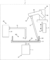
- FIG. 2 is a diagram showing an example of a specific configuration of the cell recovery device 1.
- the cell recovery device 1 is used for recovering the cells contained in the culture container 100.
- the cells to be collected may be single cells or aggregates of a plurality of cells. Further, for example, a cell-containing structure containing an artificially created porous body and cells attached to the surface of the porous body may be a target for collection.
- the cell recovery device 1 is configured to include a rotation drive unit 10, a recovery unit 20, a liquid ejection unit 30, a lift drive unit 40, and a control unit 50.
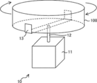
- the rotary drive unit 10 includes a motor 11 and a container holding unit 13.
- the container holder 13 holds the culture container 100 containing cells.
- the rotation shaft 12 of the motor 11 is connected to the container holder 13, and the culture container 100 rotates together with the container holder 13 when the motor 11 is driven.
- the culture container 100 is a container used for cell culture, and has a circular bottom surface 101 and a side wall portion 102 surrounding the outer edge of the bottom surface 101.
- a commercially available culture container having a dish shape can be used as the culture container 100.
- the bottom surface 101 of the culture container 100 is perpendicular to the rotation shaft 12 of the motor 11 and the motor 11 is located at a position corresponding to the center of the bottom surface 101 of the culture container 100.
- the rotary shaft 12 of is located. That is, as shown in FIG. 3, the rotation drive unit 10 rotates the culture container 100 held by the container holding unit 13 around the rotation shaft 12. In the present embodiment, the rotation drive unit 10 rotates the culture container 100 at a low speed of about 60 rpm to 100 rpm, for example.
- the relative centrifugal force (RCF: Relative Centrifugal force) acting on the outer edge of the bottom surface 101 is 0.5.
- RCF Relative Centrifugal force
- the relative centrifugal force acting on the outer edge of the bottom surface 101 becomes 0.18 ⁇ g.
- g is gravity.
- the relative centrifugal force RCF can be calculated by the following equation (1). In the equation (1), r is the radius of rotation [mm], and N is the number of revolutions [rpm].
- the upper limit of the rotation speed of the culture container 100 can be appropriately determined in consideration of damage to cells and protrusion of the cell suspension from the culture container 100 due to centrifugal force.
- the lower limit of the rotation speed of the culture container 100 can be appropriately determined so that cells can be unevenly distributed on the outer edge of the bottom surface 101 of the culture container 100.
- the collection unit 20 includes a nozzle 21 that sucks cells (cell suspension) contained in the culture container 100, and a controller 22 that controls suction of cells (cell suspension) from the nozzle 21. ..
- the recovery unit 20 may include a commercially available electric pipettor.
- the suction port 23 at the tip of the nozzle 21 is arranged at a position corresponding to the outer edge of the bottom surface 101 of the culture container 100.
- the collection unit 20 collects the cells (cell suspension) contained in the culture container 100 by sucking from the suction port 23.
- the elevating and lowering drive unit 40 includes a base unit 41 fixedly installed, a link unit 42 slidably provided with respect to the base unit 41, and a holding plate 43 connected to the link unit 42. There is.
- the controller 22 of the recovery unit 20 is attached to the holding plate 43.
- the recovery part 20 moves up and down as the link part 42 slides in the vertical direction with respect to the base part 41.
- the suction port 23 at the tip of the nozzle 21 is arranged at a position higher than the culture container 100.
- the suction port 23 at the tip of the nozzle 21 is arranged near the bottom surface 101 of the culture container 100 (see FIG. 2).
- the liquid ejecting unit 30 is configured to include a nozzle 31 that ejects a liquid, and a controller 32 that controls the ejection of the liquid from the nozzle 31.
- the discharge port 33 at the tip of the nozzle 31 is arranged at a position corresponding to the rotary shaft 12. That is, the liquid discharger 30 discharges the liquid to the center of rotation of the bottom surface 101 of the culture container 100.
- the liquid ejected from the liquid ejecting section 30 the same kind of medium as the medium contained in the culture container 100 can be used. Further, as the liquid ejected from the liquid ejecting unit 30, it is also possible to use the liquid in which the culture medium in the culture container 100 used for the culture is sucked. As the liquid ejected from the liquid ejecting section 30, it is possible to use a liquid having no cytotoxicity other than the medium.
- the control unit 50 is composed of, for example, an MCU (Micro Controller Unit), and integrally controls the operations of the rotation drive unit 10, the recovery unit 20, the liquid ejection unit 30, and the elevating drive unit 40.
- MCU Micro Controller Unit
- FIG. 4 is a flowchart showing an example of the flow of processing performed by the control unit 50.
- the culture container 100 containing the cells is set in the container holder 13.
- the cells can be cultured in the culture container 100 by an adhesion culture method or a suspension culture method.
- the adherent culture method cells are cultured while being adhered to the bottom surface 101 of the culture container 100.
- pretreatment using an enzyme agent such as trypsin may be appropriately performed. If the adhesive force of the cells to the bottom surface 101 is small, the above pretreatment can be omitted.
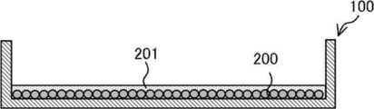
- FIG. 5A is a diagram schematically showing a state of cells in the culture container 100 at the time of being set in the container holding unit 13.
- the cells 200 are uniformly dispersed in the medium 201 in the culture container 100. Since the culture container 100 is held by the container holder 13, the orientation of the bottom surface 101 of the culture container 100 is kept horizontal.
- step S1 the control unit 50 drives the motor 11 by supplying a control signal to the motor 11 of the rotation drive unit 10.
- the culture container 100 held by the container holder 13 rotates. That is, the culture container 100 rotates with the center of the bottom surface 101 as the center of rotation while keeping the orientation of the bottom surface 101 horizontal.
- the rotation speed of the motor 11 is controlled in the range of 60 rpm to 100 rpm, for example.
- a centrifugal force acts on the medium contained in the culture container 100 together with the cells, and a liquid flow is generated from the center portion of the bottom surface 101 of the culture container 100 toward the outer edge portion.
- the centrifugal force also acts on the cells themselves. As a result, the cells contained in the culture container 100 move toward the outer edge of the bottom surface 101 of the culture container 100.
- the centrifugal force acting by the rotation of the culture container 100 is minimized at the center of the bottom surface 101, which is the center of rotation, and almost no liquid flow toward the outer edge of the culture container 100 occurs. Therefore, only by rotating the culture container 100, the cells located in the center of the bottom surface 101 may remain in the center.
- step S2 the control unit 50 supplies a control signal to the liquid ejection unit 30 to eject the liquid from the ejection port 33 at the tip of the nozzle 31 of the liquid ejection unit 30.
- the liquid is ejected onto the center of the bottom surface 101 of the culture container 100.
- the liquid discharger 30 discharges the liquid toward the center of the bottom surface 101 of the culture container 100, thereby promoting the movement of cells located in the center of the bottom surface 101 of the culture container 100 to the outer edge. It is possible to suppress the cells from remaining in the center.
- the liquid ejection may be started before the rotation of the culture container 100 is started.
- the control unit 50 stops the ejection of the liquid from the liquid ejection unit 30 in step S3.
- the rotation of the culture container 100 is continued even after the discharge of the liquid is stopped.
- the cells 200 in the culture container 100 are collected near the outer edge portion of the bottom surface 101 of the culture container 100, that is, the side wall portion 102.
- step S4 the control unit 50 lowers the recovery unit 20 by supplying a control signal to the lift drive unit 40.
- the suction port 23 at the tip of the nozzle 21 of the collection unit 20 is immersed in the medium near the outer edge of the bottom surface 101 of the culture container 100.
- step S5 the control unit 50 operates the recovery unit 20 by supplying a control signal to the controller 22 of the recovery unit 20.
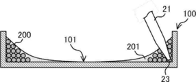
- cells cell suspension
- the suction port 23 of the collection unit 20 is arranged near the outer edge of the bottom surface 101 of the culture container 100 in which the cells 200 are unevenly distributed.
- the collection unit 20 collects the cells 200, which are unevenly distributed on the outer edge of the bottom surface 101 of the culture container 100, into the nozzle 21 by sucking the cells 200.
- the rotation of the culture container 100 is continued while the collection unit 20 is suctioning the cells 200.
- the relative position between the suction port 23 of the nozzle 21 and the culture container 100 is moved by the rotation of the culture container 100. Therefore, it becomes possible to recover, in a short time, almost all of the cells existing around the entire outer edge of the bottom surface 101 of the culture container 100.
- step S6 the control unit 50 determines whether or not a predetermined time has passed since the collection unit 20 started collecting the cells.
- the above-mentioned predetermined time is set to a time sufficient to aspirate almost all of the cells contained in the culture container 100.
- step S6 instead of determining whether or not the predetermined time has elapsed, it may be determined whether or not the suction amount of the cell suspension in the collecting unit 20 has reached the predetermined amount.
- the control unit 50 determines that the predetermined time has elapsed since the collection of the cells by the collection unit 20 was started, the process proceeds to step S7.
- step S7 the control unit 50 stops the operation of the collection unit 20. As a result, suction of cells (cell suspension) in the collection unit 20 is stopped.
- step S8 the control unit 50 raises the recovery unit 20 by supplying a control signal to the lift drive unit 40. As a result, the suction port 23 at the tip of the nozzle 21 of the recovery unit 20 is arranged at a position higher than the culture container 100.
- step S9 the control unit 50 stops driving the motor 11. As a result, the rotation of the culture container 100 is stopped. The cells contained in the culture container 100 are completely recovered through the above processes.
- the culture container 100 accommodating cells rotates around the rotation shaft 12.
- the rotating shaft 12 is arranged at a position orthogonal to the bottom surface 101 of the culture container 100 and corresponding to the center of the bottom surface 101.
- the centrifugal force acts on the cells and the medium contained in the culture container 100, and the cells uniformly dispersed in the culture container 100 can be unevenly distributed on the outer edge portion of the bottom surface 101 of the culture container 100.
- the fact that the rotary shaft 12 is orthogonal to the bottom surface 101 of the culture vessel 100 may be orthogonal within a range that allows an error. Further, the rotating shaft 12 may be inclined with respect to the bottom surface 101 of the culture container 100.
- the rotation speed of the culture container 100 is limited to the range of 60 rpm or more and 100 rpm or less.
- the rotation speed of the culture container 100 by the cell recovery device 1 according to the present embodiment is extremely low.
- the relative centrifugal force acting on the outer edge portion of the bottom surface 101 is 0.5 ⁇ g. In this way, by rotating the culture container 100 at a low speed, the centrifugal force acting on the cells can be reduced, and the aggregation of cells due to the centrifugal force can be suppressed. Therefore, damage to cells can be suppressed.
- the rotation speed of the culture container 100 is low, in the medium contained in the culture container 100, it is possible to generate a liquid flow from the center of the bottom surface 101 of the culture container 100 toward the outer edge. This makes it possible to move the cells toward the outer edge of the bottom surface 101 of the culture container 100.
- the centrifugal force applied by the rotation of the culture container 100 is minimum at the center of the bottom surface 101 of the culture container 100, which is the center of rotation. Therefore, at the center of the bottom surface 101 of the culture container 100, almost no liquid flow toward the outer edge of the culture container 100 occurs. Therefore, the rotation of the culture container 100 alone results in the center of the bottom surface 101 of the culture container 100. The cells may remain in the center.
- the liquid ejection unit 30 ejects the liquid to the central portion of the bottom surface 101 of the culture container 100 before or during the rotation of the culture container 100. This can promote the movement of cells located in the central portion of the bottom surface 101 of the culture container 100 to the outer edge portion, and can suppress the residual cells in the central portion.
- the rotation of the culture container 100 is continued while the cells are recovered by the recovery unit 20.
- the relative position between the suction port 23 of the nozzle 21 of the collection unit 20 and the culture container 100 can be moved. That is, all the cells collected on the outer peripheral portion of the bottom surface 101 of the culture container 100 pass near the suction port 23 of the collection unit 20 due to the rotation of the culture container 100. Therefore, it becomes possible to recover, in a short time, substantially all of the cells existing around the entire outer edge of the bottom surface of the culture container 100.
- the effect of causing the cells to be unevenly distributed on the outer edge portion of the bottom surface 101 of the culture container 100 by the rotation of the culture container 100, and the suction port 23 and the culture container 100 The effect of moving the relative position can be obtained.
- the cell recovery device 1 of the present embodiment it is possible to use a culture container used for culturing cells without using a dedicated container, and it is also possible to use a commercially available culture container. Is. Further, as the culture container 100, for example, one having the following configuration can be used.
- h is the height of the liquid surface of the medium contained in the culture container 100.
- h 0 is the height of the liquid surface of the culture medium before the rotation of the culture container 100 (that is, while the culture container 100 is stationary).
- h max is the height of the side wall portion 102 of the culture container 100.
- h min is the minimum liquid level of the medium required for cell culture.
- RCF max is the maximum magnitude of the relative centrifugal force at which the cell suspension containing the cells and the medium does not come out from the culture container 100.
- RCF min is the minimum magnitude of the relative centrifugal force that allows cells to be unevenly distributed on the outer edge of the bottom surface of the culture container 100.
- the height h of the liquid surface of the culture medium before the rotation of the culture container 100 is h 0 .
- h 0 is determined so as to satisfy h min ⁇ h 0 ⁇ h max .
- FIG. 16B when the culture container 100 rotates, a centrifugal force acts on the medium, and a liquid flow is generated from the center portion of the bottom surface of the culture container 100 toward the outer edge portion. The centrifugal force also acts on the cells themselves. As a result, the cells contained in the culture container 100 move toward the outer edge of the bottom surface 101 of the culture container 100.
- the magnitude of the relative centrifugal force RCF is determined so that the liquid level height h at the outer edge of the culture container 100 at this time satisfies h 0 ⁇ h ⁇ h max . As shown in FIG. 16C, when the magnitude of the relative centrifugal force RCF reaches RCF max , the height h of the liquid surface at the outer edge portion of the culture container 100 becomes h max . When the magnitude of the relative centrifugal force RCF exceeds RCF max and becomes large, the cell suspension containing the medium and the cells jumps out from the culture container 100.
- FIG. 17 is a graph showing the relationship between the liquid level height h 0 before the rotation of the culture container 100 and the relative centrifugal force RCF.
- the solid line is a boundary line indicating whether or not the cell suspension containing the medium and cells jumps out of the culture container 100.
- the height h 0 of the liquid surface before the rotation of the culture container 100 does not become lower than h min and does not become higher than h max .
- Regions 1 and 2 are regions that are not used in the cell recovery method according to this embodiment.
- the regions 3 and 6 in FIG. This is an area that is not used in the cell recovery method.
- the regions 4 and 5 in FIG. 17 are unused regions from the viewpoint of preventing the cell suspension containing cells and the medium from jumping out of the culture container 100. ..
- the relative centrifugal force acting on the outer edge portion of the culture container 100 has a minimum size (RCF min ) that allows cells to be unevenly distributed on the outer edge portion of the bottom surface of the culture container 100.
- the cell suspension containing cells and medium does not jump out of the culture container 100.
- the maximum relative centrifugal force RCF max becomes relatively large.
- the cell suspension containing cells and medium jumps out of the culture container 100.
- the magnitude of the maximum relative centrifugal force RCF max that does not occur becomes relatively small. That is, in this case, the cell suspension is ejected from the culture container 100 with respect to a relatively weak relative centrifugal force.
- the relative centrifugal force exceeds RCF min , the cells can be unevenly distributed in the outer edge portion of the bottom surface of the culture container 100, and the cell recovery method according to the present embodiment is effectively performed. It is possible.
- FIG. 6 is a perspective view showing an example of the overall configuration of the culture container 100A that can be used in the cell recovery device 1.
- the culture container 100A is configured to include a bottom plate 103 formed of a plate-like member, and a side wall portion 102 that surrounds the outer edge of the bottom plate 103 and forms a wall surface in a direction intersecting the main surface of the bottom plate 103.
- the shape of the main surface of the bottom plate 103 is circular, and the outer shape of the culture container 100A is cylindrical. That is, the culture container 100A has the form of a container such as a petri dish (petri dish).
- petri dish petri dish
- the culture container 100A is preferably made entirely of a material that is transparent to visible light so that the state of cells in culture can be observed.
- a thermoplastic resin such as polystyrene can be preferably used as the material of the culture container 100A.
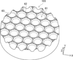
- FIG. 7A and 7B are a partial plan view and a perspective view of the bottom plate 103, showing the structure of the surface of the bottom plate 103 in an enlarged manner, respectively.
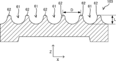
- 8A is a cross-sectional view taken along the line 8-8 in FIG. 7A
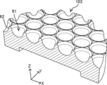
- FIG. 8B is a perspective view of the bottom plate 103 taken along the line 8-8 in FIG. 7A.
- a plurality of recesses 61 for accommodating and culturing cells to be cultured using the culture container 100A are provided on the surface of the bottom plate 103.
- Each of the concave portions 61 has a hemispherical shape.
- the plurality of recesses 61 are arranged on the surface (XY plane) of the bottom plate 103 in a hexagonal close-packed arrangement. That is, each of the plurality of recesses 61 is adjacent to the other six recesses 61.
- Each two recesses 61 adjacent to each other are separated from each other by a partition wall 62 provided between the two recesses 61. That is, the bottom plate 103 has a plurality of partition walls 62 that separate two adjacent recesses 61 from each other.
- the upper surface of the partition wall 62 (the surface on the opening side of the concave portion 61) is a convex non-flat surface.
- the opening diameter D corresponds to the distance between the tops of the partition walls 62
- the distance L corresponds to the depth of the recess 61. 2D ⁇ 3L (2)
- the opening diameter D and the distance L are determined according to the size of a cell mass that is an aggregate of cells cultured using the culture container 100.
- the opening diameter D may be about 1.0 mm, and the distance L may be about 0.5 mm, for example.
- the opening diameter D and the distance L satisfy the expression (1), the cells accommodated and cultured in the recess 61 can move appropriately in the recess 61, and a preferable culture state can be obtained.
- a protrusion 63 having a top higher than the height of the top of the partition wall 62 is provided at each intersection where the plurality of partition walls 62 intersect.
- the shape of the protrusion 63 is not particularly limited.
- the shape of the protrusion 63 is a tetrahedron (triangular pyramid) shape, or It may have a shape in which the apex of the tetrahedron corresponding to the top of the protrusion 63 is cut out.
- the upper surface of the top of the notched protrusion 63 may be flat or curved.
- each of the protrusions 63 is connected to the partition wall 62 between the center (top) of the protrusion 63 and the hem. It will have three inclined surfaces. It is preferable that these three inclined surfaces are respectively inclined toward the three concave portions 61 adjacent to the protrusion 63.
- the shape of the protrusion 63 may be, for example, a conical shape, a truncated cone shape in which the apex of the cone is cut out, a cylindrical shape, or a prismatic shape.
- 9A and 9B are diagrams showing an example of a cell culture method according to an embodiment of the disclosed technology.
- an appropriate amount of medium 201 is poured into the space surrounded by the bottom plate 103 and the side wall portion 102 of the culture container 100A.
- a cell suspension containing cells 200 is injected into the medium 201 poured into the space.
- the cell 200 may include a cell mass that is an aggregate of a single cell and a plurality of single cells.
- the cell 200 may be a cell-containing structure including an artificially created porous body and cells attached to the surface of the porous body.
- the cell suspension is injected so that the cells 200 are substantially uniformly dispersed in the medium 201.
- the type of cells cultured using the cell culture method according to this embodiment is not particularly limited, and may be, for example, animal cells or human cells.
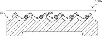
- the cell 200 drops in the medium 201 toward the bottom plate 103 of the culture container 100A by its own weight, is accommodated in the recess 61, and is cultured in the recess 61 as shown in FIG. 9B.
- the cells 200 accommodated in the recess 61 are fused to form a cell mass. Further, the cell 200 accommodated in the recess 61 repeats cell division, so that the size of the cell mass increases. During the culture period, necessary treatments such as a medium exchange treatment are performed every several days, for example, according to a predetermined culture protocol. The culture is terminated when the size of the cell mass formed in the recess 61 has grown to a desired size. Since each recess 61 is separated from the other adjacent recesses 61 by the partition wall 62, the size of the cell mass formed in each recess 61 can be made substantially uniform between the recesses 61.
- Cell clusters that have grown to the desired size are collected and stored.
- the cell collection can be performed using the cell collection device 1. That is, after the culture container 100A is set in the container holding portion 13 of the cell recovery device 1, the cell recovery device 1 is stored in the culture container 100A by performing each process shown in the flowchart of FIG. The cell mass is collected by the cell collection device 1.
- FIG. 10A is a diagram showing a state of cells 200 accommodated in culture container 100A when culture container 100A is in a stationary state.
- the cell 200 remains stationary inside the recess 61.
- centrifugal force acts on the medium.
- a liquid flow toward the outer edge of the culture container 100A is generated in the surface layer of the culture medium, and the surface of the recess 61 of the culture container 100A is formed in the lower layer of the culture medium.
- a liquid flow is generated along. Due to this liquid flow, the cells 200 move along the surface of the recess 61.
- the cell 200 can exit from the recess 61 and can move to the outer edge of the culture container 100A, as shown in FIG. 10C.
- the cells 200 are collected at the outer edge of the culture container 100A and are collected by being sucked from the suction port 23 of the nozzle 21 of the collecting unit 20.
- the cell recovery device 1 As described above, according to the cell recovery device 1 according to the embodiment of the disclosed technique, damage to cells is suppressed while the uneven structure serving as a barrier for cell migration is formed on the bottom surface of the culture container. It is possible to collect cells from the culture vessel.
- FIG. 12 is a diagram showing an example of the configuration of a cell recovery device 1A according to the second embodiment of the disclosed technique.
- the cell collection device 1A includes a discharge/collection unit 70.
- the discharging/collecting unit 70 has both the function of the collecting unit 20 and the function of the liquid discharging unit 30 in the cell collecting apparatus 1 according to the first embodiment.
- the discharge/collection unit 70 includes a syringe 71, a sterile filter 72, a pipe 73, a syringe pushing/pulling unit 74, an elevating unit 75, a swinging unit 76, and a nozzle 77.
- the syringe 71 is held by a syringe pushing/pulling unit 74.
- the plunger of the syringe 71 moves in the pushing direction, and the gas contained in the syringe 71 pressurizes the inside of the nozzle 77 via the sterile filter 72 and the pipe 73.
- the liquid contained in the nozzle 77 is discharged from the discharge/suction port 78.
- the plunger of the syringe 71 moves in the pulling direction, and the liquid sucked from the discharge/suction port 78 of the nozzle 77 is stored in the nozzle 77.
- the oscillating unit 76 rotates around a rotation axis arranged near the connection between the nozzle 77 and the pipe 73, thereby moving the tip of the nozzle 77 in the radial direction of the culture container 100.
- the lifting unit 75 moves the nozzle 77 up and down.
- FIG. 13 is a flowchart showing an example of the flow of processing performed by the control unit 50.
- step S11 the control unit 50 drives the swing unit 76 to move the tip of the nozzle 77 to the center of the bottom surface 101 of the culture container 100.
- step S12 the control unit 50 lowers the syringe push/pull unit 74.
- the plunger of the syringe 71 moves in the direction in which it is pulled out, the cell suspension in the culture container 100 is sucked from the discharge/suction port 78 of the nozzle 77, and is stored in the nozzle 77.
- step S13 the control unit 50 drives the motor 11.
- the culture container 100 held by the container holder 13 rotates, and the cells contained in the culture container 100 move toward the outer edge of the bottom surface 101 of the culture container 100.
- step S14 the control unit 50 raises the syringe pushing/pulling unit 74.
- the plunger of the syringe 71 moves in the pushing direction, and the cell suspension contained in the nozzle 77 is discharged from the discharge/suction port 78 of the nozzle 77.
- the cells located in the central portion of the bottom surface 101 of the culture vessel 100 can be promoted to move to the outer edge portion, and the residual of the cells in the central portion is suppressed.
- step S15 the control unit 50 stops the syringe pushing/pulling unit 74. As a result, the discharge of the cell suspension from the discharge/suction port 78 is stopped.
- step S16 the control unit 50 drives the swinging unit 76 to move the tip of the nozzle 77 to the outer edge of the bottom surface 101 of the culture container 100.
- step S17 the control unit 50 lowers the syringe push/pull unit 74.
- the plunger of the syringe 71 moves in the direction of withdrawing, and the cell suspension containing cells unevenly distributed on the outer edge of the bottom surface 101 of the culture container 100 is sucked from the discharge/suction port 78 of the nozzle 77, It is housed in 77.
- the rotation of the culture container 100 is continued while the discharge/collection unit 70 sucks the cell suspension. Therefore, the relative position between the discharge/suction port 78 of the nozzle 77 and the culture container 100 is moved by the rotation of the culture container 100. Therefore, it becomes possible to recover, in a short time, almost all of the cells existing around the entire outer edge of the bottom surface 101 of the culture container 100.
- step S18 the control unit 50 determines whether or not the suction of the designated amount of cell suspension has been completed.
- the control unit 50 stops the syringe pushing/pulling unit 74 in step S19. As a result, suction of the cell suspension from the discharge/suction port 78 is stopped.
- step S20 the control unit 50 raises the elevating unit 75. As a result, the nozzle 21 rises, and the discharge/suction port 78 of the nozzle 21 is arranged at a position higher than the culture container 100.
- step S21 the control unit 50 stops driving the motor 11. As a result, the rotation of the culture container 100 is stopped.
- the discharge/collection unit 70 has both the function of the collection unit 20 and the function of the liquid discharge unit 30 in the cell collection device 1 according to the first embodiment, and therefore the configuration of the cell collection device 1A. Can be simplified.
- Example 10 the result of collecting the cell-containing structure in which the artificially created porous body and cells are combined using the cell recovery device 1 will be described.
- the culture container 100 is tilted, and the culture container 100 is tilted.
- the culture container 100 is tilted.
- the culture container 100 is tilted.
- the results of collecting the cell structures at the bottom of the cell and collecting them by suction will be described.
- a culture container having a structure having a plurality of recesses on the bottom surface as shown in FIGS. 6 to 8 was used as the culture container.
- the bottom of the culture vessel was circular with a diameter of 90 mm.
- the rotation speed of the culture container was adjusted to a range of 60 rpm to 100 rpm.
- FIG. 14 is a histogram showing the size distribution of the cell-containing structures collected by the method according to the example and the comparative example.
- the size distribution of the cell-containing structure before recovery was substantially the same in the example and the comparative example.
- Cell3i Magerneo CC-3000 manufactured by SCREEN Holdings was used to measure the size of the cell-containing structure.
- the content rate of the cell-containing structure having a relatively small size (220 ⁇ m or less) was higher than that when the cell recovery method according to the example was applied.
- FIG. 15 is a graph showing the results of comparing the amounts of ATP (adenosine triphosphate: adenosine triphosphate) produced in the cell-containing structures collected by the methods according to Examples and Comparative Examples.
- Cytation 5 (Cytation is a registered trademark) CYT5MPV manufactured by BioTek was used for measuring the ATP production amount.
- the ATP production amount in the cell-containing structure according to the comparative example is 100%.
- the cell-containing structure according to the example produced a larger amount of ATP. That is, it is considered that the cell recovery method according to the example causes less damage to the cells than the cell recovery method according to the comparative example.
Landscapes
- Health & Medical Sciences (AREA)
- Life Sciences & Earth Sciences (AREA)
- Engineering & Computer Science (AREA)
- Chemical & Material Sciences (AREA)
- Bioinformatics & Cheminformatics (AREA)
- Wood Science & Technology (AREA)
- Zoology (AREA)
- Organic Chemistry (AREA)
- Biotechnology (AREA)
- Biomedical Technology (AREA)
- Genetics & Genomics (AREA)
- Biochemistry (AREA)
- General Engineering & Computer Science (AREA)
- General Health & Medical Sciences (AREA)
- Microbiology (AREA)
- Medicinal Chemistry (AREA)
- Sustainable Development (AREA)
- Cell Biology (AREA)
- Apparatus Associated With Microorganisms And Enzymes (AREA)
- Micro-Organisms Or Cultivation Processes Thereof (AREA)
Abstract
細胞が収容された培養容器を、培養容器の底面と交差する回転軸の周りに回転させ、培養容器の回転前または回転中に、培養容器の底面の回転中心に液体を噴射し、培養容器の底面の外縁部に前記細胞を偏在させ、前記培養容器の底面の外縁部に偏在する前記細胞を回収する。
Description
開示の技術は、細胞回収方法及び細胞回収装置に関する。
容器内に収容された細胞を回収する技術として、以下のものが知られている。例えば、特開2010-148451号公報には、円筒面状の側壁と、側壁に周方向に間隔をあけて半径方向外方に窪む複数の凹部とを備え、細胞懸濁液を収容して、側壁の中心軸回りに回転させられる容器本体と、容器本体の各凹部の底面近傍に吐出口を配置する洗浄液供給管と、隣接する凹部の間の側壁に対向して吸引口を配置する吸引管とを備える。
細胞培養において、細胞の品質を均一にするため、細胞は、培養容器の底面に均一に分散されていることが好ましい。一方、培養容器内で培養された細胞を、培養容器から回収する際には、細胞へのダメージを抑制し、細胞の回収率を高める観点から、細胞を短時間で回収することが好ましい。細胞を効率的に回収するためには、培養容器の底面に均一に分散された細胞を、培養容器内の特定の箇所に偏在させることが好ましい。
細胞を偏在させる一般的な手段として、遠心機による遠心分離が挙げられる。しかしながら、遠心機による遠心分離には、遠沈管と呼ばれる専用容器が必要となり、細胞の培養に用いられる培養容器を使用することは困難である。また、遠心機による遠心分離においては、一般的に数百Gの遠心力が数分間に亘り作用することから、細胞にダメージを与えるおそれがある。また、過大な遠心力により、細胞の凝集体が形成され、凝集体の中心部の細胞への酸素供給が不十分となり、細胞死に至るおそれがある。
開示の技術は、細胞へのダメージを抑制しつつ、培養容器から細胞を回収することを目的とする。
開示の技術に係る細胞回収方法は、細胞が収容された培養容器を、培養容器の底面と交差する回転軸の周りに回転させ、培養容器の回転前または回転中に、培養容器の底面の回転中心に液体を吐出し、培養容器の底面の外縁部に細胞を偏在させ、培養容器の底面の外縁部に偏在する細胞を回収することを含む。
開示の技術に係る細胞回収方法によれば、細胞へのダメージを抑制しつつ、培養容器から細胞を回収することが可能となる。
培養容器の底面の外縁部において作用する相対遠心力は、培養容器の底面の外縁部に細胞を偏在させることが可能な最小限の大きさより大きく、且つ細胞の培養容器からの飛び出しが生じない最大限の大きさよりも小さいことが好ましい。これにより、細胞の培養容器からの飛び出しを抑制しつつ、培養容器の底面の外縁部に細胞を偏在させることが可能となる。
開示の技術に係る細胞回収方法においては、培養容器を回転軸の周りに回転させながら、培養容器の底面の外縁部に対応する位置に配置された吸引口から細胞を吸引することにより細胞を回収してもよい。これにより、吸引口と培養容器との相対位置の移動を、培養容器の回転によって行うことが可能となる。
培養容器が回転する回転軸が、培養容器の底面の中心部に対応する位置に配置されていてもよい。これにより、培養容器の底面の外縁部への移動が促進される。
培養容器の底面には、細胞を収容するための複数の凹部が設けられていてもよい。これにより、凹部内に形成される細胞塊のサイズを、凹部間で略均一にすることができる。
開示の技術に係る細胞回収装置は、培養容器を、培養容器の底面と交差する回転軸の周りに回転させるための回転駆動部と、培養容器の底面の外縁部に対応する位置に配置された吸引口から培養容器に収容された細胞を吸引することにより回収する回収部と、培養容器の底面の回転中心に液体を吐出する液体吐出部と、を含む。
開示の技術に係る細胞回収装置によれば、細胞へのダメージを抑制しつつ、培養容器から細胞を回収することが可能となる。
培養容器の底面の外縁部において作用する相対遠心力は、培養容器の底面の外縁部に細胞を偏在させることが可能な最小限の大きさより大きく、且つ細胞の培養容器からの飛び出しが生じない最大限の大きさよりも小さいことが好ましい。これにより、細胞の培養容器からの飛び出しを抑制しつつ、培養容器の底面の外縁部に細胞を偏在させることが可能となる。
回転駆動部は、回収部において細胞を回収している間、培養容器を前記回転軸の周りに回転させてもよい。これにより、吸引口と培養容器との相対位置の移動を、培養容器の回転によって行うことが可能となる。
培養容器が回転する回転軸が、前記培養容器の底面の中心部に対応する位置に配置されていてもよい。これにより、培養容器の底面の外縁部への移動が促進される。
開示の技術によれば、細胞へのダメージを抑制しつつ、培養容器から細胞を回収することが可能となる。
以下、本発明の実施形態について図面を参照しつつ説明する。尚、各図面において、実質的に同一又は等価な構成要素又は部分には同一の参照符号を付している。
[第1の実施形態]
図1は、開示の技術の第1の実施形態に係る細胞回収装置1の機能的な構成の一例を示す機能ブロック図である。図2は、細胞回収装置1の具体的な構成の一例を示す図である。細胞回収装置1は、培養容器100内に収容された細胞を回収する用途で使用される。回収の対象となる細胞は、単一細胞であってもよいし、複数の細胞が凝集した凝集体であってもよい。また、例えば、人工的に作成された多孔質体と、この多孔質体の表面に付着させた細胞とを含む細胞含有構造物を回収の対象としてもよい。細胞回収装置1は、回転駆動部10、回収部20、液体吐出部30、昇降駆動部40及び制御部50を含んで構成されている。
図1は、開示の技術の第1の実施形態に係る細胞回収装置1の機能的な構成の一例を示す機能ブロック図である。図2は、細胞回収装置1の具体的な構成の一例を示す図である。細胞回収装置1は、培養容器100内に収容された細胞を回収する用途で使用される。回収の対象となる細胞は、単一細胞であってもよいし、複数の細胞が凝集した凝集体であってもよい。また、例えば、人工的に作成された多孔質体と、この多孔質体の表面に付着させた細胞とを含む細胞含有構造物を回収の対象としてもよい。細胞回収装置1は、回転駆動部10、回収部20、液体吐出部30、昇降駆動部40及び制御部50を含んで構成されている。
回転駆動部10は、モータ11及び容器保持部13を含んで構成されている。容器保持部13は、細胞が収容された培養容器100を保持する。モータ11の回転軸12は、容器保持部13に接続されており、モータ11が駆動されることで、培養容器100は、容器保持部13とともに回転する。
培養容器100は、細胞培養に用いられる容器であり、円形の底面101と、底面101の外縁部を囲む側壁部102とを有する。培養容器100として、例えばディッシュ状の形態を有する市販の培養容器を用いることが可能である。
培養容器100が容器保持部13に保持された状態において、培養容器100の底面101がモータ11の回転軸12に対して垂直となり且つ培養容器100の底面101の中心部に対応する位置にモータ11の回転軸12が位置する。すなわち、回転駆動部10は、図3に示すように、容器保持部13に保持された培養容器100を、回転軸12の周りに回転させる。本実施形態において、回転駆動部10は、例えば60rpm~100rpm程度の低速回転で培養容器100を回転させる。例えば、培養容器100の底面101の半径が例えば45mmである場合、培養容器100が100rpmで回転するとき、底面101の外縁部において作用する相対遠心力(RCF:Relative Centrifugal force)は、0.5×gとなり、培養容器100が60rpmで回転するとき、底面101の外縁部において作用する相対遠心力は0.18×gとなる。ここで、gは重力である。なお、相対遠心力RCFは、下記の(1)式によって求めることができる。(1)式においてrは回転半径[mm]であり、Nは、回転数[rpm]である。
RCF=1118×r×N2×10-9 ・・・(1)
なお、培養容器100の回転速度の上限は、細胞へのダメージ及び遠心力による培養容器100からの細胞懸濁液の飛び出し等を考慮して適宜定めることが可能である。また、培養容器100の回転速度の下限は、培養容器100の底面101の外縁部に細胞を偏在させることができるように適宜定めることが可能である。
RCF=1118×r×N2×10-9 ・・・(1)
なお、培養容器100の回転速度の上限は、細胞へのダメージ及び遠心力による培養容器100からの細胞懸濁液の飛び出し等を考慮して適宜定めることが可能である。また、培養容器100の回転速度の下限は、培養容器100の底面101の外縁部に細胞を偏在させることができるように適宜定めることが可能である。
回収部20は、培養容器100に収容された細胞(細胞懸濁液)を吸引するノズル21と、ノズル21からの細胞(細胞懸濁液)の吸引を制御するコントローラ22と、を備えている。回収部20は、市販の電動ピペッタを含んで構成されてもよい。ノズル21の先端部の吸引口23は、培養容器100の底面101の外縁部に対応する位置に配置されている。回収部20は、培養容器100に収容された細胞(細胞懸濁液)を、吸引口23から吸引することにより回収する。
昇降駆動部40は、固定設置されたベース部41と、ベース部41に対して摺動可能に設けられたリンク部42と、リンク部42に接続された保持板43とを含んで構成されている。保持板43には、回収部20のコントローラ22が取り付けられている。リンク部42が、ベース部41に対して上下方向に摺動することで、回収部20が昇降する。回収部20が、最も高い位置にある場合、ノズル21の先端部の吸引口23が、培養容器100よりも高い位置に配置される。一方、回収部20が、最も低い位置にある場合、ノズル21の先端部の吸引口23が、培養容器100の底面101の近傍に配置される(図2参照)。
液体吐出部30は、液体を吐出するノズル31と、ノズル31からの液体の吐出を制御するコントローラ32と、を含んで構成されている。ノズル31の先端部の吐出口33は、回転軸12に対応する位置に配置されている。すなわち、液体吐出部30は、培養容器100の底面101の回転中心に液体を吐出する。液体吐出部30から吐出される液体として、培養容器100に収容される培地と同じ種類の培地を用いることができる。また、液体吐出部30から吐出される液体として、培養に使用した培養容器100内の培地を吸引したものを利用することも可能である。なお、液体吐出部30から吐出される液体として細胞毒性を有さない、培地以外の液体を用いることも可能である。
制御部50は、例えば、MCU(Micro Controller Unit)により構成され、回転駆動部10、回収部20、液体吐出部30及び昇降駆動部40の動作を統括的に制御する。
以下に、細胞回収装置1の動作について説明する。図4は、制御部50が実施する処理の流れの一例を示すフローチャートである。
はじめに、細胞を収容した培養容器100が、容器保持部13にセットされる。細胞は、培養容器100内において、接着培養方式または浮遊培養方式により培養され得る。接着培養方式においては、細胞は培養容器100の底面101に接着した状態で培養される。この場合、細胞を培養容器100の底面101から剥離するために、トリプシン等の酵素剤を用いた前処理を適宜行ってもよい。なお、細胞の底面101に対する接着力が小さい場合には、上記の前処理を省略することが可能である。
ここで、図5Aは、容器保持部13にセットされた時点における培養容器100内の細胞の状態を模式的に示す図である。接着培養方式及び浮遊培養方式のいずれの方式においても、図5Aに示すように、細胞200は、培養容器100内において培地201中に均一に分散される。培養容器100が容器保持部13に保持されることで、培養容器100の底面101の向きは水平に保たれる。
ステップS1において、制御部50は、回転駆動部10のモータ11に制御信号を供給することでモータ11を駆動させる。これにより、容器保持部13に保持された培養容器100が回転する。すなわち、培養容器100は、底面101の向きを水平に保ったまま、底面101の中心部を回転中心として回転する。モータ11の回転速度は、例えば、60rpm~100rpmの範囲に制御される。培養容器100が回転することで、培養容器100に細胞とともに収容された培地に遠心力が作用し、培養容器100の底面101の中心部から外縁部に向けた液流が発生する。また、遠心力は細胞自体にも作用する。これにより、培養容器100に収容された細胞は、培養容器100の底面101の外縁部に向けて移動する。
培養容器100が回転することにより作用する遠心力は、回転中心となる底面101の中心部において最小となり、培養容器100の外縁部に向かう液流が殆ど生じない。従って、培養容器100の回転のみでは、底面101の中心部に位置する細胞は、中心部に残留するおそれがある。
そこで、ステップS2において、制御部50は、液体吐出部30に制御信号を供給することで液体吐出部30のノズル31の先端部の吐出口33から液体を吐出させる。これにより、図5Bに示すように、培養容器100の底面101の中心部に液体が噴射される。液体吐出部30が、培養容器100の底面101の中心部に向けて液体を吐出することで、培養容器100の底面101の中心部に位置する細胞の、外縁部への移動を促進させることができ、中心部における細胞の残留が抑制される。なお、培養容器100の回転を開始する前に液体の吐出を開始してもよい。
液体吐出部30から所定量の液体が吐出された後、ステップS3において、制御部50は、液体吐出部30からの液体の吐出を停止させる。液体の吐出の停止後においても、培養容器100の回転が継続される。これにより、図5Cに示すように、培養容器100内の細胞200は、培養容器100の底面101の外縁部、すなわち、側壁部102の近傍に集められる。
ステップS4において、制御部50は、昇降駆動部40に制御信号を供給することで回収部20を降下させる。これにより、図5Dに示すように、回収部20のノズル21の先端部の吸引口23が、培養容器100の底面101の外縁部の近傍において培地中に浸漬された状態となる。
ステップS5において、制御部50は、回収部20のコントローラ22に制御信号を供給することで回収部20を稼働させる。これにより、回収部20の吸引口23から細胞(細胞懸濁液)が吸引される。図5Dに示すように、回収部20の吸引口23は、細胞200が偏在している培養容器100の底面101の外縁部の近傍に配置される。回収部20は、培養容器100の底面101の外縁部に偏在している細胞200を吸引することによりノズル21内に回収する。回収部20が細胞200の吸引を行っている間、培養容器100の回転が継続される。従って、ノズル21の吸引口23と培養容器100との相対位置の移動が、培養容器100の回転によって行われる。従って、培養容器100の底面101の外縁部の全周に亘って存在する細胞の略全てを、短時間で回収することが可能となる。
ステップS6において、制御部50は、回収部20による細胞の回収を開始してから所定時間が経過したか否かを判定する。上記の所定時間としては、培養容器100に収容された細胞の略全てを吸引するのに十分な時間が設定される。なお、ステップS6において、所定時間が経過したか否かを判定することに代えて、回収部20における細胞懸濁液の吸引量が所定量に達したか否かを判定してもよい。制御部50は、回収部20による細胞の回収を開始してから所定時間が経過したと判定すると、処理をステップS7に移行する。
ステップS7において、制御部50は、回収部20の稼働を停止させる。これにより、回収部20における細胞(細胞懸濁液)の吸引が停止する。ステップS8において、制御部50は、昇降駆動部40に制御信号を供給することで回収部20を上昇させる。これにより、回収部20のノズル21の先端部の吸引口23が、培養容器100よりも高い位置に配置される。ステップS9において、制御部50は、モータ11の駆動を停止させる。これにより、培養容器100の回転が停止する。以上の各処理を経ることにより、培養容器100に収容された細胞の回収が完了する。
以上の説明から明らかなように、開示の技術の実施形態に係る細胞回収装置1によれば、細胞が収容された培養容器100が、回転軸12の周りに回転する。回転軸12は、培養容器100の底面101と直交し且つ底面101の中心部に対応する位置に配置されている。これにより、培養容器100内に収容された細胞及び培地に遠心力が作用し、培養容器100内に均一に分散された細胞を、培養容器100の底面101の外縁部に偏在させることができる。なお、回転軸12が、培養容器100の底面101と直交しているとは、誤差を許容する範囲内において直交していればよい。また、回転軸12は、培養容器100の底面101に対して傾斜していてもよい。
本実施形態において、培養容器100の回転速度は、60rpm以上100rpm以下の範囲に制限される。ここで、遠心機を用いた遠心分離における一般的な回転速度が、数千rpmであることを考慮すると、本実施形態に係る細胞回収装置1による培養容器100の回転速度は、極めて低速であるといえる。なお、例えば、培養容器100の底面101の半径が例えば45mmである場合、培養容器100が100rpmで回転するとき、底面101の外縁部において作用する相対遠心力は、0.5×gである。このように、培養容器100を低速で回転させることで、細胞に作用する遠心力を小さくすることができ、遠心力による細胞の凝集を抑制することができる。従って、細胞へのダメージを抑制することができる。
一方、培養容器100の回転速度が低速であっても、培養容器100内に収容された培地において、培養容器100の底面101の中心部から外縁部に向かう液流を生じさせることができる。これにより、培養容器100の底面101の外縁部に向けて細胞を移動させることが可能となる。培養容器100が回転することにより作用する遠心力は、回転中心となる培養容器100の底面101の中心部において最小となる。従って、培養容器100の底面101の中心部において、培養容器100の外縁部に向かう液流が殆ど生じないことから、培養容器100の回転のみでは、培養容器100の底面101の中心部に位置する細胞は、中心部に残留するおそれがある。本実施形態に係る細胞回収装置1によれば、培養容器100の回転前または回転中に、液体吐出部30が、培養容器100の底面101の中心部に液体を吐出する。これにより、培養容器100の底面101の中心部に位置する細胞の、外縁部への移動を促進させることができ、中心部における細胞の残留を抑制することができる。
また、本実施形態に係る細胞回収装置1によれば、回収部20において細胞を回収している間、培養容器100の回転が継続される。これにより、回収部20のノズル21の吸引口23と培養容器100との相対位置を移動させることができる。すなわち、培養容器100の底面101の外周部に集められた全ての細胞は、培養容器100の回転により、回収部20の吸引口23の近傍を通過する。従って、培養容器100の底面の外縁部の全周に亘って存在する細胞の略全てを、短時間で回収することが可能となる。このように、本実施形態に係る細胞回収装置1によれば、培養容器100の回転により、培養容器100の底面101の外縁部に細胞を偏在させる効果と、吸引口23と培養容器100との相対位置を移動させる効果とを得ることができる。
また、本実施形態に係る細胞回収装置1によれば、専用の容器を必要とせず、細胞の培養に使用した培養容器を使用することが可能であり、市販の培養容器を使用することも可能である。また、培養容器100として、例えば、以下の構成を有するものを使用することが可能である。
ここで、培養容器100の回転に伴って作用する相対遠心力RCFの好ましい範囲について、図16A~図16C及び図17を参照しつつ説明する。なお、図16A~16C及び図17において、hは培養容器100に収容された培地の液面の高さである。h0は、培養容器100の回転前(すなわち静止中)における培地の液面の高さである。hmaxは、培養容器100の側壁部102の高さである。hminは、細胞培養に必要な最小限の培地の液面の高さである。RCFmaxは、培養容器100から、細胞及び培地を含む細胞懸濁液が飛び出さない相対遠心力の最大限の大きさである。RCFminは、培養容器100の底面の外縁部に細胞を偏在させることが可能な相対遠心力の最小限の大きさである。
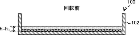
図16Aに示すように、培養容器100の回転前(静止中)における培地の液面の高さhはh0である。このとき、hmin<h0<hmaxを満たすように、h0が定められる。図16Bに示すように、培養容器100が回転すると、培地に遠心力が作用し、培養容器100の底面の中心部から外縁部に向けた液流が発生する。また、遠心力は細胞自体にも作用する。これにより、培養容器100に収容された細胞は、培養容器100の底面101の外縁部に向けて移動する。このときの培養容器100の外縁部における液面の高さhについて、h0<h<hmaxを満たすように、相対遠心力RCFの大きさが定められる。図16C示すように、相対遠心力RCFの大きさがRCFmaxに達すると、培養容器100の外縁部における液面の高さhは、hmaxとなる。相対遠心力RCFの大きさがRCFmaxを超えて大きくなると、培地及び細胞を含む細胞懸濁液が培養容器100から飛び出してしまうことになる。
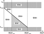
図17は、培養容器100の回転前における液面の高さh0と、相対遠心力RCFとの関係を示したグラフである。図17に示すグラフにおいて、実線は、培地及び細胞を含む細胞懸濁液が培養容器100から飛び出すか、飛び出さないかの境界線である。
本実施形態に係る細胞回収方法において、培養容器100の回転前における液面の高さh0がhminよりも低くなることはなく、またhmaxよりも高くなることはないので、図17における領域1及び領域2は、本実施形態に係る細胞回収方法において使用しない領域である。また、本実施形態に係る細胞回収方法においては、培養容器100の底面の外縁部への細胞の偏在を可能とする必要があることから、図17における領域3及び領域6は、本実施形態に係る細胞回収方法において使用しない領域である。また、本実施形態に係る細胞回収方法においては、細胞及び培地を含む細胞懸濁液の培養容器100からの飛び出しを回避する観点から、図17における領域4及び領域5は、使用しない領域である。本実施形態に係る細胞回収方法においては、培養容器100の外縁部において作用する相対遠心力が、培養容器100の底面の外縁部に細胞を偏在させることが可能な最小限の大きさ(RCFmin)より大きく、且つ細胞懸濁液の培養容器100からの飛び出しが生じない最大限の大きさ(RCFmax)よりも小さい領域7が使用される。
培養容器100の回転前における液面の高さh0が相対的に低い場合(すなわち、液量が相対的に少ない場合)、細胞及び培地を含む細胞懸濁液が培養容器100から飛び出さない最大限の相対遠心力RCFmaxの大きさが相対的に大きくなる。一方、培養容器100の回転前における液面の高さh0が相対的に高い場合(すなわち、液量が相対的に多い場合)、細胞及び培地を含む細胞懸濁液が培養容器100から飛び出さない最大限の相対遠心力RCFmaxの大きさが相対的に小さくなる。すなわち、この場合、相対的に弱い相対遠心力に対して、細胞懸濁液の培養容器100からの飛び出しが発生する。しかしながら、この場合でも、相対遠心力がRCFminを超えていれば、培養容器100の底面の外縁部に細胞を偏在させることが可能であり、本実施形態に係る細胞回収方法を有効に実施することが可能である。
図6は、細胞回収装置1に用いることができる、培養容器100Aの全体の構成の一例を示す斜視図である。培養容器100Aは、板状部材からなる底板103と、底板103の外縁を囲み、底板103の主面と交差する方向に壁面を形成する側壁部102とを含んで構成されている。底板103の主面の形状は円形とされており、培養容器100Aの外形は円柱状である。すなわち、培養容器100Aはシャーレ(ペトリ皿)等の容器の形態を有している。
培養容器100Aは、培養中の細胞の状態を観察できるように、全体が可視光に対して透過性を有する材料で構成されていることが好ましい。培養容器100Aを例えば、射出成形によって製造する場合、培養容器100Aの材料として、ポリスチレン等の熱可塑性樹脂を好適に用いることができる。
図7A及び図7Bは、それぞれ、底板103の表面の構造を拡大して示す、底板103の部分的な平面図及び斜視図である。図8Aは、図7Aにおける8-8線に沿った断面図であり、図8Bは、図7Aにおける8-8線に沿って切断した底板103の斜視図である。
底板103の表面には、培養容器100Aを用いて培養される細胞を収容し、培養するための複数の凹部61が設けられている。凹部61の各々の形状は半球状とされている。図7A及び図7Bに示すように、複数の凹部61は、底板103の表面(X-Y平面)に六方最密配列の形態で配列されている。すなわち、複数の凹部61の各々は、6つの他の凹部61に隣接している。互いに隣接する各2つの凹部61は、当該2つの凹部61の間に設けられた隔壁62によって互いに隔てられている。すなわち、底板103は、互いに隣接する各2つの凹部61を互いに隔てる複数の隔壁62を有する。
図8A及び図8Bに示すように、本実施形態において、隔壁62の上面(凹部61の開口側の面)が、凸状の非平坦面となっている。ここで、凹部61の底部と隔壁62の頂部との間の、高さ方向(Z方向)における距離をLとし、凹部61の開口径をDとしたとき、下記の(2)式を満たすことが好ましい。なお、開口径Dは、隔壁62の頂部間の距離に相当し、距離Lは、凹部61の深さに相当する。
2D≧3L ・・・(2)
2D≧3L ・・・(2)
開口径D及び距離Lは、培養容器100を用いて培養される細胞の凝集体である細胞塊のサイズに応じて定められる。開口径Dは、一例として、1.0mm程度であってもよく、距離Lは、例えば0.5mm程度であってもよい。開口径Dと距離Lとが(1)式を満たすことで、凹部61内に収容され、培養される細胞が、凹部61内で適度に動くことができ、好ましい培養状態を得ることができる。
図7A、図7Bに示すように、底板103の表面には、複数の隔壁62が交差する各交差部に、隔壁62の頂部の高さよりも高い頂部を有する突起部63が設けられている。突起部63の形状は特に限定されないが、例えば、複数の凹部61が、六方最密配列の形態で配列されている場合には、突起部63の形状は、四面体(三角錐)状または、突起部63の頂部に対応する四面体の頂点を切り欠いた形状であってもよい。この場合、切り欠かれた突起部63の頂部の上面は、平坦であってもよく、湾曲していてもよい。
突起部63の形状を四面体状または四面体の頂点を切り欠いた形状とした場合、突起部63の各々は、突起部63の中央部(頂部)から裾部の間で、隔壁62に連なる傾斜した3つの傾斜面を有することになる。これら3つの傾斜面は、それぞれ、当該突起部63に隣接する3つの凹部61に向けて傾斜していることが好ましい。なお、突起部63の形状は、例えば円錐形状、円錐の頂点を切り欠いた円錐台形状、円柱形状または角柱形状であってもよい。
以下に、培養容器100Aを用いた細胞培養方法の一例について説明する。図9A及び図9Bは、開示の技術の実施形態に係る細胞培養方法の一例を示す図である。
初めに、培養容器100Aの底板103及び側壁部102によって囲まれた空間内に適量の培地201を注ぐ。続いて、図9Aに示すように、上記の空間内に注がれた培地201中に、細胞200を含む細胞懸濁液を注入する。細胞200は、単一細胞及び複数の単一細胞の凝集体である細胞塊を含み得る。また、細胞200は、人工的に作成された多孔質体と、この多孔質体の表面に付着した細胞とを含む細胞含有構造物であってもよい。細胞懸濁液は、細胞200が培地201中で略均一に分散するように注入される。なお、本実施形態に係る細胞培養方法を用いて培養される細胞の種類は、特に限定されるものではなく、例えば動物細胞及びヒト細胞であってもよい。細胞200は、自重によって培養容器100Aの底板103に向けて培地201中を落下して、図9Bに示すように、凹部61内に収容され、凹部61内で培養される。
凹部61内に収容された細胞200同士が融合することで細胞塊が形成される。また、凹部61内に収容された細胞200が、細胞分裂を繰り返すことで、細胞塊のサイズが大きくなる。培養期間中、所定の培養プロトコルに従って、例えば数日おきに培地交換処理等の必要な処理が施される。凹部61内に形成された細胞塊のサイズが、所望のサイズにまで成長した段階で培養を終了させる。各凹部61は、隔壁62によって、隣接する他の凹部61と分離されているので、各凹部61内に形成される細胞塊のサイズを、凹部61間で略均一にすることができる。
所望のサイズにまで成長した細胞塊は、回収され、保存される。細胞塊の回収は、細胞回収装置1を用いて行うことが可能である。すなわち、培養容器100Aが、細胞回収装置1の容器保持部13にセットされた後、細胞回収装置1が、図4のフローチャートに示される各処理を実施することで、培養容器100Aに収容された細胞塊が、細胞回収装置1に回収される。
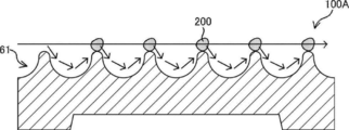
図10Aは、培養容器100Aが静止状態にある場合の、培養容器100Aに収容された細胞200の様子を示す図である。この場合、細胞200は、凹部61内において静止状態を維持する。モータ11が駆動され、培養容器100が回転を開始すると、培地に遠心力が作用する。これにより、図10Bにおいて、矢印によって示されるように、培地の表層部においては、培養容器100Aの外縁部に向かう液流が発生し、培地の下層部においては、培養容器100Aの凹部61の表面に沿った液流が発生する。この液流により、細胞200は、凹部61の表面に沿って移動する。細胞200は、細胞200に作用する微小な遠心力及び液流により、図10Cに示すように、凹部61から出ることが可能となり、培養容器100Aの外縁部へ移動することが可能である。培養容器100Aの回転を継続させることで、細胞200が培養容器100Aの外縁部に集められ、回収部20のノズル21の吸引口23から吸引されることにより回収される。
このように、開示の技術の実施形態に係る細胞回収装置1によれば、培養容器の底面に細胞の移動の障壁となる凹凸構造が形成されている場合でも、細胞へのダメージを抑制しつつ培養容器から細胞を回収することが可能である。
[第2の実施形態]
図12は、開示の技術の第2の実施形態に係る細胞回収装置1Aの構成の一例を示す図である。細胞回収装置1Aは、吐出・回収部70を備えている。吐出・回収部70は、第1の実施形態に係る細胞回収装置1における回収部20の機能と、液体吐出部30の機能とを兼ね備えている。
図12は、開示の技術の第2の実施形態に係る細胞回収装置1Aの構成の一例を示す図である。細胞回収装置1Aは、吐出・回収部70を備えている。吐出・回収部70は、第1の実施形態に係る細胞回収装置1における回収部20の機能と、液体吐出部30の機能とを兼ね備えている。
吐出・回収部70は、シリンジ71、無菌フィルタ72、配管73、シリンジ押し引きユニット74、昇降ユニット75、首振りユニット76及びノズル77を含んで構成されている。シリンジ71は、シリンジ押し引きユニット74に保持されている。シリンジ押し引きユニット74が上昇することで、シリンジ71のプランジャが押し込まれる方向に移動し、シリンジ71内に収容された気体が、無菌フィルタ72、配管73を介して、ノズル77内を加圧することでノズル77に収容された液体を吐出・吸引口78から吐出する。一方、シリンジ押し引きユニット74が降下することで、シリンジ71のプランジャが引き出される方向に移動し、ノズル77の吐出・吸引口78から吸引された液体が、ノズル77に収容される。首振りユニット76は、ノズル77と配管73との接続部の近傍に配置された回転軸の周りに回転することで、ノズル77の先端部を培養容器100の半径方向に移動させる。昇降ユニット75は、ノズル77を昇降させる。
以下に、細胞回収装置1Aの動作について説明する。図13は、制御部50が実施する処理の流れの一例を示すフローチャートである。
ステップS11において制御部50は、首振りユニット76を駆動して、ノズル77の先端を培養容器100の底面101の中心に移動させる。
ステップS12において制御部50は、シリンジ押し引きユニット74を降下させる。これにより、シリンジ71のプランジャが引き出される方向に移動し、ノズル77の吐出・吸引口78から培養容器100内の細胞懸濁液が吸引され、ノズル77に収容される。
ステップS13において制御部50は、モータ11を駆動させる。これにより、容器保持部13に保持された培養容器100が回転し、培養容器100に収容された細胞は、培養容器100の底面101の外縁部に向けて移動する。
ステップS14において、制御部50は、シリンジ押し引きユニット74を上昇させる。これにより、シリンジ71のプランジャが押し込まれる方向に移動し、ノズル77内に収容された細胞懸濁液が、ノズル77の吐出・吸引口78から吐出される。これにより、培養容器100の底面101の中心部に位置する細胞の、外縁部への移動を促進させることができ、中心部における細胞の残留が抑制される。
ステップS15において、制御部50は、シリンジ押し引きユニット74を停止させる。これにより、吐出・吸引口78からの細胞懸濁液の吐出が停止する。
ステップS16において、制御部50は、首振りユニット76を駆動して、ノズル77の先端を、培養容器100の底面101の外縁部に移動させる。
ステップS17において、制御部50は、シリンジ押し引きユニット74を降下させる。これにより、シリンジ71のプランジャが引き出される方向に移動し、ノズル77の吐出・吸引口78から培養容器100の底面101の外縁部に偏在している細胞を含む細胞懸濁液が吸引され、ノズル77内に収容される。吐出・回収部70が細胞懸濁液の吸引を行っている間、培養容器100の回転が継続される。従って、ノズル77の吐出・吸引口78と培養容器100との相対位置の移動が、培養容器100の回転によって行われる。従って、培養容器100の底面101の外縁部の全周に亘って存在する細胞の略全てを、短時間で回収することが可能となる。
ステップS18において、制御部50は、指定量の細胞懸濁液の吸引が完了したか否かを判定する。指定量の細胞懸濁液の吸引が完了すると、ステップS19において、制御部50は、シリンジ押し引きユニット74を停止させる。これにより、吐出・吸引口78からの細胞懸濁液の吸引が停止する。
ステップS20において、制御部50は、昇降ユニット75を上昇させる。これにより、ノズル21が上昇し、ノズル21の吐出・吸引口78が、培養容器100よりも高い位置に配置される。
ステップS21において、制御部50は、モータ11の駆動を停止させる。これにより、培養容器100の回転が停止する。
以上のように、吐出・回収部70は、第1の実施形態に係る細胞回収装置1における回収部20の機能と、液体吐出部30の機能とを兼ね備えているので、細胞回収装置1Aの構成を簡略化することができる。
[実施例]
以下に、細胞回収装置1を用いて、人工的に作成された多孔質体と細胞とを組み合わせた細胞含有構造物の回収を行った結果について説明する。比較例として、培養容器を回転させず、図11に示すように、培養容器100を傾けた状態で、複数回に亘り培養容器100の底面101に液体を噴射することにより、傾けた培養容器100の最下部に細胞構造物を集め、これらを吸引によって回収した結果についても説明する。
以下に、細胞回収装置1を用いて、人工的に作成された多孔質体と細胞とを組み合わせた細胞含有構造物の回収を行った結果について説明する。比較例として、培養容器を回転させず、図11に示すように、培養容器100を傾けた状態で、複数回に亘り培養容器100の底面101に液体を噴射することにより、傾けた培養容器100の最下部に細胞構造物を集め、これらを吸引によって回収した結果についても説明する。
実施例及び比較例のいずれの場合においても、培養容器として、図6-図8に示したような底面に複数の凹部が設けられた構造の培養容器を用いた。培養容器の底面は直径90mmの円形であった。開示の技術の実施例に係る細胞回収方法においては、培養容器の回転速度を60rpm~100rpmの範囲に調節した。
図14は、実施例及び比較例に係る方法で回収された細胞含有構造物のサイズの分布を示すヒストグラムである。なお、回収前における細胞含有構造物のサイズの分布は、実施例及び比較例は、略同一であった。細胞含有構造物のサイズの測定には、SCREENホールディングス社製 Cell3iMager neo CC-3000を用いた。比較例に係る細胞回収方法を適用した場合、サイズが比較的小さい(220μm以下)細胞含有構造物の含有率が、実施例に係る細胞回収方法を適用した場合と比較して大きくなった。これは、比較例に係る細胞回収方法によれば、培養容器の底面に液体を噴射する処理が複数回に亘り行われることにより、細胞含有構造物が破砕されたためであると考えられる。換言すれば、開示の技術の実施例に係る細胞回収方法によれば、比較例に係る細胞回収方法と比較して、細胞含有構造物が破砕されにくく、細胞へのダメージが小さいものと考えられる。
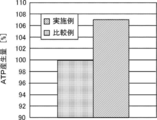
図15は、実施例及び比較例に係る方法で回収された細胞含有構造物におけるATP(adenosine triphosphate:アデノシン三リン酸)産生量を比較した結果を示すグラフである。なお、ATP産生量の測定には、BioTek社製 Cytation 5(Cytationは登録商標) CYT5MPVを用いた。図15において、比較例に係る細胞含有構造物におけるATP産生量を100%としている。図15に示すように、実施例に係る細胞含有構造物の方が、ATP産生量が多くなった。すなわち、実施例に係る細胞回収方法によれば、比較例に係る細胞回収方法と比較して細胞へのダメージが小さいと考えられる。
なお、2019年2月18日に出願された日本国特許出願2019-026960の開示は、その全体が参照により本明細書に取り込まれる。また、本明細書に記載された全ての文献、特許出願および技術規格は、個々の文献、特許出願、および技術規格が参照により取り込まれることが具体的かつ個々に記された場合と同程度に、本明細書中に参照により取り込まれる。
Claims (9)
- 細胞が収容された培養容器を、前記培養容器の底面と交差する回転軸の周りに回転させ、
前記培養容器の回転前または回転中に、前記培養容器の底面の回転中心に液体を吐出し、
前記培養容器の底面の外縁部に前記細胞を偏在させ、
前記培養容器の底面の外縁部に偏在する前記細胞を回収する
細胞回収方法。 - 前記培養容器の外縁部において作用する相対遠心力が前記培養容器の底面の外縁部に前記細胞を偏在させることが可能な最小限の大きさより大きく、且つ前記細胞の前記培養容器からの飛び出しが生じない最大限の大きさよりも小さい
請求項1に記載の細胞回収方法。 - 前記培養容器を前記回転軸の周りに回転させながら、前記培養容器の底面の外縁部に対応する位置に配置された吸引口から前記細胞を吸引することにより前記細胞を回収する
請求項1または請求項2に記載の細胞回収方法。 - 前記回転軸が、前記培養容器の底面の中心部に対応する位置に配置されている
請求項1から請求項3のいずれか1項に記載の細胞回収方法。 - 前記培養容器の底面には、細胞を収容するための複数の凹部が設けられている
請求項1から請求項4のいずれか1項に記載の細胞回収方法。 - 培養容器を、前記培養容器の底面と交差する回転軸の周りに回転させるための回転駆動部と、
前記培養容器の底面の外縁部に対応する位置に配置された吸引口から前記培養容器に収容された細胞を吸引することにより回収する回収部と、
前記培養容器の底面の回転中心に液体を吐出する液体吐出部と、
を含む細胞回収装置。 - 前記培養容器の底面の外縁部において作用する相対遠心力が前記培養容器の底面の外縁部に前記細胞を偏在させることが可能な最小限の大きさより大きく、且つ前記細胞の前記培養容器からの飛び出しが生じない最大限の大きさよりも小さい
請求項6に記載の細胞回収装置。 - 前記回転駆動部は、前記回収部において前記細胞を回収している間、前記培養容器を前記回転軸の周りに回転させる
請求項6または請求項7に記載の細胞回収装置。 - 前記回転軸が、前記培養容器の底面の中心部に対応する位置に配置されている
請求項6から請求項8のいずれか1項に記載の細胞回収装置。
Priority Applications (1)
| Application Number | Priority Date | Filing Date | Title |
|---|---|---|---|
| JP2021501765A JP7139510B2 (ja) | 2019-02-18 | 2020-01-28 | 細胞回収方法及び細胞回収装置 |
Applications Claiming Priority (2)
| Application Number | Priority Date | Filing Date | Title |
|---|---|---|---|
| JP2019026960 | 2019-02-18 | ||
| JP2019-026960 | 2019-02-18 |
Publications (1)
| Publication Number | Publication Date |
|---|---|
| WO2020170727A1 true WO2020170727A1 (ja) | 2020-08-27 |
Family
ID=72144792
Family Applications (1)
| Application Number | Title | Priority Date | Filing Date |
|---|---|---|---|
| PCT/JP2020/002925 Ceased WO2020170727A1 (ja) | 2019-02-18 | 2020-01-28 | 細胞回収方法及び細胞回収装置 |
Country Status (2)
| Country | Link |
|---|---|
| JP (1) | JP7139510B2 (ja) |
| WO (1) | WO2020170727A1 (ja) |
Citations (4)
| Publication number | Priority date | Publication date | Assignee | Title |
|---|---|---|---|---|
| JP2005237274A (ja) * | 2004-02-26 | 2005-09-08 | Kenichiro Hatake | 細胞培養方法、チャンバ及びそれを利用した細胞培養装置 |
| JP2010148451A (ja) * | 2008-12-25 | 2010-07-08 | Olympus Corp | 細胞処理装置 |
| JP2012055226A (ja) * | 2010-09-08 | 2012-03-22 | Olympus Corp | 細胞処理装置 |
| JP2017201946A (ja) * | 2016-05-12 | 2017-11-16 | パナソニック株式会社 | 細胞培養装置および細胞培養方法 |
-
2020
- 2020-01-28 WO PCT/JP2020/002925 patent/WO2020170727A1/ja not_active Ceased
- 2020-01-28 JP JP2021501765A patent/JP7139510B2/ja active Active
Patent Citations (4)
| Publication number | Priority date | Publication date | Assignee | Title |
|---|---|---|---|---|
| JP2005237274A (ja) * | 2004-02-26 | 2005-09-08 | Kenichiro Hatake | 細胞培養方法、チャンバ及びそれを利用した細胞培養装置 |
| JP2010148451A (ja) * | 2008-12-25 | 2010-07-08 | Olympus Corp | 細胞処理装置 |
| JP2012055226A (ja) * | 2010-09-08 | 2012-03-22 | Olympus Corp | 細胞処理装置 |
| JP2017201946A (ja) * | 2016-05-12 | 2017-11-16 | パナソニック株式会社 | 細胞培養装置および細胞培養方法 |
Also Published As
| Publication number | Publication date |
|---|---|
| JP7139510B2 (ja) | 2022-09-20 |
| JPWO2020170727A1 (ja) | 2021-11-25 |
Similar Documents
| Publication | Publication Date | Title |
|---|---|---|
| US8152707B2 (en) | Bio cell cleaning centrifuge and bio cell cleaning rotor used in the same | |
| EP2590695B1 (en) | Apparatus and methods relating to collecting and processing human biological material containing adipose | |
| US9388377B2 (en) | Regenerative cell extraction unit and regenerative cell extraction system | |
| JP2020093257A (ja) | 脂肪組織遠心分離機および使用方法 | |
| CN104168992B (zh) | 搅拌装置以及具备其的吐出装置和吐出方法 | |
| CN104011197B (zh) | 对象物分选装置以及对象物分选方法 | |
| CN109415675B (zh) | 使用冲击波或机械冲击分离、解离和/或裂解细胞的方法 | |
| JP6450476B2 (ja) | 対象物移動方法及び装置 | |
| CN103418503B (zh) | 带导流板遮掩物的离心腔室 | |
| WO2018123663A1 (ja) | 細胞培養基材及びその製造方法 | |
| CN113414013A (zh) | 细胞离心装置及细胞离心、清洗与培养方法 | |
| JP7139510B2 (ja) | 細胞回収方法及び細胞回収装置 | |
| CN115956196B (zh) | 离心机及离心机用转子 | |
| JP2010158203A (ja) | 撹拌機および細胞分離装置 | |
| EP3492578B1 (en) | Method for harvesting cultured cells from three-dimensional porous scaffold | |
| JP7776889B2 (ja) | 細胞遠心装置、並びに細胞遠心、洗浄及び培養方法 | |
| JP2024082564A (ja) | 細胞培養装置及び細胞培養方法 | |
| JP6456058B2 (ja) | 細胞培養のためのガス透過性膜を備えた遠心分離チャンバ | |
| WO2012111684A1 (ja) | 自動細胞ハンドリングロボットにおける泡沫除去デバイス | |
| JP7486160B2 (ja) | 細胞培養装置および細胞培養方法 | |
| EP3079823B1 (en) | Cell dispensing system and method | |
| JP2016036274A (ja) | 細胞剥離方法、細胞剥離装置、及び、細胞培養システム | |
| JP2012055226A (ja) | 細胞処理装置 | |
| JP2024546813A5 (ja) | ||
| KR102290830B1 (ko) | 효소를 사용하지 않고 생체조직에서 기질세포를 분리하는 방법 및 장치 |
Legal Events
| Date | Code | Title | Description |
|---|---|---|---|
| 121 | Ep: the epo has been informed by wipo that ep was designated in this application |
Ref document number: 20759651 Country of ref document: EP Kind code of ref document: A1 |
|
| ENP | Entry into the national phase |
Ref document number: 2021501765 Country of ref document: JP Kind code of ref document: A |
|
| NENP | Non-entry into the national phase |
Ref country code: DE |
|
| 122 | Ep: pct application non-entry in european phase |
Ref document number: 20759651 Country of ref document: EP Kind code of ref document: A1 |