WO2020170705A1 - 撮像装置、電子機器、および撮像方法 - Google Patents
撮像装置、電子機器、および撮像方法 Download PDFInfo
- Publication number
- WO2020170705A1 WO2020170705A1 PCT/JP2020/002243 JP2020002243W WO2020170705A1 WO 2020170705 A1 WO2020170705 A1 WO 2020170705A1 JP 2020002243 W JP2020002243 W JP 2020002243W WO 2020170705 A1 WO2020170705 A1 WO 2020170705A1
- Authority
- WO
- WIPO (PCT)
- Prior art keywords
- subject
- image data
- unit
- image
- memory
- Prior art date
- Legal status (The legal status is an assumption and is not a legal conclusion. Google has not performed a legal analysis and makes no representation as to the accuracy of the status listed.)
- Ceased
Links
Images



Classifications
-
- G—PHYSICS
- G06—COMPUTING OR CALCULATING; COUNTING
- G06V—IMAGE OR VIDEO RECOGNITION OR UNDERSTANDING
- G06V40/00—Recognition of biometric, human-related or animal-related patterns in image or video data
- G06V40/20—Movements or behaviour, e.g. gesture recognition
- G06V40/23—Recognition of whole body movements, e.g. for sport training
-
- G—PHYSICS
- G06—COMPUTING OR CALCULATING; COUNTING
- G06V—IMAGE OR VIDEO RECOGNITION OR UNDERSTANDING
- G06V40/00—Recognition of biometric, human-related or animal-related patterns in image or video data
- G06V40/20—Movements or behaviour, e.g. gesture recognition
-
- G—PHYSICS
- G03—PHOTOGRAPHY; CINEMATOGRAPHY; ANALOGOUS TECHNIQUES USING WAVES OTHER THAN OPTICAL WAVES; ELECTROGRAPHY; HOLOGRAPHY
- G03B—APPARATUS OR ARRANGEMENTS FOR TAKING PHOTOGRAPHS OR FOR PROJECTING OR VIEWING THEM; APPARATUS OR ARRANGEMENTS EMPLOYING ANALOGOUS TECHNIQUES USING WAVES OTHER THAN OPTICAL WAVES; ACCESSORIES THEREFOR
- G03B15/00—Special procedures for taking photographs; Apparatus therefor
-
- G—PHYSICS
- G03—PHOTOGRAPHY; CINEMATOGRAPHY; ANALOGOUS TECHNIQUES USING WAVES OTHER THAN OPTICAL WAVES; ELECTROGRAPHY; HOLOGRAPHY
- G03B—APPARATUS OR ARRANGEMENTS FOR TAKING PHOTOGRAPHS OR FOR PROJECTING OR VIEWING THEM; APPARATUS OR ARRANGEMENTS EMPLOYING ANALOGOUS TECHNIQUES USING WAVES OTHER THAN OPTICAL WAVES; ACCESSORIES THEREFOR
- G03B7/00—Control of exposure by setting shutters, diaphragms or filters, separately or conjointly
- G03B7/08—Control effected solely on the basis of the response, to the intensity of the light received by the camera, of a built-in light-sensitive device
- G03B7/091—Digital circuits
-
- G—PHYSICS
- G06—COMPUTING OR CALCULATING; COUNTING
- G06T—IMAGE DATA PROCESSING OR GENERATION, IN GENERAL
- G06T1/00—General purpose image data processing
- G06T1/0007—Image acquisition
-
- G—PHYSICS
- G06—COMPUTING OR CALCULATING; COUNTING
- G06T—IMAGE DATA PROCESSING OR GENERATION, IN GENERAL
- G06T1/00—General purpose image data processing
- G06T1/20—Processor architectures; Processor configuration, e.g. pipelining
-
- G—PHYSICS
- G06—COMPUTING OR CALCULATING; COUNTING
- G06T—IMAGE DATA PROCESSING OR GENERATION, IN GENERAL
- G06T7/00—Image analysis
- G06T7/20—Analysis of motion
-
- G—PHYSICS
- G06—COMPUTING OR CALCULATING; COUNTING
- G06T—IMAGE DATA PROCESSING OR GENERATION, IN GENERAL
- G06T7/00—Image analysis
- G06T7/20—Analysis of motion
- G06T7/215—Motion-based segmentation
-
- G—PHYSICS
- G06—COMPUTING OR CALCULATING; COUNTING
- G06V—IMAGE OR VIDEO RECOGNITION OR UNDERSTANDING
- G06V10/00—Arrangements for image or video recognition or understanding
- G06V10/70—Arrangements for image or video recognition or understanding using pattern recognition or machine learning
- G06V10/74—Image or video pattern matching; Proximity measures in feature spaces
-
- G—PHYSICS
- G06—COMPUTING OR CALCULATING; COUNTING
- G06V—IMAGE OR VIDEO RECOGNITION OR UNDERSTANDING
- G06V10/00—Arrangements for image or video recognition or understanding
- G06V10/96—Management of image or video recognition tasks
-
- H—ELECTRICITY
- H04—ELECTRIC COMMUNICATION TECHNIQUE
- H04N—PICTORIAL COMMUNICATION, e.g. TELEVISION
- H04N23/00—Cameras or camera modules comprising electronic image sensors; Control thereof
- H04N23/60—Control of cameras or camera modules
-
- H—ELECTRICITY
- H04—ELECTRIC COMMUNICATION TECHNIQUE
- H04N—PICTORIAL COMMUNICATION, e.g. TELEVISION
- H04N23/00—Cameras or camera modules comprising electronic image sensors; Control thereof
- H04N23/60—Control of cameras or camera modules
- H04N23/61—Control of cameras or camera modules based on recognised objects
-
- H—ELECTRICITY
- H04—ELECTRIC COMMUNICATION TECHNIQUE
- H04N—PICTORIAL COMMUNICATION, e.g. TELEVISION
- H04N23/00—Cameras or camera modules comprising electronic image sensors; Control thereof
- H04N23/60—Control of cameras or camera modules
- H04N23/62—Control of parameters via user interfaces
-
- H—ELECTRICITY
- H04—ELECTRIC COMMUNICATION TECHNIQUE
- H04N—PICTORIAL COMMUNICATION, e.g. TELEVISION
- H04N23/00—Cameras or camera modules comprising electronic image sensors; Control thereof
- H04N23/60—Control of cameras or camera modules
- H04N23/63—Control of cameras or camera modules by using electronic viewfinders
-
- H—ELECTRICITY
- H04—ELECTRIC COMMUNICATION TECHNIQUE
- H04N—PICTORIAL COMMUNICATION, e.g. TELEVISION
- H04N23/00—Cameras or camera modules comprising electronic image sensors; Control thereof
- H04N23/60—Control of cameras or camera modules
- H04N23/667—Camera operation mode switching, e.g. between still and video, sport and normal or high- and low-resolution modes
-
- H—ELECTRICITY
- H04—ELECTRIC COMMUNICATION TECHNIQUE
- H04N—PICTORIAL COMMUNICATION, e.g. TELEVISION
- H04N23/00—Cameras or camera modules comprising electronic image sensors; Control thereof
- H04N23/60—Control of cameras or camera modules
- H04N23/67—Focus control based on electronic image sensor signals
- H04N23/675—Focus control based on electronic image sensor signals comprising setting of focusing regions
-
- H—ELECTRICITY
- H04—ELECTRIC COMMUNICATION TECHNIQUE
- H04N—PICTORIAL COMMUNICATION, e.g. TELEVISION
- H04N5/00—Details of television systems
- H04N5/76—Television signal recording
- H04N5/91—Television signal processing therefor
-
- G—PHYSICS
- G06—COMPUTING OR CALCULATING; COUNTING
- G06T—IMAGE DATA PROCESSING OR GENERATION, IN GENERAL
- G06T2207/00—Indexing scheme for image analysis or image enhancement
- G06T2207/10—Image acquisition modality
- G06T2207/10016—Video; Image sequence
-
- G—PHYSICS
- G06—COMPUTING OR CALCULATING; COUNTING
- G06T—IMAGE DATA PROCESSING OR GENERATION, IN GENERAL
- G06T2207/00—Indexing scheme for image analysis or image enhancement
- G06T2207/20—Special algorithmic details
- G06T2207/20072—Graph-based image processing
-
- G—PHYSICS
- G06—COMPUTING OR CALCULATING; COUNTING
- G06T—IMAGE DATA PROCESSING OR GENERATION, IN GENERAL
- G06T2207/00—Indexing scheme for image analysis or image enhancement
- G06T2207/20—Special algorithmic details
- G06T2207/20084—Artificial neural networks [ANN]
-
- G—PHYSICS
- G06—COMPUTING OR CALCULATING; COUNTING
- G06T—IMAGE DATA PROCESSING OR GENERATION, IN GENERAL
- G06T2207/00—Indexing scheme for image analysis or image enhancement
- G06T2207/30—Subject of image; Context of image processing
- G06T2207/30196—Human being; Person
-
- G—PHYSICS
- G06—COMPUTING OR CALCULATING; COUNTING
- G06T—IMAGE DATA PROCESSING OR GENERATION, IN GENERAL
- G06T2207/00—Indexing scheme for image analysis or image enhancement
- G06T2207/30—Subject of image; Context of image processing
- G06T2207/30241—Trajectory
Definitions
- the present disclosure relates to an imaging device, an electronic device, and an imaging method.
- an imaging device equipped with a continuous shooting function that enables high-speed continuous shooting of moving subjects to capture the movement of the subject at the moment desired by the user.
- a continuous shooting function that enables high-speed continuous shooting of moving subjects to capture the movement of the subject at the moment desired by the user.
- Patent Document 1 when it is determined that the operation unit for continuous shooting is pressed by the user, continuous shooting is performed at a higher frame speed than the current frame speed, and the operation unit is not pressed. If it is determined that the current frame speed is maintained, an imaging device is described.
- the imaging device may not be able to capture the motion of the subject at the moment desired by the user. Therefore, the present disclosure proposes an imaging device, an electronic device, and an imaging method capable of imaging a momentary motion desired by a user among motions of a subject.
- the imaging device has an imaging unit, a memory, a detection unit, and a determination unit.
- the image capturing unit sequentially captures images of a subject and generates image data.
- the memory stores the image data.
- the detection unit detects the movement of the subject based on the image data.
- the determining unit determines, as image data to be stored in the memory, image data in which the detecting unit detects the movement of the subject in a direction that matches the moving direction of the subject predicted based on the image data.
- FIG. 6 is an operation explanatory diagram of CIS according to the first embodiment. It is explanatory drawing of the high-speed captured image which concerns on the contrast of 1st Embodiment. It is explanatory drawing of the high-speed imaged image which concerns on 1st Embodiment. It is a flow chart which shows an example of processing which CIS concerning a 1st embodiment performs. It is a block diagram which shows schematic structure of the electronic device which concerns on 2nd Embodiment. It is an operation explanatory view of CIS concerning a 2nd embodiment.
- FIG. 1 is a block diagram showing a schematic configuration example of an electronic device according to the first embodiment.
- the electronic device 1 illustrated in FIG. 1 is a device that captures a still image or a moving image, and is, for example, a digital camera, a digital video camera, a tablet terminal having a camera function, a smartphone, or the like.
- the electronic device 1 has a CMOS (Complementary Metal Oxide Semiconductor) image sensor (hereinafter referred to as CIS2), an application processor (hereinafter referred to as AP3), and a display operation unit 4. ..
- CMOS Complementary Metal Oxide Semiconductor
- AP3 Application processor
- the display operation unit 4 is a touch panel liquid crystal display having a function of displaying an image and a function of receiving a touch operation by a user.
- the electronic device 1 may be configured to include a liquid crystal display that displays an image, and an operation switch that receives a touch operation by a user, instead of the display operation unit 4.
- CIS2 is an example of an imaging device that is configured with one chip and captures an image, and outputs the image data of the captured image to AP3.
- the CIS 2 has a high-speed image capturing function of continuously shooting a subject at high speed (hereinafter, referred to as high-speed image capturing) in addition to a function of capturing a normal still image or a moving image.
- the imaging device according to the present disclosure is not limited to the CIS2, and may be another image sensor such as a CCD (Charge Coupled Device) image sensor.
- CCD Charge Coupled Device
- the AP 3 communicates information between the AP control unit 31, which is an example of a processor such as a CPU (Central Processing Unit) that executes various application programs according to the use of the electronic device 1, and the CIS 2, and a communication I/F ( Interface) 32.
- a processor such as a CPU (Central Processing Unit) that executes various application programs according to the use of the electronic device 1, and the CIS 2, and a communication I/F ( Interface) 32.
- a communication I/F Interface
- the AP 3 performs, for example, a correction process and a processing process for the image data input from the CIS 2, and also a display control process for displaying the image data on the display operation unit 4.
- the AP 3 can reproduce the motion of the subject moving at high speed in super slow by displaying the image data of the captured image captured at high speed by the CIS 2 in frame-by-frame manner on the display operation unit 4. ..
- the CIS sequentially and continuously captures a subject, and the image data of the captured image is stored in a memory in time series.
- the electronic device reproduces the image data captured at high speed in super slow, the image data in which the motion of the subject at the moment desired by the user is captured is not stored in the memory. Cannot reproduce the image at the desired moment.
- a general electronic device may not be able to capture an image of the movement of the subject at a moment desired by the user among the movements of the subject.
- the CIS 2 has a configuration capable of capturing the movement of the subject at a moment desired by the user even when the user's operation for starting high-speed imaging is too fast.
- the CIS 2 includes an image pickup unit 5, a memory 6, a communication I/F 7, and a start determination unit 8.
- the image pickup unit 5 includes a light receiving unit 51 and a reading unit 52.
- the light receiving unit 51 includes, for example, an optical system including a zoom lens, a focus lens, a diaphragm, and the like, and a pixel array unit in which unit pixels including light receiving elements such as photodiodes are arranged in a two-dimensional matrix.
- the light receiving unit 51 forms an image of light incident from the outside on the light receiving surface of the pixel array unit by an optical system.
- Each unit pixel of the pixel array section photoelectrically converts the light incident on the light receiving element to readably store charges corresponding to the amount of incident light.
- the reading unit 52 reads a charge accumulated in each unit pixel as a pixel signal and an ADC that generates digital image data by converting an analog pixel signal read by the read circuit into a digital value. (Analog to Digital Converter). The reading unit 52 outputs the generated image data to the start determination unit 8 in image units of one frame.
- the image pickup unit 5 also has an AF (autofocus) function.
- the imaging unit 5 outputs information indicating the position of the focus point in the captured image to the start determination unit 8 when the subject is in focus (focus point) by the AF function.
- the image pickup unit 5 picks up a still image or a moving image when a signal indicating that the user has performed an image pickup operation is input from the display operation unit 4.
- the image capturing unit 5 starts high-speed image capturing when it receives a signal (hereinafter, referred to as high-speed image capturing trigger) indicating that the user has performed a high-speed image capturing start operation from the display operation unit 4.
- the start determination unit 8 deletes the image data captured before the image data that is likely to be captured by the user, out of the image data captured by the image capturing unit 5 at high speed, Image data that is highly likely to be imaged is selectively stored in the memory 6.
- the start determination unit 8 can capture the movement of the subject at the moment desired by the user.
- the start determination unit 8 includes, for example, a microcomputer having a CPU (Central Processing Unit), a ROM (Read Only Memory), a RAM (Random Access Memory), and various circuits.
- the start determination unit 8 includes a specifying unit 81, a predicting unit 82, a detecting unit 83, and a determining unit 84, which function by the CPU executing a program stored in the ROM using the RAM as a work area.
- Part or all of the identification unit 81, the prediction unit 82, the detection unit 83, and the determination unit 84 included in the start determination unit 8 are hardware such as ASIC (Application Specific Integrated Circuit) and FPGA (Field Programmable Gate Array). May be composed of ASIC (Application Specific Integrated Circuit) and FPGA (Field Programmable Gate Array). May be composed of ASIC (Application Specific Integrated Circuit) and FPGA (Field Programmable Gate Array). May be composed of
- the identification unit 81, the prediction unit 82, the detection unit 83, and the determination unit 84 included in the start determination unit 8 execute information processing described below.
- the internal configuration of the start determination unit 8 is not limited to the configuration shown in FIG. 1 and may be another configuration as long as it is a configuration for performing information processing described later.
- the identifying unit 81 identifies the subject based on the image data, and outputs information indicating the position of the subject in the image and the image data to the predicting unit 82 and the detecting unit 83.
- the identifying unit 81 identifies the subject by determining the composition of the image by DNN processing using DNN (Deep Neural Network) and determining the ROI (Region of Interest) region in which the subject appears from the determined composition, for example. ..
- the identifying unit 81 outputs information indicating the position of the ROI region in the image in which the subject is identified and the image data in which the subject is identified to the predicting unit 82 and the detecting unit 83.
- the identifying unit 81 can identify the subject using various neural networks such as RNN (Recurrent Neural Networks) and CNN (Convolutional Neural Networks), not limited to DNNs.
- the specifying unit 81 may be configured to specify the subject using a learning model learned by various other machine learning such as a decision tree or a support vector machine.
- the prediction unit 82 predicts the moving direction of the subject by performing DNN processing using DNN on the image data, for example.
- the prediction unit 82 can predict the moving direction of the subject using various neural networks such as RNN and CNN, not limited to DNN.
- the prediction unit 82 may be configured to predict the moving direction of the subject using a learning model learned by various other machine learning such as a decision tree and a support vector machine. For example, when the subject is a baseball batter, the predicting unit 82 moves in the direction in which the swinging bat moves, when the subject is a car or train, the traveling direction, and when the subject is a person running, the limbs and hair move. Predict the direction, the method of flapping wings if the subject is a bird, etc.
- a learning model learned by various other machine learning such as a decision tree and a support vector machine. For example, when the subject is a baseball batter, the predicting unit 82 moves in the direction in which the swinging bat moves, when the subject is a car or train, the traveling direction, and when the subject is a person running, the limbs and hair move. Predict the direction, the method of flapping wings if the subject is a bird, etc.
- the prediction unit 82 outputs information indicating the predicted moving direction of the subject to the determination unit 84.
- the detection unit 83 detects the movement of the subject based on the time-series image data, and outputs information indicating the movement of the subject (including the amount of movement and the moving direction) to the determination unit 84.
- the determining unit 84 determines the image data to be stored in the memory 6 based on the information input from the predicting unit 82 and the detecting unit 83, and outputs the image data determined to be stored to the memory 6 to store the image data. At this time, the determining unit 84 determines the image data in which the motion that matches the moving direction of the subject predicted by the predicting unit 82 is detected by the detecting unit 83 as the image data to be stored in the memory 6.
- image data that does not need to be captured at high speed because the user's operation for starting high-speed imaging is too fast and the orientation predicted by the prediction unit 82 due to camera shake or the like is stored. Does not store image data in which the subject moves in different directions.
- the memory 6 also stores image data in which the subject has moved in a direction that matches the direction predicted by the prediction unit 82, and which is likely to be desired by the user for high-speed imaging. As a result, the CIS 2 can capture the movement of the subject at the moment desired by the user even when the user's operation for starting high-speed imaging is too fast.
- the memory 6 is, for example, a storage device such as a flash memory, and stores the image data of the captured image input from the start determination unit 8 in time series.
- the communication I/F 7 receives an image data acquisition request from the AP 3, the communication I/F 7 outputs the image data stored in the memory 6 to the AP 3.
- the AP control unit 31 outputs the image data input from the CIS 2 via the communication I/F 32 to the display operation unit 4 for display.
- the AP control unit 31 outputs an image data acquisition request to the CIS 2 via the communication I/F 32 and acquires the image data from the CIS 2 when the display operation unit 4 receives an image display operation by the user, for example. Then, it is displayed on the display operation unit 4.
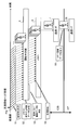
- FIG. 2 is an operation explanatory diagram of the CIS according to the present disclosure.
- the subject is specified from the preview image Pre by the start determination unit 8 before the high-speed imaging is started (step S1).
- the start determination unit 8 acquires the high-speed imaged image data from the image capturing unit 5, and based on the image data before being stored in the memory 6. , Image data to be stored in the memory 6 is determined (step S2). At this time, the start determination unit 8 determines the image data in which the moving direction of the subject matches the predicted direction as the image data to be stored in the memory 6.
- the start determination unit 8 The image data that is not saved is deleted (step S3).
- the start determination unit 8 selectively outputs the image data determined to be stored in the memory 6 out of all the image data acquired from the imaging unit 5 to the memory 6 and starts recording (step S4).
- the CIS 2 does not record in the memory 6 image data that does not require high-speed imaging, such as image data in which the subject does not move in the initial image of high-speed imaging. It can be effectively used for recording data.
- the CIS 2 outputs image data from the memory 6 to the communication I/F 32 of the AP 3 via the communication I/F 7 of the CIS 2 (step S5). ..
- the AP 3 causes the display operation unit 4 to display the high-speed imaged image data input from the CIS 2 at a frame rate slower than the image capturing speed, so that the subject's movement at the moment desired by the user Images that show motion can be played back in super slow mode.
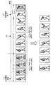
- FIG. 3 is an explanatory diagram of a high-speed captured image according to the contrast of the present disclosure.
- FIG. 4 is an explanatory diagram of a high-speed captured image according to the present disclosure.
- the number of image frames that can be stored in the memory 6 is 7 frames, which is extremely smaller than the actual number.
- the swinging motion of a baseball bat includes a series of actions of take back, swing, and follow through.
- the CIS 2 starts high-speed imaging at time t1 and ends high-speed imaging at time t2 when the image of the seventh frame is captured.
- the reproduced image is, as shown in the lower part of FIG. 3, most of the reproduced image is the image of the subject being taken back, which is important for the user. The image during the swing and the moment of impact are not shown.
- the start determination unit 8 when the image is erased by the start determination unit 8, as shown in the upper part of FIG. 4, the start determination unit 8 does not move the subject after the image of the first frame is captured at time t1. The image of the takeback of 2 to 4 frames is determined as the image data not stored in the memory 6. Then, the start determination unit 8 erases the image of 2 to 4 frames which is determined not to be stored.
- the memory 6 still has only one frame of image stored, so the remaining six frames of image can be stored. Then, since the subject enters the swing motion from the fifth frame, the movement of the subject in the direction that matches the predicted direction is detected. Therefore, the start determination unit 8 determines that the image of 5 to 10 frames is the image to be stored in the memory 6, stores the image data of 5 to 10 frames in the memory 6, and the high-speed imaging ends at time t3.
- the reproduced image includes images from the start to the end of the swing as shown in the lower part of FIG. 4, and includes the moment of impact desired by the user. Has been.
- the reproduced image shown in the lower part of Fig. 4 is an image in which 2 to 4 frame images are thinned out, so it is not a super-throw image that accurately represents the actual movement of the subject.
- the thinned out images of 2 to 4 frames are images in which the subject hardly moves, and are not images in the period in which high-speed imaging is required.
- the reproduced image shown in the lower part of FIG. 4 can be said to be an image that has achieved the purpose of high-speed imaging from the user's viewpoint, and is a super-slow image in which the shooting time is extended as the user senses. ..
- the CIS2 even when the user's operation for starting high-speed imaging is too fast, the motion of the subject at the moment desired by the user in the motion of the subject can be captured.
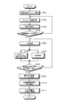
- FIG. 5 is a flowchart showing an example of processing executed by the CIS 2 according to the present disclosure.
- the CIS 2 executes the processing shown in FIG. 5 when the electronic device 1 is in the high-speed imaging mode. Specifically, in the CIS2, when the electronic device enters the high-speed imaging mode, the imaging unit 5 first starts the high-speed imaging preview as shown in FIG. 5 (step S101). Here, the imaging unit 5 captures the preview image at a lower speed than the high-speed imaging.
- the start determination unit 8 acquires the preview image (step S102) and identifies the subject (step S103). Then, the imaging unit 5 determines whether or not a high-speed imaging trigger has been received (step S104).
- step S104 determines that the high-speed imaging trigger has not been received (step S104, No).
- the process proceeds to step S102.
- the image capturing unit 5 determines that the high-speed image capturing trigger has been received (Yes in step S104)
- the high-speed image capturing is started and one image is captured (step S105).
- the start determination unit 8 predicts the direction in which the subject in the image moves by the DNN (step S106). Further, the start determination unit 8 detects the movement of the subject in the image in parallel with the process of step S106 (step S107).
- step S108 determines whether or not the moving direction of the subject matches the prediction.
- the process proceeds to step S105.
- the start determination unit 8 determines that the image data in which the movement is detected is the image data to be stored (step S109). Then, the start determination unit 8 starts saving the high-speed captured image (step S110). Then, the imaging unit 5 performs imaging up to the upper limit of the capacity of the memory 6 (step S111), and ends the process.
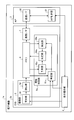
- FIG. 6 is a block diagram showing the configuration of the electronic device according to the second embodiment.
- the electronic device 1a according to the second embodiment has a configuration in which the image pickup unit 5 in the CIS 2a outputs the image data of the picked-up image to the memory 6 and stores the image data, and the start determination unit 8a. 1 is different from the electronic device 1 shown in FIG. 1, and the other structure is the same as that shown in FIG.
- the imaging unit 5 of the CIS 2a sequentially outputs the image data captured at high speed to the memory 6 to store the image data.
- the start determination unit 8a includes a specification unit 81a, a prediction unit 82a, a detection unit 83a, and a determination unit 84a.
- the specifying unit 81a acquires image data from the memory 6 and specifies a subject based on the image data by DNN, for example. Then, the identifying unit 81a outputs information indicating the position of the subject in the image to the prediction unit 82a and the detection unit 83a.
- the prediction unit 82a acquires image data from the memory 6 in time series, and predicts the moving direction of the subject by, for example, DNN processing using DNN.
- the prediction unit 82a outputs information indicating the predicted moving direction of the subject to the determination unit 84a.
- the detection unit 83a acquires image data in time series from the memory 6, detects the movement of the subject based on the time-series image data, and determines information indicating the movement of the subject (including the amount of movement and the moving direction). It is output to the unit 84a.
- the determining unit 84a determines the image data to be stored in the memory 6 (leave without being erased) based on the information input from the predicting unit 82a and the detecting unit 83a.
- the determining unit 84a determines the image data in which the motion that matches the moving direction of the subject predicted by the predicting unit 82a is detected by the detecting unit 83a as the image data to be stored in the memory 6.
- the determining unit 84a determines that the image data in which the motion that matches the moving direction of the subject predicted by the predicting unit 82a is not detected by the detecting unit 83a is an image that is not stored in the memory 6, and erases it from the memory 6. ..
- image data that does not need to be captured at high speed because the user's operation for starting high-speed imaging is too fast and the orientation predicted by the prediction unit 82a due to camera shake or the like is stored. Does not store image data in which the subject moves in different directions.
- the memory 6 stores image data in which the subject has moved in a direction that matches the direction predicted by the prediction unit 82a, and which is likely to be desired by the user for high-speed imaging.
- the CIS 2a can capture the movement of the subject at the moment desired by the user even when the user's operation for starting high-speed imaging is too fast.
- FIG. 7 is an operation explanatory diagram of the CIS according to the present disclosure. Although two memories 6 are shown in FIG. 2, this is to facilitate understanding of the operation of the CIS 2a, and the two memories 6 in FIG. 2 are physically the same. It is a thing.
- the start determination unit 8 first identifies the subject from the preview image Pre before starting high-speed imaging (step S11). After that, when the CIS 2 receives the high-speed image capturing trigger and starts the high-speed image capturing, the CIS 2 outputs the high-speed imaged image data from the image capturing unit 5 to the memory 6 and stores the image data in the memory 6 (step S12).
- the start determination unit 8 reads the image data from the memory 6 (step S13). Then, the start determination unit 8 determines the image data to be stored in the memory 6 based on the image data stored in the memory 6 (step S14). At this time, the start determination unit 8 determines the image data in which the moving direction of the subject matches the predicted direction as the image data to be stored in the memory 6.
- the start determination unit 8 deletes the image data determined not to be saved from the memory 6 (step S15).
- recording is started from the image data determined to be stored in the memory 6 by the start determination unit 8 (step S16).
- the CIS 2 deletes from the memory 6 image data that does not require high-speed imaging, such as image data in which the subject does not move in the image at the beginning of high-speed imaging. It can be effectively used for recording image data desired to be captured.
- the CIS 2 outputs image data from the memory 6 to the communication I/F 32 of the AP 3 via the communication I/F 7 of the CIS 2 when displaying the high-speed captured image on the display operation unit 4 (step S17). ..
- the AP 3 causes the display operation unit 4 to display the high-speed imaged image data input from the CIS 2 at a frame rate slower than the image capturing speed, so that the subject's movement at the moment desired by the user Images that show motion can be played back in super slow mode.
- the identifying units 81 and 81a include the case where a plurality of moving objects exist in the captured image.
- the identifying units 81 and 81a identify an object appearing in the center of the image as a subject.
- the identifying units 81 and 81a can identify the moving body that is highly likely to be desired by the user as an object when a plurality of moving bodies are present in the captured image.
- the specifying units 81 and 81a specify the object selected from the image by the user as a subject.
- the specifying unit 81 specifies the object selected by the touch operation by the user in the preview image displayed on the display operation unit 4 as the subject. Accordingly, the identifying units 81 and 81a can identify the moving body as a subject even if the moving body that the user desires to capture is in a position other than the center of the image.
- the specifying units 81 and 81a can also exclude the object selected from the image by the user as a subject to be specified.
- the user selects and operates the specified object displayed on the display operation unit 4 to specify the specifying unit. It can be excluded from the targets to be specified as the subject by 81 and 81a.
- the specifying units 81 and 81a specify the object closest to the autofocus point as the subject when the AF function is operating. Accordingly, the identifying units 81 and 81a can identify a moving object that is highly likely to be desired by the user as an object.
- the CIS 2, 2a can be provided with a storage unit for storing image data of an object to be specified as a subject by the specifying units 81, 81a.
- the CIS 2, 2a causes the user to previously register and store the image data of the face or the object of the person who is the candidate of the subject in the storage unit.
- the identifying units 81 and 81a identify the subject based on the image data stored in the storage unit. For example, the identifying units 81 and 81a acquire the feature amount of each divided area obtained by dividing the captured image, and use the similarity between the feature amount acquired from the captured image and the feature amount of the image data stored in the storage. A score is calculated, and an object in a divided area with a high score is specified as a subject. Thereby, the specifying units 81 and 81a can specify an object, which is highly likely to be an object whose image data is registered by the user in advance, as a subject.
- the CIS 2 and 2a have a plurality of modes in which the types of objects to be specified as subjects are different. Then, the specifying units 81 and 81a specify an object according to the mode as a subject. For example, the specifying units 81 and 81a specify only a person as a subject when the sports mode is selected by the user, and register only animals as the subject when the animal mode is selected. Thereby, the specifying units 81 and 81a can specify not a specific object but an arbitrary object included in the type desired by the user as the subject.
- the identifying units 81 and 81a can also be provided with AI (artificial intelligence) that estimates an object that is likely to move in the captured image.
- AI artificial intelligence
- the identifying units 81 and 81a identify the object determined to have the highest possibility of movement due to AI as the subject. Accordingly, the identifying units 81 and 81a can identify an object that is likely to move and that the user wants to capture as a subject, even when the user does not select a mode or designates an object.
- the identifying units 81 and 81a determine a person to be identified as a subject based on at least one of age and sex of the persons in the image. For example, the identifying units 81 and 81a determine the person to be identified as the subject by setting the priority of the child to be high, the priority of the woman to be medium, and the priority of the man to be low. The priority for age and sex can be arbitrarily changed. As a result, the specifying units 81 and 81a can specify a person according to the taste of the user as a subject.
- the identifying units 81 and 81a identify, as a subject, an object that is continuously captured in the preview image for a predetermined time or longer. Accordingly, the identifying units 81 and 81a can identify a moving object that is highly likely to be desired by the user to capture an image at a definite moment, as a subject.
- the CIS2, 2a outputs the image stored in the memory 6 to the AP3, acquires the subject specified by the specifying units 81, 81a provided in the AP3 from the AP3, and performs the same procedure as the above-described procedure in the memory 6 Determine the image data to save in.
- the identifying units 81 and 81a are provided on the AP3 side, the image data that is captured at high speed by the image capturing unit 5 needs to be output to the AP3, and thus the power consumption of the CIS2 and 2a increases. Therefore, it is desirable that the identifying units 81 and 81a be provided on the CIS 2, 2a side.
- each component of each illustrated device is functionally conceptual, and does not necessarily have to be physically configured as illustrated. That is, the specific form of distribution/integration of each device is not limited to that shown in the figure, and all or part of the device may be functionally or physically distributed/arranged in arbitrary units according to various loads and usage conditions. It can be integrated and configured.
- the identifying unit 81, the predicting unit 82, the detecting unit 83, and the determining unit 84 illustrated in FIG. 1 may be integrated.
- the CIS 2, 2a has an image pickup unit 5, a memory 6, and decision units 84, 84a.
- the image capturing section 5 captures images of a subject successively and sequentially to generate image data.
- the memory 6 stores image data.
- the detection units 83 and 83a detect the movement of the subject based on the image data.
- the determination units 84 and 84a determine the image data in which the movement of the subject in the direction that matches the moving direction of the subject predicted based on the image data is detected by the detection units 83 and 83a as image data to be stored in the memory 6. To do.
- the CIS 2, 2a secures an empty area in the memory 6 by selectively storing, in the memory 6, the image data determined to be saved by the determining units 84, 84a out of all the image data, and the movement of the subject. It is possible to capture the motion of the moment desired by the user.
- the determining unit 84 determines the image data to be stored in the memory 6 based on the image data before being stored in the memory 6, and stores the image data determined to be stored in the memory 6 by storing it.
- the CIS 2 can secure a free area in the memory 6 before storing the image data in the memory 6.
- the determining unit 84a determines the image data to be stored in the memory 6 based on the image data after being stored in the memory 6, and deletes the image data other than the image data determined to be stored from the memory 6.
- the CIS 2a can secure a free area in the memory 6 after storing the image data in the memory 6.
- the CISs 2 and 2a also include prediction units 82 and 82a that predict the moving direction of the subject based on the image data.
- prediction units 82, 82a that predict the moving direction of the subject based on the image data.
- the prediction units 82 and 82a predict the moving direction of the subject by the DNN process using the DNN. Thereby, the prediction units 82 and 82a can accurately predict the moving direction of the subject.
- the CISs 2 and 2a have identification units 81 and 81a that identify a subject from image data. Accordingly, the prediction units 82 and 82a can predict the moving direction of the subject that is highly likely to be desired by the user when there are a plurality of moving objects in the captured image. In addition, the detection units 83 and 83a can detect the movement of the subject that is highly likely to be desired by the user when a plurality of moving objects are present in the captured image.
- the specifying units 81 and 81a specify an object appearing in the center of the image as a subject.
- the identifying units 81 and 81a can identify a moving object that is highly likely to be desired by the user as an object when a plurality of moving objects are present in the captured image.
- the specifying units 81 and 81a specify the object selected from the image by the user as a subject.
- the identifying units 81 and 81a can identify the moving body as a subject even if the moving body that the user desires to capture appears in a position other than the center of the image.
- the identifying units 81 and 81a exclude the object selected from the image by the user as a subject to be identified. Accordingly, the identifying units 81 and 81a can exclude the automatically identified subject from the subject candidates when the automatically identified subject is not the object intended by the user.
- the specifying units 81 and 81a specify an object close to the focus point of autofocus as a subject.
- the identifying units 81 and 81a can identify, as the subject, a moving body that is highly likely to be imaged by the user who starts high-speed imaging when the focus point is in focus.
- the CISs 2 and 2a also include a storage unit that stores image data of an object that the specifying units 81 and 81a specify as a subject.
- the identifying units 81 and 81a identify the subject based on the image data stored in the storage unit. Thereby, the specifying units 81 and 81a can specify an object, which is highly likely to be an object whose image data is registered by the user in advance, as a subject.
- the CISs 2 and 2a have a plurality of modes in which the types of objects to be identified as objects by the identifying units 81 and 81a are different.
- the identifying units 81 and 81a identify an object according to the mode as a subject.
- the specifying units 81 and 81a can specify not a specific object but an arbitrary object included in the type desired by the user as the subject.
- the identifying units 81 and 81a identify, as a subject, an object determined to have a high possibility of moving in the image by artificial intelligence. Accordingly, the identifying units 81 and 81a can identify an object that is likely to move and that the user wants to capture as a subject, even when the user does not select a mode or designates an object.
- the identifying units 81 and 81a determine the person to be identified as the subject based on the age and/or sex of the person. As a result, the specifying units 81 and 81a can specify a person according to the taste of the user as a subject.
- the identifying units 81 and 81a identify, as a subject, an object that is continuously captured for a predetermined time or longer in the preview image captured by the image capturing unit 5 before high-speed image capturing by the image capturing unit 5 is started. Accordingly, the identifying units 81 and 81a can identify a moving object that is highly likely to be desired by the user to capture an image at a definite moment, as a subject.
- the electronic devices 1 and 1a include CISs 2 and 2a.
- the CIS 2, 2a has an image pickup section 5, a memory 6, detection sections 83, 83a, and determination sections 84, 84a.
- the image capturing section 5 captures images of a subject successively and sequentially to generate image data.
- the memory 6 stores image data.
- the detection units 83 and 83a detect the movement of the subject based on the image data.
- the determining units 84 and 84a determine the image data in which the movement of the subject in the direction that matches the moving direction of the subject predicted based on the image data is detected by the detecting units 83 and 83a as image data to be stored in the memory. To do.
- the CIS 2, 2a secures an empty area in the memory 6 by selectively storing, in the memory 6, the image data determined to be saved by the determining units 84, 84a out of all the image data, and the movement of the subject. It is possible to capture the motion of the moment desired by the user.
- the CIS 2 and 2a sequentially and continuously capture images of a subject to generate image data, detect the movement of the subject based on the image data, and match the moving direction of the subject predicted based on the image data.
- the image data in which the movement of the subject in the moving direction is detected is determined as the image data to be stored in the memory 6.
- the CIS 2 and 2a can capture the motion of the subject at the moment desired by the user.
- An image capturing unit that sequentially captures images of a subject and generates image data
- a memory for storing the image data
- a detection unit that detects the movement of the subject based on the image data
- a determination unit that determines the image data detected by the detection unit as the image data to be stored in the memory, the movement of the subject in a direction that matches the movement direction of the subject predicted based on the image data.
- Imaging device (2)
- the determining unit is The image data to be stored in the memory is determined based on the image data before being stored in the memory, and the image data determined to be stored is stored in the memory and stored. apparatus.
- the determining unit is The image data to be saved in the memory is determined based on the image data after being stored in the memory, and the image data other than the image data determined to be saved is deleted from the memory (1).
- Imaging device. (4) The imaging device according to any one of (1) to (3), further including: a prediction unit that predicts a moving direction of the subject based on the image data. (5) The prediction unit is The imaging device according to (4), wherein the moving direction of the subject is predicted by a DNN process using a DNN (Deep Neural Network). (6) The image pickup apparatus according to any one of (1) to (5), further including a specifying unit that specifies the subject from the image data.
- the specific unit is The imaging device according to (6), wherein an object appearing in the center of the image is specified as a subject.
- the specific unit is The imaging device according to (6) or (7), wherein an object selected by the user from the image is specified as the subject.
- the specific unit is The imaging device according to any one of (6) to (8), wherein an object selected by the user from the image is excluded from a target to be identified as the subject.
- the specific unit is The imaging device according to any one of (6) to (9), wherein an object close to a focus point of autofocus is specified as a subject.
- the specific unit is The imaging device according to any one of (6) to (10), wherein the subject is specified based on the image data stored in the storage unit.
- the specific unit is The imaging device according to any one of (6) to (11), wherein an object according to the mode is specified as a subject.
- the specific unit is The image pickup apparatus according to any one of (6) to (12), wherein an object determined to have a high possibility of movement in the image by artificial intelligence is specified as a subject.
- the specific unit is The imaging device according to any one of (6) to (13), wherein when a plurality of people are included in the image, the person to be identified as a subject is determined based on the age and/or sex of the person.
- the specific unit is The object specified in any one of (6) to (14) is specified as an object, which is continuously photographed for a predetermined time or longer in a preview image captured by the image capturing unit before high-speed image capturing by the image capturing unit is started. Imaging device.
- An image capturing unit that sequentially captures images of a subject and generates image data, A memory for storing the image data, A detection unit that detects the movement of the subject based on the image data, A determining unit that determines the image data detected by the detecting unit as the image data to be stored in the memory when the subject moves in a direction that matches the moving direction of the subject predicted based on the image data.
- An electronic device having an imaging device.
- Image of the subject is taken in sequence to generate image data, Detecting the movement of the subject based on the image data, An image pickup method in which image data in which the movement of the subject in a direction that matches the moving direction of the subject predicted based on the image data is detected is determined as image data to be stored in a memory.
Landscapes
- Engineering & Computer Science (AREA)
- Multimedia (AREA)
- Physics & Mathematics (AREA)
- General Physics & Mathematics (AREA)
- Theoretical Computer Science (AREA)
- Signal Processing (AREA)
- Computer Vision & Pattern Recognition (AREA)
- Health & Medical Sciences (AREA)
- General Health & Medical Sciences (AREA)
- Human Computer Interaction (AREA)
- Psychiatry (AREA)
- Social Psychology (AREA)
- Artificial Intelligence (AREA)
- Computing Systems (AREA)
- Databases & Information Systems (AREA)
- Evolutionary Computation (AREA)
- Medical Informatics (AREA)
- Software Systems (AREA)
- Studio Devices (AREA)
- Exposure Control For Cameras (AREA)
- Television Signal Processing For Recording (AREA)
Abstract
被写体の動きの中でユーザが所望する瞬間の動きを撮像することができる撮像装置および電子機器を提供すること。本開示に係る撮像装置の一例であるCIS(2)は、撮像部(5)と、メモリ(6)と、検出部(83)と、決定部(84)とを有する。撮像部(5)は、順次連続して被写体の画像を撮像して画像データを生成する。メモリ(6)は、画像データを記憶する。検出部(83)は、画像データに基づいて被写体の動きを検出する。決定部(84)は、画像データに基づいて予測された被写体の動く向きと一致する向きへの被写体の動きが検出部によって検出された画像データをメモリに保存する画像データと決定する。
Description
本開示は、撮像装置、電子機器、および撮像方法に関する。
動く被写体を高速連写することによって、被写体の動きの中でユーザが所望する瞬間の動きを撮像可能とする連写機能を備えた撮像装置がある。例えば、特許文献1には、連写用の操作部がユーザによって押されていると判断した場合に、現在のコマ速よりも高速のコマ速で連写を行い、操作部が押されていないと判断した場合に、現在のコマ速を維持する制御を行う撮像装置が記載されている。
しかしながら、撮像装置は、高速連写を行う場合に、被写体の動きの中でユーザが所望する瞬間の動きを撮像することができないことがある。そこで、本開示では、被写体の動きの中でユーザが所望する瞬間の動きを撮像することができる撮像装置、電子機器、および撮像方法を提案する。
本開示に係る撮像装置は、撮像部と、メモリと、検出部と、決定部とを有する。撮像部は、順次連続して被写体の画像を撮像して画像データを生成する。メモリは、前記画像データを記憶する。検出部は、前記画像データに基づいて前記被写体の動きを検出する。決定部は、前記画像データに基づいて予測された前記被写体の動く向きと一致する向きへの前記被写体の動きが前記検出部によって検出された画像データを前記メモリに保存する画像データと決定する。
以下に、本開示の実施形態について図面に基づいて詳細に説明する。なお、以下の各実施形態において、同一の部位には同一の符号を付することにより重複する説明を省略する。
[1.第1の実施形態]
[1-1.第1の実施形態に係る電子機器の構成]
図1は、第1の実施形態に係る電子機器の概略構成例を示すブロック図である。図1に示す電子機器1は、静止画や動画を撮像する装置であり、例えば、デジタルカメラ、デジタルビデオカメラ、カメラ機能を有するタブレット端末やスマートフォン等である。
[1-1.第1の実施形態に係る電子機器の構成]
図1は、第1の実施形態に係る電子機器の概略構成例を示すブロック図である。図1に示す電子機器1は、静止画や動画を撮像する装置であり、例えば、デジタルカメラ、デジタルビデオカメラ、カメラ機能を有するタブレット端末やスマートフォン等である。
図1に示すように、電子機器1は、CMOS(Complementary Metal Oxide Semiconductor)イメージセンサ(以下、CIS2と記載する)と、アプリケーションプロセッサ(以下、AP3と記載する)と、表示操作部4とを有する。
表示操作部4は、画像を表示する機能と、ユーザによるタッチ操作を受け付ける機能とを備えるタッチパネル液晶ディスプレイである。なお、電子機器1は、表示操作部4の代わりに、画像を表示する液晶ディスプレイと、ユーザによるタッチ操作を受け付ける操作スイッチとを備える構成であってもよい。
CIS2は、1チップで構成され、画像を撮像する撮像装置の一例であり、撮像画像の画像データをAP3へ出力する。CIS2は、通常の静止画や動画を撮像する機能に加えて、被写体を高速で連写(以下、高速撮像と記載する)する高速撮像機能を備える。なお、本開示に係る撮像装置は、CIS2に限定されるものではなく、例えば、CCD(Charge Coupled Device)イメージセンサ等、他のイメージセンサであってもよい。
AP3は、電子機器1の用途に応じた各種アプリケーションプログラムを実行するCPU(Central Processing Unit)等のプロセッサの一例であるAP制御部31と、CIS2との間で情報通信を行う通信I/F(インターフェイス)32とを備える。
AP3は、例えば、CIS2から入力される画像データの補正処理や加工処理を行う他、画像データを表示操作部4に表示させる表示制御処理等を行う。また、AP3は、CIS2によって高速撮像された撮像画像の画像データをコマ送りで時系列に表示操作部4で表示させることによって、例えば、高速で動く被写体の動きをスーパースローで再生することができる。
ここで、例えば、一般的なスマートフォン等の電子機器に搭載されるカメラでは、高速撮像を行う場合、CISが高速で順次連続して被写体を撮像し、撮像画像の画像データを時系列にメモリに記憶させる。
ただし、電子機器は、画像データを記憶するメモリの容量に上限がある。このため、一般的な電子機器では、例えば、高速撮像を開始させるユーザの操作が早すぎると、被写体の動きの中でユーザが所望する瞬間になる前に、撮像画像の画像データ量がメモリ容量の上限に達する場合がある。
かかる場合、電子機器は、高速撮像した画像データをスーパースローで再生しても、被写体の動きの中でユーザが所望する瞬間の動きが撮像された画像データがメモリに記憶されていないため、ユーザが望む瞬間の画像を再生することができない。このように、一般的な電子機器では、被写体の動きの中でユーザが所望する瞬間の被写体の動きを撮像することができないことがある。
そこで、本開示に係るCIS2は、高速撮像を開始させるユーザの操作が早すぎる場合であっても、ユーザが所望する瞬間の被写体の動きを撮像することができる構成を備える。具体的には、CIS2は、撮像部5と、メモリ6と、通信I/F7と、開始判定部8とを備える。
撮像部5は、受光部51と、読出部52とを備える。受光部51は、例えば、ズームレンズ、フォーカスレンズ、絞り等を備える光学系と、フォトダイオードなどの受光素子を含む単位画素が2次元マトリクス状に配列された画素アレイ部とを備える。
受光部51は、外部から入射する光を光学系によって画素アレイ部の受光面に結像する。画素アレイ部の各単位画素は、受光素子に入射した光を光電変換することで、入射光の光量に応じた電荷を読出可能に蓄積する。
読出部52は、各単位画素に蓄積された電荷を画素信号として読み出す読出回路と、読出回路によって読み出されたアナログの画素信号をデジタル値に変換することで、デジタルの画像データを生成するADC(Analog to Digital Converter)とを備える。読出部52は、生成した画像データを1フレームの画像単位で開始判定部8へ出力する。
また、撮像部5は、AF(オートフォーカス)機能を備える。撮像部5は、AF機能によって被写体に焦点(フォーカスポイント)が合った場合に、撮像画像におけるフォーカスポイントの位置を示す情報を開始判定部8へ出力する。
かかる撮像部5は、表示操作部4からユーザによる撮像操作が行われたことを示す信号が入力される場合に、静止画や動画の撮像を行う。また、撮像部5は、表示操作部4からユーザによる高速撮像の開始操作が行われたことを示す信号(以下、高速撮像トリガという)を受信した場合に、高速撮像を開始する。
開始判定部8は、撮像部5から入力される高速撮像された画像データのうち、ユーザが撮像を望んでいる可能性が高い画像データよりも前に撮像された画像データを消去し、ユーザが撮像を望んでいる可能性が高い画像データを選択的にメモリ6に記憶させる。
これにより、開始判定部8は、高速撮像を開始させるユーザの操作が早すぎる場合であっても、ユーザが所望する瞬間の被写体の動きを撮像することができる。具体的には、開始判定部8は、例えば、CPU(Central Processing Unit)、ROM(Read Only Memory)、RAM(Random Access Memory)などを有するマイクロコンピュータや各種の回路を含む。
開始判定部8は、CPUがROMに記憶されたプログラムを、RAMを作業領域として使用して実行することにより機能する特定部81と、予測部82と、検出部83と、決定部84とを備える。
なお、開始判定部8が備える特定部81、予測部82、検出部83、および決定部84は、一部または全部がASIC(Application Specific Integrated Circuit)やFPGA(Field Programmable Gate Array)等のハードウェアで構成されてもよい。
開始判定部8が備える特定部81、予測部82、検出部83、および決定部84は、それぞれ以下に説明する情報処理を実行する。なお、開始判定部8の内部構成は、図1に示した構成に限られず、後述する情報処理を行う構成であれば、他の構成であってもよい。
特定部81は、画像データに基づいて被写体を特定し、画像における被写体の位置を示す情報と画像データとを予測部82および検出部83へ出力する。特定部81は、例えば、DNN(Deep Neural Network)を使用するDNN処理によって画像の構図を判定し、判定した構図から被写体が写るROI(Region of Interest)領域を決定することで、被写体を特定する。
そして、特定部81は、被写体を特定した画像におけるROI領域の位置を示す情報と、被写体を特定した画像データとを予測部82および検出部83へ出力する。なお、特定部81は、DNNに限らず、RNN(Recurrent Neural Networks)やCNN(Convolutional Neural Network)など様々なニューラルネットワークを用いて被写体を特定することができる。また、特定部81は、決定木やサポートベクタマシンなどの他の様々な機械学習で学習した学習モデルを用いて被写体を特定する構成であってもよい。
予測部82は、例えば、画像データについてDNNを使用するDNN処理を行うことによって、被写体の動く向きを予測する。なお、予測部82は、DNNに限らず、RNNやCNNなど様々なニューラルネットワークを用いて被写体を被写体の動く向きを予測することができる。
また、予測部82は、決定木やサポートベクタマシンなどの他の様々な機械学習で学習した学習モデルを用いて被写体を被写体の動く向きを予測する構成であってもよい。例えば、予測部82は、被写体が野球の打者であれば、スイングされるバットが動く向き、被写体が車や列車であれば進行方向、被写体が走っている人であれば、手足や髪が動く方向、被写体が鳥であれば羽ばたく羽が動く方法等を予測する。
そして、予測部82は、予測した被写体の動く向きを示す情報を決定部84へ出力する。検出部83は、時系列の画像データに基づいて被写体の動きを検出し、被写体の動き(動き量および動く方向を含む)を示す情報を決定部84へ出力する。
決定部84は、予測部82および検出部83から入力される情報に基づいて、メモリ6に保存する画像データを決定し、保存すると決定した画像データをメモリ6へ出力して記憶させる。このとき、決定部84は、予測部82によって予測された被写体の動く向きと一致する動きが検出部83によって検出された画像データをメモリ6に保存する画像データと決定する。
このため、メモリ6には、例えば、高速撮像を開始させるユーザの操作が早すぎて、被写体に動きがなく高速撮像する必要がない画像データや、手振れ等によって予測部82によって予測された向きとは異なる向きに被写体が動いた画像データは記憶されない。
また、メモリ6には、予測部82によって予測された向きと一致する向きに被写体が動いた画像データであり、ユーザが高速撮像を望んでいる可能性の高い画像データが記憶される。これにより、CIS2は、高速撮像を開始させるユーザの操作が早すぎる場合であっても、ユーザが所望する瞬間の被写体の動きを撮像することができる。
メモリ6は、例えば、フラッシュメモリ等の記憶デバイスであり、開始判定部8から入力される撮像画像の画像データを時系列に記憶する。通信I/F7は、AP3から画像データの取得要求を受け付けた場合に、メモリ6に記憶された画像データをAP3へ出力する。
AP制御部31は、通信I/F32を介してCIS2から入力される画像データを表示操作部4へ出力して表示させる。なお、AP制御部31は、例えば、表示操作部4がユーザによる画像表示操作を受け付けた場合に、通信I/F32を介してCIS2へ画像データの取得要求を出力し、CIS2から画像データを取得して表示操作部4に表示させる。
[1-2.第1の実施形態に係る電子機器の動作説明]
次に、図2を参照し、本開示に係るCISの動作について説明する。図2は、本開示に係るCISの動作説明図である。図2に示すように、CIS2では、高速撮像を開始する前に、まず、開始判定部8によってプレビュー画像Preから被写体を特定する(ステップS1)。
次に、図2を参照し、本開示に係るCISの動作について説明する。図2は、本開示に係るCISの動作説明図である。図2に示すように、CIS2では、高速撮像を開始する前に、まず、開始判定部8によってプレビュー画像Preから被写体を特定する(ステップS1)。
その後、CIS2は、高速撮像トリガを受信して高速撮像を開始すると、開始判定部8が高速撮像された画像データを撮像部5から取得し、メモリ6に記憶される前の画像データに基づいて、メモリ6に保存する画像データを決定する(ステップS2)。このとき、開始判定部8は、被写体の動く向きが予測した向きと一致する画像データをメモリ6に保存する画像データと決定する。
また、開始判定部8は、高速撮像を開始させるユーザの操作が早すぎて、高速撮像開始当初の画像で被写体に動きがない場合、または、被写体の動く向きが予測した向きと異なる場合、これらの保存しない画像データを消去する(ステップS3)。
そして、開始判定部8は、撮像部5から取得する全画像データのうち、メモリ6に保存すると決定した画像データを選択的にメモリ6へ出力して記録を開始する(ステップS4)。これにより、CIS2は、高速撮像開始当初の画像で被写体に動きがない画像データ等の高速撮像が不要な画像データをメモリ6に記録しない分、メモリ6の記憶容量をユーザが高速撮像の望む画像データの記録に有効利用することができる。
そして、CIS2は、高速撮像した画像を表示操作部4に表示させる場合には、メモリ6からCIS2の通信I/F7を介して、AP3の通信I/F32へ画像データを出力する(ステップS5)。
これにより、AP3は、CIS2から入力される高速撮像された画像データを撮像速度よりも遅いフレームレートで表示操作部4に表示させることで、被写体の動きの中でユーザが所望する瞬間の被写体の動きが写る画像をスーパースローで再生することができる。
[1-3.高速撮像画像の具体例]
次に、本開示に係る高速撮像画像の具体例について説明する。ここでは、野球のバットでボールを打つインパクトの瞬間の被写体をユーザが撮像しようとする場合について説明する。また、ここでは、開始判定部8による画像データの消去を行わない対比例の高速撮像について説明した後に、開始判定部8による画像データの消去を行う高速撮像について説明する。
次に、本開示に係る高速撮像画像の具体例について説明する。ここでは、野球のバットでボールを打つインパクトの瞬間の被写体をユーザが撮像しようとする場合について説明する。また、ここでは、開始判定部8による画像データの消去を行わない対比例の高速撮像について説明した後に、開始判定部8による画像データの消去を行う高速撮像について説明する。
図3は、本開示の対比例に係る高速撮像画像の説明図である。図4は、本開示に係る高速撮像画像の説明図である。なお、ここでは、開始判定部8が奏する効果の理解を容易にするため、メモリ6に記憶可能な画像のフレーム数が実際より極端に少ない7フレームであるものとして説明する。
図3の上段に示すように、野球のバットをスイングする動作には、テイクバック、スイング、およびフォロースル―という一連の動作が含まれる。CIS2は、例えば、開始判定部8による画像消去を行わない場合、時刻t1で高速撮像を開始すると、7フレーム目の画像を撮像した時刻t2の時点で高速撮像を終了する。
こうして撮像された高速撮像画像をスーパースローで再生した場合、再生画像は、図3の下段に示すように、再生される画像の大半がテイクバック中の被写体の画像となり、ユーザが所望する肝心なスイング中の画像やインパクトの瞬間が写っていない。
これに対して、開始判定部8による画像消去を行う場合、図4の上段に示すように、開始判定部8は、時刻t1で1フレーム目の画像が撮像された後、被写体の動きがない2~4フレームのテイクバックの画像をメモリ6に保存しない画像データと決定する。そして、開始判定部8は、保存しないと決定した2~4フレームの画像を消去する。
この時点で、メモリ6は、まだ、1フレームの画像しか記憶していないので、残り6フレームの画像を記憶可能である。そして、5フレーム目から被写体がスイング動作に入るため、予測した向きと一致する向きへの被写体の動きが検出される。このため、開始判定部8は、5~10フレームの画像をメモリ6に保存する画像と決定し、5~10フレームの画像データをメモリ6に記憶させ、時刻t3で高速撮像が終了となる。
こうして撮像された高速撮像画像をスーパースローで再生した場合、再生画像は、図4の下段に示すように、スイングの開始から終了前までの画像が写っており、ユーザが望むインパクトの瞬間も含まれている。
なお、図4の下段に示す再生画像は、2~4フレームの画像が間引かれた画像であるため、厳密には実際の被写体の動きを正確に表現したスーパースローの映像ではない。しかし、間引かれた2~4フレームの画像は、被写体の動きが殆どない画像であり、高速撮像が要求される期間の画像ではない。
このため、図4の下段に示す再生画像は、ユーザの視点では高速撮像の目的を達成している画像ということができ、ユーザの感覚的には撮影時間が延長されたスーパースローの映像となる。このように、CIS2によれば、高速撮像を開始させるユーザの操作が早すぎる場合であっても、被写体の動きの中でユーザが所望する瞬間の被写体の動きを撮像することができる。
[1-4.CISが実行する処理]
次に、図5を参照し、本開示に係るCIS2が実行する処理の一例について説明する。図5は、本開示に係るCIS2が実行する処理の一例を示すフローチャートである。
次に、図5を参照し、本開示に係るCIS2が実行する処理の一例について説明する。図5は、本開示に係るCIS2が実行する処理の一例を示すフローチャートである。
CIS2は、電子機器1が高速撮像モードとなっている場合に、図5に示す処理を実行する。具体的には、CIS2では、電子機器が高速撮像モードになると、図5に示すように、まず、撮像部5が高速撮像プレビューを開始する(ステップS101)。ここでは、撮像部5は、高速撮像よりも低速でプレビュー画像を撮像する。
続いて、開始判定部8は、プレビュー画像を取得し(ステップS102)、被写体の特定を行う(ステップS103)。その後、撮像部5は、高速撮像トリガを受信したか否かを判定する(ステップS104)。
そして、撮像部5は、高速撮像トリガを受信していないと判定した場合(ステップS104,No)、処理をステップS102へ移す。また、撮像部5は、高速撮像トリガを受信したと判定した場合(ステップS104,Yes)、高速撮像を開始して画像を1枚撮像する(ステップS105)。
その後、開始判定部8は、DNNにより画像中の被写体が動く向きを予測する(ステップS106)。また、開始判定部8は、ステップS106の処理と並行して、画像中の被写体の動きを検出する(ステップS107)。
そして、開始判定部8は、被写体の動く向きが予測と一致したか否かを判定する(ステップS108)。そして、開始判定部8は、動く向きが予測と一致しないと判定した場合(ステップS108,No)、処理をステップS105へ移す。
また、開始判定部8は、動く向きが予測と一致したと判定した場合(ステップS108,Yes)、動きを検出した画像データを保存する画像データと決定する(ステップS109)。その後、開始判定部8は、高速撮像画像の保存を開始する(ステップS110)。そして、撮像部5は、メモリ6の容量の上限まで撮像を行い(ステップS111)、処理を終了する。
[2.第2の実施形態]
[2-1.第2の実施形態に係る電子機器の構成]
図6は、第2の実施形態に係る電子機器の構成を示すブロック図である。図6に示すように、第2の実施形態に係る電子機器1aは、CIS2aにおける撮像部5が撮像画像の画像データをメモリ6へ出力して記憶させる構成と、開始判定部8aの構成が図1に示す電子機器1とは異なり、その他の構成は図1に示すものと同一である。
[2-1.第2の実施形態に係る電子機器の構成]
図6は、第2の実施形態に係る電子機器の構成を示すブロック図である。図6に示すように、第2の実施形態に係る電子機器1aは、CIS2aにおける撮像部5が撮像画像の画像データをメモリ6へ出力して記憶させる構成と、開始判定部8aの構成が図1に示す電子機器1とは異なり、その他の構成は図1に示すものと同一である。
このため、ここでは、撮像部5の動作および開始判定部8aの構成および動作について説明し、他の構成については、重複する説明を省略する。CIS2aの撮像部5は、高速撮像される画像データを順次メモリ6へ出力して記憶させる。
開始判定部8aは、特定部81aと、予測部82aと、検出部83aと、決定部84aとを備える。特定部81aは、メモリ6から画像データを取得し、例えば、DNNにより画像データに基づいて被写体を特定する。そして、特定部81aは、画像における被写体の位置を示す情報を予測部82aおよび検出部83aへ出力する。
予測部82aは、メモリ6から時系列に画像データを取得し、例えば、DNNを使用するDNN処理によって被写体の動く向きを予測する。予測部82aは、予測した被写体の動く向きを示す情報を決定部84aへ出力する。
検出部83aは、メモリ6から時系列に画像データを取得し、時系列の画像データに基づいて被写体の動きを検出して、被写体の動き(動き量および動く方向を含む)を示す情報を決定部84aへ出力する。
決定部84aは、予測部82aおよび検出部83aから入力される情報に基づいて、メモリ6に保存する(消去せずに残す)画像データを決定する。決定部84aは、予測部82aによって予測された被写体の動く向きと一致する動きが検出部83aによって検出された画像データをメモリ6に保存する画像データと決定する。
また、決定部84aは、予測部82aによって予測された被写体の動く向きと一致する動きが検出部83aによって検出されなかった画像データをメモリ6に保存しない画像と決定して、メモリ6から消去する。
このため、メモリ6には、例えば、高速撮像を開始させるユーザの操作が早すぎて、被写体に動きがなく高速撮像する必要がない画像データや、手振れ等によって予測部82aによって予測された向きとは異なる向きに被写体が動いた画像データは記憶されない。
一方、メモリ6には、予測部82aによって予測された向きと一致する向きに被写体が動いた画像データであり、ユーザが高速撮像を望んでいる可能性の高い画像データが記憶される。これにより、CIS2aは、高速撮像を開始させるユーザの操作が早すぎる場合であっても、ユーザが所望する瞬間の被写体の動きを撮像することができる。
[2-2.第2の実施形態に係る電子機器の動作説明]
次に、図7を参照し、本開示に係るCISの動作について説明する。図7は、本開示に係るCISの動作説明図である。なお、図2には、2つのメモリ6を図示しているが、これは、CIS2aの動作の理解を容易にするためであり、図2中の2つのメモリ6は、物理的には同一の物である。
次に、図7を参照し、本開示に係るCISの動作について説明する。図7は、本開示に係るCISの動作説明図である。なお、図2には、2つのメモリ6を図示しているが、これは、CIS2aの動作の理解を容易にするためであり、図2中の2つのメモリ6は、物理的には同一の物である。
図7に示すように、CIS2aでは、高速撮像を開始する前に、まず、開始判定部8によってプレビュー画像Preから被写体を特定する(ステップS11)。その後、CIS2は、高速撮像トリガを受信して高速撮像を開始すると、撮像部5からメモリ6へ高速撮像した画像データを出力してメモリ6に記憶させる(ステップS12)。
続いて、開始判定部8は、メモリ6から画像データの読出しを行う(ステップS13)。そして、開始判定部8は、メモリ6に記憶された後の画像データに基づいて、メモリ6に保存する画像データを決定する(ステップS14)。このとき、開始判定部8は、被写体の動く向きが予測した向きと一致する画像データをメモリ6に保存する画像データと決定する。
また、開始判定部8は、高速撮像を開始させるユーザの操作が早すぎて、高速撮像開始当初の画像で被写体に動きがない場合、または、被写体の動く向きが予測した向きと異なる場合、これらの保存しない画像データと決定する。
そして、開始判定部8は、保存しないと決定した画像データをメモリ6から消去する(ステップS15)。これにより、メモリ6では、開始判定部8によってメモリ6に保存すると決定された画像データから記録が開始される(ステップS16)。
このように、CIS2は、高速撮像開始当初の画像で被写体に動きがない画像データ等の高速撮像が不要な画像データをメモリ6から消去するので、その分のメモリ6の記憶容量をユーザが高速撮像の望む画像データの記録に有効利用することができる。
そして、CIS2は、高速撮像した画像を表示操作部4に表示させる場合には、メモリ6からCIS2の通信I/F7を介して、AP3の通信I/F32へ画像データを出力する(ステップS17)。
これにより、AP3は、CIS2から入力される高速撮像された画像データを撮像速度よりも遅いフレームレートで表示操作部4に表示させることで、被写体の動きの中でユーザが所望する瞬間の被写体の動きが写る画像をスーパースローで再生することができる。
[3.その他の実施形態]
上述した各実施形態に係る処理は、上記した実施形態以外にも種々の異なる形態にて実施されてよい。
上述した各実施形態に係る処理は、上記した実施形態以外にも種々の異なる形態にて実施されてよい。
例えば、上記した実施形態では、撮像画像中に存在する動体が1つである場合を例に挙げて説明したが、特定部81,81aは、撮像画像中に複数の動体が存在している場合に、ユーザが撮像を望む可能性が高い動体を被写体として特定することも可能である。
例えば、カメラのユーザは、撮像しようとする被写体を画像の中央に収めようとするのが一般的である。そこで、特定部81,81aは、画像の中央に写る物体を被写体として特定する。これにより、特定部81,81aは、撮像画像中に複数の動体が存在している場合に、ユーザが撮像を望む可能性が高い動体を被写体として特定することができる。
また、特定部81,81aは、ユーザによって画像から選択される物体を被写体として特定する。かかる場合、特定部81は、例えば、表示操作部4に表示中のプレビュー画像の中で、ユーザによるタッチ操作で選択された物体を被写体として特定する。これにより、特定部81,81aは、例えば、ユーザが撮像を望む動体が画像の中央以外の位置に写っていても、その動体を被写体として特定することができる。
なお、特定部81,81aは、ユーザによって画像から選択された物体を被写体として特定する対象から除外することもできる。これにより、ユーザは、特定部81,81aによって自動的に特定された被写体が自身の意図する物体でない場合に、表示操作部4に表示中の特定された物体を選択操作することによって、特定部81,81aに被写体として特定させる対象から除外することができる。
また、通常、カメラのユーザは、AF機能が作動中の場合、撮像したい物体にフォーカスポイントが合うまでシャッタを切らないのが一般的である。そこで、特定部81,81aは、AF機能が作動中の場合、オートフォーカスポイントに最も近い物体を被写体として特定する。これにより、特定部81,81aは、ユーザが撮像を望む可能性が高い動体を被写体として特定することができる。
また、CIS2,2aは、特定部81,81aに被写体として特定させる物体の画像データを記憶する記憶部を備えることができる。かかる場合、CIS2,2aは、予めユーザに被写体の候補となる人の顔や物体の画像データを記憶部に登録させて記憶する。
そして、特定部81,81aは、記憶部に記憶された画像データに基づいて被写体を特定する。例えば、特定部81,81aは、撮像画像を分割した各分割領域の特徴量を取得し、撮像画像から取得した特徴量と、記憶に記憶している画像データの特徴量との類似度となるスコアを算出し、スコアの高い分割領域中の物体を被写体として特定する。これにより、特定部81,81aは、事前にユーザによって画像データが登録された物体である可能性が高い物体を被写体として特定することができる。
また、CIS2,2aは、被写体として特定させる物体の種別が異なる複数のモードを備える。そして、特定部81,81aは、モードに応じた物体を被写体として特定する。例えば、特定部81,81aは、ユーザによってスポーツモードが選択されている場合には、人だけを被写体として特定し、動物モードが選択されている場合には、動物だけを被写体として登録する。これにより、特定部81,81aは、特定の物体ではなく、ユーザが望む種別に含まれる任意の物体を被写体として特定することができる。
また、特定部81,81aは、撮像画像中で動く可能性が高い物体を推定するAI(人工知能)を備えることもできる。かかる場合、特定部81,81aは、AIによって動く可能性が最も高いと判断した物体を被写体として特定する。これにより、特定部81,81aは、ユーザからモードの選択や物体の指定が行われない場合であっても、ユーザが撮像を望む動く可能性が高い物体を被写体として特定することができる。
また、特定部81,81aは、撮像画像に複数の人が写っている場合、写っている人の年齢および性別の少なくとも何れか一方に基づいて被写体として特定する人を決定する。例えば、特定部81,81aは、子供の優先度を高、女性の優先度を中、男性の優先度を低として、被写体として特定する人を決定する。なお、年齢および性別についての優先度は、任意に設定変更が可能である。これにより、特定部81,81aは、ユーザの嗜好に応じた人を被写体として特定することができる。
また、一般に、被写体の決定的瞬間を撮像しようとするユーザは、高速撮像を開始する以前から被写体を画角内に収めていることが多い。そこで、特定部81,81aは、プレビュー画像に所定時間以上継続して写っている物体を被写体として特定する。これにより、特定部81,81aは、ユーザが決定的瞬間の撮像を望む可能性が高い動体を被写体として特定することができる。
なお、上述した実施形態では、CIS2,2aが特定部81,81aを備える場合について説明したが、特定部81,81aは、AP3側に設けられてもよい。かかる場合、CIS2,2aは、メモリ6に記憶した画像をAP3へ出力し、AP3に設けられる特定部81,81aによって特定された被写体をAP3から取得し、上述した手順と同様の手順によりメモリ6に保存する画像データを決定する。
ただし、特定部81,81aがAP3側に設けられる場合には、撮像部5によって高速撮像される画像データをAP3へ出力する必要がるため、CIS2,2aの消費電力が嵩む。このため、特定部81,81aは、CIS2,2a側に設けられることが望ましい。
上記文書中や図面中で示した処理手順、制御手順、具体的名称、各種のデータやパラメータを含む情報については、特記する場合を除いて任意に変更することができる。また、実施例で説明した具体例、分布、数値などは、あくまで一例であり、任意に変更することができる。
また、図示した各装置の各構成要素は機能概念的なものであり、必ずしも物理的に図示の如く構成されていることを要しない。すなわち、各装置の分散・統合の具体的形態は図示のものに限られず、その全部または一部を、各種の負荷や使用状況などに応じて、任意の単位で機能的または物理的に分散・統合して構成することができる。例えば、図1に示した特定部81、予測部82、検出部83、および決定部84は統合されてもよい。
また、上述してきた実施形態及び変形例は、処理内容を矛盾させない範囲で適宜組み合わせることが可能である。
[4.効果]
CIS2,2aは、撮像部5と、メモリ6と、決定部84,84aとを有する。撮像部5は、順次連続して被写体の画像を撮像して画像データを生成する。メモリ6は、画像データを記憶する。検出部83,83aは、画像データに基づいて被写体の動きを検出する。決定部84,84aは、画像データに基づいて予測された被写体の動く向きと一致する向きへの被写体の動きが検出部83,83aによって検出された画像データをメモリ6に保存する画像データと決定する。
CIS2,2aは、撮像部5と、メモリ6と、決定部84,84aとを有する。撮像部5は、順次連続して被写体の画像を撮像して画像データを生成する。メモリ6は、画像データを記憶する。検出部83,83aは、画像データに基づいて被写体の動きを検出する。決定部84,84aは、画像データに基づいて予測された被写体の動く向きと一致する向きへの被写体の動きが検出部83,83aによって検出された画像データをメモリ6に保存する画像データと決定する。
これにより、CIS2,2aは、全画像データのうち、決定部84,84aによって保存すると決定された画像データを選択的にメモリ6に記憶することでメモリ6の空き領域を確保し、被写体の動きの中でユーザが所望する瞬間の動きを撮像することができる。
また、決定部84は、メモリ6に記憶される前の画像データに基づいて、メモリ6に保存する画像データを決定し、保存すると決定した画像データをメモリ6に記憶させて保存する。これにより、CIS2は、メモリ6に画像データを記憶させる前に、メモリ6の空き領域を確保することができる。
また、決定部84aは、メモリ6に記憶された後の画像データに基づいて、メモリ6に保存する画像データを決定し、保存すると決定した画像データ以外の画像データをメモリ6から消去する。これにより、CIS2aは、メモリ6に画像データを記憶させた後に、メモリ6の空き領域を確保することができる。
また、CIS2,2aは、画像データに基づいて被写体の動く向きを予測する予測部82,82aを有する。これにより、CIS2,2aは、例えば、CIS2,2aの外部に予測部82,82aが設けられる場合、外部の予測部82,82aへ画像データを出力する必要があり消費電力が嵩むが、内部に特定部81,81aを備えることで、消費電力を低減することができる。
また、予測部82,82aは、DNNを使用するDNN処理によって被写体の動く向きを予測する。これにより、予測部82,82aは、被写体の動く向きを正確に予測することができる。
また、CIS2,2aは、画像データから被写体を特定する特定部81,81aを有する。これにより、予測部82,82aは、撮像画像中に複数の動体が存在している場合に、ユーザが撮像を望む可能性が高い被写体の動く向きを予測することができる。また、検出部83,83aは、撮像画像中に複数の動体が存在している場合に、ユーザが撮像を望む可能性が高い被写体の動きを検出することができる。
また、特定部81,81aは、画像の中央に写る物体を被写体として特定する。これにより、特定部81,81aは、撮像画像中に複数の動体が存在している場合に、ユーザが撮像を望む可能性が高い動体を被写体として特定することができる。
また、特定部81,81aは、ユーザによって画像から選択される物体を被写体として特定する。これにより、特定部81,81aは、ユーザが撮像を望む動体が画像の中央以外の位置に写っていても、その動体を被写体として特定することができる。
また、特定部81,81aは、ユーザによって画像から選択される物体を被写体として特定する対象から除外する。これにより、特定部81,81aは、自動的に特定した被写体がユーザの意図する物体でない場合に、自動的に特定した被写体を被写体の候補から除外することができる。
また、特定部81,81aは、オートフォーカスのフォーカスポイントに近い物体を被写体として特定する。これにより、特定部81,81aは、フォーカスポイントが合った場合に、高速撮像を開始させるユーザが撮像を望む可能性が高い動体を被写体として特定することができる。
また、CIS2,2aは、特定部81,81aに被写体として特定させる物体の画像データを記憶する記憶部を備える。特定部81,81aは、記憶部に記憶された画像データに基づいて被写体を特定する。これにより、特定部81,81aは、事前にユーザによって画像データが登録された物体である可能性が高い物体を被写体として特定することができる。
また、CIS2,2aは、特定部81,81aに被写体として特定させる物体の種別が異なる複数のモードを有する。特定部81,81aは、モードに応じた物体を被写体として特定する。これにより、特定部81,81aは、特定の物体ではなく、ユーザが望む種別に含まれる任意の物体を被写体として特定することができる。
特定部81,81aは、人工知能によって画像中で動く可能性が高いと判断した物体を被写体として特定する。これにより、特定部81,81aは、ユーザからモードの選択や物体の指定が行われない場合であっても、ユーザが撮像を望む動く可能性が高い物体を被写体として特定することができる。
また、特定部81,81aは、画像に複数の人が写っている場合、人の年齢および/または性別に基づいて被写体として特定する人を決定する。これにより、特定部81,81aは、ユーザの嗜好に応じた人を被写体として特定することができる。
特定部81,81aは、撮像部5による高速撮像が開始される前に撮像部5によって撮像されるプレビュー画像に所定時間以上継続して写っている物体を被写体として特定する。これにより、特定部81,81aは、ユーザが決定的瞬間の撮像を望む可能性が高い動体を被写体として特定することができる。
また、電子機器1,1aは、CIS2,2aを備える。CIS2,2aは、撮像部5と、メモリ6と、検出部83,83aと、決定部84,84aとを有する。撮像部5は、順次連続して被写体の画像を撮像して画像データを生成する。メモリ6は、画像データを記憶する。検出部83,83aは、画像データに基づいて被写体の動きを検出する。決定部84,84aは、画像データに基づいて予測された前記被写体の動く向きと一致する向きへの被写体の動きが検出部83,83aによって検出された画像データをメモリに保存する画像データと決定する。
これにより、CIS2,2aは、全画像データのうち、決定部84,84aによって保存すると決定された画像データを選択的にメモリ6に記憶することでメモリ6の空き領域を確保し、被写体の動きの中でユーザが所望する瞬間の動きを撮像することができる。
また、CIS2,2aは、順次連続して被写体の画像を撮像して画像データを生成し、画像データに基づいて被写体の動きを検出し、画像データに基づいて予測された被写体の動く向きと一致する向きへの被写体の動きが検出された画像データをメモリ6に保存する画像データと決定する。これにより、CIS2,2aは、被写体の動きの中でユーザが所望する瞬間の動きを撮像することができる。
また、本明細書に記載された効果はあくまで例示であって限定されるものでは無く、また他の効果があってもよい。
なお、本技術は以下のような構成も取ることができる。
(1)
順次連続して被写体の画像を撮像して画像データを生成する撮像部と、
前記画像データを記憶するメモリと、
前記画像データに基づいて前記被写体の動きを検出する検出部と、
前記画像データに基づいて予測された前記被写体の動く向きと一致する向きへの前記被写体の動きが前記検出部によって検出された画像データを前記メモリに保存する画像データと決定する決定部と
を有する撮像装置。
(2)
前記決定部は、
前記メモリに記憶される前の前記画像データに基づいて、前記メモリに保存する画像データを決定し、保存すると決定した前記画像データを前記メモリに記憶させて保存する
前記(1)に記載の撮像装置。
(3)
前記決定部は、
前記メモリに記憶された後の前記画像データに基づいて、前記メモリに保存する画像データを決定し、前記保存すると決定した前記画像データ以外の画像データを前記メモリから消去する
前記(1)に記載の撮像装置。
(4)
前記画像データに基づいて前記被写体の動く向きを予測する予測部
を有する前記(1)~(3)のいずれかに記載の撮像装置。
(5)
前記予測部は、
DNN(Deep Neural Network)を使用するDNN処理によって前記被写体の動く向きを予測する
前記(4)に記載の撮像装置。
(6)
前記画像データから前記被写体を特定する特定部
を有する
前記(1)~(5)のいずれかに記載の撮像装置。
(7)
前記特定部は、
前記画像の中央に写る物体を被写体として特定する
前記(6)に記載の撮像装置。
(8)
前記特定部は、
ユーザによって前記画像から選択される物体を前記被写体として特定する
前記(6)または(7)に記載の撮像装置。
(9)
前記特定部は、
ユーザによって前記画像から選択される物体を前記被写体として特定する対象から除外する
前記(6)~(8)のいずれかに記載の撮像装置。
(10)
前記特定部は、
オートフォーカスのフォーカスポイントに近い物体を被写体として特定する
前記(6)~(9)のいずれかに記載の撮像装置。
(11)
前記特定部に前記被写体として特定させる物体の画像データを記憶する記憶部
を備え、
前記特定部は、
前記記憶部に記憶された画像データに基づいて被写体を特定する
前記(6)~(10)のいずれかに記載の撮像装置。
(12)
前記特定部に被写体として特定させる物体の種別が異なる複数のモードを有し、
前記特定部は、
前記モードに応じた物体を被写体として特定する
前記(6)~(11)のいずれかに記載の撮像装置。
(13)
前記特定部は、
人工知能によって前記画像中で動く可能性が高いと判断した物体を被写体として特定する
前記(6)~(12)のいずれかに記載の撮像装置。
(14)
前記特定部は、
前記画像に複数の人が写っている場合、前記人の年齢および/または性別に基づいて被写体として特定する前記人を決定する
前記(6)~(13)のいずれかに記載の撮像装置。
(15)
前記特定部は、
前記撮像部による高速撮像が開始される前に前記撮像部によって撮像されるプレビュー画像に所定時間以上継続して写っている物体を被写体として特定する
前記(6)~(14)のいずれかに記載の撮像装置。
(16)
順次連続して被写体の画像を撮像して画像データを生成する撮像部と、
前記画像データを記憶するメモリと、
前記画像データに基づいて前記被写体の動きを検出する検出部と、
前記画像データに基づいて予測された前記被写体の動く向きと一致する向きへの前記被写体の動きが前記検出部によって検出された画像データを前記メモリに保存する画像データと決定する決定部と
を備える撮像装置
を有する電子機器。
(17)
順次連続して被写体の画像を撮像して画像データを生成し、
前記画像データに基づいて前記被写体の動きを検出し、
前記画像データに基づいて予測された前記被写体の動く向きと一致する向きへの前記被写体の動きが検出された画像データをメモリに保存する画像データと決定する
撮像方法。
(1)
順次連続して被写体の画像を撮像して画像データを生成する撮像部と、
前記画像データを記憶するメモリと、
前記画像データに基づいて前記被写体の動きを検出する検出部と、
前記画像データに基づいて予測された前記被写体の動く向きと一致する向きへの前記被写体の動きが前記検出部によって検出された画像データを前記メモリに保存する画像データと決定する決定部と
を有する撮像装置。
(2)
前記決定部は、
前記メモリに記憶される前の前記画像データに基づいて、前記メモリに保存する画像データを決定し、保存すると決定した前記画像データを前記メモリに記憶させて保存する
前記(1)に記載の撮像装置。
(3)
前記決定部は、
前記メモリに記憶された後の前記画像データに基づいて、前記メモリに保存する画像データを決定し、前記保存すると決定した前記画像データ以外の画像データを前記メモリから消去する
前記(1)に記載の撮像装置。
(4)
前記画像データに基づいて前記被写体の動く向きを予測する予測部
を有する前記(1)~(3)のいずれかに記載の撮像装置。
(5)
前記予測部は、
DNN(Deep Neural Network)を使用するDNN処理によって前記被写体の動く向きを予測する
前記(4)に記載の撮像装置。
(6)
前記画像データから前記被写体を特定する特定部
を有する
前記(1)~(5)のいずれかに記載の撮像装置。
(7)
前記特定部は、
前記画像の中央に写る物体を被写体として特定する
前記(6)に記載の撮像装置。
(8)
前記特定部は、
ユーザによって前記画像から選択される物体を前記被写体として特定する
前記(6)または(7)に記載の撮像装置。
(9)
前記特定部は、
ユーザによって前記画像から選択される物体を前記被写体として特定する対象から除外する
前記(6)~(8)のいずれかに記載の撮像装置。
(10)
前記特定部は、
オートフォーカスのフォーカスポイントに近い物体を被写体として特定する
前記(6)~(9)のいずれかに記載の撮像装置。
(11)
前記特定部に前記被写体として特定させる物体の画像データを記憶する記憶部
を備え、
前記特定部は、
前記記憶部に記憶された画像データに基づいて被写体を特定する
前記(6)~(10)のいずれかに記載の撮像装置。
(12)
前記特定部に被写体として特定させる物体の種別が異なる複数のモードを有し、
前記特定部は、
前記モードに応じた物体を被写体として特定する
前記(6)~(11)のいずれかに記載の撮像装置。
(13)
前記特定部は、
人工知能によって前記画像中で動く可能性が高いと判断した物体を被写体として特定する
前記(6)~(12)のいずれかに記載の撮像装置。
(14)
前記特定部は、
前記画像に複数の人が写っている場合、前記人の年齢および/または性別に基づいて被写体として特定する前記人を決定する
前記(6)~(13)のいずれかに記載の撮像装置。
(15)
前記特定部は、
前記撮像部による高速撮像が開始される前に前記撮像部によって撮像されるプレビュー画像に所定時間以上継続して写っている物体を被写体として特定する
前記(6)~(14)のいずれかに記載の撮像装置。
(16)
順次連続して被写体の画像を撮像して画像データを生成する撮像部と、
前記画像データを記憶するメモリと、
前記画像データに基づいて前記被写体の動きを検出する検出部と、
前記画像データに基づいて予測された前記被写体の動く向きと一致する向きへの前記被写体の動きが前記検出部によって検出された画像データを前記メモリに保存する画像データと決定する決定部と
を備える撮像装置
を有する電子機器。
(17)
順次連続して被写体の画像を撮像して画像データを生成し、
前記画像データに基づいて前記被写体の動きを検出し、
前記画像データに基づいて予測された前記被写体の動く向きと一致する向きへの前記被写体の動きが検出された画像データをメモリに保存する画像データと決定する
撮像方法。
1,1a 電子機器
2,2a CIS
3 AP
31 AP制御部
32 通信I/F
4 表示操作部
5 撮像部
51 受光部
52 読出部
6 メモリ
7 通信I/F
8,8a 開始判定部
81,81a 特定部
82,82a 予測部
83,83a 検出部
84,84a 決定部
2,2a CIS
3 AP
31 AP制御部
32 通信I/F
4 表示操作部
5 撮像部
51 受光部
52 読出部
6 メモリ
7 通信I/F
8,8a 開始判定部
81,81a 特定部
82,82a 予測部
83,83a 検出部
84,84a 決定部
Claims (17)
- 順次連続して被写体の画像を撮像して画像データを生成する撮像部と、
前記画像データを記憶するメモリと、
前記画像データに基づいて前記被写体の動きを検出する検出部と、
前記画像データに基づいて予測された前記被写体の動く向きと一致する向きへの前記被写体の動きが前記検出部によって検出された画像データを前記メモリに保存する画像データと決定する決定部と
を有する撮像装置。 - 前記決定部は、
前記メモリに記憶される前の前記画像データに基づいて、前記メモリに保存する画像データを決定し、保存すると決定した前記画像データを前記メモリに記憶させて保存する
請求項1に記載の撮像装置。 - 前記決定部は、
前記メモリに記憶された後の前記画像データに基づいて、前記メモリに保存する画像データを決定し、前記保存すると決定した前記画像データ以外の画像データを前記メモリから消去する
請求項1に記載の撮像装置。 - 前記画像データに基づいて前記被写体の動く向きを予測する予測部
を有する請求項1に記載の撮像装置。 - 前記予測部は、
DNN(Deep Neural Network)を使用するDNN処理によって前記被写体の動く向きを予測する
請求項4に記載の撮像装置。 - 前記画像データから前記被写体を特定する特定部
を有する
請求項1に記載の撮像装置。 - 前記特定部は、
前記画像の中央に写る物体を被写体として特定する
請求項6に記載の撮像装置。 - 前記特定部は、
ユーザによって前記画像から選択される物体を前記被写体として特定する
請求項6に記載の撮像装置。 - 前記特定部は、
ユーザによって前記画像から選択される物体を前記被写体として特定する対象から除外する
請求項6に記載の撮像装置。 - 前記特定部は、
オートフォーカスのフォーカスポイントに近い物体を被写体として特定する
請求項6に記載の撮像装置。 - 前記特定部に前記被写体として特定させる物体の画像データを記憶する記憶部
を備え、
前記特定部は、
前記記憶部に記憶された画像データに基づいて被写体を特定する
請求項6に記載の撮像装置。 - 前記特定部に被写体として特定させる物体の種別が異なる複数のモードを有し、
前記特定部は、
前記モードに応じた物体を被写体として特定する
請求項6に記載の撮像装置。 - 前記特定部は、
人工知能によって前記画像中で動く可能性が高いと判断した物体を被写体として特定する
請求項6に記載の撮像装置。 - 前記特定部は、
前記画像に複数の人が写っている場合、前記人の年齢および/または性別に基づいて被写体として特定する前記人を決定する
請求項6に記載の撮像装置。 - 前記特定部は、
前記撮像部による高速撮像が開始される前に前記撮像部によって撮像されるプレビュー画像に所定時間以上継続して写っている物体を被写体として特定する
請求項6に記載の撮像装置。 - 順次連続して被写体の画像を撮像して画像データを生成する撮像部と、
前記画像データを記憶するメモリと、
前記画像データに基づいて前記被写体の動きを検出する検出部と、
前記画像データに基づいて予測された前記被写体の動く向きと一致する向きへの前記被写体の動きが前記検出部によって検出された画像データを前記メモリに保存する画像データと決定する決定部と
を備える撮像装置
を有する電子機器。 - 順次連続して被写体の画像を撮像して画像データを生成し、
前記画像データに基づいて前記被写体の動きを検出し、
前記画像データに基づいて予測された前記被写体の動く向きと一致する向きへの前記被写体の動きが検出された画像データをメモリに保存する画像データと決定する
撮像方法。
Priority Applications (2)
| Application Number | Priority Date | Filing Date | Title |
|---|---|---|---|
| US17/310,558 US11823493B2 (en) | 2019-02-19 | 2020-01-23 | Imaging device, electronic device, and imaging method |
| CN202080014146.5A CN113454531B (zh) | 2019-02-19 | 2020-01-23 | 成像装置、电子器件及成像方法 |
Applications Claiming Priority (2)
| Application Number | Priority Date | Filing Date | Title |
|---|---|---|---|
| JP2019027832A JP2020136898A (ja) | 2019-02-19 | 2019-02-19 | 撮像装置、電子機器、および撮像方法 |
| JP2019-027832 | 2019-02-19 |
Publications (1)
| Publication Number | Publication Date |
|---|---|
| WO2020170705A1 true WO2020170705A1 (ja) | 2020-08-27 |
Family
ID=72144115
Family Applications (1)
| Application Number | Title | Priority Date | Filing Date |
|---|---|---|---|
| PCT/JP2020/002243 Ceased WO2020170705A1 (ja) | 2019-02-19 | 2020-01-23 | 撮像装置、電子機器、および撮像方法 |
Country Status (4)
| Country | Link |
|---|---|
| US (1) | US11823493B2 (ja) |
| JP (1) | JP2020136898A (ja) |
| CN (1) | CN113454531B (ja) |
| WO (1) | WO2020170705A1 (ja) |
Families Citing this family (3)
| Publication number | Priority date | Publication date | Assignee | Title |
|---|---|---|---|---|
| CN114270800B (zh) * | 2019-08-29 | 2024-10-22 | 富士胶片株式会社 | 摄像装置、摄像装置的动作方法及程序 |
| EP4380174A4 (en) | 2021-11-17 | 2024-11-20 | Samsung Electronics Co., Ltd. | ELECTRONIC DEVICE FOR ACQUIRING AN IMAGE AT AN INSTANT PLANNED BY THE USER AND METHOD FOR CONTROLLING THE SAME |
| WO2023090747A1 (ko) * | 2021-11-17 | 2023-05-25 | 삼성전자 주식회사 | 사용자가 의도한 순간의 이미지를 획득하는 전자 장치 및 이의 제어 방법 |
Citations (5)
| Publication number | Priority date | Publication date | Assignee | Title |
|---|---|---|---|---|
| JP2009200713A (ja) * | 2008-02-20 | 2009-09-03 | Sony Corp | 画像処理装置、画像処理方法、プログラム |
| JP2014120994A (ja) * | 2012-12-18 | 2014-06-30 | Nikon Corp | 補助撮像装置 |
| JP2016140030A (ja) * | 2015-01-29 | 2016-08-04 | 株式会社リコー | 画像処理装置、撮像装置、及び画像処理プログラム |
| JP2017055445A (ja) * | 2016-11-24 | 2017-03-16 | オリンパス株式会社 | 撮影機器及び撮影方法 |
| JP2018007156A (ja) * | 2016-07-06 | 2018-01-11 | オリンパスメモリーワークス株式会社 | 画像検索装置、画像検索方法及びプログラム |
Family Cites Families (12)
| Publication number | Priority date | Publication date | Assignee | Title |
|---|---|---|---|---|
| JP2001330882A (ja) | 2000-05-24 | 2001-11-30 | Canon Inc | 被写体認識機能付きカメラ |
| JP5397481B2 (ja) * | 2009-12-18 | 2014-01-22 | 富士通株式会社 | 画像選別装置及び画像選別方法 |
| JP5093317B2 (ja) | 2010-09-13 | 2012-12-12 | ソニー株式会社 | 画像処理装置、画像処理方法、プログラム |
| JP2012147355A (ja) | 2011-01-14 | 2012-08-02 | Canon Inc | 撮像装置及び撮像装置の制御方法 |
| KR101805626B1 (ko) | 2011-11-18 | 2017-12-08 | 삼성전자주식회사 | 디지털 촬영 장치 및 이의 연속 촬영 제어 방법 |
| EP2650754A3 (en) * | 2012-03-15 | 2014-09-24 | Omron Corporation | Gesture recognition apparatus, electronic device, gesture recognition method, control program, and recording medium |
| JP6283170B2 (ja) | 2013-03-26 | 2018-02-21 | 京セラ株式会社 | 携帯通信装置、撮影方法及び撮影プログラム |
| US9870058B2 (en) * | 2014-04-23 | 2018-01-16 | Sony Corporation | Control of a real world object user interface |
| JP6415196B2 (ja) * | 2014-09-08 | 2018-10-31 | キヤノン株式会社 | 撮像装置および撮像装置の制御方法 |
| JP2016213548A (ja) | 2015-04-30 | 2016-12-15 | カシオ計算機株式会社 | 撮影システム、撮影方法、検知装置及び撮影装置 |
| JP2018201095A (ja) | 2017-05-26 | 2018-12-20 | キヤノン株式会社 | 動体予測機能を有する撮像装置 |
| US10884425B2 (en) * | 2017-09-25 | 2021-01-05 | Continental Automotive Systems, Inc. | Autonomous trailer hitching using neural network |
-
2019
- 2019-02-19 JP JP2019027832A patent/JP2020136898A/ja active Pending
-
2020
- 2020-01-23 US US17/310,558 patent/US11823493B2/en active Active
- 2020-01-23 CN CN202080014146.5A patent/CN113454531B/zh active Active
- 2020-01-23 WO PCT/JP2020/002243 patent/WO2020170705A1/ja not_active Ceased
Patent Citations (5)
| Publication number | Priority date | Publication date | Assignee | Title |
|---|---|---|---|---|
| JP2009200713A (ja) * | 2008-02-20 | 2009-09-03 | Sony Corp | 画像処理装置、画像処理方法、プログラム |
| JP2014120994A (ja) * | 2012-12-18 | 2014-06-30 | Nikon Corp | 補助撮像装置 |
| JP2016140030A (ja) * | 2015-01-29 | 2016-08-04 | 株式会社リコー | 画像処理装置、撮像装置、及び画像処理プログラム |
| JP2018007156A (ja) * | 2016-07-06 | 2018-01-11 | オリンパスメモリーワークス株式会社 | 画像検索装置、画像検索方法及びプログラム |
| JP2017055445A (ja) * | 2016-11-24 | 2017-03-16 | オリンパス株式会社 | 撮影機器及び撮影方法 |
Also Published As
| Publication number | Publication date |
|---|---|
| US20220101653A1 (en) | 2022-03-31 |
| US11823493B2 (en) | 2023-11-21 |
| CN113454531B (zh) | 2023-10-27 |
| JP2020136898A (ja) | 2020-08-31 |
| CN113454531A (zh) | 2021-09-28 |
Similar Documents
| Publication | Publication Date | Title |
|---|---|---|
| US8411997B2 (en) | Image capture device and program storage medium | |
| JP7525990B2 (ja) | 主被写体判定装置、撮像装置、主被写体判定方法、及びプログラム | |
| US8994783B2 (en) | Image pickup apparatus that automatically determines shooting mode most suitable for shooting scene, control method therefor, and storage medium | |
| JP2011097576A (ja) | 撮像装置 | |
| JP7444604B2 (ja) | 画像処理装置及び方法、及び撮像装置 | |
| JP4952920B2 (ja) | 被写体判定装置、被写体判定方法及びそのプログラム | |
| US20090295931A1 (en) | Digital photography apparatus and method for storing consecutive images according to a motion of an object | |
| JP2010165012A (ja) | 撮像装置、画像検索方法及びプログラム | |
| US9578238B2 (en) | Imaging apparatus, imaging control method and storage medium | |
| JP6723092B2 (ja) | 撮像装置およびその制御方法ならびにプログラム | |
| CN113454531B (zh) | 成像装置、电子器件及成像方法 | |
| JP7814889B2 (ja) | 撮像装置、撮像装置の制御方法、画像処理装置、および撮像システム | |
| US12205300B2 (en) | Imaging device, electronic device, and imaging method | |
| JP2023084461A (ja) | 主被写体判定装置、撮像装置、主被写体判定方法、及びプログラム | |
| JP2009124210A (ja) | 撮像装置、撮像方法、画像検索装置および画像検索方法 | |
| JP2011018989A (ja) | 撮像装置、画像選択方法、及び、プログラム | |
| JP6322955B2 (ja) | 撮像装置 | |
| JP7623984B2 (ja) | 画像処理装置および画像処理方法 | |
| JP7766474B2 (ja) | 画像処理装置、撮像装置、制御方法及びプログラム | |
| JP5500934B2 (ja) | 撮像装置及びその制御方法、プログラム並びに記憶媒体 | |
| JP2026006605A (ja) | 画像処理装置、画像処理方法、及びプログラム | |
| CN107566713A (zh) | 提高相机在用户行走中定时拍照质量的拍照方法与装置 | |
| JP2025015233A (ja) | 情報処理装置、撮像装置、制御方法及びプログラム | |
| JP2023124598A (ja) | 主被写体判定装置、撮像装置、主被写体判定方法、及びプログラム | |
| KR20160034825A (ko) | 촬상 장치, 정보 송신 장치, 촬상 제어 방법, 정보 송신 방법 및 프로그램 |
Legal Events
| Date | Code | Title | Description |
|---|---|---|---|
| 121 | Ep: the epo has been informed by wipo that ep was designated in this application |
Ref document number: 20758546 Country of ref document: EP Kind code of ref document: A1 |
|
| NENP | Non-entry into the national phase |
Ref country code: DE |
|
| 122 | Ep: pct application non-entry in european phase |
Ref document number: 20758546 Country of ref document: EP Kind code of ref document: A1 |