WO2020170690A1 - レーダ制御装置、レーダ制御方法及びプログラム - Google Patents
レーダ制御装置、レーダ制御方法及びプログラム Download PDFInfo
- Publication number
- WO2020170690A1 WO2020170690A1 PCT/JP2020/001818 JP2020001818W WO2020170690A1 WO 2020170690 A1 WO2020170690 A1 WO 2020170690A1 JP 2020001818 W JP2020001818 W JP 2020001818W WO 2020170690 A1 WO2020170690 A1 WO 2020170690A1
- Authority
- WO
- WIPO (PCT)
- Prior art keywords
- mti
- cycle
- transmission
- radar control
- signal
- Prior art date
- Legal status (The legal status is an assumption and is not a legal conclusion. Google has not performed a legal analysis and makes no representation as to the accuracy of the status listed.)
- Ceased
Links
Images

Classifications
-
- G—PHYSICS
- G01—MEASURING; TESTING
- G01S—RADIO DIRECTION-FINDING; RADIO NAVIGATION; DETERMINING DISTANCE OR VELOCITY BY USE OF RADIO WAVES; LOCATING OR PRESENCE-DETECTING BY USE OF THE REFLECTION OR RERADIATION OF RADIO WAVES; ANALOGOUS ARRANGEMENTS USING OTHER WAVES
- G01S13/00—Systems using the reflection or reradiation of radio waves, e.g. radar systems; Analogous systems using reflection or reradiation of waves whose nature or wavelength is irrelevant or unspecified
- G01S13/02—Systems using reflection of radio waves, e.g. primary radar systems; Analogous systems
- G01S13/50—Systems of measurement based on relative movement of target
- G01S13/52—Discriminating between fixed and moving objects or between objects moving at different speeds
- G01S13/522—Discriminating between fixed and moving objects or between objects moving at different speeds using transmissions of interrupted pulse modulated waves
- G01S13/524—Discriminating between fixed and moving objects or between objects moving at different speeds using transmissions of interrupted pulse modulated waves based upon the phase or frequency shift resulting from movement of objects, with reference to the transmitted signals, e.g. coherent MTi
-
- G—PHYSICS
- G01—MEASURING; TESTING
- G01S—RADIO DIRECTION-FINDING; RADIO NAVIGATION; DETERMINING DISTANCE OR VELOCITY BY USE OF RADIO WAVES; LOCATING OR PRESENCE-DETECTING BY USE OF THE REFLECTION OR RERADIATION OF RADIO WAVES; ANALOGOUS ARRANGEMENTS USING OTHER WAVES
- G01S7/00—Details of systems according to groups G01S13/00, G01S15/00, G01S17/00
- G01S7/02—Details of systems according to groups G01S13/00, G01S15/00, G01S17/00 of systems according to group G01S13/00
- G01S7/28—Details of pulse systems
- G01S7/285—Receivers
- G01S7/292—Extracting wanted echo-signals
Definitions
- the present disclosure relates to a radar control device, a radar control method, and a program.
- the weather radar radiates a pulse signal having a predetermined transmission interval via an antenna. Part of the emitted pulse signal is reflected from the meteorological target and part is reflected from something other than the meteorological target, such as the ground or mountains.
- the reflected signal is received by the antenna and input to the processor that performs reception processing. In the processor, it is required to remove unnecessary signals such as reflected signals (land echo, ground clutter) from mountains or the ground, and extract only meteorological targets such as precipitation echo.
- Patent Document 1 describes that two types of pulse signals having different transmission intervals are transmitted and the ground clutter is removed from the received signal. It is described that transmitting two types of pulse signals with different transmission intervals is a dual PRF (Pulse Repetition Frequency).
- PRF Pulse Repetition Frequency
- the MTI (Moving Target Indicator) method is known as a method for removing ground clutter.
- the Doppler velocity is calculated from the signal intensity and the phase difference between the input signal and the signal one pulse before the input signal, and the region where the Doppler velocity is zero or almost zero is determined as the land. This is the process of removing.
- Patent Document 2 discloses MTI processing.
- the second pulse is transmitted after the first transmission interval has elapsed from the transmission of the first pulse
- the first pulse is transmitted after the second transmission interval has elapsed from the transmission of the second pulse.
- the first pulse and the second pulse are repeatedly transmitted.
- the ground clutter is removed based on the phase difference between the respective received signals corresponding to the first pulse and the second pulse having different transmission intervals.
- the received signals having different pulses are compared with each other in the MTI cycle equal to one transmission interval, which deteriorates the accuracy of clutter removal.
- two processing blocks, the MTI processing block for the first transmission interval and the MTI processing block for the second transmission interval are required, and the necessary computer resources are made redundant. ..
- An object of the present disclosure is to provide a radar control device, a radar control method, and a program that can improve the accuracy of ground clutter removal and reduce the required computer resources.
- the radar control device of the present disclosure is A transmission pattern setting unit that sets a transmission pattern that is a transmission timing of a plurality of pulse signals that includes at least two or more different transmission intervals and that is periodically repeated;
- the at least two or more different transmission intervals are continuous in time series, and an MTI cycle determination unit that determines an MTI cycle that is a time obtained by adding the at least two or more different transmission intervals, Using the received signal of the pulse signal transmitted based on the transmission pattern and the MTI cycle, the received signal corresponding to the first pulse signal and the last pulse signal in the MTI cycle among the received signals.
- a Doppler velocity calculation unit that calculates the Doppler velocity from the amount of phase change with
- a land removal unit that removes a signal that becomes land based on the Doppler speed, Equipped with.
- the MTI cycle has a fixed time width, MTI processing can be shared by one processing block, and computer resources can be reduced. Even so, since the MTI cycle is periodic, it is possible to obtain the calculation timing periodically, which may improve the ground clutter removal accuracy.
- Diagram showing the concept of transmission The figure which shows the transmission timing and the transmission interval of the several pulse signal PL transmitted repeatedly cyclically.
- FIG. 1 is a diagram showing a configuration of a radar device and a radar control device for controlling the radar device according to the present embodiment.
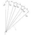
- FIG. 2 is a diagram schematically showing a transmission concept.
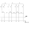
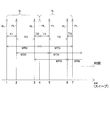
- FIG. 3 is a diagram showing transmission timings and transmission intervals of a plurality of pulse signals PL that are periodically and repeatedly transmitted.
- the radar device includes an antenna 1, a circulator 2, a transmitter 3, a receiver 4, and a processor 6 that controls the transmitter 3 and processes signals from the receiver 4. ..
- the processor 6 serves as a radar control device.
- the processor 6 realizes a transmission pattern setting unit 60, an MTI cycle determining unit 61, an interference removal processing unit 62, and an MTI processing unit 63.
- the MTI processing unit 63 has a Doppler velocity calculation unit 64 and a land removal unit 65.
- the radar device has a transmission unit 3 and a transmission pattern setting unit 60.
- the transmitter 3 generates the pulse signal PL shown in FIGS. 2 and 3 and sequentially outputs the pulse signal PL to the circulator 2. As a result, the pulse signal PL is repeatedly transmitted via the antenna 1.
- the transmission pattern setting unit 60 controls the transmission unit 30 by giving the transmission pattern to the transmission unit 30.
- the transmission pattern represents the transmission timing of the plurality of pulse signals PL, as shown in FIGS. 2 and 3.
- the transmission timing includes at least two or more different transmission intervals Ti1 and Ti2 and is periodically repeated. As shown in FIG. 3, at least two or more different transmission intervals Ti1 and Ti2 are continuous in time series. In the example of FIGS.
- the first transmission interval Ti1 between the pulse signal PL of the first sweep sw1 and the pulse signal PL of the second sweep sw2 is 1/2000 seconds (2000 Hz), and the pulse of the second sweep sw2.
- the second transmission interval Ti2 between the signal PL and the pulse signal PL of the third sweep sw3 is 1/1600 seconds (1600 Hz).
- the first transmission interval Ti1 and the second transmission interval Ti2 are repeated, and the third sweep sw3 (pulse signal PL), the fourth sweep sw4 (pulse signal PL), the fifth sweep sw5 (pulse signal PL), the sixth sweep.
- the sw6 (pulse signal PL) and the seventh sweep sw7 (pulse signal PL) are sequentially transmitted.
- the transmission pulse group G having the first transmission interval Ti1 and the second transmission interval Ti2 following the first transmission interval Ti1 is repeatedly transmitted.
- the length (frequency) of the transmission intervals Ti1 and Ti2 is an example for convenience of description, and is not limited to this.
- the circulator 2 transmits the pulse signal PL output from the transmitter 30 to the antenna 1.
- the antenna 1 radiates a plurality of pulse signals PL (first to sixth sweeps sw1 to sw6) input via the circulator 2 to the outside with a predetermined directivity. With this configuration, as shown in FIG. 2, a plurality of pulse signals PL are emitted while sequentially changing the direction.
- the antenna 1 receives radio waves coming from the outside and outputs the received signal to the circulator 2.
- the received signal includes the reflected signal of the pulse signal PL radiated from the antenna 1.
- the circulator 2 transmits the reception signal propagated from the antenna 1 to the reception unit 4.
- the receiver 4 samples the input signal and inputs the digitized signal to the interference cancellation processor 62.
- the interference removal processing unit 62 executes an interference removal process that removes interference and influence such as multiple reflections caused by clutter and the like with transmission signals of other radar devices mixed in the received signal.
- the interference removal process is widely known, and therefore a detailed description thereof will be omitted.
- the data processed by the interference removal processing unit 62 is input to the MTI processing unit 63.
- the MTI cycle determination unit 61 determines the MTI cycle based on the transmission pattern set by the transmission pattern setting unit 60.
- the MTI cycle is used by the MTI processing unit 63.
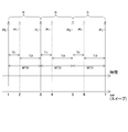
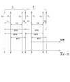
- the MTI cycle determination unit 61 determines the MTI cycles MTI1 and MTI2, which are times obtained by adding at least two or more different transmission intervals Ti1 and Ti2.
- the MTI cycle determining unit 61 determines at least one of the first MTI cycle MTI1 and the second MTI cycle MTI2.
- the first MTI cycle MTI1 has the first transmission interval Ti1 as a head, and the first transmission interval Ti1 and the second transmission interval Ti2 are sequentially arranged in time series.
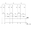
- the second transmission interval Ti2 is at the head, and the respective transmission intervals are consecutive in time series in the order of the second transmission interval Ti2 and the first transmission interval Ti1.
- the MTI processing unit 63 executes MTI processing based on the MTI cycle determined by the MTI cycle determining unit 61 and the received signal.
- the MTI process is calculation of Doppler velocity and removal of ground clutter based on Doppler velocity.
- the MTI processing unit 63 has a Doppler velocity calculation unit 64 and a land removal unit 65.
- the Doppler velocity calculation unit 64 uses the received signal of the pulse signal PL and the MTI cycle transmitted based on the transmission pattern, and among the received signals, the received signal corresponding to the first pulse signal PL in the MTI cycle and the last pulse signal.
- the Doppler velocity is calculated from the amount of phase change with the received signal corresponding to.
- the combination of the first pulse signal and the last pulse signal in the first MTI cycle MTI1 is (first sweep sw1, third sweep sw3), third sweep sw3, fifth sweep sw5), (5th sweep sw5, 7th sweep sw7). Therefore, the Doppler velocity is calculated from the amount of phase change between the received signals of the first sweep sw1 and the third sweep sw3. The Doppler velocity is calculated from the amount of phase change between the reception signals of the third sweep sw3 and the fifth sweep sw5. The Doppler velocity is calculated from the amount of phase change between the reception signals of the fifth sweep sw5 and the seventh sweep sw7.
- the Doppler velocity calculation timing is based on the reception time points of the reflected signals of the third sweep sw3, the fifth sweep sw5, and the seventh sweep sw7.
- the sweep reception signal may be stored in a buffer and processed in sequence.
- the combination of the first pulse signal and the last pulse signal in the second MTI cycle MTI2 is (second sweep sw2, fourth sweep sw4), (fourth sweep sw4, sixth sweep sw6).
- the Doppler velocity is calculated from the amount of phase change between the received signals of the second sweep sw2 and the fourth sweep sw4.
- the Doppler velocity is calculated from the amount of phase change between the received signals of the fourth sweep sw4 and the sixth sweep sw6.
- the calculation timing of the Doppler velocity is based on the reception time point of the reflected signals of the second sweep sw2, the fourth sweep sw4, and the sixth sweep sw6.
- the land removing unit 65 removes a signal that becomes a land based on the Doppler speed calculated by the Doppler speed calculating unit 64. If the Doppler velocity is zero, almost zero, or less than a predetermined threshold, it is considered as land and removed. Almost zero means a value that can be treated as zero, although it is not completely zero due to fluctuations in observation data.
- the land removing unit 65 may remove the phase change amount as zero, substantially zero, or less than or equal to a predetermined threshold value, and remove the land, which is synonymous with the processing.
- the MTI processing unit 63 may execute only the MTI processing using the first MTI cycle MTI1, may only execute the MTI processing using the second MTI cycle MTI2, or may use the first MTI cycle MTI1. Both the processing and the MTI processing using the second MTI cycle MTI2 may be executed and the respective results may be combined.
- each MTI cycle (first MTI cycle MTI1, second MTI cycle MTI2) becomes a fixed time width. If the time width of the MTI cycle is different, a computer resource is required for each time width, but since the time width of the MTI cycle is constant, one computer resource corresponds to both the first MTI cycle MTI1 and the second MTI cycle MTI2. It will be possible.
- the control of the dual polarization radar using the horizontal polarization (H wave) and the vertical polarization (V wave) is described, but the present invention is not limited to this.
- a polarized wave radar may be used.
- PPI scan orthogonal scanning
- RHI scanning orthogonal elevation angle operation
- the processor 6 has a post-processing unit 66 that processes the data processed by the MTI processing unit 63.
- the post-processing unit 66 removes the vessel from the received signal, removes the vessel from the received signal phase information, calculates the Doppler velocity from the received signal phase information, multi-parameter [ ⁇ Dp (polarization phase difference), kdp (phase Change rate)], a process of calculating precipitation intensity from the intensity information of the received signal, a multi-parameter [Zh (intensity of H wave), Zv (intensity of V wave), Zdr (flat) from intensity information of the received signal. Degree)], and/or the like.
- the above embodiment is an example in which the transmission pattern includes two different first transmission intervals Ti1 and second transmission intervals Ti2, but is not limited to this.
- the present disclosure is also applicable when the transmission pattern has three or more different transmission intervals Ti1, Ti2, and Ti3.
- FIG. 6 is an example in which three different transmission intervals (first transmission interval Ti1, second transmission interval Ti2, third transmission interval Ti3) are periodically repeated.
- the MTI cycle determination unit 61 can determine three MTI cycles (MTI3, MTI4, MTI5). In the MTI cycle MTI3, the first transmission interval Ti1 is the head, and the second transmission interval Ti2 and the third transmission interval Ti3 are consecutive in time series.
- the MTI cycle MTI4 starts with the second transmission interval Ti2, and the third transmission interval Ti3 and the first transmission interval Ti1 are successively arranged in time series.
- the MTI cycle MTI5 starts with the third transmission interval Ti3, and the first transmission interval Ti1 and the second transmission interval Ti2 are consecutive in time series.
- the MTI cycle determining unit 61 may determine at least one cycle of these MTI cycles (MTI3, MTI4, MTI5). If a plurality of MTI cycles with different time widths are not used, as shown in FIG. 7, either MTI cycle MTI6 or MTI cycle MTI7 can be determined in addition to MTI cycle MTI3.
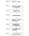
- FIG. 8 shows a flow executed by the radar device.
- the transmission pattern setting unit 60 sets the transmission pattern.
- the transmitter 3 transmits the pulse signal PL based on the transmission pattern.
- the receiving unit 4 receives the received signal.
- the interference removal processing unit 62 executes the interference removal processing.
- the MTI cycle determination unit 61 determines the MTI cycle based on the transmission pattern. Note that the determination of the MTI cycle may be executed at any point as long as it is after step ST100 and before step ST105.
- the Doppler velocity calculation unit 64 calculates the Doppler velocity using the MTI cycle.
- the land removing unit 65 removes the land based on the Doppler velocity.
- the post-processing unit 66 executes a predetermined post-processing.
- the radar control device of the present embodiment is A transmission pattern setting unit 60 that sets a transmission pattern that is a transmission timing of a plurality of pulse signals PL that includes at least two or more different transmission intervals (Ti1 to 3) and that is periodically repeated; At least two or more different transmission intervals (Ti1 to 3) are continuous in time series, and MTI that determines the MTI cycle (MTI1 to 7) that is the time obtained by adding at least two or more different transmission intervals (Ti1 to 3).
- a cycle determining unit 61 Using the received signal of the pulse signal PL and the MTI cycle (MTI1 to 7) transmitted based on the transmission pattern, the received signal corresponding to the first pulse signal in the MTI cycle (MTI1 to 7) and the last of the received signals A Doppler velocity calculation unit 64 that calculates the Doppler velocity from the amount of phase change with the received signal corresponding to the pulse signal of A land removal unit 65 that removes a land signal based on the Doppler speed, Equipped with.
- the radar control method of this embodiment is Setting a transmission pattern that is a transmission timing of a plurality of pulse signals PL that includes at least two or more different transmission intervals (Ti1 to 3) and is periodically repeated; At least two or more different transmission intervals (Ti1 to 3) are continuous in time series, and determine an MTI cycle (MTI1 to 7) which is a time obtained by adding at least two or more different transmission intervals (Ti1 to 3).
- the received signal corresponding to the first pulse signal in the MTI cycle (MTI1 to 7) and the last of the received signals Calculating the Doppler velocity from the amount of phase change with the received signal corresponding to the pulse signal of Removing signals that are land based on Doppler velocity, including.
- the MTI cycle has a fixed time width, MTI processing can be shared by one processing block, and computer resources can be reduced. Even so, since the MTI cycle is periodic, it is possible to obtain the calculation timing periodically, which may improve the ground clutter removal accuracy.
- the land removing unit 65 removes a signal having a Doppler velocity of zero, substantially zero, or a predetermined threshold value or less. This is a preferred embodiment.
- a transmission pulse group G having a first transmission interval Ti1 and a second transmission interval Ti2 following the first transmission interval Ti1 is repeatedly transmitted,
- the MTI cycle determining unit 61 determines at least one MTI cycle of the first MTI cycle MTI1 having the first transmission interval Ti1 as the head and the second MTI cycle MTI2 having the second transmission interval Ti2 as the head,
- the MTI processing including the calculation of the Doppler velocity and the removal of the land signal is preferably executed using the first MTI cycle MTI1 or the second MTI cycle MTI2.
- the received signals corresponding to the pulse signals having the same transmission interval are compared with each other in the MTI cycle including the transmission interval, so that the land removal accuracy can be improved.
- the MTI cycle determining unit 61 determines both the first MTI cycle MTI1 and the second MTI cycle MTI2, and uses the MTI processing using the first MTI cycle MTI1 and the second MTI cycle MTI2. Both the MTI process and the MTI process are executed.
- the first MTI cycle MTI1 and the second MTI cycle MTI2 overlap each other, so that the sampling frequency becomes high and the ground clutter removal performance can be improved.
- the MTI cycle determining unit 61 adds at least two or more different transmission intervals (Ti1 to 2, Ti1 to 3). It is preferable to determine the time as the MTI period.
- the first and last pulse signals in the MTI cycle become pulse signals for the transmission intervals having the same time width, and the reception signals corresponding to the pulse signals having the same transmission interval are compared with each other. Therefore, it becomes possible to improve the precision of land removal. Nevertheless, since the time widths of all MTI cycles are the same, a single processing block can be shared and the computational resources can be reduced.
- the program according to the present embodiment is a program that causes one or more processors to execute the above method.
- All processes described herein may be embodied by software code modules executed by a computing system including one or more computers or processors and may be fully automated.
- the code modules may be stored on any type of non-transitory computer readable medium or other computer storage device. Some or all of the methods may be embodied in dedicated computer hardware.
- any particular action, event, or function of any of the algorithms described herein can be performed in a different sequence, and can be added, merged, or omitted altogether. (For example, not all described acts or events are required to execute an algorithm). Further, in certain embodiments, the actions or events may be executed in parallel rather than serially, eg, via multithreaded processing, interrupt processing, or through multiple processors or processor cores, or on other parallel architectures. You can Moreover, different tasks or processes may be performed by different machines and/or computing systems that may work together.
- the processor may be a microprocessor, but in the alternative, the processor may be a controller, microcontroller, or state machine, combinations thereof, or the like.
- the processor can include electrical circuitry configured to process computer-executable instructions.
- the processor comprises an application specific integrated circuit (ASIC), field programmable gate array (FPGA), or other programmable device that performs logical operations without processing computer-executable instructions.
- ASIC application specific integrated circuit
- FPGA field programmable gate array
- a processor may also be a combination of computing devices, such as a combination of digital signal processors (digital signal processors) and microprocessors, multiple microprocessors, one or more microprocessors in combination with DSP cores, or any other thereof. It can be implemented as such a configuration. Although described primarily herein in the context of digital technology, a processor may also include primarily analog components. For example, some or all of the signal processing algorithms described herein may be implemented by analog circuits or mixed analog and digital circuits.
- a computing environment includes any type of computer system including, but not limited to, a microprocessor, mainframe computer, digital signal processor, portable computing device, device controller, or computing engine-based computer system within an apparatus. be able to.
- conditional languages such as “capable”, “capable”, “possible” or “possible” refer to particular features, elements and/or steps that a particular embodiment includes. Embodiments are understood in the sense of the context commonly used to convey what is not included. Thus, such a conditional language is generally any method in which features, elements and/or steps are required for one or more embodiments, or one or more embodiments It is not meant to necessarily include the logic to determine whether an element and/or step is included in or executed by any particular embodiment.
- a disjunctive language such as the phrase "at least one of X, Y, and Z" is an item, term, etc., any of X, Y, Z, or any combination thereof, unless otherwise specified. Understood in a commonly used context to indicate that (eg, X, Y, Z). Accordingly, such disjunctive languages generally require each of at least one of X, at least one of Y, or at least one of Z for which a particular embodiment is present. Does not mean.
- Numerals such as “one” should generally be construed to include one or more described items unless specifically stated. Thus, phrases such as “one device configured to” are intended to include one or more of the listed devices. Such one or more enumerated devices may also be collectively configured to perform the recited citations. For example, "a processor configured to perform A, B, and C below” refers to a first processor configured to perform A and a second processor configured to perform B and C. And a processor. Additionally, even if a specific number listing of the introduced examples is explicitly recited, one of ordinary skill in the art will appreciate that such listings typically include at least the recited number (e.g. The mere enumeration of "with two enumerations” without “is usually meant to mean at least two enumerations, or more than one enumeration.”
- the term “horizontal” as used herein, regardless of its orientation, is a plane parallel to the plane or surface of the floor of the area in which the described system is used, or description. Is defined as the plane in which the method is performed.
- the term “floor” can be replaced with the terms “ground” or “water surface”.
- the term “vertical/vertical” refers to the direction vertical/vertical to the defined horizontal line. Terms such as “upper”, “lower”, “lower”, “upper”, “side”, “higher”, “lower”, “upward”, “above”, and “below” are defined with respect to the horizontal plane. ing.
- connection/coupling includes direct connection and/or connection having an intermediate structure between the two described components.
- the numbers preceded by terms such as “approximately”, “about”, and “substantially” include the recited numbers, and unless otherwise indicated. Represents an amount near the stated amount that performs a desired function or achieves a desired result. For example, “approximately”, “about” and “substantially” refer to values that are less than 10% of the stated numerical value, unless expressly specified otherwise. As used herein, features of the embodiments in which the terms such as “approximately”, “about”, and “substantially” are previously disclosed perform the desired function as well. Or represents a feature with some variability in achieving that desired result.
Landscapes
- Engineering & Computer Science (AREA)
- Radar, Positioning & Navigation (AREA)
- Remote Sensing (AREA)
- Computer Networks & Wireless Communication (AREA)
- Physics & Mathematics (AREA)
- General Physics & Mathematics (AREA)
- Radar Systems Or Details Thereof (AREA)
Abstract
【課題】グランドクラッタの除去精度の向上と、必要な計算機資源を少なくすることとを実現可能な、レーダ制御装置を提供する。 【解決手段】レーダ制御装置は、少なくとも2つ以上の異なる送信間隔(Ti1~3)を含み、周期的に繰り返される、複数のパルス信号PLの送信タイミングである送信パターンを設定する送信パターン設定部60と、時系列で連続する少なくとも2つ以上の異なる送信間隔を足した時間であるMTI周期(MTI1~7)を決定するMTI周期決定部61と、送信パターンに基づき送信されたパルス信号PLの受信信号とMTI周期(MTI1~7)とを用い、受信信号のうち、前記MTI周期(MTI1~7)における最初のパルス信号に対応する受信信号と最後のパルス信号に対応する受信信号との位相変化量からドップラ速度を算出するドップラ速度算出部64と、ドップラ速度に基づき陸地となる信号を除去する陸地除去部65と、を有する。
Description
本開示は、レーダ制御装置、レーダ制御方法及びプログラムに関する。
気象レーダは、所定の送信間隔を有するパルス信号をアンテナを介して放射する。放射されたパルス信号の一部は、気象目標から反射され、一部は地面や山等の気象目標以外のものから反射される。反射された信号はアンテナで受信され、受信処理を行うプロセッサに入力される。プロセッサにおいて、不要な信号である山や地面等からの反射信号(陸地エコー、グランドクラッタ)を除去し、降水エコー等の気象目標のみを抽出することが要求される。
特許文献1には、送信間隔が異なる2種類のパルス信号を送信し、受信信号に対してグランドクラッタを除去することについての記載がある。送信間隔が異なる二種類のパルス信号を送信することは2重PRF(Pulse Repetition Frequency)であると説明されている。
グランドクラッタの除去法として、MTI(Moving Target Indicator)法が知られている。一般的なMTI処理は、入力信号と、入力信号の1パルス前の信号との、信号強度と位相差からドップラ速度を算出し、ドップラ速度がゼロ又は略ゼロとなる領域を陸地と判定して除去する処理である。なお、特許文献2にMTI処理についての開示がある。
しかしながら、一般的なMTI処理を2重PRFに適用した場合には、次の問題が生じる。2重PRFにおいて第1パルスの送信から第1送信間隔経過後に第2パルスが送信され、第2パルスの送信から第2送信間隔経過後に第1パルスが送信される。第1パルスと第2パルスとが繰り返し送信される。2重PRFに一般的なMTI処理を適用したとすれば、送信間隔が異なる第1パルスと第2パルスとに対応するそれぞれの受信信号間の位相差に基づきグランドクラッタを除去するため、送信間隔が異なるパルスの受信信号同士を、一方の送信間隔と等しいMTI周期で比較することになり、クラッタ除去の精度が悪化する。また、送信間隔が2つ存在するので、第1送信間隔用のMTI処理ブロックと、第2送信間隔用のMTI処理ブロックとの2つの処理ブロックが必要となり、必要な計算機資源が冗長化してしまう。
本開示の目的は、グランドクラッタの除去精度の向上と、必要な計算機資源を少なくすることとを実現可能な、レーダ制御装置、レーダ制御方法及びプログラムを提供することである。
本開示のレーダ制御装置は、
少なくとも2つ以上の異なる送信間隔を含み、周期的に繰り返される、複数のパルス信号の送信タイミングである送信パターンを設定する送信パターン設定部と、
前記少なくとも2つ以上の異なる送信間隔は時系列で連続し、当該少なくとも2つ以上の異なる送信間隔を足した時間であるMTI周期を決定するMTI周期決定部と、
前記送信パターンに基づき送信されたパルス信号の受信信号と前記MTI周期とを用い、前記受信信号のうち、前記MTI周期における最初のパルス信号に対応する受信信号と最後のパルス信号に対応する受信信号との位相変化量からドップラ速度を算出するドップラ速度算出部と、
前記ドップラ速度に基づき陸地となる信号を除去する陸地除去部と、
を備える。
少なくとも2つ以上の異なる送信間隔を含み、周期的に繰り返される、複数のパルス信号の送信タイミングである送信パターンを設定する送信パターン設定部と、
前記少なくとも2つ以上の異なる送信間隔は時系列で連続し、当該少なくとも2つ以上の異なる送信間隔を足した時間であるMTI周期を決定するMTI周期決定部と、
前記送信パターンに基づき送信されたパルス信号の受信信号と前記MTI周期とを用い、前記受信信号のうち、前記MTI周期における最初のパルス信号に対応する受信信号と最後のパルス信号に対応する受信信号との位相変化量からドップラ速度を算出するドップラ速度算出部と、
前記ドップラ速度に基づき陸地となる信号を除去する陸地除去部と、
を備える。
このようにすれば、MTI周期が一定時間幅となるので、MTI処理を一つの処理ブロックで共用でき、計算機資源を削減可能となる。それでいて、MTI周期が周期的であるので、計算タイミングを周期的に得ることが可能となり、グランドクラッタの除去精度を向上できる場合がある。
以下、本開示の一実施形態を、図面を参照して説明する。
図1は、本実施形態のレーダ装置及びレーダ装置を制御するレーダ制御装置の構成を示す図である。図2は、送信概念を模式的に示した図である。図3は、周期的に繰り返し送信される複数のパルス信号PLの送信タイミング及び送信間隔を示す図である。
図1に示すように、レーダ装置は、アンテナ1と、サーキュレータ2と、送信部3と、受信部4と、送信部3の制御及び受信部4からの信号を処理するプロセッサ6と、を有する。プロセッサ6がレーダ制御装置となる。プロセッサ6は、送信パターン設定部60、MTI周期決定部61、干渉除去処理部62、MTI処理部63を実現する。MTI処理部63は、ドップラ速度算出部64及び陸地除去部65を有する。
レーダ装置は、送信部3及び送信パターン設定部60を有する。送信部3は、図2及び図3に示すパルス信号PLを生成し、順次、サーキュレータ2へ出力する。これにより、アンテナ1を介してパルス信号PLが繰り返し送信される。送信パターン設定部60は、送信パターンを送信部30に与えることにより、送信部30を制御する。送信パターンは、図2及び図3に示すように、複数のパルス信号PLの送信タイミングを表す。送信タイミングは、少なくとも2つ以上の異なる送信間隔Ti1、Ti2を含み、周期的に繰り返される。図3に示すように、少なくとも2つ以上の異なる送信間隔Ti1、Ti2が時系列で連続している。図2及び図3の例では、第1スイープsw1のパルス信号PLと第2スイープsw2のパルス信号PLとの第1送信間隔Ti1が1/2000秒(2000Hz)であり、第2スイープsw2のパルス信号PLと第3スイープsw3のパルス信号PLとの第2送信間隔Ti2が1/1600秒(1600Hz)である。以後、第1送信間隔Ti1及び第2送信間隔Ti2が繰り返され、第3スイープsw3(パルス信号PL)、第4スイープsw4(パルス信号PL)、第5スイープsw5(パルス信号PL)、第6スイープsw6(パルス信号PL)、第7スイープsw7(パルス信号PL)が順次送信される。これにより、図3に示すように、第1送信間隔Ti1と、第1送信間隔Ti1に続く第2送信間隔Ti2とを有する送信パルス群Gが繰り返し送信されることになる。
なお、送信間隔Ti1、Ti2の長さ(周波数)は説明の便宜のための例示であり、これに限定されない。
サーキュレータ2は、送信部30から出力されたパルス信号PLをアンテナ1に伝送する。アンテナ1は、サーキュレータ2を介して入力された複数のパルス信号PL(第1~第6のスイープsw1~6)を所定の指向性で外部へ放射する。この構成により、図2に示すように複数のパルス信号PLが、方位を順次変えながら放射される。
アンテナ1は、外部から到来した電波を受信して受信信号をサーキュレータ2へ出力する。この受信信号には、アンテナ1から放射したパルス信号PLの反射信号が含まれている。サーキュレータ2は、アンテナ1から伝搬された受信信号を受信部4へ伝送する。受信部4は、入力された信号をサンプリングし、デジタル化した信号を干渉除去処理部62へ入力する。
干渉除去処理部62は、受信信号に混入する他のレーダ装置の送信信号と、クラッタ等による多重反射等の干渉・影響を除去する干渉除去処理を実行する。干渉除去処理は、広く知られているので詳細な説明は省略する。干渉除去処理部62で処理されたデータは、MTI処理部63に入力される。
MTI周期決定部61は、送信パターン設定部60が設定した送信パターンに基づいてMTI周期を決定する。MTI周期は、MTI処理部63で使用される。MTI周期決定部61は、図4又は図5に示すように、少なくとも2つ以上の異なる送信間隔Ti1、Ti2を足した時間であるMTI周期MTI1、MTI2を決定する。本実施形態では、MTI周期決定部61は、第1MTI周期MTI1、又は、第2MTI周期MTI2の少なくともいずれかのMTI周期を決定する。第1MTI周期MTI1は、図4に示すように、第1送信間隔Ti1を先頭とし、第1送信間隔Ti1、第2送信間隔Ti2の順に各送信間隔が時系列に連続している。第2MTI周期MTI2は、図5に示すように、第2送信間隔Ti2を先頭とし、第2送信間隔Ti2、第1送信間隔Ti1の順に各送信間隔が時系列に連続している。第1MTI周期MTI1及び第2MTI周期MTI2は、1/2000秒+1/1600秒=約1/888秒(約888Hz)であり、いずれも時間長さが同じである。時間長さを周波数で表現すれば周波数が同じである。
MTI処理部63は、MTI周期決定部61が決定したMTI周期と受信信号に基づきMTI処理を実行する。MTI処理は、ドップラ速度の算出及びドップラ速度に基づくグランドクラッタの除去である。MTI処理部63は、図1に示すように、ドップラ速度算出部64及び陸地除去部65を有する。ドップラ速度算出部64は、送信パターンに基づき送信されたパルス信号PLの受信信号とMTI周期とを用い、受信信号のうち、MTI周期における最初のパルス信号PLに対応する受信信号と最後のパルス信号に対応する受信信号との位相変化量からドップラ速度を算出する。
図4の例で説明すれば、第1MTI周期MTI1における最初のパルス信号と最後のパルス信号の組み合わせは、(第1スイープsw1、第3スイープsw3)、第3スイープsw3、第5スイープsw5)、(第5スイープsw5、第7スイープsw7)である。よって、第1スイープsw1及び第3スイープsw3の受信信号間の位相変化量からドップラ速度が算出される。第3スイープsw3及び第5スイープsw5の受信信号間の位相変化量からドップラ速度が算出される。第5スイープsw5及び第7スイープsw7の受信信号間の位相変化量からドップラ速度が算出される。ドップラ速度の算出タイミングは、第3スイープsw3、第5スイープsw5及び第7スイープsw7の反射信号の受信時点に基づく。なお、スイープの受信信号をバッファに貯めておいて、順に信号処理してもよい。
図5の例で説明すれば、第2MTI周期MTI2における最初のパルス信号と最後のパルス信号の組み合わせは、(第2スイープsw2、第4スイープsw4)、(第4スイープsw4、第6スイープsw6)である。よって、第2スイープsw2及び第4スイープsw4の受信信号間の位相変化量からドップラ速度が算出される。第4スイープsw4及び第6スイープsw6の受信信号間の位相変化量からドップラ速度が算出される。ドップラ速度の算出タイミングは、第2スイープsw2、第4スイープsw4及び第6スイープsw6の反射信号の受信時点に基づく。
陸地除去部65は、ドップラ速度算出部64が算出したドップラ速度に基づき陸地となる信号を除去する。ドップラ速度がゼロ、略ゼロ又は所定閾値以下であれば、陸地であるとして除去する。略ゼロは、観測データのゆらぎによって完全なゼロではないが、ゼロと扱ってよい値を意味する。なお、陸地除去部65が、上記位相変化量がゼロ、略ゼロ又は所定閾値以下であれば、陸地であるとして除去するようにしてもよく、処理としては同義である。
MTI処理部63は、第1MTI周期MTI1を用いたMTI処理のみを実行してもよいし、第2MTI周期MTI2を用いたMTI処理のみを実行してもよいし、第1MTI周期MTI1を用いたMTI処理と第2MTI周期MTI2を用いたMTI処理との双方を実行して各結果を結合してもよい。
このようにすれば、各々のMTI周期(第1MTI周期MTI1、第2MTI周期MTI2)が一定時間幅となる。MTI周期の時間幅が異なれば、時間幅毎に計算機資源が必要となるが、MTI周期の時間幅が一定であるので、一つの計算機資源で第1MTI周期MTI1、第2MTI周期MTI2の双方に対応可能となる。
なお、本実施形態では、横方向の偏波(H波)及び縦方向の偏波(V波)を用いた二重偏波レーダの制御について説明しているが、これに限定されず、一偏波のレーダを用いてもよい。また、図2は、PPIスキャン(アンテナ水平走査)について説明したが、これに限定されず、RHIスキャン(アンテナ仰角操作)でも本開示を適用可能である。
プロセッサ6は、MTI処理部63の処理後のデータを処理する後処理部66を有する。後処理部66は、受信信号から船舶を除去する船舶除去処理、受信信号の位相情報からドップラ速度を算出する処理、受信信号の位相情報からマルチパラメータ[φDp(偏波間位相差)、kdp(位相変化率)]を算出する処理、受信信号の強度情報から降水強度を算出する処理、受信信号の強度情報からマルチパラメータ[Zh(H波の強度)、Zv(V波の強度)、Zdr(偏平度)]を算出する処理、等の少なくともいずれかが挙げられる。
[変形例]
上記実施形態では、送信パターンが2つの異なる第1送信間隔Ti1及び第2送信間隔Ti2を含む例であるが、これに限定されない。送信パターンが3つ以上の異なる送信間隔Ti1、Ti2、Ti3を有する場合も本開示が適用可能である。図6は、3つの異なる送信間隔(第1送信間隔Ti1、第2送信間隔Ti2、第3送信間隔Ti3)が周期的に繰り返される例である。この場合、MTI周期決定部61が決定可能なMTI周期は3つ(MTI3、MTI4、MTI5)挙げられる。MTI周期MTI3は、第1送信間隔Ti1を先頭とし、第2送信間隔Ti2及び第3送信間隔Ti3が順に時系列に連続する。MTI周期MTI4は、第2送信間隔Ti2を先頭とし、第3送信間隔Ti3及び第1送信間隔Ti1が順に時系列に連続する。MTI周期MTI5は、第3送信間隔Ti3を先頭とし、第1送信間隔Ti1及び第2送信間隔Ti2が順に時系列に連続する。MTI周期決定部61は、これらのMTI周期(MTI3、MTI4、MTI5)のうち少なくとも1つの周期を決定すればよい。なお、時間幅の異なる複数のMTI周期を用いないのであれば、図7に示すように、MTI周期MTI3の他、MTI周期MTI6、又はMTI周期MTI7のいずれかを決定可能である。
上記実施形態では、送信パターンが2つの異なる第1送信間隔Ti1及び第2送信間隔Ti2を含む例であるが、これに限定されない。送信パターンが3つ以上の異なる送信間隔Ti1、Ti2、Ti3を有する場合も本開示が適用可能である。図6は、3つの異なる送信間隔(第1送信間隔Ti1、第2送信間隔Ti2、第3送信間隔Ti3)が周期的に繰り返される例である。この場合、MTI周期決定部61が決定可能なMTI周期は3つ(MTI3、MTI4、MTI5)挙げられる。MTI周期MTI3は、第1送信間隔Ti1を先頭とし、第2送信間隔Ti2及び第3送信間隔Ti3が順に時系列に連続する。MTI周期MTI4は、第2送信間隔Ti2を先頭とし、第3送信間隔Ti3及び第1送信間隔Ti1が順に時系列に連続する。MTI周期MTI5は、第3送信間隔Ti3を先頭とし、第1送信間隔Ti1及び第2送信間隔Ti2が順に時系列に連続する。MTI周期決定部61は、これらのMTI周期(MTI3、MTI4、MTI5)のうち少なくとも1つの周期を決定すればよい。なお、時間幅の異なる複数のMTI周期を用いないのであれば、図7に示すように、MTI周期MTI3の他、MTI周期MTI6、又はMTI周期MTI7のいずれかを決定可能である。
[レーダ制御方法]
図8は、上記レーダ装置が実行するフローを示す。ステップST100において、送信パターン設定部60が送信パターンを設定する。ステップST101において、送信部3が送信パターンに基づきパルス信号PLを送信する。ステップST102において、受信部4が受信信号を受信する。次のステップST103において、干渉除去処理部62が干渉除去処理を実行する。ステップST104において、MTI周期決定部61が送信パターンに基づきMTI周期を決定する。なお、MTI周期の決定は、ステップST100以降且つST105より前であれば、どの時点で実行してもよい。次のステップST105において、ドップラ速度算出部64がMTI周期を用いてドップラ速度を算出する。次のステップST106において、陸地除去部65がドップラ速度に基づき陸地を除去する。次のステップST107において、後処理部66が所定の後処理を実行する。
図8は、上記レーダ装置が実行するフローを示す。ステップST100において、送信パターン設定部60が送信パターンを設定する。ステップST101において、送信部3が送信パターンに基づきパルス信号PLを送信する。ステップST102において、受信部4が受信信号を受信する。次のステップST103において、干渉除去処理部62が干渉除去処理を実行する。ステップST104において、MTI周期決定部61が送信パターンに基づきMTI周期を決定する。なお、MTI周期の決定は、ステップST100以降且つST105より前であれば、どの時点で実行してもよい。次のステップST105において、ドップラ速度算出部64がMTI周期を用いてドップラ速度を算出する。次のステップST106において、陸地除去部65がドップラ速度に基づき陸地を除去する。次のステップST107において、後処理部66が所定の後処理を実行する。
以上のように、本実施形態のレーダ制御装置は、
少なくとも2つ以上の異なる送信間隔(Ti1~3)を含み、周期的に繰り返される、複数のパルス信号PLの送信タイミングである送信パターンを設定する送信パターン設定部60と、
少なくとも2つ以上の異なる送信間隔(Ti1~3)は時系列で連続し、少なくとも2つ以上の異なる送信間隔(Ti1~3)を足した時間であるMTI周期(MTI1~7)を決定するMTI周期決定部61と、
送信パターンに基づき送信されたパルス信号PLの受信信号とMTI周期(MTI1~7)とを用い、受信信号のうち、前記MTI周期(MTI1~7)における最初のパルス信号に対応する受信信号と最後のパルス信号に対応する受信信号との位相変化量からドップラ速度を算出するドップラ速度算出部64と、
ドップラ速度に基づき陸地となる信号を除去する陸地除去部65と、
を備える。
少なくとも2つ以上の異なる送信間隔(Ti1~3)を含み、周期的に繰り返される、複数のパルス信号PLの送信タイミングである送信パターンを設定する送信パターン設定部60と、
少なくとも2つ以上の異なる送信間隔(Ti1~3)は時系列で連続し、少なくとも2つ以上の異なる送信間隔(Ti1~3)を足した時間であるMTI周期(MTI1~7)を決定するMTI周期決定部61と、
送信パターンに基づき送信されたパルス信号PLの受信信号とMTI周期(MTI1~7)とを用い、受信信号のうち、前記MTI周期(MTI1~7)における最初のパルス信号に対応する受信信号と最後のパルス信号に対応する受信信号との位相変化量からドップラ速度を算出するドップラ速度算出部64と、
ドップラ速度に基づき陸地となる信号を除去する陸地除去部65と、
を備える。
本実施形態のレーダ制御方法は、
少なくとも2つ以上の異なる送信間隔(Ti1~3)を含み、周期的に繰り返される、複数のパルス信号PLの送信タイミングである送信パターンを設定することと、
少なくとも2つ以上の異なる送信間隔(Ti1~3)は時系列で連続し、少なくとも2つ以上の異なる送信間隔(Ti1~3)を足した時間であるMTI周期(MTI1~7)を決定することと、
送信パターンに基づき送信されたパルス信号PLの受信信号とMTI周期(MTI1~7)とを用い、受信信号のうち、前記MTI周期(MTI1~7)における最初のパルス信号に対応する受信信号と最後のパルス信号に対応する受信信号との位相変化量からドップラ速度を算出することと、
ドップラ速度に基づき陸地となる信号を除去することと、
を含む。
少なくとも2つ以上の異なる送信間隔(Ti1~3)を含み、周期的に繰り返される、複数のパルス信号PLの送信タイミングである送信パターンを設定することと、
少なくとも2つ以上の異なる送信間隔(Ti1~3)は時系列で連続し、少なくとも2つ以上の異なる送信間隔(Ti1~3)を足した時間であるMTI周期(MTI1~7)を決定することと、
送信パターンに基づき送信されたパルス信号PLの受信信号とMTI周期(MTI1~7)とを用い、受信信号のうち、前記MTI周期(MTI1~7)における最初のパルス信号に対応する受信信号と最後のパルス信号に対応する受信信号との位相変化量からドップラ速度を算出することと、
ドップラ速度に基づき陸地となる信号を除去することと、
を含む。
このようにすれば、MTI周期が一定時間幅となるので、MTI処理を一つの処理ブロックで共用でき、計算機資源を削減可能となる。それでいて、MTI周期が周期的であるので、計算タイミングを周期的に得ることが可能となり、グランドクラッタの除去精度を向上できる場合がある。
本実施形態のように、陸地除去部65は、ドップラ速度がゼロ、略ゼロ又は所定の閾値以下の信号を除去することが好ましい。好ましい実施例である。
図4又は図5に示すように、第1送信間隔Ti1と、第1送信間隔Ti1に続く第2送信間隔Ti2とを有する送信パルス群Gが繰り返し送信され、
MTI周期決定部61は、第1送信間隔Ti1を先頭とする第1MTI周期MTI1、又は、第2送信間隔Ti2を先頭とする第2MTI周期MTI2の少なくともいずれかのMTI周期を決定し、
ドップラ速度の算出及び陸地となる信号の除去を含むMTI処理は、第1MTI周期MTI1又は第2MTI周期MTI2を用いて実行されることが好ましい。
MTI周期決定部61は、第1送信間隔Ti1を先頭とする第1MTI周期MTI1、又は、第2送信間隔Ti2を先頭とする第2MTI周期MTI2の少なくともいずれかのMTI周期を決定し、
ドップラ速度の算出及び陸地となる信号の除去を含むMTI処理は、第1MTI周期MTI1又は第2MTI周期MTI2を用いて実行されることが好ましい。
このようにすれば、同じ送信間隔を有するパルス信号に対応する受信信号同士を、当該送信間隔を含むMTI周期で比較するので、陸地除去の精度を向上させることが可能となる。
図4及び図5に示すように、MTI周期決定部61は、第1MTI周期MTI1及び第2MTI周期MTI2の双方を決定し、第1MTI周期MTI1を用いたMTI処理と、第2MTI周期MTI2を用いたMTI処理と、の双方を実行する。
このようにすれば、第1MTI周期MTI1と第2MTI周期MTI2は、互いに重なるので、サンプリング周波数が高くなり、グランドクラッタの除去性能を向上させることが可能となる。
図4、図5、図6又は図7におけるMTI周期(MTI3)のように、MTI周期決定部61は、少なくとも2つ以上の異なる送信間隔(Ti1~2、Ti1~3)の全てを足した時間をMTI周期として決定することが好ましい。
このようにすれば、MTI周期における最初と最後のパルス信号が、時間幅が同一である送信間隔にかかるパルス信号となり、同じ送信間隔を有するパルス信号に対応する受信信号同士を比較することになるので、陸地除去の精度を向上させることが可能となる。それでいて、全てのMTI周期の時間幅が同一になるので、単一の処理ブロックを共用でき、計算資源を削減可能となる。
本実施形態に係るプログラムは、上記方法を1又は複数のプロセッサに実行させるプログラムである。
以上、本開示の実施形態について図面に基づいて説明したが、具体的な構成は、これらの実施形態に限定されるものでないと考えられるべきである。本開示の範囲は、上記した実施形態の説明だけではなく特許請求の範囲によって示され、さらに特許請求の範囲と均等の意味および範囲内でのすべての変更が含まれる。
例えば、特許請求の範囲、明細書、および図面中において示した装置、システム、プログラム、および方法における動作、手順、ステップ、および段階等の各処理の実行順序は、前の処理の出力を後の処理で用いるのでない限り、任意の順序で実現できる。特許請求の範囲、明細書、および図面中のフローに関して、便宜上「まず」、「次に」等を用いて説明したとしても、この順で実行することが必須であることを意味するものではない。
上記の各実施形態で採用している構造を他の任意の実施形態に採用することは可能である。
各部の具体的な構成は、上述した実施形態のみに限定されるものではなく、本開示の趣旨を逸脱しない範囲で種々変形が可能である。
60 送信パターン設定部
61 MTI周期決定部
64 ドップラ速度算出部
65 陸地除去部
Ti1 第1送信間隔(送信間隔)
Ti2 第2送信間隔(送信間隔)
Ti3 送信間隔
PL パルス信号
MTI1 第1MTI周期(MTI周期)
MTI2 第2MTI周期(MTI周期)
MTI3 MTI周期
MTI4 MTI周期
MTI5 MTI周期
MTI6 MTI周期
61 MTI周期決定部
64 ドップラ速度算出部
65 陸地除去部
Ti1 第1送信間隔(送信間隔)
Ti2 第2送信間隔(送信間隔)
Ti3 送信間隔
PL パルス信号
MTI1 第1MTI周期(MTI周期)
MTI2 第2MTI周期(MTI周期)
MTI3 MTI周期
MTI4 MTI周期
MTI5 MTI周期
MTI6 MTI周期
必ずしも全ての目的または効果・利点が、本明細書中に記載される任意の特定の実施形態に則って達成され得るわけではない。従って、例えば当業者であれば、特定の実施形態は、本明細書中で教示または示唆されるような他の目的または効果・利点を必ずしも達成することなく、本明細書中で教示されるような1つまたは複数の効果・利点を達成または最適化するように動作するように構成され得ることを想到するであろう。
本明細書中に記載される全ての処理は、1つまたは複数のコンピュータまたはプロセッサを含むコンピューティングシステムによって実行されるソフトウェアコードモジュールにより具現化され、完全に自動化され得る。コードモジュールは、任意のタイプの非一時的なコンピュータ可読媒体または他のコンピュータ記憶装置に記憶することができる。一部または全ての方法は、専用のコンピュータハードウェアで具現化され得る。
本明細書中に記載されるもの以外でも、多くの他の変形例があることは、本開示から明らかである。例えば、実施形態に応じて、本明細書中に記載されるアルゴリズムのいずれかの特定の動作、イベント、または機能は、異なるシーケンスで実行することができ、追加、併合、または完全に除外することができる (例えば、記述された全ての行為または事象がアルゴリズムの実行に必要というわけではない)。さらに、特定の実施形態では、動作またはイベントは、例えば、マルチスレッド処理、割り込み処理、または複数のプロセッサまたはプロセッサコアを介して、または他の並列アーキテクチャ上で、逐次ではなく、並列に実行することができる。さらに、異なるタスクまたはプロセスは、一緒に機能し得る異なるマシンおよび/またはコンピューティングシステムによっても実行され得る。
本明細書中に開示された実施形態に関連して説明された様々な例示的論理ブロックおよびモジュールは、プロセッサなどのマシンによって実施または実行することができる。プロセッサは、マイクロプロセッサであってもよいが、代替的に、プロセッサは、コントローラ、マイクロコントローラ、またはステートマシン、またはそれらの組み合わせなどであってもよい。プロセッサは、コンピュータ実行可能命令を処理するように構成された電気回路を含むことができる。別の実施形態では、プロセッサは、特定用途向け集積回路(ASIC)、フィールドプログラマブルゲートアレイ(FPGA)、またはコンピュータ実行可能命令を処理することなく論理演算を実行する他のプログラマブルデバイスを含む。プロセッサはまた、コンピューティングデバイスの組み合わせ、例えば、デジタル信号プロセッサ(デジタル信号処理装置)とマイクロプロセッサの組み合わせ、複数のマイクロプロセッサ、DSPコアと組み合わせた1つ以上のマイクロプロセッサ、または任意の他のそのような構成として実装することができる。本明細書中では、主にデジタル技術に関して説明するが、プロセッサは、主にアナログ素子を含むこともできる。例えば、本明細書中に記載される信号処理アルゴリズムの一部または全部は、アナログ回路またはアナログとデジタルの混合回路により実装することができる。コンピューティング環境は、マイクロプロセッサ、メインフレームコンピュータ、デジタル信号プロセッサ、ポータブルコンピューティングデバイス、デバイスコントローラ、または装置内の計算エンジンに基づくコンピュータシステムを含むが、これらに限定されない任意のタイプのコンピュータシステムを含むことができる。
特に明記しない限り、「できる」「できた」「だろう」または「可能性がある」などの条件付き言語は、特定の実施形態が特定の特徴、要素および/またはステップを含むが、他の実施形態は含まないことを伝達するために一般に使用される文脈内での意味で理解される。従って、このような条件付き言語は、一般に、特徴、要素および/またはステップが1つ以上の実施形態に必要とされる任意の方法であること、または1つ以上の実施形態が、これらの特徴、要素および/またはステップが任意の特定の実施形態に含まれるか、または実行されるかどうかを決定するための論理を必然的に含むことを意味するという訳ではない。
語句「X、Y、Zの少なくとも1つ」のような選言的言語は、特に別段の記載がない限り、項目、用語等が X, Y, Z、のいずれか、又はそれらの任意の組み合わせであり得ることを示すために一般的に使用されている文脈で理解される(例: X、Y、Z)。従って、このような選言的言語は、一般的には、特定の実施形態がそれぞれ存在するXの少なくとも1つ、Yの少なくとも1つ、またはZの少なくとも1つ、の各々を必要とすることを意味するものではない。
本明細書中に記載されかつ/または添付の図面に示されたフロー図における任意のプロセス記述、要素またはブロックは、プロセスにおける特定の論理機能または要素を実装するための1つ以上の実行可能命令を含む、潜在的にモジュール、セグメント、またはコードの一部を表すものとして理解されるべきである。代替の実施形態は、本明細書中に記載された実施形態の範囲内に含まれ、ここでは、要素または機能は、当業者に理解されるように、関連する機能性に応じて、実質的に同時にまたは逆の順序で、図示または説明されたものから削除、順不同で実行され得る。
特に明示されていない限り、「一つ」のような数詞は、一般的に、1つ以上の記述された項目を含むと解釈されるべきである。従って、「~するように設定された一つのデバイス」などの語句は、1つ以上の列挙されたデバイスを含むことを意図している。このような1つまたは複数の列挙されたデバイスは、記載された引用を実行するように集合的に構成することもできる。例えば、「以下のA、BおよびCを実行するように構成されたプロセッサ」は、Aを実行するように構成された第1のプロセッサと、BおよびCを実行するように構成された第2のプロセッサとを含むことができる。加えて、導入された実施例の具体的な数の列挙が明示的に列挙されたとしても、当業者は、このような列挙が典型的には少なくとも列挙された数(例えば、他の修飾語を用いない「2つの列挙と」の単なる列挙は、通常、少なくとも2つの列挙、または2つ以上の列挙を意味する)を意味すると解釈されるべきである。
一般に、本明細書中で使用される用語は、一般に、「非限定」用語(例えば、「~を含む」という用語は「それだけでなく、少なくとも~を含む」と解釈すべきであり、「~を持つ」という用語は「少なくとも~を持っている」と解釈すべきであり、「含む」という用語は「以下を含むが、これらに限定されない。」などと解釈すべきである。) を意図していると、当業者には判断される。
説明の目的のために、本明細書中で使用される「水平」という用語は、その方向に関係なく、説明されるシステムが使用される領域の床の平面または表面に平行な平面、または説明される方法が実施される平面として定義される。「床」という用語は、「地面」または「水面」という用語と置き換えることができる。「垂直/鉛直」という用語は、定義された水平線に垂直/鉛直な方向を指します。「上側」「下側」「下」「上」「側面」「より高く」「より低く」「上の方に」「~を越えて」「下の」などの用語は水平面に対して定義されている。
本明細書中で使用される用語の「付着する」、「接続する」、「対になる」及び他の関連用語は、別段の注記がない限り、取り外し可能、移動可能、固定、調節可能、及び/または、取り外し可能な接続または連結を含むと解釈されるべきである。接続/連結は、直接接続及び/または説明した2つの構成要素間の中間構造を有する接続を含む。
特に明示されていない限り、本明細書中で使用される、「およそ」、「約」、および「実質的に」のような用語が先行する数は、列挙された数を含み、また、さらに所望の機能を実行するか、または所望の結果を達成する、記載された量に近い量を表す。例えば、「およそ」、「約」及び「実質的に」とは、特に明示されていない限り、記載された数値の10%未満の値をいう。本明細書中で使用されているように、「およそ」、「約」、および「実質的に」などの用語が先行して開示されている実施形態の特徴は、さらに所望の機能を実行するか、またはその特徴について所望の結果を達成するいくつかの可変性を有する特徴を表す。
上述した実施形態には、多くの変形例および修正例を加えることができ、それらの要素は、他の許容可能な例の中にあるものとして理解されるべきである。そのような全ての修正および変形は、本開示の範囲内に含まれることを意図し、以下の請求の範囲によって保護される。
Claims (11)
- 少なくとも2つ以上の異なる送信間隔を含み、周期的に繰り返される、複数のパルス信号の送信タイミングである送信パターンを設定する送信パターン設定部と、
前記少なくとも2つ以上の異なる送信間隔は時系列で連続し、当該少なくとも2つ以上の異なる送信間隔を足した時間であるMTI周期を決定するMTI周期決定部と、
前記送信パターンに基づき送信されたパルス信号の受信信号と前記MTI周期とを用い、前記受信信号のうち、前記MTI周期における最初のパルス信号に対応する受信信号と最後のパルス信号に対応する受信信号との位相変化量からドップラ速度を算算出部と、
前記ドップラ速度に基づき陸地となる信号を除去する陸地除去部と、
を備える、レーダ制御装置。 - 請求項1に記載のレーダ制御装置であって、
前記陸地除去部は、前記ドップラ速度がゼロ、略ゼロ又は所定の閾値以下の信号を除去する、レーダ制御装置。 - 請求項1又は2に記載のレーダ制御装置であって、
第1送信間隔と、前記第1送信間隔に続く第2送信間隔とを有する送信パルス群が繰り返し送信され、
前記MTI周期決定部は、前記第1送信間隔を先頭とする第1MTI周期、又は、前記第2送信間隔を先頭とする第2MTI周期の少なくともいずれかのMTI周期を決定し、
前記ドップラ速度の算出及び前記陸地となる信号の除去を含むMTI処理は、前記第1MTI周期又は前記第2MTI周期を用いて実行される、レーダ制御装置。 - 請求項3に記載のレーダ制御装置であって、
前記MTI周期決定部は、前記第1MTI周期及び前記第2MTI周期の双方を決定し、
前記第1MTI周期を用いた前記MTI処理と、前記第2MTI周期を用いた前記MTI処理と、の双方を実行する、レーダ制御装置。 - 請求項1乃至4の何れかに記載のレーダ制御装置であって、
前記MTI周期決定部は、前記少なくとも2つ以上の異なる送信間隔の全てを足した時間をMTI周期として決定する、レーダ制御装置。 - 少なくとも2つ以上の異なる送信間隔を含み、周期的に繰り返される、複数のパルス信号の送信タイミングである送信パターンを設定することと、
前記少なくとも2つ以上の異なる送信間隔は時系列で連続し、当該少なくとも2つ以上の異なる送信間隔を足した時間であるMTI周期を決定することと、
前記送信パターンに基づき送信されたパルス信号の受信信号と前記MTI周期とを用い、前記受信信号のうち、前記MTI周期における最初のパルス信号に対応する受信信号と最後のパルス信号に対応する受信信号との位相変化量からドップラ速度を算出することと、
前記ドップラ速度に基づき陸地となる信号を除去することと、
を含む、レーダ制御方法。 - 請求項6に記載のレーダ制御方法であって、
前記ドップラ速度がゼロ、略ゼロ又は所定の閾値以下の信号を除去する、レーダ制御方法。 - 請求項6又は7に記載のレーダ制御方法であって、
第1送信間隔と、前記第1送信間隔に続く第2送信間隔とを有する送信パルス群が繰り返し送信され、
前記MTI周期を決定することは、前記第1送信間隔を先頭とする第1MTI周期、又は、前記第2送信間隔を先頭とする第2MTI周期の少なくともいずれかのMTI周期を決定することを含み、
前記ドップラ速度の算出及び前記陸地となる信号の除去を含むMTI処理は、前記第1MTI周期又は前記第2MTI周期を用いて実行される、レーダ制御方法。 - 請求項8に記載のレーダ制御方法であって、
前記MTI周期を決定することは、前記第1MTI周期及び前記第2MTI周期の双方を決定することを含み、
前記第1MTI周期を用いた前記MTI処理と、前記第2MTI周期を用いた前記MTI処理と、の双方を実行する、レーダ制御方法。 - 請求項6乃至9のいずれかに記載のレーダ制御方法であって、
前記少なくとも2つ以上の異なる送信間隔の全てを足した時間をMTI周期として決定する、レーダ制御方法。 - 請求項6乃至10のいずれか一項に記載の方法を1又は複数のプロセッサに実行させるプログラム。
Applications Claiming Priority (2)
| Application Number | Priority Date | Filing Date | Title |
|---|---|---|---|
| JP2019030214 | 2019-02-22 | ||
| JP2019-030214 | 2019-02-22 |
Publications (1)
| Publication Number | Publication Date |
|---|---|
| WO2020170690A1 true WO2020170690A1 (ja) | 2020-08-27 |
Family
ID=72143496
Family Applications (1)
| Application Number | Title | Priority Date | Filing Date |
|---|---|---|---|
| PCT/JP2020/001818 Ceased WO2020170690A1 (ja) | 2019-02-22 | 2020-01-21 | レーダ制御装置、レーダ制御方法及びプログラム |
Country Status (1)
| Country | Link |
|---|---|
| WO (1) | WO2020170690A1 (ja) |
Cited By (1)
| Publication number | Priority date | Publication date | Assignee | Title |
|---|---|---|---|---|
| US20210239830A1 (en) * | 2018-08-29 | 2021-08-05 | Mitsubishi Electric Corporation | Signal processing apparatus and signal processing method |
Citations (5)
| Publication number | Priority date | Publication date | Assignee | Title |
|---|---|---|---|---|
| US5247303A (en) * | 1992-07-20 | 1993-09-21 | University Corporation For Atmospheric Research | Data quality and ambiguity resolution in a doppler radar system |
| JPH11183616A (ja) * | 1997-12-22 | 1999-07-09 | Mitsubishi Electric Corp | 気象レーダ装置 |
| US20060049978A1 (en) * | 2004-09-03 | 2006-03-09 | Alan Siegel | System for enhanced detection of a target |
| US7728765B1 (en) * | 2009-05-07 | 2010-06-01 | University Corporation Of Atmospheric Research | Method and apparatus for clutter filtering staggered pulse repetition time signals |
| US20130271312A1 (en) * | 2011-12-28 | 2013-10-17 | Selex Sistemi Integrati S.P.A. | Method for determining an estimate of radial speed of radar echoes by using doppler information |
-
2020
- 2020-01-21 WO PCT/JP2020/001818 patent/WO2020170690A1/ja not_active Ceased
Patent Citations (5)
| Publication number | Priority date | Publication date | Assignee | Title |
|---|---|---|---|---|
| US5247303A (en) * | 1992-07-20 | 1993-09-21 | University Corporation For Atmospheric Research | Data quality and ambiguity resolution in a doppler radar system |
| JPH11183616A (ja) * | 1997-12-22 | 1999-07-09 | Mitsubishi Electric Corp | 気象レーダ装置 |
| US20060049978A1 (en) * | 2004-09-03 | 2006-03-09 | Alan Siegel | System for enhanced detection of a target |
| US7728765B1 (en) * | 2009-05-07 | 2010-06-01 | University Corporation Of Atmospheric Research | Method and apparatus for clutter filtering staggered pulse repetition time signals |
| US20130271312A1 (en) * | 2011-12-28 | 2013-10-17 | Selex Sistemi Integrati S.P.A. | Method for determining an estimate of radial speed of radar echoes by using doppler information |
Cited By (2)
| Publication number | Priority date | Publication date | Assignee | Title |
|---|---|---|---|---|
| US20210239830A1 (en) * | 2018-08-29 | 2021-08-05 | Mitsubishi Electric Corporation | Signal processing apparatus and signal processing method |
| US11879970B2 (en) * | 2018-08-29 | 2024-01-23 | Mitsubishi Electric Corporation | Signal processing apparatus and signal processing method |
Similar Documents
| Publication | Publication Date | Title |
|---|---|---|
| JP6190140B2 (ja) | 物標探知装置および物標探知方法 | |
| US10215849B2 (en) | CTFM detection apparatus and underwater detection apparatus | |
| US10673458B2 (en) | Method and device for processing signal | |
| US20160131759A1 (en) | Ctfm detection apparatus and underwater detection apparatus | |
| JP2014089058A (ja) | 追尾処理装置、及び追尾処理方法 | |
| US10048364B2 (en) | Radar apparatus | |
| JP6095899B2 (ja) | 物標運動推定装置、物標運動推定方法、およびレーダ装置 | |
| US20160131760A1 (en) | Ctfm detection apparatus and underwater detection apparatus | |
| WO2019058836A1 (ja) | レーダ装置及び物標追尾方法 | |
| US10585184B2 (en) | Tracking processor and method of tracking processing | |
| JP7200254B2 (ja) | エコーデータ処理装置、レーダ装置、エコーデータ処理方法、および、エコーデータ処理プログラム | |
| WO2020170690A1 (ja) | レーダ制御装置、レーダ制御方法及びプログラム | |
| CN114488151B (zh) | 针对观测船只的主被动联合探测方法、装置及设备和介质 | |
| JP7281472B2 (ja) | 追尾対象識別装置、追尾対象識別方法、および、追尾対象識別プログラム | |
| US10156632B2 (en) | Detection apparatus, underwater detection apparatus, radar apparatus, and detection method | |
| WO2025047798A1 (en) | Underwater detection device, fish school tracking method, and program | |
| WO2016194044A1 (ja) | 目標検出装置および目標検出方法 | |
| JP7266615B2 (ja) | レーダ装置、レーダ送信信号制御方法、及びプログラム | |
| EP3260880A1 (en) | Signal-processing device and processing method, recording medium, and target detection device and detection method | |
| US20180279219A1 (en) | Method and device for processing signal | |
| JP2005091174A (ja) | レーダ装置 | |
| US11313945B2 (en) | Radar device, and method of generating a radar image | |
| WO2025018237A1 (en) | Underwater detection device, underwater detection method, and program | |
| JP2003222672A (ja) | レーダ装置 | |
| US20230324536A1 (en) | Radar signal processing device, radar device, radar signal processing method, and non-transitory computer-readable medium |
Legal Events
| Date | Code | Title | Description |
|---|---|---|---|
| 121 | Ep: the epo has been informed by wipo that ep was designated in this application |
Ref document number: 20759303 Country of ref document: EP Kind code of ref document: A1 |
|
| NENP | Non-entry into the national phase |
Ref country code: DE |
|
| 122 | Ep: pct application non-entry in european phase |
Ref document number: 20759303 Country of ref document: EP Kind code of ref document: A1 |
|
| NENP | Non-entry into the national phase |
Ref country code: JP |