WO2020166672A1 - 基地局装置、端末装置および通信方法 - Google Patents
基地局装置、端末装置および通信方法 Download PDFInfo
- Publication number
- WO2020166672A1 WO2020166672A1 PCT/JP2020/005636 JP2020005636W WO2020166672A1 WO 2020166672 A1 WO2020166672 A1 WO 2020166672A1 JP 2020005636 W JP2020005636 W JP 2020005636W WO 2020166672 A1 WO2020166672 A1 WO 2020166672A1
- Authority
- WO
- WIPO (PCT)
- Prior art keywords
- pdsch
- terminal device
- dci
- pusch
- rnti
- Prior art date
Links
Images


Classifications
-
- H—ELECTRICITY
- H04—ELECTRIC COMMUNICATION TECHNIQUE
- H04W—WIRELESS COMMUNICATION NETWORKS
- H04W72/00—Local resource management
- H04W72/04—Wireless resource allocation
- H04W72/044—Wireless resource allocation based on the type of the allocated resource
- H04W72/0466—Wireless resource allocation based on the type of the allocated resource the resource being a scrambling code
-
- H—ELECTRICITY
- H04—ELECTRIC COMMUNICATION TECHNIQUE
- H04L—TRANSMISSION OF DIGITAL INFORMATION, e.g. TELEGRAPHIC COMMUNICATION
- H04L5/00—Arrangements affording multiple use of the transmission path
- H04L5/0091—Signalling for the administration of the divided path, e.g. signalling of configuration information
- H04L5/0094—Indication of how sub-channels of the path are allocated
-
- H—ELECTRICITY
- H04—ELECTRIC COMMUNICATION TECHNIQUE
- H04L—TRANSMISSION OF DIGITAL INFORMATION, e.g. TELEGRAPHIC COMMUNICATION
- H04L5/00—Arrangements affording multiple use of the transmission path
- H04L5/003—Arrangements for allocating sub-channels of the transmission path
- H04L5/0044—Allocation of payload; Allocation of data channels, e.g. PDSCH or PUSCH
-
- H—ELECTRICITY
- H04—ELECTRIC COMMUNICATION TECHNIQUE
- H04W—WIRELESS COMMUNICATION NETWORKS
- H04W72/00—Local resource management
- H04W72/12—Wireless traffic scheduling
- H04W72/1263—Mapping of traffic onto schedule, e.g. scheduled allocation or multiplexing of flows
- H04W72/1273—Mapping of traffic onto schedule, e.g. scheduled allocation or multiplexing of flows of downlink data flows
-
- H—ELECTRICITY
- H04—ELECTRIC COMMUNICATION TECHNIQUE
- H04W—WIRELESS COMMUNICATION NETWORKS
- H04W72/00—Local resource management
- H04W72/20—Control channels or signalling for resource management
- H04W72/23—Control channels or signalling for resource management in the downlink direction of a wireless link, i.e. towards a terminal
-
- H—ELECTRICITY
- H04—ELECTRIC COMMUNICATION TECHNIQUE
- H04W—WIRELESS COMMUNICATION NETWORKS
- H04W76/00—Connection management
- H04W76/20—Manipulation of established connections
-
- H—ELECTRICITY
- H04—ELECTRIC COMMUNICATION TECHNIQUE
- H04L—TRANSMISSION OF DIGITAL INFORMATION, e.g. TELEGRAPHIC COMMUNICATION
- H04L5/00—Arrangements affording multiple use of the transmission path
- H04L5/0001—Arrangements for dividing the transmission path
- H04L5/0003—Two-dimensional division
- H04L5/0005—Time-frequency
- H04L5/0007—Time-frequency the frequencies being orthogonal, e.g. OFDM(A) or DMT
- H04L5/001—Time-frequency the frequencies being orthogonal, e.g. OFDM(A) or DMT the frequencies being arranged in component carriers
-
- H—ELECTRICITY
- H04—ELECTRIC COMMUNICATION TECHNIQUE
- H04L—TRANSMISSION OF DIGITAL INFORMATION, e.g. TELEGRAPHIC COMMUNICATION
- H04L5/00—Arrangements affording multiple use of the transmission path
- H04L5/003—Arrangements for allocating sub-channels of the transmission path
-
- H—ELECTRICITY
- H04—ELECTRIC COMMUNICATION TECHNIQUE
- H04L—TRANSMISSION OF DIGITAL INFORMATION, e.g. TELEGRAPHIC COMMUNICATION
- H04L5/00—Arrangements affording multiple use of the transmission path
- H04L5/003—Arrangements for allocating sub-channels of the transmission path
- H04L5/0048—Allocation of pilot signals, i.e. of signals known to the receiver
-
- H—ELECTRICITY
- H04—ELECTRIC COMMUNICATION TECHNIQUE
- H04L—TRANSMISSION OF DIGITAL INFORMATION, e.g. TELEGRAPHIC COMMUNICATION
- H04L5/00—Arrangements affording multiple use of the transmission path
- H04L5/003—Arrangements for allocating sub-channels of the transmission path
- H04L5/0053—Allocation of signalling, i.e. of overhead other than pilot signals
-
- H—ELECTRICITY
- H04—ELECTRIC COMMUNICATION TECHNIQUE
- H04W—WIRELESS COMMUNICATION NETWORKS
- H04W72/00—Local resource management
- H04W72/04—Wireless resource allocation
- H04W72/044—Wireless resource allocation based on the type of the allocated resource
- H04W72/0446—Resources in time domain, e.g. slots or frames
-
- H—ELECTRICITY
- H04—ELECTRIC COMMUNICATION TECHNIQUE
- H04W—WIRELESS COMMUNICATION NETWORKS
- H04W72/00—Local resource management
- H04W72/12—Wireless traffic scheduling
- H04W72/1263—Mapping of traffic onto schedule, e.g. scheduled allocation or multiplexing of flows
- H04W72/1268—Mapping of traffic onto schedule, e.g. scheduled allocation or multiplexing of flows of uplink data flows
Definitions
- the present invention relates to a base station device, a terminal device, and a communication method.
- the present application claims priority based on Japanese Patent Application No. 2019-24511 filed in Japan on February 14, 2019, the contents of which are incorporated herein by reference.
- Non-Patent Document 1 LTE (Long Term Evolution)-Advanced Pro and NR (New Radio) are being used in the 3rd Generation Partnership Project (3GPP) as a wireless access method and wireless network technology for the 5th generation cellular system. technology) and standard development are being conducted (Non-Patent Document 1).
- 3GPP 3rd Generation Partnership Project
- eMBB enhanced Mobile BroadBand
- URLLC Ultra-Reliable and Low Latency Communication
- IoT Internet of Things
- An object of one aspect of the present invention is to provide a terminal device, a base station device, and a communication method that enable efficient communication in the above wireless communication system.
- the embodiments of the present invention take the following means. That is, the terminal device according to an aspect of the present invention receives a RRC message including first setting information, and receives a downlink control information on a physical downlink control channel, and a first of the downlink control information. Based on the bit string indicated by the field, the determining unit for determining a time parameter for transmitting the physical uplink shared channel, and a transmitting unit for transmitting the physical uplink shared channel based on the time parameter, the bit string And the time parameter satisfy the first condition, and when the first setting information includes the first parameter group, the first parameter group defines the first parameter group and satisfies the second condition. If the first setting information includes a second parameter group, it is defined by the second parameter group.
- the base station device transmits the RRC message including the first setting information and shares the physical uplink with a transmission unit that transmits the downlink control information on the physical downlink control channel.
- a determining unit that determines a bit string indicated by the first field of the downlink control information based on a time parameter used for receiving a channel; a receiving unit that receives the physical uplink shared channel based on the time parameter; And a relationship between the bit string and the time parameter satisfies a first condition, and the first setting information includes a first parameter group, the relationship is defined by the first parameter group, When the condition 2 is satisfied and the first setting information includes the second parameter group, the second setting is defined by the second parameter group.
- a communication method is a communication method for a terminal device, wherein the RRC message including the first setting information is received, and the downlink control information is received on the physical downlink control channel. , Determining a time parameter for transmitting the physical uplink shared channel based on the bit string indicated by the first field of the downlink control information, transmitting the physical uplink shared channel based on the time parameter, And the time parameter satisfy the first condition, and when the first setting information includes the first parameter group, the first parameter group defines the first parameter group and satisfies the second condition. If the first setting information includes a second parameter group, it is defined by the second parameter group.
- a communication method is a communication method for a base station device, wherein an RRC message including first setting information is transmitted, and downlink control information is transmitted on a physical downlink control channel. Then, the bit sequence indicated by the first field of the downlink control information is determined based on the time parameter used for receiving the physical uplink shared channel, and the physical uplink shared channel is received based on the time parameter. The relationship between the bit string and the time parameter satisfies the first condition, and when the first setting information includes the first parameter group, the relationship is defined by the first parameter group and the second condition is satisfied. And the second parameter group is included in the first setting information, it is defined by the second parameter group.
- the base station device and the terminal device can efficiently communicate with each other.
- FIG. 6 is a diagram showing a relationship in the time domain of subframes, slots, and minislots according to the embodiment of the present invention. It is a figure which shows an example of the slot or sub-frame which concerns on embodiment of this invention. It is a figure showing an example of beamforming concerning an embodiment of the present invention. It is a figure which shows an example of the PDSCH mapping type which concerns on embodiment of this invention.
- FIG. 6 is a diagram showing another example of determination of the number of repeated transmissions and frequency hopping according to the embodiment of the present invention.
- FIG. 7 is a diagram defining which resource allocation table according to an embodiment of the present invention is applied to PDSCH time domain resource allocation. It is an example of a table showing a method of determining a resource allocation table applied to the PDSCH according to the embodiment of the present invention. 6 is another example of a table showing a method of determining a resource allocation table applied to PDSCH according to the embodiment of the present invention. It is a figure which shows an example of the default table A which concerns on embodiment of this invention.
- FIG. 1 is a conceptual diagram of a wireless communication system according to this embodiment.
- the wireless communication system includes a terminal device 1A, a terminal device 1B, and a base station device 3.
- the terminal device 1A and the terminal device 1B are also referred to as the terminal device 1.
- the terminal device 1 is also called a user terminal, mobile station device, communication terminal, mobile device, terminal, UE (User Equipment), MS (Mobile Station).
- the base station device 3 includes a radio base station device, a base station, a radio base station, a fixed station, an NB (Node B), an eNB (evolved Node B), a BTS (Base Transceiver Station), a BS (Base Station), and an NR NB ( Also referred to as NR Node B), NNB, TRP (Transmission and Reception Point), and gNB.
- the base station device 3 may include a core network device.
- the base station device 3 may include one or more transmission/reception points 4 (transmission reception point).
- the base station device 3 may serve the terminal device 1 with the communicable range (communication area) controlled by the base station device 3 as one or a plurality of cells.
- the base station device 3 may serve the terminal device 1 with the communicable range (communication area) controlled by the one or more transmission/reception points 4 as one or more cells.
- the base station device 3 may divide one cell into a plurality of partial areas (Beamed area) and serve the terminal device 1 in each partial area.
- the partial region may be identified based on a beam index used in beam forming or a precoding index.
- a wireless communication link from the base station device 3 to the terminal device 1 is called a downlink.
- a wireless communication link from the terminal device 1 to the base station device 3 is called an uplink.
- orthogonal frequency division multiplexing Orthogonal Frequency Division Multiplexing
- CP Cyclic Prefix
- SC- FDM Single-Carrier Frequency Division Multiplexing
- DFT-S-OFDM Discrete Fourier Transform Spread OFDM
- MC-CDM Multi-Carrier Code Division Division Multiplexing
- a universal filter multi-carrier (UFMC), a filter OFDM (F-OFDM: Filtered OFDM), and a window function are used.
- Multiplied OFDM (Windowed OFDM) and filter bank multi-carrier (FBMC: Filter-Bank Multi-Carrier) may be used.
- the OFDM symbol is used as the transmission method for explanation, but the case of using the other transmission method described above is also included in the present invention.
- the CP in the wireless communication between the terminal device 1 and the base station device 3, the CP may not be used, or the above-mentioned transmission method with zero padding may be used instead of the CP. Also, CP and zero padding may be added to both the front and the rear.
- One aspect of this embodiment may be operated in carrier aggregation or dual connectivity with a radio access technology (RAT: Radio Access Technology) such as LTE or LTE-A/LTE-A Pro.
- RAT Radio Access Technology
- some or all cells or cell groups, carriers or carrier groups for example, primary cell (PCell: Primary cell), secondary cell (SCell: Secondary cell), primary secondary cell (PSCell), MCG (Master cell group) ), SCG (Secondary Cell Group), etc.
- PCell Primary cell
- SCell Secondary cell
- PSCell primary secondary cell
- MCG Master cell group
- SCG Secondary Cell Group
- the SpCell (Special Cell) is a PCell of the MCG or a PSCell of the SCG, depending on whether the MAC (MAC: Medium Access Control) entity is associated with the MCG or the SCG, respectively. Called. Unless it is a dual connectivity operation, SpCell (Special Cell) is called PCell. SpCell (Special Cell) supports PUCCH transmission and contention-based random access.
- MAC Medium Access Control
- one or more serving cells may be set for the terminal device 1.
- the plurality of configured serving cells may include one primary cell and one or more secondary cells.
- the primary cell may be a serving cell that has undergone the initial connection establishment procedure, a serving cell that has initiated the connection re-establishment procedure, or a cell designated as the primary cell in the handover procedure. Good.
- One or a plurality of secondary cells may be set when or after the RRC (Radio Resource Control) connection is established.
- the plurality of configured serving cells may include one primary secondary cell.
- the primary secondary cell may be a secondary cell capable of transmitting control information in the uplink among one or a plurality of secondary cells in which the terminal device 1 is set.
- the master cell group may include one primary cell and zero or more secondary cells.
- the secondary cell group may include one primary secondary cell and zero or more secondary cells.
- the TDD (Time Division Duplex) and/or the FDD (Frequency Division Duplex) may be applied to the wireless communication system of the present embodiment.
- the TDD (Time Division Duplex) method or the FDD (Frequency Division Duplex) method may be applied to all of the plurality of cells.
- cells to which the TDD scheme is applied and cells to which the FDD scheme is applied may be aggregated.
- the TDD method may be referred to as an unpaired spectrum operation.
- the FDD method may be referred to as a paired spectrum operation.
- the carrier corresponding to the serving cell is called the downlink component carrier (or downlink carrier).
- a carrier corresponding to a serving cell is called an uplink component carrier (or an uplink carrier).
- the carrier corresponding to the serving cell is called a side link component carrier (or side link carrier).
- the downlink component carrier, the uplink component carrier, and/or the side link component carrier are collectively referred to as a component carrier (or carrier).
- the following physical channels are used in the wireless communication between the terminal device 1 and the base station device 3.
- -PBCH Physical Broadcast CHannel
- PDCCH Physical Downlink Control CHannel
- PDSCH Physical Downlink Shared CHannel
- PUCCH Physical Uplink Control CHannel
- PUSCH Physical Uplink Shared CHannel
- PRACH Physical Random Access CHannel
- the PBCH is used to notify an important information block (MIB: Master Information Block, EIB: Essential Information Block, BCH: Broadcast Channel) including important system information required by the terminal device 1.
- MIB Master Information Block
- EIB Essential Information Block
- BCH Broadcast Channel
- the PBCH may be used to broadcast a time index within a cycle of a block of a synchronization signal (also referred to as an SS/PBCH block).
- the time index is information indicating the index of the synchronization signal and PBCH in the cell.
- the SS/PBCH block is set within a predetermined cycle or set. It may indicate the time order within the cycle.
- the terminal device may recognize the difference in the time index as the difference in the transmission beams.
- the PDCCH is used to transmit (or carry) downlink control information (Downlink Control Information: DCI) in downlink radio communication (radio communication from the base station device 3 to the terminal device 1).
- DCI Downlink Control Information
- one or more DCIs (may be referred to as DCI formats) are defined for transmission of downlink control information. That is, the field for downlink control information is defined as DCI and is mapped to information bits.
- the PDCCH is transmitted in PDCCH candidates.
- the terminal device 1 monitors a set of PDCCH candidates (candidate) in the serving cell. Monitoring means trying to decode the PDCCH according to a certain DCI format.
- DCI format 0_0 ⁇ DCI format 0_1 ⁇ DCI format 0_2 ⁇ DCI format 1_0 ⁇ DCI format 1_1 ⁇ DCI format 1_2 ⁇ DCI format 2_0 ⁇ DCI format 2_1 ⁇ DCI format 2_2 ⁇ DCI format 2_3
- DCI format 0_0 may be used for PUSCH scheduling in a certain serving cell.
- the DCI format 0_0 may include information indicating PUSCH scheduling information (frequency domain resource allocation and time domain resource allocation).
- DCI format 0_0 is Cell-RNTI (C-RNTI), Configured Scheduling (CS)-RNTI), MCS-C-RNTI, and/or Temporary among the identifiers Radio Network Temporary Identifier (RNTI).
- CRC Cyclic Redundancy Check
- TC-RNTI Radio Network Temporary Identifier
- DCI format 0_0 may be monitored in the common search space or the UE-specific search space.
- DCI format 0_1 may be used for PUSCH scheduling in a serving cell.
- the DCI format 0_1 refers to information indicating PUSCH scheduling information (frequency domain resource allocation and time domain resource allocation), information indicating a band portion (BWP: BandWidth Part), channel state information (CSI: Channel State Information) request, and sounding reference.
- BWP BandWidth Part
- CSI Channel State Information
- a signal (SRS: Sounding Reference Signal) request and/or information about the antenna port may be included.
- a CRC scrambled by any of C-RNTI, CS-RNTI, Semi Persistent (SP)-CSI-RNTI, and/or MCS-C-RNTI of RNTI may be added. ..
- DCI format 0_1 may be monitored in the UE-specific search space.
- DCI format 0_2 may be used for PUSCH scheduling in a serving cell.
- the DCI format 0_2 may include information indicating scheduling information of PUSCH (frequency domain resource allocation and time domain resource allocation), information indicating BWP, CSI request, SRS request, and/or information related to antenna port.
- a CRC scrambled by any of C-RNTI, CSI-RNTI, SP-CSI-RNTI, and/or MCS-C-RNTI among RNTIs may be added.
- DCI format 0_2 may be monitored in the UE-specific search space.
- DCI format 0_2 may be referred to as DCI format 0_1A and so on.
- DCI format 1_0 may be used for PDSCH scheduling in a serving cell.
- the DCI format 1_0 may include information indicating PDSCH scheduling information (frequency domain resource allocation and time domain resource allocation).
- the DCI format 1_0 is C-RNTI, CS-RNTI, MCS-C-RNTI, Paging RNTI (P-RNTI), System Information (SI)-RNTI, Random Access (RA)-RNTI, and/or , TC-RNTI, a scrambled CRC may be added.
- DCI format 1_0 may be monitored in the common search space or the UE-specific search space.
- DCI format 1_1 may be used for PDSCH scheduling in a serving cell.
- DCI format 1_1 is information indicating PDSCH scheduling information (frequency domain resource allocation and time domain resource allocation), band portion (BWP) information, transmission configuration indication (TCI: Transmission Configuration Indication), and/or antenna port. Information may be included.
- a CRC scrambled by any of C-RNTI, CS-RNTI, and/or MCS-C-RNTI of RNTI may be added.
- DCI format 1_1 may be monitored in the UE-specific search space.
- DCI format 1_2 may be used for PDSCH scheduling in a serving cell.
- the DCI format 1_2 may include information indicating PDSCH scheduling information (frequency domain resource allocation and time domain resource allocation), information indicating BWP, TCI, and/or information related to antenna ports.
- a CRC scrambled by any of C-RNTI, CS-RNTI, and/or MCS-C-RNTI of RNTI may be added.
- DCI format 1_2 may be monitored in the UE-specific search space.
- DCI format 1_2 may be referred to as DCI format 1_1A and the like.
- DCI format 2_0 is used to notify the slot format of one or more slots.
- the slot format is defined as one in which each OFDM symbol in the slot is classified as downlink, flexible, or uplink.
- the slot format is 28
- the DDDDDDDDDDDDFU is applied to the 14-symbol OFDM symbols in the slot in which the slot format 28 is designated.
- D is a downlink symbol
- F is a flexible symbol
- U is an uplink symbol.
- the slots will be described later.
- the DCI format 2_1 is used to notify the terminal device 1 of a physical resource block and an OFDM symbol that may be assumed not to be transmitted. Note that this information may be referred to as a preemption instruction (intermittent transmission instruction).
- DCI format 2_2 is used for transmitting the transmission power control (TPC: Transmit Power Control) command for PUSCH and PUSCH.
- TPC Transmit Power Control
- DCI format 2_3 is used to transmit a group of TPC commands for transmitting a sounding reference signal (SRS) by one or more terminal devices 1. Further, the SRS request may be transmitted together with the TPC command. Further, in the DCI format 2_3, the SRS request and the TPC command may be defined for the uplink without PUSCH and PUCCH, or for the uplink in which the transmission power control of SRS is not tied to the transmission power control of PUSCH.
- SRS sounding reference signal
- DCI for the downlink is also referred to as downlink grant or downlink assignment.
- the DCI for the uplink is also referred to as an uplink grant or an uplink assignment.
- DCI may also be referred to as DCI format.
- SI-RNTI may be an identifier used for broadcasting system information.
- P-RNTI may be an identifier used for notification of paging and system information change.
- C-RNTI, MCS-C-RNTI, and CS-RNTI are identifiers for identifying a terminal device in a cell.
- the TC-RNTI is an identifier for identifying the terminal device 1 that has transmitted the random access preamble during the contention-based random access procedure.
- C-RNTI is used to control PDSCH or PUSCH in one or more slots.
- the CS-RNTI is used to periodically allocate PDSCH or PUSCH resources.
- MCS-C-RNTI is used to indicate the use of a given MCS table for grant-based transmission.
- TC-RNTI is used to control PDSCH or PUSCH transmission in one or more slots.
- TC-RNTI is used to schedule the retransmission of random access message 3 and the transmission of random access message 4.
- RA-RNTI is determined according to frequency and time position information of the physical random access channel that transmitted the random access preamble.
- Different values may be used for C-RNTI and/or other RNTI depending on the type of PDSCH or PUSCH traffic. Different values may be used for C-RNTI and other RNTIs according to the service type (eMBB, URLLC, and/or mMTC) of data transmitted on PDSCH or PUSCH.
- the base station device 3 may use different RNTI values depending on the service type of the data to be transmitted.
- the terminal device 1 may identify the service type of the data transmitted on the associated PDSCH or PUSCH by the value of the RNTI applied to the received DCI (used for scrambling).
- the PUCCH is used to transmit uplink control information (Uplink Control Information: UCI) in uplink wireless communication (wireless communication from the terminal device 1 to the base station device 3).
- the uplink control information may include channel state information (CSI: Channel State Information) used to indicate the state of the downlink channel.
- the uplink control information may include a scheduling request (SR: Scheduling Request) used to request the UL-SCH resource.
- the uplink control information may include HARQ-ACK (Hybrid Automatic Repeat request ACKnowledgement).
- HARQ-ACK may indicate HARQ-ACK for downlink data (Transport block, Medium Access Control Protocol Data Unit: MAC PDU, Downlink-Shared Channel: DL-SCH).
- PDSCH is used to transmit downlink data (DL-SCH: Downlink Shared CHannel) from the medium access (MAC: Medium Access Control) layer.
- DL-SCH Downlink Shared CHannel
- MAC Medium Access Control
- SI System Information
- RAR Random Access Response
- PUSCH may be used to transmit HARQ-ACK and/or CSI together with uplink data (UL-SCH: Uplink Shared CHannel) from the MAC layer or uplink data. It may also be used to send CSI only or HARQ-ACK and CSI only. That is, it may be used to transmit only UCI.
- UL-SCH Uplink Shared CHannel
- the base station device 3 and the terminal device 1 exchange (transmit/receive) signals in an upper layer (upper layer: higher layer).
- the base station device 3 and the terminal device 1 transmit and receive RRC signaling (RRC message: Radio Resource Control message, also called RRC information: Radio Resource Control information) in the radio resource control (RRC:Radio Resource Control) layer.
- RRC Radio Resource Control
- the base station device 3 and the terminal device 1 may transmit and receive a MAC control element in a MAC (Medium Access Control) layer.
- the RRC layer of the terminal device 1 acquires the system information reported from the base station device 3.
- the RRC signaling, the system information, and/or the MAC control element are also referred to as an upper layer signal (upper layer signalling) or an upper layer parameter.
- the upper layer here means an upper layer viewed from the physical layer, and thus may include one or more of a MAC layer, an RRC layer, an RLC layer, a PDCP layer, a NAS (Non Access Stratum) layer, and the like.
- the upper layer may include one or more of an RRC layer, an RLC layer, a PDCP layer, a NAS layer and the like.
- the meaning of “A is given by the upper layer” and “A is given by the upper layer” means that the upper layer (mainly the RRC layer, the MAC layer, etc.) of the terminal device 1 is It may mean that A is received and that the received A is given from the upper layer of the terminal device 1 to the physical layer of the terminal device 1.
- Setting the upper layer parameters in the terminal device 1 may mean that the upper layer parameters are provided to the terminal device.
- PDSCH or PUSCH may be used for transmitting RRC signaling and MAC control elements.
- the RRC signaling transmitted from the base station apparatus 3 may be common signaling to the plurality of terminal apparatuses 1 in the cell.
- the RRC signaling transmitted from the base station device 3 may be dedicated signaling (also referred to as dedicated signaling) for a certain terminal device 1. That is, the terminal device specific (UE-specific) information may be transmitted to a certain terminal device 1 using dedicated signaling.
- PUSCH may be used for transmission of UE capability (UE Capability) in the uplink.
- the following downlink physical signals are used in downlink wireless communication.
- the downlink physical signal is not used for transmitting the information output from the upper layer, but is used by the physical layer.
- SS Synchronization signal
- RS Reference Signal
- the synchronization signal may include a primary synchronization signal (PSS: Primary Synchronization Signal) and a secondary synchronization signal (SSS).
- PSS Primary Synchronization Signal
- SSS secondary synchronization signal
- the cell ID may be detected using PSS and SSS.
- the synchronization signal is used by the terminal device 1 to synchronize the downlink frequency domain and time domain.
- the synchronization signal may be used by the terminal device 1 for precoding by the base station device 3 or for precoding or beam selection in beamforming.
- the beam may also be called a transmission or reception filter setting, or a spatial domain transmission filter or a spatial domain reception filter.
- the reference signal is used by the terminal device 1 to perform propagation path compensation on the physical channel.
- the reference signal may also be used by the terminal device 1 to calculate the downlink CSI.
- the reference signal may be used for fine synchronization so that numerology such as radio parameters and subcarrier intervals and window synchronization of FFT can be performed.
- one or more of the following downlink reference signals are used.
- DMRS Demodulation Reference Signal
- CSI-RS Channel State Information Reference Signal
- PTRS Phase Tracking Reference Signal
- TRS Tracking Reference Signal
- DMRS is used to demodulate the modulated signal.
- Two types of reference signals for demodulating PBCH and PDSCH may be defined for DMRS, or both may be referred to as DMRS.
- the CSI-RS is used for measuring channel state information (CSI: Channel State Information) and beam management, and a transmission method of a periodic or semi-persistent or aperiodic CSI reference signal is applied.
- the CSI-RS may be defined as a non-zero power (NZP) CSI-RS and a zero power (ZP: Zero Power) CSI-RS that has zero transmission power (or reception power).
- NZP non-zero power
- ZP Zero Power
- ZP CSI-RS may be defined as CSI-RS resource with zero transmission power or not transmitted.
- PTRS is for tracking the phase on the time axis for the purpose of guaranteeing frequency offset due to phase noise.
- the TRS is used to guarantee the Doppler shift when moving at a high speed, and the TRS may be used as one setting of the CSI-RS, for example, one-port CSI-RS is used as the TRS. Radio resources may be configured.
- any one or more of the following uplink reference signals are used.
- DMRS Demodulation Reference Signal
- PTRS Phase Tracking Reference Signal
- SRS Sounding Reference Signal
- DMRS is used to demodulate the modulated signal.
- Two types of reference signals for demodulating PUCCH and reference signals for demodulating PUSCH may be defined in DMRS, or both may be referred to as DMRS.
- SRS is used for uplink channel state information (CSI) measurement, channel sounding, and beam management.
- the PTRS is used to track the phase on the time axis in order to guarantee the frequency offset due to the phase noise.
- the downlink physical channel and/or the downlink physical signal are collectively referred to as the downlink signal.
- the uplink physical channel and/or the uplink physical signal are collectively referred to as an uplink signal.
- the downlink physical channel and/or the uplink physical channel are generically called a physical channel.
- the downlink physical signal and/or the uplink physical signal are collectively referred to as a physical signal.
- BCH, UL-SCH and DL-SCH are transport channels.
- a channel used in a medium access control (MAC) layer is called a transport channel.
- the unit of the transport channel used in the MAC layer is also called a transport block (TB) and/or a MAC PDU (Protocol Data Unit).
- HARQ Hybrid Automatic Repeat reQuest
- the transport block is a unit of data delivered by the MAC layer to the physical layer. In the physical layer, transport blocks are mapped to codewords, and an encoding process is performed for each codeword.
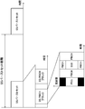
- FIG. 2 is a diagram showing an example of an SS/PBCH block (also referred to as a synchronization signal block, an SS block, an SSB) and an SS burst set (also referred to as a synchronization signal burst set) according to the present embodiment.
- FIG. 2 shows an example in which two SS/PBCH blocks are included in an SS burst set that is periodically transmitted, and the SS/PBCH block is composed of 4 consecutive OFDM symbols.
- the SS/PBCH block is a unit block including at least a synchronization signal (PSS, SSS) and/or PBCH. Transmitting the signal/channel included in the SS/PBCH block is expressed as transmitting the SS/PBCH block.
- the base station device 3 transmits a synchronization signal and/or a PBCH using one or more SS/PBCH blocks in the SS burst set, the base station device 3 may use an independent downlink transmission beam for each SS/PBCH block. Good.
- PSS, SSS, and PBCH are time/frequency multiplexed in one SS/PBCH block.
- the order in which PSS, SSS, and/or PBCH are multiplexed in the time domain may be different from the example shown in FIG.
- SS burst set may be sent periodically.
- a cycle to be used for initial access and a cycle set for the connected (Connected or RRC_Connected) terminal device may be defined.
- the cycle set for the connected (Connected or RRC_Connected) terminal device may be set in the RRC layer.
- the period set for the connected (Connected or RRC_Connected) terminal is the period of the radio resources in the time domain that may potentially be transmitted, and whether the base station device 3 actually transmits You may decide.
- the cycle used for initial access may be defined in advance in a specification or the like.
- the SS burst set may be determined based on the system frame number (SFN: System Frame Number). Further, the start position (boundary) of the SS burst set may be determined based on the SFN and the cycle.
- SFN System Frame Number
- An SS/PBCH block is assigned an SSB index (may be referred to as SSB/PBCH block index) according to the temporal position in the SS burst set.
- the terminal device 1 calculates the SSB index based on the information of the PBCH included in the detected SS/PBCH block and/or the information of the reference signal.
- -SS/PBCH blocks with the same relative time in each SS burst set in multiple SS burst sets are assigned the same SSB index.
- SS/PBCH blocks with the same relative time within each SS burst set in multiple SS burst sets may be assumed to be QCL (or have the same downlink transmit beam applied).
- antenna ports in SS/PBCH blocks with the same relative time in each SS burst set in multiple SS burst sets may be assumed to be QCL with respect to average delay, Doppler shift, and spatial correlation.
- SS/PBCH blocks to which the same SSB index is assigned may be assumed to be QCL with respect to average delay, average gain, Doppler spread, Doppler shift, and spatial correlation.
- the settings corresponding to one or more SS/PBCH blocks that are QCLs (or may be reference signals) may be referred to as QCL settings.
- the number of SS/PBCH blocks (which may be referred to as the number of SS blocks or the number of SSBs) is, for example, the number of SS/PBCH blocks in the SS burst or SS burst set, or in the cycle of SS/PBCH blocks. May be defined. Further, the number of SS/PBCH blocks may indicate the number of beam groups for cell selection in the SS burst, the SS burst set, or the cycle of the SS/PBCH block. Here, the beam group may be defined as the number of different SS/PBCH blocks or the number of different beams included in the SS burst, or the set of SS bursts, or the period of the SS/PBCH block.
- the reference signals described in this embodiment are downlink reference signals, synchronization signals, SS/PBCH blocks, downlink DM-RSs, CSI-RSs, uplink reference signals, SRSs, and/or uplink DM-. Including RS.
- the downlink reference signal, the synchronization signal and/or the SS/PBCH block may be referred to as a reference signal.
- Reference signals used in the downlink include downlink reference signals, synchronization signals, SS/PBCH blocks, downlink DM-RSs, CSI-RSs, and the like.
- the reference signal used in the uplink includes an uplink reference signal, SRS, and/or uplink DM-RS.
- the reference signal may be used for radio resource measurement (RRM). Further, the reference signal may be used for beam management.
- RRM radio resource measurement
- the reference signal may be used for beam management.
- Beam management includes analog and/or digital beams in a transmitting device (the base station device 3 in the case of downlink and the terminal device 1 in the case of uplink) and a receiving device (the terminal device 1 in the case of downlink).
- a transmitting device the base station device 3 in the case of downlink and the terminal device 1 in the case of uplink
- a receiving device the terminal device 1 in the case of downlink
- the uplink it is the procedure of the base station apparatus 3 and/or the terminal apparatus 1 for adjusting the directivity of the analog and/or digital beams in the base station apparatus 3 to obtain the beam gain.
- the procedure for configuring, setting or establishing the beam pair link may include the following procedure. ⁇ Beam selection ⁇ Beam refinement ⁇ Beam recovery
- the beam selection may be a procedure for selecting a beam in communication between the base station device 3 and the terminal device 1.
- the beam improvement may be a procedure of selecting a beam having a higher gain or changing the beam between the base station device 3 and the terminal device 1 optimally by moving the terminal device 1.
- the beam recovery may be a procedure for reselecting a beam when the quality of the communication link is deteriorated due to a blockage caused by a blocking object or a person passing in the communication between the base station device 3 and the terminal device 1.
- Beam management may include beam selection and beam refinement.
- Beam recovery may include the following procedures. ⁇ Detection of beam failure ⁇ Finding a new beam ⁇ Sending beam recovery request ⁇ Monitoring response to beam recovery request
- RSRP Reference Signal Received Power
- CSI-RS resource index CRI: CSI-RS Resource Index
- DMRS reference signal
- the base station apparatus 3 instructs the CRI or SS/PBCH time index when instructing the beam to the terminal apparatus 1, and the terminal apparatus 1 receives based on the instructed CRI or SS/PBCH time index.
- the terminal device 1 may set and receive the spatial filter based on the instructed CRI or the time index of the SS/PBCH.
- the terminal device 1 may receive by using the assumption of a pseudo co-location (QCL).
- a signal (antenna port, sync signal, reference signal, etc.) is "QCL" with another signal (antenna port, sync signal, reference signal, etc.), or "the assumption of QCL is used" means that a signal is Can be interpreted as being associated with another signal.
- Two antenna ports are said to be QCL if the Long Term Property of the channel on which one symbol on one antenna port is carried can be inferred from the channel on which one symbol on the other antenna port is carried. ..
- Long-term characteristics of the channel include one or more of delay spread, Doppler spread, Doppler shift, average gain, and average delay. For example, when the antenna port 1 and the antenna port 2 are QCL with respect to the average delay, it means that the reception timing of the antenna port 2 can be inferred from the reception timing of the antenna port 1.
- the QCL extended to the space may be newly defined.
- the arrival angle AoA (Angle of Arrival), ZoA (Zenith angle of Arrival), etc.
- Angle Spread for example ASA (Angle Spread Arrival) and ZSA (Zenith angle Spread ofArrival)
- sending angle AoD, ZoD, etc.
- Angle Spread for example ASD (Angle Spread of Departure) and ZSD ( ZenithangleSpread Departure)
- spatial correlation SpatialCorrelation
- reception spatial parameters reception spatial parameters.
- the reception beam (reception spatial filter) that receives the signal from the antenna port 1 receives the signal from the antenna port 2 from the reception beam. It means that the beam can be inferred.
- QCL type a combination of long-term characteristics that may be considered to be QCL may be defined.
- the following types may be defined.
- -Type A Doppler shift, Doppler spread, average delay
- delay spread-Type B Doppler shift
- Doppler spread-Type C Average delay
- Doppler shift-Type D Reception spatial parameter
- the above-mentioned QCL type sets the assumption of QCL of one or two reference signals and PDCCH or PDSCH DMRS in the RRC and/or MAC layer and/or DCI as a transmission configuration indication (TCI) and/or You may instruct.
- TCI transmission configuration indication
- the terminal device 1 determines that the PDCCH DMRS
- the Doppler shift, the Doppler spread, the average delay, the delay spread, the reception space parameter and the long-term characteristics of the channel are regarded as the DMRS of the PDCCH to receive the synchronization and the propagation path. You may make an estimate.
- the reference signal (SS/PBCH block in the above example) designated by the TCI is the source reference signal, and the reference is influenced by the long-term characteristic inferred from the long-term characteristic of the channel when the source reference signal is received.
- the signal (PDCCH DMRS in the above example) may be referred to as the target reference signal.
- the TCI may have one or more TCI states in RRC and a combination of a source reference signal and a QCL type for each state, and may be instructed to the terminal device 1 by the MAC layer or DCI.
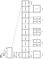
- subframe Although referred to as a subframe in this embodiment, it may be referred to as a resource unit, a radio frame, a time section, a time interval, or the like.
- FIG. 3 is a diagram showing an example of a schematic configuration of uplink and downlink slots according to the first embodiment of the present invention.
- Each radio frame is 10 ms long.
- Each radio frame is composed of 10 subframes and W slots.
- one slot is composed of X OFDM symbols. That is, the length of one subframe is 1 ms.
- NCP Normal Cyclic Prefix
- the uplink slot is similarly defined, and the downlink slot and the uplink slot may be defined separately.
- the bandwidth of the cell in FIG. 3 may be defined as a part of the bandwidth (BWP: BandWidth Part).
- the slot may be defined as a transmission time interval (TTI: Transmission Time Interval). Slots may not be defined as TTIs.
- the TTI may be a transport block transmission period.
- the signal or physical channel transmitted in each of the slots may be represented by a resource grid.
- the resource grid is defined by a plurality of subcarriers and a plurality of OFDM symbols for each numerology (subcarrier spacing and cyclic prefix length) and each carrier.
- the number of subcarriers forming one slot depends on the downlink and uplink bandwidths of the cell.
- Each of the elements in the resource grid is called a resource element. Resource elements may be identified using subcarrier numbers and OFDM symbol numbers.
- one physical resource block is, for example, 12 (the number of OFDM symbols included in one slot)*4 (included in one subframe in the time domain).
- Number of slots) 48 consecutive OFDM symbols and 12*Nmax, ⁇ consecutive subcarriers in the frequency domain. That is, the resource grid is composed of (48*12*Nmax, ⁇ ) resource elements.
- Reference resource blocks, common resource blocks, physical resource blocks, and virtual resource blocks are defined as resource blocks.
- One resource block is defined as 12 consecutive subcarriers in the frequency domain.
- the reference resource block is common to all subcarriers, and may constitute a resource block with a subcarrier interval of 15 kHz, for example, and may be numbered in ascending order.
- Subcarrier index 0 in reference resource block index 0 may be referred to as reference point A (point A) (may be simply referred to as “reference point”).
- the common resource block is a resource block numbered in ascending order from 0 in each subcarrier interval setting ⁇ from the reference point A.
- the resource grid described above is defined by this common resource block.
- the physical resource blocks are resource blocks numbered in ascending order from 0 included in the band part (BWP) described later, and the physical resource blocks are in ascending order from 0 included in the band part (BWP). It is a numbered resource block.
- a physical uplink channel is first mapped to a virtual resource block.
- the virtual resource block is then mapped to the physical resource block.
- the resource block may be a virtual resource block, a physical resource block, a common resource block, or a reference resource block.
- the subcarrier interval setting ⁇ As mentioned above, NR supports one or more OFDM numerologies.
- slots are counted in ascending order from 0 to N ⁇ subframe, ⁇ _ ⁇ slot ⁇ -1 in a subframe, and 0 to N ⁇ frame, ⁇ _ ⁇ slot in a frame.
- ⁇ -1 is counted in ascending order.
- N ⁇ slot ⁇ _ ⁇ symb ⁇ consecutive OFDM symbols in the slot based on the slot settings and the cyclic prefix.
- N ⁇ slot ⁇ _ ⁇ symb ⁇ is 14.
- the start of slot n ⁇ _ ⁇ s ⁇ in a subframe is the start and time of the n ⁇ _ ⁇ s ⁇ *N ⁇ slot ⁇ _ ⁇ symb ⁇ th OFDM symbol in the same subframe. Is aligned with.
- FIG. 4 is a diagram showing the relationship between subframes, slots, and minislots in the time domain. As shown in the figure, three types of time units are defined.
- the subframe is 1 ms regardless of the subcarrier interval, the number of OFDM symbols included in the slot is 7 or 14, and the slot length differs depending on the subcarrier interval.
- the subcarrier interval is 15 kHz, one subframe includes 14 OFDM symbols.
- the downlink slot may be referred to as PDSCH mapping type A.
- the uplink slot may be referred to as PUSCH mapping type A.
- a minislot (may be referred to as a subslot) is a time unit composed of a smaller number of OFDM symbols than the number of OFDM symbols included in one slot.
- the figure shows the case where the minislot is composed of two OFDM symbols as an example.
- the OFDM symbols in a minislot may match the OFDM symbol timing that makes up the slot.
- the minimum unit of scheduling may be a slot or a minislot.
- assigning minislots may be referred to as non-slot based scheduling.
- scheduling a minislot may be expressed as scheduling a resource in which a relative time position between a reference signal and a start position of data is fixed.
- the downlink minislot may be referred to as PDSCH mapping type B.
- the uplink minislot may be referred to as PUSCH mapping type B.
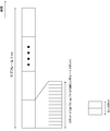
- FIG. 5 is a diagram showing an example of the slot format.
- the slot length is 1 ms at a subcarrier interval of 15 kHz is shown as an example.
- D indicates the downlink and U indicates the uplink.
- U indicates the uplink.
- a certain time period for example, the minimum time period that must be assigned to one UE in the system
- It may include one or more of a downlink symbol, a flexible symbol, and an uplink symbol. Note that these ratios may be predetermined as a slot format. Further, it may be defined by the number of downlink OFDM symbols included in the slot or the start position and end position in the slot.
- scheduling a slot may be expressed as scheduling a resource in which the relative time position between the reference signal and the slot boundary is fixed.
- the terminal device 1 may receive a downlink signal or a downlink channel with a downlink symbol or a flexible symbol.
- the terminal device 1 may transmit an uplink signal or a downlink channel with an uplink symbol or a flexible symbol.
- 5A may also be referred to as a certain time section (for example, a minimum unit of time resources that can be assigned to one UE, a time unit, or the like. Further, a plurality of minimum units of time resources are bundled and referred to as a time unit.
- 5B is an example in which uplink scheduling is performed via the PDCCH in the first time resource, and the processing delay of the PDCCH and the downlink are used.
- the uplink signal is transmitted via the flexible symbol including the uplink switching time and the generation of the transmission signal.
- the uplink signal may be used for transmitting HARQ-ACK and/or CSI, that is, UCI.
- FIG. 5(d) is used for transmission of PDCCH and/or PDSCH in the first time resource, and has processing delay, downlink to uplink switching time, and uplink PUSCH and/or via a gap for generation of a transmission signal.
- the uplink signal may be used for transmitting uplink data, that is, UL-SCH.
- FIG. 5E is an example in which all are used for uplink transmission (PUSCH or PUCCH).
- the downlink part and the uplink part described above may be composed of a plurality of OFDM symbols as in LTE.
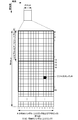
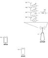
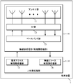
- FIG. 6 is a diagram showing an example of beamforming.
- a plurality of antenna elements are connected to one transmission unit (TXRU: Transceiver unit) 50, the phase is controlled by the phase shifter 51 for each antenna element, and by transmitting from the antenna element 52, the transmission signal can be transmitted in any direction.
- the beam can be aimed.
- TXRU may be defined as an antenna port, and in the terminal device 1, only the antenna port may be defined.
- directivity can be directed in an arbitrary direction, so that the base station device 3 can communicate with the terminal device 1 using a beam having a high gain.
- BWP Bandwidth part
- BWP is also referred to as carrier BWP.
- BWP may be set for each of the downlink and the uplink.
- BWP is defined as a set of contiguous physical resources selected from a contiguous subset of common resource blocks.
- the terminal device 1 can set up to four BWPs in which one downlink carrier BWP (DL BWP) is activated at a certain time.
- DL BWP downlink carrier BWP
- UL BWP uplink carrier BWP
- BWP may be set in each serving cell. At this time, the fact that one BWP is set in a certain serving cell may be expressed as the case where no BWP is set. Further, the setting of two or more BWPs may be expressed as the BWP being set.
- BWP switching for a serving cell is used to activate an inactive (deactivated) BWP and deactivate an active (activated) BWP. To be done.
- BWP switching for a serving cell is controlled by PDCCH indicating downlink allocation or uplink grant.
- BWP switching for a serving cell may also be controlled by the BWP inactivity timer, RRC signaling, or by the MAC entity itself at the start of the random access procedure.
- SpCell PCell or PSCell
- SCell SpCell
- one BWP is first active without receiving PDCCH indicating downlink allocation or uplink grant.
- the first active DL BWP (first active DL BWP) and the UL BWP (first active UL BWP) may be specified in the RRC message sent from the base station device 3 to the terminal device 1.
- the active BWP for a certain serving cell is designated by the RRC or PDCCH sent from the base station device 3 to the terminal device 1.
- the first active DL BWP (first active DL BWP) and the UL BWP (first active UL BWP) may be included in the message 4.
- DL BWP and UL BWP are paired, and BWP switching is common to UL and DL.
- the MAC entity of the terminal device 1 applies the normal process. Normal processing includes transmitting UL-SCH, transmitting RACH, monitoring PDCCH, transmitting PUCCH, transmitting SRS, and receiving DL-SCH.
- the MAC entity of the terminal device 1 does not transmit the UL-SCH, does not transmit the RACH, does not monitor the PDCCH, does not transmit the PUCCH, Does not send SRS and does not receive DL-SCH. If a serving cell is deactivated, no active BWP may be present (eg, active BWP is deactivated).
- the BWP information element (IE) included in the RRC message (system information notified or information sent by the dedicated RRC message) is used to set the BWP.
- the RRC message transmitted from the base station device 3 is received by the terminal device 1.
- the network (such as the base station device 3) has at least one downlink BWP and one (if the serving cell is configured for uplink) or two (supplementary uplink in the Appendix). Is set to the terminal device 1, at least an initial BWP (initial BWP) including an uplink BWP (for example, is used).
- the network may configure additional uplink BWP or downlink BWP for certain serving cells.
- the BWP setting is divided into an uplink parameter and a downlink parameter.
- the BWP setting is divided into a common parameter and a dedicated parameter.
- Common parameters (such as BWP uplink common IE and BWP downlink common IE) are cell-specific.
- the common parameters of the initial BWP of the primary cell are also provided in the system information.
- the network provides common parameters on dedicated signals.
- the BWP is identified by the BWP ID.
- the initial BWP has a BWP ID of 0.
- the BWP IDs of other BWPs take values from 1 to 4.
- the initial DL BWP (initial active DL BWP, initial DL BWP) is the control resource set (CORESET) for the type 0 PDCCH common search space. It may be defined by the position and number of consecutive PRBs, subcarrier spacing, and cyclic prefix for PDCCH reception in. The positions of the consecutive PRBs start from the PRB with the smallest index and end with the PRB with the largest index among the PRBs of the control resource set for the type 0 PDCCH common search space.
- the initial DL BWP may be indicated by the upper layer parameter initialDownlinkBWP.
- the upper layer parameter initialDownlinkBWP may be included in SIB1 (systemInformationBlockType1, ServingCellConfigCommonSIB) or ServingCellConfigCommon.
- SIB1 systemInformationBlockType1, ServingCellConfigCommonSIB
- ServingCellConfigCommon SIB is used to set the cell-specific parameter of the serving cell for the terminal device 1 in the SIB1.
- the size of the initial DL BWP is the number of resource blocks of the control resource set (CORESET#0) for the type 0 PDCCH common search space. It may be.
- the size of the initial DL BWP may be given by the locationAndBandwidth included in the upper layer parameter initialDownlinkBWP.
- the upper layer parameters locationAndBandwidth may indicate the position and bandwidth of the frequency domain of the initial DL BWP.
- multiple DL BWPs may be set for the terminal device 1. Then, of the DL BWPs set for the terminal device 1, the default DL BWP can be set by the upper layer parameter defaultDownlinkBWP-Id. When the upper layer parameter defaultDownlinkBWP-Id is not provided to the terminal device 1, the default DL BWP is the initial DL BWP.
- An initial UL BWP may be provided to the terminal device 1 by SIB1 (systemInformationBlockType1) or initialUplinkBWP.
- the information element initialUplinkBWP is used to set the initial UL BWP.
- the terminal device 1 may be set (provided) with an initial UL BWP (initial active UL BWP) by the upper layer parameter initialUplinkBWP.
- the terminal device 1 uses the initialUplinkBWP included in the upper-layer parameter supplementaryUplink to set the initial UL on the supplementary uplink carrier. BWP may be set.
- Control resource set (CORESET) in this embodiment will be described below.
- Control resource set (CORESET, Control resource set) is a time and frequency resource for searching downlink control information.
- the setting information of CORESET includes information for identifying the CORESET identifier (ControlResourceSetId, CORESET-ID) and the frequency resource of CORESET.
- the information element ControlResourceSetId (identifier of CORESET) is used to specify the control resource set in a certain serving cell.
- the CORESET identifier is used between BWPs in a serving cell.
- the CORESET identifier is unique between BWPs in the serving cell.
- the number of CORESETs for each BWP is limited to 3, including the initial CORESET. In a certain serving cell, the value of the identifier of CORESET takes a value from 0 to 11.
- CORESET#0 The control resource set specified by the CORESET identifier 0 (ControlResourceSetId 0) is called CORESET#0.
- CORESET#0 may be set by pdchch-ConfigSIB1 included in MIB or PDCCH-ConfigCommon included in ServingCellConfigCommon. That is, the setting information of CORESET#0 may be pdcch-ConfigSIB1 included in MIB or PDCCH-ConfigCommon included in ServingCellConfigCommon.
- the setting information of CORESET#0 may be set by controlResourceSetZero included in PDCCH-ConfigSIB1 or PDCCH-ConfigCommon.
- the information element controlResourceSetZero is used to indicate CORESET#0 (common CORESET) of the initial DL BWP.
- CORESET indicated by pdcch-ConfigSIB1 is CORESET#0.
- the information element pdcch-ConfigSIB1 in the MIB or the dedicated configuration is used to set the initial DL BWP.
- the CORESET setting information pdcch-ConfigSIB1 for CORESET#0 the CORESET identifier, the CORESET frequency resource (for example, the number of consecutive resource blocks), and the time resource (the number of consecutive symbols) are explicitly specified.
- the frequency resource (for example, the number of consecutive resource blocks) and the time resource (the number of consecutive symbols) of CORESET with respect to CORESET#0 are implicitly indicated by the information included in pdcch-ConfigSIB1. Can be specified.
- the information element PDCCH-ConfigCommon is used to set cell-specific PDCCH parameters provided in SIB. Further, the PDCCH-ConfigCommon may be provided at the time of handover and addition of PSCell and/or SCell.
- the setting information of CORESET#0 is included in the setting of the initial BWP. That is, the setting information of CORESET#0 does not need to be included in the setting of BWP other than the initial BWP.
- the controlResourceSetZero corresponds to 4 bits (for example, 4 bits of MSB and 4 bits of most significant bit) of pdcch-ConfigSIB1.
- CORESET#0 is a control resource set for the type 0 PDCCH common search space.
- the setting information of the additional common CORESET may be set by the commonControlResourceSet included in the PDCCH-ConfigCommon. Also, the additional common CORESET configuration information may be used to specify additional common CORESET for system information and/or paging procedures. The setting information of the additional common CORESET may be used to specify the additional common CORESET used in the random access procedure. The setting information of the additional common CORESET may be included in the setting of each BWP. The identifier of CORESET shown in commonControlResourceSet takes a value other than 0.
- the common CORESET may be a CORESET used for the random access procedure (for example, an additional common CORESET). Further, in the present embodiment, the common CORESET may include CORESET#0 and/or CORESET set by the additional common CORESET setting information. That is, common CORESET may include CORESET#0 and/or additional common CORESET. CORESET#0 may be referred to as common CORESET#0.
- the terminal device 1 and the BWP other than the BWP in which the common CORESET is set may also refer to (acquire) the setting information of the common CORESET.
- the setting information of one or more CORESETs may be set by PDCCH-Config.
- the information element PDCCH-Config is used to set UE-specific PDCCH parameters (eg, CORSET, search space, etc.) for a certain BWP.
- PDCCH-Config may be included in the settings of each BWP.
- the common CORESET setting information indicated by MIB is pdcch-ConfigSIB1
- the common CORESET setting information indicated by PDCCH-ConfigCommon is controlResourceSetZero
- the common CORESET indicated by PDCCH-ConfigCommon is additional.
- the setting information of the common CORESET is commonControlResourceSet.
- the setting information of one or more CORESETs (UE-specifically configured Control Resource Sets, UE-specific CORESET) indicated by PDCCH-Config is controlResourceSetToAddModList.
- the search space is defined to search for PDCCH candidates (PDCCH candidates).
- the searchSpaceType included in the search space setting information indicates whether the search space is a common search space (Common Search Space, CSS) or a UE-specific search space (UE-specific Search Space, USS).
- the UE-specific search space is at least derived from the value of C-RNTI set by the terminal device 1. That is, the UE-specific search space is individually derived for each terminal device 1.
- the common search space is a common search space among a plurality of terminal devices 1, and is composed of CCEs (Control Channel Elements) having a predetermined index.
- the CCE is composed of a plurality of resource elements.
- the search space setting information includes information on the DCI format monitored in the search space.
- the search space setting information includes the CORESET identifier specified by the CORESET setting information.
- the CORESET specified by the CORESET identifier included in the search space setting information is associated with the search space.
- CORESET associated with the search space is CORESET specified by the identifier of CORESET included in the search space.
- the DCI format indicated by the setting information of the search space is monitored by the associated CORESET.
- Each search space is associated with one CORESET.
- the search space setting information for the random access procedure may be set by ra-SearchSpace. That is, the DCI format to which the CRC scrambled by RA-RNTI or TC-RNTI is added in CORESET associated with ra-SearchSpace is monitored.
- the terminal device 1 monitors a set of PDCCH candidates in one or more CORESETs arranged in each active serving cell configured to monitor the PDCCH.
- the set of PDCCH candidates corresponds to one or more search space sets. Monitoring refers to decoding each PDCCH candidate depending on the DCI format or formats being monitored.
- a set of PDCCH candidates monitored by the terminal device 1 is defined by a PDCCH search space set.
- One search space set is a common search space set or a UE-specific search space set. In the above, the search space set is called a search space, the common search space set is called a common search space, and the UE-specific search space set is called a UE-specific search space.
- the terminal device 1 monitors PDCCH candidates with one or more of the following search space sets.
- -Type 0 PDCCH common search space set This search space set is indicated by pdcch-ConfigSIB1 or PDCCH-ConfigCommon indicated by MIB, which is an upper layer parameter.
- the search space SIB1 (searchSpaceSIB1) or the search space zero (searchSpaceZero) included in the PDCCH-ConfigCommon is set. This search space is for monitoring the SI-RNRI scrambled CRC DCI format in the primary cell.
- -Type 0A PDCCH common search space set (type 0A-PDCCH common search space set): This search space set is set by the search space (searchSpaceOtherSystemInformation) indicated by PDCCH-ConfigCommon, which is a parameter of the upper layer. To be done.
- This search space is for monitoring the SI-RNRI scrambled CRC DCI format in the primary cell.
- -Type 1 PDCCH common search space set (a Type1-PDCCH common search space set): This search space set is a search for a random access procedure indicated by PDCCH-ConfigCommon, which is an upper layer parameter. Set by space (ra-SearchSpace). This search space is for monitoring the DCI format of the CRC scrambled with RA-RNRI or TC-RNTI in the primary cell.
- the Type 1 PDCCH common search space set is a search space set for a random access procedure.
- Type2-PDCCH common search space set This search space set is a search space for a paging procedure indicated by PDCCH-ConfigCommon, which is an upper layer parameter. Set by (pagingSearchSpace). This search space is for monitoring the DCI format of the P-RNTI scrambled CRC in the primary cell.
- -Type 3 PDCCH common search space set (a Type3-PDCCH common search space set): This search space set is a search space whose search space type indicated by PDCCH-Config, which is an upper layer parameter, is common. Set by (SearchSpace).
- This search space is for monitoring the DCI format of the INT-RNTI, SFI-RNTI, TPC-PUSCH-RNTI, TPC-PUCCH-RNTI, or TPC-SRS-RNTI scrambled CRC.
- For the primary license it is for monitoring the DCI format of the CRC scrambled with C-RNTI, CS-RNTI(s), or MCS-C-RNTI.
- -UE-specific search space set In this search space set, the search space type indicated by PDCCH-Config, which is an upper layer parameter, is set by the UE-specific search space (SearchSpace). ..
- This search space is for monitoring DCI format of CRC scrambled with C-RNTI, CS-RNTI(s), or MCS-C-RNTI.
- the terminal device 1 monitors the PDCCH candidates for the DCI format 0_0 and the DCI format 1_0 having the C-RNTI or the CS-RNTI with the one or more search space sets. May be.
- the BWP setting information is divided into DL BWP setting information and UL BWP setting information.
- the BWP setting information includes an information element bwp-Id (BWP identifier).
- the BWP identifier included in the DL BWP setting information is used to identify (reference) the DL BWP in a certain serving cell.
- the BWP identifier included in the UL BWP setting information is used to identify (reference) the UL BWP in a certain serving cell.
- the BWP identifier is given to each of the DL BWP and UL BWP.
- the identifier of the BWP corresponding to the DL BWP may be referred to as the DL BWP index.
- the BWP identifier corresponding to the UL BWP may be referred to as the UL BWP index (ULBWP index).
- the initial DL BWP is referenced by the DL BWP identifier 0.
- the initial UL BWP is referenced by the UL BWP identifier 0.
- maxNrofBWPs is the maximum number of BWPs per serving cell and is 4.
- the value of the other BWP identifier takes a value from 1 to 4.
- Other upper layer setting information is associated with a specific BWP using the BWP identifier. Having DL BWP and UL BWP having the same BWP identifier may mean that DL BWP and UL BWP are paired.
- the terminal device 1 may be configured with one primary cell and up to 15 secondary cells.
- the terminal device 1 may decode (receive) the corresponding PDSCH by detecting the PDCCH including the DCI format 1_0, the DCI format 1_1, or the DCI format 1_2.
- the corresponding PDSCH is scheduled (indicated) by its DCI format (DCI).
- DCI DCI format
- the start position (start symbol) of the scheduled PDSCH is referred to as S.
- the starting symbol S of the PDSCH may be the first symbol in which the PDSCH is transmitted (mapped) in a certain slot.
- the start symbol S corresponds to the start of the slot. For example, when the value of S is 0, the terminal device 1 may receive the PDSCH from the first symbol in a certain slot.
- the terminal device 1 may receive the PDSCH from the third symbol of a certain slot.
- L be the number of consecutive (consecutive) symbols of the PDSCH. The number L of consecutive symbols is counted from the start symbol S. The determination of S and L assigned to PDSCH will be described later.
- the PDSCH mapping type has PDSCH mapping type A and PDSCH mapping type B.
- S takes values from 0 to 3.
- L takes a value from 3 to 14.
- the sum of S and L takes values from 3 to 14.
- S takes values from 0 to 12.
- L takes one value from ⁇ 2, 4, 7 ⁇ .
- the sum of S and L takes a value from 2 to 14.
- the location of the DMRS symbol for PDSCH depends on the type of PDSCH mapping.
- the position of the first DMRS symbol for PDSCH depends on the type of PDSCH mapping.
- the position of the first DMRS symbol may be indicated in the upper layer parameter dmrs-TypeA-Position. That is, the upper layer parameter dmrs-TypeA-Position is used to indicate the position of the first DMRS for PDSCH or PUSCH.
- dmrs-TypeA-Position may be set to either'pos2' or'pos3'.
- the position of the first DMRS symbol for PDSCH may be the third symbol in the slot.
- the position of the first DMRS symbol for PDSCH may be the fourth symbol in the slot.
- S can take a value of 3 only when dmrs-TypeA-Position is set to'pos3'. That is, when dmrs-TypeA-Position is set to'pos2', S takes a value from 0 to 2.
- the position of the first DMRS symbol is the first symbol of the PDSCH assigned.
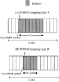
- FIG. 7 is a diagram showing an example of the PDSCH mapping type according to the present embodiment.
- FIG. 7A is a diagram showing an example of PDSCH mapping type A.
- the S of PDSCH to be assigned is 3.
- the L of PDSCH allocated is 7.
- the position of the first DMRS symbol for PDSCH is the fourth symbol in the slot. That is, dmrs-TypeA-Position is set to'pos3'.
- FIG. 7B is a diagram showing an example of PDSCH mapping type A.
- the S of PDSCH to be assigned is 4.
- the L of PDSCH allocated is 4.
- the position of the first DMRS symbol for PDSCH is the first symbol to which PDSCH is assigned.
- the base station device 3 may schedule the terminal device 1 to receive PDSCH by DCI.
- the terminal device 1 may receive the PDSCH by detecting the DCI addressed to the terminal device 1.
- the terminal device 1 first determines the resource allocation table to be applied to the PDSCH.
- the resource allocation table includes one or more PDSCH time domain resource allocation configurations.
- the terminal device 1 may select one PDSCH time domain resource allocation setting in the determined resource allocation table based on the value indicated in the'Time domain resource assignment' field included in the DCI that schedules the PDSCH.
- the base station device 3 determines the resource allocation of the PDSCH to the terminal device 1, generates the'Time domain resource assignment' field of the value based on the determined resource allocation, and the DCI including the'Time domain resource assignment' field. Is transmitted to the terminal device 1.
- the terminal device 1 identifies the resource allocation in the time direction of PDSCH based on the value of the'Time domain resource assignment' field.
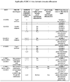
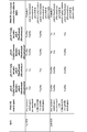
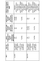
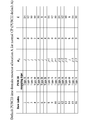
- FIG. 10 is a diagram defining a resource allocation table applied to PDSCH time domain resource allocation.
- the terminal device 1 may determine the resource allocation table to be applied to PDSCH time domain resource allocation based on the table shown in FIG.
- the resource allocation table includes one or more PDSCH time domain resource allocation configurations.
- the resource allocation table is classified into (I) a resource allocation table defined in advance and (II) a resource allocation table configured from an RRC signal of an upper layer.
- the predefined resource allocation table is defined as, for example, a default PDSCH time domain resource allocation A, a default PDSCH time domain resource allocation B, and a default PDSCH time domain resource allocation C.
- a default PDSCH time domain resource allocation D different from the default PDSCH time domain resource allocation A may be defined.
- default PDSCH time domain resource allocation A is default table A
- default PDSCH time domain resource allocation B is default table B
- default PDSCH time domain resource allocation C is default table C
- default PDSCH time domain resource allocation D is default. This is referred to as table D.
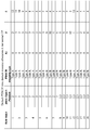
- FIG. 13 is a diagram showing an example of the default table A according to this embodiment.
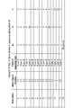
- FIG. 14 is a diagram showing an example of the default table B according to this embodiment.
- FIG. 15 is a diagram showing an example of the default table C according to the present embodiment.
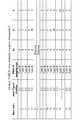
- the number of rows in the default table A is 16, and each row indicates the setting of PDSCH time domain resource allocation.
- each row defines the PDSCH mapping type, the slot offset K 0 between the PDCCH including the DCI and the PDSCH, the start symbol S of the PDSCH in the slot, and the continuous allocation symbol number L.
- the resource allocation table set by the RRC signal of the upper layer is given by the signal pdsch-TimeDomainAllocationList of the upper layer.
- the pdsch-TimeDomainAllocationList includes one or more information elements PDSCH-TimeDomainResourceAllocation.
- PDSCH-TimeDomainResourceAllocation indicates the setting of PDSCH time domain resource allocation.
- PDSCH-TimeDomainResourceAllocation may be used to set a time domain relationship between the PDCCH including the DCI and the PDSCH. That is, pdsch-TimeDomainAllocationList is a list containing one or more information elements.
- One PDSCH-TimeDomainResourceAllocation may be referred to as one entry (or one row).
- pdsch-TimeDomainAllocationList includes a maximum of 16 entries, and any one entry may be used depending on a 4-bit field included in DCI. However, the number of entries included in the pdsch-TimeDomainAllocationList may be different, and the number of bits of the fields included in the DCI associated therewith may be different values.
- K 0 indicates the slot offset between the PDCCH containing the DCI and its PDSCH.
- the terminal device 1 may assume that the value of K 0 is a predetermined value (for example, 0).
- the mappingType indicates whether the corresponding PDSCH mapping type is the PDSCH mapping type A or the PDSCH mapping type B.
- the startSymbolAndLength is an index that gives a valid combination of the start symbol S of the corresponding PDSCH and the number L of consecutively allocated symbols.
- the startSymbolAndLength may be referred to as a start position and length indicator (SLIV).
- SLIV start position and length indicator
- the base station apparatus 3 may set the value of SLIV so that the time domain resource allocation of PDSCH does not exceed the slot boundary.
- the slot offset K 0 and SLIV will be described later.
- the upper layer signal pdsch-TimeDomainAllocationList may be included in the cell-specific RRC parameter pdsch-ConfigCommon and/or the terminal apparatus 1 (UE)-specific RRC parameter pdsch-Config.
- the pdsch-ConfigCommon is used to set cell-specific parameters for PDSCH for a certain BWP.
- the pdsch-Config is used to set a terminal unit 1 (UE) specific parameter for PDSCH for a certain BWP.
- the terminal device 1 may apply different resource allocation tables to PDSCH time domain resource allocation depending on whether the first PDSCH is received or the second PDSCH is received.
- the base station device 3 may apply different resource allocation tables to the PDSCH time domain resource allocation depending on whether the first PDSCH is transmitted or the second PDSCH is transmitted.
- the first PDSCH and the second PDSCH may be PDSCHs that transmit data of different services.
- the first PDSCH may be a PDSCH that transmits eMBB data
- the second PDSCH may be a PDSCH that transmits URLLC data.
- the first PDSCH may be a PDSCH scheduled by the first DCI.
- the second PDSCH may be a PDSCH scheduled by the second DCI.
- the first DCI and the second DCI may be DCIs that schedule data for different services.
- the first DCI may be a DCI that schedules a PDSCH that transmits eMBB data
- the second DCI may be a DCI that schedules a PDSCH that transmits URLLC data.
- the first DCI and the second DCI may be DCIs to which CRCs scrambled with different RNTIs are added.
- the first DCI is the DCI with the CRC scrambled by the first value range C-RNTI
- the second DCI is the second value different from the first value range. It may be a DCI with a CRC scrambled by the range C-RNTI.
- the first DCI is a DCI with a CRC scrambled with any type of RNTI that is a third range of values
- the second DCI is a fourth DCI that is different from the third range of values. It may be a DCI with a CRC scrambled with any type of RNTI that is a range of values.
- the first DCI is a DCI with a CRC scrambled with C-RNTI, MCS-C-RNTI, CS-RNTI, SI-RNTI, RA-RNTI, TC-RNTI and/or P-RNTI.
- the second DCI may be a DCI to which a CRC scrambled by the UC-RNTI is added.
- UC-RNTI is an RNTI that uses a value different from the values available for C-RNTI, MCS-C-RNTI, CS-RNTI, SI-RNTI, RA-RNTI, TC-RNTI and P-RNTI.
- the UC-RNTI may be the RNTI used to control the PDSCH or PUSCH of the data of a predetermined service in one or more slots.
- the first DCI and the second DCI may be DCIs using different DCI formats.
- the first DCI may be DCI using DCI format 1_1 and the second DCI may be DCI using DCI format 1_2.
- the first DCI and the second DCI may be DCI using DCI formats of different sizes.
- the first DCI may be a DCI using the first size DCI format
- the second DCI may be a DCI using a second size DCI format different from the first size.
- the first DCI and the second DCI may be predetermined fields in their respective DCI formats, and may indicate the service applied to the corresponding PDSCH data.
- a field in the DCI format of the first DCI may specify that the corresponding PDSCH carries eMBB data.
- a field in the DCI format of the second DCI may specify that the corresponding PDSCH carries URLLC data.
- the first DCI and the second DCI may be DCIs transmitted in different search spaces and/or different CORESETs.
- the first DCI and the second DCI may be DCIs that schedule PDSCHs of different codebooks.
- the resource allocation table set by the RRC signal of the upper layer may be given by a signal of the upper layer (which may be an information element or an RRC parameter) different from the signal pdsch-TimeDomainAllocationList of the upper layer. For example, it may be given by an upper layer signal pdsch-TimeDomainAllocationList2.
- the base station apparatus 3 may notify the pdsch-TimeDomainAllocationList and/or the pdsch-TimeDomainAllocationList2 by an upper layer signal.
- the terminal device 1 may receive the pdsch-TimeDomainAllocationList and/or the pdsch-TimeDomainAllocationList2 in a higher layer signal.
- pdsch-TimeDomainAllocationList2 includes a maximum of 16 entries, and any one entry may be used depending on a 4-bit field included in DCI.
- K 0 , mappingType, and/or startSymbolAndLength may be indicated in each entry included in pdsch-TimeDomainAllocationList2.
- the values available in K 0 , mappingType, and/or startSymbolAndLength in each entry of pdsch-TimeDomainAllocationList2 may be different than those available in pdsch-TimeDomainAllocationList.
- the value of K 0 available in pdsch-TimeDomainAllocationList may be 0 to 32, and the value of K 0 available in pdsch-TimeDomainAllocationList2 may be 0 to 4.
- mappingType that can be used in pdsch-TimeDomainAllocationList can be mapping type A and mapping type B, and mappingType that can be used in pdsch-TimeDomainAllocationList2 can be only mapping type B.
- pdsch-TimeDomainAllocationList2 may not indicate mappingType.
- the terminal device 1 When the higher-layer signal pdsch-Config includes the pdsch-TimeDomainAllocationList and the PDSCH is scheduled by the first DCI, the terminal device 1 includes the pdsch-config in the pdsch-Config in the PDSCH resource allocation table. -TimeDomainAllocationList may be applied. When the higher-layer signal pdsch-Config includes pdsch-TimeDomainAllocationList2 and the PDSCH is scheduled by the second DCI, the terminal device 1 includes the pdsch-config in the pdsch-Config in the PDSCH resource allocation table. -TimeDomainAllocationList2 may be applied.
- the terminal device 1 does not include the pdsch-TimeDomainAllocationList in the upper layer signals pdsch-Config and pdsch-ConfigCommon, and when the PDSCH is scheduled by the first DCI, the default table is set in the resource allocation table of the PDSCH.
- A may be applied.
- the terminal device 1 does not include the pdsch-TimeDomainAllocationList2 in the upper layer signals pdsch-Config and pdsch-ConfigCommon, and when the PDSCH is scheduled by the second DCI, the default table is set in the resource allocation table of the PDSCH. D may be applied.
- the terminal device 1 may use different default tables for the first DCI and the second DCI when pdsch-TimeDomainAllocationList and/or pdsch-TimeDomainAllocationList2 are not set in the upper layer signal.
- the terminal device 1 may use the same default table for the first DCI and the second DCI when pdsch-TimeDomainAllocationList and/or pdsch-TimeDomainAllocationList2 is not set in the upper layer signal.
- FIG. 16 is a diagram showing an example of calculating SLIV.
- FIG. 16 14 is the number of symbols included in one slot.
- FIG. 16 shows an example of calculating SLIV in the case of NCP (Normal Cyclic Prefix).
- the value of SLIV is calculated based on the number of symbols included in the slot, the start symbol S, and the number L of consecutive symbols.
- the value of L is 1 or more and does not exceed (14-S).
- 6 and 12 are used instead of the values 7 and 14 in FIG.
- the slot offset K 0 will be described below.
- K 0 is the number of slots based on the PDSCH subcarrier spacing. K 0 can take values from 0 to 32. In a certain subframe or frame, slot numbers are counted in ascending order from 0.
- the slot number n of the subcarrier interval setting of 15 kHz corresponds to the slot numbers 2n and 2n+1 of the subcarrier interval setting of 30 kHz.
- the slot assigned to the PDSCH is given by floor(n* 2 ⁇ PDSCH / 2 ⁇ PDCCH )+K 0 .
- the function floor(A) outputs the largest integer that does not exceed A.
- n is a slot in which the PDCCH that schedules the PDSCH is detected.
- ⁇ PDSCH is a subcarrier interval setting for PDSCH .
- ⁇ PDCCH is a subcarrier interval setting for PDCCH .
- the terminal device 1 may determine a resource allocation table to be applied to PDSCH time domain resource allocation based on a plurality of elements.
- the terminal device 1 may determine the resource allocation table to be applied to the PDSCH scheduled by DCI based on at least some or all of the following elements (A) to (F).
- the type of RNTI that scrambles the CRC added to DCI is SI-RNTI, RA-RNTI, TC-RNTI, P-RNTI, C-RNTI, MCS-C-RNTI, or CS-. Either of the RNTIs.
- the type of search space in which DCI is detected is common search space or UE-specific search space.
- the common search space includes a type 0 common search space, a type 1 common search space, and a type 2 common search space.
- the terminal device 1 may detect DCI in any common search space associated with CORESET#0. A CRC scrambled by any one of C-RNTI, MCS-C-RNTI, and CS-RNTI is added to the detected DCI. Then, the terminal device 1 may determine the resource allocation table to be applied to the PDSCH scheduled by the DCI. When pdsch-ConfigCommon for the terminal device 1 includes pdsch-TimeDomainAllocationList, the terminal device 1 may determine the resource allocation table set from the RRC signal of the upper layer. The resource allocation table is given by pdsch-TimeDomainAllocationList included in pdsch-ConfigCommon.
- the terminal device 1 may determine the default table A. That is, the terminal device 1 may apply the determination of PDSCH time domain resource allocation using the default table A indicating the configuration of PDSCH time domain resource allocation.
- the terminal device 1 may detect the DCI in any common search space that is not associated with CORESET#0. A CRC scrambled by any of C-RNTI, MCS-C-RNTI, or CS-RNTI is added to the detected DCI. Then, the terminal device 1 may determine the resource allocation table to be applied to the PDSCH scheduled by the DCI. When pdsch-Config includes pdsch-TimeDomainAllocationList for the terminal device 1, the terminal device 1 assigns the resource allocation table applied to the PDSCH time domain resource allocation from the pdsch-TimeDomainAllocationList provided by pdsch-Config. You may decide on the table.
- the terminal device 1 uses the pdsch-ConfigL, which is provided in the pdsch-ConfigL, in the pdsch-ConfigL, in which the pdsch-ConfigPD is used in the pdsch-Config PD, and whether or not the pdsch-ConfigCommon includes the pdsch-TimeDomainAllocationList. It may be applied to the determination of area resource allocation.
- the terminal device 1 uses the resource allocation table to apply PDSCH time domain resource allocation to the on-cod on-cod on It may be determined in the resource allocation table given from the provided pdsch-TimeDomainAllocationList. That is, the terminal device 1 uses pdsch-TimeDomainAllocationList provided by pdsch-ConfigCommon to apply the PDSCH time domain resource allocation determination.
- the terminal device 1 uses the resource allocation table to apply PDSCH time domain resource allocation to the default table A. You may decide.
- the terminal device 1 may detect DCI in the UE-specific search space. A CRC scrambled by any of C-RNTI, MCS-C-RNTI, or CS-RNTI is added to the detected DCI. Then, the terminal device 1 may determine the resource allocation table to be applied to the PDSCH scheduled by the DCI. When pdsch-Config includes pdsch-TimeDomainAllocationList for the terminal device 1, the terminal device 1 assigns the resource allocation table applied to the PDSCH time domain resource allocation from the pdsch-TimeDomainAllocationList provided by pdsch-Config. You may decide on the table.
- the terminal device 1 uses the pdsch-ConfigL, which is provided in the pdsch-ConfigL, in the pdsch-ConfigL, in which the pdsch-ConfigPD is used in the pdsch-Config PD, and whether or not the pdsch-ConfigCommon includes the pdsch-TimeDomainAllocationList. It may be applied to the determination of area resource allocation.
- the terminal device 1 uses the resource allocation table to apply PDSCH time domain resource allocation to the on-cod on-cod on It may be determined in the resource allocation table given from the provided pdsch-TimeDomainAllocationList. That is, the terminal device 1 uses pdsch-TimeDomainAllocationList provided by pdsch-ConfigCommon to apply the PDSCH time domain resource allocation determination.
- the terminal device 1 uses the resource allocation table to apply PDSCH time domain resource allocation to the default table A. You may decide.
- Example B and Example C the method of determining the resource allocation table applied to the PDSCH detected in the UE-specific search space is as follows: the resource applied to the PDSCH detected in any common search space not associated with CORESET#0 This is similar to the method of determining the allocation table.
- FIG. 11 is an example of a table showing a method of determining the resource allocation table applied to the PDSCH according to this embodiment.
- the terminal device 1 detects the DCI in any common search space or UE-specific search space that is not associated with CORESET#0, and the RNTI is a predetermined type of RNTI.
- the resource allocation cable may be determined as follows.
- the terminal device 1 is applied to PDSCH scheduled by DCI based on at least a part of the following elements (G) to (I) in addition to some or all of the elements (A) to (F).
- the resource allocation table to be used may be determined.
- pdsch-TimeDomainAllocationList2 is a parameter that is not included in pdsch-ConfigCommon and may be a parameter that is included only in pdsch-Config.
- the terminal device 1 and/or the base station device 3 are the default table A, the default table D, and the pdsch-ConfigCommon which are resource allocation tables applied to the PDSCH based on the elements (A) to (I). Included in pdsch-TimeDomainAllocationList, pdsch-TimeDomainAllocationList included in pdsch-Config, pdsch-TimeDomainAllocationList2 and pdsch-Condition included in pdsch-TimeDomainAllocationList2 and pdsch-Condition included in pdsch-ConfigCommon.
- FIG. 12 is another example of the table showing the method of determining the resource allocation table applied to the PDSCH according to this embodiment.
- the terminal device 1 and/or the base station device 3 uses the default table A, pdsch- as the resource allocation table applied to the PDSCH based on the elements (A) to (G) and element (I). It is determined from pdsch-TimeDomainAllocationList included in ConfigCommon, pdsch-TimeDomainAllocationList included in pdsch-Config, and pdsch-TimeDomainAllocationList2 included in pdsch-Config. In the example of the table illustrated in FIG.
- the PDSCH is applied to the resource table. Is pdsch-TimeDomainAllocationList included in pdsch-ConfigCommon.
- the resource allocation table applied to the PDSCH may be the default table A or the default table D.
- the terminal device 1 may select one PDSCH time domain resource allocation configuration in the determined resource allocation table based on the value indicated in the'Time domain resource assignment' field included in the DCI that schedules the PDSCH. Good.
- the resource allocation table applied to PDSCH time domain resource allocation is the default table A
- the value m shown in the'Time domain resource assignment' field may be the row index (row index) m+1 of the default table A.
- the PDSCH time domain resource allocation is a configuration of the time domain resource allocation indicated by the row index m+1.
- the terminal device 1 assumes the configuration of time domain resource allocation indicated by the row index m+1 and receives the PDSCH.
- the terminal device 1 is scheduled by its DCI using the PDSCH time domain resource allocation configuration of the row index 1 of the default table A.
- the resource allocation in the time direction of the PDSCH is specified.
- the value m shown in the'Time domain resource assignment' field is the (m+1)th list in the list pdsch-TimeDomainAllocationList.
- the terminal device 1 may refer to the first element (entry) in the list pdsch-TimeDomainAllocationList.
- the terminal device 1 may refer to the second element (entry) in the list pdsch-TimeDomainAllocationList.
- the value m indicated in the'Time domain resource assignment' field is the pdsch-TimeDomainAllocationList+1 (list pdsch-TimeDomainAllocationList) Corresponds to the element (entry, line) of.
- the terminal device 1 may refer to the first element (entry) in the list pdsch-TimeDomainAllocationList2.
- the terminal device 1 may refer to the second element (entry) in the list pdsch-TimeDomainAllocationList2.
- the terminal device 1 may decode (receive) the corresponding PDSCH by detecting the PDCCH including the DCI format 1_0, the DCI format 1_1, or the DCI format 1_2.
- the number of bits of the'Time domain resource assignment' field included in the DCI format 1_0 may be a fixed number of bits. For example, this fixed number of bits may be four. That is, the size of the'Time domain resource assignment' field included in the DCI format 1_0 is 4 bits.
- the size of the'Time domain resource assignment' field included in the DCI format 1_1 and the DCI format 1_2 may be a variable number of bits. For example, the number of bits of the'Time domain resource assignment' field included in DCI format 1_1 and DCI format 1_2 may be any of 0, 1, 2, 3, and 4.
- the number of bits of the'Time domain resource assignment' field included in the DCI format 1_1 and the DCI format 1_2 is (I) pdsch-ConfigCommon including pdsch-TimeDomainAllocationList (or pdsch-TimeDomainIIin and Allocation) or whether pdsch-TimeDomainAllocationList (or pdsch-TimeDomainIIin). It may be given based at least on whether pdsch-Config includes pdsch-TimeDomainAllocationList (or pdsch-TimeDomainAllocationList2) and/or (III) the number of rows contained in the predefined default table.
- the DCI format 1_1 and the DCI format 1_2 are added with CRC scrambled by any one of C-RNTI, MCS-C-RNTI, and CS-RNTI.
- DCI format 1_1 may be detected in the UE-specific search space.
- the meaning of'pdsch-Config includes pdsch-TimeDomainAllocationList (or pdsch-TimeDomainAllocationList2)' is'pdd-TimeDomainAllocationList that is provided by pdsch-Configuration' (AlternationList) (or pdsch-TimeDomainAllocationList). Good.
- the meaning of'pdsch-ConfigCommon includes pdsch-TimeDomainAllocationList (or pdsch-TimeDomainAllocationList2)' may mean that'pdsch-ConfigCommonAllowed by pdsch-ConfigCommonAllocationList(or)' (also pdsch-TimeDomainAllocationList2).
- the number of bits in the'Time domain resource assignment' field may be given as ceiling(log 2 (I)).
- the function ceiling(A) outputs the smallest integer not less than A.
- the value of I may be the number of rows in the default table (default table A (or default table D)). That is, when the pdsch-TimeDomainAllocationList (or pdsch-TimeDomainAllocationList2) is set for the terminal device 1, the number of bits of the'Time domain resource assignmentAllocationEntry' field includes the number of bits of the pdsch-TimeDomainmainsAllocationAllocationAllocationAllocationList(or AlignmentList). May be given based on.
- pdsch-TimeDomainAllocationList (or pdsch-TimeDomainAllocationList2) is not set for the terminal device 1, the number of bits in the'Time domain resource assignment' field is given based on the number of rows in the default table (default table A). Good.
- pdsch-Config includes pdsch-TimeDomainAllocationList (or pdsch-TimeDomainAllocationList2)
- the value of I is included in the pdsch-TimeDomainAllocationListlostDist(s) contained in the pdsch-TimeDomainAllocationList (or pDsch-TimeDomainAllocationList) included in the pdsch-TimeDomainAllocationList(or pDsch-TimeDomainAllocationList). It may be.
- pdsch-Config does not include pdsch-TimeDomainAllocationList (or pdsch-TimeDomainAllocationList2)
- pdsch-ConfigCommon includes pdsch-TimeDomainAllocationList and pd-TimeDomAllocationList (or pdsch-TimeDomainAllocationList2)
- the pdsch-ConfigCommon and pdsch-TimeDomainAllocationList2 are included. It may be the number of entries included in pdsch-TimeDomainAllocationList (or pdsch-TimeDomainAllocationList2).
- pdsch-Config does not include pdsch-TimeDomainAllocationList (or pdsch-TimeDomainAllocationList2)
- pdsch-ConfigCommon does not include the pdsch-TimeDomainAllocationList, or pdsch-TimeDomainAllocationList, or pdch-TimeDomainAllocationList (or pdos-TimeDomainAllocationList2). It may be the number of rows contained in the default table A or the default table D).
- the number of bits of the'Time domain resource assignment' field is ceiling (log 2 (ceiling 2 )). I)) may be given. If the pdsch-TimeDomainAllocationList (or pdsch-TimeDomainAllocationList2) is not set (provided) for the terminal device 1, the number of bits of the'Time domain resource assignment' field may be a fixed number of bits. For example, the fixed number of bits may be 4 bits.
- I may be the number of entries included in pdsch-TimeDomainAllocationList (or pdsch-TimeDomainAllocationList2).
- pdsch-Config includes pdsch-TimeDomainAllocationList (or pdsch-TimeDomainAllocationList2)
- the value of I is included in the pdsch-TimeDomainAllocationListlostDist(s) contained in the pdsch-TimeDomainAllocationList (or pDsch-TimeDomainAllocationList) included in the pdsch-TimeDomainAllocationList(or pDsch-TimeDomainAllocationList). It may be.
- pdsch-Config does not include pdsch-TimeDomainAllocationList (or pdsch-TimeDomainAllocationList2)
- pdsch-ConfigCommon includes pdsch-TimeDomainAllocationList and pd-TimeDomAllocationList (or pdsch-TimeDomainAllocationList2)
- the pdsch-ConfigCommon and pdsch-TimeDomainAllocationList2 are included. It may be the number of entries included in pdsch-TimeDomainAllocationList (or pdsch-TimeDomainAllocationList2).
- the terminal device 1 can specify the number of bits of the'Time domain resource assignment' field generated by the base station device 3. That is, the terminal device 1 can correctly receive the PDSCH destined for the terminal device 1 scheduled by the base station device 3.
- the terminal device 1 may transmit the corresponding PUSCH by detecting the PDCCH including the DCI format 0_0, the DCI format 0_1, or the DCI format 0_2. That is, the corresponding PUSCH may be scheduled (shown) by its DCI format (DCI). Further, the PUSCH may be scheduled by the RAR UL grant included in the RAR message.
- the start position (start symbol) of the scheduled PUSCH is called S.
- the starting symbol S of the PUSCH may be the first symbol in which the PUSCH is transmitted (mapped) in a certain slot.
- the start symbol S corresponds to the start of the slot. For example, when the value of S is 0, the terminal device 1 may transmit PUSCH from the first symbol in a certain slot.
- the terminal device 1 may transmit the PUSCH from the third symbol of a certain slot.
- the number of consecutive symbols of the scheduled PUSCH is called L.
- the number L of consecutive symbols is counted from the start symbol S. The determination of S and L assigned to PUSCH will be described later.
- PUSCH mapping types have PUSCH mapping type A and PUSCH mapping type B.
- PUSCH mapping type A the value of S is 0.
- L takes a value from 4 to 14.
- the sum of S and L takes values from 4 to 14.
- PUSCH mapping type B S takes values from 0 to 13.
- L takes a value from 1 to 14.
- the sum of S and L takes values from 1 to 14.
- the location of the DMRS symbol for PUSCH depends on the type of PUSCH mapping.
- the position of the first DMRS symbol for the PUSCH depends on the type of PUSCH mapping.
- the position of the first DMRS symbol may be indicated in the upper layer parameter dmrs-TypeA-Position.
- dmrs-TypeA-Position is set to either'pos2' or'pos3'. For example, if dmrs-TypeA-Position is set to'pos2', the position of the first DMRS symbol for PUSCH may be the third symbol in the slot.
- the position of the first DMRS symbol for PUSCH may be the fourth symbol in the slot.
- the position of the first DMRS symbol may be the first symbol of the assigned PUSCH.
- the following describes the method of identifying PUSCH time domain resource allocation.
- the base station device 3 may schedule the terminal device 1 to transmit the PUSCH by DCI. Then, the terminal device 1 may transmit the PUSCH by detecting the DCI addressed to itself. When identifying the PUSCH time domain resource allocation, the terminal device 1 determines the resource allocation table to be applied to the PUSCH.
- the resource allocation table includes one or more PUSCH time domain resource allocation settings. The terminal device 1 may select one PUSCH time domain resource allocation setting in the determined resource allocation table based on the value indicated in the'Time domain resource assignment' field included in the DCI that schedules the PUSCH.
- the base station device 3 determines the PUSCH resource allocation to the terminal device 1, generates the value of the'Time domain resource assignment' field, and transmits the DCI including the'Time domain resource assignment' field to the terminal device 1. To do.
- the terminal device 1 identifies the resource allocation in the time domain of PUSCH based on the value set in the'Time domain resource assignment' field.
- FIG. 17 is a diagram defining which resource allocation table is applied to PUSCH time domain resource allocation.
- the terminal device 1 may determine the resource allocation table applied to PUSCH time domain resource allocation with reference to FIG.
- the resource allocation table includes configurations of one or more PUSCH time domain resource allocations.
- the resource allocation table is classified into (I) a resource allocation table defined in advance and (II) a resource allocation table configured from an RRC signal of an upper layer.
- the predefined resource allocation table is defined as default PUSCH time domain resource allocation A and/or default PUDSCH time domain resource allocation B.
- the default PUSCH time domain resource allocation A will be referred to as the PUSCH default table A
- the default PUDSCH time domain resource allocation B will be referred to as the PUSCH default table B.
- FIG. 18 is a diagram showing an example of the PUSCH default table A for NCP (Normal Cyclic Prefix).
- NCP Normal Cyclic Prefix
- the number of rows in the PUSCH default table A is 16, and each row shows the configuration of PUSCH time domain resource allocation.
- indexed rows are assigned PUSCH mapping type, PDCCH including DCI and slot offset K 2 between the PUSCH, start symbol S of PUSCH in a slot, and continuous allocation.
- the number of symbols L is defined.
- the PUSCH default table B has the same structure as the PUSCH default table, but the values of the PUSCH mapping type, K 2 , S, and/or L in each row may be different.
- the resource allocation table set from the RRC signal of the upper layer is given by the signal push-TimeDomainAllocationList of the upper layer.
- the information element PUSCH-TimeDomainResourceAllocation indicates the setting of PUSCH time domain resource allocation.
- PUSCH-TimeDomainResourceAllocation may be used to set the time domain relationship between the PDCCH including the DCI and the PUSCH.
- the push-TimeDomainAllocationList includes one or more information elements PUSCH-TimeDomainResourceAllocation. That is, push-TimeDomainAllocationList is a list including one or more elements (information elements).
- One information element PUSCH-TimeDomainResourceAllocation may also be referred to as one entry (or one row).
- the push-TimeDomainAllocationList may contain up to 16 entries. Each entry, K 2, mappingType, and may be defined by StartSymbolAndLength. K 2 indicates the slot offset between the PDCCH containing the DCI and its scheduled PUSCH. If PUSCH-TimeDomainResourceAllocation does not indicate K 2 , the terminal device 1 assumes that the value of K 2 is 1 when the subcarrier interval of PUSCH is 15 kHz or 30 kHz, and the subcarrier interval of PUSCH is If it is 60 kHz, it assumes that the value of K 2 is 2, when the sub-carrier interval of the PUSCH is 120 kHz, may be assumed that the value of K 2 is 3.
- the mappingType indicates either the PUSCH mapping type A or the PUSCH mapping type A.
- the startSymbolAndLength is an index that gives a valid combination of the PUSCH start symbol S and the number of consecutively allocated symbols L.
- the startSymbolAndLength may be referred to as a start and length indicator SLIV (start and length indicator). That is, unlike the default table that directly defines the start symbol S and the continuous symbol L, the start symbol S and the continuous symbol L are given based on SLIV.
- the base station device 3 can set the value of SLIV so that the PUSCH time domain resource allocation does not exceed the slot boundary.
- the value of SLIV is calculated based on the number of symbols included in the slot, the start symbol S, and the number L of consecutive symbols, as in the formula in FIG.
- the upper layer signal push-TimeDomainAllocationList may be included in the cell-specific RRC parameter push-ConfigCommon and/or the terminal apparatus 1 (UE)-specific RRC parameter push-Config.
- push-ConfigCommon is used to set cell-specific parameters for PUSCH for a certain BWP.
- push-Config is used to set the terminal unit 1 (UE) specific parameters for PUSCH for a certain BWP.
- the terminal device 1 may apply different resource allocation tables to the PUSCH time domain resource allocation depending on the case of transmitting the first PUSCH and the case of transmitting the second PUSCH.
- the base station apparatus 3 may apply different resource allocation tables to PUSCH time domain resource allocation depending on whether the first PUSCH is received or the second PUSCH is received.
- the first PUSCH and the second PUSCH may be PUSCHs that transmit data of different services.
- the first PUSCH may be a PUSCH that transmits eMBB data
- the second PUSCH may be a PUSCH that transmits URLLC data.
- the first PUSCH may be a PUSCH scheduled by the third DCI.
- the second PDSCH may be a PUSCH scheduled by the fourth DCI.
- the third DCI and the fourth DCI may be DCIs that schedule data for different services.
- the third DCI may be a DCI that schedules a PUSCH that transmits eMBB data
- the fourth DCI may be a DCI that schedules a PUSCH that transmits URLLC data.
- the third DCI and the fourth DCI may be DCIs to which CRCs scrambled by different RNTIs are added.
- the third DCI is a DCI with a CRC scrambled by the first value range C-RNTI
- the fourth DCI is a second value range different from the first value range. It may be DCI to which a CRC scrambled by a certain C-RNTI is added.
- the third DCI is a DCI with a CRC scrambled with any type of RNTI that is a third range of values
- a fourth DCI is a fourth DCI that is different from the third range of values.
- the third DCI is a DCI with a CRC scrambled with C-RNTI, MCS-C-RNTI, CS-RNTI, SI-RNTI, RA-RNTI, TC-RNTI and/or P-RNTI.
- the fourth DCI may be a DCI to which a CRC scrambled by the UC-RNTI is added.
- UC-RNTI is an RNTI that uses a value different from the values available for C-RNTI, MCS-C-RNTI, CS-RNTI, SI-RNTI, RA-RNTI, TC-RNTI and P-RNTI.
- the UC-RNTI may be the RNTI used to control the PDSCH or PUSCH of the data of a predetermined service in one or more slots.
- the third DCI and the fourth DCI may be DCIs using different DCI formats.
- the first DCI may be DCI using DCI format 0_1 and the second DCI may be DCI using DCI format 0_2.
- the third DCI and the fourth DCI may be DCI using DCI formats of different sizes.
- the third DCI may be a DCI using the DCI format of the third size
- the fourth DCI may be a DCI using the DCI format of the fourth size different from the third size.
- the third DCI and the fourth DCI are predetermined fields in their respective DCI formats and may indicate the service applied to the corresponding PUSCH data.
- a field in the DCI format of the third DCI may specify that the corresponding PUSCH carries eMBB data.
- a field in the DCI format of the fourth DCI may specify that the corresponding PUSCH carries URLLC data.
- the third DCI and the fourth DCI may be DCIs transmitted in different search spaces and/or different CORESETs.
- the third DCI and the fourth DCI may be DCIs that schedule PUSCHs of different codebooks.
- the resource allocation table set by the RRC signal of the upper layer may be given by a signal of the upper layer (which may be an information element or an RRC parameter) different from the signal push-TimeDomainAllocationList of the upper layer. For example, it may be given by the upper layer signal push-TimeDomainAllocationList2.
- the base station apparatus 3 may notify the push-TimeDomainAllocationList and/or the push-TimeDomainAllocationList2 by a higher layer signal.
- the terminal device 1 may receive the push-TimeDomainAllocationList and/or the push-TimeDomainAllocationList2 as a higher layer signal.
- the push-TimeDomainAllocationList2 includes a maximum of 16 entries, and any one entry may be used depending on the 4-bit field included in the DCI.
- K 2 , mappingType, and/or startSymbolAndLength may be indicated in each entry included in push-TimeDomainAllocationList2.
- the value available in K 2 , mappingType, and/or startSymbolAndLength in each entry of push-TimeDomainAllocationList2 may be different from the value available in push-TimeDomainAllocationList.
- the available K 2 value in push-TimeDomainAllocationList2 may be 0 to 32, and the available K 2 value in push-TimeDomainAllocationList2 may be 0 to 4.
- mappingType that can be used in push-TimeDomainAllocationList is mapping type A and mapping type B
- mappingType that can be used in push-TimeDomainAllocationList2 may be only mapping type B.
- mappingType may not be indicated.
- the terminal device 1 includes push-config included in push-Config in the PUSCH resource allocation table. -TimeDomainAllocationList may be applied.
- the terminal device 1 includes push-config included in push-Config in the PUSCH resource allocation table. -TimeDomainAllocationList2 may be applied.
- the terminal device 1 sets the PUSCH default in the PUSCH resource allocation table.
- Table A may be applied.
- the terminal device 1 does not include the push-TimeDomainAllocationList2 in the upper layer signals push-Config and push-ConfigCommon, and the PUSCH is scheduled by the fourth DCI, the PUSCH default in the resource allocation table of the PUSCH.
- Table B may be applied.
- the terminal device 1 may use different default tables for the third DCI and the fourth DCI when the push-TimeDomainAllocationList and/or the push-TimeDomainAllocationList2 are not set in the upper layer signal.
- the terminal device 1 may use the same default table for the third DCI and the fourth DCI when the push-TimeDomainAllocationList and/or the push-TimeDomainAllocationList2 are not set in the upper layer signal.
- the terminal device 1 detects DCI which schedules PUSCH.
- the slot in which the PUSCH is transmitted is given by (Equation 4) floor(n* 2 ⁇ PUSCH / 2 ⁇ PDCCH )+K 2 .
- n is a slot in which the PDCCH that schedules the PUSCH is detected.
- ⁇ PUSCH is a subcarrier interval setting for PUSCH .
- ⁇ PDCCH is a subcarrier interval setting for PDCCH .
- the value of K 2 is either j, j+1, j+2, or j+3.
- the value of j is a value specified for the PUSCH subcarrier spacing. For example, if the subcarrier spacing to which PUSCH is applied is 15 kHz or 30 kHz, the value of j may be 1 slot. For example, if the subcarrier spacing to which PUSCH is applied is 60 kHz, the value of j may be 2 slots. For example, if the subcarrier spacing to which PUSCH is applied is 120 kHz, the value of j may be 3 slots.
- K 2 Different values of K 2 may be used in the PUSCH default table A and the PUSCH default table B.
- a value i different from j may be used in the PUSCH default table B.
- the value of i may be a value that determines the number of slots corresponding to the subcarrier interval to which PUSCH is applied.
- the terminal device 1 may determine which resource allocation table to apply to PUSCH time domain resource allocation based on the table as shown in FIG.
- the terminal device 1 may determine the resource allocation table to be applied to the PUSCH scheduled by the RAR UL grant.
- push-ConfigCommon includes push-TimeDomainAllocationList for the terminal device 1
- the terminal device 1 may determine the resource allocation table set from the RRC signal of the upper layer. The resource allocation table is given by push-TimeDomainAllocationList included in push-ConfigCommon. If push-ConfigCommon does not include push-TimeDomainAllocationList for the terminal device 1, the terminal device 1 may determine the PUSCH default table A. That is, the terminal device 1 may use the default table A indicating the configuration of the PUSCH time domain resource allocation and apply it to the determination of the PUSCH time domain resource allocation.
- the terminal device 1 may detect the DCI in any common search space associated with CORESET#0. A CRC scrambled by any of C-RNTI, MCS-C-RNTI, TC-RNTI, or CS-RNTI is added to the detected DCI. Then, the terminal device 1 may determine the resource allocation table applied to the PUSCH scheduled by the DCI.
- the terminal device 1 assigns the resource allocation table applied to the PUSCH time domain resource allocation from the push-TimeDomainAllocationList provided by the push-ConfigCommon. You may decide on the table.
- the terminal device 1 may determine the resource allocation table applied to the PUSCH time domain resource allocation as the PUSCH default table A.
- the terminal device 1 may detect the DCI in any common search space associated with (I) CORESET#0 or (II) UE-specific search space. A CRC scrambled by any of C-RNTI, MCS-C-RNTI, TC-RNTI, or CS-RNTI is added to the detected DCI. Then, the terminal device 1 may determine the resource allocation table applied to the PUSCH scheduled by the DCI.
- push-Config includes push-TimeDomainAllocationList for the terminal device 1
- the terminal device 1 assigns a resource allocation table applied to PUSCH time domain resource allocation from the push-TimeDomainAllocationList provided by push-Config. You may decide on the table.
- the terminal device 1 uses the push-AltimeDialogation that uses push-AltimeDialog using push-AltimeDialog, regardless of whether the push-ConfigCommon includes or does not include the push-TimeDomainAllocationList. It may be applied to the determination of area resource allocation.
- the terminal device 1 uses the push-Config for the resource allocation table applied to the PUSCH time domain resource allocation. It may be determined in the resource allocation table given from the provided push-TimeDomainAllocationList.
- the terminal device 1 uses the push-TimeDomainAllocationList provided by push-ConfigCommon to apply the PUSCH time domain resource allocation determination. If the push-Config does not include the push-TimeDomainAllocationList and the push-ConfigCommon does not include the push-TimeDomainAllocationList, the terminal device 1 uses the PUSCH default table A for the resource allocation table applied to the PUSCH time domain resource allocation. May be determined.
- the terminal device 1 detects the DCI in any common search space or UE-specific search space that is not associated with CORESET#0, and the RNTI is a predetermined type of RNTI.
- the resource allocation table may be determined as follows. The terminal device 1 may determine the resource allocation table to be applied to the PUSCH scheduled by DCI based on at least a part of the following elements (J) to (L).
- push-TimeDomainAllocationList2 is a parameter that is not included in push-ConfigCommon and may be a parameter that is included only in push-Config.
- the terminal device 1 and/or the base station device 3 includes the resource allocation table applied to the PUSCH in the default table A, the default table B, and the push-TimeDomainAllocationList and push-Config included in the push-ConfigCommon. It is determined from among push-TimeDomainAllocationList, push-TimeDomainAllocationList2 included in push-ConfigCommon and push-TimeDomainAllocationList2 included in push-Config.
- FIG. 20 is another example of the table showing the method of determining the resource allocation table applied to the PDSCH according to this embodiment. In the table illustrated in FIG.
- the terminal device 1 and/or the base station device 3 includes the resource allocation table applied to the PUSCH, the PUSCH default table A, push-TimeDomainAllocationList included in the push-ConfigCommon, and push-config included in the push-Config. It is determined from TimeDomainAllocationList and push-TimeDomainAllocationList2 included in push-Config.
- the resource allocation table applied to the PUSCH may be the PUSCH default table A or the PUSCH default table B.
- the terminal device 1 may select one PUSCH time domain resource allocation setting in the determined resource allocation table based on the value indicated in the'Time domain resource assignment' field included in the DCI that schedules the PUSCH. For example, when the resource allocation table applied to PUSCH time domain resource allocation is PUSCH default table A (or PUSCH default table B), the value m shown in the'Time domain resource assignment' field is PUSCH default table A (or PUSCH). The row index (row index) m+1 of the default table B) may be indicated. At this time, the PUSCH time domain resource allocation is a time domain resource allocation setting indicated by the row index m+1. The terminal device 1 transmits the PUSCH, assuming the setting of the time domain resource allocation indicated by the row index m+1.
- the terminal device 1 uses the PUSCH time domain resource allocation setting of the row index 1 of the PUSCH default table A (or PUSCH default table B). Then, the resource allocation in the time direction of PUSCH scheduled by the DCI is specified.
- the value m indicated in the'Time domain resource assignment' field is (m+1)th in the list push-TimeDomainAllocationList.
- the terminal device 1 may refer to the first element (entry) in the list push-TimeDomainAllocationList.
- the terminal device 1 may refer to the second element (entry) in the list push-TimeDomainAllocationList.
- the value m indicated in the'Time domain resource assignment' field is the (m+1)th list in the list push-TimeDomainAllocationList2.
- the terminal device 1 may refer to the first element (entry) in the list push-TimeDomainAllocationList2.
- the terminal device 1 may refer to the second element (entry) in the list push-TimeDomainAllocationList2.
- the terminal device 1 may transmit the corresponding PUSCH by detecting the PDCCH including the DCI format 0_0, the DCI format 0_1, or the DCI format 0_2.
- the number of bits of the'Time domain resource assignment' field included in the DCI format 0_0 may be a fixed number of bits. For example, this fixed number of bits may be four. That is, the size of the'Time domain resource assignment' field included in the DCI format 0_0 is 4 bits. Further, the size of the'Time domain resource assignment' field included in the DCI format 0_1 or the DCI format 0_2 may be a variable number of bits. For example, the number of bits of the'Time domain resource assignment' field included in DCI format 0_1 or DCI format 0_2 may be 0, 1, 2, 3, or 4.
- the number of bits in the'Time domain resource assignment' field may be given as ceiling(log 2 (I)).
- push-TimeDomainAllocationList (or push-TimeDomainAllocationList2) is set (provided) for the terminal device 1
- the value of I is included in the push-TimeDomainAllocationList (or the number of entries that may be push-TimeDomainAllocationList2).
- push-TimeDomainAllocationList (or push-TimeDomainAllocationList2) is not set (provided) for the terminal device 1, the value of I may be the number of rows of the PUSCH default table A (or PUSCH default table B).
- push-TimeDomainAllocationList (or push-TimeDomainAllocationList2) is set for the terminal device 1
- the number of bits of the'Time domain resource assignmentList' field is included in the number of push-TimeDomainAllocationAllocationChlops of the push-TimeDomainAllocationLocation(). May be given based on.
- the number of bits of the'Time domain resource assignment' field is the row of the default table (PUSCH default table A or PUSCH default table B). May be given based on.
- push-Config includes push-TimeDomainAllocationList (or push-TimeDomainAllocationList2)
- the value of I is the push-TimeDomainAllocationList (or push-Time) included in push-TimeDomainAllocationList (or push-Time) AllocationList (or push-TimeDinAllocationList2). It may be.
- push-Config does not include push-TimeDomainDomainAllocationList (or push-TimeDomainAllocationList2) and push-ConfigCommon is push-TimePuspIconAllocationList (or push-AlloyationList2)
- push-TimeDomainDomainAllocationList or push-ImainDomainAllocationList2
- push-TimeDomainAllocationList It may be the number of entries included in push-TimeDomainAllocationList (or push-TimeDomainAllocationList2).
- push-Config does not include push-TimeDomainAllocationList (or push-TimeDomainAllocationList2) and push-ConfigCommon does not include push-TimeDomainAllocationList (or push-AllocationLocation2)
- push-TimeDomainAllocationList does not include push-TimeDomainAllocationList (or push-AllocationLocation2).
- FIG. 21 is a schematic block diagram showing the configuration of the terminal device 1 of this embodiment.
- the terminal device 1 is configured to include a wireless transmission/reception unit 10 and an upper layer processing unit 14.
- the wireless transmission/reception unit 10 includes an antenna unit 11, an RF (Radio Frequency) unit 12, and a baseband unit 13.
- the upper layer processing unit 14 includes a medium access control layer processing unit 15 and a radio resource control layer processing unit 16.
- the wireless transmission/reception unit 10 is also referred to as a transmission unit, a reception unit, a monitor unit, or a physical layer processing unit.
- the upper layer processing unit 14 is also referred to as a measurement unit 14, a selection unit 14, a determination unit 14, or a control unit 14.
- the upper layer processing unit 14 outputs the uplink data (which may be referred to as a transport block) generated by a user operation or the like to the wireless transmission/reception unit 10.
- the upper layer processing unit 14 is a medium access control (MAC: Medium Access Control) layer, a packet data integration protocol (Packet Data Convergence Protocol: PDCP) layer, a radio link control (Radio Link Control: RLC) layer, a radio resource control (Radio). (Resource Control: RRC) Performs some or all of the layers.
- the upper layer processing unit 14 may include a function of determining a time parameter for transmitting the physical uplink shared channel based on the upper layer signal and/or the downlink control information received from the base station device 3. ..
- the medium access control layer processing unit 15 included in the upper layer processing unit 14 performs processing of the MAC layer (medium access control layer).
- the medium access control layer processing unit 15 controls transmission of the scheduling request based on various setting information/parameters managed by the radio resource control layer processing unit 16.
- the radio resource control layer processing unit 16 included in the upper layer processing unit 14 performs processing of the RRC layer (radio resource control layer).
- the radio resource control layer processing unit 16 manages various setting information/parameters of its own device.
- the radio resource control layer processing unit 16 sets various setting information/parameters based on the upper layer signal received from the base station device 3. That is, the radio resource control layer processing unit 16 sets various setting information/parameters based on the information indicating various setting information/parameters received from the base station device 3.
- the radio resource control layer processing unit 16 controls (specifies) resource allocation based on the downlink control information received from the base station device 3.
- the wireless transmission/reception unit 10 performs physical layer processing such as modulation, demodulation, encoding, and decoding.
- the wireless transmission/reception unit 10 separates, demodulates, and decodes the signal received from the base station device 3, and outputs the decoded information to the upper layer processing unit 14.
- the wireless transmission/reception unit 10 generates a transmission signal by modulating and encoding data and transmits the transmission signal to the base station device 3 and the like.
- the wireless transmission/reception unit 10 outputs the upper layer signal (RRC message), DCI, etc. received from the base station device 3 to the upper layer processing unit 14.
- the wireless transmission/reception unit 10 generates and transmits an uplink signal (including a physical uplink control channel and/or a physical uplink shared channel) based on an instruction from the upper layer processing unit 14.
- the wireless transmission/reception unit 10 may have a function of receiving a physical downlink control channel and/or a physical downlink shared channel.
- the wireless transmission/reception unit 10 may have a function of transmitting a physical uplink control channel and/or a physical uplink shared channel.
- the wireless transmission/reception unit 10 may have a function of receiving downlink control information on a physical downlink control channel.
- the wireless transmission/reception unit 10 may have a function of outputting the downlink control information received on the physical downlink control channel to the upper layer processing unit 14.
- the RF unit 12 converts the signal received via the antenna unit 11 into a baseband signal by quadrature demodulation (down conversion: downcovert) and removes unnecessary frequency components.
- the RF unit 12 outputs the processed analog signal to the baseband unit.
- the baseband unit 13 converts the analog signal input from the RF unit 12 into an analog signal into a digital signal.
- the baseband unit 13 removes a portion corresponding to CP (Cyclic Prefix) from the converted digital signal, performs a fast Fourier transform (FFT) on the signal from which the CP is removed, and outputs a signal in the frequency domain. Extract.
- CP Cyclic Prefix
- FFT fast Fourier transform
- the baseband unit 13 performs an Inverse Fast Fourier Transform (IFFT) on the data to generate an OFDM symbol, adds CP to the generated OFDM symbol, and generates a baseband digital signal to generate a baseband signal. Converts band digital signals to analog signals. The baseband unit 13 outputs the converted analog signal to the RF unit 12.
- IFFT Inverse Fast Fourier Transform
- the RF unit 12 uses a low-pass filter to remove excess frequency components from the analog signal input from the baseband unit 13, upconverts the analog signal to a carrier frequency, and transmits it via the antenna unit 11. To do. Further, the RF unit 12 amplifies the power. Further, the RF unit 12 may have a function of determining the transmission power of the uplink signal and/or the uplink channel transmitted in the serving cell.
- the RF unit 12 is also referred to as a transmission power control unit.
- FIG. 22 is a schematic block diagram showing the configuration of the base station device 3 of this embodiment.
- the base station device 3 is configured to include a wireless transmission/reception unit 30 and an upper layer processing unit 34.
- the wireless transmission/reception unit 30 includes an antenna unit 31, an RF unit 32, and a baseband unit 33.
- the upper layer processing unit 34 includes a medium access control layer processing unit 35 and a radio resource control layer processing unit 36.
- the wireless transmission/reception unit 30 is also referred to as a transmission unit, a reception unit, a monitor unit, or a physical layer processing unit.
- a control unit that controls the operation of each unit based on various conditions may be separately provided.
- the upper layer processing unit 34 is also referred to as the determining unit 34 or the control unit 34.
- the upper layer processing unit 34 includes a medium access control (MAC: Medium Access Control) layer, a packet data integration protocol (Packet Data Convergence Protocol: PDCP) layer, a radio link control (Radio Link Control: RLC) layer, and a radio resource control (Radio). (Resource Control: RRC) Performs some or all of the layers.
- the upper layer processing unit 34 may have a function of generating downlink control information based on a time parameter for transmitting the physical uplink shared channel based on the upper layer signal transmitted to the terminal device 1.
- the upper layer processing unit 34 may have a function of outputting the generated downlink control information and the like to the wireless transmission/reception unit 30.
- the medium access control layer processing unit 35 included in the upper layer processing unit 34 performs processing of the MAC layer.
- the medium access control layer processing unit 35 performs processing relating to a scheduling request based on various setting information/parameters managed by the wireless resource control layer processing unit 36.
- the radio resource control layer processing unit 36 included in the upper layer processing unit 34 performs processing of the RRC layer.
- the radio resource control layer processing unit 36 generates downlink control information (uplink grant, downlink grant) including resource allocation information for the terminal device 1.
- the radio resource control layer processing unit 36 receives downlink control information, downlink data (transport block, random access response) arranged on the physical downlink shared channel, system information, RRC message, MAC CE (Control Element), etc. It is generated or acquired from an upper node and output to the wireless transmission/reception unit 30. Further, the radio resource control layer processing unit 36 manages various setting information/parameters of each terminal device 1.
- the radio resource control layer processing unit 36 may set various setting information/parameters for each terminal device 1 via a signal of an upper layer. That is, the radio resource control layer processing unit 36 transmits/notifies information indicating various setting information/parameters.
- the radio resource control layer processing unit 36 may transmit/notify information for specifying the setting of one or more reference signals in a certain cell.
- the base station device 3 When the base station device 3 transmits an RRC message, MAC CE, and/or PDCCH to the terminal device 1 and the terminal device 1 performs processing based on the reception, the base station device 3 performs the processing.
- the processing (control of the terminal device 1 and the system) is performed assuming that the operation is being performed. That is, the base station device 3 sends to the terminal device 1 an RRC message, a MAC CE, and/or a PDCCH that causes the terminal device to perform processing based on the reception.
- the wireless transmission/reception unit 30 transmits an upper layer signal (RRC message), DCI, etc. to the terminal device 1. Further, the wireless transmission/reception unit 30 receives the uplink signal transmitted from the terminal device 1 based on the instruction from the upper layer processing unit 34.
- the radio transmitter/receiver 30 may have a function of transmitting a physical downlink control channel and/or a physical downlink shared channel.
- the wireless transmission/reception unit 30 may have a function of receiving a physical uplink control channel and/or a physical uplink shared channel.
- the wireless transmission/reception unit 30 may have a function of transmitting downlink control information on a physical downlink control channel.
- the wireless transmission/reception unit 30 may have a function of transmitting the downlink control information output by the upper layer processing unit 34 on the physical downlink control channel. Other than that, a part of the function of the wireless transmission/reception unit 30 is the same as that of the wireless transmission/reception unit 10, and the description thereof is omitted.
- the base station device 3 is connected to one or more transmission/reception points 4, some or all of the functions of the wireless transmission/reception unit 30 may be included in each transmission/reception point 4.
- the upper layer processing unit 34 transmits (transfers) a control message or user data between the base station devices 3 or between a higher-level network device (MME, S-GW (Serving-GW)) and the base station device 3. ) Or receive.
- MME mobile phone
- S-GW Serving-GW
- receive receives
- FIG. 23 other components of the base station device 3 and transmission paths of data (control information) between the components are omitted, but other functions necessary for operating as the base station device 3 are omitted. It is clear that it has a plurality of blocks that it has as a component.
- the upper layer processing unit 34 includes a radio resource management (Radio Resource Management) layer processing unit and an application layer processing unit.
- parts in the figure are elements that realize the functions and procedures of the terminal device 1 and the base station device 3, which are also expressed by terms such as sections, circuits, constituent devices, devices, and units.
- Each of the units 10 to 16 provided in the terminal device 1 may be configured as a circuit.
- Each of the units denoted by reference numerals 30 to 36 included in the base station device 3 may be configured as a circuit.
- the terminal device 1 receives the RRC message including the first setting information and receives the downlink control information on the physical downlink control channel, and the downlink.
- the determination unit 14 that determines the time parameter for transmitting the physical uplink shared channel based on the bit string indicated by the first field of the control information, and the transmission unit 10 that transmits the physical uplink shared channel based on the time parameter. And the relationship between the bit string and the time parameter satisfies the first condition and is defined by the first parameter group when the first setting information includes the first parameter group. , If the second condition is satisfied and the second parameter group is included in the first setting information, it is defined by the second parameter group.
- the first condition is that the value of the RNTI for scrambling the CRC added to the downlink control information is in the first range
- the second condition is The condition may be that the value of the RNTI is in a second range different from the first range.
- the first condition is that the second field of the downlink control information indicates a first value, and the second condition is the second condition.
- Field may indicate a second value different from the first value.
- the first condition is that a format used for the downlink control information is a first format
- the second condition is the downlink control.
- the format used for the information may be a second format different from the first format.
- the time parameter may be a slot offset between the physical downlink control channel and the physical uplink shared channel.
- the base station device 3 transmits the RRC message including the first setting information and transmits the downlink control information on the physical downlink control channel, and the physical uplink.
- a determining unit 34 that determines a bit string indicated by the first field of the downlink control information based on a time parameter used for receiving the link shared channel, and a reception unit that receives the physical uplink shared channel based on the time parameter.
- a first parameter group is included in the first setting information, the relation between the bit string and the time parameter satisfies the first parameter group. If the second parameter group is defined and the second condition is satisfied and the second parameter group is included in the first setting information, it is defined by the second parameter group.
- the first condition is that the value of the RNTI that scrambles the CRC added to the downlink control information is in the first range
- the second condition is The condition may be that the value of the RNTI is in a second range different from the first range.
- the first condition is that the second field of the downlink control information indicates a first value
- the second condition is the second value.
- Field may indicate a second value different from the first value.
- the first condition is that the format used for the downlink control information is the first format
- the second condition is the downlink control.
- the format used for the information may be a second format different from the first format.
- the time parameter may be a slot offset between the physical downlink control channel and the physical uplink shared channel.
- the terminal device 1 can efficiently communicate with the base station device 3. For example, in a DCI that schedules data for different services (eMBB, URLLC and/or mMTC, etc.), use an appropriate notification method for each service when indicating the time resource for receiving PDSCH and/or the time resource for transmitting PUSCH. be able to.
- the base station device 3 can efficiently communicate with the terminal device 1.
- an appropriate notification method can be used for each service when indicating time resources for transmitting PDSCH and/or time resources for receiving PUSCH.
- the program that operates on the device related to the present invention may be a program that controls a Central Processing Unit (CPU) or the like to cause a computer to function so as to realize the functions of the embodiments related to the present invention.
- the program or information handled by the program is temporarily stored in a volatile memory such as Random Access Memory (RAM) or a non-volatile memory such as flash memory, a Hard Disk Drive (HDD), or another storage device system.
- RAM Random Access Memory
- HDD Hard Disk Drive
- the program for realizing the functions of the embodiments related to the present invention may be recorded in a computer-readable recording medium. It may be realized by causing a computer system to read and execute the program recorded in this recording medium.
- the “computer system” here is a computer system built in the apparatus and includes an operating system and hardware such as peripheral devices.
- the “computer-readable recording medium” is a semiconductor recording medium, an optical recording medium, a magnetic recording medium, a medium that dynamically holds a program for a short time, or another computer-readable recording medium. Is also good.
- each functional block or various features of the device used in the above-described embodiment may be implemented or executed by an electric circuit, for example, an integrated circuit or a plurality of integrated circuits.
- An electrical circuit designed to perform the functions described herein may be a general purpose processor, a digital signal processor (DSP), an application specific integrated circuit (ASIC), a field programmable gate array (FPGA), or others. Programmable logic devices, discrete gate or transistor logic, discrete hardware components, or combinations thereof.
- a general-purpose processor may be a microprocessor, conventional processor, controller, microcontroller, or state machine.
- the electric circuit described above may be composed of a digital circuit or an analog circuit. Further, in the event that an integrated circuit technology that replaces the current integrated circuit has emerged due to the progress of semiconductor technology, one or more aspects of the present invention can use a new integrated circuit according to the technology.
- the present invention is not limited to the above embodiment. Although an example of the apparatus has been described in the embodiment, the present invention is not limited to this, and a stationary or non-movable electronic device installed indoors or outdoors, for example, an AV device, a kitchen device, It can be applied to terminal devices or communication devices such as cleaning/laundry equipment, air conditioning equipment, office equipment, vending machines, and other household appliances.
- a stationary or non-movable electronic device installed indoors or outdoors, for example, an AV device, a kitchen device, It can be applied to terminal devices or communication devices such as cleaning/laundry equipment, air conditioning equipment, office equipment, vending machines, and other household appliances.
Landscapes
- Engineering & Computer Science (AREA)
- Signal Processing (AREA)
- Computer Networks & Wireless Communication (AREA)
- Mobile Radio Communication Systems (AREA)
Priority Applications (4)
| Application Number | Priority Date | Filing Date | Title |
|---|---|---|---|
| MX2021009628A MX2021009628A (es) | 2019-02-14 | 2020-02-13 | Aparato de estacion base, aparato terminal y metodo de comunicacion. |
| CN202080013607.7A CN113424624A (zh) | 2019-02-14 | 2020-02-13 | 基站装置、终端装置以及通信方法 |
| EP20754997.3A EP3927055A4 (en) | 2019-02-14 | 2020-02-13 | BASE STATION DEVICE, TERMINAL DEVICE AND COMMUNICATION METHOD |
| US17/429,851 US11778603B2 (en) | 2019-02-14 | 2020-02-13 | Base station apparatus, terminal apparatus, and communication method |
Applications Claiming Priority (2)
| Application Number | Priority Date | Filing Date | Title |
|---|---|---|---|
| JP2019024511A JP6917403B2 (ja) | 2019-02-14 | 2019-02-14 | 基地局装置、端末装置および通信方法 |
| JP2019-024511 | 2019-02-14 |
Publications (1)
| Publication Number | Publication Date |
|---|---|
| WO2020166672A1 true WO2020166672A1 (ja) | 2020-08-20 |
Family
ID=72044243
Family Applications (1)
| Application Number | Title | Priority Date | Filing Date |
|---|---|---|---|
| PCT/JP2020/005636 WO2020166672A1 (ja) | 2019-02-14 | 2020-02-13 | 基地局装置、端末装置および通信方法 |
Country Status (6)
Cited By (3)
| Publication number | Priority date | Publication date | Assignee | Title |
|---|---|---|---|---|
| CN112640562A (zh) * | 2020-12-07 | 2021-04-09 | 北京小米移动软件有限公司 | 资源确定方法、资源确定装置及存储介质 |
| WO2022164999A1 (en) * | 2021-01-28 | 2022-08-04 | Ofinno, Llc | Selective reinterpretation of dci fields |
| RU2819810C1 (ru) * | 2020-12-07 | 2024-05-24 | Бейдзин Сяоми Мобайл Софтвэр Ко., Лтд. | Способ определения ресурса, устройство для определения ресурса и носитель информации |
Families Citing this family (9)
| Publication number | Priority date | Publication date | Assignee | Title |
|---|---|---|---|---|
| CN118510033A (zh) * | 2019-04-30 | 2024-08-16 | 华为技术有限公司 | 通信方法和通信装置 |
| EP3993532A4 (en) * | 2019-06-27 | 2023-01-25 | Ntt Docomo, Inc. | WIRELESS COMMUNICATION TERMINAL AND METHOD |
| US11558873B2 (en) * | 2019-11-22 | 2023-01-17 | Samsung Electronics Co., Ltd. | Method and apparatus for group scheduling for PDCCH overhead reduction |
| EP3840506A1 (en) | 2019-12-17 | 2021-06-23 | Comcast Cable Communications, LLC | Wireless resource switching |
| US20220149996A1 (en) * | 2020-11-10 | 2022-05-12 | Electronics And Telecommunications Research Institute | Method and apparatus for scheduling and hybrid automatic repeat request feedback in communication system |
| CN118232955A (zh) * | 2021-01-15 | 2024-06-21 | 北京小米移动软件有限公司 | 一种跳频的控制方法及装置 |
| KR20230107097A (ko) * | 2022-01-07 | 2023-07-14 | 엘지전자 주식회사 | 무선 통신 시스템에서 통신을 수행하는 방법 및 장치 |
| US20240040586A1 (en) * | 2022-08-01 | 2024-02-01 | Samsung Electronics Co., Ltd. | Method and apparatus for monitoring operation state indication |
| WO2025015575A1 (en) * | 2023-07-19 | 2025-01-23 | Zte Corporation | Wireless communication for multiplex subbands with ssb symbols |
Citations (3)
| Publication number | Priority date | Publication date | Assignee | Title |
|---|---|---|---|---|
| WO2015141688A1 (ja) * | 2014-03-20 | 2015-09-24 | シャープ株式会社 | 端末装置および基地局装置 |
| JP2017503417A (ja) * | 2014-01-06 | 2017-01-26 | インテル アイピー コーポレイション | 変調符号化方式選択及び設定のためのシステム及び方法 |
| JP2019024511A (ja) | 2017-07-25 | 2019-02-21 | 日本光電工業株式会社 | 生体情報同期システム、生体情報同期方法、及び、生体情報検出センサ |
Family Cites Families (4)
| Publication number | Priority date | Publication date | Assignee | Title |
|---|---|---|---|---|
| WO2015103588A1 (en) | 2014-01-06 | 2015-07-09 | Intel IP Corporation | Systems and methods for modulation and coding scheme selection and configuration |
| ES2861202T3 (es) * | 2018-05-10 | 2021-10-06 | Asustek Comp Inc | Procedimiento y aparato para la indicación de haz para la transmisión de enlace ascendente en un sistema de comunicación inalámbrica |
| JP7240843B2 (ja) * | 2018-09-27 | 2023-03-16 | シャープ株式会社 | 基地局装置、端末装置、通信方法、および、集積回路 |
| US12238025B2 (en) * | 2019-01-08 | 2025-02-25 | Apple Inc. | Systems and methods for mapping transmission configuration indication (TCI) state and demodulation reference signal (DMRS) ports groups |
-
2019
- 2019-02-14 JP JP2019024511A patent/JP6917403B2/ja active Active
-
2020
- 2020-02-13 US US17/429,851 patent/US11778603B2/en active Active
- 2020-02-13 MX MX2021009628A patent/MX2021009628A/es unknown
- 2020-02-13 EP EP20754997.3A patent/EP3927055A4/en active Pending
- 2020-02-13 CN CN202080013607.7A patent/CN113424624A/zh active Pending
- 2020-02-13 WO PCT/JP2020/005636 patent/WO2020166672A1/ja unknown
Patent Citations (3)
| Publication number | Priority date | Publication date | Assignee | Title |
|---|---|---|---|---|
| JP2017503417A (ja) * | 2014-01-06 | 2017-01-26 | インテル アイピー コーポレイション | 変調符号化方式選択及び設定のためのシステム及び方法 |
| WO2015141688A1 (ja) * | 2014-03-20 | 2015-09-24 | シャープ株式会社 | 端末装置および基地局装置 |
| JP2019024511A (ja) | 2017-07-25 | 2019-02-21 | 日本光電工業株式会社 | 生体情報同期システム、生体情報同期方法、及び、生体情報検出センサ |
Non-Patent Citations (3)
| Title |
|---|
| "TSGRAN; NR; Physical layer procedures for data (release 15", 3GPP TS 38.214, December 2018 (2018-12-01), pages 77 - 80, XP055732327, Retrieved from the Internet <URL:http://www.3gpp.org/ftp/Specs/archive/38_series/38.214/38214-f50.zip> [retrieved on 20190111] * |
| NTT DOCOMO: "Revision of SI: Study on New Radio Access Technology", RP-161214, June 2016 (2016-06-01) |
| SHARP: "Remaining issues on DL/UL data scheduling", 3GPP TSG RAN WG1 #95 RL-1813201, 16 November 2018 (2018-11-16), pages 4 , 7 - 8, XP051479486, Retrieved from the Internet <URL:http://www.3gpp.org/ftp/tsg_ran/WGl_RL1/TSGR1_95/Docs/R1-1813201.zip> * |
Cited By (5)
| Publication number | Priority date | Publication date | Assignee | Title |
|---|---|---|---|---|
| CN112640562A (zh) * | 2020-12-07 | 2021-04-09 | 北京小米移动软件有限公司 | 资源确定方法、资源确定装置及存储介质 |
| WO2022120535A1 (zh) * | 2020-12-07 | 2022-06-16 | 北京小米移动软件有限公司 | 资源确定方法、资源确定装置及存储介质 |
| CN112640562B (zh) * | 2020-12-07 | 2023-12-19 | 北京小米移动软件有限公司 | 资源确定方法、资源确定装置及存储介质 |
| RU2819810C1 (ru) * | 2020-12-07 | 2024-05-24 | Бейдзин Сяоми Мобайл Софтвэр Ко., Лтд. | Способ определения ресурса, устройство для определения ресурса и носитель информации |
| WO2022164999A1 (en) * | 2021-01-28 | 2022-08-04 | Ofinno, Llc | Selective reinterpretation of dci fields |
Also Published As
| Publication number | Publication date |
|---|---|
| CN113424624A (zh) | 2021-09-21 |
| EP3927055A1 (en) | 2021-12-22 |
| JP6917403B2 (ja) | 2021-08-11 |
| US20220110128A1 (en) | 2022-04-07 |
| JP2020136763A (ja) | 2020-08-31 |
| US11778603B2 (en) | 2023-10-03 |
| MX2021009628A (es) | 2021-09-08 |
| EP3927055A4 (en) | 2022-11-16 |
Similar Documents
| Publication | Publication Date | Title |
|---|---|---|
| JP7287787B2 (ja) | 基地局装置、端末装置、通信方法、および、集積回路 | |
| JP7246874B2 (ja) | 基地局装置、端末装置、および、通信方法 | |
| JP7249785B2 (ja) | 端末装置、基地局装置、および通信方法 | |
| JP7313839B2 (ja) | 基地局装置、端末装置、通信方法、および、集積回路 | |
| US11778603B2 (en) | Base station apparatus, terminal apparatus, and communication method | |
| US12156230B2 (en) | Base station apparatus, terminal apparatus and communication method for repetitive transmission of PUSCH | |
| JP7390111B2 (ja) | 基地局装置、端末装置、および、通信方法 | |
| US11849449B2 (en) | Base station apparatus, terminal apparatus, communication method, and integrated circuit | |
| WO2020195531A1 (ja) | 基地局装置、端末装置、および、通信方法 | |
| WO2020091046A1 (ja) | 基地局装置、端末装置、および、通信方法 | |
| JP7667084B2 (ja) | 端末装置、基地局装置、および、通信方法 | |
| JP2022025801A (ja) | 端末装置、基地局装置、および、通信方法 | |
| JP7580954B2 (ja) | 端末装置、基地局装置、および、通信方法 | |
| JP7351639B2 (ja) | 基地局装置、端末装置、通信方法、および、集積回路 | |
| JP7690453B2 (ja) | 端末装置、基地局装置、および、通信方法 | |
| JP7526008B2 (ja) | 端末装置、基地局装置、および、通信方法 | |
| JP7604156B2 (ja) | 端末装置、基地局装置、および、通信方法 | |
| JP7737994B2 (ja) | 端末装置、基地局装置、および、通信方法 | |
| JP7526009B2 (ja) | 端末装置、基地局装置、および、通信方法 | |
| JP7711081B2 (ja) | 端末装置、基地局装置、および、通信方法 | |
| WO2022025038A1 (ja) | 端末装置、基地局装置、および、通信方法 |
Legal Events
| Date | Code | Title | Description |
|---|---|---|---|
| 121 | Ep: the epo has been informed by wipo that ep was designated in this application |
Ref document number: 20754997 Country of ref document: EP Kind code of ref document: A1 |
|
| NENP | Non-entry into the national phase |
Ref country code: DE |
|
| ENP | Entry into the national phase |
Ref document number: 2020754997 Country of ref document: EP Effective date: 20210914 |