WO2020162527A1 - 端末装置、基地局装置、方法、および、集積回路 - Google Patents
端末装置、基地局装置、方法、および、集積回路 Download PDFInfo
- Publication number
- WO2020162527A1 WO2020162527A1 PCT/JP2020/004487 JP2020004487W WO2020162527A1 WO 2020162527 A1 WO2020162527 A1 WO 2020162527A1 JP 2020004487 W JP2020004487 W JP 2020004487W WO 2020162527 A1 WO2020162527 A1 WO 2020162527A1
- Authority
- WO
- WIPO (PCT)
- Prior art keywords
- measurement
- release
- cell group
- secondary cell
- terminal device
- Prior art date
- Legal status (The legal status is an assumption and is not a legal conclusion. Google has not performed a legal analysis and makes no representation as to the accuracy of the status listed.)
- Ceased
Links
Images







Classifications
-
- H—ELECTRICITY
- H04—ELECTRIC COMMUNICATION TECHNIQUE
- H04W—WIRELESS COMMUNICATION NETWORKS
- H04W24/00—Supervisory, monitoring or testing arrangements
- H04W24/08—Testing, supervising or monitoring using real traffic
-
- H—ELECTRICITY
- H04—ELECTRIC COMMUNICATION TECHNIQUE
- H04W—WIRELESS COMMUNICATION NETWORKS
- H04W24/00—Supervisory, monitoring or testing arrangements
- H04W24/10—Scheduling measurement reports ; Arrangements for measurement reports
-
- H—ELECTRICITY
- H04—ELECTRIC COMMUNICATION TECHNIQUE
- H04W—WIRELESS COMMUNICATION NETWORKS
- H04W72/00—Local resource management
- H04W72/04—Wireless resource allocation
-
- H—ELECTRICITY
- H04—ELECTRIC COMMUNICATION TECHNIQUE
- H04W—WIRELESS COMMUNICATION NETWORKS
- H04W76/00—Connection management
- H04W76/10—Connection setup
- H04W76/15—Setup of multiple wireless link connections
-
- H—ELECTRICITY
- H04—ELECTRIC COMMUNICATION TECHNIQUE
- H04W—WIRELESS COMMUNICATION NETWORKS
- H04W76/00—Connection management
- H04W76/10—Connection setup
- H04W76/15—Setup of multiple wireless link connections
- H04W76/16—Involving different core network technologies, e.g. a packet-switched [PS] bearer in combination with a circuit-switched [CS] bearer
-
- H—ELECTRICITY
- H04—ELECTRIC COMMUNICATION TECHNIQUE
- H04W—WIRELESS COMMUNICATION NETWORKS
- H04W76/00—Connection management
- H04W76/30—Connection release
- H04W76/34—Selective release of ongoing connections
Definitions
- the present invention relates to a terminal device, a base station device, a method, and an integrated circuit.
- the present application claims priority based on Japanese Patent Application No. 2019-20708 filed in Japan on February 7, 2019, the content of which is incorporated herein.
- EPC Evolved Packet Core
- LTE-Advanced Pro which is an extension technology of LTE
- NR New Radio technology
- 5GC 5 Generation Core Network
- 3GPP RP-170855 "Work Item on New Radio (NR) Access Technology” 3GPP TS 23.501 v15.3.0, "System Architecture for the 5G System; Stage 2" 3GPP TS 36.300, v15.3.0, “Evolved Universal Terrestrial Radio Access (E-UTRA) and Evolved Universal Terrestrial OTR Network; 3GPP TS 36.331 v15.3.0, “Evolved Universal Terrestrial Radio Access (E-UTRA); Radio Resource Control (RRC); Protocol Specifications” 3GPP TS 36.323 v15.3.0, “Evolved Universal Terrestrial Radio Access (E-UTRA); Packet Data Convergence Protocol (PDCP) specification” 3GPP TS 36.322 v15.3.0, “Evolved Universal Terrestrial Radio Access (E-UTRA); Radio Link Control (RLC) protocol specification” 3GPP TS 36.321 v15.3.0, “Evolved Universal Terrestrial Radio Access (E
- Non-Patent Document 8 As one of the technical studies on NR, cells of RAT (Radio Access Technology) of both E-UTRA and NR are cell grouped for each RAT and assigned to the UE, or two NR cell groups are assigned to the UE. , A mechanism (MR-DC: Multi-Radio Dual Connectivity) for communication between a terminal device and one or more base station devices is being studied (Non-Patent Document 8).
- RAT Radio Access Technology
- One aspect of the present invention has been made in view of the above circumstances, and a terminal device capable of efficiently performing communication with a base station device, a base station device, a method used for the terminal device, and the terminal device. It is an object of the present invention to provide an integrated circuit mounted on.
- the terminal device includes a receiving unit that receives the first message and a control unit that performs measurement based on the measurement setting included in the first message, and the control unit releases the MR-DC. Is released, the measurement setting associated with the secondary cell group is released.
- a second aspect of the present invention is a base station apparatus, which notifies the terminal device of the release of MR-DC so that the terminal device in which an NR secondary cell group is set in MR-DC , A processing unit for releasing the measurement setting set for the secondary cell group.
- a third aspect of the present invention is a method applied to a terminal device, including a step of receiving a first message, and a step of performing measurement based on a measurement setting included in the first message. And releasing the measurement setting set for the secondary cell group based on activation of the release of the MR-DC.
- a fourth aspect of the present invention is a method applied to a base station apparatus, wherein an NR secondary cell group is set in MR-DC by notifying the terminal apparatus of the release of MR-DC. At least including the step of causing the terminal device that is present to release the measurement setting set for the secondary cell group.
- a fifth aspect of the present invention is an integrated circuit mounted in a terminal device, which performs a measurement based on a function of receiving a first message and a measurement setting included in the first message.
- the terminal device is caused to exert the function, and the terminal device is caused to exert the function of releasing the measurement setting set for the secondary cell group based on the activation of the release of the MR-DC. ..
- a sixth aspect of the present invention is an integrated circuit implemented in a base station device, wherein an NR secondary cell group is set in MR-DC by notifying a terminal device of release of MR-DC.
- the base station device is caused to perform the function of releasing the measurement setting set for the secondary cell group.
- the terminal device can reduce the complexity of protocol processing and can perform communication efficiently.
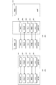
- FIG. 1 is a schematic diagram of a communication system according to each embodiment of the present invention.
- FIG. 3 is a protocol stack diagram of UP and CP of a terminal device and a base station device in E-UTRA in each embodiment of the present invention.
- FIG. 3 is a protocol stack diagram of UP and CP of a terminal device and a base station device in NR in each embodiment of the present invention. It is a figure which shows an example of the flow of the procedure for various settings in RRC208 and/or RRC308 in each embodiment of this invention.
- It is a block diagram which shows the structure of the terminal device in each embodiment of this invention.
- It is a block diagram which shows the structure of the base station apparatus in each embodiment of this invention.
- FIG. 5 is an example of a processing method of the UE 122 according to the first embodiment of the present invention. This is an example in which the release of the E-UTRA secondary cell group in MR-DC is activated from the NR side to the E-UTRA side in the UE 122 in the first embodiment of the present invention.
- the ASN. of the information included in the RRC reconfiguration message indicating that the configuration related to the secondary cell group is released and added simultaneously. 1 is an example of one description.
- 11 is an example of a processing method of the UE 122 according to the third embodiment of the present invention.
- FIG. 16 is another example in which the release of the NR secondary cell group in MR-DC is activated inside the UE 122 in the third embodiment of the present invention.
- LTE (and LTE-A Pro) and NR may be defined as different RATs.
- NR may also be defined as a technology included in LTE.
- LTE may be defined as a technology included in NR.
- LTE that can be connected by NR and Multi RAT Dual connectivity may be distinguished from conventional LTE.
- LTE in which the core network is 5GC may be distinguished from conventional LTE in which the core network is EPC.
- E-UTRA in this embodiment may be replaced with the term LTE, and the term LTE may be replaced with the term E-UTRA.
- FIG. 1 is a schematic diagram of a communication system according to each embodiment of the present invention.
- E-UTRA100 is a radio access technology described in Non-Patent Document 3 and the like, and is composed of a cell group (Cell Group: CG) configured by one or a plurality of frequency bands.
- the eNB (E-UTRAN Node B) 102 is a base station device of the E-UTRA 100.
- EPC (Evolved Packet Core) 104 is a core network described in Non-Patent Document 14 and the like, and was designed as a core network for E-UTRA100.
- the interface 112 is an interface between the eNB 102 and the EPC 104, and includes a control plane (Control Plane: CP) through which a control signal passes and a user plane (User Plane: UP) through which the user data passes.
- Control Plane: CP Control Plane
- User Plane: UP User Plane
- NR106 is a radio access technology described in Non-Patent Document 9 and the like, and is composed of a cell group (Cell Group: CG) configured by one or a plurality of frequency bands.
- the gNB (g Node B) 108 is a base station device of the NR 106.
- the 5GC 110 is a core network described in Non-Patent Document 2 and the like, and is designed as a core network for the NR 106, but may be used as a core network for the E-UTRA 100 having a function of connecting to the 5GC 110.
- the E-UTRA 100 may include the E-UTRA 100 having a function of connecting to the 5GC 110.
- the interface 114 is the interface between the eNB 102 and the 5GC 110
- the interface 116 is the interface between the gNB 108 and the 5GC 110
- the interface 118 is the interface between the gNB 108 and the EPC 104
- the interface 120 is the interface between the eNB 102 and the gNB 108
- the interface 124 is the EPC 104 and the 5GC 110. Is an interface between.
- the interface 114, the interface 116, the interface 118, the interface 120, the interface 124, and the like may be CP-only, UP-only, or interfaces that pass both CP and UP. Further, the interface 114, the interface 116, the interface 118, the interface 120, the interface 124, and the like may not exist depending on the communication system provided by the communication carrier.
- UE122 is a terminal device that supports NR106 or both E-UTRA100 and NR106.
- a radio bearer (RB: Radio Bearer)
- SRB Signaling Radio Bearer
- DRB Data Radio Bearer The radio bearer used for CP is called a signaling radio bearer (SRB: Signaling Radio Bearer), and the radio bearer used for UP is called a data radio bearer (DRB Data Radio Bearer).
- An RB identifier (RB Identity, or RB ID) is assigned to each RB and uniquely identified.
- the RB identifier for SRB is called SRB identifier (SRB Identity, or SRB ID)
- the RB identifier for DRB is called DRB identifier (DRB Identity, or DRB ID).
- each DRB established between the UE 122 and the E-UTRA 100, and/or the NR 106 further passes through the EPC 104. It is uniquely associated with an EPS (Evolved Packet System) bearer.
- An EPS bearer identifier (Identity, or ID) is assigned to each EPS bearer and uniquely identified. Further, the same QoS is guaranteed for the data passing through the same EPS bearer.
- one or more DRBs established between the UE122 and the E-UTRA100 and/or the NR106 are further included in the 5GC110.
- PDU Packet Data Unit
- Each DRB may be associated (map) with one or a plurality of QoS flows existing in the associated PDU session, or may not be associated with any QoS flow.
- Each PDU session is identified by a PDU session identifier (Identity, or ID). Further, each QoS flow is identified by a QoS flow identifier. Further, the same QoS is guaranteed for the data passing through the same QoS flow.
- PDU session and/or QoS flow does not exist in EPC104, and EPS bearer does not exist in 5GC110.
- the UE 122 when the UE 122 is connected to the EPC 104, the UE 122 has information on the EPS bearer, and when the UE 122 is connected to the 5GC 110, the UE 122 has information on the PDU session and/or the QoS flow.
- FIG. 2 is a protocol stack diagram of UP and CP of the terminal device and the base station device in the E-UTRA radio access layer in each embodiment of the present invention.
- FIG. 2A is a protocol stack diagram of the UP used when the UE 122 in the E-UTRA 100 communicates with the eNB 102.
- the PHY (Physical layer) 200 is a wireless physical layer (wireless physical layer) and provides a transmission service to an upper layer (upper layer) using a physical channel (Physical Channel).
- the PHY 200 is connected to a higher-level MAC (Medium Access Control layer) 202, which will be described later, by a transport channel (Transport Channel). Data moves between the MAC 202 and the PHY 200 via the transport channel. Data is transmitted and received between the UE 122 and the PHY of the eNB 102 via a wireless physical channel.
- the MAC 202 is a medium access control layer (medium access control layer) that maps various logical channels (Logical Channels) to various transport channels.
- the MAC 202 is connected to a higher-order RLC (Radio Link Control layer) 204 described later by a logical channel.
- Logical channels are roughly classified according to the type of information to be transmitted, and are classified into a control channel for transmitting control information and a traffic channel for transmitting user information.
- the MAC 202 has a function of controlling the PHY 200 for performing discontinuous transmission (DRX/DTX), a function of executing a random access (Random Access) procedure, a function of notifying transmission power information, a function of performing HARQ control, and the like.
- DRX/DTX discontinuous transmission
- Random Access random access
- the RLC 204 divides the data received from the higher-order PDCP (Packet Data Convergence Protocol Layer) 206 described later, and adjusts the data size so that the lower layer (lower layer) can appropriately transmit the data.
- Wireless link control layer radio link control layer
- the RLC 200 also has a function for guaranteeing the QoS (Quality of Service) required by each data. That is, the RLC 204 has functions such as data retransmission control (Non-Patent Document 6).
- the PDCP 206 is a packet data convergence protocol layer (packet data convergence protocol layer) for efficiently transmitting an IP packet (IP Packet) that is user data in a wireless section.
- the PDCP 206 may have a header compression function that compresses unnecessary control information.
- the PDCP 206 may also have a data encryption function (Non-Patent Document 5).
- the data processed by the MAC 202, RLC 204, and PDCP 206 are called MAC PDU (Protocol Data Unit), RLC PDU, and PDCP PDU, respectively.
- the data passed from the upper layer to the MAC 202, RLC 204, PDCP 206, or the data passed to the upper layer are called MAC SDU (Service Data Unit), RLC SDU, and PDCP SDU, respectively.
- FIG. 2B is a protocol stack diagram of the CP used when the UE 122 in the E-UTRA 100 communicates with the eNB 102 and the MME (Mobility Management Entity) that is a logical node that provides functions such as authentication and mobility management. ..
- MME Mobility Management Entity
- the RRC 208 performs processes such as establishment, re-establishment, suspension (suspend), and suspension release (resume) of RRC connection, and reconfiguration of RRC connection, for example, radio bearer (Radio Bearer: RB) and cell group (Cell Group). Radio link control layer (radio link control) for establishing, changing, releasing, etc., controlling logical channels, transport channels, and physical channels, as well as setting handover and measurement (measurement). Layer).
- the RB may be divided into a signaling radio bearer (Signaling Radio Bearer: SRB) and a data radio bearer (Data Radio Bearer: DRB), and the SRB is used as a route for transmitting an RRC message that is control information. May be.
- the DRB may be used as a route for transmitting user data.
- Each RB may be set between the RRC 208 of the eNB 102 and the UE 122. Further, a part of the RB configured by the RLC 204 and the MAC 202 may be called an RLC bearer (Non-Patent Document 4).
- some or all layers of the PHY 200, the MAC 202, the RLC 204, the PDCP 206, and the RRC 208 that carry the signal between the UE 122 and the eNB 102 may be AS (Access). Strarum) layer.
- the above-mentioned function classification of the MAC 202, RLC 204, PDCP 206, and RRC 208 is an example, and some or all of the functions may not be implemented. Further, some or all of the functions of each layer may be included in another layer.
- the IP layer and the TCP (Transmission Control Protocol) layer, the UDP (User Datagram Protocol) layer, and the application layer above the IP layer are upper layers of the PDCP layer (not shown).
- the RRC layer and the NAS (non Access Stratum) layer are also upper layers of the SDAP layer (not shown).
- the PDCP layer is a lower layer of the RRC layer, the NAS layer, the IP layer, and the TCP (Transmission Control Protocol) layer, the UDP (User Datagram Protocol) layer, and the application layer above the IP layer.
- FIG. 3 is a protocol stack diagram of UP and CP of the terminal device and the base station device in the NR radio access layer in each embodiment of the present invention.
- 3A is a protocol stack diagram of the UP used when the UE 122 communicates with the gNB 108 in the NR 106.
- the PHY (Physical layer) 300 is an NR wireless physical layer (wireless physical layer), and may provide a transmission service to an upper layer using a physical channel (Physical Channel).
- the PHY 300 may be connected to a higher-level MAC (Medium Access Control layer) 302, which will be described later, by a transport channel (Transport Channel). Data may move between the MAC 302 and the PHY 300 via the transport channel. Data may be transmitted and received between the PHY of the UE 122 and the gNB 108 via a wireless physical channel.
- the MAC 302 is a medium access control layer (medium access control layer) that maps various logical channels (Logical Channels) to various transport channels.
- the MAC 302 may be connected to a higher-level RLC (Radio Link Control layer) 304 described later by a logical channel.
- the logical channel is roughly classified according to the type of information to be transmitted, and may be divided into a control channel for transmitting control information and a traffic channel for transmitting user information.
- the MAC 302 has a function of controlling the PHY 300 for performing discontinuous transmission (DRX/DTX), a function of executing a random access (Random Access) procedure, a function of notifying transmission power information, a function of performing HARQ control, and the like. You may have (nonpatent literature 13).
- the RLC 304 divides the data received from a higher-order PDCP (Packet Data Convergence Protocol Layer) 206 described later (Segmentation), and adjusts the data size so that the lower layer can appropriately transmit the data. It is a layer (radio link control layer).
- the RLC 304 may also have a function of guaranteeing the QoS (Quality of Service) required by each data. That is, the RLC 304 may have a function such as data retransmission control (Non-Patent Document 12).
- the PDCP 306 is a packet data convergence protocol layer (packet data convergence protocol layer) that efficiently transmits an IP packet (IP Packet) that is user data in a wireless section.
- the PDCP 306 may have a header compression function that compresses unnecessary control information.
- the PDCP 306 may also have a data encryption function (Non-Patent Document 11).
- the SDAP (Service Data Adaptation Protocol) 310 associates the downlink QoS flow and DRB sent from the 5GC 110 to the terminal device via the base station device (mapping), and the terminal device via the base station device. It is a service data adaptation protocol layer (service data adaptation protocol layer) having a function of performing mapping between an uplink QoS flow sent to the 5GC 110 and a DRB and storing mapping rule information (non-patent document 16).
- service data adaptation protocol layer service data adaptation protocol layer having a function of performing mapping between an uplink QoS flow sent to the 5GC 110 and a DRB and storing mapping rule information (non-patent document 16).
- FIG. 3B is a protocol stack diagram of the CP used when the UE 122 communicates with the gNB 108 and the AMF (Access and Mobility Management function) that is a logical node that provides functions such as authentication and mobility management in the NR 106. ..
- AMF Access and Mobility Management function
- RRC Radio Resource Control layer
- NAS Non Access Stratum
- the RRC 308 performs processing such as establishment, re-establishment, suspension (suspend) and suspension cancellation (resume) of the RRC connection, and reconfiguration of the RRC connection, for example, radio bearer (Radio Bearer: RB) and cell group (Cell Group).
- Radio link control layer radio link control
- Radio link control for establishing, changing, releasing, etc., controlling logical channels, transport channels, and physical channels, as well as setting handover and measurement (measurement). Layer).
- the RB may be divided into a signaling radio bearer (Signaling Radio Bearer: SRB) and a data radio bearer (Data Radio Bearer: DRB), and the SRB is used as a route for transmitting an RRC message that is control information. May be.
- the DRB may be used as a route for transmitting user data.
- Each RB may be set between the gNB 108 and the RRC 308 of the UE 122. Further, a part of the RB that is composed of the RLC 304 and the MAC 302 may be called an RLC bearer (Non-Patent Document 10).
- the NAS layer that carries the signal between the AMF and the UE 122
- some or all layers of the PHY 200, the MAC 202, the RLC 204, the PDCP 206, and the RRC 208 that carry the signal between the UE 122 and the gNB 108 are AS (Access). Strarum) layer.
- MAC 302, RLC 304, PDCP 306, SDAP 310, and RRC 308 is an example, and some or all of the respective functions may not be implemented. Further, some or all of the functions of each layer (each layer) may be included in another layer (layer).
- each layer set in the terminal device and/or (and/or) base station device may be called an entity. That is, the MAC layer, the RLC layer, the PDCP layer, the SDAP layer, and the RRC layer, which are set in the terminal device and/or the base station device, are the MAC entity, the RLC entity, the PDCP entity, the SDAP entity, and the RRC entity. You can call each one.
- the MAC 202, RLC 204, PDCP 206, and RRC 208 are referred to as E-UTRA MAC or LTE MAC and E-UTRA, respectively.
- RLC for LTE or RLC for LTE PDCP for E-UTRA or PDCP for LTE
- RRC for E-UTRA or RRC for LTE.
- the MAC 302, RLC 304, PDCP 306, and RRC 308 may be referred to as an NR MAC, an NR RLC, an NR RLC, and an NR RRC, respectively.
- it may be described using a space such as E-UTRA PDCP or LTE PDCP, NR PDCP.
- the eNB 102, gNB 108, EPC 104, and 5GC 110 may be connected via the interface 112, the interface 116, the interface 118, the interface 120, and the interface 114. Therefore, the RRC 208 of FIG. 2 may be replaced with the RRC 308 of FIG. 3 to support various communication systems.
- the PDCP 206 of FIG. 2 may be replaced with the PDCP 306 of FIG.
- the RRC 308 of FIG. 3 may include the function of the RRC 208 of FIG.
- the PDCP 306 of FIG. 3 may be the PDCP 206 of FIG.
- the NR PDCP may be used as the PDCP even when the UE 122 communicates with the eNB 102.
- SRB0 to SRB3 may be defined in SRB.
- SRB0 may be an SRB for an RRC message using CCCH (Common Control Channel) of a logical channel.
- SRB1 may be the SRB for RRC messages (which may include piggybacked NAS messages) and for NAS messages before SRB2 establishment, all used by the DCCH (Dedicated Control CHannel) of the logical channel. You may be taken.
- SRB2 may be an SRB for NAS message, and DCCH of all logical channels may be used. Also, SRB2 may have a lower priority than SRB1.
- the SRB 3 may be an SRB for a specific RRC message when the UE 122 is set to EN-DC, NGEN-DC, NR-DC, etc., and all logical channel DCCHs may be used. Also, other SRBs may be prepared for other applications.
- the UE 122 may be in the RRC_CONNECTED state when an RRC connection is established (RRC connection has been established). Also, the UE 122 may be in the RRC_INACTIVE state (if the UE 122 is connected to 5GC) when the RRC connection is dormant. If not in those cases, the UE 122 may be in the RRC_IDLE state.
- the UE 122 connected to the EPC does not have the RRC_INACTIVE state, but the suspension of the RRC connection may be started by the E-UTRAN.
- the UE 122 transits to the RRC_IDLE state while holding the AS context of the UE and the identifier (resumeIdentity) used for the return.
- RRC paused when UE 122 holds the AS context of the UE RRC connection reversion is allowed by E-UTRAN, and UE 122 needs to transition from RRC_IDLE state to RRC_CONNECTED state.
- the resumption of connection may be initiated by higher layers (eg NAS layer).
- the definition of sleep may be different between the UE 122 connected to the EPC and the UE 122 connected to the 5GC.
- the UE 122 when it is connected to the EPC (when it is in the RRC_IDLE state and is suspended) and when it is connected to the 5GC (when it is in the RRC_INACTIVE state and is in the suspended state), all of the procedures for returning from the sleep state or Some may be different.
- the AS context of the UE held by the UE 122 is the current RRC setting, the current security context, the PDCP state including the ROHC (RObust Header Compression) state, the C-RNTI used in the PCell of the connection source (Source), and the cell identifier.
- the information may include all or part of (cellIdentity) and the physical cell identifier of the connection source PCell.
- the AS context of the UE held by the eNB 102 and/or the gNB 108 may include the same information as the AS context of the UE held by the UE 122, or information different from the information included in the AS context of the UE held by the UE 122 may be included. May be included.
- the security context is the encryption key at the AS level, the NH (Next Hop parameter), the NCC (Next Hop Chaining Counter parameter) used to derive the access key of the next hop, the identifier of the selected AS level encryption algorithm, and the replay protection.
- the information may include all or some of the counters used for.
- FIG. 4 is a diagram showing an example of a flow of a procedure (procedure) for various settings in the RRC 208 and/or (and/or) RRC 308 according to each embodiment of the present invention.
- 4A is an example of a flow when an RRC message is sent from the base station device (eNB 102 and/or gNB 108) to the terminal device (UE 122), and
- FIG. 4B is from the terminal device (UE 122) to the base station. It is an example of a flow when an RRC message is sent to a station device (eNB 102 and/or gNB 108).
- the base station device creates an RRC message (step S400).
- the creation of the RRC message in the base station device may be performed when the base station device distributes the broadcast information (SI: System Information) or the paging information, or the base station device processes the specific terminal device.
- SI System Information
- the base station device processes the specific terminal device.
- security-related settings for example, security-related settings, RRC connection reconfiguration (radio line bearer processing (establishment, change, release, etc.), cell group processing (establishment, addition, change, release, etc.) ), measurement (measurement) setting, handover setting, etc.), RRC connection state release, and the like.
- the RRC message includes parameters for notification of various information and setting.
- these parameters are referred to as fields and/or information elements, and ASN. It is described using the description method of 1 (Abstract Syntax Notation One).
- the base station device next transmits the created RRC message to the terminal device (step S402).
- the terminal device performs a process, such as a setting process, according to the received RRC message (step S404).
- the terminal device creates an RRC message (step S406).
- the RRC message is created by the terminal device when the request for the base station device is made, for example, the establishment of the RRC connection by a request from the upper layer or the like, the RRC connection by the detection of the radio link failure, the random access failure, or the radio synchronization loss. It may be performed at the time of re-establishment, a request from an upper layer or a release (resume) of the RRC connection temporary suspension (suspend) due to a paging response of a radio access network (RAN), or the above step S402 base It may be performed to respond to the RRC message received from the station device, or may be performed at any other time.
- the “RRC connection temporary suspension” is also referred to as the “RRC connection suspension”.
- release of RRC connection temporary suspension is also referred to as “return of RRC connection (from hibernation state)”.
- the terminal device next transmits the created RRC message to the base station device (step S408).
- the base station device performs the process according to the received RRC message, if the process is necessary (step S410).
- RRC message is not limited to the above example, and may be created for other purposes as described in Non-Patent Document 4, Patent Document 10, and the like.
- the RRC message may be used for the settings regarding Dual Connectivity (DC) and Multi-Radio Dual Connectivity (MR-DC) described in Non-Patent Document 8.
- DC Dual Connectivity
- MR-DC Multi-Radio Dual Connectivity
- the Dual Connectivity is a cell group formed by two base station devices (nodes), that is, a master cell group (Master Cell Group: MCG) and a secondary node (Secondary Node) formed by a master node (Master Node: MN).
- a technology for performing data communication by using both radio resources of a secondary cell group (Secondary Cell Group: SCG) configured by a Node: SN) may be used.
- the MR-DC described in Non-Patent Document 8 is a cell group of RATs (Radio Access Technology) of both E-UTRA and NR that are assigned to UEs by grouping them into cell groups for each RAT, and radio resources of both MCG and SCG.
- RATs Radio Access Technology
- the master node is a main RRC function related to the MR-DC, for example, functions such as addition of secondary node, establishment, change and release of RB, addition, change, release and handover of MCG.
- the secondary node may be a base station having some RRC functions, for example, change and release of SCG.
- the RRC of the RAT on the master node side may be used to set both MCG and SCG.
- the core network is the EPC 104 and the master node is the eNB 102 (also referred to as the extended eNB 102)
- the MR-DC is EN-DC (E-UTRA-NR Dual Connectivity)
- the core network is 5GC110
- the master node is the master node.
- NGEN-DC NG-RAN E-UTRA-NR Dual Connectivity
- the RRC message of the E-UTRA described in Non-Patent Document 4 is transmitted and received between the eNB 102 and the UE 122.
- the RRC message may include not only LTE (E-UTRA) setting information but also NR setting information described in Non-Patent Document 10.
- the RRC message transmitted from the eNB 102 to the UE 122 may be transmitted from the eNB 102 to the UE 122 via the gNB 108.
- the configuration of this RRC message is non-MR-DC, and is used for E-UTRA/5GC (option 5 described in Non-Patent Document 17) in which the eNB 102 (extended eNB) uses 5GC as a core network. May be.
- EN-DC may include NGEN-DC.
- the RRC message of NR described in Non-Patent Document 10 may be transmitted and received between the gNB 108 and the UE 122.
- the RRC message may include not only NR setting information but also LTE (E-UTRA) setting information described in Non-Patent Document 4.
- the RRC message transmitted from the gNB 108 to the UE 122 may be transmitted from the gNB 108 to the UE 122 via the eNB 102.
- NR-DC NR Dual Connectivity
- the NR RRC message described in Non-Patent Document 10 is gNB108. It may be transmitted/received to/from the UE 122. Further, the RRC message transmitted from the gNB 108 to the UE 122 may be transmitted from the gNB 108 to the UE 122 via another gNB 108.
- NR-DC may be expressed as NN-DC, N2-DC, NR2-DC, NRNR-DC, or the like.
- FIG. 5 is a block diagram showing the configuration of the terminal device (UE 122) in each embodiment of the present invention. Note that FIG. 5 illustrates only main components which are closely related to one embodiment of the present invention in order to avoid complexity of description.
- the UE 122 illustrated in FIG. 5 includes a receiving unit 500 that receives an RRC message or the like from the eNB 102 and/or the gNB 108, and various information elements (IE: Information Element) and/or various fields and/or various fields included in the received message.
- the processing unit 502 performs processing according to setting information such as conditions. Further, the processing unit 502 may perform a process of activating a request or instruction from the MCG side to the SCG side within the UE 122 in which DC is set.
- Non-Patent Document 8 EN-DC described in Non-Patent Document 8 or NGEN-DC from the E-UTRA side to the NR side, or, for example, NE-described in Non-Patent Document 8
- processing for activating a request or instruction from the NR side to the E-UTRA side may be performed.
- the processing unit 502 may perform the processing started from the MCG side on the SCG side inside the UE 122 in which DC is set.
- a process started from the E-UTRA side on the NR side or in NE-DC described in Non-Patent Document 8 on the E-UTRA side, for example. You may perform the process started from the NR side.
- setting the MR-DC may be said to be processing the MR-DC, or may be operating the MR-DC.
- the NR side and the E-UTRA side may be NR RRC and E-UTRA RRC, respectively.
- FIG. 6 is a block diagram showing the configuration of the base station device (eNB 102 and/or gNB 108) in each embodiment of the present invention. Note that in order to avoid complexity of description, FIG. 6 illustrates only main components which are closely related to one embodiment of the present invention.
- the eNB 102 and/or gNB 108 illustrated in FIG. 6 includes a transmission unit 600 that transmits an RRC message or the like to the UE 122, and various information elements (IE: Information Element), and/or various fields, and/or setting information such as various conditions. It includes a processing unit 602 that causes the processing unit 502 of the UE 122 to perform a process by creating an RRC message including the above and transmitting it to the UE 122.
- IE Information Element
- Embodiment 1 of the present invention will be described.
- description will be made assuming an MR-DC in which the MCG side is NR and the SCG side is NR, but the present invention is not limited to this and may be applied to other MR-DC. Note that each embodiment of the present invention may be implemented in combination with one or more other embodiments.
- the gNB 108 uses the RRC reconfiguration (RRCReconfiguration) message of RRC signaling (radio resource control signal) to the UE 122 (includes in the RRC reconfiguration message) to measure (measurement) configuration information element (measurement). (Also referred to as setting) is transmitted.
- the UE 122 performs measurement, event evaluation, and measurement report on the serving cell and the adjacent cells (including the list cell (listed cell) and/or the detected cell (detected cell)) according to the information included in the notified measurement setting.
- the list cell is a cell listed as a measurement target (Measurement object) (a cell notified from the gNB 108 to the UE 122 as a neighboring cell list).
- the detection cell is a cell that is detected by the UE 122 in the frequency and subcarrier interval designated by the measurement object (Measurement object) but is not listed in the measurement object (Measurement object) (the UE 122 itself not notified as a neighbor cell list is Detected cells).
- the UE 122 may have a variable VarMeasConfig to hold the notified measurement settings. Also, the UE 122 may have a variable VarMeasReportList in order to hold the measurement information that matches the reporting conditions. In the MR-DC, the UE 122 matches the variable VarMeasConfig for holding the first measurement setting set by (or to or associated with the MCG) and the reporting condition of the first measurement setting. The variable VarMeasReportList for holding the measured information and the variable VarMeasConfig and the second measurement setting for holding the second measurement setting set by the SCG (or to the SCG or in association with the SCG). The variable VarMeasReportList for holding the measurement information that matches the reporting condition of 1.
- the UE 122 controls the timer controlled by the measurement setting set by the MCG (or the MCG or associated with the MCG) (for example, the measurement information based on the measurement setting set by the MCG). Controlled by the SCG (or to the SCG or in association with the SCG) and the timer used to periodically report the timer, the timer T321 used to measure the global identifier, etc. Timer (for example, a timer used to periodically report the measurement information based on the measurement settings set by the SCG or a timer T321 used to measure the global identifier). Good. At this time, the timer names used for the same purpose in the MCG and the SCG may be the same name or different names.
- the variable VarMeasConfig may be provided for each SCG or may be provided for all SCGs.
- the measurement setting notified from the gNB 108 may be notified separately in the MCG measurement setting and the SCG measurement setting.
- (A) a measurement setting for MCG is included in the first RRC reconfiguration message, and the field indicating the information about the SCG of MR-DC included in the first RRC reconfiguration message contains the encapsulated SCG.
- An RRC reconfiguration message (second RRC reconfiguration message) may be included, and the measurement configuration for the SCG may be included in the second RRC reconfiguration message.
- the first RRC reconfiguration message notifying the MCG measurement setting and the first RRC reconfiguration message notifying the SCG measurement setting may be the same RRC reconfiguration message or at different timings. It may be a different RRC reconfiguration message that is notified.
- (B) MCG measurement settings may be notified by SRB1, and SCG measurement settings may be notified by SRB3. Further, either or both of (A) and (B) may be considered in distinguishing between the MCG measurement setting and the SCG measurement setting. Alternatively, the MCG measurement setting and the SCG measurement setting may be distinguished based on other information.
- Intra-frequency measurement is measurements at the downlink frequency of the serving cell (downlink frequency).
- the inter-frequency measurements are measurements at frequencies different from the downlink frequency of the serving cell.
- the inter-radio access technology measurement is a measurement by a radio technology (eg, UTRA, GERAN, CDMA2000, E-UTRA, etc.) different from the radio technology (eg, NR) of the serving cell.
- the measurement settings include a measurement identifier (measId) addition and/or correction list, a measurement identifier deletion list, a measurement object (Measurement objects) addition and/or correction list, a measurement object deletion list, and a report setting (Reporting configurations). And/or modification list, deletion list of report setting, quantity setting (quantityConfig), measurement gap setting (measGapConfig), serving cell quality threshold (s-Measure) setting, or some or all of them may be included.
- quantityConfig quantity setting
- measGapConfig measurement gap setting
- s-Measure serving cell quality threshold
- the quantity setting (quantityConfig) specifies the third layer filter coefficient (L3 filtering coefficient) when the measurement objects (Measurement objects) are NR and/or E-UTRA.
- the third layer filter coefficient (L3 filtering coefficient) defines the ratio (ratio) between the latest measurement result and the past filtering measurement result.
- the filtering result is used by the UE 122 for event evaluation.
- the measurement gap setting (measGapConfig) is used for setting a measurement gap pattern and controlling activation/deactivation of the measurement gap.
- the measurement gap setting may be set independently for each cell, each cell group, each component carrier, each serving cell, or each predetermined frequency range.
- the serving cell quality threshold represents a threshold related to the quality of the serving cell, and is used to control whether or not the UE 122 needs to make a measurement.
- the serving cell quality threshold is set as a value for the reference signal received power (RSRP).
- the measurement identifier (measId) is used to link the measurement object (Measurement objects) and the report settings (Reporting configurations), and specifically, the measurement object identifier (measObjectId) and the report setting identifier (reportConfigId). ) And are linked.
- One measurement object identifier (measObjectId) and one report setting identifier (reportConfigId) are associated with the measurement identifier (measId).
- the measurement setting can be added/corrected/deleted with respect to the relationship among the measurement identifier (measId), the measurement object (Measurement objects), and the report setting (Reporting configurations).
- the measurement identifier deletion list included in the measurement configuration includes the measurement identifier list, and the UE 122 performs the following processes (A) to (C) for each measurement identifier included in the measurement identifier deletion list. I do.
- A) The entry of this measurement identifier is deleted from the variable VarMeasConfig of the cell group that is the target of measurement setting.
- B) If included, delete the measurement report entry for this measurement identifier from the variable VarMeasReportList of the cell group that is the target of measurement setting.
- C Stop the timer or timer T321 used for periodic reporting for this measurement identifier if the timer has started and reset the relevant information for this measurement identifier.
- the timer T321 is a timer that is started when the measurement setting including the report setting for the purpose of measuring the cell global identifier is received, and the measurement report procedure is started when the timer expires. In addition, this timer is stopped when a report setting deletion list described later includes a report setting identifier for the purpose of measuring a cell global identifier, or when the detected cell does not broadcast SIB1.
- the timer T321 may be an independent timer for MCG and SCG, a common timer, or a timer used only for MCG or SCG. When the timers are independent timers, the UE 122 may determine which timer to use based on the cell group to be measured and set.
- the timer used for reporting the cycle may be an independent timer for MCG and SCG, a common timer, or a timer used only for MCG or SCG.
- the UE 122 may determine which timer to use based on the cell group to be measured and set. For example, depending on the purpose, the UE 122 has a timer used for periodic reporting useful for mobility or secondary cell detection as an independent timer for the MCG and SCG, and mainly measures the cell global identifier used for network optimization.
- the UE T122 may have a timer T321 for use as a timer used only in the MCG. Alternatively, the UE 122 may operate assuming that the measurement settings with the start of the timer T321 are not simultaneously set in both the MCG and the SCG. This can prevent the UE 122 from being complicated in design.
- the measurement identifier addition and/or correction list included in the measurement configuration includes a list of measurement identifiers, and the UE 122 performs the following (for each measurement identifier included in the measurement identifier addition and/or correction list).
- the processing from A) to (C) is performed.
- the measurement target deletion list (measObjectToRemoveList) included in the measurement setting is a field including information that deletes the measurement object (Measurementobjects) corresponding to the specified measurement object identifier (measObjectId) and the specified measurement object identifier (measObjectId). Is. At this time, all the measurement identifiers (measId) of the cell group that is the target of the measurement setting associated with the designated measurement target identifier (measObjectId) may be deleted. In this field, a plurality of measurement object identifiers (measObjectId) can be designated at the same time.
- the addition and/or correction list (measObjectToAddModList) of the measurement target included in the measurement setting is specified by modifying the measurement target (Measurementobjects) specified by the measurement target identifier (measObjectId) or by specifying the measurement target identifier (measObjectId).
- This is a field that contains information to add measurement objects (Measurement objects). In this field, a plurality of measurement object identifiers (measObjectId) can be designated at the same time.
- the deletion list (reportConfigToRemoveList) of the report settings included in the measurement settings includes a field including information that deletes the specified report setting identifier (reportConfigId) and the report settings (Reporting configurations) corresponding to the specified report configuration identifier (reportConfigId). Is. At this time, all the measurement identifiers (measId) associated with the designated report setting identifier (reportConfigId) are deleted. This command can specify a plurality of report setting identifiers (reportConfigId) at the same time.
- the report setting addition and/or modification list modifies the reporting configuration (Reportingconfigurations) specified by the reporting configuration identifier (reportConfigConfigId), or the reporting configuration (Reporfconfig) specified by the reporting configuration identifier (reportConfigConfig). ) Is a field containing information to be added. In this field, multiple report setting identifiers (reportConfigId) can be designated at the same time.
- the measurement identifier deletion list (measIdToRemoveList) is a command for deleting the specified measurement identifier (measId).
- the measurement target identifier (measObjectId)
- the report setting identifier (reportConfigId) associated with the designated measurement identifier (measId) are maintained without being deleted.
- This command can specify a plurality of measurement identifiers (measId) at the same time.
- the measurement identifier addition and/or correction list (measIdToAddModifyList) is modified so that the specified measurement identifier (measId) is associated with the specified measurement target identifier (measObjectId) and the specified report setting identifier (reportConfigId), or
- This command can specify a plurality of measurement identifiers (measId) at the same time.
- the measurement objects are set (specified) for each RAT and frequency.
- the measurement target may be set for each frequency and subcarrier interval.
- the reporting settings may have a definition for NR and a specification for RAT other than NR.
- the measurement object includes a measurement object NR (measObjectNR) whose measurement object associated with the measurement object identifier (measObjectId) is NR, and a measurement object EUTRA (measObjectEUTRA) whose measurement object is E-UTRA.
- the measurement target is a measurement target UTRA (measObjectUTRA) whose measurement target is UTRA, a measurement target GERAN (measObjectGERAN) whose measurement target is GERAN, a measurement target CDMA2000 (measObjectCDMA2000) whose measurement target is CDMA2000, and a measurement target WLAN.
- asObjectWLAN Part or all of the measurement target WLAN (measObjectWLAN) that is
- the measurement object identifier is an identifier used to identify the setting of the measurement object (Measurement objects).
- the setting of measurement objects is defined for each radio access technology (RAT) and frequency, and for NR, for each subcarrier interval.
- the measurement objects (Measurement objects) may be separately specified for E-UTRA, UTRA, GERAN, and CDMA2000.
- a measurement object NR (measObjectNR), which is a measurement object (Measurement objects) for NR, defines information applied to a serving cell and an adjacent cell of NR. It should be noted that which measurement target identifier indicates which measurement target corresponds to the serving cell is indicated by an information element (for example, serving cell configuration) included in the RRC message containing the measurement configuration and/or the RRC message not containing the measurement configuration. You can
- the measurement target NR relates to frequency information (ssbFrequency) of a block (SSB) including a synchronization signal, SSB subcarrier spacing (ssbSubcarrierSpacing), information on a list of cells to be measured, and a blacklist to be excluded from the measurement. Some or all of the information, the information about the white list to be measured, may be included.
- Information on the list of cells to be measured includes information on cells to be subject to event evaluation and measurement reports.
- the information on the list of cells to be measured includes a physical cell identifier (physical cell ID), a cell-specific offset (cellIndividualOffset, which indicates a measurement offset value applied to an adjacent cell), and the like.
- the report setting includes a report setting NR (reportConfigNR) associated with a report setting identifier (reportConfigId).
- the report setting identifier is an identifier used to identify report settings (Reporting configurations) related to measurement.
- the reporting settings for measurement may include a regulation for NR and a regulation for RATs (UTRA, GERAN, CDMA2000, E-UTRA) other than NR.
- a report setting NR (reportConfigNR) that is a report setting (Reporting configurations) for the NR defines a trigger condition (triggering criterion) of an event used for reporting the measurement in the NR.
- the report setting NR includes an event identifier (eventId), a trigger amount (triggerQuantity), a hysteresis (hysteresis), a trigger time (timeToTrigger), a report amount (reportQuantity), a maximum report cell number (maxReportIntervals). (ReportInterval) and the number of reports (reportAmount) may be partially or entirely included.
- the event identifier (eventId) is used to select a condition (criteria) related to an event triggered report (event triggered reporting).
- the event triggered reporting is a method of reporting the measurement when the event trigger condition is satisfied.
- event trigger conditions at least the 6 types described below may be specified.
- the UE 122 makes a measurement report (measurement report) to the gNB 108.
- the trigger amount (triggerQuantity) is an amount used for evaluating an event trigger condition. That is, the reference signal reception power (RSRP) or the reference signal reception quality (RSRQ) is designated. That is, the UE 122 uses the amount specified by the trigger amount (triggerQuantity) to measure the downlink synchronization signal, and determines whether or not the event trigger condition specified by the event identifier (eventId) is satisfied. judge.
- Hysteresis is a parameter used in an event trigger condition.
- the trigger time indicates a period in which the event trigger condition should be satisfied.
- the report amount indicates the amount to be reported in the measurement report (measurement report).
- the amount designated by the trigger amount (triggerQuantity), the reference signal reception power (RSRP) or the reference signal reception quality (RSRQ) is designated.
- the maximum number of reportable cells indicates the maximum number of cells included in the measurement report (measurement report).
- the reporting interval (reportInterval) is used for a periodical report (periodical reporting) or an event-triggered periodical reporting (event triggered periodical reporting), and is periodically reported at intervals indicated by the reporting interval (reportInterval).
- the number of reports defines the number of times a periodical report (periodical reporting) is performed, if necessary.
- threshold parameters and offset parameters (a1_Threshold, a2_Threshold, a3_Offset, a4_Threshold, a5_Threshold1, a5_Threshold1, a5_Thresholdhold2, a6_Offset, c1_threshold, a6_Offset, c1_threshold, a6_Offset, c1_threshold, a5_Threshold1, a5_Threshold1, a5_Threshold1, a5_Threshold, a6_Offset, c1_threshold, and a6_Offset, c1_threshold, and UE 122 may be notified.
- a plurality of event trigger conditions for making a measurement report are defined, each of which has a joining condition and a leaving condition. That is, the UE 122 that satisfies the subscription condition for the event designated by the gNB 108 transmits a measurement report (measurement report) to the gNB 108. In addition, the UE 122 that satisfies the departure condition for the event designated by the gNB 108 is set to trigger the report when the departure condition is satisfied from the gNB 108 (when the report setting includes reportOnLeave), the UE 122 is notified to the gNB 108. A measurement report is transmitted to the device.
- the report setting InterRAT which is the report setting (Reporting configurations) for the RAT other than the NR
- multiple triggering conditions (triggering criteria) of the event used for reporting the measurement in the RAT other than the NR are defined. For example, if the measurement result of the adjacent cell (another RAT) is better than the threshold b1_Threshold set for each RAT after applying each parameter, the event B1 occurs. Moreover, when the measurement result of PCell is worse than the threshold value b2_Threshold 1 after application of each parameter and the measurement result of the adjacent cell (other RAT) is better than the threshold value b2_Threshold 2 set for each RAT after application of each parameter, the event B2 occurs.
- the gNB 108 may or may not notify the serving cell quality threshold (s-Measure).
- the serving cell quality threshold (s-Measure) is set to the UE 122 by the gNB 108, and the quality (RSRP value) after the layer 3 filtering of the PCell which is the serving cell (serving cell) is lower than the serving cell quality threshold (s-Measure).
- the adjacent cell of the frequency and RAT designated by the measurement target is measured.
- the serving cell quality threshold (s-Measure) is not set in the UE 122 by the gNB 108, the UE 122 measures the neighboring cell regardless of the quality (RSRP value) of the serving cell.
- the UE 122 starts the measurement report procedure when the event trigger condition is satisfied, the first measurement result of the period report becomes available (Available), or the period report timer or the timer T321 expires. You may.
- the purpose of the measurement report procedure is to transfer a measurement report from the UE 122 to the network.
- the measurement report includes the measurement result.
- a measurement result is set for each measurement identifier for which the measurement reporting procedure was triggered.
- the measurement result may include a measurement identifier (measId), a list of serving measurement target measurement results (measResultServingMO), and an adjacent cell measurement result (measResultNeighCellNR).
- the adjacent cell measurement result may include either the NR measurement result list or the E-UTRA measurement result list.
- the NR measurement result and the E-UTRA measurement result include part or all of the information of the physical cell identifier, the cell measurement result, and the cell global identifier.
- the serving measurement target measurement result (measResultServingMO) is the measurement result of the measurement target associated with the serving cell, and may include a part or all of the serving cell identifier, the serving cell measurement result, and the best neighbor cell measurement result. ..
- the measurement result as described above is set for each measurement identifier for which the measurement report procedure was triggered, and if UE 122 is set to EN-DC, SRB3 is set. If so, the measurement report message including the measurement result is sent to the lower layer through SRB3 for transmission, and the procedure is terminated. If SRB3 is not set, the measurement report message is entered in the RRC message of E-UTRA. It is encapsulated (embedded) and submitted to the lower layer through the E-UTRA MCG. If the UE 122 is set to NR-DC and the measurement setting that triggered this measurement report is associated with SCG (Associated), the measurement including the measurement result through SRB3 for transmission if SRB3 is set.
- the report message is submitted to the lower layer and the procedure is terminated. If SRB3 is not set, the measurement report message is encapsulated (embedded) in the RRC message of the NR MCG, and the lower layer is passed through the MCG of the NR. Submit to.
- UE 122 can perform appropriate measurement for each cell group by setting the measurement in consideration of the cell group that is the target of measurement setting.
- NE-DC which is MR-DC in which the MCG side is the NR and the SCG side is the E-UTRA
- another MR-DC or the same RAT E-UTRA, NR, etc. may be applied to DC having MCG and SCG.
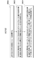
- the processing unit 502 of the UE 122 determines whether the release of the E-UTRA secondary cell group (Secondary Cell Group: SCG) in the MR-DC has been activated from the MCG side to the E-UTRA side, which is the SCG side, inside the UE 122. It is determined whether or not (step S700).
- the MR-DC in step S700 may be NE-DC.
- the release of the E-UTRA secondary cell group in MR-DC may be called the release of NE-DC.
- the E-UTRA secondary cell group may be simply referred to as a secondary cell group.
- MCG may be NR.
- the processing unit 502 of the UE 122 inside the UE 122, releases the E-UTRA secondary cell group in the MR-DC from the MCG side to the E-UTRA side, and then the E-in the MR-DC is activated.
- the RLC entity is released for each RLC bearer set in the UTRA secondary cell group.
- the release of the RLC entity described above may be performed after the re-establishment of the RLC entity (step S702).
- the above-mentioned "for each RLC bearer" may be rephrased as "for each logical channel or each logical channel identifier", or may be added.
- MCG may be NR.
- the processing unit 502 of the UE 122 is based on the fact that the release of the E-UTRA secondary cell group in the MR-DC is activated from the MCG side to the E-UTRA side inside the UE 122, in addition to the processing in step S702 described above. , E-UTRA release of measurement setting set in the secondary cell group, and/or release of MAC of secondary cell group if MAC of secondary cell group exists, and/or release of secondary cell group, and/or Alternatively, the timer for determining the failure of the radio link of the secondary cell group may be stopped, and/or the timer for determining the failure of the change of the secondary cell group may be stopped (step S704). Further, MCG may be NR.
- the activation of the release of the E-UTRA secondary cell group in the MR-DC from the MCG side to the E-UTRA side in the UE 122 is performed by, for example, re-establishing the RRC connection (RRC Re-establishment) in the NR side.
- RRC Re-establishment RRC Re-establishment
- the above-mentioned “determine whether MR-DC is set” may be referred to as “determine whether NE-DC is set”. Further, the above-mentioned “may be activated based on setting MR-DC” may be referred to as “may be activated based on setting NE-DC”. ..
- the activation of the release of the E-UTRA secondary cell group in the MR-DC from the MCG side to the E-UTRA side in the UE 122 described above is performed, for example, in the NR side, by releasing (resume) the RRC connection temporary suspension (suspend). May be activated based on the fact that the MR-DC has been set when the RRC connection is temporarily suspended, and the MR-DC has been set (not shown).
- setting the MR-DC may be said to be processing the MR-DC or may be operating the MR-DC.
- the above-mentioned “determine whether MR-DC has been set” may be referred to as “determine whether NE-DC has been set”.
- the above-mentioned “may be activated based on setting of MR-DC” may be said to be “may be activated based on setting of NE-DC”.
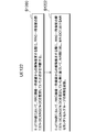
- FIG. 8 shows an example in which the release of the E-UTRA secondary cell group in MR-DC is activated from the NR side to the E-UTRA side in the above-mentioned UE 122 in Embodiment 2 of the present invention.
- the processing unit 602 of the gNB 108 creates an RRC reconfiguration message, which is an RRC message for causing the UE 122 to perform the RRC connection reconfiguration process, and transmits it from the transmission unit 600 to the UE 122 (not shown).
- the receiving unit 500 of the UE 122 receives the RRC reconfiguration message from the gNB 108 (step S800). Note that the UE 122 may receive the RRC reconfiguration message from the eNB 102.
- the processing unit 502 of the UE 122 determines whether or not the RRC reconfiguration message received in step S800 includes information indicating that the release and addition of the E-UTRA SCG configuration are performed at the same time (Ste S804). It should be noted that the above-mentioned “determining whether or not the information indicating that the setting and the addition of the E-UTRA SCG settings are simultaneously performed is included” means that the setting and the addition of the E-UTRA SCG settings are released and added. In other words, it is determined whether the information indicating that they are performed at the same time is true or false.” Further, the above true/false may be replaced with another description having contradictory meaning such as enable/disable, on/off, 1/0.
- the above-mentioned “release and addition of settings regarding E-UTRA SCG is performed at the same time” may be rephrased as “release and addition of all settings regarding E-UTRA SCG are performed at the same time”.
- the above-mentioned “setting regarding E-UTRA SCG” and “all setting regarding E-UTRA SCG” may be those set by E-UTRA, or set by the RRC message of E-UTRA. It may be one.
- the processing unit 502 of the UE 122 determines that the above-mentioned RRC reconfiguration message includes information indicating that the configuration related to the secondary cell group of E-UTRA is released and added at the same time.
- the release of the E-UTRA secondary cell group in the MR-DC is started (step S804).
- the MR-DC in step S804 may be NE-DC.
- the above-mentioned “based on the fact that the information indicating that the setting and the addition of the E-UTRA SCG are simultaneously released is included” means that the setting and the addition of the E-UTRA SCG setting are released at the same time. It may be paraphrased based on the fact that the information indicating what is to be done is true.
- the above true may be replaced by another expression, such as enable, on, 1 etc., which means that this information is valid.
- the above-mentioned ""information indicating that setting and release of SCG related to E-UTRA is released at the same time" may be included when full setting is required on the E-UTRA SCG side, or true ( true), enable, on, 1, etc., may mean that this information is valid.
- the example of the processing shown in FIG. 8 may be used not only for releasing the E-UTRA secondary cell group in MR-DC but also for releasing the NR secondary cell group in NR-DC.
- the above-mentioned “setting relating to SCG of E-UTRA” may be restated as “setting relating to SCG of NR”.
- FIG. 9 shows the ASN. of the information indicating that the configuration related to the secondary cell group contained in the RRC reconfiguration message in FIG. 8 in the second embodiment of the present invention is released and added at the same time.
- the description RRCReconfiguration-IEs indicating the information element of the RRC reconfiguration message includes Radio Bearer Config, which is an information element indicating the setting of the radio bearer, and information indicating the setting information of the radio bearer.
- the element includes a field of information indicating that the above-mentioned setting related to the secondary cell group is released and added at the same time, that is, needc-ReleaseAndAdd-r15.
- the name of the information element or field indicating each piece of information does not have to be this name.
- the processing based on the fact that the release of the E-UTRA secondary cell group in the MR-DC is activated from the MCG side to the E-UTRA side is performed by the NE- It may be called DC release, E-UTRA MR-DC release, or MR-DC E-UTRA SCG release. Or you may call it by another name.
- Embodiment 2 of the present invention based on the fact that the release of the E-UTRA secondary cell group in MR-DC is activated from the NR side which is the MCG to the E-UTRA side in the UE 122. , E-UTRA secondary cell group release processing can be performed. That is, the terminal device can reduce the complexity of the MR-DC protocol processing and can efficiently perform communication.
- the MCG side is E-UTRA and the SCG side is NR MR-DC, EN-DC and/or NGEN-DC, and/or both MCG side and SCG side are NR.
- description will be made assuming a certain NR-DC, it may be applied to another MR-DC or a DC having another same RAT in MCG and SCG.
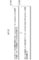
- the processing unit 502 of the UE 122 is an NR secondary cell in MR-DC and/or NR-DC (DC in which NR is RAT in both MCG and SCG) from the MCG side to the NR side that is the SCG side. It is determined whether or not the release of the group (Secondary Cell Group: SCG) is activated (step S1000).
- the MR-DC in step S1000 may be EN-DC and/or NGEN-DC and/or NR-DC.
- the NR secondary cell group may be simply referred to as a secondary cell group.
- the MCG may be E-UTRA or NR.
- step S1000 it may be determined whether the release of the MR-DC is activated, not whether the release of the NR secondary cell group (Secondary Cell Group: SCG) is activated.
- the release of the NR secondary cell group may be executed (activated) in the procedure of releasing the MR-DC.
- the release of EN-DC and the release of MR-DC may be distinguished. That is, the release of the NR secondary cell group in the EN-DC triggers the release of the EN-DC, and the NR secondary in the MR-DC (DC including at least NE-DC and/or NR-DC but not EN-DC) Release of the cell group may trigger release of the MR-DC.
- release of MR-DC may be further subdivided into release of NE-DC, release of NR-DC, and the like.
- the RLC entity is released for each RLC bearer set in the NR secondary cell group. (Step S1002).
- the above-mentioned "for each RLC bearer" may be rephrased as "for each logical channel or each logical channel identifier", or may be added.
- the MCG may be E-UTRA or NR.
- the processing unit 502 of the UE 122 determines that the release of the NR secondary cell group in the MR-DC and/or the NR-DC has been activated from the MCG side to the NR side inside the UE 122.
- the processing unit 502 of the UE 122 determines that the release of the NR secondary cell group in the MR-DC and/or the NR-DC has been activated from the MCG side to the NR side inside the UE 122.
- the processing unit 502 of the UE 122 determines that the release of the NR secondary cell group in the MR-DC and/or the NR-DC has been activated from the MCG side to the NR side inside the UE 122.
- the processing unit 502 of the UE 122 determines that the release of the NR secondary cell group in the MR-DC and/or the NR-DC has been activated from the MCG side to the NR side inside the UE 122.
- the timer for judging failure in changing the secondary cell group may
- the measurement setting released here may be the measurement setting set by the RRC of the NR, the measurement setting for the SCG, or the measurement setting associated with the SCG.
- the measurement setting may be the measurement setting set by the SCG, the measurement setting may be set by the RRC message for setting the secondary cell group, or the NR included in the RRC message of the E-UTRA may be set.
- the measurement setting may be set by the NR RRC message (for example, RRC reconfiguration message) included in the information element (nr-SecondaryCellGroupConfig-r15) that sets the secondary cell group.
- the MR-DC release process and the secondary cell group release process may be separate processes. For example, when MCG is NR and the release of MR-DC is triggered, the UE 122 releases SRB3 if SRB3 is present, and if UE122 is configured with a secondary cell group of NR, a specific measurement is performed. If the UE 122 is not configured with the NR secondary cell group (that is, if the UE 122 is configured with the E-UTRA secondary cell group), the configuration is released and the secondary cell group is released.
- the NE-DC release or the release of the setting related to the SCG shown in the form 2 may be activated.
- the specific measurement setting may be a measurement setting for the SCG, a measurement setting associated with the SCG, or a measurement setting set by the SCG, It may be the measurement setting set by the RRC message for setting the secondary cell group, or the measurement setting set by the RRC message (for example, RRC reconfiguration message) included in the nr-SCG.
- the process of releasing the secondary cell group is (A) resetting the SCG MAC if the SCG MAC is set, and (B) releasing the RLC bearer for each RLC bearer that is part of the SCG setting. (C) release SCG setting, (D) stop timer for judging SCG radio link failure, and (E) stop timer for judging SCG change failure. It may include some or all of the processing.
- FIG. 11 is a diagram showing an example in which the release of the NR secondary cell group in MR-DC is activated from the E-UTRA side to the NR side in the UE 122 according to the third embodiment of the present invention.
- the processing unit 502 of the UE 122 determines whether or not MR-DC is set when requesting re-establishment of RRC connection (RRC Connection Re-establishment) (step S1100).
- Release of the NR secondary cell group in MR-DC may be activated based on the setting of -DC (step S1102).
- setting the MR-DC may be said to be processing the MR-DC, or may be operating the MR-DC.
- the above-mentioned “determine whether MR-DC is set” may be referred to as “determine whether EN-DC or NGEN-DC is set”.
- the above-mentioned “release of the NR secondary cell group in MR-DC may be activated based on the setting of MR-DC.” “EN-DC or NGEN-DC is set. Based on the above, the release of the NR secondary cell group in the MR-DC may be activated.” or “Based on the fact that EN-DC or NGEN-DC is set, The release of DC (or the release of MR-DC) may be activated.”
- FIG. 12 is a diagram showing another example in which the release of the NR secondary cell group in the MR-DC is activated from the E-UTRA side to the NR side inside the UE 122 according to the third embodiment of the present invention.
- the processing unit 502 of the UE 122 determines whether or not the MR-DC is set when the RRC connection is temporarily held when the E-UTRA side requests release (resume) of the RRC connection temporary hold (suspend) (Ste S1200), the release of the NR secondary cell group in MR-DC may be activated based on the fact that MR-DC has been set (step S1202).
- the above-mentioned “determine whether MR-DC has been set” may be referred to as “determine whether EN-DC or NGEN-DC has been set”.
- release of the NR secondary cell group in MR-DC may be activated based on the fact that MR-DC has been set.” means that EN-DC or NGEN-DC has been set. Based on the setting of EN-DC or NGEN-DC, the release of the NR secondary cell group in the MR-DC may be activated.” Release (or release of MR-DC) may be activated.”
- the activation of releasing the NR secondary cell group in the MR-DC and/or the NR-DC from the MCG side to the NR side inside the UE 122 may be activated based on another event.
- the E-UTRA may be activated by receiving an RRC connection reconfiguration message including information indicating that release and addition of all configurations related to the secondary cell group of NR are performed at the same time. It should be noted that the above-mentioned “based on the fact that the information indicating that all the settings related to the NR secondary cell group are released and added at the same time” is “release of all the settings related to the NR secondary cell group”. Can be paraphrased based on the fact that the information indicating that the addition and the addition are performed at the same time is true.
- FIG. 13 is a diagram showing an example in which the release of the NR secondary cell group in the MR-DC is activated inside the UE 122 according to the third embodiment of the present invention.
- the processing unit 502 of the UE 122 determines whether or not MR-DC is set when requesting re-establishment of RRC connection (RRC Connection Re-establishment) in the NR (step S1300), and sets MR-DC to MR-DC.
- the release of the secondary cell group in the MR-DC may be activated based on the setting (step S1302). It should be noted that setting the MR-DC may be said to be processing the MR-DC, or may be operating the MR-DC. Further, in step S1302, the release of the secondary cell group may not be activated, but the release of the MR-DC may be executed (activated).
- FIG. 14 shows another example in which the release of the secondary cell group in the MR-DC is activated inside the UE 122 according to the third embodiment of the present invention.
- the processing unit 502 of the UE 122 determines whether or not the MR-DC is set at the time of the RRC connection temporary suspension (step S1400), and the MR-
- the release of the NR secondary cell group in DC may be activated based on the fact that MR-DC has been set (step S1402). It should be noted that setting the MR-DC may be said to be processing the MR-DC, or may be operating the MR-DC. Further, in step S1302, the release of the secondary cell group may not be activated, but the release of the MR-DC may be executed (activated).
- the activation of releasing the NR secondary cell group in the MR-DC and/or the NR-DC from the MCG side to the NR side inside the UE 122 may be activated based on another event.
- the E-UTRA may be activated by receiving an RRC connection reconfiguration message including information indicating that release and addition of all configurations related to the secondary cell group of NR are performed at the same time. It should be noted that the above-mentioned “based on the fact that the information indicating that all the settings related to the NR secondary cell group are released and added at the same time” is “release of all the settings related to the NR secondary cell group”. Can be paraphrased based on the fact that the information indicating that the addition and the addition are performed at the same time is true.
- EN-DC release may be referred to as NGEN-DC release, and may be referred to as EN-DC or NGEN-DC release.
- NR MR-DC release may also be called NR MR-DC release, MR-DC NR SCG release, NR SCG release, SCG release, or the like. Or you may call it by another name.
- the terminal device can reduce the complexity of the MR-DC protocol processing and can efficiently perform communication.
- the secondary cell group designated by the RRC message is released depending on the conditions. It may be activated, or release of the secondary cell group may be activated for all the secondary cell groups. For example, when the release of the secondary cell group is instructed by the RRC connection reconfiguration message of E-UTRA and the RRC reconfiguration message of NR, the release of one or more designated secondary cell groups may be activated. .. Further, in the process of resuming the RRC connection (Resume) and re-establishing the RRC connection (RRC Connection Re-establishment), release of all the secondary cell groups may be activated.
- the release of NE-DC is activated for the secondary cell group of E-UTRA and the secondary of NR is activated.
- the release of MR-DC may be triggered for the cell group.
- Embodiment 4 A fourth embodiment of the present invention will be described.
- description will be made assuming an MR-DC in which NR is on the MCG side and NR is on the SCG side, but the present invention is not limited to this and may be applied to other MR-DC.
- the RRC message (eg, RRC reconfiguration message) received from the gNB 108 includes a cell group setting (CellGroupConfig), and an information element (sCellToAddModList) that instructs addition and/or correction of a secondary cell to the cell group setting. If included, secondary cell addition and/or modification procedures may be performed. Further, sCellToAddModList includes one or more secondary cell configuration information elements, and each secondary cell configuration information element has an identifier (index) for identifying the secondary cell and the configuration of the serving cell corresponding to the identifier. Information may be included.
- the UE 122 includes a part of the following (A) to (C) for each of the secondary cell identifiers (indexes) included in the sCellToAddModList that are not currently set in the UE 122. Alternatively, all the processing is performed.
- a secondary cell is added to the cell group that is the target of sCellToAddModList based on the setting information of the serving cell corresponding to the index of the secondary cell.
- B The lower layer is set so that the state of the secondary cell becomes an inactive state (Deactivated state).
- the UE 122 modifies the secondary cell having that identifier based on the setting information of the serving cell corresponding to that identifier.
- the measurement setting can be appropriately set according to the embodiment of the present invention. Further, by activating the release of the MR-DC instead of deleting (releasing) the PSCell and the secondary cell, it becomes possible to centrally manage the processing relating to measurement setting under various conditions.
- the UE 122 terminal device
- the gNB 108 and/or the eNB base station device
- a first aspect of the present invention is a terminal device, and based on activation of release of MR-DC, if an NR secondary cell group is set in MR-DC, at least the above-mentioned It has a processing unit that releases the measurement setting set for the secondary cell group and activates the release of the NE-DC if the NR secondary cell group is not set.
- the terminal device when the terminal device further sets the MR-DC based on the fact that the re-establishment of the RRC connection is activated and/or the restoration of the RRC connection is activated. Trigger the release of MR-DC.
- a second aspect of the present invention is a base station apparatus, which notifies the terminal device of the release of MR-DC to the terminal device in which an NR secondary cell group is set in MR-DC, At least the measurement setting set for the secondary cell group is released, and the terminal device for which the NR secondary cell group is not set has a processing unit for activating the release of the NE-DC.
- a third aspect of the present invention is a method applied to a terminal device, wherein an NR secondary cell group is set in MR-DC based on activation of MR-DC release. Then, at least the step of releasing the measurement setting set for at least the secondary cell group and activating the release of the NE-DC if the NR secondary cell group is not set is included.
- the MR-DC is set when the MR-DC is set based on that the re-establishment of the RRC connection is activated and/or the restoration of the RRC connection is activated. -Including the step of triggering the release of the DC.
- a fourth aspect of the present invention is a method applied to a base station apparatus, wherein an NR secondary cell group is set in MR-DC by notifying the terminal apparatus of the release of MR-DC.
- the method further includes at least causing the terminal device to release the measurement setting set for at least the secondary cell group, and causing the terminal device for which the NR secondary cell group is not set to release the NE-DC.
- a fifth aspect of the present invention is an integrated circuit mounted on a terminal device, wherein an NR secondary cell group is set in MR-DC based on activation of release of MR-DC. If so, at least the measurement setting set for the secondary cell group is released, and if the NR secondary cell group is not set, the terminal device is caused to exhibit the function of activating the release of the NE-DC. ..
- the integrated circuit when the MR-DC is set based on the fact that the re-establishment of the RRC connection is activated and/or the restoration of the RRC connection is activated, -Make the terminal device perform the function of activating the release of DC.
- a sixth aspect of the present invention is an integrated circuit implemented in a base station device, wherein an NR secondary cell group is set in MR-DC by notifying the terminal device of release of MR-DC.
- the base station has a function of causing the terminal device that is present to release at least the measurement setting that is set for the secondary cell group, and causing the terminal device that is not set to the NR secondary cell group to activate the release of the NE-DC. Show it to the device.
- the program operating on the device controls the Central Processing Unit (CPU) and the like so that the computer functions so as to realize the functions of the above-described embodiments according to one aspect of the present invention. It may be a program.
- the program or information handled by the program is temporarily read into a volatile memory such as Random Access Memory (RAM) at the time of processing, or stored in a nonvolatile memory such as a flash memory or a Hard Disk Drive (HDD), as necessary.
- RAM Random Access Memory
- HDD Hard Disk Drive
- the CPU reads, corrects, and writes.
- a part of the device in the above-described embodiment may be realized by a computer.
- the program for realizing this control function is recorded in a computer-readable recording medium, and the program recorded in this recording medium is read by the computer system and executed.
- the "computer system” referred to here is a computer system built in the apparatus, and includes operating systems and hardware such as peripheral devices.
- the "computer-readable recording medium” may be a semiconductor recording medium, an optical recording medium, a magnetic recording medium, or the like.
- a "computer-readable recording medium” means that a program can be held dynamically for a short period of time, such as a communication line for transmitting the program via a network such as the Internet or a communication line such as a telephone line. It may also include a program that holds a program for a certain period of time, such as a volatile memory inside a computer system that serves as a server or a client in that case. Further, the above-mentioned program may be for realizing a part of the above-mentioned functions, and may be one for realizing the above-mentioned functions in combination with a program already recorded in the computer system. ..
- each functional block or various features of the device used in the above-described embodiment may be implemented or executed by an electric circuit, that is, typically an integrated circuit or a plurality of integrated circuits.
- An electrical circuit designed to perform the functions described herein may be a general purpose processor, a digital signal processor (DSP), an application specific integrated circuit (ASIC), a field programmable gate array (FPGA), or others. Programmable logic devices, discrete gate or transistor logic, discrete hardware components, or combinations thereof.
- a general purpose processor may be a microprocessor, or in the alternative, the processor may be any conventional processor, controller, microcontroller, or state machine.
- the general-purpose processor, or each of the circuits described above may be configured by a digital circuit or an analog circuit. Further, in the case where an integrated circuit technology that replaces the current integrated circuit has appeared due to the progress of semiconductor technology, it is possible to use the integrated circuit according to the technology.
- the present invention is not limited to the above embodiment. Although an example of the apparatus is described in the embodiment, the present invention is not limited to this, and a stationary or non-movable electronic device installed indoors or outdoors, for example, an AV device, a kitchen device, It can be applied to terminal devices or communication devices such as cleaning/laundry equipment, air conditioning equipment, office equipment, vending machines, and other household appliances.
Landscapes
- Engineering & Computer Science (AREA)
- Computer Networks & Wireless Communication (AREA)
- Signal Processing (AREA)
- Mobile Radio Communication Systems (AREA)
Abstract
端末装置であって、第1のメッセージを受信する受信部と、前記第1のメッセージに含まれるメジャメント設定に基づき測定を実行する制御部とを備え、前記制御部は、MR-DCの解放が起動された事に基づいて、セカンダリセルグループに関連付けられた前記メジャメント設定を解放する。
Description
本発明は、端末装置、基地局装置、方法、および、集積回路に関する。本願は、2019年2月7日に日本で出願された特願2019-20708号に基づき優先権を主張し、その内容をここに援用する。
セルラ-移動通信の無線アクセス方式および無線ネットワーク(以下、「Long Term Evolution(LTE:登録商標)」、または、「Evolved Universal Terrestrial Radio Access:E-UTRA」と称する。)、及びコアネットワーク(以下、「Evolved Packet Core:EPC」)が、第三世代パートナーシッププロジェクト(3rd Generation Partnership Project:3GPP)において検討されている。
また、3GPPにおいて、第5世代のセルラ-システムに向けた無線アクセス方式および無線ネットワーク技術として、LTEの拡張技術であるLTE-Advanced Proおよび新しい無線アクセス技術であるNR(New Radio technology)の技術検討及び規格策定が行われている(非特許文献1)。また第5世代セルラーシステムに向けたコアネットワークである、5GC(5 Generation Core Network)の検討も行われている(非特許文献2)。
3GPP RP-170855,"Work Item on New Radio (NR) Access Technology"
3GPP TS 23.501 v15.3.0,"System Architecture for the 5G System; Stage 2"
3GPP TS 36.300, v15.3.0,"Evolved Universal Terestrial Radio Access (E-UTRA)and Evolved Universal Terestrial Radio Access Network (E-UTRAN);Overall description; Stage 2"
3GPP TS 36.331 v15.3.0,"Evolved Universal Terestrial Radio Access (E-UTRA);Radio Resource Control (RRC);Protocol specifications"
3GPP TS 36.323 v15.3.0,"Evolved Universal Terestrial Radio Access (E-UTRA);Packet Data Convergence Protocol (PDCP) specification"
3GPP TS 36.322 v15.3.0,"Evolved Universal Terestrial Radio Access (E-UTRA);Radio Link Control (RLC) protocol specification"
3GPP TS 36.321 v15.3.0,"Evolved Universal Terestrial Radio Access (E-UTRA);Medium Access Control (MAC) protocol specification"
3GPP TS 37.340v 15.4.0,"EvolvedUniversal Terestrial Radio Access (E-UTRA)and NR; Multi-Connectivity; Stage 2"
3GPP TS 38.300v 15.3.0,"NR;NR and NG-RAN Overall description; Stage 2"
3GPP TS 38.331 v15.3.0,"NR;Radio Resource Control (RRC);Protocol specifications"
3GPP TS 38.323 v15.3.0,"NR;Packet Data Convergence Protocol (PDCP) specification"
3GPP TS 38.322 v15.3.0,"NR;Radio Link Control (RLC) protocol specification"
3GPP TS 38.321 v15.3.0,"NR;Medium Access Control (MAC) protocol specification"
3GPP TS 23.401 v15.0.0,"General Packet Radio Service (GPRS) enhancements for Evolved Universal Terrestrial Radio Access Network (E-UTRAN) access"
3GPP TS 23.502 v15.3.0,"Procedure for 5G System; Stage 2"
3GPP TS 37.324 v15.1.0,"NR;Service Data Adaptation Protocol (SDAP) specification"
3GPP RP-161266、 "5G Architecture Options-Full Set"
NRの技術検討の一つとして、E-UTRAとNRの両方のRAT(Radio Access Technology)のセルをRAT毎にセルグループ化してUEに割り当てて、あるいは二つのNRのセルグループをUEに割り当てて、端末装置と1つ以上の基地局装置とが通信する仕組み(MR-DC:Multi-Radio Dual Connectivity)が検討されている(非特許文献8)。
しかしながら、E-UTRAとNRとで利用する通信プロトコルのフォーマットや機能が異なるため、また非特許文献8に記載される通り、MR-DCの形態によって利用されるコア網が異なるため、RATとしてE-UTRAのみ、コア網としてLTEのコア網であるEPCのみを用いる従来のLTEでのDual Connectivityに比べ、プロトコル処理が複雑になり、基地局装置と端末装置との通信を効率的に行うことができないという課題があった。
本発明の一態様は、上記した事情に鑑みてなされたもので、基地局装置との通信を効率的に行うことができる端末装置、基地局装置、該端末装置に用いられる方法、該端末装置に実装される集積回路を提供することを目的の一つとする。
(1)上記の目的を達成するために、本発明の一態様は、以下のような手段を講じた。すなわち端末装置であって、第1のメッセージを受信する受信部と、前記第1のメッセージに含まれるメジャメント設定に基づき測定を実行する制御部とを備え、前記制御部は、MR-DCの解放が起動された事に基づいて、セカンダリセルグループに関連付けられた前記メジャメント設定を解放する。
(2)本発明の第2の態様は基地局装置であって、MR-DCの解放を端末装置に通知することによって、MR-DCにおいてNRのセカンダリセルグループが設定されている前記端末装置に、前記セカンダリセルグループに対して設定されたメジャメント設定を解放させる、処理部を有する。
(3)本発明の第3の態様は端末装置に適用される方法であって、第1のメッセージを受信するステップと、前記第1のメッセージに含まれるメジャメント設定に基づき測定を実行するステップとを含み、MR-DCの解放が起動された事に基づいて、セカンダリセルグループに対して設定された前記メジャメント設定を解放する。
(4)本発明の第4の態様は基地局装置に適用される方法であって、MR-DCの解放を端末装置に通知することによって、MR-DCにおいてNRのセカンダリセルグループが設定されている前記端末装置に、前記セカンダリセルグループに対して設定されたメジャメント設定を解放させるステップを少なくとも含む。
(5)本発明の第5の態様は、端末装置に実装される集積回路であって、第1のメッセージを受信する機能と、前記第1のメッセージに含まれるメジャメント設定に基づき測定を実行する機能を前記端末装置に対して発揮させ、MR-DCの解放が起動された事に基づいて、セカンダリセルグループに対して設定された前記メジャメント設定を解放する機能を前記端末装置に対して発揮させる。
(6)本発明の第6の態様は基地局装置に実装される集積回路であって、MR-DCの解放を端末装置に通知することによって、MR-DCにおいてNRのセカンダリセルグループが設定されている前記端末装置に、前記セカンダリセルグループに対して設定されたメジャメント設定を解放させる機能を前記基地局装置に対して発揮させる。
なお、これらの包括的または具体的な態様は、システム、装置、方法、集積回路、コンピュータプログラム、または、記録媒体で実現されてもよく、システム、装置、方法、集積回路、コンピュータプログラムおよび記録媒体の任意な組み合わせで実現されてもよい。
本発明の一態様によれば、端末装置は、プロトコル処理の複雑さを軽減し、効率的に通信を行うことができる。
以下、本発明の実施の形態について、図面を参照して詳細に説明する。
LTE(およびLTE-A Pro)とNRは、異なるRATとして定義されてもよい。またNRは、LTEに含まれる技術として定義されてもよい。LTEは、NRに含まれる技術として定義されてもよい。また、NRとMulti RAT Dual connectivityで接続可能なLTEは、従来のLTEと区別されてもよい。また、コアネットワークが5GCであるLTEは、コアネットワークがEPCである従来のLTEと区別されてもよい。本実施形態はNR、LTEおよび他のRATに適用されてよい。以下の説明では、LTEおよびNRに関連する用語を用いて説明するが、他の用語を用いる他の技術において適用されてもよい。また本実施形態でのE-UTRAという用語は、LTEという用語に置き換えられても良いし、LTEという用語はE-UTRAという用語に置き換えられても良い。
図1は本発明の各実施の形態に係る通信システムの概略図である。
E-UTRA100は非特許文献3等に記載の無線アクセス技術であり、1つ又は複数の周波数帯域で構成するセルグループ(Cell Group:CG)から成る。eNB(E-UTRAN Node B)102は、E-UTRA100の基地局装置である。EPC(Evolved Packet Core)104は、非特許文献14等に記載のコア網であり、E-UTRA100用のコア網として設計された。インタフェース112はeNB102とEPC104の間のインタフェース(interface)であり、制御信号が通る制御プレーン(Control Plane:CP)と、そのユーザデータが通るユーザプレーン(User Plane:UP)が存在する。
NR106は非特許文献9等に記載の無線アクセス技術であり、1つ又は複数の周波数帯域で構成するセルグループ(Cell Group:CG)から成る。gNB(g Node B)108は、NR106の基地局装置である。5GC110は、非特許文献2等に記載のコア網であり、NR106用のコア網として設計されているが、5GC110に接続する機能をもつE-UTRA100用のコア網として使われても良い。以下E-UTRA100とは5GC110に接続する機能をもつE-UTRA100を含んでも良い。
インタフェース114はeNB102と5GC110の間のインタフェース、インタフェース116はgNB108と5GC110の間のインタフェース、インタフェース118はgNB108とEPC104の間のインタフェース、インタフェース120はeNB102とgNB108の間のインタフェース、インタフェース124はEPC104と5GC110間のインタフェースである。インタフェース114、インタフェース116、インタフェース118、インタフェース120、及びインタフェース124等はCPのみ、又はUPのみ、又はCP及びUP両方を通すインタフェースであっても良い。また、インタフェース114、インタフェース116、インタフェース118、インタフェース120、及びインタフェース124等は、通信事業者が提供する通信システムに応じて存在しない場合もあっても良い。
UE122はNR106に対応、又はE-UTRA100及びNR106両方対応した端末装置である。非特許文献3、及び/又は(and/or)非特許文献9に記載の通り、UE122が、E-UTRA100、及び/又はNR106を介してコア網と接続する際、UE122と、E-UTRA100、及び/又はNR106との間に、無線ベアラ(RB:Radio Bearer)と呼ばれる論理経路が確立される。CPに用いられる無線ベアラは、シグナリング無線ベアラ(SRB:Signaling Radio Bearer)と呼ばれ、UPに用いられる無線ベアラは、データ無線ベアラ(DRB Data Radio Bearer)と呼ばれる。各RBは、RB識別子(RB Identity,又はRB ID)が割り当てられ、一意に識別される。SRB用RB識別子は、SRB識別子(SRB Identity,又はSRB ID)と呼ばれ、DRB用RB識別子は、DRB識別子(DRB Identity,又はDRB ID)と呼ばれる。
非特許文献3に記載の通り、UE122の接続先コア網がEPC104である場合、UE122と、E-UTRA100、及び/又はNR106との間に確立された各DRBは更に、EPC104内を経由する各EPS(Evolved Packet System)ベアラと一意に紐づけられる。各EPSベアラは、EPSベアラ識別子(Identity,又はID)が割り当てられ、一意に識別される。また同一のEPSベアラを通るデータは同一のQoSが保証される。
非特許文献9に記載の通り、UE122の接続先コア網が5GC110である場合、UE122と、E-UTRA100、及び/又はNR106との間に確立された一つ又は複数のDRBは更に、5GC110内に確立されるPDU(Packet Data Unit)セッションの一つに紐づけられる。各PDUセッションには、一つ又は複数のQoSフローが存在する。各DRBは、紐づけられているPDUセッション内に存在する、一つ又は複数のQoSフローと対応付け(map)されても良いし、どのQoSフローと対応づけられなくても良い。各PDUセッションは、PDUセッション識別子(Identity,又はID)で識別される。また各QoSフローは、QoSフロー識別子で識別される。また同一のQoSフローを通るデータは同一のQoSが保証される。
EPC104には、PDUセッション、及び/又はQoSフローは存在せず、5GC110にはEPSベアラは存在しない。言い換えると、UE122がEPC104と接続している際、UE122はEPSベアラの情報を持ち、UE122が5GC110と接続している際、UE122はPDUセッション、及び/又はQoSフローの情報を持つ。
図2は本発明の各実施の形態における、E-UTRA無線アクセスレイヤにおける端末装置と基地局装置のUP及びCPのプロトコルスタック(Protocol Stack)図である。
図2(A)はE-UTRA100においてUE122がeNB102と通信を行う際に用いるUPのプロトコルスタック図である。
PHY(Physical layer)200は、無線物理層(無線物理レイヤ)であり、物理チャネル(Physical Channel)を利用して上位層(上位レイヤ)に伝送サービスを提供する。PHY200は、後述する上位のMAC(Medium Access Control layer)202とトランスポートチャネル(Transport Channel)で接続される。トランスポートチャネルを介して、MAC202とPHY200の間でデ-タが移動する。UE122とeNB102のPHY間において、無線物理チャネルを介してデ-タの送受信が行われる。
MAC202は、多様な論理チャネル(Logical Channel)を多様なトランスポートチャネルにマッピングを行う媒体アクセス制御層(媒体アクセス制御レイヤ)である。MAC202は、後述する上位のRLC(Radio Link Control layer)204と、論理チャネルで接続される。論理チャネルは、伝送される情報の種類によって大きく分けられ、制御情報を伝送する制御チャネルとユ-ザ情報を伝送するトラフィックチャネルに分けられる。MAC202は、間欠受送信(DRX・DTX)を行うためにPHY200の制御を行う機能、ランダムアクセス(Random Access)手順を実行する機能、送信電力の情報を通知する機能、HARQ制御を行う機能などを持つ(非特許文献7)。
RLC204は、後述する上位のPDCP(Packet Data Convergence Protocol Layer)206から受信したデ-タを分割(Segmentation)し、下位層(下位レイヤ)が適切にデ-タ送信できるようにデ-タサイズを調節する無線リンク制御層(無線リンク制御レイヤ)である。また、RLC200は、各デ-タが要求するQoS(Quality of Service)を保証するための機能も持つ。すなわち、RLC204は、デ-タの再送制御等の機能を持つ(非特許文献6)。
PDCP206は、ユーザデータであるIPパケット(IP Packet)を無線区間で効率的に伝送するためのパケットデータ収束プロトコル層(パケットデータ収束プロトコルレイヤ)である。PDCP206は、不要な制御情報の圧縮を行うヘッダ圧縮機能を持ってもよい。また、PDCP206は、デ-タの暗号化の機能も持ってもよい(非特許文献5)。
なお、MAC202、RLC204、PDCP206において処理されたデータの事を、それぞれMAC PDU(Protocol Data Unit)、RLC PDU、PDCP PDUと呼ぶ。また、MAC202、RLC204、PDCP206に上位層から渡されるデータ、又は上位層に渡すデータの事を、それぞれMAC SDU(Service Data Unit)、RLC SDU、PDCP SDUと呼ぶ。
図2(B)はE-UTRA100において、UE122がeNB102、および認証やモビリティマネージメントなどの機能を提供する論理ノードであるMME(Mobility Management Entity)と通信を行う際に用いるCPのプロトコルスタック図である。
CPのプロトコルスタックには、PHY200、MAC202、RLC204、PDCP206に加え、RRC(Radio Resource Control layer)208、およびNAS(non Access Strarum)210が存在する。RRC208は、RRC接続の確立、再確立、一時停止(suspend)、一時停止解除(resume)等の処理や、RRC接続の再設定、例えば無線ベアラ(Radio Bearer:RB)及びセルグループ(Cell Group)の確立、変更、解放等の設定を行い、論理チャネル、トランスポートチャネル及び物理チャネルの制御などを行う他、ハンドオーバ及び測定(Measurement:メジャメント)の設定などを行う、無線リンク制御層(無線リンク制御レイヤ)である。RBは、シグナリグ無線ベアラ(Signaling Radio Bearer:SRB)とデ-タ無線ベアラ(Data Radio Bearer:DRB)とに分けられてもよく、SRBは、制御情報であるRRCメッセージを送信する経路として利用されてもよい。DRBは、ユーザデータを送信する経路として利用されてもよい。eNB102とUE122のRRC208間で各RBの設定が行われてもよい。またRBのうちRLC204とMAC202で構成される部分をRLCベアラと呼んでも良い(非特許文献4)。また、MMEとUE122との間の信号を運ぶNASレイヤに対して、UE122とeNB102との間の信号を運ぶPHY200、MAC202、RLC204、PDCP206、RRC208の一部のレイヤあるいはすべてのレイヤをAS(Access Strarum)レイヤと称してよい。
前述のMAC202、RLC204、PDCP206、及びRRC208の機能分類は一例であり、各機能の一部あるいは全部が実装されなくてもよい。また、各層の機能の一部あるいは全部が他の層に含まれてもよい。
なお、IPレイヤ、及びIPレイヤより上のTCP(Transmission Control Protocol)レイヤ、UDP(User Datagram Protocol)レイヤ、アプリケーションレイヤなどは、PDCPレイヤの上位レイヤとなる(不図示)。またRRCレイヤやNAS(non Access Strarum)レイヤもSDAPレイヤの上位レイヤとなる(不図示)。言い換えれば、PDCPレイヤはRRCレイヤ、NASレイヤ、IPレイヤ、及びIPレイヤより上のTCP(Transmission Control Protocol)レイヤ、UDP(User Datagram Protocol)レイヤ、アプリケーションレイヤの下位レイヤとなる。
図3は本発明の各実施の形態における、NR無線アクセスレイヤにおける端末装置と基地局装置のUP及びCPのプロトコルスタック(Protocol Stack)図である。
図3(A)はNR106においてUE122がgNB108と通信を行う際に用いるUPのプロトコルスタック図である。
PHY(Physical layer)300は、NRの無線物理層(無線物理レイヤ)であり、物理チャネル(Physical Channel)を利用して上位層に伝送サービスを提供してもよい。PHY300は、後述する上位のMAC(Medium Access Control layer)302とトランスポートチャネル(Transport Channel)で接続されてもよい。トランスポートチャネルを介して、MAC302とPHY300の間でデ-タが移動してもよい。UE122とgNB108のPHY間において、無線物理チャネルを介してデ-タの送受信が行われてもよい。
MAC302は、多様な論理チャネル(Logical Channel)を多様なトランスポートチャネルにマッピングを行う媒体アクセス制御層(媒体アクセス制御レイヤ)である。MAC302は、後述する上位のRLC(Radio Link Control layer)304と、論理チャネルで接続されてもよい。論理チャネルは、伝送される情報の種類によって大きく分けられ、制御情報を伝送する制御チャネルとユ-ザ情報を伝送するトラフィックチャネルに分けられてもよい。MAC302は、間欠受送信(DRX・DTX)を行うためにPHY300の制御を行う機能、ランダムアクセス(Random Access)手順を実行する機能、送信電力の情報を通知する機能、HARQ制御を行う機能などを持ってもよい(非特許文献13)。
RLC304は、後述する上位のPDCP(Packet Data Convergence Protocol Layer)206から受信したデ-タを分割(Segmentation)し、下位層が適切にデ-タ送信できるようにデ-タサイズを調節する無線リンク制御層(無線リンク制御レイヤ)である。また、RLC304は、各デ-タが要求するQoS(Quality of Service)を保証するための機能も持っても良い。すなわち、RLC304は、デ-タの再送制御等の機能を持っても良い(非特許文献12)。
PDCP306は、ユーザデータであるIPパケット(IP Packet)を無線区間で効率的に伝送するパケットデータ収束プロトコル層(パケットデータ収束プロトコル層)である。PDCP306、不要な制御情報の圧縮を行うヘッダ圧縮機能を持ってもよい。また、PDCP306は、デ-タの暗号化の機能も持ってもよい(非特許文献11)。
SDAP(Service Data Adaptation Protocol)310は、5GC110から基地局装置を介して端末装置に送られるダウンリンクのQoSフローとDRBとの対応付け(マッピング:mapping)、及び端末装置から基地局装置を介して5GC110に送られるアップリンクのQoSフローと、DRBとのマッピングを行い、マッピングルール情報を格納する機能を持もつ、サービスデータ適応プロトコル層(サービスデータ適応プロトコルレイヤ)である(非特許文献16)。
図3(B)はNR106において、UE122がgNB108、および認証やモビリティマネージメントなどの機能を提供する論理ノードであるAMF(Access and Mobility Management function)と通信を行う際に用いるCPのプロトコルスタック図である。
CPのプロトコルスタックには、PHY300、MAC302、RLC304、PDCP306に加え、RRC(Radio Resource Control layer)308、およびNAS(non Access Strarum)312が存在する。RRC308は、RRC接続の確立、再確立、一時停止(suspend)、一時停止解除(resume)等の処理や、RRC接続の再設定、例えば無線ベアラ(Radio Bearer:RB)及びセルグループ(Cell Group)の確立、変更、解放等の設定を行い、論理チャネル、トランスポートチャネル及び物理チャネルの制御などを行う他、ハンドオーバ及び測定(Measurement:メジャメント)の設定などを行う、無線リンク制御層(無線リンク制御レイヤ)である。RBは、シグナリグ無線ベアラ(Signaling Radio Bearer:SRB)とデ-タ無線ベアラ(Data Radio Bearer:DRB)とに分けられてもよく、SRBは、制御情報であるRRCメッセージを送信する経路として利用されてもよい。DRBは、ユーザデータを送信する経路として利用されてもよい。gNB108とUE122のRRC308間で各RBの設定が行われてもよい。またRBのうちRLC304とMAC302で構成される部分をRLCベアラと呼んでも良い(非特許文献10)。また、AMFとUE122との間の信号を運ぶNASレイヤに対して、UE122とgNB108との間の信号を運ぶPHY200、MAC202、RLC204、PDCP206、RRC208の一部のレイヤあるいはすべてのレイヤをAS(Access Strarum)レイヤと称してよい。
前述のMAC302、RLC304、PDCP306、SDAP310、及びRRC308の機能分類は一例であり、各機能の一部あるいは全部が実装されなくてもよい。また、各層(各レイヤ)の機能の一部あるいは全部が他の層(レイヤ)に含まれてもよい。
なお、端末装置、及び/又は(and/or)基地局装置に設定される各層の事を、エンティティと呼んでも良い。即ち、端末装置、及び/又は基地局装置に設定される、MAC層、RLC層、PDCP層、SDAP層、及びRRC層の事を、MACエンティティ、RLCエンティティ、PDCPエンティティ、SDAPエンティティ、及びRRCエンティティと、それぞれ呼んでも良い。
なお、本発明の各実施の形態では、以下E-UTRAのプロトコルとNRのプロトコルを区別するため、MAC202、RLC204、PDCP206、及びRRC208を、それぞれE-UTRA用MAC又はLTE用MAC、E-UTRA用RLC又はLTE用RLC、E-UTRA用PDCP又はLTE用PDCP、及びE-UTRA用RRC又はLTE用RRCと呼ぶ事もある。また、MAC302、RLC304、PDCP306、RRC308を、それぞれNR用MAC、NR用RLC、NR用RLC、及びNR用RRCと呼ぶ事もある。又は、E-UTRA PDCP又はLTE PDCP、NR PDCPなどとスペースを用いて記述する場合もある。
また、図1に示す通り、eNB102、gNB108、EPC104、5GC110は、インタフェース112、インタフェース116、インタフェース118、インタフェース120、及びインタフェース114を介して繋がってもよい。このため、多様な通信システムに対応するため、図2のRRC208は、図3のRRC308に置き換えられてもよい。また図2のPDCP206は、図3のPDCP306に置き換えられても良い。また、図3のRRC308は、図2のRRC208の機能を含んでも良い。また図3のPDCP306は、図2のPDCP206であっても良い。また、E-UTRA100において、UE122がeNB102と通信する場合であってもPDCPとしてNR PDCPが使われても良い。
また、SRBは、次のSRB0からSRB3が定義されてよい。SRB0は、論理チャネルのCCCH(Common Control CHannel)を用いたRRCメッセージのためのSRBであってよい。SRB1は、(ピギーバックされたNASメッセージを含むかもしれない)RRCメッセージのため、およびSRB2の確立前のNASメッセージのためのSRBであってよく、すべて論理チャネルのDCCH(Dedicated Control CHannel)が用いられてよい。SRB2は、NASメッセージのためのSRBであってよく、すべて論理チャネルのDCCHが用いられてよい。また、SRB2はSRB1よりも低い優先度であってよい。SRB3は、UE122がEN-DC,NGEN-DC、NR-DCなどが設定されているときの特定のRRCメッセージのためのSRBであってよく、すべて論理チャネルのDCCHが用いられてよい。また、その他の用途のために他のSRBが用意されてもよい。
次にLTEにおけるUE122の状態遷移について説明する。UE122は、RRC接続が設立されている(RRC connection has been established)とき、RRC_CONNECTED状態であってよい。また、UE122は、RRC接続が休止しているとき、(もしUE122が5GCに接続しているなら)RRC_INACTIVE状態であってよい。もし、それらのケースでないなら、UE122は、RRC_IDLE状態であってよい。
なお、EPCに接続するUE122は、RRC_INACTIVE状態を持たないが、E-UTRANによってRRC接続の休止が開始されてもよい。この場合、RRC接続が休止されるとき、UE122はUEのASコンテキストと復帰に用いる識別子(resumeIdentity)を保持してRRC_IDLE状態に遷移する。UE122がUEのASコンテキストを保持しており、かつE-UTRANによってRRC接続の復帰が許可(Permit)されており、かつUE122がRRC_IDLE状態からRRC_CONNECTED状態に遷移する必要があるとき、休止されたRRC接続の復帰が上位レイヤ(例えばNASレイヤ)によって開始されてよい。
すなわち、EPCに接続するUE122と、5GCに接続するUE122とで、休止の定義が異なってよい。また、UE122がEPCに接続している場合(RRC_IDLE状態で休止している場合)と5GCに接続している場合(RRC_INACTIVE状態で休止している場合)とで、休止から復帰する手順のすべてあるいは一部が異なってよい。
UE122が保持するUEのASコンテキストは、現在のRRC設定、現在のセキュリティコンテキスト、ROHC(RObust Header Compression)状態を含むPDCP状態、接続元(Source)のPCellで使われていたC-RNTI、セル識別子(cellIdentity)、接続元のPCellの物理セル識別子、のすべてあるいは一部を含む情報であってよい。なお、eNB102および/またはgNB108の保持するUEのASコンテキストは、UE122が保持するUEのASコンテキストと同じ情報を含んでもよいし、UE122が保持するUEのASコンテキストに含まれる情報とは異なる情報が含まれてもよい。
セキュリティコンテキストとは、ASレベルにおける暗号鍵、NH(Next Hop parameter)、次ホップのアクセス鍵導出に用いられるNCC(Next Hop Chaining Counter parameter)、選択されたASレベルの暗号化アルゴリズムの識別子、リプレイ保護のために用いられるカウンター、のすべてあるいは一部を含む情報であってよい。
図4は、本発明の各実施の形態におけるRRC208及び/又は(and/or)RRC308における、各種設定のための手順(procedure)のフローの一例を示す図である。図4(A)は、基地局装置(eNB102及び/又はgNB108)から端末装置(UE122)にRRCメッセージが送られる場合のフローの一例であり、図4(B)は端末装置(UE122)から基地局装置(eNB102及び/又はgNB108)にRRCメッセージが送られる場合のフローの一例である。
図4(A)において、基地局装置はRRCメッセージを作成する(ステップS400)。基地局装置におけるRRCメッセージの作成は、基地局装置が報知情報(SI:System Information)やページング情報を配信する際に行われても良いし、基地局装置が特定の端末装置に対して処理を行わせる必要があると判断した際、例えばセキュリティに関する設定や、RRC接続の再設定(無線線ベアラの処理(確立、変更、解放など)や、セルグループの処理(確立、追加、変更、解放など)、メジャメント(測定)設定、ハンドオーバ設定など)、RRC接続状態の解放などの際に行われても良い。また後述するステップS408で特定の端末装置から受け取るRRCメッセージに対し応答するため行われても良いし、これ以外の時に行われても良い。RRCメッセージには各種情報通知や設定のためのパラメータが含まれる。非特許文献4又は非特許文献10などのRRCに関する仕様書では、これらのパラメータは、フィールド及び/又は情報要素呼ばれ、ASN.1(Abstract Syntax Notation One)という記述方式を用いて記述される。
図4(A)において、次に基地局装置は、作成したRRCメッセージを端末装置に送信する(ステップS402)。次に端末装置は受信した上述のRRCメッセージに従って、設定などの処理が必要な場合には処理を行う(ステップS404)。
図4(B)において、端末装置はRRCメッセージを作成する(ステップS406)。端末装置におけるRRCメッセージの作成は、基地局装置に対する要求が発生した際、例えば上位レイヤからの要求等によるRRC接続の確立、無線リンク失敗やランダムアクセス失敗、無線同期外れなどの検出によるRRC接続の再確立、上位レイヤからの要求や無線アクセス網(Radio Access Network:RAN)ページング応答によるRRC接続一時保留(suspend)の解除(resume)などの際に行われても良いし、上述のステップS402基地局装置から受け取るRRCメッセージに対し応答するため行われても良いし、これ以外の時に行われても良い。なお、各実施形態の説明において、「RRC接続一時保留」は「RRC接続の休止」とも称する。また、「RRC接続一時保留の解除」は「RRC接続の(休止状態からの)復帰」とも称する。
図4(B)において、次に端末装置は、作成したRRCメッセージを基地局装置に送信する(ステップS408)。次に基地局装置は受信した上述のRRCメッセージに従って、処理が必要な場合には処理を行う(ステップS410)。
なお、RRCメッセージは、上述の例に限らず、非特許文献4や、特許文献10などに記載の通り、他の目的で作成されても良い。
例えば、RRCメッセージは、Dual Connectivity(DC)や、非特許文献8に記載のMulti-Radio Dual Connectivity(MR-DC)に関する設定に用いられても良い。
Dual Connectivity(DC)とは、2つの基地局装置(ノード)がそれぞれ構成するセルグループ、すなわちマスターノード(Master Node:MN)が構成するマスタセルグループ(Master Cell Group:MCG)及びセカンダリノード(Secondery Node:SN)が構成するセカンダリセルグループ(Secondery Cell Group:SCG)の両方の無線リソースを利用してデータ通信を行う技術であっても良い。また非特許文献8に記載のMR-DCとは、E-UTRAとNRの両方のRAT(Radio Access Technology)のセルをRAT毎にセルグループ化してUEに割り当て、MCGとSCGの両方の無線リソースを利用してデータ通信を行う技術であっても良い。MR-DCにおいて、マスターノードとは、MR-DCに係る主なRRC機能、例えば、セカンダリノードの追加、RBの確立、変更、及び解放、MCGの追加、変更、解放、ハンドオーバ等の機能、を持つ基地局であっても良く、セカンダリノードとは、一部のRRC機能、例えばSCGの変更、及び解放等、を持つ基地局であっても良い。
非特許文献8に記載のMR-DCにおいて、マスターノード側のRATのRRCが、MCG及びSCG両方の設定を行うために用いられても良い。例えばコア網がEPC104で、マスターノードがeNB102(拡張型eNB102とも称する)である場合のMR-DCである、EN-DC(E-UTRA-NR Dual Connectivity)、コア網が5GC110で、マスターノードがeNB102である場合のMR-DCである、NGEN-DC(NG-RAN E-UTRA-NR Dual Connectivity)において、非特許文献4に記載のE-UTRAのRRCメッセージがeNB102とUE122との間で送受信されても良い。この場合RRCメッセージには、LTE(E-UTRA)の設定情報だけでなく、非特許文献10に記載の、NRの設定情報が含まれても良い。またeNB102からUE122に送信されるRRCメッセージは、eNB102からgNB108を経由してUE122に送信されても良い。また、本RRCメッセージの構成は、非MR-DCであって、eNB102(拡張型eNB)がコア網として5GCを用いる、E-UTRA/5GC(非特許文献17に記載のオプション5)に用いられても良い。以下、明記しない限りEN-DCはNGEN-DCを含んでもよい。
また逆に、非特許文献8に記載のMR-DCにおいて、コア網が5GC110で、マスターノードがgNB108である場合のMR-DCの一つである、NE-DC(NR-E-UTRA Dual Connectivity)において、非特許文献10に記載のNRのRRCメッセージがgNB108とUE122との間で送受信されても良い。この場合RRCメッセージには、NRの設定情報だけでなく、非特許文献4に記載の、LTE(E-UTRA)の設定情報が含まれても良い。またgNB108からUE122に送信されるRRCメッセージは、gNB108からeNB102を経由してUE122に送信されても良い。コア網が5GC110で、マスターノード、およびセカンダリノードの両方がgNB108である場合のMR-DCである、NR-DC(NR Dual Connectivity)において、非特許文献10に記載のNRのRRCメッセージがgNB108とUE122との間で送受信されても良い。またgNB108からUE122に送信されるRRCメッセージは、gNB108から他のgNB108を経由してUE122に送信されても良い。また、NR-DCは、NN-DC、N2-DC、NR2-DCあるいはNRNR-DCなどと表現されてもよい。
図5は本発明の各実施の形態における端末装置(UE122)の構成を示すブロック図である。なお、説明が煩雑になることを避けるために、図5では、本発明の一態様と密接に関連する主な構成部のみを示す。
図5に示すUE122は、eNB102及び/又はgNB108よりRRCメッセージ等を受信する受信部500、及び受信したメッセージに含まれる各種情報要素(IE:Information Element)、及び/又は各種フィールド、及び/又は各種条件等の、設定情報に従って処理を行う処理部502から成る。また処理部502は、DCを設定しているUE122内部で、MCG側からSCG側に対する要求や指示を起動(trigger)する処理を行っても良い。例えばMR-DCを設定しているUE122内部において、例えば非特許文献8に記載のEN-DCや、NGEN-DCにおいてはE-UTRA側からNR側、また例えば非特許文献8に記載のNE-DCにおいてはNR側からE-UTRA側に対する要求や指示を起動(trigger)する処理を行っても良い。また処理部502は、DCを設定しているUE122内部のSCG側で、MCG側から起動された処理を行っても良い。例えば非特許文献8に記載のEN-DCや、NGEN-DCにおいてはNR側でE-UTRA側から起動された処理、また例えば非特許文献8に記載のNE-DCにおいてはE-UTRA側でNR側から起動された処理を行っても良い。なお、MR-DCを設定しているとは、MR-DCを処理していると言っても良いし、MR-DCを操作していると言っても良い。なおここで、NR側、E-UTRA側とはそれぞれ、NR RRC、E-UTRA RRCであっても良い。
図6は本発明の各実施の形態における基地局装置(eNB102及び/又はgNB108)の構成を示すブロック図である。なお、説明が煩雑になることを避けるために、図6では、本発明の一態様と密接に関連する主な構成部のみを示す。
図6に示すeNB102及び/又はgNB108は、UE122へRRCメッセージ等を送信する送信部600、及び各種情報要素(IE:Information Element)、及び/又は各種フィールド、及び/又は各種条件等の、設定情報を含めたRRCメッセージを作成し、UE122に送信する事により、UE122の処理部502に処理を行わせる処理部602から成る。
(実施の形態1)
本発明の実施の形態1を説明する。本発明の実施の形態1ではMCG側がNRであり、SCG側がNRであるMR-DCを想定して説明するが、これに限らず他のMR-DCに適用されても良い。なお、本発明の各実施形態は、他の一つまたは複数の実施形態と組み合わせて実施してよい。
本発明の実施の形態1を説明する。本発明の実施の形態1ではMCG側がNRであり、SCG側がNRであるMR-DCを想定して説明するが、これに限らず他のMR-DCに適用されても良い。なお、本発明の各実施形態は、他の一つまたは複数の実施形態と組み合わせて実施してよい。
測定(measurement、メジャメントとも称する)について説明する。以下の説明ではgNB108がNRのRRCメッセージ(RRCシグナリング)を用いる例を説明するが、これに限らず、eNB102がLTEのRRCメッセージ(RRCシグナリング)を用いて同様の処理を行なってもよい。なお、メッセージに含まれる情報および/またはメッセージの構造は一例であり、これに限定されるものではない。
gNB108は、UE122に対して、RRCシグナリング(無線リソース制御信号)のRRC再設定(RRCReconfiguration)メッセージを使って(RRC再設定メッセージに含めて)、測定(メジャメント)設定(Measurement configuration)情報要素(測定設定とも称する)を送信する。UE122は、通知された測定設定に含まれる情報に従って、サービングセルおよび隣接セル(リストセル(listed cell)および/または検出セル(detected cell)を含む)に対する測定、イベント評価、測定報告を行う。リストセルは、測定対象(Measurement object)にリストされたセル(gNB108からUE122へ隣接セルリストとして通知されているセル)である。検出セルは、測定対象(Measurement object)によって指示された周波数とサブキャリア間隔においてUE122が検出したが測定対象(Measurement object)にはリストされていないセル(隣接セルリストとして通知されていないUE122自身が検出したセル)である。
UE122は、通知された測定設定を保持するために変数VarMeasConfigを持ってよい。また、UE122は、報告条件に合致した測定情報を保持するために、変数VarMeasReportListを持ってよい。MR-DCにおいて、UE122はMCGによって(あるいはMCGに対して、あるいはMCGに紐づけられて)設定された第1の測定設定を保持するための変数VarMeasConfigと第1の測定設定の報告条件に合致した測定情報を保持するための変数VarMeasReportListと、SCGによって(あるいはSCGに対して、あるいはSCGに紐づけられて)設定された第2の測定設定を保持するための変数VarMeasConfigと第2の測定設定の報告条件に合致した測定情報を保持するための変数VarMeasReportList、とを個別に持ってよい。また、MR-DCにおいて、UE122はMCGによって(あるいはMCGに対して、あるいはMCGに紐づけられて)設定された測定設定によって制御されるタイマー(例えばMCGによって設定された測定設定に基づいた測定情報を周期的に報告するために用いられるタイマーやグローバル識別子の測定に用いられるタイマーT321など)と、SCGによって(あるいはSCGに対して、あるいはSCGに紐づけられて)設定された測定設定によって制御されるタイマー(例えばSCGによって設定された測定設定に基づいた測定情報を周期的に報告するために用いられるタイマーやグローバル識別子の測定に用いられるタイマーT321など)とを個別に持って(管理して)よい。このとき、MCGとSCGとで同一の目的のために使用されるタイマー名は同一名称であってもよいし、異なる名称であってもよい。また、SCGが複数設定されている場合は、変数VarMeasConfigは、SCGごとに持ってもよいし、すべてのSCGに対して一つ持ってもよい。また、gNB108から通知される測定設定は、MCGの測定設定とSCGの測定設定とに区別されて通知されてよい。例えば、(A)第1のRRC再設定メッセージにMCGに対する測定設定が含まれ、第1のRRC再設定メッセージに含まれるMR-DCのSCGに関する情報を示すフィールドに、エンカプセル化されたSCGのRRC再設定メッセージ(第2のRRC再設定メッセージ)が含まれ、この第2のRRC再設定メッセージにSCGに対する測定設定が含まれてよい。このとき、MCGの測定設定を通知する第1のRRC再設定メッセージとSCGの測定設定を通知する第1のRRC再設定メッセージとは、同じRRC再設定メッセージであってもよいし、異なるタイミングで通知される異なるRRC再設定メッセージであってもよい。または、(B)MCGの測定設定がSRB1で通知され、SCGの測定設定がSRB3で通知されてもよい。また、MCGの測定設定とSCGの測定設定との識別に(A)と(B)の何れかまたは両方が考慮されてもよい。または、MCGの測定設定とSCGの測定設定との識別は、その他の情報に基づいて行われてもよい。
測定(measurement)には、3つのタイプ(周波数内測定(intra-frequency measurements)、周波数間測定(inter-frequency measurements)、無線アクセス技術間測定(inter-RAT measurements))がある。周波数内測定(intra-frequency measurements)は、サービングセルの下りリンク周波数(下りリンク周波数)での測定である。周波数間測定(inter-frequency measurements)は、サービングセルの下りリンク周波数とは異なる周波数での測定である。無線アクセス技術間測定(inter-RAT measurements)は、サービングセルの無線技術(例えばNR)とは異なる無線技術(例えばUTRA、GERAN,CDMA2000、E-UTRAなど)での測定である。
測定設定には、測定識別子(measId)の追加および/または修正リスト、測定識別子の削除リスト、測定対象(Measurement objects)の追加および/または修正リスト、測定対象の削除リスト、報告設定(Reporting configurations)の追加および/または修正リスト、報告設定の削除リスト、数量設定(quantityConfig)、測定ギャップ設定(measGapConfig)、サービングセル品質閾値(s-Measure)の設定、の一部あるいは全部が含まれてよい。
<数量設定(quantityConfig)>
数量設定(quantityConfig)は、測定対象(Measurement objects)がNRおよび/またはE-UTRAの場合、第3層フィルタ係数(L3 filtering coefficient)を指定する。第3層フィルタ係数(L3 filtering coefficient)は、最新の測定結果と、過去のフィルタリング測定結果との比(割合)を規定する。フィルタリング結果は、UE122でイベント評価に利用される。
数量設定(quantityConfig)は、測定対象(Measurement objects)がNRおよび/またはE-UTRAの場合、第3層フィルタ係数(L3 filtering coefficient)を指定する。第3層フィルタ係数(L3 filtering coefficient)は、最新の測定結果と、過去のフィルタリング測定結果との比(割合)を規定する。フィルタリング結果は、UE122でイベント評価に利用される。
<測定ギャップ設定(measGapConfig)>
測定ギャップ設定(measGapConfig)は、測定ギャップパターン(measurement gap pattern)の設定や、測定ギャップ(measurement gap)の活性化(activation)/非活性化(deactivation)を制御するために利用される。測定ギャップ設定はセル毎、セルグループ毎、コンポーネントキャリア毎、サービングセル毎、あるいは既定の周波数範囲毎に独立して設定されてもよい。
測定ギャップ設定(measGapConfig)は、測定ギャップパターン(measurement gap pattern)の設定や、測定ギャップ(measurement gap)の活性化(activation)/非活性化(deactivation)を制御するために利用される。測定ギャップ設定はセル毎、セルグループ毎、コンポーネントキャリア毎、サービングセル毎、あるいは既定の周波数範囲毎に独立して設定されてもよい。
<サービングセル品質閾値(s-Measure)>
サービングセル品質閾値(s-Measure)は、サービングセルの品質に関する閾値を表し、UE122が測定(measurement)を行う必要があるか否かを制御するために利用される。サービングセル品質閾値(s-Measure)は、参照信号受信電力(RSRP)に対する値として設定される。
サービングセル品質閾値(s-Measure)は、サービングセルの品質に関する閾値を表し、UE122が測定(measurement)を行う必要があるか否かを制御するために利用される。サービングセル品質閾値(s-Measure)は、参照信号受信電力(RSRP)に対する値として設定される。
<測定識別子(measId)>
ここで、測定識別子(measId)は、測定対象(Measurement objects)と、報告設定(Reporting configurations)とをリンクさせるために利用され、具体的には、測定対象識別子(measObjectId)と報告設定識別子(reportConfigId)とをリンクさせる。測定識別子(measId)には、一つの測定対象識別子(measObjectId)と一つの報告設定識別子(reportConfigId)が対応付けられる。測定設定は、測定識別子(measId)、測定対象(Measurement objects)、報告設定(Reporting configurations)の関係に対して追加・修正・削除することが可能である。
ここで、測定識別子(measId)は、測定対象(Measurement objects)と、報告設定(Reporting configurations)とをリンクさせるために利用され、具体的には、測定対象識別子(measObjectId)と報告設定識別子(reportConfigId)とをリンクさせる。測定識別子(measId)には、一つの測定対象識別子(measObjectId)と一つの報告設定識別子(reportConfigId)が対応付けられる。測定設定は、測定識別子(measId)、測定対象(Measurement objects)、報告設定(Reporting configurations)の関係に対して追加・修正・削除することが可能である。
測定設定に含まれる測定識別子の削除リストには、測定識別子のリストが含まれ、UE122は、測定識別子の削除リストに含まれる各々の測定識別子に対して次の(A)から(C)の処理を行う。(A)測定設定の対象となるセルグループの変数VarMeasConfigからこの測定識別子のエントリーを削除する。(B)もし含まれていれば、測定設定の対象となるセルグループの変数VarMeasReportListからこの測定識別子に対する測定報告のエントリーを削除する。(C)この測定識別子のための周期報告のために用いられるタイマーあるいはタイマーT321を、タイマーがスタートしている場合は停止し、この測定識別子に対する関連情報をリセットする。なお、タイマーT321は、セルグローバル識別子の測定を目的とした報告設定を含む測定設定を受信したときに開始されるタイマーであり、このタイマーが満了すると測定報告のプロシージャが開始される。また、このタイマーは、後述する報告設定の削除リストにセルグローバル識別子の測定を目的とした報告設定の識別子が含まれる場合や、検出したセルがSIB1を報知していない場合などに停止する。このタイマーT321はMCGとSCGとで独立したタイマーであってもよいし、共通のタイマーであってもよいし、MCGあるいはSCGのみで用いられるタイマーであってもよい。独立したタイマーである場合は、UE122は、測定設定の対象となるセルグループに基づいて、どちらのタイマーを用いるかを判断してもよい。また、周期報告のために用いられるタイマーはMCGとSCGとで独立したタイマーであってもよいし、共通のタイマーであってもよいし、MCGあるいはSCGのみで用いられるタイマーであってもよい。独立したタイマーである場合は、UE122は、測定設定の対象となるセルグループに基づいて、どちらのタイマーを用いるかを判断してもよい。例えば、目的によって、モビリティやセカンダリセルの検出に有用な周期報告のために用いられるタイマーはMCGとSCGとで独立したタイマーとしてUE122が持ち、主にネットワークの最適化に用いられるセルグローバル識別子の測定のためのタイマーT321はMCGでのみ用いられるタイマーとしてUE122が持つようにしてもよい。または、UE122は、MCGとSCGの両方にタイマーT321の開始を伴う測定設定が同時に設定されることがないと仮定して動作してもよい。これによりUE122の設計が複雑になることを抑制できる。
測定設定に含まれる測定識別子の追加および/または修正リストには、測定識別子のリストが含まれ、UE122は、測定識別子の追加および/または修正リストに含まれる各々の測定識別子に対して次の(A)から(C)の処理を行う。(A)もし、この測定識別子と合致する測定識別子のエントリーが測定設定の対象となるセルグループの変数VarMeasConfigに含まれる測定識別子のリストに存在するなら、この測定識別子のための受信した値(the value received for this measId)でエントリーを置き換える。そうでなければ、測定設定の対象となるセルグループの変数VarMeasConfigに、この測定識別子のための新しいエントリーを追加する。(B)もし含まれていれば、測定設定の対象となるセルグループの変数VarMeasReportListから、この測定識別子のための測定報告エントリーを削除する。(C)この測定識別子のための周期報告のために用いられるタイマーあるいはタイマーT321を、タイマーがスタートしている場合は停止し、この測定識別子に対する関連情報をリセットする。
測定設定に含まれる測定対象の削除リスト(measObjectToRemoveList)は、指定された測定対象識別子(measObjectId)および指定された測定対象識別子(measObjectId)に対応する測定対象(Measurement objects)を削除する情報を含むフィールドである。この際、指定された測定対象識別子(measObjectId)に対応付けられた測定設定の対象となるセルグループのすべての測定識別子(measId)は、削除されてよい。このフィールドは、同時に複数の測定対象識別子(measObjectId)の指定が可能である。
測定設定に含まれる測定対象の追加および/または修正リスト(measObjectToAddModList)は、測定対象識別子(measObjectId)で指定された測定対象(Measurement objects)を修正、または、測定対象識別子(measObjectId)で指定された測定対象(Measurement objects)を追加する情報を含むフィールドである。このフィールドは、同時に複数の測定対象識別子(measObjectId)の指定が可能である。
測定設定に含まれる報告設定の削除リスト(reportConfigToRemoveList)は、指定された報告設定識別子(reportConfigId)および指定された報告設定識別子(reportConfigId)に対応する報告設定(Reporting configurations)を削除する情報を含むフィールドである。この際、指定された報告設定識別子(reportConfigId)に対応付けられたすべての測定識別子(measId)は、削除される。このコマンドは、同時に複数の報告設定識別子(reportConfigId)の指定が可能である。
報告設定の追加および/または修正リスト(reportConfigToAddModList)は、報告設定識別子(reportConfigId)で指定された報告設定(Reporting configurations)を修正、または、報告設定識別子(reportConfigId)で指定された報告設定(Reporting configurations)を追加する情報を含むフィールドである。このフィールドは、同時に複数の報告設定識別子(reportConfigId)の指定が可能である。
測定識別子の削除リスト(measIdToRemoveList)は、指定された測定識別子(measId)を削除するコマンドである。この際、指定された測定識別子(measId)に対応付けられた測定対象識別子(measObjectId)と報告設定識別子(reportConfigId)は、削除されずに維持される。このコマンドは、同時に複数の測定識別子(measId)の指定が可能である。
測定識別子の追加および/または修正リスト(measIdToAddModifyList)は、指定された測定識別子(measId)を指定された測定対象識別子(measObjectId)と指定された報告設定識別子(reportConfigId)に対応付けるように修正、または、指定された測定対象識別子(measObjectId)と指定された報告設定識別子(reportConfigId)を指定された測定識別子(measId)に対応付けし、指定された測定識別子(measId)を追加するコマンドである。このコマンドは、同時に複数の測定識別子(measId)の指定が可能である。
<測定対象(Measurement objects)>
測定対象(Measurement objects)は、RATおよび周波数ごとに設定(規定)される。なお、測定対象は、RATがNRの場合においては、周波数およびサブキャリア間隔ごとに設定されてよい。また、報告設定(Reporting configurations)は、NRに対する規定と、NR以外のRATに対する規定とがあってよい。
測定対象(Measurement objects)は、RATおよび周波数ごとに設定(規定)される。なお、測定対象は、RATがNRの場合においては、周波数およびサブキャリア間隔ごとに設定されてよい。また、報告設定(Reporting configurations)は、NRに対する規定と、NR以外のRATに対する規定とがあってよい。
測定対象(Measurement objects)には、測定対象識別子(measObjectId)と対応付けられた測定対象がNRである測定対象NR(measObjectNR)、測定対象がE-UTRAである測定対象EUTRA(measObjectEUTRA)が含まれてよい。また、測定対象には、測定対象がUTRAである測定対象UTRA(measObjectUTRA)、測定対象がGERANである測定対象GERAN(measObjectGERAN)、測定対象がCDMA2000である測定対象CDMA2000(measObjectCDMA2000)、測定対象がWLANである測定対象WLAN(measObjectWLAN)、の一部あるいは全部が含まれてもよい。
測定対象識別子(measObjectId)は、測定対象(Measurement objects)の設定を識別するために使用する識別子である。測定対象(Measurement objects)の設定は、前述のように、無線アクセス技術(RAT)および周波数ごと、さらにNRではサブキャリア間隔ごとに規定される。測定対象(Measurement objects)は、E-UTRA、UTRA、GERAN、CDMA2000に対して別途仕様化されてよい。NRに対する測定対象(Measurement objects)である測定対象NR(measObjectNR)は、NRのサービングセルおよび隣接セルに対して適用される情報を規定する。なお、何れの測定対象識別子で示される測定対象がサービングセルに対応するかは測定設定の含まれるRRCメッセージおよび/または測定設定の含まれないRRCメッセージに含まれる情報要素(例えばサービングセル設定)で示されてよい。
測定対象NR(measObjectNR)には、同期信号を含むブロック(SSB)の周波数情報(ssbFrequency)、SSBのサブキャリア間隔(ssbSubcarrierSpacing)、測定対象とするセルのリストに関する情報、測定から除外するブラックリストに関する情報、測定を行うホワイトリストに関する情報、の一部あるいは全部が含まれてよい。
測定対象とするセルのリストに関する情報は、イベント評価や、測定報告の対象となるセルに関する情報を含む。測定対象とするセルのリストに関する情報としては、物理セル識別子(physical cell ID)や、セル固有オフセット(cellIndividualOffset、隣接セルに対して適用する測定オフセット値を示す)などが含まれる。
<報告設定(Reporting configurations)>
報告設定(Reporting configurations)には、報告設定識別子(reportConfigId)と対応付けられた報告設定NR(reportConfigNR)などが含まれる。
報告設定(Reporting configurations)には、報告設定識別子(reportConfigId)と対応付けられた報告設定NR(reportConfigNR)などが含まれる。
報告設定識別子(reportConfigId)は、測定に関する報告設定(Reporting configurations)を識別するために使用する識別子である。測定に関する報告設定(Reporting configurations)は、前述のように、NRに対する規定と、NR以外のRAT(UTRA、GERAN、CDMA2000、E-UTRA、の一部あるいは全部)に対する規定があってよい。NRに対する報告設定(Reporting configurations)である報告設定NR(reportConfigNR)は、NRにおける測定の報告に利用するイベントのトリガ条件(triggering criteria)を規定する。
また、報告設定NR(reportConfigNR)には、イベント識別子(eventId)、トリガ量(triggerQuantity)、ヒステリシス(hysteresis)、トリガ時間(timeToTrigger)、報告量(reportQuantity)、最大報告セル数(maxReportCells)、報告間隔(reportInterval)、報告回数(reportAmount)、の一部あるいは全部が含まれてよい。
次に、報告設定NR(reportConfigNR)について説明する。イベント識別子(eventId)は、イベントトリガ報告(event triggered reporting)に関する条件(criteria)を選択するために利用される。ここで、イベントトリガ報告(event triggered reporting)とは、イベントトリガ条件を満たした場合に、測定を報告する方法である。この他に、イベントトリガ条件を満たした場合に、一定間隔で、ある回数だけ測定を報告するというイベントトリガ定期報告(event triggered periodic reporting)もある。
イベントトリガ条件としては、後述の6種類が少なくとも規定されてよい。イベント識別子(eventId)によって指定されたイベントトリガ条件を満たした場合、UE122は、gNB108に対して、測定報告(measurement report)を行う。トリガ量(triggerQuantity)は、イベントトリガ条件を評価するために利用する量である。すなわち、参照信号受信電力(RSRP)、または、参照信号受信品質(RSRQ)が指定される。すなわち、UE122は、このトリガ量(triggerQuantity)によって指定された量を利用して、下りリンクの同期信号の測定を行い、イベント識別子(eventId)で指定されたイベントトリガ条件を満たしているか否かを判定する。ヒステリシス(hysteresis)は、イベントトリガ条件で利用されるパラメータである。トリガ時間(timeToTrigger)は、イベントトリガ条件を満たすべき期間を示す。報告量(reportQuantity)は、測定報告(measurement report)において報告する量を示す。ここでは、トリガ量(triggerQuantity)で指定した量、または、参照信号受信電力(RSRP)または参照信号受信品質(RSRQ)が指定される。最大報告セル数(maxReportCells)は、測定報告(measurement report)に含めるセルの最大数を示す。報告間隔(reportInterval)は、定期報告(periodical reporting)またはイベントトリガ定期報告(event triggered periodic reporting)に対して利用され、報告間隔(reportInterval)で示される間隔ごとに定期報告する。報告回数(reportAmount)は、必要に応じて、定期報告(periodical reporting)を行う回数を規定する。
なお、イベントトリガ条件で利用する閾値パラメータやオフセットパラメータ(a1_Threshold、a2_Threshold、a3_Offset、a4_Threshold、a5_Threshold1、a5_Threshold2、a6_Offset、c1_Threshold、c2_Offset)は、報告設定NR(reportConfigNR)において、イベント識別子(eventId)と一緒に、UE122へ通知されてよい。
<イベントトリガ条件について>
測定報告(measurement report)をするためのイベントトリガ条件が複数定義されており、それぞれ加入条件と離脱条件がある。すなわち、gNB108から指定されたイベントに対する加入条件を満たしたUE122は、gNB108に対して測定報告(measurement report)を送信する。また、gNB108から指定されたイベントに対する離脱条件を満たしたUE122は、gNB108から離脱条件を満たす場合に報告をトリガするように設定されていた場合(報告設定にreportOnLeaveが含まれる場合)に、gNB108に対して測定報告(measurement report)を送信する。
測定報告(measurement report)をするためのイベントトリガ条件が複数定義されており、それぞれ加入条件と離脱条件がある。すなわち、gNB108から指定されたイベントに対する加入条件を満たしたUE122は、gNB108に対して測定報告(measurement report)を送信する。また、gNB108から指定されたイベントに対する離脱条件を満たしたUE122は、gNB108から離脱条件を満たす場合に報告をトリガするように設定されていた場合(報告設定にreportOnLeaveが含まれる場合)に、gNB108に対して測定報告(measurement report)を送信する。
また、NR以外のRATに対する報告設定(Reporting configurations)である報告設定InterRAT(reportConfigInterRAT)には、NR以外のRATにおける測定の報告に利用するイベントのトリガ条件(triggering criteria)が複数定義されている。例えば、隣接セル(他のRAT)の測定結果が、各パラメータの適用後、RAT毎に設定される閾値b1_Thresholdより良い場合、イベントB1が発生する。また、PCellの測定結果が、各パラメータの適用後、閾値b2_Threshold1より悪い且つ隣接セル(他のRAT)の測定結果が、各パラメータの適用後、RAT毎に設定される閾値b2_Threshold2より良い場合、イベントB2が発生する。
なお、gNB108は、サービングセル品質閾値(s-Measure)を通知する場合と通知しない場合がある。gNB108によってサービングセル品質閾値(s-Measure)がUE122に設定され、さらにサービングセル(serving cell)であるPCellのレイヤ3フィルタリング後の品質(RSRP値)がサービングセル品質閾値(s-Measure)よりも低いときに、測定対象によって指示された周波数およびRATの隣接セルの測定を行う。一方、gNB108によってサービングセル品質閾値(s-Measure)がUE122に設定されない場合、UE122は、サービングセルの品質(RSRP値)によらず、隣接セルの測定を行う。
<Measurement Resultについて>
UE122は、イベントトリガ条件を満たした場合や、周期報告の最初の測定結果が利用可能(Available)になった場合や、周期報告のタイマーやタイマーT321が満了した場合などに測定報告のプロシージャを開始してもよい。測定報告のプロシージャ目的は、ネットワークに対して、UE122から測定報告(Measurement report)を転送することである。測定報告には、測定結果(Measurement result)が含まれる。測定報告のプロシージャがトリガされたそれぞれの測定識別子に対して、測定結果が設定される。
UE122は、イベントトリガ条件を満たした場合や、周期報告の最初の測定結果が利用可能(Available)になった場合や、周期報告のタイマーやタイマーT321が満了した場合などに測定報告のプロシージャを開始してもよい。測定報告のプロシージャ目的は、ネットワークに対して、UE122から測定報告(Measurement report)を転送することである。測定報告には、測定結果(Measurement result)が含まれる。測定報告のプロシージャがトリガされたそれぞれの測定識別子に対して、測定結果が設定される。
測定結果には、測定識別子(measId)、サービング測定対象測定結果(measResultServingMO)のリスト、隣接セル測定結果(measResultNeighCellNR)が含まれてよい。隣接セル測定結果は、NRの測定結果のリストとE-UTRAの測定結果のリストの何れかが含まれてよい。NRの測定結果およびE-UTRAの測定結果には、物理セル識別子、セルの測定結果、セルグローバル識別子の情報の一部あるいは全部が含まれる。サービング測定対象測定結果(measResultServingMO)は、サービングセルに関連付けられた測定対象の測定結果であり、サービングセルの識別子、サービングセルの測定結果、もっともよい隣接セルの測定結果、の一部あるいは全部が含まれてよい。
測定報告のプロシージャでは、測定報告のプロシージャがトリガされたそれぞれの測定識別子に対して、上述のような測定結果がセットされ、もしUE122がEN-DCを設定されているなら、SRB3が設定されていれば送信のためにSRB3を通して前記測定結果を含む測定報告のメッセージを下位レイヤに提出してプロシージャを終了し、SRB3が設定されていなければ、E-UTRAのRRCメッセージに測定報告のメッセージをエンカプセル化して(埋め込ませて)E-UTRAのMCGを通して下位レイヤに提出する。もし、UE122がNR-DCを設定され、この測定報告をトリガした測定設定がSCGに紐づいている(Assosiated)なら、SRB3が設定されていれば送信のためにSRB3を通して前記測定結果を含む測定報告のメッセージを下位レイヤに提出してプロシージャを終了し、SRB3が設定されていなければ、NRのMCGのRRCメッセージに測定報告のメッセージをエンカプセル化して(埋め込ませて)NRのMCGを通して下位レイヤに提出する。
以上のように、本実施の形態では、UE122が測定設定の対象となるセルグループを考慮して測定の設定を行うことによってセルグループ毎に適切な測定を行うことができる。
(実施の形態2)
図7から図9を用いて、本発明の実施の形態2を説明する。本実施の形態では、非特許文献8に記載のMR-DCを設定している端末装置において、SCG側の一部又は全ての設定の解放が必要な際に、端末装置のMCG側よりSCG側に対し、SCG側の解放を起動する方法の例を説明する。本発明の実施の形態2では特にMCG側がNRであり、SCG側がE-UTRAであるMR-DCである、NE-DCを想定して説明するが、他のMR-DCや、同一のRAT(E-UTRA、NR等)をMCG、SCGに持つDCに適用されても良い。
図7から図9を用いて、本発明の実施の形態2を説明する。本実施の形態では、非特許文献8に記載のMR-DCを設定している端末装置において、SCG側の一部又は全ての設定の解放が必要な際に、端末装置のMCG側よりSCG側に対し、SCG側の解放を起動する方法の例を説明する。本発明の実施の形態2では特にMCG側がNRであり、SCG側がE-UTRAであるMR-DCである、NE-DCを想定して説明するが、他のMR-DCや、同一のRAT(E-UTRA、NR等)をMCG、SCGに持つDCに適用されても良い。
図7を用いて、本発明の実施の形態2におけるUE122の処理方法の一例を説明する。
UE122の処理部502は、UE122内部において、MCG側から、SCG側であるE-UTRA側に対し、MR-DCにおけるE-UTRAセカンダリセルグループ(Secondary Cell Group:SCG)の解放が起動されたか否かを判断する(ステップS700)。なおステップS700においてMR-DCとはNE-DCの事であっても良い。またMR-DCにおけるE-UTRAセカンダリセルグループの解放とは、NE-DCの解放と言っても良い。またE-UTRAセカンダリセルグループとは、単にセカンダリセルグループと言っても良い。またMCGとはNRであっても良い。
次にUE122の処理部502は、UE122内部において、MCG側からE-UTRA側に対し、MR-DCにおけるE-UTRAセカンダリセルグループの解放が起動された事に基づいて、MR-DCにおけるE-UTRAセカンダリセルグループに設定されている各RLCベアラに対し、RLCエンティティを解放する。上述のRLCエンティティの解放はRLCエンティティの再確立の後に行われても良い(ステップS702)。なお、上述の「各RLCベアラに対し」は、「各ロジカルチャネル、又は各ロジカルチャネル識別子に対し」と言い換えられても良いし、追記されても良い。またMCGとはNRであっても良い。
UE122の処理部502は、上述のステップS702の処理に加え、UE122内部において、MCG側からE-UTRA側に対し、MR-DCにおけるE-UTRAセカンダリセルグループの解放が起動された事に基づいて、E-UTRAセカンダリセルグループで設定されたメジャメント設定の解放、及び/又は、セカンダリセルグループのMACが存在する場合にはセカンダリセルグループのMACの解放、及び/又はセカンダリセルグループの解放、及び/又はセカンダリセルグループの無線リンク失敗を判断するためのタイマーの停止、及び/又はセカンダリセルグループの変更の失敗を判断するためのタイマーの停止を行っても良い(ステップS704)。またMCGとはNRであっても良い。
なお、上述のUE122内部における、MCG側からE-UTRA側に対する、MR-DCにおけるE-UTRAセカンダリセルグループの解放の起動は、例えばNR側において、RRC接続の再確立(RRC Re-establishment)を要求する際に、MR-DCを設定しているか否かを判断し、MR-DCを設定している事に基づいて、起動されても良い(不図示)。なお、MR-DCを設定しているとは、MR-DCを処理していると言っても良いし、MR-DCを操作していると言っても良い。また上述の「MR-DCを設定しているか否かを判断」は「NE-DCを設定しているか否かを判断」と言っても良い。また上述の「MR-DCを設定している事に基づいて、起動されても良い」は、「NE-DCを設定している事に基づいて、起動されても良い」と言っても良い。
また、上述のUE122内部における、MCG側からE-UTRA側に対する、MR-DCにおけるE-UTRAセカンダリセルグループの解放の起動は、例えばNR側において、RRC接続一時保留(suspend)の解除(resume)を要求する際に、RRC接続一時保留の時にMR-DCを設定していたか否か判断し、MR-DCを設定していた事に基づいて、起動されても良い(不図示)。なお、各実施形態において、MR-DCを設定していたとは、MR-DCを処理していたと言っても良いし、MR-DCを操作していたと言っても良い。また上述の「MR-DCを設定していたか否かを判断」は「NE-DCを設定していたか否かを判断」と言っても良い。また上述の「MR-DCを設定していた事に基づいて、起動されても良い」は、「NE-DCを設定していた事に基づいて、起動されても良い」と言っても良い。
また、上述のUE122内部における、NR側からE-UTRA側に対する、MR-DCにおけるE-UTRAセカンダリセルグループの解放の起動は、他の事象に基づいて起動されても良い。図8に本発明の実施の形態2における上述のUE122内部において、NR側からE-UTRA側に対し、MR-DCにおけるE-UTRAセカンダリセルグループの解放が起動される一例を示す。
gNB108の処理部602は、RRC接続の再設定処理をUE122に処理を行わせるためのRRCメッセージである、RRC再設定メッセージを作成し、送信部600よりUE122へと送信する(不図示)。UE122の受信部500は、gNB108からRRC再設定メッセージを受信する(ステップS800)。なおUE122はRRC再設定メッセージをeNB102から受け取っても良い。
次にUE122の処理部502は、ステップS800で受信したRRC再設定メッセージに、E-UTRAのSCGに関する設定の解放と追加が同時に行われる事を示す情報が含まれているか否かを判断する(ステップS804)。なお、上述の「E-UTRAのSCGに関する設定の解放と追加が同時に行われる事を示す情報が含まれているか否かを判断する」とは「E-UTRAのSCGに関する設定の解放と追加が同時に行われる事を示す情報が真(true)であるか偽(false)であるかを判断する」と言い換えても良い。また上述の真(true)/偽(false)は、enable/disable、on/off、1/0などの、相反する意味を持つ別の記述で置き換えられても良い。また、上述の「E-UTRAのSCGに関する設定の解放と追加が同時に行われる」とは、「E-UTRAのSCGに関する全ての設定の解放と追加が同時に行われる」と言い換えても良い。また上述の「E-UTRAのSCGに関する設定」や「E-UTRAのSCGに関する全て設定」とは、E-UTRAにより設定されたものであってもよく、E-UTRAのRRCメッセージにより設定されたものであっても良い。
次にUE122の処理部502は、上述のRRC再設定メッセージに、E-UTRAのセカンダリセルグループに関する設定の解放と追加が同時に行われる事を示す情報が含まれている事に基づいて、NR側からE-UTRA側に対し、MR-DCにおけるE-UTRAセカンダリセルグループの解放を起動する(ステップS804)。なお、ステップS804におけるMR-DCとは、NE-DCの事であっても良い。なお、上述の「E-UTRAのSCGに関する設定の解放と追加が同時に行われる事を示す情報が含まれている事に基づいて」とは「E-UTRAのSCGに関する設定の解放と追加が同時に行われる事を示す情報が真(true)である事に基づいて」と言い換えても良い。また上述の真(true)は、enable、on、1などの、この情報が有効である事を意味する別の表現で置き換えられても良い。また、上述の「「E-UTRAのSCGに関する設定の解放と追加が同時に行われる事を示す情報」は、E-UTRA SCG側でフル設定が必要な場合に含まれても良いし、真(true)、enable、on、1などに設定され事により、この情報が有効である事を意味して良い。
なお、図8に示す処理の一例は、MR-DCにおけるE-UTRAセカンダリセルグループの解放だけでなく、NR-DCにおけるNRセカンダリセルグループの解放に使われても良い。NR-DCにおけるNRセカンダリセルグループの解放を行う場合、上述の「E-UTRAのSCGに関する設定」は「NRのSCGに関する設定」と言い換えられても良い。
図9に、本発明の実施の形態2における、図8において、RRC再設定メッセージに含まれる、セカンダリセルグループに関する設定の解放と追加が同時に行われる事を示す情報のASN.1記述の一例を示す。図9の例において、RRC再設定メッセージの情報要素を示す、RRCReconfiguration-IEsという記述の中に、無線ベアラの設定を示す情報要素である、RadioBearerConfigが含まれ、更に無線ベアラの設定情報を示す情報要素の中に、上述のセカンダリセルグループに関する設定の解放と追加が同時に行われる情報事を示す情報のフィールドである、nedc-ReleaseAndAdd-r15が含まれる。各情報を示す情報要素やフィールドの名称はこの通りでなくても良い。
また本発明の実施の形態2において、UE122内部において、MCG側からE-UTRA側に対し、MR-DCにおけるE-UTRAセカンダリセルグループの解放が起動された事に基づく処理の事を、NE-DC解放と呼んでも良いし、E-UTRA MR-DC解放、又はMR-DC E-UTRA SCG解放などと呼んでも良い。または別の名称で呼んでも良い。
このように、本発明の実施の形態2では、UE122内部において、MCGであるNR側からE-UTRA側に対し、MR-DCにおけるE-UTRAセカンダリセルグループの解放が起動された事に基づいて、E-UTRAセカンダリセルグループの解放処理を行う事ができる。即ち、端末装置は、MR-DCのプロトコル処理の複雑さを軽減し、効率的に通信を行うことができる。
(実施の形態3)
図10から図14を用いて、本発明の実施の形態3を説明する。本発明の実施の形態3では特にMCG側がE-UTRAであり、SCG側がNRであるMR-DCである、EN-DC及び/又はNGEN-DC、及び/又はMCG側もSCG側も共にNRであるNR-DCを想定して説明するが、他のMR-DCや、他の同一のRATをMCG、SCGに持つDCに適用されても良い。
図10から図14を用いて、本発明の実施の形態3を説明する。本発明の実施の形態3では特にMCG側がE-UTRAであり、SCG側がNRであるMR-DCである、EN-DC及び/又はNGEN-DC、及び/又はMCG側もSCG側も共にNRであるNR-DCを想定して説明するが、他のMR-DCや、他の同一のRATをMCG、SCGに持つDCに適用されても良い。
図10を用いて、本発明の実施の形態3におけるUE122の処理方法の一例を説明する。
UE122の処理部502は、UE122内部において、MCG側から、SCG側であるNR側に対し、MR-DC及び/又はNR-DC(MCG及びSCG両方においてNRをRATとするDC)におけるNRセカンダリセルグループ(Secondary Cell Group:SCG)の解放が起動されたか否かを判断する(ステップS1000)。なおステップS1000においてMR-DCとはEN-DC及び/又はNGEN-DC及び/又はNR-DCの事であっても良い。またNRセカンダリセルグループとは、単にセカンダリセルグループと言っても良い。またMCGとはE-UTRAであっても良いし、NRであっても良い。また、ステップS1000において、NRセカンダリセルグループ(Secondary Cell Group:SCG)の解放が起動されたか否かではなく、MR-DCの解放が起動されたか否かを判断してもよい。MR-DCの解放が起動された場合、MR-DCの解放のプロシージャにおいて、NRセカンダリセルグループの解放が実行(起動)されてもよい。また、EN-DCの解放とMR-DCの解放とは区別されてもよい。すなわち、EN-DCにおけるNRセカンダリセルグループの解放ではEN-DCの解放が起動され、MR-DC(少なくともNE-DCおよび/またはNR-DCを含み、EN-DCを含まないDC)におけるNRセカンダリセルグループの解放ではMR-DCの解放が起動されてよい。このとき、MR-DCの解放は、さらにNE-DCの解放や、NR-DCの解放などに細分化されてもよい。
次にUE122の処理部502は、UE122内部において、MCG側からNR側に対し、MR-DC及び/又はNR-DCにおけるNRセカンダリセルグループの解放が起動された事に基づいて、MR-DCにおけるNRセカンダリセルグループに設定されている各RLCベアラに対し、RLCエンティティを解放する。(ステップS1002)。なお、上述の「各RLCベアラに対し」は、「各ロジカルチャネル、又は各ロジカルチャネル識別子に対し」と言い換えられても良いし、追記されても良い。またMCGとはE-UTRAであっても良いし、NRであっても良い。
UE122の処理部502は、上述のステップS1002の処理に加え、UE122内部において、MCG側からNR側に対し、MR-DC及び/又はNR-DCにおけるNRセカンダリセルグループの解放が起動された事に基づいて、メジャメント設定の解放、及び/又は、セカンダリセルグループのMACが存在する場合にはセカンダリセルグループのMACの解放、及び/又はセカンダリセルグループの解放、及び/又はセカンダリセルグループの無線リンク失敗を判断するためのタイマーの停止、及び/又はセカンダリセルグループの変更の失敗を判断するためのタイマーの停止を行っても良い(ステップS1004)。ここで解放されるメジャメント設定とは、NRのRRCによって設定されたメジャメント設定であってもよいし、SCGのためのメジャメント設定であってもよいし、SCGに関連づけられたメジャメント設定であってもよいし、SCGによって設定されたメジャメント設定であってもよいし、セカンダリセルグループの設定を行うRRCメッセージによって設定されたメジャメント設定であってもよいし、E-UTRAのRRCメッセージに含まれるNRのセカンダリセルグループの設定を行う情報要素(nr-SecondaryCellGroupConfig-r15)に含まれるNRのRRCメッセージ(例えばRRC再設定メッセージ)によって設定されたメジャメント設定であってもよい。
なお、MR-DCの解放の処理とセカンダリセルグループの解放の処理とは別々の処理であってよい。例えば、MCGがNRのとき、MR-DCの解放が起動されると、UE122は、SRB3が存在すればSRB3を解放し、もしUE122がNRのセカンダリセルグループを設定されているなら、特定のメジャメント設定を解放し、セカンダリセルグループを解放する処理を行い、もしUE122がNRのセカンダリセルグループを設定されていないなら(すなわちUE122がE-UTRAのセカンダリセルグループを設定されているなら)、実施の形態2に示したNE-DC解放あるいはSCGに関する設定の解放を起動してよい。ここで、特定のメジャメント設定は、SCGのためのメジャメント設定であってもよいし、SCGに関連づけられたメジャメント設定であってもよいし、SCGによって設定されたメジャメント設定であってもよいし、セカンダリセルグループの設定を行うRRCメッセージによって設定されたメジャメント設定であってもよいし、nr-SCGに含まれるRRCメッセージ(例えばRRC再設定メッセージ)によって設定されたメジャメント設定であってもよい。また、セカンダリセルグループを解放する処理は、(A)もしSCG MACが設定されていたらSCG MACをリセットする、(B)SCGの設定の一部である各々のRLCベアラに対してRLCベアラの解放を行う、(C)SCG設定の解放を行う、(D)SCGの無線リンク失敗を判断するためのタイマーを停止する、(E)SCGの変更の失敗を判断するためのタイマーを停止する、の一部あるいは全部の処理を含んでよい。
図11は本発明の実施の形態3における、UE122内部において、E-UTRA側からNR側に対し、MR-DCにおけるNRセカンダリセルグループの解放が起動される一例を示す図である。
UE122の処理部502は、E-UTRA側において、RRC接続の再確立(RRC Connection Re-establishment)を要求する際に、MR-DCを設定しているか否かを判断し(ステップS1100)、MR-DCを設定している事に基づいて、MR-DCにおけるNRセカンダリセルグループの解放が起動されても良い(ステップS1102)。なお、MR-DCを設定しているとは、MR-DCを処理していると言っても良いし、MR-DCを操作していると言っても良い。また上述の「MR-DCを設定しているか否かを判断する」、とは、「EN-DC又はNGEN-DCを設定しているか否かを判断する」と言っても良い。また上述の「MR-DCを設定している事に基づいて、MR-DCにおけるNRセカンダリセルグループの解放が起動されても良い。」とは「EN-DC又はNGEN-DCを設定している事に基づいて、MR-DCにおけるNRセカンダリセルグループの解放が起動されても良い。」と言っても良いし、「EN-DC又はNGEN-DCを設定している事に基づいて、EN-DCの解放(またはMR-DCの解放)が起動されても良い。」と言っても良い。
図12は本発明の実施の形態3における、UE122内部において、E-UTRA側からNR側に対し、MR-DCにおけるNRセカンダリセルグループの解放が起動される別の一例を示す図である。
UE122の処理部502は、E-UTRA側において、RRC接続一時保留(suspend)の解除(resume)を要求する際に、RRC接続一時保留の時にMR-DCを設定していたか否か判断し(ステップS1200)、MR-DCにおけるNRセカンダリセルグループの解放がMR-DCを設定していた事に基づいて、起動されても良い(ステップS1202)。また上述の「MR-DCを設定していたか否かを判断する」、とは、「EN-DC又はNGEN-DCを設定していたか否かを判断する」と言っても良い。また上述の「MR-DCを設定していた事に基づいて、MR-DCにおけるNRセカンダリセルグループの解放が起動されても良い。」とは「EN-DC又はNGEN-DCを設定していた事に基づいて、MR-DCにおけるNRセカンダリセルグループの解放が起動されても良い。」と言っても良いし、「EN-DC又はNGEN-DCを設定している事に基づいて、EN-DCの解放(またはMR-DCの解放)が起動されても良い。」と言っても良い。
また、上述のUE122内部における、MCG側からNR側に対する、MR-DC及び/又はNR-DCにおけるNRセカンダリセルグループの解放の起動は、他の事象に基づいて起動されても良い。例えば、E-UTRAにおいて、NRのセカンダリセルグループに関する全ての設定の解放と追加が同時に行われる事を示す情報を含むRRCコネクション再設定メッセージを受け取る事により、起動されても良い。なお、上述の「NRのセカンダリセルグループに関する全ての設定の解放と追加が同時に行われる事を示す情報が含まれている事に基づいて」とは「NRのセカンダリセルグループに関する全ての設定の解放と追加が同時に行われる事を示す情報が真(true)である事に基づいて」と言い換えても良い。
図13は本発明の実施の形態3における、UE122内部において、MR-DCにおけるNRセカンダリセルグループの解放が起動される一例を示す図である。
UE122の処理部502は、NRにおいて、RRC接続の再確立(RRC Connection Re-establishment)を要求する際に、MR-DCを設定しているか否かを判断し(ステップS1300)、MR-DCを設定している事に基づいて、MR-DCにおけるセカンダリセルグループの解放が起動されても良い(ステップS1302)。なお、MR-DCを設定しているとは、MR-DCを処理していると言っても良いし、MR-DCを操作していると言っても良い。また、ステップS1302において、セカンダリセルグループの解放が起動されるのではなく、MR-DCの解放が実行(起動)されてもよい。
図14は本発明の実施の形態3における、UE122内部において、MR-DCにおけるセカンダリセルグループの解放が起動される別の一例を示す。
UE122の処理部502は、RRC接続一時保留(suspend)の解除(resume)を要求する際に、RRC接続一時保留の時にMR-DCを設定していたか否か判断し(ステップS1400)、MR-DCにおけるNRセカンダリセルグループの解放がMR-DCを設定していた事に基づいて、起動されても良い(ステップS1402)。なお、MR-DCを設定しているとは、MR-DCを処理していると言っても良いし、MR-DCを操作していると言っても良い。また、ステップS1302において、セカンダリセルグループの解放が起動されるのではなく、MR-DCの解放が実行(起動)されてもよい。
また、上述のUE122内部における、MCG側からNR側に対する、MR-DC及び/又はNR-DCにおけるNRセカンダリセルグループの解放の起動は、他の事象に基づいて起動されても良い。例えば、E-UTRAにおいて、NRのセカンダリセルグループに関する全ての設定の解放と追加が同時に行われる事を示す情報を含むRRCコネクション再設定メッセージを受け取る事により、起動されても良い。なお、上述の「NRのセカンダリセルグループに関する全ての設定の解放と追加が同時に行われる事を示す情報が含まれている事に基づいて」とは「NRのセカンダリセルグループに関する全ての設定の解放と追加が同時に行われる事を示す情報が真(true)である事に基づいて」と言い換えても良い。
また本発明の実施の形態3において、UE122内部において、MCG側からNR側に対し、MR-DC及び/又はNR-DCにおけるE-UTRAセカンダリセルグループの解放が起動された事に基づく処理の事を、EN-DC解放と呼んでも良いし、NGEN-DC解放と呼んでも良いし、EN-DC又はNGEN-DC解放と呼んでも良い。また、NR MR-DC解放、又はMR-DC NR SCG解放、NR SCG解放、 SCG解放などと呼んでも良い。または別の名称で呼んでも良い。
このように、本発明の実施の形態3では、UE122内部において、MCG側からNR側に対し、MR-DC及び/又はNR-DCにおけるNRセカンダリセルグループの解放が起動された事に基づいて、NRセカンダリセルグループの解放処理を行う事ができる。即ち、端末装置は、MR-DCのプロトコル処理の複雑さを軽減し、効率的に通信を行うことができる。
また、上記各実施形態において、E-UTRAのセカンダリセルグループおよび/またはNRのセカンダリセルグループがUE122に対して複数設定されている場合、条件によって、RRCメッセージによって指定されたセカンダリセルグループのみ解放が起動されてもよいし、すべてのセカンダリセルグループに対してセカンダリセルグループの解放が起動されてもよい。例えば、E-UTRAのRRC接続再設定メッセージおよびNRのRRC再設定メッセージによってセカンダリセルグループの解放が指示される場合に、指定される一つまたは複数のセカンダリセルグループの解放が起動されてもよい。また、RRC接続の復帰(Resume)やRRC接続の再確立(RRC Connection Re-establishment)の処理において、すべてのセカンダリセルグループの解放が起動されてもよい。このとき、例えばMCGがNRであり、SCGにE-UTRAのSCGとNRのSCGの両方が含まれる場合、E-UTRAのセカンダリセルグループに対してNE-DCの解放が起動され、NRのセカンダリセルグループに対してMR-DCの解放が起動されてもよい。
(実施の形態4)
本発明の実施の形態4を説明する。本発明の実施の形態4ではMCG側がNRであり、SCG側がNRであるMR-DCを想定して説明するが、これに限らず他のMR-DCに適用されても良い。
本発明の実施の形態4を説明する。本発明の実施の形態4ではMCG側がNRであり、SCG側がNRであるMR-DCを想定して説明するが、これに限らず他のMR-DCに適用されても良い。
UE122は、gNB108から受けとったRRCメッセージ(例えばRRC再設定メッセージ)にセルグループに関する設定(CellGroupConfig)が含まれ、セルグループに関する設定にセカンダリセルの追加および/または修正を指示する情報要素(sCellToAddModList)が含まれるなら、セカンダリセルの追加および/または修正のプロシージャを実行してよい。また、sCellToAddModListには、一つ以上のセカンダリセル設定情報要素が含まれ、各々のセカンダリセル設定情報要素には、セカンダリセルを識別するための識別子(インデックス)と、その識別子に対応するサービングセルの設定情報が含まれてよい。
セカンダリセルの追加および/または修正のプロシージャにおいて、UE122は、sCellToAddModListに含まれる現状UE122に設定されていないセカンダリセルの識別子(インデックス)の各々に対して次の(A)から(C)の一部あるいは全部の処理を行う。(A)そのセカンダリセルのインデックスに対応するサービングセルの設定情報に基づき、sCellToAddModListの対象となるセルグループにセカンダリセルを追加する。(B)そのセカンダリセルの状態を不活性状態(Deactivated state)となるよう下位レイヤを設定する。(C)sCellToAddModListの対象となるセルグループの変数VarMeasConfigの測定識別子のリストに含まれる各々の測定識別子に対して、もし、sCellToAddModListの対象となるセルグループにおいて、セカンダリセルが測定識別子に紐づけられた測定に適用されず、かつ、もし、その測定に適用されないセカンダリセルが、この測定識別子のためのVarMeasReportListのトリガされたセルのリスト(cellsTriggeredList)に含まれるなら、このcellsTriggeredListからこのセカンダリセルを削除する。
UE122は、sCellToAddModListに含まれる現状UE122に設定されているセカンダリセルの識別子(インデックス)の各々に対しては、その識別子に対応するサービングセルの設定情報に基づき、その識別子のセカンダリセルを修正する。
このように、セカンダリセルを追加および/または修正するセルグループを考慮してメジャメントに関する変数を扱うことにより、適切なメジャメントが可能となる。
また、RRC接続再確立のプロシージャでは、MR-DCを考慮するためにセカンダリセルグループのプライマリセルであるPSCellおよびセカンダリセルを削除(解放)することが検討されているが、セルの削除(解放)に伴うメジャメント設定については規定されていないため、本発明の実施形態によってメジャメント設定を適切に設定することができる。また、PSCellおよびセカンダリセルを削除(解放)するのではなく、MR-DCの解放を起動することにより、様々な条件におけるメジャメント設定に関する処理を一元的に管理することが可能となる。
本発明の実施形態における、UE122(端末装置)、gNB108および/またはeNB(基地局装置)の種々の態様について説明する。
(1)本発明の第1の態様は、端末装置であって、MR-DCの解放が起動された事に基づいて、もしMR-DCにおいてNRセカンダリセルグループが設定されているなら、少なくとも前記セカンダリセルグループに対して設定されたメジャメント設定を解放し、NRセカンダリセルグループが設定されていないなら、NE-DCの解放を起動する、処理部を有する。
(2)第1の態様において、端末装置はさらに、RRC接続の再確立が起動された事および/またはRRC接続の復帰が起動された事に基づいて、MR-DCが設定されている場合にMR-DCの解放を起動する。
(3)本発明の第2の態様は基地局装置であって、MR-DCの解放を端末装置に通知することによって、MR-DCにおいてNRセカンダリセルグループが設定されている前記端末装置に、少なくとも前記セカンダリセルグループに対して設定されたメジャメント設定を解放させ、NRセカンダリセルグループが設定されていない前記端末装置に、NE-DCの解放を起動させる処理部を有する。
(4)本発明の第3の態様は端末装置に適用される方法であって、MR-DCの解放が起動された事に基づいて、もしMR-DCにおいてNRセカンダリセルグループが設定されているなら、少なくとも前記セカンダリセルグループに対して設定されたメジャメント設定を解放し、NRセカンダリセルグループが設定されていないなら、NE-DCの解放を起動する、ステップを少なくとも含む。
(5)第3の態様において、前記方法は、RRC接続の再確立が起動された事および/またはRRC接続の復帰が起動された事に基づいて、MR-DCが設定されている場合にMR-DCの解放を起動するステップを含む。
(6)本発明の第4の態様は基地局装置に適用される方法であって、MR-DCの解放を端末装置に通知することによって、MR-DCにおいてNRセカンダリセルグループが設定されている前記端末装置に、少なくとも前記セカンダリセルグループに対して設定されたメジャメント設定を解放させ、NRセカンダリセルグループが設定されていない前記端末装置に、NE-DCの解放を起動させるステップを少なくとも含む。
(7)本発明の第5の態様は、端末装置に実装される集積回路であって、MR-DCの解放が起動された事に基づいて、もしMR-DCにおいてNRセカンダリセルグループが設定されているなら、少なくとも前記セカンダリセルグループに対して設定されたメジャメント設定を解放し、NRセカンダリセルグループが設定されていないなら、NE-DCの解放を起動する機能を前記端末装置に対して発揮させる。
(8)第5の態様において、集積回路は、RRC接続の再確立が起動された事および/またはRRC接続の復帰が起動された事に基づいて、MR-DCが設定されている場合にMR-DCの解放を起動する機能を前記端末装置に対して発揮させる。
(9)本発明の第6の態様は基地局装置に実装される集積回路であって、MR-DCの解放を端末装置に通知することによって、MR-DCにおいてNRセカンダリセルグループが設定されている前記端末装置に、少なくとも前記セカンダリセルグループに対して設定されたメジャメント設定を解放させ、NRセカンダリセルグループが設定されていない前記端末装置に、NE-DCの解放を起動させる機能を前記基地局装置に対して発揮させる。
本発明の一態様に関わる装置で動作するプログラムは、本発明の一態様に関わる上述した実施形態の機能を実現するように、Central Processing Unit(CPU)等を制御してコンピュ-タを機能させるプログラムであっても良い。プログラムあるいはプログラムによって取り扱われる情報は、処理時に一時的にRandom Access Memory(RAM)などの揮発性メモリに読み込まれ、あるいはフラッシュメモリなどの不揮発性メモリやHard Disk Drive(HDD)に格納され、必要に応じてCPUによって読み出し、修正・書き込みが行なわれる。
なお、上述した実施形態における装置の一部、をコンピュ-タで実現するようにしてもよい。その場合、この制御機能を実現するためのプログラムをコンピュ-タが読み取り可能な記録媒体に記録して、この記録媒体に記録されたプログラムをコンピュ-タシステムに読み込ませ、実行することによって実現してもよい。ここでいう「コンピュ-タシステム」とは、装置に内蔵されたコンピュ-タシステムであって、オペレ-ティングシステムや周辺機器等のハ-ドウェアを含むものとする。また、「コンピュ-タが読み取り可能な記録媒体」とは、半導体記録媒体、光記録媒体、磁気記録媒体等のいずれであってもよい。
さらに「コンピュ-タが読み取り可能な記録媒体」とは、インターネット等のネットワークや電話回線等の通信回線を介してプログラムを送信する場合の通信線のように、短時間、動的にプログラムを保持するもの、その場合のサーバやクライアントとなるコンピュ-タシステム内部の揮発性メモリのように、一定時間プログラムを保持しているものも含んでもよい。また上記プログラムは、前述した機能の一部を実現するためのものであってもよく、さらに前述した機能をコンピュ-タシステムにすでに記録されているプログラムとの組み合わせで実現できるものであってもよい。
また、上述した実施形態に用いた装置の各機能ブロック、または諸特徴は、電気回路、すなわち典型的には集積回路あるいは複数の集積回路で実装または実行され得る。本明細書で述べられた機能を実行するように設計された電気回路は、汎用用途プロセッサ、デジタルシグナルプロセッサ(DSP)、特定用途向け集積回路(ASIC)、フィールドプログラマブルゲートアレイ(FPGA)、またはその他のプログラマブル論理デバイス、ディスクリートゲートまたはトランジスタロジック、ディスクリートハードウェア部品、またはこれらを組み合わせたものを含んでよい。汎用用途プロセッサは、マイクロプロセッサであってもよいし、代わりにプロセッサは従来型のプロセッサ、コントロ-ラ、マイクロコントロ-ラ、またはステ-トマシンであってもよい。汎用用途プロセッサ、または前述した各回路は、デジタル回路で構成されていてもよいし、アナログ回路で構成されていてもよい。また、半導体技術の進歩により現在の集積回路に代替する集積回路化の技術が出現した場合、当該技術による集積回路を用いることも可能である。
なお、本願発明は上述の実施形態に限定されるものではない。実施形態では、装置の一例を記載したが、本願発明は、これに限定されるものではなく、屋内外に設置される据え置き型、または非可動型の電子機器、たとえば、AV機器、キッチン機器、掃除・洗濯機器、空調機器、オフィス機器、自動販売機、その他生活機器などの端末装置もしくは通信装置に適用出来る。
以上、この発明の実施形態に関して図面を参照して詳述してきたが、具体的な構成はこの実施形態に限られるものではなく、この発明の要旨を逸脱しない範囲の設計変更等も含まれる。また、本発明は、請求項に示した範囲で種々の変更が可能であり、異なる実施形態にそれぞれ開示された技術的手段を適宜組み合わせて得られる実施形態についても本発明の技術的範囲に含まれる。また、上記実施形態に記載された要素であり、同様の効果を奏する要素同士を置換した構成も含まれる。
Claims (9)
- 端末装置であって、
第1のメッセージを受信する受信部と、
前記第1のメッセージに含まれるメジャメント設定に基づき測定を実行する制御部とを備え、
前記制御部は、MR-DCの解放が起動された事に基づいて、セカンダリセルグループに関連付けられた前記メジャメント設定を解放する
端末装置。 - 請求項1記載の端末装置であって、前記処理部は、
RRC接続の再確立が起動された事および/またはRRC接続の復帰が起動された事に基づいて、MR-DCが設定されている場合にMR-DCの解放を起動する
請求項1記載の端末装置。 - 基地局装置であって、
MR-DCの解放を端末装置に通知することによって、
MR-DCにおいてNRのセカンダリセルグループが設定されている前記端末装置に、前記セカンダリセルグループに対して設定されたメジャメント設定を解放させる、処理部を有する、
基地局装置。 - 端末装置に適用される方法であって、
第1のメッセージを受信するステップと、
前記第1のメッセージに含まれるメジャメント設定に基づき測定を実行するステップとを含み、
MR-DCの解放が起動された事に基づいて、
セカンダリセルグループに対して設定された前記メジャメント設定を解放する方法。 - 請求項4記載の方法であって、前記方法は、
RRC接続の再確立が起動された事および/またはRRC接続の復帰が起動された事に基づいて、MR-DCが設定されている場合にMR-DCの解放を起動するステップを含む請求項4記載の方法。 - 基地局装置に適用される方法であって、
MR-DCの解放を端末装置に通知することによって、
MR-DCにおいてNRのセカンダリセルグループが設定されている前記端末装置に、前記セカンダリセルグループに対して設定されたメジャメント設定を解放させるステップを少なくとも含む方法。 - 端末装置に実装される集積回路であって、
第1のメッセージを受信する機能と、
前記第1のメッセージに含まれるメジャメント設定に基づき測定を実行する機能を前記端末装置に対して発揮させ、
MR-DCの解放が起動された事に基づいて、
セカンダリセルグループに対して設定された前記メジャメント設定を解放する機能を前記端末装置に対して発揮させる集積回路。 - 請求項7記載の集積回路であって、前記集積回路は、RRC接続の再確立が起動された事および/またはRRC接続の復帰が起動された事に基づいて、MR-DCが設定されている場合にMR-DCの解放を起動する機能を前記端末装置に対して発揮させる請求項7記載の集積回路。
- 基地局装置に実装される集積回路であって、
MR-DCの解放を端末装置に通知することによって、
MR-DCにおいてNRのセカンダリセルグループが設定されている前記端末装置に、前記セカンダリセルグループに対して設定されたメジャメント設定を解放させる機能を前記基地局装置に対して発揮させる集積回路。
Priority Applications (1)
| Application Number | Priority Date | Filing Date | Title |
|---|---|---|---|
| US17/429,157 US20220038929A1 (en) | 2019-02-07 | 2020-02-06 | Terminal device, base station device, method, and integrated circuit |
Applications Claiming Priority (2)
| Application Number | Priority Date | Filing Date | Title |
|---|---|---|---|
| JP2019020708A JP2020129718A (ja) | 2019-02-07 | 2019-02-07 | 端末装置、基地局装置、方法、および、集積回路 |
| JP2019-020708 | 2019-02-07 |
Publications (1)
| Publication Number | Publication Date |
|---|---|
| WO2020162527A1 true WO2020162527A1 (ja) | 2020-08-13 |
Family
ID=71947637
Family Applications (1)
| Application Number | Title | Priority Date | Filing Date |
|---|---|---|---|
| PCT/JP2020/004487 Ceased WO2020162527A1 (ja) | 2019-02-07 | 2020-02-06 | 端末装置、基地局装置、方法、および、集積回路 |
Country Status (3)
| Country | Link |
|---|---|
| US (1) | US20220038929A1 (ja) |
| JP (1) | JP2020129718A (ja) |
| WO (1) | WO2020162527A1 (ja) |
Cited By (1)
| Publication number | Priority date | Publication date | Assignee | Title |
|---|---|---|---|---|
| WO2022145409A1 (ja) * | 2020-12-29 | 2022-07-07 | シャープ株式会社 | 端末装置、基地局装置、および、方法 |
Families Citing this family (12)
| Publication number | Priority date | Publication date | Assignee | Title |
|---|---|---|---|---|
| WO2020162704A1 (en) * | 2019-02-08 | 2020-08-13 | Samsung Electronics Co., Ltd. | Method and apparatus for performing communication in wireless communication system |
| EP3925397A4 (en) * | 2019-02-13 | 2022-01-26 | Telefonaktiebolaget Lm Ericsson (Publ) | MASTER NODE, SECONDARY NODE, USER DEVICE AND METHODS THEREIN FOR HANDLING A SECONDARY CELL GROUP (SCG) |
| CN111836407B (zh) * | 2019-08-09 | 2023-09-15 | 维沃移动通信有限公司 | 处理方法和设备 |
| AU2020361417B2 (en) * | 2019-10-03 | 2023-08-31 | Telefonaktiebolaget Lm Ericsson (Publ) | Handling of stored conditional configuration in a wireless communication network |
| KR102745242B1 (ko) * | 2019-11-07 | 2024-12-20 | 삼성전자주식회사 | 무선 통신 시스템에서 v2x 통신을 수행하는 방법 및 장치 |
| US11558758B2 (en) * | 2019-12-20 | 2023-01-17 | Apple Inc. | Smart mechanism to manage thermal impact in 5G NR |
| JP7589881B2 (ja) * | 2020-04-06 | 2024-11-26 | 株式会社Nttドコモ | 端末、基地局装置、及び送信方法 |
| US20220272558A1 (en) * | 2021-02-19 | 2022-08-25 | Qualcomm Incorporated | Removing only rat-specific entries from measurement report list based on updated measurement configuration |
| KR20230011633A (ko) | 2021-07-14 | 2023-01-25 | 삼성전자주식회사 | 인터 rat의 측정 오브젝트에 대한 측정을 수행하는 전자 장치 및 그 동작 방법 |
| JP7830669B2 (ja) * | 2022-02-12 | 2026-03-16 | アップル インコーポレイテッド | ターゲットセル上のssbインデックスの導出 |
| CN116669116A (zh) * | 2022-02-18 | 2023-08-29 | 维沃移动通信有限公司 | Cpac的评估方法、cpac配置的处理方法及设备 |
| KR20240094711A (ko) * | 2022-12-16 | 2024-06-25 | 삼성전자주식회사 | 차세대 이동 통신 시스템에서 PSCell 이동성 히스토리 정보를 관리하는 방법 및 장치 |
Citations (5)
| Publication number | Priority date | Publication date | Assignee | Title |
|---|---|---|---|---|
| JP2017514367A (ja) * | 2014-03-28 | 2017-06-01 | 富士通株式会社 | ベアラ管理装置、方法及び通信システム |
| WO2017196249A1 (en) * | 2016-05-13 | 2017-11-16 | Telefonaktiebolaget Lm Ericsson (Publ) | Network architecture, methods, and devices for a wireless communications network |
| WO2018174062A1 (ja) * | 2017-03-22 | 2018-09-27 | シャープ株式会社 | 端末装置、基地局装置、通信方法、および、集積回路 |
| WO2018186482A1 (ja) * | 2017-04-07 | 2018-10-11 | 株式会社Nttドコモ | 無線通信システム及びユーザ装置 |
| US20180352600A1 (en) * | 2017-05-31 | 2018-12-06 | Htc Corporation | Device and Method for Handling Measurement Configuration and Signaling Radio Bearer |
Family Cites Families (10)
| Publication number | Priority date | Publication date | Assignee | Title |
|---|---|---|---|---|
| CN110381530B (zh) * | 2017-05-05 | 2021-06-25 | 展讯通信(上海)有限公司 | 双连接的测量配置、测量、调度方法及装置和存储介质 |
| CN111183706B (zh) * | 2017-06-16 | 2023-11-14 | 苹果公司 | 在双重连通中使能非活跃模式的gNB的装置 |
| TWI687122B (zh) * | 2017-08-04 | 2020-03-01 | 聯發科技股份有限公司 | 多連接配置之方法及其使用者設備 |
| US11026291B2 (en) * | 2017-09-29 | 2021-06-01 | Samsung Electronics Co., Ltd. | Method and user equipment for handling user plane in dual connectivity in wireless communication system |
| FI3711447T3 (fi) * | 2017-11-14 | 2025-05-08 | Interdigital Patent Holdings Inc | Kaksoisyhteyden käyttö ei-aktiivisessa tilassa |
| CN113271616B (zh) * | 2017-12-27 | 2023-09-19 | 惠州Tcl移动通信有限公司 | 用于辅助小区通信失败场景的通信方法 |
| CN112586082B (zh) * | 2018-07-16 | 2024-07-30 | 三星电子株式会社 | 用于在多rat双连通系统中处理无线链路故障的方法与系统 |
| MX2021003120A (es) * | 2018-09-27 | 2021-05-14 | Ericsson Telefon Ab L M | Metodos y aparatos para configuracion y notificacion de medicion en nrdc. |
| WO2020147120A1 (en) * | 2019-01-18 | 2020-07-23 | Qualcomm Incorporated | Early measurement reporting |
| KR102666360B1 (ko) * | 2019-01-28 | 2024-05-14 | 광동 오포 모바일 텔레커뮤니케이션즈 코포레이션 리미티드 | 무선 통신 방법, 단말 장치 및 네트워크 장치 |
-
2019
- 2019-02-07 JP JP2019020708A patent/JP2020129718A/ja active Pending
-
2020
- 2020-02-06 US US17/429,157 patent/US20220038929A1/en active Pending
- 2020-02-06 WO PCT/JP2020/004487 patent/WO2020162527A1/ja not_active Ceased
Patent Citations (5)
| Publication number | Priority date | Publication date | Assignee | Title |
|---|---|---|---|---|
| JP2017514367A (ja) * | 2014-03-28 | 2017-06-01 | 富士通株式会社 | ベアラ管理装置、方法及び通信システム |
| WO2017196249A1 (en) * | 2016-05-13 | 2017-11-16 | Telefonaktiebolaget Lm Ericsson (Publ) | Network architecture, methods, and devices for a wireless communications network |
| WO2018174062A1 (ja) * | 2017-03-22 | 2018-09-27 | シャープ株式会社 | 端末装置、基地局装置、通信方法、および、集積回路 |
| WO2018186482A1 (ja) * | 2017-04-07 | 2018-10-11 | 株式会社Nttドコモ | 無線通信システム及びユーザ装置 |
| US20180352600A1 (en) * | 2017-05-31 | 2018-12-06 | Htc Corporation | Device and Method for Handling Measurement Configuration and Signaling Radio Bearer |
Cited By (3)
| Publication number | Priority date | Publication date | Assignee | Title |
|---|---|---|---|---|
| WO2022145409A1 (ja) * | 2020-12-29 | 2022-07-07 | シャープ株式会社 | 端末装置、基地局装置、および、方法 |
| JPWO2022145409A1 (ja) * | 2020-12-29 | 2022-07-07 | ||
| JP7819121B2 (ja) | 2020-12-29 | 2026-02-24 | シャープ株式会社 | 端末装置、基地局装置、および、方法 |
Also Published As
| Publication number | Publication date |
|---|---|
| JP2020129718A (ja) | 2020-08-27 |
| US20220038929A1 (en) | 2022-02-03 |
Similar Documents
| Publication | Publication Date | Title |
|---|---|---|
| WO2020162527A1 (ja) | 端末装置、基地局装置、方法、および、集積回路 | |
| US12382330B2 (en) | Method, product and apparatus for treating master cell group, MCG, failure and radio link failure, RLF, reporting | |
| US11849363B2 (en) | Terminal apparatus, method, and integrated circuit | |
| JP2019033419A (ja) | 端末装置、基地局装置、通信方法、および、集積回路 | |
| JP7608044B2 (ja) | 端末装置、基地局装置、方法、および、集積回路 | |
| WO2022145403A1 (ja) | 端末装置、基地局装置、および、方法 | |
| WO2021149630A1 (ja) | 端末装置、方法、および、集積回路 | |
| WO2021149631A1 (ja) | 端末装置、方法、および、集積回路 | |
| WO2022145402A1 (ja) | 端末装置、基地局装置、および、方法 | |
| WO2022210163A1 (ja) | 端末装置、基地局装置、および、方法 | |
| JP7785751B2 (ja) | 端末装置、方法、および、集積回路 | |
| JP7819121B2 (ja) | 端末装置、基地局装置、および、方法 | |
| WO2022210234A1 (ja) | 端末装置、方法、および、集積回路 | |
| JP7739265B2 (ja) | 端末装置、方法、および、集積回路 | |
| JP7766506B2 (ja) | 端末装置、方法、および、集積回路 | |
| US12490327B2 (en) | Terminal apparatus, base station apparatus, method, and integrated circuit | |
| US20230276284A1 (en) | Terminal apparatus, method, and integrated circuit | |
| WO2020095851A1 (ja) | 端末装置、基地局装置、通信方法、および、集積回路 | |
| JP7695936B2 (ja) | 端末装置、基地局装置、方法、および、集積回路 | |
| JP7739296B2 (ja) | 端末装置、基地局装置、方法、および、集積回路 | |
| WO2025205431A1 (ja) | 端末装置、方法、および、集積回路 | |
| JP2024162582A (ja) | 端末装置、方法、および集積回路 | |
| JP2025016982A (ja) | 端末装置、方法、および集積回路 | |
| JP2025016983A (ja) | 端末装置、方法、および集積回路 | |
| JP2025024735A (ja) | 端末装置、方法、および集積回路 |
Legal Events
| Date | Code | Title | Description |
|---|---|---|---|
| 121 | Ep: the epo has been informed by wipo that ep was designated in this application |
Ref document number: 20752913 Country of ref document: EP Kind code of ref document: A1 |
|
| NENP | Non-entry into the national phase |
Ref country code: DE |
|
| 122 | Ep: pct application non-entry in european phase |
Ref document number: 20752913 Country of ref document: EP Kind code of ref document: A1 |