WO2020162361A1 - 制御装置、制御方法及びプログラム - Google Patents
制御装置、制御方法及びプログラム Download PDFInfo
- Publication number
- WO2020162361A1 WO2020162361A1 PCT/JP2020/003696 JP2020003696W WO2020162361A1 WO 2020162361 A1 WO2020162361 A1 WO 2020162361A1 JP 2020003696 W JP2020003696 W JP 2020003696W WO 2020162361 A1 WO2020162361 A1 WO 2020162361A1
- Authority
- WO
- WIPO (PCT)
- Prior art keywords
- information
- route
- label
- labels
- route information
- Prior art date
- Legal status (The legal status is an assumption and is not a legal conclusion. Google has not performed a legal analysis and makes no representation as to the accuracy of the status listed.)
- Ceased
Links
Images












Classifications
-
- H—ELECTRICITY
- H04—ELECTRIC COMMUNICATION TECHNIQUE
- H04L—TRANSMISSION OF DIGITAL INFORMATION, e.g. TELEGRAPHIC COMMUNICATION
- H04L45/00—Routing or path finding of packets in data switching networks
- H04L45/50—Routing or path finding of packets in data switching networks using label swapping, e.g. multi-protocol label switch [MPLS]
Definitions
- the present invention relates to a control device, a control method and a program.
- SR Segment Routing
- TE Traffic Engineering
- SFC Service Function Chaining
- the bandwidth usage rate of each link is constantly acquired and the traffic entrance (GW ( The traffic can be guided to a link with a low usage rate by controlling SR by (Gateway) etc.).
- GW Traffic entrance
- SR-MPLS that applies SR to MPLS (Multi-Protocol Label Switching) network can improve the scale of MPLS and simplify it.
- SID Segment ID
- protocol extended IGP
- IGP Interior Gateway Protocol
- SR-MPLS uses three types of SIDs called Node-ID, Adj-SID (Adjacency-SID), and Peer-SID.
- the Node-ID is defined for each node and is used when transferring to the node according to the shortest IGP path.
- Adj-SID is defined for each interface and is used when explicitly specifying the link to be routed.
- Peer-SID is used for transfer between AS (Autonomous System).
- Figure 1 shows an overview of routing in SR-MPLS. For example, when transferring from the node A to the node D by the shortest route defined by IGP, the label of the node D (Node-ID) is set to the packet transmitted by the node A.
- the link between node C (Node-ID) and CE ( Adj-ID) and node D (Node-ID) labels are set.
- These label settings can be made from an external device such as a controller.
- the number of labels stacked in the packet may exceed the processing limit of the router, and in this case, flexible traffic control by SR becomes difficult. Also, the overhead increases as the number of labels stacked in the packet increases.
- Non-Patent Documents 1 and 2 it is considered to temporarily reduce the number of stacked labels by replacing (compressing) a plurality of SIDs (labels) with a single BSID (Binding SID) (Non-Patent Documents 1 and 2). ).
- the controller compresses a plurality of labels ⁇ 16003,16004> into one BSID ⁇ 40164> and advertises it to some routers (GW, etc.).
- the router advertised with BSID ⁇ 40164> receives the packet to which BSID ⁇ 40164> is added, it is converted (developed) into the original label list ⁇ 16003,16004> and transferred according to the expanded SID.
- the present invention proposes a method for reducing the number of labels stacked in a packet in SR.
- a control device is In a network configured by a plurality of communication devices, a control device for controlling one or more anchor nodes designated in advance among the plurality of communication devices, A route creating unit that creates route information including a label of a communication device or a link to be passed, based on the input requirement condition, The label included in the route information is divided in units of anchor nodes, and at least a part of the labels included in the route information is set so as not to exceed the processing limit of the communication device determined based on the route information.
- a path compression unit that compresses into a compressed label that can be expanded in at least one anchor node of the communication devices determined based on the path information;
- a distribution unit that distributes information for expanding the compressed label to the at least one anchor node; It is characterized by having.
- control method In a network composed of a plurality of communication devices, a control method executed by a control device controlling one or more anchor nodes specified in advance among the plurality of communication devices, comprising: A step of creating route information including a label of a communication device or a link to be passed, based on the input requirement condition; The label included in the route information is divided in units of anchor nodes, and at least a part of the labels included in the route information is set so as not to exceed the processing limit of the communication device determined based on the route information. Compressing into a compressed label that can be expanded in at least one anchor node of the communication devices determined based on the route information; Delivering information for decompressing the compressed label to the at least one anchor node; It is characterized by having.
- a computer is caused to function as each unit of the above control device.
- the network is composed of a plurality of communication devices (hereinafter, also called routers, nodes, etc.).
- the network is divided into ASs (AS1, AS2, etc.) managed by a unified operation policy.
- Routers ASBR11, ASBR12, etc. placed at the boundary between the AS and external networks are called ASBR (AS Boundary Router).
- ASBR AS Boundary Router
- AS can be managed by being divided into a backbone area and a plurality of sub-areas.
- Each sub-area is adjacent to the backbone area that connects the sub-areas, and routers (ABR11, ABR12, ABR13, etc.) placed at the boundary between the backbone area and each sub-area are called ABR (Area Border Router). That is, in FIG. 2, the sub-area of AS1 is (1), the backbone area of AS1 is (2), the backbone area of AS2 is (3), and the sub-area of AS2 is (4).
- the control device 100 called a controller can acquire NW information such as topology information from the ASBR and ABR, and can cause the ASBR and ABR to execute a specified process (also called a policy).
- NW information such as topology information from the ASBR and ABR
- a router that can be controlled by the controller 100 by attaching a peer to the controller 100 is called an anchor node.
- the anchor nodes are ASBR and ABR
- the anchor node is not limited to ASBR and ABR, and any communication device in the network may be designated as the anchor node.
- all ASBRs and ABRs do not necessarily have to be anchor nodes, and anchor nodes are designated in advance by the network operation manager.
- the controller 100 may manage one AS or may manage a plurality of ASs.
- TE will be specified individually for each link to go through.
- ASBR an ingress router of AS to node 1 ⁇ node 4 ⁇ node 8 ⁇ ASBR11 ⁇ ASBR12 in AS1
- AS1 Only 5 labels are needed inside.
- Non-Patent Documents 1 and 2 a method for replacing a plurality of SIDs (labels) with a single BSID (Non-Patent Documents 1 and 2) will be examined.
- BSIDs are assigned in AS units.
- the SID used for TE in AS1 is compressed to BSID_A
- the SID used for TE in AS2 is compressed to BSID_B.
- the SID used for TE in AS1 is ⁇ 16015, 16021, 16025, ...>
- the SID used for TE in AS2 is ⁇ 18021>.
- the label pushed to the ingress router is ⁇ 16015, 16021, 16025, ..., BSID_B> as shown in FIG. 3(A).
- a large number of labels are required only for the TE in AS1, and the number of labels may exceed the processing limit of the router.
- BSIDs are assigned in area units.
- the SID used for TE in the subarea (1) of AS1 is compressed to BSID_A
- the SID used for TE in the backbone area (2) of AS1 is compressed to BSID_B
- the backbone area of AS2 (3)
- the SID used for TE inside is compressed to BSID_C
- the SID used for TE inside AS2 sub-area (4) is compressed to BSID_D.
- the number of labels from the ingress router to the nearest ABR11 can be reduced, but as shown in Fig. 3(B), BSIDs (BSID_B, BSID_C, BSID_D) for the number of areas are required. The number may increase and exceed the processing limit of the router.
- FIG. 4 is a flow chart showing a label number reduction method in the embodiment of the present invention.
- the upper limit U of the number of label pushes will be described as the constraint on the processing limit of the router, but the constraint on the processing limit of the router may be the number of label stacks or the number of hops.
- step S101 the controller 100 acquires the upper limit U of the label push number of each router.
- the controller 100 acquires the topology information of each AS/area from the anchor node (ASBR and ABR) using a protocol such as BGP-LS (BGP-Link State).
- the topology information also includes information on the number of labels that can be pushed and advertised by IGP (Maximum SID Depth).
- the controller 100 determines the minimum value of MaximumSIDDepth in the router in the network managed by the controller 100 as U.
- U does not have to be uniquely determined within the network, but can be determined for each area.
- the controller 100 may determine the minimum value Ui of the area i for each area and use it for the calculation in step S105.
- U may be a value determined in advance from the specifications of the communication device used in the network.
- U is a constraint condition for route control (SR), so any value may be used as long as it does not exceed the processing limit of the communication device on the route determined in step S102 below.
- SR route control
- step S102 the controller 100 creates route information (SR-TE path) composed of L SIDs based on TE requirements.
- Requirement conditions are determined by the user's request, for example, TE request for avoiding delay or specific link, service chaining request, target request, etc.
- the controller 100 specifies the SID of the node, the link, or the peer to pass through based on the requirement, and creates the SR-TE path.
- the SID included in the SR-TE path may be specified in real time from the information held by the controller 100.
- An anchor node such as ASBR and ABR is designated in advance, and the controller 100 holds the correspondence between the ASBR address and the AS number.
- the controller 100 holds the SID (Node-ID, Adj-SID, Peer-SID) acquired from the ASBR by a protocol such as BGP-LS.
- SIDs can be used to create a list of SIDs that make up the SR-TE path.
- step S103 the controller 100 identifies the SID of the anchor node (H_1,..., H_M) that can expand the BSID from among the SIDs forming the SR-TE path.
- the SID of the anchor node (H_1,...,H_M) that can expand the BSID is specified.
- step S104 the controller 100 divides the list of L SIDs into M BSIDs so that the last label of each BSID becomes the SID of the anchor node (H_1,..., H_M).
- the list of SIDs forming the SR-TE path is divided into anchor nodes (H_1,..., H_M). Specifically, when the SID included in the SR-TE path matches the SID of the anchor node, it is split immediately after that SID. Also, when the SID included in the SR-TE path matches the Peer-SID, it is known that there is an ABSR that serves as an anchor node, so the split is performed immediately after that SID. Set BSID for each path after division.
- part of the SID list can be compressed into BSIDs.
- the label ⁇ 1, 2, 3, H_1> divided in FIG. 5(B) is compressed to BSID1 that can be expanded in the anchor node H_0, and the label ⁇ 4, H_2> is compressed to BSID2 that can be expanded in the anchor node H_1.
- Label ⁇ 5,6,H_3> is compressed to BSID3 that can be expanded in anchor node H_2. Since the label ⁇ 1, 2, 3, H_1> needs to be expanded when it is transmitted from the anchor node H_0, ⁇ 1, 2, 3, H_1> does not have to be compressed. If the number of label pushes at each anchor node is less than or equal to U at this point, the following steps need not be performed.
- H_0 which is an ingress router
- step S106 if the number of label pushes is R_i>H_ ⁇ i-1 ⁇ , the controller 100 reduces the number of BSIDs by merging adjacent BSIDs. However, the number of label pushes after merging must be U or less. The controller 100 updates R_i after merging BSIDs.
- FIG. 7 shows the labels to be pushed at the anchor nodes H_0 and H_1 when merged in this way.
- step S107 the controller 100 executes contraction of the SID list with the BSID satisfying R_i>0.
- Non-Patent Documents 3 and 4 can be used to reduce the SID list. Specifically, it is confirmed whether a part of the paths in the SID list can be replaced with the Node-ID that is the end point, and if the paths can be replaced, the SID list can be contracted. For example, assume that three Adj-SIDs are used to specify a link passing from the headend node to the tailend node shown in FIG. The numbers near the links in FIG. 8 are costs. In this example, the path from the Headend node to the Tailend node is the shortest path, so the three Adj-SIDs can be replaced with one Node-ID of the Tailend node.
- step S108 when there is no solution in step S107 (that is, when R_i>0), the controller 100 terminates the SR-TE path once in the BSID section that exceeds the upper limit U of the label push number. This will prevent the label push count from being exceeded.
- the number of label pushes exceeds the upper limit of the router when a BSID for routing after the backbone is added.
- the SR-TE path is terminated in the first passing ABR, and the label is pushed again with the ABR that terminated the SR-TE path as a new headend.
- the list of BSIDs compressed for each anchor node may be redefined as a new BSID.
- BSID2 and BSID3 in FIG. 6 are redefined as a new BSID2′.
- the number of labels pushed by H_0 in FIG. 6 can be reduced to five.
- BSID2' is expanded to BSID2 and BSID3
- BSID2 is expanded to ⁇ 4, H_2>.
- the controller 100 uses a protocol such as PCEP (Path Computation Element Protocol) or Netconf to expand the SR policy (SR-TE path and BSID included in the SR-TE path). Information) to the anchor node on the route.
- PCEP Pulth Computation Element Protocol
- Netconf Netconf to expand the SR policy (SR-TE path and BSID included in the SR-TE path). Information) to the anchor node on the route.
- FIG. 10 shows the configuration of the controller 100 in the embodiment of the present invention.
- the controller 100 is a device group that manages the network described with reference to FIG.
- a network managed by the controller 100 is called a management network.
- the management network is, for example, a large-scale SR-MPLS network that connects the Internet such as an ISP (Internet Service Provider) network and the access network/user network.
- the controller 100 includes an NW information acquisition device 110, an SR route creation device 120, a route compression device 130, and an SR policy distribution device 140. Note that the controller 100 may be configured as a control device that includes some of the functions of the above device group.
- the NW information acquisition device 110 acquires NW information such as topology information from an anchor node or the like in the management network.
- the SR route creation device 120 creates route information to be distributed as an SR policy based on the NW information acquired by the NW information acquisition device 110 and the request condition from the application. This route information represents the label of the communication device or link to be passed in the form of a SID list.
- the route compression device 130 compresses the label of the route information created by the SR route creation device 120 into a BSID. Label compression is performed according to the flowchart shown in FIG.
- the SR policy distribution device 140 distributes the route information and the information for expanding the BSID to the anchor node on the route as an SR policy.
- FIG. 11 is a diagram showing an example of the NW information acquisition device 110.
- the NW information acquisition device 110 includes a communication unit 111, an information management unit 112, a link state information calculation unit 113, a data transmission information table 114, a link state information table 115, and a route information table 116.
- FIG. 12 shows an example of the data transmission information table 114.
- the data transmission information table 114 stores information regarding data transmission such as a range of data to be transmitted to the SR route creation device 120 (transmission data range) and an interval of data to be transmitted (data transmission interval).
- the transmission data range is used to determine the information stored in the link state information table 115 and the route information table 116.
- FIG. 13 shows an example of the link state information table 115.
- the link state information table 115 stores processed link state information obtained by using a protocol such as BGP-LS.
- the label information is the SID
- the link state information table 115 stores the topology information of the management network using the SID as a key. For example, for each SID, the type of that SID, Local index, link state information (information on the connection destination, etc.) are stored. If the SID is an Adj-SID or Peer-SID indicating a link, the link state information is processed into information such as the link usage rate.
- FIG. 14 shows an example of the route information table 116.
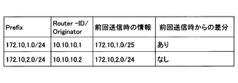
- the route information table 116 stores route information such as BGP and IP. For example, the network information in the AS exchanged by the router by BGP and the address of the router are stored. Since it is assumed that the information amount of the route information table 116 will be large, information including changes from the previous time may be stored based on the information of the BGP table and the IP route table of the controller 100.
- the information management unit 112 acquires IGP link state information and route information such as BGP and IP from a communication device in the management network via the communication unit 111 using a protocol such as BGP-LS.
- the communication device from which the link state information and the route information are acquired is mainly the anchor node, but the communication device may acquire the information from another communication device.
- the Maximum SID Depth advertised in IGP is acquired, and the upper limit U of the label push number is determined.
- the upper limit U of the label push number is passed to the path compression device 130 described later and stored in the compression information table 135.
- the information management unit 112 stores the acquired link state information and route information in the link state information table 115 and the route information table 116 after performing a calculation such as sorting using the label information as a key.
- the link state information calculation unit 113 calculates the link usage rate and the like and then stores the link state information in the link state information table 115 in a predetermined format. ..
- the information management unit 112 determines the transmission interval and the data content to be transmitted from the data transmission information table 114, and transmits the data of the link state information table 115 and the route information table 116 to the SR route creation device 120 via the communication unit 111. .. At this time, according to the content of the data transmission information table 114, all information may be transmitted to the SR route creation device 120 each time, or only the difference information from the previous transmission may be transmitted.
- FIG. 15 is a diagram showing an example of the SR route creation device 120.
- the SR route creation device 120 includes a communication unit 121, an SR route creation unit 122, and a policy information table 123.
- FIG. 16 shows an example of the policy information table 123.
- the policy information table 123 stores a routing policy for satisfying the requirements on the application side.
- policy 1 is a policy used when diverting traffic to a specific security device.
- the SR route creation unit 122 uses the policy information determined by the application (designation of a node to pass through, avoidance of a specific link, etc.) and NW information received from the NW information acquisition device 110 via the communication unit 121 at regular intervals. Based on this, the SR route information is determined. This corresponds to step S102 in FIG. The SR route information is specified by the label of the node or link to be passed. The SR route creation unit 122 transmits the route information to the route compression device 130 via the communication unit 121.
- FIG. 17 is a diagram showing an example of the route compression device 130.
- the route compression device 130 includes a communication unit 131, an anchor node information extraction unit 132, a compression calculation unit 133, an anchor node information table 134, and a compression information table 135.
- FIG. 18 shows an example of the anchor node information table 134. As shown in FIG. 18, for each anchor node, regardless of the type of label such as Node-ID and Peer-SID, the related label information SID is collected.
- the anchor node is specified in advance, and the anchor node information extraction unit 132 acquires information such as a BGP table from the NW information acquisition device 110 via the communication unit 131, and the anchor specified in advance is acquired from the acquired information.
- the node information is extracted and stored in the anchor node information table 134.
- the compression calculation unit 133 acquires SR route information from the SR route creation device 120 via the communication unit 131.
- the compression calculation unit 133 divides the label included in the route information in units of anchor nodes.
- the label information of the anchor node that can expand the BSID is acquired from the anchor node information table 134 and the route information is divided. This corresponds to steps S103 and S104 in FIG.
- the compression calculation unit 133 compresses the label included in the route information into the BSID so that the communication device on the route does not exceed the processing limit.
- the upper limit U of the number of label pushes stored in the compression information table 135 is used as the processing limit. This corresponds to steps S105 and S106 in FIG.
- the compressed labels may be merged with each other within a range not exceeding the processing limit in the communication device on the path.
- step S106 in FIG. some labels in the route information may be replaced with Node-IDs equivalent to those labels.
- This processing may be performed by sending the information of the section exceeding the upper limit U of the number of label pushes to the SR route creation device 120 and acquiring the route information corrected by the SR route creation device 120.
- the route may be terminated at any anchor node so that the communication device on the route does not exceed the processing limit.
- the compression calculation unit 133 transmits the compressed route information to the SR policy distribution device 140 via the communication unit 131.
- FIG. 19 is a diagram showing an example of the SR policy distribution device 140.
- the SR policy distribution device 140 includes a communication unit 141, an information management unit 142, and a compression path management table 143.
- FIG. 20 shows an example of the compression path management table 143.
- the compressed route management table 143 holds the result (SR policy) of the route control that the SR route creation device 120 should perform for each request condition (policy) received from the application.
- the route information of SR policy is in the form of SID list. This SID list contains the BSID in which the label is compressed, and the compressed route management table 143 holds the contents of the BSID and the information of the anchor node that expands the BSID.
- the information management unit 142 acquires the compressed route information from the route compression device 130 via the communication unit 141 and stores it in the compressed route management table 143.
- the information management unit 142 transmits the SID list of the compressed path management table 143 to the ingress router, and delivers the content of the BSID to the corresponding anchor node via the communication unit 141.
- the route SID list is sent to the ingress router, information ⁇ 10, 20, 30> for deploying BSID:100 is delivered to router A, and BSID:200 is deployed.
- BSIDs are merged into BSID', information for expanding BSID' is delivered to the corresponding anchor node.
- the information management unit 142 transmits new route information to the anchor node that terminated the route via the communication unit 141.
- a communication protocol such as PCEP can be used for the route distribution method.
- FIG. 21 is a sequence diagram showing processing in the controller 100.
- step S201 the NW information acquisition device 110 acquires NW information such as topology information from the communication device in the management network.
- step S202 the NW information acquisition device 110 processes the acquired NW information and transmits it to the SR route creation device 120 in step S203.
- step S204 the SR route creation device 120 creates SR route information based on the request from the application and the NW information, and transmits the result to the route compression device 130 in step S205.
- step S206 the route compression device 130 identifies the SID of the anchor node from the SIDs included in the candidate route and divides the SID to create a BSID.
- step S207 it is determined whether the processing limit of the router is exceeded when transferring by the BSID, the BSID is merged and the route information is reviewed according to the determination result, and the compressed route is transmitted to the SR policy distribution device 140 in step S207.
- the SR policy distribution device 140 registers the compression route, and transmits the compression route to the communication device in step S209.
- a router suitable for BSID expansion can be selected from routers (anchor nodes) that can expand BSID, and the number of labels after expansion can be processed by the router. It can be kept below the limit.
- the method of the embodiment of the present invention after dividing into BSIDs in units of anchor nodes, it is possible to perform merging by observing the insufficient number of labels. This makes it possible to determine which router should be set as the anchor node. Also, the number of times the SR-TE path is terminated can be reduced.
- ASBR21 becomes an anchor node for expanding BSIDs.
- the number of BSIDs is small, but the number of SIDs to be ingress pushed increases, and the number of label pushes in ingress may exceed the upper limit U. Also, if the NW in the AS is huge, the number of label pushes may even exceed the upper limit U only by the routing in the AS.
- ABR11, ASBR21, ABR23 become anchor nodes for expanding BSIDs.
- the number of SIDs pushed in Ingress is small, but the number of BSIDs increases as the number of areas increases, so the number of label pushes in Ingress may exceed the upper limit U.
- the embodiment of the present invention it is not fixed assignment of AS unit or area unit, but suitable for deployment of BSID that minimizes BSID while satisfying the upper limit of the number of labels that can be pushed.
- ABR11 and ASBR21 are the anchor nodes that expand the BSID. Since the labels can be specified by the number of BSIDs saved by merging BSIDs, flexible routing control can be realized in the entire network.
- the embodiment of the present invention it is not fixed allocation of AS unit or area unit, but suitable for deployment of BSID that minimizes BSID while satisfying the upper limit of the number of labels that can be pushed.
- ABR11 and ASBR21 are the anchor nodes that expand the BSID. Since the labels can be specified by the number of BSIDs saved by merging BSIDs, flexible routing control can be realized in the entire network.
- FIG. 28 shows a hardware configuration example of the controller 100 according to the embodiment of the present invention.
- the controller 100 may be a computer including a processor such as a CPU (Central Processing Unit) 151, a memory device 152 such as a RAM (Random Access Memory) and a ROM (Read Only Memory), and a storage device 153 such as a hard disk.
- a processor such as a CPU (Central Processing Unit) 151
- a memory device 152 such as a RAM (Random Access Memory) and a ROM (Read Only Memory)
- a storage device 153 such as a hard disk.
- the functions and processing of the controller 100 are realized by the CPU 151 executing data and programs stored in the storage device 153 or the memory device 152.
- the input of data to the controller 100 may be performed from the input/output interface device 154, and the output of data from the controller 100 may be performed from the input/output interface device 154.
- the device according to the embodiment of the present invention is described using a functional block diagram, but the device according to the embodiment of the present invention may be implemented by hardware, software, or a combination thereof.
- the embodiment of the present invention includes a program that causes a computer to realize the functions of the device according to the embodiment of the present invention, a program that causes a computer to execute each step of the method according to the embodiment of the present invention, and the like. May be realized.
- each functional unit may be used in combination as necessary.
- the methods according to the embodiments of the present invention may be performed in a different order from the order shown in the embodiments.
- controller 110 NW information acquisition device 111 communication unit 112 information management unit 113 link state information calculation unit 114 data transmission information table 115 link state information table 116 route information table 120 SR route creation device 121 communication unit 122 SR route creation unit 123 policy information Table 130 Route compression device 131 Communication unit 132 Anchor node information extraction unit 133 Compression calculation unit 134 Anchor node information table 140 SR policy distribution device 141 Communication unit 142 Information management unit 143 Compressed route management table
Landscapes
- Engineering & Computer Science (AREA)
- Computer Networks & Wireless Communication (AREA)
- Signal Processing (AREA)
- Data Exchanges In Wide-Area Networks (AREA)
Abstract
複数の通信装置で構成されたネットワークにおいて、当該複数の通信装置のうち予め指定された1つ以上のアンカーノードを制御する制御装置は、入力された要求条件に基づき、経由すべき通信装置又はリンクのラベルを含む経路情報を作成する経路作成部と、前記経路情報に含まれるラベルをアンカーノード単位で分割し、前記経路情報に基づいて決定される通信装置の処理限界を超えないように、前記経路情報に含まれるラベルのうち少なくとも一部を、前記経路情報に基づいて決定される通信装置のうち少なくとも1つのアンカーノードにおいて展開できる圧縮ラベルに圧縮する経路圧縮部と、前記圧縮ラベルを展開するための情報を前記少なくとも1つのアンカーノードに配信する配信部とを有する。
Description
本発明は、制御装置、制御方法及びプログラムに関する。
柔軟なTE(Traffic Engineering)やSFC(Service Function Chaining)を実現するネットワーク技術として、SR(Segment Routing)が注目されている。
例えば、DDoS(Distributed Denial of Service)攻撃等の大量トラヒックや、特定の動画の視聴等によるバースト的なトラヒックの増加に対し、各リンクの帯域使用率を常時取得し、トラヒックの流入口(GW(Gateway)等)でSRによる制御を行うことで、使用率の低いリンクにトラヒックを誘導することができる。
SRをMPLS(Multi-Protocol Label Switching)網に適用したSR-MPLSはMPLSのスケール性向上及びシンプル化を図ることができる。SR-MPLSでは、SID(Segment ID)というラベルが用いられ、IGP(Interior Gateway Protocol)を拡張したプロトコル(拡張IGP)で、経路広告にSIDが付加されて経路情報が交換される。パケット転送時には、パケット内にスタックされたラベルが経路情報テーブルの役割を果たすため、途中のルータは、SRのポリシーを理解していれば全ての経路情報を保持する必要はない。
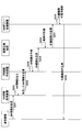
SR-MPLSにおいて、Node-ID、Adj-SID(Adjacency-SID)、Peer-SIDと呼ばれる3種類のSIDが用いられる。Node-IDはノード毎に定義され、IGPの最短経路に従ってノードに転送するときに用いられる。Adj-SIDはインタフェース毎に定義され、明示的に経由すべきリンクを指定するときに用いられる。Peer-SIDはAS(Autonomous System)間の転送のために用いられる。図1に、SR-MPLSにおける経路指定の概要を示す。例えば、ノードAからノードDまでIGPで定める最短経路で転送する場合、ノードAが送信するパケットに対してノードD(Node-ID)のラベルを設定する。例えば、ノードAからノードDまで最短経路で転送するのではなく、C-E間のリンクを経由させたい場合、ノードAが送信するパケットに対して、ノードC(Node-ID)とC-E間のリンク(Adj-ID)とノードD(Node-ID)のラベルを設定する。これらのラベル設定はコントローラ等の外部装置から行うことができる。
PCE Working Group Internet-Draft, "Carrying Binding Label/Segment-ID in PCE based Networks", draft-sivabalan-pce-binding-label-sid-05, October 19, 2018
SPRING Working Group Internet-Draft, "Segment Routing Policy Architecture", draft-ietf-spring-segment-routing-policy-02, October 22, 2018
Rabah Guedrez, et.al, "Label Encoding Algorithm for MPLS Segment Routing", March 2017
"The critical role of Maximum SID Depth (MSD) hardware limitations in Segment Routing ecosystem and how to work around those", NANOG71, October 2017, インターネット<URL:https://pc.nanog.org/static/published/meetings/NANOG71/1424/20171004_Tantsura_The_Critical_Role_v1.pdf>, 2019年1月8日検索
SR-MPLSによるTEでは、パケットに多数のラベルがスタックされることが想定される。例えば、輻輳回避等のユースケースでは、トラヒックを通したいリンクを直接指定したTEを行う必要がある。故障によるリンクコストの変化に対してロバストに経路制御するためには、TEしたいリンクを個別に指定することが重要になる。図1から明らかなように、リンクを指定する毎に、パケットにスタックされるラベル数が増加する。また,マルチエリア・マルチASで構成されるネットワークにおいて,SRを適用する場合に,隣接エリアやASとの境界になるエリアボーダールーター(ABR)やASボーダールーターを経由する必要があり,明示的にSIDをスタックする必要がある。
その結果、パケットにスタックされるラベル数がルータの処理限界を超過することも考えられ、この場合、SRによる柔軟なトラヒック制御は困難となる。また、パケットにスタックされるラベル数の増加に伴い、オーバーヘッドが増大する。
従来、複数のSID(ラベル)を単一のBSID(Binding SID)に置き換える(圧縮する)ことで、スタックされるラベル数を一時的に削減することが検討されている(非特許文献1、2)。例えば、コントローラが<16003,16004>という複数のラベルを、1つのBSID<40164>に圧縮し、一部のルータ(GW等)に広告する。BSID<40164>を広告されたルータは、BSID<40164>が付与されたパケットを受け取った際、元のラベルのリスト<16003,16004>に変換(展開)し、展開後のSIDに従い転送する。
しかし、BSIDをAS単位で割り当てる場合、AS内におけるTEのために多数のラベルが必要になる。仮にASを複数のエリアに分割してBSIDをエリア単位で割り当てたとしても、入口(Ingress)ルータにおいてプッシュするBSIDがエリア数の増加に伴って増加するため、多数のラベルが必要となる。
本発明は、SRにおいてパケットにスタックされるラベル数を削減するための方式を提案する。
本発明の一形態に係る制御装置は、
複数の通信装置で構成されたネットワークにおいて、当該複数の通信装置のうち予め指定された1つ以上のアンカーノードを制御する制御装置であって、
入力された要求条件に基づき、経由すべき通信装置又はリンクのラベルを含む経路情報を作成する経路作成部と、
前記経路情報に含まれるラベルをアンカーノード単位で分割し、前記経路情報に基づいて決定される通信装置の処理限界を超えないように、前記経路情報に含まれるラベルのうち少なくとも一部を、前記経路情報に基づいて決定される通信装置のうち少なくとも1つのアンカーノードにおいて展開できる圧縮ラベルに圧縮する経路圧縮部と、
前記圧縮ラベルを展開するための情報を前記少なくとも1つのアンカーノードに配信する配信部と、
を有することを特徴とする。
複数の通信装置で構成されたネットワークにおいて、当該複数の通信装置のうち予め指定された1つ以上のアンカーノードを制御する制御装置であって、
入力された要求条件に基づき、経由すべき通信装置又はリンクのラベルを含む経路情報を作成する経路作成部と、
前記経路情報に含まれるラベルをアンカーノード単位で分割し、前記経路情報に基づいて決定される通信装置の処理限界を超えないように、前記経路情報に含まれるラベルのうち少なくとも一部を、前記経路情報に基づいて決定される通信装置のうち少なくとも1つのアンカーノードにおいて展開できる圧縮ラベルに圧縮する経路圧縮部と、
前記圧縮ラベルを展開するための情報を前記少なくとも1つのアンカーノードに配信する配信部と、
を有することを特徴とする。
また、本発明の一形態に係る制御方法は、
複数の通信装置で構成されたネットワークにおいて、当該複数の通信装置のうち予め指定された1つ以上のアンカーノードを制御する制御装置が実行する制御方法であって、
入力された要求条件に基づき、経由すべき通信装置又はリンクのラベルを含む経路情報を作成するステップと、
前記経路情報に含まれるラベルをアンカーノード単位で分割し、前記経路情報に基づいて決定される通信装置の処理限界を超えないように、前記経路情報に含まれるラベルのうち少なくとも一部を、前記経路情報に基づいて決定される通信装置のうち少なくとも1つのアンカーノードにおいて展開できる圧縮ラベルに圧縮するステップと、
前記圧縮ラベルを展開するための情報を前記少なくとも1つのアンカーノードに配信するステップと、
を有することを特徴とする。
複数の通信装置で構成されたネットワークにおいて、当該複数の通信装置のうち予め指定された1つ以上のアンカーノードを制御する制御装置が実行する制御方法であって、
入力された要求条件に基づき、経由すべき通信装置又はリンクのラベルを含む経路情報を作成するステップと、
前記経路情報に含まれるラベルをアンカーノード単位で分割し、前記経路情報に基づいて決定される通信装置の処理限界を超えないように、前記経路情報に含まれるラベルのうち少なくとも一部を、前記経路情報に基づいて決定される通信装置のうち少なくとも1つのアンカーノードにおいて展開できる圧縮ラベルに圧縮するステップと、
前記圧縮ラベルを展開するための情報を前記少なくとも1つのアンカーノードに配信するステップと、
を有することを特徴とする。
また、本発明の一形態に係るプログラムは、
上記の制御装置の各部としてコンピュータを機能させることを特徴とする。
上記の制御装置の各部としてコンピュータを機能させることを特徴とする。
本発明によれば、SRにおいてパケットにスタックされるラベル数を削減することが可能になる。
以下、図面に基づいて本発明の実施例について説明する。
<ネットワークの論理構成>
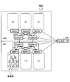
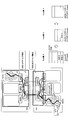
まず、図2を参照して、本発明の実施例を説明するためのネットワークの論理構成について説明する。図2に示すように、ネットワークは複数の通信装置(以下、ルータ、ノード等とも呼ばれる)で構成される。ネットワークは、統一された運用ポリシーで管理されたAS(AS1、AS2等)に分割される。ASと外部のネットワークとの境界に置かれるルータ(ASBR11、ASBR12等)をASBR(AS Boundary Router)と呼ぶ。また、ASはバックボーンエリア及び複数のサブエリアに分割して管理することができる。各サブエリアはサブエリア間を接続するバックボーンエリアに隣接しており、バックボーンエリアと各サブエリアの境界に置かれるルータ(ABR11、ABR12、ABR13等)をABR(Area Border Router)と呼ぶ。すなわち、図2において、AS1のサブエリアが(1)であり、AS1のバックボーンエリアが(2)であり、AS2のバックボーンエリアが(3)であり、AS2のサブエリアが(4)である。
まず、図2を参照して、本発明の実施例を説明するためのネットワークの論理構成について説明する。図2に示すように、ネットワークは複数の通信装置(以下、ルータ、ノード等とも呼ばれる)で構成される。ネットワークは、統一された運用ポリシーで管理されたAS(AS1、AS2等)に分割される。ASと外部のネットワークとの境界に置かれるルータ(ASBR11、ASBR12等)をASBR(AS Boundary Router)と呼ぶ。また、ASはバックボーンエリア及び複数のサブエリアに分割して管理することができる。各サブエリアはサブエリア間を接続するバックボーンエリアに隣接しており、バックボーンエリアと各サブエリアの境界に置かれるルータ(ABR11、ABR12、ABR13等)をABR(Area Border Router)と呼ぶ。すなわち、図2において、AS1のサブエリアが(1)であり、AS1のバックボーンエリアが(2)であり、AS2のバックボーンエリアが(3)であり、AS2のサブエリアが(4)である。
コントローラと呼ばれる制御装置100は、ASBR及びABRからトポロジ情報等のNW情報を取得することができ、ASBR及びABRに対して指定の処理(ポリシーとも呼ばれる)を実行させることができる。このようにコントローラ100とピアを貼り、コントローラ100が制御することができるルータをアンカーノードと呼ぶ。以下の実施例ではアンカーノードがASBR及びABRである例について説明するが、アンカーノードはASBR及びABRに限定されることなく、ネットワーク内のどの通信装置がアンカーノードとして指定されてもよい。また、全てのASBR及びABRが必ずしもアンカーノードとなる必要はなく、アンカーノードはネットワークの運用管理者により予め指定される。コントローラ100は1つのASを管理してもよく、複数のASを管理してもよい。
例えば、故障発生等によるリンクコストの変化にロバストにするため、経由するリンクを個別に指定するTEを行うことが想定される。例えば、図2のネットワークにおいて、ASの入口ルータであるASBR(図示せず)から、AS1内のノード1→ノード4→ノード8→ASBR11→ASBR12を経由するためのTEを実現するには、AS1内だけで5つのラベルが必要となる。
ここで、図3を参照して、複数のSID(ラベル)を単一のBSIDに置き換える方式(非特許文献1、2)について検討する。
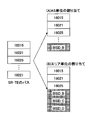
まず、BSIDをAS単位で割り当てることを想定する。例えば、図2においてAS1内でTEに用いるSIDをBSID_Aに圧縮し、AS2内でTEに用いるSIDをBSID_Bに圧縮する。AS1内でTEに用いるSIDが<16015, 16021, 16025, …>であり、AS2内でTEに用いるSIDが<18021>であることを仮定する。AS2内のSIDをBSID_Bに圧縮した場合、図3(A)に示すように、入口ルータにプッシュするラベルは<16015, 16021, 16025, …, BSID_B>である。このように、AS1内のTEだけで多数のラベルが必要となり、ラベル数がルータの処理限界を超過する可能性がある。
次に、BSIDをエリア単位で割り当てることを想定する。例えば、図2においてAS1のサブエリア(1)内でTEに用いるSIDをBSID_Aに圧縮し、AS1のバックボーンエリア(2)内でTEに用いるSIDをBSID_Bに圧縮し、AS2のバックボーンエリア(3)内でTEに用いるSIDをBSID_Cに圧縮し、AS2のサブエリア(4)内でTEに用いるSIDをBSID_Dに圧縮する。この場合、入口ルータから最寄のABR11までのラベル数を減らすことができるが、図3(B)に示すように、エリア数分のBSID(BSID_B, BSID_C, BSID_D)が必要となるため、ラベル数が増加してルータの処理限界を超過する可能性がある。
したがって、ルータの処理限界を超過しないようなラベル数削減方式が必要となる。
<ラベル数削減方式>
図4を参照して、L個のSIDから構成される経路情報が与えられるとき、制約を満たす(ラベルプッシュ数の上限U(U<L)を満たし、BSIDを展開できるノードはアンカーノードとする)方式について説明する。図4は、本発明の実施例におけるラベル数削減方式を示すフローチャートである。なお、以下の説明ではルータの処理限界に関する制約としてラベルプッシュ数の上限Uの例を説明するが、ルータの処理限界に関する制約はラベルスタック数又はホップ数でもよい。
図4を参照して、L個のSIDから構成される経路情報が与えられるとき、制約を満たす(ラベルプッシュ数の上限U(U<L)を満たし、BSIDを展開できるノードはアンカーノードとする)方式について説明する。図4は、本発明の実施例におけるラベル数削減方式を示すフローチャートである。なお、以下の説明ではルータの処理限界に関する制約としてラベルプッシュ数の上限Uの例を説明するが、ルータの処理限界に関する制約はラベルスタック数又はホップ数でもよい。
ステップS101において、コントローラ100は各ルータのラベルプッシュ数の上限Uを取得する。
コントローラ100はBGP-LS(BGP-Link State)等のプロトコルにより、アンカーノード(ASBR及びABR)から各AS/エリアのトポロジ情報を取得する。トポロジ情報の中には、IGPで広告されるプッシュ可能なラベル数の情報(Maximum SID Depth)も含まれる。コントローラ100は、コントローラ100が管理するネットワーク内のルータにおけるMaximum SID Depthの最小値をUとして決定する。なお、Uはネットワーク内で一意に決める必要はなく、エリア毎に決めることも可能である。エリア毎に決める場合、コントローラ100はエリア毎にエリアiの最小値Uiを決定し、ステップS105の計算に用いてもよい。また、Uはネットワーク内で用いられる通信装置の仕様から予め決められた値としてもよい。なお、Uは経路制御(SR)の制約条件となるため、以下のステップS102において決定される経路上の通信装置の処理限界を超えない範囲であれば如何なる値が用いられてもよい。
ステップS102において、コントローラ100はTEの要求条件に基づき、L個のSIDから構成される経路情報(SR-TEパス)を作成する。
要求条件はユーザの要求によって決まり、例えば、遅延や特定リンクの回避等のTEの要求、サービスチェイニングの要求、標的の要求等がある。コントローラ100は、要求条件に基づき、経由すべきノードやリンクやピアのSIDを特定し、SR-TEパスを作成する。
SR-TEパスに含まれるSIDは、コントローラ100の保持する情報からリアルタイムに特定してもよい。ASBR及びABRのようなアンカーノードは予め指定されており、コントローラ100はASBRのアドレスとAS番号との対応関係を保持している。また、ステップS101においてコントローラ100はBGP-LS等のプロトコルにより、ASBRから取得したSID(Node-ID、Adj-SID、Peer-SID)を保持している。これらのSIDを用いて、SR-TEパスを構成するSIDのリストが作成できる。
ステップS103において、コントローラ100はSR-TEパスを構成するSIDの中から、BSIDを展開できるアンカーノード(H_1,…,H_M)のSIDを特定する。
ここでは、ステップS102で生成したSR-TEパスを構成するSIDのうち、コントローラ100がBGP-LS等のプロトコルにより取得して保有している情報や、ステップS102においてSIDの特定のために用いた情報から、BSIDを展開できるアンカーノード(H_1,…,H_M)のSIDを特定する。図5(A)に、L=9個のSIDから構成されるSR-TEパスから、BSIDを展開できるM=3個のアンカーノードを特定したときの例を示す。
ステップS104において、コントローラ100は各BSIDの最後のラベルがアンカーノード(H_1,…,H_M)のSIDになるよう、L個のSIDのリストをM個のBSIDに分割する。
アンカーノードはコントローラ100の指示によって次のBSIDを展開する役目を持つため、SR-TEパスを構成するSIDのリストをアンカーノード(H_1,…,H_M)単位で分割する。具体的には、SR-TEパスに含まれるSIDがアンカーノードのSIDに一致したときに、そのSIDの直後で分割する。また、SR-TEパスに含まれるSIDがPeer-SIDに一致したときにはアンカーノードとなるABSRが存在することが分かるため、そのSIDの直後で分割する。分割後のパス毎にBSIDを設定する。図5(B)に、SR-TEパスを構成するSIDのリストをM=3個のBSIDに分割したときの例を示す。
ステップS105において、コントローラ100は各アンカーノード(H_1,…,H_{M-1})でのラベルプッシュ数がUを下回るか判定し、超過数R_i=U-(H_iのラベルプッシュ数)を計算する。
SIDのリストをBSIDに分割することにより、SIDのリストの一部をBSIDに圧縮することができる。図5(B)において分割したラベル<1, 2, 3, H_1>は、アンカーノードH_0において展開できるBSID1に圧縮され、ラベル<4, H_2>は、アンカーノードH_1において展開できるBSID2に圧縮され、ラベル<5, 6, H_3>は、アンカーノードH_2において展開できるBSID3に圧縮される。なお、ラベル<1, 2, 3, H_1>はアンカーノードH_0から送信されるときに展開されている必要があるため、<1, 2, 3, H_1>は圧縮されなくてもよい。この時点で各アンカーノードでのラベルプッシュ数がU以下である場合、以下のステップは実行する必要はない。
図5(B)に示すラベルを圧縮した後、各アンカーノードH_0, H1, H_2においてプッシュするラベルを図6に示す。図6に示すように、入口ルータとなるH_0ではBSID1の全SIDと、BSID2以降の全BSIDをプッシュする必要がある。U=5であると仮定すると、H_0においてBSID1を展開したときのラベルプッシュ数は6であり、超過数R_0=1である。H_1ではBSID2のみを展開して<4, H_2>をプッシュするため、ラベルプッシュ数は2であり、超過数R_1=-3である。H_2ではBSID3のみを展開して<5, 6, H_3>をプッシュするため、ラベルプッシュ数は3であり、超過数R_2=-2である。
ステップS106において、R_i>H_{i-1}のラベルプッシュ数の場合、コントローラ100は隣接するBSID同士をマージすることで、BSID数を削減する。ただし、マージ後のラベルプッシュ数はU以下でなければならない。コントローラ100はBSID同士をマージした後にR_iを更新する。
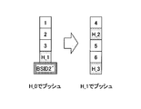
図6においてH_1においてプッシュするラベル<4, H_2>と、H_2においてプッシュするラベル<5, 6, H_3>をマージすることを仮定すると、マージ後のラベルプッシュ数は2+3=5となり、U以下となる。すなわち、BSID2とBSID3は新たなBSID2'にマージ可能である。このようにマージしたときのアンカーノードH_0,H_1においてプッシュするラベルを図7に示す。図7に示すように、H_0でプッシュするラベルは<1, 2, 3, H_1, BSID2'>に削減され、ラベルプッシュ数は5であり、超過数R_0=0である。H_1でプッシュするラベルは<4, H_2, 5, 6, H_3>であり、ラベルプッシュ数は5であり、超過数R_1=0である。
ステップS107において、コントローラ100はR_i>0となるBSIDで、SIDのリストの縮約を実行する。
SIDのリストの縮約には既存技術(非特許文献3、4)を用いることができる。具体的には、SIDのリストの中の一部のパスがその端点となるNode-IDで置き換えることができるか否かを確認し、置き換え可能な場合にはSIDのリストを縮約できる。例えば、図8に示すHeadendノードからTailendノードまでに通過するリンクを指定するために3つのAdj-SIDを用いていたことを想定する。図8のリンク付近の数字はコストである。この例ではHeadendノードからTailendノードまでのパスは最短パスであるため、3つのAdj-SIDはTailendノードの1つのNode-IDで置き換えることができる。
ステップS108において、上記のステップS107において解なしとなった場合(すなわち、R_i>0となる場合)、コントローラ100はラベルプッシュ数の上限Uを超過するBSIDの区間で一度SR-TEパスを終端することで、ラベルプッシュ数の上限を超過しないようにする。
例えば、図9に示すように、入口ルータを含むサブエリアにおいて多数のラベルを付与してTEを行う場合、バックボーン以降のルーティングのためのBSIDを付与したときにラベルプッシュ数がルータの上限を超える可能性がある。この場合、最初に通過するABRにおいてSR-TEパスを終端して、SR-TEパスを終端したABRを新たなHeadendとして再びラベルをプッシュし直す。
或いは、アンカーノード毎に圧縮したBSIDのリストを新たなBSIDとして再定義してもよい。例えば、図6におけるBSID2及びBSID3を新たなBSID2'として再定義することで、図6においてH_0でプッシュするラベル数は5に削減することができる。この場合、H_1ではBSID2'をBSID2とBSID3に展開し、更に、BSID2を<4, H_2>に展開する。
上記の手順によってラベルを圧縮した後、コントローラ100はPCEP(Path Computation Element Protocol)やNetconf等のプロトコルを用いてSRポリシー(SR-TEパスと、SR-TEパスに含まれるBSIDを展開するための情報)を経路上のアンカーノードに配信する。
<コントローラの機能構成>
図10に、本発明の実施例におけるコントローラ100の構成を示す。コントローラ100は、図2を参照して説明したネットワークを管理する装置群である。コントローラ100が管理するネットワークを管理ネットワークと呼ぶ。管理ネットワークは、例えば、ISP(Internet Service Provider)網等のインターネットと、アクセス網/ユーザネットワークとを接続する大規模なSR-MPLS網である。コントローラ100は、NW情報取得装置110と、SR経路作成装置120と、経路圧縮装置130と、SRポリシー配信装置140とを含む。なお、コントローラ100は、上記の装置群のうち一部の機能を含む制御装置として構成されてもよい。
図10に、本発明の実施例におけるコントローラ100の構成を示す。コントローラ100は、図2を参照して説明したネットワークを管理する装置群である。コントローラ100が管理するネットワークを管理ネットワークと呼ぶ。管理ネットワークは、例えば、ISP(Internet Service Provider)網等のインターネットと、アクセス網/ユーザネットワークとを接続する大規模なSR-MPLS網である。コントローラ100は、NW情報取得装置110と、SR経路作成装置120と、経路圧縮装置130と、SRポリシー配信装置140とを含む。なお、コントローラ100は、上記の装置群のうち一部の機能を含む制御装置として構成されてもよい。
NW情報取得装置110は、管理ネットワーク内のアンカーノード等からトポロジ情報等のNW情報を取得する。SR経路作成装置120は、NW情報取得装置110が取得したNW情報とアプリケーションからの要求条件に基づき、SRポリシーとして配信する経路情報を作成する。この経路情報は、経由すべき通信装置又はリンクのラベルをSIDのリストの形式で表現したものである。経路圧縮装置130は、SR経路作成装置120が作成した経路情報のラベルをBSIDに圧縮する。ラベルの圧縮は図4に示すフローチャートに従って行われる。SRポリシー配信装置140は、経路情報と、BSIDを展開するための情報をSRポリシーとして経路上のアンカーノードに配信する。
図11は、NW情報取得装置110の一例を示す図である。NW情報取得装置110は、通信部111と、情報管理部112と、リンクステート情報演算部113と、データ送信情報テーブル114と、リンクステート情報テーブル115と、経路情報テーブル116とを含む。
図12に、データ送信情報テーブル114の一例を示す。データ送信情報テーブル114には、SR経路作成装置120に送信するデータの範囲(送信データ範囲)や送信するデータの間隔(データ送信間隔)等、データ送信に関する情報を格納する。送信データ範囲は、リンクステート情報テーブル115及び経路情報テーブル116に格納する情報を決定するために用いられる。
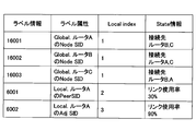
図13に、リンクステート情報テーブル115の一例を示す。リンクステート情報テーブル115には、BGP-LS等のプロトコルを用いて取得したリンクステート情報を加工したものが格納される。ラベル情報はSIDであり、リンクステート情報テーブル115にはSIDをキーとして管理ネットワークのトポロジ情報が格納される。例えば、SID毎に、そのSIDの種類、Local index、リンクステート情報(接続先の情報等)が格納される。SIDがリンクを示すAdj-SIDやPeer-SIDである場合、リンクステート情報はリンク使用率のような情報に加工される。
図14に、経路情報テーブル116の一例を示す。経路情報テーブル116には、BGP、IP等の経路情報が格納される。例えば、ルータがBGPによって交換したAS内のネットワーク情報とルータのアドレスとの情報等が格納される。経路情報テーブル116の情報量は大きくなることが想定されるため、コントローラ100の持つBGPテーブルやIPルートテーブルの情報に基づき、前回からの変更を含めた情報を格納してもよい。
情報管理部112は、管理ネットワーク内の通信装置から通信部111を介して、BGP-LS等のプロトコルを用いて、IGPのリンクステート情報やBGP、IP等の経路情報を取得する。リンクステート情報や経路情報の取得先の通信装置は、主にアンカーノードであるが、他の通信装置から情報を取得してもよい。ここで、IGPで広告されるMaximum SID Depthが取得され、ラベルプッシュ数の上限Uが決定される。ラベルプッシュ数の上限Uは、後述する経路圧縮装置130に渡され、圧縮情報テーブル135に格納される。情報管理部112は、ラベル情報をキーにしたソート等の演算を行なった後、取得したリンクステート情報や経路情報をリンクステート情報テーブル115及び経路情報テーブル116に格納する。なお、リンクステート情報をリンクステート情報テーブル115に格納する際に、リンクステート情報演算部113は、リンク使用率等の演算を行った後、予め決められた形式でリンクステート情報テーブル115に格納する。情報管理部112は、データ送信情報テーブル114から送信間隔や送信するデータ内容を決定し、通信部111を介してリンクステート情報テーブル115及び経路情報テーブル116のデータをSR経路作成装置120に送信する。このとき、データ送信情報テーブル114の内容に従って、毎回全ての情報をSR経路作成装置120に送信してもよいし、前回送信時との差分情報だけを送信してもよい。
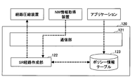
図15は、SR経路作成装置120の一例を示す図である。SR経路作成装置120は、通信部121と、SR経路作成部122と、ポリシー情報テーブル123とを含む。
図16に、ポリシー情報テーブル123の一例を示す。ポリシー情報テーブル123には、アプリケーション側の要求条件を満たすためのルーティングポリシーが格納される。例えば、ポリシー1は、トラヒックを特定のセキュリティ装置に迂回する際に用いられるポリシーである。
SR経路作成部122は、アプリケーションで決定したポリシー情報(経由すべきノード等の指定や、特定リンクの回避等)やNW情報取得装置110から通信部121を介して一定間隔で受信したNW情報に基づき、SRの経路情報を決定する。これは図4のステップS102に対応する。SRの経路情報は、経由すべきノードやリンクのラベルで指定される。SR経路作成部122は、経路情報を通信部121を介して経路圧縮装置130に送信する。
図17は、経路圧縮装置130の一例を示す図である。経路圧縮装置130は、通信部131と、アンカーノード情報抽出部132と、圧縮演算部133と、アンカーノード情報テーブル134と、圧縮情報テーブル135とを含む。
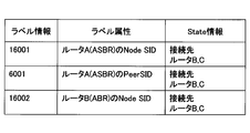
図18に、アンカーノード情報テーブル134の一例を示す。図18に示すように、アンカーノード毎に、Node-ID、Peer-SID等といったラベルの種類は問わず、関与するラベル情報SIDがまとめられる。
アンカーノードは予め指定されており、アンカーノード情報抽出部132は、NW情報取得装置110から通信部131を介してBGPテーブル等の情報を取得し、取得した情報の中から、予め指定されたアンカーノードの情報を抽出してアンカーノード情報テーブル134に格納する。
圧縮演算部133は、SR経路作成装置120から通信部131を介してSRの経路情報を取得する。圧縮演算部133は、経路情報に含まれるラベルをアンカーノード単位で分割する。このとき、BSIDを展開できるアンカーノードのラベル情報をアンカーノード情報テーブル134から取得して経路情報の分割を行う。これは図4のステップS103及びS104に対応する。圧縮演算部133は、経路上の通信装置において処理限界を超えないように、経路情報に含まれるラベルをBSIDに圧縮する。なお、処理限界は圧縮情報テーブル135に格納されているラベルプッシュ数の上限Uを用いる。これは図4のステップS105及びS106に対応する。このとき、経路上の通信装置において処理限界を超えない範囲で圧縮ラベル同士をマージしてもよい。これは図4のステップS106に対応する。また、経路情報の中のいくつかのラベルを、それらのラベルと等価なNode-IDに置き換えてもよい。この処理は、ラベルプッシュ数の上限Uを超える区間の情報をSR経路作成装置120に送り、SR経路作成装置120において修正した経路情報を取得することにより行われてもよい。これは図4のステップS107に対応する。さらに、経路上の通信装置において処理限界を超えないように、いずれかのアンカーノードで経路を終端してもよい。これは図4のステップS108に対応する。圧縮演算部133は、圧縮した経路情報を通信部131を介してSRポリシー配信装置140に送信する。
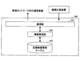
図19は、SRポリシー配信装置140の一例を示す図である。SRポリシー配信装置140は、通信部141と、情報管理部142と、圧縮経路管理テーブル143とを含む。
図20に、圧縮経路管理テーブル143の一例を示す。圧縮経路管理テーブル143には、SR経路作成装置120がアプリケーションから受信した要求条件(ポリシー)ごとに行うべき経路制御の結果(SRポリシー)が保持される。SRポリシーの経路情報はSIDリストの形式となっている。このSIDリストにはラベルを圧縮したBSIDが入っており、圧縮経路管理テーブル143はBSIDの内容とBSIDを展開するアンカーノードの情報を保持する。
情報管理部142は、経路圧縮装置130から通信部141を介して圧縮した経路情報を取得し、圧縮経路管理テーブル143に格納する。情報管理部142は、圧縮経路管理テーブル143のSIDリストを入口ルータに送信し、BSIDの内容を通信部141を介して該当するアンカーノードに配信する。例えば、SRポリシー2のとき、経路のSIDリストを入口ルータに送信し、BSID:100を展開するための情報<10, 20, 30>をルータAに配信し、BSID:200を展開するための情報<16005>をルータBに配信する。BSID同士をBSID'にマージしている場合、BSID'を展開するための情報を該当するアンカーノードに配信する。例えば、SRポリシー2'のとき、BSID':100を展開するための情報<10,20,30,16005>をルータAに配信する。なお、途中で経路を終端したとき、情報管理部142は、経路を終端したアンカーノードに対して新たな経路情報を通信部141を介して送信する。経路の配信方法はPCEP等の通信プロトコルを用いることができる。
図21は、コントローラ100における処理を示すシーケンス図である。
ステップS201において、NW情報取得装置110は、管理ネットワーク内の通信装置からトポロジ情報等のNW情報を取得する。ステップS202において、NW情報取得装置110は、取得したNW情報を加工し、ステップS203においてSR経路作成装置120に送信する。ステップS204において、SR経路作成装置120は、アプリケーションからの要求とNWの情報を踏まえ、SRの経路情報を作成し、ステップS205において結果を経路圧縮装置130に送信する。ステップS206において、経路圧縮装置130は、候補経路に含まれるSIDの中からアンカーノードのSIDを特定し、SIDを分割することでBSIDを作成する。その後、BSIDによる転送時にルータの処理限界を超過しないかを判定し、判定結果に応じてBSIDのマージや経路情報の見直しを行い、ステップS207において圧縮経路をSRポリシー配信装置140に送信する。ステップS208において、SRポリシー配信装置140は、圧縮経路を登録し、ステップS209においてこの圧縮経路を通信装置に送信する。
<実施例の効果>
上記のように、本発明の実施例によれば、BSIDを展開できるルータ(アンカーノード)の中から、BSIDの展開に適したルータを選択することができ、展開後のラベル数をルータの処理限界以下に収めることができる。本発明の実施例の方式では、アンカーノード単位の区間でBSIDに分けた後、ラベル数の不足状況を見てマージを行うことができる。これにより、どのルータをアンカーノードとして設定すべきかが判断可能になる。また、SR-TEパスを終端する回数を削減できる。
上記のように、本発明の実施例によれば、BSIDを展開できるルータ(アンカーノード)の中から、BSIDの展開に適したルータを選択することができ、展開後のラベル数をルータの処理限界以下に収めることができる。本発明の実施例の方式では、アンカーノード単位の区間でBSIDに分けた後、ラベル数の不足状況を見てマージを行うことができる。これにより、どのルータをアンカーノードとして設定すべきかが判断可能になる。また、SR-TEパスを終端する回数を削減できる。
また、ラベル数を削減することができるため、ルータへの負荷やオーバーヘッドを抑えつつ、多数のラベルを必要とする環境においても柔軟なTEが実現可能になる。
図22~図24は、2つのASで構成されるときの実施例の有効性を示す図である。ここでU=5であり、AS1のサブエリア(1)で3つのラベルを必要とすることを仮定する。
図22に示すようにBSIDをAS単位で割り当てる場合、ASBR21がBSIDを展開するアンカーノードとなる。この場合、BSID数は少ないがIngressプッシュするSIDの数が多くなり、Ingressでのラベルプッシュ数が上限Uを上回る可能性がある。また、AS内のNWが巨大な場合、AS内のルーティングだけでラベルプッシュ数が上限Uを超えてしまう可能性すらある。
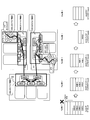
図23に示すように、BSIDをエリア単位で割り当てる場合、ABR11、ASBR21、ABR23がBSIDを展開するアンカーノードとなる。この場合、IngressでプッシュするSIDの数は少ないが、エリア数の増加に伴ってBSID数が増加するため、Ingressでのラベルプッシュ数が上限Uを上回る可能性がある。
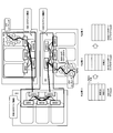
図24に示すように、本発明の実施例では、AS単位又はエリア単位という固定的な割り当てではなく、プッシュ可能なラベル数の上限を満たしつつ、BSIDを最小化するようなBSIDの展開に適したアンカーノードを選択することができる。ここでは、ABR11、ASBR21がBSIDを展開するアンカーノードとなる。BSIDのマージにより節約されたBSIDの数だけ、ラベルを指定可能になるため、ネットワーク全体で柔軟な経路制御が実現可能になる。
図25~図26は、3つのASで構成されるときの実施例の有効性を示す図である。ここでU=5であり、AS1のサブエリア(1)で3つのラベルを必要とすることを仮定する。
図25に示すようにBSIDをAS単位で割り当てる場合、ASBR32、ASBR21がBSIDを展開するアンカーノードとなる。この場合、BSID数は少ないがIngressプッシュするSIDの数が多くなり、Ingressでのラベルプッシュ数が上限Uを上回る可能性がある。また、AS内のNWが巨大な場合、AS内のルーティングだけでラベルプッシュ数が上限Uを超えてしまう可能性すらある。
図26に示すように、BSIDをエリア単位で割り当てる場合、ABR11、ASBR32、ASBR21、ABR23がBSIDを展開するアンカーノードとなる。この場合、IngressでプッシュするSIDの数は少ないが、エリア数の増加に伴ってBSID数が増加するため、Ingressでのラベルプッシュ数が上限Uを上回る可能性がある。
図27に示すように、本発明の実施例では、AS単位又はエリア単位という固定的な割り当てではなく、プッシュ可能なラベル数の上限を満たしつつ、BSIDを最小化するようなBSIDの展開に適したアンカーノードを選択することができる。ここでは、ABR11、ASBR21がBSIDを展開するアンカーノードとなる。BSIDのマージにより節約されたBSIDの数だけ、ラベルを指定可能になるため、ネットワーク全体で柔軟な経路制御が実現可能になる。
<ハードウェア構成例>
図28に、本発明の実施例に係るコントローラ100のハードウェア構成例を示す。コントローラ100は、CPU(Central Processing Unit)151等のプロセッサ、RAM(Random Access Memory)やROM(Read Only Memory)等のメモリ装置152、ハードディスク等の記憶装置153等から構成されたコンピュータでもよい。例えば、コントローラ100の機能及び処理は、記憶装置153又はメモリ装置152に格納されているデータやプログラムをCPU151が実行することによって実現される。また、コントローラ100へのデータの入力は、入出力インタフェース装置154から行われ、コントローラ100からのデータの出力は、入出力インタフェース装置154から行われてもよい。
図28に、本発明の実施例に係るコントローラ100のハードウェア構成例を示す。コントローラ100は、CPU(Central Processing Unit)151等のプロセッサ、RAM(Random Access Memory)やROM(Read Only Memory)等のメモリ装置152、ハードディスク等の記憶装置153等から構成されたコンピュータでもよい。例えば、コントローラ100の機能及び処理は、記憶装置153又はメモリ装置152に格納されているデータやプログラムをCPU151が実行することによって実現される。また、コントローラ100へのデータの入力は、入出力インタフェース装置154から行われ、コントローラ100からのデータの出力は、入出力インタフェース装置154から行われてもよい。
<補足>
説明の便宜上、本発明の実施例に係る装置は機能的なブロック図を用いて説明しているが、本発明の実施例に係る装置は、ハードウェア、ソフトウェア又はそれらの組み合わせで実現されてもよい。例えば、本発明の実施例は、コンピュータに対して本発明の実施例に係る装置の機能を実現させるプログラム、コンピュータに対して本発明の実施例に係る方法の各手順を実行させるプログラム等により、実現されてもよい。また、各機能部が必要に応じて組み合わせて使用されてもよい。また、本発明の実施例に係る方法は、実施例に示す順序と異なる順序で実施されてもよい。
説明の便宜上、本発明の実施例に係る装置は機能的なブロック図を用いて説明しているが、本発明の実施例に係る装置は、ハードウェア、ソフトウェア又はそれらの組み合わせで実現されてもよい。例えば、本発明の実施例は、コンピュータに対して本発明の実施例に係る装置の機能を実現させるプログラム、コンピュータに対して本発明の実施例に係る方法の各手順を実行させるプログラム等により、実現されてもよい。また、各機能部が必要に応じて組み合わせて使用されてもよい。また、本発明の実施例に係る方法は、実施例に示す順序と異なる順序で実施されてもよい。
以上、SRにおいてパケットにスタックされるラベル数を削減するための手法について説明したが、本発明は、上記の実施例に限定されることなく、特許請求の範囲内において、種々の変更・応用が可能である。
100 コントローラ
110 NW情報取得装置
111 通信部
112 情報管理部
113 リンクステート情報演算部
114 データ送信情報テーブル
115 リンクステート情報テーブル
116 経路情報テーブル
120 SR経路作成装置
121 通信部
122 SR経路作成部
123 ポリシー情報テーブル
130 経路圧縮装置
131 通信部
132 アンカーノード情報抽出部
133 圧縮演算部
134 アンカーノード情報テーブル
140 SRポリシー配信装置
141 通信部
142 情報管理部
143 圧縮経路管理テーブル
110 NW情報取得装置
111 通信部
112 情報管理部
113 リンクステート情報演算部
114 データ送信情報テーブル
115 リンクステート情報テーブル
116 経路情報テーブル
120 SR経路作成装置
121 通信部
122 SR経路作成部
123 ポリシー情報テーブル
130 経路圧縮装置
131 通信部
132 アンカーノード情報抽出部
133 圧縮演算部
134 アンカーノード情報テーブル
140 SRポリシー配信装置
141 通信部
142 情報管理部
143 圧縮経路管理テーブル
Claims (8)
- 複数の通信装置で構成されたネットワークにおいて、当該複数の通信装置のうち予め指定された1つ以上のアンカーノードを制御する制御装置であって、
入力された要求条件に基づき、経由すべき通信装置又はリンクのラベルを含む経路情報を作成する経路作成部と、
前記経路情報に含まれるラベルをアンカーノード単位で分割し、前記経路情報に基づいて決定される通信装置の処理限界を超えないように、前記経路情報に含まれるラベルのうち少なくとも一部を、前記経路情報に基づいて決定される通信装置のうち少なくとも1つのアンカーノードにおいて展開できる圧縮ラベルに圧縮する経路圧縮部と、
前記圧縮ラベルを展開するための情報を前記少なくとも1つのアンカーノードに配信する配信部と、
を有する制御装置。 - 前記経路圧縮部は、前記経路情報に基づいて決定される通信装置の処理限界を超えない範囲で圧縮ラベル同士をマージし、
前記配信部は、前記マージした圧縮ラベルを展開するための情報を配信する、請求項1に記載の制御装置。 - 前記経路圧縮部は、前記経路情報の中の複数のラベルを、当該複数のラベルで指定される部分経路と等価な、当該部分経路の端点となる通信装置を示すラベルに置き換える、請求項1又は2に記載の制御装置。
- 前記経路圧縮部は、前記経路情報に基づいて決定される通信装置の処理限界を超えないように、いずれかのアンカーノードで経路を終端し、当該経路を終端したアンカーノードを経路の始点とする新たな経路情報を作成し、
前記配信部は、前記新たな経路情報を、前記経路を終端したアンカーノードに配信する、請求項1乃至3のうちいずれか1項に記載の制御装置。 - 前記1つ以上のアンカーノードからネットワーク情報を取得し、通信装置の処理限界を取得するネットワーク情報取得部を更に有する、請求項1乃至4のうちいずれか1項に記載の制御装置。
- 前記経路作成部は、前記取得されたネットワーク情報に更に基づいて、前記入力された要求条件を満たす経路情報を作成する、請求項5に記載の制御装置。
- 複数の通信装置で構成されたネットワークにおいて、当該複数の通信装置のうち予め指定された1つ以上のアンカーノードを制御する制御装置が実行する制御方法であって、
入力された要求条件に基づき、経由すべき通信装置又はリンクのラベルを含む経路情報を作成するステップと、
前記経路情報に含まれるラベルをアンカーノード単位で分割し、前記経路情報に基づいて決定される通信装置の処理限界を超えないように、前記経路情報に含まれるラベルのうち少なくとも一部を、前記経路情報に基づいて決定される通信装置のうち少なくとも1つのアンカーノードにおいて展開できる圧縮ラベルに圧縮するステップと、
前記圧縮ラベルを展開するための情報を前記少なくとも1つのアンカーノードに配信するステップと、
を有する制御方法。 - 請求項1乃至6のうちいずれか1項に記載の制御装置の各部としてコンピュータを機能させるためのプログラム。
Priority Applications (1)
| Application Number | Priority Date | Filing Date | Title |
|---|---|---|---|
| US17/427,841 US11968121B2 (en) | 2019-02-06 | 2020-01-31 | Control apparatus, control method and program |
Applications Claiming Priority (2)
| Application Number | Priority Date | Filing Date | Title |
|---|---|---|---|
| JP2019-020141 | 2019-02-06 | ||
| JP2019020141A JP7176428B2 (ja) | 2019-02-06 | 2019-02-06 | 制御装置、制御方法及びプログラム |
Publications (1)
| Publication Number | Publication Date |
|---|---|
| WO2020162361A1 true WO2020162361A1 (ja) | 2020-08-13 |
Family
ID=71947100
Family Applications (1)
| Application Number | Title | Priority Date | Filing Date |
|---|---|---|---|
| PCT/JP2020/003696 Ceased WO2020162361A1 (ja) | 2019-02-06 | 2020-01-31 | 制御装置、制御方法及びプログラム |
Country Status (3)
| Country | Link |
|---|---|
| US (1) | US11968121B2 (ja) |
| JP (1) | JP7176428B2 (ja) |
| WO (1) | WO2020162361A1 (ja) |
Cited By (1)
| Publication number | Priority date | Publication date | Assignee | Title |
|---|---|---|---|---|
| WO2022127936A1 (en) * | 2020-12-18 | 2022-06-23 | Huawei Technologies Co., Ltd. | Methods, apparatus and system for creating sr policy using path computation element protocol |
Families Citing this family (2)
| Publication number | Priority date | Publication date | Assignee | Title |
|---|---|---|---|---|
| CN115314563A (zh) * | 2020-01-20 | 2022-11-08 | 华为技术有限公司 | 一种消息生成方法、处理方法及装置 |
| WO2024116350A1 (ja) * | 2022-11-30 | 2024-06-06 | 日本電信電話株式会社 | 経路算出装置、プログラムおよび経路算出方法 |
Citations (4)
| Publication number | Priority date | Publication date | Assignee | Title |
|---|---|---|---|---|
| US20170064717A1 (en) * | 2015-08-31 | 2017-03-02 | Cisco Technology, Inc. | Segment routing conduit |
| WO2017198319A1 (en) * | 2016-05-20 | 2017-11-23 | Telefonaktiebolaget Lm Ericsson (Publ) | Method and apparatus for segment routing and rsvp-te routing in transport sdn networks |
| WO2018033769A1 (en) * | 2016-08-15 | 2018-02-22 | Telefonaktiebolaget Lm Ericsson (Publ) | Segment routing based on maximum segment identifier depth |
| CN109218189A (zh) * | 2017-07-03 | 2019-01-15 | 中兴通讯股份有限公司 | 跨域的路径的标识信息的确定方法、装置及存储介质 |
Family Cites Families (2)
| Publication number | Priority date | Publication date | Assignee | Title |
|---|---|---|---|---|
| US8837292B2 (en) * | 2010-09-21 | 2014-09-16 | Telefonaktiebolaget L M Ericsson (Publ) | Relayed CSPF computation for multiple areas and multiple autonomous systems |
| WO2016204662A1 (en) * | 2015-06-16 | 2016-12-22 | Telefonaktiebolaget Lm Ericsson (Publ) | Apparatus and method for segment routing |
-
2019
- 2019-02-06 JP JP2019020141A patent/JP7176428B2/ja active Active
-
2020
- 2020-01-31 WO PCT/JP2020/003696 patent/WO2020162361A1/ja not_active Ceased
- 2020-01-31 US US17/427,841 patent/US11968121B2/en active Active
Patent Citations (4)
| Publication number | Priority date | Publication date | Assignee | Title |
|---|---|---|---|---|
| US20170064717A1 (en) * | 2015-08-31 | 2017-03-02 | Cisco Technology, Inc. | Segment routing conduit |
| WO2017198319A1 (en) * | 2016-05-20 | 2017-11-23 | Telefonaktiebolaget Lm Ericsson (Publ) | Method and apparatus for segment routing and rsvp-te routing in transport sdn networks |
| WO2018033769A1 (en) * | 2016-08-15 | 2018-02-22 | Telefonaktiebolaget Lm Ericsson (Publ) | Segment routing based on maximum segment identifier depth |
| CN109218189A (zh) * | 2017-07-03 | 2019-01-15 | 中兴通讯股份有限公司 | 跨域的路径的标识信息的确定方法、装置及存储介质 |
Non-Patent Citations (1)
| Title |
|---|
| TOGARI, YUKIHIRO: "A study of label pushing reduction mechanism for SR-MPLS", 2 PROCEEDINGS OF THE 2019 IEICE GENERAL CONFERENCE, 5 March 2019 (2019-03-05), pages 82 * |
Cited By (1)
| Publication number | Priority date | Publication date | Assignee | Title |
|---|---|---|---|---|
| WO2022127936A1 (en) * | 2020-12-18 | 2022-06-23 | Huawei Technologies Co., Ltd. | Methods, apparatus and system for creating sr policy using path computation element protocol |
Also Published As
| Publication number | Publication date |
|---|---|
| JP7176428B2 (ja) | 2022-11-22 |
| US20220131796A1 (en) | 2022-04-28 |
| US11968121B2 (en) | 2024-04-23 |
| JP2020127183A (ja) | 2020-08-20 |
Similar Documents
| Publication | Publication Date | Title |
|---|---|---|
| JP6470838B2 (ja) | ソフトウェア定義型ネットワーキングにおけるデータ転送方法、装置、およびシステム | |
| JP4374307B2 (ja) | ラベルスイッチパスの経路制御方法 | |
| CN115733791B (zh) | 对支持分段路由的多路径网络的优化 | |
| EP3459214B1 (en) | Method and apparatus for segment routing and rsvp-te routing in transport sdn networks | |
| JP6007799B2 (ja) | 集中管理型網制御システム | |
| CN105871722A (zh) | 标签构造以及标签报文转发方法及装置 | |
| CN106063195A (zh) | 具有单独控制设备和转发设备的网络中的控制设备发现 | |
| JP4899643B2 (ja) | ネットワーク構成装置 | |
| CN105594167A (zh) | 转发报文的方法、控制器、转发设备和网络系统 | |
| EP3310010B1 (en) | Method for allocating global label, method for acquiring global label and related device | |
| JP6323547B2 (ja) | 通信システム、制御装置、通信制御方法、および、プログラム | |
| JP6042838B2 (ja) | 管理システム、管理サーバ、および管理方法 | |
| JP7176428B2 (ja) | 制御装置、制御方法及びプログラム | |
| JP5493965B2 (ja) | 帯域制御システム、帯域制御装置、帯域制御方法および帯域制御プログラム | |
| WO2016186861A1 (en) | Method and apparatus for self-tuned adaptive routing | |
| JPWO2004086697A1 (ja) | 複数リンクを有するノード装置および複数リンクへのユーザ帯域割り当て方法 | |
| JP6647179B2 (ja) | 経路変換制御装置、経路変換制御方法および経路変換制御プログラム | |
| US7296087B1 (en) | Dynamic allocation of shared network resources between connection-oriented and connectionless traffic | |
| JP2004159112A (ja) | 通信制御システム、通信制御方法、これらに用いて好適なルーティング制御装置及びルータ装置 | |
| JP4603519B2 (ja) | 経路計算方法、経路計算プログラム、経路計算装置およびノード | |
| JP2007074055A (ja) | 動的制御用ネットワークリソース制御方法および動的制御用ネットワークリソース制御装置 | |
| EP1185029B1 (en) | Service deployment in data networks | |
| JP4144802B2 (ja) | Ipアドレス設定方法及びルータ | |
| CN116032817B (zh) | BGP-intent路由的接收方法和BGP-intent路由的通告方法 | |
| JP2004221930A (ja) | 分散型ネットワークを管理する管理範囲決定方法、装置及びプログラム |
Legal Events
| Date | Code | Title | Description |
|---|---|---|---|
| 121 | Ep: the epo has been informed by wipo that ep was designated in this application |
Ref document number: 20752712 Country of ref document: EP Kind code of ref document: A1 |
|
| NENP | Non-entry into the national phase |
Ref country code: DE |
|
| 122 | Ep: pct application non-entry in european phase |
Ref document number: 20752712 Country of ref document: EP Kind code of ref document: A1 |