WO2020162333A1 - Armature - Google Patents
Armature Download PDFInfo
- Publication number
- WO2020162333A1 WO2020162333A1 PCT/JP2020/003557 JP2020003557W WO2020162333A1 WO 2020162333 A1 WO2020162333 A1 WO 2020162333A1 JP 2020003557 W JP2020003557 W JP 2020003557W WO 2020162333 A1 WO2020162333 A1 WO 2020162333A1
- Authority
- WO
- WIPO (PCT)
- Prior art keywords
- leg
- insulating layer
- portions
- crossover
- pair
- Prior art date
Links
Images


Classifications
-
- H—ELECTRICITY
- H02—GENERATION; CONVERSION OR DISTRIBUTION OF ELECTRIC POWER
- H02K—DYNAMO-ELECTRIC MACHINES
- H02K3/00—Details of windings
- H02K3/04—Windings characterised by the conductor shape, form or construction, e.g. with bar conductors
- H02K3/12—Windings characterised by the conductor shape, form or construction, e.g. with bar conductors arranged in slots
-
- H—ELECTRICITY
- H02—GENERATION; CONVERSION OR DISTRIBUTION OF ELECTRIC POWER
- H02K—DYNAMO-ELECTRIC MACHINES
- H02K3/00—Details of windings
- H02K3/32—Windings characterised by the shape, form or construction of the insulation
- H02K3/34—Windings characterised by the shape, form or construction of the insulation between conductors or between conductor and core, e.g. slot insulation
- H02K3/345—Windings characterised by the shape, form or construction of the insulation between conductors or between conductor and core, e.g. slot insulation between conductor and core, e.g. slot insulation
-
- H—ELECTRICITY
- H02—GENERATION; CONVERSION OR DISTRIBUTION OF ELECTRIC POWER
- H02K—DYNAMO-ELECTRIC MACHINES
- H02K3/00—Details of windings
- H02K3/32—Windings characterised by the shape, form or construction of the insulation
- H02K3/38—Windings characterised by the shape, form or construction of the insulation around winding heads, equalising connectors, or connections thereto
-
- Y—GENERAL TAGGING OF NEW TECHNOLOGICAL DEVELOPMENTS; GENERAL TAGGING OF CROSS-SECTIONAL TECHNOLOGIES SPANNING OVER SEVERAL SECTIONS OF THE IPC; TECHNICAL SUBJECTS COVERED BY FORMER USPC CROSS-REFERENCE ART COLLECTIONS [XRACs] AND DIGESTS
- Y02—TECHNOLOGIES OR APPLICATIONS FOR MITIGATION OR ADAPTATION AGAINST CLIMATE CHANGE
- Y02T—CLIMATE CHANGE MITIGATION TECHNOLOGIES RELATED TO TRANSPORTATION
- Y02T10/00—Road transport of goods or passengers
- Y02T10/60—Other road transportation technologies with climate change mitigation effect
- Y02T10/64—Electric machine technologies in electromobility
Definitions
- the present invention relates to an armature.
- an armature provided with a segment conductor provided with a transition portion is known.
- Such an armature is disclosed in, for example, Japanese Patent Laid-Open No. 2004-64989.
- the above-mentioned Japanese Patent Laid-Open No. 2004-64989 discloses a stator including a stator core provided with a plurality of slots.
- a segment conductor having a U shape is inserted into the slot of the stator core.
- the segment conductor includes a pair of linearly extending slot insertion portions and an insertion-side end portion connecting one ends of the pair of slot insertion portions. Each of the pair of slot insertion portions is inserted into different slots. Further, the insertion-side end portion is provided so as to project from one axial side of the slot. Further, the segment conductor has a pair of joining side end portions integrally provided with the slot insertion portion at the other end of the slot insertion portion.
- Each of the pair of joining-side end portions is provided so as to project from the other axial side of the slot.
- the pair of joining-side end portions are bent so as to come close to each other in a state of protruding from the other axial side of the slot, and then the respective end portions are joined.
- each of the plurality of joining-side end portions is arranged adjacent to the joining-side end portions (insertion-side end portions) of different phases, and each of the plurality of slot insertion portions is arranged. May be arranged so as to be adjacent to the slot insertion portions having the same phase in each slot.
- the joint side end portion (insertion side end portion) in which different phases are arranged adjacent to each other has higher insulation performance than the slot insertion portion in which the same phase is arranged adjacent to each other. Required. Therefore, as described in Japanese Patent Laid-Open No.
- the insertion-side end portion (bonding-side end portion) is subjected to an insulating treatment such as forming a powder coating film on each of the insertion-side end portion and the joining-side end portion. It is conceivable that the insulation performance of the part) is higher than the slot insertion part.
- the transition portion (formed on the transition portion is formed. Insulation layer, etc.) may be damaged.
- the crossover part (such as the insulating layer formed on the crossover part) may be damaged due to the joining process. is there. That is, in the conventional armature as described in JP 2004-64989 A, when the segment conductor is arranged on the stator core along the axial direction, the insulation-treated crossover portion is damaged (crossover). There is a problem that the insulating layer and the like formed on the portion are damaged).
- the present invention has been made in order to solve the above problems, and one object of the present invention is to make the connecting portions more sensible when arranging the segment conductors in the armature core along the axial direction.
- An object of the present invention is to provide an armature capable of preventing damage to a crossover portion subjected to an insulation treatment while surely insulating.
- an armature in order to achieve the above object, includes an armature core provided with a plurality of slots extending in the axial direction, and a pair extending in one axial direction along the axial direction.
- a plurality of first segment conductors including a first leg portion and a first crossover portion that connects the end portions of the pair of first leg portions on the other side in the axial direction, and an axial direction along the axial direction.
- a plurality of second segment conductors of a plurality of phases including a pair of second leg portions extending to the other side and a second crossover portion connecting end portions of the pair of second leg portions on one side in the axial direction, and a first leg An end portion on one side in the axial direction of the portion, and an end portion on the other side in the axial direction of the second leg portion are joined inside one slot or on the outside in the axial direction of one slot; And a coil part including a first coil part including a first coil part, and a first leg part of each of the plurality of first segment conductors is arranged so as to be adjacent to the first leg parts of the same phase, and the first leg part of each of the plurality of second segment conductors is arranged.
- the two legs are arranged so as to be adjacent to the second legs that are in phase with each other, and the first transition portions of each of the plurality of first segment conductors are adjacent to the first transition portions that have different phases.
- the second crossover portion of each of the plurality of second segment conductors is arranged so as to be adjacent to the second crossover portions of different phases, and the first crossover portion and the second crossover portion include the first leg portion.
- the voltage value that can be insulated is higher than that of the second leg.
- the term “joined portion” has a broad meaning including not only a portion joined with a bonding agent but also a portion only contacted with no bonding agent.
- the voltage value at which the first crossover portion and the second crossover portion can be insulated is higher than that of the first leg portion and the second leg portion. It is possible to more reliably insulate each of the first transition part and the second transition part.
- the armature includes the first segment conductor and the second segment conductor as described above. And the 1st leg part of the 1st segment conductor and the 2nd leg part of the 2nd segment conductor are joined. That is, before joining the first leg portion and the second leg portion, the first segment conductor and the second segment conductor are provided separately (separated) from each other. In this case, the first segment conductor is moved to one side in the axial direction (the side where the first leg portion is provided with respect to the first crossover portion), and the second segment conductor is moved to the other side in the axial direction (the first side).
- the first leg and the second leg are arranged so as to be close to each other and are joined to each other by moving the first leg and the second leg with respect to the crossover (in the direction in which the second leg is provided). Accordingly, the first leg portion and the second leg portion can be brought close to each other and can be joined to each other without inserting the first bridging portion and the second bridging portion into the slots along the axial direction. .. As a result, the crossover part does not pass through the slot, so the crossover part that has been subjected to insulation treatment (formation of insulating film and placement of insulating members, etc.) to improve the insulation performance (voltage value that can be insulated) is damaged. It is possible to prevent (the insulating coating and the insulating member from being damaged).
- the first transitional portions are previously joined to each other.
- the segment conductors can be placed in the slots in the assembled state. That is, it is not necessary to join the first crossover portions (second crossover portions) by a joining process such as welding after the segment conductors are arranged in the slots. Accordingly, it is possible to prevent the bridging portion from being damaged (the insulating coating and the insulating member being damaged) due to the joining process.
- the crossovers can be more reliably insulated from each other and the crossovers subjected to the insulation treatment can be prevented from being damaged. be able to.
- An armature according to a second aspect of the present invention includes an armature core provided with a plurality of slots extending in the axial direction, a pair of first leg portions extending in the axial direction along one side in the axial direction, and a pair of paired legs.
- a plurality of first segment conductors of a plurality of phases including a first crossover portion connecting the ends of the first leg portions on the other side in the axial direction, and a pair of second segment conductors extending along the axial direction to the other side in the axial direction.
- a plurality of second segment conductors of a plurality of phases including a leg portion and a second crossover portion connecting end portions of the pair of second leg portions on one side in the axial direction, and one of the first leg portions on the one side in the axial direction.
- a coil portion including an end portion and a joint portion in which an end portion on the other side in the axial direction of the second leg portion is joined inside one slot or outside in the axial direction of the one slot.
- the first leg side insulating layer is provided on each of the pair of first legs, and the second leg side insulating layer is provided on each of the pair of second legs.
- a first transition portion-side insulating layer having a thickness larger than that of the first leg portion-side insulating layer is provided.
- a second thicker portion than the second leg side insulating layer is provided in at least a portion of the second crossover portion where the second crossover portions of different phases are arranged adjacent to each other.
- An insulating layer on the transition side is provided.
- At least a portion of the first transition portion where the first transition portions of different phases are arranged adjacent to each other is A first crossover portion side insulating layer having a larger thickness than the leg side insulating layer is provided, and at least second crossover portions of different phases of the second crossover portions are arranged adjacent to each other.
- a second crossover-side insulating layer having a thickness larger than that of the second leg-side insulating layer is provided in the portion. This makes it possible to insulate each of the first and second transition parts more reliably.
- the armature includes the first segment conductor and the second segment conductor as described above. And the 1st leg part of the 1st segment conductor and the 2nd leg part of the 2nd segment conductor are joined.
- the first segment conductor and the second segment conductor are provided separately (separated) from each other. In this case, the first segment conductor is moved to one side in the axial direction (the side where the first leg portion is provided with respect to the first crossover portion), and the second segment conductor is moved to the other side in the axial direction (the first side).
- the first leg and the second leg are arranged so as to be close to each other and are joined to each other by moving the first leg and the second leg with respect to the crossover (in the direction in which the second leg is provided). Accordingly, the first leg portion and the second leg portion can be brought close to each other and can be joined to each other without inserting the first bridging portion and the second bridging portion into the slots along the axial direction. .. As a result, since the transition portion does not pass through the slot, it is possible to prevent the transition portion from being damaged (the first transition portion side insulating layer and the second transition portion side insulating layer are damaged).
- the first transitional portions are previously joined to each other.
- the segment conductors can be placed in the slots in the assembled state. That is, it is not necessary to join the first crossover portions (second crossover portions) by a joining process such as welding after the segment conductors are arranged in the slots. This can prevent the bridging portion from being damaged (the first bridging portion-side insulating layer and the second bridging portion-side insulating layer being damaged) due to the bonding process.
- the crossovers can be more reliably insulated from each other, and the crossovers are damaged (the first crossover side insulating layer and the second crossover layer). It is possible to prevent the insulating layer on the transition side from being damaged.
- first leg portion and the second leg portion can be brought close to each other without inserting each of the first crossover portion and the second crossover portion into the slot, so that it is necessary to insert the coil portion from the inside in the radial direction. Absent. As a result, it is possible to prevent the insulating layer of the transition portion from being damaged by the pressure applied from the inside in the radial direction during the insertion from the inside in the radial direction.
- By moving each of the first segment conductor and the second segment conductor in the axial direction a plurality of circumferentially divided armature cores are used and the divided armature cores are moved in the radial direction. , It is not necessary to place the leg in the slot. As a result, it is possible to prevent deterioration of the armature core loss (such as iron loss due to an increase in magnetic resistance) as compared with the case where the armature core is divided.
- first leg portion and the second leg portion can be brought close to each other without inserting the first transition portion and the second transition portion into the slot, it is necessary to increase the area of the slot in plan view. Absent. As a result, it is possible to prevent the physique of the armature core from increasing, and it is possible to prevent the loss of the armature from deteriorating.
- the crossovers can be more reliably insulated from each other, and the crossovers that have been subjected to the insulation treatment are also provided. Can be prevented from being damaged.
- FIG. 6 is a plan view showing a configuration of a stator (rotary electric machine) according to the first and second embodiments.
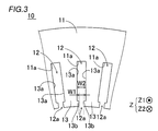
- FIG. 3 is a perspective view showing the configuration of the stator according to the first embodiment.
- FIG. 6 is a partially enlarged plan view showing a configuration of a stator core according to the first and second embodiments. It is a partial expanded sectional view showing composition of a core leg insulation member and a junction insulation member by a 1st embodiment. It is a circuit diagram showing a wire connection structure of a coil unit according to the first embodiment. It is a front view showing the composition of the 1st conductor by a 1st embodiment. It is a front view showing the composition of the 2nd conductor by a 1st embodiment.
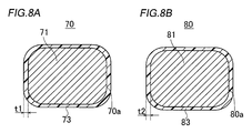
- FIG. 8A is a cross-sectional view of the first leg portion.
- FIG. 8B is a cross-sectional view of the second leg portion.
- FIG. 9A is a cross-sectional view of the first crossover portion.
- FIG. 9B is a cross-sectional view of the second crossover portion.
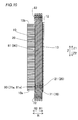
- FIG. 2 is a sectional view taken along the line 1000-1000 in FIG. 1.
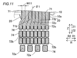
- FIG. 11 is a partially enlarged view of the vicinity of the first crossover portion of FIG. 10.
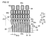
- FIG. 11 is a partially enlarged view of the vicinity of the second crossover portion of FIG. 10.
- FIG. 11 is a partially enlarged view of the vicinity of the second crossover portion of FIG. 10.
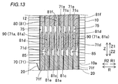
- FIG. 11 is a partially enlarged view of the vicinity of the joint portion of FIG. 10. It is a sectional view showing composition of a junction insulation member by a 1st embodiment. It is a perspective view showing the composition of the junction insulation member by a 1st embodiment.
- FIG. 3 is an exploded perspective view of a stator core, a core leg insulating member, and a joint insulating member according to the first embodiment.
- FIG. 6 is a flowchart for explaining the manufacturing method of the stator according to the first embodiment. It is a figure for demonstrating the structure of the crossover part by 1st Embodiment.
- FIG. 18A is a view of the first segment conductor arranged in the slot as viewed from the inside in the radial direction.
- FIG. 18A is a view of the first segment conductor arranged in the slot as viewed from the inside in the radial direction.
- FIG. 18B is a view of the second segment conductor arranged in the slot as viewed from the inside in the radial direction.
- 18C is a partially enlarged plan view of the vicinity of the transition portion.
- FIG. 6 is an exploded perspective view of a stator according to a second embodiment.
- FIG. 7 is a sectional view of a segment conductor according to a second embodiment.
- FIG. 9 is a cross-sectional view of the inside of the slot according to the second embodiment along the radial direction.
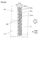
- FIG. 22 is a partially enlarged view of the vicinity of the contact portion of FIG. 21. It is sectional drawing which shows the structure of the insulating member by 2nd Embodiment.
- FIG. 9 is a partially enlarged view of the vicinity of a joint portion of a stator according to a first modified example of the first embodiment.
- FIG. 11 is a partially enlarged view of the vicinity of a joint portion of a stator according to a second modified example of the first embodiment.
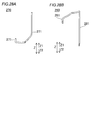
- FIG. 28A is a perspective view of the first conductor as viewed from the outside in the radial direction.
- FIG. 28B is a perspective view of the second conductor as viewed from the outside in the radial direction.
- stator 100 The structure of the stator 100 according to the present embodiment will be described with reference to FIGS. 1 to 17.
- the stator 100 has an annular shape centered on the central axis C.
- the stator 100 is an example of the “armature” in the claims.
- the “axial direction (axial direction)” means the direction (Z direction) along the central axis C of the stator 100 (rotational axis of the rotor 101) as shown in FIG.
- the one side in the axial direction means the Z1 direction side
- the other side in the axial direction means the Z2 direction side.
- the “circumferential direction” means the circumferential direction (A1 direction, A2 direction) of the stator 100.
- the “radial direction” means the radial direction (R direction) of the stator 100.
- “radially inward” means a direction (R1 direction) toward the central axis C of the stator 100 along the radial direction.
- “radially outside” means a direction (R2 direction) outward of the stator 100 along the radial direction.
- the stator 100 together with the rotor 101, constitutes a part of the rotating electric machine 102.
- the rotary electric machine 102 is configured as, for example, a motor, a generator, or a motor/generator.
- the stator 100 is arranged radially outside the rotor 101 in which a permanent magnet (not shown) is provided. That is, in the present embodiment, the stator 100 constitutes a part of the inner rotor type rotating electrical machine 102.
- the stator 100 includes a stator core 10, a sheet-shaped core leg insulating member 20, and a coil portion 30.
- the core leg insulating member 20 is provided between the slot 12 and the coil portion 30 to insulate the slot 12 (see FIG. 3) and the coil portion 30 (the first leg portion 71 and the second leg portion 81 described later) from each other. It is arranged. That is, the core leg insulating member 20 is inserted into the slot 12.
- the core leg insulating member 20 is provided separately from an insulating layer 73 (see FIG. 8A) described below and an insulating layer 83 (see FIG. 8B) described below.
- the stator core 10 is an example of the "armature core" in the claims.
- the coil unit 30 also includes a first coil assembly 30a (anti-lead side coil) and a second coil assembly 30b (lead side coil). Further, the coil portion 30 is composed of a plurality of segment conductors 40 (see FIG. 4). Further, the stator 100 includes a sheet-shaped joint insulation member 21 (see FIG. 4) provided separately from the core leg insulation member 20.
- the stator core 10 has a cylindrical shape with a central axis C (see FIG. 1) as a central axis. Further, stator core 10 is formed, for example, by stacking a plurality of electromagnetic steel plates (for example, silicon steel plates) in the axial direction. As shown in FIG. 3, the stator core 10 is provided with a back yoke 11 having an annular shape when viewed in the axial direction, and a plurality of slots 12 provided inside the back yoke 11 in the radial direction and extending in the axial direction. .. The stator core 10 is provided with a plurality of teeth 13 on both sides of the slot 12 in the circumferential direction.
- the slot 12 is a portion surrounded by the wall portion 11a of the back yoke 11 provided on the radially outer side and the circumferential side surfaces 13a of the two teeth 13.
- the slot 12 is provided with an opening 12a that opens radially inward.
- the slots 12 are open on both sides in the axial direction.
- the tooth 13 is formed so as to protrude radially inward from the back yoke 11, and a convex portion 13 b forming an opening 12 a of the slot 12 is formed at a tip end portion radially inward.
- the opening 12a has an opening width W1 in the circumferential direction.
- the opening width W1 corresponds to the distance between the tips of the protrusions 13b of the teeth 13.
- the width W2 of the portion of the slot 12 where the coil portion 30 is arranged is larger than the opening width W1. That is, the slot 12 is configured as a semi-open type slot.
- the width W2 corresponds to the distance between the circumferential side surfaces 13a of the teeth 13 arranged on both sides of the slot 12 in the circumferential direction.
- the width W2 of the slot 12 is substantially constant in the radial direction.
- the coil portion 30 is composed of a flat conductor wire.
- the coil portion 30 is made of copper or aluminum.
- the coil unit 30 includes a first coil assembly 30a provided on the other side in the axial direction (Z2 direction side) and a second coil provided on the one side in the axial direction (Z1 direction side).
- the assembly 30b and the assembly 30b are combined in the axial direction and joined together.
- the first coil assembly 30a and the second coil assembly 30b are each formed in an annular shape centered on the same central axis C (see FIG. 1) as the stator core 10.
- the coil portion 30 is formed by joining the later-described first leg portions 71 and second leg portions 81 of the plurality of segment conductors 40 at the joint portions 90. ing.
- the coil unit 30 is configured, for example, as a wave winding coil. Moreover, the coil part 30 is comprised as a coil of 8 turns. That is, the coil portion 30 is configured such that eight segment conductors 40 are arranged in parallel in the slot 12 in the radial direction.
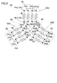
- the coil unit 30 is configured to generate magnetic flux by being supplied with three-phase AC power from a power supply unit (not shown). Specifically, the coil portions 30 are connected (wired) by three-phase Y wires. That is, the coil unit 30 includes a U-phase coil unit 30U, a V-phase coil unit 30V, and a W-phase coil unit 30W. The coil portion 30 is provided with a plurality (for example, two) of neutral points N. Specifically, the coil unit 30 is connected in four parallel lines (star connection). That is, the U-phase coil portion 30U is provided with four neutral point connection ends NtU and four power line connection ends PtU.
- the V-phase coil portion 30V is provided with four neutral point connection ends NtV and four power line connection ends PtV.
- the W-phase coil portion 30W is provided with four neutral point connection ends NtW and four power line connection ends PtW.
- the first coil assembly 30a includes a plurality of first segment conductors 70 (hereinafter, referred to as “first conductors 70”) as the segment conductors 40.
- first conductors 70 first segment conductors 70
- the first coil assembly 30a is configured by combining only the plurality of first conductors 70.
- the second coil assembly 30b includes a plurality of (eg, three) power segment conductors 50 as segment conductors 40 (hereinafter referred to as “power conductors 50”) and a plurality of segment conductors 40 (eg, two). ) A neutral point segment conductor 60 (hereinafter referred to as “neutral point conductor 60”) and a conductor different from the power conductor 50 and the neutral point conductor 60 among the plurality of segment conductors 40 (general segment conductor 40). ), and includes the second segment conductor 80 (hereinafter, referred to as “second conductor 80”) that constitutes the coil portion 30. That is, all of the power conductor 50 and the neutral point conductor 60 provided in the stator 100 are provided in the second coil assembly 30b.
- the coil portion 30 includes a plurality of first conductors 70 including a pair of first leg portions 71 extending to one axial side (Z1 direction side) of the stator core 10.
- the multiple first conductors 70 include multiple-phase first conductors 70.
- the plurality of first conductors 70 include a U-phase first conductor 70, a V-phase first conductor 70, and a W-phase first conductor 70.
- each of the plurality of first conductors 70 is arranged on the other side (Z2 direction side) of the stator core 10 in the axial direction.
- the first leg portion 71 of each of the plurality of first conductors 70 has a length L1 in the axial direction.
- the coil portion 30 includes a plurality of second conductors 80 including a pair of second leg portions 81 extending to the other axial side (Z2 direction side) of the stator core 10.
- the multiple second conductors 80 include multiple phase second conductors 80.
- the plurality of second conductors 80 include a U-phase second conductor 80, a V-phase second conductor 80, and a W-phase second conductor 80.
- each of the plurality of second conductors 80 is arranged on one side (Z1 direction side) in the axial direction of the stator core 10.
- each of the plurality of second conductors 80 is arranged so as to axially face the plurality of first conductors 70.
- the second leg portion 81 of each of the plurality of second conductors 80 has a length L2 in the axial direction. The length L2 of the second leg portion 81 is longer than the length L1 of the first leg portion 71.
- the coil portion 30 is formed by joining the first conductor 70 and the second conductor 80, which are divided into two in the axial direction. Specifically, in the coil portion 30, one end portion 71 a on the one axial side of the first leg portion 71 and the other end portion 81 a on the other axial side of the second leg portion 81 are within one slot 12.
- the joint portion 90 (see FIG. 10) joined together is included.
- the second conductor 80 is the segment conductor 40 other than the power conductor 50 and the neutral point conductor 60 of the segment conductor 40 that constitutes the second coil assembly 30b.
- the end portion 71a is a portion including a first surface arrangement portion 71d described later.
- the end portion 81a is a portion including a second surface arrangement portion 81d described later.
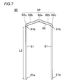
- each of the multiple-phase first conductors 70 has a first crossover portion 72 that connects the other end portions 71b of the pair of first leg portions 71 on the other axial side (Z2 direction side). Including.
- Each of the multiple-phase first conductors 70 has a U-shape (approximately U) when viewed in the radial direction by the pair of first leg portions 71 arranged in the different slots 12 being connected by the first transition portions 72. (Shaped).
- the coil pitch of the first conductor 70 is 6. That is, the pair of first leg portions 71 are arranged at positions different in the circumferential direction by six slots 12.
- the first leg portion 71 means the portion of the first conductor 70 that extends linearly in the axial direction. Specifically, the first leg portion 71 means a portion from the end portion 71b to a tip portion 71e of the first leg portion 71 described later. Further, the first crossover portion 72 means a portion of the first conductor 70 other than the first leg portion 71.
- the first transition part 72 has a bent shape that bends in the axial direction.
- the first crossover 72 has a first bent portion 72a that is bent at the center of the first crossover 72.
- the first crossover 72 has a pair of first skewed portions 72b linearly extending from the first bent portion 72a toward the pair of first legs 71 so as to intersect each other.
- the first bent portion 72a is formed in a crank shape that is bent in a stepwise manner by the width of one segment conductor 40 in the radial direction when viewed in the axial direction. That is, the radial width of the first bent portion 72a is twice the width of the single segment conductor 40. Note that "intersecting each other” means that the extension lines of the first skewed portions 72b intersect each other outside in the axial direction of the stator core 10 as viewed in the radial direction.
- the axial lengths L1 of the pair of first legs 71 are substantially equal to each other.
- the axial length L1 is smaller than the axial length L3 (see FIG. 2) of the stator core 10.
- the axial length L3 of the stator core 10 means the axial distance (interval) between the end faces 10a and 10b in the axial direction.
- each of the multiple-phase second conductors 80 has a second crossover that connects the end portions 81b of the pair of second leg portions 81 on one side (Z1 direction side) in the axial direction.
- the part 82 is included.
- Each of the plural-phase second conductors 80 is formed to have a U-shape by connecting the pair of second leg portions 81 arranged in the different slots 12 by the second connecting portion 82. ..
- the coil pitch of the second conductor 80 is 6. That is, the pair of second legs 81 are arranged at different positions in the circumferential direction by the six slots 12.
- the second leg portion 81 means a portion of the second conductor 80 that extends linearly in the axial direction. Specifically, the second leg portion 81 means a portion from the end portion 81b to a tip portion 81e of the second leg portion 81 described later.
- the second transition portion 82 means a portion of the second conductor 80 other than the second leg portion 81.
- the second transition part 82 has a bent shape that bends in the axial direction.
- the second bridging portion 82 has a second bent portion 82a that is bent at the center of the second bridging portion 82.
- the second crossover portion 82 has a pair of second skewed portions 82b that linearly extend from the second bent portion 82a toward the pair of second leg portions 81 so as to intersect each other.
- the second bent portion 82a is formed in a crank shape that is bent in a stepwise manner by the width of one segment conductor 40 in the radial direction when viewed in the axial direction. That is, the width of the second bent portion 82a in the radial direction is twice the width of one segment conductor 40.
- the axial lengths L2 of the pair of second legs 81 of the second conductor 80 are substantially equal to each other.
- the axial length L2 of the pair of second leg portions 81 of the second conductor 80 is larger than the axial length L1 of the pair of first leg portions 71 of the first conductor 70 (L2>L1).
- an insulating layer 73 is provided on each of the pair of first leg portions 71.
- the segment conductor 40 (the first conductor 70 and the second conductor 80) is configured as a flat conductor wire having a substantially rectangular cross section.
- An insulating layer 73 having a thickness t1 is provided on the conductor surface 70a of the first conductor 70.
- the thickness t1 of the insulating layer 73 is set to such an extent that the interphase insulating performance (insulation of the first leg portions 71) can be secured, for example. Note that, in FIG. 8A, for the sake of explanation, the magnitude relationship such as the thickness is emphasized, but the present invention is not limited to this example.
- the insulating layer 73 is an example of the "first leg-side insulating layer" in the claims.
- an insulating layer 83 is provided on each of the pair of second legs 81.
- the insulating layer 83 of the second conductor 80 is provided with the insulating layer 83 having a thickness t2.
- the thickness t2 of the insulating layer 83 is set, for example, to such an extent that the in-phase insulating performance (insulation between the second leg portions 81) can be secured. Note that, in FIG. 8B, for the sake of explanation, the magnitude relation of the thickness and the like is emphasized, but the present invention is not limited to this example.
- the thickness t2 of the insulating layer 83 is substantially equal to the thickness t1 of the insulating layer 73.
- the insulating layer 83 is an example of the “second leg side insulating layer” in the claims.
- first leg portions 71 are arranged in the radial direction of the stator core 10 within one slot 12 (see FIG. 10).
- second leg portions 81 are arranged in one slot 12 in the radial direction of stator core 10 (see FIG. 10 ).
- first crossover portions 72 are radially arranged (see FIG. 10) on the other axial side (Z2 direction side) in slot 12.
- second crossover portions 82 are arranged in a radial direction on one side (Z1 direction side) in the slot 12 (see FIG. 10).
- the first transition portions 72 of each of the plurality of first conductors 70 are arranged so as to be adjacent to the first transition portions 72 of different phases.
- U-phase, V-phase, and W-phase segment conductors are described as U, V, and W, respectively.
- the entire pair of first skewed portions 72b of the first crossover portion 72 are adjacent (in the radial direction and the axial direction) to the first skewed portions 72b of the first crossover portions 72 of different phases. (See FIG. 11).
- FIG. 18 illustrates only the first transition part 72, the second transition part 82 has the same configuration, and therefore the illustration thereof is omitted.
- the second transition portions 82 of each of the plurality of second conductors 80 are arranged so as to be adjacent to the second transition portions 82 of different phases. Specifically, of the second crossover portions 82, the entire pair of second skew portions 82b are adjacent (in the radial direction and the axial direction) to the second skew portions 82b of the second crossover portions 82 of different phases. (See FIG. 12).
- FIG. 18A illustrates a state in which four portions 72e are provided in each of the pair of linear portions 72b.
- FIG. 18B similarly to the first crossover portion 72, each of the pair of second oblique portions 82b is partially arranged on the surface 82d facing in the radial direction and has a second phase of a different phase. A portion 82e adjacent to the transition portion 82 is provided.
- this is arranged so that the second skewed portion 82b (first skewed portion 72b) is displaced from each other in the radial direction with the second bent portion 82a (first bent portion 72a) as a boundary. It is due to the fact that it is being done (1 lane change). As a result, the second skewed portions 82b (first skewed portions 72b) of different phases are arranged so as to be partially adjacent to each other in the radial direction.
- the pair of first leg portions 71 are arranged such that their radial positions are displaced from each other by the radial width W11 (see FIG. 11) of the first leg portions 71.
- the pair of second leg portions 81 are arranged such that their radial positions are displaced from each other by the radial width W12 (see FIG. 12) of the second leg portion 81.
- the pair of first skewed portions 72b are arranged such that their radial positions are displaced from each other by the radial width W11 of the first leg 71.
- the pair of second skewed portions 82b are arranged such that the radial positions thereof are displaced from each other by the radial width W12 of the second leg portion 81.
- the first crossover portions of different phases are provided on the surfaces 72d on both sides in the radial direction.
- the second crossover portions of different phases are provided on the faces 82d on both sides facing the radial direction.
- the first skewed portion 72b has a portion adjacent to the first skewed portion 72b of a different phase in the circumferential direction (axial direction) even on the surface 72f facing the circumferential direction (axial direction).
- U1, U2, V1, V2... are arranged from the left, so that U2 is adjacent to the first skewed portion 72b of V1 in the circumferential direction (axial direction).
- the second skewed portion 82b is also provided with a surface 82f having a portion adjacent to the second skewed portion 82b of a different phase in the circumferential direction (axial direction).
- the insulation performance of the first transition part 72 and the second transition part 82 is higher than the insulation performance of the first leg part 71 and the second leg part 81.
- the insulating layer 73 is present in at least a portion (that is, the first skewed portion 72b) of the first transition portions 72 in which the first transition portions 72 of different phases are arranged adjacent to each other.
- An insulating layer 74 having a larger thickness than that (see FIG. 8A) is provided.
- the insulating layer 74 is an example of the "first crossover-side insulating layer" in the claims.
- “high insulation performance” means that the voltage value at which insulation is possible is high.
- the insulating layer 74 includes a first base insulating layer 74a and a first additional insulating layer 74c.
- the first insulating base layer 74a is formed integrally with the insulating layer 73 (see FIG. 8A) and has a thickness t3 equal to the thickness t1 of the insulating layer 73.
- the first additional insulating layer 74c is provided on the surface 74b of the first base insulating layer 74a.
- the thickness t4 of the first additional insulating layer 74c is larger than the thickness t1 of the insulating layer 73 (thickness t3 of the first insulating base layer 74a).
- the thickness t4 of the first additional insulating layer 74c is about 1.5 times the thickness t1 of the insulating layer 73 (thickness t3 of the first base insulating layer 74a). In this case, the thickness (t3+t4) of the insulating layer 74 is about 2.5 times the thickness t1 of the insulating layer 73.
- Each of the first additional insulating layer 74c and the first base insulating layer 74a is formed of the same material as the insulating layer 73 (for example, an insulating material such as polyimide).
- At least a portion of the second transition portions 82 where the second transition portions 82 of different phases are arranged adjacent to each other that is, the second skew portion 82b.
- An insulating layer 84 having a larger thickness than the insulating layer 83 (see FIG. 8B) is provided.
- the insulating layer 84 is an example of the “second crossing portion side insulating layer” in the claims.
- the insulating layer 84 includes a second base insulating layer 84a and a second additional insulating layer 84c.
- the second insulating base layer 84a is formed integrally with the insulating layer 83 (see FIG. 8B) and has a thickness t5 equal to the thickness t2 of the insulating layer 83.
- the second additional insulating layer 84c is provided on the surface 84b of the second base insulating layer 84a.
- the thickness t6 of the second additional insulating layer 84c is larger than the thickness t2 of the insulating layer 83 (thickness t5 of the second base insulating layer 84a).
- the thickness t6 of the second additional insulating layer 84c is about 1.5 times the thickness t2 of the insulating layer 83 (thickness t5 of the second base insulating layer 84a). In this case, the thickness (t5+t6) of the insulating layer 84 is about 2.5 times the thickness t2 of the insulating layer 83.
- Each of the second additional insulating layer 84c and the second base insulating layer 84a is made of the same material as the insulating layer 83 (for example, an insulating material such as polyimide).
- the stator It is possible to make 100 compatible with high voltage.
- the insulating layer 74 (first additional insulating layer 74c) is provided on each of the first bent portion 72a and the pair of first skewed portions 72b. Specifically, the insulating layer 74 (first additional insulating layer 74c) is provided in a portion of the first transition portion 72 other than the first inclined portion 72c described later.
- the first additional insulating layer 74c of the insulating layer 74 provided on the first bent portion 72a and the first additional insulating layer 74c of the insulating layer 74 provided on each of the pair of first skewed portions 72b. are integrally provided.
- the first additional insulating layer 74c is a single insulating layer.
- the insulating layer 74 is an insulating layer which is not divided into a plurality of parts and is continuously formed in the first transition part 72.
- the insulating layer 74 is provided so as to circumferentially surround the first crossover portion 72 in a cross section (transverse cross section) orthogonal to the direction in which the first crossover portion 72 extends. .. That is, the insulating layer 74 has an annular shape that covers the first crossover portion 72 from the outside in the radial direction when the cross section (transverse cross section) is viewed.
- the insulating layer 84 (second additional insulating layer 84c) is provided on each of the second bent portion 82a and the pair of second skewed portions 82b. Specifically, the insulating layer 84 (second additional insulating layer 84c) is provided in a portion of the second transition portion 82 other than the second inclined portion 82c described later.
- the second additional insulating layer 84c of the insulating layer 84 provided on the second bent portion 82a and the second additional insulating layer 84c of the insulating layer 84 provided on each of the pair of second skewed portions 82b. are integrally provided.
- the second additional insulating layer 84c is a single insulating layer.
- the insulating layer 84 is an insulating layer that is not divided into a plurality of parts and that is continuously formed in the second transition portion 82.
- the insulating layer 84 is provided so as to circumferentially surround the second crossover portion 82 in a cross section (transverse cross section) orthogonal to the second crossover portion 82. That is, the insulating layer 84 has an annular shape that covers the second crossover portion 82 from the outside in the radial direction when viewed in cross section (transverse cross section).
- a first inclined portion 72c is provided on at least a part of the plurality of first transition portions 72 arranged in the radial direction.
- the first inclined portion 72c is provided on the end portion 71b side of the first leg portion 71. Further, the first inclined portion 72c is inclined outward in the radial direction.
- the first inclined portion 72c is provided between a portion of the first transition portion 72 where the insulating layer 74 is provided and the first leg portion 71 (end portion 71b). Although illustration is omitted, only the first insulating base layer 74a (see FIG. 9A) is provided on the first inclined portion 72c.
- the 1st inclination part 72c is provided in the radial direction, among the 1st crossover part 72 arranged in multiple numbers (8 in this embodiment) other than the 1st crossover part 72 of innermost radial direction. That is, when the cross section along the radial direction of the slot 12 is viewed, each of the plurality of first crossover portions 72 other than the first crossover portion 72 on the innermost radial direction is offset outward in the radial direction with respect to the first leg portion 71. Has been done. Note that the insulating layer 73 is not shown in FIG. 11 for simplification.
- the plurality of (seven in the present embodiment) first inclined portions 72c are arranged in the radial direction.
- the radially outer first inclined portion 72c has a larger inclination angle ⁇ 1 with respect to the axial direction than the radially inner first inclined portion 72c.
- the inclination angle ⁇ 1 of each of the plurality of first inclined portions 72c arranged in the radial direction gradually increases from the innermost first inclined portion 72c in the radial direction.
- a second inclined portion 82c is provided on at least a part of the plurality of second transition portions 82 arranged in the radial direction.
- the second inclined portion 82c is provided on the end 81b side of the second leg 81.
- the second inclined portion 82c is inclined outward in the radial direction.
- the second inclined portion 82c is provided between the portion of the second transitional portion 82 where the insulating layer 84 is provided and the second leg portion 81 (end portion 81b).
- illustration is omitted, only the second insulating base layer 84a (see FIG. 9B) is provided on the second inclined portion 82c.
- the second inclined portion 82c is provided at a position other than the second radially innermost transition portion 82 among the plurality (eight in this embodiment) of the second transition portions 82 arranged in the radial direction. That is, when the cross section along the radial direction of the slot 12 is viewed, each of the plurality of second crossover portions 82 other than the second crossover portion 82 on the innermost radial direction is offset outward in the radial direction with respect to the second leg portion 81. Has been done. Note that the insulating layer 83 is not shown in FIG. 12 for simplification.
- the plurality of (seven in the present embodiment) second inclined portions 82c are arranged in the radial direction.
- the radially outer second inclined portion 82c has a larger inclination angle ⁇ 2 with respect to the axial direction than the radially inner second inclined portion 82c.
- the inclination angle ⁇ 2 of each of the plurality of second inclined portions 82c arranged in the radial direction gradually increases from the innermost second inclined portion 82c in the radial direction. Note that in FIGS. 11 and 12, the joint insulating member 21 is not shown for simplification.
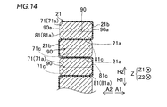
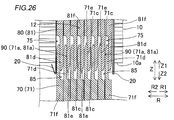
- end portions 71a of the plurality of first conductors 70 (first leg portions 71) and end portions 81a of the plurality of second conductors 80 (second leg portions 81) are formed.
- the end portion 71a includes a first surface arrangement portion 71d provided with a first surface 71c extending along the axial direction.
- the end portion 81a includes a second surface arrangement portion 81d provided with a second surface 81c extending along the axial direction.
- a plurality of the first surface arrangement portions 71d and the second surface arrangement portions 81d are arranged alternately along the radial direction.
- the joint portions 90 of the plurality of first leg portions 71 and the plurality of second leg portions 81 are arranged adjacent to each other in the radial direction in one slot 12. Note that in FIG. 13, the joint insulating member 21 is not shown for simplification.
- the plurality of joints 90 are provided so as to overlap each other when viewed in the radial direction. That is, all the joint portions 90 arranged in one slot 12 are arranged in a state of being aligned in the horizontal direction. In other words, in one slot 12, the positions of the plurality of joint portions 90 in the axial direction are substantially equal to each other.
- the joining portion 90 has a first surface 71c of the first leg portion 71 (end portion 71a) and a second surface 81c of the second leg portion 81 (end portion 81a) as viewed in the radial direction. And are joined (overlapped) parts.
- Each of the tip portion 71e of the first leg portion 71 and the tip portion 81e of the second leg portion 81 has a tapered shape. Specifically, as viewed from the circumferential direction (direction A), each of the tip end portion 71e of the first leg portion 71 and the tip end portion 81e of the second leg portion 81 has a tapered shape.
- first leg portion 71 has a first leg body portion 71f continuously provided to the first surface arrangement portion 71d provided with the first surface 71c.
- the first leg body 71f is provided on the side opposite to the tip 71e (Z2 direction side) with respect to the first surface arrangement portion 71d.
- second leg portion 81 has a second leg body portion 81f continuously provided with the second surface arrangement portion 81d provided with the second surface 81c.
- the second leg body 81f is provided on the side (Z1 direction side) opposite to the tip 81e with respect to the second surface arrangement portion 81d.
- first conductor 70 and the second conductor 80 axially opposed to each other, between the tip end portion 71e of the first leg portion 71 and the second leg portion 81 (second leg portion main body portion 81f). Is provided with a first gap portion 75.
- first conductor 70 and the second conductor 80 which are axially opposed to each other, between the tip 81e of the second leg 81 and the first leg 71 (first leg body 71f). Is provided with a second gap portion 85.
- the first leg portions 71 of each of the plurality of first conductors 70 are arranged so as to be radially adjacent to the first leg portions 71 that are in phase with each other.
- the second leg portions 81 of each of the plurality of second conductors 80 are arranged so as to be adjacent to the second leg portions 81 that are in phase with each other.
- a plurality of first leg portions 71 in phase with each other are arranged in the radial direction
- a plurality of second leg portions 81 in phase with each other are arranged. It is arranged in the radial direction.
- the eight first leg portions 71 arranged in one slot 12 are the first leg portions 71 in phase with each other.
- the eight second leg portions 81 arranged in one slot 12 are the second leg portions 81 in phase with each other.
- the first leg 71 and the second leg 81 arranged in one slot 12 are in phase with each other. That is, all of the plurality of first leg portions 72 and the plurality of second leg portions 82 arranged in each of the plurality of slots 12 are in phase with each other.
- the leg portions (71, 81) of different phases are not arranged adjacent to each other in one slot 12.
- the plurality of slots 12 provided in the circumferential direction are provided with leg portions (71, 81) of different phases every two.
- the plurality of slots 12 are provided with legs (71, 81) in the order of U phase, U phase, V phase, V phase, W phase, W phase...
- the arrangement (arrangement of phases) of the leg portions (71, 81) in the plurality of slots 12 is not limited to this.
- the core leg insulating member 20 is arranged between the wall 11 a and the teeth 13 and the first leg 71 and the second leg 81 (segment conductor 40 ).
- the core leg insulating member 20 is arranged so as to integrally cover the periphery of the plurality of second leg portions 81 arranged in parallel in the radial direction when viewed in the Z2 direction. In other words, the circumferential side and the radial sides of the plurality of second leg portions 81 arranged in parallel in the radial direction are covered with the core leg insulating member 20. Accordingly, the core leg insulating member 20 can ensure the insulation between the joint portion 90 and the stator core 10.
- the joints 90 adjacent to each other in the radial direction are insulated by the sheet-like joint insulation member 21.
- the joint insulating member 21 is provided separately from the core leg insulating member 20.
- the “coil” means a linear portion of the coil portion 30 that is arranged in the slot 12 after the first conductor 70 and the second conductor 80 are joined. Therefore, a plurality of coils are arranged in one slot 12.
- the joint insulating member 21 is formed by folding a sheet-like insulating member such as Nomex.
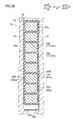
- the joining portion insulating member 21 includes the facing surface insulating portion 21a provided between the joining portions 90 adjacent in the radial direction. Further, the joint insulating member 21 is continuous from both ends in the circumferential direction of the facing surface insulating portion 21a, and at least one of the circumferential surfaces 90a of the joints 90 adjacent in the radial direction is separated by at least the insulating distance. It includes a circumferential surface insulating portion 21b which covers.
- the insulation distance is a length along the radial direction of the circumferential surface insulating portion 21b and means a distance (creeping distance) sufficient to insulate the joint portions 90 adjacent to each other in the radial direction.
- the joint insulating member 21 includes a portion 21c that covers the outer side in the radial direction of the joint 90 arranged on the outermost side in the radial direction. Further, the joint insulating member 21 includes a portion 21d that covers the inner side in the radial direction of the joint 90 arranged on the innermost side in the radial direction.
- the facing surface insulating portions 21a that are adjacent in the radial direction are connected by the circumferential surface insulating portion 21b in one or the other circumferential direction.
- the facing surface insulating portion 21a on the outer side in the radial direction and the circumferential surface insulating portion 21b provided on one side in the circumferential direction are formed to be continuous.
- the circumferential surface 90a of the joining portion 90 on the A1 direction side and the circumferential surface 90a of the joining portion 90 on the A2 direction side are alternately covered with the circumferential surface insulating portion 21b.
- the joint insulating member 21 is configured not to continuously cover the circumferential surfaces 90a of the plurality of joints 90 arranged adjacent to each other in the radial direction.
- the joint insulating member 21 has a meandering shape (bellows shape) when viewed in the axial direction. Further, since the one joint insulating member 21 insulates the joints 90 adjacent in the radial direction arranged in one slot 12 from each other, all the joints 90 in the slot 12 are insulated from each other. This makes it possible to reduce the number of steps for disposing the joint insulating member 21 as compared with the case where the plurality of joints 90 arranged in one slot 12 are individually covered with the insulating member.
- the joint insulating member 21 is configured to be expandable and contractable along the radial direction.
- the joint insulating member 21 is made of a flexible sheet-shaped insulating member and continuously covers the circumferential surfaces 90a of the plurality of joints 90 arranged adjacent to each other in the radial direction. This is because it is configured not to. Thereby, even when the first leg 71 and the second leg 81 are pressed in the radial direction or the axial direction when the first leg 71 and the second leg 81 are joined, the first leg 71 is pressed.
- the joint insulating member 21 can be deformed with the movement of 71 and the second leg 81.
- each of the core leg insulating member 20 and the joint insulating member 21 is provided separately from the insulating layer 74 and the insulating layer 84. Further, each of the core leg insulating member 20 and the joint insulating member 21 is provided apart from the insulating layer 74 and the insulating layer 84 in the axial direction.
- the length L12 of the joint insulating member 21 is smaller than the length L11 of the core leg insulating member 20 in the axial direction. Specifically, the length L11 of the core leg insulating member 20 is longer than the length L3 of the stator core 10 in the axial direction. Further, the length L12 of the joint insulating member 21 is smaller than the length L3 of the stator core 10.
- the joint insulating member 21 is provided so as to cover the joint 90 and extend from the joint 90 toward the Z1 direction side and the Z2 direction side. The length L12 of the joining portion insulating member 21 is adjusted based on the magnitude of the voltage applied to the coil portion 30 (based on the required creepage distance). Note that, in FIG. 16, the illustration of the first conductor 70 and the second conductor 80 is omitted for simplification.
- Step S1 a plurality of segment conductors 40 are prepared in step S1. Specifically, the power conductor 50 forming the power line connecting end Pt of each phase of the Y-connected coil portion 30 and the neutral point forming the neutral point connecting end Nt of each phase of the coil portion 30. The conductor 60 and the first conductor 70 and the second conductor 80 that form the other part of the coil unit 30 are prepared.
- an insulating layer 73 and a first insulating base layer 74a are formed (coated) on the conductor surface 70a of the first conductor 70 made of a conductive material such as copper.
- the insulating layer 73 and the first base insulating layer 74a are integrally formed insulating layers. That is, the insulating layer 73 and the first insulating base layer 74a are formed in the same step.
- the insulating layer 83 and the second insulating base layer 84a are formed (coated) on the conductor surface 80a of the second conductor 80 made of a conductive material such as copper. Since the insulating layer 83 and the second insulating base layer 84a are integrally formed insulating layers, the insulating layer 83 and the second insulating base layer 84a are formed in the same step.
- first conductor 70 and the second conductor 80 are molded by a molding jig (not shown), so that the first conductor 70 (FIG. 6), the second conductor 80 (FIG. 7), and the power conductor 50
- the second leg portion 81 forming a part or a part of the neutral point conductor 60 is formed.
- the forming jig (not shown) forms the first inclined portion 72c on the first conductor 70 and the second inclined portion 82c on the second conductor 80.
- the inclination angle ⁇ 1 ( ⁇ 2) of the first inclined portion 72c (second inclined portion 82c) provided on the radially outer side is equal to the first inclined portion 72c (second inclined portion 82c) provided on the radially inner side.
- the first conductor 70 and the second conductor 80 are formed so as to be larger than the inclination angle ⁇ 1 ( ⁇ 2).
- the first additional insulating layer 74c is formed (coated) on the surface 74b of the first insulating base layer 74a, and the surface 84b of the second insulating base layer 84a is formed.
- the second additional insulating layer 84c is formed (coated).
- a method of immersing the first transition part 72 (second transition part 82) in a fluid insulating material a first transition part A method of applying an insulating material to 72 (second transition part 82) by spraying, a method of mounting a heat-shrinkable tube on the first transition part 72 (second transition part 82), and a first transition part 72 (second transition) A method of winding an insulating tape around the transition portion 82) can be considered.
- step S2 an annular first coil assembly 30a (see FIG. 2) and a second coil assembly 30b (see FIG. 2) each including a plurality of segment conductors 40 are formed.
- the first coil assembly 30a and the second coil assembly 30b are formed in a state where a plurality of (for example, eight) segment conductors 40 are arranged in the radial direction and a number of the slots 12 are arranged in the circumferential direction. ..
- the power conductor 50 and the neutral point conductor 60 are arranged in the second coil assembly 30b.
- step S3 the sheet-shaped core leg insulating member 20 for insulating the slot 12 from the coil portion 30 is inserted into the slot 12.
- step S4 the second leg portions 81 of the plurality of second conductors 80, which are arranged on one axial side (Z1 direction side) of the stator core 10 among the plurality of segment conductors 40, are arranged so that the axis of the stator core 10 is not changed. It is inserted into the slot 12 of the stator core 10 from one side in the direction (Z1 direction side). As a result, the plurality of second conductors 80 are arranged on one side in the axial direction of the stator core 10 (Z1 direction side).
- Step S5 After the plurality of second conductors 80 are arranged in the slots 12, the second leg portion 81 of the second conductor 80 that is radially adjacent in one slot 12 among the plurality of second conductors 80.
- the sheet-shaped joint insulation member 21 is arranged between the two.
- step S6 the plurality of first conductors 70 are moved relative to the stator core 10 from the other axial side (Z2 direction side) of the stator core 10. As a result, the first leg portion 71 of the first conductor 70 is inserted into the slot 12. As a result, the plurality of first conductors 70 are arranged on the other axial side (Z2 direction side) of the stator core 10.
- the end portions 71 a of the first leg portions 71 and the end portions 81 a of the second leg portions 81 are arranged alternately with the first leg portions 71 of the first conductor 70.
- the second leg 81 of the second conductor 80 is arranged in the slot 12. At this time, when the first leg portion 71 of the first conductor 70 is inserted, the first leg portion 71 may be tilted radially inward, or the first leg portion 71 may be radially outwardly offset to be inserted. The interference between the first leg portion 71 and the second leg portion 81 can be easily avoided.
- step S7 the plurality of segment conductors 40 (the end portions 71a and the end portions 81a) are pressed in the radial direction, so that the first surface 71c of the first leg portion 71 and the second surface of the second leg portion 81. Bonding with the surface 81c is performed.
- stator 200 according to the second embodiment will be described with reference to FIGS. 1, 3 and 19 to 25.
- first leg 171 and the second leg 181 are not provided with an insulating layer.
- the same components as those in the first embodiment are designated by the same reference numerals as those in the first embodiment and shown in the drawing, and the description thereof is omitted.
- stator 200 The structure of the stator 200 according to the second embodiment will be described with reference to FIGS. 1, 3 and 19 to 24.
- the stator 200 is an example of the “armature” in the claims.
- the stator 200 together with the rotor 101, constitutes a part of the rotary electric machine 202.
- the stator 200 includes a sheet-shaped insulating member 120 and a coil portion 130 (see FIG. 1).
- the coil unit 130 also includes a first coil assembly 130a (anti-lead side coil) (see FIG. 21) and a second coil assembly 130b (lead side coil) (see FIG. 21).
- the coil portion 130 includes a plurality of segment conductors 140 (see FIG. 20).
- each of the multiple-phase first conductors 170 includes a pair of first leg portions 171 and a first crossover portion 172.
- the first transition part 172 has a first bent part 172a and a pair of first skewed parts 172b.
- each of the multiple-phase second conductors 180 includes a pair of second leg portions 181 (see FIG. 21) and a second crossover. Section 182 (see FIG. 21).
- the second transition part 182 has a second bent part 182a (see FIG. 21) and a pair of second skewed parts 182b (see FIG. 21).
- the first leg 171 and the second leg 181 have substantially equal lengths (see FIG. 21).
- the insulation performance of the first transition part 172 and the second transition part 182 is higher than the insulation performance of the first leg part 171 and the second leg part 181.
- the insulating layer is not provided on the pair of first leg portions 171 (second leg portions 181) of the segment conductor 140. That is, the first leg 171 (second leg 181) is not covered with the insulating layer and the conductor surface 140b is exposed.
- first transition parts 172 at least a portion where the first transition parts 172 of different phases are arranged to be adjacent to each other, and at least the second transition parts 182 of at least different phases.
- An insulating layer is provided in each of the portions where the two transition portions 182 are arranged adjacent to each other.
- each of the first bent portion 172a and the pair of first skewed portions 172b of the first transition portion 172 is covered with an insulating layer 174.
- each of the second bent portion 182a and the pair of second skewed portions 182b of the second transitional portion 182 is covered with an insulating layer 184 (see FIG. 21).
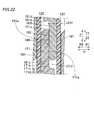
- the stator 200 has a leaf spring member 210 provided in each of the plurality of slots 12 so as to be sandwiched between the coil portion 130 and the opening 12 a (projection 13 b) of the slot 12. Equipped with. That is, the leaf spring member 210 is provided in the tip gap 12b provided inside the slot 12 in the radial direction.
- the leaf spring member 210 is configured by a leaf spring member that can bend and deform in the R direction.
- the leaf spring member 210 is configured to maintain the contact state of the contact portion 190 described below by pressing the coil portion 130 from the R1 side.
- the leaf spring member 210 has a leaf spring shape that curves along the Z direction. Specifically, in the leaf spring member 210, a metal plate such as SUS (stainless steel) extending along the Z direction is curved along the Z direction.
- the leaf spring member 210 has a Z-direction length L4 smaller than the Z-direction length L3 (see FIG. 19) of the stator core 10.
- the leaf spring member 210 is made of a material (for example, Inconel (registered trademark)) that has a biasing force (elastic force), is a non-magnetic material, and has heat resistance. preferable.
- the leaf spring member 210 has a diameter of the coil portion 130 such that the first surface 171a of the first leg portion 171 of the first conductor 170 and the second surface 181a of the second leg portion 181 of the second conductor 180 are in contact with each other. It is configured to press from the inside in the direction.
- a contact portion 190 is formed by the contact between the first surface 171a of the first leg portion 171 and the second surface 181a of the second leg portion 181.
- the contact portion 190 is an example of the “joint portion” in the claims.
- the first surface 171a and the second surface 181a are in contact with each other by being pressed by the leaf spring member 210 without a bonding material between the first surface 171a and the second surface 181a. That is, the first surface 171a and the second surface 181a are not joined, and the contact state between the first surface 171a and the second surface 181a is maintained by the pressing force of the leaf spring member 210.
- each of the plurality of contact portions 190 is arranged in the central portion P1 of the stator core 10 in the axial direction in the slot 12.
- the leaf spring member 210 is also arranged at the central portion P1 in the axial direction of the stator core 10. Specifically, the leaf spring member 210 is provided so as to overlap each of the plurality of contact portions 190 when viewed in the radial direction.
- each of the first surface 171a and the second surface 181a is plated. That is, the plated surfaces (the first surface 171a and the second surface 181a) are in contact with each other.
- metals such as Ni, Ag, Au, and Sn are used.
- the plating process may be performed using a plurality of metals (for example, Ni and Ag) among the above metals.
- the first leg portion 171 includes a first surface arranging portion 171b, a tip portion 171c, a first leg portion main body portion 171d, and a first step portion 171e.
- a gap 171f is provided between the first step 171e and the tip 181c of the second leg 181.
- the second leg portion 181 includes a second surface arrangement portion 181b, a tip portion 181c, a second leg portion main body portion 181d, and a second step portion 181e.
- a gap 181f is provided between the second step 181e and the tip 171c of the first leg 171.
- first surface arranging portion 171b and the second surface arranging portion 181b are provided at the central portion P1 (see FIG. 21) of the stator core 10 in the axial direction.
- the stator 200 includes an insulating member 120.
- the insulating member 120 includes an insulating layer made of polyphenylene sulfide resin (PPS: Poly Phenylene Sulfide Resin), aramid paper, or the like.
- PPS polyphenylene sulfide resin
- the insulating member 120 is formed in a sheet shape.
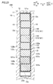
- the insulating member 120 electrically connects the first insulating portion 121 for electrically insulating the stator core 10 and the coil portion 130, and electrically connects the segment conductors 140 in which the leg portions (171, 181) are inserted in the same slot 12.
- a second insulating portion 122 for electrically insulating.
- the first insulating portion 121 is provided in the slot 12 at least between the inner side surface 12c of the slot 12 and the leg portions (171, 181). Specifically, the first insulating portion 121 includes a portion 121a that linearly extends around the region 12d in which all the segment conductors 140 in the slot 12 are arranged. The linearly extending portion 121a is arranged so as to surround most of the periphery of the region 12d.
- the second insulating portion 122 is provided in the slot 12 at least between the plurality of leg portions (171, 181) inserted in the same slot 12.
- the second insulating portion 122 has a meandering portion 122a that extends from the segment conductor 140 arranged on the R1 side to the segment conductor 140 arranged on the R2 side in the same slot 12.
- the portion 122a having a meandering shape extends between the segment conductors 140 adjacent to each other in the R direction in the A direction of the stator core 10 and extends between the segment conductors 140 and the inner surface 12c of the slot 12 in the R direction. It meanders to extend in the direction.
- the meandering portion 122a includes a portion 122b extending between the segment conductors 140 in the A direction of the stator core 10 and a portion 122c extending in the R direction between the segment conductor 140 and the inner side surface 12c of the slot 12. .. From the R1 side to the R2 side, a portion 122b and a portion 122c arranged on one side in the A direction, and a portion 122b and a portion 122c arranged on the other side in the A direction are continuously formed in this order.
- the second insulating portion 122 is integrally formed with the first insulating portion 121 by connecting the portion 122a having the meandering shape to the linearly extending portion 121a of the first insulating portion 121.
- the first insulating portion 121 includes an insulating layer 121b.
- the first insulating portion 121 also includes a fixed layer 121d having a foaming agent 121c that foams due to heat.
- the fixing layer 121d expands due to foaming of the foaming agent 121c, thereby fixing each of the first leg portion 171 and the second leg portion 181 to the stator core 10 at least in the axial direction.
- the fixed layer 121d of the first insulating portion 121 is configured to bond and fix each of the first leg 171 and the second leg 181 to the stator core 10.
- the fixed layer 121d is provided on both surfaces of the insulating layer 121b.
- the thermosetting resin 121e cures. Accordingly, it is not necessary to use varnish or the like to fix each of the first leg 171 and the second leg 181.
- the first insulating portion 121 is illustrated as having a larger thickness than it actually is. Further, in FIG. 24, the illustration of the stator core 10 and the like is omitted for simplification.
- the second insulating portion 122 also has the same configuration (composition) as the first insulating portion 121.
- step S11 a preparation process for the segment conductor 140 is performed.
- the first leg portion 171 (second leg portion 181) is not provided with an insulating layer and is insulated from the first transition portion 172 (second transition portion 182) of the first conductor 170 (second conductor 180).
- Form layers (174, 184).
- step S12 the insulating member 120 is placed (inserted) in the slot 12.
- step S13 the second leg 181 (see FIG. 21) of the second conductor 180 is inserted into the slot 12 from the other axial side (Z1 direction side).
- step S14 the first leg 171 (see FIG. 21) of the first conductor 170 is inserted into the slot 12 from one side in the axial direction (Z2 direction side). At this time, the first leg 171 is arranged such that the first surface 171a of the first leg 171 and the second surface 181a of the second leg 181 face each other.
- step S15 the leaf spring member 210 (see FIG. 21) is inserted into the tip gap 12b in the slot 12 from one axial side (for example, the Z1 direction side).
- step S16 the stator core 10 is heated and the fixed layer 121d is heated, so that the foaming agent 121c is foamed and the fixed layer 121d is expanded.
- the coil portion 130 is fixed to the slot 12 at least in the axial direction.
- the first transition part (72, 172) and the second transition part (82, 182) are arranged in the first leg part (71). , 171) and the second leg (81, 181) have a higher voltage value that can be insulated. As a result, each of the first transition parts (72, 172) and the second transition parts (82, 182) can be more reliably insulated.
- first segment conductor (70, 170) and the second segment conductor (80, 180) are separated from each other. (Separated).
- first segment conductor (70, 170) is moved to one side in the axial direction (the side where the first leg portion (71, 171) is provided with respect to the first crossover portion (72, 172)).
- second segment conductor (80, 180) is moved to the other side in the axial direction (the side where the second leg (81, 181) is provided with respect to the second crossover (82, 182)).
- first leg portion (71, 171) and the second leg portion (81, 181) are arranged close to each other and are joined to each other. Thereby, the first leg portion (71, 171) and the second leg portion (71, 171) are not inserted into the slot (12) along the axial direction, respectively, without inserting the first leg portion (72, 172) and the second leg portion (82, 182).
- the second legs (81, 181) can be brought close to each other and can be joined to each other.
- the segment conductors (40, 140) can be arranged in the slots (12). That is, after arranging the segment conductors (40, 140) in the slots (12), the first transition parts (72, 172) (second transition parts (82, 182)) are joined by a joining process such as welding. You don't have to. This can prevent the crossover portions (72, 82, 172, 182) from being damaged (the insulating layers (74, 84, 174, 184) being damaged) due to the bonding process.
- the crossovers (72, 82, 172, 182) can be more reliably insulated from each other. At the same time, it is possible to prevent the crossover portions (72, 82, 172, 182) that have been subjected to the insulation treatment from being damaged (the insulation layers (74, 84, 174, 184) being damaged).
- each of the pair of first leg portions (71) is provided with the first leg portion side insulating layer (73), and the pair of second leg portions ( A second leg side insulating layer (83) is provided on each of 81).
- at least a portion of the first crossover portion (72) where the first crossover portions (72) of different phases are arranged adjacent to each other is formed from the first leg side insulating layer (73).
- a first crossover side insulating layer (74) having a large thickness is provided.
- at least a portion of the second transition part (82) in which the second transition parts (82) of different phases are arranged adjacent to each other is formed from the second leg side insulating layer (83).
- a second crossover side insulating layer (84) having a large thickness is provided.
- the thickness (t3+t4) of the first crossover side insulating layer (74). ) Is larger than the thickness (t1) of the first leg-side insulating layer (73), and the thickness (t5+t6) of the second crossover-side insulating layer (84) is equal to that of the second leg-side insulating layer (83).
- the armature core It is possible to prevent 10) from increasing in size.
- first leg portion (71) and the second leg portion (81) are brought close to each other without inserting the first transition portion (72) and the second transition portion (82) into the slot (12). Therefore, it is not necessary to insert the coil portion (30) from the inside in the radial direction.
- the insulating layers (74, 84) of the transition portions (72, 82) from being damaged by the pressure from the inside in the radial direction during insertion from the inside in the radial direction.
- the gap between the radially adjacent crossover portions (72, 82) for forming the additional insulating layers (74c, 84c) is crushed by the pressure from the radial inside when inserting from the radial inside. It is possible to prevent it.
- each of the first segment conductor (70) and the second segment conductor (80) in the axial direction, a plurality of armature cores (10) divided in the circumferential direction are used and the divided armatures are used.
- By moving the core (10) radially it is also not necessary to place the legs (71, 81) in the slots (12).
- the loss of the armature core (10) such as iron loss due to an increase in magnetic resistance
- first leg portion (71) and the second leg portion (81) are brought close to each other without inserting the first transition portion (72) and the second transition portion (82) into the slot (12). Therefore, it is not necessary to increase the area of the slot (12) in plan view. As a result, it is possible to prevent the physique of the armature core (10) from increasing, and it is possible to prevent the loss of the armature (10) from deteriorating.
- the first crossing portion side insulating layer (74) is integrally formed with the first leg portion side insulating layer (73) and the first leg portion side insulating layer (74) is formed.
- a first insulating base layer (74a) having a thickness (t3) equal to the thickness (t1) of the layer (73), and a first additional insulation provided on the surface (74b) of the first insulating base layer (74a).
- the second crossing portion side insulating layer (84) is formed integrally with the second leg portion side insulating layer (83) and is equal to the thickness (t2) of the second leg portion side insulating layer (83).
- the thickness (t3+t4) of the first crossover side insulating layer (74) is equal to the thickness (t4) of the first additional insulating layer (74c) of the first leg side insulating layer (73). It can be easily made larger than the thickness (t1).
- the thickness (t5+t6) of the second crossover side insulating layer (84) is calculated from the thickness (t2) of the second additional insulating layer (84c) by the thickness (t2) of the second leg side insulating layer (83). Can also be easily enlarged.
- the adjacent first crossover portions (72) and the adjacent first transition portions (72) are adjacent to each other.
- the two transition parts (82) can be insulated more reliably and easily.
- the plurality of first leg portions (71) are radially arranged in the one slot (12) and the plurality of second leg portions (81) are arranged. ) Are arranged in the radial direction.
- a plurality of first crossover portions (72) are arranged in the radial direction on the other side of the slot (12) in the axial direction.
- a plurality of second crossover portions (82) are arranged in the radial direction on one axial side of the slot (12 ).
- at least a part of the plurality of first transition parts (72) arranged in the radial direction is provided with the first transition part side insulating layer (74) of the first transition parts (72).
- a first inclined portion (72c) inclined to one side in the radial direction is provided between the portion and the first leg portion (71). Further, at least a part of the plurality of second transition portions (82) arranged in the radial direction is provided with the second transition portion-side insulating layer (84) of the second transition portion (82). A second inclined portion (82c) inclined to one side in the radial direction is provided between the portion and the second leg portion (81). According to this structure, by providing the first inclined portion (72c), the first crossover portion (72) can be displaced to one side in the radial direction with respect to the first leg portion (71). ..
- the second transitional portion (82) can be arranged so as to be displaced to one side in the radial direction with respect to the second leg portion (81).
- the size of the gap between the first crossover portions (71) adjacent to each other in the radial direction can be easily adjusted by the inclination angle ( ⁇ 1) of the first inclined portion (72c).
- the size of the gap between the second crossover portions (82) adjacent to each other in the radial direction can be easily adjusted by the inclination angle ( ⁇ 2) of the second inclined portion (82c).
- each of the plurality of first inclined portions (72c) and the plurality of second inclined portions (82c) is arranged in the radial direction.
- the first inclined portion (72c) on the one side in the radial direction has a larger inclination angle ( ⁇ 1) with respect to the axial direction than the first inclined portion (72c) on the other side in the radial direction.
- the second inclined portion (82c) on the one side in the radial direction has a larger inclination angle ( ⁇ 2) with respect to the axial direction than the second inclined portion (82c) on the other side in the radial direction.
- a gap can be surely provided between the adjacent first crossover portions (71), and a gap can be surely provided between the adjacent second crossover portions (82). it can.
- This makes it possible to easily provide the first crossover-side insulating layer (74) in the gap between the adjacent first crossovers (71), and also to provide the space between the adjacent second crossovers (82).
- the second crossover-side insulating layer (84) can be easily provided in the gap.
- the plurality of first leg portions (71) in phase with each other are arranged in the radial direction in one slot (12), and the plurality of first leg portions (71) in phase with each other are arranged.
- the two legs (81) are arranged in the radial direction. According to this structure, it is possible to prevent the voltage difference between the first legs (71) from becoming excessively large in the slot (12), and the voltage difference between the second legs (81). Can be prevented from becoming excessively large.
- the thickness (t1) of the first leg side insulating layer (73) is smaller than the thickness (t3+t4) of the first crossing portion side insulating layer (74), and each of the second leg side insulating layer (83).
- T2 is smaller than the thickness (t5+t6) of the second crossover-side insulating layer (84), the adjacent first leg portions (71) can be reliably insulated from each other and the adjacent first leg portions (71) can be reliably insulated from each other.
- the two legs (81) can be reliably insulated from each other.
- the armature (100) is provided separately from the first leg side insulating layer (73) and the second leg side insulating layer (83), and the slot ( 12) and a sheet-shaped core leg insulating member (20) arranged between the coil portion (30). Further, the armature (100) is provided separately from the core leg insulating member (20), and is a sheet-like joint that insulates the joint portions (90) that are adjacent in the radial direction in one slot (12). A partial insulating member (21) is provided. Further, each of the core leg insulating member (20) and the joint insulating member (21) is provided separately from the first crossover side insulating layer (74) and the second crossover side insulating layer (84). There is.
- the core leg insulating member (20) prevents the slot (12) and the coil. It is possible to ensure insulation between the part (30). Even when the first crossover side insulating layer (74) and the second crossover side insulating layer (84) are damaged, the insulation between the joints (90) is maintained by the joint insulation member (21). Can be secured.
- the first transitional portion (72) includes the first bendable portion (72a) that is bent at the center of the first transitional portion (72) and the first bendable portion (72a).
- 72a) has a pair of first skewed portions (72b) linearly extending toward the pair of first legs (71).
- the second transitional portion (82) includes a second bendable portion (82a) that is bent at the center of the second transitional portion (82), and a pair of second leg portions (81) from the second bendable portion (82a).
- the first crossover-side insulating layer (74) is provided on each of the first bent portion (72a) and the pair of first oblique portions (72b).
- the second crossover-side insulating layer (84) is provided on each of the second bent portion (82a) and the pair of second skewed portions (82b). According to this structure, as compared with the case where the first crossover-side insulating layer (74) is provided only on one of the first bent portion (72a) and the pair of first oblique portions (72b), The adjacent first crossover portions (72) can be more reliably insulated from each other.
- the second crossover-side insulating layer (84) is provided only on one of the second bent portion (82a) and the pair of second skewed portions (82b), the second crossover adjacent to each other is provided.
- the parts (82) can be more reliably insulated from each other.
- the first additional insulating layer (74c) of the first crossover side insulating layer (74) provided in each of the skewed portions (72b) is integrally provided.
- the second additional insulating layer (84c) of the second crossover side insulating layer (84) provided in the second bent portion (82a) and the pair of second skewed portions (82b) are provided, respectively.
- the second additional insulating layer (84c) of the second crossover side insulating layer (84) is integrally provided.
- the first additional insulating layer (74c) of the first bent portion (72a) and the first additional insulating layer (74c) of each of the pair of first oblique portions (72b) are separated.
- the number of components can be reduced and the number of steps for forming the first additional insulating layer (74c) can be reduced as compared with the case where the first additional insulating layer (74c) is provided.
- the second additional insulating layer (84c) of the second bent portion (82a) and the second additional insulating layer (84c) of each of the pair of second oblique portions (82b) are provided separately. Compared with the case, it is possible to reduce the number of parts and the number of steps for forming the second additional insulating layer (84c).
- the first crossover side insulating layer (74) has the first crossover (72) in the cross section orthogonal to the direction in which the first crossover (72) extends. It is provided so as to surround the circumference.
- the second crossover side insulating layer (84) is provided so as to circumferentially surround the second crossover (82) in a cross section orthogonal to the direction in which the second crossover (82) extends. ..
- a part of the first crossover part (72) is covered with the first crossover part side insulating layer (74) in the cross section orthogonal to the direction in which the first crossover part (72) extends.
- the adjacent first crossover portions (72) can be more reliably insulated from each other.
- the first crossover side insulating layer (74) is formed so as to cover a part of the first crossover (72) in a cross section orthogonal to the direction in which the first crossover (72) extends. Therefore, since it is not necessary to control (adjust) the first crossover side insulating layer (74) so as not to be partially formed, the formation of the first crossover side insulating layer (74) can be facilitated.
- the adjacent second transition parts (82) can be more reliably insulated from each other.
- the second crossover side insulating layer (84) is formed so as to cover a part of the second crossover (82) in a cross section orthogonal to the direction in which the second crossover (82) extends.
- the insulating layer is not provided on each of the pair of first leg portions (171) and the pair of second leg portions (181). Further, at least a portion of the first transition portion (172) in which the first transition portions (172) of different phases are arranged adjacent to each other, and a portion of the second transition portion (182), At least, the insulating layers (174, 184) are provided in the portions where the second transition parts (182) of different phases are arranged adjacent to each other. According to this structure, the leg portions (171, 181) are not provided with the insulating layer while ensuring the insulation between the transition portions (172, 182), so that the coil portion (130) in the slot (12) is provided. The space factor of can be increased.
- the first transition part (72, 172) is bent at the center of the first transition part (72, 172). 172a) and a pair of first oblique portions (72b, 172b) extending from the first bent portion (72a, 172a) toward the pair of first leg portions (71, 171).
- the second bridging portion (82, 182) includes a second bent portion (82a, 182a) that is bent at the center of the second bridging portion (82, 182), and a pair of the second bent portion (82a, 182a). It has a pair of second oblique portions (82b, 182b) extending toward the second leg (81, 181) side.
- the pair of first oblique portions (72b, 172b) extend so as to intersect with each other and are arranged so that their positions in the radial direction are displaced from each other.
- the pair of second skewed portions (82b, 182b) extend so as to intersect with each other and are arranged so that their positions in the radial direction are displaced from each other.
- at least one of the pair of first oblique portions (72b, 172b) is partially provided on the surface (72d) facing the radial direction, and the first crossover portions (72, 172) of different phases are provided. It has an adjacent part (72e).
- At least one of the pair of second skew portions (82b, 182b) is partially provided on the surface (82d) facing the radial direction and is adjacent to the second crossover portions (82, 182) of different phases. Having a portion (82e).
- the entire surface (72d) of the first skew portion (72b, 172b) (the entire surface (82d) of the second skew portion (82b, 182b)) is adjacent to a different phase.
- the crossover portions (72, 82, 172, 182) that are adjacent in the radial direction can be more reliably insulated.
- the pair of first leg portions (71, 171) has a diameter equal to the radial width (W11) of the first leg portions (71, 171). The positions in the direction are displaced from each other. Further, the pair of second leg portions (81, 181) are arranged such that their radial positions are displaced from each other by the radial width (W12) of the second leg portions (81, 181). The pair of first oblique portions (72b, 172b) are arranged such that their radial positions are displaced from each other by the radial width (W11) of the first leg portions (71, 171).
- the pair of second skewed portions (82b, 182b) are displaced from each other in the radial direction by the width (W12) of the second leg (81, 181) in the radial direction.
- the pair of first leg portions (71, 171) can be arranged in the lanes (conductor arrangement regions provided in a ring shape) adjacent to each other in the radial direction, and at the same time, the pair of first oblique portions can be arranged.
- the row portions (72b, 172b) can be arranged in lanes adjacent to each other in the radial direction.
- pair of second leg portions (81, 181) can be arranged in lanes that are adjacent to each other in the radial direction, and the pair of second skew portions (82b, 182b) can be adjacent to each other in the radial direction. Can be placed in the lane.
- the plurality of first leg portions (71, 171) and the plurality of second leg portions (81, 181) arranged in each of the plurality of slots (12). ) are all in phase with each other. According to this structure, since the leg portions (71, 81, 171, 181) of different phases are not adjacent to each other in one slot (12), the leg portions (71, 81, 171, 181). It is possible to make the insulation performance of) relatively small. As a result, since it is not necessary to perform an insulating treatment such as providing an insulating coating having a relatively large thickness on the leg portions (71, 81, 171, 181), the coil portion (30, 130) is occupied in the slot (12). The product ratio can be further improved.
- the present invention is not limited to this.
- the thickness t3 of the first base insulating layer 74a may be made larger than the thickness t1 of the insulating layer 73 (first leg side insulating layer).
- the thickness t5 of the second base insulating layer 84a may be made larger than the thickness t2 of the insulating layer 83 (second leg side insulating layer) in the state where the second additional insulating layer 84c is not provided.
- the example in which the first additional insulating layer 74c is provided in the first bent portion 72a and the second additional insulating layer 84c is provided in the second bent portion 82a has been shown.
- the present invention is not limited to this.
- the first additional insulating layer 74c may not be provided in the first bent portion 72a
- the second additional insulating layer 84c may not be provided in the second bent portion 82a.
- the first additional insulating layer 74c is provided on the entire first skewed portion 72b, and the second additional insulating layer 84c is provided on the entire second skewed portion 82b.
- the present invention is not limited to this.
- the first additional insulating layer 74c may not be provided in the above portion. ..
- the second additional insulating layer 84c may not be provided in the above portion. ..
- the first inclined portion 72c is provided in addition to the radially innermost first transition portion 72 among the plurality of first transition portions 72 arranged in the radial direction.
- the first inclined portions 72c may be provided on all of the plurality of first crossover portions 72 arranged in the radial direction.
- the second inclined portions 82c may be provided on all of the plurality of second crossover portions 82 arranged in the radial direction.
- each of the first inclined portion 72c and the second inclined portion 82c is inclined outward in the radial direction
- the present invention is not limited to this.
- each of the first inclined portion 72c and the second inclined portion 82c may be inclined inward in the radial direction.
- the 1st inclination part 72c and the 2nd inclination part 82c may incline in the mutually opposite direction in a radial direction.
- each of the first additional insulating layer 74c of the insulating layer 74 (first crossing portion side insulating layer) provided in the first bent portion 72a and the pair of first skewed portions 72b.
- the first additional insulating layer 74c of the insulating layer 74 (first crossing portion side insulating layer) provided in the above is integrally provided, the present invention is not limited to this.
- first additional insulating layer 74c may be provided separately from each other.
- the first additional insulating layer 74c and the first insulating base layer 74a are made of the same material, and the second additional insulating layer 84c and the second insulating base layer 84a are made of the same material.
- the present invention is not limited to this.
- the first additional insulating layer 74c and the first insulating base layer 74a are made of different materials, and the second additional insulating layer 84c and the second insulating base layer 84a are made of different materials. Good.
- the present invention is not limited to this. ..
- the first additional insulating layer 74c and the second additional insulating layer 84c may be formed after forming the assembly (30a, 30b).
- the first additional insulating layer 74c and the second additional insulating layer 84c may be formed in a state where the assemblies (30a, 30b) are partially formed (a state where only some of the segment conductors (40) are combined). Good.
- the joint portion 90 is arranged in the slot 12
- the present invention is not limited to this.
- a part of the joint portion 90 may be arranged in the slot 12 (see FIG. 26).
- the entire joint portion 90 may be arranged outside the slot 12 (see FIG. 27).
- the joint portion 90 is provided on the other side (Z2 direction side) in the axial direction within the slot 12 of the stator core 10 (armature core) has been shown, but the present invention is not limited to this. I can't.
- the joint portion 90 may be provided at the center or one side (Z1 direction side) in the axial direction of the stator core 10 (armature core).
- first and second embodiments an example in which a plurality of sets of the first leg portion 71 (171) and the second leg portion 81 (181) is provided in the slot 12 has been shown.
- the present invention is not limited to this. Only one set of the first leg 71 (171) and the second leg 81 (181) may be provided in the slot 12.
- the pair of first legs 71 of the first conductor 70 have the same length (L1), and the pair of second legs 81 of the second conductor 80 have the same length.
- L1 the length of first leg portions 271 of the first conductor 270
- the pair of second leg portions 281 of the second segment conductor 280 have different lengths (see FIG. 28A). 28B)). That is, in this case, each of the first segment conductor 270 and the second segment conductor 280 has a J-shape (substantially J-shape).
- the length of the second leg portion 81 is longer than the length of the first leg portion 71, but the present invention is not limited to this.
- the length of the second leg portion 81 may be shorter than the length of the first leg portion 71.
- stator 100 (200) (armature) constitutes a part of the inner rotor type rotating electric machine 102 (202)
- the stator may form part of an outer rotor type rotating electrical machine.
- the second conductor 80 (180) is the lead-side conductor, and the first conductor 70 (170) is the non-lead-side conductor. Is not limited to this.
- the second conductor 80 (180) may be a conductor on the non-lead side and the first conductor 70 (170) may be a conductor on the lead side.
- the present invention is not limited to this.
- the present invention can also be applied to a stator including the core leg insulating member 20 and the joint insulating member 21 that are not in a sheet shape.
- the present invention is not limited to this.
- an insulating member having a ladder shape may be arranged in the slot 12.
- the insulating member 220 includes a first insulating portion 221 and a second insulating portion 222.
- the first insulating portion 221 is composed of an annular portion 221a provided in an annular shape so as to surround the area 12d in which all the segment conductors 140 in the slot 12 are arranged.
- the second insulating portion 222 is composed of an inter-segment conductor portion 222a provided between the segment conductors 140 in the same slot 12 so as to extend in the circumferential direction (A direction) of the stator core 10.
- the inter-segment conductor portion 222a is continuously formed with the annular portion 221a.
- the insulating member 220 has a ladder shape when viewed from the Z direction.
- the present invention is not limited to this. If the crossover portions (172, 182) have a higher insulation performance (voltage value that can be insulated) than the leg portions (171, 181), the crossover portions (172, 182) are not provided with the insulating layers (174, 184). May be.
- Stator core (armature core) 12 slots 20 core leg insulating member 21 joint insulating member 30, 130 coil part 70, 170, 270 first conductor 71, 171, 271 first leg 71a end (on one side in the axial direction of the first leg) edge) 71b End (end on the other axial side of the first leg) 72,172 1st crossing part 72a, 172a 1st bending part 72b, 172b 1st slanting part 72c 1st inclined part 72d surface (surface of 1st slanting part) 72e portion (first skewed portion) 73 Insulation layer (first leg side insulation layer) 74 Insulation layer (first crossover side insulation layer) 74a First insulating base layer 74b Surface (surface of first insulating base layer) 74c First additional insulating layer 80, 180, 280 Second conductor 81, 181, 281 Second leg 81a End (end of second leg in the other axial direction) 81b End (end on one side in the axial direction
Abstract
In an armature (100), first jumper wires (72) and second jumper wires (82), which are each disposed such that jumper wires having different phases are adjacent to each other, have higher voltage values at which insulation is possible than first legs (71) and second legs (81) which are each disposed such that legs having the same phase are adjacent to each other.
Description
本発明は、電機子に関する。
The present invention relates to an armature.
従来、渡り部が設けられたセグメント導体を備える電機子が知られている。このような電機子は、たとえば、特開2004-64989号公報に開示されている。
Conventionally, an armature provided with a segment conductor provided with a transition portion is known. Such an armature is disclosed in, for example, Japanese Patent Laid-Open No. 2004-64989.
上記特開2004-64989号公報には、複数のスロットが設けられているステータコアを備えるステータが開示されている。ステータコアのスロットには、U字形状を有するセグメント導体が挿入されている。具体的には、セグメント導体は、直線状に延びる一対のスロット挿入部と、一対のスロット挿入部の一端同士を連結する挿入側エンド部とを含む。一対のスロット挿入部の各々は、互いに異なるスロットに挿入されている。また、挿入側エンド部は、スロットの軸方向一方側から突出するように設けられている。また、セグメント導体は、スロット挿入部の他端においてスロット挿入部と一体的に設けられている一対の接合側エンド部を有する。一対の接合側エンド部の各々は、スロットの軸方向他方側から突出するように設けられている。一対の接合側エンド部は、スロットの軸方向他方側から突出した状態で互いに近づくように屈曲させられた後、互いの端部同士が接合される。
The above-mentioned Japanese Patent Laid-Open No. 2004-64989 discloses a stator including a stator core provided with a plurality of slots. A segment conductor having a U shape is inserted into the slot of the stator core. Specifically, the segment conductor includes a pair of linearly extending slot insertion portions and an insertion-side end portion connecting one ends of the pair of slot insertion portions. Each of the pair of slot insertion portions is inserted into different slots. Further, the insertion-side end portion is provided so as to project from one axial side of the slot. Further, the segment conductor has a pair of joining side end portions integrally provided with the slot insertion portion at the other end of the slot insertion portion. Each of the pair of joining-side end portions is provided so as to project from the other axial side of the slot. The pair of joining-side end portions are bent so as to come close to each other in a state of protruding from the other axial side of the slot, and then the respective end portions are joined.
ここで、複数の接合側エンド部(挿入側エンド部)の各々が互いに異なる相の接合側エンド部(挿入側エンド部)同士と隣り合うように配置されるとともに、複数のスロット挿入部の各々がスロット内において互いに同相のスロット挿入部と隣り合うように配置される場合がある。この場合、同相同士が隣り合うように配置されるスロット挿入部よりも、異なる相同士が隣り合うように配置されている接合側エンド部(挿入側エンド部)の方が、高い絶縁性能が要求される。そこで、上記特開2004-64989号公報のように、挿入側エンド部および接合側エンド部の各々に粉体塗装膜を形成するなどの絶縁処理を施すことにより、挿入側エンド部(接合側エンド部)の絶縁性能をスロット挿入部よりも高めることが考えられる。
Here, each of the plurality of joining-side end portions (insertion-side end portions) is arranged adjacent to the joining-side end portions (insertion-side end portions) of different phases, and each of the plurality of slot insertion portions is arranged. May be arranged so as to be adjacent to the slot insertion portions having the same phase in each slot. In this case, the joint side end portion (insertion side end portion) in which different phases are arranged adjacent to each other has higher insulation performance than the slot insertion portion in which the same phase is arranged adjacent to each other. Required. Therefore, as described in Japanese Patent Laid-Open No. 2004-64989, the insertion-side end portion (bonding-side end portion) is subjected to an insulating treatment such as forming a powder coating film on each of the insertion-side end portion and the joining-side end portion. It is conceivable that the insulation performance of the part) is higher than the slot insertion part.
しかしながら、上記特開2004-64989号公報に記載されているような従来の電機子では、絶縁処理が施された渡り部の少なくとも一方がスロットを通過するため、渡り部(渡り部に形成された絶縁層等)が破損する場合がある。また、セグメント導体をスロットに挿入した後、渡り部同士を溶接等の接合処理によって接合する際に、接合処理に起因して渡り部(渡り部に形成された絶縁層等)が破損する場合がある。すなわち、上記特開2004-64989号公報に記載されているような従来の電機子では、セグメント導体を軸方向に沿ってステータコアに配置する場合に、絶縁処理が施された渡り部が破損(渡り部に形成された絶縁層等が破損)するという問題点がある。なお、分割コア(周方向に分割されたステータコア)によりセグメント導体をステータコアに径方向挿入することは可能である一方、ステータコアが分割されることに起因して損失(磁気抵抗が大きくなることに起因する鉄損等)が悪化する場合がある。
However, in the conventional armature described in JP-A-2004-64989, at least one of the insulated transition portions passes through the slot, so that the transition portion (formed on the transition portion is formed. Insulation layer, etc.) may be damaged. Also, after the segment conductors are inserted into the slots, when joining the crossover parts by a joining process such as welding, the crossover part (such as the insulating layer formed on the crossover part) may be damaged due to the joining process. is there. That is, in the conventional armature as described in JP 2004-64989 A, when the segment conductor is arranged on the stator core along the axial direction, the insulation-treated crossover portion is damaged (crossover). There is a problem that the insulating layer and the like formed on the portion are damaged). It is possible to insert the segment conductors into the stator core in the radial direction by the split cores (the stator cores divided in the circumferential direction), but the loss due to the splitting of the stator core (increased magnetic resistance Iron loss, etc.) may worsen.
この発明は、上記のような課題を解決するためになされたものであり、この発明の1つの目的は、セグメント導体を軸方向に沿って電機子コアに配置する場合に、渡り部同士をより確実に絶縁しながら、絶縁処理が施された渡り部が破損するのを防止することが可能な電機子を提供することである。
The present invention has been made in order to solve the above problems, and one object of the present invention is to make the connecting portions more sensible when arranging the segment conductors in the armature core along the axial direction. An object of the present invention is to provide an armature capable of preventing damage to a crossover portion subjected to an insulation treatment while surely insulating.
上記目的を達成するために、この発明の第1の局面における電機子は、軸方向に延びる複数のスロットが設けられている電機子コアと、軸方向に沿って軸方向の一方側に延びる一対の第1脚部と、一対の第1脚部の軸方向の他方側の端部同士を接続する第1渡り部とを含む複数相の第1セグメント導体と、軸方向に沿って軸方向の他方側に延びる一対の第2脚部と、一対の第2脚部の軸方向の一方側の端部同士を接続する第2渡り部とを含む複数相の第2セグメント導体と、第1脚部の軸方向の一方側の端部、および、第2脚部の軸方向の他方側の端部が、1つのスロット内または1つのスロットの軸方向の外側において接合されている接合部と、を含むコイル部と、を備え、複数の第1セグメント導体の各々の第1脚部は、互いに同相の第1脚部同士と隣り合うように配置され、複数の第2セグメント導体の各々の第2脚部は、互いに同相の第2脚部同士と隣り合うように配置され、複数の第1セグメント導体の各々の第1渡り部は、互いに異なる相の第1渡り部同士と隣り合うように配置され、複数の第2セグメント導体の各々の第2渡り部は、互いに異なる相の第2渡り部同士と隣り合うように配置され、第1渡り部および第2渡り部は、第1脚部および第2脚部よりも絶縁可能な電圧値が高い。なお、接合部とは、接合剤を介して接合されている部分のみならず、接合剤を介さずに接触しているだけの部分を含む広い意味である。
In order to achieve the above object, an armature according to a first aspect of the present invention includes an armature core provided with a plurality of slots extending in the axial direction, and a pair extending in one axial direction along the axial direction. A plurality of first segment conductors including a first leg portion and a first crossover portion that connects the end portions of the pair of first leg portions on the other side in the axial direction, and an axial direction along the axial direction. A plurality of second segment conductors of a plurality of phases including a pair of second leg portions extending to the other side and a second crossover portion connecting end portions of the pair of second leg portions on one side in the axial direction, and a first leg An end portion on one side in the axial direction of the portion, and an end portion on the other side in the axial direction of the second leg portion are joined inside one slot or on the outside in the axial direction of one slot; And a coil part including a first coil part including a first coil part, and a first leg part of each of the plurality of first segment conductors is arranged so as to be adjacent to the first leg parts of the same phase, and the first leg part of each of the plurality of second segment conductors is arranged. The two legs are arranged so as to be adjacent to the second legs that are in phase with each other, and the first transition portions of each of the plurality of first segment conductors are adjacent to the first transition portions that have different phases. The second crossover portion of each of the plurality of second segment conductors is arranged so as to be adjacent to the second crossover portions of different phases, and the first crossover portion and the second crossover portion include the first leg portion. And the voltage value that can be insulated is higher than that of the second leg. The term “joined portion” has a broad meaning including not only a portion joined with a bonding agent but also a portion only contacted with no bonding agent.
ここで、同相同士が隣り合うように配置される脚部よりも、異なる相同士が隣り合うように配置されている渡り部の方が、高い絶縁性能が要求される。したがって、この発明の第1の局面による電機子では、上記のように、第1渡り部および第2渡り部が、第1脚部および第2脚部よりも絶縁可能な電圧値が高いことによって、第1渡り部および第2渡り部の各々をより確実に絶縁することができる。
Here, higher insulation performance is required for the transition part where different phases are arranged next to each other than the leg part where the same phase is arranged next to each other. Therefore, in the armature according to the first aspect of the present invention, as described above, the voltage value at which the first crossover portion and the second crossover portion can be insulated is higher than that of the first leg portion and the second leg portion. It is possible to more reliably insulate each of the first transition part and the second transition part.
また、上記電機子は、上記のように、第1セグメント導体と第2セグメント導体とを備えている。そして、第1セグメント導体の第1脚部と、第2セグメント導体の第2脚部とは接合されている。すなわち、第1脚部と第2脚部との接合前において、第1セグメント導体および第2セグメント導体は、互いに別個に(切り離されて)設けられている。この場合、第1セグメント導体を軸方向の一方側(第1渡り部に対して第1脚部が設けられている方向側)に移動させるとともに、第2セグメント導体を軸方向の他方側(第2渡り部に対して第2脚部が設けられている方向側)に移動させることにより、第1脚部と第2脚部とは、近接するように配置されるとともに互いに接合される。これにより、第1渡り部および第2渡り部の各々を軸方向に沿ってスロットに挿入させることなく、第1脚部と第2脚部とを近接させることができるとともに互いに接合させることができる。その結果、渡り部がスロットを通過することがないので、絶縁性能(絶縁可能な電圧値)を高めるために絶縁処理(絶縁被膜の形成および絶縁部材の配置等)が施された渡り部が破損(絶縁被膜および絶縁部材が破損)するのを防止することができる。
Further, the armature includes the first segment conductor and the second segment conductor as described above. And the 1st leg part of the 1st segment conductor and the 2nd leg part of the 2nd segment conductor are joined. That is, before joining the first leg portion and the second leg portion, the first segment conductor and the second segment conductor are provided separately (separated) from each other. In this case, the first segment conductor is moved to one side in the axial direction (the side where the first leg portion is provided with respect to the first crossover portion), and the second segment conductor is moved to the other side in the axial direction (the first side). The first leg and the second leg are arranged so as to be close to each other and are joined to each other by moving the first leg and the second leg with respect to the crossover (in the direction in which the second leg is provided). Accordingly, the first leg portion and the second leg portion can be brought close to each other and can be joined to each other without inserting the first bridging portion and the second bridging portion into the slots along the axial direction. .. As a result, the crossover part does not pass through the slot, so the crossover part that has been subjected to insulation treatment (formation of insulating film and placement of insulating members, etc.) to improve the insulation performance (voltage value that can be insulated) is damaged. It is possible to prevent (the insulating coating and the insulating member from being damaged).
また、上記電機子では、第1渡り部および第2渡り部のうちの少なくとも一方を軸方向に沿ってスロットに挿入させる場合と異なり、予め第1渡り部同士(第2渡り部同士)が接合された状態でセグメント導体をスロットに配置することができる。すなわち、セグメント導体をスロットに配置した後で、第1渡り部同士(第2渡り部同士)を溶接等の接合処理により接合させる必要がない。これにより、接合処理に起因して渡り部が破損(絶縁被膜および絶縁部材が破損)するのを防止することができる。
Further, in the above armature, unlike the case where at least one of the first transitional portion and the second transitional portion is inserted into the slot along the axial direction, the first transitional portions (second transitional portions) are previously joined to each other. The segment conductors can be placed in the slots in the assembled state. That is, it is not necessary to join the first crossover portions (second crossover portions) by a joining process such as welding after the segment conductors are arranged in the slots. Accordingly, it is possible to prevent the bridging portion from being damaged (the insulating coating and the insulating member being damaged) due to the joining process.
これらの結果、セグメント導体を軸方向に沿って電機子コアに配置する場合に、渡り部同士をより確実に絶縁することができるとともに、絶縁処理が施された渡り部が破損するのを防止することができる。
As a result, when the segment conductors are arranged on the armature core along the axial direction, the crossovers can be more reliably insulated from each other and the crossovers subjected to the insulation treatment can be prevented from being damaged. be able to.
この発明の第2の局面における電機子は、軸方向に延びる複数のスロットが設けられている電機子コアと、軸方向に沿って軸方向の一方側に延びる一対の第1脚部と、一対の第1脚部の軸方向の他方側の端部同士を接続する第1渡り部とを含む複数相の第1セグメント導体と、軸方向に沿って軸方向の他方側に延びる一対の第2脚部と、一対の第2脚部の軸方向の一方側の端部同士を接続する第2渡り部とを含む複数相の第2セグメント導体と、第1脚部の軸方向の一方側の端部、および、第2脚部の軸方向の他方側の端部が、1つのスロット内または1つのスロットの軸方向の外側において接合されている接合部と、を含むコイル部と、を備え、一対の第1脚部の各々には、第1脚部側絶縁層が設けられており、一対の第2脚部の各々には、第2脚部側絶縁層が設けられており、第1渡り部のうちの、少なくとも、異なる相の第1渡り部同士が隣り合うように配置されている部分には、第1脚部側絶縁層よりも厚みが大きい第1渡り部側絶縁層が設けられており、第2渡り部のうちの、少なくとも、異なる相の第2渡り部同士が隣り合うように配置されている部分には、第2脚部側絶縁層よりも厚みが大きい第2渡り部側絶縁層が設けられている。なお、接合部とは、接合剤を介して接合されている部分のみならず、接合剤を介さずに接触しているだけの部分を含む広い意味である。
An armature according to a second aspect of the present invention includes an armature core provided with a plurality of slots extending in the axial direction, a pair of first leg portions extending in the axial direction along one side in the axial direction, and a pair of paired legs. A plurality of first segment conductors of a plurality of phases including a first crossover portion connecting the ends of the first leg portions on the other side in the axial direction, and a pair of second segment conductors extending along the axial direction to the other side in the axial direction. A plurality of second segment conductors of a plurality of phases including a leg portion and a second crossover portion connecting end portions of the pair of second leg portions on one side in the axial direction, and one of the first leg portions on the one side in the axial direction. A coil portion including an end portion and a joint portion in which an end portion on the other side in the axial direction of the second leg portion is joined inside one slot or outside in the axial direction of the one slot. , The first leg side insulating layer is provided on each of the pair of first legs, and the second leg side insulating layer is provided on each of the pair of second legs. At least at a portion of the one transition portion where the first transition portions of different phases are arranged adjacent to each other, a first transition portion-side insulating layer having a thickness larger than that of the first leg portion-side insulating layer is provided. A second thicker portion than the second leg side insulating layer is provided in at least a portion of the second crossover portion where the second crossover portions of different phases are arranged adjacent to each other. An insulating layer on the transition side is provided. The term “joined portion” has a broad meaning including not only a portion joined with a bonding agent but also a portion only contacted with no bonding agent.
この発明の第2の局面による電機子は、上記のように、第1渡り部のうちの、少なくとも、異なる相の第1渡り部同士が隣り合うように配置されている部分には、第1脚部側絶縁層よりも厚みが大きい第1渡り部側絶縁層が設けられており、第2渡り部のうちの、少なくとも、異なる相の第2渡り部同士が隣り合うように配置されている部分には、第2脚部側絶縁層よりも厚みが大きい第2渡り部側絶縁層が設けられている。これにより、第1渡り部および第2渡り部の各々をより確実に絶縁することができる。
As described above, in the armature according to the second aspect of the present invention, at least a portion of the first transition portion where the first transition portions of different phases are arranged adjacent to each other is A first crossover portion side insulating layer having a larger thickness than the leg side insulating layer is provided, and at least second crossover portions of different phases of the second crossover portions are arranged adjacent to each other. A second crossover-side insulating layer having a thickness larger than that of the second leg-side insulating layer is provided in the portion. This makes it possible to insulate each of the first and second transition parts more reliably.
また、上記電機子は、上記のように、第1セグメント導体と第2セグメント導体とを備えている。そして、第1セグメント導体の第1脚部と、第2セグメント導体の第2脚部とは接合されている。ここで、第1脚部と第2脚部との接合前において、第1セグメント導体および第2セグメント導体は、互いに別個に(切り離されて)設けられている。この場合、第1セグメント導体を軸方向の一方側(第1渡り部に対して第1脚部が設けられている方向側)に移動させるとともに、第2セグメント導体を軸方向の他方側(第2渡り部に対して第2脚部が設けられている方向側)に移動させることにより、第1脚部と第2脚部とは、近接するように配置されるとともに互いに接合される。これにより、第1渡り部および第2渡り部の各々を軸方向に沿ってスロットに挿入させることなく、第1脚部と第2脚部とを近接させることができるとともに互いに接合させることができる。その結果、渡り部がスロットを通過することがないので、渡り部が破損(第1渡り部側絶縁層および第2渡り部側絶縁層が破損)するのを防止することができる。
Further, the armature includes the first segment conductor and the second segment conductor as described above. And the 1st leg part of the 1st segment conductor and the 2nd leg part of the 2nd segment conductor are joined. Here, before the first leg and the second leg are joined, the first segment conductor and the second segment conductor are provided separately (separated) from each other. In this case, the first segment conductor is moved to one side in the axial direction (the side where the first leg portion is provided with respect to the first crossover portion), and the second segment conductor is moved to the other side in the axial direction (the first side). The first leg and the second leg are arranged so as to be close to each other and are joined to each other by moving the first leg and the second leg with respect to the crossover (in the direction in which the second leg is provided). Accordingly, the first leg portion and the second leg portion can be brought close to each other and can be joined to each other without inserting the first bridging portion and the second bridging portion into the slots along the axial direction. .. As a result, since the transition portion does not pass through the slot, it is possible to prevent the transition portion from being damaged (the first transition portion side insulating layer and the second transition portion side insulating layer are damaged).
また、上記電機子では、第1渡り部および第2渡り部のうちの少なくとも一方を軸方向に沿ってスロットに挿入させる場合と異なり、予め第1渡り部同士(第2渡り部同士)が接合された状態でセグメント導体をスロットに配置することができる。すなわち、セグメント導体をスロットに配置した後で、第1渡り部同士(第2渡り部同士)を溶接等の接合処理により接合させる必要がない。これにより、接合処理に起因して渡り部が破損(第1渡り部側絶縁層および第2渡り部側絶縁層が破損)するのを防止することができる。
Further, in the above armature, unlike the case where at least one of the first transitional portion and the second transitional portion is inserted into the slot along the axial direction, the first transitional portions (second transitional portions) are previously joined to each other. The segment conductors can be placed in the slots in the assembled state. That is, it is not necessary to join the first crossover portions (second crossover portions) by a joining process such as welding after the segment conductors are arranged in the slots. This can prevent the bridging portion from being damaged (the first bridging portion-side insulating layer and the second bridging portion-side insulating layer being damaged) due to the bonding process.
これらの結果、セグメント導体を軸方向に沿って電機子コアに配置する場合に、渡り部同士をより確実に絶縁することができるとともに、渡り部が破損(第1渡り部側絶縁層および第2渡り部側絶縁層が破損)するのを防止することができる。
As a result, when the segment conductors are arranged in the armature core along the axial direction, the crossovers can be more reliably insulated from each other, and the crossovers are damaged (the first crossover side insulating layer and the second crossover layer). It is possible to prevent the insulating layer on the transition side from being damaged.
また、第1渡り部および第2渡り部のうちの少なくとも一方を軸方向に沿ってスロットに挿入させる場合に比べて、スロットの軸方向の開口面積が大きくなるのを防止することができるとともに、電機子コアが大型化するのを防止することができる。これにより、第1セグメント導体および第2セグメント導体を軸方向に沿って電機子コアに配置する場合において、第1渡り部側絶縁層の厚みが第1脚部側絶縁層の厚みよりも大きく、かつ、第2渡り部側絶縁層の厚みが第2脚部側絶縁層の厚みよりも大きい場合でも、第1渡り部および第2渡り部の少なくとも一方を軸方向に沿ってスロットに挿入させる場合に比べて、電機子コアが大型化するのを防止することができる。
In addition, it is possible to prevent the opening area of the slot in the axial direction from increasing as compared with the case where at least one of the first transitional portion and the second transitional portion is inserted into the slot along the axial direction. It is possible to prevent the armature core from increasing in size. Thereby, when the first segment conductor and the second segment conductor are arranged in the armature core along the axial direction, the thickness of the first crossover side insulating layer is larger than the thickness of the first leg side insulating layer, In addition, when at least one of the first crossover portion and the second crossover portion is inserted into the slot along the axial direction even when the thickness of the second crossover side insulating layer is larger than the thickness of the second leg side insulating layer. It is possible to prevent the armature core from increasing in size as compared with.
また、第1渡り部および第2渡り部の各々をスロットに挿入させることなく、第1脚部と第2脚部とを接近させることができるので、コイル部を径方向内側から挿入する必要がない。その結果、径方向内側からの挿入時における径方向内側からの押圧により、渡り部の絶縁層が破損するのを防止することができる。また、第1セグメント導体および第2セグメント導体の各々を軸方向に移動させることにより、周方向に分割された複数の電機子コアを用いるとともに分割された電機子コアを径方向に移動させることによって、スロットに脚部を配置させる必要もない。その結果、電機子コアが分割されている場合に比べて、電機子コアの損失(磁気抵抗が大きくなることに起因する鉄損等)が悪化するのを防止することができる。
Further, the first leg portion and the second leg portion can be brought close to each other without inserting each of the first crossover portion and the second crossover portion into the slot, so that it is necessary to insert the coil portion from the inside in the radial direction. Absent. As a result, it is possible to prevent the insulating layer of the transition portion from being damaged by the pressure applied from the inside in the radial direction during the insertion from the inside in the radial direction. By moving each of the first segment conductor and the second segment conductor in the axial direction, a plurality of circumferentially divided armature cores are used and the divided armature cores are moved in the radial direction. , It is not necessary to place the leg in the slot. As a result, it is possible to prevent deterioration of the armature core loss (such as iron loss due to an increase in magnetic resistance) as compared with the case where the armature core is divided.
また、第1渡り部および第2渡り部の各々をスロットに挿入させることなく、第1脚部と第2脚部とを接近させることができるので、スロットの平面視における面積を拡大させる必要がない。その結果、電機子コアの体格が大きくなるのを防止することができるとともに、電機子の損失が悪化するのを防止することができる。
Further, since the first leg portion and the second leg portion can be brought close to each other without inserting the first transition portion and the second transition portion into the slot, it is necessary to increase the area of the slot in plan view. Absent. As a result, it is possible to prevent the physique of the armature core from increasing, and it is possible to prevent the loss of the armature from deteriorating.
本発明によれば、上記のように、セグメント導体を軸方向に沿って電機子コアに配置する場合に、渡り部同士をより確実に絶縁することができるとともに、絶縁処理が施された渡り部が破損するのを防止することができる。
According to the present invention, as described above, when the segment conductors are arranged in the armature core along the axial direction, the crossovers can be more reliably insulated from each other, and the crossovers that have been subjected to the insulation treatment are also provided. Can be prevented from being damaged.
以下、本発明の本実施形態を図面に基づいて説明する。
Hereinafter, the present embodiment of the present invention will be described with reference to the drawings.
[第1実施形態]
[ステータの構造]
図1~図17を参照して、本実施形態によるステータ100の構造について説明する。ステータ100は、中心軸線Cを中心に円環形状を有する。なお、ステータ100は、請求の範囲の「電機子」の一例である。 [First Embodiment]
[Structure of stator]
The structure of thestator 100 according to the present embodiment will be described with reference to FIGS. 1 to 17. The stator 100 has an annular shape centered on the central axis C. The stator 100 is an example of the “armature” in the claims.
[ステータの構造]
図1~図17を参照して、本実施形態によるステータ100の構造について説明する。ステータ100は、中心軸線Cを中心に円環形状を有する。なお、ステータ100は、請求の範囲の「電機子」の一例である。 [First Embodiment]
[Structure of stator]
The structure of the
本願明細書では、「軸方向(軸線方向)」とは、図1に示すように、ステータ100の中心軸線C(ロータ101の回転軸線)に沿った方向(Z方向)を意味する。軸方向の一方側とは、Z1方向側を意味し、軸方向の他方側とは、Z2方向側を意味する。また、「周方向」とは、ステータ100の周方向(A1方向、A2方向)を意味する。また、「径方向」とは、ステータ100の半径方向(R方向)を意味する。また、「径方向内側」とは、径方向に沿ってステータ100の中心軸線Cに向かう方向(R1方向)を意味する。また、「径方向外側」とは、径方向に沿ってステータ100の外に向かう方向(R2方向)を意味する。
In this specification, the “axial direction (axial direction)” means the direction (Z direction) along the central axis C of the stator 100 (rotational axis of the rotor 101) as shown in FIG. The one side in the axial direction means the Z1 direction side, and the other side in the axial direction means the Z2 direction side. Further, the “circumferential direction” means the circumferential direction (A1 direction, A2 direction) of the stator 100. The “radial direction” means the radial direction (R direction) of the stator 100. In addition, “radially inward” means a direction (R1 direction) toward the central axis C of the stator 100 along the radial direction. Further, “radially outside” means a direction (R2 direction) outward of the stator 100 along the radial direction.
ステータ100は、ロータ101と共に、回転電機102の一部を構成する。回転電機102は、たとえば、モータ、ジェネレータ、または、モータ兼ジェネレータとして構成される。ステータ100は、図1に示すように、永久磁石(図示せず)が設けられるロータ101の径方向外側に配置されている。すなわち、本実施形態では、ステータ100は、インナーロータ型の回転電機102の一部を構成する。
The stator 100, together with the rotor 101, constitutes a part of the rotating electric machine 102. The rotary electric machine 102 is configured as, for example, a motor, a generator, or a motor/generator. As shown in FIG. 1, the stator 100 is arranged radially outside the rotor 101 in which a permanent magnet (not shown) is provided. That is, in the present embodiment, the stator 100 constitutes a part of the inner rotor type rotating electrical machine 102.
図2に示すように、ステータ100は、ステータコア10と、シート状のコア脚部絶縁部材20と、コイル部30とを備える。コア脚部絶縁部材20は、スロット12(図3参照)とコイル部30(後述する第1脚部71および第2脚部81)とを絶縁するためにスロット12とコイル部30との間に配置されている。すなわち、コア脚部絶縁部材20は、スロット12に挿入されている。コア脚部絶縁部材20は、後述する絶縁層73(図8A参照)および後述する絶縁層83(図8B参照)とは別個に設けられている。なお、ステータコア10は、請求の範囲の「電機子コア」の一例である。
As shown in FIG. 2, the stator 100 includes a stator core 10, a sheet-shaped core leg insulating member 20, and a coil portion 30. The core leg insulating member 20 is provided between the slot 12 and the coil portion 30 to insulate the slot 12 (see FIG. 3) and the coil portion 30 (the first leg portion 71 and the second leg portion 81 described later) from each other. It is arranged. That is, the core leg insulating member 20 is inserted into the slot 12. The core leg insulating member 20 is provided separately from an insulating layer 73 (see FIG. 8A) described below and an insulating layer 83 (see FIG. 8B) described below. The stator core 10 is an example of the "armature core" in the claims.
また、コイル部30は、第1コイルアッセンブリ30a(反リード側コイル)と第2コイルアッセンブリ30b(リード側コイル)とを含む。また、コイル部30は、複数のセグメント導体40(図4参照)からなる。また、ステータ100は、コア脚部絶縁部材20とは別個に設けられたシート状の接合部絶縁部材21(図4参照)を備える。
The coil unit 30 also includes a first coil assembly 30a (anti-lead side coil) and a second coil assembly 30b (lead side coil). Further, the coil portion 30 is composed of a plurality of segment conductors 40 (see FIG. 4). Further, the stator 100 includes a sheet-shaped joint insulation member 21 (see FIG. 4) provided separately from the core leg insulation member 20.
(ステータコアの構造)
ステータコア10は、中心軸線C(図1参照)を中心軸とした円筒形状を有する。また、ステータコア10は、たとえば、複数枚の電磁鋼板(たとえば、珪素鋼板)が軸方向に積層されることにより、形成されている。図3に示すように、ステータコア10は、軸方向に見て円環状を有するバックヨーク11と、バックヨーク11の径方向内側に設けられ、軸方向に延びる複数のスロット12とが設けられている。そして、ステータコア10には、スロット12の周方向両側に複数のティース13が設けられている。 (Structure of stator core)
Thestator core 10 has a cylindrical shape with a central axis C (see FIG. 1) as a central axis. Further, stator core 10 is formed, for example, by stacking a plurality of electromagnetic steel plates (for example, silicon steel plates) in the axial direction. As shown in FIG. 3, the stator core 10 is provided with a back yoke 11 having an annular shape when viewed in the axial direction, and a plurality of slots 12 provided inside the back yoke 11 in the radial direction and extending in the axial direction. .. The stator core 10 is provided with a plurality of teeth 13 on both sides of the slot 12 in the circumferential direction.
ステータコア10は、中心軸線C(図1参照)を中心軸とした円筒形状を有する。また、ステータコア10は、たとえば、複数枚の電磁鋼板(たとえば、珪素鋼板)が軸方向に積層されることにより、形成されている。図3に示すように、ステータコア10は、軸方向に見て円環状を有するバックヨーク11と、バックヨーク11の径方向内側に設けられ、軸方向に延びる複数のスロット12とが設けられている。そして、ステータコア10には、スロット12の周方向両側に複数のティース13が設けられている。 (Structure of stator core)
The
スロット12は、径方向外側に設けられたバックヨーク11の壁部11aと、2つのティース13の周方向側面13aとに囲まれた部分である。そして、スロット12には、径方向内側に開口する開口部12aが設けられている。また、スロット12は、軸方向両側のそれぞれに開口している。ティース13は、バックヨーク11から径方向内側に突出するように形成されており、径方向内側の先端部にスロット12の開口部12aを構成する凸部13bが形成されている。
The slot 12 is a portion surrounded by the wall portion 11a of the back yoke 11 provided on the radially outer side and the circumferential side surfaces 13a of the two teeth 13. The slot 12 is provided with an opening 12a that opens radially inward. The slots 12 are open on both sides in the axial direction. The tooth 13 is formed so as to protrude radially inward from the back yoke 11, and a convex portion 13 b forming an opening 12 a of the slot 12 is formed at a tip end portion radially inward.
開口部12aは、周方向に開口幅W1を有する。ここで、開口幅W1は、ティース13の凸部13bの先端部同士の距離に対応する。また、スロット12のコイル部30が配置される部分の幅W2は、開口幅W1よりも大きい。すなわち、スロット12は、セミオープン型のスロットとして構成されている。ここで、幅W2は、スロット12の周方向両側に配置されているティース13の周方向側面13a同士の距離に対応する。また、スロット12の幅W2は、径方向に亘って略一定である。
The opening 12a has an opening width W1 in the circumferential direction. Here, the opening width W1 corresponds to the distance between the tips of the protrusions 13b of the teeth 13. The width W2 of the portion of the slot 12 where the coil portion 30 is arranged is larger than the opening width W1. That is, the slot 12 is configured as a semi-open type slot. Here, the width W2 corresponds to the distance between the circumferential side surfaces 13a of the teeth 13 arranged on both sides of the slot 12 in the circumferential direction. The width W2 of the slot 12 is substantially constant in the radial direction.
(コイル部の構造)
コイル部30は、図4に示すように、平角導線により構成されている。たとえば、コイル部30は、銅またはアルミニウムにより構成されている。 (Structure of coil part)
As shown in FIG. 4, thecoil portion 30 is composed of a flat conductor wire. For example, the coil portion 30 is made of copper or aluminum.
コイル部30は、図4に示すように、平角導線により構成されている。たとえば、コイル部30は、銅またはアルミニウムにより構成されている。 (Structure of coil part)
As shown in FIG. 4, the
また、コイル部30は、図2に示すように、軸方向他方側(Z2方向側)に設けられた第1コイルアッセンブリ30aと、軸方向一方側(Z1方向側)に設けられた第2コイルアッセンブリ30bとが、軸方向に組み合わされるとともに、接合されて形成されている。第1コイルアッセンブリ30aおよび第2コイルアッセンブリ30bは、それぞれ、ステータコア10と同一の中心軸線C(図1参照)を中心とした円環状に形成されている。また、図4に示すように、本実施形態では、コイル部30は、複数のセグメント導体40の後述する第1脚部71と第2脚部81とが、接合部90において接合されて形成されている。
As shown in FIG. 2, the coil unit 30 includes a first coil assembly 30a provided on the other side in the axial direction (Z2 direction side) and a second coil provided on the one side in the axial direction (Z1 direction side). The assembly 30b and the assembly 30b are combined in the axial direction and joined together. The first coil assembly 30a and the second coil assembly 30b are each formed in an annular shape centered on the same central axis C (see FIG. 1) as the stator core 10. Further, as shown in FIG. 4, in the present embodiment, the coil portion 30 is formed by joining the later-described first leg portions 71 and second leg portions 81 of the plurality of segment conductors 40 at the joint portions 90. ing.
コイル部30は、たとえば、波巻きコイルとして構成されている。また、コイル部30は、8ターンのコイルとして構成されている。すなわち、コイル部30は、スロット12内に、径方向に8個のセグメント導体40が並列して配置されて構成されている。
The coil unit 30 is configured, for example, as a wave winding coil. Moreover, the coil part 30 is comprised as a coil of 8 turns. That is, the coil portion 30 is configured such that eight segment conductors 40 are arranged in parallel in the slot 12 in the radial direction.
〈コイル部の結線の構成〉
図5に示すように、コイル部30では、電源部(図示せず)から3相交流の電力が供給されることにより、磁束を発生させるように構成されている。具体的には、コイル部30は、3相のY結線により接続(結線)されている。すなわち、コイル部30は、U相コイル部30Uと、V相コイル部30Vと、W相コイル部30Wとを含む。そして、コイル部30には、複数(たとえば、2つ)の中性点Nが設けられている。詳細には、コイル部30は、4並列結線(スター結線)されている。すなわち、U相コイル部30Uには、4つの中性点接続端部NtUと、4つの動力線接続端部PtUとが設けられている。V相コイル部30Vには、4つの中性点接続端部NtVと、4つの動力線接続端部PtVとが設けられている。W相コイル部30Wには、4つの中性点接続端部NtWと、4つの動力線接続端部PtWとが設けられている。なお、以下の記載では、中性点接続端部および動力線接続端部について、U相、V相、および、W相を特に区別しない場合、単に、「中性点接続端部Nt」および「動力線接続端部Pt」として記載する。 <Coil wiring configuration>
As shown in FIG. 5, thecoil unit 30 is configured to generate magnetic flux by being supplied with three-phase AC power from a power supply unit (not shown). Specifically, the coil portions 30 are connected (wired) by three-phase Y wires. That is, the coil unit 30 includes a U-phase coil unit 30U, a V-phase coil unit 30V, and a W-phase coil unit 30W. The coil portion 30 is provided with a plurality (for example, two) of neutral points N. Specifically, the coil unit 30 is connected in four parallel lines (star connection). That is, the U-phase coil portion 30U is provided with four neutral point connection ends NtU and four power line connection ends PtU. The V-phase coil portion 30V is provided with four neutral point connection ends NtV and four power line connection ends PtV. The W-phase coil portion 30W is provided with four neutral point connection ends NtW and four power line connection ends PtW. In the following description, when the U-phase, the V-phase, and the W-phase are not particularly distinguished with respect to the neutral point connecting end and the power line connecting end, the "neutral point connecting end Nt" and " Power line connection end Pt".
図5に示すように、コイル部30では、電源部(図示せず)から3相交流の電力が供給されることにより、磁束を発生させるように構成されている。具体的には、コイル部30は、3相のY結線により接続(結線)されている。すなわち、コイル部30は、U相コイル部30Uと、V相コイル部30Vと、W相コイル部30Wとを含む。そして、コイル部30には、複数(たとえば、2つ)の中性点Nが設けられている。詳細には、コイル部30は、4並列結線(スター結線)されている。すなわち、U相コイル部30Uには、4つの中性点接続端部NtUと、4つの動力線接続端部PtUとが設けられている。V相コイル部30Vには、4つの中性点接続端部NtVと、4つの動力線接続端部PtVとが設けられている。W相コイル部30Wには、4つの中性点接続端部NtWと、4つの動力線接続端部PtWとが設けられている。なお、以下の記載では、中性点接続端部および動力線接続端部について、U相、V相、および、W相を特に区別しない場合、単に、「中性点接続端部Nt」および「動力線接続端部Pt」として記載する。 <Coil wiring configuration>
As shown in FIG. 5, the
〈コイルアッセンブリの構造〉
図2に示すように、第1コイルアッセンブリ30aは、セグメント導体40としての複数の第1セグメント導体70(以下、「第1導体70」とする)から構成されている。好ましくは、第1コイルアッセンブリ30aは、複数の第1導体70のみが組み合わされて構成されている。 <Structure of coil assembly>
As shown in FIG. 2, thefirst coil assembly 30a includes a plurality of first segment conductors 70 (hereinafter, referred to as “first conductors 70”) as the segment conductors 40. Preferably, the first coil assembly 30a is configured by combining only the plurality of first conductors 70.
図2に示すように、第1コイルアッセンブリ30aは、セグメント導体40としての複数の第1セグメント導体70(以下、「第1導体70」とする)から構成されている。好ましくは、第1コイルアッセンブリ30aは、複数の第1導体70のみが組み合わされて構成されている。 <Structure of coil assembly>
As shown in FIG. 2, the
また、第2コイルアッセンブリ30bは、セグメント導体40としての複数(たとえば、3つ)の動力セグメント導体50(以下、「動力導体50」とする)と、セグメント導体40としての複数(たとえば、2つ)の中性点セグメント導体60(以下、「中性点導体60」とする)と、複数のセグメント導体40のうちの動力導体50および中性点導体60とは異なる導体(一般のセグメント導体40)であり、コイル部30を構成する第2セグメント導体80(以下、「第2導体80」とする)とを含む。すなわち、ステータ100に設けられる動力導体50および中性点導体60の全ては、第2コイルアッセンブリ30bに設けられている。
The second coil assembly 30b includes a plurality of (eg, three) power segment conductors 50 as segment conductors 40 (hereinafter referred to as “power conductors 50”) and a plurality of segment conductors 40 (eg, two). ) A neutral point segment conductor 60 (hereinafter referred to as “neutral point conductor 60”) and a conductor different from the power conductor 50 and the neutral point conductor 60 among the plurality of segment conductors 40 (general segment conductor 40). ), and includes the second segment conductor 80 (hereinafter, referred to as “second conductor 80”) that constitutes the coil portion 30. That is, all of the power conductor 50 and the neutral point conductor 60 provided in the stator 100 are provided in the second coil assembly 30b.
〈第1導体および第2導体の構造〉
図6に示すように、コイル部30は、ステータコア10の軸方向の一方側(Z1方向側)に延びる一対の第1脚部71を含む複数の第1導体70を含む。複数の第1導体70は、複数相の第1導体70を含む。具体的には、複数の第1導体70は、U相用の第1導体70と、V相用の第1導体70と、W相用の第1導体70とを含む。また、複数の第1導体70の各々は、ステータコア10の軸方向の他方側(Z2方向側)に配置されている。また、複数の第1導体70の各々の第1脚部71は、軸方向において長さL1を有する。 <Structure of first conductor and second conductor>
As shown in FIG. 6, thecoil portion 30 includes a plurality of first conductors 70 including a pair of first leg portions 71 extending to one axial side (Z1 direction side) of the stator core 10. The multiple first conductors 70 include multiple-phase first conductors 70. Specifically, the plurality of first conductors 70 include a U-phase first conductor 70, a V-phase first conductor 70, and a W-phase first conductor 70. Further, each of the plurality of first conductors 70 is arranged on the other side (Z2 direction side) of the stator core 10 in the axial direction. The first leg portion 71 of each of the plurality of first conductors 70 has a length L1 in the axial direction.
図6に示すように、コイル部30は、ステータコア10の軸方向の一方側(Z1方向側)に延びる一対の第1脚部71を含む複数の第1導体70を含む。複数の第1導体70は、複数相の第1導体70を含む。具体的には、複数の第1導体70は、U相用の第1導体70と、V相用の第1導体70と、W相用の第1導体70とを含む。また、複数の第1導体70の各々は、ステータコア10の軸方向の他方側(Z2方向側)に配置されている。また、複数の第1導体70の各々の第1脚部71は、軸方向において長さL1を有する。 <Structure of first conductor and second conductor>
As shown in FIG. 6, the
また、図7に示すように、コイル部30は、ステータコア10の軸方向の他方側(Z2方向側)に延びる一対の第2脚部81を含む複数の第2導体80を含む。複数の第2導体80は、複数相の第2導体80を含む。具体的には、複数の第2導体80は、U相用の第2導体80と、V相用の第2導体80と、W相用の第2導体80とを含む。また、複数の第2導体80の各々は、ステータコア10の軸方向の一方側(Z1方向側)に配置されている。また、複数の第2導体80の各々は、複数の第1導体70に対して軸方向に対向して配置されている。また、複数の第2導体80の各々の第2脚部81は、軸方向において長さL2を有する。なお、第2脚部81の長さL2は、第1脚部71の長さL1よりも長い。
Further, as shown in FIG. 7, the coil portion 30 includes a plurality of second conductors 80 including a pair of second leg portions 81 extending to the other axial side (Z2 direction side) of the stator core 10. The multiple second conductors 80 include multiple phase second conductors 80. Specifically, the plurality of second conductors 80 include a U-phase second conductor 80, a V-phase second conductor 80, and a W-phase second conductor 80. In addition, each of the plurality of second conductors 80 is arranged on one side (Z1 direction side) in the axial direction of the stator core 10. Further, each of the plurality of second conductors 80 is arranged so as to axially face the plurality of first conductors 70. Moreover, the second leg portion 81 of each of the plurality of second conductors 80 has a length L2 in the axial direction. The length L2 of the second leg portion 81 is longer than the length L1 of the first leg portion 71.
また、コイル部30は、軸方向に2分割された第1導体70と第2導体80とが接合されて形成されている。具体的には、コイル部30は、第1脚部71の軸方向の一方側の端部71aと、第2脚部81の軸方向の他方側の端部81aとが、1つのスロット12内において接合されている接合部90(図10参照)を含む。ここで、第2導体80とは、第2コイルアッセンブリ30bを構成するセグメント導体40のうちの動力導体50および中性点導体60以外のセグメント導体40である。なお、端部71aとは、後述する第1面配置部71dを含む部分である。また、端部81aとは、後述する第2面配置部81dを含む部分である。
The coil portion 30 is formed by joining the first conductor 70 and the second conductor 80, which are divided into two in the axial direction. Specifically, in the coil portion 30, one end portion 71 a on the one axial side of the first leg portion 71 and the other end portion 81 a on the other axial side of the second leg portion 81 are within one slot 12. The joint portion 90 (see FIG. 10) joined together is included. Here, the second conductor 80 is the segment conductor 40 other than the power conductor 50 and the neutral point conductor 60 of the segment conductor 40 that constitutes the second coil assembly 30b. The end portion 71a is a portion including a first surface arrangement portion 71d described later. The end portion 81a is a portion including a second surface arrangement portion 81d described later.
図6に示すように、複数相の第1導体70の各々は、一対の第1脚部71の軸方向の他方側(Z2方向側)の端部71b同士を接続する第1渡り部72を含む。複数相の第1導体70の各々は、互いに異なるスロット12に配置される一対の第1脚部71が第1渡り部72によって接続されることにより、径方向に見てU字状(略U字状)を有するように形成されている。第1導体70のコイルピッチは6である。すなわち、一対の第1脚部71は、スロット12が6つ分、周方向に異なる位置に配置される。すなわち、一対の第1脚部71のうちの一方の第1脚部71が配置されているスロット12と、他方の第1脚部71が配置されているスロット12との間に、5つのスロット12が設けられている。なお、第1脚部71とは、第1導体70のうちの、軸方向に直線状に延びている部分を意味する。具体的には、第1脚部71とは、端部71bから後述する第1脚部71の先端部71eまでの部分を意味する。また、第1渡り部72とは、第1導体70のうちの、第1脚部71以外の部分を意味する。
As shown in FIG. 6, each of the multiple-phase first conductors 70 has a first crossover portion 72 that connects the other end portions 71b of the pair of first leg portions 71 on the other axial side (Z2 direction side). Including. Each of the multiple-phase first conductors 70 has a U-shape (approximately U) when viewed in the radial direction by the pair of first leg portions 71 arranged in the different slots 12 being connected by the first transition portions 72. (Shaped). The coil pitch of the first conductor 70 is 6. That is, the pair of first leg portions 71 are arranged at positions different in the circumferential direction by six slots 12. That is, five slots are provided between the slot 12 in which one of the pair of first legs 71 is arranged and the slot 12 in which the other first leg 71 is arranged. 12 are provided. The first leg portion 71 means the portion of the first conductor 70 that extends linearly in the axial direction. Specifically, the first leg portion 71 means a portion from the end portion 71b to a tip portion 71e of the first leg portion 71 described later. Further, the first crossover portion 72 means a portion of the first conductor 70 other than the first leg portion 71.
また、第1渡り部72は、軸方向に折れ曲がる屈曲形状を有する。具体的には、第1渡り部72は、第1渡り部72の中央において屈曲している第1屈曲部72aを有する。また、第1渡り部72は、第1屈曲部72aから一対の第1脚部71側に互いに交差するように直線状に延びる一対の第1斜行部72bを有する。また、第1屈曲部72aは、軸方向から見て、径方向に1本のセグメント導体40の幅分、階段状に屈曲するクランク状に形成されている。つまり、第1屈曲部72aの径方向の幅は、1本のセグメント導体40の幅の2倍である。なお、「互いに交差する」とは、径方向から見て、第1斜行部72b同士の延長線が、ステータコア10の軸方向外側で交差することを意味する。
Also, the first transition part 72 has a bent shape that bends in the axial direction. Specifically, the first crossover 72 has a first bent portion 72a that is bent at the center of the first crossover 72. The first crossover 72 has a pair of first skewed portions 72b linearly extending from the first bent portion 72a toward the pair of first legs 71 so as to intersect each other. The first bent portion 72a is formed in a crank shape that is bent in a stepwise manner by the width of one segment conductor 40 in the radial direction when viewed in the axial direction. That is, the radial width of the first bent portion 72a is twice the width of the single segment conductor 40. Note that "intersecting each other" means that the extension lines of the first skewed portions 72b intersect each other outside in the axial direction of the stator core 10 as viewed in the radial direction.
また、一対の第1脚部71の軸方向長さL1は互いに略等しい。また、軸方向長さL1は、ステータコア10の軸方向長さL3(図2参照)よりも小さい。なお、ステータコア10の軸方向長さL3とは、軸方向における端面10aおよび端面10bの間の、軸方向の距離(間隔)を意味する。
Also, the axial lengths L1 of the pair of first legs 71 are substantially equal to each other. The axial length L1 is smaller than the axial length L3 (see FIG. 2) of the stator core 10. The axial length L3 of the stator core 10 means the axial distance (interval) between the end faces 10a and 10b in the axial direction.
同様に、図7に示すように、複数相の第2導体80の各々は、一対の第2脚部81の軸方向の一方側(Z1方向側)の端部81b同士を接続する第2渡り部82を含む。複数相の第2導体80の各々は、互いに異なるスロット12に配置される一対の第2脚部81が第2渡り部82によって接続されることにより、U字状を有するように形成されている。第2導体80のコイルピッチは6である。すなわち、一対の第2脚部81は、スロット12が6つ分、周方向に異なる位置に配置される。すなわち、一対の第2脚部81のうちの一方の第2脚部81が配置されているスロット12と、他方の第2脚部81が配置されているスロット12との間に、5つのスロット12が設けられている。なお、第2脚部81とは、第2導体80のうちの、軸方向に直線状に延びている部分を意味する。具体的には、第2脚部81とは、端部81bから後述する第2脚部81の先端部81eまでの部分を意味する。また、第2渡り部82とは、第2導体80のうちの、第2脚部81以外の部分を意味する。
Similarly, as shown in FIG. 7, each of the multiple-phase second conductors 80 has a second crossover that connects the end portions 81b of the pair of second leg portions 81 on one side (Z1 direction side) in the axial direction. The part 82 is included. Each of the plural-phase second conductors 80 is formed to have a U-shape by connecting the pair of second leg portions 81 arranged in the different slots 12 by the second connecting portion 82. .. The coil pitch of the second conductor 80 is 6. That is, the pair of second legs 81 are arranged at different positions in the circumferential direction by the six slots 12. That is, five slots are provided between the slot 12 in which one second leg portion 81 of the pair of second leg portions 81 is arranged and the slot 12 in which the other second leg portion 81 is arranged. 12 are provided. The second leg portion 81 means a portion of the second conductor 80 that extends linearly in the axial direction. Specifically, the second leg portion 81 means a portion from the end portion 81b to a tip portion 81e of the second leg portion 81 described later. The second transition portion 82 means a portion of the second conductor 80 other than the second leg portion 81.
また、第2渡り部82は、軸方向に折れ曲がる屈曲形状を有する。具体的には、第2渡り部82は、第2渡り部82の中央において屈曲している第2屈曲部82aを有する。また、第2渡り部82は、第2屈曲部82aから一対の第2脚部81側に互いに交差するように直線状に延びる一対の第2斜行部82bを有する。また、第2屈曲部82aは、軸方向から見て、径方向に1本のセグメント導体40の幅分、階段状に屈曲するクランク状に形成されている。つまり、第2屈曲部82aの径方向の幅は、1本のセグメント導体40の幅の2倍である。
Also, the second transition part 82 has a bent shape that bends in the axial direction. Specifically, the second bridging portion 82 has a second bent portion 82a that is bent at the center of the second bridging portion 82. In addition, the second crossover portion 82 has a pair of second skewed portions 82b that linearly extend from the second bent portion 82a toward the pair of second leg portions 81 so as to intersect each other. The second bent portion 82a is formed in a crank shape that is bent in a stepwise manner by the width of one segment conductor 40 in the radial direction when viewed in the axial direction. That is, the width of the second bent portion 82a in the radial direction is twice the width of one segment conductor 40.
また、第2導体80の一対の第2脚部81の軸方向長さL2は互いに略等しい。また、第2導体80の一対の第2脚部81の軸方向長さL2は、第1導体70の一対の第1脚部71の軸方向長さL1よりも大きい(L2>L1)。
The axial lengths L2 of the pair of second legs 81 of the second conductor 80 are substantially equal to each other. The axial length L2 of the pair of second leg portions 81 of the second conductor 80 is larger than the axial length L1 of the pair of first leg portions 71 of the first conductor 70 (L2>L1).
また、図8Aに示すように、一対の第1脚部71の各々には、絶縁層73が設けられている。具体的には、セグメント導体40(第1導体70および第2導体80)は、横断面が略矩形形状を有する平角導線として構成されている。そして、第1導体70の導体表面70aには、厚みt1を有する絶縁層73が設けられている。絶縁層73の厚みt1は、たとえば、相間絶縁性能(第1脚部71同士の絶縁)を確保することが可能な程度に設定されている。なお、図8Aでは、説明のために、厚み等の大小関係を強調して図示しているが、この図示の例に限られない。また、絶縁層73は、請求の範囲の「第1脚部側絶縁層」の一例である。
Further, as shown in FIG. 8A, an insulating layer 73 is provided on each of the pair of first leg portions 71. Specifically, the segment conductor 40 (the first conductor 70 and the second conductor 80) is configured as a flat conductor wire having a substantially rectangular cross section. An insulating layer 73 having a thickness t1 is provided on the conductor surface 70a of the first conductor 70. The thickness t1 of the insulating layer 73 is set to such an extent that the interphase insulating performance (insulation of the first leg portions 71) can be secured, for example. Note that, in FIG. 8A, for the sake of explanation, the magnitude relationship such as the thickness is emphasized, but the present invention is not limited to this example. The insulating layer 73 is an example of the "first leg-side insulating layer" in the claims.
また、図8Bに示すように、一対の第2脚部81の各々には、絶縁層83が設けられている。具体的には、第2導体80の絶縁層83には、厚みt2を有する絶縁層83が設けられている。絶縁層83の厚みt2は、たとえば、相内絶縁性能(第2脚部81同士の絶縁)を確保することが可能な程度に設定されている。なお、図8Bでは、説明のために、厚み等の大小関係を強調して図示しているが、この図示の例に限られない。また、絶縁層83の厚みt2は、絶縁層73の厚みt1と略等しい。なお、絶縁層83は、請求の範囲の「第2脚部側絶縁層」の一例である。
Further, as shown in FIG. 8B, an insulating layer 83 is provided on each of the pair of second legs 81. Specifically, the insulating layer 83 of the second conductor 80 is provided with the insulating layer 83 having a thickness t2. The thickness t2 of the insulating layer 83 is set, for example, to such an extent that the in-phase insulating performance (insulation between the second leg portions 81) can be secured. Note that, in FIG. 8B, for the sake of explanation, the magnitude relation of the thickness and the like is emphasized, but the present invention is not limited to this example. The thickness t2 of the insulating layer 83 is substantially equal to the thickness t1 of the insulating layer 73. The insulating layer 83 is an example of the “second leg side insulating layer” in the claims.
また、第1脚部71は、1つのスロット12内において、ステータコア10の径方向に複数配列(図10参照)されている。また、第2脚部81は、1つのスロット12内において、ステータコア10の径方向に複数配列(図10参照)されている。
Further, a plurality of the first leg portions 71 are arranged in the radial direction of the stator core 10 within one slot 12 (see FIG. 10). In addition, a plurality of second leg portions 81 are arranged in one slot 12 in the radial direction of stator core 10 (see FIG. 10 ).
具体的には、第1渡り部72は、スロット12内の軸方向の他方側(Z2方向側)において、径方向に複数配列(図10参照)されている。また、第2渡り部82は、スロット12内の軸方向の一方側(Z1方向側)において、径方向に複数配列(図10参照)されている。
Specifically, a plurality of first crossover portions 72 are radially arranged (see FIG. 10) on the other axial side (Z2 direction side) in slot 12. In addition, the second crossover portions 82 are arranged in a radial direction on one side (Z1 direction side) in the slot 12 (see FIG. 10).
ここで、図18に示すように、複数の第1導体70の各々の第1渡り部72は、互いに異なる相の第1渡り部72同士と隣り合うように配置されている。図18では、U相、V相、およびW相のセグメント導体に、それぞれ、U、V、およびWと記載している。具体的には、第1渡り部72のうち、一対の第1斜行部72bの全体は、異なる相の第1渡り部72の第1斜行部72bと(径方向および軸方向に)隣接する(図11参照)ように設けられている。なお、図18では、第1渡り部72のみを図示しているが、第2渡り部82においても構成は同じであるので、図示は省略する。
Here, as shown in FIG. 18, the first transition portions 72 of each of the plurality of first conductors 70 are arranged so as to be adjacent to the first transition portions 72 of different phases. In FIG. 18, U-phase, V-phase, and W-phase segment conductors are described as U, V, and W, respectively. Specifically, the entire pair of first skewed portions 72b of the first crossover portion 72 are adjacent (in the radial direction and the axial direction) to the first skewed portions 72b of the first crossover portions 72 of different phases. (See FIG. 11). Note that, although FIG. 18 illustrates only the first transition part 72, the second transition part 82 has the same configuration, and therefore the illustration thereof is omitted.
また、図7に示すように、複数の第2導体80の各々の第2渡り部82は、互いに異なる相の第2渡り部82同士と隣り合うように配置されている。具体的には、第2渡り部82のうち、一対の第2斜行部82bの全体は、異なる相の第2渡り部82の第2斜行部82bと(径方向および軸方向に)隣接する(図12参照)ように設けられている。
Further, as shown in FIG. 7, the second transition portions 82 of each of the plurality of second conductors 80 are arranged so as to be adjacent to the second transition portions 82 of different phases. Specifically, of the second crossover portions 82, the entire pair of second skew portions 82b are adjacent (in the radial direction and the axial direction) to the second skew portions 82b of the second crossover portions 82 of different phases. (See FIG. 12).
図18Aに示すように、一対の第1斜行部72bのうちの少なくとも一方は、径方向を向く面72dに部分的に設けられ、互いに異なる相の第1渡り部72と隣り合う部分72e(図18Aの斜線部)を有する。図18Aでは、一対の直線部72bの各々において、部分72eが4つ設けられている状態を図示している。また、図18Bに示すように、第1渡り部72と同様に、一対の第2斜行部82bの各々には、径方向を向く面82dに部分的に配置され、互いに異なる相の第2渡り部82と隣り合う部分82eが設けられる。
As shown in FIG. 18A, at least one of the pair of first oblique portions 72b is partially provided on the surface 72d facing in the radial direction, and the portion 72e (which is adjacent to the first crossover portion 72 of a different phase) ( 18A). FIG. 18A illustrates a state in which four portions 72e are provided in each of the pair of linear portions 72b. Further, as shown in FIG. 18B, similarly to the first crossover portion 72, each of the pair of second oblique portions 82b is partially arranged on the surface 82d facing in the radial direction and has a second phase of a different phase. A portion 82e adjacent to the transition portion 82 is provided.
これは、図18Cに示すように、第2斜行部82b(第1斜行部72b)が、第2屈曲部82a(第1屈曲部72a)を境に、互いに径方向においてずれるように配置されている(1レーンチェンジする)ことに起因する。これにより、互いに異なる相の第2斜行部82b(第1斜行部72b)が、径方向において部分的に隣り合うように配置される。
As shown in FIG. 18C, this is arranged so that the second skewed portion 82b (first skewed portion 72b) is displaced from each other in the radial direction with the second bent portion 82a (first bent portion 72a) as a boundary. It is due to the fact that it is being done (1 lane change). As a result, the second skewed portions 82b (first skewed portions 72b) of different phases are arranged so as to be partially adjacent to each other in the radial direction.
具体的には、一対の第1脚部71は、第1脚部71の径方向の幅W11(図11参照)の分だけ径方向における位置が互いにずれて配置されている。また、一対の第2脚部81は、第2脚部81の径方向の幅W12(図12参照)の分だけ径方向における位置が互いにずれて配置されている。また、一対の第1斜行部72bは、第1脚部71の径方向の幅W11の分だけ径方向における位置が互いにずれて配置されている。一対の第2斜行部82bは、第2脚部81の径方向の幅W12の分だけ径方向における位置が互いにずれて配置されている。
Specifically, the pair of first leg portions 71 are arranged such that their radial positions are displaced from each other by the radial width W11 (see FIG. 11) of the first leg portions 71. Further, the pair of second leg portions 81 are arranged such that their radial positions are displaced from each other by the radial width W12 (see FIG. 12) of the second leg portion 81. Further, the pair of first skewed portions 72b are arranged such that their radial positions are displaced from each other by the radial width W11 of the first leg 71. The pair of second skewed portions 82b are arranged such that the radial positions thereof are displaced from each other by the radial width W12 of the second leg portion 81.
また、径方向に複数並ぶ第1斜行部72bのうち、最内周および最外周の第1斜行部72b以外は、径方向を向く両側の面72dにおいて、互いに異なる相の第1渡り部72と隣り合う。また、径方向に複数並ぶ第2斜行部82bのうち、最内周および最外周の第2斜行部82b以外は、径方向を向く両側の面82dにおいて、互いに異なる相の第2渡り部82と隣り合う。
Further, among the plurality of first skewed portions 72b arranged in the radial direction, except for the innermost and outermost first skewed portions 72b, the first crossover portions of different phases are provided on the surfaces 72d on both sides in the radial direction. Next to 72. In addition, of the plurality of second skewed portions 82b arranged in the radial direction, except for the innermost and outermost second skewed portions 82b, the second crossover portions of different phases on the faces 82d on both sides facing the radial direction. Next to 82.
また、第1斜行部72bは、周方向(軸方向)を向く面72fにおいても、異なる相の第1斜行部72bと周方向(軸方向)に隣り合う部分を有する。具体的には、図18Aに示すように、左からU1,U2,V1,V2・・・と並ぶので、U2は、周方向(軸方向)において、V1の第1斜行部72bと隣り合う。また、図18Bに示すように、第2斜行部82bにおいても同様に、異なる相の第2斜行部82bと周方向(軸方向)に隣り合う部分を有する面82fが設けられている。
Also, the first skewed portion 72b has a portion adjacent to the first skewed portion 72b of a different phase in the circumferential direction (axial direction) even on the surface 72f facing the circumferential direction (axial direction). Specifically, as shown in FIG. 18A, U1, U2, V1, V2... Are arranged from the left, so that U2 is adjacent to the first skewed portion 72b of V1 in the circumferential direction (axial direction). .. Further, as shown in FIG. 18B, the second skewed portion 82b is also provided with a surface 82f having a portion adjacent to the second skewed portion 82b of a different phase in the circumferential direction (axial direction).
ここで、本実施形態では、図6に示すように、第1渡り部72および第2渡り部82の絶縁性能は、第1脚部71および第2脚部81の絶縁性能よりも高い。具体的には、第1渡り部72のうちの、少なくとも、異なる相の第1渡り部72同士が隣り合うように配置されている部分(すなわち第1斜行部72b)には、絶縁層73(図8A参照)よりも厚みが大きい絶縁層74が設けられている。なお、絶縁層74は、請求の範囲の「第1渡り部側絶縁層」の一例である。また、「絶縁性能が高い」とは、絶縁可能な電圧値が高いことを意味する。
Here, in the present embodiment, as shown in FIG. 6, the insulation performance of the first transition part 72 and the second transition part 82 is higher than the insulation performance of the first leg part 71 and the second leg part 81. Specifically, the insulating layer 73 is present in at least a portion (that is, the first skewed portion 72b) of the first transition portions 72 in which the first transition portions 72 of different phases are arranged adjacent to each other. An insulating layer 74 having a larger thickness than that (see FIG. 8A) is provided. The insulating layer 74 is an example of the "first crossover-side insulating layer" in the claims. Further, “high insulation performance” means that the voltage value at which insulation is possible is high.
詳細には、図9Aに示すように、絶縁層74は、第1ベース絶縁層74aと第1付加絶縁層74cとを含む。第1ベース絶縁層74aは、絶縁層73(図8A参照)と一体的に形成されているとともに絶縁層73の厚みt1と等しい厚みt3を有する。第1付加絶縁層74cは、第1ベース絶縁層74aの表面74b上に設けられている。第1付加絶縁層74cの厚みt4は、絶縁層73の厚みt1(第1ベース絶縁層74aの厚みt3)よりも大きい。たとえば、第1付加絶縁層74cの厚みt4は、絶縁層73の厚みt1(第1ベース絶縁層74aの厚みt3)の約1.5倍である。この場合、絶縁層74の厚み(t3+t4)は、絶縁層73の厚みt1の約2.5倍である。なお、第1付加絶縁層74cおよび第1ベース絶縁層74aの各々は、絶縁層73と同じ材質(たとえばポリイミド等の絶縁材料)により形成されている。
Specifically, as shown in FIG. 9A, the insulating layer 74 includes a first base insulating layer 74a and a first additional insulating layer 74c. The first insulating base layer 74a is formed integrally with the insulating layer 73 (see FIG. 8A) and has a thickness t3 equal to the thickness t1 of the insulating layer 73. The first additional insulating layer 74c is provided on the surface 74b of the first base insulating layer 74a. The thickness t4 of the first additional insulating layer 74c is larger than the thickness t1 of the insulating layer 73 (thickness t3 of the first insulating base layer 74a). For example, the thickness t4 of the first additional insulating layer 74c is about 1.5 times the thickness t1 of the insulating layer 73 (thickness t3 of the first base insulating layer 74a). In this case, the thickness (t3+t4) of the insulating layer 74 is about 2.5 times the thickness t1 of the insulating layer 73. Each of the first additional insulating layer 74c and the first base insulating layer 74a is formed of the same material as the insulating layer 73 (for example, an insulating material such as polyimide).
また、図7に示すように、第2渡り部82のうちの、少なくとも、異なる相の第2渡り部82同士が隣り合うように配置されている部分(すなわち第2斜行部82b)には、絶縁層83(図8B参照)よりも厚みが大きい絶縁層84が設けられている。なお、絶縁層84は、請求の範囲の「第2渡り部側絶縁層」の一例である。
In addition, as shown in FIG. 7, at least a portion of the second transition portions 82 where the second transition portions 82 of different phases are arranged adjacent to each other (that is, the second skew portion 82b). An insulating layer 84 having a larger thickness than the insulating layer 83 (see FIG. 8B) is provided. The insulating layer 84 is an example of the “second crossing portion side insulating layer” in the claims.
具体的には、図9Bに示すように、絶縁層84は、第2ベース絶縁層84aと第2付加絶縁層84cとを含む。第2ベース絶縁層84aは、絶縁層83(図8B参照)と一体的に形成されているとともに絶縁層83の厚みt2と等しい厚みt5を有する。第2付加絶縁層84cは、第2ベース絶縁層84aの表面84b上に設けられている。第2付加絶縁層84cの厚みt6は、絶縁層83の厚みt2(第2ベース絶縁層84aの厚みt5)よりも大きい。たとえば、第2付加絶縁層84cの厚みt6は、絶縁層83の厚みt2(第2ベース絶縁層84aの厚みt5)の約1.5倍である。この場合、絶縁層84の厚み(t5+t6)は、絶縁層83の厚みt2の約2.5倍である。なお、第2付加絶縁層84cおよび第2ベース絶縁層84aの各々は、絶縁層83と同じ材質(たとえばポリイミド等の絶縁材料)により形成されている。
Specifically, as shown in FIG. 9B, the insulating layer 84 includes a second base insulating layer 84a and a second additional insulating layer 84c. The second insulating base layer 84a is formed integrally with the insulating layer 83 (see FIG. 8B) and has a thickness t5 equal to the thickness t2 of the insulating layer 83. The second additional insulating layer 84c is provided on the surface 84b of the second base insulating layer 84a. The thickness t6 of the second additional insulating layer 84c is larger than the thickness t2 of the insulating layer 83 (thickness t5 of the second base insulating layer 84a). For example, the thickness t6 of the second additional insulating layer 84c is about 1.5 times the thickness t2 of the insulating layer 83 (thickness t5 of the second base insulating layer 84a). In this case, the thickness (t5+t6) of the insulating layer 84 is about 2.5 times the thickness t2 of the insulating layer 83. Each of the second additional insulating layer 84c and the second base insulating layer 84a is made of the same material as the insulating layer 83 (for example, an insulating material such as polyimide).
上記のように、異なる相間の電圧差が比較的大きくなる第1渡り部72(第2渡り部82)に、第1付加絶縁層74c(第2付加絶縁層84c)が設けられることによって、ステータ100を高電圧化に対応させることが可能である。
As described above, by providing the first additional insulating layer 74c (second additional insulating layer 84c) in the first transition part 72 (second transition part 82) in which the voltage difference between different phases is relatively large, the stator It is possible to make 100 compatible with high voltage.
また、本実施形態では、図6に示すように、絶縁層74(第1付加絶縁層74c)は、第1屈曲部72aおよび一対の第1斜行部72bの各々に設けられている。具体的には、絶縁層74(第1付加絶縁層74c)は、第1渡り部72のうちの、後述する第1傾斜部72c以外の部分に設けられている。
Further, in the present embodiment, as shown in FIG. 6, the insulating layer 74 (first additional insulating layer 74c) is provided on each of the first bent portion 72a and the pair of first skewed portions 72b. Specifically, the insulating layer 74 (first additional insulating layer 74c) is provided in a portion of the first transition portion 72 other than the first inclined portion 72c described later.
また、第1屈曲部72aに設けられている絶縁層74の第1付加絶縁層74cと、一対の第1斜行部72bの各々に設けられている絶縁層74の第1付加絶縁層74cとは、一体的に設けられている。具体的には、第1付加絶縁層74cは、単一の絶縁層である。言い換えると、絶縁層74は、複数に分割されておらず、第1渡り部72において連続的に形成されている絶縁層である。
The first additional insulating layer 74c of the insulating layer 74 provided on the first bent portion 72a and the first additional insulating layer 74c of the insulating layer 74 provided on each of the pair of first skewed portions 72b. Are integrally provided. Specifically, the first additional insulating layer 74c is a single insulating layer. In other words, the insulating layer 74 is an insulating layer which is not divided into a plurality of parts and is continuously formed in the first transition part 72.
また、図9Aに示すように、絶縁層74は、第1渡り部72が延びている方向と直交する断面(横断面)において、第1渡り部72を周状に取り囲むように設けられている。すなわち、絶縁層74は、断面(横断面)を見ると、第1渡り部72を径方向外側から覆う環状形状を有している。
Further, as shown in FIG. 9A, the insulating layer 74 is provided so as to circumferentially surround the first crossover portion 72 in a cross section (transverse cross section) orthogonal to the direction in which the first crossover portion 72 extends. .. That is, the insulating layer 74 has an annular shape that covers the first crossover portion 72 from the outside in the radial direction when the cross section (transverse cross section) is viewed.
また、本実施形態では、図7に示すように、絶縁層84(第2付加絶縁層84c)は、第2屈曲部82aおよび一対の第2斜行部82bの各々に設けられている。具体的には、絶縁層84(第2付加絶縁層84c)は、第2渡り部82のうちの、後述する第2傾斜部82c以外の部分に設けられている。
Further, in the present embodiment, as shown in FIG. 7, the insulating layer 84 (second additional insulating layer 84c) is provided on each of the second bent portion 82a and the pair of second skewed portions 82b. Specifically, the insulating layer 84 (second additional insulating layer 84c) is provided in a portion of the second transition portion 82 other than the second inclined portion 82c described later.
また、第2屈曲部82aに設けられている絶縁層84の第2付加絶縁層84cと、一対の第2斜行部82bの各々に設けられている絶縁層84の第2付加絶縁層84cとは、一体的に設けられている。具体的には、第2付加絶縁層84cは、単一の絶縁層である。言い換えると、絶縁層84は、複数に分割されておらず、第2渡り部82において連続的に形成されている絶縁層である。
The second additional insulating layer 84c of the insulating layer 84 provided on the second bent portion 82a and the second additional insulating layer 84c of the insulating layer 84 provided on each of the pair of second skewed portions 82b. Are integrally provided. Specifically, the second additional insulating layer 84c is a single insulating layer. In other words, the insulating layer 84 is an insulating layer that is not divided into a plurality of parts and that is continuously formed in the second transition portion 82.
また、図9Bに示すように、絶縁層84は、第2渡り部82と直交する断面(横断面)において、第2渡り部82を周状に取り囲むように設けられている。すなわち、絶縁層84は、断面(横断面)を見ると、第2渡り部82を径方向外側から覆う環状形状を有している。
Further, as shown in FIG. 9B, the insulating layer 84 is provided so as to circumferentially surround the second crossover portion 82 in a cross section (transverse cross section) orthogonal to the second crossover portion 82. That is, the insulating layer 84 has an annular shape that covers the second crossover portion 82 from the outside in the radial direction when viewed in cross section (transverse cross section).
(傾斜部の構成)
図11に示すように、径方向に配列されている複数の第1渡り部72のうちの少なくとも一部には、第1傾斜部72cが設けられている。第1傾斜部72cは、第1脚部71の端部71b側に設けられている。また、第1傾斜部72cは、径方向外側に傾斜している。第1傾斜部72cは、第1渡り部72のうちの絶縁層74が設けられている部分と、第1脚部71(端部71b)との間に設けられている。図示は省略するが、第1傾斜部72cには、第1ベース絶縁層74a(図9A参照)のみが設けられている。なお、第1傾斜部72cは、径方向に複数(本実施形態では8つ)配列された第1渡り部72のうちの、最も径方向内側の第1渡り部72以外に設けられている。すなわち、スロット12の径方向に沿った断面を見ると、最も径方向内側の第1渡り部72以外の複数の第1渡り部72の各々は、第1脚部71よりも径方向外側にオフセットされている。なお、図11では、簡略化のため、絶縁層73は、図示を省略している。 (Structure of inclined part)
As shown in FIG. 11, a firstinclined portion 72c is provided on at least a part of the plurality of first transition portions 72 arranged in the radial direction. The first inclined portion 72c is provided on the end portion 71b side of the first leg portion 71. Further, the first inclined portion 72c is inclined outward in the radial direction. The first inclined portion 72c is provided between a portion of the first transition portion 72 where the insulating layer 74 is provided and the first leg portion 71 (end portion 71b). Although illustration is omitted, only the first insulating base layer 74a (see FIG. 9A) is provided on the first inclined portion 72c. In addition, the 1st inclination part 72c is provided in the radial direction, among the 1st crossover part 72 arranged in multiple numbers (8 in this embodiment) other than the 1st crossover part 72 of innermost radial direction. That is, when the cross section along the radial direction of the slot 12 is viewed, each of the plurality of first crossover portions 72 other than the first crossover portion 72 on the innermost radial direction is offset outward in the radial direction with respect to the first leg portion 71. Has been done. Note that the insulating layer 73 is not shown in FIG. 11 for simplification.
図11に示すように、径方向に配列されている複数の第1渡り部72のうちの少なくとも一部には、第1傾斜部72cが設けられている。第1傾斜部72cは、第1脚部71の端部71b側に設けられている。また、第1傾斜部72cは、径方向外側に傾斜している。第1傾斜部72cは、第1渡り部72のうちの絶縁層74が設けられている部分と、第1脚部71(端部71b)との間に設けられている。図示は省略するが、第1傾斜部72cには、第1ベース絶縁層74a(図9A参照)のみが設けられている。なお、第1傾斜部72cは、径方向に複数(本実施形態では8つ)配列された第1渡り部72のうちの、最も径方向内側の第1渡り部72以外に設けられている。すなわち、スロット12の径方向に沿った断面を見ると、最も径方向内側の第1渡り部72以外の複数の第1渡り部72の各々は、第1脚部71よりも径方向外側にオフセットされている。なお、図11では、簡略化のため、絶縁層73は、図示を省略している。 (Structure of inclined part)
As shown in FIG. 11, a first
上記のように、複数(本実施形態では7つ)の第1傾斜部72cは、径方向に沿って配列されている。ここで、本実施形態では、径方向外側の第1傾斜部72cは、径方向内側の第1傾斜部72cよりも、軸方向に対する傾斜角度θ1が大きい。言い換えると、径方向に配列される複数の第1傾斜部72cの各々の傾斜角度θ1は、最も径方向内側の第1傾斜部72cから順に徐々に大きくなっている。
As described above, the plurality of (seven in the present embodiment) first inclined portions 72c are arranged in the radial direction. Here, in the present embodiment, the radially outer first inclined portion 72c has a larger inclination angle θ1 with respect to the axial direction than the radially inner first inclined portion 72c. In other words, the inclination angle θ1 of each of the plurality of first inclined portions 72c arranged in the radial direction gradually increases from the innermost first inclined portion 72c in the radial direction.
また、図12に示すように、径方向に配列されている複数の第2渡り部82のうちの少なくとも一部には、第2傾斜部82cが設けられている。第2傾斜部82cは、第2脚部81の端部81b側に設けられている。また、第2傾斜部82cは、径方向外側に傾斜している。第2傾斜部82cは、第2渡り部82のうちの絶縁層84が設けられている部分と、第2脚部81(端部81b)との間に設けられている。図示は省略するが、第2傾斜部82cには、第2ベース絶縁層84a(図9B参照)のみが設けられている。なお、第2傾斜部82cは、径方向に複数(本実施形態では8つ)配列された第2渡り部82のうちの、最も径方向内側の第2渡り部82以外に設けられている。すなわち、スロット12の径方向に沿った断面を見ると、最も径方向内側の第2渡り部82以外の複数の第2渡り部82の各々は、第2脚部81よりも径方向外側にオフセットされている。なお、図12では、簡略化のため、絶縁層83は、図示を省略している。
Further, as shown in FIG. 12, a second inclined portion 82c is provided on at least a part of the plurality of second transition portions 82 arranged in the radial direction. The second inclined portion 82c is provided on the end 81b side of the second leg 81. The second inclined portion 82c is inclined outward in the radial direction. The second inclined portion 82c is provided between the portion of the second transitional portion 82 where the insulating layer 84 is provided and the second leg portion 81 (end portion 81b). Although illustration is omitted, only the second insulating base layer 84a (see FIG. 9B) is provided on the second inclined portion 82c. It should be noted that the second inclined portion 82c is provided at a position other than the second radially innermost transition portion 82 among the plurality (eight in this embodiment) of the second transition portions 82 arranged in the radial direction. That is, when the cross section along the radial direction of the slot 12 is viewed, each of the plurality of second crossover portions 82 other than the second crossover portion 82 on the innermost radial direction is offset outward in the radial direction with respect to the second leg portion 81. Has been done. Note that the insulating layer 83 is not shown in FIG. 12 for simplification.
上記のように、複数の(本実施形態では7つ)の第2傾斜部82cは、径方向に沿って配列されている。ここで、本実施形態では、径方向外側の第2傾斜部82cは、径方向内側の第2傾斜部82cよりも、軸方向に対する傾斜角度θ2が大きい。言い換えると、径方向に配列される複数の第2傾斜部82cの各々の傾斜角度θ2は、最も径方向内側の第2傾斜部82cから順に徐々に大きくなっている。なお、図11および図12では、簡略化のため、接合部絶縁部材21の図示を省略している。
As described above, the plurality of (seven in the present embodiment) second inclined portions 82c are arranged in the radial direction. Here, in the present embodiment, the radially outer second inclined portion 82c has a larger inclination angle θ2 with respect to the axial direction than the radially inner second inclined portion 82c. In other words, the inclination angle θ2 of each of the plurality of second inclined portions 82c arranged in the radial direction gradually increases from the innermost second inclined portion 82c in the radial direction. Note that in FIGS. 11 and 12, the joint insulating member 21 is not shown for simplification.
(接合部の構成)
図13に示すように、1つのスロット12内において、複数の第1導体70(第1脚部71)の端部71aと複数の第2導体80(第2脚部81)の端部81aとが接合されている。具体的には、端部71aは、軸方向に沿って延びる第1面71cが設けられている第1面配置部71dを含む。また、端部81aは、軸方向に沿って延びる第2面81cが設けられている第2面配置部81dを含む。第1面配置部71dおよび第2面配置部81dは、径方向に沿って交互に複数配列されている。すなわち、複数の第1脚部71および複数の第2脚部81の接合部90同士は、1つのスロット12内において、径方向に隣り合って配置されている。なお、図13では、簡略化のため、接合部絶縁部材21の図示を省略している。 (Structure of joint)
As shown in FIG. 13, in oneslot 12, end portions 71a of the plurality of first conductors 70 (first leg portions 71) and end portions 81a of the plurality of second conductors 80 (second leg portions 81) are formed. Are joined. Specifically, the end portion 71a includes a first surface arrangement portion 71d provided with a first surface 71c extending along the axial direction. Further, the end portion 81a includes a second surface arrangement portion 81d provided with a second surface 81c extending along the axial direction. A plurality of the first surface arrangement portions 71d and the second surface arrangement portions 81d are arranged alternately along the radial direction. That is, the joint portions 90 of the plurality of first leg portions 71 and the plurality of second leg portions 81 are arranged adjacent to each other in the radial direction in one slot 12. Note that in FIG. 13, the joint insulating member 21 is not shown for simplification.
図13に示すように、1つのスロット12内において、複数の第1導体70(第1脚部71)の端部71aと複数の第2導体80(第2脚部81)の端部81aとが接合されている。具体的には、端部71aは、軸方向に沿って延びる第1面71cが設けられている第1面配置部71dを含む。また、端部81aは、軸方向に沿って延びる第2面81cが設けられている第2面配置部81dを含む。第1面配置部71dおよび第2面配置部81dは、径方向に沿って交互に複数配列されている。すなわち、複数の第1脚部71および複数の第2脚部81の接合部90同士は、1つのスロット12内において、径方向に隣り合って配置されている。なお、図13では、簡略化のため、接合部絶縁部材21の図示を省略している。 (Structure of joint)
As shown in FIG. 13, in one
具体的には、1つのスロット12内において、複数の接合部90は、径方向から見て、互いにオーバラップするように設けられている。つまり、1つのスロット12内に配置される全ての接合部90が水平方向に沿って並んだ状態で配置されている。言い換えると、1つのスロット12内において、軸方向における複数の接合部90の各々位置は、互いに略等しい。なお、接合部90は、後述するように、径方向から見て、第1脚部71(端部71a)の第1面71cと、第2脚部81(端部81a)の第2面81cとが接合された(オーバラップした)部分である。
Specifically, in one slot 12, the plurality of joints 90 are provided so as to overlap each other when viewed in the radial direction. That is, all the joint portions 90 arranged in one slot 12 are arranged in a state of being aligned in the horizontal direction. In other words, in one slot 12, the positions of the plurality of joint portions 90 in the axial direction are substantially equal to each other. As will be described later, the joining portion 90 has a first surface 71c of the first leg portion 71 (end portion 71a) and a second surface 81c of the second leg portion 81 (end portion 81a) as viewed in the radial direction. And are joined (overlapped) parts.
また、第1脚部71の先端部71eおよび第2脚部81の先端部81eの各々は、先細り形状を有している。具体的には、周方向(A方向)から見て、第1脚部71の先端部71eおよび第2脚部81の先端部81eの各々は、先細り形状を有している。
Each of the tip portion 71e of the first leg portion 71 and the tip portion 81e of the second leg portion 81 has a tapered shape. Specifically, as viewed from the circumferential direction (direction A), each of the tip end portion 71e of the first leg portion 71 and the tip end portion 81e of the second leg portion 81 has a tapered shape.
また、第1脚部71は、第1面71cが設けられている第1面配置部71dに連続して設けられる第1脚部本体部71fを有する。第1脚部本体部71fは、第1面配置部71dに対して、先端部71eとは反対側(Z2方向側)に設けられている。また、第2脚部81は、第2面81cが設けられている第2面配置部81dに連続して設けられる第2脚部本体部81fを有する。第2脚部本体部81fは、第2面配置部81dに対して、先端部81eとは反対側(Z1方向側)に設けられている。
Further, the first leg portion 71 has a first leg body portion 71f continuously provided to the first surface arrangement portion 71d provided with the first surface 71c. The first leg body 71f is provided on the side opposite to the tip 71e (Z2 direction side) with respect to the first surface arrangement portion 71d. Further, the second leg portion 81 has a second leg body portion 81f continuously provided with the second surface arrangement portion 81d provided with the second surface 81c. The second leg body 81f is provided on the side (Z1 direction side) opposite to the tip 81e with respect to the second surface arrangement portion 81d.
また、互いに軸方向に対向する第1導体70と第2導体80との間において、第1脚部71の先端部71eと第2脚部81(第2脚部本体部81f)との間には、第1隙間部75が設けられている。また、互いに軸方向に対向する第1導体70と第2導体80との間において、第2脚部81の先端部81eと第1脚部71(第1脚部本体部71f)との間には、第2隙間部85が設けられている。
Further, between the first conductor 70 and the second conductor 80 axially opposed to each other, between the tip end portion 71e of the first leg portion 71 and the second leg portion 81 (second leg portion main body portion 81f). Is provided with a first gap portion 75. In addition, between the first conductor 70 and the second conductor 80, which are axially opposed to each other, between the tip 81e of the second leg 81 and the first leg 71 (first leg body 71f). Is provided with a second gap portion 85.
ここで、本実施形態では、図18に示すように、複数の第1導体70の各々の第1脚部71は、互いに同相の第1脚部71同士と径方向に隣り合うように配置されている。また、複数の第2導体80の各々の第2脚部81は、互いに同相の第2脚部81同士と隣り合うように配置されている。具体的には、図13に示すように、1つのスロット12内において、互いに同相の複数の第1脚部71が径方向に配列されているとともに、互いに同相の複数の第2脚部81が径方向に配列されている。詳細には、1つのスロット12内に配置されている8つの第1脚部71は、互いに同相の第1脚部71である。また、1つのスロット12内に配置されている8つの第2脚部81は、互いに同相の第2脚部81である。また、1つのスロット12内に配置されている第1脚部71と第2脚部81とは、互いに同相である。すなわち、複数のスロット12の各々に配置される複数の第1脚部72および複数の第2脚部82の全ては、互いに同相である。言い換えると、1つのスロット12内において、互いに異なる相の脚部(71、81)同士は隣り合うようには配置されていない。なお、周方向に複数設けられているスロット12には、2つおきに異なる相の脚部(71、81)が設けられている。すなわち、複数のスロット12には、U相、U相、V相、V相、W相、W相…(以下このサイクルを繰り返す)の順で脚部(71、81)が設けられている。なお、複数のスロット12における脚部(71、81)の配置(相の並び)は、これに限られない。
Here, in the present embodiment, as shown in FIG. 18, the first leg portions 71 of each of the plurality of first conductors 70 are arranged so as to be radially adjacent to the first leg portions 71 that are in phase with each other. ing. The second leg portions 81 of each of the plurality of second conductors 80 are arranged so as to be adjacent to the second leg portions 81 that are in phase with each other. Specifically, as shown in FIG. 13, in one slot 12, a plurality of first leg portions 71 in phase with each other are arranged in the radial direction, and a plurality of second leg portions 81 in phase with each other are arranged. It is arranged in the radial direction. Specifically, the eight first leg portions 71 arranged in one slot 12 are the first leg portions 71 in phase with each other. Further, the eight second leg portions 81 arranged in one slot 12 are the second leg portions 81 in phase with each other. The first leg 71 and the second leg 81 arranged in one slot 12 are in phase with each other. That is, all of the plurality of first leg portions 72 and the plurality of second leg portions 82 arranged in each of the plurality of slots 12 are in phase with each other. In other words, the leg portions (71, 81) of different phases are not arranged adjacent to each other in one slot 12. It should be noted that the plurality of slots 12 provided in the circumferential direction are provided with leg portions (71, 81) of different phases every two. That is, the plurality of slots 12 are provided with legs (71, 81) in the order of U phase, U phase, V phase, V phase, W phase, W phase... The arrangement (arrangement of phases) of the leg portions (71, 81) in the plurality of slots 12 is not limited to this.
(コア脚部絶縁部材の構造)
コア脚部絶縁部材20は、図4に示すように、壁部11aおよびティース13と、第1脚部71および第2脚部81(セグメント導体40)との間に配置されている。 (Structure of core leg insulation member)
As shown in FIG. 4, the coreleg insulating member 20 is arranged between the wall 11 a and the teeth 13 and the first leg 71 and the second leg 81 (segment conductor 40 ).
コア脚部絶縁部材20は、図4に示すように、壁部11aおよびティース13と、第1脚部71および第2脚部81(セグメント導体40)との間に配置されている。 (Structure of core leg insulation member)
As shown in FIG. 4, the core
そして、コア脚部絶縁部材20は、Z2方向に見て、径方向に並列して配置された複数の第2脚部81の周囲を一体的に覆うように配置されている。言い換えると、径方向に並列して配置された複数の第2脚部81の周方向両側および径方向両側がコア脚部絶縁部材20により覆われる。これにより、コア脚部絶縁部材20によって、接合部90とステータコア10との絶縁を確保することが可能となる。
The core leg insulating member 20 is arranged so as to integrally cover the periphery of the plurality of second leg portions 81 arranged in parallel in the radial direction when viewed in the Z2 direction. In other words, the circumferential side and the radial sides of the plurality of second leg portions 81 arranged in parallel in the radial direction are covered with the core leg insulating member 20. Accordingly, the core leg insulating member 20 can ensure the insulation between the joint portion 90 and the stator core 10.
(接合部絶縁部材の構造)
また、図14に示すように、1つのスロット12において径方向に隣接するコイル間における第1脚部71の端部71a(第1面71c)と、第2脚部81の端部81a(第2面81c)とが接合された接合部90のうち、径方向に隣接する接合部90同士は、シート状の接合部絶縁部材21により絶縁されている。接合部絶縁部材21は、コア脚部絶縁部材20とは別個に設けられている。また、「コイル」とは、コイル部30における、第1導体70と第2導体80とが接合された後のスロット12内に配置される直線状の部分を意味する。したがって、一つのスロット12には、複数のコイルが配置される。 (Structure of junction insulation member)
In addition, as shown in FIG. 14, theend portion 71a (first surface 71c) of the first leg portion 71 and the end portion 81a (second portion of the second leg portion 81) between the coils adjacent to each other in the radial direction in one slot 12. Among the joints 90 joined to the two surfaces 81c), the joints 90 adjacent to each other in the radial direction are insulated by the sheet-like joint insulation member 21. The joint insulating member 21 is provided separately from the core leg insulating member 20. Further, the “coil” means a linear portion of the coil portion 30 that is arranged in the slot 12 after the first conductor 70 and the second conductor 80 are joined. Therefore, a plurality of coils are arranged in one slot 12.
また、図14に示すように、1つのスロット12において径方向に隣接するコイル間における第1脚部71の端部71a(第1面71c)と、第2脚部81の端部81a(第2面81c)とが接合された接合部90のうち、径方向に隣接する接合部90同士は、シート状の接合部絶縁部材21により絶縁されている。接合部絶縁部材21は、コア脚部絶縁部材20とは別個に設けられている。また、「コイル」とは、コイル部30における、第1導体70と第2導体80とが接合された後のスロット12内に配置される直線状の部分を意味する。したがって、一つのスロット12には、複数のコイルが配置される。 (Structure of junction insulation member)
In addition, as shown in FIG. 14, the
ここで、図14に示すように、接合部絶縁部材21は、たとえば、ノーメックスなどの1枚のシート状の絶縁部材が折りたたまれて形成されている。そして、接合部絶縁部材21は、径方向に隣り合う接合部90の間に設けられる対向面絶縁部分21aを含む。また、接合部絶縁部材21は、対向面絶縁部分21aの周方向の両端部から連続し、かつ、径方向に隣り合う接合部90の周方向面90aのうちのいずれか一方を少なくとも絶縁距離分覆う周方向面絶縁部分21bを含む。なお、絶縁距離とは、周方向面絶縁部分21bの径方向に沿った長さであるとともに、径方向に隣り合う接合部90同士を絶縁するために十分な距離(沿面距離)を意味する。
Here, as shown in FIG. 14, the joint insulating member 21 is formed by folding a sheet-like insulating member such as Nomex. The joining portion insulating member 21 includes the facing surface insulating portion 21a provided between the joining portions 90 adjacent in the radial direction. Further, the joint insulating member 21 is continuous from both ends in the circumferential direction of the facing surface insulating portion 21a, and at least one of the circumferential surfaces 90a of the joints 90 adjacent in the radial direction is separated by at least the insulating distance. It includes a circumferential surface insulating portion 21b which covers. The insulation distance is a length along the radial direction of the circumferential surface insulating portion 21b and means a distance (creeping distance) sufficient to insulate the joint portions 90 adjacent to each other in the radial direction.
なお、図15に示すように、接合部絶縁部材21は、最も径方向外側に配置される接合部90の径方向外側を覆う部分21cを含む。また、接合部絶縁部材21は、最も径方向内側に配置される接合部90の径方向内側を覆う部分21dを含む。
Note that, as shown in FIG. 15, the joint insulating member 21 includes a portion 21c that covers the outer side in the radial direction of the joint 90 arranged on the outermost side in the radial direction. Further, the joint insulating member 21 includes a portion 21d that covers the inner side in the radial direction of the joint 90 arranged on the innermost side in the radial direction.
また、接合部絶縁部材21では、径方向に隣り合う対向面絶縁部分21aは、周方向の一方または他方において周方向面絶縁部分21bにより連結されている。具体的には、径方向に隣り合うように配置される一対の対向面絶縁部分21aのうちの径方向外側の対向面絶縁部分21aと、周方向の一方側に設けられる周方向面絶縁部分21bと、一対の対向面絶縁部分21aのうちの径方向内側の対向面絶縁部分21aと、周方向の他方側に設けられる周方向面絶縁部分21bとが連続するように形成されている。つまり、接合部90のA1方向側の周方向面90aと、接合部90のA2方向側の周方向面90aとが交互に、周方向面絶縁部分21bにより覆われる。言い換えると、接合部絶縁部材21は、径方向に沿って隣り合うように配置される複数の接合部90の周方向面90aを連続して覆わないように構成されている。
Further, in the joint insulating member 21, the facing surface insulating portions 21a that are adjacent in the radial direction are connected by the circumferential surface insulating portion 21b in one or the other circumferential direction. Specifically, of the pair of facing surface insulating portions 21a arranged adjacent to each other in the radial direction, the facing surface insulating portion 21a on the outer side in the radial direction and the circumferential surface insulating portion 21b provided on one side in the circumferential direction. Of the pair of facing surface insulating portions 21a, the facing surface insulating portion 21a on the inner side in the radial direction and the circumferential surface insulating portion 21b provided on the other side in the circumferential direction are formed to be continuous. That is, the circumferential surface 90a of the joining portion 90 on the A1 direction side and the circumferential surface 90a of the joining portion 90 on the A2 direction side are alternately covered with the circumferential surface insulating portion 21b. In other words, the joint insulating member 21 is configured not to continuously cover the circumferential surfaces 90a of the plurality of joints 90 arranged adjacent to each other in the radial direction.
このように、接合部絶縁部材21は、軸方向から見て、蛇行形状(蛇腹形状)を有する。また、1つの接合部絶縁部材21によって、1つのスロット12内に配置される径方向に隣接する接合部90同士が絶縁されるので、スロット12内の全ての接合部90同士が絶縁される。これにより、1つのスロット12内に配置される複数の接合部90を個別に絶縁部材により覆う場合と比べて、接合部絶縁部材21を配置するための工程数を低減することが可能になる。
As described above, the joint insulating member 21 has a meandering shape (bellows shape) when viewed in the axial direction. Further, since the one joint insulating member 21 insulates the joints 90 adjacent in the radial direction arranged in one slot 12 from each other, all the joints 90 in the slot 12 are insulated from each other. This makes it possible to reduce the number of steps for disposing the joint insulating member 21 as compared with the case where the plurality of joints 90 arranged in one slot 12 are individually covered with the insulating member.
また、接合部絶縁部材21は、径方向に沿って伸縮可能に構成されている。接合部絶縁部材21は、柔軟性を有するシート状の絶縁部材により構成されているとともに、径方向に沿って隣り合うように配置される複数の接合部90の周方向面90aを連続して覆わないように構成されているためである。これにより、第1脚部71と第2脚部81とを接合する際に、第1脚部71および第2脚部81が径方向または軸方向に沿って押圧されても、第1脚部71および第2脚部81の移動とともに接合部絶縁部材21は変形可能である。
Also, the joint insulating member 21 is configured to be expandable and contractable along the radial direction. The joint insulating member 21 is made of a flexible sheet-shaped insulating member and continuously covers the circumferential surfaces 90a of the plurality of joints 90 arranged adjacent to each other in the radial direction. This is because it is configured not to. Thereby, even when the first leg 71 and the second leg 81 are pressed in the radial direction or the axial direction when the first leg 71 and the second leg 81 are joined, the first leg 71 is pressed. The joint insulating member 21 can be deformed with the movement of 71 and the second leg 81.
ここで、本実施形態では、コア脚部絶縁部材20および接合部絶縁部材21の各々は、絶縁層74および絶縁層84とは別個に設けられている。また、コア脚部絶縁部材20および接合部絶縁部材21の各々は、絶縁層74および絶縁層84とは軸方向に離間して設けられている。
Here, in the present embodiment, each of the core leg insulating member 20 and the joint insulating member 21 is provided separately from the insulating layer 74 and the insulating layer 84. Further, each of the core leg insulating member 20 and the joint insulating member 21 is provided apart from the insulating layer 74 and the insulating layer 84 in the axial direction.
また、図16に示すように、軸方向において、接合部絶縁部材21の長さL12は、コア脚部絶縁部材20の長さL11よりも小さい。具体的には、コア脚部絶縁部材20の長さL11は、軸方向におけるステータコア10の長さL3よりも大きい。また、接合部絶縁部材21の長さL12は、ステータコア10の長さL3よりも小さい。また、接合部絶縁部材21は、接合部90を覆うとともに、接合部90からZ1方向側とZ2方向側とに延びるように設けられている。接合部絶縁部材21の長さL12は、コイル部30に印加される電圧の大きさなどに基づいて(必要な沿面距離に基づいて)調整される。なお、図16では、第1導体70および第2導体80の図示は、簡略化のため省略している。
Further, as shown in FIG. 16, the length L12 of the joint insulating member 21 is smaller than the length L11 of the core leg insulating member 20 in the axial direction. Specifically, the length L11 of the core leg insulating member 20 is longer than the length L3 of the stator core 10 in the axial direction. Further, the length L12 of the joint insulating member 21 is smaller than the length L3 of the stator core 10. The joint insulating member 21 is provided so as to cover the joint 90 and extend from the joint 90 toward the Z1 direction side and the Z2 direction side. The length L12 of the joining portion insulating member 21 is adjusted based on the magnitude of the voltage applied to the coil portion 30 (based on the required creepage distance). Note that, in FIG. 16, the illustration of the first conductor 70 and the second conductor 80 is omitted for simplification.
(ステータの製造方法)
次に、図17を参照して、ステータ100の製造方法について説明する。 (Method of manufacturing stator)
Next, with reference to FIG. 17, a method of manufacturing thestator 100 will be described.
次に、図17を参照して、ステータ100の製造方法について説明する。 (Method of manufacturing stator)
Next, with reference to FIG. 17, a method of manufacturing the
(セグメント導体を準備する工程および付加絶縁層を形成する工程)
まず、図17に示すように、ステップS1において、複数のセグメント導体40が準備される。具体的には、Y結線されたコイル部30の各相の動力線接続端部Ptを構成する動力導体50と、コイル部30の各相の中性点接続端部Ntを構成する中性点導体60と、コイル部30のその他の部分を構成する第1導体70および第2導体80とが準備される。 (Step of preparing segment conductor and step of forming additional insulating layer)
First, as shown in FIG. 17, a plurality ofsegment conductors 40 are prepared in step S1. Specifically, the power conductor 50 forming the power line connecting end Pt of each phase of the Y-connected coil portion 30 and the neutral point forming the neutral point connecting end Nt of each phase of the coil portion 30. The conductor 60 and the first conductor 70 and the second conductor 80 that form the other part of the coil unit 30 are prepared.
まず、図17に示すように、ステップS1において、複数のセグメント導体40が準備される。具体的には、Y結線されたコイル部30の各相の動力線接続端部Ptを構成する動力導体50と、コイル部30の各相の中性点接続端部Ntを構成する中性点導体60と、コイル部30のその他の部分を構成する第1導体70および第2導体80とが準備される。 (Step of preparing segment conductor and step of forming additional insulating layer)
First, as shown in FIG. 17, a plurality of
たとえば、図8Aおよび図9Aに示すように、銅等の導電性材料からなる第1導体70の導体表面70aに、絶縁層73および第1ベース絶縁層74aが形成(コーティング)される。なお、絶縁層73と第1ベース絶縁層74aとは一体的に形成されている絶縁層である。すなわち、絶縁層73および第1ベース絶縁層74aは、同工程において形成される。
For example, as shown in FIGS. 8A and 9A, an insulating layer 73 and a first insulating base layer 74a are formed (coated) on the conductor surface 70a of the first conductor 70 made of a conductive material such as copper. The insulating layer 73 and the first base insulating layer 74a are integrally formed insulating layers. That is, the insulating layer 73 and the first insulating base layer 74a are formed in the same step.
また、図8Bおよび図9Bに示すように、銅等の導電性材料からなる第2導体80の導体表面80aに、絶縁層83および第2ベース絶縁層84aが形成(コーティング)される。なお、絶縁層83と第2ベース絶縁層84aとは一体的に形成されている絶縁層であるので、絶縁層83および第2ベース絶縁層84aは、同工程において形成される。
Further, as shown in FIGS. 8B and 9B, the insulating layer 83 and the second insulating base layer 84a are formed (coated) on the conductor surface 80a of the second conductor 80 made of a conductive material such as copper. Since the insulating layer 83 and the second insulating base layer 84a are integrally formed insulating layers, the insulating layer 83 and the second insulating base layer 84a are formed in the same step.
次に、第1導体70および第2導体80が成形治具(図示せず)により成形されることにより、第1導体70(図6)、第2導体80(図7)、動力導体50の一部または中性点導体60の一部を構成する第2脚部81が形成される。
Next, the first conductor 70 and the second conductor 80 are molded by a molding jig (not shown), so that the first conductor 70 (FIG. 6), the second conductor 80 (FIG. 7), and the power conductor 50 The second leg portion 81 forming a part or a part of the neutral point conductor 60 is formed.
この際、成形治具(図示せず)により、第1導体70において第1傾斜部72cが形成されるとともに、第2導体80において第2傾斜部82cが形成される。具体的には、径方向外側に設けられる第1傾斜部72c(第2傾斜部82c)の傾斜角度θ1(θ2)が、径方向内側に設けられる第1傾斜部72c(第2傾斜部82c)の傾斜角度θ1(θ2)よりも大きくなるように、第1導体70および第2導体80が形成される。
At this time, the forming jig (not shown) forms the first inclined portion 72c on the first conductor 70 and the second inclined portion 82c on the second conductor 80. Specifically, the inclination angle θ1 (θ2) of the first inclined portion 72c (second inclined portion 82c) provided on the radially outer side is equal to the first inclined portion 72c (second inclined portion 82c) provided on the radially inner side. The first conductor 70 and the second conductor 80 are formed so as to be larger than the inclination angle θ1 (θ2).
次に、図9Aおよび図9Bに示すように、第1ベース絶縁層74aの表面74b上に第1付加絶縁層74cが形成(コーティング)されるとともに、第2ベース絶縁層84aの表面84b上に第2付加絶縁層84cが形成(コーティング)される。具体的には、第1付加絶縁層74cおよび第2付加絶縁層84cを形成する手法として、第1渡り部72(第2渡り部82)を流動性の絶縁材料に浸す方法、第1渡り部72(第2渡り部82)にスプレー等により絶縁材料を塗布する方法、第1渡り部72(第2渡り部82)に熱収縮チューブを装着する方法、および、第1渡り部72(第2渡り部82)に絶縁性のテープを巻き付ける方法等が考えられる。
Next, as shown in FIGS. 9A and 9B, the first additional insulating layer 74c is formed (coated) on the surface 74b of the first insulating base layer 74a, and the surface 84b of the second insulating base layer 84a is formed. The second additional insulating layer 84c is formed (coated). Specifically, as a method of forming the first additional insulating layer 74c and the second additional insulating layer 84c, a method of immersing the first transition part 72 (second transition part 82) in a fluid insulating material, a first transition part A method of applying an insulating material to 72 (second transition part 82) by spraying, a method of mounting a heat-shrinkable tube on the first transition part 72 (second transition part 82), and a first transition part 72 (second transition) A method of winding an insulating tape around the transition portion 82) can be considered.
(第1コイルアッセンブリおよび第2コイルアッセンブリの形成)
次に、ステップS2において、複数のセグメント導体40からなる円環状の第1コイルアッセンブリ30a(図2参照)および第2コイルアッセンブリ30b(図2参照)が形成される。第1コイルアッセンブリ30aおよび第2コイルアッセンブリ30bは、セグメント導体40が径方向に複数(たとえば、8個)並列した状態で、かつ、周方向にスロット12の数分並列した状態に、形成される。第2コイルアッセンブリ30bには、動力導体50および中性点導体60が配置されている。 (Formation of first coil assembly and second coil assembly)
Next, in step S2, an annularfirst coil assembly 30a (see FIG. 2) and a second coil assembly 30b (see FIG. 2) each including a plurality of segment conductors 40 are formed. The first coil assembly 30a and the second coil assembly 30b are formed in a state where a plurality of (for example, eight) segment conductors 40 are arranged in the radial direction and a number of the slots 12 are arranged in the circumferential direction. .. The power conductor 50 and the neutral point conductor 60 are arranged in the second coil assembly 30b.
次に、ステップS2において、複数のセグメント導体40からなる円環状の第1コイルアッセンブリ30a(図2参照)および第2コイルアッセンブリ30b(図2参照)が形成される。第1コイルアッセンブリ30aおよび第2コイルアッセンブリ30bは、セグメント導体40が径方向に複数(たとえば、8個)並列した状態で、かつ、周方向にスロット12の数分並列した状態に、形成される。第2コイルアッセンブリ30bには、動力導体50および中性点導体60が配置されている。 (Formation of first coil assembly and second coil assembly)
Next, in step S2, an annular
(コア脚部絶縁部材をスロットに配置する工程)
次に、ステップS3において、スロット12とコイル部30とを絶縁するためのシート状のコア脚部絶縁部材20がスロット12に挿入される。 (Process of placing core leg insulating member in slot)
Next, in step S3, the sheet-shaped coreleg insulating member 20 for insulating the slot 12 from the coil portion 30 is inserted into the slot 12.
次に、ステップS3において、スロット12とコイル部30とを絶縁するためのシート状のコア脚部絶縁部材20がスロット12に挿入される。 (Process of placing core leg insulating member in slot)
Next, in step S3, the sheet-shaped core
(第2導体をスロットに配置する工程)
次に、ステップS4において、複数のセグメント導体40のうちのステータコア10の軸方向の一方側(Z1方向側)に配置される複数の第2導体80の第2脚部81が、ステータコア10の軸方向の一方側(Z1方向側)からステータコア10のスロット12に挿入される。これにより、複数の第2導体80が、ステータコア10の軸方向の一方側(Z1方向側)に配置される。 (Step of disposing the second conductor in the slot)
Next, in step S4, thesecond leg portions 81 of the plurality of second conductors 80, which are arranged on one axial side (Z1 direction side) of the stator core 10 among the plurality of segment conductors 40, are arranged so that the axis of the stator core 10 is not changed. It is inserted into the slot 12 of the stator core 10 from one side in the direction (Z1 direction side). As a result, the plurality of second conductors 80 are arranged on one side in the axial direction of the stator core 10 (Z1 direction side).
次に、ステップS4において、複数のセグメント導体40のうちのステータコア10の軸方向の一方側(Z1方向側)に配置される複数の第2導体80の第2脚部81が、ステータコア10の軸方向の一方側(Z1方向側)からステータコア10のスロット12に挿入される。これにより、複数の第2導体80が、ステータコア10の軸方向の一方側(Z1方向側)に配置される。 (Step of disposing the second conductor in the slot)
Next, in step S4, the
(接合部絶縁部材を配置する工程)
次に、ステップS5において、複数の第2導体80をスロット12に配置した後に、複数の第2導体80のうち、1つのスロット12において径方向に隣接する第2導体80の第2脚部81の間に、シート状の接合部絶縁部材21を配置する。 (Process of disposing the joint insulating member)
Next, in Step S5, after the plurality ofsecond conductors 80 are arranged in the slots 12, the second leg portion 81 of the second conductor 80 that is radially adjacent in one slot 12 among the plurality of second conductors 80. The sheet-shaped joint insulation member 21 is arranged between the two.
次に、ステップS5において、複数の第2導体80をスロット12に配置した後に、複数の第2導体80のうち、1つのスロット12において径方向に隣接する第2導体80の第2脚部81の間に、シート状の接合部絶縁部材21を配置する。 (Process of disposing the joint insulating member)
Next, in Step S5, after the plurality of
(第1導体をスロットに配置する工程)
次に、ステップS6において、複数の第1導体70を、ステータコア10の軸方向の他方側(Z2方向側)からステータコア10に対して相対的に移動させる。これにより、第1導体70の第1脚部71がスロット12内に挿入される。これにより、複数の第1導体70が、ステータコア10の軸方向の他方側(Z2方向側)に配置される。 (Step of disposing the first conductor in the slot)
Next, in step S6, the plurality offirst conductors 70 are moved relative to the stator core 10 from the other axial side (Z2 direction side) of the stator core 10. As a result, the first leg portion 71 of the first conductor 70 is inserted into the slot 12. As a result, the plurality of first conductors 70 are arranged on the other axial side (Z2 direction side) of the stator core 10.
次に、ステップS6において、複数の第1導体70を、ステータコア10の軸方向の他方側(Z2方向側)からステータコア10に対して相対的に移動させる。これにより、第1導体70の第1脚部71がスロット12内に挿入される。これにより、複数の第1導体70が、ステータコア10の軸方向の他方側(Z2方向側)に配置される。 (Step of disposing the first conductor in the slot)
Next, in step S6, the plurality of
また、全てのスロット12内において、第1脚部71の端部71aと、第2脚部81の端部81aとが交互に配置されるように、第1導体70の第1脚部71と、第2導体80の第2脚部81とがスロット12に配置される。このとき、第1導体70の第1脚部71を挿入する際に、径方向内側に第1脚部71を倒したり、または、第1脚部71を径方向外側にずらして挿入することにより、第1脚部71と第2脚部81との干渉を容易に回避することができる。
Further, in all the slots 12, the end portions 71 a of the first leg portions 71 and the end portions 81 a of the second leg portions 81 are arranged alternately with the first leg portions 71 of the first conductor 70. , The second leg 81 of the second conductor 80 is arranged in the slot 12. At this time, when the first leg portion 71 of the first conductor 70 is inserted, the first leg portion 71 may be tilted radially inward, or the first leg portion 71 may be radially outwardly offset to be inserted. The interference between the first leg portion 71 and the second leg portion 81 can be easily avoided.
(第1脚部と第2脚部との接合を行う工程)
次に、ステップS7において、径方向に複数のセグメント導体40(端部71aおよび端部81a)が押圧されることにより、第1脚部71の第1面71cと第2脚部81の第2面81cとの接合が行われる。 (Process of joining the first leg and the second leg)
Next, in step S7, the plurality of segment conductors 40 (theend portions 71a and the end portions 81a) are pressed in the radial direction, so that the first surface 71c of the first leg portion 71 and the second surface of the second leg portion 81. Bonding with the surface 81c is performed.
次に、ステップS7において、径方向に複数のセグメント導体40(端部71aおよび端部81a)が押圧されることにより、第1脚部71の第1面71cと第2脚部81の第2面81cとの接合が行われる。 (Process of joining the first leg and the second leg)
Next, in step S7, the plurality of segment conductors 40 (the
[第2実施形態]
次に、図1、図3、および、図19~図25を参照して、第2実施形態によるステータ200について説明する。第2実施形態のステータ200は、上記第1実施形態とは異なり、第1脚部171および第2脚部181には絶縁層が設けられていない。なお、上記第1実施形態と同様の構成は、第1実施形態と同じ符号を付して図示するとともに説明を省略する。 [Second Embodiment]
Next, thestator 200 according to the second embodiment will be described with reference to FIGS. 1, 3 and 19 to 25. In the stator 200 of the second embodiment, unlike the first embodiment, the first leg 171 and the second leg 181 are not provided with an insulating layer. The same components as those in the first embodiment are designated by the same reference numerals as those in the first embodiment and shown in the drawing, and the description thereof is omitted.
次に、図1、図3、および、図19~図25を参照して、第2実施形態によるステータ200について説明する。第2実施形態のステータ200は、上記第1実施形態とは異なり、第1脚部171および第2脚部181には絶縁層が設けられていない。なお、上記第1実施形態と同様の構成は、第1実施形態と同じ符号を付して図示するとともに説明を省略する。 [Second Embodiment]
Next, the
[ステータの構造]
図1、図3、および、図19~図24を参照して、第2実施形態によるステータ200の構造について説明する。なお、ステータ200は、請求の範囲の「電機子」の一例である。 [Structure of stator]
The structure of thestator 200 according to the second embodiment will be described with reference to FIGS. 1, 3 and 19 to 24. The stator 200 is an example of the “armature” in the claims.
図1、図3、および、図19~図24を参照して、第2実施形態によるステータ200の構造について説明する。なお、ステータ200は、請求の範囲の「電機子」の一例である。 [Structure of stator]
The structure of the
図1に示すように、ステータ200は、ロータ101と共に、回転電機202の一部を構成する。また、図19に示すように、ステータ200は、シート状の絶縁部材120と、コイル部130(図1参照)とを備える。また、コイル部130は、第1コイルアッセンブリ130a(反リード側コイル)(図21参照)と第2コイルアッセンブリ130b(リード側コイル)(図21参照)とを含む。また、コイル部130は、複数のセグメント導体140(図20参照)からなる。
As shown in FIG. 1, the stator 200, together with the rotor 101, constitutes a part of the rotary electric machine 202. Further, as shown in FIG. 19, the stator 200 includes a sheet-shaped insulating member 120 and a coil portion 130 (see FIG. 1). The coil unit 130 also includes a first coil assembly 130a (anti-lead side coil) (see FIG. 21) and a second coil assembly 130b (lead side coil) (see FIG. 21). In addition, the coil portion 130 includes a plurality of segment conductors 140 (see FIG. 20).
〈第1導体および第2導体の構造〉
図20に示すように、複数相の第1導体170の各々は、一対の第1脚部171と、第1渡り部172とを含む。第1渡り部172は、第1屈曲部172aと、一対の第1斜行部172bとを有する。なお、第1導体170と同様の構成であるので図20では図示を省略するが、複数相の第2導体180の各々は、一対の第2脚部181(図21参照)と、第2渡り部182(図21参照)とを含む。また、第2渡り部182は、第2屈曲部182a(図21参照)と、一対の第2斜行部182b(図21参照)とを有する。第1脚部171と第2脚部181とは、略等しい長さ(図21参照)を有する。 <Structure of first conductor and second conductor>
As shown in FIG. 20, each of the multiple-phase first conductors 170 includes a pair offirst leg portions 171 and a first crossover portion 172. The first transition part 172 has a first bent part 172a and a pair of first skewed parts 172b. Although not shown in FIG. 20 because it has the same configuration as the first conductor 170, each of the multiple-phase second conductors 180 includes a pair of second leg portions 181 (see FIG. 21) and a second crossover. Section 182 (see FIG. 21). The second transition part 182 has a second bent part 182a (see FIG. 21) and a pair of second skewed parts 182b (see FIG. 21). The first leg 171 and the second leg 181 have substantially equal lengths (see FIG. 21).
図20に示すように、複数相の第1導体170の各々は、一対の第1脚部171と、第1渡り部172とを含む。第1渡り部172は、第1屈曲部172aと、一対の第1斜行部172bとを有する。なお、第1導体170と同様の構成であるので図20では図示を省略するが、複数相の第2導体180の各々は、一対の第2脚部181(図21参照)と、第2渡り部182(図21参照)とを含む。また、第2渡り部182は、第2屈曲部182a(図21参照)と、一対の第2斜行部182b(図21参照)とを有する。第1脚部171と第2脚部181とは、略等しい長さ(図21参照)を有する。 <Structure of first conductor and second conductor>
As shown in FIG. 20, each of the multiple-phase first conductors 170 includes a pair of
ここで、第2実施形態では、第1渡り部172および第2渡り部182の絶縁性能は、第1脚部171および第2脚部181の絶縁性能よりも高い。具体的には、セグメント導体140のうち、一対の第1脚部171(第2脚部181)には、絶縁層が設けられていない。すなわち、第1脚部171(第2脚部181)は、絶縁層により被覆されずに導体表面140bが露出している。
Here, in the second embodiment, the insulation performance of the first transition part 172 and the second transition part 182 is higher than the insulation performance of the first leg part 171 and the second leg part 181. Specifically, the insulating layer is not provided on the pair of first leg portions 171 (second leg portions 181) of the segment conductor 140. That is, the first leg 171 (second leg 181) is not covered with the insulating layer and the conductor surface 140b is exposed.
そして、第1渡り部172のうちの、少なくとも、異なる相の第1渡り部172同士が隣り合うように配置されている部分、および、第2渡り部182のうちの、少なくとも、異なる相の第2渡り部182同士が隣り合うように配置されている部分の各々には、絶縁層が設けられている。具体的には、第1渡り部172の第1屈曲部172aおよび一対の第1斜行部172bの各々は、絶縁層174により被覆されている。また、第2渡り部182の第2屈曲部182aおよび一対の第2斜行部182bの各々は、絶縁層184(図21参照)により被覆されている。なお、図20では、第1導体170についてのみ図示しているが、第2導体180についても同様であるので図示は省略する。
Then, of the first transition parts 172, at least a portion where the first transition parts 172 of different phases are arranged to be adjacent to each other, and at least the second transition parts 182 of at least different phases. An insulating layer is provided in each of the portions where the two transition portions 182 are arranged adjacent to each other. Specifically, each of the first bent portion 172a and the pair of first skewed portions 172b of the first transition portion 172 is covered with an insulating layer 174. Further, each of the second bent portion 182a and the pair of second skewed portions 182b of the second transitional portion 182 is covered with an insulating layer 184 (see FIG. 21). Although only the first conductor 170 is shown in FIG. 20, the same applies to the second conductor 180, and therefore the illustration is omitted.
また、図21に示すように、ステータ200は、複数のスロット12の各々において、コイル部130とスロット12の開口部12a(凸部13b)との間に挟まれるように設けられる板ばね部材210を備える。すなわち、板ばね部材210は、スロット12内の径方向内側に設けられる先端隙12bに設けられている。板ばね部材210は、R方向に撓み変形可能な板ばね部材により構成されている。板ばね部材210は、R1側からコイル部130を押圧することにより、後述する接触部190の接触状態を維持するように構成されている。
Further, as shown in FIG. 21, the stator 200 has a leaf spring member 210 provided in each of the plurality of slots 12 so as to be sandwiched between the coil portion 130 and the opening 12 a (projection 13 b) of the slot 12. Equipped with. That is, the leaf spring member 210 is provided in the tip gap 12b provided inside the slot 12 in the radial direction. The leaf spring member 210 is configured by a leaf spring member that can bend and deform in the R direction. The leaf spring member 210 is configured to maintain the contact state of the contact portion 190 described below by pressing the coil portion 130 from the R1 side.
また、板ばね部材210は、Z方向に沿って湾曲する板ばね形状を有する。具体的には、板ばね部材210は、Z方向に沿って延びるSUS(ステンレス)等の金属板がZ方向に沿って湾曲されている。板ばね部材210は、ステータコア10のZ方向の長さL3(図19参照)よりも小さいZ方向の長さL4を有する。なお、板ばね部材210は、付勢力(弾性力)を有しているとともに、非磁性体であり、かつ、耐熱性を有している材質(たとえば、インコネル(登録商標))であるのが好ましい。
Further, the leaf spring member 210 has a leaf spring shape that curves along the Z direction. Specifically, in the leaf spring member 210, a metal plate such as SUS (stainless steel) extending along the Z direction is curved along the Z direction. The leaf spring member 210 has a Z-direction length L4 smaller than the Z-direction length L3 (see FIG. 19) of the stator core 10. The leaf spring member 210 is made of a material (for example, Inconel (registered trademark)) that has a biasing force (elastic force), is a non-magnetic material, and has heat resistance. preferable.
板ばね部材210は、第1導体170の第1脚部171の第1面171aと、第2導体180の第2脚部181の第2面181aとが接触するように、コイル部130を径方向内側から押圧するように構成されている。第1脚部171の第1面171aと、第2脚部181の第2面181aとが接触することにより接触部190が形成されている。なお、接触部190は、請求の範囲の「接合部」の一例である。
The leaf spring member 210 has a diameter of the coil portion 130 such that the first surface 171a of the first leg portion 171 of the first conductor 170 and the second surface 181a of the second leg portion 181 of the second conductor 180 are in contact with each other. It is configured to press from the inside in the direction. A contact portion 190 is formed by the contact between the first surface 171a of the first leg portion 171 and the second surface 181a of the second leg portion 181. The contact portion 190 is an example of the “joint portion” in the claims.
第1面171aおよび第2面181aは、第1面171aと第2面181aとの間に結合材を介さずに、板ばね部材210により押圧されることにより互いに接触されている。すなわち、第1面171aと第2面181aとは接合されておらず、第1面171aと第2面181aとの接触状態は、板ばね部材210による押圧力によって維持されている。
The first surface 171a and the second surface 181a are in contact with each other by being pressed by the leaf spring member 210 without a bonding material between the first surface 171a and the second surface 181a. That is, the first surface 171a and the second surface 181a are not joined, and the contact state between the first surface 171a and the second surface 181a is maintained by the pressing force of the leaf spring member 210.
また、複数の接触部190の各々は、スロット12内において、ステータコア10の軸方向における中央部P1に配置されている。また、板ばね部材210も、ステータコア10の軸方向における中央部P1に配置されている。具体的には、板ばね部材210は、径方向から見て、複数の接触部190の各々とオーバラップするように設けられている。
Further, each of the plurality of contact portions 190 is arranged in the central portion P1 of the stator core 10 in the axial direction in the slot 12. The leaf spring member 210 is also arranged at the central portion P1 in the axial direction of the stator core 10. Specifically, the leaf spring member 210 is provided so as to overlap each of the plurality of contact portions 190 when viewed in the radial direction.
また、第1面171aおよび第2面181aの各々は、メッキ処理されている。すなわち、メッキ処理された面同士(第1面171aおよび第2面181a)が接触されている。
Also, each of the first surface 171a and the second surface 181a is plated. That is, the plated surfaces (the first surface 171a and the second surface 181a) are in contact with each other.
また、メッキ処理においては、たとえば、Ni、Ag、Au、および、Sn等の金属が用いられる。なお、上記の金属のうちの複数の金属(たとえば、NiとAg)を用いてメッキ処理を行ってもよい。
Further, in the plating process, for example, metals such as Ni, Ag, Au, and Sn are used. The plating process may be performed using a plurality of metals (for example, Ni and Ag) among the above metals.
図22に示すように、第1脚部171は、第1面配置部171bと、先端部171cと、第1脚部本体部171dと、第1段差部171eと、を含む。第1段差部171eと、第2脚部181の先端部181cとの間には、隙間部171fが設けられている。
As shown in FIG. 22, the first leg portion 171 includes a first surface arranging portion 171b, a tip portion 171c, a first leg portion main body portion 171d, and a first step portion 171e. A gap 171f is provided between the first step 171e and the tip 181c of the second leg 181.
また、第2脚部181は、第2面配置部181bと、先端部181cと、第2脚部本体部181dと、第2段差部181eと、を含む。第2段差部181eと、第1脚部171の先端部171cとの間には、隙間部181fが設けられている。
Further, the second leg portion 181 includes a second surface arrangement portion 181b, a tip portion 181c, a second leg portion main body portion 181d, and a second step portion 181e. A gap 181f is provided between the second step 181e and the tip 171c of the first leg 171.
また、第1面配置部171bおよび第2面配置部181bは、ステータコア10の軸方向の中央部P1(図21参照)に設けられている。
Further, the first surface arranging portion 171b and the second surface arranging portion 181b are provided at the central portion P1 (see FIG. 21) of the stator core 10 in the axial direction.
また、ステータ200は、絶縁部材120を備えている。絶縁部材120は、ポリフェニレンサルファイド樹脂(PPS:Poly Phenylene Sulfide Resin)、アラミド紙等により構成された絶縁層を含む。絶縁部材120は、シート状に形成されている。絶縁部材120は、ステータコア10とコイル部130とを電気的に絶縁するための第1絶縁部121と、同一のスロット12内に脚部(171、181)が挿入されたセグメント導体140同士を電気的に絶縁するための第2絶縁部122と、を含む。
Moreover, the stator 200 includes an insulating member 120. The insulating member 120 includes an insulating layer made of polyphenylene sulfide resin (PPS: Poly Phenylene Sulfide Resin), aramid paper, or the like. The insulating member 120 is formed in a sheet shape. The insulating member 120 electrically connects the first insulating portion 121 for electrically insulating the stator core 10 and the coil portion 130, and electrically connects the segment conductors 140 in which the leg portions (171, 181) are inserted in the same slot 12. And a second insulating portion 122 for electrically insulating.
図23に示すように、第1絶縁部121は、スロット12内において、少なくともスロット12の内側面12cと脚部(171、181)との間に設けられている。具体的には、第1絶縁部121は、スロット12内の全てのセグメント導体140が配置された領域12dの周囲において直線状に延びる部分121aを含む。直線状に延びる部分121aは、領域12dの周囲の殆どを囲むように配置されている。
As shown in FIG. 23, the first insulating portion 121 is provided in the slot 12 at least between the inner side surface 12c of the slot 12 and the leg portions (171, 181). Specifically, the first insulating portion 121 includes a portion 121a that linearly extends around the region 12d in which all the segment conductors 140 in the slot 12 are arranged. The linearly extending portion 121a is arranged so as to surround most of the periphery of the region 12d.
第2絶縁部122は、スロット12内において、少なくとも同一のスロット12に挿入された複数の脚部(171、181)同士の間に設けられている。具体的には、第2絶縁部122は、同一のスロット12内のR1側に配置されたセグメント導体140からR2側に配置されたセグメント導体140までに渡って設けられる蛇行形状を有する部分122aを含む。蛇行形状を有する部分122aは、R方向に隣接するセグメント導体140の各々に対して、セグメント導体140間をステータコア10のA方向に延びるとともにセグメント導体140とスロット12の内側面12cとの間をR方向に延びるように蛇行している。すなわち、蛇行形状を有する部分122aは、セグメント導体140間をステータコア10のA方向に延びる部分122bと、セグメント導体140とスロット12の内側面12cとの間をR方向に延びる部分122cと、を含む。R1側からR2側に向かって、A方向の一方側に配置される部分122b、部分122c、A方向の他方側に配置される部分122b、部分122cの順に、連続して形成されている。そして、第2絶縁部122は、蛇行形状を有する部分122aが第1絶縁部121の直線状に延びる部分121aと接続されることにより、第1絶縁部121と一体的に形成されている。
The second insulating portion 122 is provided in the slot 12 at least between the plurality of leg portions (171, 181) inserted in the same slot 12. Specifically, the second insulating portion 122 has a meandering portion 122a that extends from the segment conductor 140 arranged on the R1 side to the segment conductor 140 arranged on the R2 side in the same slot 12. Including. The portion 122a having a meandering shape extends between the segment conductors 140 adjacent to each other in the R direction in the A direction of the stator core 10 and extends between the segment conductors 140 and the inner surface 12c of the slot 12 in the R direction. It meanders to extend in the direction. That is, the meandering portion 122a includes a portion 122b extending between the segment conductors 140 in the A direction of the stator core 10 and a portion 122c extending in the R direction between the segment conductor 140 and the inner side surface 12c of the slot 12. .. From the R1 side to the R2 side, a portion 122b and a portion 122c arranged on one side in the A direction, and a portion 122b and a portion 122c arranged on the other side in the A direction are continuously formed in this order. The second insulating portion 122 is integrally formed with the first insulating portion 121 by connecting the portion 122a having the meandering shape to the linearly extending portion 121a of the first insulating portion 121.
また、図24に示すように、第1絶縁部121は、絶縁層121bを含む。また、第1絶縁部121は、熱によって発泡する発泡剤121cを有する固定層121dを含む。固定層121dは、発泡剤121cが発泡することによって膨張することにより、第1脚部171および第2脚部181の各々をステータコア10に対して少なくとも軸方向に固定する。第1絶縁部121の固定層121dは、第1脚部171および第2脚部181の各々とステータコア10とを接着して固定するように構成されている。固定層121dは、絶縁層121bの両面に設けられている。固定層121dは、加熱された際に、熱硬化性樹脂121eが硬化する。これにより、第1脚部171および第2脚部181の各々を固定するのにワニス等を用いる必要がない。また、図24では、第1絶縁部121を強調して図示するために、実際よりも大きい厚みを有しているように図示している。また、図24では、ステータコア10等の図示は、簡略化のため省略している。また、図示は省略するが、第2絶縁部122も第1絶縁部121と同様の構成(組成)を有している。
Further, as shown in FIG. 24, the first insulating portion 121 includes an insulating layer 121b. The first insulating portion 121 also includes a fixed layer 121d having a foaming agent 121c that foams due to heat. The fixing layer 121d expands due to foaming of the foaming agent 121c, thereby fixing each of the first leg portion 171 and the second leg portion 181 to the stator core 10 at least in the axial direction. The fixed layer 121d of the first insulating portion 121 is configured to bond and fix each of the first leg 171 and the second leg 181 to the stator core 10. The fixed layer 121d is provided on both surfaces of the insulating layer 121b. When the fixed layer 121d is heated, the thermosetting resin 121e cures. Accordingly, it is not necessary to use varnish or the like to fix each of the first leg 171 and the second leg 181. In addition, in FIG. 24, in order to emphasize and show the first insulating portion 121, the first insulating portion 121 is illustrated as having a larger thickness than it actually is. Further, in FIG. 24, the illustration of the stator core 10 and the like is omitted for simplification. Although not shown, the second insulating portion 122 also has the same configuration (composition) as the first insulating portion 121.
(ステータの製造工程)
次に、図25を参照して、ステータ200の製造方法(工程)について説明する。 (Stator manufacturing process)
Next, with reference to FIG. 25, a manufacturing method (process) of thestator 200 will be described.
次に、図25を参照して、ステータ200の製造方法(工程)について説明する。 (Stator manufacturing process)
Next, with reference to FIG. 25, a manufacturing method (process) of the
図25に示すように、まず、ステップS11において、セグメント導体140の準備工程が行われる。具体的には、第1脚部171(第2脚部181)には絶縁層を設けず、第1導体170(第2導体180)の第1渡り部172(第2渡り部182)に絶縁層(174、184)を形成する。
As shown in FIG. 25, first, in step S11, a preparation process for the segment conductor 140 is performed. Specifically, the first leg portion 171 (second leg portion 181) is not provided with an insulating layer and is insulated from the first transition portion 172 (second transition portion 182) of the first conductor 170 (second conductor 180). Form layers (174, 184).
次に、ステップS12において、絶縁部材120をスロット12内に配置(挿入)する。
Next, in step S12, the insulating member 120 is placed (inserted) in the slot 12.
次に、ステップS13において、軸方向の他方側(Z1方向側)から、第2導体180の第2脚部181(図21参照)をスロット12内に挿入する。
Next, in step S13, the second leg 181 (see FIG. 21) of the second conductor 180 is inserted into the slot 12 from the other axial side (Z1 direction side).
次に、ステップS14において、軸方向の一方側(Z2方向側)から、第1導体170の第1脚部171(図21参照)をスロット12内に挿入する。この際、第1脚部171の第1面171aと第2脚部181の第2面181aとが対向するように第1脚部171が配置される。
Next, in step S14, the first leg 171 (see FIG. 21) of the first conductor 170 is inserted into the slot 12 from one side in the axial direction (Z2 direction side). At this time, the first leg 171 is arranged such that the first surface 171a of the first leg 171 and the second surface 181a of the second leg 181 face each other.
次に、ステップS15において、板ばね部材210(図21参照)を、軸方向の一方側(たとえばZ1方向側)からスロット12内の先端隙12bに挿入する。
Next, in step S15, the leaf spring member 210 (see FIG. 21) is inserted into the tip gap 12b in the slot 12 from one axial side (for example, the Z1 direction side).
そして、ステップS16において、ステータコア10が加熱されるとともに固定層121dが加熱されることにより、発泡剤121cが発泡するとともに固定層121dが膨張される。これにより、コイル部130が、スロット12に対して少なくとも軸方向に固定される。
Then, in step S16, the stator core 10 is heated and the fixed layer 121d is heated, so that the foaming agent 121c is foamed and the fixed layer 121d is expanded. As a result, the coil portion 130 is fixed to the slot 12 at least in the axial direction.
[第1および第2実施形態の効果]
本実施形態では、以下のような効果を得ることができる。 [Effects of First and Second Embodiments]
In this embodiment, the following effects can be obtained.
本実施形態では、以下のような効果を得ることができる。 [Effects of First and Second Embodiments]
In this embodiment, the following effects can be obtained.
第1および第2実施形態では、上記のように、電機子(100、200)は、第1渡り部(72、172)および第2渡り部(82、182)は、第1脚部(71、171)および第2脚部(81、181)よりも絶縁可能な電圧値が高い。これにより、第1渡り部(72、172)および第2渡り部(82、182)の各々をより確実に絶縁することができる。
In the first and second embodiments, as described above, in the armature (100, 200), the first transition part (72, 172) and the second transition part (82, 182) are arranged in the first leg part (71). , 171) and the second leg (81, 181) have a higher voltage value that can be insulated. As a result, each of the first transition parts (72, 172) and the second transition parts (82, 182) can be more reliably insulated.
また、第1脚部(71、171)と第2脚部(81、181)との接合前において、第1セグメント導体(70、170)および第2セグメント導体(80、180)は、互いに別個に(切り離されて)設けられている。この場合、第1セグメント導体(70、170)を軸方向の一方側(第1渡り部(72、172)に対して第1脚部(71、171)が設けられている方向側)に移動させるとともに、第2セグメント導体(80、180)を軸方向の他方側(第2渡り部(82、182)に対して第2脚部(81、181)が設けられている方向側)に移動させることにより、第1脚部(71、171)と第2脚部(81、181)とは、近接するように配置されるとともに互いに接合される。これにより、第1渡り部(72、172)および第2渡り部(82、182)の各々を軸方向に沿ってスロット(12)に挿入させることなく、第1脚部(71、171)と第2脚部(81、181)とを近接させることができるとともに互いに接合させることができる。その結果、渡り部(72、82、172、182)がスロット(12)を通過することがないので、絶縁性能(絶縁可能な電圧値)を高めるために絶縁処理(絶縁層(74、84、174、184)の形成)が施された渡り部(72、82、172、182)が破損(絶縁層(74、84、174、184)が破損)するのを防止することができる。
In addition, before the first leg portion (71, 171) and the second leg portion (81, 181) are joined, the first segment conductor (70, 170) and the second segment conductor (80, 180) are separated from each other. (Separated). In this case, the first segment conductor (70, 170) is moved to one side in the axial direction (the side where the first leg portion (71, 171) is provided with respect to the first crossover portion (72, 172)). And move the second segment conductor (80, 180) to the other side in the axial direction (the side where the second leg (81, 181) is provided with respect to the second crossover (82, 182)). By doing so, the first leg portion (71, 171) and the second leg portion (81, 181) are arranged close to each other and are joined to each other. Thereby, the first leg portion (71, 171) and the second leg portion (71, 171) are not inserted into the slot (12) along the axial direction, respectively, without inserting the first leg portion (72, 172) and the second leg portion (82, 182). The second legs (81, 181) can be brought close to each other and can be joined to each other. As a result, since the crossover portions (72, 82, 172, 182) do not pass through the slots (12), an insulation treatment (insulation layers (74, 84, 84, 84, It is possible to prevent the transition portions (72, 82, 172, 182) subjected to the formation (174, 184)) from being damaged (the insulating layers (74, 84, 174, 184) being damaged).
また、第1渡り部(72、172)および第2渡り部(82、182)のうちの少なくとも一方を軸方向に沿ってスロット(12)に挿入させる場合と異なり、予め第1渡り部(72、172)同士(第2渡り部(82、182)同士)が接合された状態でセグメント導体(40、140)をスロット(12)に配置することができる。すなわち、セグメント導体(40、140)をスロット(12)に配置した後で、第1渡り部(72、172)同士(第2渡り部(82、182)同士)を溶接等の接合処理により接合させる必要がない。これにより、接合処理に起因して渡り部(72、82、172、182)が破損(絶縁層(74、84、174、184)が破損)するのを防止することができる。
Further, unlike the case where at least one of the first transition part (72, 172) and the second transition part (82, 182) is inserted into the slot (12) along the axial direction, the first transition part (72 , 172) (the second crossovers (82, 182)) are joined to each other, the segment conductors (40, 140) can be arranged in the slots (12). That is, after arranging the segment conductors (40, 140) in the slots (12), the first transition parts (72, 172) (second transition parts (82, 182)) are joined by a joining process such as welding. You don't have to. This can prevent the crossover portions (72, 82, 172, 182) from being damaged (the insulating layers (74, 84, 174, 184) being damaged) due to the bonding process.
これらの結果、セグメント導体(40、140)を軸方向に沿って電機子コア(10)に配置する場合に、渡り部(72、82、172、182)同士をより確実に絶縁することができるとともに、絶縁処理が施された渡り部(72、82、172、182)が破損(絶縁層(74、84、174、184)が破損)するのを防止することができる。
As a result of these, when the segment conductors (40, 140) are arranged in the armature core (10) along the axial direction, the crossovers (72, 82, 172, 182) can be more reliably insulated from each other. At the same time, it is possible to prevent the crossover portions (72, 82, 172, 182) that have been subjected to the insulation treatment from being damaged (the insulation layers (74, 84, 174, 184) being damaged).
また、第1実施形態では、上記のように、一対の第1脚部(71)の各々には、第1脚部側絶縁層(73)が設けられており、一対の第2脚部(81)の各々には、第2脚部側絶縁層(83)が設けられている。また、第1渡り部(72)のうちの、少なくとも、異なる相の第1渡り部(72)同士が隣り合うように配置されている部分には、第1脚部側絶縁層(73)よりも厚みが大きい第1渡り部側絶縁層(74)が設けられている。また、第2渡り部(82)のうちの、少なくとも、異なる相の第2渡り部(82)同士が隣り合うように配置されている部分には、第2脚部側絶縁層(83)よりも厚みが大きい第2渡り部側絶縁層(84)が設けられている。このように構成すれば、第1渡り部(72)および第2渡り部(82)のうちの少なくとも一方を軸方向に沿ってスロット(12)に挿入させる場合に比べて、スロット(12)の軸方向の開口面積が大きくなるのを防止することができるとともに、電機子コア(10)が大型化するのを防止することができる。これにより、第1セグメント導体(70)および第2セグメント導体(80)を軸方向に沿って電機子コア(10)に配置する場合において、第1渡り部側絶縁層(74)の厚み(t3+t4)が第1脚部側絶縁層(73)の厚み(t1)よりも大きく、かつ、第2渡り部側絶縁層(84)の厚み(t5+t6)が第2脚部側絶縁層(83)の厚み(t2)よりも大きい場合でも、第1渡り部(72)および第2渡り部(82)の少なくとも一方を軸方向に沿ってスロット(12)に挿入させる場合に比べて、電機子コア(10)が大型化するのを防止することができる。
In addition, in the first embodiment, as described above, each of the pair of first leg portions (71) is provided with the first leg portion side insulating layer (73), and the pair of second leg portions ( A second leg side insulating layer (83) is provided on each of 81). In addition, at least a portion of the first crossover portion (72) where the first crossover portions (72) of different phases are arranged adjacent to each other is formed from the first leg side insulating layer (73). A first crossover side insulating layer (74) having a large thickness is provided. In addition, at least a portion of the second transition part (82) in which the second transition parts (82) of different phases are arranged adjacent to each other is formed from the second leg side insulating layer (83). A second crossover side insulating layer (84) having a large thickness is provided. According to this structure, compared with the case where at least one of the first transition part (72) and the second transition part (82) is inserted into the slot (12) along the axial direction, The opening area in the axial direction can be prevented from increasing, and the armature core (10) can be prevented from increasing in size. Accordingly, when the first segment conductor (70) and the second segment conductor (80) are arranged in the armature core (10) along the axial direction, the thickness (t3+t4) of the first crossover side insulating layer (74). ) Is larger than the thickness (t1) of the first leg-side insulating layer (73), and the thickness (t5+t6) of the second crossover-side insulating layer (84) is equal to that of the second leg-side insulating layer (83). Even when the thickness is larger than the thickness (t2), as compared with the case where at least one of the first crossover part (72) and the second crossover part (82) is inserted into the slot (12) along the axial direction, the armature core ( It is possible to prevent 10) from increasing in size.
また、第1渡り部(72)および第2渡り部(82)の各々をスロット(12)に挿入させることなく、第1脚部(71)と第2脚部(81)とを接近させることができるので、コイル部(30)を径方向内側から挿入する必要がない。その結果、径方向内側からの挿入時における径方向内側からの押圧により、渡り部(72、82)の絶縁層(74、84)が破損するのを防止することができる。さらに、径方向内側からの挿入時における径方向内側からの押圧により、付加絶縁層(74c、84c)を形成するための、径方向に隣り合う渡り部(72、82)同士間の隙間が潰れてしまうのを防止することができる。また、第1セグメント導体(70)および第2セグメント導体(80)の各々を軸方向に移動させることにより、周方向に分割された複数の電機子コア(10)を用いるとともに分割された電機子コア(10)を径方向に移動させることによって、スロット(12)に脚部(71、81)を配置させる必要もない。その結果、電機子コア(10)が分割されている場合に比べて、電機子コア(10)の損失(磁気抵抗が大きくなることに起因する鉄損等)が悪化するのを防止することができる。
Further, the first leg portion (71) and the second leg portion (81) are brought close to each other without inserting the first transition portion (72) and the second transition portion (82) into the slot (12). Therefore, it is not necessary to insert the coil portion (30) from the inside in the radial direction. As a result, it is possible to prevent the insulating layers (74, 84) of the transition portions (72, 82) from being damaged by the pressure from the inside in the radial direction during insertion from the inside in the radial direction. Furthermore, the gap between the radially adjacent crossover portions (72, 82) for forming the additional insulating layers (74c, 84c) is crushed by the pressure from the radial inside when inserting from the radial inside. It is possible to prevent it. Further, by moving each of the first segment conductor (70) and the second segment conductor (80) in the axial direction, a plurality of armature cores (10) divided in the circumferential direction are used and the divided armatures are used. By moving the core (10) radially, it is also not necessary to place the legs (71, 81) in the slots (12). As a result, it is possible to prevent the loss of the armature core (10) (such as iron loss due to an increase in magnetic resistance) from being deteriorated as compared with the case where the armature core (10) is divided. it can.
また、第1渡り部(72)および第2渡り部(82)の各々をスロット(12)に挿入させることなく、第1脚部(71)と第2脚部(81)とを接近させることができるので、スロット(12)の平面視における面積を拡大させる必要がない。その結果、電機子コア(10)の体格が大きくなるのを防止することができるとともに、電機子(10)の損失が悪化するのを防止することができる。
Further, the first leg portion (71) and the second leg portion (81) are brought close to each other without inserting the first transition portion (72) and the second transition portion (82) into the slot (12). Therefore, it is not necessary to increase the area of the slot (12) in plan view. As a result, it is possible to prevent the physique of the armature core (10) from increasing, and it is possible to prevent the loss of the armature (10) from deteriorating.
また、第1実施形態では、上記のように、第1渡り部側絶縁層(74)は、第1脚部側絶縁層(73)と一体的に形成されているとともに第1脚部側絶縁層(73)の厚み(t1)と等しい厚み(t3)を有する第1ベース絶縁層(74a)と、第1ベース絶縁層(74a)の表面(74b)上に設けられている第1付加絶縁層(74c)とを含む。また、第2渡り部側絶縁層(84)は、第2脚部側絶縁層(83)と一体的に形成されているとともに第2脚部側絶縁層(83)の厚み(t2)と等しい厚み(t5)を有する第2ベース絶縁層(84a)と、第2ベース絶縁層(84a)の表面(84b)上に設けられている第2付加絶縁層(84c)とを含む。このように構成すれば、第1付加絶縁層(74c)の厚み(t4)の分、第1渡り部側絶縁層(74)の厚み(t3+t4)を第1脚部側絶縁層(73)の厚み(t1)よりも容易に大きくすることができる。また、第2付加絶縁層(84c)の厚み(t6)の分、第2渡り部側絶縁層(84)の厚み(t5+t6)を第2脚部側絶縁層(83)の厚み(t2)よりも容易に大きくすることができる。その結果、第1セグメント導体(70)および第2セグメント導体(80)を電機子コア(10)に配置するのを容易化しながら、隣り合う第1渡り部(72)同士、および、隣り合う第2渡り部(82)同士をより確実に、かつ、容易に絶縁することができる。
In addition, in the first embodiment, as described above, the first crossing portion side insulating layer (74) is integrally formed with the first leg portion side insulating layer (73) and the first leg portion side insulating layer (74) is formed. A first insulating base layer (74a) having a thickness (t3) equal to the thickness (t1) of the layer (73), and a first additional insulation provided on the surface (74b) of the first insulating base layer (74a). Layer (74c). The second crossing portion side insulating layer (84) is formed integrally with the second leg portion side insulating layer (83) and is equal to the thickness (t2) of the second leg portion side insulating layer (83). It includes a second insulating base layer (84a) having a thickness (t5) and a second additional insulating layer (84c) provided on the surface (84b) of the second insulating base layer (84a). According to this structure, the thickness (t3+t4) of the first crossover side insulating layer (74) is equal to the thickness (t4) of the first additional insulating layer (74c) of the first leg side insulating layer (73). It can be easily made larger than the thickness (t1). In addition, the thickness (t5+t6) of the second crossover side insulating layer (84) is calculated from the thickness (t2) of the second additional insulating layer (84c) by the thickness (t2) of the second leg side insulating layer (83). Can also be easily enlarged. As a result, while facilitating the disposition of the first segment conductor (70) and the second segment conductor (80) in the armature core (10), the adjacent first crossover portions (72) and the adjacent first transition portions (72) are adjacent to each other. The two transition parts (82) can be insulated more reliably and easily.
また、第1実施形態では、上記のように、1つのスロット(12)内には、複数の第1脚部(71)が径方向に配列されているとともに、複数の第2脚部(81)が径方向に配列されている。また、第1渡り部(72)は、スロット(12)の軸方向の他方側において、径方向に複数配列されている。また、第2渡り部(82)は、スロット(12)の軸方向の一方側において、径方向に複数配列されている。また、径方向に配列されている複数の第1渡り部(72)のうちの少なくとも一部には、第1渡り部(72)のうちの第1渡り部側絶縁層(74)が設けられている部分と第1脚部(71)との間に、径方向の一方側に傾斜する第1傾斜部(72c)が設けられている。また、径方向に配列されている複数の第2渡り部(82)のうちの少なくとも一部には、第2渡り部(82)のうちの第2渡り部側絶縁層(84)が設けられている部分と第2脚部(81)との間に、径方向の一方側に傾斜する第2傾斜部(82c)が設けられている。このように構成すれば、第1傾斜部(72c)を設けることにより、第1脚部(71)に対して第1渡り部(72)を径方向の一方側にずらして配置することができる。また、第2傾斜部(82c)を設けることにより、第2脚部(81)に対して第2渡り部(82)を径方向の一方側にずらして配置することができる。その結果、径方向に隣接する第1渡り部(71)同士の間の隙間の大きさを、第1傾斜部(72c)の傾斜角度(θ1)によって容易に調整することができる。また、径方向に隣接する第2渡り部(82)同士の間の隙間の大きさを、第2傾斜部(82c)の傾斜角度(θ2)によって容易に調整することができる。
Further, in the first embodiment, as described above, the plurality of first leg portions (71) are radially arranged in the one slot (12) and the plurality of second leg portions (81) are arranged. ) Are arranged in the radial direction. A plurality of first crossover portions (72) are arranged in the radial direction on the other side of the slot (12) in the axial direction. Further, a plurality of second crossover portions (82) are arranged in the radial direction on one axial side of the slot (12 ). Further, at least a part of the plurality of first transition parts (72) arranged in the radial direction is provided with the first transition part side insulating layer (74) of the first transition parts (72). A first inclined portion (72c) inclined to one side in the radial direction is provided between the portion and the first leg portion (71). Further, at least a part of the plurality of second transition portions (82) arranged in the radial direction is provided with the second transition portion-side insulating layer (84) of the second transition portion (82). A second inclined portion (82c) inclined to one side in the radial direction is provided between the portion and the second leg portion (81). According to this structure, by providing the first inclined portion (72c), the first crossover portion (72) can be displaced to one side in the radial direction with respect to the first leg portion (71). .. Further, by providing the second inclined portion (82c), the second transitional portion (82) can be arranged so as to be displaced to one side in the radial direction with respect to the second leg portion (81). As a result, the size of the gap between the first crossover portions (71) adjacent to each other in the radial direction can be easily adjusted by the inclination angle (θ1) of the first inclined portion (72c). In addition, the size of the gap between the second crossover portions (82) adjacent to each other in the radial direction can be easily adjusted by the inclination angle (θ2) of the second inclined portion (82c).
また、第1実施形態では、上記のように、複数の第1傾斜部(72c)、および、複数の第2傾斜部(82c)の各々は、径方向に配列されている。また、径方向の一方側の第1傾斜部(72c)は、径方向の他方側の第1傾斜部(72c)よりも、軸方向に対する傾斜角度(θ1)が大きい。また、径方向の一方側の第2傾斜部(82c)は、径方向の他方側の第2傾斜部(82c)よりも、軸方向に対する傾斜角度(θ2)が大きい。このように構成すれば、隣り合う第1渡り部(71)同士の間に確実に隙間を設けることができるとともに、隣り合う第2渡り部(82)同士の間に確実に隙間を設けることができる。これにより、隣り合う第1渡り部(71)同士の間の隙間に容易に第1渡り部側絶縁層(74)を設けることができるとともに、隣り合う第2渡り部(82)同士の間の隙間に容易に第2渡り部側絶縁層(84)を設けることができる。
Further, in the first embodiment, as described above, each of the plurality of first inclined portions (72c) and the plurality of second inclined portions (82c) is arranged in the radial direction. The first inclined portion (72c) on the one side in the radial direction has a larger inclination angle (θ1) with respect to the axial direction than the first inclined portion (72c) on the other side in the radial direction. The second inclined portion (82c) on the one side in the radial direction has a larger inclination angle (θ2) with respect to the axial direction than the second inclined portion (82c) on the other side in the radial direction. According to this structure, a gap can be surely provided between the adjacent first crossover portions (71), and a gap can be surely provided between the adjacent second crossover portions (82). it can. This makes it possible to easily provide the first crossover-side insulating layer (74) in the gap between the adjacent first crossovers (71), and also to provide the space between the adjacent second crossovers (82). The second crossover-side insulating layer (84) can be easily provided in the gap.
また、第1実施形態では、上記のように、1つのスロット(12)内において、互いに同相の複数の第1脚部(71)が径方向に配列されているとともに、互いに同相の複数の第2脚部(81)が径方向に配列されている。このように構成すれば、スロット(12)内において、第1脚部(71)同士の電圧差が過度に大きくなるのを防止することができるとともに、第2脚部(81)同士の電圧差が過度に大きくなるのを防止することができる。その結果、第1脚部側絶縁層(73)の厚み(t1)が第1渡り部側絶縁層(74)の厚み(t3+t4)よりも小さいとともに第2脚部側絶縁層(83)の各々の厚み(t2)が第2渡り部側絶縁層(84)の厚み(t5+t6)よりも小さい構成においても、隣接する第1脚部(71)同士を確実に絶縁することができるとともに隣接する第2脚部(81)同士を確実に絶縁することができる。
Further, in the first embodiment, as described above, the plurality of first leg portions (71) in phase with each other are arranged in the radial direction in one slot (12), and the plurality of first leg portions (71) in phase with each other are arranged. The two legs (81) are arranged in the radial direction. According to this structure, it is possible to prevent the voltage difference between the first legs (71) from becoming excessively large in the slot (12), and the voltage difference between the second legs (81). Can be prevented from becoming excessively large. As a result, the thickness (t1) of the first leg side insulating layer (73) is smaller than the thickness (t3+t4) of the first crossing portion side insulating layer (74), and each of the second leg side insulating layer (83). (T2) is smaller than the thickness (t5+t6) of the second crossover-side insulating layer (84), the adjacent first leg portions (71) can be reliably insulated from each other and the adjacent first leg portions (71) can be reliably insulated from each other. The two legs (81) can be reliably insulated from each other.
また、第1実施形態では、上記のように、電機子(100)は、第1脚部側絶縁層(73)および第2脚部側絶縁層(83)とは別個に設けられ、スロット(12)とコイル部(30)との間に配置されるシート状のコア脚部絶縁部材(20)を備える。また、電機子(100)は、コア脚部絶縁部材(20)とは別個に設けられ、1つのスロット(12)内において径方向に隣接する接合部(90)同士を絶縁するシート状の接合部絶縁部材(21)を備える。また、コア脚部絶縁部材(20)および接合部絶縁部材(21)の各々は、第1渡り部側絶縁層(74)および第2渡り部側絶縁層(84)とは別個に設けられている。このように構成すれば、第1渡り部側絶縁層(74)および第2渡り部側絶縁層(84)が破損した場合でも、コア脚部絶縁部材(20)により、スロット(12)とコイル部(30)との間の絶縁性を確保することができる。また、第1渡り部側絶縁層(74)および第2渡り部側絶縁層(84)が破損した場合でも、接合部絶縁部材(21)により、接合部(90)同士の間の絶縁性を確保することができる。
In the first embodiment, as described above, the armature (100) is provided separately from the first leg side insulating layer (73) and the second leg side insulating layer (83), and the slot ( 12) and a sheet-shaped core leg insulating member (20) arranged between the coil portion (30). Further, the armature (100) is provided separately from the core leg insulating member (20), and is a sheet-like joint that insulates the joint portions (90) that are adjacent in the radial direction in one slot (12). A partial insulating member (21) is provided. Further, each of the core leg insulating member (20) and the joint insulating member (21) is provided separately from the first crossover side insulating layer (74) and the second crossover side insulating layer (84). There is. According to this structure, even when the first crossover side insulating layer (74) and the second crossover side insulating layer (84) are damaged, the core leg insulating member (20) prevents the slot (12) and the coil. It is possible to ensure insulation between the part (30). Even when the first crossover side insulating layer (74) and the second crossover side insulating layer (84) are damaged, the insulation between the joints (90) is maintained by the joint insulation member (21). Can be secured.
また、第1実施形態では、上記のように、第1渡り部(72)は、第1渡り部(72)の中央において屈曲している第1屈曲部(72a)と、第1屈曲部(72a)から一対の第1脚部(71)側に直線状に延びる一対の第1斜行部(72b)とを有する。また、第2渡り部(82)は、第2渡り部(82)の中央において屈曲している第2屈曲部(82a)と、第2屈曲部(82a)から一対の第2脚部(81)側に直線状に延びる一対の第2斜行部(82b)とを有する。また、第1渡り部側絶縁層(74)は、第1屈曲部(72a)および一対の第1斜行部(72b)の各々に設けられている。また、第2渡り部側絶縁層(84)は、第2屈曲部(82a)および一対の第2斜行部(82b)の各々に設けられている。このように構成すれば、第1渡り部側絶縁層(74)が、第1屈曲部(72a)および一対の第1斜行部(72b)の一方だけに設けられている場合に比べて、隣り合う第1渡り部(72)同士をより確実に絶縁することができる。また、第2渡り部側絶縁層(84)が、第2屈曲部(82a)および一対の第2斜行部(82b)の一方だけに設けられている場合に比べて、隣り合う第2渡り部(82)同士をより確実に絶縁することができる。
Further, in the first embodiment, as described above, the first transitional portion (72) includes the first bendable portion (72a) that is bent at the center of the first transitional portion (72) and the first bendable portion (72a). 72a) has a pair of first skewed portions (72b) linearly extending toward the pair of first legs (71). In addition, the second transitional portion (82) includes a second bendable portion (82a) that is bent at the center of the second transitional portion (82), and a pair of second leg portions (81) from the second bendable portion (82a). ) Side, there is a pair of second skewed portions (82b) extending linearly. The first crossover-side insulating layer (74) is provided on each of the first bent portion (72a) and the pair of first oblique portions (72b). The second crossover-side insulating layer (84) is provided on each of the second bent portion (82a) and the pair of second skewed portions (82b). According to this structure, as compared with the case where the first crossover-side insulating layer (74) is provided only on one of the first bent portion (72a) and the pair of first oblique portions (72b), The adjacent first crossover portions (72) can be more reliably insulated from each other. Further, as compared with the case where the second crossover-side insulating layer (84) is provided only on one of the second bent portion (82a) and the pair of second skewed portions (82b), the second crossover adjacent to each other is provided. The parts (82) can be more reliably insulated from each other.
また、第1実施形態では、上記のように、第1屈曲部(72a)に設けられている第1渡り部側絶縁層(74)の第1付加絶縁層(74c)と、一対の第1斜行部(72b)の各々に設けられている第1渡り部側絶縁層(74)の第1付加絶縁層(74c)とは、一体的に設けられている。また、第2屈曲部(82a)に設けられている第2渡り部側絶縁層(84)の第2付加絶縁層(84c)と、一対の第2斜行部(82b)の各々に設けられている第2渡り部側絶縁層(84)の第2付加絶縁層(84c)とは、一体的に設けられている。このように構成すれば、第1屈曲部(72a)の第1付加絶縁層(74c)と、一対の第1斜行部(72b)の各々の第1付加絶縁層(74c)とが、別個に設けられている場合に比べて、部品点数を低減することができるとともに、第1付加絶縁層(74c)の形成工程数を低減することができる。また、第2屈曲部(82a)の第2付加絶縁層(84c)と、一対の第2斜行部(82b)の各々の第2付加絶縁層(84c)とが、別個に設けられている場合に比べて、部品点数を低減することができるとともに、第2付加絶縁層(84c)の形成工程数を低減することができる。
Further, in the first embodiment, as described above, the first additional insulating layer (74c) of the first crossover-side insulating layer (74) provided in the first bent portion (72a) and the pair of firsts. The first additional insulating layer (74c) of the first crossover side insulating layer (74) provided in each of the skewed portions (72b) is integrally provided. The second additional insulating layer (84c) of the second crossover side insulating layer (84) provided in the second bent portion (82a) and the pair of second skewed portions (82b) are provided, respectively. The second additional insulating layer (84c) of the second crossover side insulating layer (84) is integrally provided. According to this structure, the first additional insulating layer (74c) of the first bent portion (72a) and the first additional insulating layer (74c) of each of the pair of first oblique portions (72b) are separated. The number of components can be reduced and the number of steps for forming the first additional insulating layer (74c) can be reduced as compared with the case where the first additional insulating layer (74c) is provided. Further, the second additional insulating layer (84c) of the second bent portion (82a) and the second additional insulating layer (84c) of each of the pair of second oblique portions (82b) are provided separately. Compared with the case, it is possible to reduce the number of parts and the number of steps for forming the second additional insulating layer (84c).
また、第1実施形態では、上記のように、第1渡り部側絶縁層(74)は、第1渡り部(72)が延びている方向と直交する断面において、第1渡り部(72)を周状に取り囲むように設けられている。また、第2渡り部側絶縁層(84)は、第2渡り部(82)が延びている方向と直交する断面において、第2渡り部(82)を周状に取り囲むように設けられている。このように構成すれば、第1渡り部(72)が延びている方向と直交する断面において、第1渡り部(72)の一部が第1渡り部側絶縁層(74)により覆われている場合に比べて、隣り合う第1渡り部(72)同士をより確実に絶縁することができる。また、第1渡り部(72)が延びている方向と直交する断面において、第1渡り部(72)の一部を覆うように第1渡り部側絶縁層(74)を形成する場合に比べて、第1渡り部側絶縁層(74)を部分的に形成しないように制御(調整)する必要がないので、第1渡り部側絶縁層(74)の形成を容易化することができる。また、第2渡り部(82)が延びている方向と直交する断面において、第2渡り部(82)の一部が第2渡り部側絶縁層(84)により覆われている場合に比べて、隣り合う第2渡り部(82)同士をより確実に絶縁することができる。また、第2渡り部(82)が延びている方向と直交する断面において、第2渡り部(82)の一部を覆うように第2渡り部側絶縁層(84)を形成する場合に比べて、第2渡り部側絶縁層(84)を部分的に形成しないように制御(調整)する必要がないので、第2渡り部側絶縁層(84)の形成を容易化することができる。
In addition, in the first embodiment, as described above, the first crossover side insulating layer (74) has the first crossover (72) in the cross section orthogonal to the direction in which the first crossover (72) extends. It is provided so as to surround the circumference. The second crossover side insulating layer (84) is provided so as to circumferentially surround the second crossover (82) in a cross section orthogonal to the direction in which the second crossover (82) extends. .. According to this structure, a part of the first crossover part (72) is covered with the first crossover part side insulating layer (74) in the cross section orthogonal to the direction in which the first crossover part (72) extends. As compared with the case where the first crossover portions (72) are adjacent to each other, the adjacent first crossover portions (72) can be more reliably insulated from each other. In addition, in comparison with the case where the first crossover side insulating layer (74) is formed so as to cover a part of the first crossover (72) in a cross section orthogonal to the direction in which the first crossover (72) extends. Therefore, since it is not necessary to control (adjust) the first crossover side insulating layer (74) so as not to be partially formed, the formation of the first crossover side insulating layer (74) can be facilitated. Further, in comparison with the case where a part of the second crossover part (82) is covered with the second crossover part side insulating layer (84) in a cross section orthogonal to the direction in which the second crossover part (82) extends. Thus, the adjacent second transition parts (82) can be more reliably insulated from each other. Further, in comparison with a case where the second crossover side insulating layer (84) is formed so as to cover a part of the second crossover (82) in a cross section orthogonal to the direction in which the second crossover (82) extends. Thus, since it is not necessary to control (adjust) the second crossover side insulating layer (84) so as not to be partially formed, the formation of the second crossover side insulating layer (84) can be facilitated.
また、第2実施形態では、上記のように、一対の第1脚部(171)および一対の第2脚部(181)の各々には、絶縁層が設けられていない。また、第1渡り部(172)のうちの、少なくとも、異なる相の第1渡り部(172)同士が隣り合うように配置されている部分、および、第2渡り部(182)のうちの、少なくとも、異なる相の第2渡り部(182)同士が隣り合うように配置されている部分には、絶縁層(174、184)が設けられている。このように構成すれば、渡り部(172、182)同士の絶縁を確保しながら、脚部(171、181)に絶縁層が設けられていない分、スロット(12)内のコイル部(130)の占積率を大きくすることができる。
In addition, in the second embodiment, as described above, the insulating layer is not provided on each of the pair of first leg portions (171) and the pair of second leg portions (181). Further, at least a portion of the first transition portion (172) in which the first transition portions (172) of different phases are arranged adjacent to each other, and a portion of the second transition portion (182), At least, the insulating layers (174, 184) are provided in the portions where the second transition parts (182) of different phases are arranged adjacent to each other. According to this structure, the leg portions (171, 181) are not provided with the insulating layer while ensuring the insulation between the transition portions (172, 182), so that the coil portion (130) in the slot (12) is provided. The space factor of can be increased.
また、第1および第2実施形態では、上記のように、第1渡り部(72、172)は、第1渡り部(72、172)の中央において屈曲している第1屈曲部(72a、172a)と、第1屈曲部(72a、172a)から一対の第1脚部(71、171)側に延びる一対の第1斜行部(72b、172b)とを有する。第2渡り部(82、182)は、第2渡り部(82、182)の中央において屈曲している第2屈曲部(82a、182a)と、第2屈曲部(82a、182a)から一対の第2脚部(81、181)側に延びる一対の第2斜行部(82b、182b)とを有する。一対の第1斜行部(72b、172b)は、互いに交差するように延びるとともに径方向における位置が互いにずれるように配置されている。また、一対の第2斜行部(82b、182b)は、互いに交差するように延びるとともに径方向における位置が互いにずれるように配置されている。また、一対の第1斜行部(72b、172b)のうちの少なくとも一方は、径方向を向く面(72d)に部分的に設けられ、互いに異なる相の第1渡り部(72、172)と隣り合う部分(72e)を有する。一対の第2斜行部(82b、182b)のうちの少なくとも一方は、径方向を向く面(82d)に部分的に設けられ、互いに異なる相の第2渡り部(82、182)と隣り合う部分(82e)を有する。このように構成すれば、第1斜行部(72b、172b)の面(72d)の全体(第2斜行部(82b、182b)の面(82d)の全体)が、互いに異なる相と隣り合う場合に比べて、径方向に隣り合う渡り部(72、82、172、182)同士をより確実に絶縁することができる。
In addition, in the first and second embodiments, as described above, the first transition part (72, 172) is bent at the center of the first transition part (72, 172). 172a) and a pair of first oblique portions (72b, 172b) extending from the first bent portion (72a, 172a) toward the pair of first leg portions (71, 171). The second bridging portion (82, 182) includes a second bent portion (82a, 182a) that is bent at the center of the second bridging portion (82, 182), and a pair of the second bent portion (82a, 182a). It has a pair of second oblique portions (82b, 182b) extending toward the second leg (81, 181) side. The pair of first oblique portions (72b, 172b) extend so as to intersect with each other and are arranged so that their positions in the radial direction are displaced from each other. The pair of second skewed portions (82b, 182b) extend so as to intersect with each other and are arranged so that their positions in the radial direction are displaced from each other. Further, at least one of the pair of first oblique portions (72b, 172b) is partially provided on the surface (72d) facing the radial direction, and the first crossover portions (72, 172) of different phases are provided. It has an adjacent part (72e). At least one of the pair of second skew portions (82b, 182b) is partially provided on the surface (82d) facing the radial direction and is adjacent to the second crossover portions (82, 182) of different phases. Having a portion (82e). According to this structure, the entire surface (72d) of the first skew portion (72b, 172b) (the entire surface (82d) of the second skew portion (82b, 182b)) is adjacent to a different phase. Compared with the case where they match, the crossover portions (72, 82, 172, 182) that are adjacent in the radial direction can be more reliably insulated.
また、第1および第2実施形態では、上記のように、一対の第1脚部(71、171)は、第1脚部(71、171)の径方向の幅(W11)の分だけ径方向における位置が互いにずれて配置されている。また、一対の第2脚部(81、181)は、第2脚部(81、181)の径方向の幅(W12)の分だけ径方向における位置が互いにずれて配置されている。一対の第1斜行部(72b、172b)は、第1脚部(71、171)の径方向の幅(W11)の分だけ径方向における位置が互いにずれて配置されている。一対の第2斜行部(82b、182b)は、第2脚部(81、181)の径方向の幅(W12)の分だけ径方向における位置が互いにずれて配置されている。このように構成すれば、一対の第1脚部(71、171)同士を径方向において互いに隣接するレーン(環状に設けられた導体配置領域)に配置することができるとともに、一対の第1斜行部(72b、172b)同士を径方向において互いに隣接するレーンに配置することができる。また、一対の第2脚部(81、181)同士を径方向において互いに隣接するレーンに配置することができるとともに、一対の第2斜行部(82b、182b)同士を径方向において互いに隣接するレーンに配置することができる。
In addition, in the first and second embodiments, as described above, the pair of first leg portions (71, 171) has a diameter equal to the radial width (W11) of the first leg portions (71, 171). The positions in the direction are displaced from each other. Further, the pair of second leg portions (81, 181) are arranged such that their radial positions are displaced from each other by the radial width (W12) of the second leg portions (81, 181). The pair of first oblique portions (72b, 172b) are arranged such that their radial positions are displaced from each other by the radial width (W11) of the first leg portions (71, 171). The pair of second skewed portions (82b, 182b) are displaced from each other in the radial direction by the width (W12) of the second leg (81, 181) in the radial direction. According to this structure, the pair of first leg portions (71, 171) can be arranged in the lanes (conductor arrangement regions provided in a ring shape) adjacent to each other in the radial direction, and at the same time, the pair of first oblique portions can be arranged. The row portions (72b, 172b) can be arranged in lanes adjacent to each other in the radial direction. Further, the pair of second leg portions (81, 181) can be arranged in lanes that are adjacent to each other in the radial direction, and the pair of second skew portions (82b, 182b) can be adjacent to each other in the radial direction. Can be placed in the lane.
また、第1および第2実施形態では、上記のように、複数のスロット(12)の各々に配置される複数の第1脚部(71、171)および複数の第2脚部(81、181)の全ては、互いに同相である。このように構成すれば、1つのスロット(12)内において、互いに異なる相の脚部(71、81、171、181)同士が隣り合うことはないので、脚部(71、81、171、181)の絶縁性能を比較的小さくすることができる。その結果、厚みが比較的大きい絶縁被膜を設ける等の絶縁処理を脚部(71、81、171、181)に行う必要がないので、スロット(12)内におけるコイル部(30、130)の占積率をさらに向上させることができる。
Further, in the first and second embodiments, as described above, the plurality of first leg portions (71, 171) and the plurality of second leg portions (81, 181) arranged in each of the plurality of slots (12). ) Are all in phase with each other. According to this structure, since the leg portions (71, 81, 171, 181) of different phases are not adjacent to each other in one slot (12), the leg portions (71, 81, 171, 181). It is possible to make the insulation performance of) relatively small. As a result, since it is not necessary to perform an insulating treatment such as providing an insulating coating having a relatively large thickness on the leg portions (71, 81, 171, 181), the coil portion (30, 130) is occupied in the slot (12). The product ratio can be further improved.
[変形例]
なお、今回開示された実施形態は、すべての点で例示であって制限的なものではないと考えられるべきである。本発明の範囲は、上記した実施形態の説明ではなく特許請求の範囲によって示され、さらに特許請求の範囲と均等の意味および範囲内でのすべての変更(変形例)が含まれる。 [Modification]
It should be understood that the embodiments disclosed this time are exemplifications in all points and not restrictive. The scope of the present invention is shown not by the above description of the embodiments but by the scope of the claims, and further includes meanings equivalent to the scope of the claims and all modifications (modifications) within the scope.
たとえば、上記第1実施形態では、第1渡り部72に第1付加絶縁層74cが設けられているとともに、第2渡り部82に第2付加絶縁層84cが設けられている例を示したが、本発明はこれに限られない。たとえば、第1付加絶縁層74cを設けない状態で、第1ベース絶縁層74aの厚みt3を、絶縁層73(第1脚部側絶縁層)の厚みt1よりも大きくしてもよい。また、第2付加絶縁層84cを設けない状態で、第2ベース絶縁層84aの厚みt5を、絶縁層83(第2脚部側絶縁層)の厚みt2よりも大きくしてもよい。
For example, in the above-described first embodiment, an example has been shown in which the first additional insulating layer 74c is provided in the first transition part 72 and the second additional insulating layer 84c is provided in the second transition part 82. However, the present invention is not limited to this. For example, without providing the first additional insulating layer 74c, the thickness t3 of the first base insulating layer 74a may be made larger than the thickness t1 of the insulating layer 73 (first leg side insulating layer). Further, the thickness t5 of the second base insulating layer 84a may be made larger than the thickness t2 of the insulating layer 83 (second leg side insulating layer) in the state where the second additional insulating layer 84c is not provided.
また、上記第1実施形態では、第1屈曲部72aに第1付加絶縁層74cが設けられているとともに、第2屈曲部82aに第2付加絶縁層84cが設けられている例を示したが、本発明はこれに限られない。たとえば、第1屈曲部72aに第1付加絶縁層74cが設けられていないとともに、第2屈曲部82aに第2付加絶縁層84cが設けられていなくてもよい。
Further, in the above-described first embodiment, the example in which the first additional insulating layer 74c is provided in the first bent portion 72a and the second additional insulating layer 84c is provided in the second bent portion 82a has been shown. However, the present invention is not limited to this. For example, the first additional insulating layer 74c may not be provided in the first bent portion 72a, and the second additional insulating layer 84c may not be provided in the second bent portion 82a.
また、上記第1実施形態では、第1斜行部72bの全体に第1付加絶縁層74cが設けられているとともに、第2斜行部82bの全体に第2付加絶縁層84cが設けられている例を示したが、本発明はこれに限られない。たとえば、第1斜行部72bのうち、異なる相の第1斜行部72bが隣り合うように設けられていない部分があれば、上記部分には第1付加絶縁層74cを設けなくてもよい。また、第2斜行部82bのうち、異なる相の第2斜行部82bが隣り合うように設けられていない部分があれば、上記部分には第2付加絶縁層84cを設けなくてもよい。
Further, in the first embodiment, the first additional insulating layer 74c is provided on the entire first skewed portion 72b, and the second additional insulating layer 84c is provided on the entire second skewed portion 82b. However, the present invention is not limited to this. For example, if there is a portion of the first skewed portion 72b where the first skewed portions 72b of different phases are not provided so as to be adjacent to each other, the first additional insulating layer 74c may not be provided in the above portion. .. If there is a portion of the second skew portion 82b where the second skew portions 82b of different phases are not provided adjacent to each other, the second additional insulating layer 84c may not be provided in the above portion. ..
また、上記第1実施形態では、一のスロット12において、径方向に配列されている複数の第1渡り部72のうち、最も径方向内側の第1渡り部72以外に第1傾斜部72cが設けられている例を示したが、本発明はこれに限られない。たとえば、径方向に配列されている複数の第1渡り部72の全てに、第1傾斜部72cが設けられていてもよい。同様に、径方向に配列されている複数の第2渡り部82の全てに、第2傾斜部82cが設けられていてもよい。
In addition, in the first embodiment, in the one slot 12, the first inclined portion 72c is provided in addition to the radially innermost first transition portion 72 among the plurality of first transition portions 72 arranged in the radial direction. Although the example provided is shown, the present invention is not limited to this. For example, the first inclined portions 72c may be provided on all of the plurality of first crossover portions 72 arranged in the radial direction. Similarly, the second inclined portions 82c may be provided on all of the plurality of second crossover portions 82 arranged in the radial direction.
また、上記第1実施形態では、第1傾斜部72cおよび第2傾斜部82cの各々が、径方向外側に傾斜している例を示したが、本発明はこれに限られない。たとえば、第1傾斜部72cおよび第2傾斜部82cの各々が、径方向内側に傾斜していてもよい。また、第1傾斜部72cおよび第2傾斜部82cが、径方向において、互いに反対方向に傾斜していてもよい。
Further, in the above-described first embodiment, an example in which each of the first inclined portion 72c and the second inclined portion 82c is inclined outward in the radial direction has been shown, but the present invention is not limited to this. For example, each of the first inclined portion 72c and the second inclined portion 82c may be inclined inward in the radial direction. Moreover, the 1st inclination part 72c and the 2nd inclination part 82c may incline in the mutually opposite direction in a radial direction.
また、上記第1実施形態では、第1屈曲部72aに設けられている絶縁層74(第1渡り部側絶縁層)の第1付加絶縁層74cと、一対の第1斜行部72bの各々に設けられている絶縁層74(第1渡り部側絶縁層)の第1付加絶縁層74cとが一体的に設けられている例を示したが、本発明はこれに限られない。たとえば、絶縁層74(第1渡り部側絶縁層)の第1付加絶縁層74cと、一対の第1斜行部72bの各々に設けられている絶縁層74(第1渡り部側絶縁層)の第1付加絶縁層74cとが互いに別個に設けられていてもよい。同様に、絶縁層84(第2渡り部側絶縁層)の第2付加絶縁層84cと、一対の第2斜行部82bの各々に設けられている絶縁層84(第2渡り部側絶縁層)の第2付加絶縁層84cとが互いに別個に設けられていてもよい。
In addition, in the first embodiment, each of the first additional insulating layer 74c of the insulating layer 74 (first crossing portion side insulating layer) provided in the first bent portion 72a and the pair of first skewed portions 72b. Although the example in which the first additional insulating layer 74c of the insulating layer 74 (first crossing portion side insulating layer) provided in the above is integrally provided, the present invention is not limited to this. For example, the first additional insulating layer 74c of the insulating layer 74 (first crossing portion side insulating layer) and the insulating layer 74 (first crossing portion side insulating layer) provided on each of the pair of first skewed portions 72b. And the first additional insulating layer 74c may be provided separately from each other. Similarly, the second additional insulating layer 84c of the insulating layer 84 (second crossing portion side insulating layer) and the insulating layer 84 (second crossing portion side insulating layer) provided on each of the pair of second oblique portions 82b. ) And the second additional insulating layer 84c may be provided separately from each other.
また、上記第1実施形態では、第1付加絶縁層74cおよび第1ベース絶縁層74aが、互いに同じ材質により形成されているとともに、第2付加絶縁層84cおよび第2ベース絶縁層84aが、互いに同じ材質により形成されている例を示したが、本発明はこれに限られない。たとえば、第1付加絶縁層74cおよび第1ベース絶縁層74aが、互いに異なる材質により形成されているとともに、第2付加絶縁層84cおよび第2ベース絶縁層84aが、互いに異なる材質により形成されていてもよい。
Further, in the first embodiment, the first additional insulating layer 74c and the first insulating base layer 74a are made of the same material, and the second additional insulating layer 84c and the second insulating base layer 84a are made of the same material. Although the example in which the same material is used is shown, the present invention is not limited to this. For example, the first additional insulating layer 74c and the first insulating base layer 74a are made of different materials, and the second additional insulating layer 84c and the second insulating base layer 84a are made of different materials. Good.
また、上記第1実施形態では、第1付加絶縁層74cおよび第2付加絶縁層84cを形成した後に、アッセンブリ(30a、30b)を形成する例を示したが、本発明はこれに限られない。たとえば、アッセンブリ(30a、30b)を形成した後に、第1付加絶縁層74cおよび第2付加絶縁層84cを形成してもよい。また、アッセンブリ(30a、30b)を部分的に形成した状態(一部のセグメント導体(40)だけを組み合わせた状態)で、第1付加絶縁層74cおよび第2付加絶縁層84cを形成してもよい。
Further, in the first embodiment, the example in which the assembly (30a, 30b) is formed after forming the first additional insulating layer 74c and the second additional insulating layer 84c has been shown, but the present invention is not limited to this. .. For example, the first additional insulating layer 74c and the second additional insulating layer 84c may be formed after forming the assembly (30a, 30b). Further, the first additional insulating layer 74c and the second additional insulating layer 84c may be formed in a state where the assemblies (30a, 30b) are partially formed (a state where only some of the segment conductors (40) are combined). Good.
また、上記第1実施形態では、接合部90が、スロット12内に配置されている例を示したが、本発明はこれに限られない。たとえば、接合部90の一部がスロット12内に配置(図26参照)されていてもよい。また、接合部90の全体がスロット12の外側に配置(図27参照)されていてもよい。
Further, in the above-described first embodiment, an example in which the joint portion 90 is arranged in the slot 12 has been shown, but the present invention is not limited to this. For example, a part of the joint portion 90 may be arranged in the slot 12 (see FIG. 26). Further, the entire joint portion 90 may be arranged outside the slot 12 (see FIG. 27).
また、上記第1実施形態では、ステータコア10(電機子コア)のスロット12内の軸方向の他方側(Z2方向側)に接合部90が設けられる例を示したが、本発明はこれに限られない。たとえば、ステータコア10(電機子コア)の軸方向の中央または一方側(Z1方向側)に接合部90が設けられていてもよい。
Further, in the first embodiment, the example in which the joint portion 90 is provided on the other side (Z2 direction side) in the axial direction within the slot 12 of the stator core 10 (armature core) has been shown, but the present invention is not limited to this. I can't. For example, the joint portion 90 may be provided at the center or one side (Z1 direction side) in the axial direction of the stator core 10 (armature core).
また、上記第1および第2実施形態では、スロット12内に複数組の第1脚部71(171)と第2脚部81(181)との組が設けられている例を示したが、本発明はこれに限られない。スロット12内に第1脚部71(171)と第2脚部81(181)との組が1組だけ設けられている構成であってもよい。
Further, in the first and second embodiments, an example in which a plurality of sets of the first leg portion 71 (171) and the second leg portion 81 (181) is provided in the slot 12 has been shown. The present invention is not limited to this. Only one set of the first leg 71 (171) and the second leg 81 (181) may be provided in the slot 12.
また、上記第1実施形態では、第1導体70の一対の第1脚部71は互いに等しい長さ(L1)を有するとともに、第2導体80の一対の第2脚部81は互いに等しい長さ(L2)を有する例を示したが、本発明はこれに限られない。たとえば、第1導体270の一対の第1脚部271は互いに異なる長さを有する(図28A参照)とともに、第2セグメント導体280の一対の第2脚部281は互いに異なる長さを有する(図28B参照)ように構成されていてもよい。すなわち、この場合、第1セグメント導体270および第2セグメント導体280の各々は、J字状(略J字状)を有する。
In the first embodiment, the pair of first legs 71 of the first conductor 70 have the same length (L1), and the pair of second legs 81 of the second conductor 80 have the same length. Although the example having (L2) is shown, the present invention is not limited to this. For example, the pair of first leg portions 271 of the first conductor 270 have different lengths (see FIG. 28A), and the pair of second leg portions 281 of the second segment conductor 280 have different lengths (see FIG. 28A). 28B)). That is, in this case, each of the first segment conductor 270 and the second segment conductor 280 has a J-shape (substantially J-shape).
また、上記第1実施形態では、第2脚部81の長さが、第1脚部71の長さよりも長い例を示したが、本発明はこれに限られない。たとえば、第2脚部81の長さが、第1脚部71の長さよりも短くてもよい。
In the first embodiment, the length of the second leg portion 81 is longer than the length of the first leg portion 71, but the present invention is not limited to this. For example, the length of the second leg portion 81 may be shorter than the length of the first leg portion 71.
また、上記第1および第2実施形態では、ステータ100(200)(電機子)は、インナーロータ型の回転電機102(202)の一部を構成する例を示したが、本発明はこれに限られない。たとえば、ステータは、アウターロータ型の回転電機の一部を構成してもよい。
In the first and second embodiments, the example in which the stator 100 (200) (armature) constitutes a part of the inner rotor type rotating electric machine 102 (202) has been described. Not limited. For example, the stator may form part of an outer rotor type rotating electrical machine.
また、上記第1および第2実施形態では、第2導体80(180)がリード側の導体であり、第1導体70(170)が反リード側の導体である例を示したが、本発明はこれに限られない。たとえば、第2導体80(180)が反リード側の導体であり、第1導体70(170)がリード側の導体であってもよい。
In the first and second embodiments, the second conductor 80 (180) is the lead-side conductor, and the first conductor 70 (170) is the non-lead-side conductor. Is not limited to this. For example, the second conductor 80 (180) may be a conductor on the non-lead side and the first conductor 70 (170) may be a conductor on the lead side.
また、上記第1実施形態では、コア脚部絶縁部材20および接合部絶縁部材21がシート状である例を示したが、本発明はこれに限られない。シート状でないコア脚部絶縁部材20および接合部絶縁部材21を備えるステータに対しても本発明を適用することは可能である。
Further, in the above-described first embodiment, an example in which the core leg insulating member 20 and the joint insulating member 21 are sheet-shaped has been shown, but the present invention is not limited to this. The present invention can also be applied to a stator including the core leg insulating member 20 and the joint insulating member 21 that are not in a sheet shape.
また、上記第2実施形態では、蛇腹形状を有する絶縁部材120がスロット12に配置される例を示したが、本発明はこれに限られない。たとえば、梯子形状を有する絶縁部材がスロット12に配置されていてもよい。
In addition, in the second embodiment, an example in which the insulating member 120 having a bellows shape is arranged in the slot 12 has been shown, but the present invention is not limited to this. For example, an insulating member having a ladder shape may be arranged in the slot 12.
具体的には、図29に示すように、絶縁部材220は、第1絶縁部221と、第2絶縁部222と、を含む。第1絶縁部221は、スロット12内の全てのセグメント導体140が配置された領域12dの周囲を取り囲むように環状に設けられた環状部分221aから構成されている。第2絶縁部222は、同一のスロット12内のセグメント導体140間にステータコア10の周方向(A方向)に延びるように設けられたセグメント導体間部分222aから構成されている。そして、セグメント導体間部分222aは、環状部分221aと連続的に形成されている。すなわち、第1絶縁部221を構成する環状部分221aと第2絶縁部222を構成するセグメント導体間部分222aとが一体的に形成されている。なお、絶縁部材220は、Z方向から見て、梯子形状を有する。
Specifically, as shown in FIG. 29, the insulating member 220 includes a first insulating portion 221 and a second insulating portion 222. The first insulating portion 221 is composed of an annular portion 221a provided in an annular shape so as to surround the area 12d in which all the segment conductors 140 in the slot 12 are arranged. The second insulating portion 222 is composed of an inter-segment conductor portion 222a provided between the segment conductors 140 in the same slot 12 so as to extend in the circumferential direction (A direction) of the stator core 10. The inter-segment conductor portion 222a is continuously formed with the annular portion 221a. That is, the annular portion 221a forming the first insulating portion 221 and the inter-segment conductor portion 222a forming the second insulating portion 222 are integrally formed. The insulating member 220 has a ladder shape when viewed from the Z direction.
また、上記第2実施形態では、渡り部(172、182)に絶縁層(174、184)が設けられている例を示したが、本発明はこれに限られない。渡り部(172、182)が脚部(171、181)よりも絶縁性能(絶縁可能な電圧値)が高ければ、渡り部(172、182)に絶縁層(174、184)が設けられていなくてもよい。
In addition, in the second embodiment described above, the example in which the insulating layers (174, 184) are provided in the transition portions (172, 182) has been shown, but the present invention is not limited to this. If the crossover portions (172, 182) have a higher insulation performance (voltage value that can be insulated) than the leg portions (171, 181), the crossover portions (172, 182) are not provided with the insulating layers (174, 184). May be.
10 ステータコア(電機子コア)
12 スロット
20 コア脚部絶縁部材
21 接合部絶縁部材
30、130 コイル部
70、170、270 第1導体
71、171、271 第1脚部
71a 端部(第1脚部の軸方向の一方側の端部)
71b 端部(第1脚部の軸方向の他方側の端部)
72、172 第1渡り部
72a、172a 第1屈曲部
72b、172b 第1斜行部
72c 第1傾斜部
72d 面(第1斜行部の面)
72e 部分(第1斜行部の部分)
73 絶縁層(第1脚部側絶縁層)
74 絶縁層(第1渡り部側絶縁層)
74a 第1ベース絶縁層
74b 表面(第1ベース絶縁層の表面)
74c 第1付加絶縁層
80、180、280 第2導体
81、181、281 第2脚部
81a 端部(第2脚部の軸方向の他方側の端部)
81b 端部(第2脚部の軸方向の一方側の端部)
82、182 第2渡り部
82a、182a 第2屈曲部
82b、182b 第2斜行部
82c 第2傾斜部
82d 面(第2斜行部の面)
82e 部分(第2斜行部の部分)
83 絶縁層(第2脚部側絶縁層)
84 絶縁層(第2渡り部側絶縁層)
84a 第2ベース絶縁層
84b 表面(第2ベース絶縁層の表面)
84c 第2付加絶縁層
90 接合部
100、200 ステータ(電機子)
174、184 絶縁層
190 接触部(接合部)
t1 厚み(第1脚部側絶縁層の厚み)
t2 厚み(第2脚部側絶縁層の厚み)
t3 厚み(第1ベース絶縁層の厚み)
t5 厚み(第2ベース絶縁層の厚み)
θ1 傾斜角度(第1傾斜部の傾斜角度)
θ2 傾斜角度(第2傾斜部の傾斜角度) 10 Stator core (armature core)
12slots 20 core leg insulating member 21 joint insulating member 30, 130 coil part 70, 170, 270 first conductor 71, 171, 271 first leg 71a end (on one side in the axial direction of the first leg) edge)
71b End (end on the other axial side of the first leg)
72,172 1st crossing part 72a, 172a 1st bending part 72b, 172b 1st slanting part 72c 1st inclined part 72d surface (surface of 1st slanting part)
72e portion (first skewed portion)
73 Insulation layer (first leg side insulation layer)
74 Insulation layer (first crossover side insulation layer)
74a First insulatingbase layer 74b Surface (surface of first insulating base layer)
74c First additional insulating layer 80, 180, 280 Second conductor 81, 181, 281 Second leg 81a End (end of second leg in the other axial direction)
81b End (end on one side in the axial direction of the second leg)
82, 182 2nd crossing part 82a, 182a 2nd bending part 82b, 182b 2nd slanting part 82c 2nd slanting part 82d surface (2nd slanting part surface)
82e portion (second skew portion portion)
83 Insulation layer (second leg side insulation layer)
84 Insulation layer (second crossover side insulation layer)
84a Second insulatingbase layer 84b Surface (surface of second insulating base layer)
84c Second additional insulatinglayer 90 Joint portion 100, 200 Stator (armature)
174, 184 Insulatinglayer 190 Contact part (joint part)
t1 thickness (thickness of the insulating layer on the first leg side)
t2 Thickness (thickness of second leg side insulating layer)
t3 thickness (thickness of first insulating base layer)
t5 thickness (thickness of second insulating base layer)
θ1 inclination angle (inclination angle of the first inclined portion)
θ2 inclination angle (inclination angle of the second inclination part)
12 スロット
20 コア脚部絶縁部材
21 接合部絶縁部材
30、130 コイル部
70、170、270 第1導体
71、171、271 第1脚部
71a 端部(第1脚部の軸方向の一方側の端部)
71b 端部(第1脚部の軸方向の他方側の端部)
72、172 第1渡り部
72a、172a 第1屈曲部
72b、172b 第1斜行部
72c 第1傾斜部
72d 面(第1斜行部の面)
72e 部分(第1斜行部の部分)
73 絶縁層(第1脚部側絶縁層)
74 絶縁層(第1渡り部側絶縁層)
74a 第1ベース絶縁層
74b 表面(第1ベース絶縁層の表面)
74c 第1付加絶縁層
80、180、280 第2導体
81、181、281 第2脚部
81a 端部(第2脚部の軸方向の他方側の端部)
81b 端部(第2脚部の軸方向の一方側の端部)
82、182 第2渡り部
82a、182a 第2屈曲部
82b、182b 第2斜行部
82c 第2傾斜部
82d 面(第2斜行部の面)
82e 部分(第2斜行部の部分)
83 絶縁層(第2脚部側絶縁層)
84 絶縁層(第2渡り部側絶縁層)
84a 第2ベース絶縁層
84b 表面(第2ベース絶縁層の表面)
84c 第2付加絶縁層
90 接合部
100、200 ステータ(電機子)
174、184 絶縁層
190 接触部(接合部)
t1 厚み(第1脚部側絶縁層の厚み)
t2 厚み(第2脚部側絶縁層の厚み)
t3 厚み(第1ベース絶縁層の厚み)
t5 厚み(第2ベース絶縁層の厚み)
θ1 傾斜角度(第1傾斜部の傾斜角度)
θ2 傾斜角度(第2傾斜部の傾斜角度) 10 Stator core (armature core)
12
71b End (end on the other axial side of the first leg)
72,172
72e portion (first skewed portion)
73 Insulation layer (first leg side insulation layer)
74 Insulation layer (first crossover side insulation layer)
74a First insulating
74c First additional insulating
81b End (end on one side in the axial direction of the second leg)
82, 182
82e portion (second skew portion portion)
83 Insulation layer (second leg side insulation layer)
84 Insulation layer (second crossover side insulation layer)
84a Second insulating
84c Second additional insulating
174, 184 Insulating
t1 thickness (thickness of the insulating layer on the first leg side)
t2 Thickness (thickness of second leg side insulating layer)
t3 thickness (thickness of first insulating base layer)
t5 thickness (thickness of second insulating base layer)
θ1 inclination angle (inclination angle of the first inclined portion)
θ2 inclination angle (inclination angle of the second inclination part)
Claims (15)
- 軸方向に延びる複数のスロットが設けられている電機子コアと、
前記軸方向に沿って前記軸方向の一方側に延びる一対の第1脚部と、前記一対の第1脚部の前記軸方向の他方側の端部同士を接続する第1渡り部とを含む複数相の第1セグメント導体と、前記軸方向に沿って前記軸方向の他方側に延びる一対の第2脚部と、前記一対の第2脚部の前記軸方向の一方側の端部同士を接続する第2渡り部とを含む複数相の第2セグメント導体と、前記第1脚部の前記軸方向の一方側の端部、および、前記第2脚部の前記軸方向の他方側の端部が、1つの前記スロット内または1つの前記スロットの前記軸方向の外側において接合されている接合部と、を含むコイル部と、を備え、
前記複数の第1セグメント導体の各々の前記第1脚部は、互いに同相の前記第1脚部同士と隣り合うように配置され、
前記複数の第2セグメント導体の各々の前記第2脚部は、互いに同相の前記第2脚部同士と隣り合うように配置され、
前記複数の第1セグメント導体の各々の前記第1渡り部は、互いに異なる相の前記第1渡り部同士と隣り合うように配置され、
前記複数の第2セグメント導体の各々の前記第2渡り部は、互いに異なる相の前記第2渡り部同士と隣り合うように配置され、
前記第1渡り部および前記第2渡り部は、前記第1脚部および前記第2脚部よりも絶縁可能な電圧値が高い、電機子。 An armature core provided with a plurality of slots extending in the axial direction,
It includes a pair of first leg portions extending to one side in the axial direction along the axial direction, and a first crossover portion connecting ends of the pair of first leg portions on the other side in the axial direction. A plurality of first segment conductors of a plurality of phases, a pair of second leg portions extending to the other side in the axial direction along the axial direction, and end portions of the pair of second leg portions on one side in the axial direction. Second-phase conductors of a plurality of phases including a second connecting portion to be connected, one end of the first leg in the axial direction, and the other end of the second leg in the axial direction. A coil portion including a joint portion joined in the one slot or in the one axial outer side of the slot,
The first leg portion of each of the plurality of first segment conductors is arranged so as to be adjacent to the first leg portions that are in phase with each other,
The second leg portion of each of the plurality of second segment conductors is arranged so as to be adjacent to the second leg portions that are in phase with each other,
The first transition portions of each of the plurality of first segment conductors are arranged so as to be adjacent to the first transition portions of different phases,
The second transition portions of each of the plurality of second segment conductors are arranged so as to be adjacent to the second transition portions of different phases,
An armature in which the first transition portion and the second transition portion have higher voltage values that can be insulated than the first leg portion and the second leg portion. - 前記一対の第1脚部の各々には、第1脚部側絶縁層が設けられており、
前記一対の第2脚部の各々には、第2脚部側絶縁層が設けられており、
前記第1渡り部のうちの、少なくとも、異なる相の前記第1渡り部同士が隣り合うように配置されている部分には、前記第1脚部側絶縁層よりも厚みが大きい第1渡り部側絶縁層が設けられており、
前記第2渡り部のうちの、少なくとも、異なる相の前記第2渡り部同士が隣り合うように配置されている部分には、前記第2脚部側絶縁層よりも厚みが大きい第2渡り部側絶縁層が設けられている、請求項1に記載の電機子。 A first leg side insulating layer is provided on each of the pair of first leg portions,
A second leg side insulating layer is provided on each of the pair of second leg portions,
At least a portion of the first transition portion where the first transition portions of different phases are arranged adjacent to each other, the first transition portion having a thickness larger than that of the first leg side insulating layer. Side insulation layer is provided,
At least a portion of the second transitional portion where the second transitional portions of different phases are arranged adjacent to each other, the second transitional portion having a thickness larger than that of the second leg side insulating layer. The armature according to claim 1, wherein a side insulating layer is provided. - 前記第1渡り部側絶縁層は、前記第1脚部側絶縁層と一体的に形成されているとともに前記第1脚部側絶縁層の厚みと等しい厚みを有する第1ベース絶縁層と、前記第1ベース絶縁層の表面上に設けられている第1付加絶縁層とを含み、
前記第2渡り部側絶縁層は、前記第2脚部側絶縁層と一体的に形成されているとともに前記第2脚部側絶縁層の厚みと等しい厚みを有する第2ベース絶縁層と、前記第2ベース絶縁層の表面上に設けられている第2付加絶縁層とを含む、請求項2に記載の電機子。 The first crossover-side insulating layer is formed integrally with the first leg-side insulating layer and has a thickness equal to the thickness of the first leg-side insulating layer; A first additional insulating layer provided on the surface of the first base insulating layer,
The second crossing-side insulating layer is formed integrally with the second leg-side insulating layer, and has a thickness equal to the thickness of the second leg-side insulating layer; The armature according to claim 2, further comprising a second additional insulating layer provided on the surface of the second base insulating layer. - 1つの前記スロット内には、複数の前記第1脚部が径方向に配列されているとともに、複数の前記第2脚部が径方向に配列されており、
前記第1渡り部は、前記スロットの前記軸方向の他方側において、径方向に複数配列されており、
前記第2渡り部は、前記スロットの前記軸方向の一方側において、径方向に複数配列されており、
径方向に配列されている前記複数の第1渡り部のうちの少なくとも一部には、前記第1渡り部のうちの前記第1渡り部側絶縁層が設けられている部分と前記第1脚部との間に、径方向の一方側に傾斜する第1傾斜部が設けられ、
径方向に配列されている前記複数の第2渡り部のうちの少なくとも一部には、前記第2渡り部のうちの前記第2渡り部側絶縁層が設けられている部分と前記第2脚部との間に、径方向の一方側に傾斜する第2傾斜部が設けられている、請求項2または3に記載の電機子。 Within the one slot, the plurality of first leg portions are arranged in the radial direction, and the plurality of second leg portions are arranged in the radial direction,
A plurality of the first crossover portions are arranged in the radial direction on the other side of the slot in the axial direction,
A plurality of the second crossover portions are arranged in the radial direction on one side of the slot in the axial direction,
At least a part of the plurality of first transition portions arranged in the radial direction, a portion of the first transition portion where the first transition portion-side insulating layer is provided, and the first leg. A first inclined portion that is inclined to one side in the radial direction is provided between the first inclined portion and the portion,
At least a part of the plurality of second transition portions arranged in the radial direction, a portion of the second transition portion where the second transition portion-side insulating layer is provided, and the second leg. The armature according to claim 2 or 3, wherein a second inclined portion that is inclined to one side in the radial direction is provided between the armature and the portion. - 複数の前記第1傾斜部、および、複数の前記第2傾斜部の各々は、径方向に配列されており、
径方向の一方側の前記第1傾斜部は、径方向の他方側の前記第1傾斜部よりも、前記軸方向に対する傾斜角度が大きく、
径方向の一方側の前記第2傾斜部は、径方向の他方側の前記第2傾斜部よりも、前記軸方向に対する傾斜角度が大きい、請求項4に記載の電機子。 Each of the plurality of first inclined portions and each of the plurality of second inclined portions are arranged in the radial direction,
The first inclined portion on one side in the radial direction has a larger inclination angle with respect to the axial direction than the first inclined portion on the other side in the radial direction,
The armature according to claim 4, wherein the second inclined portion on one side in the radial direction has a larger inclination angle with respect to the axial direction than the second inclined portion on the other side in the radial direction. - 1つの前記スロット内において、互いに同相の前記複数の第1脚部が径方向に配列されているとともに、互いに同相の前記複数の第2脚部が径方向に配列されている、請求項4または5に記載の電機子。 The plurality of first legs that are in phase with each other are arranged in the radial direction in the one slot, and the plurality of second legs that are in phase with each other are also arranged in the radial direction. The armature according to 5.
- 前記第1脚部側絶縁層および前記第2脚部側絶縁層とは別個に設けられ、前記スロットと前記コイル部との間に配置されるシート状のコア脚部絶縁部材と、
前記コア脚部絶縁部材とは別個に設けられ、1つの前記スロット内において径方向に隣接する前記接合部同士を絶縁するシート状の接合部絶縁部材と、をさらに備え、
前記コア脚部絶縁部材および前記接合部絶縁部材の各々は、前記第1渡り部側絶縁層および前記第2渡り部側絶縁層とは別個に設けられている、請求項4~6のいずれか1項に記載の電機子。 A sheet-shaped core leg insulating member that is provided separately from the first leg-side insulating layer and the second leg-side insulating layer and that is arranged between the slot and the coil portion;
A sheet-shaped joining portion insulating member that is provided separately from the core leg insulating member and that insulates the joining portions that are radially adjacent to each other in one of the slots;
7. The core leg insulating member and the joint insulating member are each provided separately from the first crossover side insulating layer and the second crossover side insulating layer. The armature according to item 1. - 前記第1渡り部は、前記第1渡り部の中央において屈曲している第1屈曲部と、前記第1屈曲部から前記一対の第1脚部側に延びる一対の第1斜行部とを有し、
前記第2渡り部は、前記第2渡り部の中央において屈曲している第2屈曲部と、前記第2屈曲部から前記一対の第2脚部側に延びる一対の第2斜行部とを有し、
前記第1渡り部側絶縁層は、前記第1屈曲部および前記一対の第1斜行部の各々に設けられ、
前記第2渡り部側絶縁層は、前記第2屈曲部および前記一対の第2斜行部の各々に設けられている、請求項2~7のいずれか1項に記載の電機子。 The first crossover portion includes a first bend portion that is bent at the center of the first crossover portion, and a pair of first oblique portions that extends from the first bend portion toward the pair of first leg portions. Have,
The second crossover portion includes a second bend portion that is bent at the center of the second crossover portion, and a pair of second oblique portions that extends from the second bend portion toward the pair of second leg portions. Have,
The first crossover-side insulating layer is provided on each of the first bent portion and the pair of first oblique portions,
The armature according to any one of claims 2 to 7, wherein the second crossover-side insulating layer is provided in each of the second bent portion and the pair of second oblique portions. - 前記第1渡り部側絶縁層は、前記第1脚部側絶縁層と一体的に形成されているとともに前記第1脚部側絶縁層の厚みと等しい厚みを有する第1ベース絶縁層と、前記第1ベース絶縁層の表面上に設けられている第1付加絶縁層とを含み、
前記第2渡り部側絶縁層は、前記第2脚部側絶縁層と一体的に形成されているとともに前記第2脚部側絶縁層の厚みと等しい厚みを有する第2ベース絶縁層と、前記第2ベース絶縁層の表面上に設けられている第2付加絶縁層とを含み、
前記第1屈曲部に設けられている前記第1渡り部側絶縁層の前記第1付加絶縁層と、前記一対の第1斜行部の各々に設けられている前記第1渡り部側絶縁層の前記第1付加絶縁層とは、一体的に設けられており、
前記第2屈曲部に設けられている前記第2渡り部側絶縁層の前記第2付加絶縁層と、前記一対の第2斜行部の各々に設けられている前記第2渡り部側絶縁層の前記第2付加絶縁層とは、一体的に設けられている、請求項8に記載の電機子。 The first crossover-side insulating layer is formed integrally with the first leg-side insulating layer and has a thickness equal to the thickness of the first leg-side insulating layer; A first additional insulating layer provided on the surface of the first base insulating layer,
The second crossing-side insulating layer is formed integrally with the second leg-side insulating layer, and has a thickness equal to the thickness of the second leg-side insulating layer; A second additional insulating layer provided on the surface of the second base insulating layer,
The first additional insulating layer of the first crossover-side insulating layer provided in the first bent portion, and the first crossover-side insulating layer provided in each of the pair of first oblique portions. And the first additional insulating layer are integrally provided,
The second additional insulating layer of the second crossover-side insulating layer provided in the second bent portion, and the second crossover-side insulating layer provided in each of the pair of second skew portions. The armature according to claim 8, wherein the second additional insulating layer is integrally provided. - 前記第1渡り部側絶縁層は、前記第1渡り部が延びている方向と直交する断面において、前記第1渡り部を周状に取り囲むように設けられ、
前記第2渡り部側絶縁層は、前記第2渡り部が延びている方向と直交する断面において、前記第2渡り部を周状に取り囲むように設けられている、請求項2~9のいずれか1項に記載の電機子。 The first crossover-side insulating layer is provided so as to circumferentially surround the first crossover in a cross section orthogonal to a direction in which the first crossover extends.
10. The second crossover side insulating layer is provided so as to circumferentially surround the second crossover in a cross section orthogonal to the direction in which the second crossover extends. The armature according to Item 1. - 前記一対の第1脚部および前記一対の第2脚部の各々には、絶縁層が設けられておらず、
前記第1渡り部のうちの、少なくとも、異なる相の前記第1渡り部同士が隣り合うように配置されている部分、および、前記第2渡り部のうちの、少なくとも、異なる相の前記第2渡り部同士が隣り合うように配置されている部分には、絶縁層が設けられている、請求項1に記載の電機子。 An insulating layer is not provided on each of the pair of first leg portions and the pair of second leg portions,
At least a portion of the first transition portion in which the first transition portions of different phases are arranged adjacent to each other, and at least a portion of the second transition portion of the second phase of different phase The armature according to claim 1, wherein an insulating layer is provided in a portion where the transition portions are arranged so as to be adjacent to each other. - 前記第1渡り部は、前記第1渡り部の中央において屈曲している第1屈曲部と、前記第1屈曲部から前記一対の第1脚部側に延びる一対の第1斜行部とを有し、
前記第2渡り部は、前記第2渡り部の中央において屈曲している第2屈曲部と、前記第2屈曲部から前記一対の第2脚部側に延びる一対の第2斜行部とを有し、
前記一対の第1斜行部は、互いに交差するように延びるとともに径方向における位置が互いにずれるように配置され、
前記一対の第2斜行部は、互いに交差するように延びるとともに径方向における位置が互いにずれるように配置され、
前記一対の第1斜行部のうちの少なくとも一方は、径方向を向く面に部分的に設けられ、互いに異なる相の前記第1渡り部と隣り合う部分を有し、
前記一対の第2斜行部のうちの少なくとも一方は、径方向を向く面に部分的に設けられ、互いに異なる相の前記第2渡り部と隣り合う部分を有する、請求項1~11のいずれか1項に記載の電機子。 The first crossover portion includes a first bend portion that is bent at the center of the first crossover portion, and a pair of first oblique portions that extends from the first bend portion toward the pair of first leg portions. Have,
The second crossover portion includes a second bend portion that is bent at the center of the second crossover portion, and a pair of second oblique portions that extends from the second bend portion toward the pair of second leg portions. Have,
The pair of first skewed portions extend so as to intersect with each other and are arranged such that their positions in the radial direction are displaced from each other.
The pair of second oblique portions are arranged so as to extend so as to intersect with each other and to be displaced from each other in the radial direction.
At least one of the pair of first skewed portions has a portion that is partially provided on a surface that faces the radial direction and that is adjacent to the first crossover portions of different phases,
12. At least one of the pair of second skewed portions is partially provided on a surface facing the radial direction and has a portion adjacent to the second crossover portion having a different phase from each other. The armature according to Item 1. - 前記一対の第1脚部は、前記第1脚部の径方向の幅の分だけ径方向における位置が互いにずれて配置され、
前記一対の第2脚部は、前記第2脚部の径方向の幅の分だけ径方向における位置が互いにずれて配置され、
前記一対の第1斜行部は、前記第1脚部の径方向の幅の分だけ径方向における位置が互いにずれて配置され、
前記一対の第2斜行部は、前記第2脚部の径方向の幅の分だけ径方向における位置が互いにずれて配置されている、請求項12に記載の電機子。 The pair of first legs are arranged such that their radial positions are displaced from each other by the radial width of the first legs.
The pair of second legs are arranged such that their radial positions are displaced from each other by the radial width of the second legs.
The pair of first skewed portions are arranged such that their radial positions are displaced from each other by an amount corresponding to the radial width of the first leg portion,
The armature according to claim 12, wherein the pair of second skewed portions are arranged such that their radial positions are displaced from each other by an amount corresponding to the radial width of the second leg portion. - 前記複数のスロットの各々に配置される前記複数の第1脚部および前記複数の第2脚部の全ては、互いに同相である、請求項1~13のいずれか1項に記載の電機子。 The armature according to any one of claims 1 to 13, wherein all of the plurality of first leg portions and the plurality of second leg portions arranged in each of the plurality of slots are in phase with each other.
- 軸方向に延びる複数のスロットが設けられている電機子コアと、
前記軸方向に沿って前記軸方向の一方側に延びる一対の第1脚部と、前記一対の第1脚部の前記軸方向の他方側の端部同士を接続する第1渡り部とを含む複数相の第1セグメント導体と、前記軸方向に沿って前記軸方向の他方側に延びる一対の第2脚部と、前記一対の第2脚部の前記軸方向の一方側の端部同士を接続する第2渡り部とを含む複数相の第2セグメント導体と、前記第1脚部の前記軸方向の一方側の端部、および、前記第2脚部の前記軸方向の他方側の端部が、1つの前記スロット内または1つの前記スロットの前記軸方向の外側において接合されている接合部と、を含むコイル部と、を備え、
前記一対の第1脚部の各々には、第1脚部側絶縁層が設けられており、
前記一対の第2脚部の各々には、第2脚部側絶縁層が設けられており、
前記第1渡り部のうちの、少なくとも、異なる相の前記第1渡り部同士が隣り合うように配置されている部分には、前記第1脚部側絶縁層よりも厚みが大きい第1渡り部側絶縁層が設けられており、
前記第2渡り部のうちの、少なくとも、異なる相の前記第2渡り部同士が隣り合うように配置されている部分には、前記第2脚部側絶縁層よりも厚みが大きい第2渡り部側絶縁層が設けられている、電機子。 An armature core provided with a plurality of slots extending in the axial direction,
It includes a pair of first leg portions extending to one side in the axial direction along the axial direction, and a first crossover portion connecting ends of the pair of first leg portions on the other side in the axial direction. A plurality of first segment conductors of a plurality of phases, a pair of second leg portions extending to the other side in the axial direction along the axial direction, and end portions of the pair of second leg portions on one side in the axial direction. Second-phase conductors of a plurality of phases including a second connecting portion to be connected, one end of the first leg in the axial direction, and the other end of the second leg in the axial direction. A coil portion including a joint portion joined in the one slot or in the one axial outer side of the slot,
A first leg side insulating layer is provided on each of the pair of first leg portions,
A second leg side insulating layer is provided on each of the pair of second leg portions,
At least a portion of the first transition portion where the first transition portions of different phases are arranged adjacent to each other, the first transition portion having a thickness larger than that of the first leg side insulating layer. Side insulation layer is provided,
At least a portion of the second transitional portion where the second transitional portions of different phases are arranged adjacent to each other, the second transitional portion having a thickness larger than that of the second leg side insulating layer. An armature provided with a side insulating layer.
Priority Applications (4)
| Application Number | Priority Date | Filing Date | Title |
|---|---|---|---|
| US17/292,731 US20210391763A1 (en) | 2019-02-06 | 2020-01-30 | Armature |
| CN202080007131.6A CN113302819A (en) | 2019-02-06 | 2020-01-30 | Armature |
| JP2020571149A JP7302609B2 (en) | 2019-02-06 | 2020-01-30 | Armature |
| EP20752994.2A EP3863155A4 (en) | 2019-02-06 | 2020-01-30 | Armature |
Applications Claiming Priority (2)
| Application Number | Priority Date | Filing Date | Title |
|---|---|---|---|
| JP2019019935 | 2019-02-06 | ||
| JP2019-019935 | 2019-02-06 |
Publications (1)
| Publication Number | Publication Date |
|---|---|
| WO2020162333A1 true WO2020162333A1 (en) | 2020-08-13 |
Family
ID=71947512
Family Applications (1)
| Application Number | Title | Priority Date | Filing Date |
|---|---|---|---|
| PCT/JP2020/003557 WO2020162333A1 (en) | 2019-02-06 | 2020-01-30 | Armature |
Country Status (5)
| Country | Link |
|---|---|
| US (1) | US20210391763A1 (en) |
| EP (1) | EP3863155A4 (en) |
| JP (1) | JP7302609B2 (en) |
| CN (1) | CN113302819A (en) |
| WO (1) | WO2020162333A1 (en) |
Cited By (1)
| Publication number | Priority date | Publication date | Assignee | Title |
|---|---|---|---|---|
| US20220140685A1 (en) * | 2019-07-17 | 2022-05-05 | Denso Corporation | Rotating electric machine |
Families Citing this family (3)
| Publication number | Priority date | Publication date | Assignee | Title |
|---|---|---|---|---|
| CN109586464B (en) * | 2017-09-29 | 2021-11-12 | 比亚迪股份有限公司 | Stator module, motor and vehicle |
| WO2020026707A1 (en) * | 2018-07-31 | 2020-02-06 | アイシン・エィ・ダブリュ株式会社 | Armature |
| US11955854B2 (en) * | 2018-11-09 | 2024-04-09 | Aisin Corporation | Armature and manufacturing method of armature |
Citations (7)
| Publication number | Priority date | Publication date | Assignee | Title |
|---|---|---|---|---|
| JPH1198788A (en) * | 1997-05-26 | 1999-04-09 | Denso Corp | Ac generator for vehicle |
| JP2004032892A (en) * | 2002-06-25 | 2004-01-29 | Denso Corp | Segments-sequentially-joined stator coil for rotary electric machine and its manufacturing method |
| JP2004064989A (en) | 2002-06-04 | 2004-02-26 | Toyota Motor Corp | Stator for segment coil rotary electric machine and its manufacturing method |
| JP2009195009A (en) * | 2008-02-14 | 2009-08-27 | Hitachi Ltd | Rotating electrical machine |
| JP2013128363A (en) * | 2011-12-19 | 2013-06-27 | Aisin Seiki Co Ltd | Rotary electric machine and manufacturing method thereof |
| JP2016025745A (en) * | 2014-07-18 | 2016-02-08 | 株式会社デンソー | Stator for rotary electric machine |
| US20170040859A1 (en) * | 2014-04-29 | 2017-02-09 | Skyazur | Rotary electric machine stator fitted with optimized coil |
Family Cites Families (10)
| Publication number | Priority date | Publication date | Assignee | Title |
|---|---|---|---|---|
| WO1998054822A1 (en) * | 1997-05-26 | 1998-12-03 | Denso Corporation | Ac generator for vehicle |
| US6660940B1 (en) * | 2002-07-01 | 2003-12-09 | Siemens Westinghouse Power Corporation | Insulation insert for preventing strand-to-strand contact in high-voltage coils |
| JP5585823B2 (en) * | 2010-05-13 | 2014-09-10 | 株式会社デンソー | Stator for rotating electric machine and method for manufacturing the same |
| JP5962607B2 (en) * | 2013-07-23 | 2016-08-03 | トヨタ自動車株式会社 | Rotating electrical machine stator and manufacturing method thereof |
| WO2019059228A1 (en) * | 2017-09-22 | 2019-03-28 | アイシン・エィ・ダブリュ株式会社 | Stator and stator coil |
| JP6927324B2 (en) * | 2017-11-30 | 2021-08-25 | 株式会社アイシン | Armature manufacturing method |
| US11469650B2 (en) * | 2018-01-31 | 2022-10-11 | Aisin Corporation | Method for manufacturing armature |
| WO2020026707A1 (en) * | 2018-07-31 | 2020-02-06 | アイシン・エィ・ダブリュ株式会社 | Armature |
| JP7056757B2 (en) * | 2018-11-09 | 2022-04-19 | 株式会社アイシン | Armature and armature manufacturing method |
| EP3678282B8 (en) * | 2019-01-02 | 2021-12-15 | LG Magna e-Powertrain Co., Ltd. | Stator of electric rotating machine, hairpin of stator of electric rotating machine and manufacturing method thereof |
-
2020
- 2020-01-30 JP JP2020571149A patent/JP7302609B2/en active Active
- 2020-01-30 CN CN202080007131.6A patent/CN113302819A/en active Pending
- 2020-01-30 US US17/292,731 patent/US20210391763A1/en active Pending
- 2020-01-30 EP EP20752994.2A patent/EP3863155A4/en active Pending
- 2020-01-30 WO PCT/JP2020/003557 patent/WO2020162333A1/en unknown
Patent Citations (7)
| Publication number | Priority date | Publication date | Assignee | Title |
|---|---|---|---|---|
| JPH1198788A (en) * | 1997-05-26 | 1999-04-09 | Denso Corp | Ac generator for vehicle |
| JP2004064989A (en) | 2002-06-04 | 2004-02-26 | Toyota Motor Corp | Stator for segment coil rotary electric machine and its manufacturing method |
| JP2004032892A (en) * | 2002-06-25 | 2004-01-29 | Denso Corp | Segments-sequentially-joined stator coil for rotary electric machine and its manufacturing method |
| JP2009195009A (en) * | 2008-02-14 | 2009-08-27 | Hitachi Ltd | Rotating electrical machine |
| JP2013128363A (en) * | 2011-12-19 | 2013-06-27 | Aisin Seiki Co Ltd | Rotary electric machine and manufacturing method thereof |
| US20170040859A1 (en) * | 2014-04-29 | 2017-02-09 | Skyazur | Rotary electric machine stator fitted with optimized coil |
| JP2016025745A (en) * | 2014-07-18 | 2016-02-08 | 株式会社デンソー | Stator for rotary electric machine |
Non-Patent Citations (1)
| Title |
|---|
| See also references of EP3863155A4 |
Cited By (1)
| Publication number | Priority date | Publication date | Assignee | Title |
|---|---|---|---|---|
| US20220140685A1 (en) * | 2019-07-17 | 2022-05-05 | Denso Corporation | Rotating electric machine |
Also Published As
| Publication number | Publication date |
|---|---|
| JPWO2020162333A1 (en) | 2021-10-14 |
| EP3863155A1 (en) | 2021-08-11 |
| EP3863155A4 (en) | 2021-12-29 |
| CN113302819A (en) | 2021-08-24 |
| JP7302609B2 (en) | 2023-07-04 |
| US20210391763A1 (en) | 2021-12-16 |
Similar Documents
| Publication | Publication Date | Title |
|---|---|---|
| WO2020162333A1 (en) | Armature | |
| US10491056B2 (en) | Stator formed by winding stator coils, rotary electric machine using said stator, method for manufacturing stator formed by winding stator coils, and method for manufacturing rotary electric machine | |
| JP7184085B2 (en) | Armature | |
| WO2020095920A1 (en) | Armature and armature production method | |
| WO2020033858A1 (en) | Method for weaving wires for a component of an electric machine | |
| WO2020095609A1 (en) | Armature and armature production method | |
| JP7151771B2 (en) | Armature | |
| JP2009106008A (en) | Stator for rotating electric machine | |
| US20200328644A1 (en) | Armature and method of manufacturing armature | |
| JP7156061B2 (en) | Armature and armature manufacturing method | |
| WO2014157621A1 (en) | Stator structure | |
| JP2020048274A (en) | Manufacturing method of armature | |
| JP7172470B2 (en) | Armature and armature manufacturing method | |
| JP6835240B2 (en) | coil | |
| JP2020110035A (en) | Manufacturing method of armature | |
| JP7354548B2 (en) | Armature manufacturing method | |
| JP2020036457A (en) | Armature manufacturing method | |
| JP2019140708A (en) | Armature and manufacturing method of the same | |
| JP2015019452A (en) | Coil and coil formation method | |
| WO2021100287A1 (en) | Stator and method for manufacturing stator | |
| JP2019187179A (en) | Stator of rotary electric machine and manufacturing method of the same | |
| JP7067344B2 (en) | Armature | |
| JP2020036401A (en) | Armature | |
| JP2023000669A (en) | Stator, motor, and stator manufacturing method | |
| JP2019134578A (en) | Armature |
Legal Events
| Date | Code | Title | Description |
|---|---|---|---|
| 121 | Ep: the epo has been informed by wipo that ep was designated in this application |
Ref document number: 20752994 Country of ref document: EP Kind code of ref document: A1 |
|
| ENP | Entry into the national phase |
Ref document number: 2020752994 Country of ref document: EP Effective date: 20210506 |
|
| ENP | Entry into the national phase |
Ref document number: 2020571149 Country of ref document: JP Kind code of ref document: A |
|
| NENP | Non-entry into the national phase |
Ref country code: DE |