WO2020162327A1 - 増幅用ファイバ及び光増幅器 - Google Patents
増幅用ファイバ及び光増幅器 Download PDFInfo
- Publication number
- WO2020162327A1 WO2020162327A1 PCT/JP2020/003499 JP2020003499W WO2020162327A1 WO 2020162327 A1 WO2020162327 A1 WO 2020162327A1 JP 2020003499 W JP2020003499 W JP 2020003499W WO 2020162327 A1 WO2020162327 A1 WO 2020162327A1
- Authority
- WO
- WIPO (PCT)
- Prior art keywords
- refractive index
- core
- relative refractive
- index difference
- fiber
- Prior art date
- Legal status (The legal status is an assumption and is not a legal conclusion. Google has not performed a legal analysis and makes no representation as to the accuracy of the status listed.)
- Ceased
Links
Images






Classifications
-
- H—ELECTRICITY
- H01—ELECTRIC ELEMENTS
- H01S—DEVICES USING THE PROCESS OF LIGHT AMPLIFICATION BY STIMULATED EMISSION OF RADIATION [LASER] TO AMPLIFY OR GENERATE LIGHT; DEVICES USING STIMULATED EMISSION OF ELECTROMAGNETIC RADIATION IN WAVE RANGES OTHER THAN OPTICAL
- H01S3/00—Lasers, i.e. devices using stimulated emission of electromagnetic radiation in the infrared, visible or ultraviolet wave range
- H01S3/14—Lasers, i.e. devices using stimulated emission of electromagnetic radiation in the infrared, visible or ultraviolet wave range characterised by the material used as the active medium
- H01S3/16—Solid materials
- H01S3/1601—Solid materials characterised by an active (lasing) ion
- H01S3/1603—Solid materials characterised by an active (lasing) ion rare earth
- H01S3/1608—Solid materials characterised by an active (lasing) ion rare earth erbium
-
- G—PHYSICS
- G02—OPTICS
- G02B—OPTICAL ELEMENTS, SYSTEMS OR APPARATUS
- G02B6/00—Light guides; Structural details of arrangements comprising light guides and other optical elements, e.g. couplings
- G02B6/02—Optical fibres with cladding with or without a coating
- G02B6/028—Optical fibres with cladding with or without a coating with core or cladding having graded refractive index
-
- H—ELECTRICITY
- H01—ELECTRIC ELEMENTS
- H01S—DEVICES USING THE PROCESS OF LIGHT AMPLIFICATION BY STIMULATED EMISSION OF RADIATION [LASER] TO AMPLIFY OR GENERATE LIGHT; DEVICES USING STIMULATED EMISSION OF ELECTROMAGNETIC RADIATION IN WAVE RANGES OTHER THAN OPTICAL
- H01S3/00—Lasers, i.e. devices using stimulated emission of electromagnetic radiation in the infrared, visible or ultraviolet wave range
- H01S3/05—Construction or shape of optical resonators; Accommodation of active medium therein; Shape of active medium
- H01S3/06—Construction or shape of active medium
- H01S3/063—Waveguide lasers, i.e. whereby the dimensions of the waveguide are of the order of the light wavelength
- H01S3/067—Fibre lasers
-
- H—ELECTRICITY
- H01—ELECTRIC ELEMENTS
- H01S—DEVICES USING THE PROCESS OF LIGHT AMPLIFICATION BY STIMULATED EMISSION OF RADIATION [LASER] TO AMPLIFY OR GENERATE LIGHT; DEVICES USING STIMULATED EMISSION OF ELECTROMAGNETIC RADIATION IN WAVE RANGES OTHER THAN OPTICAL
- H01S3/00—Lasers, i.e. devices using stimulated emission of electromagnetic radiation in the infrared, visible or ultraviolet wave range
- H01S3/05—Construction or shape of optical resonators; Accommodation of active medium therein; Shape of active medium
- H01S3/06—Construction or shape of active medium
- H01S3/063—Waveguide lasers, i.e. whereby the dimensions of the waveguide are of the order of the light wavelength
- H01S3/067—Fibre lasers
- H01S3/06708—Constructional details of the fibre, e.g. compositions, cross-section, shape or tapering
- H01S3/06729—Peculiar transverse fibre profile
- H01S3/06737—Fibre having multiple non-coaxial cores, e.g. multiple active cores or separate cores for pump and gain
-
- H—ELECTRICITY
- H01—ELECTRIC ELEMENTS
- H01S—DEVICES USING THE PROCESS OF LIGHT AMPLIFICATION BY STIMULATED EMISSION OF RADIATION [LASER] TO AMPLIFY OR GENERATE LIGHT; DEVICES USING STIMULATED EMISSION OF ELECTROMAGNETIC RADIATION IN WAVE RANGES OTHER THAN OPTICAL
- H01S3/00—Lasers, i.e. devices using stimulated emission of electromagnetic radiation in the infrared, visible or ultraviolet wave range
- H01S3/10—Controlling the intensity, frequency, phase, polarisation or direction of the emitted radiation, e.g. switching, gating, modulating or demodulating
- H01S3/10007—Controlling the intensity, frequency, phase, polarisation or direction of the emitted radiation, e.g. switching, gating, modulating or demodulating in optical amplifiers
- H01S3/1001—Controlling the intensity, frequency, phase, polarisation or direction of the emitted radiation, e.g. switching, gating, modulating or demodulating in optical amplifiers by controlling the optical pumping
-
- G—PHYSICS
- G02—OPTICS
- G02B—OPTICAL ELEMENTS, SYSTEMS OR APPARATUS
- G02B6/00—Light guides; Structural details of arrangements comprising light guides and other optical elements, e.g. couplings
- G02B6/02—Optical fibres with cladding with or without a coating
- G02B6/02042—Multicore optical fibres
-
- G—PHYSICS
- G02—OPTICS
- G02B—OPTICAL ELEMENTS, SYSTEMS OR APPARATUS
- G02B6/00—Light guides; Structural details of arrangements comprising light guides and other optical elements, e.g. couplings
- G02B6/02—Optical fibres with cladding with or without a coating
- G02B6/036—Optical fibres with cladding with or without a coating core or cladding comprising multiple layers
-
- H—ELECTRICITY
- H01—ELECTRIC ELEMENTS
- H01S—DEVICES USING THE PROCESS OF LIGHT AMPLIFICATION BY STIMULATED EMISSION OF RADIATION [LASER] TO AMPLIFY OR GENERATE LIGHT; DEVICES USING STIMULATED EMISSION OF ELECTROMAGNETIC RADIATION IN WAVE RANGES OTHER THAN OPTICAL
- H01S2301/00—Functional characteristics
- H01S2301/04—Gain spectral shaping, flattening
-
- H—ELECTRICITY
- H01—ELECTRIC ELEMENTS
- H01S—DEVICES USING THE PROCESS OF LIGHT AMPLIFICATION BY STIMULATED EMISSION OF RADIATION [LASER] TO AMPLIFY OR GENERATE LIGHT; DEVICES USING STIMULATED EMISSION OF ELECTROMAGNETIC RADIATION IN WAVE RANGES OTHER THAN OPTICAL
- H01S3/00—Lasers, i.e. devices using stimulated emission of electromagnetic radiation in the infrared, visible or ultraviolet wave range
- H01S3/05—Construction or shape of optical resonators; Accommodation of active medium therein; Shape of active medium
- H01S3/06—Construction or shape of active medium
- H01S3/063—Waveguide lasers, i.e. whereby the dimensions of the waveguide are of the order of the light wavelength
- H01S3/067—Fibre lasers
- H01S3/06754—Fibre amplifiers
- H01S3/06762—Fibre amplifiers having a specific amplification band
- H01S3/06766—C-band amplifiers, i.e. amplification in the range of about 1530 nm to 1560 nm
-
- H—ELECTRICITY
- H01—ELECTRIC ELEMENTS
- H01S—DEVICES USING THE PROCESS OF LIGHT AMPLIFICATION BY STIMULATED EMISSION OF RADIATION [LASER] TO AMPLIFY OR GENERATE LIGHT; DEVICES USING STIMULATED EMISSION OF ELECTROMAGNETIC RADIATION IN WAVE RANGES OTHER THAN OPTICAL
- H01S3/00—Lasers, i.e. devices using stimulated emission of electromagnetic radiation in the infrared, visible or ultraviolet wave range
- H01S3/05—Construction or shape of optical resonators; Accommodation of active medium therein; Shape of active medium
- H01S3/06—Construction or shape of active medium
- H01S3/063—Waveguide lasers, i.e. whereby the dimensions of the waveguide are of the order of the light wavelength
- H01S3/067—Fibre lasers
- H01S3/06754—Fibre amplifiers
- H01S3/06762—Fibre amplifiers having a specific amplification band
- H01S3/0677—L-band amplifiers, i.e. amplification in the range of about 1560 nm to 1610 nm
-
- H—ELECTRICITY
- H01—ELECTRIC ELEMENTS
- H01S—DEVICES USING THE PROCESS OF LIGHT AMPLIFICATION BY STIMULATED EMISSION OF RADIATION [LASER] TO AMPLIFY OR GENERATE LIGHT; DEVICES USING STIMULATED EMISSION OF ELECTROMAGNETIC RADIATION IN WAVE RANGES OTHER THAN OPTICAL
- H01S3/00—Lasers, i.e. devices using stimulated emission of electromagnetic radiation in the infrared, visible or ultraviolet wave range
- H01S3/05—Construction or shape of optical resonators; Accommodation of active medium therein; Shape of active medium
- H01S3/08—Construction or shape of optical resonators or components thereof
- H01S3/08018—Mode suppression
- H01S3/0804—Transverse or lateral modes
- H01S3/08045—Single-mode emission
-
- H—ELECTRICITY
- H01—ELECTRIC ELEMENTS
- H01S—DEVICES USING THE PROCESS OF LIGHT AMPLIFICATION BY STIMULATED EMISSION OF RADIATION [LASER] TO AMPLIFY OR GENERATE LIGHT; DEVICES USING STIMULATED EMISSION OF ELECTROMAGNETIC RADIATION IN WAVE RANGES OTHER THAN OPTICAL
- H01S3/00—Lasers, i.e. devices using stimulated emission of electromagnetic radiation in the infrared, visible or ultraviolet wave range
- H01S3/09—Processes or apparatus for excitation, e.g. pumping
- H01S3/091—Processes or apparatus for excitation, e.g. pumping using optical pumping
- H01S3/094—Processes or apparatus for excitation, e.g. pumping using optical pumping by coherent light
- H01S3/094003—Processes or apparatus for excitation, e.g. pumping using optical pumping by coherent light the pumped medium being a fibre
- H01S3/094011—Processes or apparatus for excitation, e.g. pumping using optical pumping by coherent light the pumped medium being a fibre with bidirectional pumping, i.e. with injection of the pump light from both two ends of the fibre
-
- H—ELECTRICITY
- H01—ELECTRIC ELEMENTS
- H01S—DEVICES USING THE PROCESS OF LIGHT AMPLIFICATION BY STIMULATED EMISSION OF RADIATION [LASER] TO AMPLIFY OR GENERATE LIGHT; DEVICES USING STIMULATED EMISSION OF ELECTROMAGNETIC RADIATION IN WAVE RANGES OTHER THAN OPTICAL
- H01S3/00—Lasers, i.e. devices using stimulated emission of electromagnetic radiation in the infrared, visible or ultraviolet wave range
- H01S3/09—Processes or apparatus for excitation, e.g. pumping
- H01S3/091—Processes or apparatus for excitation, e.g. pumping using optical pumping
- H01S3/094—Processes or apparatus for excitation, e.g. pumping using optical pumping by coherent light
- H01S3/09408—Pump redundancy
-
- H—ELECTRICITY
- H01—ELECTRIC ELEMENTS
- H01S—DEVICES USING THE PROCESS OF LIGHT AMPLIFICATION BY STIMULATED EMISSION OF RADIATION [LASER] TO AMPLIFY OR GENERATE LIGHT; DEVICES USING STIMULATED EMISSION OF ELECTROMAGNETIC RADIATION IN WAVE RANGES OTHER THAN OPTICAL
- H01S3/00—Lasers, i.e. devices using stimulated emission of electromagnetic radiation in the infrared, visible or ultraviolet wave range
- H01S3/09—Processes or apparatus for excitation, e.g. pumping
- H01S3/091—Processes or apparatus for excitation, e.g. pumping using optical pumping
- H01S3/094—Processes or apparatus for excitation, e.g. pumping using optical pumping by coherent light
- H01S3/0941—Processes or apparatus for excitation, e.g. pumping using optical pumping by coherent light of a laser diode
- H01S3/09415—Processes or apparatus for excitation, e.g. pumping using optical pumping by coherent light of a laser diode the pumping beam being parallel to the lasing mode of the pumped medium, e.g. end-pumping
Definitions
- the present invention relates to an amplification fiber and an optical amplifier applicable as an amplification medium of an optical fiber amplifier.
- WDM Wavelength Division Multiplexing
- EDFA erbium-doped fiber amplifier
- the span loss In an optical network using the WDM transmission method, not only is there a difference in span loss due to the difference in the distance between optical nodes, but the span loss also fluctuates due to contact with the fiber, aging, etc., optical path switching, facility addition or removal, The number of channels is changed due to a failure of the optical communication node. Fluctuations in span loss and changes in the number of channels change the input signal light power of the EDFA used in the optical network. Since the EDFA used in WDM transmission needs to amplify signal lights of a plurality of wavelengths with equal gains, the EDFA is designed so that the wavelength dependence of the gain becomes flat in the transmission wavelength band.
- the EDFA used in the optical network using the WDM transmission method needs to be gain controlled so that the gain is always constant with respect to the change of the input signal light power and the wavelength dependence of the gain is flat. ..
- One of the methods of controlling the gain of the EDFA is to increase or decrease the pumping light power with respect to the increase or decrease of the input signal light power, and always keep the gain wavelength dependence flat even if the input signal light power changes.
- a semiconductor laser Laser Diode: LD
- the pumping light power is increased/decreased by increasing/decreasing the injection current (driving current of the LD driving circuit) to the LD by the feedback control circuit.
- the decrease of the input signal light power is 15 dB (that is, change from 32 waves to 1 wave), and in the transmission system disclosed in Non-Patent Document 2, the input signal optical power decreases.
- the decrease in optical power is 16 dB (that is, 40 waves ⁇ 1 wave change).
- the change in the gain of the EDFA in the transmission systems disclosed in Non-Patent Documents 1 and 2 is about 1.0 dB. It is said that the throughput of an LD drive circuit with high feasibility is 1 MHz in bandwidth and several hundreds of kHz with a few taps. To cope with such throughput, the gain change speed of the EDFA needs to be lower than about 0.2 dB/ ⁇ s. is there.
- a multi-core optical transmission system that uses a multi-core fiber having multiple cores in one fiber for the transmission line.
- WDM signals that transmit different information to each core of a multi-core fiber
- the transmission is dramatically improved as compared with the conventional case where a single core fiber having one core is used as a transmission line.
- the capacity can be increased.
- a multi-core fiber EDFA is used in the same manner as a conventional optical transmission system using a single-core fiber as a transmission line in order to amplify signal light whose intensity is lowered during transmission.
- Non-Patent Document 3 discloses a clad pumped multi-core fiber EDFA having a double clad structure having a plurality of cores doped with erbium ions, a first clad in the radial direction and a second clad outside thereof.
- the refractive index of the first clad is smaller than the refractive index of the core.
- the cladding pumped multi-core fiber EDFA disclosed in Non-Patent Document 3 includes a double-clad erbium-doped fiber having a refractive index higher than that of the second cladding and one high-power multimode pumping light source.
- the gain control when the input signal light power changes as described above cannot be performed. That is, even if the input signal light power of a certain core changes, the input signal light power of another core does not always change like the input signal light power of a certain core. Therefore, in the clad pumped multicore fiber EDFA disclosed in Non-Patent Document 3, when the output light power of the multimode pumping light source is adjusted with respect to the change of the input signal light power of a certain core, the input signal light power changes. There was a problem that the gain of the core not changed.
- Non-Patent Document 4 not only a multimode pumping light source for clad pumping but also a signal light and a pumping light for each core are multiplexed to pump an erbium ion.
- a cladding pumped multi-core fiber EDFA having a core pumping light source has been proposed.
- Non-Patent Document 4 gain control is possible, but the LD drive circuit described above has a finite response time, which causes a rapid change in gain. The issue still remains.
- the conventional optical fiber amplifier it was necessary to adjust the pumping light power at high speed and control the gain at high speed with respect to the change in the input signal light power due to the change in the number of wavelengths of the WDM signal.
- a rapid change in the gain of the EDFA causes a rapid change in the signal light power, which causes deterioration of the transmission characteristics of the optical network.
- the gain control cannot be performed when the input signal light power changes due to the abrupt change in the gain caused by the LD drive circuit having a finite response time.
- the cutoff wavelength is near the wavelength of the signal light or longer than the signal light wavelength, if the fiber shakes due to the effect of air flow, the optical signal propagating in the core of the fiber also fluctuates.
- the present invention has been made in view of the above circumstances, and provides an amplification fiber and an optical amplifier that do not cause a rapid change in gain or can suppress a change in gain even if the input signal light power changes abruptly. To do.
- the amplification fiber of the present invention comprises a core to which erbium ions are added, and a clad that surrounds the core and has a refractive index lower than the refractive index of the core, and the relative refractive index difference between the core and the clad. Is less than or equal to the smaller one of the first relative refractive index difference represented by the following equation (1) and the second relative refractive index difference represented by the following equation (2).
- a represents the radius [ ⁇ m] of the core
- ⁇ n 1 represents the first relative refractive index difference [%]
- ⁇ n 2 represents the second relative refractive index. Indicates the difference [%].
- a plurality of the cores are provided at intervals, and the relative refractive index differences between the plurality of cores and the clad are the first relative refractive index difference and the second relative refractive index.
- the difference may be smaller than or equal to the smaller one, and the radius of the core may satisfy the expression (5).
- the core and the cladding are The relative refractive index difference may be 2.8% or less.
- the amplification fiber of the present invention comprises a core to which erbium ions are added, and a cladding that surrounds the core and has a refractive index lower than the refractive index of the core, and a relative refractive index difference between the core and the cladding. Is less than or equal to the smaller one of the third relative refractive index difference represented by the following formula (3) and the fourth relative refractive index difference represented by the following formula (4).
- a represents the radius [ ⁇ m] of the core
- ⁇ n 3 represents the third relative refractive index difference [%]
- ⁇ n 4 represents the fourth relative refractive index. Indicates the difference [%].
- the relative refractive index differences between the cores and the clads are the third relative refractive index difference and the fourth relative refractive index.
- the difference may be smaller than or equal to the smaller one, and the radius of the core may satisfy the expression (5).
- the core and the cladding are The relative refractive index difference may be 2.8% or less.
- the clad surrounds the plurality of cores, has a first clad having a refractive index lower than that of the core, and surrounds the first clad, and has a refractive index of the first clad.
- a second cladding having a low refractive index.
- the amplification fiber of the present invention may be wound around a bobbin and adhered to the bobbin.
- An optical amplifier includes the above-mentioned amplification fiber, a semiconductor laser light source that emits pumping light that is input to the amplification fiber, a signal light that is input to the amplification fiber, and a signal that is output from the amplification fiber.
- a feedback circuit that generates a current to be supplied to the semiconductor laser light source from a gain detected according to the power of light.
- an amplification fiber and an optical amplifier that do not cause a rapid change in gain or can suppress a change in gain even if the input signal light power changes abruptly.
- FIG. 3 is a graph showing the relationship between the radius of the core of the amplification fiber shown in FIG. 1 and the core to show the region that is satisfied by the relative refractive index difference and the relative refractive index difference.
- 7 is another graph showing the relationship between the radius of the core of the amplifying fiber shown in FIG. 1 and the core to show the region that is satisfied by the relative refractive index difference and the relative refractive index difference.
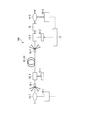
- It is a schematic diagram of an optical amplifier of a 1st embodiment of the present invention.
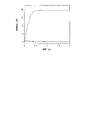
- 5 is a graph showing a change in gain with respect to elapsed time in the optical amplifier shown in FIG. 4.
- FIG. 8 is a schematic view of an optical amplifier including the amplification fiber shown in FIG. 6 or 7.
- 9 is a graph showing the relationship between the radius of the core and the power consumption ratio of the optical amplifier shown in FIG. 8 with respect to the conventional EDFA.
- 9 is a graph showing the relationship between the radius of the core and the relative refractive index difference of the amplification fiber shown in FIG. 6 or 7 for indicating the region that is satisfied by the relative refractive index difference.
- 9 is another graph showing the relationship between the core radius of the amplification fiber shown in FIG. 6 or FIG.
- FIG. 9 is a graph showing a change in gain with respect to elapsed time in the optical amplifier shown in FIG. 8.
- 6 is a graph showing a change in gain with respect to elapsed time in a conventional optical amplifier.
- the amplification fiber 51 of the first embodiment of the present invention is used as an amplification medium of an optical fiber amplifier, for example.
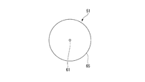
- the amplification fiber 51 is a so-called single-core erbium-doped fiber, which includes one core 61 and a clad 65 surrounding the core 61. Erbium ions are added to the core 61.
- the relative refractive index difference ⁇ n 51 between the core 61 and the clad 65 is limited to the area shaded in FIG. 2 or 3.
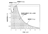
- the graph of FIG. 2 shows the relationship between the radius of the core and the relative refractive index difference ⁇ n 51 [%], which is numerically calculated assuming that the amplifying fiber 51 is applied to the amplification of C-band signal light.
- the graph of FIG. 3 represents the relationship between the radius of the core and the relative refractive index difference, which is numerically calculated assuming that the amplification fiber 51 is applied to the amplification of the signal light in the L band.
- the above-mentioned C band represents a wavelength band of 1530 nm or more and 1565 nm or less
- the L band represents a wavelength band of 1565 nm or more and 1625 nm or less.
- the gain change speed immediately after the change of the input signal light power needs to be less than 0.2 dB/ ⁇ s. There is. This is because the bandwidth of the feedback control circuit and the LD drive circuit is approximately 1 MHz.
- the speed of change in gain differs depending on the radius a [ ⁇ m] of the core 61 and the relative refractive index difference ⁇ n 51 .
- the difference (first relative refractive index difference) ⁇ n 1 is smaller than the boundary line 1-1 represented by the following equation (1).
- the amplification fiber 51 when the amplification fiber 51 is applied to the amplification of the signal light in the L band, as shown in FIG. 3, when the radius a increases from 1 ⁇ m, the gain change speed becomes 0.2 dB/ ⁇ s.
- the boundary line 1-2 of the relative refractive index difference (third relative refractive index difference) ⁇ n 3 is smaller than the boundary line 1-1 represented by the following equation (3).
- the gain change speed is substantially 0. It becomes 0.2 dB/ ⁇ s. If the relative refractive index difference ⁇ n 51 is fixed and the radius a is increased and the radius a becomes larger than a predetermined radius, the allowable mode of the core 61 becomes a higher order mode, and the amplification of the single mode signal light amplification by mode coupling. Efficiency is reduced.
- the above-mentioned predetermined radius varies depending on the relative refractive index difference ⁇ n 51 .
- the amplification fiber 51 is wound around the bobbin in a coil shape, and is adhered and fixed to the bobbin with an adhesive or the like. As a result, mechanical disturbance such as vibration of the amplifying fiber 51 due to air flow is avoided. In this way, by suppressing the mode conversion of the single-mode signal light into the higher-order mode during the propagation through the amplification fiber 51, the amplification fiber 51 can be effectively used when the cutoff wavelength is 2 ⁇ m or less. It can be handled as a single mode fiber (SMF).
- SMF single mode fiber
- the cutoff wavelength of the amplification fiber 51 becomes 2 ⁇ m as shown in FIG.
- the boundary line 2-1 of the relative refractive index difference (second relative refractive index difference) ⁇ n 2 is expressed by the following equation (2).
- the cutoff wavelength of the amplification fiber 51 is 2 ⁇ m.
- the boundary line 2-2 of the relative refractive index difference (fourth relative refractive index difference) ⁇ n 4 is expressed by the following equation (4).
- the relative refractive index difference ⁇ n 51 when the amplification fiber 51 is applied to the amplification of C-band signal light, the relative refractive index difference ⁇ n 51 is smaller than the relative refractive index difference ⁇ n 1 or the relative refractive index difference ⁇ n 2. Is less than or equal to the value of.
- the relative refractive index difference ⁇ n 51 when the amplification fiber 51 is applied to the amplification of the signal light in the L band, the relative refractive index difference ⁇ n 51 is equal to the relative refractive index difference ⁇ n 3 and the relative refractive index difference ⁇ n 4 . It is less than the smaller one.
- the relative refractive index difference ⁇ n 51 is limited to the regions shown by the hatching in FIGS. 2 and 3, respectively, the radius a and the relative refractive index difference ⁇ n are reduced.
- the correlation of 51 is limited to a region where the gain change value becomes a value that satisfies a predetermined reference value when the input signal light power changes.
- the predetermined reference value means a reference value that does not deteriorate the transmission characteristics of the optical network, and is, for example, less than 0.2 dB.
- the gain control is performed by the feedback control with respect to the change of the input signal light power due to the change of the wavelength number of the WDM signal light. At this time, the gain change can be suppressed to less than 0.2 dB.
- the boundary line 1-2 and the boundary line 2-2 intersect in a region of ⁇ n>2.8%.
- silica glass or tellurite glass or bismuth oxide glass which is a glass having a higher refractive index than silica glass
- the relative refractive index difference ⁇ n 51 is 2 in the region of the radius a where the boundary line 1-2 and the boundary line 2-2 intersect at ⁇ n>2.8%. It is below 8%.
- the optical amplifier 101 shown in FIG. 4 includes LD light sources (semiconductor laser light sources) 12-1 and 12-2, multiplexers/demultiplexers 13-1 and 13-2, and an optical branching device 14 in addition to the amplification fiber 51 described above. -1, 14-2, photodetectors 15-1, 15-2, gain equalizer 16, and feedback circuit 17 are provided.
- the LD light sources 12-1 and 12-2 emit the excitation light that is input to the amplification fiber 51.
- Each of the multiplexers/demultiplexers 13-1 and 13-2 incorporates an optical isolator (not shown), and multiplexes or demultiplexes the signal light and the pump light.
- the optical branching devices 14-1 and 14-2 branch a part of the input light.
- the photodetectors 15-1 and 15-2 convert the light split by the optical splitters 14-1 and 14-2 into a current or a voltage according to the power of the light.
- the gain equalizer 16 equalizes the wavelength dependence of the gain of the amplification fiber 51.
- the feedback circuit 17 calculates the gain using the detection results of the photodetectors 15-1 and 15-2, and generates an adjustment current (current) to be supplied to the LD light sources 12-1 and 12-2 from the calculation result. ..
- the feedback circuit 17 uses an LD so that the gain calculated from the detection values of the photodetectors 15-1 and 15-2 becomes constant when the input signal light power changes. This is done by adjusting the drive current to each of the light sources 12-1 and 12-2.
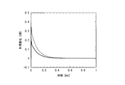
- the solid line in FIG. 5 indicates that in the optical amplifier 101 assuming that the radius a is 2 ⁇ m, the relative refractive index difference ⁇ n 51 is 0.8%, and the signal light is in the C band, the number of wavelengths of the signal light is 40 to 1
- the figure shows the state of gain control for the remaining one wavelength when the gain is changed to.
- the broken line of FIG. 5 uses, as a reference, an erbium-doped fiber having a radius a of 2 ⁇ m and a relative refractive index difference ⁇ n of 1.5% in place of the amplification fiber 51, and other conditions are represented by solid lines. A state of gain control of the optical amplifier 101 similar to the state is shown.
- the condition that the radius a is 2 ⁇ m and the relative refractive index difference ⁇ n 51 is 0.8% is in the shaded area in FIG. 2, but the radius a is 2 ⁇ m and the relative refractive index difference ⁇ n 51 is 1.5.
- the condition of% lies outside the shaded area of FIG. As shown by the solid line in FIG. 5, when the amplifying fiber 51 having the radius a of 2 ⁇ m and the relative refractive index difference ⁇ n 51 of 0.8% is used, the maximum value of the gain change is less than 0.2 dB.
- the gain change reaches a maximum of about 0.35 dB. From this result, according to the amplification fiber 51, when the gain control by the feedback control is performed with respect to the change in the input signal light power due to the change in the number of wavelengths of the WDM signal light, the gain change is less than 0.2 dB. It can be confirmed that it can be suppressed.
- the radius a is 3.5 ⁇ m
- the relative refractive index difference ⁇ n 51 is 0.8%.
- the pumping light power required for a gain of 25 dB was compared when the amplification fiber 51 was used and when an erbium-doped fiber having a radius a of 3.5 ⁇ m and a relative refractive index difference ⁇ n of 1.5% was used.
- the erbium-doped fiber having the radius a of 3.5 ⁇ m and the relative refractive index difference ⁇ n of 1.5% As a result, in the amplifying fiber 51 having the radius a of 3.5 ⁇ m and the relative refractive index difference ⁇ n 51 of 0.8%, the erbium-doped fiber having the radius a of 3.5 ⁇ m and the relative refractive index difference ⁇ n of 1.5%.
- the pump light power required was 9 times that of the fiber, and the cutoff wavelength exceeded 2 ⁇ m.
- the gain will be (+ ⁇ ) below the normal value under the blowing environment of 1 m/s. It fluctuated with time by about 0.8 dB.
- the (+-) represents a plus or minus sign.
- the gain does not change from the normal value when the above-described amplification fiber 51 is wound around the bobbin and adhered and fixed to the bobbin.
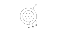
- the amplifying fiber 52 of the second embodiment of the present invention includes seven cores 61 arranged at equal intervals and a clad 65 surrounding the cores 61. ..
- the clad 65 includes a first clad (clad) 62 that surrounds the seven cores 61 without a gap, and a second clad 63 that surrounds the first clad 62.
- the refractive index of the first cladding 62 is lower than the refractive index of the core 61.
- the first cladding 62 propagates the excitation light, and the excitation light can collectively excite the erbium ions added to all the cores 61.
- the refractive index of the second cladding 63 is lower than the refractive index of the first cladding 62.
- the amplification fiber 52 is a multi-core erbium-doped fiber having a double clad structure.
- the relative refractive index differences ⁇ n 52 and ⁇ n 53 of the amplifying fibers 52 and 53 mean the relative refractive index difference between the core 61 and the first cladding 62, respectively.
- the amplifying fiber 53 shown in FIG. 7 is a modified example of the amplifying fiber 52, and is provided with 19 cores 61 arranged at equal intervals and a clad 65 surrounding these cores 61.
- the optical amplifier 102 shown in FIG. 8 includes LD light sources 12-1 and 12-2, multiplexers/demultiplexers 13-1 and 13-2, and an optical branching device 14-1 in addition to the amplification fiber 52 or the amplification fiber 53. , 14-2, photodetectors 15-1 and 15-2, a gain equalizer 16, and a feedback circuit 17. However, the feedback circuit 17 calculates the gain using the detection results of the photodetectors 15-1 and 15-2, but generates only the adjustment current to be supplied to the LD light source 12-2 from the calculation result as described later. Let
- the optical amplifier 102 further includes a fan-in component 18-1 and a fan-out component 18-2.
- the fan-in component 18-1 is provided between the multiplexer/demultiplexer 13-1 and the optical branching device 14-1 and converts a single-core fiber into a multi-core fiber.
- the fan-out component 18-2 is provided between the multiplexer/demultiplexer 13-2 and the end of the amplification fiber 52 or the amplification fiber 53 on the side opposite to the multiplexer/demultiplexer 13-1, and the multi-core to single Convert to core fiber.
- the LD light source 12-1 is a multimode LD.
- the pumping light of the LD light source 12-1 is coupled to the first cladding 62 of the amplifying fiber 52 or the amplifying fiber 53 via the multiplexer/demultiplexer 13-1 and used as the cladding pumping light.
- the LD light source 12-2 is a single mode LD.
- the pumping light of the LD light source 12-2 is multiplexed with the signal light by the multiplexer/demultiplexer 13-2, input to the core 61 of the amplifying fiber 52 or the amplifying fiber 53, and used as the core pumping light.
- the feedback circuit 17 drives the LD light source 12-2 so that the gain calculated from the detection values of the photodetectors 15-1 and 15-2 becomes constant when the input signal light power changes. This is done by adjusting only the current. At this time, the drive current of the LD light source 12-1 is kept constant.
- the multi-core EDFA using clad pumping has only one light source for clad pumping, and thus has the effect of lowering the power consumption of the optical amplifier.
- this low power consumption effect cannot be obtained when the core radius of the erbium-doped fiber becomes smaller than a predetermined radius. This is because when the radius of the core is small, the erbium ions added to the core cannot sufficiently absorb the pumping light propagating in the first cladding, and the pumping light power not used for amplification increases, and By increasing the power consumption.
- the radius of the boundary core that determines whether or not the low power consumption effect is present is 2.3 ⁇ m.
- the power consumption ratio of the conventional EDFA is plotted against the core radius.
- the power consumption ratio to the conventional EDFA is the power consumption of the amplifying fiber 52 or the amplifying fiber 53 as a multi-core EDFA using clad pumping, the power consumption of a single-core EDFA having the same amplification characteristic ⁇ the number of cores of the multi-core EDFA. It was calculated by dividing by.
- the solid line in FIG. 9 shows the calculation result of the power consumption of the amplification fiber 52.
- the broken line in FIG. 9 shows the result of calculation of the power consumption of the amplification fiber 53.
- the solid line and the broken line in FIG. 9 substantially overlap each other.
- the power consumption ratio of the amplification fibers 52 and 53 to the conventional EDFA is less than 1 when the radius a is 2.3 ⁇ m or more.
- the radius a is 2.3 ⁇ m or more, the amplification fiber 52 or the amplification fiber 53 has a low power consumption effect.
- the radius a at which a gain change speed of 0.2 dB/ ⁇ s is obtained and the restricted region of the relative refractive index differences ⁇ n 52 and ⁇ n 53 are shaded in FIGS. 2 and 3.
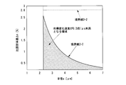
- the radius a is further limited to 2.3 ⁇ m or more from the formed region. That is, FIG. 10 shows a limiting region of the radius a and the relative refractive index differences ⁇ n 52 and ⁇ n 53 when the amplifying fiber 52 or the amplifying fiber 53 is applied to the amplification of the signal light in the C band.
- FIG. 10 shows a limiting region of the radius a and the relative refractive index differences ⁇ n 52 and ⁇ n 53 when the amplifying fiber 52 or the amplifying fiber 53 is applied to the amplification of the signal light in the C band.
- FIG. 11 shows a limiting region of the radius a and the relative refractive index differences ⁇ n 52 and ⁇ n 53 when the amplifying fiber 52 or the amplifying fiber 53 is applied to the amplification of signal light in the L band.
- the boundary line 1-2 is in the region where the radius a is less than 2.3 ⁇ m and is shaded. Does not appear in the restricted area of.
- the solid line in FIG. 12 indicates that the signal light is in the C band in the optical amplifier 102 using the amplifying fibers 52 and 53 having the radius a of 2.4 ⁇ m and the relative refractive index differences ⁇ n 52 and ⁇ n 53 of 1.7%. , The state of gain control for the remaining one wavelength when the number of wavelengths of the signal light changes from 40 to 1.
- the broken line in FIG. 12 is, as a reference, a gain control when an erbium-doped fiber having a radius a of 2.4 ⁇ m and a relative refractive index difference ⁇ n of 2.0% is used instead of the amplifying fibers 52 and 53. Is shown.
- the condition that the radius a is 2.4 ⁇ m and the relative refractive index differences ⁇ n 52 and ⁇ n 53 are 1.7% is within the shaded region shown in FIG.
- the condition that the radius a is 2.4 ⁇ m and the relative refractive index differences ⁇ n 52 and ⁇ n 53 are 2.0% is outside the shaded region shown in FIG.
- the maximum value of the gain change is less than 0.2 dB.
- the maximum value of the gain change is It is about 0.3 dB, which exceeds 0.2 dB. From this result, according to the amplification fibers 52 and 53, when the gain control by the feedback control is performed with respect to the change in the input signal light power due to the change in the number of wavelengths of the WDM signal light, the gain change is 0.2 dB. It can be seen that it can be kept below.
- amplification fibers 52 and 53 having a radius a of 3.5 ⁇ m and a relative refractive index difference ⁇ n 52 and ⁇ n 53 of 0.8% in a shaded area shown in FIG. 10 were used.
- the core pumping light power required for a gain change of 25 dB was compared between the case of using an erbium-doped fiber having a radius a of 3.5 ⁇ m and a relative refractive index difference ⁇ n of 1.5%.
- the radius a is 3.5 ⁇ m and the relative refractive index differences ⁇ n 52 and ⁇ n 53 are 0.8%.
- the core pumping light power of 7 times that of the amplifying fibers 52 and 53 is required, and the cutoff wavelength exceeds 2 ⁇ m.
- the gain is normal under a blowing environment of 1 m/s.
- the gain did not change from the normal value. Similar to the amplification fiber 51 of the first embodiment, it was confirmed that when the amplification fibers 52 and 53 were wound around the bobbin and adhered and fixed to the bobbin, the change in gain was suppressed.
- the gain changes rapidly even if the input signal light power changes rapidly. Without changing the gain, the change in gain can be suppressed to 0.2 dB or less.
- the preferred embodiments of the present invention have been described above, but the present invention is not limited to the above-mentioned embodiments.
- the configuration of the present invention can be modified within the range in which the above objects and effects can be achieved.
- the specific structure, shape, etc. when carrying out the present invention may be other structures, shapes, etc. within the range in which the objects and effects of the present invention can be achieved.
Landscapes
- Physics & Mathematics (AREA)
- Electromagnetism (AREA)
- Optics & Photonics (AREA)
- Engineering & Computer Science (AREA)
- Plasma & Fusion (AREA)
- General Physics & Mathematics (AREA)
- Lasers (AREA)
- Optical Fibers, Optical Fiber Cores, And Optical Fiber Bundles (AREA)
- Light Guides In General And Applications Therefor (AREA)
Abstract
エルビウムイオンが添加されたコアと、コアを囲み、コアの屈折率より低い屈折率を有するクラッドと、を備え、コアとクラッドとの比屈折率差Δn51は、コアの半径aに関する所定の式で表される比屈折率差Δn1及びコアの半径aに関する所定の式で表される比屈折率差Δn2のうち小さい方の値以下である。
Description
本発明は、光ファイバ増幅器の増幅媒体として適用可能な増幅用ファイバ及び光増幅器に関する。
大容量の光伝送システムでは、1本のファイバに互いに異なる複数の波長の信号光を多重して伝送する波長分割多重(Wavelength Division Multiplexing:WDM)伝送方式が採用されている。長距離のWDM伝送では、エルビウム添加ファイバ増幅器(Erbium Doped optical Fiber Amplifier:EDFA)が光中継装置に用いられ、伝送波長帯として1.5μm帯が用いられている。
WDM伝送方式を用いた光ネットワークでは、光ノード間距離の差によるスパンロスの差異があるだけではなく、ファイバへの接触、経年変化等によりスパンロスが変動し、光パス切り替え、設備の増設又は撤去、光通信ノードの障害等によりチャネル数が変更される。スパンロスの変動やチャネル数の変更は、光ネットワーク内で使用されるEDFAの入力信号光パワーを変化させる。WDM伝送で使用されるEDFAは、複数の波長の信号光を各々等しい利得で増幅させる必要があるので、伝送波長帯において利得の波長依存性が平坦になるように設計される。しかし、ある信号光の入力信号光パワーで利得の波長依存性が平坦である場合に、EDFAの入力信号光パワーが変化すると、EDFAの利得の波長依存性は平坦ではなくなり、利得チルトが生じる。利得チルトが生じると、十分な利得が得られない信号光や、利得が大きくなりすぎる信号光が生じ、光ネットワークの伝送特性が劣化する。したがって、WDM伝送方式を用いた光ネットワークで使用されるEDFAは、入力信号光パワーの変化に対して常に一定の利得で且つ利得の波長依存性が平坦であるように利得制御される必要がある。
EDFAの利得制御の方法の1つに、入力信号光パワーの増減に対して励起光パワーを増減し、入力信号光パワーに変化があっても常に利得の波長依存性を平坦な状態に保つ励起光パワー制御法がある。EDFAでは、励起光源として半導体レーザ(Laser Diode:LD)が用いられる。励起光パワーの増減は、フィードバック制御回路によってLDへの注入電流(LD駆動回路の駆動電流)を増減することによって行われる。
特に、WDM信号の波長数変化による入力信号光パワー変化に対しては、高速に励起光パワーを調整して、利得を高速に制御する必要がある。例えば、図13には、時間t=0でEDFAの入力信号光パワーが減少したとき、励起光パワーが一定である条件下である場合のEDFA利得の過渡応答(図13の破線)と、励起光パワー制御法による利得制御時の過渡応答(図13の実線)の数値計算例を示す。図13の破線で示すように、励起光パワーが一定である条件下では、急激な入力信号光パワーの減少により、EDFAの利得(図13の利得変化)は急激に増加する。一方、励起光パワー制御を行うことにより、EDFAの利得の急激な変化は、ある程度抑圧される。ところが、フィードバック制御回路とLD駆動回路は、有限の応答時間を有するため、入力信号光パワーの減少直後のEDFAの利得は急激に増加する。入力信号光パワーが急激に増加した場合は、EDFAの利得は急激に減少する。このようなEDFAの利得の急激な変化は、信号光パワーに急激な変化をもたらし、光ネットワークの伝送特性の劣化の原因となる。
例えば、非特許文献1に開示されている伝送システムでは入力信号光パワーの減少は15dB(即ち、32波→1波の変化)であり、非特許文献2に開示されている伝送システムでは入力信号光パワーの減少は16dB(即ち、40波→1波の変化)である。入力信号光パワーの減少量は互いに異なるが、非特許文献1,2に開示されている伝送システムでのEDFAの利得の変化は、1.0dB程度である。実現性の高いLD駆動回路のスループットは帯域1MHz且つ数タップで数100kHzといわれており、このようなスループットに対応するためには、EDFAの利得変化速度が0.2dB/μs程度を下回る必要がある。
光伝送システムの伝送容量を飛躍的に増大させるために、1本のファイバに複数のコアを有するマルチコアファイバを伝送路に用いたマルチコア光伝送システムの開発が進められている。マルチコアファイバの各コアに互いに異なる情報を伝送するWDM信号を伝搬させることによって、従来のように1本に1つのコアを有する単一コアファイバを伝送路として用いる場合に比べて、飛躍的に伝送容量を増大させることができる。長距離のマルチコア光伝送システムでは、伝送中に強度が低下した信号光を増幅するため、従来の単一コアファイバを伝送路として用いる光伝送システムと同様にマルチコアファイバEDFAが用いられている。
例えば、非特許文献3には、エルビウムイオンを添加した複数のコアと、径方向の内側の第1クラッドとその外側の第2クラッドとを有するダブルクラッド構造を備えたクラッド励起マルチコアファイバEDFAが開示されている、非特許文献3に開示されているクラッド励起マルチコアファイバEDFAでは、第1クラッドの屈折率がコアの屈折率より小さくなっている。また、非特許文献3に開示されているクラッド励起マルチコアファイバEDFAは、第2クラッドの屈折率より大きいダブルクラッドエルビウム添加ファイバと、1台の高出力マルチモード励起光源とを備えている。クラッド励起マルチコアファイバEDFAでは、単純にマルチモード励起光源の出力光パワーを調整しても、前述のような入力信号光パワーの変化時の利得制御が行えない。即ち、あるコアの入力信号光パワーが変化したとしても、他のコアの入力信号光パワーがあるコアの入力信号光パワーと同様に変化するとは限らない。そのため、非特許文献3に開示されているクラッド励起マルチコアファイバEDFAでは、あるコアの入力信号光パワーの変化に対して、マルチモード励起光源の出力光パワーを調整すると、入力信号光パワーが変化していないコアの利得が変化してしまうという問題があった。この問題を解決するために、例えば、非特許文献4には、クラッド励起用のマルチモード励起光源だけではなく、コア毎に信号光と励起光とを合波してエルビウムイオンを励起するためのコア励起光源を備えたクラッド励起マルチコアファイバEDFAが提案されている。
「高速制御機能付き小型アンプ」, 古河電工時報, 第116号, pp. 79-80 (平成17年7月).
杉本亮, 宮内秀徳, 島研介, 姫野邦治, 細谷英行, 堀内嘉明, 田中祥顕, 及川陽一, 志賀代康, 長枝浩, フジクラ技報, Vol. 1, No. 116, pp. 1-5, (2009年7月).
Y. Mimura, et al., "Batch Multicore Amplification with Cladding-Pumped Multicore EDF," ECOC 2012 Technical Digest, paper Tu.4.F.1 (2012).
M. Yamada et al., "Gain Control in Multi-Core Erbium/Ytterbium-Doped Fiber Amplifier with Hybrid Pumping," Proc. OECC 2016, paper WC1-2 (2016).
非特許文献4に開示されているクラッド励起マルチコアファイバEDFAによれば、利得制御が可能になるが、前述のLD駆動回路が有限の応答時間を有するために生じる利得の急激な変化が生じてしまうという課題は依然として残っている。
上述のように、従来の光ファイバ増幅器では、WDM信号の波長数の変化による入力信号光パワーの変化に対して、高速に励起光パワーを調整し、利得を高速に制御する必要があった。しかしながら、このようなEDFAの利得の急激な変化は、信号光パワーに急激な変化をもたらし、光ネットワークの伝送特性の劣化の原因となる。特に、近年開発されたマルチコアファイバEDFAでは、LD駆動回路が有限の応答時間を有するために生じる利得の急激な変化によって、入力信号光パワー変化時の利得制御が行えないという課題があった。また、カットオフ波長が信号光の波長近傍或いは信号光波長より長い場合、ファイバが送風の影響で揺れると、ファイバのコアで伝搬する光信号も揺らいでしまうという課題があった。
本発明は、上述の事情に鑑みてなされたもので、入力信号光パワーが急激に変化しても、利得を急激に変化させない、又は利得の変化を抑圧可能な増幅用ファイバ及び光増幅器を提供する。
本発明の増幅用ファイバは、エルビウムイオンが添加されたコアと、前記コアを囲み、前記コアの屈折率より低い屈折率を有するクラッドと、を備え、前記コアと前記クラッドとの比屈折率差は、以下の(1)式で表される第1比屈折率差及び以下の(2)式で表される第2比屈折率差のうち小さい方の値以下である。


なお、上述の(1)及び(2)において、aは前記コアの半径[μm]を表し、Δn1は前記第1比屈折率差[%]を表し、Δn2は前記第2比屈折率差[%]を表す。
本発明の増幅用ファイバでは、前記コアは互いに間隔をあけて複数設けられ、複数の前記コアと前記クラッドとの各比屈折率差は、前記第1比屈折率差及び前記第2比屈折率差のうち小さい方の値以下であり、前記コアの半径は(5)式を満たしてもよい。

本発明の増幅用ファイバでは、前記第1屈折率差及び前記第2比屈折率差のうち小さい方の値が2.8%より大きくなる前記コアの半径の領域では、前記コアと前記クラッドとの比屈折率差は2.8%以下であってもよい。
本発明の増幅用ファイバは、エルビウムイオンが添加されたコアと、前記コアを囲み、前記コアの屈折率より低い屈折率を有するクラッドと、を備え、前記コアと前記クラッドとの比屈折率差は、以下の(3)式で表される第3比屈折率差及び以下の(4)式で表される第4比屈折率差のうち小さい方の値以下である。


なお、上述の(3)及び(4)において、aは前記コアの半径[μm]を表し、Δn3は前記第3比屈折率差[%]を表し、Δn4は前記第4比屈折率差[%]を表す。
本発明の増幅用ファイバでは、前記コアは互いに間隔をあけて複数設けられ、複数の前記コアと前記クラッドとの各比屈折率差は、前記第3比屈折率差及び前記第4比屈折率差のうち小さい方の値以下であり、前記コアの半径は(5)式を満たしてもよい。

本発明の増幅用ファイバでは、前記第3屈折率差及び前記第4比屈折率差のうち小さい方の値が2.8%より大きくなる前記コアの半径の領域では、前記コアと前記クラッドとの比屈折率差は2.8%以下であってもよい。
本発明の増幅用ファイバでは、前記クラッドは、複数の前記コアを囲み、前記コアの屈折率より低い屈折率を有する第1クラッドと、前記第1クラッドを囲み、前記第1クラッドの屈折率より低い屈折率を有する第2クラッドと、を有してもよい。
本発明の増幅用ファイバは、ボビンに巻き取られ、前記ボビンに接着されていてもよい。
本発明の光増幅器は、上述の増幅用ファイバと、前記増幅用ファイバに入力する励起光を発する半導体レーザ光源と、前記増幅用ファイバに入力される信号光及び前記増幅用ファイバから出力される信号光のパワーに応じて検出される利得から前記半導体レーザ光源に供給する電流を発生させるフィードバック回路と、を備える。
本発明によれば、入力信号光パワーが急激に変化しても、利得を急激に変化させない、又は利得の変化を抑圧可能な増幅用ファイバ及び光増幅器を提供できる。
以下、図面を参照して本発明の増幅用ファイバ及び光増幅器の実施形態について説明する。なお、本明細書及び図面において、同一の機能を有する構成には同一の符号を付し、繰り返しの説明は省略する。
[第1実施形態]
本発明の第1実施形態の増幅用ファイバ51は、例えば光ファイバ増幅器の増幅媒体として用いられる。図1に示すように、増幅用ファイバ51は、1個のコア61と、コア61を囲むクラッド65とを備え、所謂シングルコア・エルビウム添加ファイバである。コア61には、エルビウムイオンが添加されている。
本発明の第1実施形態の増幅用ファイバ51は、例えば光ファイバ増幅器の増幅媒体として用いられる。図1に示すように、増幅用ファイバ51は、1個のコア61と、コア61を囲むクラッド65とを備え、所謂シングルコア・エルビウム添加ファイバである。コア61には、エルビウムイオンが添加されている。
コア61とクラッド65との比屈折率差Δn51は、図2又は図3において網掛けで図示されている領域内に制限されている。図2のグラフは、増幅用ファイバ51をC帯の信号光の増幅に適用する場合を想定して数値計算された、コアの半径と比屈折率差Δn51[%]との関係を表している。図3のグラフは、増幅用ファイバ51をL帯の信号光の増幅に適用する場合を想定して数値計算された、コアの半径と比屈折率差との関係を表している。上述のC帯は1530nm以上1565nm以下の波長帯を表し、L帯は1565nm以上1625nm以下の波長帯を表す。なお、半径aが1μmより小さくなると、エルビウム添加ファイバの増幅に必要なファイバ長が極端に長くなる。このことから、1μmより半径aが小さいエルビウム添加ファイバは略使用されないため、図2及び図3のグラフでは半径aが1μm以下である場合は図示されていない。
増幅用ファイバ51における入力信号光パワーの変化に対して、利得の変化を0.2dB未満に抑えるためには、入力信号光パワーの変化直後の利得変化速度が0.2dB/μs未満である必要がある。このことは、フィードバック制御回路及びLD駆動回路の帯域が概ね1MHzであることによる。利得変化速度は、コア61の半径a[μm]と比屈折率差Δn51によって異なる。増幅用ファイバ51がC帯の信号光の増幅に適用されるとき、図2に示すように、半径aが1μmから増加していくと、利得変化速度が0.2dB/μsとなる比屈折率差(第1比屈折率差)Δn1は、次に示す(1)式で表される境界線1-1より小さい領域となる。

同様に、増幅用ファイバ51がL帯の信号光の増幅に適用されるとき、図3に示すように、半径aが1μmから増加していくと、利得変化速度が0.2dB/μsとなる比屈折率差(第3比屈折率差)Δn3の境界線1-2は、次に示す(3)式で表される境界線1-1より小さい領域となる。

C帯において比屈折率差Δn51が比屈折率差Δn1より小さい領域、及びL帯において比屈折率差Δn51が後述する比屈折率差Δn2より小さい領域では、利得変化速度は略0.2dB/μsとなる。比屈折率差Δn51を固定して半径aを増大させた場合、所定の半径より半径aが大きくなると、コア61の許容モードが高次モードとなり、モード結合によってシングルモードの信号光増幅の増幅効率が低下する。前述の所定の半径は、比屈折率差Δn51によって変動する。しかしながら、増幅用ファイバ51と光増幅器を構成するピグテイルファイバ(図示略)との融着接続において、コア61の中心とピグテイルファイバのコアの中心とを合わせるように融着接続することにより、増幅用ファイバ51の入力端で高次モード光の励振が抑えられる。
また、増幅用ファイバ51はボビンにコイル状に巻き付けられ、接着剤等でボビンに接着及び固定されている。このことによって、例えば送風による増幅用ファイバ51の振動等の機械的擾乱が回避される。このようにしてシングルモードの信号光が増幅用ファイバ51を伝搬中に高次モードにモード変換されることを抑圧することによって、カットオフ波長が2μm以下であるときには増幅用ファイバ51を実効的にシングルモードファイバ(Single Mode Fiber:SMF)として取り扱うことができる。
半径aが前述の所定の半径より大きい領域において、増幅用ファイバ51がC帯の信号光の増幅に適用されるとき、図2に示すように、増幅用ファイバ51のカットオフ波長が2μmとなる比屈折率差(第2比屈折率差)Δn2の境界線2-1は、次に示す(2)式で表される。

同じく、半径aが前述の所定の半径より大きい領域において、増幅用ファイバ51がL帯の信号光の増幅に適用されるとき、図3に示すように、増幅用ファイバ51のカットオフ波長が2μmとなる比屈折率差(第4比屈折率差)Δn4の境界線2-2は、次に示す(4)式で表される。

図2からわかるように、増幅用ファイバ51がC帯の信号光の増幅に適用されるとき、比屈折率差Δn51は、比屈折率差Δn1及び比屈折率差Δn2のうち小さい方の値以下になっている。同様に、図3からわかるように、増幅用ファイバ51がL帯の信号光の増幅に適用されるとき、比屈折率差Δn51は、比屈折率差Δn3及び比屈折率差Δn4のうち小さい方の値以下になっている。なお、比屈折率差Δn1と比屈折率差Δn2が互いに同一の値になる場合、及び比屈折率差Δn3と比屈折率差Δn4が互いに同一の値になる場合は、前述の「小さい方の値」は、互いに同一になった値を意味する。
上述の増幅用ファイバ51によれば、比屈折率差Δn51が図2及び図3のそれぞれにおいて網掛けで図示されている領域内に制限されていることによって、半径a及び比屈折率差Δn51の相関関係は、入力信号光パワーの変化の際に利得変化値が所定の基準値を満たす値となる領域に制限される。ここで、所定の基準値とは、光ネットワークの伝送特性を劣化させない基準値を意味し、例えば0.2dB未満である。半径a及び比屈折率差Δn51の相関関係が前述のように制限されることによって、WDM信号光の波長数の変化による入力信号光パワーの変化に対して、フィードバック制御による利得制御を行った際に、利得変化を0.2dB未満に抑えることができる。
なお、図3では、境界線1-2と境界線2-2はΔn>2.8%の領域で交わる。しかしながら、石英ガラスや石英ガラスより高い屈折率を有するガラスであるテルライトガラスまたは酸化ビスマスガラスを用いたとしても、ガラスファイバでΔn51>2.8%は実現困難である。このことから、増幅用ファイバ51の実用性を考慮すると、境界線1-2と境界線2-2がΔn>2.8%で交わる半径aの領域では、比屈折率差Δn51は、2.8%以下になっている。図2及び図3には、Δn=2.8%との条件が満たすべき比屈折率Δn5の境界線3-1,3-2として図示されている。
図4に示す光増幅器101は、上述の増幅用ファイバ51に加えて、LD光源(半導体レーザ光源)12-1,12-2、合分波器13-1,13-2、光分岐器14-1,14-2、光検出器15-1,15-2、利得等化器16、フィードバック回路17を備えている。LD光源12-1,12-2は、増幅用ファイバ51に入力する励起光を発する。合分波器13-1,13-2は、不図示の光アイソレータを内蔵し、信号光と励起光とを合波又は分波する。光分岐器14-1,14-2は、入力された光の一部を分岐する。
光検出器15-1,15-2は、光分岐器14-1,14-2によって分岐された光をその光のパワーに応じて電流又は電圧に変換する。利得等化器16は、増幅用ファイバ51の利得の波長依存性を等化する。フィードバック回路17は、光検出器15-1,15-2での検出結果を用いて利得を演算し、演算結果からLD光源12-1,12-2に供給する調整電流(電流)を発生させる。
光検出器15-1,15-2は、光分岐器14-1,14-2によって分岐された光をその光のパワーに応じて電流又は電圧に変換する。利得等化器16は、増幅用ファイバ51の利得の波長依存性を等化する。フィードバック回路17は、光検出器15-1,15-2での検出結果を用いて利得を演算し、演算結果からLD光源12-1,12-2に供給する調整電流(電流)を発生させる。
光増幅器101における利得制御は、入力信号光パワーが変化したときに、光検出器15-1,15-2のそれぞれの検出値から演算される利得が一定となるように、フィードバック回路17がLD光源12-1,12-2のそれぞれへの駆動電流を調整することによって、行われる。
図5の実線は、半径aが2μm、比屈折率差Δn51が0.8%であって、信号光がC帯であると想定した光増幅器101において、信号光の波長数が40から1に変化したときの、残った1波長の利得制御の様子を示している。図5の破線は、参照として、増幅用ファイバ51に替えて、半径aが2μm、比屈折率差Δnが1.5%のエルビウム添加ファイバを用いて、その他の条件は実線で表されている様子と同様にした光増幅器101の利得制御の様子を示している。半径aが2μm且つ比屈折率差Δn51が0.8%であるという条件は図2の網掛けされた領域内にあるが、半径aが2μm且つ仮に比屈折率差Δn51が1.5%であるという条件は図2の網掛けされた領域外にある。図5の実線で示すように、半径aが2μm且つ比屈折率差Δn51が0.8%である増幅用ファイバ51を用いた場合、利得変化の最大値が0.2dBを下回っている。一方、半径aが2μm、比屈折率差Δnが1.5%のエルビウム添加ファイバを用いた場合は利得変化が最大で約0.35dBに達することがわかる。この結果から、増幅用ファイバ51によれば、WDM信号光の波長数の変化による入力信号光パワーの変化に対して、フィードバック制御による利得制御を行った際に、利得変化を0.2dB未満に抑えられることを確認できる。
また、光増幅器101において信号光がC帯である構成において、図2で網掛された領域内にある条件を満たし、半径aが3.5μm、比屈折率差Δn51が0.8%である増幅用ファイバ51を用いた場合と、半径aが3.5μm、比屈折率差Δnが1.5%であるエルビウム添加ファイバを用いた場合に、利得25dBに必要な励起光パワーを比較した。その結果、半径aが3.5μm、比屈折率差Δn51が0.8%である増幅用ファイバ51では、半径aが3.5μm、比屈折率差Δnが1.5%であるエルビウム添加ファイバの9倍の励起光パワーが必要となり、カットオフ波長が2μmを超えた。
さらに、半径aが3.5μm、比屈折率差Δn51が0.8%である増幅用ファイバ51をボビンに巻き付けだけでは、1m/sの送風環境下において利得が正常値から(+-)0.8dB程、時間的に変動した。前記(+-)は、プラスマイナスの記号を表している。これに対し、上述の増幅用ファイバ51をボビンに巻き付けてボビンに接着及び固定した場合は、利得が正常値から変化しないことが確認された。
[第2実施形態]
本発明の第2実施形態の増幅用ファイバ52は、図6に示すように、互いに等間隔をあけて配置された7個のコア61と、これらのコア61を囲むクラッド65とを備えている。クラッド65は、7個のコア61を隙間なく囲む第1クラッド(クラッド)62と、第1クラッド62を囲む第2クラッド63と、を備えている。
本発明の第2実施形態の増幅用ファイバ52は、図6に示すように、互いに等間隔をあけて配置された7個のコア61と、これらのコア61を囲むクラッド65とを備えている。クラッド65は、7個のコア61を隙間なく囲む第1クラッド(クラッド)62と、第1クラッド62を囲む第2クラッド63と、を備えている。
第1クラッド62の屈折率は、コア61の屈折率より低い。第1クラッド62は、励起光を伝搬し、その励起光により全てのコア61に添加されたエルビウムイオンを一括して励起できる。第2クラッド63の屈折率は、第1クラッド62の屈折率より低い。増幅用ファイバ52は、ダブルクラッド構造のマルチコア・エルビウム添加ファイバである。増幅用ファイバ52,53の比屈折率差Δn52,Δn53はそれぞれ、コア61と第1クラッド62との比屈折率差を意味する。
図7に示す増幅用ファイバ53は、増幅用ファイバ52の変形例であり、互いに等間隔をあけて配置された19個のコア61と、これらのコア61を囲むクラッド65とを備えている。
図8に示す光増幅器102は、増幅用ファイバ52又は増幅用ファイバ53に加えて、LD光源12-1,12-2、合分波器13-1,13-2、光分岐器14-1,14-2、光検出器15-1,15-2、利得等化器16、フィードバック回路17を備えている。但し、フィードバック回路17は、光検出器15-1,15-2での検出結果を用いて利得を演算するが、後述するように演算結果からLD光源12-2に供給する調整電流のみを発生させる。
光増幅器102は、ファンイン部品18-1及びファンアウト部品18-2をさらに備えている。ファンイン部品18-1は、合分波器13-1と光分岐器14-1との間に設けられ、シングルコアファイバからマルチコアへ変換する。ファンアウト部品18-2は、増幅用ファイバ52又は増幅用ファイバ53の合分波器13-1とは反対側の端部と合分波器13-2との間に設けられ、マルチコアからシングルコアファイバへ変換する。LD光源12-1はマルチモードLDである。LD光源12-1の励起光は、合分波器13-1を介して増幅用ファイバ52又は増幅用ファイバ53の第1クラッド62に結合し、クラッド励起光として用いられる。一方、LD光源12-2は、シングルモードLDである。LD光源12-2の励起光は、合分波器13-2によって信号光と合波され、増幅用ファイバ52又は増幅用ファイバ53のコア61に入力され、コア励起光として用いられる。利得制御は、入力信号光パワーが変化したときに、光検出器15-1,15-2の検出値から演算される利得が一定となるようにフィードバック回路17がLD光源12-2への駆動電流のみを調整することによって、行われる。このとき、LD光源12-1の駆動電流は、一定に保持される。
クラッド励起を用いたマルチコアEDFAは、クラッド励起の光源が1つで済むため、光増幅器の消費電力を低下できる低消費電力効果を奏する。しかしながら、この低消費電力効果はエルビウム添加ファイバのコアの半径が所定の半径より小さくなると得られない。これは、コアの半径が小さいと、コアに添加されたエルビウムイオンが第1クラッドを伝搬する励起光を十分に吸収することができず、増幅に使用されない励起光パワーが増大し、光増幅器の消費電力を上昇させることによる。低消費電力効果の有無を決める境界のコアの半径は、2.3μmとなる。図9は、低消費電力効果の有無の境界が半径a=2.3μmにあることの根拠を示している。
図9に示すように、従来のEDFAに対する消費電力比をコア半径に対してプロットしたものである。従来のEDFAに対する消費電力比は、クラッド励起を用いたマルチコアEDFAとしての増幅用ファイバ52又は増幅用ファイバ53の消費電力を、同等の増幅特性を有するシングルコアEDFAの消費電力×マルチコアEDFAのコア数で除算することで算出した。図9の実線は、増幅用ファイバ52の消費電力について算出した結果を示す。図9の破線は、増幅用ファイバ53の消費電力について算出した結果を示す。図9の実線と破線は、互いに略重なっている。増幅用ファイバ52,53の従来のEDFAに対する消費電力比は共に、半径aが2.3μm以上で1を下回っている。半径aが2.3μm以上であるときに、増幅用ファイバ52又は増幅用ファイバ53が低消費電力効果を奏することになる。
したがって、増幅用ファイバ52又は増幅用ファイバ53において、0.2dB/μsの利得変化速度が得られる半径aと比屈折率差Δn52,Δn53の制限領域は、図2及び図3で網掛けされた領域から、図10及び図11に示すように、さらに半径aが2.3μm以上の制限を受ける。即ち、図10は、増幅用ファイバ52又は増幅用ファイバ53がC帯の信号光の増幅に適用される場合の半径aと比屈折率差Δn52,Δn53の制限領域を表している。図11は、増幅用ファイバ52又は増幅用ファイバ53がL帯の信号光の増幅に適用される場合の半径aと比屈折率差Δn52,Δn53の制限領域を示している。図11に示すように、増幅用ファイバ52又は増幅用ファイバ53がL帯の信号光の増幅に適用される場合、境界線1-2は半径aが2.3μm未満の領域にあり、網掛けの制限領域には現れない。
図12の実線は、半径aが2.4μmであり、且つ比屈折率差Δn52,Δn53が1.7%である増幅用ファイバ52,53を用いた光増幅器102で信号光がC帯であるとした場合、信号光の波長数が40から1に変化したときの残った1波長の利得制御の様子を示している。図12の破線は、参照として、増幅用ファイバ52,53に替えて、半径aが2.4μmであり、且つ比屈折率差Δnが2.0%のエルビウム添加ファイバを用いた場合の利得制御の様子を示している。半径aが2.4μmであり、且つ比屈折率差Δn52,Δn53が1.7%であるという条件は、図10に示す網掛けの領域内にある。しかしながら、半径aが2.4μmであり、且つ比屈折率差Δn52,Δn53が2.0%であるという条件は、図10に示す網掛けの領域外にある。図12に実線で示すように、増幅用ファイバ52,53を用いた場合は利得変化の最大値が0.2dBを下回っている。一方、図12に破線で示すように、半径aが2.4μmであり、且つ比屈折率差Δn52,Δn53が2.0%のエルビウム添加ファイバを用いた場合は利得変化の最大値が約0.3dBになり、0.2dBを上回っている。この結果から、増幅用ファイバ52,53によれば、WDM信号光の波長数の変化による入力信号光パワーの変化に対して、フィードバック制御による利得制御を行った際に、利得変化を0.2dB未満に抑えられることがわかる。
光増幅器102の構成において、図10に示す網掛けの領域内の半径aが3.5μm、且つ比屈折率差Δn52,Δn53が0.8%である増幅用ファイバ52,53を用いた場合と、半径aが3.5μm、且つ比屈折率差Δnが1.5%であるエルビウム添加ファイバを用いた場合に、25dBの利得変化に必要なコア励起光パワーを比較した。その結果、半径aが3.5μm、且つ比屈折率差Δnが1.5%であるエルビウム添加ファイバでは、半径aが3.5μm、且つ比屈折率差Δn52,Δn53が0.8%である増幅用ファイバ52,53の7倍ものコア励起光パワーが必要になり、カットオフ波長が2μmを超えた。さらに、半径aが3.5μm、且つ比屈折率差Δn52,Δn53が0.8%である増幅用ファイバ52,53をボビンに巻き付けだけでは、1m/sの送風環境下において利得が正常値から±0.8dB程、時間的に変動した。これに対し、上述の増幅用ファイバ52,53をボビンに巻き付け、ボビンに接着及び固定したものを用いた場合には、利得が正常値から変化しなかった。第1実施形態の増幅用ファイバ51と同様に、増幅用ファイバ52,53をボビンに巻き付けてボビンに接着及び固定した場合は、利得の変化が抑えられることが確認された。
上述のように、第1実施形態及び第2実施形態の増幅用ファイバ51,52,53及び光増幅器101,102によれば、入力信号光パワーが急激に変化しても、利得を急激に変化させず、利得の変化を0.2dB以下に抑圧できる。
以上、本発明の好適な実施形態について説明したが、本発明は上述の実施形態に限定されない。本発明の構成は、上述の目的及び効果を達成できる範囲内で変更可能である。また、本発明を実施する際における具体的な構造及び形状等は、本発明の目的及び効果を達成できる範囲内において、他の構造や形状等としてもよい。
51,52,53…増幅用ファイバ
61…コア
62…第1クラッド(クラッド)
65…クラッド
101,102…光増幅器
a…半径
Δn51,Δn52,Δn53…比屈折率差
61…コア
62…第1クラッド(クラッド)
65…クラッド
101,102…光増幅器
a…半径
Δn51,Δn52,Δn53…比屈折率差
Claims (9)
- エルビウムイオンが添加されたコアと、
前記コアを囲み、前記コアの屈折率より低い屈折率を有するクラッドと、
を備え、
前記コアと前記クラッドとの比屈折率差は、以下の(1)式で表される第1比屈折率差及び(2)式で表される第2比屈折率差のうち小さい方の値以下である、
増幅用ファイバ。


- 前記コアは互いに間隔をあけて複数設けられ、
複数の前記コアと前記クラッドとの各比屈折率差は、前記第1比屈折率差及び前記第2比屈折率差のうち小さい方の値以下であり、
前記コアの半径は(5)式を満たす、
請求項1に記載の増幅用ファイバ。

- 前記第1比屈折率差及び前記第2比屈折率差のうち小さい方の値が2.8%より大きくなる前記コアの半径の領域では、前記コアと前記クラッドとの比屈折率差は2.8%以下である、
請求項1または2に記載の増幅用ファイバ。 - エルビウムイオンが添加されたコアと、
前記コアを囲み、前記コアの屈折率より低い屈折率を有するクラッドと、
を備え、
前記コアと前記クラッドとの比屈折率差は、以下の(3)式で表される第3比屈折率差及び以下の(4)式で表される第4比屈折率差のうち小さい方の値以下である、
増幅用ファイバ。


- 前記コアは互いに間隔をあけて複数設けられ、
複数の前記コアと前記クラッドとの各比屈折率差は、前記第3比屈折率差及び前記第4比屈折率差のうち小さい方の値以下であり、
前記コアの半径は(5)式を満たす、
請求項4に記載の増幅用ファイバ。

- 前記第3比屈折率差及び前記第4比屈折率差のうち小さい方の値が2.8%より大きくなる前記コアの半径の領域では、前記コアと前記クラッドとの比屈折率差は2.8%以下である、
請求項4または5に記載の増幅用ファイバ。 - 前記クラッドは、
複数の前記コアを囲み、前記コアの屈折率より低い屈折率を有する第1クラッドと、
前記第1クラッドを囲み、前記第1クラッドの屈折率より低い屈折率を有する第2クラッドと、
を有する、
請求項2,3,5,6のいずれか一項に記載の増幅用ファイバ。 - ボビンに巻き取られ、
前記ボビンに接着されている、
請求項1から7のいずれか一項に記載の増幅用ファイバ。 - 請求項1から8のいずれか一項に記載の増幅用ファイバと、
前記増幅用ファイバに入力する励起光を発する半導体レーザ光源と、
前記増幅用ファイバに入力される信号光及び前記増幅用ファイバから出力される信号光のパワーに応じて検出される利得から前記半導体レーザ光源に供給する電流を発生させるフィードバック回路と、
を備える、
光増幅器。
Priority Applications (1)
| Application Number | Priority Date | Filing Date | Title |
|---|---|---|---|
| US17/427,248 US12099235B2 (en) | 2019-02-06 | 2020-01-30 | Amplifying fiber and optical amplifier |
Applications Claiming Priority (2)
| Application Number | Priority Date | Filing Date | Title |
|---|---|---|---|
| JP2019-019845 | 2019-02-06 | ||
| JP2019019845A JP2020126973A (ja) | 2019-02-06 | 2019-02-06 | 増幅用ファイバ及び光増幅器 |
Publications (1)
| Publication Number | Publication Date |
|---|---|
| WO2020162327A1 true WO2020162327A1 (ja) | 2020-08-13 |
Family
ID=71947513
Family Applications (1)
| Application Number | Title | Priority Date | Filing Date |
|---|---|---|---|
| PCT/JP2020/003499 Ceased WO2020162327A1 (ja) | 2019-02-06 | 2020-01-30 | 増幅用ファイバ及び光増幅器 |
Country Status (3)
| Country | Link |
|---|---|
| US (1) | US12099235B2 (ja) |
| JP (1) | JP2020126973A (ja) |
| WO (1) | WO2020162327A1 (ja) |
Cited By (3)
| Publication number | Priority date | Publication date | Assignee | Title |
|---|---|---|---|---|
| WO2024038491A1 (ja) * | 2022-08-15 | 2024-02-22 | 日本電信電話株式会社 | 増幅用光ファイバ及びクラッド励起型光ファイバ増幅器 |
| US12077713B2 (en) | 2020-09-28 | 2024-09-03 | Chevron Phillips Chemical Company Lp | Circular chemicals or polymers from pyrolyzed plastic waste and the use of mass balance accounting to allow for crediting the resultant products as circular |
| WO2025074582A1 (ja) * | 2023-10-05 | 2025-04-10 | 日本電気株式会社 | マルチコアファイバ増幅器、光増幅方法及び記録媒体 |
Families Citing this family (1)
| Publication number | Priority date | Publication date | Assignee | Title |
|---|---|---|---|---|
| JP2023019510A (ja) * | 2021-07-29 | 2023-02-09 | 横河電機株式会社 | 光ファイバ特性測定システム |
Citations (6)
| Publication number | Priority date | Publication date | Assignee | Title |
|---|---|---|---|---|
| JPH0926379A (ja) * | 1995-07-12 | 1997-01-28 | Fujitsu Ltd | 光増幅器のモニター構造 |
| JP2002141586A (ja) * | 2000-10-31 | 2002-05-17 | Nippon Telegr & Teleph Corp <Ntt> | 光増幅用テルライト光ファイバまたは光導波路または光増幅器 |
| JP2002158384A (ja) * | 2000-09-07 | 2002-05-31 | Sumitomo Electric Ind Ltd | 増幅用光ファイバ、光ファイバ増幅器、光送信器及び光通信システム |
| US20140036348A1 (en) * | 2012-07-31 | 2014-02-06 | Corning Incorporated | Few mode rare earth doped optical fibers for optical amplifiers, and amplifiers using such fibers |
| JP2015090969A (ja) * | 2013-11-07 | 2015-05-11 | 古河電気工業株式会社 | 光増幅装置 |
| JP2017021070A (ja) * | 2015-07-07 | 2017-01-26 | 日本電信電話株式会社 | マルチコア光ファイバ及び光増幅器 |
Family Cites Families (13)
| Publication number | Priority date | Publication date | Assignee | Title |
|---|---|---|---|---|
| AUPP218198A0 (en) * | 1998-03-04 | 1998-03-26 | University Of Sydney, The | Ultra-broadband low-noise gain-flattened rare-earth-doped fibre amplifier |
| US6538807B2 (en) | 2000-09-07 | 2003-03-25 | Sumitomo Electric Industries, Ltd. | Amplification optical fiber, fiber optic amplifier, optical transmitter, and optical communication system |
| US6611648B2 (en) * | 2001-05-09 | 2003-08-26 | Corning Incorporated | Optical fibers having cores with different propagation constants, and methods of manufacturing same |
| DK2765661T3 (en) * | 2011-10-04 | 2019-03-18 | Furukawa Electric Co Ltd | MULTI-CORN OPTICAL AMPLIFIER FIBER AND MULTI-CORN OPTICAL FIBER AMPLIFIER. |
| US9263846B2 (en) * | 2011-10-05 | 2016-02-16 | University Of Central Florida Research Foundation, Inc. | Systems and methods for amplifying space-multiplexed optical signals |
| US9025239B2 (en) * | 2011-12-13 | 2015-05-05 | Ofs Fitel, Llc | Multi-core erbium-doped fiber amplifier |
| CN104145198B (zh) * | 2012-02-29 | 2018-06-15 | 住友电气工业株式会社 | 多芯光纤、多芯光纤缆线以及多芯光纤传输系统 |
| JP5823448B2 (ja) * | 2013-06-21 | 2015-11-25 | 古河電気工業株式会社 | 増幅用マルチコア光ファイバデバイスおよびマルチコア光ファイバ増幅器 |
| US9231365B1 (en) * | 2014-06-12 | 2016-01-05 | Ofs Fitel, Llc | Discrete raman amplifier |
| US9698557B2 (en) * | 2015-03-09 | 2017-07-04 | Fujikura Ltd. | Optical fiber for amplification and optical fiber amplifier using the same |
| JP2017041515A (ja) * | 2015-08-18 | 2017-02-23 | 株式会社フジクラ | 増幅用光ファイバ及びそれを用いた光ファイバ増幅器 |
| EP3457183B1 (en) * | 2016-05-12 | 2020-06-10 | Sumitomo Electric Industries, Ltd. | Multicore optical fiber, fiber bragg grating, and method for manufacturing a fiber bragg grating |
| JP2018198287A (ja) * | 2017-05-24 | 2018-12-13 | 日本電信電話株式会社 | 増幅用ファイバ |
-
2019
- 2019-02-06 JP JP2019019845A patent/JP2020126973A/ja active Pending
-
2020
- 2020-01-30 WO PCT/JP2020/003499 patent/WO2020162327A1/ja not_active Ceased
- 2020-01-30 US US17/427,248 patent/US12099235B2/en active Active
Patent Citations (6)
| Publication number | Priority date | Publication date | Assignee | Title |
|---|---|---|---|---|
| JPH0926379A (ja) * | 1995-07-12 | 1997-01-28 | Fujitsu Ltd | 光増幅器のモニター構造 |
| JP2002158384A (ja) * | 2000-09-07 | 2002-05-31 | Sumitomo Electric Ind Ltd | 増幅用光ファイバ、光ファイバ増幅器、光送信器及び光通信システム |
| JP2002141586A (ja) * | 2000-10-31 | 2002-05-17 | Nippon Telegr & Teleph Corp <Ntt> | 光増幅用テルライト光ファイバまたは光導波路または光増幅器 |
| US20140036348A1 (en) * | 2012-07-31 | 2014-02-06 | Corning Incorporated | Few mode rare earth doped optical fibers for optical amplifiers, and amplifiers using such fibers |
| JP2015090969A (ja) * | 2013-11-07 | 2015-05-11 | 古河電気工業株式会社 | 光増幅装置 |
| JP2017021070A (ja) * | 2015-07-07 | 2017-01-26 | 日本電信電話株式会社 | マルチコア光ファイバ及び光増幅器 |
Cited By (3)
| Publication number | Priority date | Publication date | Assignee | Title |
|---|---|---|---|---|
| US12077713B2 (en) | 2020-09-28 | 2024-09-03 | Chevron Phillips Chemical Company Lp | Circular chemicals or polymers from pyrolyzed plastic waste and the use of mass balance accounting to allow for crediting the resultant products as circular |
| WO2024038491A1 (ja) * | 2022-08-15 | 2024-02-22 | 日本電信電話株式会社 | 増幅用光ファイバ及びクラッド励起型光ファイバ増幅器 |
| WO2025074582A1 (ja) * | 2023-10-05 | 2025-04-10 | 日本電気株式会社 | マルチコアファイバ増幅器、光増幅方法及び記録媒体 |
Also Published As
| Publication number | Publication date |
|---|---|
| JP2020126973A (ja) | 2020-08-20 |
| US20220120960A1 (en) | 2022-04-21 |
| US12099235B2 (en) | 2024-09-24 |
Similar Documents
| Publication | Publication Date | Title |
|---|---|---|
| US6826335B1 (en) | Multi-fibre arrangements for high power fibre lasers and amplifiers | |
| EP3525300B1 (en) | Optical amplifier and multi-core optical fiber | |
| US9164230B2 (en) | High-power double-cladding-pumped (DC) erbium-doped fiber amplifier (EDFA) | |
| US12099235B2 (en) | Amplifying fiber and optical amplifier | |
| JP4301822B2 (ja) | 偏波モード分散補償機能を有する光増幅器 | |
| US9250385B1 (en) | Optical transmission medium and optical amplifier | |
| US12248171B2 (en) | Multi-core optical amplifying fiber, multi-core optical fiber amplifier, and optical communication system | |
| JP7214527B2 (ja) | マルチコア光増幅ファイバ、マルチコア光ファイバ増幅器および光通信システム | |
| Ohtsuka et al. | Power efficient core pumped multicore erbium doped optical fiber amplifier | |
| JP3621220B2 (ja) | 光増幅器及び光導波構造 | |
| JP4269453B2 (ja) | 光増幅用光ファイバおよび光ファイバ増幅器 | |
| US20250105578A1 (en) | Optical fiber for amplification, optical amplifier, and method for controlling optical amplifier | |
| JP2955780B2 (ja) | 光ファイバ増幅器 | |
| WO2001039339A1 (fr) | Fibre optique pour amplification optique | |
| US20220344888A1 (en) | Amplification fiber and optical amplifier | |
| JP7776015B2 (ja) | 増幅用光ファイバ及びクラッド励起型光ファイバ増幅器 | |
| JP7798181B2 (ja) | 光ファイバ増幅器 | |
| CN115066812B (zh) | 稀土类添加光纤和光纤放大器 | |
| WO2025053231A1 (ja) | マルチコアファイバ、光結合器および光増幅器 | |
| WO2013145142A1 (ja) | 分散補償器 | |
| WO2021224977A1 (ja) | 光増幅装置および光増幅方法 | |
| WO2025074582A1 (ja) | マルチコアファイバ増幅器、光増幅方法及び記録媒体 | |
| Tsuchida | Multicore EDFA |
Legal Events
| Date | Code | Title | Description |
|---|---|---|---|
| 121 | Ep: the epo has been informed by wipo that ep was designated in this application |
Ref document number: 20752554 Country of ref document: EP Kind code of ref document: A1 |
|
| NENP | Non-entry into the national phase |
Ref country code: DE |
|
| 122 | Ep: pct application non-entry in european phase |
Ref document number: 20752554 Country of ref document: EP Kind code of ref document: A1 |